USRE35849E - Indwelling stent - Google Patents
Indwelling stentDownload PDFInfo
- Publication number
- USRE35849E USRE35849EUS08/367,801US36780194AUSRE35849EUS RE35849 EUSRE35849 EUS RE35849EUS 36780194 AUS36780194 AUS 36780194AUS RE35849 EUSRE35849 EUS RE35849E
- Authority
- US
- United States
- Prior art keywords
- end portion
- stent
- drainage tube
- duct
- inflow end
- Prior art date
- Legal status (The legal status is an assumption and is not a legal conclusion. Google has not performed a legal analysis and makes no representation as to the accuracy of the status listed.)
- Expired - Lifetime
Links
- 239000012530fluidSubstances0.000claimsabstractdescription40
- 210000005070sphincterAnatomy0.000claimsabstractdescription25
- 238000010992refluxMethods0.000claimsabstractdescription19
- 238000004873anchoringMethods0.000claimsabstractdescription17
- 230000000694effectsEffects0.000claimsabstractdescription7
- 230000002401inhibitory effectEffects0.000claimsabstract4
- 230000014759maintenance of locationEffects0.000claimsabstract2
- 230000002708enhancing effectEffects0.000claims2
- 230000006870functionEffects0.000description8
- 210000000056organAnatomy0.000description7
- 230000005012migrationEffects0.000description3
- 238000013508migrationMethods0.000description3
- 230000008901benefitEffects0.000description2
- 238000010276constructionMethods0.000description2
- 238000012986modificationMethods0.000description2
- 230000004048modificationEffects0.000description2
- 206010021639IncontinenceDiseases0.000description1
- 239000004698PolyethyleneSubstances0.000description1
- 230000004075alterationEffects0.000description1
- 210000003484anatomyAnatomy0.000description1
- 239000011888foilSubstances0.000description1
- 238000002513implantationMethods0.000description1
- 229920003023plasticPolymers0.000description1
- 239000004033plasticSubstances0.000description1
- -1polyethylenePolymers0.000description1
- 229920000573polyethylenePolymers0.000description1
- 230000002265preventionEffects0.000description1
- 230000001737promoting effectEffects0.000description1
- 210000003708urethraAnatomy0.000description1
Images

Classifications
- A—HUMAN NECESSITIES
- A61—MEDICAL OR VETERINARY SCIENCE; HYGIENE
- A61F—FILTERS IMPLANTABLE INTO BLOOD VESSELS; PROSTHESES; DEVICES PROVIDING PATENCY TO, OR PREVENTING COLLAPSING OF, TUBULAR STRUCTURES OF THE BODY, e.g. STENTS; ORTHOPAEDIC, NURSING OR CONTRACEPTIVE DEVICES; FOMENTATION; TREATMENT OR PROTECTION OF EYES OR EARS; BANDAGES, DRESSINGS OR ABSORBENT PADS; FIRST-AID KITS
- A61F2/00—Filters implantable into blood vessels; Prostheses, i.e. artificial substitutes or replacements for parts of the body; Appliances for connecting them with the body; Devices providing patency to, or preventing collapsing of, tubular structures of the body, e.g. stents
- A61F2/82—Devices providing patency to, or preventing collapsing of, tubular structures of the body, e.g. stents
- A61F2/94—Stents retaining their form, i.e. not being deformable, after placement in the predetermined place
- A—HUMAN NECESSITIES
- A61—MEDICAL OR VETERINARY SCIENCE; HYGIENE
- A61M—DEVICES FOR INTRODUCING MEDIA INTO, OR ONTO, THE BODY; DEVICES FOR TRANSDUCING BODY MEDIA OR FOR TAKING MEDIA FROM THE BODY; DEVICES FOR PRODUCING OR ENDING SLEEP OR STUPOR
- A61M27/00—Drainage appliance for wounds or the like, i.e. wound drains, implanted drains
- A61M27/002—Implant devices for drainage of body fluids from one part of the body to another
- A61M27/008—Implant devices for drainage of body fluids from one part of the body to another pre-shaped, for use in the urethral or ureteral tract
- A—HUMAN NECESSITIES
- A61—MEDICAL OR VETERINARY SCIENCE; HYGIENE
- A61F—FILTERS IMPLANTABLE INTO BLOOD VESSELS; PROSTHESES; DEVICES PROVIDING PATENCY TO, OR PREVENTING COLLAPSING OF, TUBULAR STRUCTURES OF THE BODY, e.g. STENTS; ORTHOPAEDIC, NURSING OR CONTRACEPTIVE DEVICES; FOMENTATION; TREATMENT OR PROTECTION OF EYES OR EARS; BANDAGES, DRESSINGS OR ABSORBENT PADS; FIRST-AID KITS
- A61F2230/00—Geometry of prostheses classified in groups A61F2/00 - A61F2/26 or A61F2/82 or A61F9/00 or A61F11/00 or subgroups thereof
- A61F2230/0002—Two-dimensional shapes, e.g. cross-sections
- A61F2230/0028—Shapes in the form of latin or greek characters
- A61F2230/005—Rosette-shaped, e.g. star-shaped
- A—HUMAN NECESSITIES
- A61—MEDICAL OR VETERINARY SCIENCE; HYGIENE
- A61F—FILTERS IMPLANTABLE INTO BLOOD VESSELS; PROSTHESES; DEVICES PROVIDING PATENCY TO, OR PREVENTING COLLAPSING OF, TUBULAR STRUCTURES OF THE BODY, e.g. STENTS; ORTHOPAEDIC, NURSING OR CONTRACEPTIVE DEVICES; FOMENTATION; TREATMENT OR PROTECTION OF EYES OR EARS; BANDAGES, DRESSINGS OR ABSORBENT PADS; FIRST-AID KITS
- A61F2230/00—Geometry of prostheses classified in groups A61F2/00 - A61F2/26 or A61F2/82 or A61F9/00 or A61F11/00 or subgroups thereof
- A61F2230/0002—Two-dimensional shapes, e.g. cross-sections
- A61F2230/0028—Shapes in the form of latin or greek characters
- A61F2230/0054—V-shaped
- A—HUMAN NECESSITIES
- A61—MEDICAL OR VETERINARY SCIENCE; HYGIENE
- A61F—FILTERS IMPLANTABLE INTO BLOOD VESSELS; PROSTHESES; DEVICES PROVIDING PATENCY TO, OR PREVENTING COLLAPSING OF, TUBULAR STRUCTURES OF THE BODY, e.g. STENTS; ORTHOPAEDIC, NURSING OR CONTRACEPTIVE DEVICES; FOMENTATION; TREATMENT OR PROTECTION OF EYES OR EARS; BANDAGES, DRESSINGS OR ABSORBENT PADS; FIRST-AID KITS
- A61F2230/00—Geometry of prostheses classified in groups A61F2/00 - A61F2/26 or A61F2/82 or A61F9/00 or A61F11/00 or subgroups thereof
- A61F2230/0002—Two-dimensional shapes, e.g. cross-sections
- A61F2230/0028—Shapes in the form of latin or greek characters
- A61F2230/0058—X-shaped
- A—HUMAN NECESSITIES
- A61—MEDICAL OR VETERINARY SCIENCE; HYGIENE
- A61M—DEVICES FOR INTRODUCING MEDIA INTO, OR ONTO, THE BODY; DEVICES FOR TRANSDUCING BODY MEDIA OR FOR TAKING MEDIA FROM THE BODY; DEVICES FOR PRODUCING OR ENDING SLEEP OR STUPOR
- A61M25/00—Catheters; Hollow probes
- A61M25/01—Introducing, guiding, advancing, emplacing or holding catheters
- A61M25/02—Holding devices, e.g. on the body
- A61M25/04—Holding devices, e.g. on the body in the body, e.g. expansible
Definitions
- the field of the inventionis indwelling stents which aid in the drainage of fluids within the body.
- a number of various stentshave been devised which are designed to aid in the drainage of fluids within the body. It is generally desirable that a stent being implanted for this purpose be easily implantable, that it maintain patency of the duct and its position within the duct after implantation, that reflux or backflow through the duct be avoided, and that the stent be easily removable.
- Stentshave been designed in a wide variety of shapes and sizes to effectuate these general requirements.
- U.S. Pat. No. 5,052,998 to Zimmondiscloses an indwelling stent having flaps at its inflow end and a pigtail configuration at its outflow end to facilitate anchoring of the stent within the duct to be drained, and also has a series of drainage holes along its length to facilitate drainage.
- Other stents mentioned in the Zimmon patenthave commonly employed double flaps, or wings, or have incorporated pigtails on both ends, to hold the stent in place.
- Prior art stentshave been provided both with and without the drainage holes shown in the Zimmon patent.
- Refluxis the condition where fluids and/or debris are drawn backwardly up into the duct to be drained. This is undesirable in that it is counterproductive to the purpose of the stent being implanted to drain the duct. Reflux of debris into the stent can also potentially occlude the implanted stent within the duct, which can potentially cause severe aggravation to the condition being treated. Reflux is normally prevented by the functioning of a sphincter located where the duct exits into its receiving organ, however this sphincter operation is inhibited by the placement of an indwelling stent which acts to maintain the patency of the sphincter as well as the duct being drained.
- U.S. Pat. No. 5,019,102 to Hoenediscloses a stent with a dynamic hood-valve at the vesical end of the stent, located within the receiving organ at the downflow end of the obstructed duct.
- the hood-valveis comprised of a hood-shaped plastic foil that is attached to and partially surrounds the vesical end opening.
- a reflux pressurecauses the hood-valve to fold over to close the vesical opening, thereby preventing retrograde flow from occurring.
- U.S. Pat. No. 4,671,795 to Mulchindiscloses one such example of an indwelling stent which has a suture attached to its end which extends out of the body and is tied to a button outside the body. The button prevents upward migration and may be pulled to remove the stent from the body.
- U.S. Pat. No. 4,913,683 to Gregoryis another reference disclosing a stent system which utilizes sutures that extend outwardly of the patient and are pulled to remove the stent from the body.
- Zilbersuggests the use of trailing sutures as an aid in the positioning of a stent being implanted.
- Zimmonsuggests drawing the end of a large diameter stent (10 French or greater) to a reduced diameter to facilitate removal col. 3, lines 52-57! in an effort to compensate for the fact that larger diameter stents are more difficult to grasp and remove.
- the present inventiongenerally provides a new and unique indwelling stent which facilitates the drainage of fluids through a duct within the body.
- a stent according to the present inventionacts to enhance drainage while preventing reflux by allowing the sphincter at the exit of the duct to function normally.
- the stentis also easily removed when needed.
- a double wing stenthaving multiple flaps at each end and a continuous uninterrupted drainage tube therebetween, is implantable within an obstructed duct.
- a "wick"Located at the outflow end of the drainage tube of the stent is a "wick" which is made of an extended arcical section of the drainage tube.
- the stentwhen implanted with the outflow end of its drainage tube within the duct, prevents reflux by allowing the sphincter at the exit of the duct to function normally.
- the wickIn this operative position, the wick extends through the remaining section of the duct and into the receiving organ.
- the wickserves to enhance drainage by providing a "wicking" effect for fluid as it exits the stent's outflow end and, with the outflow end of the drainage tube wholly within the duct, the sphincter at the exit of the duct is allowed to function normally, thereby preventing reflux.
- the implanted stenttends to remain unobstructed for longer periods of time and therefore is safer for the patient and may remain in place without the need for replacement for longer periods.
- the wickfurther serves to facilitate removal by providing an exposed portion which is easily graspable by an instrument inserted into the body to retain and remove the stent.
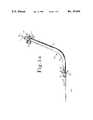
- FIGS. 1a-dare various illustrations of a stent according to the present invention.
- FIG. 1ais a side elevational view of a stent for facilitating the drainage of fluids within an obstructed duct.
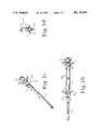
- FIG. 1bis a top plan view of the stent 10 of FIG. 1a.
- FIG. 1cis a perspective view of the out flow end of stent 10, while FIGS. 1-d is an end view of the outflow end of this stent.
- FIGS. 2a-bare illustrations of the stent of FIGS. 1a-d implanted within an obstructed duct to aid in the drainage of fluids therethrough.
- FIGS. 2a-bshow the stent implanted within the duct, with the outflow end of its drainage tube wholly within the duct, and its wick extending through the exit of the duct and into the receiving organ.
- the sphincter at the exit of the ductis open to allow the free flow of fluid out of the duct and into the receiving organ.
- the sphincteris closed to prevent the reflux of fluid and/or debris back into the duct.
- FIGS. 1a-dare various illustrations of a stent of the present invention, which will now be described with reference to these figures.
- Stent 10is made of radiopaque polyethylene and has an inflow, end portion 11 and an outflow end portion 12, and a drainage tube 13 therebetween.
- Inflow end portion 11defines inlet I for allowing fluid to enter into drainage tube 13, while outflow, end portion 12 defines outlet O for allowing fluid to exit drainage tube 13.
- At inflow end 11are two alternating rows of four radially extending flaps 11a which serve to aid in the anchoring of stent 10 within an obstructed duct.
- radially extending flaps 12aare located at outflow end portion 12 of stent 10, except that only one row of four flaps 12a, as shown, are incorporated at outflow end portion 12 for the prevention upward migration.
- the number, size, and orientation of flaps 11a and 12amay be modified to accommodate the mitration-preventing requirements of the particular stent to be implanted.
- Flaps 11a and 12aare simply constructed by slicing small longitudinal sections in stent 10 and orienting the sliced sections radially. It is preferred that the above described slices are made shallowly such that holes are not made within the drainage tube by the construction of flaps 11a and 12a.
- Drainage tube 13is comprised of a continuously uninterupted tube and provides a drainage passageway though an obstructed duct when stent 10 has been implanted therein. Drainage tube 13 has a 120° bend 13a at approximately one third of its overall length from outlet O. Bend 13a is incorporated in stent 10 to accommodate the anatomical structure of the duct into which stent 10 is to be implanted, which by this example is the biliary duct.
- Wick 12blocated at outflow end 12 of stent 10, is comprised of an extended arcical section of drainage tube 13 and serves to enhance drainage by providing a "wicking" effect for fluid as it exits outlet O. Wick 12b further serves to allow stent 10 to be implanted with its outflow end 12 positioned within duct 20 rather than extending into the receiving organ 30, thereby allowing sphincter 21 at the exit of duct 20 to function normally to prevent reflux. Additionally, wick 12b serves to facilitate removal by providing an exposed portion, extending through sphincter 21 and into receiving organ 30, which is easily graspable by an instrument inserted into the body to retain and remove stent 10.
- wick 12bhas an arcical cross-section of about 70° which is intended for illustrative purposes.
- Arcical cross-sections of wider or narrower dimension than specifically disclosed hereinmay serve to provide the intended and described novel functions of wick 12b and, as such, are considered to fall within the scope of this invention.
- FIGS. 2a-billustrate the stent of FIGS. 1a-d implanted within an obstructed duct 20 to aid in the drainage of fluids therethrough.
- flaps 11a and 12aserve to anchor stent 10 in place within duct 20 and prevent undesirable migration.
- Drainage tube 13maintains patency within duct 20, thereby allowing fluids to flow therethrough.
- Wick 12bprovides a wicking effect which enhances the further flow of fluid upon exiting drainage tube 13 at outlet O, while also allowing sphincter 21 to function normally, thereby serving to reduce the possible occurrence of reflux.
- sphincter 21The normal operation of sphincter 21 is illustrated by the comparison of FIGS. 2a and b.
- sphincter 21is opened to allow the free flow of fluid away from duct 20.
- wick 12benhances drainage by providing a wicking effect for fluid as it exits the outflow end of drainage tube 13.
- sphincter 21is closed to prevent reflux from occurring.
- sphincter 21closes about wick 12b to effectuate closure.
- wick 12balso serves the function of facilitating such removal by providing an exposed portion which is easily graspable by forceps or other instrument inserted for removal.
Landscapes
- Health & Medical Sciences (AREA)
- Engineering & Computer Science (AREA)
- Biomedical Technology (AREA)
- Life Sciences & Earth Sciences (AREA)
- Veterinary Medicine (AREA)
- Public Health (AREA)
- General Health & Medical Sciences (AREA)
- Heart & Thoracic Surgery (AREA)
- Animal Behavior & Ethology (AREA)
- Anesthesiology (AREA)
- Hematology (AREA)
- Otolaryngology (AREA)
- Ophthalmology & Optometry (AREA)
- Urology & Nephrology (AREA)
- Cardiology (AREA)
- Oral & Maxillofacial Surgery (AREA)
- Transplantation (AREA)
- Vascular Medicine (AREA)
- Media Introduction/Drainage Providing Device (AREA)
- Prostheses (AREA)
Abstract
Description
1. Field of the Invention
The field of the invention is indwelling stents which aid in the drainage of fluids within the body.
2. Description of the Prior Art
A number of various stents have been devised which are designed to aid in the drainage of fluids within the body. It is generally desirable that a stent being implanted for this purpose be easily implantable, that it maintain patency of the duct and its position within the duct after implantation, that reflux or backflow through the duct be avoided, and that the stent be easily removable.
Stents have been designed in a wide variety of shapes and sizes to effectuate these general requirements. One such example is shown by U.S. Pat. No. 5,052,998 to Zimmon which discloses an indwelling stent having flaps at its inflow end and a pigtail configuration at its outflow end to facilitate anchoring of the stent within the duct to be drained, and also has a series of drainage holes along its length to facilitate drainage. Other stents mentioned in the Zimmon patent, have commonly employed double flaps, or wings, or have incorporated pigtails on both ends, to hold the stent in place. Prior art stents have been provided both with and without the drainage holes shown in the Zimmon patent.
Reflux is the condition where fluids and/or debris are drawn backwardly up into the duct to be drained. This is undesirable in that it is counterproductive to the purpose of the stent being implanted to drain the duct. Reflux of debris into the stent can also potentially occlude the implanted stent within the duct, which can potentially cause severe aggravation to the condition being treated. Reflux is normally prevented by the functioning of a sphincter located where the duct exits into its receiving organ, however this sphincter operation is inhibited by the placement of an indwelling stent which acts to maintain the patency of the sphincter as well as the duct being drained.
To prevent reflux, U.S. Pat. No. 5,019,102 to Hoene discloses a stent with a dynamic hood-valve at the vesical end of the stent, located within the receiving organ at the downflow end of the obstructed duct. The hood-valve is comprised of a hood-shaped plastic foil that is attached to and partially surrounds the vesical end opening. A reflux pressure causes the hood-valve to fold over to close the vesical opening, thereby preventing retrograde flow from occurring.
Some stents have been devised which terminate within the duct to be drained to allow for normal sphincter operation. U.S. Pat. No. 4,955,859 to Zilber is one such example which suggests the use of a ureteral stent which terminates within the urethra to allow for the normal operation of the external sphincter in order to prevent incontinence.
It is known in the prior art to incorporate means for facilitating the removal of an indwelling stent from the body. U.S. Pat. No. 4,671,795 to Mulchin discloses one such example of an indwelling stent which has a suture attached to its end which extends out of the body and is tied to a button outside the body. The button prevents upward migration and may be pulled to remove the stent from the body. U.S. Pat. No. 4,913,683 to Gregory is another reference disclosing a stent system which utilizes sutures that extend outwardly of the patient and are pulled to remove the stent from the body. Zilber suggests the use of trailing sutures as an aid in the positioning of a stent being implanted. Zimmon suggests drawing the end of a large diameter stent (10 French or greater) to a reduced diameter to facilitate removal col. 3, lines 52-57! in an effort to compensate for the fact that larger diameter stents are more difficult to grasp and remove.
The present invention generally provides a new and unique indwelling stent which facilitates the drainage of fluids through a duct within the body. When implanted within an obstructed duct to be drained, a stent according to the present invention acts to enhance drainage while preventing reflux by allowing the sphincter at the exit of the duct to function normally. The stent is also easily removed when needed. According to the preferred embodiment disclosed herein, a double wing stent, having multiple flaps at each end and a continuous uninterrupted drainage tube therebetween, is implantable within an obstructed duct. Located at the outflow end of the drainage tube of the stent is a "wick" which is made of an extended arcical section of the drainage tube.
The stent, when implanted with the outflow end of its drainage tube within the duct, prevents reflux by allowing the sphincter at the exit of the duct to function normally. In this operative position, the wick extends through the remaining section of the duct and into the receiving organ. The wick serves to enhance drainage by providing a "wicking" effect for fluid as it exits the stent's outflow end and, with the outflow end of the drainage tube wholly within the duct, the sphincter at the exit of the duct is allowed to function normally, thereby preventing reflux. In this way, the implanted stent tends to remain unobstructed for longer periods of time and therefore is safer for the patient and may remain in place without the need for replacement for longer periods. The wick further serves to facilitate removal by providing an exposed portion which is easily graspable by an instrument inserted into the body to retain and remove the stent.
It is an object of the present invention to provide an improved stent for the drainage of fluids within the body.
It a further object of the present invention to provide such a stent which facilitates drainage within an obstructed duct while allowing the sphincter at the exit of the duct to function normally to inhibit reflux.
It a further object of the present invention to provide such a stent which is easy to remove when needed.
It is yet another object to provide such a stent which has the advantage of simplicity of construction.
These and other objects and advantages will be apparent from a review of the following specification and claims.
FIGS. 1a-d are various illustrations of a stent according to the present invention. FIG. 1a is a side elevational view of a stent for facilitating the drainage of fluids within an obstructed duct. FIG. 1b is a top plan view of thestent 10 of FIG. 1a. FIG. 1c is a perspective view of the out flow end ofstent 10, while FIGS. 1-d is an end view of the outflow end of this stent.
FIGS. 2a-b are illustrations of the stent of FIGS. 1a-d implanted within an obstructed duct to aid in the drainage of fluids therethrough. FIGS. 2a-b show the stent implanted within the duct, with the outflow end of its drainage tube wholly within the duct, and its wick extending through the exit of the duct and into the receiving organ. In FIG. 2a, the sphincter at the exit of the duct is open to allow the free flow of fluid out of the duct and into the receiving organ. In FIG. 2b, the sphincter is closed to prevent the reflux of fluid and/or debris back into the duct.
For the purposes of promoting an understanding of the principles of the invention, reference will now be made to the embodiment illustrated in the drawings and specific language will be used to describe the same. It will nevertheless be understood that no limitation of the scope of the invention is thereby intended, such alterations and further modifications in the illustrated device, and such further applications of the principles of the invention as illustrated therein being contemplated as would normally occur to one skilled in the art to which the invention relates.
FIGS. 1a-d are various illustrations of a stent of the present invention, which will now be described with reference to these figures.Stent 10 is made of radiopaque polyethylene and has an inflow, end portion 11 and anoutflow end portion 12, and adrainage tube 13 therebetween. Inflow end portion 11 defines inlet I for allowing fluid to enter intodrainage tube 13, while outflow,end portion 12 defines outlet O for allowing fluid to exitdrainage tube 13. At inflow end 11 are two alternating rows of four radially extending flaps 11a which serve to aid in the anchoring ofstent 10 within an obstructed duct. In the same manner and for the same purpose, radially extending flaps 12a are located atoutflow end portion 12 ofstent 10, except that only one row of four flaps 12a, as shown, are incorporated atoutflow end portion 12 for the prevention upward migration. The number, size, and orientation of flaps 11a and 12a may be modified to accommodate the mitration-preventing requirements of the particular stent to be implanted.
Flaps 11a and 12a are simply constructed by slicing small longitudinal sections instent 10 and orienting the sliced sections radially. It is preferred that the above described slices are made shallowly such that holes are not made within the drainage tube by the construction of flaps 11a and 12a.
In the embodiment shown,wick 12b has an arcical cross-section of about 70° which is intended for illustrative purposes. Arcical cross-sections of wider or narrower dimension than specifically disclosed herein may serve to provide the intended and described novel functions ofwick 12b and, as such, are considered to fall within the scope of this invention.
FIGS. 2a-b illustrate the stent of FIGS. 1a-d implanted within an obstructedduct 20 to aid in the drainage of fluids therethrough. When implanted, flaps 11a and 12a serve to anchorstent 10 in place withinduct 20 and prevent undesirable migration.Drainage tube 13 maintains patency withinduct 20, thereby allowing fluids to flow therethrough.Wick 12b provides a wicking effect which enhances the further flow of fluid upon exitingdrainage tube 13 at outlet O, while also allowingsphincter 21 to function normally, thereby serving to reduce the possible occurrence of reflux.
The normal operation ofsphincter 21 is illustrated by the comparison of FIGS. 2a and b. In FIG. 2a,sphincter 21 is opened to allow the free flow of fluid away fromduct 20. In this state,wick 12b enhances drainage by providing a wicking effect for fluid as it exits the outflow end ofdrainage tube 13. In FIG. 2b,sphincter 21 is closed to prevent reflux from occurring. In this state,sphincter 21 closes aboutwick 12b to effectuate closure. Whenstent 10 is to be removed,wick 12b also serves the function of facilitating such removal by providing an exposed portion which is easily graspable by forceps or other instrument inserted for removal.
While the invention has been illustrated and described in detail in the drawings and foregoing description, the same is to be considered as illustrative and not restrictive in character, it being understood that only the preferred embodiment has been shown and described and that all changes and modifications that come within the spirit of the invention are desired to be protected.
Claims (12)
1. A stent for facilitating the drainage of fluids through an obstructed duct within the body and through a sphincter at the exit of the obstructed duct while inhibiting reflux by allowing for the normal functioning of the sphincter, said stent comprising:
an inflow end portion, an outflow end portion, and a drainage tube therebetween, said inflow end portion defining inlet means for allowing fluid to enter into the inflow end of said drainage tube, said outflow end portion defining outlet means for allowing fluid to exit the outflow end of said drainage tube;
means for anchoring said stent in an obstructed duct with the inflow end of said drainage tube positioned within the duct; and
means for enhancing the drainage for fluid exiting said outlet means from within the duct while inhibiting reflux by allowing for the sphincter at the exit of the duct to function in a normal manner, said drainage enhancing/reflux inhibiting means including a wick extending from the outflow end of said drainage tube and comprising an extended arcical section of said drainage tube, whereby said wick enhances drainage by providing a wicking effect for fluid exiting said drainage tube while reducing the possible effect of reflux by allowing the sphincter at the exit of the duct to function in a normal manner.
2. The stent of claim 1 in which, when said stent has been implanted in a duct to be drained, said wick extends through the sphincter at the exit of the duct with said sphincter being allowed to function normally by closing about said wick, and further whereby said wick provides means for facilitating removal of said stent by providing an exposed portion of said stent which is easily graspable by an instrument inserted into the body for retention and removal.
3. The stent of claim 1 wherein the arcical cross-section of said wick is about 70°.
4. The stent of claim 1 in which said anchoring means includes radially extending flaps at each of said inflow end portion and said outflow end portion.
5. The stent of claim 2 in which said anchoring means includes radially extending flaps at each of said inflow end portion and said outflow end portion.
6. The stent of claim 2 in which said anchoring means includes multiple radially extending flaps at each of said inflow end portion and said outflow end portion.
7. The stent of claim 2 in which there are two rows of four equicircumferentially spaced radially extending flaps at said inflow end portion and one row of four equicircumferentially spaced radially extending flaps at said outflow end portion.
8. The stent of claim 1 wherein said drainage tube defines a continuously uninterrupted drainage lumen between said inflow end portion and said outflow end portion.
9. The stent of claim 2 wherein said drainage tube is defines a continuously uninterrupted drainage lumen between said inflow end portion and said outflow end portion. .Iadd.
10. A stent for facilitating the drainage of fluids through an obstructed duct within the body, said stent comprising:
an inflow end portion, an outflow end portion, and a drainage tube therebetween, said inflow end portion defining inlet means for allowing fluid to enter into the inflow end of said drainage tube, said outflow end portion defining outlet means for allowing fluid to exit the outflow end of said drainage tube; and
means for anchoring said stent in an obstructed duct with the inflow end of said drainage tube positioned within the duct;
wherein said anchoring means comprise a plurality of radially extending flaps formed by slicing small longitudinal sections in said drainage tube and orienting said sliced sections radially, and wherein said sliced sections are made shallowly such that holes are not made in said drainage tube. .Iaddend..Iadd.11. The stent of claim 10 wherein there are two rows of a first plurality of radially extending flaps at said inflow end portion and one row of a second plurality radially extending flaps at said outflow end portion. .Iaddend..Iadd.12. The stent of claim 10 wherein there are two rows of four equicircumferentially spaced radially extending flaps at said inflow end portion and one row of four equicircumferentially spaced radially extending flaps at said outflow end portion. .Iaddend..Iadd.13. A stent for facilitating the drainage of fluids through an obstructed duct within the body, said stent comprising:
an inflow end portion, an outflow end portion, and a drainage tube therebetween, said inflow end portion defining inlet means for allowing fluid to enter into the inflow end of said drainage tube, said outflow end portion defining outlet means for allowing fluid to exit the outflow end of said drainage tube; and
means for anchoring said stent in an obstructed duct with the inflow end of said drainage tube positioned within the duct;
wherein said anchoring means comprise a plurality of radially extending flaps formed by slicing small longitudinal sections in said drainage tube and orienting said sliced sections radially, and wherein said drainage tube defines a continuously uninterrupted drainage lumen between said
inflow end portion and said outflow end portion. .Iaddend..Iadd.14. A stent for facilitating the drainage of fluids through an obstructed duct within the body, said stent comprising:
an inflow end portion, an outflow end portion, and a drainage tube therebetween, said inflow end portion defining inlet means for allowing fluid to enter into the inflow end of said drainage tube, said outflow end portion defining outlet means for allowing fluid to exit the outflow end of said drainage tube; and
means for anchoring said stent in an obstructed duct with the inflow end of said drainage tube positioned within the duct;
wherein said anchoring means comprise two rows of a first plurality of radially extending flaps at said inflow end portion and one row of a second plurality of radially extending flaps at said outflow end portion, and wherein said flaps are formed by slicing small longitudinal sections in said drainage tube such that one end of each flap is severed from drainage tube. .Iaddend..Iadd.15. The stent of claim 14 wherein said flaps are formed by orienting said sliced sections radially. .Iaddend..Iadd.16. A stent for facilitating the drainage of fluids through an obstructed duct within the body, said stent comprising:
an inflow end portion, an outflow end portion, and a drainage tube therebetween, said inflow end portion defining inlet means for allowing fluid to enter into the inflow end of said drainage tube, said outflow end portion defining outlet means for allowing fluid to exit the outflow end of said drainage tube; and
means for anchoring said stent in an obstructed duct with the inflow end of said drainage tube positioned within the duct;
wherein said anchoring means comprise two rows of a first plurality of radially extending flaps at said inflow end portion and one row of a second plurality of radially extending flaps at said outflow end portion;
wherein said flaps are formed by a small longitudinal sections in said drainage tube and orienting said sliced sections radially, and wherein said sliced sections are made shallowly such that holes are not made in
said drainage tube. .Iaddend..Iadd.17. The stent of claim 14 wherein said first plurality of flaps comprise two rows of four equicircumferentially spaced flaps and said second plurality of flaps comprise one row of four equicircumferentially spaced flaps. .Iaddend..Iadd.18. A stent for facilitating the drainage of fluids through an obstructed duct within the body, said stent comprising:
an inflow end portion, an outflow end portion, and a drainage tube therebetween, said inflow end portion defining inlet means for allowing fluid to enter into the inflow end of said drainage tube, said outflow end portion defining outlet means for allowing fluid to exit the outflow end of said drainage tube; and
means for anchoring said stent in an obstructed duct with the inflow end of said drainage tube positioned within the duct;
wherein said anchoring means comprise two rows of a first plurality of radially extending flaps at said inflow end portion and one row of a second plurality of radially extending flaps at said outflow end portion; and
wherein said drainage tube defines a continuously uninterrupted drainage lumen between said inflow end portion and said outflow end portion. .Iaddend.
Priority Applications (1)
| Application Number | Priority Date | Filing Date | Title |
|---|---|---|---|
| US08/367,801USRE35849E (en) | 1992-01-15 | 1994-12-30 | Indwelling stent |
Applications Claiming Priority (2)
| Application Number | Priority Date | Filing Date | Title |
|---|---|---|---|
| US07/821,001US5176626A (en) | 1992-01-15 | 1992-01-15 | Indwelling stent |
| US08/367,801USRE35849E (en) | 1992-01-15 | 1994-12-30 | Indwelling stent |
Related Parent Applications (1)
| Application Number | Title | Priority Date | Filing Date |
|---|---|---|---|
| US07/821,001ReissueUS5176626A (en) | 1992-01-15 | 1992-01-15 | Indwelling stent |
Publications (1)
| Publication Number | Publication Date |
|---|---|
| USRE35849Etrue USRE35849E (en) | 1998-07-14 |
Family
ID=25232246
Family Applications (2)
| Application Number | Title | Priority Date | Filing Date |
|---|---|---|---|
| US07/821,001CeasedUS5176626A (en) | 1992-01-15 | 1992-01-15 | Indwelling stent |
| US08/367,801Expired - LifetimeUSRE35849E (en) | 1992-01-15 | 1994-12-30 | Indwelling stent |
Family Applications Before (1)
| Application Number | Title | Priority Date | Filing Date |
|---|---|---|---|
| US07/821,001CeasedUS5176626A (en) | 1992-01-15 | 1992-01-15 | Indwelling stent |
Country Status (1)
| Country | Link |
|---|---|
| US (2) | US5176626A (en) |
Cited By (34)
| Publication number | Priority date | Publication date | Assignee | Title |
|---|---|---|---|---|
| US6162237A (en) | 1999-04-19 | 2000-12-19 | Chan; Winston Kam Yew | Temporary intravascular stent for use in retrohepatic IVC or hepatic vein injury |
| US20020107540A1 (en)* | 2001-01-23 | 2002-08-08 | Whalen Mark J. | Endourethral device & method |
| US20030018307A1 (en)* | 1997-12-12 | 2003-01-23 | Boris Reydel | Body canal intrusion instrumentation having bidirectional coefficient of surface friction with body tissue |
| US20030060894A1 (en)* | 1998-08-31 | 2003-03-27 | Dua Kulwinders S. | Prosthesis having a sleeve valve |
| US20030078467A1 (en)* | 2001-10-18 | 2003-04-24 | Whalen Mark J. | Endourethral device & method |
| US20030208183A1 (en)* | 2000-08-07 | 2003-11-06 | Whalen Mark J. | Endourethral device & method |
| US6666883B1 (en) | 1996-06-06 | 2003-12-23 | Jacques Seguin | Endoprosthesis for vascular bifurcation |
| US20040015155A1 (en)* | 1999-12-01 | 2004-01-22 | Abbeymoor Medical, Inc. | Magnetic retrieval device and method of use |
| US20040024362A1 (en)* | 2002-04-11 | 2004-02-05 | Hugh Trout | Stabilizing surgical delivery apparatus and method of use |
| US20040193092A1 (en)* | 2003-03-26 | 2004-09-30 | Scimed Life Systems, Inc. | Self-retaining stent |
| US20040199262A1 (en)* | 1998-08-31 | 2004-10-07 | Wilson-Cook Medical Incorporated | Prosthesis having a sleeve valve |
| US20040254602A1 (en)* | 2003-03-28 | 2004-12-16 | Lehe Cathleen Von | Double ended intravascular medical device |
| US20050107721A1 (en)* | 2000-08-31 | 2005-05-19 | Abbeymoor Medical, Inc. | Diagnostic urethral assembly & method |
| US7001327B2 (en) | 2000-02-01 | 2006-02-21 | Abbeymoor Medical, Inc. | Urinary flow control device and method |
| US7041139B2 (en) | 2001-12-11 | 2006-05-09 | Boston Scientific Scimed, Inc. | Ureteral stents and related methods |
| US7048698B2 (en) | 2001-06-22 | 2006-05-23 | Abbeymoor Medical, Inc. | Urethral profiling device and methodology |
| WO2006124108A1 (en)* | 2005-05-11 | 2006-11-23 | Boston Scientific Scimed, Inc. | Ureteral stent with conforming retention structure |
| US20070016306A1 (en)* | 1998-08-31 | 2007-01-18 | Wilson-Cook Medical Inc. | Prosthesis having a sleeve valve |
| US7211114B2 (en) | 2002-08-26 | 2007-05-01 | The Trustees Of Columbia University In The City Of New York | Endoscopic gastric bypass |
| US20080051911A1 (en)* | 2006-08-23 | 2008-02-28 | Wilson-Cook Medical Inc. | Stent with antimicrobial drainage lumen surface |
| US20080086214A1 (en)* | 1998-08-31 | 2008-04-10 | Wilson-Cook Medical Inc. | Medical device having a sleeve valve with bioactive agent |
| US20080208314A1 (en)* | 2007-02-22 | 2008-08-28 | Wilson-Cook Medical Inc. | Prosthesis having a sleeve valve |
| US20080228126A1 (en)* | 2006-03-23 | 2008-09-18 | The Trustees Of Columbia University In The City Of New York | Method of inhibiting disruption of the healing process in a physically modified stomach |
| US20090048654A1 (en)* | 2007-08-15 | 2009-02-19 | Wilson-Cook Medical Inc. | Deployment System for Soft Stents |
| US20090093822A1 (en)* | 2007-10-03 | 2009-04-09 | Wilson-Cook Medical Inc. | Magnetic stent removal |
| US20110087252A1 (en)* | 2009-10-08 | 2011-04-14 | Wilson-Cook Medical Inc. | Biliary decompression and anastomosis stent |
| WO2011023929A3 (en)* | 2009-08-24 | 2011-08-18 | Alternative Urological Catheter Systems Limited | Suprapubic urethral catheters |
| US20110224775A1 (en)* | 2010-03-11 | 2011-09-15 | Wilson-Cook Medical Inc. | Stent Geometry |
| US20130066328A1 (en)* | 2011-04-07 | 2013-03-14 | Jai Singh | General uterine manipulator and system |
| US20130197536A1 (en)* | 2011-04-07 | 2013-08-01 | Jai Singh | General uterine manipulator and system |
| US8574221B2 (en) | 2011-09-09 | 2013-11-05 | Cook Medical Technologies Llc | Tubular medical device |
| US8740876B2 (en) | 2010-05-10 | 2014-06-03 | Cook Medical Technologies Llc | Device for external percutaneous connections |
| US20160081717A1 (en)* | 2011-04-07 | 2016-03-24 | Jai Singh | General uterine manipulator and system |
| US9532837B2 (en) | 2012-04-20 | 2017-01-03 | Jiwan Steven Singh | Repositionable medical instrument support systems, devices, and methods |
Families Citing this family (131)
| Publication number | Priority date | Publication date | Assignee | Title |
|---|---|---|---|---|
| US5782903A (en)* | 1987-10-19 | 1998-07-21 | Medtronic, Inc. | Intravascular stent and method |
| US5549559A (en) | 1990-03-22 | 1996-08-27 | Argomed Ltd. | Thermal treatment apparatus |
| FR2701648B1 (en)* | 1993-02-19 | 1995-03-31 | Marian Devonec | Prosthesis intended for the treatment of a light or natural way, in particular endo-urethral prosthesis. |
| US6576008B2 (en) | 1993-02-19 | 2003-06-10 | Scimed Life Systems, Inc. | Methods and device for inserting and withdrawing a two piece stent across a constricting anatomic structure |
| ATE420628T1 (en)* | 1993-07-19 | 2009-01-15 | Angiotech Pharm Inc | ANTI-ANGIogenic AGENTS AND METHODS OF USE THEREOF |
| US5486191A (en)* | 1994-02-02 | 1996-01-23 | John Hopkins University | Winged biliary stent |
| US6849063B1 (en) | 1994-03-11 | 2005-02-01 | Wit Ip Corporation | Thermal treatment apparatus |
| US6774278B1 (en)* | 1995-06-07 | 2004-08-10 | Cook Incorporated | Coated implantable medical device |
| US6991614B2 (en)* | 1995-11-07 | 2006-01-31 | Boston Scientific Scimed, Inc. | Ureteral stent for improved patient comfort |
| US6676623B2 (en) | 2001-05-04 | 2004-01-13 | Scimed Life Systems, Inc. | Drainage devices and methods |
| US6849069B1 (en)* | 1995-11-07 | 2005-02-01 | Boston Scientitfic Corporation | Medical device with tail(s) for assisting flow of urine |
| JPH1057496A (en)* | 1996-06-14 | 1998-03-03 | Olympus Optical Co Ltd | Indwelling tube for medical use |
| US6059757A (en)* | 1996-06-18 | 2000-05-09 | Cardeon | Single lumen catheter with controlled antegrade and retrograde flow |
| US5795319A (en)* | 1997-03-07 | 1998-08-18 | Circon Corporation | Easily removable ureteral stent |
| US6251418B1 (en)* | 1997-12-18 | 2001-06-26 | C.R. Bard, Inc. | Systems and methods for local delivery of an agent |
| US6197324B1 (en) | 1997-12-18 | 2001-03-06 | C. R. Bard, Inc. | System and methods for local delivery of an agent |
| WO2000015275A2 (en)* | 1998-09-10 | 2000-03-23 | Percardia, Inc. | Body fluid shunt device and method of use |
| US6893430B2 (en) | 1998-02-04 | 2005-05-17 | Wit Ip Corporation | Urethral catheter and guide |
| US6196230B1 (en)* | 1998-09-10 | 2001-03-06 | Percardia, Inc. | Stent delivery system and method of use |
| US6689121B1 (en) | 1998-09-24 | 2004-02-10 | C. R. Bard, Inc. | Systems and methods for treating ischemia |
| US6432126B1 (en)* | 1998-09-30 | 2002-08-13 | C.R. Bard, Inc. | Flexible vascular inducing implants |
| US6248112B1 (en) | 1998-09-30 | 2001-06-19 | C. R. Bard, Inc. | Implant delivery system |
| US6458092B1 (en) | 1998-09-30 | 2002-10-01 | C. R. Bard, Inc. | Vascular inducing implants |
| US8480610B1 (en)* | 1998-12-08 | 2013-07-09 | Frank C. Hill | Ear tube and method of insertion |
| US6692520B1 (en) | 1998-12-15 | 2004-02-17 | C. R. Bard, Inc. | Systems and methods for imbedded intramuscular implants |
| US6332892B1 (en) | 1999-03-02 | 2001-12-25 | Scimed Life Systems, Inc. | Medical device with one or more helical coils |
| US6986784B1 (en) | 1999-05-14 | 2006-01-17 | C. R. Bard, Inc. | Implant anchor systems |
| US6855160B1 (en) | 1999-08-04 | 2005-02-15 | C. R. Bard, Inc. | Implant and agent delivery device |
| JP4108882B2 (en) | 1999-08-04 | 2008-06-25 | オリンパス株式会社 | Endoscope wall fixture |
| US6547761B2 (en) | 2000-01-07 | 2003-04-15 | Scimed Life Systems, Inc. | Drainage catheter |
| US7232421B1 (en) | 2000-05-12 | 2007-06-19 | C. R. Bard, Inc. | Agent delivery systems |
| US6764519B2 (en)* | 2000-05-26 | 2004-07-20 | Scimed Life Systems, Inc. | Ureteral stent |
| US6716252B2 (en) | 2000-06-30 | 2004-04-06 | Wit Ip Corporation | Prostatic stent with localized tissue engaging anchoring means and methods for inhibiting obstruction of the prostatic urethra |
| US7204847B1 (en) | 2000-07-28 | 2007-04-17 | C. R. Bard, Inc. | Implant anchor systems |
| DE10115740A1 (en) | 2001-03-26 | 2002-10-02 | Ulrich Speck | Preparation for restenosis prophylaxis |
| US6719804B2 (en) | 2001-04-02 | 2004-04-13 | Scimed Life Systems, Inc. | Medical stent and related methods |
| US6494855B2 (en)* | 2001-05-16 | 2002-12-17 | Scimed Life Systems, Inc. | Draining bodily fluid |
| US6981964B2 (en) | 2001-05-22 | 2006-01-03 | Boston Scientific Scimed, Inc. | Draining bodily fluids with a stent |
| US6790223B2 (en) | 2001-09-21 | 2004-09-14 | Scimed Life Systems, Inc. | Delivering a uretheral stent |
| JP4043210B2 (en)* | 2001-10-09 | 2008-02-06 | オリンパス株式会社 | Stent |
| US6620202B2 (en)* | 2001-10-16 | 2003-09-16 | Scimed Life Systems, Inc. | Medical stent with variable coil and related methods |
| JP4043216B2 (en)* | 2001-10-30 | 2008-02-06 | オリンパス株式会社 | Stent |
| DE10159708A1 (en)* | 2001-12-05 | 2003-06-18 | Bayer Ag | Alkaline chloride electrolysis cell with gas diffusion electrodes |
| US20040068314A1 (en)* | 2002-01-16 | 2004-04-08 | Jones Donald K. | Detachable self -expanding aneurysm cover device |
| US6913625B2 (en) | 2002-03-07 | 2005-07-05 | Scimed Life Systems, Inc. | Ureteral stent |
| CA2478065C (en) | 2002-03-08 | 2013-01-08 | Eisai Co. Ltd. | Macrocyclic compounds useful as pharmaceuticals |
| US8328877B2 (en)* | 2002-03-19 | 2012-12-11 | Boston Scientific Scimed, Inc. | Stent retention element and related methods |
| IL163868A0 (en) | 2002-03-22 | 2005-12-18 | Eisai Co Ltd | Hermiasterlin derivatives and uses thereof |
| US6949125B2 (en)* | 2002-04-16 | 2005-09-27 | Boston Scientific Scimed, Inc. | Ureteral stent with end-effector and related methods |
| US7485150B2 (en)* | 2002-04-23 | 2009-02-03 | Boston Scientific Scimed, Inc. | Drainage devices and methods |
| DE10244847A1 (en)* | 2002-09-20 | 2004-04-01 | Ulrich Prof. Dr. Speck | Medical device for drug delivery |
| US6733536B1 (en)* | 2002-10-22 | 2004-05-11 | Scimed Life Systems | Male urethral stent device |
| US7182745B2 (en)* | 2003-03-25 | 2007-02-27 | Boston Scientific Scimed, Inc. | Retaining stent |
| US6929663B2 (en)* | 2003-03-26 | 2005-08-16 | Boston Scientific Scimed, Inc. | Longitudinally expanding medical device |
| US7651529B2 (en)* | 2003-05-09 | 2010-01-26 | Boston Scientific Scimed, Inc. | Stricture retractor |
| US8876882B2 (en)* | 2003-10-10 | 2014-11-04 | Mark Gelido Barongan | Cutting stent |
| US7338530B2 (en)* | 2003-11-24 | 2008-03-04 | Checkmed Systems, Inc. | Stent |
| US20050240141A1 (en)* | 2004-04-26 | 2005-10-27 | Peter Aliski | Stent kidney curl improvements |
| US7470247B2 (en)* | 2004-04-26 | 2008-12-30 | Gyrus Acmi, Inc. | Ureteral stent |
| US7507218B2 (en)* | 2004-04-26 | 2009-03-24 | Gyrus Acmi, Inc. | Stent with flexible elements |
| EP1773871B1 (en) | 2004-06-17 | 2014-10-15 | Thrasos Innovation, Inc. | Tdf-related compounds and analogs thereof |
| US8730031B2 (en) | 2005-04-28 | 2014-05-20 | Proteus Digital Health, Inc. | Communication system using an implantable device |
| US8912908B2 (en) | 2005-04-28 | 2014-12-16 | Proteus Digital Health, Inc. | Communication system with remote activation |
| US9198608B2 (en) | 2005-04-28 | 2015-12-01 | Proteus Digital Health, Inc. | Communication system incorporated in a container |
| US8836513B2 (en) | 2006-04-28 | 2014-09-16 | Proteus Digital Health, Inc. | Communication system incorporated in an ingestible product |
| EP3827747A1 (en)* | 2005-04-28 | 2021-06-02 | Otsuka Pharmaceutical Co., Ltd. | Pharma-informatics system |
| US8802183B2 (en) | 2005-04-28 | 2014-08-12 | Proteus Digital Health, Inc. | Communication system with enhanced partial power source and method of manufacturing same |
| US8547248B2 (en)* | 2005-09-01 | 2013-10-01 | Proteus Digital Health, Inc. | Implantable zero-wire communications system |
| EP2927241A1 (en) | 2005-09-20 | 2015-10-07 | Thrasos Innovation, Inc. | TDF-related compounds and analogs thereof |
| JP2009544338A (en) | 2006-05-02 | 2009-12-17 | プロテウス バイオメディカル インコーポレイテッド | Treatment regimen customized to the patient |
| US20080294255A1 (en)* | 2006-05-23 | 2008-11-27 | Donald Albert Gonzales | Sinus Tube |
| WO2008006097A2 (en)* | 2006-07-07 | 2008-01-10 | Intezyne Technologies Llc | Covalent modification of metal surfaces |
| EP2087589B1 (en)* | 2006-10-17 | 2011-11-23 | Proteus Biomedical, Inc. | Low voltage oscillator for medical devices |
| SG175681A1 (en) | 2006-10-25 | 2011-11-28 | Proteus Biomedical Inc | Controlled activation ingestible identifier |
| US8718193B2 (en)* | 2006-11-20 | 2014-05-06 | Proteus Digital Health, Inc. | Active signal processing personal health signal receivers |
| CN101686800A (en) | 2007-02-01 | 2010-03-31 | 普罗秋斯生物医学公司 | Ingestible Event Marker System |
| US8956288B2 (en) | 2007-02-14 | 2015-02-17 | Proteus Digital Health, Inc. | In-body power source having high surface area electrode |
| EP2063771A1 (en) | 2007-03-09 | 2009-06-03 | Proteus Biomedical, Inc. | In-body device having a deployable antenna |
| EP2124725A1 (en)* | 2007-03-09 | 2009-12-02 | Proteus Biomedical, Inc. | In-body device having a multi-directional transmitter |
| US8115618B2 (en) | 2007-05-24 | 2012-02-14 | Proteus Biomedical, Inc. | RFID antenna for in-body device |
| DK2192946T3 (en) | 2007-09-25 | 2022-11-21 | Otsuka Pharma Co Ltd | In-body device with virtual dipole signal amplification |
| KR101586193B1 (en) | 2007-11-27 | 2016-01-18 | 프로테우스 디지털 헬스, 인코포레이티드 | Transbody communication systems employing communication channels |
| CN104376659B (en)* | 2008-03-05 | 2019-10-25 | 普罗透斯数字保健公司 | The ingestible event flag of multi-modal communications and system, and the method using it |
| US10245165B2 (en)* | 2009-04-02 | 2019-04-02 | Q3 Medical Devices Limited | Stent |
| US11207199B2 (en)* | 2008-06-11 | 2021-12-28 | Q3 Medical Devices Limited | Stent with anti-migration devices |
| AU2009268827B2 (en) | 2008-07-08 | 2013-10-24 | Proteus Digital Health, Inc. | Ingestible event marker data framework |
| MY154217A (en) | 2008-08-13 | 2015-05-15 | Proteus Digital Health Inc | Ingestible circuitry |
| WO2010045385A2 (en)* | 2008-10-14 | 2010-04-22 | Proteus Biomedical, Inc. | Method and system for incorporating physiologic data in a gaming environment |
| EP2349080B1 (en)* | 2008-10-22 | 2016-04-13 | Boston Scientific Scimed, Inc. | Shape memory tubular stent with grooves |
| US8036748B2 (en)* | 2008-11-13 | 2011-10-11 | Proteus Biomedical, Inc. | Ingestible therapy activator system and method |
| EP2358270A4 (en)* | 2008-12-11 | 2014-08-13 | Proteus Digital Health Inc | Evaluation of gastrointestinal function using portable electroviscerography systems and methods of using the same |
| US8192500B2 (en)* | 2008-12-12 | 2012-06-05 | Boston Scientific Scimed, Inc. | Ureteral stent |
| TWI503101B (en) | 2008-12-15 | 2015-10-11 | Proteus Digital Health Inc | Body-associated receiver and method |
| US9659423B2 (en) | 2008-12-15 | 2017-05-23 | Proteus Digital Health, Inc. | Personal authentication apparatus system and method |
| US9439566B2 (en) | 2008-12-15 | 2016-09-13 | Proteus Digital Health, Inc. | Re-wearable wireless device |
| US8512272B2 (en) | 2008-12-22 | 2013-08-20 | Boston Scientific Scimed, Inc. | Ureteral stent |
| KR20110103446A (en) | 2009-01-06 | 2011-09-20 | 프로테우스 바이오메디컬, 인코포레이티드 | Intake-Related Biofeedback and Individualized Medical Treatment Methods and Systems |
| SG172847A1 (en) | 2009-01-06 | 2011-08-29 | Proteus Biomedical Inc | Pharmaceutical dosages delivery system |
| WO2010111403A2 (en) | 2009-03-25 | 2010-09-30 | Proteus Biomedical, Inc. | Probablistic pharmacokinetic and pharmacodynamic modeling |
| EP3906845A1 (en)* | 2009-04-28 | 2021-11-10 | Otsuka Pharmaceutical Co., Ltd. | Highly reliable ingestible event markers |
| EP2432458A4 (en) | 2009-05-12 | 2014-02-12 | Proteus Digital Health Inc | Ingestible event markers comprising an ingestible component |
| US20100312338A1 (en)* | 2009-06-05 | 2010-12-09 | Entrigue Surgical, Inc. | Systems, devices and methods for providing therapy to an anatomical structure |
| US8558563B2 (en) | 2009-08-21 | 2013-10-15 | Proteus Digital Health, Inc. | Apparatus and method for measuring biochemical parameters |
| US20110054448A1 (en)* | 2009-08-28 | 2011-03-03 | Navilyst Medical, Inc. | Medical device containing catheter anchoring feature |
| TWI517050B (en) | 2009-11-04 | 2016-01-11 | 普羅托斯數位健康公司 | System for supply chain management |
| UA109424C2 (en) | 2009-12-02 | 2015-08-25 | PHARMACEUTICAL PRODUCT, PHARMACEUTICAL TABLE WITH ELECTRONIC MARKER AND METHOD OF MANUFACTURING PHARMACEUTICAL TABLETS | |
| BR112012019212A2 (en) | 2010-02-01 | 2017-06-13 | Proteus Digital Health Inc | data collection system |
| WO2011127252A2 (en) | 2010-04-07 | 2011-10-13 | Proteus Biomedical, Inc. | Miniature ingestible device |
| TWI557672B (en) | 2010-05-19 | 2016-11-11 | 波提亞斯數位康健公司 | Computer system and computer-implemented method to track medication from manufacturer to a patient, apparatus and method for confirming delivery of medication to a patient, patient interface device |
| JP2014504902A (en) | 2010-11-22 | 2014-02-27 | プロテウス デジタル ヘルス, インコーポレイテッド | Ingestible device with medicinal product |
| WO2012125425A2 (en) | 2011-03-11 | 2012-09-20 | Proteus Biomedical, Inc. | Wearable personal body associated device with various physical configurations |
| WO2015112603A1 (en) | 2014-01-21 | 2015-07-30 | Proteus Digital Health, Inc. | Masticable ingestible product and communication system therefor |
| US9756874B2 (en) | 2011-07-11 | 2017-09-12 | Proteus Digital Health, Inc. | Masticable ingestible product and communication system therefor |
| PH12014500174A1 (en) | 2011-07-21 | 2024-02-12 | Proteus Digital Health Inc | Mobile communication device, system, and method |
| US9235683B2 (en) | 2011-11-09 | 2016-01-12 | Proteus Digital Health, Inc. | Apparatus, system, and method for managing adherence to a regimen |
| EP2874886B1 (en) | 2012-07-23 | 2023-12-20 | Otsuka Pharmaceutical Co., Ltd. | Techniques for manufacturing ingestible event markers comprising an ingestible component |
| AU2013331417B2 (en) | 2012-10-18 | 2016-06-02 | Proteus Digital Health, Inc. | Apparatus, system, and method to adaptively optimize power dissipation and broadcast power in a power source for a communication device |
| ES2472122B1 (en)* | 2012-12-27 | 2015-04-13 | Fundación Centro De Cirugía Mínima Invasión Jesús Usón | Self-retentive and anti-reflux ureteral catheter |
| US11149123B2 (en) | 2013-01-29 | 2021-10-19 | Otsuka Pharmaceutical Co., Ltd. | Highly-swellable polymeric films and compositions comprising the same |
| WO2014144738A1 (en) | 2013-03-15 | 2014-09-18 | Proteus Digital Health, Inc. | Metal detector apparatus, system, and method |
| JP6498177B2 (en) | 2013-03-15 | 2019-04-10 | プロテウス デジタル ヘルス, インコーポレイテッド | Identity authentication system and method |
| EP3005281A4 (en) | 2013-06-04 | 2017-06-28 | Proteus Digital Health, Inc. | System, apparatus and methods for data collection and assessing outcomes |
| US9796576B2 (en) | 2013-08-30 | 2017-10-24 | Proteus Digital Health, Inc. | Container with electronically controlled interlock |
| CA2965941C (en) | 2013-09-20 | 2020-01-28 | Proteus Digital Health, Inc. | Methods, devices and systems for receiving and decoding a signal in the presence of noise using slices and warping |
| WO2015044722A1 (en) | 2013-09-24 | 2015-04-02 | Proteus Digital Health, Inc. | Method and apparatus for use with received electromagnetic signal at a frequency not known exactly in advance |
| US10084880B2 (en) | 2013-11-04 | 2018-09-25 | Proteus Digital Health, Inc. | Social media networking based on physiologic information |
| JP6178012B2 (en)* | 2014-04-04 | 2017-08-09 | ジャイラス エーシーエムアイ インク | Ureteral stent with anti-migration features |
| US10226606B2 (en)* | 2014-04-10 | 2019-03-12 | C.R. Bard, Inc. | Ureteral stents |
| US11051543B2 (en) | 2015-07-21 | 2021-07-06 | Otsuka Pharmaceutical Co. Ltd. | Alginate on adhesive bilayer laminate film |
| KR20210018961A (en) | 2016-07-22 | 2021-02-18 | 프로테우스 디지털 헬스, 인코포레이티드 | Electromagnetic sensing and detection of ingestible event markers |
| CN109963499B (en) | 2016-10-26 | 2022-02-25 | 大冢制药株式会社 | Method for manufacturing capsules with ingestible event markers |
Citations (13)
| Publication number | Priority date | Publication date | Assignee | Title |
|---|---|---|---|---|
| US3690323A (en)* | 1970-12-01 | 1972-09-12 | Us Army | Device for draining ventricular fluid in cases of hydrocephalus |
| US3938529A (en)* | 1974-07-22 | 1976-02-17 | Gibbons Robert P | Indwelling ureteral catheter |
| US4382445A (en)* | 1980-12-04 | 1983-05-10 | Cosmos Research Associates | Physiological fluid shunt system and improvements therefor |
| US4474569A (en)* | 1982-06-28 | 1984-10-02 | Denver Surgical Developments, Inc. | Antenatal shunt |
| US4671795A (en)* | 1984-11-19 | 1987-06-09 | Mulchin William L | Permanent/retrievable ureteral catheter |
| US4767400A (en)* | 1987-10-27 | 1988-08-30 | Cordis Corporation | Porous ventricular catheter |
| US4913683A (en)* | 1988-07-05 | 1990-04-03 | Medical Engineering Corporation | Infusion stent system |
| US4955859A (en)* | 1989-07-07 | 1990-09-11 | C. R. Bard, Inc. | High-friction prostatic stent |
| US4973301A (en)* | 1989-07-11 | 1990-11-27 | Israel Nissenkorn | Catheter and method of using same |
| US5019102A (en)* | 1987-12-10 | 1991-05-28 | Eberhard Hoene | Anti-refluxive internal ureteral stent with a dynamic hood-valve at the vesical end for prevention of urinary reflux into the upper urinary tract upon increase of vesical pressure |
| US5052998A (en)* | 1990-04-04 | 1991-10-01 | Zimmon David S | Indwelling stent and method of use |
| US5059169A (en)* | 1989-07-07 | 1991-10-22 | C. R. Bard, Inc. | High-friction prostatic stent |
| US5167614A (en)* | 1991-10-29 | 1992-12-01 | Medical Engineering Corporation | Prostatic stent |
- 1992
- 1992-01-15USUS07/821,001patent/US5176626A/ennot_activeCeased
- 1994
- 1994-12-30USUS08/367,801patent/USRE35849E/ennot_activeExpired - Lifetime
Patent Citations (13)
| Publication number | Priority date | Publication date | Assignee | Title |
|---|---|---|---|---|
| US3690323A (en)* | 1970-12-01 | 1972-09-12 | Us Army | Device for draining ventricular fluid in cases of hydrocephalus |
| US3938529A (en)* | 1974-07-22 | 1976-02-17 | Gibbons Robert P | Indwelling ureteral catheter |
| US4382445A (en)* | 1980-12-04 | 1983-05-10 | Cosmos Research Associates | Physiological fluid shunt system and improvements therefor |
| US4474569A (en)* | 1982-06-28 | 1984-10-02 | Denver Surgical Developments, Inc. | Antenatal shunt |
| US4671795A (en)* | 1984-11-19 | 1987-06-09 | Mulchin William L | Permanent/retrievable ureteral catheter |
| US4767400A (en)* | 1987-10-27 | 1988-08-30 | Cordis Corporation | Porous ventricular catheter |
| US5019102A (en)* | 1987-12-10 | 1991-05-28 | Eberhard Hoene | Anti-refluxive internal ureteral stent with a dynamic hood-valve at the vesical end for prevention of urinary reflux into the upper urinary tract upon increase of vesical pressure |
| US4913683A (en)* | 1988-07-05 | 1990-04-03 | Medical Engineering Corporation | Infusion stent system |
| US4955859A (en)* | 1989-07-07 | 1990-09-11 | C. R. Bard, Inc. | High-friction prostatic stent |
| US5059169A (en)* | 1989-07-07 | 1991-10-22 | C. R. Bard, Inc. | High-friction prostatic stent |
| US4973301A (en)* | 1989-07-11 | 1990-11-27 | Israel Nissenkorn | Catheter and method of using same |
| US5052998A (en)* | 1990-04-04 | 1991-10-01 | Zimmon David S | Indwelling stent and method of use |
| US5167614A (en)* | 1991-10-29 | 1992-12-01 | Medical Engineering Corporation | Prostatic stent |
Cited By (74)
| Publication number | Priority date | Publication date | Assignee | Title |
|---|---|---|---|---|
| US6666883B1 (en) | 1996-06-06 | 2003-12-23 | Jacques Seguin | Endoprosthesis for vascular bifurcation |
| US20030018307A1 (en)* | 1997-12-12 | 2003-01-23 | Boris Reydel | Body canal intrusion instrumentation having bidirectional coefficient of surface friction with body tissue |
| US6767339B2 (en)* | 1997-12-12 | 2004-07-27 | Wilson-Cook Medical, Inc. | Body canal intrusion instrumentation having bidirectional coefficient of surface friction with body tissue |
| US20030060894A1 (en)* | 1998-08-31 | 2003-03-27 | Dua Kulwinders S. | Prosthesis having a sleeve valve |
| US20080086214A1 (en)* | 1998-08-31 | 2008-04-10 | Wilson-Cook Medical Inc. | Medical device having a sleeve valve with bioactive agent |
| US20070016306A1 (en)* | 1998-08-31 | 2007-01-18 | Wilson-Cook Medical Inc. | Prosthesis having a sleeve valve |
| US7118600B2 (en) | 1998-08-31 | 2006-10-10 | Wilson-Cook Medical, Inc. | Prosthesis having a sleeve valve |
| US20040199262A1 (en)* | 1998-08-31 | 2004-10-07 | Wilson-Cook Medical Incorporated | Prosthesis having a sleeve valve |
| US6162237A (en) | 1999-04-19 | 2000-12-19 | Chan; Winston Kam Yew | Temporary intravascular stent for use in retrohepatic IVC or hepatic vein injury |
| US20040015155A1 (en)* | 1999-12-01 | 2004-01-22 | Abbeymoor Medical, Inc. | Magnetic retrieval device and method of use |
| US7390324B2 (en) | 1999-12-01 | 2008-06-24 | Abbeymoor Medical, Inc. | Magnetic retrieval device and method of use |
| US7001327B2 (en) | 2000-02-01 | 2006-02-21 | Abbeymoor Medical, Inc. | Urinary flow control device and method |
| US7141038B2 (en) | 2000-08-07 | 2006-11-28 | Abbeymoor Medical, Inc. | Endourethral device and method |
| US20070078389A1 (en)* | 2000-08-07 | 2007-04-05 | Whalen Mark J | Endourethral device & method |
| US20030208183A1 (en)* | 2000-08-07 | 2003-11-06 | Whalen Mark J. | Endourethral device & method |
| US7758542B2 (en) | 2000-08-07 | 2010-07-20 | Abbeymoor Medical, Inc. | Endourethral device and method |
| US20050107721A1 (en)* | 2000-08-31 | 2005-05-19 | Abbeymoor Medical, Inc. | Diagnostic urethral assembly & method |
| US8016742B2 (en) | 2001-01-23 | 2011-09-13 | Abbeymoor Medical, Inc. | Endourethral device and method |
| US20060116547A1 (en)* | 2001-01-23 | 2006-06-01 | Abbeymoor Medical, Inc. | Endourethral device & method |
| US20060195008A1 (en)* | 2001-01-23 | 2006-08-31 | Abbeymoor Medical, Inc. | Endourethral device & method |
| US7108655B2 (en) | 2001-01-23 | 2006-09-19 | Abbeymoor Medical, Inc. | Endourethral device and method |
| US7951064B2 (en) | 2001-01-23 | 2011-05-31 | Abbeymoor Medical, Inc. | Endourethral device and method |
| US20060287570A1 (en)* | 2001-01-23 | 2006-12-21 | Abbeymoor Medical, Inc. | Endourethral device & method |
| EP1392388A4 (en)* | 2001-01-23 | 2007-01-17 | Abbeymoor Medical Inc | Endourethral device & method |
| US20020107540A1 (en)* | 2001-01-23 | 2002-08-08 | Whalen Mark J. | Endourethral device & method |
| US7048698B2 (en) | 2001-06-22 | 2006-05-23 | Abbeymoor Medical, Inc. | Urethral profiling device and methodology |
| EP1411867B1 (en)* | 2001-07-31 | 2010-03-31 | Wilson-Cook Medical Inc. | Prosthesis having a sleeve valve |
| US6991596B2 (en) | 2001-10-18 | 2006-01-31 | Abbeymoor Medical, Inc. | Endourethral device and method |
| US20030078467A1 (en)* | 2001-10-18 | 2003-04-24 | Whalen Mark J. | Endourethral device & method |
| US7041139B2 (en) | 2001-12-11 | 2006-05-09 | Boston Scientific Scimed, Inc. | Ureteral stents and related methods |
| US20040024362A1 (en)* | 2002-04-11 | 2004-02-05 | Hugh Trout | Stabilizing surgical delivery apparatus and method of use |
| US7211114B2 (en) | 2002-08-26 | 2007-05-01 | The Trustees Of Columbia University In The City Of New York | Endoscopic gastric bypass |
| US7837645B2 (en) | 2002-08-26 | 2010-11-23 | The Trustees Of Columbia University In The City Of New York | Endoscopic gastric bypass |
| WO2004087248A1 (en)* | 2003-03-26 | 2004-10-14 | Scimed Life Systems, Inc. | Self-retaining stent |
| US8057461B2 (en) | 2003-03-26 | 2011-11-15 | Boston Scientific Scimed, Inc. | Self-retaining stent |
| US7357818B2 (en) | 2003-03-26 | 2008-04-15 | Boston Scientific Scimed, Inc. | Self-retaining stent |
| US20040193092A1 (en)* | 2003-03-26 | 2004-09-30 | Scimed Life Systems, Inc. | Self-retaining stent |
| US9220873B2 (en) | 2003-03-28 | 2015-12-29 | Covidien Lp | Double ended intravascular medical device |
| US9820845B2 (en) | 2003-03-28 | 2017-11-21 | Covidien Lp | Holding zone for intravascular medical device |
| US7637920B2 (en) | 2003-03-28 | 2009-12-29 | Ev3 Inc. | Double ended intravascular medical device |
| US20100063536A1 (en)* | 2003-03-28 | 2010-03-11 | Ev3 Inc. | Double ended intravascular medical device |
| US8435256B2 (en) | 2003-03-28 | 2013-05-07 | Covidien Lp | Double ended intravascular medical device |
| US10660737B2 (en) | 2003-03-28 | 2020-05-26 | Covidien Lp | Double ended intravascular medical device |
| US20040254602A1 (en)* | 2003-03-28 | 2004-12-16 | Lehe Cathleen Von | Double ended intravascular medical device |
| US20100198359A1 (en)* | 2005-05-11 | 2010-08-05 | Boston Scientific Scimed, Inc. | Ureteral stent with conforming retention structure |
| WO2006124108A1 (en)* | 2005-05-11 | 2006-11-23 | Boston Scientific Scimed, Inc. | Ureteral stent with conforming retention structure |
| US7396366B2 (en) | 2005-05-11 | 2008-07-08 | Boston Scientific Scimed, Inc. | Ureteral stent with conforming retention structure |
| US7722677B2 (en) | 2005-05-11 | 2010-05-25 | Boston Scientific Scimed, Inc. | Ureteral stent with conforming retention structure |
| US8252065B2 (en) | 2005-05-11 | 2012-08-28 | Boston Scientific Scimed, Inc. | Ureteral stent with conforming retention structure |
| US20080228126A1 (en)* | 2006-03-23 | 2008-09-18 | The Trustees Of Columbia University In The City Of New York | Method of inhibiting disruption of the healing process in a physically modified stomach |
| US20080051911A1 (en)* | 2006-08-23 | 2008-02-28 | Wilson-Cook Medical Inc. | Stent with antimicrobial drainage lumen surface |
| US20080208314A1 (en)* | 2007-02-22 | 2008-08-28 | Wilson-Cook Medical Inc. | Prosthesis having a sleeve valve |
| US8221505B2 (en) | 2007-02-22 | 2012-07-17 | Cook Medical Technologies Llc | Prosthesis having a sleeve valve |
| US20090048654A1 (en)* | 2007-08-15 | 2009-02-19 | Wilson-Cook Medical Inc. | Deployment System for Soft Stents |
| US8066715B2 (en) | 2007-10-03 | 2011-11-29 | Cook Medical Technologies Llc | Magnetic stent removal |
| US20090093822A1 (en)* | 2007-10-03 | 2009-04-09 | Wilson-Cook Medical Inc. | Magnetic stent removal |
| WO2011023929A3 (en)* | 2009-08-24 | 2011-08-18 | Alternative Urological Catheter Systems Limited | Suprapubic urethral catheters |
| US20110087252A1 (en)* | 2009-10-08 | 2011-04-14 | Wilson-Cook Medical Inc. | Biliary decompression and anastomosis stent |
| US8845663B2 (en) | 2009-10-08 | 2014-09-30 | Cook Medical Technologies Llc | Biliary decompression and anastomosis stent |
| US20110224775A1 (en)* | 2010-03-11 | 2011-09-15 | Wilson-Cook Medical Inc. | Stent Geometry |
| US8603185B2 (en) | 2010-03-11 | 2013-12-10 | Cook Medical Technologies Llc | Stent geometry |
| US8740876B2 (en) | 2010-05-10 | 2014-06-03 | Cook Medical Technologies Llc | Device for external percutaneous connections |
| US20150012009A1 (en)* | 2011-04-07 | 2015-01-08 | Jai Singh | General uterine manipulator and system |
| US9101390B2 (en)* | 2011-04-07 | 2015-08-11 | Jai Singh | General uterine manipulator and system |
| US20160081717A1 (en)* | 2011-04-07 | 2016-03-24 | Jai Singh | General uterine manipulator and system |
| US9451985B2 (en) | 2011-04-07 | 2016-09-27 | Jiwan Steven Singh | General uterine manipulator and system |
| US20130197536A1 (en)* | 2011-04-07 | 2013-08-01 | Jai Singh | General uterine manipulator and system |
| US9974567B2 (en) | 2011-04-07 | 2018-05-22 | Jiwan Steven Singh | General uterine manipulator and system |
| US9987042B2 (en)* | 2011-04-07 | 2018-06-05 | Jai Singh | General uterine manipulator and system |
| US20130066328A1 (en)* | 2011-04-07 | 2013-03-14 | Jai Singh | General uterine manipulator and system |
| US10792072B2 (en) | 2011-04-07 | 2020-10-06 | Jai Singh | General uterine manipulator and system |
| US8574221B2 (en) | 2011-09-09 | 2013-11-05 | Cook Medical Technologies Llc | Tubular medical device |
| US9532837B2 (en) | 2012-04-20 | 2017-01-03 | Jiwan Steven Singh | Repositionable medical instrument support systems, devices, and methods |
| US10004569B2 (en) | 2012-04-20 | 2018-06-26 | Jiwan Steven Singh | Repositionable medical instrument support systems, devices, and methods |
Also Published As
| Publication number | Publication date |
|---|---|
| US5176626A (en) | 1993-01-05 |
Similar Documents
| Publication | Publication Date | Title |
|---|---|---|
| USRE35849E (en) | Indwelling stent | |
| EP0373178B1 (en) | Antireflux ureteral duct with dynamic hood valve at the vesical end | |
| US11278436B2 (en) | Ureteral stent for placement in a kidney and bladder | |
| RU2193901C2 (en) | Catheter usable in particular for performing peritoneal dialysis | |
| EP1482862B1 (en) | Ureteral stent | |
| EP3129097B1 (en) | Ureteral stents | |
| DE69633385T2 (en) | HARN TUBE STAND VARIABLE LENGTH | |
| EP1321111B1 (en) | Self-cleansing bladder drainage device | |
| US6929664B2 (en) | Open lumen stents | |
| US20030163204A1 (en) | Stent | |
| DE69731027T2 (en) | Antirefluxive ureteral stent | |
| DE60130895T2 (en) | HARN CATHETER WITHOUT BALLOON | |
| WO1999063896A3 (en) | Aneurysm closure device assembly | |
| SE454050B (en) | DRAIN FOR DIRECTORS | |
| CA2476738A1 (en) | Anti-reflux ureteral stents and methods | |
| CA2502891A1 (en) | Male urethal stent device | |
| CA2671295C (en) | Self-cleansing bladder drainage device | |
| US20200139038A1 (en) | Peritoneal Dialysis (PD) Catheter Weighted Anchor | |
| US10398541B2 (en) | System and method for use of flexible anti-reflux ureteral stent | |
| JP7494444B2 (en) | Anchor Stent | |
| DE29606509U1 (en) | Percutaneously implantable kidney catheter | |
| CA2191814A1 (en) | Self-cleansing bladder drainage device |
Legal Events
| Date | Code | Title | Description |
|---|---|---|---|
| FPAY | Fee payment | Year of fee payment:8 | |
| FPAY | Fee payment | Year of fee payment:12 | |
| AS | Assignment | Owner name:COOK MEDICAL TECHNOLOGIES LLC, INDIANA Free format text:ASSIGNMENT OF ASSIGNORS INTEREST;ASSIGNORS:COOK INCORPORATED;WILSON-COOK MEDICAL INCORPORATED;VANCE PRODUCTS INCORPORATED;AND OTHERS;SIGNING DATES FROM 20110315 TO 20110322;REEL/FRAME:026287/0923 |