USRE33620E - Continuously variable capacity refrigeration system - Google Patents
Continuously variable capacity refrigeration systemDownload PDFInfo
- Publication number
- USRE33620E USRE33620EUS07/356,380US35638089AUSRE33620EUS RE33620 EUSRE33620 EUS RE33620EUS 35638089 AUS35638089 AUS 35638089AUS RE33620 EUSRE33620 EUS RE33620E
- Authority
- US
- United States
- Prior art keywords
- speed
- compressor
- motor
- adjusting
- refrigeration system
- Prior art date
- Legal status (The legal status is an assumption and is not a legal conclusion. Google has not performed a legal analysis and makes no representation as to the accuracy of the status listed.)
- Expired - Lifetime
Links
Images

Classifications
- F—MECHANICAL ENGINEERING; LIGHTING; HEATING; WEAPONS; BLASTING
- F25—REFRIGERATION OR COOLING; COMBINED HEATING AND REFRIGERATION SYSTEMS; HEAT PUMP SYSTEMS; MANUFACTURE OR STORAGE OF ICE; LIQUEFACTION SOLIDIFICATION OF GASES
- F25B—REFRIGERATION MACHINES, PLANTS OR SYSTEMS; COMBINED HEATING AND REFRIGERATION SYSTEMS; HEAT PUMP SYSTEMS
- F25B49/00—Arrangement or mounting of control or safety devices
- F25B49/02—Arrangement or mounting of control or safety devices for compression type machines, plants or systems
- F25B49/025—Motor control arrangements
- F—MECHANICAL ENGINEERING; LIGHTING; HEATING; WEAPONS; BLASTING
- F04—POSITIVE - DISPLACEMENT MACHINES FOR LIQUIDS; PUMPS FOR LIQUIDS OR ELASTIC FLUIDS
- F04B—POSITIVE-DISPLACEMENT MACHINES FOR LIQUIDS; PUMPS
- F04B49/00—Control, e.g. of pump delivery, or pump pressure of, or safety measures for, machines, pumps, or pumping installations, not otherwise provided for, or of interest apart from, groups F04B1/00 - F04B47/00
- F04B49/06—Control using electricity
- F04B49/065—Control using electricity and making use of computers
- F—MECHANICAL ENGINEERING; LIGHTING; HEATING; WEAPONS; BLASTING
- F04—POSITIVE - DISPLACEMENT MACHINES FOR LIQUIDS; PUMPS FOR LIQUIDS OR ELASTIC FLUIDS
- F04B—POSITIVE-DISPLACEMENT MACHINES FOR LIQUIDS; PUMPS
- F04B49/00—Control, e.g. of pump delivery, or pump pressure of, or safety measures for, machines, pumps, or pumping installations, not otherwise provided for, or of interest apart from, groups F04B1/00 - F04B47/00
- F04B49/20—Control, e.g. of pump delivery, or pump pressure of, or safety measures for, machines, pumps, or pumping installations, not otherwise provided for, or of interest apart from, groups F04B1/00 - F04B47/00 by changing the driving speed
- F—MECHANICAL ENGINEERING; LIGHTING; HEATING; WEAPONS; BLASTING
- F16—ENGINEERING ELEMENTS AND UNITS; GENERAL MEASURES FOR PRODUCING AND MAINTAINING EFFECTIVE FUNCTIONING OF MACHINES OR INSTALLATIONS; THERMAL INSULATION IN GENERAL
- F16D—COUPLINGS FOR TRANSMITTING ROTATION; CLUTCHES; BRAKES
- F16D3/00—Yielding couplings, i.e. with means permitting movement between the connected parts during the drive
- F16D3/50—Yielding couplings, i.e. with means permitting movement between the connected parts during the drive with the coupling parts connected by one or more intermediate members
- F16D3/64—Yielding couplings, i.e. with means permitting movement between the connected parts during the drive with the coupling parts connected by one or more intermediate members comprising elastic elements arranged between substantially-radial walls of both coupling parts
- F16D3/68—Yielding couplings, i.e. with means permitting movement between the connected parts during the drive with the coupling parts connected by one or more intermediate members comprising elastic elements arranged between substantially-radial walls of both coupling parts the elements being made of rubber or similar material
- F—MECHANICAL ENGINEERING; LIGHTING; HEATING; WEAPONS; BLASTING
- F04—POSITIVE - DISPLACEMENT MACHINES FOR LIQUIDS; PUMPS FOR LIQUIDS OR ELASTIC FLUIDS
- F04B—POSITIVE-DISPLACEMENT MACHINES FOR LIQUIDS; PUMPS
- F04B2205/00—Fluid parameters
- F04B2205/01—Pressure before the pump inlet
- F—MECHANICAL ENGINEERING; LIGHTING; HEATING; WEAPONS; BLASTING
- F04—POSITIVE - DISPLACEMENT MACHINES FOR LIQUIDS; PUMPS FOR LIQUIDS OR ELASTIC FLUIDS
- F04B—POSITIVE-DISPLACEMENT MACHINES FOR LIQUIDS; PUMPS
- F04B2205/00—Fluid parameters
- F04B2205/05—Pressure after the pump outlet
- F—MECHANICAL ENGINEERING; LIGHTING; HEATING; WEAPONS; BLASTING
- F04—POSITIVE - DISPLACEMENT MACHINES FOR LIQUIDS; PUMPS FOR LIQUIDS OR ELASTIC FLUIDS
- F04B—POSITIVE-DISPLACEMENT MACHINES FOR LIQUIDS; PUMPS
- F04B2207/00—External parameters
- F04B2207/03—External temperature
- F—MECHANICAL ENGINEERING; LIGHTING; HEATING; WEAPONS; BLASTING
- F25—REFRIGERATION OR COOLING; COMBINED HEATING AND REFRIGERATION SYSTEMS; HEAT PUMP SYSTEMS; MANUFACTURE OR STORAGE OF ICE; LIQUEFACTION SOLIDIFICATION OF GASES
- F25B—REFRIGERATION MACHINES, PLANTS OR SYSTEMS; COMBINED HEATING AND REFRIGERATION SYSTEMS; HEAT PUMP SYSTEMS
- F25B2600/00—Control issues
- F25B2600/02—Compressor control
- F25B2600/021—Inverters therefor
- Y—GENERAL TAGGING OF NEW TECHNOLOGICAL DEVELOPMENTS; GENERAL TAGGING OF CROSS-SECTIONAL TECHNOLOGIES SPANNING OVER SEVERAL SECTIONS OF THE IPC; TECHNICAL SUBJECTS COVERED BY FORMER USPC CROSS-REFERENCE ART COLLECTIONS [XRACs] AND DIGESTS
- Y02—TECHNOLOGIES OR APPLICATIONS FOR MITIGATION OR ADAPTATION AGAINST CLIMATE CHANGE
- Y02B—CLIMATE CHANGE MITIGATION TECHNOLOGIES RELATED TO BUILDINGS, e.g. HOUSING, HOUSE APPLIANCES OR RELATED END-USER APPLICATIONS
- Y02B30/00—Energy efficient heating, ventilation or air conditioning [HVAC]
- Y02B30/70—Efficient control or regulation technologies, e.g. for control of refrigerant flow, motor or heating
Definitions
- the present inventionrelates generally to refrigeration systems, and particularly to a refrigeration compressor system with continuously variable capacity.
- the difficulty in determining the proper size or capacity of a refrigeration systemlies in the fact that the system cooling load changes dramatically depending on a number of unrelated factors: time of day, outside temperature and humidity, inside temperature and humidity, the manner in which the cases are stocked, the frequency and duration of use by customers, and so forth.
- the first compressor system widely used in supermarketswas the conventional, single compressor, system, in which a single compressor system is used for each "application" (i.e., case or set of connected cases with similar types of product therein) in the store.
- applicationi.e., case or set of connected cases with similar types of product therein
- capacity controlis very simple--the system is either turned on or off. This is acceptable with small compressors, but for larger compressors it is seldom satisfactory because of the fluctuations in controlled temperature.
- Major disadvantages of the parallel systemsinclude lower efficiency (due to the need to operate with the lowest common suction pressure in the joint suction manifold), oil distribution problems (caused by different compressor oil pumping rates, interconnected compressor crankcases and uneven oil return), higher installation and service costs caused by system complexity, and higher (typically five times higher) costs for replacing refrigerant lost via leakage and contamination.
- Dissimilar SystemsIn an attempt to improve the relatively poor energy efficiency of parallel systems, dissimilar systems with three or four binarily weighted compressors (i.e., with nominal capacity ratios of 1:2:4:8). The most common dissimilar systems have three compressors with eight capacity steps, as compared to five steps for a four compressor parallel system. A typical store that would require 18 to 25 conventional compressor systems and two four unit parallel systems (with a total of eight compressors) would typically configures with five three unit dissimilar systems (with a total of 15 compressors).
- Dissimilar systemshave two primary advantages over parallel systems: the additional capacity steps permit better matching of compressor capacity to case heat load; and energy efficiency is better because fewer application pressures are multiplexed into a common suction pressure.
- conventional single compressor systemsremain the most commonly used compressors in supermarkets largely because (1) conventional systems are dedicated to single applications, which makes it possible to more closely match the compressor size to its load than for other types of systems, (2) operating at a single suction pressure results in a higher energy efficiency ratio, and (3) conventional systems are less complex than parallel and dissimilar systems, and hence easier to install and maintain.
- the present inventionis a compressor system with continuously variable capacity. This is achieved by using a direct drive motor with a wide range of operating speeds to drive a standard reciprocating compressor.
- a control systemcontinually tracks the temperature in the application, and the pressure in the suction line, and determines the best motor speed to match the current load on the system. Since the motor speed is continuously variable, the system can adjust its heat load capacity to closely match the current load on the system.
- the present inventionhas the primary characteristics of the ideal refrigeration capacity control system. First, it continuously adjusts to load. Second, full load efficiency is unaffected by the capacity control mechanism. Third, there is no loss of efficiency at partial loads. Fourth, there is no reduction in the reliability of the compressor caused by the capacity adjustment mechanism.
- refrigeration compressors made in accordance with the present inventioncan reduce capacity to match reduced loads, these compressors are cycled off and on much less frequently than prior art compressors.
- the present inventionreduces maintenance costs.
- Another important advantage of the present inventionis that it can maintain case temperature within 1° F. of a specified setpoint. This compares to 8° F. swings for conventional systems, and 4° to 6° F. for dissimilar system, thus holding out the promise of improved product quality and longer shelf life.
- the present inventionuses reciprocating (e.g., 2 to 4 piston) compressors, which are required in medium temperature (below 55° F.) and low temperature refrigeration (below 20° F.) systems.
- reciprocatinge.g., 2 to 4 piston
- medium temperaturelower 55° F.
- low temperature refrigerationlower 20° F.
- semi-hermetic compressorsi.e., reciprocating compressors with a motor mounted on the same drive shaft as the compressor, built together in a semi-hermetic housing.
- the present inventionis a refrigeration compressor system using a reciprocating compressor with continuously variable capacity.
- the speed of the compressorcan be varied substantially continuously over predefined range of speeds.
- a controller for the compressormonitors one or more physical parameters indicative of the temperature of the application being refrigerated, such as the temperature itself and/or the pressure in the compressor's refrigerant suction line. Using a predefined algorithm, the controller adjusts the speed of said compressor so as to keep said monitored parameter within a predefined target range.
- the compressoris an open direct drive compressor.
- the compressor's motorhas a substantially continuous range of useable operating speeds which varies by a ratio of more than two to one. If a temperature measurement for the application being refrigerated is available, the controller adjusts the motor's speed in accordance with difference between the temperature measurement and a specified target temperature. Otherwise, the controller adjusts the motor's speed in accordance with the pressure in the compressor's refrigerant suction line. In either case, the controller both integrates and differentiates an error value corresponding to the difference between the monitored measurement and a target value for the measurement. The controller than computes a speed adjustment value as a function of the error value, the integrated error value, and the differentiated error value, and adjusts the speed of the compressor in accordance this computed speed adjustment value.
- the controllerfurther includes software for turning off the compressor during defrost, for switching the system to a mechanical mode when certain faults are detected, and for cycling the compressor off and on when the capacity of the compressor exceeds the load on the application even when the compressor is running at its minimum speed.
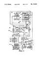
- FIG. 1is a block diagram of a refrigeration system incorporating the compressor system of the present invention.
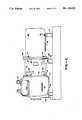
- FIGS. 2-7show how the compressor is coupled to motor in the preferred embodiment.
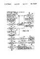
- FIG. 8is a flow chart of the main control program used in the preferred embodiment.
- FIG. 1there is shown a block diagram of a refrigeration system 20 with a continuously variable capacity compressor 22.
- the refrigeration system 20is typically used to refrigerate one or more cases 24 in a supermarket.
- the present inventionconcerns the compressor system 25, including the compressor 22 and its control mechanisms.
- the refrigeration system 20includes all the standard elements 26 of a standard commercial refrigeration system including a condenser 26, receiver 28, an evaporator 30, and a defrost mechanism.
- the condenser 26is air cooled by air from a fan 31.
- the refrigeration systemwill include a primary defroster 32, such as an electric coil defroster. If the system 20 includes more than one refrigeration case, there may be an auxiliary defroster 34 for defrosting cases which need to be defrosted more frequently than the other cases. If the system 20 does use hot gas defrost, it will typically have a hot gas valve 36 for routing hot refrigerant exiting the compressor 22 through the evaporator 30. In the preferred embodiment, the controller's defrost control software is tailored to fit the type of defrost being used.
- the compressor 22includes a reciprocating compressor 42 coupled to a variable speed drive motor 44 by an open direct drive arrangement 46 which is described in more detail below with reference to FIGS. 2-7.
- the drive motor 44can be driven at any specified speed within a predefined range, such as 450 to 1800 rpms, by an inverter 48.
- the inverter 48drives the motor 44 by converting a standard three phase power source into a three phase power source 50 which oscillates at a specified frequency.
- the inverter's output frequencyis specified by a control signal on line 52.
- the control signalis a current signal in which the specified frequency, FHZ, is equal to (Icntrl-4)*60/16, where Icntrl is the control signal's current measured in milliamps.
- the inverter 48is programmed to monitor the current and voltage waveforms on the drive line 50, and to adjust the drive voltage until the power delivered to the motor matches its load. In addition, the inverter 48 generates two feedback signals: a motor speed feedback signal which indicates the actual speed of the motor 44 (which may be different from the specified speed because of slippage or other problems) and an inverter fault signal which becomes active only if the inverter suffers a serious fault.
- the motorwill turn at a specified multiple (e.g., thirty) of the power source frequency.
- a specified multiplee.g., thirty
- an inverter frequency of fifteen hertzcorresponds to a motor speed of 450 rpms
- an inverter frequency of 60 hertzcorresponds to a motor speed of 1800 rpms.
- the control signal Icntrl on line 52specifies a motor speed:
- MXis the speed/frequency conversion factor
- the inverters used in the preferred embodiments to power the motorare Yaskawa 200 series inverters (which accept three phase input power at 185 to 280 volts and 50 or 60 cycles per second, and Yaskawa 400 series inverters (which accept three phase input power at 295 to 595 volts and 50 or 60 cycles per second).
- the control software in the invertershas been modified to adjust the drive voltage as described above.
- the compressor's controller 40is a computerized controller which monitor's the temperature in the applications (typically refrigeration cases) 24 and/or the suction pressure in the compressor's suction line 54, and adjusts the speed of the motor 44 in accordance with the difference between the temperature or pressure and a specified target value.
- the core of the controller 40is a small computer 56, using a microprocessor (e.g., the INTEL 8088) for its central processing unit.
- the computer 56receives input signals indicative of the state of the system 20 from its input interface 58.
- Outputs from the computer 56, which control the defrosters 32 and 34, the condenser fan 31, and the motor speed,are routed through and buffered by an output interface 60.
- the input interface 58includes a standard eight bit analog to digital converter (not shown) which converts analog measurement signals into corresponding digital values.
- the analog inputsinclude: a temperature signal from temperature probe 60 which is converted into a digital value called measured temp: a suction pressure signal from pressure gauge 62, which is converted into a digital value called suction pressure; a discharge pressure signal from pressure gauge 64 which is converted into a digital value called discharge pressure; and a motor speed feedback signal on line 66 from the inverter 48 which is converted into a digital value called motor speed.
- the input interface 66also receives two logical signals: a fault signal from the inverter 48, and a signal indicating a low oil condition in the compressor apparatus 22.
- the computer 56is coupled to a modem 68 so that status information can be sent to remote locations by telephone line 70.
- a new table of operating parameter valuescan be downloaded from a remote computer through the modem 68, and if necessary, a complete new set of control programs can be downloaded into the system's memory 72.
- the system's memory 72includes battery backed up static RAM 74 (random access memory), and also ROM 76 (read only memory).
- the system's control softwareis stored in the ROM 76, but new versions can downloaded and stored in the RAM 74. If the RAM version is lost or corrupted (e.g., fails a checksum test), the version in the ROM can be used until a new copy of the current version is downloaded through the modem 68.
- the RAM 74is also used to store a table 74a of operating parameters, which define how the controller 40 is to work with the particular application 26 connected to the controller 40.
- the preferred embodimentuses a backlight eight line LCD display 80 to display the system's status, and to display the current function of the key 82 at the bottom of the display. Using these keys, the user can flip through a series of different control and status menus and displays to review the status of the system 20, and to change parameter values in the parameter tables 74a.
- the controller 40also uses a buzzer 84 to denote the occurrence of problems which require immediate attention.
- a watchdog circuit 86monitor's activity on one of the computer's ports. If no activity is detected in a predefined period of time (typically 0.5 seconds), the watchdog circuit 86 generates signals which reset the computer 56, and which activate the system's mechanical backup circuitry 88.
- the mechanical backup circuitry 88ensures that the compressor motor continues to run even if the controller 40 fails, so that the product in the refrigeration cases 24 will be preserved while the controller is being repaired.
- FIG. 2there is shown a plan view of a compressor 42, a drive motor 44, and the coupling sleeve 46 therebetween.
- the compressor 42is a reciprocating open drive compressor.
- the compressorhas two cylinders and four cylinders.
- Gas entering the compressor at inlet 102can range from -127° F. to 85° F.
- the motor 44is a standard NEMA D-flang motor.
- the motors used in the preferred embodimentsinclude motors made Baldor (models 36F563W932 (5 horsepower), 37E778X118 (7.5 hp), and 37E778X234 (10 hp), and similar capacity motors made by Marathon.
- the compressor's housinghas a mounting base 104 through which two bolts 106 (one on each side of the compressor) can be inserted for supporting the compressor on platform 107 at a fixed location.
- the motor 44also has a mounting base 108 through which bolts 110 can be inserted for supporting the motor 44 on a platform 112.
- the coupling sleeve 46also called a bell housing, is disengageably connected to both the compressor 42 and the motor 44 by bolts 114 and 116 which couple the flanges 118 and 120 on each end of the sleeve to corresponding flanges 122 and 124 on the motor and compressor.
- the sleeve 46has a cylindrical interior, and two feet 126 (one on each side of the assembly) which can be bolted to a platform 128. While the sleeve is mostly closed to prevent extraneous objects from entering the sleeve, the sleeve has apertures 130 through which a socket wrench can be inserted for tightening and loosing the bolts 116 which connect the sleeve 46 to the compressor 42.
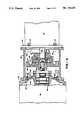
- FIG. 3there is shown a cross section of the compressor 42, motor 44 and coupling sleeve 46.
- the compressor's input shaft 140 and the drive motor's drive shaft 142are connected by a coupling arrangement 145 including two coupling members 146 and 148. The manner in which these two coupling members interlock will be discussed below with reference to FIGS. 4 through 7.
- the first coupling member 146is carried by the drive shaft 142 of the motor, and the second coupling member 148 is carried by the input shaft 140 of the compressor. These coupling members are interlocked in an unconnected manner with one another so that the output shaft 142 of the motor 44 drives the input shaft 140 of the compressor 42.
- the coupling member 146 on the motor shaft 142is a standard, motor coupling which clamps onto the motor shaft using a locked bolt bushing.
- the shaft 152 and coupling member 146have at least one corresponding straight key 147 and key slot 151 for transferring torque from the drive shaft 142 to the motor coupling 146.
- the coupling member 148 connected to the compressor shaft 140is a single piece of casted aluminum in the form of a flywheel which acts not only as a coupling member, but also acts as a flywheel which absorbs inertia from the compressor, reduces vibrations in the compressor, and reduces the stress placed on the compressors bearing's 149 by changing loads and motor speeds.
- the flywheel 148is coupled to the compressor's tapered shaft 140 by a single standard SAE threaded bolt 150 which threads into a threaded hole 152 in the shaft.
- the bolt 150holds a washer 154 against the flywheel 148, thereby securing the flywheel to the compressor shaft.
- the flywheelalso has a slot 156 that slides over a woodruff key 158 for transferring torque from the flywheel 148 to the input shaft 140.
- each flywheel 148is balanced on a lathe to match the compressor that it being used with.
- the sleeve 46is connected to the motor 44 by a set of four bolts 114 which go through a standard D flange 122 in the motor's housing into corresponding bosses 114a in the sleeve's flange 118.
- the sleevesits on a locating shoulder 160 machined into the compressor's housing, and is held in place by a set of bolts 116 which go through a flange 120 on the inside of the sleeve 46 into corresponding bosses 116a in the compressor's housing. Access to these bolts 116 is provided by apertures 130 shown in FIG. 2.
- the sleeve 46is made of aluminum and is strong enough to support the motor 44 in a fixed position relative to the compressor for maintaining the drive shaft 142 of the motor in alignment with the input shaft 140 of the compressor when the coupling members 146 and 148 are interlocked with one another.
- the sleeve 46is the sole means for supporting the motor so as to maintain the shafts in alignment with one another. Alignment of the two shafts takes place simply by bolting the sleeve to the compressor and motor with the flywheel and motor coupling assembly 145 inside. The sleeve bolts themselves assure proper alignment.
- FIG. 4shows the components of the coupling arrangement separated from one another along the center axis of the shafts 140 and 142. This Figure also shows the placement of the cut away views in FIGS. 5 through 7.
- both coupling members 148 and 146have three spaced apart lugs 148a and 146a which interlock with the lugs on the other coupling member.
- lugs on the interlocking coupling membersare separated by a nonmetallic, compressible webbing 160 (shown in FIG. 7), made from a standard chloroprene compound used in webbed motor couplings, which prevents direct metal to metal contact by the lugs, and absorbs shocks and transient torque imbalances.
- the webbing 160has six teeth 162 which fit snugly between the lugs on both couplings.
- FIG. 8is a flow chart of the control software used in the preferred embodiment.
- Appendix 1 at the end of this descriptioncontains a pseudocode representation of the main routine used in the preferred embodiment, and shows more details of the process than shown in FIG. 8.
- Appendices 2-8 at the end of this descriptioncontain pseudocode representations of the software subroutines relevant to the present invention.
- the pseudocode used in these appendicesis, essentially, a computer language using universal computer language conventions. While the pseudocode employed here has been invented solely for the purposes of this description, it is designed to be easily understandable to any computer programmer skilled in the art.
- the computer programs in the preferred embodimentare written in the "C” computer language, and in the assembly language for the (Intel model 8088) microprocessor used therein.
- the controllercontinually performs the main loop of the control software, shown as starting at node A in FIG. 8.
- the execution time of the main loopvaries between 0.25 and 1.5 seconds, depending on the tasks performed.
- the initial tasksinclude handling keystrokes entered by the operator, updating the display, responding to communications from a host computer (i.e., communications tasks), and signalling the watchdog circuit 86 that the controller 40 is operational. Then the controller executes the compressor motor control software, starting at box 204.
- each refrigeration system 26may have somewhat different equipment or operating conditions. To tailor the controller to each application, the user specifies the set of parameters shown in Table 1. While these parameters will be discussed as they are used, some affect the overall operation of the controller.
- the parameter called "Temp.Enabled”indicates whether a temperature measurement is available for use by the controller. Since it is the goal of the controller to maintain a target temperature (called Setpt.Temp) in the application, it is clearly preferred that the system include a temperature sensor 60.
- UsePressureAnother important parameter is called UsePressure. As will be described with reference to Appendices 5 and 8, if Temp.Enabled is false or if UsePressure is true, the controller will control the speed of the compressor's motor using an algorithm based on the pressure in the compressor's suction line. Otherwise, it will use an algorithm based on the temperature in the application. However, if both Temp.Enabled and UsePressure are true, the controller will use an algorithm that is primarily based on the suction pressure, but which floats the target pressure in accordance with the temperature in the application. Thus the controller has three different control strategies which it can use.
- the controller 40includes an interrupt generator 90 which generates an interrupt signal 120 times per second, at the peaks and valleys of the waveform of the system's 60 hertz power supply. Each interrupt signal causes the system to run the analog signal input routine shown in Appendix 4.
- the analog signal input routinereads in, and keeps running averages of the temperature, suction pressure, discharge pressure, and motor speed feedback signals. These signals are converted into digital signals by the input interface 58.
- the analog input routineincludes a schedule which controls which input signal is to be sampled and converted by the analog to digital converter in the interface 58 during each interrupt period.
- each cycle of sixteen interrupt callsit averages the value of each input signal measured at the time of a power waveform peak and at the time of a power waveform valley. It then computes a running average for each signal to reduce the effect of transient signal fluctuations.
- temperatureis measured to an accuracy of 0.25° F.
- pressureis measured to an accuracy of 0.5 psi (pounds per square inch).
- the analog input routinealso acts as a timer routine which updates the "elapsed time” timer. This elapsed timer is used throughout the control program for various time checks.
- the motor control softwarestarts (at box 204) by checking for serious faults.
- the fault checking routineshown in Appendix 2, checks for the following faults; (1) is the discharge pressure above a specified limit "discharge.max, (2) is the suction pressure below a specified value “suction.min”, (3) is the measured temperature above or below specified limits “case.temp.max” and “cause.temp.min”, (4) is the motor speed feedback signal more than fifteen percent off from the specified speed, (5) is the motor oil fault signal active, and (6) is the inverter fault signal active.
- the erroris logged in the system's memory 72, noted on the display 80, and the system switches to mechanical mode--so that the mechanical backup system will take over control of the system.
- the displayAfter checking for faults, the display is updated so that any problems detected will be shown on the display. Serious faults are also denoted by activating the buzzer 84.
- Condenser Fan ControlIf the system is still in automatic mode, the condenser fan 31 is turned on if the discharge pressure is above FanCutIn, and is turned off if the discharge pressure is below FanCutOut. This sample fan control method saves a significant amount of energy in most air cooled systems when compared to the prior art.
- the Coldstart processhas three phases, First (after waiting for a defrost cycle to end, if necessary) the motor is turned on at a specified speed, CycleOn, which is typically an intermediate speed such as 750 rpms. Then, after a minute or so the controller checks that the motor speed is ramping up to the specified speed. If at the end of a specified time the motor is not within a specified margin of the CycleOn speed, the motor is shut off and the controller activates the mechanical backup system.
- CycleOntypically an intermediate speed such as 750 rpms.
- the controllerwaits for another short period of time, tests to see if the temperature, suction pressure and discharge pressure have moved in right direction since the beginning of the Coldstart process, and returns control to the normal control routine.
- Check Defrost Schedule(Box 212) The user can schedule up to six different times at which to start a primary defrost, and up to six other times at which to start the auxiliary defrost.
- the Check.Defrost routineshown in Appendix 3, checks these schedules. If the current time corresponds to the schedule start of a primary defrost, the primary defrost is turned on, the compressor motor is turned off, the controller's state is set to DEFROST, and the auxiliary defrost is also turned on if there is an auxiliary defrost.
- Scheduled auxiliary defrostsare different in that only the auxiliary defrost is turned on and the controller does not change operating states. Also, since auxiliary defrosts run for a specified time, this routine also turns off the auxiliary defrost at the scheduled termination time.
- the motor speedis adjusted only at specified intervals (box 214). If the time since the last execution of the motor speed adjustment process is less than SampleTime seconds, the process goes back to node A.
- the sample time intervaldepends on the control strategy being used. For temperature based control, the interval is typically fifteen to thirty seconds; for pressure based control, the sample time interval is typically three to ten seconds.
- Defrost TerminationIf the controller is in the DEFROST of the defrost termination criteria have been met (box 218). There are three different criteria which can be used: a maximum defrost duration, a maximum suction line pressure, and a maximum case temperature. If defrost is not terminated, the motor is left off and the process goes back to node A.
- the controllerturns on the motor at full speed (called Design.hz), sets its state to POSTDEFROST (box 220) and returns to node A.
- POSTDEFROSTThe purpose of POSTDEFROST is to pull the application temperature back down to normal as quickly as possible.
- PostDefrostThe controller remains in POSTDEFROST for at least a specified minimum time, Min. PostDefrost.Time. Then POSTDEFROST is terminated, and the controller's state is set to RESCTL (short for "restore control"), if (1) the temperature falls below a specified temperature above the target temperature; (2) the suction pressure falls below a specified suction pressure above the target suction pressure, (3) or the elapsed time is POSTDEFROST exceeds a specified time. Otherwise, the controller stays in POSTDEFROST with the motor running at full speed. POSTDEFROST is terminated before the temperature and/or pressure reach their target values so that the system will smoothly reach its target rather than overshooting the target temperature and/or pressure.
- RESCTLshort for "restore control”
- CycleOff TerminationIf the compressor's capacity exceeds the load even when running at its minumum speed, the controller will shut down the motor and set the state to CYCLEOFF (see boxes 236 and 238). Once the motor is shut off, it is kept off for at least a specified time, Min.Time.Off, to prevent the compressor from being cycled off and on too quickly. Then controller will turn the motor back at a specified speed, CycleOn, and set the state to CYCLEON if (box 228 to 230): the temperature rises above its target level, the suction pressure rises above its target level, or the elapsed time in CYCLEOFF exceeds a specified maximum, Max. Time.Off.
- the motor speed adjustment procedure(box 234), called PID and shown in detail in Appendices 5 and 8, is executed. This procedure is called PID because the motor speed adjustment is based on three factors, one which is Proportional to an error signal, one which is the Integral of the error signal, and one which is the derivative of the error signal.
- the error signal usedis the difference between the measured suction pressure and the pressure set point Setpt.Sp. Otherwise the error signal used is the difference between the measured temperature and the temperature set point Setpt.Temp.
- the error signalis numerically integrated and differentiated and a speed adjustment is calculated:
- ⁇ Sis the different between the measured temperature or pressure and its corresponding target value.
- Kp, Kd and Kiare constant parmeters.
- One set of parameter valuesis used for temperature based control, and another is used for pressure based controol.
- d ⁇ S/dtis the rate of change in the error signal ⁇ S
- ⁇ S dtis the integral of ⁇ S over a specified period of time.
- Range.hz.maxis the multiple used to convert the computed PID error to a speed adjustment.
- a temperature based strategyIn the preferred embodiment there are actually three control strategies: a temperature based strategy, a pressure based strategy, and one which uses both temperature and pressure.
- the third strategycomes into play if both Temp.Enabled and UsePressure are true.
- the pressure control algorithmis used, but the target pressure is periodically (typically once every few minutes) increased if the measured temperature is below the target deadband, and decreased if the measured temperature is above the target deadband.
- the pseudocode for this processis shown in Appendix 8.
- the motor speedis not changed if the error signal falls within a specified target deadband--on the basis that if the system is on target, it should be left along as long as possible.
- the new motor speedis (1) not allowed to increase at more than a specified rate not to decrease at more than a specified rate--to prevent unnecessary motor speed fluctuations, and (2) is kept within its specified limits, MinSpeed and Design.hz.
- the controlleruses additional logic when the motor runs at its specified minimum speed (e.g. 450 rpms).
- the controllerkeeps the motor running at this minimum speed as long as the temperature or pressure remains within a specified deadband. But is the pressure falls below a specified low limit, or if the temperature and pressure fall below the deadband for at least a specified period of time (min.Speed.Time, e.g., 10 minutes) the controller will turn off the compressor and enter the CYCLEOFF state.
Landscapes
- Engineering & Computer Science (AREA)
- General Engineering & Computer Science (AREA)
- Mechanical Engineering (AREA)
- Physics & Mathematics (AREA)
- Thermal Sciences (AREA)
- Computer Hardware Design (AREA)
- Devices That Are Associated With Refrigeration Equipment (AREA)
- Control Of Positive-Displacement Pumps (AREA)
Abstract
Description
Specified motor speed=MX*(Icntrl-4)*60/16
If--conditions----statement--.
______________________________________ If condition- block of statements- Else optional block statements- optional Endif ______________________________________
err=Kp*((Kd*dΔS/dr)+(Ki∫ΔS dt)+ΔS)
speed.chage=err*range.hz.max
new motor speed=previous motor speed+speed.change
TABLE 1 ______________________________________ PARAMETERS SPECIFIED BY USER PARAMETER DESCRIPTION ______________________________________ Temp/Pressure Control Temp.sub.-- Enabled Flag - specifies if controller can use temperature measurements UsePressure Flag - use pressure to control motor speed Sample.sub.-- Time Time between motor speed adjustments: typically 30 seconds for temperature control 5 seconds for pressure control Delta.sub.-- TF Time between adjustments of target suction pressure Set Points Setpt.sub.-- Temp Target Temperature Setpt.sub.-- Sp Target suction pressure Suction Pressure Delta.sub.-- High Pressure above setpt at which motor if forced to run at its maximum speed Delta.sub.-- Cutin Pressure above setpt at which system turns motor back on Delta.sub.-- Cutout Pressure below setpt at which motor is forced to run at minimum speed Delta.sub.-- Low Pressure below setpt at which motor will be shut off Suction.sub.-- Min Fault limit Discharge Pressure Discharge.sub.-- Max Fault limit FanCutIn Condenser pressure at which fan is turned on FanCutOut Condenser pressure at which fan is turned off Motor Speeds Design.sub.-- Hz Maximum motor speed Cycleon.sub.-- Speed Motor speed when system cycles on Min.sub.-- Speed Minimum motor speed Slowdown.sub.-- Rate Normal maximum rate at which motor speed can be decreased Speedup.sub.-- Rate Normal maximum rate at which motor speed can be increased Defrost P.sub.-- Defrost.sub.-- Starttime (6) Primary Defrost start times A.sub.-- Defrost.sub.-- Starttime (6) Auxiliary Defrost start times Termination.sub.-- Pressure Suction pressure limit for Primary defrost (typically 60 to 80 lbs) Termination.sub.-- Temperature Case temperature limit Defrost.sub.-- Max.sub.-- Duration Maximum length of primary defrost Aux.sub.-- Defrost.sub.-- Duration Duration of auxiliary defrost Postdefrost Min.sub.-- PostDefrost.sub.-- Time Minimum duration of post defrost Max.sub.-- PostDefrost.sub.-- Time Maximum duration of post defrost Delta.sub.-- PullDown.sub.-- T Terminate Postdefrost if temp = Setpt + Delta.sub.-- Pulldown.sub.-- T Delta.sub.-- PullDown.sub.-- P Terminate Postdefrost if pressure = Setpt + Delta.sub.-- Pulldown.sub.-- P CycleOff Min.sub.-- Time.sub.-- Off Minimum time that motor is kept off once it is turned off Max.sub.-- Time.sub.-- Off Maximum time that motor is kept off during CYCLEOFF Cycle.sub.-- Temp.sub.-- Delta Terminate CycleOff if temp = Setpt + Cycle.sub.-- Temp.sub.-- Delta Alarm Limits discharge.sub.-- max Maximum discharge pressure hp.sub.-- max Duration of maximum discharge pressure before alarm suction.sub.-- min Minimum suction pressure sp.sub.-- max Duration of minimum suction pressure before alarm ms.sub.-- max Duration of motor speed error before alarm Case.sub.-- Temp.sub.-- Max Maximum case temperature Case.sub.-- Temp.sub.-- Min Minimum case temperature temp.sub.-- cat.sub.-- max Duration of case temp error before alarm PID - Motor Speed temp.sub.-- range Temperature divisor in control equations Sp.sub.-- Range Pressure divisor in control equations Kp, Kd, Ki PID coefficients range.sub.-- hz.sub. -- max Multiple for motor speed adjustments Deadband.sub.-- T Temperature deadband in which motor speed is not changed Deadband.sub.-- P Pressure deadband in which motor speed is not changed MinSpeed Min.sub.-- Speed.sub.-- Time Maximum time motor is kept at min.sub.-- speed before turn off unless suction pressure is too low Coldstart Rampup Duration of rampup before checking to see if system is responding - typically 2 minutes Max.sub.-- Speed.sub.-- Dif Maximum tolerable motor speed error Rampup2 Duration that system is checked for reasonable response (typically 3 minutes) Min.sub.-- Tchange Minimum required temperature response Min.sub.-- Pchange Minimum required suction pressure response Min.sub.-- Dchange Minimum required discharge pressure response ______________________________________ ##SPC1##
Claims (21)
(Kd*dΔT/dt)+(Ki∫Δdt)+ΔT
(Kd*dΔP/dt)+(Ki∫ΔP dt)
(Kd*dΔS/dt)+(Ki∫ΔSdt)+ΔS
(Kd*dΔT/dt)+(Ki∫ΔT dt)+ΔT
(Kd*dΔT/dt)+(Ki∫ΔT dt)+ΔT.
(Kd*dΔT/dt)+(Ki∫ΔT dt)+ΔT
(Kd*dΔT/dt)+(Ki∫ΔT dt)+ΔT.
(Kd*dΔT/dt)+(Ki∫ΔT dt)+ΔT
(Kd*dΔT/dt)+(Ki∫ΔT dt)+ΔT.
(Kd*dΔP/dt)+(Ki∫ΔP dt)+ΔP
(Kd*dΔP/dt)+(Ki∫ΔP dt)+ΔP.
(Kd*dΔP/dt)+(Ki∫ΔP dt)+ΔP
(Kd*dΔP/dt)+(Ki∫ΔP dt) +ΔP.
(Kd*dΔP/dt)+(Ki∫ΔP dt)+ΔP
(Kd*dΔP/dt)+(Ki∫ΔP dt)+ΔP.
(Kd*dΔS/dt)+(Ki∫ΔS dt)+ΔS
(Kd*dΔS/dt)+(Ki∫ΔS dt)+ΔS.
(Kd*dΔS/dt)+(Ki∫ΔS dt)+ΔS.
(Kd*dΔS/dt)+(Ki∫ΔS dt)+ΔS
(Kd*dΔS/dt)+(Ki∫ΔS dt)+ΔS.
Priority Applications (1)
| Application Number | Priority Date | Filing Date | Title |
|---|---|---|---|
| US07/356,380USRE33620E (en) | 1987-02-09 | 1989-05-23 | Continuously variable capacity refrigeration system |
Applications Claiming Priority (2)
| Application Number | Priority Date | Filing Date | Title |
|---|---|---|---|
| US07/012,578US4765150A (en) | 1987-02-09 | 1987-02-09 | Continuously variable capacity refrigeration system |
| US07/356,380USRE33620E (en) | 1987-02-09 | 1989-05-23 | Continuously variable capacity refrigeration system |
Related Parent Applications (1)
| Application Number | Title | Priority Date | Filing Date |
|---|---|---|---|
| US07/012,578ReissueUS4765150A (en) | 1987-02-09 | 1987-02-09 | Continuously variable capacity refrigeration system |
Publications (1)
| Publication Number | Publication Date |
|---|---|
| USRE33620Etrue USRE33620E (en) | 1991-06-25 |
Family
ID=26683737
Family Applications (1)
| Application Number | Title | Priority Date | Filing Date |
|---|---|---|---|
| US07/356,380Expired - LifetimeUSRE33620E (en) | 1987-02-09 | 1989-05-23 | Continuously variable capacity refrigeration system |
Country Status (1)
| Country | Link |
|---|---|
| US (1) | USRE33620E (en) |
Cited By (45)
| Publication number | Priority date | Publication date | Assignee | Title |
|---|---|---|---|---|
| US5440891A (en)* | 1994-01-26 | 1995-08-15 | Hindmon, Jr.; James O. | Fuzzy logic based controller for cooling and refrigerating systems |
| US5746062A (en)* | 1996-04-11 | 1998-05-05 | York International Corporation | Methods and apparatuses for detecting surge in centrifugal compressors |
| US6202431B1 (en) | 1999-01-15 | 2001-03-20 | York International Corporation | Adaptive hot gas bypass control for centrifugal chillers |
| US6206643B1 (en)* | 1998-06-17 | 2001-03-27 | Samsung Electronics Co., Ltd. | Method for controlling reciprocating compressor having variable capacity |
| US20030205053A1 (en)* | 2001-08-22 | 2003-11-06 | Mark Lane | Service case |
| EP1213501A3 (en)* | 2000-12-05 | 2004-08-25 | VARVEL S.p.A. | Connecting device between a shaft of a motor and a speed reducer |
| US20050160749A1 (en)* | 2004-01-23 | 2005-07-28 | Shaffer Dennis L. | Enhanced manual start/stop sequencing controls for a steam turbine powered chiller unit |
| US20050217310A1 (en)* | 2004-04-01 | 2005-10-06 | Luehrs Frederick G | Refrigeration system and components thereof |
| US7065979B2 (en) | 2002-10-30 | 2006-06-27 | Delaware Capital Formation, Inc. | Refrigeration system |
| US20060230768A1 (en)* | 2005-04-14 | 2006-10-19 | Ranco Incorporated Of Delaware | Universal defrost timer |
| US20070050221A1 (en)* | 2005-08-29 | 2007-03-01 | Abtar Singh | Dispatch management model |
| US20070289323A1 (en)* | 2006-06-20 | 2007-12-20 | Delaware Capital Formation, Inc. | Refrigerated case with low frost operation |
| US7328587B2 (en) | 2004-01-23 | 2008-02-12 | York International Corporation | Integrated adaptive capacity control for a steam turbine powered chiller unit |
| US20080156009A1 (en)* | 2006-12-28 | 2008-07-03 | Whirlpool Corporation | Variable capacity modular refrigeration system for kitchens |
| US20080209921A1 (en)* | 2007-03-02 | 2008-09-04 | Dover Systems, Inc. | Refrigeration system |
| US7421854B2 (en) | 2004-01-23 | 2008-09-09 | York International Corporation | Automatic start/stop sequencing controls for a steam turbine powered chiller unit |
| US20080282719A1 (en)* | 2005-12-07 | 2008-11-20 | Fung Kwok K | Airflow Stabilizer for Lower Front of a Rear Loaded Refrigerated Display Case |
| US20090205351A1 (en)* | 2006-10-26 | 2009-08-20 | Kwok Kwong Fung | Secondary airflow distribution for a display case |
| US20100011793A1 (en)* | 2008-07-16 | 2010-01-21 | Charles John Tiranno | Refrigeration control system |
| US20100031697A1 (en)* | 2008-08-07 | 2010-02-11 | Dover Systems, Inc. | Modular co2 refrigeration system |
| US20100082160A1 (en)* | 2007-02-26 | 2010-04-01 | Naoshi Kondou | Refrigerating storage cabinet and control method for compressor thereof |
| US20100313588A1 (en)* | 2009-06-10 | 2010-12-16 | Hill Phoenix, Inc | Air distribution system for temperature-controlled case |
| US7878006B2 (en) | 2004-04-27 | 2011-02-01 | Emerson Climate Technologies, Inc. | Compressor diagnostic and protection system and method |
| US8160827B2 (en) | 2007-11-02 | 2012-04-17 | Emerson Climate Technologies, Inc. | Compressor sensor module |
| US8393169B2 (en) | 2007-09-19 | 2013-03-12 | Emerson Climate Technologies, Inc. | Refrigeration monitoring system and method |
| US8475136B2 (en) | 2003-12-30 | 2013-07-02 | Emerson Climate Technologies, Inc. | Compressor protection and diagnostic system |
| US8590325B2 (en) | 2006-07-19 | 2013-11-26 | Emerson Climate Technologies, Inc. | Protection and diagnostic module for a refrigeration system |
| US8964338B2 (en) | 2012-01-11 | 2015-02-24 | Emerson Climate Technologies, Inc. | System and method for compressor motor protection |
| US8974573B2 (en) | 2004-08-11 | 2015-03-10 | Emerson Climate Technologies, Inc. | Method and apparatus for monitoring a refrigeration-cycle system |
| US9140728B2 (en) | 2007-11-02 | 2015-09-22 | Emerson Climate Technologies, Inc. | Compressor sensor module |
| US9285802B2 (en) | 2011-02-28 | 2016-03-15 | Emerson Electric Co. | Residential solutions HVAC monitoring and diagnosis |
| US9310094B2 (en) | 2007-07-30 | 2016-04-12 | Emerson Climate Technologies, Inc. | Portable method and apparatus for monitoring refrigerant-cycle systems |
| US9310439B2 (en) | 2012-09-25 | 2016-04-12 | Emerson Climate Technologies, Inc. | Compressor having a control and diagnostic module |
| US9480177B2 (en) | 2012-07-27 | 2016-10-25 | Emerson Climate Technologies, Inc. | Compressor protection module |
| US9526354B2 (en) | 2008-09-11 | 2016-12-27 | Hill Phoenix, Inc. | Air distribution system for temperature-controlled case |
| US9541311B2 (en) | 2010-11-17 | 2017-01-10 | Hill Phoenix, Inc. | Cascade refrigeration system with modular ammonia chiller units |
| US9551504B2 (en) | 2013-03-15 | 2017-01-24 | Emerson Electric Co. | HVAC system remote monitoring and diagnosis |
| US9638436B2 (en) | 2013-03-15 | 2017-05-02 | Emerson Electric Co. | HVAC system remote monitoring and diagnosis |
| US9657977B2 (en) | 2010-11-17 | 2017-05-23 | Hill Phoenix, Inc. | Cascade refrigeration system with modular ammonia chiller units |
| US9664424B2 (en) | 2010-11-17 | 2017-05-30 | Hill Phoenix, Inc. | Cascade refrigeration system with modular ammonia chiller units |
| US9765979B2 (en) | 2013-04-05 | 2017-09-19 | Emerson Climate Technologies, Inc. | Heat-pump system with refrigerant charge diagnostics |
| US9823632B2 (en) | 2006-09-07 | 2017-11-21 | Emerson Climate Technologies, Inc. | Compressor data module |
| US10488090B2 (en) | 2013-03-15 | 2019-11-26 | Emerson Climate Technologies, Inc. | System for refrigerant charge verification |
| US20200171916A1 (en)* | 2018-12-03 | 2020-06-04 | Ford Global Technologies, Llc | A/c compressor control using refrigerant pressure |
| US11255581B2 (en)* | 2019-12-24 | 2022-02-22 | Twinbird Corporation | Free piston Stirling refrigerator |
Citations (33)
| Publication number | Priority date | Publication date | Assignee | Title |
|---|---|---|---|---|
| US3324672A (en)* | 1964-08-31 | 1967-06-13 | Gen Motors Corp | Electrically controlled conditioning system |
| US3449922A (en)* | 1967-02-01 | 1969-06-17 | John D Ruff | Centrifugal compressor and wide range of capacity variation |
| US3499297A (en)* | 1969-02-20 | 1970-03-10 | John D Ruff | Variable capacity refrigeration system |
| US3559422A (en)* | 1968-12-09 | 1971-02-02 | Holzer Patent Ag | Means for regulating the temperature of refrigerators |
| DE1939410A1 (en)* | 1969-08-02 | 1971-02-18 | Barth Harald | Elastic claw coupling |
| US3610781A (en)* | 1968-12-10 | 1971-10-05 | Bosch Gmbh Robert | Windshield wiper motor and pump assembly |
| US3668883A (en)* | 1970-06-12 | 1972-06-13 | John D Ruff | Centrifugal heat pump with overload protection |
| DE2323269A1 (en)* | 1973-05-09 | 1974-11-28 | Bosch Gmbh Robert | CONVEYOR UNIT FOR LIQUIDS |
| US4006603A (en)* | 1975-06-13 | 1977-02-08 | Vapor Corporation | Air conditioning system for a railway vehicle |
| US4015182A (en)* | 1974-06-24 | 1977-03-29 | General Electric Company | Refrigeration system and control therefor |
| US4177649A (en)* | 1977-11-01 | 1979-12-11 | Borg-Warner Corporation | Surge suppression apparatus for compressor-driven system |
| US4364237A (en)* | 1981-02-02 | 1982-12-21 | Borg-Warner Corporation | Microcomputer control for inverter-driven heat pump |
| US4407139A (en)* | 1980-10-13 | 1983-10-04 | Tokyo Shibaura Denki Kabushiki Kaisha | Method for controlling an air conditioning system |
| US4459519A (en)* | 1974-06-24 | 1984-07-10 | General Electric Company | Electronically commutated motor systems and control therefor |
| US4480442A (en)* | 1983-01-17 | 1984-11-06 | Tokyo Shibaura Denki Kabushiki Kaisha | Air conditioning system |
| US4484453A (en)* | 1982-10-08 | 1984-11-27 | Cf Industries, Inc. | Ammonia plant refrigeration system and process control method therefor |
| US4507058A (en)* | 1983-12-20 | 1985-03-26 | Carr-Griff, Inc. | Wobble plate pump and drive mechanism therefor |
| US4514991A (en)* | 1983-10-17 | 1985-05-07 | Carrier Corporation | Variable speed drive motor system with inverter control |
| US4546618A (en)* | 1984-09-20 | 1985-10-15 | Borg-Warner Corporation | Capacity control systems for inverter-driven centrifugal compressor based water chillers |
| DE3523818A1 (en)* | 1984-07-04 | 1986-01-09 | Kabushiki Kaisha Toshiba, Kawasaki, Kanagawa | AIR CONDITIONER |
| US4604036A (en)* | 1983-09-09 | 1986-08-05 | Hitachi, Ltd. | Torque control apparatus for enclosed compressors |
| US4622827A (en)* | 1983-12-28 | 1986-11-18 | Matsushita Electric Industrial Co., Ltd. | Control apparatus for an air conditioner |
| US4628700A (en)* | 1979-07-31 | 1986-12-16 | Alsenz Richard H | Temperature optimizer control apparatus and method |
| US4646534A (en)* | 1985-07-15 | 1987-03-03 | Earl Russell | Means for refrigeration speed control |
| US4658596A (en)* | 1984-12-01 | 1987-04-21 | Kabushiki Kaisha Toshiba | Refrigerating apparatus with single compressor and multiple evaporators |
| US4662185A (en)* | 1985-03-04 | 1987-05-05 | Hitachi, Ltd. | System of controlling refrigerator temperature |
| GB2183018A (en)* | 1985-10-28 | 1987-05-28 | Toshiba Kk | Multi-type air conditioner with optimum control for each load |
| US4676073A (en)* | 1985-06-11 | 1987-06-30 | Carl Lawrence | Cooling apparatus |
| US4706470A (en)* | 1985-05-16 | 1987-11-17 | Sawafuji Electric Co., Ltd. | System for controlling compressor operation |
| US4720981A (en)* | 1986-12-23 | 1988-01-26 | American Standard Inc. | Cooling of air conditioning control electronics |
| US4724680A (en)* | 1985-11-28 | 1988-02-16 | Kabushiki Kaisha Toshiba | Air conditioning apparatus and control method thereof |
| US4736595A (en)* | 1986-02-03 | 1988-04-12 | Hitachi, Ltd. | Circuit for controlling inventer in air conditioner |
| US4748822A (en)* | 1986-12-04 | 1988-06-07 | Carrier Corporation | Speed control of a variable speed air conditioning system |
- 1989
- 1989-05-23USUS07/356,380patent/USRE33620E/ennot_activeExpired - Lifetime
Patent Citations (35)
| Publication number | Priority date | Publication date | Assignee | Title |
|---|---|---|---|---|
| US3324672A (en)* | 1964-08-31 | 1967-06-13 | Gen Motors Corp | Electrically controlled conditioning system |
| US3449922A (en)* | 1967-02-01 | 1969-06-17 | John D Ruff | Centrifugal compressor and wide range of capacity variation |
| US3559422A (en)* | 1968-12-09 | 1971-02-02 | Holzer Patent Ag | Means for regulating the temperature of refrigerators |
| US3610781A (en)* | 1968-12-10 | 1971-10-05 | Bosch Gmbh Robert | Windshield wiper motor and pump assembly |
| US3499297A (en)* | 1969-02-20 | 1970-03-10 | John D Ruff | Variable capacity refrigeration system |
| DE1939410A1 (en)* | 1969-08-02 | 1971-02-18 | Barth Harald | Elastic claw coupling |
| US3668883A (en)* | 1970-06-12 | 1972-06-13 | John D Ruff | Centrifugal heat pump with overload protection |
| DE2323269A1 (en)* | 1973-05-09 | 1974-11-28 | Bosch Gmbh Robert | CONVEYOR UNIT FOR LIQUIDS |
| US4459519A (en)* | 1974-06-24 | 1984-07-10 | General Electric Company | Electronically commutated motor systems and control therefor |
| US4015182A (en)* | 1974-06-24 | 1977-03-29 | General Electric Company | Refrigeration system and control therefor |
| US4006603A (en)* | 1975-06-13 | 1977-02-08 | Vapor Corporation | Air conditioning system for a railway vehicle |
| US4177649A (en)* | 1977-11-01 | 1979-12-11 | Borg-Warner Corporation | Surge suppression apparatus for compressor-driven system |
| US4628700A (en)* | 1979-07-31 | 1986-12-16 | Alsenz Richard H | Temperature optimizer control apparatus and method |
| US4407139A (en)* | 1980-10-13 | 1983-10-04 | Tokyo Shibaura Denki Kabushiki Kaisha | Method for controlling an air conditioning system |
| US4364237A (en)* | 1981-02-02 | 1982-12-21 | Borg-Warner Corporation | Microcomputer control for inverter-driven heat pump |
| US4484453A (en)* | 1982-10-08 | 1984-11-27 | Cf Industries, Inc. | Ammonia plant refrigeration system and process control method therefor |
| US4480442A (en)* | 1983-01-17 | 1984-11-06 | Tokyo Shibaura Denki Kabushiki Kaisha | Air conditioning system |
| US4604036A (en)* | 1983-09-09 | 1986-08-05 | Hitachi, Ltd. | Torque control apparatus for enclosed compressors |
| US4514991A (en)* | 1983-10-17 | 1985-05-07 | Carrier Corporation | Variable speed drive motor system with inverter control |
| US4507058A (en)* | 1983-12-20 | 1985-03-26 | Carr-Griff, Inc. | Wobble plate pump and drive mechanism therefor |
| US4622827A (en)* | 1983-12-28 | 1986-11-18 | Matsushita Electric Industrial Co., Ltd. | Control apparatus for an air conditioner |
| US4738118A (en)* | 1984-07-04 | 1988-04-19 | Kabushiki Kaisha Toshiba | Air conditioner |
| DE3523818A1 (en)* | 1984-07-04 | 1986-01-09 | Kabushiki Kaisha Toshiba, Kawasaki, Kanagawa | AIR CONDITIONER |
| US4546618A (en)* | 1984-09-20 | 1985-10-15 | Borg-Warner Corporation | Capacity control systems for inverter-driven centrifugal compressor based water chillers |
| US4658596A (en)* | 1984-12-01 | 1987-04-21 | Kabushiki Kaisha Toshiba | Refrigerating apparatus with single compressor and multiple evaporators |
| US4662185A (en)* | 1985-03-04 | 1987-05-05 | Hitachi, Ltd. | System of controlling refrigerator temperature |
| US4706470A (en)* | 1985-05-16 | 1987-11-17 | Sawafuji Electric Co., Ltd. | System for controlling compressor operation |
| US4676073A (en)* | 1985-06-11 | 1987-06-30 | Carl Lawrence | Cooling apparatus |
| US4646534A (en)* | 1985-07-15 | 1987-03-03 | Earl Russell | Means for refrigeration speed control |
| GB2183018A (en)* | 1985-10-28 | 1987-05-28 | Toshiba Kk | Multi-type air conditioner with optimum control for each load |
| US4720982A (en)* | 1985-10-28 | 1988-01-26 | Kabushiki Kaisha Toshiba | Multi-type air conditioner with optimum control for each load |
| US4724680A (en)* | 1985-11-28 | 1988-02-16 | Kabushiki Kaisha Toshiba | Air conditioning apparatus and control method thereof |
| US4736595A (en)* | 1986-02-03 | 1988-04-12 | Hitachi, Ltd. | Circuit for controlling inventer in air conditioner |
| US4748822A (en)* | 1986-12-04 | 1988-06-07 | Carrier Corporation | Speed control of a variable speed air conditioning system |
| US4720981A (en)* | 1986-12-23 | 1988-01-26 | American Standard Inc. | Cooling of air conditioning control electronics |
Cited By (93)
| Publication number | Priority date | Publication date | Assignee | Title |
|---|---|---|---|---|
| US5440891A (en)* | 1994-01-26 | 1995-08-15 | Hindmon, Jr.; James O. | Fuzzy logic based controller for cooling and refrigerating systems |
| US5746062A (en)* | 1996-04-11 | 1998-05-05 | York International Corporation | Methods and apparatuses for detecting surge in centrifugal compressors |
| US5894736A (en)* | 1996-04-11 | 1999-04-20 | York International Corporation | Methods and apparatuses for detecting surge in centrifugal compressors |
| US6206643B1 (en)* | 1998-06-17 | 2001-03-27 | Samsung Electronics Co., Ltd. | Method for controlling reciprocating compressor having variable capacity |
| US6691525B2 (en) | 1999-01-15 | 2004-02-17 | York International Corporation | Hot gas bypass control for centrifugal chillers |
| US6202431B1 (en) | 1999-01-15 | 2001-03-20 | York International Corporation | Adaptive hot gas bypass control for centrifugal chillers |
| US6427464B1 (en) | 1999-01-15 | 2002-08-06 | York International Corporation | Hot gas bypass control for centrifugal chillers |
| EP1213501A3 (en)* | 2000-12-05 | 2004-08-25 | VARVEL S.p.A. | Connecting device between a shaft of a motor and a speed reducer |
| US20030213260A1 (en)* | 2001-08-22 | 2003-11-20 | Mark Lane | Service case |
| US6883343B2 (en) | 2001-08-22 | 2005-04-26 | Delaware Capital Formation, Inc. | Service case |
| US6889514B2 (en) | 2001-08-22 | 2005-05-10 | Delaware Capital Formation, Inc. | Service case |
| US20030205053A1 (en)* | 2001-08-22 | 2003-11-06 | Mark Lane | Service case |
| US7065979B2 (en) | 2002-10-30 | 2006-06-27 | Delaware Capital Formation, Inc. | Refrigeration system |
| US8475136B2 (en) | 2003-12-30 | 2013-07-02 | Emerson Climate Technologies, Inc. | Compressor protection and diagnostic system |
| US20050160749A1 (en)* | 2004-01-23 | 2005-07-28 | Shaffer Dennis L. | Enhanced manual start/stop sequencing controls for a steam turbine powered chiller unit |
| US7328587B2 (en) | 2004-01-23 | 2008-02-12 | York International Corporation | Integrated adaptive capacity control for a steam turbine powered chiller unit |
| US7421854B2 (en) | 2004-01-23 | 2008-09-09 | York International Corporation | Automatic start/stop sequencing controls for a steam turbine powered chiller unit |
| US7421853B2 (en) | 2004-01-23 | 2008-09-09 | York International Corporation | Enhanced manual start/stop sequencing controls for a stream turbine powered chiller unit |
| US20050217310A1 (en)* | 2004-04-01 | 2005-10-06 | Luehrs Frederick G | Refrigeration system and components thereof |
| US7451614B2 (en) | 2004-04-01 | 2008-11-18 | Perlick Corporation | Refrigeration system and components thereof |
| US10335906B2 (en) | 2004-04-27 | 2019-07-02 | Emerson Climate Technologies, Inc. | Compressor diagnostic and protection system and method |
| US9669498B2 (en) | 2004-04-27 | 2017-06-06 | Emerson Climate Technologies, Inc. | Compressor diagnostic and protection system and method |
| US9121407B2 (en) | 2004-04-27 | 2015-09-01 | Emerson Climate Technologies, Inc. | Compressor diagnostic and protection system and method |
| US7878006B2 (en) | 2004-04-27 | 2011-02-01 | Emerson Climate Technologies, Inc. | Compressor diagnostic and protection system and method |
| US8474278B2 (en) | 2004-04-27 | 2013-07-02 | Emerson Climate Technologies, Inc. | Compressor diagnostic and protection system and method |
| US7905098B2 (en) | 2004-04-27 | 2011-03-15 | Emerson Climate Technologies, Inc. | Compressor diagnostic and protection system and method |
| US9017461B2 (en) | 2004-08-11 | 2015-04-28 | Emerson Climate Technologies, Inc. | Method and apparatus for monitoring a refrigeration-cycle system |
| US8974573B2 (en) | 2004-08-11 | 2015-03-10 | Emerson Climate Technologies, Inc. | Method and apparatus for monitoring a refrigeration-cycle system |
| US9690307B2 (en) | 2004-08-11 | 2017-06-27 | Emerson Climate Technologies, Inc. | Method and apparatus for monitoring refrigeration-cycle systems |
| US10558229B2 (en) | 2004-08-11 | 2020-02-11 | Emerson Climate Technologies Inc. | Method and apparatus for monitoring refrigeration-cycle systems |
| US9304521B2 (en) | 2004-08-11 | 2016-04-05 | Emerson Climate Technologies, Inc. | Air filter monitoring system |
| US9086704B2 (en) | 2004-08-11 | 2015-07-21 | Emerson Climate Technologies, Inc. | Method and apparatus for monitoring a refrigeration-cycle system |
| US9081394B2 (en) | 2004-08-11 | 2015-07-14 | Emerson Climate Technologies, Inc. | Method and apparatus for monitoring a refrigeration-cycle system |
| US9046900B2 (en) | 2004-08-11 | 2015-06-02 | Emerson Climate Technologies, Inc. | Method and apparatus for monitoring refrigeration-cycle systems |
| US9021819B2 (en) | 2004-08-11 | 2015-05-05 | Emerson Climate Technologies, Inc. | Method and apparatus for monitoring a refrigeration-cycle system |
| US9023136B2 (en) | 2004-08-11 | 2015-05-05 | Emerson Climate Technologies, Inc. | Method and apparatus for monitoring a refrigeration-cycle system |
| US20060230768A1 (en)* | 2005-04-14 | 2006-10-19 | Ranco Incorporated Of Delaware | Universal defrost timer |
| US8380556B2 (en) | 2005-08-29 | 2013-02-19 | Emerson Climate Technologies Retail Solutions, Inc. | Dispatch management model |
| US20070050221A1 (en)* | 2005-08-29 | 2007-03-01 | Abtar Singh | Dispatch management model |
| US8150720B2 (en)* | 2005-08-29 | 2012-04-03 | Emerson Retail Services, Inc. | Dispatch management model |
| US20080282719A1 (en)* | 2005-12-07 | 2008-11-20 | Fung Kwok K | Airflow Stabilizer for Lower Front of a Rear Loaded Refrigerated Display Case |
| US20070289323A1 (en)* | 2006-06-20 | 2007-12-20 | Delaware Capital Formation, Inc. | Refrigerated case with low frost operation |
| US9885507B2 (en) | 2006-07-19 | 2018-02-06 | Emerson Climate Technologies, Inc. | Protection and diagnostic module for a refrigeration system |
| US8590325B2 (en) | 2006-07-19 | 2013-11-26 | Emerson Climate Technologies, Inc. | Protection and diagnostic module for a refrigeration system |
| US9823632B2 (en) | 2006-09-07 | 2017-11-21 | Emerson Climate Technologies, Inc. | Compressor data module |
| US20090205351A1 (en)* | 2006-10-26 | 2009-08-20 | Kwok Kwong Fung | Secondary airflow distribution for a display case |
| US20080156009A1 (en)* | 2006-12-28 | 2008-07-03 | Whirlpool Corporation | Variable capacity modular refrigeration system for kitchens |
| US20100082160A1 (en)* | 2007-02-26 | 2010-04-01 | Naoshi Kondou | Refrigerating storage cabinet and control method for compressor thereof |
| US8474280B2 (en)* | 2007-02-26 | 2013-07-02 | Hoshizaki Denki Kabushiki Kaishi | Refrigerating storage cabinet and control method for compressor thereof |
| US8973385B2 (en) | 2007-03-02 | 2015-03-10 | Hill Phoenix, Inc. | Refrigeration system |
| US20080209921A1 (en)* | 2007-03-02 | 2008-09-04 | Dover Systems, Inc. | Refrigeration system |
| US10352602B2 (en) | 2007-07-30 | 2019-07-16 | Emerson Climate Technologies, Inc. | Portable method and apparatus for monitoring refrigerant-cycle systems |
| US9310094B2 (en) | 2007-07-30 | 2016-04-12 | Emerson Climate Technologies, Inc. | Portable method and apparatus for monitoring refrigerant-cycle systems |
| US8393169B2 (en) | 2007-09-19 | 2013-03-12 | Emerson Climate Technologies, Inc. | Refrigeration monitoring system and method |
| US9651286B2 (en) | 2007-09-19 | 2017-05-16 | Emerson Climate Technologies, Inc. | Refrigeration monitoring system and method |
| US10458404B2 (en) | 2007-11-02 | 2019-10-29 | Emerson Climate Technologies, Inc. | Compressor sensor module |
| US9194894B2 (en) | 2007-11-02 | 2015-11-24 | Emerson Climate Technologies, Inc. | Compressor sensor module |
| US9140728B2 (en) | 2007-11-02 | 2015-09-22 | Emerson Climate Technologies, Inc. | Compressor sensor module |
| US8160827B2 (en) | 2007-11-02 | 2012-04-17 | Emerson Climate Technologies, Inc. | Compressor sensor module |
| US8335657B2 (en) | 2007-11-02 | 2012-12-18 | Emerson Climate Technologies, Inc. | Compressor sensor module |
| US7992398B2 (en) | 2008-07-16 | 2011-08-09 | Honeywell International Inc. | Refrigeration control system |
| US20100011793A1 (en)* | 2008-07-16 | 2010-01-21 | Charles John Tiranno | Refrigeration control system |
| US20100031697A1 (en)* | 2008-08-07 | 2010-02-11 | Dover Systems, Inc. | Modular co2 refrigeration system |
| US8631666B2 (en) | 2008-08-07 | 2014-01-21 | Hill Phoenix, Inc. | Modular CO2 refrigeration system |
| US9526354B2 (en) | 2008-09-11 | 2016-12-27 | Hill Phoenix, Inc. | Air distribution system for temperature-controlled case |
| US8863541B2 (en) | 2009-06-10 | 2014-10-21 | Hill Phoenix, Inc. | Air distribution system for temperature-controlled case |
| US20100313588A1 (en)* | 2009-06-10 | 2010-12-16 | Hill Phoenix, Inc | Air distribution system for temperature-controlled case |
| US9541311B2 (en) | 2010-11-17 | 2017-01-10 | Hill Phoenix, Inc. | Cascade refrigeration system with modular ammonia chiller units |
| US9657977B2 (en) | 2010-11-17 | 2017-05-23 | Hill Phoenix, Inc. | Cascade refrigeration system with modular ammonia chiller units |
| US9664424B2 (en) | 2010-11-17 | 2017-05-30 | Hill Phoenix, Inc. | Cascade refrigeration system with modular ammonia chiller units |
| US9285802B2 (en) | 2011-02-28 | 2016-03-15 | Emerson Electric Co. | Residential solutions HVAC monitoring and diagnosis |
| US10884403B2 (en) | 2011-02-28 | 2021-01-05 | Emerson Electric Co. | Remote HVAC monitoring and diagnosis |
| US9703287B2 (en) | 2011-02-28 | 2017-07-11 | Emerson Electric Co. | Remote HVAC monitoring and diagnosis |
| US10234854B2 (en) | 2011-02-28 | 2019-03-19 | Emerson Electric Co. | Remote HVAC monitoring and diagnosis |
| US9590413B2 (en) | 2012-01-11 | 2017-03-07 | Emerson Climate Technologies, Inc. | System and method for compressor motor protection |
| US9876346B2 (en) | 2012-01-11 | 2018-01-23 | Emerson Climate Technologies, Inc. | System and method for compressor motor protection |
| US8964338B2 (en) | 2012-01-11 | 2015-02-24 | Emerson Climate Technologies, Inc. | System and method for compressor motor protection |
| US9480177B2 (en) | 2012-07-27 | 2016-10-25 | Emerson Climate Technologies, Inc. | Compressor protection module |
| US10028399B2 (en) | 2012-07-27 | 2018-07-17 | Emerson Climate Technologies, Inc. | Compressor protection module |
| US10485128B2 (en) | 2012-07-27 | 2019-11-19 | Emerson Climate Technologies, Inc. | Compressor protection module |
| US9762168B2 (en) | 2012-09-25 | 2017-09-12 | Emerson Climate Technologies, Inc. | Compressor having a control and diagnostic module |
| US9310439B2 (en) | 2012-09-25 | 2016-04-12 | Emerson Climate Technologies, Inc. | Compressor having a control and diagnostic module |
| US10274945B2 (en) | 2013-03-15 | 2019-04-30 | Emerson Electric Co. | HVAC system remote monitoring and diagnosis |
| US10488090B2 (en) | 2013-03-15 | 2019-11-26 | Emerson Climate Technologies, Inc. | System for refrigerant charge verification |
| US9638436B2 (en) | 2013-03-15 | 2017-05-02 | Emerson Electric Co. | HVAC system remote monitoring and diagnosis |
| US10775084B2 (en) | 2013-03-15 | 2020-09-15 | Emerson Climate Technologies, Inc. | System for refrigerant charge verification |
| US9551504B2 (en) | 2013-03-15 | 2017-01-24 | Emerson Electric Co. | HVAC system remote monitoring and diagnosis |
| US10443863B2 (en) | 2013-04-05 | 2019-10-15 | Emerson Climate Technologies, Inc. | Method of monitoring charge condition of heat pump system |
| US10060636B2 (en) | 2013-04-05 | 2018-08-28 | Emerson Climate Technologies, Inc. | Heat pump system with refrigerant charge diagnostics |
| US9765979B2 (en) | 2013-04-05 | 2017-09-19 | Emerson Climate Technologies, Inc. | Heat-pump system with refrigerant charge diagnostics |
| US20200171916A1 (en)* | 2018-12-03 | 2020-06-04 | Ford Global Technologies, Llc | A/c compressor control using refrigerant pressure |
| US10906374B2 (en)* | 2018-12-03 | 2021-02-02 | Ford Global Technologies, Llc | A/C compressor control using refrigerant pressure |
| US11255581B2 (en)* | 2019-12-24 | 2022-02-22 | Twinbird Corporation | Free piston Stirling refrigerator |
Similar Documents
| Publication | Publication Date | Title |
|---|---|---|
| USRE33620E (en) | Continuously variable capacity refrigeration system | |
| US4765150A (en) | Continuously variable capacity refrigeration system | |
| US6679072B2 (en) | Diagnostic system and method for a cooling system | |
| US6463748B1 (en) | Apparatus and method for controlling a magnetic bearing centrifugal chiller | |
| EP0730128B1 (en) | Fuzzy logic control of liquid injection for motor cooling | |
| CN100429465C (en) | Chiller systems for shops | |
| AU2002301023B2 (en) | An adaptive control for a refrigeration system using pulse width modulated duty cycle scroll compressor | |
| EP4332468A1 (en) | Magnetic bearing levitation control | |
| RU2730197C2 (en) | Control method when stopping a turbomachine processing line in a liquefaction of a gaseous product apparatus | |
| JP2001108343A (en) | Store refrigeration equipment | |
| JP4282407B2 (en) | Operation control device for refrigerator equipment | |
| AU2005201354B2 (en) | An adaptive control for a refrigeration system using pulse width modulated duty cycle scroll compresor | |
| AU2003248304B2 (en) | Diagnostic system for an electronic stepper regulator valve | |
| JPH03207952A (en) | Air-conditioner | |
| MXPA00002919A (en) | An adaptive control for a refrigeration system using pulse width modulated duty cycle scroll compressor |
Legal Events
| Date | Code | Title | Description |
|---|---|---|---|
| FPAY | Fee payment | Year of fee payment:4 | |
| AS | Assignment | Owner name:PHOENIX REFRIGERATION SYSTEMS, INC., GEORGIA Free format text:CONDITIONAL ASSIGNMENT/SECURITY AGREEMENT;ASSIGNOR:EMERY, WALTER C.;REEL/FRAME:006933/0284 Effective date:19920716 | |
| AS | Assignment | Owner name:MARGAUX, INC., GEORGIA Free format text:ASSIGNMENT OF ASSIGNORS INTEREST;ASSIGNOR:EMERY, WALTER C.;REEL/FRAME:006957/0111 Effective date:19940222 | |
| AS | Assignment | Owner name:HUSSMANN CORPORATION, MISSOURI Free format text:ASSIGNMENT OF ASSIGNORS INTEREST;ASSIGNOR:PHOENIX REFRIGERATION SYSTEMS, INC.;REEL/FRAME:007070/0246 Effective date:19940713 | |
| AS | Assignment | Owner name:MRGX ACQUISITION, INC., WISCONSIN Free format text:ASSIGNMENT OF ASSIGNORS INTEREST;ASSIGNOR:MARGUAX, INC.;REEL/FRAME:007453/0160 Effective date:19950306 | |
| FEPP | Fee payment procedure | Free format text:PAT HLDR NO LONGER CLAIMS SMALL ENT STAT AS SMALL BUSINESS (ORIGINAL EVENT CODE: LSM2); ENTITY STATUS OF PATENT OWNER: LARGE ENTITY | |
| FEPP | Fee payment procedure | Free format text:PAYOR NUMBER ASSIGNED (ORIGINAL EVENT CODE: ASPN); ENTITY STATUS OF PATENT OWNER: LARGE ENTITY | |
| FPAY | Fee payment | Year of fee payment:8 | |
| FEPP | Fee payment procedure | Free format text:PAYOR NUMBER ASSIGNED (ORIGINAL EVENT CODE: ASPN); ENTITY STATUS OF PATENT OWNER: LARGE ENTITY Free format text:PAYER NUMBER DE-ASSIGNED (ORIGINAL EVENT CODE: RMPN); ENTITY STATUS OF PATENT OWNER: LARGE ENTITY | |
| FEPP | Fee payment procedure | Free format text:PAYOR NUMBER ASSIGNED (ORIGINAL EVENT CODE: ASPN); ENTITY STATUS OF PATENT OWNER: LARGE ENTITY | |
| AS | Assignment | Owner name:DELAWARE CAPITAL CORMATION, INC., DELAWARE Free format text:ASSIGNMENT OF ASSIGNORS INTEREST;ASSIGNOR:MRGX ACQUISITION, INC.;REEL/FRAME:010499/0871 Effective date:19991202 | |
| FPAY | Fee payment | Year of fee payment:12 | |
| AS | Assignment | Owner name:DELAWARE CAPITAL FORMATION, INC., DELAWARE Free format text:ASSIGNMENT OF ASSIGNORS INTEREST;ASSIGNOR:MRGX ACQUISITION, INC.;REEL/FRAME:010655/0008 Effective date:20000221 | |
| AS | Assignment | Owner name:DELAWARE CAPITAL FORMATION, INC., DELAWARE Free format text:CORRECTED ASSIGNMENT TO CORRECT THE ASSIGNEE AN ASSIGNMENT WAS PREVIOUSLY RECORDED ON REEL/FRAME 010499/0871.;ASSIGNOR:MRGX ACQUISITION, INC.;REEL/FRAME:010776/0150 Effective date:19991202 | |
| AS | Assignment | Owner name:CP FORMATION LLC, NEW YORK Free format text:ASSIGNMENT OF ASSIGNORS INTEREST;ASSIGNOR:CLOVE PARK INSURANCE COMPANY;REEL/FRAME:019102/0331 Effective date:20061231 Owner name:DOVER SYSTEMS, INC., GEORGIA Free format text:ASSIGNMENT OF ASSIGNORS INTEREST;ASSIGNOR:CP FORMATION LLC;REEL/FRAME:019102/0344 Effective date:20070102 Owner name:CLOVE PARK INSURANCE COMPANY, NEW YORK Free format text:ASSIGNMENT OF ASSIGNORS INTEREST;ASSIGNOR:DELAWARE CAPITAL FORMATION, INC.;REEL/FRAME:019102/0323 Effective date:20061231 |