USRE32103E - Welding of plastics material - Google Patents
Welding of plastics materialDownload PDFInfo
- Publication number
- USRE32103E USRE32103EUS06/615,378US61537884AUSRE32103EUS RE32103 EUSRE32103 EUS RE32103EUS 61537884 AUS61537884 AUS 61537884AUS RE32103 EUSRE32103 EUS RE32103E
- Authority
- US
- United States
- Prior art keywords
- welding material
- iaddend
- iadd
- deposition
- adjacent areas
- Prior art date
- Legal status (The legal status is an assumption and is not a legal conclusion. Google has not performed a legal analysis and makes no representation as to the accuracy of the status listed.)
- Expired - Lifetime
Links
- 239000000463materialSubstances0.000titleclaimsabstractdescription88
- 238000004023plastic weldingMethods0.000title1
- 238000003466weldingMethods0.000claimsabstractdescription90
- 238000000151depositionMethods0.000claimsabstractdescription48
- 230000008021depositionEffects0.000claimsabstractdescription36
- 229920001169thermoplasticPolymers0.000claimsabstractdescription21
- 239000004416thermosoftening plasticSubstances0.000claimsabstractdescription21
- 238000000034methodMethods0.000claimsdescription25
- 239000012815thermoplastic materialSubstances0.000claimsdescription18
- 239000012768molten materialSubstances0.000claimsdescription15
- 238000010438heat treatmentMethods0.000claimsdescription5
- 230000005855radiationEffects0.000claimsdescription5
- 238000010008shearingMethods0.000description6
- 229920000573polyethylenePolymers0.000description5
- 239000004033plasticSubstances0.000description3
- 229920003023plasticPolymers0.000description3
- 239000004809TeflonSubstances0.000description1
- 229920006362Teflon®Polymers0.000description1
- 230000004927fusionEffects0.000description1
- 229910052736halogenInorganic materials0.000description1
- 150000002367halogensChemical class0.000description1
- 230000008018meltingEffects0.000description1
- 238000002844meltingMethods0.000description1
- 239000002985plastic filmSubstances0.000description1
- 239000004800polyvinyl chlorideSubstances0.000description1
- 229920000915polyvinyl chloridePolymers0.000description1
- 239000000758substrateSubstances0.000description1
Images

Classifications
- B—PERFORMING OPERATIONS; TRANSPORTING
- B29—WORKING OF PLASTICS; WORKING OF SUBSTANCES IN A PLASTIC STATE IN GENERAL
- B29C—SHAPING OR JOINING OF PLASTICS; SHAPING OF MATERIAL IN A PLASTIC STATE, NOT OTHERWISE PROVIDED FOR; AFTER-TREATMENT OF THE SHAPED PRODUCTS, e.g. REPAIRING
- B29C65/00—Joining or sealing of preformed parts, e.g. welding of plastics materials; Apparatus therefor
- B29C65/02—Joining or sealing of preformed parts, e.g. welding of plastics materials; Apparatus therefor by heating, with or without pressure
- B29C65/40—Applying molten plastics, e.g. hot melt
- B—PERFORMING OPERATIONS; TRANSPORTING
- B29—WORKING OF PLASTICS; WORKING OF SUBSTANCES IN A PLASTIC STATE IN GENERAL
- B29C—SHAPING OR JOINING OF PLASTICS; SHAPING OF MATERIAL IN A PLASTIC STATE, NOT OTHERWISE PROVIDED FOR; AFTER-TREATMENT OF THE SHAPED PRODUCTS, e.g. REPAIRING
- B29C66/00—General aspects of processes or apparatus for joining preformed parts
- B29C66/01—General aspects dealing with the joint area or with the area to be joined
- B29C66/02—Preparation of the material, in the area to be joined, prior to joining or welding
- B29C66/022—Mechanical pre-treatments, e.g. reshaping
- B—PERFORMING OPERATIONS; TRANSPORTING
- B29—WORKING OF PLASTICS; WORKING OF SUBSTANCES IN A PLASTIC STATE IN GENERAL
- B29C—SHAPING OR JOINING OF PLASTICS; SHAPING OF MATERIAL IN A PLASTIC STATE, NOT OTHERWISE PROVIDED FOR; AFTER-TREATMENT OF THE SHAPED PRODUCTS, e.g. REPAIRING
- B29C66/00—General aspects of processes or apparatus for joining preformed parts
- B29C66/01—General aspects dealing with the joint area or with the area to be joined
- B29C66/02—Preparation of the material, in the area to be joined, prior to joining or welding
- B29C66/024—Thermal pre-treatments
- B29C66/0242—Heating, or preheating, e.g. drying
- B—PERFORMING OPERATIONS; TRANSPORTING
- B29—WORKING OF PLASTICS; WORKING OF SUBSTANCES IN A PLASTIC STATE IN GENERAL
- B29C—SHAPING OR JOINING OF PLASTICS; SHAPING OF MATERIAL IN A PLASTIC STATE, NOT OTHERWISE PROVIDED FOR; AFTER-TREATMENT OF THE SHAPED PRODUCTS, e.g. REPAIRING
- B29C66/00—General aspects of processes or apparatus for joining preformed parts
- B29C66/01—General aspects dealing with the joint area or with the area to be joined
- B29C66/05—Particular design of joint configurations
- B29C66/10—Particular design of joint configurations particular design of the joint cross-sections
- B29C66/11—Joint cross-sections comprising a single joint-segment, i.e. one of the parts to be joined comprising a single joint-segment in the joint cross-section
- B29C66/112—Single lapped joints
- B29C66/1122—Single lap to lap joints, i.e. overlap joints
- B—PERFORMING OPERATIONS; TRANSPORTING
- B29—WORKING OF PLASTICS; WORKING OF SUBSTANCES IN A PLASTIC STATE IN GENERAL
- B29C—SHAPING OR JOINING OF PLASTICS; SHAPING OF MATERIAL IN A PLASTIC STATE, NOT OTHERWISE PROVIDED FOR; AFTER-TREATMENT OF THE SHAPED PRODUCTS, e.g. REPAIRING
- B29C66/00—General aspects of processes or apparatus for joining preformed parts
- B29C66/40—General aspects of joining substantially flat articles, e.g. plates, sheets or web-like materials; Making flat seams in tubular or hollow articles; Joining single elements to substantially flat surfaces
- B29C66/41—Joining substantially flat articles ; Making flat seams in tubular or hollow articles
- B29C66/43—Joining a relatively small portion of the surface of said articles
- B—PERFORMING OPERATIONS; TRANSPORTING
- B29—WORKING OF PLASTICS; WORKING OF SUBSTANCES IN A PLASTIC STATE IN GENERAL
- B29C—SHAPING OR JOINING OF PLASTICS; SHAPING OF MATERIAL IN A PLASTIC STATE, NOT OTHERWISE PROVIDED FOR; AFTER-TREATMENT OF THE SHAPED PRODUCTS, e.g. REPAIRING
- B29C66/00—General aspects of processes or apparatus for joining preformed parts
- B29C66/80—General aspects of machine operations or constructions and parts thereof
- B29C66/83—General aspects of machine operations or constructions and parts thereof characterised by the movement of the joining or pressing tools
- B29C66/836—Moving relative to and tangentially to the parts to be joined, e.g. transversely to the displacement of the parts to be joined, e.g. using a X-Y table
- B—PERFORMING OPERATIONS; TRANSPORTING
- B29—WORKING OF PLASTICS; WORKING OF SUBSTANCES IN A PLASTIC STATE IN GENERAL
- B29C—SHAPING OR JOINING OF PLASTICS; SHAPING OF MATERIAL IN A PLASTIC STATE, NOT OTHERWISE PROVIDED FOR; AFTER-TREATMENT OF THE SHAPED PRODUCTS, e.g. REPAIRING
- B29C66/00—General aspects of processes or apparatus for joining preformed parts
- B29C66/70—General aspects of processes or apparatus for joining preformed parts characterised by the composition, physical properties or the structure of the material of the parts to be joined; Joining with non-plastics material
- B29C66/71—General aspects of processes or apparatus for joining preformed parts characterised by the composition, physical properties or the structure of the material of the parts to be joined; Joining with non-plastics material characterised by the composition of the plastics material of the parts to be joined
- Y—GENERAL TAGGING OF NEW TECHNOLOGICAL DEVELOPMENTS; GENERAL TAGGING OF CROSS-SECTIONAL TECHNOLOGIES SPANNING OVER SEVERAL SECTIONS OF THE IPC; TECHNICAL SUBJECTS COVERED BY FORMER USPC CROSS-REFERENCE ART COLLECTIONS [XRACs] AND DIGESTS
- Y10—TECHNICAL SUBJECTS COVERED BY FORMER USPC
- Y10T—TECHNICAL SUBJECTS COVERED BY FORMER US CLASSIFICATION
- Y10T156/00—Adhesive bonding and miscellaneous chemical manufacture
- Y10T156/14—Surface bonding means and/or assembly means with shaping, scarifying, or cleaning joining surface only
- Y—GENERAL TAGGING OF NEW TECHNOLOGICAL DEVELOPMENTS; GENERAL TAGGING OF CROSS-SECTIONAL TECHNOLOGIES SPANNING OVER SEVERAL SECTIONS OF THE IPC; TECHNICAL SUBJECTS COVERED BY FORMER USPC CROSS-REFERENCE ART COLLECTIONS [XRACs] AND DIGESTS
- Y10—TECHNICAL SUBJECTS COVERED BY FORMER USPC
- Y10T—TECHNICAL SUBJECTS COVERED BY FORMER US CLASSIFICATION
- Y10T156/00—Adhesive bonding and miscellaneous chemical manufacture
- Y10T156/17—Surface bonding means and/or assemblymeans with work feeding or handling means
- Y10T156/1702—For plural parts or plural areas of single part
- Y10T156/1712—Indefinite or running length work
- Y10T156/1715—Means joining indefinite length work edge to edge
- Y10T156/172—Means applying fluid adhesive to work edge
- Y—GENERAL TAGGING OF NEW TECHNOLOGICAL DEVELOPMENTS; GENERAL TAGGING OF CROSS-SECTIONAL TECHNOLOGIES SPANNING OVER SEVERAL SECTIONS OF THE IPC; TECHNICAL SUBJECTS COVERED BY FORMER USPC CROSS-REFERENCE ART COLLECTIONS [XRACs] AND DIGESTS
- Y10—TECHNICAL SUBJECTS COVERED BY FORMER USPC
- Y10T—TECHNICAL SUBJECTS COVERED BY FORMER US CLASSIFICATION
- Y10T156/00—Adhesive bonding and miscellaneous chemical manufacture
- Y10T156/17—Surface bonding means and/or assemblymeans with work feeding or handling means
- Y10T156/1788—Work traversing type and/or means applying work to wall or static structure
- Y10T156/179—Work traversing type and/or means applying work to wall or static structure with liquid applying means
- Y—GENERAL TAGGING OF NEW TECHNOLOGICAL DEVELOPMENTS; GENERAL TAGGING OF CROSS-SECTIONAL TECHNOLOGIES SPANNING OVER SEVERAL SECTIONS OF THE IPC; TECHNICAL SUBJECTS COVERED BY FORMER USPC CROSS-REFERENCE ART COLLECTIONS [XRACs] AND DIGESTS
- Y10—TECHNICAL SUBJECTS COVERED BY FORMER USPC
- Y10T—TECHNICAL SUBJECTS COVERED BY FORMER US CLASSIFICATION
- Y10T156/00—Adhesive bonding and miscellaneous chemical manufacture
- Y10T156/17—Surface bonding means and/or assemblymeans with work feeding or handling means
- Y10T156/1798—Surface bonding means and/or assemblymeans with work feeding or handling means with liquid adhesive or adhesive activator applying means
Definitions
- This inventionrelates to the welding of thermoplastic materials and particularly, but not exclusively, to the welding of thermoplastic sheeting.
- One known method of welding sheets of plastic material togethercomprises overlapping the sheets and covering the joint with a molten thermoplastic extrudate. When the extrudate solidifies it attaches to each sheet and effectively bridges the joint in a sealed manner.
- the plastic sheetis preheated immediately prior to contact with the extrudate as this enables an extrudate of a lower temperature to be used and provides improved weld characteristics.
- the preheatingis generally done by either hot air or by radiation from a source such as one or more halogen lamps.
- a disadvantage of the use of hot air or a radiant heat source to provide the heat requiredis that they are not easily controlled, that is, the degree of preheating may vary from place to place with a resultant change in the strength or other characteristics of the weld. For example, a puff of wind could momentarily partially deflect a hot air blast and result in substantially no preheating at all at that particular location.
- peel testscarried out at elevated temperatures on polythene sheeting which has been welded indicate that the extrudate may simply peel off the polythene substrate as proper welding often does not take place. Peel tests comprise subjecting the weld to controlled peeling forces (as opposed to shearing forces) and these tests carried out at normal ambient temperatures frequently do not demonstrate that proper fusion has not taken place.
- the inventor of this inventionis also the inventor of the invention of South African Patent Application No. 81/1427. That invention relates to the heating by conduction of, and the damaging of, the thermoplastic surfaces prior to the deposition of the molten material.
- An object of this inventionis to provide a method and apparatus for the improved welding of thermoplastic material.
- thermoplastic materialcomprises:
- the adjacent areas of the surfacesmay be preheated prior to the deposition of the molten welding material; the preheating is provided by radiation or conduction or both and the adjacent areas may be superficially damaged during preheating or during deposition of the welding material or both.
- the surfacesare formed by a pair of overlapping sheets of thermoplastic material, and the adjacent areas of the surfaces are the areas adjacent to an edge or one of the surfaces or those areas as well as areas between the two sheets and adjacent to the edge.
- the inventionalso provides an apparatus for the continuous welding of surfaces of thermoplastic material comprising:
- smearing meansfor subjecting the material to a smearing action relative to the surfaces during deposition.
- the apparatusincludes means for superficially damaging the surfaces during deposition of the molten material, and said damaging means is integral with the smearing members.
- the apparatusincludes a delivery tube terminating in a nozzle for the welding material and the smearing means comprises at least one rotatable member terminating in a smearing surface within the nozzle.
- the apparatusincludes a rotatable delivery tube for the welding material, the delivery tube terminating in a transverse annular smearing surface within a nozzle.
- the position of the smearing surfacesis adjustable with respect to the surfaces being welded and the smearing surfaces include projections for superficially damaging the surfaces during use.
- the apparatuscomprises a delivery tube and nozzle including means for causing the molten material to swirl transversely with respect of the surfaces being welded during deposition.
- FIG. 1is a sectional elevation of a first embodiment of welding apparatus according to the invention
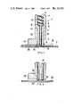
- FIG. 2is a sectional elevation of a second embodiment of welding apparatus according to the invention.
- FIG. 3is a sectional elevation of the delivery tube of a third embodiment according to the invention.
- FIG. 4is a sectional elevation of the shearing surfaces of a fourth embodiment.
- an apparatus 1 for use in the welding of overlapping sheets 2 of thermoplastic material such as polythenecomprises an extruder indicated generally by numeral 3.
- This extruder 3includes a barrel portion 4 which tapers down at its lower end 5 via a conically-shaped shoulder 6 into an elongated delivery tube 7 which is concentric therewith.
- a screw-feeder 8which is adapted to force molten thermoplastic welding material 9 through the delivery tube 7.
- a rotatable member 11Integral with this feeder 8 and at its lower end 10, is a rotatable member 11 of circular cross-section. This rotatable member 11 is concentric with the screw-feeder 8 and extends down the centre of the delivery tube to provide an annular passage 12 for the molten welding material between it and the inner wall of the delivery tube.
- a nozzlewhich enables the molten welding material to escape in a direction substantially transverse to the axis of the delivery tube.
- This nozzleis formed by making the trailing edge 13 of the delivery tube somewhat shorter than the leading edge 14.
- the rotating member 11terminates in a circular smearing surface 15 at a position midway between the leading and trailing edges of the delivery tube.
- the delivery tube 7is encased in an insulating sheath 16 of suitable heat resisting material as for example, that sold under the trade name "Teflon".
- Teflonsuitable heat resisting material as for example, that sold under the trade name "Teflon”.
- the sheath 16extends rearwardly to form a pair of guides 17 which bridge the molten material 28 extruded from the nozzle and support the apparatus on the sheets 2 being welded.
- a preheating device 18for preheating the sheet material prior to welding as is well known in the art.
- thermoplastic materialsuch as polythene for example
- the welding apparatus 1is passed centrally along the overlapping edge of the uppermost sheet.
- the areas of the sheet surfaces immediately adjacent the edgeare preheated to just above the melting point of the thermoplastic material by the heating device 18.
- a layer of molten thermoplastic materialis deposited onto these areas and over the aforementioned edge by the extruder.
- the screw-feeder 8 of the extruder 3forces the molten thermoplastic welding material down through the delivery tube 7. As the material passes down this tube it is constantly mixed by the rotatable member 11 so that there is substantially no temperature gradient between the inner part of the mass of molten material and that part of the material immediately adjacent the delivery tube wall. This ensures that a relatively cool layer of molten material is not deposited immediately onto the sheet material as is the case with known machines.
- the apparatushas a hollow delivery tube 21 which rotates about its axis and terminates in a flat annular smearing surface 23 having projections 24 thereon.
- the rotatable delivery tube 21is encased in an insulating sheath of the same general type as that described in the first embodiment. This sheath however forms both the leading edge of the apparatus as well as the guide 25 at the rear thereof.
- the apparatus of this embodimentis used in the same manner as that of the first embodiment and as it moves along the upper edge of the sheets of material 26 to be welded, molten thermoplastic welding material passes down the tube which in turn rotates about its axis.
- the welding materialis emitted from the delivery tube it passes the smearing surfaces 23 and is thus smeared across the adjacent preheated areas of the sheets which are damaged by the projections 24.
- FIG. 3 of the drawingsA third embodiment is shown in FIG. 3 of the drawings.
- the internal configuration of the delivery tube 29includes means in the form of helical guides 27 which act on the molten material and provide it with a swirling action as it passes therethrough.
- FIG. 4A fourth embodiment of the invention is shown in FIG. 4 and is similar to the first embodiment. Instead of a single shearing surface, two adjacent rotating shearing surfaces 30 and 31 are provided, the one 31 being slightly lower than the other 30. This embodiment is intended to cater for the side action where relatively thick plastics sheets 32 are being welded together.
- each of the surfaces 30 and 31includes projection 33 for damaging the thermoplastic sheets.
- the distance between this surface and surfaces being weldedcould be adjustable so as to either decrease or increase the smearing and shearing action.
- the surfacescould also be on a rotatable member driven independently of the extruder of the apparatus.
Landscapes
- Engineering & Computer Science (AREA)
- Mechanical Engineering (AREA)
- Physics & Mathematics (AREA)
- Thermal Sciences (AREA)
- Lining Or Joining Of Plastics Or The Like (AREA)
- Extrusion Moulding Of Plastics Or The Like (AREA)
- Application Of Or Painting With Fluid Materials (AREA)
- Coating Apparatus (AREA)
- Laminated Bodies (AREA)
Abstract
Description
Claims (21)
Applications Claiming Priority (2)
| Application Number | Priority Date | Filing Date | Title |
|---|---|---|---|
| ZA811667 | 1981-03-13 | ||
| ZA81/1667 | 1981-03-13 |
Related Parent Applications (1)
| Application Number | Title | Priority Date | Filing Date |
|---|---|---|---|
| US06/287,978ReissueUS4377429A (en) | 1981-03-13 | 1981-07-29 | Welding of plastics material |
Publications (1)
| Publication Number | Publication Date |
|---|---|
| USRE32103Etrue USRE32103E (en) | 1986-04-01 |
Family
ID=25575261
Family Applications (2)
| Application Number | Title | Priority Date | Filing Date |
|---|---|---|---|
| US06/287,978CeasedUS4377429A (en) | 1981-03-13 | 1981-07-29 | Welding of plastics material |
| US06/615,378Expired - LifetimeUSRE32103E (en) | 1981-03-13 | 1984-05-30 | Welding of plastics material |
Family Applications Before (1)
| Application Number | Title | Priority Date | Filing Date |
|---|---|---|---|
| US06/287,978CeasedUS4377429A (en) | 1981-03-13 | 1981-07-29 | Welding of plastics material |
Country Status (13)
| Country | Link |
|---|---|
| US (2) | US4377429A (en) |
| JP (1) | JPS57152914A (en) |
| AU (1) | AU545931B2 (en) |
| BR (1) | BR8106107A (en) |
| CA (1) | CA1160144A (en) |
| CH (1) | CH654522A5 (en) |
| DE (1) | DE3132275C2 (en) |
| ES (1) | ES504961A0 (en) |
| FR (1) | FR2501568B1 (en) |
| GB (1) | GB2094708B (en) |
| IL (1) | IL63416A (en) |
| IT (1) | IT1139230B (en) |
| NL (1) | NL190542C (en) |
Cited By (5)
| Publication number | Priority date | Publication date | Assignee | Title |
|---|---|---|---|---|
| US5139853A (en)* | 1991-04-23 | 1992-08-18 | Gundle Lining Construction Corporation | Apparatus and method for lining landfills, reservoirs, hazardous waste disposal sites and the like |
| US5762741A (en)* | 1993-12-21 | 1998-06-09 | E.I. Du Pont De Nemours And Company | Method for bonding polymeric articles |
| US5814175A (en)* | 1995-06-07 | 1998-09-29 | Edlon Inc. | Welded thermoplastic polymer article and a method and apparatus for making same |
| WO2010085624A1 (en) | 2009-01-23 | 2010-07-29 | Amcol International Corporation | Geotechnical applications of improved nanocomposites |
| US20110297316A1 (en)* | 2010-06-04 | 2011-12-08 | Shawcor Ltd. | Low temperature method and system for forming field joints on undersea pipelines |
Families Citing this family (11)
| Publication number | Priority date | Publication date | Assignee | Title |
|---|---|---|---|---|
| ZA811427B (en)* | 1981-03-04 | 1982-03-31 | Gundle Holdings Ltd | Welding of plastics material |
| JPH0520466Y2 (en)* | 1988-02-18 | 1993-05-27 | ||
| CA1323743C (en)* | 1989-01-27 | 1993-11-02 | Franz Purstinger | Dimensionally stable plastics sections |
| JPH03123698A (en)* | 1989-10-06 | 1991-05-27 | Ebara Infilco Co Ltd | Treatment of excretion sewage |
| ATE106036T1 (en)* | 1990-03-23 | 1994-06-15 | Eupen Kabelwerk | METHOD AND DEVICE FOR APPLYING A DETECTOR WIRE TO A CONDUIT. |
| DE9311705U1 (en)* | 1993-08-05 | 1993-10-14 | Wegener Gmbh, 52074 Aachen | Plastic welding machine |
| ITMO20070162A1 (en)* | 2007-05-15 | 2008-11-16 | Pyxis S R L | PROCEDURE FOR THE REALIZATION OF FILTRATION UNITS AND RELATIVE EQUIPMENT |
| DE102010001049A1 (en)* | 2010-01-20 | 2011-07-21 | Greiner Tool.Tec Gmbh | Method and device for producing a composite profile and a composite profile |
| US11389828B2 (en) | 2015-03-24 | 2022-07-19 | Gm Global Technology Operations, Llc | Additive energy director and method of formation |
| DE102023129714A1 (en)* | 2023-10-27 | 2025-04-30 | Fraunhofer-Gesellschaft zur Förderung der angewandten Forschung eingetragener Verein | Automated filling of a gap on a component |
| AT527936B1 (en)* | 2024-07-19 | 2025-08-15 | Royos Joining Solutions Gmbh | Method for joining two components by extruding an additional material |
Citations (6)
| Publication number | Priority date | Publication date | Assignee | Title |
|---|---|---|---|---|
| US2220545A (en)* | 1937-11-20 | 1940-11-05 | Dow Chemical Co | Method of welding thermoplastic materials |
| US2377018A (en)* | 1941-06-27 | 1945-05-29 | Goodrich Co B F | Method of and apparatus for uniting plastic material |
| US2736045A (en)* | 1956-02-28 | kamborian | ||
| US3008862A (en)* | 1956-06-29 | 1961-11-14 | Union Carbide Corp | Extruded bead sealing |
| US4069087A (en)* | 1975-10-04 | 1978-01-17 | Hoechst Aktiengesellschaft | Apparatus for welding articles of thermoplasts |
| US4289552A (en)* | 1977-07-22 | 1981-09-15 | GFA-Gesellschaft fur Flachenabdichtung mit beschrankter Haftung | Method for the continuous welding of thermoplastic sheets |
Family Cites Families (7)
| Publication number | Priority date | Publication date | Assignee | Title |
|---|---|---|---|---|
| DE962745C (en)* | 1953-07-31 | 1957-04-25 | Dynamit Nobel Ag | Device for the continuous production of foils or webs from thermoplastics |
| US3117696A (en)* | 1961-07-12 | 1964-01-14 | Cyril J Herman | Gun for two component adhesives |
| GB1262422A (en)* | 1969-02-06 | 1972-02-02 | Ex Proizv Razrabotke I Izgotov | Device for welding thermoplastic sheet materials |
| DE6945152U (en)* | 1969-11-18 | 1970-02-19 | Hoechst Ag | DEVICE FOR WELDING THERMOPLASTIC OBJECTS |
| LU69549A1 (en)* | 1974-03-04 | 1976-02-04 | ||
| GB1558178A (en)* | 1975-08-04 | 1979-12-19 | Ici Ltd | Method of joining thermoplastic articles |
| US4167914A (en)* | 1977-05-25 | 1979-09-18 | Bolton-Emerson, Inc. | Rotating rod, rotating press roll nip coating apparatus |
- 1981
- 1981-07-21AUAU73158/81Apatent/AU545931B2/ennot_activeCeased
- 1981-07-21GBGB8122382Apatent/GB2094708B/ennot_activeExpired
- 1981-07-24ILIL63416Apatent/IL63416A/enunknown
- 1981-07-29USUS06/287,978patent/US4377429A/ennot_activeCeased
- 1981-08-11CHCH5163/81Apatent/CH654522A5/ennot_activeIP Right Cessation
- 1981-08-14DEDE3132275Apatent/DE3132275C2/ennot_activeExpired
- 1981-08-19FRFR8115940Apatent/FR2501568B1/ennot_activeExpired
- 1981-08-25ESES504961Apatent/ES504961A0/enactiveGranted
- 1981-08-27NLNLAANVRAGE8103987,Apatent/NL190542C/ennot_activeIP Right Cessation
- 1981-09-02JPJP56139226Apatent/JPS57152914A/enactiveGranted
- 1981-09-09CACA000385485Apatent/CA1160144A/ennot_activeExpired
- 1981-09-24BRBR8106107Apatent/BR8106107A/enunknown
- 1981-10-15ITIT24522/81Apatent/IT1139230B/enactive
- 1984
- 1984-05-30USUS06/615,378patent/USRE32103E/ennot_activeExpired - Lifetime
Patent Citations (6)
| Publication number | Priority date | Publication date | Assignee | Title |
|---|---|---|---|---|
| US2736045A (en)* | 1956-02-28 | kamborian | ||
| US2220545A (en)* | 1937-11-20 | 1940-11-05 | Dow Chemical Co | Method of welding thermoplastic materials |
| US2377018A (en)* | 1941-06-27 | 1945-05-29 | Goodrich Co B F | Method of and apparatus for uniting plastic material |
| US3008862A (en)* | 1956-06-29 | 1961-11-14 | Union Carbide Corp | Extruded bead sealing |
| US4069087A (en)* | 1975-10-04 | 1978-01-17 | Hoechst Aktiengesellschaft | Apparatus for welding articles of thermoplasts |
| US4289552A (en)* | 1977-07-22 | 1981-09-15 | GFA-Gesellschaft fur Flachenabdichtung mit beschrankter Haftung | Method for the continuous welding of thermoplastic sheets |
Cited By (7)
| Publication number | Priority date | Publication date | Assignee | Title |
|---|---|---|---|---|
| US5139853A (en)* | 1991-04-23 | 1992-08-18 | Gundle Lining Construction Corporation | Apparatus and method for lining landfills, reservoirs, hazardous waste disposal sites and the like |
| USRE35272E (en) | 1991-04-23 | 1996-06-11 | Gse Lining Technology, Inc. | Apparatus and method for lining landfills, reservoirs, hazardous waste disposal sites and the like |
| US5762741A (en)* | 1993-12-21 | 1998-06-09 | E.I. Du Pont De Nemours And Company | Method for bonding polymeric articles |
| US5814175A (en)* | 1995-06-07 | 1998-09-29 | Edlon Inc. | Welded thermoplastic polymer article and a method and apparatus for making same |
| WO2010085624A1 (en) | 2009-01-23 | 2010-07-29 | Amcol International Corporation | Geotechnical applications of improved nanocomposites |
| US20110297316A1 (en)* | 2010-06-04 | 2011-12-08 | Shawcor Ltd. | Low temperature method and system for forming field joints on undersea pipelines |
| US8857700B2 (en)* | 2010-06-04 | 2014-10-14 | Shawcor Ltd. | Low temperature method for forming field joints on undersea pipelines |
Also Published As
| Publication number | Publication date |
|---|---|
| FR2501568B1 (en) | 1986-09-05 |
| AU7315881A (en) | 1982-09-16 |
| JPS6230829B2 (en) | 1987-07-04 |
| DE3132275C2 (en) | 1986-10-09 |
| NL190542B (en) | 1993-11-16 |
| IT1139230B (en) | 1986-09-24 |
| NL190542C (en) | 1994-04-18 |
| ES8306383A1 (en) | 1983-06-01 |
| IL63416A (en) | 1985-08-30 |
| US4377429A (en) | 1983-03-22 |
| NL8103987A (en) | 1982-10-01 |
| JPS57152914A (en) | 1982-09-21 |
| GB2094708A (en) | 1982-09-22 |
| CA1160144A (en) | 1984-01-10 |
| BR8106107A (en) | 1983-04-12 |
| DE3132275A1 (en) | 1982-09-30 |
| IT8124522A0 (en) | 1981-10-15 |
| ES504961A0 (en) | 1983-06-01 |
| FR2501568A1 (en) | 1982-09-17 |
| GB2094708B (en) | 1984-05-10 |
| AU545931B2 (en) | 1985-08-08 |
| CH654522A5 (en) | 1986-02-28 |
| IL63416A0 (en) | 1981-10-30 |
Similar Documents
| Publication | Publication Date | Title |
|---|---|---|
| USRE32103E (en) | Welding of plastics material | |
| US5134000A (en) | Heat shrinkable protective sheets and methods for their manufacture | |
| US4913772A (en) | Portable thermoplastic welding machine | |
| US5411777A (en) | Heat shrinkable protective sheets | |
| US5039557A (en) | Method for embedding reflective beads in thermoplastic pavement marking lines | |
| JP2000334589A (en) | Method and device for welding | |
| EP0644826B1 (en) | Joining bodies of thermoplastic material | |
| AU6124694A (en) | Method and apparatus for applying a heatable composition | |
| JPH0150588B2 (en) | ||
| US3837961A (en) | Method and apparatus for the closing by transverse welding of flexible tubes made of metal-thermoplastic laminate | |
| US2505647A (en) | Process for welding thermoplastic bodies | |
| US4445955A (en) | Welding of plastics material | |
| CA2022840C (en) | Heat shrinkable protective sheets and methods for their manufacture | |
| FI83489B (en) | FOERFARANDE OCH ANORDNING FOR SAMMANFOGNING AV THERMOPLASTMATERIAL. | |
| FR2502288A1 (en) | PROCESS FOR REVEATING A TUBE AND TUBE OBTAINED | |
| US4575618A (en) | Switch unit for use with heat-recoverable articles | |
| JP2021505452A (en) | Welding equipment | |
| AU650097B2 (en) | Heat shrinkable protective sheets | |
| JP3752279B2 (en) | Method of coating welding rod and cable for cylinder | |
| JPH08230044A (en) | Method and apparatus for welding synthetic resin material | |
| JPH02247911A (en) | Manufacture of lap sheath cable | |
| JPH0671754A (en) | Welding method in head of anchor and electric heating welder | |
| CN1042863A (en) | Welding knife and welding device | |
| JP3552795B2 (en) | Colored cover and mounting method of colored cover | |
| JPH0367018B2 (en) |
Legal Events
| Date | Code | Title | Description |
|---|---|---|---|
| AS | Assignment | Owner name:SAMUSA PLASTICS N.V., 1340 E. RICHEY ROAD, HOUSTON Free format text:ASSIGNMENT OF ASSIGNORS INTEREST.;ASSIGNOR:GUNDLE HOLDINGS (PROPRIETARY) LIMITED;REEL/FRAME:004577/0066 Effective date:19860624 Owner name:GUNDLE LINING SYSTEMS, INC., 1340 E. RICHEY ROAD, Free format text:ASSIGNMENT OF ASSIGNORS INTEREST.;ASSIGNOR:SAMUSA PLASTICS N.V.;REEL/FRAME:004577/0065 Effective date:19860627 | |
| AS | Assignment | Owner name:MBANK DALLAS, NATIONAL ASSOCIATION, A NATIONAL BAN Free format text:SECURITY INTEREST;ASSIGNOR:GUNDLE LINING SYSTEMS, INC., A TX CORP.;REEL/FRAME:004607/0119 Effective date:19860828 Owner name:GUNDLE, GUNDLE LINING CONSTRUCTION CORP., A CORP. Free format text:SECURITY INTEREST;ASSIGNOR:GUNDLE LINING SYSTEMS, INC., A TX CORP.;REEL/FRAME:004607/0119 Effective date:19860828 | |
| FPAY | Fee payment | Year of fee payment:4 | |
| AS | Assignment | Owner name:FIRST REPUBLICBANK HOUSTON, N.A., 700 LOUISIANA ST Free format text:SECURITY INTEREST;ASSIGNOR:GUNDLE LINING SYSTEMS, INC. ("GLS");REEL/FRAME:004848/0967 Effective date:19880315 | |
| FPAY | Fee payment | Year of fee payment:8 | |
| SULP | Surcharge for late payment | ||
| FEPP | Fee payment procedure | Free format text:PAT HOLDER CLAIMS SMALL ENTITY STATUS - SMALL BUSINESS (ORIGINAL EVENT CODE: SM02); ENTITY STATUS OF PATENT OWNER: SMALL ENTITY | |
| FPAY | Fee payment | Year of fee payment:12 | |
| FEPP | Fee payment procedure | Free format text:PAYOR NUMBER ASSIGNED (ORIGINAL EVENT CODE: ASPN); ENTITY STATUS OF PATENT OWNER: SMALL ENTITY | |
| AS | Assignment | Owner name:BANK OF AMERICA, N.A., CALIFORNIA Free format text:SECURITY INTEREST;ASSIGNOR:GSE LINING TECHNOLOGY, INC.;REEL/FRAME:012641/0785 Effective date:20020204 |