USRE31570E - Fluid flowmeter - Google Patents
Fluid flowmeterDownload PDFInfo
- Publication number
- USRE31570E USRE31570EUS06/346,422US34642282AUSRE31570EUS RE31570 EUSRE31570 EUS RE31570EUS 34642282 AUS34642282 AUS 34642282AUS RE31570 EUSRE31570 EUS RE31570E
- Authority
- US
- United States
- Prior art keywords
- flow
- disk
- conduit
- opening
- fluid
- Prior art date
- Legal status (The legal status is an assumption and is not a legal conclusion. Google has not performed a legal analysis and makes no representation as to the accuracy of the status listed.)
- Expired - Lifetime
Links
- 239000012530fluidSubstances0.000titleclaimsabstractdescription69
- 238000010276constructionMethods0.000description4
- 238000011144upstream manufacturingMethods0.000description4
- 239000000356contaminantSubstances0.000description3
- 238000000034methodMethods0.000description3
- 238000005259measurementMethods0.000description2
- 239000002184metalSubstances0.000description2
- 239000002245particleSubstances0.000description2
- 230000007704transitionEffects0.000description2
- 238000003486chemical etchingMethods0.000description1
- 238000004891communicationMethods0.000description1
- 238000013461designMethods0.000description1
- 238000009434installationMethods0.000description1
- 239000007788liquidSubstances0.000description1
- 238000012360testing methodMethods0.000description1
Images

Classifications
- G—PHYSICS
- G01—MEASURING; TESTING
- G01F—MEASURING VOLUME, VOLUME FLOW, MASS FLOW OR LIQUID LEVEL; METERING BY VOLUME
- G01F1/00—Measuring the volume flow or mass flow of fluid or fluent solid material wherein the fluid passes through a meter in a continuous flow
- G01F1/05—Measuring the volume flow or mass flow of fluid or fluent solid material wherein the fluid passes through a meter in a continuous flow by using mechanical effects
- G01F1/34—Measuring the volume flow or mass flow of fluid or fluent solid material wherein the fluid passes through a meter in a continuous flow by using mechanical effects by measuring pressure or differential pressure
- G01F1/36—Measuring the volume flow or mass flow of fluid or fluent solid material wherein the fluid passes through a meter in a continuous flow by using mechanical effects by measuring pressure or differential pressure the pressure or differential pressure being created by the use of flow constriction
- G01F1/40—Details of construction of the flow constriction devices
- G01F1/42—Orifices or nozzles
- G—PHYSICS
- G01—MEASURING; TESTING
- G01F—MEASURING VOLUME, VOLUME FLOW, MASS FLOW OR LIQUID LEVEL; METERING BY VOLUME
- G01F1/00—Measuring the volume flow or mass flow of fluid or fluent solid material wherein the fluid passes through a meter in a continuous flow
- G01F1/05—Measuring the volume flow or mass flow of fluid or fluent solid material wherein the fluid passes through a meter in a continuous flow by using mechanical effects
- G01F1/34—Measuring the volume flow or mass flow of fluid or fluent solid material wherein the fluid passes through a meter in a continuous flow by using mechanical effects by measuring pressure or differential pressure
- G01F1/36—Measuring the volume flow or mass flow of fluid or fluent solid material wherein the fluid passes through a meter in a continuous flow by using mechanical effects by measuring pressure or differential pressure the pressure or differential pressure being created by the use of flow constriction
- G01F1/40—Details of construction of the flow constriction devices
Definitions
- the fields of art to which the invention pertainsinclude the fields of pressure differential measuring and testing devices, flowmeters and conduit restrictors and flow elements.
- the prior arthas developed a variety of linear flowmeters in which a manometer or other device for measuring a pressure differential is connected across opposite sides of a flow restrictor.
- the restrictorcomprises one or more passageways proportioned so that under normal working conditions the resistance to flow through the resistor as a whole is substantially proportional to the rate of flow.
- There are certain levels of inaccuracies inherent in such devices and methodshave been developed to optimize the accuracy of results obtained. See for example Goldsmith U.S. Pat. No. 3,071,001 and Weichbrod U.S. Pat. No. 3,071,160.
- the flow rate of a fluidis measured not by directly determining the pressure differential across a restrictor, but by measuring the actual flow of a small portion of fluid.
- Such applicationsrequire that the flow of the fluid be divided into two or more paths with an exact ratio maintained between the individual path flow rates.
- a very small percentage of the flowis diverted into a measuring section. This percentage may be as small as 1 part in 40,000 and the flow measuring section is typically a very thin tubular conduit which is much longer that its diameter so that laminar flow prevails throughout the conduit.
- the flow rateis directly proportional to pressure drop and inversely proportional to viscosity.
- the present inventionprovides simple and economical methods for assuring laminar flow in both the measuring section and bypass section of a flow splitter so that a constant and predetermined ratio is maintained across the entire range of flow rates to be measured.
- the present constructionovercomes the disadvantages referred to above and additionally provides a wide range of flow, as high as 1,000:1 or higher, obtained with facility and repeatable accuracy. This has been accomplished by using as a flow restrictor one or a juxtaposed plurality of disks, each having one or a plurality of channels formed from its perimeter to an opening through opposite sides of the disk. Fluid is directed to the perimeter of the disk or disks and is conveyed by the conduits to the opening.
- the conduitshave sufficiently large length to diameter ratios (or length to effective hydraulic radius, as defined hereinafter) to assure laminar flow of the fluid.
- the flow restrictorcomprises flat, smooth sided juxtaposed disks, formed with central, aligned openings.
- the central opening in each diskcommunicates via one or more conduits radiating from the central opening to the perimeter of the disk.
- the flow restrictoris combined with an elongate laminar flow conduit, serving as a measuring section, to form a substantially linear flowmeter.
- a substantially linear flowmeterincludes a housing having a fluid inlet and fluid outlet, the housing defining a fluid path between the inlet and outlet.
- the flow restrictoris disposed in this fluid path in parallel circuit with the measuring section conduit.
- Meansare provided for measuring the rate of flow of fluid through the measuring section conduit, which means are known in the prior art and constitute no part of the present invention. The result is a compact structure of simple construction which demonstrates high accuracy in measurements over a substantial range of flow temperature and pressure conditions.
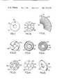
- FIG. 1is a schematic representation of the fluid flow paths in a flow divider
- FIG 2is a schematic illustration in cross-section of portions of a flowmeter incorporating a flow restrictor of this invention
- FIG. 3is an enlarged cross-sectional view of the flow restrictor portion of the flowmeter of FIG. 2;
- FIG. 4is a front elevational view of an exemplary flow restrictor disk used in the flow element of FIG. 3, taken on the line 4--4 of FIG. 3.
- FIG. 5is a cross-sectional view of the flow restrictor disk of FIG. 4, taken on line 5--5 of FIG. 4;
- FIG. 6is a cross-sectional view of the flow restrictor disk of FIG. 4, taken on line 6--6 of FIG. 4;
- FIGS. 7-14are front views of alternative flow restrictor disks.
- FIG. 15is a perspective view of another alternative flow restrictor disk.
- FIGS. 2-6The invention will first be described with respect to a particular type of restrictor or flow element disk as illustrated in FIGS. 2-6. Subsequently, alternative disk configurations will be described as illustrative in FIGS. 7-15. The invention will be described with respect to fluid flowing from left to right in FIGS. 1-3, but the devices described herein are as effective with a reverse fluid flow.
- fluid paths A and Bconstitute the flow through a flowmeter from the inlet at P 1 to the outlet P 2 .
- the line labeled PATH Arepresents fluid flow through the measuring section of the flowmeter and the line designated PATH B represents fluid flow through the bypass section of the flowmeter.
- the pressure dropis the same across each path. It is desired to have the flow rate in PATH A divided by the flow rate in PATH B be a constant at all times.
- PATH Ais a tube of sufficient elongation to assure laminar flow.
- PATH Bmust also assure laminar flow, otherwise the flow ratio would have an undesirable dependency upon temperature and pressure.
- Flow through channelmay be characterized by the nondimensional parameter known as the Reynold's number where
- ⁇is the density of the fluid
- v mis the mean velocity in the conduit
- uis the fluid viscosity
- mis the hydraulic radius defined as the conduit are a divided by the conduit perimeter.
- the effective diameter of the conduitcan be considered to be 4m.
- the Reynold's numberexpresses the ratio of the inertia forces to the viscous forces in the fluid. For low values of R, the flow is laminar, while for high values of R, inertia forces predominate and the flow tends to be turbulent.
- the Reynold's number transitiongenerally occurs in the range of about 1,600 to about 2,800 Reynold's number.
- the transition Reynold's numbercan be determined by noting the mean velocity at which fluid of known density and viscosity flows in a turbulent manner and applying the information to the formula set forth above.
- the following embodimentsillustrate a number of specific structures to accomplish laminar flow in the bypass section, PATH B, in combination with laminar flow in the measuring section, PATH A.
- Each of these embodimentsprovide a flow restrictor in the fluid path through the bypass section, PATH B, defined radially inward (or outward) flow through conduits having length to effective diameter ratios sufficiently large to assure laminar fluid flow.
- the fluid being measuredis gaseous, but the structure and concepts are applicable to liquids as well.
- the flowmeterincludes a housing 12 bored and counterbored to define a passageway 14 formed with inlet and outlet ports 16 and 18, respectively, for the fluid whose flow is to be measured.
- a reduced diameter portion 20defines an annular shoulder 22 for receiving a flow restrictor 24 and an upstream flow directing hollow cylindrical nut 25.
- the flow restrictor 24includes one or a plurality of channeled disks 27 which will be described hereinafter in more detail.
- a passageway region 26is threaded and received the flow restrictor 24 and the matingly threaded cyindrical nut 25.
- the cylindrical nut 25is formed with notches 30 across its far end so as to be readily threaded into the passageway 14 against flow restrictor 24 to secure the flow restrictor 24 in abutment with the shoulder 22.
- An expanded diameter passageway region 32defines a shoulder 34 spaced from the end of the cylindrical nut 25 for receiving a filter screen 36.
- the passageway region 32is threaded and receives a matingly threaded cylindrical securing member 38 for abutment against the filter screen 36, securing the screen 36 in place.
- Upstream and downstream tapsin the form of bore holes 40 and 42, respectively, in the housing, are provided for disposing respective attachment ends 44 and 46 of a measuring section tube 48 on opposite sides of the combination of flow directing nut 25 and flow restrictor 24.
- the attachment ends 44 and 46are tubular members through which the ends of the measuring section tube 48 are tightly secured, so that fluid flowing into the attachment ends 44 and 46 is conducted entirely through the measuring section tube 48.
- the measuring section tubeis very thin and elongate; in this exemplary embodiment the tube 48 has an inside diameter of 0.010 inch and a length of 3.1 inches.
- Thermal elements 50 and 52 on the outside of the tubedetect the mass flow rates of fluid passing through the tube 48. The method by which this is accomplished is known to the art and per se does not constitute a part of this invention.
- the flow restrictor 24consists of a plurality of juxtaposed channeled disks 27 stacked together to create a desired pressure drop and flow rate. This particular illustration incorporates seven disks each with flat parallel surfaces and 0.005 inch in width. There can be as few as 1 disk 27 or as many as 20 or more, depending upon the desired pressure drop and capacity of the housing 12.
- each of the disks 27is formed flat, as a washer, with a central opening 54 through the opposite parallel surfaces.
- four conduits or channels 56are formed through the front surface 58 of the disk radiating from the central opening 54 outwardly to the perimeter 60 of the disk.
- the channels 56serve to conduct fluid from the periphery of the disk 27 to the opening 54.
- each diskshould be flat and its surfaces smooth and free from burrs or unevenness that would interfere with fluid flow in the channels 56 or cause the disks 27 to be separated. Sufficient smoothness can be achieved with chemical etching.
- the diameter of the disk 27is 0.480 inch
- the diameter of the central openingis 0.270 inch
- the length of the channelis 0.105 inch.
- the channel 56is rectangular in cross-section and has height and width dimensions of 0.0025 inch and 0.0085 inch, respectively.
- the cross-sectional area of each channel 56is 0.000021.
- the effective hydraulic radius of the channelcan be calculated as the radius of a circle having an equivalent cross-sectional area; in this case the effective hydraulic radius is 0.0026 inch. Accordingly, each channel has a length to effective hydraulic radius of about 40:1.
- the ratio of length to effective hydraulic radiusshould be at least 4:1 and can be as high as 200:1 or higher.
- the mesh filter 36 located upstream of the flow element 24passes 5 micron particles. In view of the much larger channel diameter, the flow element 24 is protected from clogging from contaminants in the fluid stream.
- the cylindrical nut 25operates in conjunction with the flow restrictor 27 to direct fluid through the conduits 56 radially inwardly to the central opening 54.
- the nut 25is hollow and open at its upstream end 62 and closed at its downstream end by an end wall 64.
- the annular side wall 66 of the nutdefines a plurality of openings 68 adjacent the end wall 64. In this embodiment four such openings are formed, each 0.093 inch in diameter.
- three elongate cylindrical pins 70each threaded at its end are disposed in threaded openings therefor in the downstream surface of the end wall 64. The pins jut from the end wall 64 a distance sufficient to carry the disks 27 for alignment thereof.
- the desired number of disks 27are merely stacked on the pins 70 to define the flow element 24.
- the nut 66is then threaded into the passageway region 26 so that the flow element 24 abuts the shoulder 34 and the nut end wall 64 abuts the flow element 24 and presses the component disks 27 together. No seals are required since the components can be tightly assembled.
- the remainder of the flowmeteris assembled as known to the art and flowmeter electronics are assembled in the housing as known to the prior art, and which are not per se a part of the invention herein.
- fluidis fed into the inlet 16 whereupon it is filtered by the filter screen 36 and travels into the hollow nut 25, through the holes 68 to the perimeters of the stacked disks 27, radially through the conduits 56, to and through the alinged disk openings 54 and emerging from the outlet 18.
- a portion of the fluid streamis diverted through the measuring section tube 48, flowing therethrough to meet the emerging fluid at the outlet 18.
- flow through both the measuring section tube 48 and flow element 24are laminar, yielding accurate measurements over a substantial range of flow, temperature and pressure conditions.
- each disk 27has sufficient thickness to retain dimensional integrity when squeezed by the nut 25. Because of the flatness of the disks 27, the flow meter is not significantly affected by variations in compressive force caused by tightening of the nut 27. Installation of the flow directing components is simple and requires no calibration adjustments for predetermined combinations of disks. Importantly, the present construction permits channels of substantial length allowing substantial cross-section for high length:hydraulic radius ratios. Accordingly, relatively large size particles can pass through the system without plugging the flow restrictor. Furthermore, the entire assembly can be formed of metal, without requiring seals, allowing use of the flow restrictor with otherwise corrosive fluids.
- the particular structure of the disks 27can be varied in number and in configuration to accomodate various flow ranges. Disks having 1-60 or more channels can be used, as well as disks having non-linear channel shapes such as will be described below, in any combination of from 1-40 disks or more to achieve any particular flow range.
- the desired arrangementcan be obtained with simple experimentation or by calculations using the Reynold's number equation given above. Thus, it has been found that a flow range of 5 to 5,000 standard cubic centimeters per minute could be achieved by stacking 1-20 disks comprising one to three differently configurated disks having one, 10 and 50 channels.
- the diameter of the disk opening 54 and the diameter of the disk itselfcan be varied to suit particular needs.
- FIGS. 7-15a variety of disk configurations are shown.
- a disk 77is shown having a central opening 74 and a single channel 76 linearly formed in one surface from the opening 74 to the perimeter of the disk 77.
- a disk 87is shown having a central opening 84 and 10 channels 86 radiating from the opening 84 to the disk perimeter.
- a disk 97is shown having a central opening 94 and 50 radiating channels 96.
- a disk 107is shown having a central opening 104 and four curved channels 106 extending from the opening 104 to the disk perimeter in pinwheel fashion.
- a disk 117is shown having a central opening 114 and a single spirally formed channel 116 connecting the opening 114 to the disk perimeter.
- a disk 127is shown having a central opening 124 and a series of maze-like concentric channels 126 therearound connected by short channels 125 to provide communication between the opening 124 and disk perimeter.
- a disk 137is shown having a central opening 134 and a plurality of circular channels 136 annularly disposed about the opening 134, connected to the opening 134 and disk perimeter by short channels 135.
- a disk 147is shown having a central opening 144 and a plurality of diamond-shaped channels 146 annularly disposed about the opening 144, connected to the opening 144 and disk perimeter by short channels 145.
- a disk 157is shown having a central opening 154 and a plurality of channels 156 in the form of elongate conduits drilled through the body of the disk 157 from the perimeter 159 to the opening 154.
- each of the disks illustrated in FIGS. 7-15can be substituted for one or more disks in the embodiment illustrated in FIG. 3.
- Other variationsare also permissable; for example the opening in each disk can be off-center and means; such as a jig or appropriately spaced alignment pins on the nut 25 can be provided for alignment.
Landscapes
- Physics & Mathematics (AREA)
- Fluid Mechanics (AREA)
- General Physics & Mathematics (AREA)
- Measuring Volume Flow (AREA)
Abstract
Description
R=4mφv.sub.m /u
Claims (10)
Priority Applications (1)
| Application Number | Priority Date | Filing Date | Title |
|---|---|---|---|
| US06/346,422USRE31570E (en) | 1973-04-09 | 1982-02-05 | Fluid flowmeter |
Applications Claiming Priority (2)
| Application Number | Priority Date | Filing Date | Title |
|---|---|---|---|
| US00349169AUS3851526A (en) | 1973-04-09 | 1973-04-09 | Fluid flowmeter |
| US06/346,422USRE31570E (en) | 1973-04-09 | 1982-02-05 | Fluid flowmeter |
Related Parent Applications (1)
| Application Number | Title | Priority Date | Filing Date |
|---|---|---|---|
| US00349169AReissueUS3851526A (en) | 1973-04-09 | 1973-04-09 | Fluid flowmeter |
Publications (1)
| Publication Number | Publication Date |
|---|---|
| USRE31570Etrue USRE31570E (en) | 1984-05-01 |
Family
ID=26994850
Family Applications (1)
| Application Number | Title | Priority Date | Filing Date |
|---|---|---|---|
| US06/346,422Expired - LifetimeUSRE31570E (en) | 1973-04-09 | 1982-02-05 | Fluid flowmeter |
Country Status (1)
| Country | Link |
|---|---|
| US (1) | USRE31570E (en) |
Cited By (21)
| Publication number | Priority date | Publication date | Assignee | Title |
|---|---|---|---|---|
| US4522058A (en) | 1983-06-15 | 1985-06-11 | Mks Instruments, Inc. | Laminar-flow channeling in thermal flowmeters and the like |
| US5253520A (en)* | 1990-12-07 | 1993-10-19 | Dxl International, Inc. | Flow sensor connector |
| US6655207B1 (en)* | 2000-02-16 | 2003-12-02 | Honeywell International Inc. | Flow rate module and integrated flow restrictor |
| US20050179748A1 (en)* | 2002-10-25 | 2005-08-18 | Craig Malik | Techniques for improving pressure sensor shock robustness in fluid containment devices |
| US20060059985A1 (en)* | 2002-11-18 | 2006-03-23 | Yamatake Corporation | Fluid detection device |
| US20070089788A1 (en)* | 2005-07-08 | 2007-04-26 | Chinnock Robert T | Chemically inert flow controller with non-contaminating body |
| US20100300542A1 (en)* | 2009-05-27 | 2010-12-02 | Flowserve Management Company | Fluid flow control devices and systems, and methods of flowing fluids therethrough |
| US20110226053A1 (en)* | 2010-03-22 | 2011-09-22 | Honeywell International Inc. | Flow sensor assembly with porous insert |
| EP2452110A4 (en)* | 2009-05-27 | 2013-04-03 | Flowserve Man Co | DEVICES AND SYSTEMS FOR CONTROLLING FLUID FLOW, AND METHODS FOR FLUID FLOW THROUGH THESE DEVICES AND SYSTEMS |
| US8418549B2 (en) | 2011-01-31 | 2013-04-16 | Honeywell International Inc. | Flow sensor assembly with integral bypass channel |
| US8485031B2 (en) | 2010-03-22 | 2013-07-16 | Honeywell International Inc. | Sensor assembly with hydrophobic filter |
| US8656772B2 (en) | 2010-03-22 | 2014-02-25 | Honeywell International Inc. | Flow sensor with pressure output signal |
| US8695417B2 (en) | 2011-01-31 | 2014-04-15 | Honeywell International Inc. | Flow sensor with enhanced flow range capability |
| US8756990B2 (en) | 2010-04-09 | 2014-06-24 | Honeywell International Inc. | Molded flow restrictor |
| US9003877B2 (en) | 2010-06-15 | 2015-04-14 | Honeywell International Inc. | Flow sensor assembly |
| US9052217B2 (en) | 2012-11-09 | 2015-06-09 | Honeywell International Inc. | Variable scale sensor |
| US20170038237A1 (en)* | 2014-12-05 | 2017-02-09 | General Electric Company | System and method for fluid metering |
| US9952079B2 (en) | 2015-07-15 | 2018-04-24 | Honeywell International Inc. | Flow sensor |
| US20180340643A1 (en)* | 2017-05-25 | 2018-11-29 | Fisher Controls International Llc | Method of Manufacturing a Fluid Pressure Reduction Device |
| US10941878B2 (en) | 2013-03-15 | 2021-03-09 | Flowserve Management Company | Fluid flow control devices and systems, and methods of flowing fluids therethrough |
| US11506305B2 (en) | 2017-05-25 | 2022-11-22 | Fisher Controls International Llc | Method of manufacturing a fluid pressure reduction device |
Citations (40)
| Publication number | Priority date | Publication date | Assignee | Title |
|---|---|---|---|---|
| US76166A (en)* | 1868-03-31 | Joseph cordnan | ||
| US163929A (en)* | 1875-06-01 | Improvement in gas-burners | ||
| US1140548A (en)* | 1914-06-08 | 1915-05-25 | John B Vogelsang | Device for combining and emulsifying substances. |
| US1142674A (en)* | 1915-02-27 | 1915-06-08 | William A Gilchrist | Fuel-atomizer for internal-combustion engines. |
| US1178891A (en)* | 1915-07-08 | 1916-04-11 | Herman Walther | Fuel-mixer. |
| US1559547A (en)* | 1920-03-25 | 1925-11-03 | Francis H Brown | Pressure-responsive device |
| GB251194A (en)* | 1925-11-23 | 1926-04-29 | Wilhelm Schurz | Improvements in or relating to measuring the flow of liquid or gaseous media |
| US1687780A (en)* | 1926-05-01 | 1928-10-16 | Gen Motors Corp | Porous-metal plug for valve lubrication |
| US1701805A (en)* | 1927-02-11 | 1929-02-12 | Irwin L Dunn | Explosion arrester |
| US1814235A (en)* | 1928-12-10 | 1931-07-14 | Wired Radio Inc | Fluid flow indicator |
| US1816390A (en)* | 1926-12-07 | 1931-07-28 | Mobus Wilhelm | Nebulizing and antibackfiring device for internal combustion engines |
| US1870849A (en)* | 1928-06-09 | 1932-08-09 | Hodgson John Lawrence | Flow quantity meter |
| US1883813A (en)* | 1923-10-08 | 1932-10-18 | Morrison Montford | Manometer |
| US2132011A (en)* | 1936-07-17 | 1938-10-04 | Budwig Mfg Company | Beverage dispensing apparatus |
| US2163730A (en)* | 1935-03-29 | 1939-06-27 | Goetzl Manlio | Integrating calorimeter |
| GB520083A (en)* | 1938-10-08 | 1940-04-15 | Kent Ltd G | A device for reducing disturbance in fluid flows |
| US2515394A (en)* | 1946-02-28 | 1950-07-18 | Clarkson Alick | Pressure gauge stabilizer |
| US2604958A (en)* | 1944-09-15 | 1952-07-29 | Karl J G Leufvenius | Lubrication fitting |
| US2661768A (en)* | 1949-10-29 | 1953-12-08 | Standard Oil Dev Co | Indicating orifice plate for threaded orifice union |
| US2687645A (en)* | 1950-03-02 | 1954-08-31 | Askania Regulator Co | Differential pressure flow rate measurement device |
| US2760371A (en)* | 1953-05-29 | 1956-08-28 | B I F Ind Inc | Multiple venturi tube |
| US2815923A (en)* | 1952-07-23 | 1957-12-10 | Gen Electric | Valve with automatic rate-of-flow control |
| US2887129A (en)* | 1956-01-10 | 1959-05-19 | Hughes Aircraft Co | Liquid metering device |
| US2893432A (en)* | 1953-12-31 | 1959-07-07 | Dole Valve Co | Fluid flow control |
| US2927462A (en)* | 1955-10-28 | 1960-03-08 | Yao T Li | Orifice type flowmeter |
| US2929248A (en)* | 1957-11-13 | 1960-03-22 | Bailey Meter Co | Flow meter |
| US3027746A (en)* | 1959-11-16 | 1962-04-03 | Kappel Corp | Flow control device |
| US3071001A (en)* | 1960-02-16 | 1963-01-01 | Nat Instr Lab Inc | Linear flow meter |
| US3071160A (en)* | 1959-07-01 | 1963-01-01 | Nat Instr Lab Inc | Fluid restrictor for linear flow meters |
| US3129587A (en)* | 1960-10-11 | 1964-04-21 | Honeywell Regulator Co | Flow sensing device |
| US3330156A (en)* | 1965-09-08 | 1967-07-11 | Jesse W Thomas | Fluid flowmeters |
| US3349619A (en)* | 1959-07-29 | 1967-10-31 | Meriam Instr Company | Laminar flow element and flow meter |
| US3433068A (en)* | 1964-11-12 | 1969-03-18 | Rosemount Eng Co Ltd | Thermal mass flow sensor |
| US3514074A (en)* | 1968-05-06 | 1970-05-26 | Richard E Self | High energy loss fluid control |
| US3559482A (en)* | 1968-11-27 | 1971-02-02 | Teledyne Inc | Fluid flow measuring apparatus |
| US3613448A (en)* | 1969-11-26 | 1971-10-19 | Teledyne Inc | Fluid flow measuring apparatus |
| US3688800A (en)* | 1970-11-27 | 1972-09-05 | Sanders Associates Inc | Fluid flow restrictor |
| US3722854A (en)* | 1971-12-01 | 1973-03-27 | Grove Valve & Regulator Co | Valve with perforated ribbon silencing element |
| US3792609A (en)* | 1971-05-10 | 1974-02-19 | Tylan Corp | Flow splitter |
| US3805610A (en)* | 1972-06-23 | 1974-04-23 | Emerson Electric Co | Flow dividing means, particularly for thermal flowmeter |
- 1982
- 1982-02-05USUS06/346,422patent/USRE31570E/ennot_activeExpired - Lifetime
Patent Citations (40)
| Publication number | Priority date | Publication date | Assignee | Title |
|---|---|---|---|---|
| US163929A (en)* | 1875-06-01 | Improvement in gas-burners | ||
| US76166A (en)* | 1868-03-31 | Joseph cordnan | ||
| US1140548A (en)* | 1914-06-08 | 1915-05-25 | John B Vogelsang | Device for combining and emulsifying substances. |
| US1142674A (en)* | 1915-02-27 | 1915-06-08 | William A Gilchrist | Fuel-atomizer for internal-combustion engines. |
| US1178891A (en)* | 1915-07-08 | 1916-04-11 | Herman Walther | Fuel-mixer. |
| US1559547A (en)* | 1920-03-25 | 1925-11-03 | Francis H Brown | Pressure-responsive device |
| US1883813A (en)* | 1923-10-08 | 1932-10-18 | Morrison Montford | Manometer |
| GB251194A (en)* | 1925-11-23 | 1926-04-29 | Wilhelm Schurz | Improvements in or relating to measuring the flow of liquid or gaseous media |
| US1687780A (en)* | 1926-05-01 | 1928-10-16 | Gen Motors Corp | Porous-metal plug for valve lubrication |
| US1816390A (en)* | 1926-12-07 | 1931-07-28 | Mobus Wilhelm | Nebulizing and antibackfiring device for internal combustion engines |
| US1701805A (en)* | 1927-02-11 | 1929-02-12 | Irwin L Dunn | Explosion arrester |
| US1870849A (en)* | 1928-06-09 | 1932-08-09 | Hodgson John Lawrence | Flow quantity meter |
| US1814235A (en)* | 1928-12-10 | 1931-07-14 | Wired Radio Inc | Fluid flow indicator |
| US2163730A (en)* | 1935-03-29 | 1939-06-27 | Goetzl Manlio | Integrating calorimeter |
| US2132011A (en)* | 1936-07-17 | 1938-10-04 | Budwig Mfg Company | Beverage dispensing apparatus |
| GB520083A (en)* | 1938-10-08 | 1940-04-15 | Kent Ltd G | A device for reducing disturbance in fluid flows |
| US2604958A (en)* | 1944-09-15 | 1952-07-29 | Karl J G Leufvenius | Lubrication fitting |
| US2515394A (en)* | 1946-02-28 | 1950-07-18 | Clarkson Alick | Pressure gauge stabilizer |
| US2661768A (en)* | 1949-10-29 | 1953-12-08 | Standard Oil Dev Co | Indicating orifice plate for threaded orifice union |
| US2687645A (en)* | 1950-03-02 | 1954-08-31 | Askania Regulator Co | Differential pressure flow rate measurement device |
| US2815923A (en)* | 1952-07-23 | 1957-12-10 | Gen Electric | Valve with automatic rate-of-flow control |
| US2760371A (en)* | 1953-05-29 | 1956-08-28 | B I F Ind Inc | Multiple venturi tube |
| US2893432A (en)* | 1953-12-31 | 1959-07-07 | Dole Valve Co | Fluid flow control |
| US2927462A (en)* | 1955-10-28 | 1960-03-08 | Yao T Li | Orifice type flowmeter |
| US2887129A (en)* | 1956-01-10 | 1959-05-19 | Hughes Aircraft Co | Liquid metering device |
| US2929248A (en)* | 1957-11-13 | 1960-03-22 | Bailey Meter Co | Flow meter |
| US3071160A (en)* | 1959-07-01 | 1963-01-01 | Nat Instr Lab Inc | Fluid restrictor for linear flow meters |
| US3349619A (en)* | 1959-07-29 | 1967-10-31 | Meriam Instr Company | Laminar flow element and flow meter |
| US3027746A (en)* | 1959-11-16 | 1962-04-03 | Kappel Corp | Flow control device |
| US3071001A (en)* | 1960-02-16 | 1963-01-01 | Nat Instr Lab Inc | Linear flow meter |
| US3129587A (en)* | 1960-10-11 | 1964-04-21 | Honeywell Regulator Co | Flow sensing device |
| US3433068A (en)* | 1964-11-12 | 1969-03-18 | Rosemount Eng Co Ltd | Thermal mass flow sensor |
| US3330156A (en)* | 1965-09-08 | 1967-07-11 | Jesse W Thomas | Fluid flowmeters |
| US3514074A (en)* | 1968-05-06 | 1970-05-26 | Richard E Self | High energy loss fluid control |
| US3559482A (en)* | 1968-11-27 | 1971-02-02 | Teledyne Inc | Fluid flow measuring apparatus |
| US3613448A (en)* | 1969-11-26 | 1971-10-19 | Teledyne Inc | Fluid flow measuring apparatus |
| US3688800A (en)* | 1970-11-27 | 1972-09-05 | Sanders Associates Inc | Fluid flow restrictor |
| US3792609A (en)* | 1971-05-10 | 1974-02-19 | Tylan Corp | Flow splitter |
| US3722854A (en)* | 1971-12-01 | 1973-03-27 | Grove Valve & Regulator Co | Valve with perforated ribbon silencing element |
| US3805610A (en)* | 1972-06-23 | 1974-04-23 | Emerson Electric Co | Flow dividing means, particularly for thermal flowmeter |
Cited By (37)
| Publication number | Priority date | Publication date | Assignee | Title |
|---|---|---|---|---|
| US4522058A (en) | 1983-06-15 | 1985-06-11 | Mks Instruments, Inc. | Laminar-flow channeling in thermal flowmeters and the like |
| US5253520A (en)* | 1990-12-07 | 1993-10-19 | Dxl International, Inc. | Flow sensor connector |
| US6655207B1 (en)* | 2000-02-16 | 2003-12-02 | Honeywell International Inc. | Flow rate module and integrated flow restrictor |
| US7654655B2 (en)* | 2002-10-25 | 2010-02-02 | Hewlett-Packard Development Company, L.P. | Labyrinth seal structure |
| US20050179748A1 (en)* | 2002-10-25 | 2005-08-18 | Craig Malik | Techniques for improving pressure sensor shock robustness in fluid containment devices |
| US20060059985A1 (en)* | 2002-11-18 | 2006-03-23 | Yamatake Corporation | Fluid detection device |
| US7228733B2 (en)* | 2002-11-18 | 2007-06-12 | Yamatake Corporation | Fluid detection device |
| CN100376875C (en)* | 2002-11-18 | 2008-03-26 | 株式会社山武 | Fluid detection device |
| US7866337B2 (en)* | 2005-07-08 | 2011-01-11 | Entegris, Inc. | Chemically inert flow controller with non-contaminating body |
| US20070089788A1 (en)* | 2005-07-08 | 2007-04-26 | Chinnock Robert T | Chemically inert flow controller with non-contaminating body |
| US20100300542A1 (en)* | 2009-05-27 | 2010-12-02 | Flowserve Management Company | Fluid flow control devices and systems, and methods of flowing fluids therethrough |
| US9732880B2 (en) | 2009-05-27 | 2017-08-15 | Flowserve Management Company | Fluid flow control devices and systems, and methods of flowing fluids therethrough |
| EP2452110A4 (en)* | 2009-05-27 | 2013-04-03 | Flowserve Man Co | DEVICES AND SYSTEMS FOR CONTROLLING FLUID FLOW, AND METHODS FOR FLUID FLOW THROUGH THESE DEVICES AND SYSTEMS |
| US10989329B2 (en) | 2009-05-27 | 2021-04-27 | Flowserve Management Company | Fluid flow control devices and systems, and methods of flowing fluids therethrough |
| US10550960B2 (en) | 2009-05-27 | 2020-02-04 | Flowserve Management Company | Fluid flow control devices and systems, and methods of flowing fluids therethrough |
| US8881768B2 (en) | 2009-05-27 | 2014-11-11 | Flowserve Management Company | Fluid flow control devices and systems, and methods of flowing fluids therethrough |
| US20110226053A1 (en)* | 2010-03-22 | 2011-09-22 | Honeywell International Inc. | Flow sensor assembly with porous insert |
| US8397586B2 (en) | 2010-03-22 | 2013-03-19 | Honeywell International Inc. | Flow sensor assembly with porous insert |
| US8485031B2 (en) | 2010-03-22 | 2013-07-16 | Honeywell International Inc. | Sensor assembly with hydrophobic filter |
| US8656772B2 (en) | 2010-03-22 | 2014-02-25 | Honeywell International Inc. | Flow sensor with pressure output signal |
| US8756990B2 (en) | 2010-04-09 | 2014-06-24 | Honeywell International Inc. | Molded flow restrictor |
| US9003877B2 (en) | 2010-06-15 | 2015-04-14 | Honeywell International Inc. | Flow sensor assembly |
| US9091577B2 (en) | 2011-01-31 | 2015-07-28 | Honeywell International Inc. | Flow sensor assembly with integral bypass channel |
| US8695417B2 (en) | 2011-01-31 | 2014-04-15 | Honeywell International Inc. | Flow sensor with enhanced flow range capability |
| US8418549B2 (en) | 2011-01-31 | 2013-04-16 | Honeywell International Inc. | Flow sensor assembly with integral bypass channel |
| US9052217B2 (en) | 2012-11-09 | 2015-06-09 | Honeywell International Inc. | Variable scale sensor |
| US11287059B2 (en) | 2013-03-15 | 2022-03-29 | Flowserve Management Company | Fluid flow control devices and systems, and methods of flowing fluids therethrough |
| US11761558B2 (en) | 2013-03-15 | 2023-09-19 | Flowserve Pte. Ltd. | Fluid flow control devices and systems, and methods of flowing fluids therethrough |
| US10941878B2 (en) | 2013-03-15 | 2021-03-09 | Flowserve Management Company | Fluid flow control devices and systems, and methods of flowing fluids therethrough |
| US20170038237A1 (en)* | 2014-12-05 | 2017-02-09 | General Electric Company | System and method for fluid metering |
| US10139259B2 (en)* | 2014-12-05 | 2018-11-27 | General Electric Company | System and method for metering gas based on amplitude and/or temporal characteristics of an electrical signal |
| US9952079B2 (en) | 2015-07-15 | 2018-04-24 | Honeywell International Inc. | Flow sensor |
| US10711937B2 (en)* | 2017-05-25 | 2020-07-14 | Fisher Controls International Llc | Method of manufacturing a fluid pressure reduction device |
| US11506305B2 (en) | 2017-05-25 | 2022-11-22 | Fisher Controls International Llc | Method of manufacturing a fluid pressure reduction device |
| US11719362B2 (en) | 2017-05-25 | 2023-08-08 | Fisher Controls International Llc | Method of manufacturing a fluid pressure reduction device |
| US20180340643A1 (en)* | 2017-05-25 | 2018-11-29 | Fisher Controls International Llc | Method of Manufacturing a Fluid Pressure Reduction Device |
| US12215802B2 (en) | 2017-05-25 | 2025-02-04 | Fisher Controls International Llc | Method of manufacturing a fluid pressure reduction device |
Similar Documents
| Publication | Publication Date | Title |
|---|---|---|
| US3851526A (en) | Fluid flowmeter | |
| USRE31570E (en) | Fluid flowmeter | |
| US5357793A (en) | Fluid metering apparatus | |
| US5511416A (en) | Wide range laminar flow element | |
| US7874208B2 (en) | System for and method of providing a wide-range flow controller | |
| US5576498A (en) | Laminar flow element for a flowmeter | |
| US5295397A (en) | Slotted orifice flowmeter | |
| EP0075343B1 (en) | Laminar flow element | |
| US5804717A (en) | Mass flow transducer having extended flow rate measurement range | |
| DE69711846T2 (en) | BYPASS FLOW METER | |
| US5297427A (en) | Wide-range laminar flowmeter | |
| US5672821A (en) | Laminar flow device | |
| EP0428364A1 (en) | Flowmeter | |
| US5297426A (en) | Hydrodynamic fluid divider for fluid measuring devices | |
| JPS6056219A (en) | Flowmeter | |
| JPH02118205A (en) | Flow stabilizer for fluid, mass flowmeter and mass flow rate controller | |
| EP0350612A3 (en) | Measuring arrangement for establishing pressure and temperature | |
| EP0978020B1 (en) | Proportioner | |
| US4290315A (en) | Apparatus for determining the differential pressure and the volumetric fluid flow in a conduit | |
| JPH037243B2 (en) | ||
| EP1296118B1 (en) | Device to measure gas consumption | |
| KR100760065B1 (en) | Mass Mass Flow Measurement Device | |
| US11624454B2 (en) | Flow resistance insert and a flow rate measuring or flow rate control means | |
| KR102128430B1 (en) | Mass flow meter and bypass flow controlling method for the mass flow meter | |
| JPH0222647Y2 (en) |
Legal Events
| Date | Code | Title | Description |
|---|---|---|---|
| AS | Assignment | Owner name:BANK OF AMERICA NATIONAL TRUST AND SAVINGS ASSOCIA Free format text:SECURITY INTEREST;ASSIGNOR:TYLAN CORPORATION;REEL/FRAME:004702/0182 Effective date:19870403 | |
| AS | Assignment | Owner name:BANK OF AMERICA NATIONAL TRUST AND SAVINGS ASSOCIA Free format text:SECURITY INTEREST;ASSIGNOR:TYLAN CORPORATION;REEL/FRAME:004766/0186 Effective date:19870403 | |
| AS | Assignment | Owner name:SANWA BUSINESS CREDIT CORPORATION, A DE CORP., ILL Free format text:ASSIGNMENT OF ASSIGNORS INTEREST.;ASSIGNOR:TYLAN CORPORATION, A CA CORP.;REEL/FRAME:005161/0619 Effective date:19891005 | |
| AS | Assignment | Owner name:TYLAN GENERAL TCA CORP., CALIFORNIA Free format text:CHANGE OF NAME;ASSIGNOR:TYLAN CORPORATION;REEL/FRAME:006781/0248 Effective date:19900123 | |
| AS | Assignment | Owner name:TYLAN GENERAL, INC., CALIFORNIA Free format text:ASSIGNMENT OF ASSIGNORS INTEREST;ASSIGNOR:TYLAN GENERAL TCA CORP.;REEL/FRAME:006781/0006 Effective date:19931115 | |
| AS | Assignment | Owner name:TYLAN GENERAL, INC., A DELAWARE CORPORATION, CALIF Free format text:MERGER;ASSIGNOR:TYLAN GENERAL, INC., A MASSACHUSETTS CORP.;REEL/FRAME:007888/0638 Effective date:19950127 | |
| AS | Assignment | Owner name:MILLIPORE CORPORATION, A MASSACHUSETTS, MASSACHUSE Free format text:MERGER;ASSIGNOR:TYLAN GENERAL, INC., A DELAWARE CORP.;REEL/FRAME:008783/0969 Effective date:19970731 |