USD1044734S1 - Outdoor electrical device - Google Patents
Outdoor electrical deviceDownload PDFInfo
- Publication number
- USD1044734S1 USD1044734S1US29/809,591US202129809591FUSD1044734SUS D1044734 S1USD1044734 S1US D1044734S1US 202129809591 FUS202129809591 FUS 202129809591FUS D1044734 SUSD1044734 SUS D1044734S
- Authority
- US
- United States
- Prior art keywords
- electrical device
- outdoor electrical
- view
- outdoor
- perspective
- Prior art date
- Legal status (The legal status is an assumption and is not a legal conclusion. Google has not performed a legal analysis and makes no representation as to the accuracy of the status listed.)
- Active
Links
Images


Description
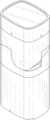
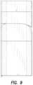
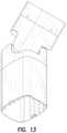
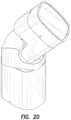
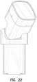
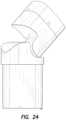
In the drawings, the broken lines are for the purpose of illustrating portions of the outdoor electrical device that form no part of the claimed design.
Claims (1)
- The ornamental design for an outdoor electrical device, as shown and described.
Priority Applications (4)
| Application Number | Priority Date | Filing Date | Title |
|---|---|---|---|
| US29/809,591USD1044734S1 (en) | 2021-09-29 | 2021-09-29 | Outdoor electrical device |
| CA215418FCA215418S (en) | 2021-09-29 | 2022-03-29 | Outdoor lighting device |
| CA215416FCA215416S (en) | 2021-09-29 | 2022-03-29 | Outdoor lighting device |
| CA215417FCA215417S (en) | 2021-09-29 | 2022-03-29 | Outdoor lighting device |
Applications Claiming Priority (1)
| Application Number | Priority Date | Filing Date | Title |
|---|---|---|---|
| US29/809,591USD1044734S1 (en) | 2021-09-29 | 2021-09-29 | Outdoor electrical device |
Publications (1)
| Publication Number | Publication Date |
|---|---|
| USD1044734S1true USD1044734S1 (en) | 2024-10-01 |
Family
ID=87103543
Family Applications (1)
| Application Number | Title | Priority Date | Filing Date |
|---|---|---|---|
| US29/809,591ActiveUSD1044734S1 (en) | 2021-09-29 | 2021-09-29 | Outdoor electrical device |
Country Status (2)
| Country | Link |
|---|---|
| US (1) | USD1044734S1 (en) |
| CA (3) | CA215416S (en) |
Cited By (1)
| Publication number | Priority date | Publication date | Assignee | Title |
|---|---|---|---|---|
| USD1087920S1 (en)* | 2021-09-29 | 2025-08-12 | Hubbell Incorporated | Outdoor power post |
Citations (25)
| Publication number | Priority date | Publication date | Assignee | Title |
|---|---|---|---|---|
| US4543007A (en) | 1983-11-17 | 1985-09-24 | Harvey Hubbell Incorporated | Adjustable luminaire support knuckle |
| USD372018S (en)* | 1995-02-02 | 1996-07-23 | Byrne Norman R | Electrical receptacle lift-up structure |
| USD434001S (en)* | 1999-08-09 | 2000-11-21 | Sayger Jack M | Utility box |
| USD473518S1 (en)* | 2002-03-25 | 2003-04-22 | Tk Canada Limited | Power column |
| US6585221B1 (en)* | 2001-05-17 | 2003-07-01 | Arlington Industries, Inc. | Garden post |
| US6752362B1 (en)* | 2001-05-17 | 2004-06-22 | Arlington Industries, Inc. | Outdoor garden post |
| USD517481S1 (en)* | 2004-05-07 | 2006-03-21 | Vendor Development Group, Inc. | Cylindrical power hub |
| US7163409B1 (en)* | 2006-07-19 | 2007-01-16 | Hoolin Research Company Limited | Modular integrated socket apparatus |
| USD608733S1 (en)* | 2009-05-04 | 2010-01-26 | Portland General Electric Company | Electric vehicle charging station |
| USD608731S1 (en)* | 2008-11-12 | 2010-01-26 | Better Place GmbH | Charge station for an electric vehicle |
| US20100051310A1 (en)* | 2008-08-29 | 2010-03-04 | Wurzer David T | Power post |
| US7886492B2 (en)* | 2004-10-29 | 2011-02-15 | Abl Ip Holding Llc | Pole system |
| USD718241S1 (en)* | 2013-01-09 | 2014-11-25 | Arlington Industries, Inc. | Weatherproof while-in-use free standing garden post receptacle |
| US8915609B1 (en) | 2008-03-20 | 2014-12-23 | Cooper Technologies Company | Systems, methods, and devices for providing a track light and portable light |
| US9048636B2 (en)* | 2011-07-22 | 2015-06-02 | Cast-Perfect Products Inc. | Electrical pedestal |
| USD736016S1 (en)* | 2014-02-12 | 2015-08-11 | Topcon Europe Medical B.V. | Instrument column |
| USD745680S1 (en)* | 2014-02-12 | 2015-12-15 | Topcon Europe Medical B.V. | Instrument column |
| USD792614S1 (en)* | 2015-10-30 | 2017-07-18 | Nz Tube Mills Limited | Post |
| US20170276337A1 (en) | 2016-03-22 | 2017-09-28 | Hubbell Incorporated | Directional accent luminaire with junction box |
| USD799421S1 (en)* | 2016-04-15 | 2017-10-10 | Ecm Peco, Inc. | Electric vehicle charging stand |
| US20180031215A1 (en) | 2015-12-15 | 2018-02-01 | Wangs Alliance Corporation | Led lighting methods and apparatus |
| US20180332204A1 (en) | 2011-11-14 | 2018-11-15 | Tseng-Lu Chien | LED Light Has Built-In Camera-Assembly for Colorful Digital-Data Under Dark Environment |
| US10869401B1 (en)* | 2017-06-15 | 2020-12-15 | Oberon, Inc | Wireless bollard |
| USD922952S1 (en)* | 2018-06-11 | 2021-06-22 | Herman Miller, Inc. | Power supply tower |
| USD947414S1 (en)* | 2020-05-20 | 2022-03-29 | Peak Industries, Inc. | Mobile stackable tower |
- 2021
- 2021-09-29USUS29/809,591patent/USD1044734S1/enactiveActive
- 2022
- 2022-03-29CACA215416Fpatent/CA215416S/enactiveActive
- 2022-03-29CACA215417Fpatent/CA215417S/enactiveActive
- 2022-03-29CACA215418Fpatent/CA215418S/enactiveActive
Patent Citations (26)
| Publication number | Priority date | Publication date | Assignee | Title |
|---|---|---|---|---|
| US4543007A (en) | 1983-11-17 | 1985-09-24 | Harvey Hubbell Incorporated | Adjustable luminaire support knuckle |
| USD372018S (en)* | 1995-02-02 | 1996-07-23 | Byrne Norman R | Electrical receptacle lift-up structure |
| USD434001S (en)* | 1999-08-09 | 2000-11-21 | Sayger Jack M | Utility box |
| US6585221B1 (en)* | 2001-05-17 | 2003-07-01 | Arlington Industries, Inc. | Garden post |
| US6752362B1 (en)* | 2001-05-17 | 2004-06-22 | Arlington Industries, Inc. | Outdoor garden post |
| USD473518S1 (en)* | 2002-03-25 | 2003-04-22 | Tk Canada Limited | Power column |
| USD517481S1 (en)* | 2004-05-07 | 2006-03-21 | Vendor Development Group, Inc. | Cylindrical power hub |
| US7886492B2 (en)* | 2004-10-29 | 2011-02-15 | Abl Ip Holding Llc | Pole system |
| US7163409B1 (en)* | 2006-07-19 | 2007-01-16 | Hoolin Research Company Limited | Modular integrated socket apparatus |
| US8915609B1 (en) | 2008-03-20 | 2014-12-23 | Cooper Technologies Company | Systems, methods, and devices for providing a track light and portable light |
| US20100051310A1 (en)* | 2008-08-29 | 2010-03-04 | Wurzer David T | Power post |
| USD608731S1 (en)* | 2008-11-12 | 2010-01-26 | Better Place GmbH | Charge station for an electric vehicle |
| USD608733S1 (en)* | 2009-05-04 | 2010-01-26 | Portland General Electric Company | Electric vehicle charging station |
| US9048636B2 (en)* | 2011-07-22 | 2015-06-02 | Cast-Perfect Products Inc. | Electrical pedestal |
| US20180332204A1 (en) | 2011-11-14 | 2018-11-15 | Tseng-Lu Chien | LED Light Has Built-In Camera-Assembly for Colorful Digital-Data Under Dark Environment |
| USD718241S1 (en)* | 2013-01-09 | 2014-11-25 | Arlington Industries, Inc. | Weatherproof while-in-use free standing garden post receptacle |
| USD745680S1 (en)* | 2014-02-12 | 2015-12-15 | Topcon Europe Medical B.V. | Instrument column |
| USD736016S1 (en)* | 2014-02-12 | 2015-08-11 | Topcon Europe Medical B.V. | Instrument column |
| USD792614S1 (en)* | 2015-10-30 | 2017-07-18 | Nz Tube Mills Limited | Post |
| US20180031215A1 (en) | 2015-12-15 | 2018-02-01 | Wangs Alliance Corporation | Led lighting methods and apparatus |
| US20170276337A1 (en) | 2016-03-22 | 2017-09-28 | Hubbell Incorporated | Directional accent luminaire with junction box |
| US10415809B2 (en) | 2016-03-22 | 2019-09-17 | Hubbell Incorporated | Directional accent luminaire with junction box |
| USD799421S1 (en)* | 2016-04-15 | 2017-10-10 | Ecm Peco, Inc. | Electric vehicle charging stand |
| US10869401B1 (en)* | 2017-06-15 | 2020-12-15 | Oberon, Inc | Wireless bollard |
| USD922952S1 (en)* | 2018-06-11 | 2021-06-22 | Herman Miller, Inc. | Power supply tower |
| USD947414S1 (en)* | 2020-05-20 | 2022-03-29 | Peak Industries, Inc. | Mobile stackable tower |
Cited By (1)
| Publication number | Priority date | Publication date | Assignee | Title |
|---|---|---|---|---|
| USD1087920S1 (en)* | 2021-09-29 | 2025-08-12 | Hubbell Incorporated | Outdoor power post |
Also Published As
| Publication number | Publication date |
|---|---|
| CA215417S (en) | 2023-07-10 |
| CA215416S (en) | 2023-07-10 |
| CA215418S (en) | 2023-07-10 |
Similar Documents
| Publication | Publication Date | Title |
|---|---|---|
| USD965544S1 (en) | Electronic device | |
| USD1071220S1 (en) | Osteotomy wedge | |
| USD979516S1 (en) | Connector | |
| USD915913S1 (en) | Roof pod housing | |
| USD1055047S1 (en) | Electronic device | |
| USD963602S1 (en) | Mobile electronic device | |
| USD905021S1 (en) | Mount for headphones | |
| USD987649S1 (en) | Support for electric devices | |
| USD994327S1 (en) | Case for electronic device | |
| USD1003901S1 (en) | Stand for portable electronic devices | |
| USD939492S1 (en) | Case for electronic device | |
| USD1001122S1 (en) | Mobile computing device | |
| USD1004102S1 (en) | Oral appliance | |
| USD956987S1 (en) | Electrical stimulation device | |
| USD971813S1 (en) | Rail clamp | |
| USD1026920S1 (en) | Case for electronic device | |
| USD980430S1 (en) | Oral appliance | |
| USD967068S1 (en) | Earphone | |
| USD989002S1 (en) | Electrical appliance | |
| USD974290S1 (en) | Electronic device charger base | |
| USD1027879S1 (en) | Switching device | |
| USD1008980S1 (en) | Protective casing for electrical device | |
| USD994478S1 (en) | Anchor device | |
| USD989003S1 (en) | Electrical appliance | |
| USD1018532S1 (en) | Electronic device |
Legal Events
| Date | Code | Title | Description |
|---|---|---|---|
| FEPP | Fee payment procedure | Free format text:ENTITY STATUS SET TO UNDISCOUNTED (ORIGINAL EVENT CODE: BIG.); ENTITY STATUS OF PATENT OWNER: LARGE ENTITY |