US9999430B2 - Guide sleeve for suprapatellar surgery - Google Patents
Guide sleeve for suprapatellar surgeryDownload PDFInfo
- Publication number
- US9999430B2 US9999430B2US15/391,096US201615391096AUS9999430B2US 9999430 B2US9999430 B2US 9999430B2US 201615391096 AUS201615391096 AUS 201615391096AUS 9999430 B2US9999430 B2US 9999430B2
- Authority
- US
- United States
- Prior art keywords
- sleeve
- grooves
- drill
- tissue protection
- bone nail
- Prior art date
- Legal status (The legal status is an assumption and is not a legal conclusion. Google has not performed a legal analysis and makes no representation as to the accuracy of the status listed.)
- Active
Links
Images


Classifications
- A—HUMAN NECESSITIES
- A61—MEDICAL OR VETERINARY SCIENCE; HYGIENE
- A61B—DIAGNOSIS; SURGERY; IDENTIFICATION
- A61B17/00—Surgical instruments, devices or methods
- A61B17/16—Instruments for performing osteoclasis; Drills or chisels for bones; Trepans
- A61B17/17—Guides or aligning means for drills, mills, pins or wires
- A61B17/1739—Guides or aligning means for drills, mills, pins or wires specially adapted for particular parts of the body
- A61B17/1764—Guides or aligning means for drills, mills, pins or wires specially adapted for particular parts of the body for the knee
- A61B17/1767—Guides or aligning means for drills, mills, pins or wires specially adapted for particular parts of the body for the knee for the patella
- A—HUMAN NECESSITIES
- A61—MEDICAL OR VETERINARY SCIENCE; HYGIENE
- A61B—DIAGNOSIS; SURGERY; IDENTIFICATION
- A61B1/00—Instruments for performing medical examinations of the interior of cavities or tubes of the body by visual or photographical inspection, e.g. endoscopes; Illuminating arrangements therefor
- A61B1/313—Instruments for performing medical examinations of the interior of cavities or tubes of the body by visual or photographical inspection, e.g. endoscopes; Illuminating arrangements therefor for introducing through surgical openings, e.g. laparoscopes
- A61B1/317—Instruments for performing medical examinations of the interior of cavities or tubes of the body by visual or photographical inspection, e.g. endoscopes; Illuminating arrangements therefor for introducing through surgical openings, e.g. laparoscopes for bones or joints, e.g. osteoscopes, arthroscopes
- A—HUMAN NECESSITIES
- A61—MEDICAL OR VETERINARY SCIENCE; HYGIENE
- A61B—DIAGNOSIS; SURGERY; IDENTIFICATION
- A61B1/00—Instruments for performing medical examinations of the interior of cavities or tubes of the body by visual or photographical inspection, e.g. endoscopes; Illuminating arrangements therefor
- A61B1/32—Devices for opening or enlarging the visual field, e.g. of a tube of the body
- A—HUMAN NECESSITIES
- A61—MEDICAL OR VETERINARY SCIENCE; HYGIENE
- A61B—DIAGNOSIS; SURGERY; IDENTIFICATION
- A61B17/00—Surgical instruments, devices or methods
- A61B17/00234—Surgical instruments, devices or methods for minimally invasive surgery
- A—HUMAN NECESSITIES
- A61—MEDICAL OR VETERINARY SCIENCE; HYGIENE
- A61B—DIAGNOSIS; SURGERY; IDENTIFICATION
- A61B17/00—Surgical instruments, devices or methods
- A61B17/16—Instruments for performing osteoclasis; Drills or chisels for bones; Trepans
- A61B17/1613—Component parts
- A61B17/1633—Sleeves, i.e. non-rotating parts surrounding the bit shaft, e.g. the sleeve forming a single unit with the bit shaft
- A—HUMAN NECESSITIES
- A61—MEDICAL OR VETERINARY SCIENCE; HYGIENE
- A61B—DIAGNOSIS; SURGERY; IDENTIFICATION
- A61B17/00—Surgical instruments, devices or methods
- A61B17/16—Instruments for performing osteoclasis; Drills or chisels for bones; Trepans
- A61B17/1662—Instruments for performing osteoclasis; Drills or chisels for bones; Trepans for particular parts of the body
- A61B17/1675—Instruments for performing osteoclasis; Drills or chisels for bones; Trepans for particular parts of the body for the knee
- A61B17/1677—Instruments for performing osteoclasis; Drills or chisels for bones; Trepans for particular parts of the body for the knee for the patella
- A—HUMAN NECESSITIES
- A61—MEDICAL OR VETERINARY SCIENCE; HYGIENE
- A61B—DIAGNOSIS; SURGERY; IDENTIFICATION
- A61B17/00—Surgical instruments, devices or methods
- A61B17/16—Instruments for performing osteoclasis; Drills or chisels for bones; Trepans
- A61B17/1697—Instruments for performing osteoclasis; Drills or chisels for bones; Trepans specially adapted for wire insertion
- A—HUMAN NECESSITIES
- A61—MEDICAL OR VETERINARY SCIENCE; HYGIENE
- A61B—DIAGNOSIS; SURGERY; IDENTIFICATION
- A61B17/00—Surgical instruments, devices or methods
- A61B17/34—Trocars; Puncturing needles
- A—HUMAN NECESSITIES
- A61—MEDICAL OR VETERINARY SCIENCE; HYGIENE
- A61B—DIAGNOSIS; SURGERY; IDENTIFICATION
- A61B17/00—Surgical instruments, devices or methods
- A61B17/34—Trocars; Puncturing needles
- A61B17/3417—Details of tips or shafts, e.g. grooves, expandable, bendable; Multiple coaxial sliding cannulas, e.g. for dilating
- A61B17/3421—Cannulas
- A61B17/3431—Cannulas being collapsible, e.g. made of thin flexible material
- A—HUMAN NECESSITIES
- A61—MEDICAL OR VETERINARY SCIENCE; HYGIENE
- A61B—DIAGNOSIS; SURGERY; IDENTIFICATION
- A61B17/00—Surgical instruments, devices or methods
- A61B17/56—Surgical instruments or methods for treatment of bones or joints; Devices specially adapted therefor
- A—HUMAN NECESSITIES
- A61—MEDICAL OR VETERINARY SCIENCE; HYGIENE
- A61B—DIAGNOSIS; SURGERY; IDENTIFICATION
- A61B17/00—Surgical instruments, devices or methods
- A61B17/56—Surgical instruments or methods for treatment of bones or joints; Devices specially adapted therefor
- A61B17/58—Surgical instruments or methods for treatment of bones or joints; Devices specially adapted therefor for osteosynthesis, e.g. bone plates, screws or setting implements
- A61B17/68—Internal fixation devices, including fasteners and spinal fixators, even if a part thereof projects from the skin
- A61B17/84—Fasteners therefor or fasteners being internal fixation devices
- A61B17/846—Nails or pins, i.e. anchors without movable parts, holding by friction only, with or without structured surface
- A61B17/848—Kirschner wires, i.e. thin, long nails
- A—HUMAN NECESSITIES
- A61—MEDICAL OR VETERINARY SCIENCE; HYGIENE
- A61B—DIAGNOSIS; SURGERY; IDENTIFICATION
- A61B17/00—Surgical instruments, devices or methods
- A61B17/56—Surgical instruments or methods for treatment of bones or joints; Devices specially adapted therefor
- A61B17/58—Surgical instruments or methods for treatment of bones or joints; Devices specially adapted therefor for osteosynthesis, e.g. bone plates, screws or setting implements
- A61B17/88—Osteosynthesis instruments; Methods or means for implanting or extracting internal or external fixation devices
- A61B17/8861—Apparatus for manipulating flexible wires or straps
- A—HUMAN NECESSITIES
- A61—MEDICAL OR VETERINARY SCIENCE; HYGIENE
- A61B—DIAGNOSIS; SURGERY; IDENTIFICATION
- A61B17/00—Surgical instruments, devices or methods
- A61B17/16—Instruments for performing osteoclasis; Drills or chisels for bones; Trepans
- A61B17/1613—Component parts
- A61B17/1615—Drill bits, i.e. rotating tools extending from a handpiece to contact the worked material
- A—HUMAN NECESSITIES
- A61—MEDICAL OR VETERINARY SCIENCE; HYGIENE
- A61B—DIAGNOSIS; SURGERY; IDENTIFICATION
- A61B17/00—Surgical instruments, devices or methods
- A61B17/16—Instruments for performing osteoclasis; Drills or chisels for bones; Trepans
- A61B17/1662—Instruments for performing osteoclasis; Drills or chisels for bones; Trepans for particular parts of the body
- A61B17/1675—Instruments for performing osteoclasis; Drills or chisels for bones; Trepans for particular parts of the body for the knee
- A—HUMAN NECESSITIES
- A61—MEDICAL OR VETERINARY SCIENCE; HYGIENE
- A61B—DIAGNOSIS; SURGERY; IDENTIFICATION
- A61B17/00—Surgical instruments, devices or methods
- A61B2017/00831—Material properties
- A61B2017/00862—Material properties elastic or resilient
- A—HUMAN NECESSITIES
- A61—MEDICAL OR VETERINARY SCIENCE; HYGIENE
- A61B—DIAGNOSIS; SURGERY; IDENTIFICATION
- A61B17/00—Surgical instruments, devices or methods
- A61B17/02—Surgical instruments, devices or methods for holding wounds open, e.g. retractors; Tractors
- A61B17/025—Joint distractors
- A61B2017/0268—Joint distractors for the knee
Definitions
- the present disclosuregenerally relates to surgical instruments for use in surgical procedures.
- a sleeve suitable for suprapatellar surgery and a system comprising the sleeveare described.
- a patient's kneeWhen treating a tibial fracture (e.g., for realigning the tibia), a patient's knee is typically flexed approximately 90° in order for the surgeon to get access to the top of the tibia in front of the patella for inserting an implant such as an intramedullary nail for fracture fixation.
- an implantsuch as an intramedullary nail for fracture fixation.
- patientsreport frequently on high rates of anterior knee pain caused by the common infrapatellar nailing procedure.
- a so-called suprapatellar approach for intramedullary nailing of tibial fracturesmay be used by surgeons, since it provides first evidence of reduced anterior knee pain and thus enhanced clinical outcome.
- a drill sleeveis inserted between the patella and the femur of the patient's knee and the necessary flexion of the knee joint may consequently be significantly less than 90°. Nonetheless, as suprapatellar surgery is performed through a, supposedly, healthy joint (patellofemoral joint), the joint surfaces need to be protected during the surgery.
- DE 10 2008 004 922 A1discloses a device for bone surgery close to a joint of the bone.
- the devicecomprises a sleeve with a central opening and a cylinder with a plurality of canals for insertion of wires.
- the cylinderis adapted to enclose the sleeve.
- a sleevewhich has a longitudinal axis
- the sleevecomprises a first end, a second end, an inner surface, an outer surface and at least two grooves that extend at the inner surface from the first end to the second end, and wherein the grooves are adapted to accommodate elongated fixation elements.
- the elongated fixation elementsmay, for example, be realized as wires (e.g., so-called K-wires), nails or pins.
- the sleevemay function or be used as a guiding sleeve for guiding another component towards a surgical field. It may be used for suprapatellar surgery or other surgical operations.
- the sleevemay be made of a rigid material.
- This rigid materialmay be a metal or a hard plastic material.
- the sleevemay be made of an elastic material.
- the elastic materialmay be advantageous from the perspective of protecting the patella-femoral (or any other) joint.
- a sleeve made of an elastic materialmay permit a wrenching or rotation of the sleeve along the longitudinal axis of the sleeve.
- a sleeve made of an elastic materialmay permit a bending along the longitudinal axis of the sleeve.
- This sleevemay be made from PEEK, ultra-high molecular weight polyethylene, thermoplastic polyurethane (TPU) or combinations thereof.
- the sleevemay have portions along the longitudinal axis where the outer surface adjacent to the at least two grooves projects radially. Such portions have the appearance of ribs.
- the portionsmay extend along more than the half of the length of the sleeve.
- the ribsmay extend along at least two thirds of the length of the sleeve.
- the inner sleeve surfaceis substantially circular along a circumference between the grooves.
- the outer surface along a circumference between the groovesmay also be substantially circular.
- the inner surface and the outer surfacemay be concentric.
- the outer surface adjacent to the groovesmay be circular and concentric with each respective groove.
- the outer surfacemay have ribs along the grooves in the inner surface.
- the sleevemay have a uniform thickness along the entire circumference.
- the thickness between the inner surface and the outer surface along the circumference between the groovesmay be the same as the thickness between the grooves and the outer surface adjacent to the grooves.
- the first end of the sleevemay have a flat surface perpendicular to the longitudinal axis of the sleeve.
- the groovesmay be parallel with the longitudinal axis of the sleeve.
- the groovesmay be inclined relative to the longitudinal axis of the sleeve.
- the angle of the inclination between the grooves and the longitudinal axis of the sleevemay be 20° or less.
- the groovesmay be inclined concentrically towards the second end of the sleeve. The grooves may thus be inclined in such a way that the distance between the grooves in a radial direction is smaller at the second distal end of the sleeve than at the first or proximal end of the sleeve.
- the sleevemay comprise two grooves located substantially at opposite sides along the circumference of the inner surface.
- the two (or more) groovesmay alternatively have an angular distance relative to the longitudinal direction of less than 180°.
- the angular distance between the grooves of the inner surfacemay, for example, be less than 150°.
- the sleevemay comprise three grooves along the circumference of the inner surface.
- the guiding sleevemay comprise four grooves along the circumference of the inner surface. In such a realization, the four grooves may be equally displaced at an angular distance of 90° along the circumference of the inner surface.
- the sleevemay comprise a gripping portion radially and outwardly protruding from the first end of the sleeve.
- the gripping portionmay constitute an end cap of the sleeves.
- the gripping portionmay be asymmetric and protrude only in one direction. Alternatively, the gripping portion may protrude radially in more than one direction.
- the gripping portionmay be provided with a surface structure to provide a better grip.
- the outer surface of the sleevemay have a chamfered portion at the second end.
- the chamfered portionmay be arranged at an angle of approximately 45° in relation to the longitudinal axis of the sleeve.
- the chamfered portionmay extend along the entire circumference of the second end.
- the inner surface of the sleevemay be conical with its larger diameter side proximate to the first end and its smaller diameter side proximate to the second end.
- the inner surfacemay have a conical portion and a cylindrical portion, wherein the larger diameter side of the conical portion is located proximate to the first end, the cylindrical portion extends from the smaller diameter side of the conical portion to the second end and the smaller diameter side of the conical portion has substantially the same diameter as the cylindrical portion.
- the conical portionmay extend in a longitudinal direction of the sleeve along about 25% of the length of the sleeve and the cylindrical portion may extend in a longitudinal direction of the sleeve along about 75% of the length of the sleeve.
- a sleeveconfigured for use in suprapatellar surgery, wherein the sleeve is made of an elastic material.
- a systemcomprising the sleeve as presented herein and a drill sleeve.
- the drill sleevemay be adapted to be inserted into the sleeve.
- An outer surface of the drill sleevemay substantially match the inner surface of the sleeve. Canals for guiding the fixation elements may be defined between the grooves and the outer surface of the drill sleeve.
- the drill sleevemay comprise a portion with an enlarged diameter at a first end of the drill sleeve.
- the portion with an enlarged diametermay comprise at least two openings at an end facing a second end of the drill sleeve.
- the at least two openingsmay be adapted to mate (e.g., align) with the at least two grooves of the sleeve when the drill sleeve is inserted into the sleeve.
- the enlarged diameter portion of the drill sleeve and the outer surface of the first end of the sleevemay be circular and have the same diameter.
- the drill sleevemay or may not have a corresponding gripping portion.
- the at least two openings of the drill sleevemay be inclined relative to the longitudinal axis of the drill sleeve.
- the angle of the inclination between the openings and a longitudinal axis of the drill sleevemay be 20° or less.
- the openingsmay be inclined towards the second end of the drill sleeve.
- the openingsmay be inclined in such a way that the distances between the openings along a circumferential direction are shorter closer to the second end of the drill sleeve than at the first end of the drill sleeve.
- the at least two openingsmay extend from a first end adjacent to a first end of the drill sleeve to the second end of the portion with an enlarged diameter.
- the at least two openingsmay be bores.
- the sleeve and the drill sleevemay be adapted to be rotationally locked relative to each other.
- the sleeve and the drill sleevemay be locked by a protrusion and a recess in the longitudinal direction of the sleeve and the drill sleeve, respectively.
- One or more protrusionsmay be arranged at a flat surface of the first end of the sleeve and one or more corresponding recesses may be arranged at the portion of the drill sleeve having an enlarged diameter, or vice versa.
- the drill sleevemay comprise a recess at the circumference of the portion with an enlarged diameter.
- the recessmay be an opening from the outer surface of the enlarged diameter portion perpendicular to the longitudinal axis of the drill sleeve.
- the end of the openingmay be located outside the inner surface of the drill sleeve.
- the openingmay protrude from the outside of the enlarged diameter portion of the drill sleeve through the inner surface of the drill sleeve.
- the recessmay be a bore.
- the systemmay comprise at least two fixation elements.
- the fixation elementsmay, for example, be wires (such as K-wires), nails or pins.
- the systemmay comprise a device adapted to engage at least one of the sleeve and the drill sleeve for positioning either one or both of them.
- the devicemay comprise a shaft, a handle connected to one end of the shaft and a sleeve holder connected to the opposite end of the shaft.
- the sleeve holdermay define a space in which at least one of the sleeve and the drill sleeve is to be positioned.
- a locking elementmay be movable along the shaft. The locking element may be adapted to protrude into the space of the sleeve holder.
- a control portionmay be connected to the locking element for retracting the locking element out from the space of the sleeve holder.
- the systemmay further comprise a trocar adapted to be inserted into the drill sleeve.
- the trocarmay have a locking element adapted to lock the trocar against (e.g., rotational and/or translational) movement relative to the drill sleeve.
- a method for suprapatellar surgerycomprises providing a system as presented herein, and inserting at least two fixation elements towards the tibia through the at least two grooves of the sleeve, wherein the at least two grooves are closed at their open sides by an outer surface of the drill sleeve.
- FIG. 1shows a perspective view of an embodiment of a sleeve suitable for suprapatellar surgery
- FIG. 2shows a top view of the sleeve of FIG. 1 ;
- FIG. 3shows a bottom view of the sleeve of FIG. 1 ;
- FIG. 4shows a side view of the sleeve of FIG. 1 ;
- FIG. 5shows a cross section of the sleeve along line A-A of FIG. 4 ;
- FIG. 6shows a perspective view of an embodiment of a drill sleeve
- FIG. 7shows a bottom view of the drill sleeve of FIG. 6 ;
- FIG. 8shows a side view of the drill sleeve of FIG. 6 ;
- FIG. 9shows a cross section of a drill sleeve along line B-B of FIG. 8 ;
- FIG. 10shows a perspective view of an embodiment of a trocar
- FIG. 11shows a side view of the trocar of FIG. 10 ;
- FIG. 12shows a side view of an embodiment of a drill
- FIG. 13shows a top view of an embodiment of a device for positioning the drill sleeve
- FIG. 14shows a cross section of the positioning device along line C-C of FIG. 13 , wherein the drill sleeve is connected to the positioning device;
- FIG. 15shows a system embodiment used during suprapatellar surgery
- FIG. 16shows a cross section of a leg at the patella in connection with suprapatellar surgery.
- a sleeve and a system comprising the sleeve suitable for suprapatellar surgerywill be described.
- the same reference numeralswill be used to denote the same or similar structural features of the sleeve and the system with the sleeve. It will be appreciated that the sleeve and the system could also be used for other surgical procedures.
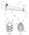
- FIG. 1shows a perspective view of an embodiment of a sleeve 10 .
- the sleeve 10is, in the present embodiment, made from an elastic material so as to protect the tissue or cartilage into which the sleeve is to be introduced.
- the sleeve 10may also be referred to as a guiding sleeve since it is adapted to guide a drill sleeve and fixation elements as described below.
- the sleeve 10has a first or proximal end 12 that will during surgery face away from a tibia and a second or distal end 14 that will be directed towards the tibia.
- the sleeve 10 inner surfacehas two grooves 20 extending from the first end 12 to the second end 14 .
- the two grooves 20are adapted to guide and accommodate elongate fixation elements (not shown) during suprapatellar surgery as will be described in greater detail below.
- An angular distance between the grooves 20 along the circumference of the sleeve 10is approximately 180°.
- the two grooves 20extend substantially parallel with a longitudinal axis of the sleeve 10 at a slight inclination relative to the longitudinal axis such that the radial distance at the first end 12 is larger than at the second end 14 .
- the sleeve 10has an outer surface 18 .
- the outer surface 18has two circular portions 22 along a circumferential direction of the sleeve 10 between the two grooves 20 . Close to the second end 14 , the outer surface 18 adjacent to the grooves 20 extends outside the circular portion 22 , i.e. the outer surface 18 adjacent to the grooves 20 projects radially outwardly in the form of two ribs. Close to the first end 12 , the circular portion 22 of the outer surface 18 extends outside the outer surface 18 adjacent to the grooves 20 .
- the sleeve 10comprises at its first end 12 a gripping portion 28 .
- the gripping portion 28is configured to comprise a radially outwardly protruding tab or flange.
- the gripping portion 28has also a circular section which is concentric relative to the circular portion 22 .
- the gripping portion 28is provided with a plurality of protrusions 44 extending along the longitudinal axis of the sleeve 10 . In the view of FIG. 1 , only two of the protrusions 44 are visible.
- the sleeve 10is provided with a chamfered portion 30 at second end 14 .
- the chamfered portion 30extends along the entire circumference of the second end 14 of the sleeve 10 and facilitates insertion of the sleeve 10 in the patient's joint.
- FIG. 2illustrates a top view of the sleeve 10 as seen from the first end 12 .
- the sleeve 10has an inner surface denoted by 16 .
- the inner surface 16is here illustrated as substantially circular along its circumference between the grooves 20 .
- the gripping portion 28has a flat surface 26 on its top.
- the flat surface 26extends perpendicularly to the longitudinal axis 24 of the sleeve 10 .
- the grooves 20are here illustrated as having a curved bottom with a circumference of approximately 180°. In the view of FIG. 2 , the four proximally extending protrusions 44 can be seen.
- FIG. 3shows a bottom view of the sleeve 10 as seen from the second end 14 .
- the radially outwardly protruding tab of the gripping portion 28is provided with grooves 27 to provide a better grip.
- FIG. 4shows a side view of the sleeve 10 .
- the outer surface 18 between the grooves 20has a conical form with its larger diameter portion close to the gripping portion 28 and its smaller diameter portion close to the chamfered portion 30 .
- Line A-Aextends along the longitudinal axis of the sleeve 10 and is also denoted by 24 .
- Line A-Ais concentric with the inner surface 16 between the grooves 20 .
- FIG. 5shows a cross section along line A-A of FIG. 4 .
- the diameter of the outer surface 18 close to the grooves 20 at the second end 14is larger than the diameter of the outer surface 18 between the grooves 20 at the second end 14 (as illustrated in FIG. 4 ).
- FIG. 6shows a perspective view of a drill sleeve 32 adapted to be inserted into the sleeve 10 .
- the drill sleeve 32has a first or proximal end 34 that during surgery faces away from the tibia and a second end 36 facing towards the tibia.
- the drill sleeve 32has a portion 42 with an enlarged diameter.
- two openings 48 in the form of through-boresare provided.
- One opening 48can be seen in the view of FIG. 6 .
- the drill sleeve 32has a chamfered portion 54 at its second or distal end 36 .
- the drill sleeve 32has an outer surface 40 between the portion 42 with an enlarged diameter and the chamfered portion 54 .
- An inner surface or bore 38 of the drill sleeve 32can be seen through an opening at the second end 36 of the drill sleeve 32 .
- the inner surface 38has a circular cross-section.
- FIG. 7shows a bottom view of the drill sleeve 32 as seen from the second end 36 .
- both openings 48can be seen.
- the openings 48are located at opposite sides relative to a circumference of the inner surface 38 .
- the openings 48have axes that are slightly inclined relative to the longitudinal axis of the drill sleeve 32 .
- the distance between the openings 48 along a circumferential direction at the first end 34is larger than the distance between the openings 48 along a circumferential direction at the distal part of the enlarged diameter portion 42 facing the second end 36 .
- Four recesses 46are arranged along the circumference of the portion 42 .
- the recesses 46are dimensioned to accommodate the protrusions 44 of the sleeve 10 (see FIG. 2 ).
- FIG. 8shows a side view of the drill sleeve 32 .
- a circular recess 56is arranged at the portion 42 having an enlarged diameter.
- the recess 56is here illustrated as a circular opening protruding through the portion 42 into the inner bore 38 .
- the recess 56extends perpendicularly to the longitudinal axis of the drill sleeve 32 .
- the outer surface 40 of the drill sleeve 32has a tubular part 41 and a conical part 43 .
- the conical parthas its larger diameter portion close to the portion 42 i.e., at the proximal end of sleeve 32 , and its smaller diameter part adjacent the tubular part 41 .
- Line B-Bextends along the longitudinal axis of the drill sleeve 32 and is concentric with the inner surface 38 of the drill sleeve 32 .
- Line B-Bis also denoted as 52 .
- the drill sleeve 32has a flat proximal surface 50 extending perpendicularly to longitudinal axis 52 of drill sleeve 32 at first end 34 .
- FIG. 9shows a cross section along line B-B of FIG. 8 .
- the inner surface 38has a tubular part and a conical part.
- the conical parthas its larger diameter side at the first end 34 and its smaller diameter side adjacent to the tubular part.
- the conical parthas a substantially uniform thickness between the chamfered portion 54 and the portion 42 having an enlarged diameter.
- the axes of the openings 48are parallel with the outer surface 40 of the conical part 43 of the drill sleeve 32 .
- FIG. 10shows a perspective view of a trocar 60 for insertion into the drill sleeve 32 .
- the trocar 60has a locking element 62 .
- the locking element 62is flexible in a radial direction of the trocar 60 and has a radially outwardly protruding part.
- the trocar 60is adapted to be locked relative to the drill sleeve 32 by the locking element 62 .
- the trocar 60has a central opening or cannulation along a longitudinal axis of the trocar 60 . This cannulation can be used for a guide wire.
- FIG. 11shows a side view of the trocar 60 .
- the trocar 60has a conical portion at its proximal end facing the femur and a sharp portion at its distal end facing the tibia.
- FIG. 12shows a side view of a drill 64 for insertion into the drill sleeve 32 .
- the drill 64is adapted to be operated at least partly through the drill sleeve 32 when the trocar 60 is removed from the drill sleeve 32 .
- the drill 64may be cannulated to receive a guide wire.
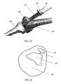
- FIGS. 13 and 14show two views of a device 66 for positioning the drill sleeve 32 .
- the positioning device 66has a shaft 76 , a handle 74 connected to one end of the shaft 76 and a sleeve holder 68 connected to the opposite end of the shaft 76 .
- the sleeve holder 68defines a space in which the drill sleeve 32 is to be inserted.
- a locking element 70is movable along the shaft 76 and adapted to protrude into the space of the sleeve holder 68 .
- a control portion 72is connected to the locking element 70 for retracting the locking element 70 out from the space of the sleeve holder 68 .
- FIG. 14shows a cross section of the positioning device 66 along line C-C of FIG. 13 , wherein the drill sleeve 32 is connected to the positioning device 66 .
- the device 66comprises one magnet 78 connected to the end of the locking element 70 and one magnet 80 connected to the handle 74 .
- the magnets 78 , 80face each other with a pole of the same type, and the locking element 70 is thereby magnetically forced to protrude (or “biased”) into the space of the sleeve holder 68 .
- a coil spring loaded locking element systemcould also be used.
- the front end of the locking element 70engages with the recess 56 of the drill sleeve 32 to inhibit a rotational movement of the drill sleeve 32 relative to the positioning device 66 .
- FIG. 15shows a system comprising the sleeve 10 and the drill sleeve 32 during suprapatellar surgery.
- the drill sleeve 32has been inserted into the sleeve 10 .
- the positioning device 66although not depicted in FIG. 15 , could have been used to position the sleeve 10 and the drill sleeve 32 but might have been detached from the drill sleeve 32 after positioning.
- a patellais denoted by 82
- a femuris denoted by 84
- a tibiais denoted by 86 .
- the sleeve 10is inserted between the patella 82 and the femur 84 and reaches to the top of the tibia 86 (the tibial plateau).
- Two fixation elements 58such as bone pins, are inserted through the openings 48 of the drill sleeve 32 and in the grooves 20 of the sleeve 10 .
- the grooves 20are closed by the outer surface 40 of the drill sleeve 32 to define a closed canal that guides the fixation elements 58 into the tibia.
- the fixation elements 58thus protrude into the tibia 86 for fixation of the system relative to the tibia 86 .
- FIG. 16shows a cross section of a leg at the patella 82 .
- the remainder of the legis denoted as 88 .
- the distance between the patella 82 and the femur 84is indicated by line D.
- the sleeve 10is inserted between the patella 82 and the femur 84 to access the tibia 86 .
- the grooves 20may be arranged more anteriorly along the circumference of the inner surface 16 of the sleeve 10 .
- the angular distance between the grooves 20may be less than 180° (e.g., 120° to 170°) and they may be arranged closer to the patella 82 .
- a surgeonplaces the leg in extension or up to about 15° in flexion.
- the surgeonmay insert the system comprising the trocar 60 , the sleeve 10 and the drill sleeve 32 between the patella 82 and the femur 84 of the patient's leg and incise to the top of the tibia 86 .
- a K-wiremay be inserted through the central opening of the trocar 60 to achieve determination of the correct entry point. Due to the dimensions of the sleeve 10 in the direction D, the patella 82 does not have to be lifted up unnecessarily from the femur 84 .
- the associated jointis protected from being damaged when inserting the system.
- the trocar 60can be inserted into sleeve 10 , a guide wire inserted, the trocar 60 removed and then drill guide sleeve 32 inserted into sleeve 10 followed by drilling.
- fixation elements 58are inserted through the openings 48 of the drill sleeve 32 and in the grooves 20 of the sleeve 10 .
- the openings 48are aligned with the grooves 20 and thus function as aiming devices with respect to the grooves 20 .
- the grooves 20are closed, or covered, at their open ends by the outer surface of the drill sleeve 32 , so that the fixation elements 58 upon insertion through the openings 48 are guided by the resulting laterally closed channels in the sleeve 10 towards the tibia 86 .
- the fixation elements 58are inserted into the tibia 86 for fixation of the system relative to the tibia 86 .
- the trocar 60is removed from the sleeve 10 and a drilling operation can be performed in the tibia 86 through the drill sleeve 32 .
- a tibial implantsuch as an intramedullary nail is inserted into the tibia 86 , and the system and the fixation elements 58 may be removed.
- the provision of at least two grooves at the inner surface of the sleeveenables a thinner overall system structure in the region of a joint to be bypassed during suprapatellar surgery. This results in a minimum incision to the joint surfaces and a minimum risk for injuries of the ligaments and tendons. Furthermore, the grooves at the inner surface of the sleeve facilitate cleaning and sterilization as they are open structures that can easily be accessed by a cleaning or sterilization medium.
Landscapes
- Health & Medical Sciences (AREA)
- Life Sciences & Earth Sciences (AREA)
- Surgery (AREA)
- Orthopedic Medicine & Surgery (AREA)
- Animal Behavior & Ethology (AREA)
- General Health & Medical Sciences (AREA)
- Veterinary Medicine (AREA)
- Engineering & Computer Science (AREA)
- Biomedical Technology (AREA)
- Heart & Thoracic Surgery (AREA)
- Medical Informatics (AREA)
- Molecular Biology (AREA)
- Public Health (AREA)
- Nuclear Medicine, Radiotherapy & Molecular Imaging (AREA)
- Dentistry (AREA)
- Oral & Maxillofacial Surgery (AREA)
- Pathology (AREA)
- Neurology (AREA)
- Physics & Mathematics (AREA)
- Biophysics (AREA)
- Optics & Photonics (AREA)
- Radiology & Medical Imaging (AREA)
- Physical Education & Sports Medicine (AREA)
- Surgical Instruments (AREA)
Abstract
Description
Claims (16)
Priority Applications (2)
| Application Number | Priority Date | Filing Date | Title |
|---|---|---|---|
| US15/391,096US9999430B2 (en) | 2012-01-19 | 2016-12-27 | Guide sleeve for suprapatellar surgery |
| US16/009,858US20180353193A1 (en) | 2012-01-19 | 2018-06-15 | Guide Sleeve For Suprapatellar Surgery |
Applications Claiming Priority (5)
| Application Number | Priority Date | Filing Date | Title |
|---|---|---|---|
| EP12000339.7 | 2012-01-19 | ||
| EP12000339.7AEP2617370B1 (en) | 2012-01-19 | 2012-01-19 | Sleeve in particular for suprapatellar surgery |
| EP12000339 | 2012-01-19 | ||
| US13/743,925US9566078B2 (en) | 2012-01-19 | 2013-01-17 | Guide sleeve for suprapatellar surgery |
| US15/391,096US9999430B2 (en) | 2012-01-19 | 2016-12-27 | Guide sleeve for suprapatellar surgery |
Related Parent Applications (1)
| Application Number | Title | Priority Date | Filing Date |
|---|---|---|---|
| US13/743,925ContinuationUS9566078B2 (en) | 2012-01-19 | 2013-01-17 | Guide sleeve for suprapatellar surgery |
Related Child Applications (1)
| Application Number | Title | Priority Date | Filing Date |
|---|---|---|---|
| US16/009,858ContinuationUS20180353193A1 (en) | 2012-01-19 | 2018-06-15 | Guide Sleeve For Suprapatellar Surgery |
Publications (2)
| Publication Number | Publication Date |
|---|---|
| US20170105741A1 US20170105741A1 (en) | 2017-04-20 |
| US9999430B2true US9999430B2 (en) | 2018-06-19 |
Family
ID=45531748
Family Applications (3)
| Application Number | Title | Priority Date | Filing Date |
|---|---|---|---|
| US13/743,925Active2033-04-21US9566078B2 (en) | 2012-01-19 | 2013-01-17 | Guide sleeve for suprapatellar surgery |
| US15/391,096ActiveUS9999430B2 (en) | 2012-01-19 | 2016-12-27 | Guide sleeve for suprapatellar surgery |
| US16/009,858AbandonedUS20180353193A1 (en) | 2012-01-19 | 2018-06-15 | Guide Sleeve For Suprapatellar Surgery |
Family Applications Before (1)
| Application Number | Title | Priority Date | Filing Date |
|---|---|---|---|
| US13/743,925Active2033-04-21US9566078B2 (en) | 2012-01-19 | 2013-01-17 | Guide sleeve for suprapatellar surgery |
Family Applications After (1)
| Application Number | Title | Priority Date | Filing Date |
|---|---|---|---|
| US16/009,858AbandonedUS20180353193A1 (en) | 2012-01-19 | 2018-06-15 | Guide Sleeve For Suprapatellar Surgery |
Country Status (3)
| Country | Link |
|---|---|
| US (3) | US9566078B2 (en) |
| EP (1) | EP2617370B1 (en) |
| ES (1) | ES2656974T3 (en) |
Cited By (6)
| Publication number | Priority date | Publication date | Assignee | Title |
|---|---|---|---|---|
| US20180353193A1 (en)* | 2012-01-19 | 2018-12-13 | Stryker European Holdings I, Llc | Guide Sleeve For Suprapatellar Surgery |
| US11246566B2 (en)* | 2015-06-26 | 2022-02-15 | B-K Medical Aps | US imaging probe with an instrument channel |
| USD966505S1 (en)* | 2020-07-01 | 2022-10-11 | Nico Corporation | Outer sheath |
| US11918235B1 (en)* | 2020-09-03 | 2024-03-05 | Smith & Nephew, Inc. | Tissue protection sleeve |
| USD1086449S1 (en)* | 2015-03-25 | 2025-07-29 | Orthocision Inc. | Surgical cannula |
| USD1088224S1 (en) | 2013-03-15 | 2025-08-12 | Orthocision Inc. | Surgical cannula |
Families Citing this family (22)
| Publication number | Priority date | Publication date | Assignee | Title |
|---|---|---|---|---|
| EP2797521B1 (en)* | 2011-12-29 | 2015-12-09 | Synthes GmbH | Suprapatellar insertion system |
| US9138278B2 (en)* | 2012-05-04 | 2015-09-22 | Zimmer, Inc. | Suprapatellar system and method |
| EP3158952B1 (en)* | 2012-09-14 | 2019-10-23 | Synthes GmbH | Multihole drill sleeve with protection sleeve |
| DE102012223691A1 (en)* | 2012-12-19 | 2014-06-26 | Heine Optotechnik Gmbh & Co Kg | Otoscope with disposable ear funnel |
| EP2961337B1 (en)* | 2013-02-28 | 2021-04-28 | Feibel, Jonathan | Systems and apparatuses for reaming bone elements |
| US10105161B2 (en) | 2014-08-15 | 2018-10-23 | Covidien Lp | Obturator having an insufflation pathway and an instrument guide |
| EP3232956B1 (en)* | 2014-12-11 | 2019-02-20 | Sudhir Srivastava | Minimally invasive surgical cannula |
| US11083503B2 (en) | 2016-09-22 | 2021-08-10 | Globus Medical, Inc. | Systems and methods for intramedullary nail implantation |
| US10299847B2 (en) | 2016-09-22 | 2019-05-28 | Globus Medical, Inc. | Systems and methods for intramedullary nail implantation |
| US10751096B2 (en) | 2016-09-22 | 2020-08-25 | Bala Sundararajan | Systems and methods for intramedullary nail implantation |
| US10492803B2 (en) | 2016-09-22 | 2019-12-03 | Globus Medical, Inc. | Systems and methods for intramedullary nail implantation |
| US11045242B2 (en) | 2016-09-22 | 2021-06-29 | Globus Medical, Inc. | Systems and methods for intramedullary nail implantation |
| US10603054B2 (en)* | 2017-10-31 | 2020-03-31 | Sicage Llc | Parallel guide for surgical implants |
| US11452517B2 (en)* | 2018-06-04 | 2022-09-27 | West Gen Technologies, L.L.C. | Fixation device cartridges |
| CN109009403B (en)* | 2018-09-11 | 2023-12-19 | 苏州中科生物医用材料有限公司 | Intramedullary nail sleeve device for patellar access tibia |
| USD907772S1 (en) | 2019-06-03 | 2021-01-12 | West Gen Technologies, L.L.C. | Fixation device cartridge |
| USD907773S1 (en) | 2019-06-03 | 2021-01-12 | West Gen Technologies, L.L.C. | Fixation device cartridge |
| USD929586S1 (en) | 2019-06-03 | 2021-08-31 | West Gen Technologies, L.L.C. | Guide tool |
| US11633219B2 (en) | 2019-06-26 | 2023-04-25 | Globus Medical, Inc. | Fenestrated pedicle nail |
| US11490942B2 (en)* | 2019-11-05 | 2022-11-08 | DePuy Synthes Products, Inc. | Device and system for facilitating insertion of a bone treatment device |
| AU2021281513A1 (en)* | 2020-05-28 | 2023-02-02 | Orthoxel Dac | A tibial suprapatellar entry portal system |
| US11478260B2 (en) | 2020-07-17 | 2022-10-25 | Asfora Ip, Llc | Parallel guide for access needle |
Citations (142)
| Publication number | Priority date | Publication date | Assignee | Title |
|---|---|---|---|---|
| US2181746A (en) | 1939-02-04 | 1939-11-28 | John R Siebrandt | Combination bone clamp and adjustable drill guide |
| US2969162A (en) | 1957-04-22 | 1961-01-24 | Kimble Glass Co | Molded picture tube |
| CH396304A (en) | 1962-11-17 | 1965-07-31 | Hernan Dr Med Gasser | Gauge for screwing in bone screws |
| US3867932A (en) | 1974-01-18 | 1975-02-25 | Donald R Huene | Assembly for inserting rigid shafts into fractured bones |
| US4237875A (en) | 1979-02-23 | 1980-12-09 | Towmotor Corporation | Dynamic intramedullary compression nailing |
| US4441492A (en) | 1982-09-29 | 1984-04-10 | Nils Rydell | Aid for telescopic nail for orthopedic use |
| US4449532A (en) | 1980-07-08 | 1984-05-22 | Karl Storz | Dilator to facilitate endoscope insertion into the body |
| US4498468A (en) | 1981-05-11 | 1985-02-12 | Hansson Lars Ingvar | Bone fixation driving instrument |
| US4545374A (en)* | 1982-09-03 | 1985-10-08 | Jacobson Robert E | Method and instruments for performing a percutaneous lumbar diskectomy |
| US4549538A (en) | 1982-11-12 | 1985-10-29 | Zimmer, Inc. | Pin inserter sheath |
| US4616638A (en) | 1982-01-18 | 1986-10-14 | Richards Medical Company | Compression screw assembly |
| US4621628A (en) | 1983-09-09 | 1986-11-11 | Ortopedia Gmbh | Apparatus for locating transverse holes of intramedullary implantates |
| US4699611A (en) | 1985-04-19 | 1987-10-13 | C. R. Bard, Inc. | Biliary stent introducer |
| EP0273872A1 (en) | 1986-12-02 | 1988-07-06 | G. CREMASCOLI S.p.A. | An intramedullary nail and apparatus for its insertion |
| CH668692A5 (en) | 1984-11-30 | 1989-01-31 | Synthes Ag | Bone pin alignment instrument - has lockable head pivoting in all directions |
| US4872451A (en) | 1987-02-02 | 1989-10-10 | Moore Robert R | Glenohumeral ligament repair |
| EP0361641A1 (en) | 1988-09-28 | 1990-04-04 | Fernando Colchero Rozas | Guiding instrument for piercing the cortical bone, suitable for the location of the holes for intra marrow pins |
| US4917111A (en) | 1987-10-15 | 1990-04-17 | Dietmar Pennig | Instrument for aiming and hole forming for implantation of locking nails of the like |
| US4959538A (en) | 1988-04-05 | 1990-09-25 | Heuft-Qualiplus B.V. | Inspection device |
| US4969889A (en) | 1986-12-22 | 1990-11-13 | Zimmer, Inc. | Instrument for locating a hole |
| US5147367A (en) | 1991-02-22 | 1992-09-15 | Ellis Alfred B | Drill pin guide and method for orthopedic surgery |
| US5160323A (en) | 1989-05-26 | 1992-11-03 | Andrew Daniel E | Method and system for inserting spinal catheters |
| EP0518071A1 (en) | 1991-06-13 | 1992-12-16 | Howmedica GmbH | Device for making holes for the implantation of interlocking nails |
| US5207753A (en)* | 1991-02-18 | 1993-05-04 | Kannivelu Badrinath | Bone fracture repair apparatus and method |
| EP0550814A2 (en) | 1991-12-07 | 1993-07-14 | Howmedica GmbH | Anchorage nail for the treatment of hollow bone fractures |
| US5324295A (en)* | 1992-04-24 | 1994-06-28 | Shapiro Michael R | Drill guide for surgical pins |
| EP0623006A1 (en) | 1992-01-24 | 1994-11-09 | Biocon Oy | Surgical installation instrument |
| EP0633748A1 (en) | 1991-12-03 | 1995-01-18 | Boston Scientific Ireland Limited | Bone Anchor Implantation Device |
| US5429641A (en) | 1993-03-28 | 1995-07-04 | Gotfried; Yechiel | Surgical device for connection of fractured bones |
| US5431676A (en) | 1993-03-05 | 1995-07-11 | Innerdyne Medical, Inc. | Trocar system having expandable port |
| EP0712607A2 (en) | 1988-06-13 | 1996-05-22 | MICHELSON, Gary Karlin | Apparatus for use in spinal surgery |
| US5601550A (en) | 1994-10-25 | 1997-02-11 | Esser; Rene D. | Pelvic pin guide system for insertion of pins into iliac bone |
| US5624447A (en) | 1995-03-20 | 1997-04-29 | Othy, Inc. | Surgical tool guide and entry hole positioner |
| US5681320A (en)* | 1991-12-13 | 1997-10-28 | Mcguire; David A. | Bone-cutting guide |
| US5683400A (en)* | 1991-12-13 | 1997-11-04 | Mcguire; David A. | Graft preparation table |
| US5766221A (en)* | 1991-12-03 | 1998-06-16 | Boston Scientific Technology, Inc. | Bone anchor implantation device |
| US5779705A (en) | 1994-06-10 | 1998-07-14 | Matthews; Michael Gordon | Intramedullary nail |
| US5800409A (en)* | 1993-01-12 | 1998-09-01 | Arthroscopic Assistants, Inc. | Flexible inflow/outflow cannula |
| DE19708279A1 (en) | 1997-02-28 | 1998-09-10 | Baumgart Rainer | Distraction system for tubular bone, with marker nail |
| EP0882431A1 (en) | 1997-06-05 | 1998-12-09 | Claudio Di Bartolomei | Device for the elastic intramedullary synthesis of bone fractures |
| US5951561A (en)* | 1998-06-30 | 1999-09-14 | Smith & Nephew, Inc. | Minimally invasive intramedullary nail insertion instruments and method |
| US6010505A (en) | 1996-09-05 | 2000-01-04 | Howmedica Gmbh | Supra condylus bone nail |
| US6033407A (en)* | 1998-01-27 | 2000-03-07 | Behrens; Alfred F. | Apparatus and method for intramedullary nailing and intramedullary nail therefor |
| US6063088A (en)* | 1997-03-24 | 2000-05-16 | United States Surgical Corporation | Method and instrumentation for implant insertion |
| RU2152188C1 (en) | 1999-07-14 | 2000-07-10 | Кемеровская городская клиническая больница N 3 им. М.А. Подгорбунского | Method and device for performing osteosynthesis in the cases of medial fractures of femur neck |
| US6120511A (en) | 1997-11-18 | 2000-09-19 | Chan; Kwan-Ho | Drill guide assembly and method for producing a bone tunnel |
| US6120504A (en) | 1998-12-10 | 2000-09-19 | Biomet Inc. | Intramedullary nail having dual distal bore formation |
| US6206880B1 (en) | 2000-02-21 | 2001-03-27 | Abbas Karladani | Method for percutaneous intramedullary nailing of tibial shaft fractures |
| US6228022B1 (en)* | 1998-10-28 | 2001-05-08 | Sdgi Holdings, Inc. | Methods and instruments for spinal surgery |
| US6270499B1 (en) | 1997-10-20 | 2001-08-07 | Synthes (U.S.A.) | Bone fixation device |
| EP1124492A1 (en) | 1998-11-02 | 2001-08-22 | Grampian Healthcare National Health Service Trust | Fracture treatment |
| US6402753B1 (en) | 1999-06-10 | 2002-06-11 | Orthodyne, Inc. | Femoral intramedullary rod system |
| WO2002067811A2 (en) | 2001-01-16 | 2002-09-06 | Hyde Edward R Jr | Prostheses and instrumentation for joint replacement and repair |
| US20020133156A1 (en) | 1999-06-10 | 2002-09-19 | Cole J. Dean | Femoral intramedullary rod system |
| US20030004513A1 (en)* | 2001-06-27 | 2003-01-02 | Guzman Pamela C. | Method and apparatus for use in the performance of endoscopic minimally invasive orthopaedic plating procedures |
| US20030018340A1 (en)* | 2001-06-29 | 2003-01-23 | Branch Thomas P. | Method and apparatus for installing cannula |
| EP1285630A1 (en) | 2001-08-16 | 2003-02-26 | Waldemar Link (GmbH & Co.) | Surgical instrument set |
| WO2003015650A1 (en) | 2001-08-21 | 2003-02-27 | Depuy Products, Inc. | Method and apparatus for percutaneously securing a bone screw and a bone plate to a bone of a patient |
| DE10309987A1 (en) | 2003-02-28 | 2004-09-16 | Aesculap Ag & Co. Kg | Surgical positioning and holding device |
| US20040243138A1 (en) | 2003-03-14 | 2004-12-02 | Cole J. Dean | Percutaneous fixator and method of insertion |
| EP1488746A1 (en) | 2003-06-20 | 2004-12-22 | Stryker Trauma GmbH | Device for correctly inserting a guide wire for a drill in a bone |
| US20040267276A1 (en)* | 2003-06-30 | 2004-12-30 | Camino Thomas S. | Slide and kit for delivering implants |
| US20050004577A1 (en)* | 2002-01-09 | 2005-01-06 | Dankward Hontzsch | Device for drilling or for inserting implants |
| US20050137605A1 (en)* | 2003-10-23 | 2005-06-23 | Assell Robert L. | Guide pin for guiding instrumentation along a soft tissue tract to a point on the spine |
| US20050261698A1 (en)* | 2004-05-19 | 2005-11-24 | Sean Powell | Snap-lock for drill sleeve |
| WO2006040508A1 (en) | 2004-10-13 | 2006-04-20 | Biocomposites Limited | Trocar with obturator having longitudinal through holes for guiding wires |
| US20060155290A1 (en)* | 2003-07-11 | 2006-07-13 | Konsei Shino | Instrument for reconstructing ligament and method of reconstructing ligament |
| US7090677B2 (en) | 2002-02-12 | 2006-08-15 | Medicine Lodge, Inc. | Surgical milling instrument for shaping a bone cavity |
| US20060229730A1 (en)* | 2005-03-14 | 2006-10-12 | Topez Orthopedics, Inc. | Ankle replacement system |
| US20070100342A1 (en) | 2005-10-14 | 2007-05-03 | Green Daniel W | System for intramedullary rod fixation and method therefor |
| US7217246B1 (en)* | 2004-06-17 | 2007-05-15 | Biomet Sports Medicine, Inc. | Method and apparatus for retaining a fixation pin to a cannula |
| US20070118119A1 (en)* | 2005-11-18 | 2007-05-24 | Zimmer Spine, Inc. | Methods and device for dynamic stabilization |
| US20070225568A1 (en)* | 2006-03-22 | 2007-09-27 | Dennis Colleran | Surgical retractor device and method of use |
| US20070255282A1 (en)* | 2006-04-27 | 2007-11-01 | Sdgi Holdings, Inc. | Dilating stylet and cannula |
| US20080103506A1 (en)* | 2006-10-30 | 2008-05-01 | Depuy Mitek, Inc. | Methods and devices for ligament repair |
| US20080132900A1 (en)* | 2006-11-13 | 2008-06-05 | Stryker Trauma Gmbh | Drill alignment assembly for a bone plate using tissue protection sleeves that are fixed in the bone plate |
| US20080183171A1 (en) | 2007-01-26 | 2008-07-31 | Ebi, L.P. | Lockable intermedullary fixation device |
| US20080208261A1 (en) | 2006-01-13 | 2008-08-28 | Medoff Robert J | Method of using an intramedullary implant for fracture fixation |
| US20080221394A1 (en)* | 2007-03-08 | 2008-09-11 | Warsaw Orthopedic, Inc. | Tissue retractor |
| US20080269749A1 (en) | 2007-04-24 | 2008-10-30 | Osteolign | Thermo-Chemically Activated Implantable Apparatus and Method |
| US20080269751A1 (en) | 2007-01-11 | 2008-10-30 | Anthem Orthopaedics Llc | Percutaneous intramedullary bone repair device and method for using same |
| US20080287950A1 (en) | 2005-11-08 | 2008-11-20 | Robert Frigg | Intramedullary, Longitudinal Implant |
| US20080294172A1 (en)* | 2007-05-23 | 2008-11-27 | Rainer Baumgart | Instrument set for minimally invasive preparation for bone nailing |
| US20080294164A1 (en) | 2007-01-26 | 2008-11-27 | Ebi, Llc. | Lockable intramedullary fixation device |
| US20090036746A1 (en)* | 2007-08-01 | 2009-02-05 | Jonathan Blackwell | Instrumentation for tissue retraction |
| US20090043310A1 (en) | 2005-02-08 | 2009-02-12 | Rasmussen G Lynn | Arthroplasty systems and methods for optimally aligning and tensioning a knee prosthesis |
| US20090043309A1 (en) | 2005-02-08 | 2009-02-12 | Rasmussen G Lynn | Systems and methods for guiding cuts to a femur and tibia during a knee arthroplasty |
| US20090088761A1 (en)* | 2007-09-30 | 2009-04-02 | Roose Jeffrey R | Patient-Customizable Device and System for Performing an Orthopaedic Surgical Procedure |
| US20090138044A1 (en)* | 2007-11-28 | 2009-05-28 | Bergeron Brian J | Stabilization system and method |
| DE102008004922A1 (en) | 2008-01-18 | 2009-07-30 | Arthur Nudelman | Hollow space producing device for receiving implants that connects bones e.g. pelvic bones, of ankle joints, has strands engage behind guidance on side turned away from bones under form-fit connection of guidance with bones |
| US20090299372A1 (en)* | 2008-06-02 | 2009-12-03 | Steiner Anton J | Surgical allograft bone plug cutting tool assembly and method of using same |
| US20100022844A1 (en)* | 2005-06-22 | 2010-01-28 | Mangiardi John R | Surgical Access Instruments for Use with Spinal or Orthopedic Surgery |
| US20100042104A1 (en)* | 2008-04-15 | 2010-02-18 | Sridhar Kota | Surgical tools and components thereof |
| US20100063507A1 (en)* | 2007-02-09 | 2010-03-11 | Sidebotham Christopher G | Low cost modular tapered and spherical hollow reamers for medical applications |
| US20100121339A1 (en)* | 2001-03-13 | 2010-05-13 | Depuy Mitek, Inc. | Method and apparatus for fixing a graft in a bone tunnel |
| US7762949B2 (en)* | 2003-10-16 | 2010-07-27 | Granit Medical Innovation, Llc | Endoscope with open channels |
| US20100191245A1 (en)* | 2003-02-24 | 2010-07-29 | Arthrosurface Incorporated | Trochlear Resurfacing System and Method |
| US20100222782A1 (en)* | 2009-02-27 | 2010-09-02 | Howmedica Osteonics Corp. | Spot facing trochlear groove |
| US20100228253A1 (en)* | 2009-02-05 | 2010-09-09 | Plecko Michael | Reamer and Drill Guiding Device |
| US20100241121A1 (en)* | 2007-05-14 | 2010-09-23 | Howmedica Osteonics Corp. | Flexible intramedullary rod |
| US20100256645A1 (en)* | 2009-04-02 | 2010-10-07 | Zajac Eric S | Dovetail method of allograft transplantation |
| US7828751B2 (en)* | 2004-06-17 | 2010-11-09 | Biomet Sports Medicine, Llc | Method and apparatus for retaining a fixation pin to a cannula |
| US20110004260A1 (en)* | 2009-07-02 | 2011-01-06 | Gary Scott Sherman | Arthroscopic tibial sizer |
| US7927336B2 (en) | 2005-02-08 | 2011-04-19 | Rasmussen G Lynn | Guide assembly for guiding cuts to a femur and tibia during a knee arthroplasty |
| US20110213375A1 (en)* | 2006-07-17 | 2011-09-01 | Arthrosurface, Inc. | Tibial Resurfacing System and Method |
| US20120010659A1 (en)* | 2010-07-09 | 2012-01-12 | Nicholas Angert | Facet fusion implant |
| US20120116300A1 (en)* | 2009-02-20 | 2012-05-10 | Banks Jr Samuel D | Activation and delivery devices for therapeutic compositions |
| US20120130434A1 (en)* | 2009-02-24 | 2012-05-24 | Wright Medical Technology, Inc. | Orthopedic surgical guide |
| US20120253353A1 (en)* | 2011-03-28 | 2012-10-04 | Amendia Inc. | Pedicle drill guide for spinal surgery |
| US20120271314A1 (en)* | 2009-02-24 | 2012-10-25 | Wright Medical Technology, Inc. | Orthopedic surgical guide |
| US20120289784A1 (en)* | 2007-07-07 | 2012-11-15 | Cannuflow Inc. | Rigid Arthroscope System |
| US20120323248A1 (en)* | 2005-06-21 | 2012-12-20 | Brian D. Dross | Arthroscopic method and apparatus for tissue attachment to bone |
| US20120323245A1 (en)* | 2011-06-20 | 2012-12-20 | Bertram Iii Morton | Cutting guide and method for performing lateral retinacular release |
| US20120330317A1 (en)* | 2011-06-27 | 2012-12-27 | Biomet Sports Medicine, Llc | Method for Repairing Bone Defects |
| US20130023891A1 (en)* | 2011-07-22 | 2013-01-24 | Sascha Berberich | Device For Introducing Multiple Drilled Channels In A Bone |
| US20130046353A1 (en)* | 2011-08-17 | 2013-02-21 | Smith & Nephew, Inc. | Oval tunnel dilators |
| US20130079783A1 (en)* | 2006-07-31 | 2013-03-28 | Rudolph Bertagnoli | Drilling/milling guide and keel cut preparation system |
| US20130116797A1 (en)* | 2011-11-04 | 2013-05-09 | Tornier Sas | Surgical instrumentation assembly for positioning an ankle prosthesis |
| US20130165939A1 (en)* | 2011-02-14 | 2013-06-27 | Imds Corporation | Patient Specific Implants and Instrumentation For Patellar Prostheses |
| US20130172890A1 (en)* | 2011-12-29 | 2013-07-04 | Synthes Usa, Llc | Suprapatellar Insertion System, Kit and Method |
| US20130178860A1 (en)* | 2012-01-06 | 2013-07-11 | Stryker Trauma Sa | Soft tissue protector and drill guide for an implantation kit |
| US20130184820A1 (en)* | 2008-02-28 | 2013-07-18 | Biopoly, Llc | Partial joint resurfacing implant, instrumentation, and method |
| US20130190571A1 (en)* | 2009-11-14 | 2013-07-25 | SPIWay, LLC | Surgical tissue protection sheath |
| US20130190569A1 (en)* | 2012-01-19 | 2013-07-25 | Stryker Trauma Gmbh | Surgical instrument for positioning a sleeve |
| US20130261670A1 (en)* | 2012-03-29 | 2013-10-03 | DePuy Synthes Products, LLC | Implant and associated instruments and methods |
| US20130310886A1 (en)* | 2012-05-04 | 2013-11-21 | Zimmer, Inc. | Suprapatellar system and method |
| US20140012267A1 (en)* | 2012-07-03 | 2014-01-09 | Arthrosurface Incorporated | System and method for joint resurfacing and repair |
| US20140031874A1 (en)* | 2012-07-27 | 2014-01-30 | Spinal Usa, Inc. | Minimally invasive devices, systems and methods for treating the spine |
| US20140039264A1 (en)* | 2011-11-01 | 2014-02-06 | DePuy Synthes Products, LLC | Dilation system |
| US20140081281A1 (en)* | 2012-09-14 | 2014-03-20 | DePuy Synthes Products, LLC | Multihole Drill Sleeve with Protection Sleeve |
| US20140221760A1 (en)* | 2011-03-08 | 2014-08-07 | Pioneer Surgical Technology, Inc. | Apparatus and Method for Enlarging an Incision |
| US20140222002A1 (en)* | 2013-02-01 | 2014-08-07 | Biomet Sports Medicine, Llc | Apparatus and Method for Repairing Bone Defects |
| US8801800B2 (en)* | 2009-11-20 | 2014-08-12 | Zimmer Knee Creations, Inc. | Bone-derived implantable devices and tool for subchondral treatment of joint pain |
| US20140235950A1 (en)* | 2002-06-26 | 2014-08-21 | Nuvasive, Inc. | Surgical access system and related methods |
| US20140243838A1 (en)* | 2013-02-28 | 2014-08-28 | Robert Gorsline | Systems, methods, and apparatuses for reaming bone elements |
| US20140257299A1 (en)* | 2011-06-27 | 2014-09-11 | Biomet Sports Medicine, Llc | Apparatus For Repairing Bone Defects |
| US20140275795A1 (en)* | 2013-03-14 | 2014-09-18 | 7-Sigma, Inc. | Access device with variable lumen |
| US20140277450A1 (en)* | 2013-03-14 | 2014-09-18 | Mark J. Warburton | Apparatus and methods for aol and drl reconstruction of cmc joints |
| US20140309648A1 (en)* | 2013-03-15 | 2014-10-16 | Epix Orthopaedics, Inc. | Ream sleeve and method for use therewith |
| US8905996B2 (en)* | 2010-11-01 | 2014-12-09 | Biomet Manufacturing, Llc | Cannulated syringe |
| US20150018628A1 (en)* | 2013-07-09 | 2015-01-15 | Globus Medical, Inc | Surgical Access System and Methods |
| US20150182235A1 (en)* | 2013-11-22 | 2015-07-02 | Takiron Co., Ltd. | Drill guide |
Family Cites Families (27)
| Publication number | Priority date | Publication date | Assignee | Title |
|---|---|---|---|---|
| US2301500A (en)* | 1940-05-31 | 1942-11-10 | Anderson Roger | Wire guiding device |
| US2531734A (en)* | 1945-07-27 | 1950-11-28 | Heywood H Hopkins | Hip nail aiming device |
| US4450835A (en)* | 1981-02-20 | 1984-05-29 | Howmedica, Inc. | Method and system for inserting a surgical wire |
| WO1993010715A2 (en)* | 1991-12-03 | 1993-06-10 | Vesitec Medical, Inc. | Surgical treatment of stress urinary incontinence |
| US5439467A (en)* | 1991-12-03 | 1995-08-08 | Vesica Medical, Inc. | Suture passer |
| US5250055A (en)* | 1992-06-08 | 1993-10-05 | Orthopedic Systems Inc. | Method and apparatus for tying suture to bone |
| US5443469A (en)* | 1994-05-02 | 1995-08-22 | Smith; Aubrey L. | Intramedullary reaming tissue protection guard |
| US5766180A (en)* | 1995-07-31 | 1998-06-16 | Winquist; Robert A. | Nail extraction kit and method |
| US5895389A (en)* | 1997-05-29 | 1999-04-20 | Synthes (U.S.A.) | Drilling guide and measuring instrumentation |
| US6159179A (en)* | 1999-03-12 | 2000-12-12 | Simonson; Robert E. | Cannula and sizing and insertion method |
| US6656189B1 (en)* | 2000-05-25 | 2003-12-02 | Synthes (Usa) | Radiolucent aiming guide |
| JP3342472B2 (en)* | 2000-07-21 | 2002-11-11 | 不二夫 川上 | Porous guide for femoral neck fracture osteosynthesis surgery |
| US7094242B2 (en)* | 2001-10-31 | 2006-08-22 | K2M, Inc. | Polyaxial drill guide |
| US7771483B2 (en)* | 2003-12-30 | 2010-08-10 | Zimmer, Inc. | Tibial condylar hemiplasty implants, anchor assemblies, and related methods |
| WO2005016155A1 (en)* | 2003-08-13 | 2005-02-24 | Synthes Gmbh | Curved positioning and insertion instrument for inserting a guide wire into the femur |
| US20050043682A1 (en)* | 2003-08-22 | 2005-02-24 | Cannuflow Incorporated | Flexible inflow/outflow cannula and flexible instrument port |
| US9421019B2 (en)* | 2005-04-07 | 2016-08-23 | Omnilife Science, Inc. | Robotic guide assembly for use in computer-aided surgery |
| EP2262448A4 (en)* | 2008-03-03 | 2014-03-26 | Arthrosurface Inc | Bone resurfacing system and method |
| US8052685B2 (en)* | 2010-02-19 | 2011-11-08 | Hossam Abdel Salam El Sayed Mohamed | Intramedullary device and method of use |
| US8911444B2 (en)* | 2010-11-02 | 2014-12-16 | Zimmer, Inc. | Composite surgical instrument |
| KR101176746B1 (en)* | 2011-03-31 | 2012-08-23 | 가톨릭대학교 산학협력단 | Pin guide for avascular necrosis of femoral head |
| ES2656974T3 (en)* | 2012-01-19 | 2018-03-01 | Stryker European Holdings I, Llc | Cuff for suprarrotulian surgery |
| US9295488B2 (en)* | 2012-08-09 | 2016-03-29 | Wilson T. Asfora | Joint fusion |
| WO2016126948A1 (en)* | 2015-02-04 | 2016-08-11 | Mark Sanders | Osteotomy guide and method of using the same |
| US9675363B2 (en)* | 2015-11-13 | 2017-06-13 | Advance Research System, Llc | Surgical tools having application for spinal surgical procedures and method of use |
| US10085830B2 (en)* | 2016-05-13 | 2018-10-02 | Medos International Sarl | Device, system, and method for delivery of a tissue fixation device |
| US10966773B2 (en)* | 2017-07-31 | 2021-04-06 | DePuy Synthes Products, Inc. | Correction guide for femoral neck |
- 2012
- 2012-01-19ESES12000339.7Tpatent/ES2656974T3/enactiveActive
- 2012-01-19EPEP12000339.7Apatent/EP2617370B1/enactiveActive
- 2013
- 2013-01-17USUS13/743,925patent/US9566078B2/enactiveActive
- 2016
- 2016-12-27USUS15/391,096patent/US9999430B2/enactiveActive
- 2018
- 2018-06-15USUS16/009,858patent/US20180353193A1/ennot_activeAbandoned
Patent Citations (160)
| Publication number | Priority date | Publication date | Assignee | Title |
|---|---|---|---|---|
| US2181746A (en) | 1939-02-04 | 1939-11-28 | John R Siebrandt | Combination bone clamp and adjustable drill guide |
| US2969162A (en) | 1957-04-22 | 1961-01-24 | Kimble Glass Co | Molded picture tube |
| CH396304A (en) | 1962-11-17 | 1965-07-31 | Hernan Dr Med Gasser | Gauge for screwing in bone screws |
| US3867932A (en) | 1974-01-18 | 1975-02-25 | Donald R Huene | Assembly for inserting rigid shafts into fractured bones |
| US4237875A (en) | 1979-02-23 | 1980-12-09 | Towmotor Corporation | Dynamic intramedullary compression nailing |
| US4449532A (en) | 1980-07-08 | 1984-05-22 | Karl Storz | Dilator to facilitate endoscope insertion into the body |
| US4498468A (en) | 1981-05-11 | 1985-02-12 | Hansson Lars Ingvar | Bone fixation driving instrument |
| US4616638A (en) | 1982-01-18 | 1986-10-14 | Richards Medical Company | Compression screw assembly |
| US4545374A (en)* | 1982-09-03 | 1985-10-08 | Jacobson Robert E | Method and instruments for performing a percutaneous lumbar diskectomy |
| US4441492A (en) | 1982-09-29 | 1984-04-10 | Nils Rydell | Aid for telescopic nail for orthopedic use |
| US4549538A (en) | 1982-11-12 | 1985-10-29 | Zimmer, Inc. | Pin inserter sheath |
| US4621628A (en) | 1983-09-09 | 1986-11-11 | Ortopedia Gmbh | Apparatus for locating transverse holes of intramedullary implantates |
| CH668692A5 (en) | 1984-11-30 | 1989-01-31 | Synthes Ag | Bone pin alignment instrument - has lockable head pivoting in all directions |
| US4699611A (en) | 1985-04-19 | 1987-10-13 | C. R. Bard, Inc. | Biliary stent introducer |
| EP0273872A1 (en) | 1986-12-02 | 1988-07-06 | G. CREMASCOLI S.p.A. | An intramedullary nail and apparatus for its insertion |
| US4969889A (en) | 1986-12-22 | 1990-11-13 | Zimmer, Inc. | Instrument for locating a hole |
| US4872451A (en) | 1987-02-02 | 1989-10-10 | Moore Robert R | Glenohumeral ligament repair |
| US4917111A (en) | 1987-10-15 | 1990-04-17 | Dietmar Pennig | Instrument for aiming and hole forming for implantation of locking nails of the like |
| US4959538A (en) | 1988-04-05 | 1990-09-25 | Heuft-Qualiplus B.V. | Inspection device |
| EP0712607A2 (en) | 1988-06-13 | 1996-05-22 | MICHELSON, Gary Karlin | Apparatus for use in spinal surgery |
| EP0361641A1 (en) | 1988-09-28 | 1990-04-04 | Fernando Colchero Rozas | Guiding instrument for piercing the cortical bone, suitable for the location of the holes for intra marrow pins |
| US5160323A (en) | 1989-05-26 | 1992-11-03 | Andrew Daniel E | Method and system for inserting spinal catheters |
| US5207753A (en)* | 1991-02-18 | 1993-05-04 | Kannivelu Badrinath | Bone fracture repair apparatus and method |
| US5147367A (en) | 1991-02-22 | 1992-09-15 | Ellis Alfred B | Drill pin guide and method for orthopedic surgery |
| EP0518071A1 (en) | 1991-06-13 | 1992-12-16 | Howmedica GmbH | Device for making holes for the implantation of interlocking nails |
| US5766221A (en)* | 1991-12-03 | 1998-06-16 | Boston Scientific Technology, Inc. | Bone anchor implantation device |
| EP0633748A1 (en) | 1991-12-03 | 1995-01-18 | Boston Scientific Ireland Limited | Bone Anchor Implantation Device |
| US5938686A (en) | 1991-12-03 | 1999-08-17 | Boston Scientific Technology, Inc. | Method of installing bone anchor |
| EP0550814A2 (en) | 1991-12-07 | 1993-07-14 | Howmedica GmbH | Anchorage nail for the treatment of hollow bone fractures |
| US5458600A (en) | 1991-12-07 | 1995-10-17 | Howmedica Gmbh | Locking nail for hollow bone fractures |
| US5681320A (en)* | 1991-12-13 | 1997-10-28 | Mcguire; David A. | Bone-cutting guide |
| US5683400A (en)* | 1991-12-13 | 1997-11-04 | Mcguire; David A. | Graft preparation table |
| EP0623006A1 (en) | 1992-01-24 | 1994-11-09 | Biocon Oy | Surgical installation instrument |
| US5324295A (en)* | 1992-04-24 | 1994-06-28 | Shapiro Michael R | Drill guide for surgical pins |
| US5800409A (en)* | 1993-01-12 | 1998-09-01 | Arthroscopic Assistants, Inc. | Flexible inflow/outflow cannula |
| US5431676A (en) | 1993-03-05 | 1995-07-11 | Innerdyne Medical, Inc. | Trocar system having expandable port |
| US5429641A (en) | 1993-03-28 | 1995-07-04 | Gotfried; Yechiel | Surgical device for connection of fractured bones |
| US5779705A (en) | 1994-06-10 | 1998-07-14 | Matthews; Michael Gordon | Intramedullary nail |
| US5601550A (en) | 1994-10-25 | 1997-02-11 | Esser; Rene D. | Pelvic pin guide system for insertion of pins into iliac bone |
| US5624447A (en) | 1995-03-20 | 1997-04-29 | Othy, Inc. | Surgical tool guide and entry hole positioner |
| US6010505A (en) | 1996-09-05 | 2000-01-04 | Howmedica Gmbh | Supra condylus bone nail |
| DE19708279A1 (en) | 1997-02-28 | 1998-09-10 | Baumgart Rainer | Distraction system for tubular bone, with marker nail |
| US6063088A (en)* | 1997-03-24 | 2000-05-16 | United States Surgical Corporation | Method and instrumentation for implant insertion |
| EP0882431A1 (en) | 1997-06-05 | 1998-12-09 | Claudio Di Bartolomei | Device for the elastic intramedullary synthesis of bone fractures |
| US6270499B1 (en) | 1997-10-20 | 2001-08-07 | Synthes (U.S.A.) | Bone fixation device |
| US6120511A (en) | 1997-11-18 | 2000-09-19 | Chan; Kwan-Ho | Drill guide assembly and method for producing a bone tunnel |
| US6033407A (en)* | 1998-01-27 | 2000-03-07 | Behrens; Alfred F. | Apparatus and method for intramedullary nailing and intramedullary nail therefor |
| US5951561A (en)* | 1998-06-30 | 1999-09-14 | Smith & Nephew, Inc. | Minimally invasive intramedullary nail insertion instruments and method |
| USRE39995E1 (en) | 1998-06-30 | 2008-01-01 | Smith & Nephew, Inc. | Minimally invasive intramedullary nail insertion instruments and method |
| US6228022B1 (en)* | 1998-10-28 | 2001-05-08 | Sdgi Holdings, Inc. | Methods and instruments for spinal surgery |
| EP1124492A1 (en) | 1998-11-02 | 2001-08-22 | Grampian Healthcare National Health Service Trust | Fracture treatment |
| US6120504A (en) | 1998-12-10 | 2000-09-19 | Biomet Inc. | Intramedullary nail having dual distal bore formation |
| US6402753B1 (en) | 1999-06-10 | 2002-06-11 | Orthodyne, Inc. | Femoral intramedullary rod system |
| US20020133156A1 (en) | 1999-06-10 | 2002-09-19 | Cole J. Dean | Femoral intramedullary rod system |
| RU2152188C1 (en) | 1999-07-14 | 2000-07-10 | Кемеровская городская клиническая больница N 3 им. М.А. Подгорбунского | Method and device for performing osteosynthesis in the cases of medial fractures of femur neck |
| US6206880B1 (en) | 2000-02-21 | 2001-03-27 | Abbas Karladani | Method for percutaneous intramedullary nailing of tibial shaft fractures |
| WO2002067811A2 (en) | 2001-01-16 | 2002-09-06 | Hyde Edward R Jr | Prostheses and instrumentation for joint replacement and repair |
| US20100121339A1 (en)* | 2001-03-13 | 2010-05-13 | Depuy Mitek, Inc. | Method and apparatus for fixing a graft in a bone tunnel |
| US7819877B2 (en) | 2001-06-27 | 2010-10-26 | BePuy Products, Inc. | Method and apparatus for endoscopic minimally invasive orthopaedic plating procedures |
| US20030004513A1 (en)* | 2001-06-27 | 2003-01-02 | Guzman Pamela C. | Method and apparatus for use in the performance of endoscopic minimally invasive orthopaedic plating procedures |
| US20030018340A1 (en)* | 2001-06-29 | 2003-01-23 | Branch Thomas P. | Method and apparatus for installing cannula |
| EP1285630A1 (en) | 2001-08-16 | 2003-02-26 | Waldemar Link (GmbH & Co.) | Surgical instrument set |
| WO2003015650A1 (en) | 2001-08-21 | 2003-02-27 | Depuy Products, Inc. | Method and apparatus for percutaneously securing a bone screw and a bone plate to a bone of a patient |
| US20050004577A1 (en)* | 2002-01-09 | 2005-01-06 | Dankward Hontzsch | Device for drilling or for inserting implants |
| US7090677B2 (en) | 2002-02-12 | 2006-08-15 | Medicine Lodge, Inc. | Surgical milling instrument for shaping a bone cavity |
| US20140235950A1 (en)* | 2002-06-26 | 2014-08-21 | Nuvasive, Inc. | Surgical access system and related methods |
| US20100191245A1 (en)* | 2003-02-24 | 2010-07-29 | Arthrosurface Incorporated | Trochlear Resurfacing System and Method |
| DE10309987A1 (en) | 2003-02-28 | 2004-09-16 | Aesculap Ag & Co. Kg | Surgical positioning and holding device |
| US20090112268A1 (en) | 2003-03-14 | 2009-04-30 | Cole J Dean | Percutaneous Fixator and Method of Insertion |
| US20040243138A1 (en) | 2003-03-14 | 2004-12-02 | Cole J. Dean | Percutaneous fixator and method of insertion |
| US7476225B2 (en) | 2003-03-14 | 2009-01-13 | J. Dean Cole | Percutaneous fixator method of insertion |
| US8328805B2 (en) | 2003-03-14 | 2012-12-11 | J. Dean Cole | Percutaneous fixator and method of insertion |
| US7422594B2 (en) | 2003-06-20 | 2008-09-09 | Stryker Trauma Gmbh | Drilling tool guide wire alignment device |
| US7981114B2 (en) | 2003-06-20 | 2011-07-19 | Stryker Trauma Gmbh | Drilling tool guide wire alignment device |
| EP1488746A1 (en) | 2003-06-20 | 2004-12-22 | Stryker Trauma GmbH | Device for correctly inserting a guide wire for a drill in a bone |
| US20080086144A1 (en)* | 2003-06-20 | 2008-04-10 | Stryker Trauma Gmbh | Drilling tool guide wire alignment device |
| US20040267276A1 (en)* | 2003-06-30 | 2004-12-30 | Camino Thomas S. | Slide and kit for delivering implants |
| US20060155290A1 (en)* | 2003-07-11 | 2006-07-13 | Konsei Shino | Instrument for reconstructing ligament and method of reconstructing ligament |
| US7762949B2 (en)* | 2003-10-16 | 2010-07-27 | Granit Medical Innovation, Llc | Endoscope with open channels |
| US20050137605A1 (en)* | 2003-10-23 | 2005-06-23 | Assell Robert L. | Guide pin for guiding instrumentation along a soft tissue tract to a point on the spine |
| US20050261698A1 (en)* | 2004-05-19 | 2005-11-24 | Sean Powell | Snap-lock for drill sleeve |
| US8974466B2 (en)* | 2004-05-19 | 2015-03-10 | DePuy Synthes Products, Inc. | Snap-lock for drill sleeve |
| US20060190001A1 (en) | 2004-05-19 | 2006-08-24 | Sean Powell | Snap-lock for drill sleeve |
| US7033363B2 (en) | 2004-05-19 | 2006-04-25 | Sean Powell | Snap-lock for drill sleeve |
| US7217246B1 (en)* | 2004-06-17 | 2007-05-15 | Biomet Sports Medicine, Inc. | Method and apparatus for retaining a fixation pin to a cannula |
| US7828751B2 (en)* | 2004-06-17 | 2010-11-09 | Biomet Sports Medicine, Llc | Method and apparatus for retaining a fixation pin to a cannula |
| WO2006040508A1 (en) | 2004-10-13 | 2006-04-20 | Biocomposites Limited | Trocar with obturator having longitudinal through holes for guiding wires |
| US20090043309A1 (en) | 2005-02-08 | 2009-02-12 | Rasmussen G Lynn | Systems and methods for guiding cuts to a femur and tibia during a knee arthroplasty |
| US20090043310A1 (en) | 2005-02-08 | 2009-02-12 | Rasmussen G Lynn | Arthroplasty systems and methods for optimally aligning and tensioning a knee prosthesis |
| US7927336B2 (en) | 2005-02-08 | 2011-04-19 | Rasmussen G Lynn | Guide assembly for guiding cuts to a femur and tibia during a knee arthroplasty |
| US20060229730A1 (en)* | 2005-03-14 | 2006-10-12 | Topez Orthopedics, Inc. | Ankle replacement system |
| US20120323248A1 (en)* | 2005-06-21 | 2012-12-20 | Brian D. Dross | Arthroscopic method and apparatus for tissue attachment to bone |
| US8360970B2 (en) | 2005-06-22 | 2013-01-29 | Vycor Medical, Inc. | Surgical access instruments for use with spinal or orthopedic surgery |
| US20100022844A1 (en)* | 2005-06-22 | 2010-01-28 | Mangiardi John R | Surgical Access Instruments for Use with Spinal or Orthopedic Surgery |
| US20070100342A1 (en) | 2005-10-14 | 2007-05-03 | Green Daniel W | System for intramedullary rod fixation and method therefor |
| US20080287950A1 (en) | 2005-11-08 | 2008-11-20 | Robert Frigg | Intramedullary, Longitudinal Implant |
| US20070118119A1 (en)* | 2005-11-18 | 2007-05-24 | Zimmer Spine, Inc. | Methods and device for dynamic stabilization |
| US20080208261A1 (en) | 2006-01-13 | 2008-08-28 | Medoff Robert J | Method of using an intramedullary implant for fracture fixation |
| US20070225568A1 (en)* | 2006-03-22 | 2007-09-27 | Dennis Colleran | Surgical retractor device and method of use |
| US20070255282A1 (en)* | 2006-04-27 | 2007-11-01 | Sdgi Holdings, Inc. | Dilating stylet and cannula |
| US20110213375A1 (en)* | 2006-07-17 | 2011-09-01 | Arthrosurface, Inc. | Tibial Resurfacing System and Method |
| US20130079783A1 (en)* | 2006-07-31 | 2013-03-28 | Rudolph Bertagnoli | Drilling/milling guide and keel cut preparation system |
| US20080103506A1 (en)* | 2006-10-30 | 2008-05-01 | Depuy Mitek, Inc. | Methods and devices for ligament repair |
| US20080132900A1 (en)* | 2006-11-13 | 2008-06-05 | Stryker Trauma Gmbh | Drill alignment assembly for a bone plate using tissue protection sleeves that are fixed in the bone plate |
| US20080269751A1 (en) | 2007-01-11 | 2008-10-30 | Anthem Orthopaedics Llc | Percutaneous intramedullary bone repair device and method for using same |
| US20080294164A1 (en) | 2007-01-26 | 2008-11-27 | Ebi, Llc. | Lockable intramedullary fixation device |
| US20080183171A1 (en) | 2007-01-26 | 2008-07-31 | Ebi, L.P. | Lockable intermedullary fixation device |
| US20100063507A1 (en)* | 2007-02-09 | 2010-03-11 | Sidebotham Christopher G | Low cost modular tapered and spherical hollow reamers for medical applications |
| US8202216B2 (en) | 2007-03-08 | 2012-06-19 | Warsaw Orthopedic, Inc. | Tissue retractor |
| US20080221394A1 (en)* | 2007-03-08 | 2008-09-11 | Warsaw Orthopedic, Inc. | Tissue retractor |
| US20080269749A1 (en) | 2007-04-24 | 2008-10-30 | Osteolign | Thermo-Chemically Activated Implantable Apparatus and Method |
| US20080269750A1 (en) | 2007-04-24 | 2008-10-30 | Osteolign | Implantable Composite Apparatus and Method |
| US8147492B2 (en) | 2007-04-24 | 2012-04-03 | Flexfix, Llc | System and method for guidance and implantation of implantable devices |
| US20080269748A1 (en) | 2007-04-24 | 2008-10-30 | Osteolign | Deformable Implant Systems and Methods |
| US20100241121A1 (en)* | 2007-05-14 | 2010-09-23 | Howmedica Osteonics Corp. | Flexible intramedullary rod |
| US20080294172A1 (en)* | 2007-05-23 | 2008-11-27 | Rainer Baumgart | Instrument set for minimally invasive preparation for bone nailing |
| US20120289784A1 (en)* | 2007-07-07 | 2012-11-15 | Cannuflow Inc. | Rigid Arthroscope System |
| US20090036746A1 (en)* | 2007-08-01 | 2009-02-05 | Jonathan Blackwell | Instrumentation for tissue retraction |
| US20090088761A1 (en)* | 2007-09-30 | 2009-04-02 | Roose Jeffrey R | Patient-Customizable Device and System for Performing an Orthopaedic Surgical Procedure |
| US20090138044A1 (en)* | 2007-11-28 | 2009-05-28 | Bergeron Brian J | Stabilization system and method |
| DE102008004922A1 (en) | 2008-01-18 | 2009-07-30 | Arthur Nudelman | Hollow space producing device for receiving implants that connects bones e.g. pelvic bones, of ankle joints, has strands engage behind guidance on side turned away from bones under form-fit connection of guidance with bones |
| US20130184820A1 (en)* | 2008-02-28 | 2013-07-18 | Biopoly, Llc | Partial joint resurfacing implant, instrumentation, and method |
| US20100042104A1 (en)* | 2008-04-15 | 2010-02-18 | Sridhar Kota | Surgical tools and components thereof |
| US20090299372A1 (en)* | 2008-06-02 | 2009-12-03 | Steiner Anton J | Surgical allograft bone plug cutting tool assembly and method of using same |
| US20100228253A1 (en)* | 2009-02-05 | 2010-09-09 | Plecko Michael | Reamer and Drill Guiding Device |
| US20120116300A1 (en)* | 2009-02-20 | 2012-05-10 | Banks Jr Samuel D | Activation and delivery devices for therapeutic compositions |
| US20120271314A1 (en)* | 2009-02-24 | 2012-10-25 | Wright Medical Technology, Inc. | Orthopedic surgical guide |
| US20120130434A1 (en)* | 2009-02-24 | 2012-05-24 | Wright Medical Technology, Inc. | Orthopedic surgical guide |
| US20100222782A1 (en)* | 2009-02-27 | 2010-09-02 | Howmedica Osteonics Corp. | Spot facing trochlear groove |
| US20100256645A1 (en)* | 2009-04-02 | 2010-10-07 | Zajac Eric S | Dovetail method of allograft transplantation |
| US20110004260A1 (en)* | 2009-07-02 | 2011-01-06 | Gary Scott Sherman | Arthroscopic tibial sizer |
| US20130190571A1 (en)* | 2009-11-14 | 2013-07-25 | SPIWay, LLC | Surgical tissue protection sheath |
| US8801800B2 (en)* | 2009-11-20 | 2014-08-12 | Zimmer Knee Creations, Inc. | Bone-derived implantable devices and tool for subchondral treatment of joint pain |
| US20120010659A1 (en)* | 2010-07-09 | 2012-01-12 | Nicholas Angert | Facet fusion implant |
| US8905996B2 (en)* | 2010-11-01 | 2014-12-09 | Biomet Manufacturing, Llc | Cannulated syringe |
| US20130165939A1 (en)* | 2011-02-14 | 2013-06-27 | Imds Corporation | Patient Specific Implants and Instrumentation For Patellar Prostheses |
| US20140221760A1 (en)* | 2011-03-08 | 2014-08-07 | Pioneer Surgical Technology, Inc. | Apparatus and Method for Enlarging an Incision |
| US20120253353A1 (en)* | 2011-03-28 | 2012-10-04 | Amendia Inc. | Pedicle drill guide for spinal surgery |
| US20120323245A1 (en)* | 2011-06-20 | 2012-12-20 | Bertram Iii Morton | Cutting guide and method for performing lateral retinacular release |
| US20140257299A1 (en)* | 2011-06-27 | 2014-09-11 | Biomet Sports Medicine, Llc | Apparatus For Repairing Bone Defects |
| US20120330317A1 (en)* | 2011-06-27 | 2012-12-27 | Biomet Sports Medicine, Llc | Method for Repairing Bone Defects |
| US20130023891A1 (en)* | 2011-07-22 | 2013-01-24 | Sascha Berberich | Device For Introducing Multiple Drilled Channels In A Bone |
| US20130046353A1 (en)* | 2011-08-17 | 2013-02-21 | Smith & Nephew, Inc. | Oval tunnel dilators |
| US20140039264A1 (en)* | 2011-11-01 | 2014-02-06 | DePuy Synthes Products, LLC | Dilation system |
| US20130116797A1 (en)* | 2011-11-04 | 2013-05-09 | Tornier Sas | Surgical instrumentation assembly for positioning an ankle prosthesis |
| US20130172890A1 (en)* | 2011-12-29 | 2013-07-04 | Synthes Usa, Llc | Suprapatellar Insertion System, Kit and Method |
| US20130178860A1 (en)* | 2012-01-06 | 2013-07-11 | Stryker Trauma Sa | Soft tissue protector and drill guide for an implantation kit |
| US20130190569A1 (en)* | 2012-01-19 | 2013-07-25 | Stryker Trauma Gmbh | Surgical instrument for positioning a sleeve |
| US20130261670A1 (en)* | 2012-03-29 | 2013-10-03 | DePuy Synthes Products, LLC | Implant and associated instruments and methods |
| US20130310886A1 (en)* | 2012-05-04 | 2013-11-21 | Zimmer, Inc. | Suprapatellar system and method |
| US20140012267A1 (en)* | 2012-07-03 | 2014-01-09 | Arthrosurface Incorporated | System and method for joint resurfacing and repair |
| US20140031874A1 (en)* | 2012-07-27 | 2014-01-30 | Spinal Usa, Inc. | Minimally invasive devices, systems and methods for treating the spine |
| US20140081281A1 (en)* | 2012-09-14 | 2014-03-20 | DePuy Synthes Products, LLC | Multihole Drill Sleeve with Protection Sleeve |
| US20140222002A1 (en)* | 2013-02-01 | 2014-08-07 | Biomet Sports Medicine, Llc | Apparatus and Method for Repairing Bone Defects |
| US20140243838A1 (en)* | 2013-02-28 | 2014-08-28 | Robert Gorsline | Systems, methods, and apparatuses for reaming bone elements |
| US20140275795A1 (en)* | 2013-03-14 | 2014-09-18 | 7-Sigma, Inc. | Access device with variable lumen |
| US20140277450A1 (en)* | 2013-03-14 | 2014-09-18 | Mark J. Warburton | Apparatus and methods for aol and drl reconstruction of cmc joints |
| US20140309648A1 (en)* | 2013-03-15 | 2014-10-16 | Epix Orthopaedics, Inc. | Ream sleeve and method for use therewith |
| US20150018628A1 (en)* | 2013-07-09 | 2015-01-15 | Globus Medical, Inc | Surgical Access System and Methods |
| US20150182235A1 (en)* | 2013-11-22 | 2015-07-02 | Takiron Co., Ltd. | Drill guide |
Non-Patent Citations (19)
| Title |
|---|
| Althausen et al., Journal of Orthopaedic Trauma, vol. 16, No. 10, 687-690, 2002. |
| Anup et al., Journal of Orthopaedic Surgery, 10(1): 17-21, 2002. |
| Biomet, Percutaneous Lateral Suprapatellar Approach in a Semi-extended Position, Mar. 18, 2010. |
| Clinical Trials.gov, Suprapatellar Versus Infrapateller Nailing in Tibial Fractures: A Pilot Study, 4 pages, printed May 31, 2011. |
| Cole, Techniques in Orthopaedics, 13(1):27-37, 1998. |
| DePuy, Tibial Nailing System , Surgical Technique, 2004. |
| Devitt et al., International Orthopaedics, SICOT, pp. 92-96, 1998. |
| European Search Report, EP12000339.7, dated Oct. 22, 2012. |
| Hak, Trauma Update, Orthopedics, OrthoSupersite.com, pp. 532-535, Jun. 24, 2011. |
| Jakma et al., Acta Orthop. Belg., 77, pp. 834-837, 2011. |
| Karladani et al., Injury, Int. J Care Injured, 32, pp. 736-739, 2001. |
| Morandi et al, Healio Orthopedics, Orthopedics, vol. 33, Issue 3, Orthopedics Mar. 2010. |
| Russell et al., Trigen IM Nail System, Surgical Technique Mar. 1998. |
| Smith & Nephew, Trigen Meta-Nail, Jun. 2009. |
| Stryker T2 Tibial Nailing System, Operative Technique, 2010. |
| Synthes, Suprapatellar Instrumentation for Expert Tibial Nail, Technique Guide, May 2012. |
| Toivanen et al., Journal of Bone and Joint Surgery, Vo. 84-A, No. 4, pp. 580-585, Apr. 2002. |
| Tornetta et al., Clinical rthopaedics and Related Research, No. 328, pp. 185-189, 1996. |
| Zimmer, Natural Nail System, Surgical Technique, pp. 1-7, date not known. |
Cited By (7)
| Publication number | Priority date | Publication date | Assignee | Title |
|---|---|---|---|---|
| US20180353193A1 (en)* | 2012-01-19 | 2018-12-13 | Stryker European Holdings I, Llc | Guide Sleeve For Suprapatellar Surgery |
| USD1088224S1 (en) | 2013-03-15 | 2025-08-12 | Orthocision Inc. | Surgical cannula |
| USD1086449S1 (en)* | 2015-03-25 | 2025-07-29 | Orthocision Inc. | Surgical cannula |
| US11246566B2 (en)* | 2015-06-26 | 2022-02-15 | B-K Medical Aps | US imaging probe with an instrument channel |
| USD966505S1 (en)* | 2020-07-01 | 2022-10-11 | Nico Corporation | Outer sheath |
| USD1045075S1 (en) | 2020-07-01 | 2024-10-01 | Nico Corporation | Outer sheath |
| US11918235B1 (en)* | 2020-09-03 | 2024-03-05 | Smith & Nephew, Inc. | Tissue protection sleeve |
Also Published As
| Publication number | Publication date |
|---|---|
| US20170105741A1 (en) | 2017-04-20 |
| US20180353193A1 (en) | 2018-12-13 |
| US20130190570A1 (en) | 2013-07-25 |
| US9566078B2 (en) | 2017-02-14 |
| EP2617370A1 (en) | 2013-07-24 |
| ES2656974T3 (en) | 2018-03-01 |
| EP2617370B1 (en) | 2017-12-20 |
Similar Documents
| Publication | Publication Date | Title |
|---|---|---|
| US9999430B2 (en) | Guide sleeve for suprapatellar surgery | |
| US11253307B2 (en) | Suprapatellar insertion system, kit and method | |
| AU2005244927B2 (en) | Snap-lock for drill sleeve | |
| US12285178B2 (en) | Systems and methods for intramedullary nail implantation | |
| US20100274296A1 (en) | Multiplexed Screws | |
| KR20130141426A (en) | Protection sleeve holding mechanism | |
| EP3466357B1 (en) | Systems intramedullary nail implantation | |
| CA2660117C (en) | Insertion system for implanting a medical device and surgical methods |
Legal Events
| Date | Code | Title | Description |
|---|---|---|---|
| AS | Assignment | Owner name:STRYKER TRAUMA GMBH, GERMANY Free format text:ASSIGNMENT OF ASSIGNORS INTEREST;ASSIGNORS:HIRSCH, OLIVER;GRACA, CLAUDIA;PRIEN, OLE;SIGNING DATES FROM 20130121 TO 20130207;REEL/FRAME:041080/0900 | |
| AS | Assignment | Owner name:STRYKER EUROPEAN HOLDINGS VI, LLC, MICHIGAN Free format text:NUNC PRO TUNC ASSIGNMENT;ASSIGNOR:STRYKER TRAUMA GMBH;REEL/FRAME:041500/0103 Effective date:20151008 | |
| AS | Assignment | Owner name:STRYKER EUROPEAN HOLDINGS I, LLC, MICHIGAN Free format text:NUNC PRO TUNC ASSIGNMENT;ASSIGNOR:STRYKER EUROPEAN HOLDINGS VI, LLC;REEL/FRAME:041588/0200 Effective date:20151008 | |
| STCF | Information on status: patent grant | Free format text:PATENTED CASE | |
| AS | Assignment | Owner name:STRYKER EUROPEAN HOLDINGS III, LLC, DELAWARE Free format text:NUNC PRO TUNC ASSIGNMENT;ASSIGNOR:STRYKER EUROPEAN HOLDINGS I, LLC;REEL/FRAME:056969/0771 Effective date:20210219 Owner name:STRYKER EUROPEAN OPERATIONS HOLDINGS LLC, MICHIGAN Free format text:CHANGE OF NAME;ASSIGNOR:STRYKER EUROPEAN HOLDINGS III, LLC;REEL/FRAME:056969/0893 Effective date:20190226 | |
| MAFP | Maintenance fee payment | Free format text:PAYMENT OF MAINTENANCE FEE, 4TH YEAR, LARGE ENTITY (ORIGINAL EVENT CODE: M1551); ENTITY STATUS OF PATENT OWNER: LARGE ENTITY Year of fee payment:4 | |
| AS | Assignment | Owner name:STRYKER EUROPEAN OPERATIONS HOLDINGS LLC, MICHIGAN Free format text:CHANGE OF ADDRESS;ASSIGNOR:STRYKER EUROPEAN OPERATIONS HOLDINGS LLC;REEL/FRAME:069730/0754 Effective date:20241217 |