US9999091B2 - System and method for negotiating group membership for audio controllers - Google Patents
System and method for negotiating group membership for audio controllersDownload PDFInfo
- Publication number
- US9999091B2 US9999091B2US15/152,649US201615152649AUS9999091B2US 9999091 B2US9999091 B2US 9999091B2US 201615152649 AUS201615152649 AUS 201615152649AUS 9999091 B2US9999091 B2US 9999091B2
- Authority
- US
- United States
- Prior art keywords
- audio device
- network
- bridge
- controller application
- controller
- Prior art date
- Legal status (The legal status is an assumption and is not a legal conclusion. Google has not performed a legal analysis and makes no representation as to the accuracy of the status listed.)
- Active, expires
Links
- 238000000034methodMethods0.000titleclaimsabstractdescription33
- 238000004891communicationMethods0.000claimsdescription31
- 230000000977initiatory effectEffects0.000claimsdescription2
- 230000009471actionEffects0.000description28
- 238000010586diagramMethods0.000description13
- 230000006870functionEffects0.000description8
- 230000003287optical effectEffects0.000description6
- 230000008569processEffects0.000description6
- 238000000060site-specific infrared dichroism spectroscopyMethods0.000description3
- 238000012986modificationMethods0.000description2
- 230000004048modificationEffects0.000description2
- 238000009877renderingMethods0.000description2
- 230000004044responseEffects0.000description2
- 239000004065semiconductorSubstances0.000description2
- 230000005236sound signalEffects0.000description2
- 230000000007visual effectEffects0.000description2
- 230000006399behaviorEffects0.000description1
- 230000008901benefitEffects0.000description1
- 239000000872bufferSubstances0.000description1
- 230000008859changeEffects0.000description1
- 238000004590computer programMethods0.000description1
- 238000013523data managementMethods0.000description1
- 238000005516engineering processMethods0.000description1
- 238000007726management methodMethods0.000description1
- 239000013307optical fiberSubstances0.000description1
- 230000002093peripheral effectEffects0.000description1
Images


Classifications
- H—ELECTRICITY
- H04—ELECTRIC COMMUNICATION TECHNIQUE
- H04W—WIRELESS COMMUNICATION NETWORKS
- H04W76/00—Connection management
- H04W76/10—Connection setup
- H—ELECTRICITY
- H04—ELECTRIC COMMUNICATION TECHNIQUE
- H04L—TRANSMISSION OF DIGITAL INFORMATION, e.g. TELEGRAPHIC COMMUNICATION
- H04L12/00—Data switching networks
- H04L12/28—Data switching networks characterised by path configuration, e.g. LAN [Local Area Networks] or WAN [Wide Area Networks]
- H04L12/2803—Home automation networks
- H04L12/2807—Exchanging configuration information on appliance services in a home automation network
- H04L12/2809—Exchanging configuration information on appliance services in a home automation network indicating that an appliance service is present in a home automation network
- H—ELECTRICITY
- H04—ELECTRIC COMMUNICATION TECHNIQUE
- H04L—TRANSMISSION OF DIGITAL INFORMATION, e.g. TELEGRAPHIC COMMUNICATION
- H04L41/00—Arrangements for maintenance, administration or management of data switching networks, e.g. of packet switching networks
- H04L41/08—Configuration management of networks or network elements
- H04L41/0803—Configuration setting
- H04L41/0806—Configuration setting for initial configuration or provisioning, e.g. plug-and-play
- H—ELECTRICITY
- H04—ELECTRIC COMMUNICATION TECHNIQUE
- H04R—LOUDSPEAKERS, MICROPHONES, GRAMOPHONE PICK-UPS OR LIKE ACOUSTIC ELECTROMECHANICAL TRANSDUCERS; DEAF-AID SETS; PUBLIC ADDRESS SYSTEMS
- H04R3/00—Circuits for transducers, loudspeakers or microphones
- H04R3/12—Circuits for transducers, loudspeakers or microphones for distributing signals to two or more loudspeakers
- H04W76/02—
- H—ELECTRICITY
- H04—ELECTRIC COMMUNICATION TECHNIQUE
- H04L—TRANSMISSION OF DIGITAL INFORMATION, e.g. TELEGRAPHIC COMMUNICATION
- H04L12/00—Data switching networks
- H04L12/28—Data switching networks characterised by path configuration, e.g. LAN [Local Area Networks] or WAN [Wide Area Networks]
- H04L12/2803—Home automation networks
- H04L2012/2847—Home automation networks characterised by the type of home appliance used
- H04L2012/2849—Audio/video appliances
- H04L61/2015—
- H—ELECTRICITY
- H04—ELECTRIC COMMUNICATION TECHNIQUE
- H04L—TRANSMISSION OF DIGITAL INFORMATION, e.g. TELEGRAPHIC COMMUNICATION
- H04L61/00—Network arrangements, protocols or services for addressing or naming
- H04L61/50—Address allocation
- H04L61/5007—Internet protocol [IP] addresses
- H04L61/5014—Internet protocol [IP] addresses using dynamic host configuration protocol [DHCP] or bootstrap protocol [BOOTP]
- H—ELECTRICITY
- H04—ELECTRIC COMMUNICATION TECHNIQUE
- H04R—LOUDSPEAKERS, MICROPHONES, GRAMOPHONE PICK-UPS OR LIKE ACOUSTIC ELECTROMECHANICAL TRANSDUCERS; DEAF-AID SETS; PUBLIC ADDRESS SYSTEMS
- H04R2227/00—Details of public address [PA] systems covered by H04R27/00 but not provided for in any of its subgroups
- H04R2227/005—Audio distribution systems for home, i.e. multi-room use
- H—ELECTRICITY
- H04—ELECTRIC COMMUNICATION TECHNIQUE
- H04R—LOUDSPEAKERS, MICROPHONES, GRAMOPHONE PICK-UPS OR LIKE ACOUSTIC ELECTROMECHANICAL TRANSDUCERS; DEAF-AID SETS; PUBLIC ADDRESS SYSTEMS
- H04R2420/00—Details of connection covered by H04R, not provided for in its groups
- H04R2420/07—Applications of wireless loudspeakers or wireless microphones
- H—ELECTRICITY
- H04—ELECTRIC COMMUNICATION TECHNIQUE
- H04R—LOUDSPEAKERS, MICROPHONES, GRAMOPHONE PICK-UPS OR LIKE ACOUSTIC ELECTROMECHANICAL TRANSDUCERS; DEAF-AID SETS; PUBLIC ADDRESS SYSTEMS
- H04R27/00—Public address systems
- H—ELECTRICITY
- H04—ELECTRIC COMMUNICATION TECHNIQUE
- H04R—LOUDSPEAKERS, MICROPHONES, GRAMOPHONE PICK-UPS OR LIKE ACOUSTIC ELECTROMECHANICAL TRANSDUCERS; DEAF-AID SETS; PUBLIC ADDRESS SYSTEMS
- H04R5/00—Stereophonic arrangements
- H04R5/04—Circuit arrangements, e.g. for selective connection of amplifier inputs/outputs to loudspeakers, for loudspeaker detection, or for adaptation of settings to personal preferences or hearing impairments
- H—ELECTRICITY
- H04—ELECTRIC COMMUNICATION TECHNIQUE
- H04W—WIRELESS COMMUNICATION NETWORKS
- H04W84/00—Network topologies
- H04W84/02—Hierarchically pre-organised networks, e.g. paging networks, cellular networks, WLAN [Wireless Local Area Network] or WLL [Wireless Local Loop]
- H04W84/10—Small scale networks; Flat hierarchical networks
- H04W84/12—WLAN [Wireless Local Area Networks]
- H—ELECTRICITY
- H04—ELECTRIC COMMUNICATION TECHNIQUE
- H04W—WIRELESS COMMUNICATION NETWORKS
- H04W84/00—Network topologies
- H04W84/18—Self-organising networks, e.g. ad-hoc networks or sensor networks
- H04W84/22—Self-organising networks, e.g. ad-hoc networks or sensor networks with access to wired networks
Definitions
- the present inventionrelates to communications networks, and more particularly, is related to networked audio controllers.
- WEPWired Equivalent Privacy
- WPAWired Equivalent Privacy
- Wi-Fi Protected Setupis a protocol where a user may manually place the router providing the wireless network and the new device in a discovery mode, where the router provides network credentials to the device.
- This protocolis router based.
- WPSWi-Fi Protected Setup
- thismay be problematic in some circumstances. For example, WPS may require physical access to the router, which may be unavailable. Further, not all routers support WPS. Therefore, there is a need in the industry to overcome one or more of the abovementioned shortcomings.
- Embodiments of the present inventionprovide a system and method for negotiating group membership for audio controllers.
- the present inventionis directed to a method for connecting an audio device to a wireless network.
- a first audio device on a wireless networkreceives notice that a second audio device not on the network is available to join the wireless network.
- the first audio deviceprovides a bridge network apart from the wireless network.
- a bridge channelis established between the first audio device and the second audio device via the bridge network.
- the first audio deviceprovides network credentials to the second audio device over the bridge channel.
- the second audio deviceuses the credentials to establish a connection with the wireless network.
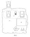
- FIG. 1is a schematic diagram showing a wireless network during manual network configuration of a first player.
- FIG. 2is a schematic diagram showing the wireless network after the first player has joined the network.
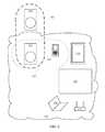
- FIG. 3is a schematic diagram showing the wireless network with the first player in a bridging network with a second player.
- FIG. 4is a schematic diagram showing the wireless network after the second player has joined the network.
- FIG. 5is a schematic diagram showing the wireless network after the controller has discovered the second player.
- FIG. 6is a flowchart of an exemplary method for configuring an audio device to join a wireless network.
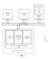
- FIG. 7is a schematic diagram illustrating an example of a system for executing functionality of the present invention.
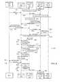
- FIG. 8is a timing diagram illustrating one implementation of the timing for the exemplary method of FIG. 6 .
- network credentialsmay refer to, but not is limited to, the type of network protocol, the network name, the type of security used by that network (WEP, WPA, etc.), and a password for that network.
- a “player”refers to an exemplary audio device, for example, a powered speaker, preamp, amplifier, receiver, etc.
- the term playeris not intended to convey that the audio device is capable, on its own, of rendering an audio signal.
- FIG. 1is a schematic diagram showing a wireless network during manual network configuration of a first player.
- a communications network 210for example, a home WiFi network including a WiFi router 212 or wireless access point, may be in communication with multiple WiFi enabled devices, for example, a smart phone 224 , a laptop computer, 234 , a television 232 , and a tablet computer 240 .
- a first audio device 221 and a second audio device 222are WiFi enabled, but are not configured to communicate with the network 210 .
- the WiFi networkmay be, for example, an IEEE 802.11bgn network, among other possible networks.
- a computing devicefor example, one or more of the smart phone 224 , the laptop computer 234 , and the tablet computer 240 , is configured to run an application controlling one or more audio devices 221 , 222 .
- the smart phone 224is hosting the controller application, and may be referred to hereafter as the controller 224 .
- the controller 224allows a user of the controller application to control and/or configure one or more audio devices, for example, the audio devices 221 , 222 .
- the audio devices 221 , 222may be, for example, speakers containing audio amplifiers and a WiFi interface configured to render a received music stream.
- the audio devices 221 , 222may render a music stream received from the controller 224 or another streaming source via the network 210 . While the described embodiments herein generally include players as audio devices for exemplary purposes, audio devices are not limited to players, and may also include other WiFi enabled audio devices, for example, pre-amplifiers and/or audio processors.
- the audio devices 221 , 222may both be a single type of device, or they may be different types of devices.
- the controller 224may allow a user of the controller 224 to control the audio devices 221 , 222 .
- the user of the controller 224may use the controller 224 to control operating parameters of the audio devices 221 , 222 , such as volume, balance, and/or equalization.
- the controller 224may directly stream program material, such as an audio stream, to the audio devices 221 , 222 , or may select program material to be streamed to the audio devices 221 , 222 from an internet source via the router 212 of the WiFi network 210 .
- the audio devices 221 , 222may include a processor or a computer system 500 ( FIG. 7 ), described further below.
- the audio devices 221 , 222are not configured to communicate via the network 210 , so the controller 224 may communicate with the players 221 , 222 via another means, for example, a Bluetooth connection or a hard-wired connection.
- the controller 224may be physically connected to the first audio device 221 via a cable 120 , for example, an analog audio cable, an ethernet cable, or a Universal Serial Bus (USB) cable.
- the controller 224establishes a communication channel with the first player 221 over the cable 120 , for example, a duplex communication channel.
- the controller 224may provide network credentials for the network 210 to the first audio device 221 over the cable 210 .
- the controller 224may have received the provided network credentials from the user 225 when the user 225 provisions the first audio device 221 to access the WiFi network 210 .
- the first audio device 221establishes a connection with the network 210 (“joins the network”) with the provided network credentials, as shown in FIG. 2 .
- the cable 120 ( FIG. 1 ) between the controller 224 and the first audio device 221may optionally be disconnected.
- the controller 224discovers the first player 221 , and adds the first audio device 221 to a group 220 .
- the group 220may include the controller 224 and one or more audio devices that may be configured by and/or controlled by the controller 224 . As shown in FIG. 2 , the group 220 includes the audio device 221 and the controller 224 .
- the groupmay be, for example, a collection of one or more audio and/or video devices that are configured to collectively render a multi-channel audio and/or audio/video program, for example, a stereo pair, a stereo pair with subwoofer ( 2 . 1 ), a surround system including front, rear, center, and subwoofer speakers ( 5 . 1 , 7 . 1 , 7 . 2 ), among other collections.
- Each device in the group 220may be configured by the controller 224 to render one or more channels of the multi-channel audio and/or audio/video program.
- FIG. 6is a flowchart of an exemplary embodiment of a method to wirelessly add a second player 222 ( FIG. 2 ) to the network 210 ( FIG. 2 ).
- any process descriptions or blocks in flowchartsshould be understood as representing modules, segments, portions of code, or steps that include one or more instructions for implementing specific logical functions in the process, and alternative implementations are included within the scope of the present invention in which functions may be executed out of order from that shown or discussed, including substantially concurrently or in reverse order, depending on the functionality involved, as would be understood by those reasonably skilled in the art of the present invention.
- the methodis described here referencing FIGS. 2-5 .
- a first audio device (audio device 221 ) on the networkis given notice that a second audio device (audio device 222 ) not on the network is available, as shown by block 610 .
- a usermay use a graphical user interface (GUI) on a controller application on the smart phone (controller) 224 to notify the application on the controller 224 that the second audio device 222 is available, and the controller 224 may transmit a notice message to the first audio device 221 .
- the first audio device 221provides a bridge network 320 ( FIG. 3 ), as shown by block 620 .
- the bridge network 320may be a wireless network distinct from the network 212 .
- the bridge network 320may be WiFi, BlueTooth, ZigBee, RF, or another wireless network protocol.
- the bridge network 320or temporary access point (AP), is generally a short duration network, where the bridge network is established temporarily during a configuration time window, and disabled after configuration is complete.
- the bridge network 320includes a proprietary protocol, so that only pre-configured audio devices will recognize and/or be recognized by the bridge network 320 .
- the second audio device 222detects the first audio device 221 and connects to the bridge network 320 , for example, using a pre-shared key (PSK).
- PSKpre-shared key
- a bridge communication channelis established between the first audio device 221 and the second audio device 222 via the bridge network 320 , as shown by block 630 .
- the first audio device 221may notify the controller 224 that the first audio device 221 has established a bridge channel over the bridge network 320 with the second audio device 222 .
- the user of the controller 224may be prompted by the controller 224 to request the second audio device 222 to initiate a handshake with the first audio device 221 over the bridge network 320 so that the first audio device 221 and second audio device 222 can exchange network credentials.
- the application on the controller 224may display a visual prompt via the controller application GUI instructing the user to manually initiate the handshake by pushing a button on the second audio device 222 .
- the second audio device 222may alert the user to manually initiate the handshake, for example, with a flashing LED or an audio signal such as a loud beep, or even by playing a pre-recorded audio message. The user may respond to this alert by manually initiating the handshake via a button push on the second audio device 222 .
- the first audio device 221provides network credentials for the network 210 to the second audio device 222 over the bridge network 320 channel, as shown by block 640 .
- the second audio device 222establishes connection to the network 210 using the network credentials provided to the second audio device 222 by the first audio device 221 , as shown by block 650 and FIG. 4 .
- the bridge network 320may be discontinued after the second audio device 222 has joined the network 210 .
- the controller 224may discover the second audio device 222 on the network 210 , for example, using a discovery protocol. Once the controller 224 has discovered the second audio device 222 , the controller application on the controller 224 may add the second audio device 222 to the group 220 .
- the controller 224may assign an audio channel to be reproduced by the second audio device, where the audio channel is one of two or more audio channels rendering an audio and/or video program by the group 220 .
- FIG. 5is a schematic diagram showing the wireless network after the controller 224 has discovered the second audio device 222 .
- FIG. 8is a timing diagram 800 illustrating one implementation of the timing for the exemplary method 600 for discovery by the first audio device 221 and the controller 224 of a second audio device 222 in a WiFi network.
- any process descriptions, actions or blocks in timing diagramsshould be understood as representing modules, segments, portions of code, or steps that include one or more instructions for implementing specific logical functions in the process, and alternative implementations are included within the scope of the present invention in which functions may be executed out of order from that shown or discussed, including substantially concurrently or in reverse order, depending on the functionality involved, as would be understood by those reasonably skilled in the art of the present invention.
- the timing diagram 800includes actions between system entities, indicated by arrows 801 - 827 , and actions performed by a single system entity, as shown by blocks 830 - 837 .
- the user 225turns on the second audio device 222 , as shown by action 801 , and the second audio device may detect that it does not have a working network connection, for example, by detecting the Ethernet link is down, or by finding no DHCP server, as shown by block 830 .
- the user 255then adds a device to the controller 224 , as shown by action 801 .
- the user 255may use a graphical user interface of the controller 224 to notify the controller 224 to add the second audio device 222 to a list of devices.
- the specific behavior described abovemay depend on whether or not the first audio device 221 has network SSID and Password information. For example, depending upon the specific network, the user 225 may enter a network password and/or SSID that the controller 224 is using.
- the controller 224notifies the previously configured first audio device 221 to start an invitation process, as shown by action 803 .
- the configured first audio device 221starts a temporary access point (AP), or bridge network, including a vendor specific information element (IE), as shown by block 831 .
- the second audio device 222scans the temporary AP with the vendor specific IE, as shown by block 832 .
- the second audio device 222finds the first audio device 221 on the bridge network and the second audio device 222 connects to the first audio device 221 on the bridge network with a generated pre-shared key (PSK), as shown by action 804 .
- PSKpre-shared key
- the first audio device 221notifies the controller 224 that an un-configured device, namely the second audio device 222 , has been detected, as shown by action 805 .
- the controller 224notifies the user 225 that the second audio device 222 is available to connect on the network, as shown by action 806 .
- This notificationmay be, for example, via the GUI of the controller 224 , or via other notification means, for example, an audible or visual indicator on the controller, 224 , the first audio device 221 , and/or the second audio device 222 .
- the connection of the second audio device 222 to the networkis then initiated by the user 225 , for example, by pushing a connect button or another actuator on the second audio device, as shown by action 807 .
- the second audio device 222generates a DHCP request to the first audio device 221 , for example, via the bridge network, as shown by action 808 , and the second audio device 222 passes the DHCP request to a network router having a DHCP server, for example, the WiFi router 212 , as shown by action 809 .
- the second audio device 222may initiate an DHCP client and send a “DHCP discover” command to the DHCP server of the WiFi router 212 via the configured first audio device 221 .
- the WiFi router 212forwards an IP address to the first audio device 221 , as shown by action 810 , and the first audio device 221 passes the IP address to the second audio device 222 , as shown by action 811 .
- the WiFi router 212 DHCP serversends a response “DHCP offer” command to the second audio device 222 via the configured first audio device 221 .
- the IP address of the second audio device 222is assigned.
- the second audio device 222connects to the WiFi router 212 via the WiFi network using the received IP address, so the controller 224 , the first audio device 221 , the second audio device 222 , and the WiFi router 212 may all communicate via the WiFi network, as shown by block 833 .
- the second audio device 222starts UPnP (Universal Plug and Play) function for configuring, as shown by block 834 , and sends a “SSDP (Simple Service Discovery Protocol) notify” command to the controller 224 , as shown by action 812 .
- the controller 224configures the second audio device 222 with UPnP commands, as shown by actions 813 and 814 .
- the controller 224may retrieve information for a home AP, for example, the SSID and/or password from the first audio device 221 , as shown by actions 815 and 816 .
- a home APis typically an existing local hardware device called a “router” or “wi-fi router” that provides network access to devices located within the home via wired and wireless connections. It allows the devices on the local network to access an external network such as the Internet via it's built-in routing and bridging functions.
- the controller 224sends the home AP information to the second audio device 222 , as shown by action 817 .
- the second audio device 222connects to the home AP, as shown by block 835 . If the connection fails, the second audio device 222 front panel indicator may indicate an alert, for example, with a flashing light. Otherwise the second audio device notifies the controller 224 of the SSDP, as shown by action 818 .
- the controller 224may request and receive configuration status from the second audio device 222 , as shown by actions 819 and 820 .
- the controller 224declares the second audio device 222 as being found, as shown by block 836 , and notifies the user that the second audio device 222 is configured, and the second audio device 222 should be closed to the home AP, as shown by action 821 .
- the user 225may forward a name for the second audio device 222 to the controller 224 , as shown by action 222 .
- the controller 224may then negotiate with the second audio device 222 to set the name of the second audio device 222 , as shown by actions 823 - 826 .
- the controller 224may request a configuration token from the second audio device 222 with a GetConfigurationToken command, as shown by action 823 , and the second audio device 222 may respond by sending a configuration token to the controller 224 , as shown by action 824 .
- the configuration tokenmay include information indicating the current configuration state of the second audio device 222 .
- the controller 224may compare the information indicating the current configuration state of the second audio device 222 , and send the second audio device 222 a name change command (SetFriendlyName, as per action 825 ), and may further update the configuration of the second audio device 221 via an ApplyChanges command, as shown by action 226 .
- the controller 224sends a “Stop Invitation” command to the first audio device 221 , as shown by action 827 .
- the first audio device 221stops the temporary (bridge) AP, as shown by block 837 .
- the present system for executing the functionality of the audio devices 221 , 222 ( FIGS. 2-5 ) described in detail abovemay be a computer, an example of which is shown in the schematic diagram of FIG. 5 .
- the system 500contains a processor 502 , a storage device 504 , a memory 506 having software 508 stored therein that defines the abovementioned functionality, input and output (I/O) devices 510 (or peripherals), and a local bus, or local interface 512 allowing for communication within the system 500 .
- the local interface 512can be, for example but not limited to, one or more buses or other wired or wireless connections, as is known in the art.
- the local interface 512may have additional elements, which are omitted for simplicity, such as controllers, buffers (caches), drivers, repeaters, and receivers, to enable communications. Further, the local interface 512 may include address, control, and/or data connections to enable appropriate communications among the aforementioned components.
- the processor 502is a hardware device for executing software, particularly that stored in the memory 506 .
- the processor 502can be any custom made or commercially available single core or multi-core processor, a central processing unit (CPU), an auxiliary processor among several processors associated with the present system 500 , a semiconductor based microprocessor (in the form of a microchip or chip set), a macroprocessor, or generally any device for executing software instructions.
- the memory 506can include any one or combination of volatile memory elements (e.g., random access memory (RAM, such as DRAM, SRAM, SDRAM, etc.)) and nonvolatile memory elements (e.g., ROM, hard drive, tape, CDROM, etc.). Moreover, the memory 506 may incorporate electronic, magnetic, optical, and/or other types of storage media. Note that the memory 506 can have a distributed architecture, where various components are situated remotely from one another, but can be accessed by the processor 502 .
- the software 508defines functionality performed by the system 500 , in accordance with the present invention.
- the software 508 in the memory 506may include one or more separate programs, each of which contains an ordered listing of executable instructions for implementing logical functions of the system 500 , as described below.
- the memory 506may contain an operating system (O/S) 520 .
- the operating systemessentially controls the execution of programs within the system 500 and provides scheduling, input-output control, file and data management, memory management, and communication control and related services.
- the I/O devices 510may include input devices, for example but not limited to, a keyboard, mouse, scanner, microphone, etc. Furthermore, the I/O devices 510 may also include output devices, for example but not limited to, a printer, display, etc. The I/O devices 510 may further include devices that communicate via both inputs and outputs, for instance but not limited to, a modulator/demodulator (modem; for accessing another device, system, or network), a radio frequency (RF) or other transceiver, a telephonic interface, a bridge, a router, or other device.
- modemfor accessing another device, system, or network
- RFradio frequency
- the I/O devices 510include a communication processor 528 .
- the communication processormay control and/or include a Wi-Fi interface 522 , for example, but not limited to an interface configured to an IEEE 802.11bgn network interface, among other possible wireless network interfaces.
- a bridge network interface 524is configured to provide wireless communication independently of the Wi-Fi interface 522 , as described above.
- a cable interface 526provides a hard-wired communications interface, for example, between the players 221 , 222 and the controller application.
- the processor 502When the system 500 is in operation, the processor 502 is configured to execute the software 508 stored within the memory 506 to communicate data to and from the memory 506 , and to generally control operations of the system 500 pursuant to the software 508 , as explained above.
- the processor 502When the functionality of the system 500 is in operation, the processor 502 is configured to execute the software 508 stored within the memory 506 , to communicate data to and from the memory 506 , and to generally control operations of the system 500 pursuant to the software 508 .
- the operating system 520is read by the processor 502 , perhaps buffered within the processor 502 , and then executed.
- a computer-readable mediumfor use by or in connection with any computer-related device, system, or method.
- Such a computer-readable mediummay, in some embodiments, correspond to either or both the memory 506 or the storage device 504 .
- a computer-readable mediumis an electronic, magnetic, optical, or other physical device or means that can contain or store a computer program for use by or in connection with a computer-related device, system, or method.
- Instructions for implementing the systemcan be embodied in any computer-readable medium for use by or in connection with the processor or other such instruction execution system, apparatus, or device.
- such instruction execution system, apparatus, or devicemay, in some embodiments, be any computer-based system, processor-containing system, or other system that can fetch the instructions from the instruction execution system, apparatus, or device and execute the instructions.
- a “computer-readable medium”can be any means that can store, communicate, propagate, or transport the program for use by or in connection with the processor or other such instruction execution system, apparatus, or device.
- Such a computer-readable mediumcan be, for example but not limited to, an electronic, magnetic, optical, electromagnetic, infrared, or semiconductor system, apparatus, device, or propagation medium. More specific examples (a nonexhaustive list) of the computer-readable medium would include the following: an electrical connection (electronic) having one or more wires, a portable computer diskette (magnetic), a random access memory (RAM) (electronic), a read-only memory (ROM) (electronic), an erasable programmable read-only memory (EPROM, EEPROM, or Flash memory) (electronic), an optical fiber (optical), and a portable compact disc read-only memory (CDROM) (optical).
- an electrical connectionhaving one or more wires
- a portable computer diskettemagnetic
- RAMrandom access memory
- ROMread-only memory
- EPROMerasable programmable read-only memory
- EPROMerasable programmable read-only memory
- CDROMportable compact disc read-only memory
- the computer-readable mediumcould even be paper or another suitable medium upon which the program is printed, as the program can be electronically captured, via for instance optical scanning of the paper or other medium, then compiled, interpreted or otherwise processed in a suitable manner if necessary, and then stored in a computer memory.
- system 500can be implemented with any or a combination of the following technologies, which are each well known in the art: a discreet logic circuit(s) having logic gates for implementing logic functions upon data signals, an application specific integrated circuit (ASIC) having appropriate combinational logic gates, a programmable gate array(s) (PGA), a field programmable gate array (FPGA), etc.
- ASICapplication specific integrated circuit
- PGAprogrammable gate array
- FPGAfield programmable gate array
Landscapes
- Engineering & Computer Science (AREA)
- Signal Processing (AREA)
- Computer Networks & Wireless Communication (AREA)
- Automation & Control Theory (AREA)
- Health & Medical Sciences (AREA)
- General Health & Medical Sciences (AREA)
- Otolaryngology (AREA)
- Physics & Mathematics (AREA)
- Acoustics & Sound (AREA)
- Mobile Radio Communication Systems (AREA)
- Human Computer Interaction (AREA)
Abstract
Description
Claims (15)
Priority Applications (1)
| Application Number | Priority Date | Filing Date | Title |
|---|---|---|---|
| US15/152,649US9999091B2 (en) | 2015-05-12 | 2016-05-12 | System and method for negotiating group membership for audio controllers |
Applications Claiming Priority (2)
| Application Number | Priority Date | Filing Date | Title |
|---|---|---|---|
| US201562160204P | 2015-05-12 | 2015-05-12 | |
| US15/152,649US9999091B2 (en) | 2015-05-12 | 2016-05-12 | System and method for negotiating group membership for audio controllers |
Publications (2)
| Publication Number | Publication Date |
|---|---|
| US20160337190A1 US20160337190A1 (en) | 2016-11-17 |
| US9999091B2true US9999091B2 (en) | 2018-06-12 |
Family
ID=57248541
Family Applications (1)
| Application Number | Title | Priority Date | Filing Date |
|---|---|---|---|
| US15/152,649Active2036-08-02US9999091B2 (en) | 2015-05-12 | 2016-05-12 | System and method for negotiating group membership for audio controllers |
Country Status (3)
| Country | Link |
|---|---|
| US (1) | US9999091B2 (en) |
| EP (1) | EP3295577A4 (en) |
| WO (1) | WO2016183263A1 (en) |
Cited By (2)
| Publication number | Priority date | Publication date | Assignee | Title |
|---|---|---|---|---|
| US11113022B2 (en)* | 2015-05-12 | 2021-09-07 | D&M Holdings, Inc. | Method, system and interface for controlling a subwoofer in a networked audio system |
| US11209972B2 (en) | 2015-09-02 | 2021-12-28 | D&M Holdings, Inc. | Combined tablet screen drag-and-drop interface |
Families Citing this family (8)
| Publication number | Priority date | Publication date | Assignee | Title |
|---|---|---|---|---|
| US10403253B2 (en)* | 2014-12-19 | 2019-09-03 | Teac Corporation | Portable recording/reproducing apparatus with wireless LAN function and recording/reproduction system with wireless LAN function |
| JP6631078B2 (en)* | 2015-06-16 | 2020-01-15 | ヤマハ株式会社 | Audio device connection method, audio device, audio system control program, and control terminal device |
| JP6503973B2 (en)* | 2015-08-19 | 2019-04-24 | ヤマハ株式会社 | Audio device connection method and audio device |
| US10548069B2 (en)* | 2016-08-19 | 2020-01-28 | Harman International Industries, Incorporated | Wireless audio device provisioning |
| CN108134718B (en)* | 2017-11-16 | 2019-07-23 | 百度在线网络技术(北京)有限公司 | Method, apparatus, equipment and the computer storage medium of discovering device |
| US12015498B1 (en)* | 2018-11-09 | 2024-06-18 | Amazon Technologies, Inc. | Electronic device configuration using dummy devices |
| US11490256B2 (en)* | 2019-03-11 | 2022-11-01 | Hewlett Packard Enterprise Development Lp | Secure zero-touch provisioning of network devices in an offline deployment |
| US11394789B2 (en) | 2019-05-08 | 2022-07-19 | Hewlett Packard Enterprise Development Lp | Seamless migration of a network management system deployment to cloud-based deployment |
Citations (46)
| Publication number | Priority date | Publication date | Assignee | Title |
|---|---|---|---|---|
| US5838384A (en) | 1995-07-17 | 1998-11-17 | Gateway 2000, Inc. | System for assigning multichannel audio signals to independent wireless audio output devices |
| US20020055788A1 (en) | 2000-06-02 | 2002-05-09 | Virtual Ink Corporation | Transcription system network |
| US20020101997A1 (en) | 1995-11-06 | 2002-08-01 | Xerox Corporation | Multimedia coordination system |
| US20020170061A1 (en) | 1999-04-14 | 2002-11-14 | Dilorenzo Mark | Multi-room entertainment system with in-room media player |
| US20030208300A1 (en) | 2000-11-28 | 2003-11-06 | Dilorenzo Mark | Electronic media distribution system with media purchase interface |
| US20050111672A1 (en) | 2003-11-25 | 2005-05-26 | Chen-Lee Chen | Speaker matcher for use of multiple rooms |
| US7149549B1 (en) | 2000-10-26 | 2006-12-12 | Ortiz Luis M | Providing multiple perspectives for a venue activity through an electronic hand held device |
| US20080010648A1 (en) | 2005-10-17 | 2008-01-10 | Hideo Ando | Information storage medium, information reproducing apparatus, and information reproducing method |
| US20080313568A1 (en) | 2007-06-12 | 2008-12-18 | Samsung Electronics Co., Ltd. | Digital multimedia playback apparatus and control method thereof |
| US20090187842A1 (en) | 2008-01-22 | 2009-07-23 | 3Dlabs Inc., Ltd. | Drag and Drop User Interface for Portable Electronic Devices with Touch Sensitive Screens |
| US7574691B2 (en) | 2003-03-17 | 2009-08-11 | Macrovision Corporation | Methods and apparatus for rendering user interfaces and display information on remote client devices |
| US20100121919A1 (en) | 2008-11-13 | 2010-05-13 | Arhus Universitet | System and a method for sharing information interactively among two or more users |
| US20100138782A1 (en) | 2008-11-30 | 2010-06-03 | Nokia Corporation | Item and view specific options |
| US7791594B2 (en) | 2006-08-30 | 2010-09-07 | Sony Ericsson Mobile Communications Ab | Orientation based multiple mode mechanically vibrated touch screen display |
| US20100260348A1 (en) | 2009-04-14 | 2010-10-14 | Plantronics, Inc. | Network Addressible Loudspeaker and Audio Play |
| US20100299639A1 (en) | 2008-01-07 | 2010-11-25 | Max Gordon Ramsay | User interface for managing the operation of networked media playback devices |
| US7978176B2 (en) | 2007-01-07 | 2011-07-12 | Apple Inc. | Portrait-landscape rotation heuristics for a portable multifunction device |
| US20110211219A1 (en) | 2009-09-30 | 2011-09-01 | Apple Inc. | Methods and apparatus for solicited activation for protected wireless networking |
| US8111132B2 (en) | 2004-01-06 | 2012-02-07 | Bose Corporation | Remote controlling |
| US8116476B2 (en) | 2007-12-27 | 2012-02-14 | Sony Corporation | Audio signal receiving apparatus, audio signal receiving method and audio signal transmission system |
| US8131389B1 (en) | 2002-02-08 | 2012-03-06 | Digital Voice Systems, Inc. | Digital audio server |
| US8214447B2 (en) | 2004-06-08 | 2012-07-03 | Bose Corporation | Managing an audio network |
| US20120192070A1 (en) | 2011-01-21 | 2012-07-26 | De Faria Manuel Dias Lima | Interactive sound system |
| US8245143B2 (en) | 2008-10-08 | 2012-08-14 | Research In Motion Limited | Method and handheld electronic device having a graphical user interface which arranges icons dynamically |
| US8290172B2 (en) | 2007-01-05 | 2012-10-16 | Audio Design Associates, Inc. | Multi-source distributed audio amplification and control system for structured wiring systems |
| US20130089026A1 (en) | 2011-07-18 | 2013-04-11 | geoffrey Chilton Piper | Wireless Audio Transmission |
| US20130154950A1 (en) | 2011-12-15 | 2013-06-20 | David Kvasnica | Apparatus and method pertaining to display orientation |
| US20130173794A1 (en) | 2011-12-29 | 2013-07-04 | Michael Agerbak | Systems and methods for connecting an audio controller to a hidden audio network |
| US20130187861A1 (en) | 2012-01-19 | 2013-07-25 | Research In Motion Limited | Simultaneous display of multiple maximized applications on touch screen electronic devices |
| US20130340003A1 (en) | 2008-11-07 | 2013-12-19 | Digimarc Corporation | Second screen methods and arrangements |
| US20140009676A1 (en) | 2008-09-02 | 2014-01-09 | Apple Inc. | Systems and methods for saving and restoring scenes in a multimedia system |
| US20140022285A1 (en) | 2012-07-20 | 2014-01-23 | Thomas Jan Stovicek | Handheld device with ergonomic display features |
| US20140078176A1 (en) | 2012-09-14 | 2014-03-20 | Lg Electronics Inc. | Apparatus and method of providing user interface on head mounted display and head mounted display thereof |
| US8724600B2 (en) | 2008-01-07 | 2014-05-13 | Tymphany Hong Kong Limited | Systems and methods for providing a media playback in a networked environment |
| US20140164983A1 (en) | 2012-12-07 | 2014-06-12 | Honeywell International Inc. | System and method for interacting with a touch screen interface utilizing an intelligent stencil mask |
| US8812051B2 (en) | 2011-09-27 | 2014-08-19 | Z124 | Graphical user interfaces cues for optimal datapath selection |
| US8832823B2 (en) | 2012-12-04 | 2014-09-09 | International Business Machines Corporation | User access control based on handheld device orientation |
| US20140283136A1 (en) | 2013-03-13 | 2014-09-18 | Optio Labs, Inc. | Systems and methods for securing and locating computing devices |
| US20140270306A1 (en) | 2013-03-15 | 2014-09-18 | Aliphcom | Proximity sensing device control architecture and data communication protocol |
| US8887071B2 (en) | 2012-12-07 | 2014-11-11 | Eric Yang | Collaborative information sharing system |
| US20140334644A1 (en) | 2013-02-11 | 2014-11-13 | Symphonic Audio Technologies Corp. | Method for augmenting a listening experience |
| US20140355389A1 (en) | 2013-05-29 | 2014-12-04 | Nokia Corporation | Method and apparatus for establishing device communication |
| US9001047B2 (en) | 2007-01-07 | 2015-04-07 | Apple Inc. | Modal change based on orientation of a portable multifunction device |
| US20150181010A1 (en)* | 2013-12-20 | 2015-06-25 | Plantronics, Inc. | Local Wireless Link Quality Notification for Wearable Audio Devices |
| US20150195649A1 (en)* | 2013-12-08 | 2015-07-09 | Flyover Innovations, Llc | Method for proximity based audio device selection |
| US9504076B2 (en)* | 2012-12-21 | 2016-11-22 | Sonova Ag | Pairing method for establishing a wireless audio network |
Family Cites Families (1)
| Publication number | Priority date | Publication date | Assignee | Title |
|---|---|---|---|---|
| AU2007312944A1 (en)* | 2006-10-17 | 2008-04-24 | Altec Lansing Australia Pty Ltd | Configuring and connecting to a media wireless network |
- 2016
- 2016-05-12EPEP16793488.4Apatent/EP3295577A4/ennot_activeWithdrawn
- 2016-05-12WOPCT/US2016/031964patent/WO2016183263A1/ennot_activeCeased
- 2016-05-12USUS15/152,649patent/US9999091B2/enactiveActive
Patent Citations (48)
| Publication number | Priority date | Publication date | Assignee | Title |
|---|---|---|---|---|
| US5838384A (en) | 1995-07-17 | 1998-11-17 | Gateway 2000, Inc. | System for assigning multichannel audio signals to independent wireless audio output devices |
| US20020101997A1 (en) | 1995-11-06 | 2002-08-01 | Xerox Corporation | Multimedia coordination system |
| US20020170061A1 (en) | 1999-04-14 | 2002-11-14 | Dilorenzo Mark | Multi-room entertainment system with in-room media player |
| US6650963B2 (en) | 1999-04-14 | 2003-11-18 | Dilorenzo Mark | Multi-room entertainment system with in-room media player |
| US20020055788A1 (en) | 2000-06-02 | 2002-05-09 | Virtual Ink Corporation | Transcription system network |
| US7149549B1 (en) | 2000-10-26 | 2006-12-12 | Ortiz Luis M | Providing multiple perspectives for a venue activity through an electronic hand held device |
| US20030208300A1 (en) | 2000-11-28 | 2003-11-06 | Dilorenzo Mark | Electronic media distribution system with media purchase interface |
| US8131389B1 (en) | 2002-02-08 | 2012-03-06 | Digital Voice Systems, Inc. | Digital audio server |
| US7574691B2 (en) | 2003-03-17 | 2009-08-11 | Macrovision Corporation | Methods and apparatus for rendering user interfaces and display information on remote client devices |
| US20050111672A1 (en) | 2003-11-25 | 2005-05-26 | Chen-Lee Chen | Speaker matcher for use of multiple rooms |
| US8111132B2 (en) | 2004-01-06 | 2012-02-07 | Bose Corporation | Remote controlling |
| US8214447B2 (en) | 2004-06-08 | 2012-07-03 | Bose Corporation | Managing an audio network |
| US20080010648A1 (en) | 2005-10-17 | 2008-01-10 | Hideo Ando | Information storage medium, information reproducing apparatus, and information reproducing method |
| US7791594B2 (en) | 2006-08-30 | 2010-09-07 | Sony Ericsson Mobile Communications Ab | Orientation based multiple mode mechanically vibrated touch screen display |
| US8290172B2 (en) | 2007-01-05 | 2012-10-16 | Audio Design Associates, Inc. | Multi-source distributed audio amplification and control system for structured wiring systems |
| US9001047B2 (en) | 2007-01-07 | 2015-04-07 | Apple Inc. | Modal change based on orientation of a portable multifunction device |
| US7978176B2 (en) | 2007-01-07 | 2011-07-12 | Apple Inc. | Portrait-landscape rotation heuristics for a portable multifunction device |
| US20080313568A1 (en) | 2007-06-12 | 2008-12-18 | Samsung Electronics Co., Ltd. | Digital multimedia playback apparatus and control method thereof |
| US8116476B2 (en) | 2007-12-27 | 2012-02-14 | Sony Corporation | Audio signal receiving apparatus, audio signal receiving method and audio signal transmission system |
| US20100299639A1 (en) | 2008-01-07 | 2010-11-25 | Max Gordon Ramsay | User interface for managing the operation of networked media playback devices |
| US8724600B2 (en) | 2008-01-07 | 2014-05-13 | Tymphany Hong Kong Limited | Systems and methods for providing a media playback in a networked environment |
| US20090187842A1 (en) | 2008-01-22 | 2009-07-23 | 3Dlabs Inc., Ltd. | Drag and Drop User Interface for Portable Electronic Devices with Touch Sensitive Screens |
| US20140009676A1 (en) | 2008-09-02 | 2014-01-09 | Apple Inc. | Systems and methods for saving and restoring scenes in a multimedia system |
| US8245143B2 (en) | 2008-10-08 | 2012-08-14 | Research In Motion Limited | Method and handheld electronic device having a graphical user interface which arranges icons dynamically |
| US20130340003A1 (en) | 2008-11-07 | 2013-12-19 | Digimarc Corporation | Second screen methods and arrangements |
| US20100121919A1 (en) | 2008-11-13 | 2010-05-13 | Arhus Universitet | System and a method for sharing information interactively among two or more users |
| US20100138782A1 (en) | 2008-11-30 | 2010-06-03 | Nokia Corporation | Item and view specific options |
| US20120269361A1 (en) | 2009-04-14 | 2012-10-25 | Plantronics, Inc. | Network Addressible Loudspeaker and Audio Play |
| US20100260348A1 (en) | 2009-04-14 | 2010-10-14 | Plantronics, Inc. | Network Addressible Loudspeaker and Audio Play |
| US20110211219A1 (en) | 2009-09-30 | 2011-09-01 | Apple Inc. | Methods and apparatus for solicited activation for protected wireless networking |
| US20120192070A1 (en) | 2011-01-21 | 2012-07-26 | De Faria Manuel Dias Lima | Interactive sound system |
| US20130089026A1 (en) | 2011-07-18 | 2013-04-11 | geoffrey Chilton Piper | Wireless Audio Transmission |
| US8812051B2 (en) | 2011-09-27 | 2014-08-19 | Z124 | Graphical user interfaces cues for optimal datapath selection |
| US20130154950A1 (en) | 2011-12-15 | 2013-06-20 | David Kvasnica | Apparatus and method pertaining to display orientation |
| US20130173794A1 (en) | 2011-12-29 | 2013-07-04 | Michael Agerbak | Systems and methods for connecting an audio controller to a hidden audio network |
| US20130187861A1 (en) | 2012-01-19 | 2013-07-25 | Research In Motion Limited | Simultaneous display of multiple maximized applications on touch screen electronic devices |
| US20140022285A1 (en) | 2012-07-20 | 2014-01-23 | Thomas Jan Stovicek | Handheld device with ergonomic display features |
| US20140078176A1 (en) | 2012-09-14 | 2014-03-20 | Lg Electronics Inc. | Apparatus and method of providing user interface on head mounted display and head mounted display thereof |
| US8832823B2 (en) | 2012-12-04 | 2014-09-09 | International Business Machines Corporation | User access control based on handheld device orientation |
| US20140164983A1 (en) | 2012-12-07 | 2014-06-12 | Honeywell International Inc. | System and method for interacting with a touch screen interface utilizing an intelligent stencil mask |
| US8887071B2 (en) | 2012-12-07 | 2014-11-11 | Eric Yang | Collaborative information sharing system |
| US9504076B2 (en)* | 2012-12-21 | 2016-11-22 | Sonova Ag | Pairing method for establishing a wireless audio network |
| US20140334644A1 (en) | 2013-02-11 | 2014-11-13 | Symphonic Audio Technologies Corp. | Method for augmenting a listening experience |
| US20140283136A1 (en) | 2013-03-13 | 2014-09-18 | Optio Labs, Inc. | Systems and methods for securing and locating computing devices |
| US20140270306A1 (en) | 2013-03-15 | 2014-09-18 | Aliphcom | Proximity sensing device control architecture and data communication protocol |
| US20140355389A1 (en) | 2013-05-29 | 2014-12-04 | Nokia Corporation | Method and apparatus for establishing device communication |
| US20150195649A1 (en)* | 2013-12-08 | 2015-07-09 | Flyover Innovations, Llc | Method for proximity based audio device selection |
| US20150181010A1 (en)* | 2013-12-20 | 2015-06-25 | Plantronics, Inc. | Local Wireless Link Quality Notification for Wearable Audio Devices |
Non-Patent Citations (5)
| Title |
|---|
| Cheng, et al. IrotateGrasp: automatic screen rotation based on grasp of mobile devices. Proceedings of the SIGCHI conference on Human Factors in computing Systems; 3051-3054; 2013. |
| International Search Report and Written Opinion for PCT/US16/32092 dated Oct. 14, 2016. |
| International Search Report and Written Opinion for PCT/US16/49425 dated Oct. 28, 2016. |
| International Search Report for PCT/US16/31964 dated Aug. 18, 2016. |
| Kim et al; Huffman user interface for fill touch screen based mobile phones. Proceedings of the 12th International Conference on Advanced Communication Technology; 1021-1026; 2010. |
Cited By (2)
| Publication number | Priority date | Publication date | Assignee | Title |
|---|---|---|---|---|
| US11113022B2 (en)* | 2015-05-12 | 2021-09-07 | D&M Holdings, Inc. | Method, system and interface for controlling a subwoofer in a networked audio system |
| US11209972B2 (en) | 2015-09-02 | 2021-12-28 | D&M Holdings, Inc. | Combined tablet screen drag-and-drop interface |
Also Published As
| Publication number | Publication date |
|---|---|
| WO2016183263A1 (en) | 2016-11-17 |
| US20160337190A1 (en) | 2016-11-17 |
| EP3295577A4 (en) | 2018-10-10 |
| EP3295577A1 (en) | 2018-03-21 |
Similar Documents
| Publication | Publication Date | Title |
|---|---|---|
| US9999091B2 (en) | System and method for negotiating group membership for audio controllers | |
| JP5980805B2 (en) | Wireless network interface with infrastructure and direct mode | |
| CN104115449B (en) | System and method for Audio Controller is connected with concealing audio network | |
| US8848106B2 (en) | Communication device, communication system, communication method, control program, and television receiving system | |
| CN107249174B (en) | Communication connection establishment method and terminal | |
| US20130311692A1 (en) | Apparatus and method for direct pairing in a wireless docking system | |
| CN105636237B (en) | A kind of method, wireless device, system and storage medium for connecting network | |
| JP7102311B2 (en) | Communication equipment, control methods for communication equipment, and programs | |
| CN104717225B (en) | A kind of things-internet gateway access authentication method and system | |
| US20060281477A1 (en) | Dynamic detection and configuration of networked audio/video components | |
| TW201502787A (en) | Communication between host and accessory devices using accessory protocols via wireless transport | |
| CN102598837B (en) | host-initiated device connection | |
| US20190297119A1 (en) | Establishing direct secure connection between collaboration devices in a room or space | |
| WO2016180091A1 (en) | Network access method and device | |
| CN115119190A (en) | Bluetooth connection method, device, computer equipment and readable storage medium | |
| EP4380197A1 (en) | Device networking and sound channel configuration method and electronic device | |
| WO2017185339A1 (en) | Wireless connection method, apparatus and system | |
| CN105812185A (en) | A communication connection method for a playback device | |
| US9549429B1 (en) | Wireless network interconnection | |
| US9900829B2 (en) | Communication device, method for controlling the communication device, and program | |
| JP6001586B2 (en) | Device device setting method in gateway device, gateway device, and device device setting program | |
| TWI477179B (en) | Wireless apparatus, wireless network architecture and network connection method with automatic connection settings | |
| US20170238196A1 (en) | Communication device and communication system | |
| CN119835103A (en) | Equipment communication method, device, equipment, system and storage medium | |
| CN118233228A (en) | A network configuration method, device and system |
Legal Events
| Date | Code | Title | Description |
|---|---|---|---|
| AS | Assignment | Owner name:D&M HOLDINGS, INC., JAPAN Free format text:ASSIGNMENT OF ASSIGNORS INTEREST;ASSIGNORS:WACHTER, MARTIN RICHARD;YAMANOUCHI, RYOUICHI;BAXTER, SAMUEL;SIGNING DATES FROM 20150515 TO 20150728;REEL/FRAME:038556/0817 | |
| AS | Assignment | Owner name:SOUND UNITED, LLC, CALIFORNIA Free format text:GRANT OF SECURITY INTEREST;ASSIGNOR:D&M HOLDINGS INC.;REEL/FRAME:042622/0011 Effective date:20170526 | |
| STCF | Information on status: patent grant | Free format text:PATENTED CASE | |
| AS | Assignment | Owner name:D&M HOLDINGS INC, JAPAN Free format text:RELEASE OF SECURITY INTEREST IN PATENTS;ASSIGNOR:SOUND UNITED, LLC;REEL/FRAME:054858/0361 Effective date:20201224 | |
| AS | Assignment | Owner name:CERBERUS BUSINESS FINANCE, LLC, AS COLLATERAL AGENT, NEW YORK Free format text:NOTICE OF SECURITY INTEREST - - PATENTS;ASSIGNOR:D&M HOLDINGS INC.;REEL/FRAME:054874/0184 Effective date:20201228 | |
| MAFP | Maintenance fee payment | Free format text:PAYMENT OF MAINTENANCE FEE, 4TH YEAR, LARGE ENTITY (ORIGINAL EVENT CODE: M1551); ENTITY STATUS OF PATENT OWNER: LARGE ENTITY Year of fee payment:4 | |
| AS | Assignment | Owner name:D&M HOLDINGS INC., CALIFORNIA Free format text:RELEASE OF SECURITY INTEREST IN INTELLECTUAL PROPERTY;ASSIGNOR:CERBERUS BUSINESS FINANCE, LLC, AS AGENT;REEL/FRAME:059127/0278 Effective date:20210429 Owner name:B & W LOUDSPEAKERS LTD, UNITED KINGDOM Free format text:RELEASE OF SECURITY INTEREST IN INTELLECTUAL PROPERTY;ASSIGNOR:CERBERUS BUSINESS FINANCE, LLC, AS AGENT;REEL/FRAME:059127/0278 Effective date:20210429 Owner name:SOUND UNITED, LLC, CALIFORNIA Free format text:RELEASE OF SECURITY INTEREST IN INTELLECTUAL PROPERTY;ASSIGNOR:CERBERUS BUSINESS FINANCE, LLC, AS AGENT;REEL/FRAME:059127/0278 Effective date:20210429 Owner name:B & W GROUP LTD, UNITED KINGDOM Free format text:RELEASE OF SECURITY INTEREST IN INTELLECTUAL PROPERTY;ASSIGNOR:CERBERUS BUSINESS FINANCE, LLC, AS AGENT;REEL/FRAME:059127/0278 Effective date:20210429 Owner name:D&M EUROPE B.V., CALIFORNIA Free format text:RELEASE OF SECURITY INTEREST IN INTELLECTUAL PROPERTY;ASSIGNOR:CERBERUS BUSINESS FINANCE, LLC, AS AGENT;REEL/FRAME:059127/0278 Effective date:20210429 Owner name:BOSTON ACOUSTICS, INC., CALIFORNIA Free format text:RELEASE OF SECURITY INTEREST IN INTELLECTUAL PROPERTY;ASSIGNOR:CERBERUS BUSINESS FINANCE, LLC, AS AGENT;REEL/FRAME:059127/0278 Effective date:20210429 Owner name:DEFINITIVE TECHNOLOGY, LLC, CALIFORNIA Free format text:RELEASE OF SECURITY INTEREST IN INTELLECTUAL PROPERTY;ASSIGNOR:CERBERUS BUSINESS FINANCE, LLC, AS AGENT;REEL/FRAME:059127/0278 Effective date:20210429 Owner name:DIRECTED, LLC, CALIFORNIA Free format text:RELEASE OF SECURITY INTEREST IN INTELLECTUAL PROPERTY;ASSIGNOR:CERBERUS BUSINESS FINANCE, LLC, AS AGENT;REEL/FRAME:059127/0278 Effective date:20210429 Owner name:POLK AUDIO, LLC, CALIFORNIA Free format text:RELEASE OF SECURITY INTEREST IN INTELLECTUAL PROPERTY;ASSIGNOR:CERBERUS BUSINESS FINANCE, LLC, AS AGENT;REEL/FRAME:059127/0278 Effective date:20210429 |