US9998246B2 - Simultaneous transmission on shared channel - Google Patents
Simultaneous transmission on shared channelDownload PDFInfo
- Publication number
- US9998246B2 US9998246B2US14/657,942US201514657942AUS9998246B2US 9998246 B2US9998246 B2US 9998246B2US 201514657942 AUS201514657942 AUS 201514657942AUS 9998246 B2US9998246 B2US 9998246B2
- Authority
- US
- United States
- Prior art keywords
- radios
- axis response
- collocated
- axis
- radio
- Prior art date
- Legal status (The legal status is an assumption and is not a legal conclusion. Google has not performed a legal analysis and makes no representation as to the accuracy of the status listed.)
- Active
Links
Images


Classifications
- H—ELECTRICITY
- H04—ELECTRIC COMMUNICATION TECHNIQUE
- H04J—MULTIPLEX COMMUNICATION
- H04J3/00—Time-division multiplex systems
- H04J3/02—Details
- H04J3/06—Synchronising arrangements
- H04J3/0635—Clock or time synchronisation in a network
- H04J3/0676—Mutual
- H—ELECTRICITY
- H01—ELECTRIC ELEMENTS
- H01Q—ANTENNAS, i.e. RADIO AERIALS
- H01Q1/00—Details of, or arrangements associated with, antennas
- H01Q1/40—Radiating elements coated with or embedded in protective material
- H—ELECTRICITY
- H01—ELECTRIC ELEMENTS
- H01Q—ANTENNAS, i.e. RADIO AERIALS
- H01Q17/00—Devices for absorbing waves radiated from an antenna; Combinations of such devices with active antenna elements or systems
- H—ELECTRICITY
- H01—ELECTRIC ELEMENTS
- H01Q—ANTENNAS, i.e. RADIO AERIALS
- H01Q19/00—Combinations of primary active antenna elements and units with secondary devices, e.g. with quasi-optical devices, for giving the antenna a desired directional characteristic
- H01Q19/10—Combinations of primary active antenna elements and units with secondary devices, e.g. with quasi-optical devices, for giving the antenna a desired directional characteristic using reflecting surfaces
- H01Q19/18—Combinations of primary active antenna elements and units with secondary devices, e.g. with quasi-optical devices, for giving the antenna a desired directional characteristic using reflecting surfaces having two or more spaced reflecting surfaces
- H01Q19/19—Combinations of primary active antenna elements and units with secondary devices, e.g. with quasi-optical devices, for giving the antenna a desired directional characteristic using reflecting surfaces having two or more spaced reflecting surfaces comprising one main concave reflecting surface associated with an auxiliary reflecting surface
- H—ELECTRICITY
- H04—ELECTRIC COMMUNICATION TECHNIQUE
- H04L—TRANSMISSION OF DIGITAL INFORMATION, e.g. TELEGRAPHIC COMMUNICATION
- H04L1/00—Arrangements for detecting or preventing errors in the information received
- H—ELECTRICITY
- H04—ELECTRIC COMMUNICATION TECHNIQUE
- H04W—WIRELESS COMMUNICATION NETWORKS
- H04W52/00—Power management, e.g. Transmission Power Control [TPC] or power classes
- H04W52/04—Transmission power control [TPC]
- H—ELECTRICITY
- H04—ELECTRIC COMMUNICATION TECHNIQUE
- H04W—WIRELESS COMMUNICATION NETWORKS
- H04W72/00—Local resource management
- H04W72/04—Wireless resource allocation
- H04W72/044—Wireless resource allocation based on the type of the allocated resource
- H04W72/0453—Resources in frequency domain, e.g. a carrier in FDMA
- H—ELECTRICITY
- H04—ELECTRIC COMMUNICATION TECHNIQUE
- H04W—WIRELESS COMMUNICATION NETWORKS
- H04W72/00—Local resource management
- H04W72/12—Wireless traffic scheduling
Definitions
- the present technologymay be generally described as providing simultaneous transmission of data on a shared channel, such as in the context of a wireless radio communications system.
- the present technologyis directed to a system, comprising two or more radios collocated with one another, the two or more radios communicating with two far radios over a pair of long range wireless links, the two or more radios being configured to transmit and receive in synchronization with one another on a same channel, wherein an off-axis response for each of the two or more radios is reduced compared to their on-axis response for improved signal to noise ratio, further wherein the on-axis response the two or more radios are substantially equal to one another.
- the present technologyis directed to a method, comprising: (a) transmitting signals on a same channel by two or more collocated radios by: (i) synchronizing transmit and receive time periods of the two or more radios such that the two or more collocated radios transmit at the same time and receive at the same time as one another; (ii) reducing an off-axis response for each of the two or more radios relative to their on-axis response; and (iii) balancing the on-axis response for each of the two or more radios such that they are substantially equivalent to one another.
- the present technologyis directed to a method of communication synchronization between two or more radios, the two or more radios having angular separation or physical characteristics that optimize their on-axis responses, the method comprising: (a) selecting a shared channel for the two or more radios; (b) synchronizing transmit and receive time periods of the two or more radios such that the two or more collocated radios transmit at the same time and receive at the same time as one another on the shared channel; and (c) balancing an on-axis response for each of the two or more radios such that they are substantially equivalent to one another.
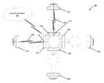
- FIG. 1is a schematic diagram of an example radio system that comprises a plurality of collocated radios that are configured to use a shared channel for communication with a plurality of far radios.
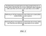
- FIG. 2is a flowchart of an example method for synchronous radio transmission on a shared channel.
- FIGS. 3A-Ccollectively illustrate an example radio for use in accordance with the present technology.
- FIG. 4is another example method for synchronous radio transmission on a shared channel.
- FIG. 5illustrates an exemplary computing device that may be used to implement embodiments according to the present technology.
- the present technologyprovides methods for simultaneous transmission of data on a shared channel using a plurality of collocated radios.
- the radio system 100comprises two or more collocated radios such as radio 105 and radio 110 . These radios are located in proximity to one another such that without the use of the present technology, the radios would interfere with one another when transmitting or receiving.
- the radios 105 and 110are each coupled with far radios over long range wireless links.
- radio 105is couplable with a first far radio 115 over a long range wireless link 120 and radio 110 is couplable with a second far radio 125 over a long range wireless link 130 .
- additional collocated and far radioscan be utilized to practice the present technology, such as radios 135 and 140 and far radios 145 and 150 .
- the radio system 100can comprise a cloud controller 155 that is utilized to control various aspects of the radio system 100 such as channel synchronization and antenna gain adjustment, as will be described in greater detail infra.
- Each of the radios 105 and 110will have an on-axis response and an off-axis response when transmitting and receiving signals.
- the on-axis response for a radiooccurs along a main axis of a radio such as axis X 1 for radio 105 and axis X 2 for radio 110 .
- radio 105will have an on-axis response to signals from the first far radio 115 .
- An off-axis responseis where interference is experienced by a radio due to overlapping signals from other radios.
- radio 105may have an off-axis response due to bleed over from radio 110 or over from the second far radio 125 . For example, if the second far radio 125 antenna gain is too powerful its radiation pattern can partially envelop the radio 105 , interfering with the on-axis signal.
- the present technologyutilizes a set of features that allow the radios 105 and 110 to transmit or receive in synchronization with one another.
- the radios 105 and 110utilize the same channel or frequency.
- a signal-to-noise (SNR) ratiois maintained between the on-axis response and the off-axis response to ensure that the SNR of the radios 105 and 110 are transmitting and/or receiving a high quality signal.
- the present technologyutilizes selective adjustment of the on-axis responses of the radios 105 and 110 to ensure that the on-axis responses are substantially equal to one another.
- radios 105 and 110when combined and optimized allow for the radios 105 and 110 to transmit in synchronization with one another, both in time and on the same channel.
- the radio 105can be placed in alignment with a reference line that extends along axis X 1 .
- the radio 110can be placed in alignment with a reference line that extends along axis X 2 .
- the reference line R 1 and R 2are angularly spaced apart from one another by approximately 90 degrees. The angular spacing of the radios 105 and 110 function to reduce the likelihood that radiation bleed over will occur between the radios 105 and 110 .
- each of the radios 105 and 110comprises an enclosure that possesses side lobe rejection shrouds or foam insulation that reduces the broadcast of off-axis radiation.
- An example radio with enclosureis illustrated and described relative to FIGS. 3A-C .
- the radios 105 and 110may transmit different data from one another, which increases the volume and diversity of data that can be transmitted at the same time.
- collocated radiosmay be grouped together according to a common time reference, such as a time slot. That is, collocated radios may be configured to transmit simultaneously according to a schedule.
- the spacing of the radios 105 and 110 , as well as careful timing of the data transmissionsallow for simultaneous transmission of different data using the same channel. It will be understood that using radios 105 and 110 having adequate side lobe radiation rejection may enhance the efficacy of data transmissions of the radio system 100 .
- the radio system 100may implement signal synchronization using, for example, GPS time references.
- the radio system 100may obtain GPS time references from a GPS satellite system (not shown).
- a GPS receivermay be associated with each transmitter and receiver individually and may be utilized to obtain GPS time references from the GPS satellite system.
- integrating the GPS receiver within a device itselfadvantageously eliminates time deltas present in systems that require the transmission of GPS information from a GPS receiver to a desired device. That is, wired or wireless transmission of GPS information between a main GPS receiver and a plurality of devices introduces timing delays.
- each radio 105 and 110is provided with a GPS module that receives GPS information such as time and location data.
- GPS informationcan be utilized to synchronize the radios 105 and 110 in their broadcast times.
- the radios 105 and 110can be selectively controlled to broadcast on a selected channel by, for example, a human installer or technician. In another example, the radios 105 and 110 are selectively controlled by the cloud controller 155 over a network.
- radio 105is provided with a GPS module. Radio 105 shares its GPS information with radio 110 over a wired connection such as an Ethernet connection.
- the radios 105 and 110are channel and time synchronized with one another over a network connection.
- the radios 105 and 110can receive channel and/or time parameters over a network connection from local WiFi network.
- the difference in proximitycan cause the radio 105 to have an on-axis response that is greater than the on-axis response of the radio 110 . This is due to signal power reduction due to free space loss that is greater for radio 110 than radio 105 .
- a transmission for the two kilometer distancemay be 6 dBm quieter than a transmission for the one kilometer distance.
- the transmitter or radio for the one kilometer distancemay be backed down by 6 dBm.
- Another method of implementing power back-offmay be a closed-loop method. This method may have the receiver radio communicate the current signal strength to the transmitter radio. Depending on whether the signal strength is higher or lower than the target, the transmitter radio then knows how many decibels to reduce or increase its power level to achieve the target receive signal strength.
- the radios 105 and 110can have their transmit and/or receive antenna gains selectively adjusted to compensate for disparate signal strengths in their on-axis responses. Selective adjustment of transmit or receive antenna gain can be accomplished using a microprocessor that executes gain adjustment logic stored in memory, in accordance with the examples provided above.
- the present technologycan be utilized to synchronize collocated radios owned by different entities, such as ISPs.
- entitiessuch as ISPs.
- multiple radios operated by a plurality of entitiescan be collocated on public or private structures such as buildings or towers. Since these entities typically do not strategically plan their broadcast schedules, interference frequently occurs between these radios.
- the cloud controller 155is configured to monitor interference between collocated radios by determining radios that are not operating in synchronization with one another. This lack of synchronization can itself be indicative of interference.
- a spectral scannermay be utilized at the collocated radio location to sense asynchronous broadcast periods.
- the entitiescan provide the cloud controller 155 with access to broadcast schedules for their radios.
- the cloud controller 155can identify these out of synch radios and inform the owners of these radios that synchronization may improve network performance. The cloud controller 155 can then synchronize the collocated radios in their channel usage and their operational timing using the aforementioned features.
- the radio system 100comprises additional collocated radios 135 and 140 .
- the radio system 100allows for a synchronized timing scheme may result in each transceiver may be assigned a timing.
- radios 105 and 110may be assigned a timing A and radios 135 and 140 may be assigned a timing B.
- the units with timing Atransmit at the same time, while timing B units receive during this time.
- timing B unitsare transmitting, timing A units are receiving.
- access pointsthat typically broadcast an SSID, and there are clients/stations that associate with the access points.
- access pointsmay be allowed to be either timing A, or timing B units, and similarly allow clients/stations to be either. This is necessary, because all radios per tower or site must have the same timing gender to avoid interference, and yet not all radios per location are necessarily access points or clients/stations exclusively.
- each radiomay be configured to execute a configuration cycle in order to communicatively couple itself with the radio system 100 .
- the configuration cyclemay include execution of a site survey, where the device determines whether a radio is a transmitter or receiver. Because the radios used herein may operate as a transmitter or a receiver, the radio may initially determine whether it has been purposed as a transmitter or a receiver.
- the radiomay be pre-loaded (executable instructions stored in memory) with an augmented service identifier (SSID) information set.
- SSIDaugmented service identifier
- the augmented SSID information set of the present technologymay additionally include location information (e.g., latitude and longitude) as well as a mode of operation and security type (e.g., security protocol used by the radio).
- location informatione.g., latitude and longitude
- security typee.g., security protocol used by the radio.
- the location informationmay allow the radio to deduce or determine additional radios with which the radio has been collocated. If the radio is replacing another radio, a mode of operation instruction set may be provided to the replacement radio that informs the radio of its required mode of operation.
- the mode of operationmay inform the radio of its broadcast and/or receiving schedules, as well as channel information, such as the shared channel utilized by the plurality of radios.
- the radiomay, upon power up, enter into scan mode to determine a list of collocated radios, as well as broadcast its own SSID to other collocated radios. The radio may then exit the scan mode and perform a manual rescan, listing for configuration information. The radio may reset configuration details to default or factory settings. In other instances, the configuration details determined by the radio during the scan session may be installed or accepted by the radio.
- the radiomay be configured to broadcast ping signals that are received by, for example, receivers/radios that are not collocated with the radio. Using the time differential between transmission of a ping signal by a radio, relative to receiving of the ping signal by a receiver, an approximate distance between radios may be determined. Again, a GPS counter may track the broadcast and receipt of signals. The radio system may compare the GPS time references associated with the broadcast and received signals to determine distance values.
- each radiomay utilize a media access control (MAC) layer protocol that uses GPS coordinates.
- MACmedia access control
- the latitude and longitude of each transmitter and receiveris shown on a map, which may be displayed via a graphical user interface.
- the site survey data pointsmay be stored in a log file.
- radio system 100 of FIG. 1can be configured to selectively vary transmit and receive bandwidth.
- the radio system 100 of FIG. 1in operation may provide in the 80 megahertz spectrum, 802.11ac wireless data transmission having TCP/IP bandwidth of approximately 4.8 gigabits per second (Gbps), which includes 2.4 Gbps of upload bandwidth and 2.4 Gbps of download bandwidth, assuming the transmit/receive workload of the radio system 100 is split evenly at 50 percent transmit and 50 percent receive.
- TCP/IP bandwidthmay be approximately 1 Gbps to 1.2 Gbps, which includes 500 megabits per second (Mbps) to 600 Mbps of upload bandwidth and 500 Mbps to 600 Mbps of download bandwidth, assuming the transmit/receive workload of the antenna split evenly between 50 percent transmit and 50 percent receive.
- the available bandwidth of the radio system 100may be selectively adjusted such that more bandwidth may be dedicated to download bandwidth.
- the bandwidth splitmay be selectively adjusted such that the download bandwidth is 70 percent of the total bandwidth of the radio system 100 while the upload bandwidth is approximately 30 percent.
- Such selective adjustmentallows for fine tuning of the radio system 100 to service the needs of end users. For example, when end users frequently consume more download bandwidth than upload bandwidth, the download bandwidth may be increased.
- This bandwidth splitmay be automatically varied according to the empirical end user behavior. While the embodiment described provides for wireless data transmission in the 80 MHz spectrum, other embodiments may utilize up to the 160 MHz spectrum, inclusive of the 20 MHz, 40 MHz, or 80 MHz spectrums beneath it.
- FIG. 2is a flowchart of an example method that is executed in accordance with the present technology.
- the methodincludes transmitting signals on a same channel by two or more collocated radios by initially synchronizing 205 transmit and receive time periods of the two or more radios such that the two or more collocated radios transmit at the same time and receive at the same time as one another.
- the radiosare collocated in proximity to one another such that without use of the present technology, the radios would interfere with one another when broadcasting and/or receiving.
- the methodalso includes reducing 210 an off-axis response for each of the two or more radios relative to their on-axis response.
- the reduction in off-axis responsecan occur with the use of side lobe rejecting enclosures or with adequate angular separation between radios.
- the methodincludes balancing 215 the on-axis response for each of the two or more radios such that they are substantially equivalent to one another.
- the steps of the methodneed be executed in any particular order.
- the reduction in off-axis responsemay occur due to physical properties or placement of radios, which can occur prior to channel and time synchronization, as well as on-axis response balancing.
- FIGS. 3A-Ccollectively illustrate an exemplary device 300 .
- FIG. 3Aincludes front and rear perspective views of a device 300 in an assembled configuration.
- the device 300is provided with a dedicated antenna 370 that extends from a back cover 310 of the device 300 .
- FIG. 3Bis an exploded perspective view of the device 300 (e.g., radio).
- the device 300comprises a mounting bracket 305 , a back cover 310 , a gasket 315 , a PCB (printed circuit board) assembly 320 , a dish 325 , a cylindrical dielectric plate 345 , a reflector 355 , and a radome 360 .
- a mounting bracket 305e.g., radio
- the device 300comprises a mounting bracket 305 , a back cover 310 , a gasket 315 , a PCB (printed circuit board) assembly 320 , a dish 325 , a cylindrical dielectric plate 345 , a reflector 355 , and a radome 360 .
- PCBprinted circuit board
- the dish of the present technologyis manufactured monolithically as one piece. That is, the dish antenna (also referenced as “dish”) 325 includes a parabolic circular reflector 325 A that is bounded by the side lobe shield 330 to form the front cavity 335 , and rear cavity 375 . All these components are manufactured as a single device, as opposed to technologies where dishes are formed from separate components that are assembled in the field. Further, many dishes are an amalgamation of parts from a plurality of manufacturers, which can lead to physical incompatibility and on the fly modification in the field.
- the monolithic dishprovides advantages such as reduced manufacturing cost, since the dish can be manufactured in a single process.
- the dishcan be manufactured using injection molding, or any other similar process that is capable of producing a dish with the physical features as those illustrated in the drawings of the disclosure.
- the PCB assembly 320can be housed within the rear cavity 375 . This places the PCB assembly 320 and waveguide 350 (discussed in greater detail below) in very close proximity to the parabolic circular reflector 325 A, which reduces or eliminates signal attenuation of signals produced by the PCB assembly 320 that are directed through the waveguide 350 that would be present if the PCB assembly 320 and/or waveguide 350 are not located proximate the parabolic circular reflector 325 A.
- the mounting bracket 305that allows the device 300 to be pivotally coupled to a mounting surface, such as a tower (not shown).
- a mounting surfacesuch as a tower (not shown).
- the ability of the device 300 to be pivotally connected to a mounting surfaceallows for an azimuth angle to be established, as would be known to one of ordinary skill in the art with the present disclosure before them. While the mounting bracket 305 has been described, the device 300 couples with a structure using any one or more of a number of mechanisms that would be apparent to one of ordinary skill in the art with the present disclosure before them.
- the mounting bracket 305couples with a back cover via a plurality of fasteners.
- the mounting bracket 305couples to the back cover 310 using fasteners.
- the mounting bracket 305couples with a set of pole clamps 390 A that allow the device 300 to be clamped to a pole or other similar structure.
- the device 300also comprises a dish antenna 325 that is formed so as to include a rear cavity 375 (see FIG. 3C ) and a front cavity 335 .
- a PCB assembly 320is disposed at least partially within the rear cavity of the dish.
- the PCB assembly 320includes any circuits needed to operate the device 300 .
- the dish antenna 325is a parabolic circular reflector 325 A that is bounded by the side lobe shield 330 to form the front cavity 335 .
- the front cavityextends forwardly from the dish.
- the shape of the parabolic reflectordepends upon the desired radiation pattern for the device 300 .
- the exact shape and size of the parabolic circular reflectorvaries according to design and implementational requirements.
- a sealsuch as a gasket 315 , is disposed between the outer peripheral edge of the rear cavity 375 and the back cover 310 to sealingly protect the PCB assembly 320 from contamination.
- the PCB assembly 320also includes a PCB heat spreader 385 or other means for transferring heat generated by the PCB assembly 320 to the ambient environment such as fans and so forth.
- the dish 325includes a side lobe shield 330 that extends beyond the outer peripheral edge of the dish 325 .
- the side lobe shield 330is a shroud having a sidewall that forms a ring around the outer peripheral edge of an upper surface of the dish 325 .
- the side lobe shield 330extends from the dish 325 axially along a longitudinal axis X of the device 300 .
- the dish 325in some embodiments, is manufactured as a monolithic or one piece device.
- the dish 325is manufactured from any one or combination of materials that are suitable for use as with an antenna.
- the inner surface of the side lobe shield 330is provided with a metalized coating.
- the upper surface 325 B of the parabolic circular reflector 325 Aalso includes a metalized coating.
- at least a portion of the inner surface of the side lobe shieldis augmented with a metallic coating and/or a microwave absorbing material (also known as the “material”) 340 , such as a foam or other electrically insulating material that is coated along the inner surface of the front cavity 335 of the dish 325 .
- the material 340lines the inner portion of the side lobe shield 330 .
- the upper surface 325 Bis generally circular and parabolic in shape, which aids in directing radiation along the longitudinal axis X. Again, the shape of the dish 325 functions to reduce emissions of side lobe radiation.
- the dish 325has an annular shaped mounting ring 380 that is configured to receive the wave guide 350 .
- the microwave absorbing material 340is shown as being disposed within the front cavity 335 in FIG. 3B , but can also be applied or sprayed to the inner surface of the side lobe shield 330 .
- the microwave absorbing material 340is integrated into the side lobe shield 330 itself. That is, the side lobe shield 330 is manufactured as a layered or composite.
- the side lobe shield 330comprises a substrate of a metallic material that has a layer of microwave absorbing material applied thereto. Specifically, the absorbing material would be applied to a surface of the side lobe shield that is proximate the wave guide 350 of the device.
- a metalized coatingis applied to the entire upper surface of the dish 325 and the inner sidewall of the side lobe shield 330 .
- the side lobe shield 330functions to direct the signals reflected by the dish surface in a more uniform and directed pattern.
- the side lobe shield 330reduces side lobe radiation which is transmitted from and/or received by the device 300 .
- the device 300reduces an amount of signals (e.g., radiation) which are received by the device 300 such as those transmitted by adjacent transmitters.
- the side lobe shield 330 of the device 300also reduces an amount of microwave signals transmitted via side lobe projection by the device 300 .
- the device 300reduces both the transmission and reception of deleterious side lobe signals.
- the device 300also comprises a wave guide 350 that is communicatively coupled with the PCB assembly 320 .
- a cylindrical dielectric plate 345couples with the wave guide 350 .
- a reflector 355is associated with the cylindrical dielectric plate 345 .
- the combination of the PCB assembly 320 , wave guide 350 , cylindrical dielectric plate 345 , and reflector 355are collectively referred to as a “radio.”
- a radome cover 360attaches to the side lobe shield 330 to sealingly cover the reflector 355 , cylindrical dielectric plate 345 , and wave guide 350 that are housed within the front cavity 335 .
- the radome 360 , side lobe shield 330 , dish 325 , and back cover 310 of the device 300is constructed from any suitable material such as a plastic, a polymeric material, a resin, a composite material, a natural material, or any other material that would be known to one of ordinary skill in the art.
- the dish 325 and the side lobe shield 330is manufactured as an integral unit.
- the rear cavity 375 of the dish 325is formed to provide a mounting surface for receiving the PCB assembly 320 .
- the rear cavity 375is formed by a sidewall 395 that extends rearwardly from the dish antenna 325 along the longitudinal axis X.
- the sidewall 395extends in an opposing direction from the side lobe shield 330 .
- the dish 325as an integral unit, is manufactured from a plastic material, a polymeric material, a resin, a composite material, or other suitable material that would be known to one of ordinary skill in the art with the present disclosure before them.
- the inner sidewall of the side lobe shield 330 and the upper surface 325 A of the dish 325is metalized while the rear cavity 375 is not metalized.
- the side lobe shield 330is provided with a microwave insulating material.
- the dish antenna 325comprises a series of fins 390 .
- These fins 390may extend from the rear cavity 375 upwardly to the edge of the side lobe shield 330 . More specifically, the series of fins extends upwardly from the sidewall of the rear cavity along an underside of the parabolic circular reflector or dish 325 .
- FIG. 4is a flowchart of another example method of the present technology. To be sure, the method involves communication synchronization between two or more radios. As mentioned herein, the two or more radios have angular separation or physical characteristics that optimize their on-axis responses.
- the methodcan include an optional step of detecting 405 interference between the radios.
- the methodcan also omit step 405 in some embodiments.
- the methodincludes selecting 410 a shared channel for the two or more radios.
- the cloud controllercan select 80 MHz as the shared frequency/channel.
- the methodincludes synchronizing 415 transmit and receive time periods of the two or more radios such that the two or more collocated radios transmit at the same time and receive at the same time as one another on the shared channel. As mentioned above, this could be accomplished using GPS modules in each of the radios.
- the methodincludes balancing 420 an on-axis response for each of the two or more radios such that they are substantially equivalent to one another.
- the combination of on-axis response balancing with off-axis response reduction to produce adequate signal to noise ratio at each of the radios, as well as time and channel uniformityallow for synchronized transmission of data by two or more collocated radios.
- FIG. 5is a diagrammatic representation of an example machine in the form of a computer system 1 , within which a set of instructions for causing the machine to perform any one or more of the methodologies discussed herein may be executed.
- the machineoperates as a standalone device or may be connected (e.g., networked) to other machines.
- the machinemay operate in the capacity of a server or a client machine in a server-client network environment, or as a peer machine in a peer-to-peer (or distributed) network environment.
- the machinemay be a radio, a base station, a personal computer (PC), a web appliance, a network router, switch or bridge, or any machine capable of executing a set of instructions (sequential or otherwise) that specify actions to be taken by that machine.
- PCpersonal computer
- web appliancea network router, switch or bridge
- any machinecapable of executing a set of instructions (sequential or otherwise) that specify actions to be taken by that machine.
- the term “machine”shall also be taken to include any collection of machines that individually or jointly execute a set (or multiple sets) of instructions to perform any one or more of the methodologies discussed herein.
- the example computer system 1includes a processor or multiple processors 5 (e.g., a central processing unit (CPU), a graphics processing unit (GPU), or both), and a main memory 10 and static memory 15 , which communicate with each other via a bus 20 .
- the computer system 1may further include a video display 35 (e.g., a liquid crystal display (LCD)).
- the computer system 1may also include an alpha-numeric input device(s) 30 (e.g., a keyboard), a cursor control device (e.g., a mouse), a voice recognition or biometric verification unit (not shown), a drive unit 37 (also referred to as disk drive unit), a signal generation device 40 (e.g., a speaker), and a network interface device 45 .
- the computer system 1may further include a data encryption module (not shown) to encrypt data.
- the disk drive unit 37includes a computer or machine-readable medium 50 on which is stored one or more sets of instructions and data structures (e.g., instructions 55 ) embodying or utilizing any one or more of the methodologies or functions described herein.
- the instructions 55may also reside, completely or at least partially, within the main memory 10 and/or within the processors 5 during execution thereof by the computer system 1 .
- the main memory 10 and the processors 5may also constitute machine-readable media.
- the instructions 55may further be transmitted or received over a network via the network interface device 45 utilizing any one of a number of well-known transfer protocols (e.g., Hyper Text Transfer Protocol (HTTP)).
- HTTPHyper Text Transfer Protocol
- the machine-readable medium 50is shown in an example embodiment to be a single medium, the term “computer-readable medium” should be taken to include a single medium or multiple media (e.g., a centralized or distributed database and/or associated caches and servers) that store the one or more sets of instructions.
- computer-readable mediumshall also be taken to include any medium that is capable of storing, encoding, or carrying a set of instructions for execution by the machine and that causes the machine to perform any one or more of the methodologies of the present application, or that is capable of storing, encoding, or carrying data structures utilized by or associated with such a set of instructions.
- the term “computer-readable medium”shall accordingly be taken to include, but not be limited to, solid-state memories, optical and magnetic media, and carrier wave signals. Such media may also include, without limitation, hard disks, floppy disks, flash memory cards, digital video disks, random access memory (RAM), read only memory (ROM), and the like.
- RAMrandom access memory
- ROMread only memory
- the example embodiments described hereinmay be implemented in an operating environment comprising software installed on a computer, in hardware, or in a combination of software and hardware.
- the Internet servicemay be configured to provide Internet access to one or more computing devices that are coupled to the Internet service, and that the computing devices may include one or more processors, buses, memory devices, display devices, input/output devices, and the like.
- the Internet servicemay be coupled to one or more databases, repositories, servers, and the like, which may be utilized in order to implement any of the embodiments of the disclosure as described herein.
- These computer program instructionsmay also be stored in a computer readable medium that can direct a computer, other programmable data processing apparatus, or other devices to function in a particular manner, such that the instructions stored in the computer readable medium produce an article of manufacture including instructions which implement the function/act specified in the flowchart and/or block diagram block or blocks.
- the computer program instructionsmay also be loaded onto a computer, other programmable data processing apparatus, or other devices to cause a series of operational steps to be performed on the computer, other programmable apparatus or other devices to produce a computer implemented process such that the instructions which execute on the computer or other programmable apparatus provide processes for implementing the functions/acts specified in the flowchart and/or block diagram block or blocks.
- each block in the flowchart or block diagramsmay represent a module, segment, or portion of code, which comprises one or more executable instructions for implementing the specified logical function(s).
- the functions noted in the blockmay occur out of the order noted in the figures. For example, two blocks shown in succession may, in fact, be executed substantially concurrently, or the blocks may sometimes be executed in the reverse order, depending upon the functionality involved.
- a hyphenated term(e.g., “on-demand”) may be occasionally interchangeably used with its non-hyphenated version (e.g., “on demand”)
- a capitalized entrye.g., “Software”
- a non-capitalized versione.g., “software”
- a plural termmay be indicated with or without an apostrophe (e.g., PE's or PEs)
- an italicized terme.g., “N+1” may be interchangeably used with its non-italicized version (e.g., “N+1”).
- Such occasional interchangeable usesshall not be considered inconsistent with each other.
- a “means for”may be expressed herein in terms of a structure, such as a processor, a memory, an I/O device such as a camera, or combinations thereof.
- the “means for”may include an algorithm that is descriptive of a function or method step, while in yet other embodiments the “means for” is expressed in terms of a mathematical formula, prose, or as a flow chart or signal diagram.
Landscapes
- Engineering & Computer Science (AREA)
- Computer Networks & Wireless Communication (AREA)
- Signal Processing (AREA)
- Mobile Radio Communication Systems (AREA)
Abstract
Description
Claims (20)
Priority Applications (5)
| Application Number | Priority Date | Filing Date | Title |
|---|---|---|---|
| US14/657,942US9998246B2 (en) | 2014-03-13 | 2015-03-13 | Simultaneous transmission on shared channel |
| US15/955,723US10447417B2 (en) | 2014-03-13 | 2018-04-18 | Synchronized transmission on shared channel |
| US16/591,589US11888589B2 (en) | 2014-03-13 | 2019-10-02 | Synchronized transmission on shared channel |
| US18/528,595US12206490B2 (en) | 2014-03-13 | 2023-12-04 | Systems and methods of communication synchronization between two or more radios |
| US18/927,684US20250055588A1 (en) | 2014-03-13 | 2024-10-25 | Systems and Methods of Communication Synchronization Between Two or More Radios on a Shared Channel |
Applications Claiming Priority (2)
| Application Number | Priority Date | Filing Date | Title |
|---|---|---|---|
| US201461952597P | 2014-03-13 | 2014-03-13 | |
| US14/657,942US9998246B2 (en) | 2014-03-13 | 2015-03-13 | Simultaneous transmission on shared channel |
Related Child Applications (1)
| Application Number | Title | Priority Date | Filing Date |
|---|---|---|---|
| US15/955,723ContinuationUS10447417B2 (en) | 2014-03-13 | 2018-04-18 | Synchronized transmission on shared channel |
Publications (2)
| Publication Number | Publication Date |
|---|---|
| US20150263816A1 US20150263816A1 (en) | 2015-09-17 |
| US9998246B2true US9998246B2 (en) | 2018-06-12 |
Family
ID=54070166
Family Applications (5)
| Application Number | Title | Priority Date | Filing Date |
|---|---|---|---|
| US14/657,942ActiveUS9998246B2 (en) | 2014-03-13 | 2015-03-13 | Simultaneous transmission on shared channel |
| US15/955,723ActiveUS10447417B2 (en) | 2014-03-13 | 2018-04-18 | Synchronized transmission on shared channel |
| US16/591,589Active2037-09-30US11888589B2 (en) | 2014-03-13 | 2019-10-02 | Synchronized transmission on shared channel |
| US18/528,595ActiveUS12206490B2 (en) | 2014-03-13 | 2023-12-04 | Systems and methods of communication synchronization between two or more radios |
| US18/927,684PendingUS20250055588A1 (en) | 2014-03-13 | 2024-10-25 | Systems and Methods of Communication Synchronization Between Two or More Radios on a Shared Channel |
Family Applications After (4)
| Application Number | Title | Priority Date | Filing Date |
|---|---|---|---|
| US15/955,723ActiveUS10447417B2 (en) | 2014-03-13 | 2018-04-18 | Synchronized transmission on shared channel |
| US16/591,589Active2037-09-30US11888589B2 (en) | 2014-03-13 | 2019-10-02 | Synchronized transmission on shared channel |
| US18/528,595ActiveUS12206490B2 (en) | 2014-03-13 | 2023-12-04 | Systems and methods of communication synchronization between two or more radios |
| US18/927,684PendingUS20250055588A1 (en) | 2014-03-13 | 2024-10-25 | Systems and Methods of Communication Synchronization Between Two or More Radios on a Shared Channel |
Country Status (1)
| Country | Link |
|---|---|
| US (5) | US9998246B2 (en) |
Cited By (16)
| Publication number | Priority date | Publication date | Assignee | Title |
|---|---|---|---|---|
| US10090943B2 (en) | 2014-03-05 | 2018-10-02 | Mimosa Networks, Inc. | System and method for aligning a radio using an automated audio guide |
| US10096933B2 (en) | 2013-03-06 | 2018-10-09 | Mimosa Networks, Inc. | Waterproof apparatus for cables and cable interfaces |
| US10117114B2 (en) | 2013-03-08 | 2018-10-30 | Mimosa Networks, Inc. | System and method for dual-band backhaul radio |
| US10200925B2 (en) | 2013-02-19 | 2019-02-05 | Mimosa Networks, Inc. | Systems and methods for directing mobile device connectivity |
| US10425944B2 (en) | 2013-02-19 | 2019-09-24 | Mimosa Networks, Inc. | WiFi management interface for microwave radio and reset to factory defaults |
| US10447417B2 (en) | 2014-03-13 | 2019-10-15 | Mimosa Networks, Inc. | Synchronized transmission on shared channel |
| US10511074B2 (en) | 2018-01-05 | 2019-12-17 | Mimosa Networks, Inc. | Higher signal isolation solutions for printed circuit board mounted antenna and waveguide interface |
| US10616903B2 (en) | 2014-01-24 | 2020-04-07 | Mimosa Networks, Inc. | Channel optimization in half duplex communications systems |
| US10742275B2 (en) | 2013-03-07 | 2020-08-11 | Mimosa Networks, Inc. | Quad-sector antenna using circular polarization |
| US10749263B2 (en) | 2016-01-11 | 2020-08-18 | Mimosa Networks, Inc. | Printed circuit board mounted antenna and waveguide interface |
| US10785608B2 (en) | 2013-05-30 | 2020-09-22 | Mimosa Networks, Inc. | Wireless access points providing hybrid 802.11 and scheduled priority access communications |
| US10938110B2 (en) | 2013-06-28 | 2021-03-02 | Mimosa Networks, Inc. | Ellipticity reduction in circularly polarized array antennas |
| US10958332B2 (en) | 2014-09-08 | 2021-03-23 | Mimosa Networks, Inc. | Wi-Fi hotspot repeater |
| US11069986B2 (en) | 2018-03-02 | 2021-07-20 | Airspan Ip Holdco Llc | Omni-directional orthogonally-polarized antenna system for MIMO applications |
| US11251539B2 (en) | 2016-07-29 | 2022-02-15 | Airspan Ip Holdco Llc | Multi-band access point antenna array |
| US11289821B2 (en) | 2018-09-11 | 2022-03-29 | Air Span Ip Holdco Llc | Sector antenna systems and methods for providing high gain and high side-lobe rejection |
Families Citing this family (8)
| Publication number | Priority date | Publication date | Assignee | Title |
|---|---|---|---|---|
| US9362629B2 (en) | 2013-03-06 | 2016-06-07 | Mimosa Networks, Inc. | Enclosure for radio, parabolic dish antenna, and side lobe shields |
| USD752566S1 (en) | 2014-09-12 | 2016-03-29 | Mimosa Networks, Inc. | Wireless repeater |
| US9787354B2 (en) | 2014-10-29 | 2017-10-10 | FreeWave Technologies, Inc. | Pre-distortion of receive signal for interference mitigation in broadband transceivers |
| US10033511B2 (en)* | 2014-10-29 | 2018-07-24 | FreeWave Technologies, Inc. | Synchronization of co-located radios in a dynamic time division duplex system for interference mitigation |
| US10149263B2 (en) | 2014-10-29 | 2018-12-04 | FreeWave Technologies, Inc. | Techniques for transmitting/receiving portions of received signal to identify preamble portion and to determine signal-distorting characteristics |
| US9819446B2 (en) | 2014-10-29 | 2017-11-14 | FreeWave Technologies, Inc. | Dynamic and flexible channel selection in a wireless communication system |
| US10848537B2 (en)* | 2016-11-15 | 2020-11-24 | Google Llc | Leveraging aggregated network statistics for enhancing quality and user experience for live video streaming from mobile devices |
| WO2025137832A1 (en)* | 2023-12-25 | 2025-07-03 | Intel Corporation | Methods and devices for selecting a radio communication network |
Citations (242)
| Publication number | Priority date | Publication date | Assignee | Title |
|---|---|---|---|---|
| US2735993A (en) | 1956-02-21 | humphrey | ||
| US3182129A (en) | 1965-05-04 | Clark etalelectronic stethoscope | ||
| US4188633A (en) | 1978-01-26 | 1980-02-12 | Hazeltine Corporation | Phased array antenna with reduced phase quantization errors |
| US4402566A (en) | 1981-10-13 | 1983-09-06 | International Telephone & Telegraph Corporation | Field repairable electrical connector |
| USD273111S (en) | 1981-02-09 | 1984-03-20 | Canon Kabushiki Kaisha | Combined data input terminal and acoustic coupler |
| US4543579A (en) | 1983-03-29 | 1985-09-24 | Radio Research Laboratories, Ministry Of Posts And Telecommunications | Circular polarization antenna |
| US4626863A (en) | 1983-09-12 | 1986-12-02 | Andrew Corporation | Low side lobe Gregorian antenna |
| US4835538A (en) | 1987-01-15 | 1989-05-30 | Ball Corporation | Three resonator parasitically coupled microstrip antenna array element |
| US4866451A (en) | 1984-06-25 | 1989-09-12 | Communications Satellite Corporation | Broadband circular polarization arrangement for microstrip array antenna |
| US4893288A (en) | 1986-12-03 | 1990-01-09 | Deutsche Thomson-Brandt Gmbh | Audible antenna alignment apparatus |
| US4903033A (en) | 1988-04-01 | 1990-02-20 | Ford Aerospace Corporation | Planar dual polarization antenna |
| US4986764A (en) | 1989-10-31 | 1991-01-22 | Amp Incorporated | High voltage lead assembly and connector |
| US5015195A (en) | 1990-03-13 | 1991-05-14 | Thomas & Betts Corporation | Plug and socket electrical connection assembly |
| US5226837A (en) | 1990-11-16 | 1993-07-13 | Raychem Corporation | Environmentally protected connection |
| US5231406A (en) | 1991-04-05 | 1993-07-27 | Ball Corporation | Broadband circular polarization satellite antenna |
| USD346598S (en) | 1992-04-28 | 1994-05-03 | Coherent Communications Systems Corporation | Transceiver module for a table-top teleconferencing system |
| USD355416S (en) | 1994-02-14 | 1995-02-14 | Coherent Communications Systems Corporation | Transceiver module for a table-top teleconferencing system |
| US5389941A (en) | 1992-02-28 | 1995-02-14 | Hughes Aircraft Company | Data link antenna system |
| US5491833A (en) | 1993-12-27 | 1996-02-13 | Nec Corporation | Mobile radio communication system having radio zones of sector configurations and antenna selecting method employed therein |
| US5513380A (en) | 1992-09-23 | 1996-04-30 | Siemens Aktiengesellschaft | Mobile speed dependent handover techniques in hierarchical mobile radio networks |
| US5561434A (en) | 1993-06-11 | 1996-10-01 | Nec Corporation | Dual band phased array antenna apparatus having compact hardware |
| USD375501S (en) | 1994-01-28 | 1996-11-12 | American Phone Products, Inc. | Cup receptacle for telephone hand set |
| US5580264A (en) | 1994-08-09 | 1996-12-03 | Sumitomo Wiring Systems, Ltd. | Waterproofed connector |
| US5684495A (en) | 1995-08-30 | 1997-11-04 | Andrew Corporation | Microwave transition using dielectric waveguides |
| USD389575S (en) | 1996-10-22 | 1998-01-20 | Grasfield James A | Chestpiece of a stethoscope |
| US5724666A (en) | 1994-03-24 | 1998-03-03 | Ericsson Inc. | Polarization diversity phased array cellular base station and associated methods |
| US5742911A (en) | 1992-10-03 | 1998-04-21 | Motorola, Inc. | Sectorized cellular radio base station antenna |
| US5746611A (en) | 1996-07-15 | 1998-05-05 | The Whitaker Corporation | Electrical connector seal cap assembly |
| US6014372A (en) | 1997-12-08 | 2000-01-11 | Lockheed Martin Corp. | Antenna beam congruency system for spacecraft cellular communications system |
| US6067053A (en) | 1995-12-14 | 2000-05-23 | Ems Technologies, Inc. | Dual polarized array antenna |
| US6137449A (en) | 1996-09-26 | 2000-10-24 | Kildal; Per-Simon | Reflector antenna with a self-supported feed |
| US6140962A (en) | 1998-04-29 | 2000-10-31 | Hollandse Signaalapparaten B.V. | Antenna system |
| US6176739B1 (en) | 1997-02-20 | 2001-01-23 | The Whitaker Corporation | Sealed electrical conductor assembly |
| US6216266B1 (en) | 1999-10-28 | 2001-04-10 | Hughes Electronics Corporation | Remote control signal level meter |
| US6304762B1 (en) | 1996-12-23 | 2001-10-16 | Texas Instruments Incorporated | Point to multipoint communication system with subsectored upstream antennas |
| US20010033600A1 (en) | 2000-02-28 | 2001-10-25 | Golden Bridge Technology Inc. | Sectorized smart antenna system and method |
| USD455735S1 (en) | 1999-12-30 | 2002-04-16 | Telaxis Communications Corporation | Subscriber premises transceiver for a local multi-point distribution service |
| US6421538B1 (en) | 1993-12-22 | 2002-07-16 | Nokia Mobile Phones, Limited | Multi-mode radio telephone with velocity sensing mode selection |
| US20020102948A1 (en) | 2000-09-14 | 2002-08-01 | Stanwood Kenneth L. | System and method for wireless communication in a frequency division duplexing region |
| US20020159434A1 (en) | 2001-02-12 | 2002-10-31 | Eleven Engineering Inc. | Multipoint short range radio frequency system |
| US20030013452A1 (en) | 2001-07-13 | 2003-01-16 | Koninklijke Philips Electronics N.V. | Hierarchical cellular radio communication system |
| US20030027577A1 (en) | 2001-08-06 | 2003-02-06 | Metric Systems, Inc. | Wireless communication system control apparatus and method |
| US20030169763A1 (en) | 2002-03-07 | 2003-09-11 | Sunghyun Choi | Coexistence of stations capable of different modulation schemes in a wireless local area network |
| US20030224741A1 (en) | 2002-04-22 | 2003-12-04 | Sugar Gary L. | System and method for classifying signals occuring in a frequency band |
| US20030222831A1 (en) | 2002-05-31 | 2003-12-04 | Brian Dunlap | Three-dimensional spatial division multiplexing access (3D-SDMA) antenna system |
| US20040002357A1 (en)* | 2002-06-25 | 2004-01-01 | Mathilde Benveniste | Directional antennas and wireless channel access |
| US20040029549A1 (en) | 2002-08-09 | 2004-02-12 | Fikart Josef Ludvik | Downconverter for the combined reception of linear and circular polarization signals from collocated satellites |
| US6716063B1 (en) | 2000-02-28 | 2004-04-06 | Pgs Exploration (Us), Inc. | Electrical cable insert |
| US6754511B1 (en) | 2000-02-04 | 2004-06-22 | Harris Corporation | Linear signal separation using polarization diversity |
| US20040120277A1 (en) | 2002-11-18 | 2004-06-24 | Holur Balaji S. | Method and system for service portability across disjoint wireless networks |
| US20040196813A1 (en) | 2003-04-07 | 2004-10-07 | Yoram Ofek | Multi-sector antenna apparatus |
| US20040196812A1 (en) | 2003-04-07 | 2004-10-07 | Instant802 Networks Inc. | Multi-band access point with shared processor |
| US20040242274A1 (en) | 2003-05-30 | 2004-12-02 | Corbett Christopher J. | Using directional antennas to mitigate the effects of interference in wireless networks |
| US20040240376A1 (en) | 2003-05-30 | 2004-12-02 | Agency For Science, Technology And Research | Method for reducing channel estimation error in an OFDM system |
| US6847653B1 (en) | 1999-11-09 | 2005-01-25 | Interwave Communications International, Ltd. | Protocol for voice and data priority virtual channels in a wireless local area networking system |
| US20050032479A1 (en) | 2003-07-28 | 2005-02-10 | Miller Karl A. | Signal classification methods for scanning receiver and other applications |
| USD501848S1 (en) | 2003-07-14 | 2005-02-15 | Sony Corporation | Transmitter |
| US20050058111A1 (en) | 2003-09-15 | 2005-03-17 | Pai-Fu Hung | WLAN device having smart antenna system |
| US6877277B2 (en) | 2000-12-10 | 2005-04-12 | Tiefenbach Bergbautechnik Gmbh | Coupling for explosion-proof connection of two electric line ends |
| US20050124294A1 (en) | 2003-11-17 | 2005-06-09 | Conextant Systems, Inc. | Wireless access point simultaneously supporting basic service sets on multiple channels |
| US20050143014A1 (en)* | 2003-12-29 | 2005-06-30 | Intel Corporation | Antenna subsystem calibration apparatus and methods in spatial-division multiple-access systems |
| US20050195758A1 (en) | 2004-03-05 | 2005-09-08 | Interdigital Technology Corporation | Full duplex communication system using disjoint spectral blocks |
| US20050227625A1 (en) | 2004-03-25 | 2005-10-13 | Diener Neil R | User interface and time-shifted presentation of data in a system that monitors activity in a shared radio frequency band |
| US6962445B2 (en) | 2003-09-08 | 2005-11-08 | Adc Telecommunications, Inc. | Ruggedized fiber optic connection |
| US20050254442A1 (en) | 2004-05-13 | 2005-11-17 | Widefi, Inc. | Non-frequency translating repeater with detection and media access control |
| US20050271056A1 (en) | 2004-05-17 | 2005-12-08 | Matsushita Electronic Industrial Co., Ltd | Packet generation method, communication method, packet processing method and data structure |
| US20060072518A1 (en) | 2000-07-10 | 2006-04-06 | Interdigital Technology Corporation | Code power measurement for dynamic channel allocation |
| US20060099940A1 (en) | 2004-11-10 | 2006-05-11 | Pfleging Gerald W | Method for changing the status of a mobile apparatus |
| US20060098592A1 (en) | 2002-12-16 | 2006-05-11 | Widefi, Inc. | Wireless network repeater |
| US20060132359A1 (en) | 2004-12-22 | 2006-06-22 | Tatung Co., Ltd. | Circularly polarized array antenna |
| US20060132602A1 (en) | 2003-06-12 | 2006-06-22 | Denso Corporation | Image server, image acquisition device, and image display terminal |
| US7075492B1 (en)* | 2005-04-18 | 2006-07-11 | Victory Microwave Corporation | High performance reflector antenna system and feed structure |
| US20060172578A1 (en) | 2005-02-03 | 2006-08-03 | Pacific Wireless Manufacturing, Inc. | Low-cost weatherproof cable feedthrough |
| US20060187952A1 (en) | 2005-02-18 | 2006-08-24 | Avaya Technology Corp. | Methods and systems for providing priority access to 802.11 endpoints using DCF protocol |
| US20060211430A1 (en) | 2005-03-17 | 2006-09-21 | Persico Charles J | GPS position tracking method with variable updating rate for power conservation |
| USD533899S1 (en) | 2003-09-18 | 2006-12-19 | Riso Kagaku Corporation | Hub for a printing paper roll |
| US20070001910A1 (en) | 2003-12-18 | 2007-01-04 | Fujitsu Limited | Antenna device, radio-wave receiver and radio-wave transmitter |
| US20070019664A1 (en) | 2000-11-03 | 2007-01-25 | At&T Corp. | Tiered contention multiple access (TCMA): a method for priority-based shared channel access |
| US7173570B1 (en) | 2004-07-12 | 2007-02-06 | Wensink Jan B | Cell phone tower antenna tilt and heading control |
| US20070035463A1 (en) | 2005-06-03 | 2007-02-15 | Sony Corporation | Antenna device, wireless communication apparatus using the same, and control method of controlling wireless communication apparatus |
| US20070060158A1 (en) | 2005-02-04 | 2007-03-15 | Toshiba American Research, Inc. | Channel partitioning forwireless local area networks |
| US7193562B2 (en) | 2004-11-22 | 2007-03-20 | Ruckus Wireless, Inc. | Circuit board having a peripheral antenna apparatus with selectable antenna elements |
| US7212163B2 (en) | 2004-02-11 | 2007-05-01 | Sony Deutschland Gmbh | Circular polarized array antenna |
| EP1384285B1 (en) | 2001-04-11 | 2007-06-13 | Kyocera Wireless Corp. | Ferroelectric antenna and method for tuning same |
| US20070132643A1 (en) | 2005-12-14 | 2007-06-14 | Harris Corporation | Dual polarization antenna array with inter-element coupling and associated methods |
| US7245265B2 (en) | 2004-07-20 | 2007-07-17 | Vega Grieshaber Kg | Parabolic antenna of a level measuring instrument and level measuring instrument with a parabolic antenna |
| US20070173199A1 (en) | 2006-01-13 | 2007-07-26 | Amit Sinha | Systems and methods for wireless intrusion detection using spectral analysis |
| US20070173260A1 (en) | 2006-01-23 | 2007-07-26 | Love Robert T | Wireless communication network scheduling |
| US7253783B2 (en) | 2002-09-17 | 2007-08-07 | Ipr Licensing, Inc. | Low cost multiple pattern antenna for use with multiple receiver systems |
| US7264494B2 (en) | 2004-12-06 | 2007-09-04 | Weatherford/Lamb, Inc. | Electrical connector and socket assemblies |
| US20070210974A1 (en) | 2002-09-17 | 2007-09-13 | Chiang Bing A | Low cost multiple pattern antenna for use with multiple receiver systems |
| US20070223701A1 (en) | 2006-01-30 | 2007-09-27 | Motorola, Inc. | Method and apparatus for utilizing multiple group keys for secure communications |
| US20070238482A1 (en) | 2006-03-30 | 2007-10-11 | Giora Rayzman | Device, system and method of coordination among multiple transceivers |
| US7281856B2 (en) | 2005-08-15 | 2007-10-16 | Molex Incorporated | Industrial optical fiber connector assembly |
| US20070255797A1 (en) | 2006-04-28 | 2007-11-01 | Dunn Douglas L | Method for selecting an air interface using an access list on a multi-mode wireless device |
| US7292198B2 (en) | 2004-08-18 | 2007-11-06 | Ruckus Wireless, Inc. | System and method for an omnidirectional planar antenna apparatus with selectable elements |
| US20070268848A1 (en) | 2006-05-18 | 2007-11-22 | Qualcomm Incorporated | Half-duplex communication in a frequency division duplex system |
| US7306485B2 (en) | 2006-03-01 | 2007-12-11 | Hirose Electric Co., Ltd. | Waterproof device |
| US7324057B2 (en) | 2005-09-26 | 2008-01-29 | Gideon Argaman | Low wind load parabolic dish antenna fed by crosspolarized printed dipoles |
| USD566698S1 (en) | 2006-03-03 | 2008-04-15 | Lite-On Technology Corp. | Wireless network device |
| US7362236B2 (en) | 2004-12-06 | 2008-04-22 | Itron, Inc. | Mobile utility data collection system with voice technology, such as for data collection relating to an electric, gas, or water utility |
| US7369095B2 (en) | 2000-06-09 | 2008-05-06 | Thomson Licensing | Source-antennas for transmitting/receiving electromagnetic waves |
| US20080109051A1 (en) | 2006-11-06 | 2008-05-08 | Tim John Splinter | System and method for operating a wireless medical device interrogation network |
| US20080112380A1 (en) | 2006-11-10 | 2008-05-15 | Fischer Matthew J | Serial clear to send (cts) to self (cts2self) messaging procedure |
| US7380984B2 (en) | 2005-03-28 | 2008-06-03 | Tokyo Electron Limited | Process flow thermocouple |
| US20080192707A1 (en) | 2006-06-13 | 2008-08-14 | Texas Instruments Incorporated | Reducing collisions in beamforming wireless systems |
| US20080218418A1 (en) | 2007-03-05 | 2008-09-11 | Gillette Marlin R | Patch antenna including septa for bandwidth conrol |
| US20080242342A1 (en) | 2007-03-26 | 2008-10-02 | Broadcom Corporation | Rf filtering at very high frequencies for substrate communications |
| US7431602B2 (en) | 2005-04-21 | 2008-10-07 | Dsm & T Co., Inc. | Electrical connector |
| US20090046673A1 (en) | 2007-08-17 | 2009-02-19 | Oren Kaidar | Method and apparatus for improved dual channel operation and access point discovery in wireless communication networks |
| US20090052362A1 (en) | 2004-05-12 | 2009-02-26 | Meier Robert C | Power-save apparatus for 802.11 multicast paging applications |
| US7498996B2 (en) | 2004-08-18 | 2009-03-03 | Ruckus Wireless, Inc. | Antennas with polarization diversity |
| US20090075606A1 (en) | 2005-06-24 | 2009-03-19 | Victor Shtrom | Vertical multiple-input multiple-output wireless antennas |
| US7507105B1 (en) | 2007-07-17 | 2009-03-24 | Ventek, Llc | Hazardous area coupler device |
| US7542717B2 (en) | 1995-02-22 | 2009-06-02 | Global Communications, Inc. | Satellite broadcast receiving and distribution system |
| US7581976B2 (en) | 2004-06-02 | 2009-09-01 | Gl Tool & Manufacturing Company Inc. | Bulkhead connector |
| US7586891B1 (en) | 2005-12-08 | 2009-09-08 | The United States Of America As Represented By The Secretary Of The Army | Communication network optimization tool |
| US20090233475A1 (en) | 2008-03-11 | 2009-09-17 | Ametek Scp, Inc. | Waterproof gigabit ethernet connector |
| US20090232026A1 (en) | 2007-05-21 | 2009-09-17 | Arrowspan, Inc. | Multi-radio wireless mesh network solutions |
| US7616959B2 (en) | 2004-07-19 | 2009-11-10 | Rotani, Inc. | Method and apparatus for shaped antenna radiation patterns |
| US20090291690A1 (en) | 2008-05-22 | 2009-11-26 | Ntt Docomo, Inc. | Femtocell Channel Assignment and Power Control for Improved Femtocell Coverage and Efficient Cell Search |
| US20090315792A1 (en) | 2006-08-03 | 2009-12-24 | Norihiro Miyashita | Antenna apparatus utilizing small loop antenna element having munute length and two feeding points |
| US20100029282A1 (en) | 2008-07-31 | 2010-02-04 | Qualcomm Incorporated | Resource partitioning in heterogeneous access point networks |
| US20100046650A1 (en) | 2007-01-12 | 2010-02-25 | Joengren George | Method for Precoding Using a Block Diagonal Matrix |
| US7675473B2 (en) | 2005-10-14 | 2010-03-09 | Vega Grieshaber Kg | Parabolic antenna with rinsing connection |
| US20100067505A1 (en) | 2003-11-10 | 2010-03-18 | Yaron Fein | Performance of a Wireless Communication System |
| US20100085950A1 (en) | 2008-10-07 | 2010-04-08 | Masahiro Sekiya | Wireless communication device and wireless communication method |
| US20100091818A1 (en) | 2008-10-14 | 2010-04-15 | Sen Indranil S | Dynamic channel evaluation in wireless communication device |
| US20100103066A1 (en) | 2004-08-18 | 2010-04-29 | Victor Shtrom | Dual Band Dual Polarization Antenna Array |
| US20100103065A1 (en) | 2004-08-18 | 2010-04-29 | Victor Shtrom | Dual Polarization Antenna with Increased Wireless Coverage |
| US20100136978A1 (en) | 2008-12-03 | 2010-06-03 | Electronics And Telecommunications Research | Method for handoff of portable terminal between heterogeneous wireless networks |
| US20100151877A1 (en) | 2008-12-16 | 2010-06-17 | Seung-Hwan Lee | Smart radio communication system and method of operating the same |
| US20100167719A1 (en) | 2005-06-29 | 2010-07-01 | Koninklijke Philips Electronics N.V. | Method and apparatus for delegating signal quality handover measuring of a user equipment in wireless communication to a neighbouring user equipment |
| US20100171675A1 (en) | 2007-06-06 | 2010-07-08 | Carmen Borja | Dual-polarized radiating element, dual-band dual-polarized antenna assembly and dual-polarized antenna array |
| US20100171665A1 (en) | 2007-05-17 | 2010-07-08 | Omron Corporation | Array antenna |
| US20100189005A1 (en) | 2009-01-27 | 2010-07-29 | Bertani Torquato | Method for automatic selection of a mac protocol for a communication system and related system |
| US20100202613A1 (en) | 2009-01-07 | 2010-08-12 | Qualcomm Incorporated | Packet bundling at the pdcp layer with ciphering on the pdcp sdu |
| US20100210147A1 (en) | 2009-02-13 | 2010-08-19 | Itt Manufacturing Enterprises, Inc. | Connectors to connect electronic devices |
| US20100216412A1 (en) | 2009-02-26 | 2010-08-26 | Broadcom Corporation | Configurable transceiver and methods for use therewith |
| US20100238083A1 (en) | 2009-03-20 | 2010-09-23 | Rammohan Malasani | Long-distance wireless-lan directional antenna alignment |
| US20100315307A1 (en) | 2009-06-12 | 2010-12-16 | Andrew Llc | Radome and Shroud Enclosure for Reflector Antenna |
| US20100322219A1 (en) | 2009-06-05 | 2010-12-23 | Broadcom Corporation | Management frame directed cluster assignment within multiple user, multiple access, and/or MIMO wireless communications |
| US7857523B2 (en) | 2008-06-04 | 2010-12-28 | Hirose Electric Co., Ltd. | Waterproof connector having movable connector member and waterproof apparatus using the same |
| US20110006956A1 (en) | 2006-06-27 | 2011-01-13 | Mccown James Charles | Passive parabolic antenna, wireless communication system and method of boosting signal strength of a subscriber module antenna |
| US20110028097A1 (en) | 2009-07-29 | 2011-02-03 | Gokhan Memik | Hierarchical spectrum sensing for cognitive radios |
| US20110032159A1 (en) | 2009-08-04 | 2011-02-10 | Min-Chung Wu | Antenna Apparatus with Adaptive Polarization Switching Function |
| US20110044186A1 (en) | 2009-08-19 | 2011-02-24 | Samsung Electronics Co. Ltd. | Apparatus and method for adaptively generating channel quality indicator in wireless communication system |
| US7929914B2 (en) | 2004-03-31 | 2011-04-19 | The Invention Science Fund I, Llc | Mote networks using directional antenna techniques |
| US20110103309A1 (en) | 2009-10-30 | 2011-05-05 | Interdigital Patent Holdings, Inc. | Method and apparatus for concurrently processing multiple radio carriers |
| US20110111715A1 (en) | 2009-11-06 | 2011-05-12 | Viasat, Inc. | Outdoor unit installation aid feature |
| US20110133996A1 (en) | 2009-12-08 | 2011-06-09 | Motorola, Inc. | Antenna feeding mechanism |
| US20110170424A1 (en) | 2010-01-08 | 2011-07-14 | Saeid Safavi | Apparatus and methods for interference mitigation and coordination in a wireless network |
| US20110172916A1 (en) | 2010-01-14 | 2011-07-14 | Qualcomm Incorporated | Mobile Device Positioning In A Constrained Environment |
| US20110182260A1 (en)* | 2010-01-26 | 2011-07-28 | Georgia Tech Research Corporation | Systems and methods for achieving high data-rate wireless communication |
| US20110182277A1 (en) | 2005-12-29 | 2011-07-28 | Nir Shapira | Method, apparatus and system of spatial division multiple access communication in a wireless local area network |
| US20110194644A1 (en) | 2010-02-10 | 2011-08-11 | Yong Liu | Transmission Protection For Wireless Communications |
| US8009646B2 (en) | 2006-02-28 | 2011-08-30 | Rotani, Inc. | Methods and apparatus for overlapping MIMO antenna physical sectors |
| US20110241969A1 (en) | 2008-12-12 | 2011-10-06 | Nanyang Technological University | Grid array antennas and an integration structure |
| US20110243291A1 (en) | 2010-03-31 | 2011-10-06 | Andrew Llc | Synchronous transfer of streaming data in a distributed antenna system |
| US20110256874A1 (en) | 2007-04-18 | 2011-10-20 | Masao Hayama | Handoff method between different systems and wireless terminal |
| US8069465B1 (en) | 2011-01-05 | 2011-11-29 | Domanicom Corp. | Devices, systems, and methods for managing multimedia traffic across a common wireless communication network |
| US20120008542A1 (en) | 2009-03-20 | 2012-01-12 | Luke Koleszar | Distributed Ad Hoc Mesh Network Protocol for Underground Mine and Hazardous Area Communications |
| US20120040700A1 (en) | 2010-02-12 | 2012-02-16 | Interdigital Patent Holdings, Inc. | Group paging for machine-type communications |
| US20120057533A1 (en) | 2010-09-03 | 2012-03-08 | Nokia Corporation | Resource sharing between secondary networks |
| US20120093091A1 (en) | 2010-10-17 | 2012-04-19 | Industrial Technology Research Institute | Method and system for extended service channel access on demand in an alternating wireless channel access environment |
| US20120115487A1 (en) | 2009-06-18 | 2012-05-10 | Nicolas Josso | Quality Control for Inter-Cell Handover |
| US20120134280A1 (en) | 2010-11-29 | 2012-05-31 | Rosemount, Inc. | Wireless sensor network access point and device rf spectrum analysis system and method |
| US20120140651A1 (en) | 2010-12-01 | 2012-06-07 | Deutsche Telekom Ag | System support for accessing and switching among multiple wireless interfaces on mobile devices |
| US20120238201A1 (en) | 2009-04-17 | 2012-09-20 | Lingna Holdings Pte., Llc | Exploiting multiple antennas for spectrum sensing in cognitive radio networks |
| US20120263145A1 (en) | 2011-04-13 | 2012-10-18 | Interdigital Patent Holdings, Inc | Method and apparatus for small cell discovery in heterogeneous networks |
| US20120282868A1 (en) | 2011-05-05 | 2012-11-08 | OMNI-WiFi, LLC | Pyramidal Antenna Apparatus |
| US20120299789A1 (en) | 2010-01-29 | 2012-11-29 | Daniel Orban | Circularly polarized antenna and feeding network |
| US20120314634A1 (en) | 2011-06-09 | 2012-12-13 | Symbol Technologies, Inc. | Client bridge between wired and wireless communication networks |
| US20130005350A1 (en) | 2011-06-30 | 2013-01-03 | Cable Television Laboratories, Inc. | Optimizing network access |
| US20130003645A1 (en) | 2011-06-15 | 2013-01-03 | Nir Shapira | Repeater for enhancing performance of a wireless lan network |
| USD674787S1 (en) | 2011-10-18 | 2013-01-22 | Yokogawa Electric Corporation | Field wireless access point |
| US20130023216A1 (en) | 2011-07-21 | 2013-01-24 | Microsoft Corporation | Cloud service for optimizing white-space networks coexistence |
| US20130064161A1 (en) | 2011-09-14 | 2013-03-14 | Cisco Technology, Inc. | Group Addressing for Multicast Transmissions for Power Savings at Physical Layer |
| US20130082899A1 (en) | 2011-09-30 | 2013-04-04 | Kabushiki Kaisha Toshiba | High-frequency line-waveguide converter |
| US20130095747A1 (en)* | 2011-10-17 | 2013-04-18 | Mehran Moshfeghi | Method and system for a repeater network that utilizes distributed transceivers with array processing |
| US20130128858A1 (en) | 2010-08-04 | 2013-05-23 | Nokia Corporation | Resolution method and apparatus for simultaneous transmission and receiving contention in a device-to-device cellular reuse system |
| US8482478B2 (en) | 2008-11-12 | 2013-07-09 | Xirrus, Inc. | MIMO antenna system |
| US20130176902A1 (en) | 2012-01-09 | 2013-07-11 | Qualcomm Incorporated | System and method of communication using distributed channel access parameters |
| US20130182652A1 (en) | 2012-01-13 | 2013-07-18 | Fei Tong | Methods and apparatus in a wireless network |
| US20130195081A1 (en) | 2011-09-29 | 2013-08-01 | Qualcomm Incorporated | Collision reduction mechanisms for wireless communication networks |
| US20130210457A1 (en) | 2010-03-01 | 2013-08-15 | Andrew Llc | System and method for location of mobile devices in confined environments |
| US8515434B1 (en) | 2010-04-08 | 2013-08-20 | Sprint Spectrum L.P. | Methods and devices for limiting access to femtocell radio access networks |
| US8515495B2 (en) | 2009-02-27 | 2013-08-20 | Nokia Siemens Networks Oy | MIMO communication system |
| US20130223398A1 (en) | 2010-11-25 | 2013-08-29 | Nokia Corporation | Network assisted sensing on a shared band for local communications |
| EP2640177A1 (en) | 2010-11-10 | 2013-09-18 | Korea Institute of Machinery and Materials | Electromagnetic wave absorber using a dielectric loss sheet, method for forming the electromagnetic wave absorber, and rotary blade for a wind turbine having an electromagnetic wave function using same |
| US20130271319A1 (en) | 2012-04-12 | 2013-10-17 | Alan Trerise | Method and system for aiming and aligning self-installed broadcast signal receivers |
| US20130286959A1 (en) | 2012-04-30 | 2013-10-31 | Interdigital Patent Holdings, Inc. | Method and apparatus for supporting coordinated orthogonal block-based resource allocation (cobra) operations |
| US20130288735A1 (en) | 2011-01-07 | 2013-10-31 | Sony Corporation | System and method for wireless network management |
| US20130286950A1 (en) | 2010-12-06 | 2013-10-31 | ST-Ericsson Semiconductor (Beijing) Co. Ltd. | Method and Mobile Terminal for Dealing with PS Domain Service and Realizing PS Domain Service Request |
| US20130301438A1 (en) | 2012-05-11 | 2013-11-14 | Qinghua Li | Apparatus and method to establish a device-to-device (d2d) connection in a 3gpp-lte network using a distributed channel scan |
| USD694740S1 (en) | 2011-10-25 | 2013-12-03 | Costa Apostolakis | Wireless communications gateway |
| US20130322276A1 (en) | 2012-05-31 | 2013-12-05 | Interdigital Patent Holdings, Inc. | Device-to-device (d2d) link adaptation |
| US20130322413A1 (en) | 2012-05-31 | 2013-12-05 | Interdigital Patent Holdings, Inc. | Methods to enable scheduling and control of direct link communication in cellular communication systems |
| US20140024328A1 (en) | 2012-07-19 | 2014-01-23 | Tensorcom, Inc. | Method and Apparatus for the Alignment of a 60 GHz Endfire Antenna |
| US20140051357A1 (en) | 2011-02-25 | 2014-02-20 | Research In Motion Limited | Determining device in-range proximity |
| US20140098748A1 (en) | 2012-10-09 | 2014-04-10 | Cisco Technology, Inc. | Dynamic Bandwidth Selection for Wide Bandwidth Wireless Local Area Networks |
| US20140145890A1 (en) | 2012-11-27 | 2014-05-29 | Laird Technologies, Inc. | Antenna Assemblies Including Dipole Elements and Vivaldi Elements |
| US20140185494A1 (en)* | 2011-12-27 | 2014-07-03 | Xue Yang | Method and system for coexistence of multiple collocated radios |
| US20140191918A1 (en) | 2013-01-07 | 2014-07-10 | Arcadyan Technology Corporation | Omnidirectional antenna |
| US8777660B2 (en) | 2011-07-26 | 2014-07-15 | Tyco Electronics Amp Italia Srl | Electric connector with a cable clamping portion |
| US20140198867A1 (en) | 2013-01-16 | 2014-07-17 | Broadcom Corporation | Communication System Having Cross Polarization Interference Cancellation (XPIC) |
| US20140206322A1 (en) | 2013-01-18 | 2014-07-24 | Telefonaktiebolaget L M Ericsson (Publ) | Network-assisted ue detection in direct mode ue-to-ue communication |
| US8792759B2 (en) | 2011-04-11 | 2014-07-29 | Advanced Fiber Products, LLC | Gigabit wet mate active cable |
| US20140225788A1 (en) | 2013-02-08 | 2014-08-14 | Ubiquiti Networks, Inc. | Radio system for long-range high speed wireless communication |
| US20140233613A1 (en) | 2013-02-19 | 2014-08-21 | Jaime Fink | WiFi Management Interface for Microwave Radio and Reset to Factory Defaults |
| US20140235244A1 (en) | 2013-02-19 | 2014-08-21 | Brian L. Hinman | Systems and Methods for Directing Mobile Device Connectivity |
| US8827729B2 (en) | 2010-04-09 | 2014-09-09 | Delphi International Operations Luxembourg S.A.R.L. | Electrical connector system |
| US20140254700A1 (en) | 2013-03-08 | 2014-09-11 | Brian L. Hinman | System and Method for Dual-Band Backhaul Radio |
| US20140253402A1 (en) | 2013-03-06 | 2014-09-11 | Brian L. Hinman | Enclosure for Radio, Parabolic Dish Antenna, and Side Lobe Shields |
| US20140256166A1 (en) | 2013-03-06 | 2014-09-11 | Mimosa Networks, Inc. | Waterproof Apparatus for Cables and Cable Interfaces |
| US20140253378A1 (en) | 2013-03-07 | 2014-09-11 | Brian L. Hinman | Quad-Sector Antenna Using Circular Polarization |
| US8836601B2 (en) | 2013-02-04 | 2014-09-16 | Ubiquiti Networks, Inc. | Dual receiver/transmitter radio devices with choke |
| US8870069B2 (en) | 2012-08-22 | 2014-10-28 | Symbol Technologies, Inc. | Co-located antenna arrangement |
| US20140320377A1 (en) | 2013-04-27 | 2014-10-30 | Commsky Technologies, Inc. | Multi-channel multi-sector smart antenna system |
| US20140320306A1 (en) | 2011-11-24 | 2014-10-30 | Nisko Telematics 2012 Limited Partnership | Methods and systems of reading utility meters and methods and systems of transmitting utility meter data |
| US20140355578A1 (en) | 2013-05-30 | 2014-12-04 | Mimosa Networks, Inc. | Wireless Access Points Providing Hybrid 802.11 and Scheduled Priority Access Communications |
| WO2014193394A1 (en) | 2013-05-30 | 2014-12-04 | Mimosa Networks, Inc. | Wireless access points providing hybrid 802.11 and scheduled priority access communications |
| US20150002335A1 (en) | 2013-06-28 | 2015-01-01 | Mimosa Networks, Inc. | Ellipticity reduction in circularly polarized array antennas |
| US8935122B2 (en) | 2010-12-03 | 2015-01-13 | US Tower Corp. | Alignment detection device |
| US20150015435A1 (en) | 2012-03-14 | 2015-01-15 | Zte (Usa) Inc. | Receiver signal strength indicator meter for automatic antenna alignment in indoor and outdoor mount applications |
| US9001689B1 (en) | 2014-01-24 | 2015-04-07 | Mimosa Networks, Inc. | Channel optimization in half duplex communications systems |
| US9019874B2 (en) | 2012-06-27 | 2015-04-28 | Nokia Corporation | Method, apparatus, and computer program product for resolving hidden node in synchronized DCF based channel access |
| US9077071B2 (en) | 2004-08-18 | 2015-07-07 | Ruckus Wireless, Inc. | Antenna with polarization diversity |
| US20150256275A1 (en) | 2014-03-05 | 2015-09-10 | Mimosa Networks, Inc. | System and method for aligning a radio using an automated audio guide |
| US20150321017A1 (en) | 2014-05-12 | 2015-11-12 | Micron Devices Llc | Remote rf power system with low profile transmitting antenna |
| CN303453662S (en) | 2015-11-18 | |||
| USD752566S1 (en) | 2014-09-12 | 2016-03-29 | Mimosa Networks, Inc. | Wireless repeater |
| US20160119018A1 (en) | 2013-06-18 | 2016-04-28 | Telefonaktiebolaget L M Ericsson (Publ) | Leakage Cancellation For a Multiple-Input Multiple-Output Transceiver |
| US20160149634A1 (en) | 2014-11-24 | 2016-05-26 | Vivint, Inc. | Quad-polarized sector and dimensional antenna for high throughput |
| US20160149635A1 (en) | 2014-09-08 | 2016-05-26 | Mimosa Networks, Inc. | Wi-Fi Hotspot Repeater |
| US9391375B1 (en) | 2013-09-27 | 2016-07-12 | The United States Of America As Represented By The Secretary Of The Navy | Wideband planar reconfigurable polarization antenna array |
| US20160211583A1 (en) | 2015-01-20 | 2016-07-21 | Electronics And Telecommunications Research Institute | Controlled reception pattern antenna |
| US9407012B2 (en) | 2010-09-21 | 2016-08-02 | Ruckus Wireless, Inc. | Antenna with dual polarization and mountable antenna elements |
| US9431702B2 (en) | 2011-05-24 | 2016-08-30 | Xirrus, Inc. | MIMO antenna system having beamforming networks |
| US20170048647A1 (en) | 2014-05-06 | 2017-02-16 | Lg Electronics Inc. | Method for device-to-device (d2d) operation executed by terminal in wireless communication system and terminal using the method |
| US20170201028A1 (en) | 2016-01-11 | 2017-07-13 | Mimosa Networks, Inc. | Printed Circuit Board Mounted Antenna and Waveguide Interface |
| WO2018022526A1 (en) | 2016-07-29 | 2018-02-01 | Mimosa Networks, Inc. | Multi-band access point antenna array |
Family Cites Families (90)
| Publication number | Priority date | Publication date | Assignee | Title |
|---|---|---|---|---|
| US3898390A (en) | 1973-05-15 | 1975-08-05 | Martin Marietta Corp | Multiple zone communications system and method |
| US4562416A (en) | 1984-05-31 | 1985-12-31 | Sanders Associates, Inc. | Transition from stripline to waveguide |
| US5087920A (en) | 1987-07-30 | 1992-02-11 | Sony Corporation | Microwave antenna |
| US5507035A (en) | 1993-04-30 | 1996-04-09 | International Business Machines Corporation | Diversity transmission strategy in mobile/indoor cellula radio communications |
| US5495258A (en) | 1994-09-01 | 1996-02-27 | Nicholas L. Muhlhauser | Multiple beam antenna system for simultaneously receiving multiple satellite signals |
| US5539361A (en) | 1995-05-31 | 1996-07-23 | The United States Of America As Represented By The Secretary Of The Air Force | Electromagnetic wave transfer |
| US5764696A (en) | 1995-06-02 | 1998-06-09 | Time Domain Corporation | Chiral and dual polarization techniques for an ultra-wide band communication system |
| US5797083A (en) | 1995-12-22 | 1998-08-18 | Hughes Electronics Corporation | Self-aligning satellite receiver antenna |
| US5771019A (en) | 1996-09-09 | 1998-06-23 | Hughes Electronics Corporation | Method and system for determining the location of a sense antenna associated with a phased array communication system |
| EP0947054B1 (en) | 1996-12-23 | 2005-06-08 | Telefonaktiebolaget LM Ericsson (publ) | Radio telephone with separate antenna for stand-by mode |
| US6271802B1 (en) | 1997-04-14 | 2001-08-07 | Mems Optical, Inc. | Three dimensional micromachined electromagnetic device and associated methods |
| US5995063A (en) | 1998-08-13 | 1999-11-30 | Nortel Networks Corporation | Antenna structure |
| US6296565B1 (en) | 1999-05-04 | 2001-10-02 | Shure Incorporated | Method and apparatus for predictably switching diversity antennas on signal dropout |
| US6658269B1 (en) | 1999-10-01 | 2003-12-02 | Raytheon Company | Wireless communications system |
| CA2397430A1 (en) | 2000-01-14 | 2001-07-19 | Breck W. Lovinggood | Repeaters for wireless communication systems |
| US6853336B2 (en) | 2000-06-21 | 2005-02-08 | International Business Machines Corporation | Display device, computer terminal, and antenna |
| US6961545B2 (en) | 2001-04-09 | 2005-11-01 | Atheros Communications, Inc. | Method and system for providing antenna diversity |
| CN100490248C (en) | 2002-10-25 | 2009-05-20 | 独立行政法人情报通信研究机构 | Antenna device |
| US7345632B2 (en) | 2003-02-12 | 2008-03-18 | Nortel Networks Limited | Multibeam planar antenna structure and method of fabrication |
| US7257107B2 (en) | 2003-07-15 | 2007-08-14 | Highwall Technologies, Llc | Device and method for detecting unauthorized, “rogue” wireless LAN access points |
| US6864837B2 (en) | 2003-07-18 | 2005-03-08 | Ems Technologies, Inc. | Vertical electrical downtilt antenna |
| KR100626666B1 (en) | 2003-11-22 | 2006-09-22 | 한국전자통신연구원 | Circularly Polarized Horn Antenna Using Flat Radiating Element |
| US7970367B1 (en) | 2003-11-26 | 2011-06-28 | Quintic Holdings | System for dual diversity receiver using switched LNAS |
| US20050141459A1 (en) | 2003-12-29 | 2005-06-30 | Intel Corporation | Apparatus and associated methods to reduce management overhead in a wireless communication system |
| US20050152323A1 (en) | 2004-01-12 | 2005-07-14 | Vincent Bonnassieux | Plug-in Wi-Fi access point device and system |
| WO2005076408A1 (en) | 2004-02-10 | 2005-08-18 | Telefonaktiebolaget L M Ericsson (Publ) | Tunable arrangements |
| US7042352B2 (en) | 2004-05-27 | 2006-05-09 | Lawrence Kates | Wireless repeater for sensor system |
| US7406300B2 (en) | 2004-07-29 | 2008-07-29 | Lucent Technologies Inc. | Extending wireless communication RF coverage inside building |
| US20060056344A1 (en) | 2004-09-10 | 2006-03-16 | Interdigital Technology Corporation | Seamless channel change in a wireless local area network |
| US7639183B2 (en) | 2004-11-15 | 2009-12-29 | Anritsu Corporation | Circularly polarized antenna and radar device using the same |
| US20060193299A1 (en) | 2005-02-25 | 2006-08-31 | Cicso Technology, Inc., A California Corporation | Location-based enhancements for wireless intrusion detection |
| US7826408B1 (en) | 2005-03-14 | 2010-11-02 | Ozmo, Inc. | Apparatus and method for integrating short-range wireless personal area networks for a wireless local area network infrastructure |
| US20060276073A1 (en) | 2005-04-07 | 2006-12-07 | Mcmurray William J | Accelerator |
| US7522095B1 (en) | 2005-07-15 | 2009-04-21 | Lockheed Martin Corporation | Polygonal cylinder array antenna |
| US7436373B1 (en) | 2005-08-18 | 2008-10-14 | The United States Of America As Represented By The Secretary Of The Navy | Portable receiver for radar detection |
| US8666445B2 (en) | 2005-10-25 | 2014-03-04 | Kyocera Corporation | Apparatus, system, and method for transmission antenna switching in a portable communication device |
| US7316583B1 (en) | 2006-08-22 | 2008-01-08 | Mencom Corporation | Field wireable network plug |
| US7369091B2 (en) | 2006-08-31 | 2008-05-06 | Research In Motion Limited | Mobile wireless communications device having dual antenna system for cellular and WiFi |
| CN101523829A (en) | 2006-10-12 | 2009-09-02 | 皇家飞利浦电子股份有限公司 | Method and system for time synchronization in a sensor network |
| US7844242B2 (en) | 2007-03-14 | 2010-11-30 | Broadcom Corporation | Wireless communication device with programmable antenna system |
| US7498896B2 (en) | 2007-04-27 | 2009-03-03 | Delphi Technologies, Inc. | Waveguide to microstrip line coupling apparatus |
| US7812772B2 (en) | 2007-08-23 | 2010-10-12 | Research In Motion Limited | Antenna, and associated method, for a multi-band radio device |
| WO2009032131A1 (en)* | 2007-08-29 | 2009-03-12 | Skypilot Networks, Inc. | Method and apparatus for wifi long range radio coordination |
| US7710343B2 (en) | 2007-10-16 | 2010-05-04 | Hong Kong Technologies Group Limited | Compact 3-port orthogonally polarized MIMO antennas |
| US7865152B2 (en) | 2007-10-19 | 2011-01-04 | Raytheon Company | RF waveform modulation apparatus and method |
| US8830133B2 (en) | 2008-02-04 | 2014-09-09 | Commonwealth Scientific And Industrial Research Organisation | Circularly polarised array antenna |
| US8165534B2 (en) | 2008-07-28 | 2012-04-24 | Cisco Technology, Inc. | Unscheduled protocols for switched antenna arrays |
| JP5526659B2 (en) | 2008-09-25 | 2014-06-18 | ソニー株式会社 | Millimeter-wave dielectric transmission device |
| US8457013B2 (en) | 2009-01-13 | 2013-06-04 | Metrologic Instruments, Inc. | Wireless dual-function network device dynamically switching and reconfiguring from a wireless network router state of operation into a wireless network coordinator state of operation in a wireless communication network |
| US7821446B2 (en) | 2009-03-05 | 2010-10-26 | Southwest Research Institute | Unswitched, ultra low power, long range radar system |
| US8254844B2 (en) | 2009-05-29 | 2012-08-28 | Motorola Solutions, Inc. | Method and apparatus for utilizing a transmission polarization to reduce interference with a primary incumbent signal |
| US9148889B2 (en)* | 2009-06-01 | 2015-09-29 | Qualcomm Incorporated | Control of multiple radios using a database of interference-related information |
| US8339327B2 (en) | 2009-06-03 | 2012-12-25 | Spx Corporation | Circularly-polarized antenna |
| BRPI1010879A2 (en) | 2009-06-09 | 2016-03-15 | Directv Group Inc | omnidirectional switchable broadband antenna system. |
| US20150244077A1 (en) | 2014-02-25 | 2015-08-27 | Ubiquiti Networks Inc. | Antenna system and method |
| US8509987B2 (en) | 2009-11-11 | 2013-08-13 | Benjamin Resner | Methods and apparatus for automatic internet logging and social comparison of vehicular driving behavior |
| US8275265B2 (en) | 2010-02-15 | 2012-09-25 | Corning Cable Systems Llc | Dynamic cell bonding (DCB) for radio-over-fiber (RoF)-based networks and communication systems and related methods |
| KR101103941B1 (en) | 2010-02-22 | 2012-01-12 | 성균관대학교산학협력단 | Handover Method and Control Device for Mobile IPTV Services in Heterogeneous Wireless Communication Networks |
| US8425260B2 (en) | 2010-05-06 | 2013-04-23 | Leviton Manufacturing Co., Inc. | High speed data communications cable having reduced susceptibility to modal alien crosstalk |
| US8405570B2 (en) | 2010-05-27 | 2013-03-26 | Andrew Llc | Segmented antenna reflector with shield |
| US8451165B2 (en) | 2010-12-06 | 2013-05-28 | Raytheon Company | Mobile radar system |
| US9107134B1 (en) | 2011-01-12 | 2015-08-11 | Sprint Communications Company L.P. | Edge sector handoff determination |
| US9244155B2 (en) | 2011-02-09 | 2016-01-26 | Raytheon Company | Adaptive electronically steerable array (AESA) system for multi-band and multi-aperture operation and method for maintaining data links with one or more stations in different frequency bands |
| US8675762B2 (en) | 2011-05-02 | 2014-03-18 | Alcatel Lucent | Method of transforming pre-coded signals for multiple-in-multiple-out wireless communication |
| US9301154B2 (en) | 2011-05-06 | 2016-03-29 | Nokia Solutions And Networks Oy | Arrangements for controlling antennas |
| US8467363B2 (en) | 2011-08-17 | 2013-06-18 | CBF Networks, Inc. | Intelligent backhaul radio and antenna system |
| US8928542B2 (en) | 2011-08-17 | 2015-01-06 | CBF Networks, Inc. | Backhaul radio with an aperture-fed antenna assembly |
| US8385305B1 (en) | 2012-04-16 | 2013-02-26 | CBF Networks, Inc | Hybrid band intelligent backhaul radio |
| US8890750B2 (en) | 2011-09-09 | 2014-11-18 | Hong Kong Applied Science And Technology Research Institute Co., Ltd. | Symmetrical partially coupled microstrip slot feed patch antenna element |
| US9503976B2 (en) | 2011-11-24 | 2016-11-22 | Lg Electronics Inc. | Grouping-based data transceiving method in wireless LAN system and apparatus for supporting same |
| GB2498546B (en) | 2012-01-18 | 2015-07-22 | Thales Holdings Uk Plc | Horn antenna |
| US9123995B2 (en) | 2012-03-06 | 2015-09-01 | City University Of Hong Kong | Dielectric antenna and method of discretely emitting radiation pattern using same |
| US9147977B2 (en) | 2012-07-05 | 2015-09-29 | Leviton Manufacturing Co., Inc. | High density high speed data communications connector |
| US9042361B2 (en) | 2012-10-18 | 2015-05-26 | Motorola Solutions, Inc. | Method and apparatus for mitigating interference between devices of different wireless wide area networks |
| US9742070B2 (en) | 2013-02-28 | 2017-08-22 | Samsung Electronics Co., Ltd | Open end antenna, antenna array, and related system and method |
| US8988994B2 (en) | 2013-05-16 | 2015-03-24 | Freescale Semiconductor, Inc. | System and method for creating logical radio link control (RLC) and medium access control (MAC) protocol data units (PDUs) in mobile communication system |
| US11387574B2 (en) | 2013-10-29 | 2022-07-12 | Nokia Shanghai Bell Co., Ltd | Vertically and horizontally polarized omnidirectional antennas and related methods |
| US9531482B2 (en) | 2013-12-04 | 2016-12-27 | Css Antenna, Llc | Canister antenna producing a pseudo-omni radiation pattern for mitigating passive intermodulation (PIM) |
| TWI514787B (en) | 2014-03-06 | 2015-12-21 | Wistron Neweb Corp | Radio-frequency transceiver system |
| US9998246B2 (en) | 2014-03-13 | 2018-06-12 | Mimosa Networks, Inc. | Simultaneous transmission on shared channel |
| US9577340B2 (en) | 2014-03-18 | 2017-02-21 | Peraso Technologies Inc. | Waveguide adapter plate to facilitate accurate alignment of sectioned waveguide channel in microwave antenna assembly |
| US10284299B2 (en) | 2014-06-02 | 2019-05-07 | Belkin International, Inc. | Optimizing placement of a wireless range extender |
| GB2539724A (en) | 2015-06-25 | 2016-12-28 | Airspan Networks Inc | A rotable antenna apparatus |
| GB201602840D0 (en) | 2016-02-18 | 2016-04-06 | Alpha Wireless Ltd | A multiple-input multiple-output (MIMO) omnidirectional antenna |
| US10044111B2 (en) | 2016-10-10 | 2018-08-07 | Phazr, Inc. | Wideband dual-polarized patch antenna |
| US10069535B2 (en) | 2016-12-08 | 2018-09-04 | At&T Intellectual Property I, L.P. | Apparatus and methods for launching electromagnetic waves having a certain electric field structure |
| CN111247695B (en) | 2017-10-18 | 2022-08-19 | 康普技术有限责任公司 | Wideband stacked patch radiating element and associated phased array antenna |
| US10511074B2 (en) | 2018-01-05 | 2019-12-17 | Mimosa Networks, Inc. | Higher signal isolation solutions for printed circuit board mounted antenna and waveguide interface |
| US11069986B2 (en) | 2018-03-02 | 2021-07-20 | Airspan Ip Holdco Llc | Omni-directional orthogonally-polarized antenna system for MIMO applications |
| US11289821B2 (en) | 2018-09-11 | 2022-03-29 | Air Span Ip Holdco Llc | Sector antenna systems and methods for providing high gain and high side-lobe rejection |
- 2015
- 2015-03-13USUS14/657,942patent/US9998246B2/enactiveActive
- 2018
- 2018-04-18USUS15/955,723patent/US10447417B2/enactiveActive
- 2019
- 2019-10-02USUS16/591,589patent/US11888589B2/enactiveActive
- 2023
- 2023-12-04USUS18/528,595patent/US12206490B2/enactiveActive
- 2024
- 2024-10-25USUS18/927,684patent/US20250055588A1/enactivePending
Patent Citations (286)
| Publication number | Priority date | Publication date | Assignee | Title |
|---|---|---|---|---|
| US2735993A (en) | 1956-02-21 | humphrey | ||
| US3182129A (en) | 1965-05-04 | Clark etalelectronic stethoscope | ||
| CN303453662S (en) | 2015-11-18 | |||
| US4188633A (en) | 1978-01-26 | 1980-02-12 | Hazeltine Corporation | Phased array antenna with reduced phase quantization errors |
| USD273111S (en) | 1981-02-09 | 1984-03-20 | Canon Kabushiki Kaisha | Combined data input terminal and acoustic coupler |
| US4402566A (en) | 1981-10-13 | 1983-09-06 | International Telephone & Telegraph Corporation | Field repairable electrical connector |
| US4543579A (en) | 1983-03-29 | 1985-09-24 | Radio Research Laboratories, Ministry Of Posts And Telecommunications | Circular polarization antenna |
| US4626863A (en) | 1983-09-12 | 1986-12-02 | Andrew Corporation | Low side lobe Gregorian antenna |
| US4866451A (en) | 1984-06-25 | 1989-09-12 | Communications Satellite Corporation | Broadband circular polarization arrangement for microstrip array antenna |
| US4893288A (en) | 1986-12-03 | 1990-01-09 | Deutsche Thomson-Brandt Gmbh | Audible antenna alignment apparatus |
| US4835538A (en) | 1987-01-15 | 1989-05-30 | Ball Corporation | Three resonator parasitically coupled microstrip antenna array element |
| US4903033A (en) | 1988-04-01 | 1990-02-20 | Ford Aerospace Corporation | Planar dual polarization antenna |
| US4986764A (en) | 1989-10-31 | 1991-01-22 | Amp Incorporated | High voltage lead assembly and connector |
| US5015195A (en) | 1990-03-13 | 1991-05-14 | Thomas & Betts Corporation | Plug and socket electrical connection assembly |
| US5226837A (en) | 1990-11-16 | 1993-07-13 | Raychem Corporation | Environmentally protected connection |
| US5231406A (en) | 1991-04-05 | 1993-07-27 | Ball Corporation | Broadband circular polarization satellite antenna |
| US5389941A (en) | 1992-02-28 | 1995-02-14 | Hughes Aircraft Company | Data link antenna system |
| USD346598S (en) | 1992-04-28 | 1994-05-03 | Coherent Communications Systems Corporation | Transceiver module for a table-top teleconferencing system |
| US5513380A (en) | 1992-09-23 | 1996-04-30 | Siemens Aktiengesellschaft | Mobile speed dependent handover techniques in hierarchical mobile radio networks |
| US5742911A (en) | 1992-10-03 | 1998-04-21 | Motorola, Inc. | Sectorized cellular radio base station antenna |
| US5561434A (en) | 1993-06-11 | 1996-10-01 | Nec Corporation | Dual band phased array antenna apparatus having compact hardware |
| US6421538B1 (en) | 1993-12-22 | 2002-07-16 | Nokia Mobile Phones, Limited | Multi-mode radio telephone with velocity sensing mode selection |
| US5491833A (en) | 1993-12-27 | 1996-02-13 | Nec Corporation | Mobile radio communication system having radio zones of sector configurations and antenna selecting method employed therein |
| USD375501S (en) | 1994-01-28 | 1996-11-12 | American Phone Products, Inc. | Cup receptacle for telephone hand set |
| USD355416S (en) | 1994-02-14 | 1995-02-14 | Coherent Communications Systems Corporation | Transceiver module for a table-top teleconferencing system |
| US5724666A (en) | 1994-03-24 | 1998-03-03 | Ericsson Inc. | Polarization diversity phased array cellular base station and associated methods |
| US5580264A (en) | 1994-08-09 | 1996-12-03 | Sumitomo Wiring Systems, Ltd. | Waterproofed connector |
| US7542717B2 (en) | 1995-02-22 | 2009-06-02 | Global Communications, Inc. | Satellite broadcast receiving and distribution system |
| US5684495A (en) | 1995-08-30 | 1997-11-04 | Andrew Corporation | Microwave transition using dielectric waveguides |
| US6067053A (en) | 1995-12-14 | 2000-05-23 | Ems Technologies, Inc. | Dual polarized array antenna |
| US5746611A (en) | 1996-07-15 | 1998-05-05 | The Whitaker Corporation | Electrical connector seal cap assembly |
| US6137449A (en) | 1996-09-26 | 2000-10-24 | Kildal; Per-Simon | Reflector antenna with a self-supported feed |
| USD389575S (en) | 1996-10-22 | 1998-01-20 | Grasfield James A | Chestpiece of a stethoscope |
| US6304762B1 (en) | 1996-12-23 | 2001-10-16 | Texas Instruments Incorporated | Point to multipoint communication system with subsectored upstream antennas |
| US6176739B1 (en) | 1997-02-20 | 2001-01-23 | The Whitaker Corporation | Sealed electrical conductor assembly |
| US6014372A (en) | 1997-12-08 | 2000-01-11 | Lockheed Martin Corp. | Antenna beam congruency system for spacecraft cellular communications system |
| US6140962A (en) | 1998-04-29 | 2000-10-31 | Hollandse Signaalapparaten B.V. | Antenna system |
| US6216266B1 (en) | 1999-10-28 | 2001-04-10 | Hughes Electronics Corporation | Remote control signal level meter |
| US6847653B1 (en) | 1999-11-09 | 2005-01-25 | Interwave Communications International, Ltd. | Protocol for voice and data priority virtual channels in a wireless local area networking system |
| USD455735S1 (en) | 1999-12-30 | 2002-04-16 | Telaxis Communications Corporation | Subscriber premises transceiver for a local multi-point distribution service |
| US6754511B1 (en) | 2000-02-04 | 2004-06-22 | Harris Corporation | Linear signal separation using polarization diversity |
| US6716063B1 (en) | 2000-02-28 | 2004-04-06 | Pgs Exploration (Us), Inc. | Electrical cable insert |
| US20010033600A1 (en) | 2000-02-28 | 2001-10-25 | Golden Bridge Technology Inc. | Sectorized smart antenna system and method |
| US7369095B2 (en) | 2000-06-09 | 2008-05-06 | Thomson Licensing | Source-antennas for transmitting/receiving electromagnetic waves |
| US20060072518A1 (en) | 2000-07-10 | 2006-04-06 | Interdigital Technology Corporation | Code power measurement for dynamic channel allocation |
| US20020102948A1 (en) | 2000-09-14 | 2002-08-01 | Stanwood Kenneth L. | System and method for wireless communication in a frequency division duplexing region |
| US20070019664A1 (en) | 2000-11-03 | 2007-01-25 | At&T Corp. | Tiered contention multiple access (TCMA): a method for priority-based shared channel access |
| US6877277B2 (en) | 2000-12-10 | 2005-04-12 | Tiefenbach Bergbautechnik Gmbh | Coupling for explosion-proof connection of two electric line ends |
| US20020159434A1 (en) | 2001-02-12 | 2002-10-31 | Eleven Engineering Inc. | Multipoint short range radio frequency system |
| EP1384285B1 (en) | 2001-04-11 | 2007-06-13 | Kyocera Wireless Corp. | Ferroelectric antenna and method for tuning same |
| US20030013452A1 (en) | 2001-07-13 | 2003-01-16 | Koninklijke Philips Electronics N.V. | Hierarchical cellular radio communication system |
| US20030027577A1 (en) | 2001-08-06 | 2003-02-06 | Metric Systems, Inc. | Wireless communication system control apparatus and method |
| US20030169763A1 (en) | 2002-03-07 | 2003-09-11 | Sunghyun Choi | Coexistence of stations capable of different modulation schemes in a wireless local area network |
| US20030224741A1 (en) | 2002-04-22 | 2003-12-04 | Sugar Gary L. | System and method for classifying signals occuring in a frequency band |
| US20030222831A1 (en) | 2002-05-31 | 2003-12-04 | Brian Dunlap | Three-dimensional spatial division multiplexing access (3D-SDMA) antenna system |
| US20040002357A1 (en)* | 2002-06-25 | 2004-01-01 | Mathilde Benveniste | Directional antennas and wireless channel access |
| US20040029549A1 (en) | 2002-08-09 | 2004-02-12 | Fikart Josef Ludvik | Downconverter for the combined reception of linear and circular polarization signals from collocated satellites |
| US7253783B2 (en) | 2002-09-17 | 2007-08-07 | Ipr Licensing, Inc. | Low cost multiple pattern antenna for use with multiple receiver systems |
| US20070210974A1 (en) | 2002-09-17 | 2007-09-13 | Chiang Bing A | Low cost multiple pattern antenna for use with multiple receiver systems |
| US20040120277A1 (en) | 2002-11-18 | 2004-06-24 | Holur Balaji S. | Method and system for service portability across disjoint wireless networks |
| US20060098592A1 (en) | 2002-12-16 | 2006-05-11 | Widefi, Inc. | Wireless network repeater |
| US20040196813A1 (en) | 2003-04-07 | 2004-10-07 | Yoram Ofek | Multi-sector antenna apparatus |
| US20040196812A1 (en) | 2003-04-07 | 2004-10-07 | Instant802 Networks Inc. | Multi-band access point with shared processor |
| US20040242274A1 (en) | 2003-05-30 | 2004-12-02 | Corbett Christopher J. | Using directional antennas to mitigate the effects of interference in wireless networks |
| US20040240376A1 (en) | 2003-05-30 | 2004-12-02 | Agency For Science, Technology And Research | Method for reducing channel estimation error in an OFDM system |
| US20060132602A1 (en) | 2003-06-12 | 2006-06-22 | Denso Corporation | Image server, image acquisition device, and image display terminal |
| USD501848S1 (en) | 2003-07-14 | 2005-02-15 | Sony Corporation | Transmitter |
| US20050032479A1 (en) | 2003-07-28 | 2005-02-10 | Miller Karl A. | Signal classification methods for scanning receiver and other applications |
| USRE42522E1 (en) | 2003-09-08 | 2011-07-05 | Adc Telecommunications, Inc. | Ruggedized fiber optic connection |
| US6962445B2 (en) | 2003-09-08 | 2005-11-08 | Adc Telecommunications, Inc. | Ruggedized fiber optic connection |
| US20050058111A1 (en) | 2003-09-15 | 2005-03-17 | Pai-Fu Hung | WLAN device having smart antenna system |
| USD533899S1 (en) | 2003-09-18 | 2006-12-19 | Riso Kagaku Corporation | Hub for a printing paper roll |
| US20100067505A1 (en) | 2003-11-10 | 2010-03-18 | Yaron Fein | Performance of a Wireless Communication System |
| US20050124294A1 (en) | 2003-11-17 | 2005-06-09 | Conextant Systems, Inc. | Wireless access point simultaneously supporting basic service sets on multiple channels |
| US20070001910A1 (en) | 2003-12-18 | 2007-01-04 | Fujitsu Limited | Antenna device, radio-wave receiver and radio-wave transmitter |
| US20050143014A1 (en)* | 2003-12-29 | 2005-06-30 | Intel Corporation | Antenna subsystem calibration apparatus and methods in spatial-division multiple-access systems |
| US7212163B2 (en) | 2004-02-11 | 2007-05-01 | Sony Deutschland Gmbh | Circular polarized array antenna |
| US20050195758A1 (en) | 2004-03-05 | 2005-09-08 | Interdigital Technology Corporation | Full duplex communication system using disjoint spectral blocks |
| US20050227625A1 (en) | 2004-03-25 | 2005-10-13 | Diener Neil R | User interface and time-shifted presentation of data in a system that monitors activity in a shared radio frequency band |
| US7929914B2 (en) | 2004-03-31 | 2011-04-19 | The Invention Science Fund I, Llc | Mote networks using directional antenna techniques |
| US20090052362A1 (en) | 2004-05-12 | 2009-02-26 | Meier Robert C | Power-save apparatus for 802.11 multicast paging applications |
| US20050254442A1 (en) | 2004-05-13 | 2005-11-17 | Widefi, Inc. | Non-frequency translating repeater with detection and media access control |
| US20050271056A1 (en) | 2004-05-17 | 2005-12-08 | Matsushita Electronic Industrial Co., Ltd | Packet generation method, communication method, packet processing method and data structure |
| US7581976B2 (en) | 2004-06-02 | 2009-09-01 | Gl Tool & Manufacturing Company Inc. | Bulkhead connector |
| US7173570B1 (en) | 2004-07-12 | 2007-02-06 | Wensink Jan B | Cell phone tower antenna tilt and heading control |
| US7616959B2 (en) | 2004-07-19 | 2009-11-10 | Rotani, Inc. | Method and apparatus for shaped antenna radiation patterns |
| US7245265B2 (en) | 2004-07-20 | 2007-07-17 | Vega Grieshaber Kg | Parabolic antenna of a level measuring instrument and level measuring instrument with a parabolic antenna |
| US20100103066A1 (en) | 2004-08-18 | 2010-04-29 | Victor Shtrom | Dual Band Dual Polarization Antenna Array |
| US9077071B2 (en) | 2004-08-18 | 2015-07-07 | Ruckus Wireless, Inc. | Antenna with polarization diversity |
| US20100103065A1 (en) | 2004-08-18 | 2010-04-29 | Victor Shtrom | Dual Polarization Antenna with Increased Wireless Coverage |
| US7292198B2 (en) | 2004-08-18 | 2007-11-06 | Ruckus Wireless, Inc. | System and method for an omnidirectional planar antenna apparatus with selectable elements |
| US7498996B2 (en) | 2004-08-18 | 2009-03-03 | Ruckus Wireless, Inc. | Antennas with polarization diversity |
| US20060099940A1 (en) | 2004-11-10 | 2006-05-11 | Pfleging Gerald W | Method for changing the status of a mobile apparatus |
| US7193562B2 (en) | 2004-11-22 | 2007-03-20 | Ruckus Wireless, Inc. | Circuit board having a peripheral antenna apparatus with selectable antenna elements |
| US7264494B2 (en) | 2004-12-06 | 2007-09-04 | Weatherford/Lamb, Inc. | Electrical connector and socket assemblies |
| US7726997B2 (en) | 2004-12-06 | 2010-06-01 | Oilfield Equpiment Development Center Limited | Electrical connector and socket assemblies |
| US7362236B2 (en) | 2004-12-06 | 2008-04-22 | Itron, Inc. | Mobile utility data collection system with voice technology, such as for data collection relating to an electric, gas, or water utility |
| US20060132359A1 (en) | 2004-12-22 | 2006-06-22 | Tatung Co., Ltd. | Circularly polarized array antenna |
| US20060172578A1 (en) | 2005-02-03 | 2006-08-03 | Pacific Wireless Manufacturing, Inc. | Low-cost weatherproof cable feedthrough |
| US20070060158A1 (en) | 2005-02-04 | 2007-03-15 | Toshiba American Research, Inc. | Channel partitioning forwireless local area networks |
| US20060187952A1 (en) | 2005-02-18 | 2006-08-24 | Avaya Technology Corp. | Methods and systems for providing priority access to 802.11 endpoints using DCF protocol |
| US20060211430A1 (en) | 2005-03-17 | 2006-09-21 | Persico Charles J | GPS position tracking method with variable updating rate for power conservation |
| US7380984B2 (en) | 2005-03-28 | 2008-06-03 | Tokyo Electron Limited | Process flow thermocouple |
| US7075492B1 (en)* | 2005-04-18 | 2006-07-11 | Victory Microwave Corporation | High performance reflector antenna system and feed structure |
| US7431602B2 (en) | 2005-04-21 | 2008-10-07 | Dsm & T Co., Inc. | Electrical connector |
| US20070035463A1 (en) | 2005-06-03 | 2007-02-15 | Sony Corporation | Antenna device, wireless communication apparatus using the same, and control method of controlling wireless communication apparatus |
| US20090075606A1 (en) | 2005-06-24 | 2009-03-19 | Victor Shtrom | Vertical multiple-input multiple-output wireless antennas |
| US20100167719A1 (en) | 2005-06-29 | 2010-07-01 | Koninklijke Philips Electronics N.V. | Method and apparatus for delegating signal quality handover measuring of a user equipment in wireless communication to a neighbouring user equipment |
| US7281856B2 (en) | 2005-08-15 | 2007-10-16 | Molex Incorporated | Industrial optical fiber connector assembly |
| US7324057B2 (en) | 2005-09-26 | 2008-01-29 | Gideon Argaman | Low wind load parabolic dish antenna fed by crosspolarized printed dipoles |
| US7675473B2 (en) | 2005-10-14 | 2010-03-09 | Vega Grieshaber Kg | Parabolic antenna with rinsing connection |
| US7586891B1 (en) | 2005-12-08 | 2009-09-08 | The United States Of America As Represented By The Secretary Of The Army | Communication network optimization tool |
| US20070132643A1 (en) | 2005-12-14 | 2007-06-14 | Harris Corporation | Dual polarization antenna array with inter-element coupling and associated methods |
| US20110182277A1 (en) | 2005-12-29 | 2011-07-28 | Nir Shapira | Method, apparatus and system of spatial division multiple access communication in a wireless local area network |
| US20070173199A1 (en) | 2006-01-13 | 2007-07-26 | Amit Sinha | Systems and methods for wireless intrusion detection using spectral analysis |
| US20070173260A1 (en) | 2006-01-23 | 2007-07-26 | Love Robert T | Wireless communication network scheduling |
| US20070223701A1 (en) | 2006-01-30 | 2007-09-27 | Motorola, Inc. | Method and apparatus for utilizing multiple group keys for secure communications |
| US8270383B2 (en) | 2006-02-28 | 2012-09-18 | Rotani, Inc. | Methods and apparatus for overlapping MIMO physical sectors |
| US8111678B2 (en) | 2006-02-28 | 2012-02-07 | Rotani, Inc. | Methods and apparatus for overlapping MIMO antenna physical sectors |
| US8325695B2 (en) | 2006-02-28 | 2012-12-04 | Rotani, Inc. | Methods and apparatus for overlapping MIMO physical sectors |
| US8009646B2 (en) | 2006-02-28 | 2011-08-30 | Rotani, Inc. | Methods and apparatus for overlapping MIMO antenna physical sectors |
| US8345651B2 (en) | 2006-02-28 | 2013-01-01 | Rotani, Inc. | Methods and apparatus for overlapping MIMO antenna physical sectors |
| US7306485B2 (en) | 2006-03-01 | 2007-12-11 | Hirose Electric Co., Ltd. | Waterproof device |
| USD566698S1 (en) | 2006-03-03 | 2008-04-15 | Lite-On Technology Corp. | Wireless network device |
| US7778226B2 (en) | 2006-03-30 | 2010-08-17 | Intel Corporation | Device, system and method of coordination among multiple transceivers |
| US20070238482A1 (en) | 2006-03-30 | 2007-10-11 | Giora Rayzman | Device, system and method of coordination among multiple transceivers |
| US20070255797A1 (en) | 2006-04-28 | 2007-11-01 | Dunn Douglas L | Method for selecting an air interface using an access list on a multi-mode wireless device |
| US20070268848A1 (en) | 2006-05-18 | 2007-11-22 | Qualcomm Incorporated | Half-duplex communication in a frequency division duplex system |
| US20080192707A1 (en) | 2006-06-13 | 2008-08-14 | Texas Instruments Incorporated | Reducing collisions in beamforming wireless systems |
| US20110006956A1 (en) | 2006-06-27 | 2011-01-13 | Mccown James Charles | Passive parabolic antenna, wireless communication system and method of boosting signal strength of a subscriber module antenna |
| US20090315792A1 (en) | 2006-08-03 | 2009-12-24 | Norihiro Miyashita | Antenna apparatus utilizing small loop antenna element having munute length and two feeding points |
| US20080109051A1 (en) | 2006-11-06 | 2008-05-08 | Tim John Splinter | System and method for operating a wireless medical device interrogation network |
| US20080112380A1 (en) | 2006-11-10 | 2008-05-15 | Fischer Matthew J | Serial clear to send (cts) to self (cts2self) messaging procedure |
| US20100046650A1 (en) | 2007-01-12 | 2010-02-25 | Joengren George | Method for Precoding Using a Block Diagonal Matrix |
| US20080218418A1 (en) | 2007-03-05 | 2008-09-11 | Gillette Marlin R | Patch antenna including septa for bandwidth conrol |
| US20080242342A1 (en) | 2007-03-26 | 2008-10-02 | Broadcom Corporation | Rf filtering at very high frequencies for substrate communications |
| US20110256874A1 (en) | 2007-04-18 | 2011-10-20 | Masao Hayama | Handoff method between different systems and wireless terminal |
| US20100171665A1 (en) | 2007-05-17 | 2010-07-08 | Omron Corporation | Array antenna |
| US20090232026A1 (en) | 2007-05-21 | 2009-09-17 | Arrowspan, Inc. | Multi-radio wireless mesh network solutions |
| US20100171675A1 (en) | 2007-06-06 | 2010-07-08 | Carmen Borja | Dual-polarized radiating element, dual-band dual-polarized antenna assembly and dual-polarized antenna array |
| US7507105B1 (en) | 2007-07-17 | 2009-03-24 | Ventek, Llc | Hazardous area coupler device |
| US20090046673A1 (en) | 2007-08-17 | 2009-02-19 | Oren Kaidar | Method and apparatus for improved dual channel operation and access point discovery in wireless communication networks |
| US20090233475A1 (en) | 2008-03-11 | 2009-09-17 | Ametek Scp, Inc. | Waterproof gigabit ethernet connector |
| US20090291690A1 (en) | 2008-05-22 | 2009-11-26 | Ntt Docomo, Inc. | Femtocell Channel Assignment and Power Control for Improved Femtocell Coverage and Efficient Cell Search |
| US7857523B2 (en) | 2008-06-04 | 2010-12-28 | Hirose Electric Co., Ltd. | Waterproof connector having movable connector member and waterproof apparatus using the same |
| US20100029282A1 (en) | 2008-07-31 | 2010-02-04 | Qualcomm Incorporated | Resource partitioning in heterogeneous access point networks |
| US20100085950A1 (en) | 2008-10-07 | 2010-04-08 | Masahiro Sekiya | Wireless communication device and wireless communication method |
| US20100091818A1 (en) | 2008-10-14 | 2010-04-15 | Sen Indranil S | Dynamic channel evaluation in wireless communication device |
| US8482478B2 (en) | 2008-11-12 | 2013-07-09 | Xirrus, Inc. | MIMO antenna system |
| US20100136978A1 (en) | 2008-12-03 | 2010-06-03 | Electronics And Telecommunications Research | Method for handoff of portable terminal between heterogeneous wireless networks |
| US20110241969A1 (en) | 2008-12-12 | 2011-10-06 | Nanyang Technological University | Grid array antennas and an integration structure |
| US20100151877A1 (en) | 2008-12-16 | 2010-06-17 | Seung-Hwan Lee | Smart radio communication system and method of operating the same |
| US20100202613A1 (en) | 2009-01-07 | 2010-08-12 | Qualcomm Incorporated | Packet bundling at the pdcp layer with ciphering on the pdcp sdu |
| US20100189005A1 (en) | 2009-01-27 | 2010-07-29 | Bertani Torquato | Method for automatic selection of a mac protocol for a communication system and related system |
| US20100210147A1 (en) | 2009-02-13 | 2010-08-19 | Itt Manufacturing Enterprises, Inc. | Connectors to connect electronic devices |
| US20100216412A1 (en) | 2009-02-26 | 2010-08-26 | Broadcom Corporation | Configurable transceiver and methods for use therewith |
| US8515495B2 (en) | 2009-02-27 | 2013-08-20 | Nokia Siemens Networks Oy | MIMO communication system |
| US20100238083A1 (en) | 2009-03-20 | 2010-09-23 | Rammohan Malasani | Long-distance wireless-lan directional antenna alignment |
| US20120008542A1 (en) | 2009-03-20 | 2012-01-12 | Luke Koleszar | Distributed Ad Hoc Mesh Network Protocol for Underground Mine and Hazardous Area Communications |
| US20120238201A1 (en) | 2009-04-17 | 2012-09-20 | Lingna Holdings Pte., Llc | Exploiting multiple antennas for spectrum sensing in cognitive radio networks |
| US20100322219A1 (en) | 2009-06-05 | 2010-12-23 | Broadcom Corporation | Management frame directed cluster assignment within multiple user, multiple access, and/or MIMO wireless communications |
| US20100315307A1 (en) | 2009-06-12 | 2010-12-16 | Andrew Llc | Radome and Shroud Enclosure for Reflector Antenna |
| US20120115487A1 (en) | 2009-06-18 | 2012-05-10 | Nicolas Josso | Quality Control for Inter-Cell Handover |
| US20110028097A1 (en) | 2009-07-29 | 2011-02-03 | Gokhan Memik | Hierarchical spectrum sensing for cognitive radios |
| US20110032159A1 (en) | 2009-08-04 | 2011-02-10 | Min-Chung Wu | Antenna Apparatus with Adaptive Polarization Switching Function |
| US20110044186A1 (en) | 2009-08-19 | 2011-02-24 | Samsung Electronics Co. Ltd. | Apparatus and method for adaptively generating channel quality indicator in wireless communication system |
| US20110103309A1 (en) | 2009-10-30 | 2011-05-05 | Interdigital Patent Holdings, Inc. | Method and apparatus for concurrently processing multiple radio carriers |
| US20110111715A1 (en) | 2009-11-06 | 2011-05-12 | Viasat, Inc. | Outdoor unit installation aid feature |
| US20110133996A1 (en) | 2009-12-08 | 2011-06-09 | Motorola, Inc. | Antenna feeding mechanism |
| US20110170424A1 (en) | 2010-01-08 | 2011-07-14 | Saeid Safavi | Apparatus and methods for interference mitigation and coordination in a wireless network |
| US20110172916A1 (en) | 2010-01-14 | 2011-07-14 | Qualcomm Incorporated | Mobile Device Positioning In A Constrained Environment |
| US20110182260A1 (en)* | 2010-01-26 | 2011-07-28 | Georgia Tech Research Corporation | Systems and methods for achieving high data-rate wireless communication |
| US20120299789A1 (en) | 2010-01-29 | 2012-11-29 | Daniel Orban | Circularly polarized antenna and feeding network |
| US20110194644A1 (en) | 2010-02-10 | 2011-08-11 | Yong Liu | Transmission Protection For Wireless Communications |
| US20120040700A1 (en) | 2010-02-12 | 2012-02-16 | Interdigital Patent Holdings, Inc. | Group paging for machine-type communications |
| US20130210457A1 (en) | 2010-03-01 | 2013-08-15 | Andrew Llc | System and method for location of mobile devices in confined environments |
| US20110243291A1 (en) | 2010-03-31 | 2011-10-06 | Andrew Llc | Synchronous transfer of streaming data in a distributed antenna system |
| US8515434B1 (en) | 2010-04-08 | 2013-08-20 | Sprint Spectrum L.P. | Methods and devices for limiting access to femtocell radio access networks |
| US8827729B2 (en) | 2010-04-09 | 2014-09-09 | Delphi International Operations Luxembourg S.A.R.L. | Electrical connector system |
| US20130128858A1 (en) | 2010-08-04 | 2013-05-23 | Nokia Corporation | Resolution method and apparatus for simultaneous transmission and receiving contention in a device-to-device cellular reuse system |
| US20120057533A1 (en) | 2010-09-03 | 2012-03-08 | Nokia Corporation | Resource sharing between secondary networks |
| US9407012B2 (en) | 2010-09-21 | 2016-08-02 | Ruckus Wireless, Inc. | Antenna with dual polarization and mountable antenna elements |
| US20120093091A1 (en) | 2010-10-17 | 2012-04-19 | Industrial Technology Research Institute | Method and system for extended service channel access on demand in an alternating wireless channel access environment |
| EP2640177A1 (en) | 2010-11-10 | 2013-09-18 | Korea Institute of Machinery and Materials | Electromagnetic wave absorber using a dielectric loss sheet, method for forming the electromagnetic wave absorber, and rotary blade for a wind turbine having an electromagnetic wave function using same |
| US20130223398A1 (en) | 2010-11-25 | 2013-08-29 | Nokia Corporation | Network assisted sensing on a shared band for local communications |
| US20120134280A1 (en) | 2010-11-29 | 2012-05-31 | Rosemount, Inc. | Wireless sensor network access point and device rf spectrum analysis system and method |
| US20120140651A1 (en) | 2010-12-01 | 2012-06-07 | Deutsche Telekom Ag | System support for accessing and switching among multiple wireless interfaces on mobile devices |
| US8935122B2 (en) | 2010-12-03 | 2015-01-13 | US Tower Corp. | Alignment detection device |
| US20130286950A1 (en) | 2010-12-06 | 2013-10-31 | ST-Ericsson Semiconductor (Beijing) Co. Ltd. | Method and Mobile Terminal for Dealing with PS Domain Service and Realizing PS Domain Service Request |
| US8069465B1 (en) | 2011-01-05 | 2011-11-29 | Domanicom Corp. | Devices, systems, and methods for managing multimedia traffic across a common wireless communication network |
| US20130288735A1 (en) | 2011-01-07 | 2013-10-31 | Sony Corporation | System and method for wireless network management |
| US20140051357A1 (en) | 2011-02-25 | 2014-02-20 | Research In Motion Limited | Determining device in-range proximity |
| US8792759B2 (en) | 2011-04-11 | 2014-07-29 | Advanced Fiber Products, LLC | Gigabit wet mate active cable |
| US20120263145A1 (en) | 2011-04-13 | 2012-10-18 | Interdigital Patent Holdings, Inc | Method and apparatus for small cell discovery in heterogeneous networks |
| US20120282868A1 (en) | 2011-05-05 | 2012-11-08 | OMNI-WiFi, LLC | Pyramidal Antenna Apparatus |
| US9431702B2 (en) | 2011-05-24 | 2016-08-30 | Xirrus, Inc. | MIMO antenna system having beamforming networks |
| US20120314634A1 (en) | 2011-06-09 | 2012-12-13 | Symbol Technologies, Inc. | Client bridge between wired and wireless communication networks |
| US20130003645A1 (en) | 2011-06-15 | 2013-01-03 | Nir Shapira | Repeater for enhancing performance of a wireless lan network |
| US20130005350A1 (en) | 2011-06-30 | 2013-01-03 | Cable Television Laboratories, Inc. | Optimizing network access |
| US20130023216A1 (en) | 2011-07-21 | 2013-01-24 | Microsoft Corporation | Cloud service for optimizing white-space networks coexistence |
| US8777660B2 (en) | 2011-07-26 | 2014-07-15 | Tyco Electronics Amp Italia Srl | Electric connector with a cable clamping portion |
| US20130064161A1 (en) | 2011-09-14 | 2013-03-14 | Cisco Technology, Inc. | Group Addressing for Multicast Transmissions for Power Savings at Physical Layer |
| US20130195081A1 (en) | 2011-09-29 | 2013-08-01 | Qualcomm Incorporated | Collision reduction mechanisms for wireless communication networks |
| US20130082899A1 (en) | 2011-09-30 | 2013-04-04 | Kabushiki Kaisha Toshiba | High-frequency line-waveguide converter |
| US20130095747A1 (en)* | 2011-10-17 | 2013-04-18 | Mehran Moshfeghi | Method and system for a repeater network that utilizes distributed transceivers with array processing |
| USD674787S1 (en) | 2011-10-18 | 2013-01-22 | Yokogawa Electric Corporation | Field wireless access point |
| USD694740S1 (en) | 2011-10-25 | 2013-12-03 | Costa Apostolakis | Wireless communications gateway |
| US20140320306A1 (en) | 2011-11-24 | 2014-10-30 | Nisko Telematics 2012 Limited Partnership | Methods and systems of reading utility meters and methods and systems of transmitting utility meter data |
| US20140185494A1 (en)* | 2011-12-27 | 2014-07-03 | Xue Yang | Method and system for coexistence of multiple collocated radios |
| US20130176902A1 (en) | 2012-01-09 | 2013-07-11 | Qualcomm Incorporated | System and method of communication using distributed channel access parameters |
| US20130182652A1 (en) | 2012-01-13 | 2013-07-18 | Fei Tong | Methods and apparatus in a wireless network |
| US20150015435A1 (en) | 2012-03-14 | 2015-01-15 | Zte (Usa) Inc. | Receiver signal strength indicator meter for automatic antenna alignment in indoor and outdoor mount applications |
| US20130271319A1 (en) | 2012-04-12 | 2013-10-17 | Alan Trerise | Method and system for aiming and aligning self-installed broadcast signal receivers |
| US20130286959A1 (en) | 2012-04-30 | 2013-10-31 | Interdigital Patent Holdings, Inc. | Method and apparatus for supporting coordinated orthogonal block-based resource allocation (cobra) operations |
| US20130301438A1 (en) | 2012-05-11 | 2013-11-14 | Qinghua Li | Apparatus and method to establish a device-to-device (d2d) connection in a 3gpp-lte network using a distributed channel scan |
| US20130322413A1 (en) | 2012-05-31 | 2013-12-05 | Interdigital Patent Holdings, Inc. | Methods to enable scheduling and control of direct link communication in cellular communication systems |
| CN104335654A (en) | 2012-05-31 | 2015-02-04 | 交互数字专利控股公司 | Method of enabling scheduling and control of direct link communications in a cellular communication system |
| US20130322276A1 (en) | 2012-05-31 | 2013-12-05 | Interdigital Patent Holdings, Inc. | Device-to-device (d2d) link adaptation |
| US9019874B2 (en) | 2012-06-27 | 2015-04-28 | Nokia Corporation | Method, apparatus, and computer program product for resolving hidden node in synchronized DCF based channel access |
| US20140024328A1 (en) | 2012-07-19 | 2014-01-23 | Tensorcom, Inc. | Method and Apparatus for the Alignment of a 60 GHz Endfire Antenna |
| US8870069B2 (en) | 2012-08-22 | 2014-10-28 | Symbol Technologies, Inc. | Co-located antenna arrangement |
| US20140098748A1 (en) | 2012-10-09 | 2014-04-10 | Cisco Technology, Inc. | Dynamic Bandwidth Selection for Wide Bandwidth Wireless Local Area Networks |
| US20140145890A1 (en) | 2012-11-27 | 2014-05-29 | Laird Technologies, Inc. | Antenna Assemblies Including Dipole Elements and Vivaldi Elements |
| US20140191918A1 (en) | 2013-01-07 | 2014-07-10 | Arcadyan Technology Corporation | Omnidirectional antenna |
| US20140198867A1 (en) | 2013-01-16 | 2014-07-17 | Broadcom Corporation | Communication System Having Cross Polarization Interference Cancellation (XPIC) |
| US20140206322A1 (en) | 2013-01-18 | 2014-07-24 | Telefonaktiebolaget L M Ericsson (Publ) | Network-assisted ue detection in direct mode ue-to-ue communication |
| US8836601B2 (en) | 2013-02-04 | 2014-09-16 | Ubiquiti Networks, Inc. | Dual receiver/transmitter radio devices with choke |
| US20140225788A1 (en) | 2013-02-08 | 2014-08-14 | Ubiquiti Networks, Inc. | Radio system for long-range high speed wireless communication |
| US20150327272A1 (en) | 2013-02-19 | 2015-11-12 | Mimosa Networks, Inc. | WiFi Management Interface for Microwave Radio and Reset to Factory Defaults |
| US9930592B2 (en) | 2013-02-19 | 2018-03-27 | Mimosa Networks, Inc. | Systems and methods for directing mobile device connectivity |
| US9179336B2 (en) | 2013-02-19 | 2015-11-03 | Mimosa Networks, Inc. | WiFi management interface for microwave radio and reset to factory defaults |
| US20140235244A1 (en) | 2013-02-19 | 2014-08-21 | Brian L. Hinman | Systems and Methods for Directing Mobile Device Connectivity |
| US20140233613A1 (en) | 2013-02-19 | 2014-08-21 | Jaime Fink | WiFi Management Interface for Microwave Radio and Reset to Factory Defaults |
| WO2014137370A1 (en) | 2013-03-06 | 2014-09-12 | Mimosa Networks, Inc. | Waterproof apparatus for cables and cable interfaces |
| WO2014138292A1 (en) | 2013-03-06 | 2014-09-12 | Mimosa Networks, Inc. | Enclosure for radio, parabolic dish antenna, and side lobe shields |
| US20140253402A1 (en) | 2013-03-06 | 2014-09-11 | Brian L. Hinman | Enclosure for Radio, Parabolic Dish Antenna, and Side Lobe Shields |
| US20140256166A1 (en) | 2013-03-06 | 2014-09-11 | Mimosa Networks, Inc. | Waterproof Apparatus for Cables and Cable Interfaces |
| US9531114B2 (en) | 2013-03-06 | 2016-12-27 | Mimosa Networks, Inc. | Waterproof apparatus for cables and cable interfaces |
| US9362629B2 (en) | 2013-03-06 | 2016-06-07 | Mimosa Networks, Inc. | Enclosure for radio, parabolic dish antenna, and side lobe shields |
| US20160365666A1 (en) | 2013-03-06 | 2016-12-15 | Mimosa Networks, Inc. | Waterproof Apparatus for Cables and Cable Interfaces |
| US20180083365A1 (en) | 2013-03-06 | 2018-03-22 | Mimosa Networks, Inc. | Enclosure for Radio, Parabolic Dish Antenna, and Side Lobe Shields |
| US9130305B2 (en) | 2013-03-06 | 2015-09-08 | Mimosa Networks, Inc. | Waterproof apparatus for cables and cable interfaces |
| US9871302B2 (en) | 2013-03-06 | 2018-01-16 | Mimosa Networks, Inc. | Enclosure for radio, parabolic dish antenna, and side lobe shields |
| US20150325945A1 (en) | 2013-03-06 | 2015-11-12 | Mimosa Networks, Inc. | Waterproof Apparatus for Cables and Cable Interfaces |
| US20140253378A1 (en) | 2013-03-07 | 2014-09-11 | Brian L. Hinman | Quad-Sector Antenna Using Circular Polarization |
| US20160366601A1 (en) | 2013-03-08 | 2016-12-15 | Mimosa Networks, Inc. | System and Method for Dual-Band Backhaul Radio |
| US9949147B2 (en) | 2013-03-08 | 2018-04-17 | Mimosa Networks, Inc. | System and method for dual-band backhaul radio |
| US20180035317A1 (en) | 2013-03-08 | 2018-02-01 | Mimosa Networks, Inc. | System and Method for Dual-Band Backhaul Radio |
| US20140254700A1 (en) | 2013-03-08 | 2014-09-11 | Brian L. Hinman | System and Method for Dual-Band Backhaul Radio |
| US9191081B2 (en) | 2013-03-08 | 2015-11-17 | Mimosa Networks, Inc. | System and method for dual-band backhaul radio |
| US20150365866A1 (en) | 2013-03-08 | 2015-12-17 | Mimosa Networks, Inc. | System and Method for Dual-Band Backhaul Radio |
| US9843940B2 (en) | 2013-03-08 | 2017-12-12 | Mimosa Networks, Inc. | System and method for dual-band backhaul radio |
| US20140320377A1 (en) | 2013-04-27 | 2014-10-30 | Commsky Technologies, Inc. | Multi-channel multi-sector smart antenna system |
| US9537204B2 (en) | 2013-04-27 | 2017-01-03 | Commsky Technologies, Inc. | Multi-channel multi-sector smart antenna system |
| US20170238151A1 (en) | 2013-05-30 | 2017-08-17 | Mimosa Networks, Inc. | Wireless Access Points Providing Hybrid 802.11 and Scheduled Priority Access Communications |
| US9693388B2 (en) | 2013-05-30 | 2017-06-27 | Mimosa Networks, Inc. | Wireless access points providing hybrid 802.11 and scheduled priority access communications |
| US9295103B2 (en) | 2013-05-30 | 2016-03-22 | Mimosa Networks, Inc. | Wireless access points providing hybrid 802.11 and scheduled priority access communications |
| US20140355578A1 (en) | 2013-05-30 | 2014-12-04 | Mimosa Networks, Inc. | Wireless Access Points Providing Hybrid 802.11 and Scheduled Priority Access Communications |
| US20140355584A1 (en) | 2013-05-30 | 2014-12-04 | Mimosa Networks, Inc. | Wireless Access Points Providing Hybrid 802.11 and Scheduled Priority Access Communications |
| US9161387B2 (en) | 2013-05-30 | 2015-10-13 | Mimosa Networks, Inc. | Wireless access points providing hybrid 802.11 and scheduled priority access communications |
| WO2014193394A1 (en) | 2013-05-30 | 2014-12-04 | Mimosa Networks, Inc. | Wireless access points providing hybrid 802.11 and scheduled priority access communications |
| US20150319584A1 (en) | 2013-05-30 | 2015-11-05 | Mimosa Networks, Inc. | Wireless Access Points Providing Hybrid 802.11 and Scheduled Fixed Access Communications |
| US20160119018A1 (en) | 2013-06-18 | 2016-04-28 | Telefonaktiebolaget L M Ericsson (Publ) | Leakage Cancellation For a Multiple-Input Multiple-Output Transceiver |
| US20150002335A1 (en) | 2013-06-28 | 2015-01-01 | Mimosa Networks, Inc. | Ellipticity reduction in circularly polarized array antennas |
| US9391375B1 (en) | 2013-09-27 | 2016-07-12 | The United States Of America As Represented By The Secretary Of The Navy | Wideband planar reconfigurable polarization antenna array |
| CN105191204A (en) | 2014-01-24 | 2015-12-23 | 米莫萨网络公司 | Channel optimization in half duplex communications systems |
| US20160338076A1 (en) | 2014-01-24 | 2016-11-17 | Mimosa Networks, Inc. | Channel Optimization in Half Duplex Communications Systems |
| US9001689B1 (en) | 2014-01-24 | 2015-04-07 | Mimosa Networks, Inc. | Channel optimization in half duplex communications systems |
| US20150215952A1 (en) | 2014-01-24 | 2015-07-30 | Mimosa Networks, Inc. | Channel Optimization in Half Duplex Communications Systems |
| US20180084563A1 (en) | 2014-01-24 | 2018-03-22 | Mimosa Networks, Inc. | Channel Optimization in Half Duplex Communications Systems |
| WO2015112627A2 (en) | 2014-01-24 | 2015-07-30 | Mimosa Networks, Inc. | Channel optimization in half duplex communications systems |
| US9888485B2 (en) | 2014-01-24 | 2018-02-06 | Mimosa Networks, Inc. | Channel optimization in half duplex communications systems |
| US9504049B2 (en) | 2014-01-24 | 2016-11-22 | Mimosa Networks, Inc. | Channel optimization in half duplex communications systems |
| US20150256275A1 (en) | 2014-03-05 | 2015-09-10 | Mimosa Networks, Inc. | System and method for aligning a radio using an automated audio guide |
| US9780892B2 (en) | 2014-03-05 | 2017-10-03 | Mimosa Networks, Inc. | System and method for aligning a radio using an automated audio guide |
| US20170294975A1 (en) | 2014-03-05 | 2017-10-12 | Mimosa Networks, Inc. | System and Method for Aligning a Radio Using an Automated Audio Guide |
| US20170048647A1 (en) | 2014-05-06 | 2017-02-16 | Lg Electronics Inc. | Method for device-to-device (d2d) operation executed by terminal in wireless communication system and terminal using the method |
| US20150321017A1 (en) | 2014-05-12 | 2015-11-12 | Micron Devices Llc | Remote rf power system with low profile transmitting antenna |
| US20160149635A1 (en) | 2014-09-08 | 2016-05-26 | Mimosa Networks, Inc. | Wi-Fi Hotspot Repeater |
| USD752566S1 (en) | 2014-09-12 | 2016-03-29 | Mimosa Networks, Inc. | Wireless repeater |
| US20160149634A1 (en) | 2014-11-24 | 2016-05-26 | Vivint, Inc. | Quad-polarized sector and dimensional antenna for high throughput |
| US20160211583A1 (en) | 2015-01-20 | 2016-07-21 | Electronics And Telecommunications Research Institute | Controlled reception pattern antenna |
| WO2017123558A1 (en) | 2016-01-11 | 2017-07-20 | Mimosa Networks, Inc. | Printed circuit board mounted antenna and waveguide interface |
| US20170201028A1 (en) | 2016-01-11 | 2017-07-13 | Mimosa Networks, Inc. | Printed Circuit Board Mounted Antenna and Waveguide Interface |
| WO2018022526A1 (en) | 2016-07-29 | 2018-02-01 | Mimosa Networks, Inc. | Multi-band access point antenna array |
| US20180034166A1 (en) | 2016-07-29 | 2018-02-01 | Mimosa Networks, Inc. | Multi-Band Access Point Antenna Array |
Non-Patent Citations (32)
| Title |
|---|
| "International Search Report" and "Written Opinion of the International Searching Authority," Patent Cooperation Treaty Application No. PCT/US2017/043560, dated Nov. 16, 2017, 11 pages. |
| "Office Action," Chinese Patent Application No. 201580000078.6, dated Nov. 3, 2017, 5 pages [10 pages including translation]. |
| Advisory Action, dated Jan. 19, 2017, U.S. Appl. No. 14/639,976, filed Mar. 5, 2015. |
| Advisory Action, dated Mar. 2, 2016, U.S. Appl. No. 14/183,375, filed Feb. 18, 2014. |
| Final Office Action, dated Apr. 13, 2017, U.S. Appl. No. 15/139,225, filed Apr. 26, 2016. |
| Final Office Action, dated May 11, 2017, U.S. Appl. No. 14/183,375, filed Feb. 18, 2014. |
| Final Office Action, dated Oct. 12, 2016, U.S. Appl. No. 14/741,423, filed Jun. 16, 2015. |
| Final Office Action, dated Oct. 17, 2016, U.S. Appl. No. 14/639,976, filed Mar. 5, 2015. |
| First Official Notification dated Jun. 15, 2015 in Chinese Design Patent Application 201530058063.8, filed Mar. 11, 2015. |
| Hinman et al., U.S. Appl. No. 61/774,632, filed Mar. 7, 2013. |
| International Search Report and "Written Opinion of the International Searching Authority," Patent Cooperation Treaty Application No. PCT/US2017/012884, Apr. 6, 2017, 9 pages. |
| International Search Report and Written Opinion of the International Search Authority dated Aug. 9, 2013 in Patent Cooperation Treaty Application No. PCT/US2013/043436, filed May 30, 2013. |
| International Search Report and Written Opinion of the International Search Authority dated Jul. 1, 2014 in Patent Cooperation Treaty Application No. PCT/US2014/020880, filed Mar. 5, 2014. |
| International Search Report and Written Opinion of the International Search Authority dated Jun. 29, 2015 in Patent Cooperation Treaty Application No. PCT/US2015/012285, filed Jan. 21, 2015. |
| International Search Report and Written Opinion of the International Search Authority dated Nov. 26, 2013 in Patent Cooperation Treaty Application No. PCT/US2013/047406, filed Jun. 24, 2013. |
| Liu, Lingjia et al., "Downlink MIMO in LTE-Advanced: SU-MIMO vs. MU-MIMO," IEEE Communications Magazine, Feb. 2012, pp. 140-147. |
| Non-Final Office Action, dated Apr. 26, 2016, U.S. Appl. No. 14/802,829, filed Jul. 17, 2015. |
| Non-Final Office Action, dated Apr. 7, 2016, U.S. Appl. No. 14/639,976, filed Mar. 5, 2015. |
| Non-Final Office Action, dated Feb. 17, 2017, U.S. Appl. No. 14/833,038, filed Aug. 21, 2015. |
| Non-Final Office Action, dated Feb. 23, 2017, U.S. Appl. No. 15/246,094, filed Aug. 24, 2016. |
| Non-Final Office Action, dated Jan. 27, 2017, U.S. Appl. No. 14/198,473, dated Mar. 5, 2014. |
| Non-Final Office Action, dated Jun. 7, 2017, U.S. Appl. No. 14/802,816, filed Jul. 17, 2015. |
| Non-Final Office Action, dated Mar. 16, 2016, U.S. Appl. No. 14/325,307, filed Jul. 7, 2014. |
| Non-Final Office Action, dated Mar. 30, 2017, U.S. Appl. No. 15/246,118, filed Aug. 24, 2016. |
| Non-Final Office Action, dated Mar. 31, 2017, U.S. Appl. No. 14/316,537, filed Jun. 26, 2014. |
| Non-Final Office Action, dated Oct. 26, 2016, U.S. Appl. No. 15/139,225, filed Apr. 26, 2016. |
| Non-Final Office Action, dated Sep. 15, 2016, U.S. Appl. No. 14/183,375, filed Feb. 18, 2014. |
| Notice of Allowance dated Sep. 8, 2015 in Chinese Design Patent Application 201530058063.8, filed Mar. 11, 2015. |
| Notice of Allowance, dated Apr. 10, 2017, U.S. Appl. No. 14/639,976, filed Mar. 5, 2015. |
| Notice of Allowance, dated Apr. 6, 2016, U.S. Appl. No. 14/198,378, filed Mar. 5, 2014. |
| Notice of Allowance, dated Mar. 1, 2017, U.S. Appl. No. 14/741,423, filed Jun. 16, 2015. |
| Weisstein, Eric "Electric Polarization", Retrieved from the Internet [retrieved Mar. 23, 2007] available at <http://scienceworld.wolfram.com/physics/ElectricPolarization.html>, 1 page. |
Cited By (30)
| Publication number | Priority date | Publication date | Assignee | Title |
|---|---|---|---|---|
| US10595253B2 (en) | 2013-02-19 | 2020-03-17 | Mimosa Networks, Inc. | Systems and methods for directing mobile device connectivity |
| US10863507B2 (en) | 2013-02-19 | 2020-12-08 | Mimosa Networks, Inc. | WiFi management interface for microwave radio and reset to factory defaults |
| US10200925B2 (en) | 2013-02-19 | 2019-02-05 | Mimosa Networks, Inc. | Systems and methods for directing mobile device connectivity |
| US10425944B2 (en) | 2013-02-19 | 2019-09-24 | Mimosa Networks, Inc. | WiFi management interface for microwave radio and reset to factory defaults |
| US10096933B2 (en) | 2013-03-06 | 2018-10-09 | Mimosa Networks, Inc. | Waterproof apparatus for cables and cable interfaces |
| US10790613B2 (en) | 2013-03-06 | 2020-09-29 | Mimosa Networks, Inc. | Waterproof apparatus for pre-terminated cables |
| US10742275B2 (en) | 2013-03-07 | 2020-08-11 | Mimosa Networks, Inc. | Quad-sector antenna using circular polarization |
| US10257722B2 (en) | 2013-03-08 | 2019-04-09 | Mimosa Networks, Inc. | System and method for dual-band backhaul radio |
| US10812994B2 (en) | 2013-03-08 | 2020-10-20 | Mimosa Networks, Inc. | System and method for dual-band backhaul radio |
| US10117114B2 (en) | 2013-03-08 | 2018-10-30 | Mimosa Networks, Inc. | System and method for dual-band backhaul radio |
| US10785608B2 (en) | 2013-05-30 | 2020-09-22 | Mimosa Networks, Inc. | Wireless access points providing hybrid 802.11 and scheduled priority access communications |
| US11482789B2 (en) | 2013-06-28 | 2022-10-25 | Airspan Ip Holdco Llc | Ellipticity reduction in circularly polarized array antennas |
| US10938110B2 (en) | 2013-06-28 | 2021-03-02 | Mimosa Networks, Inc. | Ellipticity reduction in circularly polarized array antennas |
| US10616903B2 (en) | 2014-01-24 | 2020-04-07 | Mimosa Networks, Inc. | Channel optimization in half duplex communications systems |
| US10090943B2 (en) | 2014-03-05 | 2018-10-02 | Mimosa Networks, Inc. | System and method for aligning a radio using an automated audio guide |
| US10447417B2 (en) | 2014-03-13 | 2019-10-15 | Mimosa Networks, Inc. | Synchronized transmission on shared channel |
| US11888589B2 (en) | 2014-03-13 | 2024-01-30 | Mimosa Networks, Inc. | Synchronized transmission on shared channel |
| US12206490B2 (en)* | 2014-03-13 | 2025-01-21 | Mimosa Networks, Inc. | Systems and methods of communication synchronization between two or more radios |
| US20240106555A1 (en)* | 2014-03-13 | 2024-03-28 | Mimosa Networks, Inc. | Systems and methods of communication synchronization between two or more radios |
| US10958332B2 (en) | 2014-09-08 | 2021-03-23 | Mimosa Networks, Inc. | Wi-Fi hotspot repeater |
| US11626921B2 (en) | 2014-09-08 | 2023-04-11 | Airspan Ip Holdco Llc | Systems and methods of a Wi-Fi repeater device |
| US10749263B2 (en) | 2016-01-11 | 2020-08-18 | Mimosa Networks, Inc. | Printed circuit board mounted antenna and waveguide interface |
| US11251539B2 (en) | 2016-07-29 | 2022-02-15 | Airspan Ip Holdco Llc | Multi-band access point antenna array |
| US12316014B2 (en) | 2016-07-29 | 2025-05-27 | Mimosa Networks, Inc. | Multi-band antenna array devices having a tubular configuration |
| US10511074B2 (en) | 2018-01-05 | 2019-12-17 | Mimosa Networks, Inc. | Higher signal isolation solutions for printed circuit board mounted antenna and waveguide interface |
| US10714805B2 (en) | 2018-01-05 | 2020-07-14 | Milmosa Networks, Inc. | Higher signal isolation solutions for printed circuit board mounted antenna and waveguide interface |
| US11637384B2 (en) | 2018-03-02 | 2023-04-25 | Airspan Ip Holdco Llc | Omni-directional antenna system and device for MIMO applications |
| US11404796B2 (en) | 2018-03-02 | 2022-08-02 | Airspan Ip Holdco Llc | Omni-directional orthogonally-polarized antenna system for MIMO applications |
| US11069986B2 (en) | 2018-03-02 | 2021-07-20 | Airspan Ip Holdco Llc | Omni-directional orthogonally-polarized antenna system for MIMO applications |
| US11289821B2 (en) | 2018-09-11 | 2022-03-29 | Air Span Ip Holdco Llc | Sector antenna systems and methods for providing high gain and high side-lobe rejection |
Also Published As
| Publication number | Publication date |
|---|---|
| US20180241491A1 (en) | 2018-08-23 |
| US20150263816A1 (en) | 2015-09-17 |
| US20200036465A1 (en) | 2020-01-30 |
| US12206490B2 (en) | 2025-01-21 |
| US10447417B2 (en) | 2019-10-15 |
| US20250055588A1 (en) | 2025-02-13 |
| US20240106555A1 (en) | 2024-03-28 |
| US11888589B2 (en) | 2024-01-30 |
Similar Documents
| Publication | Publication Date | Title |
|---|---|---|
| US12206490B2 (en) | Systems and methods of communication synchronization between two or more radios | |
| US10812994B2 (en) | System and method for dual-band backhaul radio | |
| US10425944B2 (en) | WiFi management interface for microwave radio and reset to factory defaults | |
| KR102566509B1 (en) | Method for mitigating interference between cells in dynamic time division duplex environment and electronic device thereof | |
| CN112956134B (en) | Method and apparatus for performing beam search in mobile communication system | |
| CN105659667B (en) | Processing method, device and the customer terminal equipment of service signal | |
| US20180006379A1 (en) | Sectorized antennas for unsynchronized multiuser multiple-input and multiple-output | |
| US20190190676A1 (en) | Customizing Transmission of a System Information Message | |
| CN109644054B (en) | EVM requirements for wireless communications | |
| CN105337693A (en) | Downlink signal pre-correcting and correcting method, device, system and related equipment | |
| WO2022213921A1 (en) | Beam measurement method in ntn scenario, beam configuration method in ntn scenario, and related device | |
| US10462655B2 (en) | Method for generating a digital key for secure wireless communication | |
| US10951263B2 (en) | Wireless system and device communication management | |
| CN115968046A (en) | Side link communication method, terminal and network side equipment | |
| CN107889156A (en) | The sending, receiving method and device of access information, Transmission system | |
| US20240429975A1 (en) | Method for Beam Distribution | |
| US12401421B2 (en) | Coaxial optical front end for optical wireless communication | |
| US20240388361A1 (en) | Reconfigurable intelligent surface (ris) aided non-terrestrial network (ntn) user equipment (ue) positioning | |
| EP3846354A1 (en) | Repeater with carrier-specific information | |
| GB2512879A (en) | Improvements in or relating to communicating with electronics devices | |
| CN119729578A (en) | Interference measurement method, measurement result receiving method, device and equipment |
Legal Events
| Date | Code | Title | Description |
|---|---|---|---|
| AS | Assignment | Owner name:MIMOSA NETWORKS, INC., CALIFORNIA Free format text:ASSIGNMENT OF ASSIGNORS INTEREST;ASSIGNORS:HINMAN, BRIAN L.;FINK, JAIME;REEL/FRAME:035276/0507 Effective date:20150313 | |
| AS | Assignment | Owner name:ALLY BANK, NEW YORK Free format text:SECURITY INTEREST;ASSIGNOR:MIMOSA NETWORKS, INC.;REEL/FRAME:044102/0979 Effective date:20171026 | |
| AS | Assignment | Owner name:MIMOSA NETWORKS, INC., CALIFORNIA Free format text:CHANGE OF ADDRESS;ASSIGNOR:MIMOSA NETWORKS, INC.;REEL/FRAME:045054/0328 Effective date:20180112 | |
| STCF | Information on status: patent grant | Free format text:PATENTED CASE | |
| AS | Assignment | Owner name:PACIFIC WESTERN BANK, AS AGENT, NORTH CAROLINA Free format text:SECURITY INTEREST;ASSIGNOR:MIMOSA NETWORKS, INC.;REEL/FRAME:047564/0485 Effective date:20181120 Owner name:PACIFIC WESTERN BANK, AS AGENT, NORTH CAROLINA Free format text:ASSIGNMENT OF ASSIGNORS INTEREST;ASSIGNOR:ALLY BANK;REEL/FRAME:047564/0630 Effective date:20181120 | |
| FEPP | Fee payment procedure | Free format text:ENTITY STATUS SET TO UNDISCOUNTED (ORIGINAL EVENT CODE: BIG.); ENTITY STATUS OF PATENT OWNER: LARGE ENTITY | |
| AS | Assignment | Owner name:AIRSPAN IP HOLDCO LLC, FLORIDA Free format text:ASSIGNMENT OF ASSIGNORS INTEREST;ASSIGNORS:AIRSPAN NETWORKS INC.;MIMOSA NETWORKS, INC.;REEL/FRAME:054884/0251 Effective date:20201230 | |
| AS | Assignment | Owner name:DBFIP ANI LLC, NEW YORK Free format text:SECURITY INTEREST;ASSIGNOR:AIRSPAN IP HOLDCO LLC;REEL/FRAME:055472/0384 Effective date:20201230 | |
| AS | Assignment | Owner name:MIMOSA NETWORKS, INC., CALIFORNIA Free format text:RELEASE BY SECURED PARTY;ASSIGNOR:PACIFIC WESTERN BANK, AS AGENT;REEL/FRAME:055326/0285 Effective date:20210218 Owner name:MIMOSA NETWORKS, INC., CALIFORNIA Free format text:RELEASE BY SECURED PARTY;ASSIGNOR:ALLY BANK;REEL/FRAME:055326/0137 Effective date:20210218 | |
| AS | Assignment | Owner name:DBFIP ANI LLC, NEW YORK Free format text:SECURITY INTEREST;ASSIGNOR:AIRSPAN IP HOLDCO LLC;REEL/FRAME:057183/0733 Effective date:20210813 | |
| MAFP | Maintenance fee payment | Free format text:PAYMENT OF MAINTENANCE FEE, 4TH YEAR, LARGE ENTITY (ORIGINAL EVENT CODE: M1551); ENTITY STATUS OF PATENT OWNER: LARGE ENTITY Year of fee payment:4 | |
| AS | Assignment | Owner name:MIMOSA NETWORKS, INC., CALIFORNIA Free format text:ASSIGNMENT OF ASSIGNORS INTEREST;ASSIGNOR:AIRSPAN IP HOLDCO LLC;REEL/FRAME:064673/0601 Effective date:20230811 Owner name:MIMOSA NETWORKS, INC., CALIFORNIA Free format text:RELEASE BY SECURED PARTY;ASSIGNOR:DBFIP ANI LLC;REEL/FRAME:064571/0900 Effective date:20230811 |