US9996055B2 - Watch stand - Google Patents
Watch standDownload PDFInfo
- Publication number
- US9996055B2 US9996055B2US15/331,107US201615331107AUS9996055B2US 9996055 B2US9996055 B2US 9996055B2US 201615331107 AUS201615331107 AUS 201615331107AUS 9996055 B2US9996055 B2US 9996055B2
- Authority
- US
- United States
- Prior art keywords
- watch
- post
- stand
- support
- base support
- Prior art date
- Legal status (The legal status is an assumption and is not a legal conclusion. Google has not performed a legal analysis and makes no representation as to the accuracy of the status listed.)
- Active, expires
Links
Images


Classifications
- G—PHYSICS
- G04—HOROLOGY
- G04G—ELECTRONIC TIME-PIECES
- G04G19/00—Electric power supply circuits specially adapted for use in electronic time-pieces
- F—MECHANICAL ENGINEERING; LIGHTING; HEATING; WEAPONS; BLASTING
- F16—ENGINEERING ELEMENTS AND UNITS; GENERAL MEASURES FOR PRODUCING AND MAINTAINING EFFECTIVE FUNCTIONING OF MACHINES OR INSTALLATIONS; THERMAL INSULATION IN GENERAL
- F16M—FRAMES, CASINGS OR BEDS OF ENGINES, MACHINES OR APPARATUS, NOT SPECIFIC TO ENGINES, MACHINES OR APPARATUS PROVIDED FOR ELSEWHERE; STANDS; SUPPORTS
- F16M11/00—Stands or trestles as supports for apparatus or articles placed thereon ; Stands for scientific apparatus such as gravitational force meters
- F16M11/20—Undercarriages with or without wheels
- F16M11/22—Undercarriages with or without wheels with approximately constant height, e.g. with constant length of column or of legs
- F—MECHANICAL ENGINEERING; LIGHTING; HEATING; WEAPONS; BLASTING
- F16—ENGINEERING ELEMENTS AND UNITS; GENERAL MEASURES FOR PRODUCING AND MAINTAINING EFFECTIVE FUNCTIONING OF MACHINES OR INSTALLATIONS; THERMAL INSULATION IN GENERAL
- F16M—FRAMES, CASINGS OR BEDS OF ENGINES, MACHINES OR APPARATUS, NOT SPECIFIC TO ENGINES, MACHINES OR APPARATUS PROVIDED FOR ELSEWHERE; STANDS; SUPPORTS
- F16M13/00—Other supports for positioning apparatus or articles; Means for steadying hand-held apparatus or articles
- H—ELECTRICITY
- H02—GENERATION; CONVERSION OR DISTRIBUTION OF ELECTRIC POWER
- H02J—CIRCUIT ARRANGEMENTS OR SYSTEMS FOR SUPPLYING OR DISTRIBUTING ELECTRIC POWER; SYSTEMS FOR STORING ELECTRIC ENERGY
- H02J50/00—Circuit arrangements or systems for wireless supply or distribution of electric power
- H02J50/10—Circuit arrangements or systems for wireless supply or distribution of electric power using inductive coupling
- H02J7/025—
- F—MECHANICAL ENGINEERING; LIGHTING; HEATING; WEAPONS; BLASTING
- F16—ENGINEERING ELEMENTS AND UNITS; GENERAL MEASURES FOR PRODUCING AND MAINTAINING EFFECTIVE FUNCTIONING OF MACHINES OR INSTALLATIONS; THERMAL INSULATION IN GENERAL
- F16M—FRAMES, CASINGS OR BEDS OF ENGINES, MACHINES OR APPARATUS, NOT SPECIFIC TO ENGINES, MACHINES OR APPARATUS PROVIDED FOR ELSEWHERE; STANDS; SUPPORTS
- F16M2200/00—Details of stands or supports
- F16M2200/08—Foot or support base
Definitions
- This patent documentrelates to watch stands capable of supporting and charging a smart watch.
- the watch standsinclude a base support, a sleeve extending from the base support, and a post configured to be removably inserted into the sleeve and fixedly positioned therein.
- the postincludes an angled watch support surface configured to charge and support a smart watch in either portrait or landscape orientations.
- the watch support surfaceincludes a cavity to receive a watch charger.
- the postin another aspect, includes a helical track or groove in the exterior surface of the post.
- the helical trackis configured to receive and manage a charging cable.
- the sleeveprotects, encloses and conceals the cable on the helical track.
- the top surface of the baseis sloped downward as it extends from a first side to a second side.
- a lip structuremay also be included at the down-slope side to keep the mobile electronic device from falling off the stand.
- the postmay have a hollow core to provide for additional storage capacity, such as a charging battery.
- the post height relative to the sleevemay be adjustable.
- the watch support surfacemay be configurable to provide different orientations relative to the base support.
- the base supportincludes a cable management system on its bottom side.
- the cable management systemmay be concealed from view when the base support is placed on the support surface such as a table or desk.
- the base support systemmay include a wireless charging surface.
- the wireless charging surfacemay be elevated relative to adjacent regions of the top surface of the base.
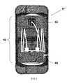
- FIG. 1is a perspective view of a first embodiment of a watch stand with the insert for the watch charger removed from the watch support surface and the post fully inserted and in the sleeve.
- FIG. 2is another perspective view of the watch stand depicted in FIG. 1 with the post height adjusted upward to reveal the charging cable extending from the watch charger and a helical cable management track that is incorporated into the exterior surface of the post.
- FIG. 3is a perspective view of the post component of the watch stand depicted in FIG. 1 and illustrating a hollow core and further illustrated the helical cable management track.
- FIGS. 4A-4Bare perspective views of the watch stand illustrated in FIG. 1 illustrating how a smart watch and smart phone may be positioned on the watch stand for storage and charging.
- the smartphoneis sitting on edge propped-up by a lip structure extending on one side of the watch stand and leaning on the sleeve of the watch stand.
- the smart watchis positioned in a landscape orientation on an angled support surface of the watch stand with the watch strap wrapped around the opposing side of the sleeve/post and the angled support surface configured to be generally facing toward the lip structure.
- FIG. 4Bthe smart watch is positioned in portrait orientation on the angled support surface with the watch strap hanging open with the angled support surface rotated 90 degrees from its orientation illustrated in FIG. 4A .
- FIGS. 5A-5Bare perspective views of another implementation of the watch stand illustrated in FIG. 1 that includes an extended base with an elevated wireless charging surface and showing how a smart watch and smart phone may be positioned on the watch stand for storage and charging.
- FIG. 5Aillustrates the smart phone laying on its backside on top of the wireless charging surface
- FIG. 5Billustrates the smart phone laying on edge propped-up by the sidewall of the wireless charging surface and leaning on the sleeve of the watch stand.
- FIG. 6is a bottom view of the watch stand depicted in FIGS. 5A-5B illustrating how the cable extends through the post and sleeve of the watch stand and is wrapped around a cable management system incorporated into the underside of the base component.
- FIGS. 1-6illustrate various views and constituent components of a convenient and user friendly watch stand implementations.
- FIGS. 1-4Billustrate a first embodiment of a watch stand 10 having a base support 11 including a top surface and an opposing bottom surface configured to stand on a support surface such as a desk or table, a sleeve 12 extending from the top surface of the base support 11 at a first end section to an open ended second end section, and a post 13 extending from a first end region to a second end region and being configured to slide into the sleeve 12 at its first end region via the opening at the second end section of the sleeve 12 .
- the top surface of the base support 11is inclined or slopped as it extends from a first side toward an opposing second side.
- a lip structure 18extends upward from the opposing second side to retain and provide support to a mobile device, such as a smart phone positioned on the base, as best illustrated in FIGS. 4A and 4B .
- the sleeve 12is formed of a multi-sided structure that defines a passageway for insertion of the post 13 .
- the terminations of the wall structures that form the sides at the second end sectionprovide an angled edge surface that serves to support a corresponding mating edge surface of the post 13 when the post 13 is fully inserted into the sleeve 12 .
- the post 13includes an angled watch support surface 14 at the second end region, which includes a cavity to house a watch charger 17 .
- An insert or lifter 19may be provided to fit into the cavity to facilitate positioning of the charger in the cavity.
- the post 13further includes a helical groove or track 15 that encircles its exterior surface from below the angled support surface 14 to the first end region. As best illustrated in FIG. 2 , the helical track 15 is dimensioned to receive and manage a power cable 16 that extends from the watch charger 17 that is housed within the cavity opening on the angled support surface 14 . Also as best illustrated in FIG. 2 , the height of the post 13 above the base 11 may be adjusted upward from a fully inserted position (illustrated for example in FIG.
- the post 13may be hollow to allow for additional storage for example for a battery.
- FIGS. 4A and 4Bdepict how a smart watch 20 and smart phone 30 may be positioned on the watch stand 10 for storage and charging.
- the smartphone 30is sitting on edge supported or propped-up by a lip structure 18 extending on one side of the watch stand and leaning on the sleeve 12 of the watch stand 10 .
- the smart watch 20is positioned in a landscape orientation on the angled support surface 14 of the watch stand 10 with the watch strap wrapped around the opposing side of the sleeve/post and the angled support surface 14 oriented so that it is generally facing toward the lip structure 18 .
- the smart watch 20is positioned in portrait orientation on the angled support surface 14 with the watch strap hanging open and the angled support surface 14 being rotated 90 degrees from its orientation illustrated in FIG. 4A .
- FIGS. 5A-6illustrate another embodiment of a watch stand 10 ′ which like the watch stand 10 embodiment previously described in connection with FIGS. 1-4B , includes a base support 11 ′ having a top surface and an opposing bottom surface configured to stand on a support surface such as a desk or table, a sleeve 12 extending from the top surface of the base support 11 ′ at a first end section to an open-ended second end section, and a post 13 extending from a first end region to a second end region and being configured to slide into the sleeve 12 at its first end region via the opening at the second end section of the sleeve 12 .
- FIGS. 5A-6differs from that of FIGS. 1-4B in that the base support 11 ′ is extended to include an elevated wireless charging surface 41 on its top surface and a cable management system 42 incorporated into its bottom surface.
- the side of the wireless charging surface 41 that is proximate to the sleeve 12forms a wall that serves to support mobile devices e.g., the smart phone, like the lip structure 18 previously described.
- the cable management system 42is comprised of a first support post 43 and a second support post 44 that are spaced apart and adapted so that the a charging cable can be wrapped around them yet concealed within the base support 11 ′ when the base support 11 ′ is standing upright a top a support surface such as that depicted in FIGS. 5A and 5B .
- the watch charger 17is inserted into the watch charger cavity at the top end of the post 13 and the charging cable 16 is wrapped around the helical track 15 on the exterior of the post 13 .
- the post 13is then inserted into the sleeve 12 at the desired orientation and height.
- the charging cablemay be wrapped around the cable management system 41 located on the underside of the base support as illustrated in FIG. 6 .
- a smart watch 20can then be positioned, supported and charged a top the watch support surface 14 in the desired portrait or landscape orientation as illustrated in FIGS. 4A-B and 5 A-B. Additional mobile devices such as a smart phone 30 can be stored and charged on the watch stand either via a charging cable or if such devices are wireless chargeable then via the wireless charging surface 41 .
Landscapes
- Engineering & Computer Science (AREA)
- General Engineering & Computer Science (AREA)
- Mechanical Engineering (AREA)
- Power Engineering (AREA)
- Physics & Mathematics (AREA)
- General Physics & Mathematics (AREA)
- Computer Networks & Wireless Communication (AREA)
- Charge And Discharge Circuits For Batteries Or The Like (AREA)
- Telephone Set Structure (AREA)
Abstract
Description
Claims (11)
Priority Applications (2)
| Application Number | Priority Date | Filing Date | Title |
|---|---|---|---|
| US15/331,107US9996055B2 (en) | 2015-10-22 | 2016-10-21 | Watch stand |
| US16/002,753US10816938B2 (en) | 2015-10-22 | 2018-06-07 | Watch stand |
Applications Claiming Priority (2)
| Application Number | Priority Date | Filing Date | Title |
|---|---|---|---|
| US201562244907P | 2015-10-22 | 2015-10-22 | |
| US15/331,107US9996055B2 (en) | 2015-10-22 | 2016-10-21 | Watch stand |
Related Child Applications (1)
| Application Number | Title | Priority Date | Filing Date |
|---|---|---|---|
| US16/002,753ContinuationUS10816938B2 (en) | 2015-10-22 | 2018-06-07 | Watch stand |
Publications (2)
| Publication Number | Publication Date |
|---|---|
| US20170115640A1 US20170115640A1 (en) | 2017-04-27 |
| US9996055B2true US9996055B2 (en) | 2018-06-12 |
Family
ID=58558492
Family Applications (2)
| Application Number | Title | Priority Date | Filing Date |
|---|---|---|---|
| US15/331,107Active2036-12-14US9996055B2 (en) | 2015-10-22 | 2016-10-21 | Watch stand |
| US16/002,753ActiveUS10816938B2 (en) | 2015-10-22 | 2018-06-07 | Watch stand |
Family Applications After (1)
| Application Number | Title | Priority Date | Filing Date |
|---|---|---|---|
| US16/002,753ActiveUS10816938B2 (en) | 2015-10-22 | 2018-06-07 | Watch stand |
Country Status (1)
| Country | Link |
|---|---|
| US (2) | US9996055B2 (en) |
Cited By (10)
| Publication number | Priority date | Publication date | Assignee | Title |
|---|---|---|---|---|
| USD852135S1 (en)* | 2019-01-29 | 2019-06-25 | Shenzhenshi Minglangxingsujiaomoju Youxian Gongsi | Wireless charging stand |
| USD852134S1 (en)* | 2019-01-29 | 2019-06-25 | Shenzhenshi Minglangxingsujiaomoju Youxian Gongsi | Wireless charging stand |
| USD857626S1 (en)* | 2018-05-31 | 2019-08-27 | Ugreen Group Limited | Wireless charger |
| US10530176B2 (en)* | 2016-03-02 | 2020-01-07 | Andrew Bradford Green | Travel case and stand for smart watch |
| USD884622S1 (en)* | 2019-03-21 | 2020-05-19 | Xiaozhuan Huang | Charging stand for smart watch |
| USD889403S1 (en)* | 2019-12-11 | 2020-07-07 | Songzhen Li | Wireless charging bracket |
| USD948253S1 (en)* | 2020-03-31 | 2022-04-12 | The Watch Stand Global AB | Watch stand |
| USD971849S1 (en)* | 2020-08-06 | 2022-12-06 | Yuyi Lee | Tower dock |
| USD1025904S1 (en)* | 2023-12-04 | 2024-05-07 | Ruibao Gao | Combination light and charging base |
| USD1054982S1 (en)* | 2023-12-02 | 2024-12-24 | Ruibao Gao | Combination lights and charging base |
Families Citing this family (2)
| Publication number | Priority date | Publication date | Assignee | Title |
|---|---|---|---|---|
| CN109921488B (en)* | 2019-03-21 | 2022-12-02 | 深圳市聚泉鑫科技有限公司 | Two unification cell-phones are wireless fills and wireless fills of wrist-watch |
| CN111443588A (en)* | 2020-05-19 | 2020-07-24 | 吴铭 | Smart Watch Extension Dock and Smart Watch Components |
Citations (9)
| Publication number | Priority date | Publication date | Assignee | Title |
|---|---|---|---|---|
| US4873677A (en)* | 1987-07-10 | 1989-10-10 | Seiko Epson Corporation | Charging apparatus for an electronic device |
| US5752600A (en)* | 1996-05-13 | 1998-05-19 | Seiko Kabushiki Kaisha Hattori Seiko | Watch package and display stand |
| US20130336709A1 (en)* | 2011-04-05 | 2013-12-19 | Wilhelm Layher Verwaltungs-Gmbh | Scaffolding post |
| US8714813B2 (en)* | 2010-10-04 | 2014-05-06 | Gooten Innolife Corporation | Watch winder having wireless energy transferring function |
| US20160012968A1 (en)* | 2014-07-11 | 2016-01-14 | Powerwow Technology Inc | Receiver coil part and wearable device with same |
| US20160261139A1 (en)* | 2015-03-08 | 2016-09-08 | Michael Kidakarn | Multipurpose Charging and Display Stand for a Computerized Wristwatch |
| US9577467B1 (en)* | 2015-09-08 | 2017-02-21 | Apple Inc. | Hinge assembly for a wireless charger |
| US20170133874A1 (en)* | 2015-10-20 | 2017-05-11 | Joanne Loewen | Mobile Device Charging and Docking Station |
| US9831713B2 (en)* | 2015-03-05 | 2017-11-28 | Seiko Instruments Inc. | Antenna unit and portable electronic apparatus |
Family Cites Families (1)
| Publication number | Priority date | Publication date | Assignee | Title |
|---|---|---|---|---|
| WO2007111078A1 (en)* | 2006-03-27 | 2007-10-04 | Nec Corporation | Desktop charger holder |
- 2016
- 2016-10-21USUS15/331,107patent/US9996055B2/enactiveActive
- 2018
- 2018-06-07USUS16/002,753patent/US10816938B2/enactiveActive
Patent Citations (9)
| Publication number | Priority date | Publication date | Assignee | Title |
|---|---|---|---|---|
| US4873677A (en)* | 1987-07-10 | 1989-10-10 | Seiko Epson Corporation | Charging apparatus for an electronic device |
| US5752600A (en)* | 1996-05-13 | 1998-05-19 | Seiko Kabushiki Kaisha Hattori Seiko | Watch package and display stand |
| US8714813B2 (en)* | 2010-10-04 | 2014-05-06 | Gooten Innolife Corporation | Watch winder having wireless energy transferring function |
| US20130336709A1 (en)* | 2011-04-05 | 2013-12-19 | Wilhelm Layher Verwaltungs-Gmbh | Scaffolding post |
| US20160012968A1 (en)* | 2014-07-11 | 2016-01-14 | Powerwow Technology Inc | Receiver coil part and wearable device with same |
| US9831713B2 (en)* | 2015-03-05 | 2017-11-28 | Seiko Instruments Inc. | Antenna unit and portable electronic apparatus |
| US20160261139A1 (en)* | 2015-03-08 | 2016-09-08 | Michael Kidakarn | Multipurpose Charging and Display Stand for a Computerized Wristwatch |
| US9577467B1 (en)* | 2015-09-08 | 2017-02-21 | Apple Inc. | Hinge assembly for a wireless charger |
| US20170133874A1 (en)* | 2015-10-20 | 2017-05-11 | Joanne Loewen | Mobile Device Charging and Docking Station |
Cited By (10)
| Publication number | Priority date | Publication date | Assignee | Title |
|---|---|---|---|---|
| US10530176B2 (en)* | 2016-03-02 | 2020-01-07 | Andrew Bradford Green | Travel case and stand for smart watch |
| USD857626S1 (en)* | 2018-05-31 | 2019-08-27 | Ugreen Group Limited | Wireless charger |
| USD852135S1 (en)* | 2019-01-29 | 2019-06-25 | Shenzhenshi Minglangxingsujiaomoju Youxian Gongsi | Wireless charging stand |
| USD852134S1 (en)* | 2019-01-29 | 2019-06-25 | Shenzhenshi Minglangxingsujiaomoju Youxian Gongsi | Wireless charging stand |
| USD884622S1 (en)* | 2019-03-21 | 2020-05-19 | Xiaozhuan Huang | Charging stand for smart watch |
| USD889403S1 (en)* | 2019-12-11 | 2020-07-07 | Songzhen Li | Wireless charging bracket |
| USD948253S1 (en)* | 2020-03-31 | 2022-04-12 | The Watch Stand Global AB | Watch stand |
| USD971849S1 (en)* | 2020-08-06 | 2022-12-06 | Yuyi Lee | Tower dock |
| USD1054982S1 (en)* | 2023-12-02 | 2024-12-24 | Ruibao Gao | Combination lights and charging base |
| USD1025904S1 (en)* | 2023-12-04 | 2024-05-07 | Ruibao Gao | Combination light and charging base |
Also Published As
| Publication number | Publication date |
|---|---|
| US20170115640A1 (en) | 2017-04-27 |
| US20180284699A1 (en) | 2018-10-04 |
| US10816938B2 (en) | 2020-10-27 |
Similar Documents
| Publication | Publication Date | Title |
|---|---|---|
| US10816938B2 (en) | Watch stand | |
| KR101285084B1 (en) | Wireless charger with cradling function for portable device | |
| CN102651516B (en) | Base and the electronic equipment with base | |
| US9059592B2 (en) | Fixing apparatus with wireless charging | |
| US20140354219A1 (en) | Wireless charging apparatus | |
| US8675356B2 (en) | System and, method for holding and powering three consumer electronic devices | |
| US8183830B2 (en) | Adjustable charger | |
| US20150011265A1 (en) | Support Apparatus for Mobile Device | |
| TWM493192U (en) | Wireless charging dock in flat or angled position | |
| US9143180B2 (en) | Cell phone charger holder | |
| US8593804B2 (en) | System, method and apparatus for holding multiple devices | |
| US20120227636A1 (en) | Tripod stand | |
| US20140139183A1 (en) | Mobile Device Charger With Support Stand System | |
| WO2019178648A1 (en) | Improved wireless charging station | |
| US20120228441A1 (en) | Flexible and retractable support arm for electronic devices | |
| US8474775B2 (en) | Foldable and adjustable supporting apparatus for portable devices | |
| CN209497283U (en) | A kind of split type two-way charging equipment | |
| KR20170069827A (en) | Auxiliary battery charger of a mobile phone provided with a stand that can be size adjustment | |
| KR101462773B1 (en) | Frame or cell phone Cover that consists of cell phone Prop System of Length and Breadth | |
| KR101340441B1 (en) | Holder for portable display apparatus | |
| CN100571352C (en) | Thin display device and method for pulling out display part thereof | |
| KR200485571Y1 (en) | Narrow table having of grooved goods | |
| CN108933461A (en) | Instant-plugging tumbler charger baby | |
| KR101868977B1 (en) | Rotatable reverse-v type cell phone device | |
| US20250088016A1 (en) | Electronic Device Charging Stand with Adjustable Support |
Legal Events
| Date | Code | Title | Description |
|---|---|---|---|
| STCF | Information on status: patent grant | Free format text:PATENTED CASE | |
| AS | Assignment | Owner name:WELLS FARGO BANK, NATIONAL ASSOCIATION, AS ADMINISTRATIVE AGENT, CALIFORNIA Free format text:SECURITY INTEREST;ASSIGNOR:GRIFFIN TECHNOLOGY, LLC;REEL/FRAME:047247/0934 Effective date:20180706 Owner name:WELLS FARGO BANK, NATIONAL ASSOCIATION, AS ADMINIS Free format text:SECURITY INTEREST;ASSIGNOR:GRIFFIN TECHNOLOGY, LLC;REEL/FRAME:047247/0934 Effective date:20180706 | |
| AS | Assignment | Owner name:MONROE CAPITAL MANAGEMENT ADVISORS, LLC, ILLINOIS Free format text:SECURITY INTEREST;ASSIGNOR:GRIFFIN TECHNOLOGY, LLC;REEL/FRAME:046461/0149 Effective date:20180706 | |
| AS | Assignment | Owner name:MIDCAP FUNDING IV TRUST, MARYLAND Free format text:SECURITY INTEREST;ASSIGNORS:INCIPIO, LLC;INCASE DESIGNS CORP.;GRIFFIN TECHNOLOGY, LLC;AND OTHERS;REEL/FRAME:050129/0814 Effective date:20190521 | |
| AS | Assignment | Owner name:GRIFFIN TECHNOLOGY, LLC, CALIFORNIA Free format text:RELEASE OF SECURITY INTEREST IN PATENTS AT REEL/FRAME NO. 47247/0934;ASSIGNOR:WELLS FARGO BANK, NATIONAL ASSOCIATION, AS ADMINISTRATIVE AGENT;REEL/FRAME:049672/0095 Effective date:20190521 | |
| AS | Assignment | Owner name:SIENA LENDING GROUP LLC, CONNECTICUT Free format text:SECURITY INTEREST;ASSIGNOR:ARMOR ACQUISITION LLC;REEL/FRAME:057112/0057 Effective date:20210806 | |
| MAFP | Maintenance fee payment | Free format text:PAYMENT OF MAINTENANCE FEE, 4TH YR, SMALL ENTITY (ORIGINAL EVENT CODE: M2551); ENTITY STATUS OF PATENT OWNER: SMALL ENTITY Year of fee payment:4 | |
| AS | Assignment | Owner name:ARMOR ACQUISITION LLC, CALIFORNIA Free format text:ASSIGNMENT OF ASSIGNORS INTEREST;ASSIGNOR:GRIFFIN TECHNOLOGY, LLC;REEL/FRAME:058899/0428 Effective date:20210806 | |
| AS | Assignment | Owner name:VINCI BRANDS LLC, CALIFORNIA Free format text:CHANGE OF NAME;ASSIGNOR:ARMOR ACQUISITION LLC;REEL/FRAME:059912/0179 Effective date:20210824 | |
| AS | Assignment | Owner name:VEVEY LLC, NEW YORK Free format text:ASSIGNMENT OF ASSIGNORS INTEREST;ASSIGNOR:ACS GROUP ACQUISITION LLC;REEL/FRAME:070610/0873 Effective date:20231201 Owner name:ACS GROUP ACQUISITION LLC, NEW YORK Free format text:ASSIGNMENT OF ASSIGNORS INTEREST;ASSIGNOR:VINCI BRANDS LLC;REEL/FRAME:070610/0783 Effective date:20231201 |