US9995990B2 - Removable camera lens cover - Google Patents
Removable camera lens coverDownload PDFInfo
- Publication number
- US9995990B2 US9995990B2US14/970,323US201514970323AUS9995990B2US 9995990 B2US9995990 B2US 9995990B2US 201514970323 AUS201514970323 AUS 201514970323AUS 9995990 B2US9995990 B2US 9995990B2
- Authority
- US
- United States
- Prior art keywords
- camera
- lens cover
- removable lens
- removable
- camera system
- Prior art date
- Legal status (The legal status is an assumption and is not a legal conclusion. Google has not performed a legal analysis and makes no representation as to the accuracy of the status listed.)
- Active, expires
Links
Images


Classifications
- G—PHYSICS
- G03—PHOTOGRAPHY; CINEMATOGRAPHY; ANALOGOUS TECHNIQUES USING WAVES OTHER THAN OPTICAL WAVES; ELECTROGRAPHY; HOLOGRAPHY
- G03B—APPARATUS OR ARRANGEMENTS FOR TAKING PHOTOGRAPHS OR FOR PROJECTING OR VIEWING THEM; APPARATUS OR ARRANGEMENTS EMPLOYING ANALOGOUS TECHNIQUES USING WAVES OTHER THAN OPTICAL WAVES; ACCESSORIES THEREFOR
- G03B11/00—Filters or other obturators specially adapted for photographic purposes
- G03B11/04—Hoods or caps for eliminating unwanted light from lenses, viewfinders or focusing aids
- G03B11/06—Lens caps for exposure making
- G—PHYSICS
- G03—PHOTOGRAPHY; CINEMATOGRAPHY; ANALOGOUS TECHNIQUES USING WAVES OTHER THAN OPTICAL WAVES; ELECTROGRAPHY; HOLOGRAPHY
- G03B—APPARATUS OR ARRANGEMENTS FOR TAKING PHOTOGRAPHS OR FOR PROJECTING OR VIEWING THEM; APPARATUS OR ARRANGEMENTS EMPLOYING ANALOGOUS TECHNIQUES USING WAVES OTHER THAN OPTICAL WAVES; ACCESSORIES THEREFOR
- G03B11/00—Filters or other obturators specially adapted for photographic purposes
- G03B11/04—Hoods or caps for eliminating unwanted light from lenses, viewfinders or focusing aids
- G03B11/041—Lens caps as separate accessory
- G—PHYSICS
- G03—PHOTOGRAPHY; CINEMATOGRAPHY; ANALOGOUS TECHNIQUES USING WAVES OTHER THAN OPTICAL WAVES; ELECTROGRAPHY; HOLOGRAPHY
- G03B—APPARATUS OR ARRANGEMENTS FOR TAKING PHOTOGRAPHS OR FOR PROJECTING OR VIEWING THEM; APPARATUS OR ARRANGEMENTS EMPLOYING ANALOGOUS TECHNIQUES USING WAVES OTHER THAN OPTICAL WAVES; ACCESSORIES THEREFOR
- G03B17/00—Details of cameras or camera bodies; Accessories therefor
- G03B17/02—Bodies
- G03B17/08—Waterproof bodies or housings
- G—PHYSICS
- G03—PHOTOGRAPHY; CINEMATOGRAPHY; ANALOGOUS TECHNIQUES USING WAVES OTHER THAN OPTICAL WAVES; ELECTROGRAPHY; HOLOGRAPHY
- G03B—APPARATUS OR ARRANGEMENTS FOR TAKING PHOTOGRAPHS OR FOR PROJECTING OR VIEWING THEM; APPARATUS OR ARRANGEMENTS EMPLOYING ANALOGOUS TECHNIQUES USING WAVES OTHER THAN OPTICAL WAVES; ACCESSORIES THEREFOR
- G03B17/00—Details of cameras or camera bodies; Accessories therefor
- G03B17/02—Bodies
- G03B17/12—Bodies with means for supporting objectives, supplementary lenses, filters, masks, or turrets
- G—PHYSICS
- G03—PHOTOGRAPHY; CINEMATOGRAPHY; ANALOGOUS TECHNIQUES USING WAVES OTHER THAN OPTICAL WAVES; ELECTROGRAPHY; HOLOGRAPHY
- G03B—APPARATUS OR ARRANGEMENTS FOR TAKING PHOTOGRAPHS OR FOR PROJECTING OR VIEWING THEM; APPARATUS OR ARRANGEMENTS EMPLOYING ANALOGOUS TECHNIQUES USING WAVES OTHER THAN OPTICAL WAVES; ACCESSORIES THEREFOR
- G03B17/00—Details of cameras or camera bodies; Accessories therefor
- G03B17/55—Details of cameras or camera bodies; Accessories therefor with provision for heating or cooling, e.g. in aircraft
Definitions
- This disclosurerelates to cameras, and more specifically, to a removable lens cover for a camera.
- FIG. 1illustrates the components of an example camera system, according to one embodiment.
- FIG. 2Aillustrates a perspective view of a camera for use with the camera system, according to one embodiment.
- FIG. 2Billustrates a perspective view of a rear of a camera for use with the camera system, according to one embodiment.
- FIGS. 3A and 3Billustrate the rotation of a removable camera lens cover to secure the lens cover to a camera, according to one embodiment.
- FIG. 4illustrates a perspective view of a rear side of the removable camera lens cover of FIG. 3 , according to one embodiment.
- FIG. 5illustrates a perspective view of a camera for use with a removable lens cover, according to one embodiment.
- FIGS. 6A and 6Billustrate a cross-sectional view of a mechanism for securing a removable lens cover to a camera, according to one embodiment.
- a camerais configured for use with a removable camera lens cover.
- the lens covercan be secured to or removed from the camera by a user without the use of a tool set.
- the mechanism which allows the lens cover to be secured to and removed from the cameraincludes a set of wires embedded into the lens cover and a set of wedges protruding from the lens wall of the camera.
- the wiresare secured onto a rear surface of the lens cover with a securing mechanism, such as screws.
- the wedgesprotrude from the outside surface of the lens wall opposite each other and taper outwards towards the normal plane of the lens wall.
- the lens coverincludes a hole within the rear surface of the lens cover to accommodate the lens wall of the camera.
- the lens coveris placed over the lens wall of the camera such that the hole within the rear surface of the lens cover is aligned with the lens wall and until the rear surface of the lens cover abuts a front surface of the lens wall. Subsequently, the lens cover is rotated relative to the camera until each wire aligns with a corresponding different wedge. In this configuration, the wires of the lens cover are secured underneath the tapered surface of the wedges of the camera, preventing the lens cover from being removed from or rotating relative to the camera.
- a forceis applied to the lens cover away from and normal to the front surface of the camera. The applied force causes the wires of the lens cover to slide along the corresponding tapered surface of the wedges of the camera, flexing the wires outward and away from each other and enabling the rotation, and thereby removal, of the lens cover from the camera.
- FIG. 1is a block diagram illustrating electronic components of a camera 100 , according to one embodiment.
- the camera 100 of the embodiment of FIG. 1includes one or more microcontrollers 102 , a system memory 104 , a synchronization interface 106 , a controller hub 108 , one or more microphone controllers 110 , an image sensor 112 , a lens and focus controller 114 , a color model engine 116 , one or more lenses 120 , one or more LED lights 122 , one or more buttons 124 , one or more microphones 126 , an I/O port interface 128 , a display 130 , and an expansion pack interface 132 .
- the camera 100includes one or more microcontrollers 102 (such as a processor) that control the operation and functionality of the camera 100 .
- the microcontrollers 102can execute computer instructions stored on the memory 104 to perform the functionality described herein.
- the camera 100can capture image data, can provide the image data to an external system (such as a computer, a mobile phone, or another camera), and the external system can generate a LUT based on the captured image data.
- a lens and focus controller 114is configured to control the operation, configuration, and focus of the camera lens 120 , for instance based on user input or based on analysis of captured image data.
- the image sensor 112is a device capable of electronically capturing light incident on the image sensor 112 and converting the captured light to image data.
- the image sensor 112can be a CMOS sensor, a CCD sensor, or any other suitable type of image sensor, and can include corresponding transistors, photodiodes, amplifiers, analog-to-digital converters, and power supplies.
- a system memory 104is configured to store executable computer instructions that, when executed by the microcontroller 102 , perform the camera functionalities described herein.
- the system memory 104also stores images captured using the lens 120 and image sensor 112 .
- the memory 104can include volatile memory (e.g., random access memory (RAM)), non-volatile memory (e.g., a flash memory), or a combination thereof.
- a synchronization interface 106is configured to communicatively couple the camera 100 with external devices, such as a remote control, another camera (such as a slave camera or master camera), a computer, or a smartphone.
- the synchronization interface 106may transfer information through a network, which allows coupled devices, including the camera 100 , to exchange data other over local-area or wide-area networks.
- the networkmay contain a combination of wired or wireless technology and make use of various connection standards and protocols, such as WiFi, IEEE 1394, Ethernet, 802.11, 4G, or Bluetooth.
- a controller hub 108transmits and receives information from user I/O components.
- the controller hub 108interfaces with the LED lights 122 , the display 130 , and the buttons 124 .
- the controller hub 108can interface with any conventional user I/O component or components.
- the controller hub 308may send information to other user I/O components, such as a speaker.
- a microphone controller 110receives and captures audio signals from one or more microphones, such as microphone 126 A and microphone 126 B.
- the microphone controller 110is configured to control the operation of the microphones 126 .
- the microphone controller 110selects which microphones from which audio data is captured. For instance, for a camera 100 with multiple microphone pairs, the microphone controller 110 selects one microphone of the pair to capture audio data.
- I/O port interface 128may facilitate the camera 100 in receiving or transmitting video or audio information through an I/O port.
- I/O ports or interfacesinclude USB ports, HDMI ports, Ethernet ports, audioports, and the like.
- embodiments of the I/O port interface 128may include wireless ports that can accommodate wireless connections. Examples of wireless ports include Bluetooth, Wireless USB, Near Field Communication (NFC), and the like.
- the expansion pack interface 132is configured to interface with camera add-ons and removable expansion packs, such as an extra battery module, a wireless module, and the like.
- FIG. 2Aillustrates a camera 200 for use with the camera systems described herein, according to one example embodiment.
- the camera 200is configured to capture images and video, and to store captured images and video for subsequent display or playback.
- the camera 200is adapted to fit within a camera housing, such as the housing 100 discussed above or any other housing described herein.
- the camera 200includes a lens 202 configured to receive light incident upon the lens and to direct received light onto an image sensor internal to the lens.
- the lens 202is enclosed by a lens ring 204 .
- the camera 200can include various indicators, including the LED lights 206 and the LED display 208 shown in FIG. 2A .
- the LED display 208is configured to substantially align with the indicator window 106 , and the LED lights 206 are configured to be visible through the housing 100 .
- the camera 200can also include buttons 210 configured to allow a user of the camera to interact with the camera, to turn the camera on, and to otherwise configure the operating mode of the camera.
- the camera 200can also include one or more microphones 212 configured to receive and record audio signals in conjunction with recording video.
- the side of the camera 200includes an I/O interface 214 . Though the embodiment of FIG. 2A illustrates the I/O interface 214 enclosed by a protective door, the I/O interface can include any type or number of I/O ports or mechanisms, such as USC ports, HDMI ports, memory card slots, and the like.
- FIG. 2Billustrates a perspective view of a rear of a camera 200 for use with the camera system, according to one embodiment.
- the camera 200includes a display 218 configured to display camera information or image information (such as captured images or viewfinder images).
- the cameraalso includes an expansion pack interface 220 configured to receive a removable expansion pack, such as a display module, an extra battery module, a wireless module, and the like. Removable expansion packs, when coupled to the camera 200 , provide additional functionality to the camera via the expansion pack interface 220 .
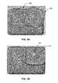
- FIGS. 3A and 3Billustrate the rotation of a removable camera lens cover to secure the lens cover to a camera, according to one embodiment.
- the removable lens cover 300is placed over the lens of and onto the front surface of the camera 200 in a rotated position relative to the camera, illustrating an unlocked configuration.
- the removable lens cover 300can be removed from the camera 200 or can be rotated and secured to the camera.
- the removable lens cover 300is shown in a locked configuration.
- the removable lens cover 300is rotated from the unlocked configuration illustrated in FIG. 3A to the orientation illustrated in FIG. 3B , thereby securing the removable lens cover to the camera 200 .
- the removable lens coverwhen the removable lens cover 300 is in the unlocked configuration, the removable lens cover can be rotated clockwise or counter-clockwise relative to the camera 200 to configure the removable lens cover into the locked configuration.
- the removable lens cover 300is substantially rectangular in shape with rounded corners, though in other embodiments, the removable lens cover can be any suitable shape.
- the removable lens cover 300includes an outer wall with a top segment, a bottom segment, a left segment, and a right segment.
- the removable lens coveralso includes a transparent protective lens surface 302 affixed to the outer wall.
- one or more of the top segment, the bottom segment, the right segment, and the left segmentare either substantially parallel with one or more surfaces of the camera 200 or are substantially flush with one or more surfaces of the camera.
- the top segment and the right segment of the removable lens cover outer wallare substantially flush with the top surface and the right surface of the camera 200 , respectively.
- the protective lens surface 302shields the lens 202 of the camera 200 from outside elements which can cause damage to the lens.
- a watertight sealis created between a rear surface of the removable lens cover 300 and a front surface of the camera 200 , creating a cavity between the camera and the removable lens cover and preventing water, debris, and other outside elements from entering the cavity and causing damage to the camera.
- a portion of the outer wall of the removable lens cover 300is made of a thermally conductive material and acts as a heat sink for the excess heat created by camera components (such as image processors, image sensors, and the like) thermally coupled to the outer wall by a thermal conduit adjacent to or abutting the camera components and the outer wall.
- thermal conduitwhich can be located within the camera
- thermal conduitwhich can be located within the camera
- thermally conductive materialof the outer wall of the removable lens cover, where it is dissipated, for instance by water or air.
- thermal channelsprovide a pathway to transfer the excess heat from internal camera components out of the camera 200 via the removable lens cover 300 , preventing overheating and potential damage to the camera.
- FIG. 4illustrates a perspective view of a rear side of the removable camera lens cover of FIG. 3 , according to one embodiment.
- the rear side of the removable lens cover 300includes a lens hole 404 located in the center of the removable lens cover, aligning with the lens 202 of the camera 200 when the removable lens cover is configured in the locked configuration.
- Surrounding the lens hole 404is a plurality of notches 408 protruding outward from the rear surface and radially away from the lens hole.
- the plurality of notches 408interlock with a reciprocal plurality of grooves on the camera 200 to ensure correct alignment of the removable lens cover 300 when it is configured in the locked configuration with the camera.
- the plurality of notches 408are substantially rectangular in shape, but in other embodiments, the plurality of notches can be any shape, size, or configuration.
- the rear side of the removable lens cover 300also includes a plurality of flexible securing structures 400 a and 400 b (collectively “ 400 ” hereinafter).
- the flexible securing structures 400can be a set of wires in a parallel configuration on opposite sides of the removable lens cover 300 .
- each end of each wireis embedded into a partial channel (such as partial channel 410 ) on the rear side of the removable lens cover 300 .
- the ends of the wiresare secured into the partial channels, for instance, using screws 406 , latches, adhesives, or any suitable securing mechanism.
- each end of a wireis embedded into one of a corresponding pair of partial channels, each partial channel in the pair of partial channels being substantially aligned and/or collinear. Spanning between each pair of partial channels is a clearance space for wedges of the camera 200 (as described below), beneficially allowing the wedges to abut the flexible securing structures 400 in the locked configuration.
- the material of the flexible securing structures 400can be made of a type of metal, such as aluminum or steel, and can be rigid enough to retain its position in the locked configuration but flexible enough to allow the removable lens cover 300 to be removed from the camera 200 .
- the flexible securing structures 400may be rods, cylinders, pins, dowels, and the like.
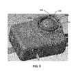
- FIG. 5illustrates a perspective view of a camera for use with a removable lens cover, according to one embodiment.
- the camera 200includes a lens wall 500 which surrounds the lens 202 .
- the lens wall 500includes a plurality of wedges 504 that protrude and taper outwards from the outside surface 502 of the lens wall 500 .
- each wedge 504corresponds to a reciprocal flexible securing structure 400 such that each wedge aligns with a reciprocal flexible securing structure when the removable lens cover 300 is in the locked configuration.
- each wedge 504is configured such that it will secure a flexible securing structure 400 underneath the tapered surface of the wedge when the removable lens cover 300 is in the locked configuration.
- the flexible securing structuresubstantially abuts a portion of the tapered surface of the wedge 504 , preventing the removable lens cover 300 from rotating absent the application of an outward force being applied to the removable lens cover and securing the removable lens cover to the front surface 506 of the camera 200 .
- each wedge 504applies an outward force on the reciprocal flexible securing structure 400 , but the applied force is less than a threshold force required to flex the flexible securing structure outward enough such that the removable lens cover 300 can be rotated relative to the camera 200 .
- a threshold forceis applied on the removable lens cover outward and normal to the camera, the wedges 504 exert a corresponding force on the flexible securing structures 400 , causing the flexible securing structures to flex outward and away from the lens wall 500 , beneficially enabling the removable lens cover to rotate relative to the camera such that the removable lens cover can be configured from the locked configuration into the unlocked configuration, and thus removed from the camera 200 .
- the camera 200also includes a plurality of grooves 508 indented into the top surface of the lens wall 500 .
- the locations and shape of the plurality of grooves 508correspond to the locations and shape of the plurality of notches 408 on the removable lens cover 300 . Accordingly, when the removable lens cover 300 is in the locked configuration, each of the plurality of notches 408 is inserted into a corresponding groove 508 , beneficially ensuring the correct alignment of the removable lens cover when it is in a locked configuration and further preventing the rotation of the removable lens cover.
- FIG. 6Aillustrates a cross-sectional view of a mechanism for securing a removable lens cover to a camera, according to one embodiment.
- the illustrated cross-sectionshows the camera 200 and the removable lens cover 300 in the locked configuration.
- the rear surface of the removable lens cover 300abuts the lens wall 500
- the flexible securing structures 400abut the tapered surfaces of the corresponding wedges 504 of the camera 200 .
- the distance d 604represents the distance between the flexible securing structures 400 .
- the distance d 604is at its minimum length, allowing the plurality of flexible securing structures 400 to substantially retain their position underneath the plurality of wedges 504 and preventing the removable lens cover 300 from rotating relative to and being removed from the camera 200 .
- FIG. 6Billustrates a perspective, cross-sectional view of a mechanism for removing a removable lens cover from a camera, according to one embodiment.
- a threshold force 600is applied to the removable lens cover by a user of the camera, outwardly normal to the front surface of the removable lens cover.
- the threshold force 600causes the wedge to apply a reciprocal force 602 to the flexible securing structure 400 , thereby causing the flexible securing structure to flex outward and slide along the tapered surface away from the lens wall 500 .
- the wedges 504are configured in an opposite configuration such that the threshold force 600 applied to the removable lens cover 300 is inwardly normal to the front surface of the removable lens cover, causing a reciprocal force to flex the flexible securing structures outward.
- FIGS. 3 through 6employ a rotating mechanism to secure the removable lens cover 300 to the camera 200 .
- the removable lens cover 300could be attached to the camera 200 through other securing mechanisms, such as a sliding fit, a snapping fit, a threaded fit, and the like, which allow a user to easily secure and remove a removable lens cover from a camera without the use of a tool set.
- Coupledalong with its derivatives.
- the term “coupled” as used hereinis not necessarily limited to two or more elements being in direct physical or electrical contact. Rather, the term “coupled” may also encompass two or more elements are not in direct contact with each other, but yet still co-operate or interact with each other, or are structured to provide a thermal conduction path between the elements.
- the terms “comprises,” “comprising,” “includes,” “including,” “has,” “having” or any other variation thereof,are intended to cover a non-exclusive inclusion.
- a process, method, article, or apparatus that comprises a list of elementsis not necessarily limited to only those elements but may include other elements not expressly listed or inherent to such process, method, article, or apparatus.
- any reference to “one embodiment” or “an embodiment”means that a particular element, feature, structure, or characteristic described in connection with the embodiment is included in at least one embodiment.
- the appearances of the phrase “in one embodiment” in various places in the specificationare not necessarily all referring to the same embodiment.
Landscapes
- Physics & Mathematics (AREA)
- General Physics & Mathematics (AREA)
- Engineering & Computer Science (AREA)
- Aviation & Aerospace Engineering (AREA)
- Structure And Mechanism Of Cameras (AREA)
- Studio Devices (AREA)
Abstract
Description
Claims (19)
Priority Applications (6)
| Application Number | Priority Date | Filing Date | Title |
|---|---|---|---|
| US14/970,323US9995990B2 (en) | 2015-12-15 | 2015-12-15 | Removable camera lens cover |
| US16/005,043US10401705B2 (en) | 2015-12-15 | 2018-06-11 | Removable camera lens cover |
| US16/541,760US10845675B2 (en) | 2015-12-15 | 2019-08-15 | Removable camera lens cover |
| US17/093,246US11543733B2 (en) | 2015-12-15 | 2020-11-09 | Removable camera lens cover |
| US18/083,772US11846870B2 (en) | 2015-12-15 | 2022-12-19 | Removable camera lens cover |
| US18/387,597US12292670B2 (en) | 2015-12-15 | 2023-11-07 | Removable camera lens cover |
Applications Claiming Priority (1)
| Application Number | Priority Date | Filing Date | Title |
|---|---|---|---|
| US14/970,323US9995990B2 (en) | 2015-12-15 | 2015-12-15 | Removable camera lens cover |
Related Child Applications (1)
| Application Number | Title | Priority Date | Filing Date |
|---|---|---|---|
| US16/005,043ContinuationUS10401705B2 (en) | 2015-12-15 | 2018-06-11 | Removable camera lens cover |
Publications (2)
| Publication Number | Publication Date |
|---|---|
| US20170168374A1 US20170168374A1 (en) | 2017-06-15 |
| US9995990B2true US9995990B2 (en) | 2018-06-12 |
Family
ID=59019671
Family Applications (6)
| Application Number | Title | Priority Date | Filing Date |
|---|---|---|---|
| US14/970,323Active2036-11-15US9995990B2 (en) | 2015-12-15 | 2015-12-15 | Removable camera lens cover |
| US16/005,043ActiveUS10401705B2 (en) | 2015-12-15 | 2018-06-11 | Removable camera lens cover |
| US16/541,760ActiveUS10845675B2 (en) | 2015-12-15 | 2019-08-15 | Removable camera lens cover |
| US17/093,246Active2036-03-30US11543733B2 (en) | 2015-12-15 | 2020-11-09 | Removable camera lens cover |
| US18/083,772ActiveUS11846870B2 (en) | 2015-12-15 | 2022-12-19 | Removable camera lens cover |
| US18/387,597ActiveUS12292670B2 (en) | 2015-12-15 | 2023-11-07 | Removable camera lens cover |
Family Applications After (5)
| Application Number | Title | Priority Date | Filing Date |
|---|---|---|---|
| US16/005,043ActiveUS10401705B2 (en) | 2015-12-15 | 2018-06-11 | Removable camera lens cover |
| US16/541,760ActiveUS10845675B2 (en) | 2015-12-15 | 2019-08-15 | Removable camera lens cover |
| US17/093,246Active2036-03-30US11543733B2 (en) | 2015-12-15 | 2020-11-09 | Removable camera lens cover |
| US18/083,772ActiveUS11846870B2 (en) | 2015-12-15 | 2022-12-19 | Removable camera lens cover |
| US18/387,597ActiveUS12292670B2 (en) | 2015-12-15 | 2023-11-07 | Removable camera lens cover |
Country Status (1)
| Country | Link |
|---|---|
| US (6) | US9995990B2 (en) |
Cited By (9)
| Publication number | Priority date | Publication date | Assignee | Title |
|---|---|---|---|---|
| US20180292731A1 (en)* | 2015-12-15 | 2018-10-11 | Gopro, Inc. | Removable Camera Lens Cover |
| US10306129B1 (en)* | 2016-06-28 | 2019-05-28 | Amazon Technologies, Inc. | Local and remote video-camera control |
| US11425286B2 (en) | 2020-03-31 | 2022-08-23 | Gopro, Inc. | Housing assembly for image capture devices |
| USD967890S1 (en) | 2020-08-28 | 2022-10-25 | Gopro, Inc. | Camera lens attachment |
| US11528417B2 (en) | 2020-08-31 | 2022-12-13 | Gopro, Inc. | Calibrating an image capture device with a detachable lens |
| USD974450S1 (en) | 2020-08-28 | 2023-01-03 | Gopro, Inc. | Camera lens attachment |
| US11586099B2 (en) | 2020-09-21 | 2023-02-21 | Aptiv Technologies Limited | Automotive camera with integrated induction heater |
| US11600023B2 (en) | 2020-08-31 | 2023-03-07 | Gopro, Inc. | Optical center calibration |
| US11630376B2 (en) | 2020-06-18 | 2023-04-18 | Gopro, Inc. | Removable lens accessories for image capture devices |
Families Citing this family (10)
| Publication number | Priority date | Publication date | Assignee | Title |
|---|---|---|---|---|
| USD861766S1 (en)* | 2017-01-13 | 2019-10-01 | Gopro, Inc. | Camera lens filter |
| US10683962B2 (en) | 2017-05-25 | 2020-06-16 | Google Llc | Thermal management for a compact electronic device |
| US10819921B2 (en) | 2017-05-25 | 2020-10-27 | Google Llc | Camera assembly having a single-piece cover element |
| US10972685B2 (en) | 2017-05-25 | 2021-04-06 | Google Llc | Video camera assembly having an IR reflector |
| JP6634634B2 (en) | 2018-03-22 | 2020-01-22 | エスゼット ディージェイアイ テクノロジー カンパニー リミテッドSz Dji Technology Co.,Ltd | Lens device and imaging device |
| USD918988S1 (en) | 2019-09-13 | 2021-05-11 | Gopro, Inc. | Camera lens cover |
| USD918989S1 (en) | 2019-09-17 | 2021-05-11 | Gopro, Inc. | Camera lens cover |
| EP3873081A1 (en)* | 2020-02-26 | 2021-09-01 | Canon Kabushiki Kaisha | Imaging apparatus |
| USD1034742S1 (en)* | 2022-05-20 | 2024-07-09 | Shenzhen Apeman Innovations Technology Co., Ltd. | Camera mount |
| EP4626629A1 (en)* | 2022-12-01 | 2025-10-08 | Vulcanforms Inc. | Optics shield |
Citations (4)
| Publication number | Priority date | Publication date | Assignee | Title |
|---|---|---|---|---|
| US20040240870A1 (en)* | 2003-05-29 | 2004-12-02 | Eastman Kodak Company | Camera assembly having coverglass-lens adjuster |
| US20090091827A1 (en)* | 2007-10-03 | 2009-04-09 | Derek Gauger | Camera lens cap |
| US20150093104A1 (en)* | 2013-09-30 | 2015-04-02 | Gopro, Inc. | Protective Lens Attachment |
| US20170102512A1 (en)* | 2015-10-07 | 2017-04-13 | Tadashi Yamaoda | Fisheye lens filter |
Family Cites Families (85)
| Publication number | Priority date | Publication date | Assignee | Title |
|---|---|---|---|---|
| US2186610A (en)* | 1937-12-31 | 1940-01-09 | Eastman Kodak Co | Lens hood |
| US3133140A (en)* | 1960-09-23 | 1964-05-12 | Winchell Paul | Lens cover |
| US4239364A (en) | 1978-10-23 | 1980-12-16 | Kiyoshi Doi | Camera body mount |
| US4451130A (en)* | 1982-06-04 | 1984-05-29 | W. Haking Enterprises Limited | Disc camera with handle grip cover |
| JPH0623821B2 (en) | 1983-09-02 | 1994-03-30 | ミノルタカメラ株式会社 | Bayonet mount device and optical equipment using this device |
| JPH01140022U (en) | 1988-03-18 | 1989-09-25 | ||
| DE69025441T2 (en) | 1989-08-25 | 1996-08-08 | Canon Kk | Optical device with a carrier |
| US5077567A (en)* | 1990-08-20 | 1991-12-31 | Asahi Kogaku Kogyo Kabushiki Kaisha | Water-sealed camera |
| US5828406A (en) | 1994-12-30 | 1998-10-27 | Eastman Kodak Company | Electronic camera having a processor for mapping image pixel signals into color display pixels |
| JPH08194145A (en) | 1995-01-17 | 1996-07-30 | Asahi Optical Co Ltd | Lens support device |
| JP3608143B2 (en) | 1996-09-27 | 2005-01-05 | 松下電器産業株式会社 | Optical device for TV camera |
| JP3289182B2 (en)* | 1997-04-23 | 2002-06-04 | 博志 森 | Camera with multipurpose cover |
| US6608648B1 (en) | 1999-10-21 | 2003-08-19 | Hewlett-Packard Development Company, L.P. | Digital camera cursor control by sensing finger position on lens cap |
| JP3988051B2 (en)* | 2003-10-14 | 2007-10-10 | ソニー株式会社 | Imaging device |
| KR20060007225A (en) | 2004-07-19 | 2006-01-24 | 삼성전자주식회사 | Image stabilization method using imaging device drive control and memory read control and imaging device using the same |
| TW200819898A (en)* | 2006-10-20 | 2008-05-01 | Coretronic Corp | Attachable lens cap set and a lens device having the same |
| JP2008158384A (en) | 2006-12-26 | 2008-07-10 | Sony Corp | Accessory and accessory for imaging apparatus |
| US20090002823A1 (en)* | 2007-06-30 | 2009-01-01 | David Law | Permanently-Affixed Lens Cap |
| US7717630B1 (en)* | 2007-09-07 | 2010-05-18 | Kevin Wan | Lens cap with integral reference surface |
| JP4666005B2 (en) | 2008-05-30 | 2011-04-06 | ソニー株式会社 | Camera device |
| JP4647022B2 (en)* | 2008-09-09 | 2011-03-09 | パナソニック株式会社 | Lens hood attachment / detachment mechanism |
| US8118439B2 (en)* | 2009-06-02 | 2012-02-21 | Irvine Sensors Corp. | Repositionable lens cover |
| US20130129338A1 (en)* | 2010-08-04 | 2013-05-23 | Michael Dowell | Protective Lens Cover |
| US8294988B2 (en) | 2010-09-02 | 2012-10-23 | Raytheon Company | Dual field of view refractive optical system with external pupil and internal stabilization |
| KR101793313B1 (en) | 2010-10-12 | 2017-11-02 | 트리프로그 디벨롭먼츠, 인크. | Housing for encasing an electronic device |
| KR101207715B1 (en) | 2010-11-03 | 2012-12-03 | 엘지이노텍 주식회사 | Camera and method for manufacturing the same |
| US8814449B2 (en) | 2011-07-22 | 2014-08-26 | Nikon Corporation | Adapter, camera system, and adapter control program |
| JP5896662B2 (en) | 2011-09-15 | 2016-03-30 | キヤノン株式会社 | Imaging apparatus and accessories |
| JP5961025B2 (en) | 2012-04-12 | 2016-08-02 | 株式会社小糸製作所 | Light source mounting structure for vehicle lamp |
| US9661235B2 (en) | 2012-04-13 | 2017-05-23 | Blackmagic Design Pty Ltd. | Camera having a separate image capture module and a method of assembling the camera |
| JP5631928B2 (en) | 2012-05-11 | 2014-11-26 | オリンパスイメージング株式会社 | Teleconverter and imaging system including the same |
| JP2013254074A (en) | 2012-06-06 | 2013-12-19 | Olympus Imaging Corp | Lens barrel |
| US9163817B2 (en)* | 2012-08-13 | 2015-10-20 | Ir-Tec International Ltd. | Ceiling mount occupancy sensor module and apparatus using the ceiling mount occupancy sensor module |
| USD765755S1 (en) | 2013-03-06 | 2016-09-06 | Datalogic Ip Tech S.R.L. | Digital camera |
| USD764064S1 (en) | 2013-06-07 | 2016-08-16 | Guardsman Scientific, Inc. | Securing mechanism for a peripheral ultrasound device |
| US8837928B1 (en) | 2013-07-23 | 2014-09-16 | Gopro, Inc. | Camera housing |
| US10292654B2 (en) | 2013-12-16 | 2019-05-21 | Johnson & Johnson Consumer Inc. | Biomedical device, systems and methods having conductive elements |
| USD730423S1 (en) | 2014-01-05 | 2015-05-26 | C & A Marketing | Cubic action camera |
| US8992102B1 (en) | 2014-01-06 | 2015-03-31 | Gopro, Inc. | Camera housing for a square-profile camera |
| USD727387S1 (en) | 2014-03-21 | 2015-04-21 | Panasonic Intellectual Property Management Co., Ltd. | Monitoring camera |
| TWD179502S (en) | 2014-07-11 | 2016-11-11 | Gopro公司 | Camera |
| USD745589S1 (en) | 2014-08-21 | 2015-12-15 | Gopro, Inc. | Camera |
| USD742953S1 (en) | 2014-11-25 | 2015-11-10 | Getac Technology Corporation | Car camera |
| CN104538781B (en) | 2014-12-19 | 2023-05-05 | 连展科技电子(昆山)有限公司 | Waterproof socket electric connector |
| KR102293357B1 (en) | 2015-01-12 | 2021-08-25 | 엘지이노텍 주식회사 | Camera module |
| CN107810444B (en)* | 2015-04-08 | 2020-11-24 | 伊利诺斯工具制品有限公司 | Camera heater for advanced driver assistance system |
| GB201507320D0 (en) | 2015-04-29 | 2015-06-10 | Tomtom Int Bv | Camera |
| USD752671S1 (en) | 2015-05-11 | 2016-03-29 | Gopro, Inc. | Camera housing |
| USD858603S1 (en) | 2015-07-24 | 2019-09-03 | iSmart Alarm, Inc. | Security camera |
| USD785068S1 (en) | 2015-09-02 | 2017-04-25 | Go Cube, Inc. | Camera housing |
| US9995990B2 (en)* | 2015-12-15 | 2018-06-12 | Gopro, Inc. | Removable camera lens cover |
| US10678118B2 (en) | 2015-12-31 | 2020-06-09 | Flextronics Ap, Llc | Method and system of sealing front half of camera module |
| US9743001B1 (en) | 2016-02-19 | 2017-08-22 | Fotonation Limited | Method of stabilizing a sequence of images |
| USD848500S1 (en) | 2016-05-26 | 2019-05-14 | Gopro, Inc. | Camera mount for a square profile camera |
| KR102489238B1 (en)* | 2016-09-26 | 2023-01-16 | 한화테크윈 주식회사 | Camera assembly for indoor and outdoor use |
| US10133158B2 (en) | 2016-10-17 | 2018-11-20 | Panasonic Intellectual Property Management Co., Ltd. | Imaging device |
| US10536615B2 (en) | 2016-11-23 | 2020-01-14 | Gopro, Inc. | Underwater housing with offset domes for dual lens spherical camera |
| JP1598118S (en) | 2017-03-02 | 2018-02-19 | ||
| JP1597475S (en) | 2017-04-13 | 2019-02-04 | ||
| USD852868S1 (en) | 2017-04-24 | 2019-07-02 | Philio Technology Corporation | Surveillance camera |
| WO2019036066A1 (en) | 2017-08-16 | 2019-02-21 | Decker Cary Allen | Universal protective cap for camera lenses and other tubular-shaped objects |
| USD893576S1 (en) | 2017-10-26 | 2020-08-18 | Centrica Hive Limited | Camera |
| US10999528B2 (en) | 2017-12-28 | 2021-05-04 | Gopro, Inc. | Image capture device with interchangeable integrated sensor-optical component assemblies |
| US20190219897A1 (en) | 2018-01-17 | 2019-07-18 | Integrated Micro-Electronics, Inc. | Optically Aligned Camera Module Assembly Using Soldering |
| US11082596B2 (en) | 2018-03-25 | 2021-08-03 | Moment Inc | Anamorphic optical assembly for mobile camera-enabled device and device case |
| WO2019210227A1 (en) | 2018-04-26 | 2019-10-31 | Deka Products Limited Partnership | Endoscope with rotatable camera and related methods |
| US10948684B2 (en) | 2018-07-20 | 2021-03-16 | Nikon Corporation | Interchangeable lens |
| CN115719893A (en) | 2018-09-14 | 2023-02-28 | 高途乐公司 | Electrical connection between removable components |
| JP1634627S (en) | 2018-10-22 | 2019-06-24 | ||
| WO2020220166A1 (en) | 2019-04-28 | 2020-11-05 | 深圳市大疆创新科技有限公司 | Heat dissipation assembly and motion camera |
| USD917598S1 (en) | 2019-07-23 | 2021-04-27 | Tianjin HuaLai Technology Co., Ltd | Camera set |
| USD917603S1 (en) | 2020-01-27 | 2021-04-27 | Amazon Technologies, Inc. | Camera |
| US11277545B2 (en) | 2020-02-27 | 2022-03-15 | Gopro, Inc. | Heatsink of an image capture device |
| USD957497S1 (en) | 2020-03-05 | 2022-07-12 | Amazon Technologies, Inc. | Camera |
| US11425286B2 (en) | 2020-03-31 | 2022-08-23 | Gopro, Inc. | Housing assembly for image capture devices |
| USD985038S1 (en) | 2020-04-27 | 2023-05-02 | Thinkware Corporation | Video recorder for vehicle |
| US11630376B2 (en) | 2020-06-18 | 2023-04-18 | Gopro, Inc. | Removable lens accessories for image capture devices |
| USD976983S1 (en) | 2020-07-23 | 2023-01-31 | Yandex.Taxi LLC | Camera device |
| USD974450S1 (en) | 2020-08-28 | 2023-01-03 | Gopro, Inc. | Camera lens attachment |
| USD967890S1 (en) | 2020-08-28 | 2022-10-25 | Gopro, Inc. | Camera lens attachment |
| USD967227S1 (en) | 2020-09-04 | 2022-10-18 | Tianjin Hualai Technology Co., Ltd. | Smart camera |
| EP4075782A1 (en) | 2021-04-14 | 2022-10-19 | Veoneer Sweden AB | A vehicle camera holding device |
| USD949227S1 (en) | 2021-05-13 | 2022-04-19 | Dengfeng Tang | Camera |
| USD965660S1 (en) | 2021-10-05 | 2022-10-04 | Ali-Khan Ibragimov | Two-piece action camera |
| USD1006860S1 (en) | 2023-04-06 | 2023-12-05 | Guochao Yan | IP camera |
- 2015
- 2015-12-15USUS14/970,323patent/US9995990B2/enactiveActive
- 2018
- 2018-06-11USUS16/005,043patent/US10401705B2/enactiveActive
- 2019
- 2019-08-15USUS16/541,760patent/US10845675B2/enactiveActive
- 2020
- 2020-11-09USUS17/093,246patent/US11543733B2/enactiveActive
- 2022
- 2022-12-19USUS18/083,772patent/US11846870B2/enactiveActive
- 2023
- 2023-11-07USUS18/387,597patent/US12292670B2/enactiveActive
Patent Citations (4)
| Publication number | Priority date | Publication date | Assignee | Title |
|---|---|---|---|---|
| US20040240870A1 (en)* | 2003-05-29 | 2004-12-02 | Eastman Kodak Company | Camera assembly having coverglass-lens adjuster |
| US20090091827A1 (en)* | 2007-10-03 | 2009-04-09 | Derek Gauger | Camera lens cap |
| US20150093104A1 (en)* | 2013-09-30 | 2015-04-02 | Gopro, Inc. | Protective Lens Attachment |
| US20170102512A1 (en)* | 2015-10-07 | 2017-04-13 | Tadashi Yamaoda | Fisheye lens filter |
Cited By (29)
| Publication number | Priority date | Publication date | Assignee | Title |
|---|---|---|---|---|
| US12292670B2 (en) | 2015-12-15 | 2025-05-06 | Gopro, Inc. | Removable camera lens cover |
| US10401705B2 (en)* | 2015-12-15 | 2019-09-03 | Gopro, Inc. | Removable camera lens cover |
| US20200033698A1 (en)* | 2015-12-15 | 2020-01-30 | Gopro, Inc. | Removable Camera Lens Cover |
| US10845675B2 (en)* | 2015-12-15 | 2020-11-24 | Gopro, Inc. | Removable camera lens cover |
| US11846870B2 (en) | 2015-12-15 | 2023-12-19 | Gopro, Inc. | Removable camera lens cover |
| US20180292731A1 (en)* | 2015-12-15 | 2018-10-11 | Gopro, Inc. | Removable Camera Lens Cover |
| US11543733B2 (en)* | 2015-12-15 | 2023-01-03 | Gopro, Inc. | Removable camera lens cover |
| US10306129B1 (en)* | 2016-06-28 | 2019-05-28 | Amazon Technologies, Inc. | Local and remote video-camera control |
| US11258937B2 (en) | 2016-06-28 | 2022-02-22 | Amazon Technologies, Inc. | Local and remote video-camera control |
| US12401872B2 (en) | 2020-03-31 | 2025-08-26 | Gopro, Inc. | Mounting structure for an integrated sensor-lens assembly in an image capture device |
| US11696008B2 (en) | 2020-03-31 | 2023-07-04 | Gopro, Inc. | Method of assembling an image capture device |
| US12015837B2 (en) | 2020-03-31 | 2024-06-18 | Gopro, Inc. | Mounting structure for an integrated sensor-lens assembly in an image capture device |
| US11425286B2 (en) | 2020-03-31 | 2022-08-23 | Gopro, Inc. | Housing assembly for image capture devices |
| US12366792B2 (en) | 2020-06-18 | 2025-07-22 | Gopro, Inc. | Removable lens accessories for image capture devices |
| US11630376B2 (en) | 2020-06-18 | 2023-04-18 | Gopro, Inc. | Removable lens accessories for image capture devices |
| US11796895B2 (en) | 2020-06-18 | 2023-10-24 | Gopro, Inc. | Removable lens accessories for image capture devices |
| USD967890S1 (en) | 2020-08-28 | 2022-10-25 | Gopro, Inc. | Camera lens attachment |
| USD991317S1 (en) | 2020-08-28 | 2023-07-04 | Gopro, Inc. | Camera lens attachment |
| USD1004675S1 (en) | 2020-08-28 | 2023-11-14 | Gopro, Inc. | Camera lens attachment |
| USD1018633S1 (en) | 2020-08-28 | 2024-03-19 | Gopro, Inc. | Camera lens attachment |
| USD1018635S1 (en) | 2020-08-28 | 2024-03-19 | Gopro, Inc. | Camera lens attachment |
| USD1029915S1 (en) | 2020-08-28 | 2024-06-04 | Gopro, Inc. | Camera lens attachment |
| USD1058652S1 (en) | 2020-08-28 | 2025-01-21 | Gopro, Inc. | Camera lens attachment |
| USD1069882S1 (en) | 2020-08-28 | 2025-04-08 | Gopro, Inc. | Camera lens attachment |
| USD974449S1 (en) | 2020-08-28 | 2023-01-03 | Gopro, Inc. | Camera lens attachment |
| USD974450S1 (en) | 2020-08-28 | 2023-01-03 | Gopro, Inc. | Camera lens attachment |
| US11600023B2 (en) | 2020-08-31 | 2023-03-07 | Gopro, Inc. | Optical center calibration |
| US11528417B2 (en) | 2020-08-31 | 2022-12-13 | Gopro, Inc. | Calibrating an image capture device with a detachable lens |
| US11586099B2 (en) | 2020-09-21 | 2023-02-21 | Aptiv Technologies Limited | Automotive camera with integrated induction heater |
Also Published As
| Publication number | Publication date |
|---|---|
| US12292670B2 (en) | 2025-05-06 |
| US10845675B2 (en) | 2020-11-24 |
| US20200033698A1 (en) | 2020-01-30 |
| US20210141287A1 (en) | 2021-05-13 |
| US11846870B2 (en) | 2023-12-19 |
| US11543733B2 (en) | 2023-01-03 |
| US20240069411A1 (en) | 2024-02-29 |
| US20230119639A1 (en) | 2023-04-20 |
| US20170168374A1 (en) | 2017-06-15 |
| US10401705B2 (en) | 2019-09-03 |
| US20180292731A1 (en) | 2018-10-11 |
Similar Documents
| Publication | Publication Date | Title |
|---|---|---|
| US11543733B2 (en) | Removable camera lens cover | |
| US11445126B2 (en) | Image capture device with interchangeable integrated sensor-optical component assemblies | |
| CN217849511U (en) | Image capturing apparatus, device and system and integrated sensor optical component assembly | |
| US20160349600A1 (en) | Multi Camera Mount | |
| US10721412B2 (en) | Generating long exposure images for high dynamic range processing | |
| US20200133095A1 (en) | Interchangeable lens structures | |
| US10917544B2 (en) | Heat transfer between integrated sensor-lens assemblies in an image capture device | |
| US12339516B2 (en) | Lens stack with replaceable outer lens | |
| WO2017119575A1 (en) | Image photographing device and image photographing method | |
| US20250126343A1 (en) | Camera with reconfigurable lens assembly | |
| US20210080809A1 (en) | Breathable membrane for lens assembly | |
| CN216646927U (en) | Digital image capturing apparatus and optical module | |
| FR2902187B1 (en) | SPECTROMETRIC IMAGING SYSTEM | |
| TW201433138A (en) | Assembly for handheld electronic apparatus |
Legal Events
| Date | Code | Title | Description |
|---|---|---|---|
| AS | Assignment | Owner name:GOPRO, INC., CALIFORNIA Free format text:ASSIGNMENT OF ASSIGNORS INTEREST;ASSIGNOR:LIM, WAY CHET;REEL/FRAME:037731/0007 Effective date:20160103 | |
| AS | Assignment | Owner name:JPMORGAN CHASE BANK, N.A., AS ADMINISTRATIVE AGENT Free format text:SECURITY AGREEMENT;ASSIGNOR:GOPRO, INC.;REEL/FRAME:038184/0779 Effective date:20160325 Owner name:JPMORGAN CHASE BANK, N.A., AS ADMINISTRATIVE AGENT, ILLINOIS Free format text:SECURITY AGREEMENT;ASSIGNOR:GOPRO, INC.;REEL/FRAME:038184/0779 Effective date:20160325 | |
| AS | Assignment | Owner name:GOPRO, INC., CALIFORNIA Free format text:ASSIGNMENT OF ASSIGNORS INTEREST;ASSIGNORS:LIU, ANDREW;MITTAN, MARGARET BIRMINGHAM;SOBEL, DANIEL LEE;SIGNING DATES FROM 20170118 TO 20170125;REEL/FRAME:041347/0525 | |
| STCF | Information on status: patent grant | Free format text:PATENTED CASE | |
| AS | Assignment | Owner name:JPMORGAN CHASE BANK, N.A., AS ADMINISTRATIVE AGENT, NEW YORK Free format text:SECURITY INTEREST;ASSIGNOR:GOPRO, INC.;REEL/FRAME:047016/0417 Effective date:20180904 Owner name:JPMORGAN CHASE BANK, N.A., AS ADMINISTRATIVE AGENT Free format text:SECURITY INTEREST;ASSIGNOR:GOPRO, INC.;REEL/FRAME:047016/0417 Effective date:20180904 | |
| AS | Assignment | Owner name:GOPRO, INC., CALIFORNIA Free format text:RELEASE OF PATENT SECURITY INTEREST;ASSIGNOR:JPMORGAN CHASE BANK, N.A., AS ADMINISTRATIVE AGENT;REEL/FRAME:055106/0434 Effective date:20210122 | |
| MAFP | Maintenance fee payment | Free format text:PAYMENT OF MAINTENANCE FEE, 4TH YEAR, LARGE ENTITY (ORIGINAL EVENT CODE: M1551); ENTITY STATUS OF PATENT OWNER: LARGE ENTITY Year of fee payment:4 | |
| AS | Assignment | Owner name:WELLS FARGO BANK, NATIONAL ASSOCIATION, AS AGENT, CALIFORNIA Free format text:SECURITY INTEREST;ASSIGNOR:GOPRO, INC.;REEL/FRAME:072358/0001 Effective date:20250804 Owner name:FARALLON CAPITAL MANAGEMENT, L.L.C., AS AGENT, CALIFORNIA Free format text:SECURITY INTEREST;ASSIGNOR:GOPRO, INC.;REEL/FRAME:072340/0676 Effective date:20250804 |