US9995430B2 - Truss hanger - Google Patents
Truss hangerDownload PDFInfo
- Publication number
- US9995430B2 US9995430B2US15/269,280US201615269280AUS9995430B2US 9995430 B2US9995430 B2US 9995430B2US 201615269280 AUS201615269280 AUS 201615269280AUS 9995430 B2US9995430 B2US 9995430B2
- Authority
- US
- United States
- Prior art keywords
- truss
- pair
- hanging
- hanging point
- slot
- Prior art date
- Legal status (The legal status is an assumption and is not a legal conclusion. Google has not performed a legal analysis and makes no representation as to the accuracy of the status listed.)
- Active
Links
Images


Classifications
- F—MECHANICAL ENGINEERING; LIGHTING; HEATING; WEAPONS; BLASTING
- F16—ENGINEERING ELEMENTS AND UNITS; GENERAL MEASURES FOR PRODUCING AND MAINTAINING EFFECTIVE FUNCTIONING OF MACHINES OR INSTALLATIONS; THERMAL INSULATION IN GENERAL
- F16M—FRAMES, CASINGS OR BEDS OF ENGINES, MACHINES OR APPARATUS, NOT SPECIFIC TO ENGINES, MACHINES OR APPARATUS PROVIDED FOR ELSEWHERE; STANDS; SUPPORTS
- F16M13/00—Other supports for positioning apparatus or articles; Means for steadying hand-held apparatus or articles
- F16M13/02—Other supports for positioning apparatus or articles; Means for steadying hand-held apparatus or articles for supporting on, or attaching to, an object, e.g. tree, gate, window-frame, cycle
- A—HUMAN NECESSITIES
- A63—SPORTS; GAMES; AMUSEMENTS
- A63J—DEVICES FOR THEATRES, CIRCUSES, OR THE LIKE; CONJURING APPLIANCES OR THE LIKE
- A63J1/00—Stage arrangements
- A63J1/02—Scenery; Curtains; Other decorations; Means for moving same
- E—FIXED CONSTRUCTIONS
- E04—BUILDING
- E04H—BUILDINGS OR LIKE STRUCTURES FOR PARTICULAR PURPOSES; SWIMMING OR SPLASH BATHS OR POOLS; MASTS; FENCING; TENTS OR CANOPIES, IN GENERAL
- E04H3/00—Buildings or groups of buildings for public or similar purposes; Institutions, e.g. infirmaries or prisons
- E04H3/10—Buildings or groups of buildings for public or similar purposes; Institutions, e.g. infirmaries or prisons for meetings, entertainments, or sports
- E04H3/22—Theatres; Concert halls; Studios for broadcasting, cinematography, television or similar purposes
- E04H3/24—Constructional features of stages
- F—MECHANICAL ENGINEERING; LIGHTING; HEATING; WEAPONS; BLASTING
- F16—ENGINEERING ELEMENTS AND UNITS; GENERAL MEASURES FOR PRODUCING AND MAINTAINING EFFECTIVE FUNCTIONING OF MACHINES OR INSTALLATIONS; THERMAL INSULATION IN GENERAL
- F16M—FRAMES, CASINGS OR BEDS OF ENGINES, MACHINES OR APPARATUS, NOT SPECIFIC TO ENGINES, MACHINES OR APPARATUS PROVIDED FOR ELSEWHERE; STANDS; SUPPORTS
- F16M13/00—Other supports for positioning apparatus or articles; Means for steadying hand-held apparatus or articles
- F16M13/02—Other supports for positioning apparatus or articles; Means for steadying hand-held apparatus or articles for supporting on, or attaching to, an object, e.g. tree, gate, window-frame, cycle
- F16M13/027—Ceiling supports
- F—MECHANICAL ENGINEERING; LIGHTING; HEATING; WEAPONS; BLASTING
- F16—ENGINEERING ELEMENTS AND UNITS; GENERAL MEASURES FOR PRODUCING AND MAINTAINING EFFECTIVE FUNCTIONING OF MACHINES OR INSTALLATIONS; THERMAL INSULATION IN GENERAL
- F16M—FRAMES, CASINGS OR BEDS OF ENGINES, MACHINES OR APPARATUS, NOT SPECIFIC TO ENGINES, MACHINES OR APPARATUS PROVIDED FOR ELSEWHERE; STANDS; SUPPORTS
- F16M2200/00—Details of stands or supports
- F16M2200/02—Locking means
- F16M2200/025—Locking means for translational movement
- F16M2200/028—Locking means for translational movement by positive interaction, e.g. male-female connections
- F—MECHANICAL ENGINEERING; LIGHTING; HEATING; WEAPONS; BLASTING
- F16—ENGINEERING ELEMENTS AND UNITS; GENERAL MEASURES FOR PRODUCING AND MAINTAINING EFFECTIVE FUNCTIONING OF MACHINES OR INSTALLATIONS; THERMAL INSULATION IN GENERAL
- F16M—FRAMES, CASINGS OR BEDS OF ENGINES, MACHINES OR APPARATUS, NOT SPECIFIC TO ENGINES, MACHINES OR APPARATUS PROVIDED FOR ELSEWHERE; STANDS; SUPPORTS
- F16M2200/00—Details of stands or supports
- F16M2200/06—Arms
- F16M2200/065—Arms with a special structure, e.g. reinforced or adapted for space reduction
- G—PHYSICS
- G09—EDUCATION; CRYPTOGRAPHY; DISPLAY; ADVERTISING; SEALS
- G09F—DISPLAYING; ADVERTISING; SIGNS; LABELS OR NAME-PLATES; SEALS
- G09F9/00—Indicating arrangements for variable information in which the information is built-up on a support by selection or combination of individual elements
- G09F9/30—Indicating arrangements for variable information in which the information is built-up on a support by selection or combination of individual elements in which the desired character or characters are formed by combining individual elements
- G09F9/302—Indicating arrangements for variable information in which the information is built-up on a support by selection or combination of individual elements in which the desired character or characters are formed by combining individual elements characterised by the form or geometrical disposition of the individual elements
- G09F9/3026—Video wall, i.e. stackable semiconductor matrix display modules
Definitions
- the present inventionrelates to stage trusses used at entertainment events and, more particularly, to a truss hanger for providing a hang point on a box truss for hanging video or the like off of the truss.
- U.S. Patent Application Publication No. 2015/0316202 to Chouinarddiscloses a truss adapter for mounting objects on a space frame truss, including a bracket for attaching a television to a mount attached to a triangular truss. What is needed is a more simple way of attaching a panel, such as a video panel, to a tubular truss.
- Truss hangershave previously been known.
- German Light Productsoffers a truss hanger 100 , shown in FIG. 1 , in which a hanging point or eyebolt 110 is provided in the middle of a hanger bar 120 , between two clamps 130 .
- the clamps 130are adjustable on the hanger bar 120 by movement along the slots 140 .
- the truss hanger 100cannot be used to hang anything from the hanging point 110 in front of the truss structure, as the hanging point 110 is located between the clamps 130 .
- a truss bar hangerthat provides a hanging point for hanging an object in front of or behind the truss structure.
- the present inventionis particularly suited to overcome those problems which remain in the art in a manner not previously known or contemplated. It is accordingly an object of the invention to provide an adjustable truss hanger that provides a hang point that extends beyond, and outside of, the two upper chords of a horizontal box truss, in order to support a hanging object, such as a video panel or video walls directly in front of the truss.
- the truss hangeris provided with two clamps for affixing the truss hanger to the upper chord pair of a box truss.
- a hanging point or eyeboltis provided on at least one end of the truss hanger, and not between the two clamps, for suspending the truss hanger as a cantilever in front of the truss, to help hide the truss on which the truss hanger is secured from view from the front.
- FIG. 1is a perspective view of a prior art truss bar hanger
- FIG. 2Ais a perspective view of a video hanger truss bar, in accordance with one particular embodiment of the invention.
- FIG. 2Bis a top plan view of a video hanger truss bar, in accordance with one particular embodiment of the invention.
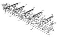
- FIG. 3is a perspective view of box truss including a plurality of video hanger truss bars mounted thereon in accordance with one particular embodiment of the invention.
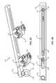
- FIG. 4is a partial perspective view of a video hanger truss bar in use according to one particular embodiment of the invention.
- box trussis meant to encompass those structures known in the art as a box truss, square truss, rectangular truss, tubular truss and/or stage truss, and those terms are used interchangeably herein. Note that other shapes (e.g., triangular, etc.) of truss can additionally be used in connection with the present invention, without limitation.
- the present inventionis directed towards a new and improved adjustable truss hanger 200 that provides a hang point 210 in front of the upper chords 310 of a horizontally oriented box truss 300 .
- the front of the hanger bar 200is defined by the presence of the hanging point 210 , and is oriented towards the audience or front of the stage.
- the hanging point 210is an eyebolt 210 a fixed at one end of the bar 220 made from a solid bar 6061 T-6 aluminum with a nut 210 b .
- the eyebolt 210 ais permanently attached to the bar 220 , by welding and provides a safe and secure connection that supports weights of up to 500 kg (1100 lb.).
- Eyebolt 210 ais oriented to allow quick connection to video rig bars with standard rigging shackles 410 , round slings, or wire rope in order to hang panels 400 in front of the truss 300 (i.e., between the truss and the audience), from the upper chords 310 .
- Mounting bar 220is provided with slots 230 and 240 , to which coupler clamps 250 , 252 are connected.
- the coupler clamps 250 , 252are t-handle half coupler clamps, or other wrap around style coupler clamps, that are designed to fit over the chords 310 of the truss 300 .
- the clamps 250 , 252are made of heavy duty extruded aluminum and are sized to attach to the top of a box truss having 2 inch chords.
- the coupler clamps 250 , 252are adjustable along the slots 230 , 240 , respectively, extending along the longitudinal axis of the bar 220 .
- Each of the slots 230 , 240includes a lip or seat portion 235 , 245 , respectively, which permits the clamp bolts 255 to be at least partially countersunk into the slots 230 , 240 , and provides a surface against which the bolts 255 and/or an intervening washer 257 can be tightened in place.
- Clamp bolts 255can be loosened or tightened using an Allen wrench or other tightening device.
- the slots 230 and 240are of different lengths.
- the front clamp 250allows for adjustment to help with spacing between the backs of video panels or other types of panels and the face of the truss.
- the slot 230allows for 3.5 inches of adjustment to be performed.
- the rear slot 240is sized to permit the rear clamp 252 to adjustably attach to the rear chord of the truss.
- the clamp mounting pointsare adjustable to work with box truss up to 20.5′′ wide.
- the clamps 250 and 252are attached to the front and rear upper chords 310 of the box truss 300 with the bolts 255 loose virtually anywhere on the truss length. This permits the clamps 250 , 252 to slide to the needed spacing to attach to both upper chords at the top of a horizontally oriented box truss. Additionally, the distance between the front chord 310 to the hanging point 210 can be adjusted by moving the bar 220 with the clamp bolts 255 loosened. In the present embodiment, the length of the slot 230 limits the distance between the upper front chord 310 and the hanging point 210 .
- the clamp bolts 255are tightened to ensure that the clamps 250 , 252 are attached to the truss correctly and the clamp t-handles 260 are snugly tightened to grip the upper chords 310 .
- a panel 400can be connected to the hanging point 210 via a shackle 410 or other connector connected between a hanger 420 of the panel 400 and the eyebolt 210 a of the hanging point 210 .
- the panel 400hangs in front of the truss 300 from the hanger bar 200 , which projects as a cantilever from the upper trusses 310 of the truss 300 .
- a series of cantilevered hanger bars 200will be mounted on the upper chords 310 of the truss 300 in order to support an array of panels 400 .
- a plurality of hanger bars 200are used on a single truss 300 to support an entire video wall (i.e., several columns of video panels).
Landscapes
- Engineering & Computer Science (AREA)
- General Engineering & Computer Science (AREA)
- Mechanical Engineering (AREA)
- Mirrors, Picture Frames, Photograph Stands, And Related Fastening Devices (AREA)
Abstract
Description
Claims (14)
Priority Applications (1)
| Application Number | Priority Date | Filing Date | Title |
|---|---|---|---|
| US15/269,280US9995430B2 (en) | 2016-09-19 | 2016-09-19 | Truss hanger |
Applications Claiming Priority (1)
| Application Number | Priority Date | Filing Date | Title |
|---|---|---|---|
| US15/269,280US9995430B2 (en) | 2016-09-19 | 2016-09-19 | Truss hanger |
Publications (2)
| Publication Number | Publication Date |
|---|---|
| US20180080602A1 US20180080602A1 (en) | 2018-03-22 |
| US9995430B2true US9995430B2 (en) | 2018-06-12 |
Family
ID=61618399
Family Applications (1)
| Application Number | Title | Priority Date | Filing Date |
|---|---|---|---|
| US15/269,280ActiveUS9995430B2 (en) | 2016-09-19 | 2016-09-19 | Truss hanger |
Country Status (1)
| Country | Link |
|---|---|
| US (1) | US9995430B2 (en) |
Cited By (4)
| Publication number | Priority date | Publication date | Assignee | Title |
|---|---|---|---|---|
| US20210310601A1 (en)* | 2020-04-02 | 2021-10-07 | Dead On Industries LLC | Binocular/tripod adapter system |
| US11333297B2 (en)* | 2017-11-20 | 2022-05-17 | Willy BRUYNINCKX | Device for strengthening and rigging trusses and method in which such device is applied |
| US11380227B2 (en) | 2020-06-30 | 2022-07-05 | Christie Digital Systems Usa, Inc. | Truss system for video displays |
| US20250075490A1 (en)* | 2023-08-28 | 2025-03-06 | Michael Allen Rasmussen | Hanger assembly for use on open web steel joists or beams |
Families Citing this family (2)
| Publication number | Priority date | Publication date | Assignee | Title |
|---|---|---|---|---|
| CA3001391A1 (en)* | 2018-04-13 | 2019-10-13 | Christie Lites Enterprises Canada Inc. | Truss storage and transport apparatus |
| CN116585721A (en)* | 2023-05-25 | 2023-08-15 | 江苏时代演艺设备有限公司 | Independent feedback type high-precision stage suspender system |
Citations (21)
| Publication number | Priority date | Publication date | Assignee | Title |
|---|---|---|---|---|
| US2470992A (en)* | 1948-01-13 | 1949-05-24 | Harry L Kindorf | Beam clamp for conduit supports |
| US2751175A (en)* | 1952-08-27 | 1956-06-19 | Alfred H Hoblitzell | Pipe hanger clamp |
| US2868485A (en)* | 1955-07-25 | 1959-01-13 | Friel Patrick | I-beam attachment clamp |
| US3664626A (en)* | 1970-07-30 | 1972-05-23 | Valley Decorating Co | Bracket for mounting decorations on a building front |
| US4088079A (en)* | 1976-12-20 | 1978-05-09 | The Cincinnati Butchers' Supply Co. | Combination rail, conveyor chain and return hanger |
| US5085660A (en)* | 1990-11-19 | 1992-02-04 | Lin Kwan C | Innovative locking plate system |
| US5334203A (en)* | 1992-09-30 | 1994-08-02 | Amei Technologies Inc. | Spinal fixation system and methods |
| US5897088A (en)* | 1995-08-01 | 1999-04-27 | Automatic Fire Control, Incorporated | Retaining strap |
| US6287309B1 (en)* | 1997-09-23 | 2001-09-11 | Dimso (Distribution Medicale Du Sudouest) | Screw and plate system for backbone osteosynthesis |
| US6302883B1 (en)* | 1998-10-22 | 2001-10-16 | Depuy Acromed, Inc. | Bone plate-ratcheting compression apparatus |
| US6432108B1 (en)* | 2000-01-24 | 2002-08-13 | Depuy Orthopaedics, Inc. | Transverse connector |
| US6641583B2 (en)* | 2001-03-29 | 2003-11-04 | Endius Incorporated | Apparatus for retaining bone portions in a desired spatial relationship |
| US6962234B1 (en)* | 2002-07-13 | 2005-11-08 | Reeves Eric W | Sliding anchorage device |
| US7069681B2 (en)* | 2004-04-13 | 2006-07-04 | Valmont Industries, Inc. | Sliding sign |
| US20070163834A1 (en)* | 2006-01-03 | 2007-07-19 | D B Industries, Inc. | Slidable beam anchor |
| US7491221B2 (en)* | 2004-03-23 | 2009-02-17 | Stryker Spine | Modular polyaxial bone screw and plate |
| US7608096B2 (en)* | 2003-03-10 | 2009-10-27 | Warsaw Orthopedic, Inc. | Posterior pedicle screw and plate system and methods |
| US8714502B1 (en)* | 2010-07-16 | 2014-05-06 | Joe N. Davis | Bracket assembly |
| US8931747B2 (en)* | 2010-07-16 | 2015-01-13 | Joe N. Davis | Bracket assembly |
| US8950716B2 (en)* | 2011-09-30 | 2015-02-10 | Production Resource Group, Llc | Hoist pickup bar |
| US20150316202A1 (en) | 2014-04-29 | 2015-11-05 | Entertainment Structural Products | Truss Adapter for Mounting Objects on Space Frame Truss |
- 2016
- 2016-09-19USUS15/269,280patent/US9995430B2/enactiveActive
Patent Citations (21)
| Publication number | Priority date | Publication date | Assignee | Title |
|---|---|---|---|---|
| US2470992A (en)* | 1948-01-13 | 1949-05-24 | Harry L Kindorf | Beam clamp for conduit supports |
| US2751175A (en)* | 1952-08-27 | 1956-06-19 | Alfred H Hoblitzell | Pipe hanger clamp |
| US2868485A (en)* | 1955-07-25 | 1959-01-13 | Friel Patrick | I-beam attachment clamp |
| US3664626A (en)* | 1970-07-30 | 1972-05-23 | Valley Decorating Co | Bracket for mounting decorations on a building front |
| US4088079A (en)* | 1976-12-20 | 1978-05-09 | The Cincinnati Butchers' Supply Co. | Combination rail, conveyor chain and return hanger |
| US5085660A (en)* | 1990-11-19 | 1992-02-04 | Lin Kwan C | Innovative locking plate system |
| US5334203A (en)* | 1992-09-30 | 1994-08-02 | Amei Technologies Inc. | Spinal fixation system and methods |
| US5897088A (en)* | 1995-08-01 | 1999-04-27 | Automatic Fire Control, Incorporated | Retaining strap |
| US6287309B1 (en)* | 1997-09-23 | 2001-09-11 | Dimso (Distribution Medicale Du Sudouest) | Screw and plate system for backbone osteosynthesis |
| US6302883B1 (en)* | 1998-10-22 | 2001-10-16 | Depuy Acromed, Inc. | Bone plate-ratcheting compression apparatus |
| US6432108B1 (en)* | 2000-01-24 | 2002-08-13 | Depuy Orthopaedics, Inc. | Transverse connector |
| US6641583B2 (en)* | 2001-03-29 | 2003-11-04 | Endius Incorporated | Apparatus for retaining bone portions in a desired spatial relationship |
| US6962234B1 (en)* | 2002-07-13 | 2005-11-08 | Reeves Eric W | Sliding anchorage device |
| US7608096B2 (en)* | 2003-03-10 | 2009-10-27 | Warsaw Orthopedic, Inc. | Posterior pedicle screw and plate system and methods |
| US7491221B2 (en)* | 2004-03-23 | 2009-02-17 | Stryker Spine | Modular polyaxial bone screw and plate |
| US7069681B2 (en)* | 2004-04-13 | 2006-07-04 | Valmont Industries, Inc. | Sliding sign |
| US20070163834A1 (en)* | 2006-01-03 | 2007-07-19 | D B Industries, Inc. | Slidable beam anchor |
| US8714502B1 (en)* | 2010-07-16 | 2014-05-06 | Joe N. Davis | Bracket assembly |
| US8931747B2 (en)* | 2010-07-16 | 2015-01-13 | Joe N. Davis | Bracket assembly |
| US8950716B2 (en)* | 2011-09-30 | 2015-02-10 | Production Resource Group, Llc | Hoist pickup bar |
| US20150316202A1 (en) | 2014-04-29 | 2015-11-05 | Entertainment Structural Products | Truss Adapter for Mounting Objects on Space Frame Truss |
Cited By (6)
| Publication number | Priority date | Publication date | Assignee | Title |
|---|---|---|---|---|
| US11333297B2 (en)* | 2017-11-20 | 2022-05-17 | Willy BRUYNINCKX | Device for strengthening and rigging trusses and method in which such device is applied |
| US20210310601A1 (en)* | 2020-04-02 | 2021-10-07 | Dead On Industries LLC | Binocular/tripod adapter system |
| US11913596B2 (en)* | 2020-04-02 | 2024-02-27 | Preston Owens | Binocular/tripod adapter system |
| US11380227B2 (en) | 2020-06-30 | 2022-07-05 | Christie Digital Systems Usa, Inc. | Truss system for video displays |
| US20250075490A1 (en)* | 2023-08-28 | 2025-03-06 | Michael Allen Rasmussen | Hanger assembly for use on open web steel joists or beams |
| US12371894B2 (en)* | 2023-08-28 | 2025-07-29 | Michael Allen Rasmussen | Hanger assembly for use on open web steel joists or beams |
Also Published As
| Publication number | Publication date |
|---|---|
| US20180080602A1 (en) | 2018-03-22 |
Similar Documents
| Publication | Publication Date | Title |
|---|---|---|
| US9995430B2 (en) | Truss hanger | |
| US6119999A (en) | Picture hanging system | |
| US8356720B2 (en) | Container storage system | |
| US20140138593A1 (en) | Aerial Roller Spacer Apparatus and Associated Methods Thereof | |
| US11221102B2 (en) | Column mounting bracket | |
| US20200248930A1 (en) | Method and apparatus for mounting panels | |
| US20060070967A1 (en) | Overhead attachable storage shelf | |
| CA2523293A1 (en) | Safety restraint system | |
| US20080135691A1 (en) | Securing system | |
| CA2485364C (en) | Curtain suspension device and a method of suspending curtains | |
| JP2010222115A (en) | Tool for fixing safety fence and method for fixing safety fence using the same | |
| US9829033B2 (en) | Double-beam sliding mount for electronic video displays and other items | |
| US3511463A (en) | Support means for a suspended ceiling structure | |
| CN207704832U (en) | It is a kind of to facilitate stretching, extension propaganda frame | |
| JP2011256696A (en) | Mounting metal fitting for ceiling joist | |
| CA2855865C (en) | Equipment mounting bracket for steel truss | |
| JPH1137390A (en) | Wall drawer stand device | |
| US10088135B2 (en) | Mounting base for work light | |
| JP3208253U (en) | Metal rack clamp | |
| JP2005140167A (en) | Hanging tool | |
| JP6239874B2 (en) | Suspension support | |
| CN220537323U (en) | Steel beam clamp for support and hanger | |
| US20100032538A1 (en) | Electrical device hanger | |
| JP6231789B2 (en) | Suspension support | |
| WO2022064165A1 (en) | Universal column bracket |
Legal Events
| Date | Code | Title | Description |
|---|---|---|---|
| AS | Assignment | Owner name:CHAUVET & SONS, LLC, DELAWARE Free format text:ASSIGNMENT OF ASSIGNORS INTEREST;ASSIGNOR:MILLER, WILLIAM K.;REEL/FRAME:039876/0953 Effective date:20160916 | |
| STCF | Information on status: patent grant | Free format text:PATENTED CASE | |
| AS | Assignment | Owner name:ANTARES CAPITAL LP, AS AGENT, ILLINOIS Free format text:SECURITY INTEREST;ASSIGNOR:CHAUVET & SONS, LLC;REEL/FRAME:055882/0140 Effective date:20210409 | |
| MAFP | Maintenance fee payment | Free format text:PAYMENT OF MAINTENANCE FEE, 4TH YR, SMALL ENTITY (ORIGINAL EVENT CODE: M2551); ENTITY STATUS OF PATENT OWNER: SMALL ENTITY Year of fee payment:4 | |
| AS | Assignment | Owner name:CHAUVET & SONS, LLC, FLORIDA Free format text:RELEASE BY SECURED PARTY;ASSIGNOR:ANTARES CAPITAL LP;REEL/FRAME:065500/0421 Effective date:20231108 Owner name:CAPITAL ONE, NATIONAL ASSOCIATION, AS COLLATERAL AGENT, MARYLAND Free format text:SECURITY INTEREST;ASSIGNOR:CHAUVET & SONS, LLC;REEL/FRAME:065493/0849 Effective date:20231108 | |
| MAFP | Maintenance fee payment | Free format text:PAYMENT OF MAINTENANCE FEE, 8TH YR, SMALL ENTITY (ORIGINAL EVENT CODE: M2552); ENTITY STATUS OF PATENT OWNER: SMALL ENTITY Year of fee payment:8 |