US9994239B2 - Vehicle with force-controlled shock absorber (2-pipe shock absorber) - Google Patents
Vehicle with force-controlled shock absorber (2-pipe shock absorber)Download PDFInfo
- Publication number
- US9994239B2 US9994239B2US15/025,969US201415025969AUS9994239B2US 9994239 B2US9994239 B2US 9994239B2US 201415025969 AUS201415025969 AUS 201415025969AUS 9994239 B2US9994239 B2US 9994239B2
- Authority
- US
- United States
- Prior art keywords
- inner pipe
- working medium
- piston
- shock absorber
- valve arrangement
- Prior art date
- Legal status (The legal status is an assumption and is not a legal conclusion. Google has not performed a legal analysis and makes no representation as to the accuracy of the status listed.)
- Active, expires
Links
- 239000006096absorbing agentSubstances0.000titleclaimsabstractdescription70
- 230000035939shockEffects0.000titleclaimsabstractdescription70
- 230000000630rising effectEffects0.000claimsdescription13
- 238000013016dampingMethods0.000description14
- 239000000725suspensionSubstances0.000description5
- 230000008901benefitEffects0.000description4
- 230000007423decreaseEffects0.000description2
- 230000001419dependent effectEffects0.000description2
- 238000002955isolationMethods0.000description1
- 238000000034methodMethods0.000description1
- 230000002441reversible effectEffects0.000description1
Images


Classifications
- B—PERFORMING OPERATIONS; TRANSPORTING
- B61—RAILWAYS
- B61D—BODY DETAILS OR KINDS OF RAILWAY VEHICLES
- B61D33/00—Seats
- B61D33/0057—Seats characterised by their mounting in vehicles
- B61D33/0078—Seats characterised by their mounting in vehicles adjustably mounted
- B—PERFORMING OPERATIONS; TRANSPORTING
- B60—VEHICLES IN GENERAL
- B60G—VEHICLE SUSPENSION ARRANGEMENTS
- B60G13/00—Resilient suspensions characterised by arrangement, location or type of vibration dampers
- B—PERFORMING OPERATIONS; TRANSPORTING
- B60—VEHICLES IN GENERAL
- B60G—VEHICLE SUSPENSION ARRANGEMENTS
- B60G13/00—Resilient suspensions characterised by arrangement, location or type of vibration dampers
- B60G13/02—Resilient suspensions characterised by arrangement, location or type of vibration dampers having dampers dissipating energy, e.g. frictionally
- B60G13/06—Resilient suspensions characterised by arrangement, location or type of vibration dampers having dampers dissipating energy, e.g. frictionally of fluid type
- B60G13/08—Resilient suspensions characterised by arrangement, location or type of vibration dampers having dampers dissipating energy, e.g. frictionally of fluid type hydraulic
- B—PERFORMING OPERATIONS; TRANSPORTING
- B60—VEHICLES IN GENERAL
- B60G—VEHICLE SUSPENSION ARRANGEMENTS
- B60G17/00—Resilient suspensions having means for adjusting the spring or vibration-damper characteristics, for regulating the distance between a supporting surface and a sprung part of vehicle or for locking suspension during use to meet varying vehicular or surface conditions, e.g. due to speed or load
- B60G17/06—Characteristics of dampers, e.g. mechanical dampers
- B60G17/08—Characteristics of fluid dampers
- B—PERFORMING OPERATIONS; TRANSPORTING
- B60—VEHICLES IN GENERAL
- B60G—VEHICLE SUSPENSION ARRANGEMENTS
- B60G99/00—Subject matter not provided for in other groups of this subclass
- B60G99/002—Suspension details of the suspension of the vehicle body on the vehicle chassis
- B—PERFORMING OPERATIONS; TRANSPORTING
- B60—VEHICLES IN GENERAL
- B60N—SEATS SPECIALLY ADAPTED FOR VEHICLES; VEHICLE PASSENGER ACCOMMODATION NOT OTHERWISE PROVIDED FOR
- B60N2/00—Seats specially adapted for vehicles; Arrangement or mounting of seats in vehicles
- B60N2/50—Seat suspension devices
- B60N2/505—Adjustable suspension including height adjustment
- B—PERFORMING OPERATIONS; TRANSPORTING
- B60—VEHICLES IN GENERAL
- B60N—SEATS SPECIALLY ADAPTED FOR VEHICLES; VEHICLE PASSENGER ACCOMMODATION NOT OTHERWISE PROVIDED FOR
- B60N2/00—Seats specially adapted for vehicles; Arrangement or mounting of seats in vehicles
- B60N2/50—Seat suspension devices
- B60N2/506—Seat guided by rods
- B60N2/508—Scissors-like structure
- B—PERFORMING OPERATIONS; TRANSPORTING
- B60—VEHICLES IN GENERAL
- B60N—SEATS SPECIALLY ADAPTED FOR VEHICLES; VEHICLE PASSENGER ACCOMMODATION NOT OTHERWISE PROVIDED FOR
- B60N2/00—Seats specially adapted for vehicles; Arrangement or mounting of seats in vehicles
- B60N2/50—Seat suspension devices
- B60N2/52—Seat suspension devices using fluid means
- B60N2/522—Seat suspension devices using fluid means characterised by dampening means
- B—PERFORMING OPERATIONS; TRANSPORTING
- B60—VEHICLES IN GENERAL
- B60N—SEATS SPECIALLY ADAPTED FOR VEHICLES; VEHICLE PASSENGER ACCOMMODATION NOT OTHERWISE PROVIDED FOR
- B60N2/00—Seats specially adapted for vehicles; Arrangement or mounting of seats in vehicles
- B60N2/50—Seat suspension devices
- B60N2/52—Seat suspension devices using fluid means
- B60N2/527—Seat suspension devices using fluid means using liquids
- B—PERFORMING OPERATIONS; TRANSPORTING
- B61—RAILWAYS
- B61F—RAIL VEHICLE SUSPENSIONS, e.g. UNDERFRAMES, BOGIES OR ARRANGEMENTS OF WHEEL AXLES; RAIL VEHICLES FOR USE ON TRACKS OF DIFFERENT WIDTH; PREVENTING DERAILING OF RAIL VEHICLES; WHEEL GUARDS, OBSTRUCTION REMOVERS OR THE LIKE FOR RAIL VEHICLES
- B61F5/00—Constructional details of bogies; Connections between bogies and vehicle underframes; Arrangements or devices for adjusting or allowing self-adjustment of wheel axles or bogies when rounding curves
- B61F5/26—Mounting or securing axle-boxes in vehicle or bogie underframes
- B61F5/30—Axle-boxes mounted for movement under spring control in vehicle or bogie underframes
- B61F5/308—Axle-boxes mounted for movement under spring control in vehicle or bogie underframes incorporating damping devices
- B—PERFORMING OPERATIONS; TRANSPORTING
- B61—RAILWAYS
- B61F—RAIL VEHICLE SUSPENSIONS, e.g. UNDERFRAMES, BOGIES OR ARRANGEMENTS OF WHEEL AXLES; RAIL VEHICLES FOR USE ON TRACKS OF DIFFERENT WIDTH; PREVENTING DERAILING OF RAIL VEHICLES; WHEEL GUARDS, OBSTRUCTION REMOVERS OR THE LIKE FOR RAIL VEHICLES
- B61F5/00—Constructional details of bogies; Connections between bogies and vehicle underframes; Arrangements or devices for adjusting or allowing self-adjustment of wheel axles or bogies when rounding curves
- B61F5/50—Other details
- B—PERFORMING OPERATIONS; TRANSPORTING
- B62—LAND VEHICLES FOR TRAVELLING OTHERWISE THAN ON RAILS
- B62D—MOTOR VEHICLES; TRAILERS
- B62D33/00—Superstructures for load-carrying vehicles
- B62D33/06—Drivers' cabs
- B62D33/0604—Cabs insulated against vibrations or noise, e.g. with elastic suspension
- F—MECHANICAL ENGINEERING; LIGHTING; HEATING; WEAPONS; BLASTING
- F16—ENGINEERING ELEMENTS AND UNITS; GENERAL MEASURES FOR PRODUCING AND MAINTAINING EFFECTIVE FUNCTIONING OF MACHINES OR INSTALLATIONS; THERMAL INSULATION IN GENERAL
- F16F—SPRINGS; SHOCK-ABSORBERS; MEANS FOR DAMPING VIBRATION
- F16F9/00—Springs, vibration-dampers, shock-absorbers, or similarly-constructed movement-dampers using a fluid or the equivalent as damping medium
- F16F9/10—Springs, vibration-dampers, shock-absorbers, or similarly-constructed movement-dampers using a fluid or the equivalent as damping medium using liquid only; using a fluid of which the nature is immaterial
- F16F9/14—Devices with one or more members, e.g. pistons, vanes, moving to and fro in chambers and using throttling effect
- F16F9/16—Devices with one or more members, e.g. pistons, vanes, moving to and fro in chambers and using throttling effect involving only straight-line movement of the effective parts
- F16F9/18—Devices with one or more members, e.g. pistons, vanes, moving to and fro in chambers and using throttling effect involving only straight-line movement of the effective parts with a closed cylinder and a piston separating two or more working spaces therein
- F16F9/185—Bitubular units
- F16F9/187—Bitubular units with uni-directional flow of damping fluid through the valves
- F—MECHANICAL ENGINEERING; LIGHTING; HEATING; WEAPONS; BLASTING
- F16—ENGINEERING ELEMENTS AND UNITS; GENERAL MEASURES FOR PRODUCING AND MAINTAINING EFFECTIVE FUNCTIONING OF MACHINES OR INSTALLATIONS; THERMAL INSULATION IN GENERAL
- F16F—SPRINGS; SHOCK-ABSORBERS; MEANS FOR DAMPING VIBRATION
- F16F9/00—Springs, vibration-dampers, shock-absorbers, or similarly-constructed movement-dampers using a fluid or the equivalent as damping medium
- F16F9/32—Details
- F16F9/44—Means on or in the damper for manual or non-automatic adjustment; such means combined with temperature correction
- F16F9/46—Means on or in the damper for manual or non-automatic adjustment; such means combined with temperature correction allowing control from a distance, i.e. location of means for control input being remote from site of valves, e.g. on damper external wall
- B—PERFORMING OPERATIONS; TRANSPORTING
- B60—VEHICLES IN GENERAL
- B60G—VEHICLE SUSPENSION ARRANGEMENTS
- B60G2202/00—Indexing codes relating to the type of spring, damper or actuator
- B60G2202/20—Type of damper
- B60G2202/24—Fluid damper
- B—PERFORMING OPERATIONS; TRANSPORTING
- B60—VEHICLES IN GENERAL
- B60G—VEHICLE SUSPENSION ARRANGEMENTS
- B60G2202/00—Indexing codes relating to the type of spring, damper or actuator
- B60G2202/40—Type of actuator
- B60G2202/41—Fluid actuator
- B60G2202/413—Hydraulic actuator
- B—PERFORMING OPERATIONS; TRANSPORTING
- B60—VEHICLES IN GENERAL
- B60G—VEHICLE SUSPENSION ARRANGEMENTS
- B60G2202/00—Indexing codes relating to the type of spring, damper or actuator
- B60G2202/40—Type of actuator
- B60G2202/41—Fluid actuator
- B60G2202/416—Fluid actuator using a pump, e.g. in the line connecting the lower chamber to the upper chamber of the actuator
- B—PERFORMING OPERATIONS; TRANSPORTING
- B60—VEHICLES IN GENERAL
- B60G—VEHICLE SUSPENSION ARRANGEMENTS
- B60G2500/00—Indexing codes relating to the regulated action or device
- B60G2500/10—Damping action or damper
- B—PERFORMING OPERATIONS; TRANSPORTING
- B60—VEHICLES IN GENERAL
- B60G—VEHICLE SUSPENSION ARRANGEMENTS
- B60G2500/00—Indexing codes relating to the regulated action or device
- B60G2500/10—Damping action or damper
- B60G2500/11—Damping valves
- B—PERFORMING OPERATIONS; TRANSPORTING
- B60—VEHICLES IN GENERAL
- B60G—VEHICLE SUSPENSION ARRANGEMENTS
- B60G2500/00—Indexing codes relating to the regulated action or device
- B60G2500/30—Height or ground clearance
Definitions
- the inventionrelates to a shock absorber.
- FIG. 1A shock absorber of this kind is shown by way of example in FIG. 1 .
- This shock absorberaccording to the prior art comprises a housing having an inner pipe arranged thereon, a piston rod plunging into the inner pipe, a piston being arranged on the end of said piston rod that plunges into the inner pipe, which piston divides the inside of the inner pipe into a lower chamber and an upper chamber.
- a valve arrangementis arranged on the piston, by means of which a working medium received in the inner pipe can flow out of the lower chamber into the upper chamber and vice versa when the piston is moved in the inner pipe.
- a second valve arrangementis arranged at the upper end of the inner pipe, by means of which, when the piston is moved in the inner pipe, the working medium received in the inner pipe can flow out of the upper chamber only into the inside of the housing serving as a tank for the working medium.
- the inner pipehas a third valve arrangement at its lower end, by means of which the working medium received in the inside of the housing serving as a tank can flow only into the lower chamber of the inner pipe when the piston is moved in the inner pipe.
- 2-pipe shock absorbers of this kindare usually called 2-pipe shock absorbers.
- 2-pipe shock absorbers of this kindare used as passive shock absorbers, both as non-adjustable shock absorbers and as adjustable shock absorbers.
- Adjustable 2-pipe shock absorbersare used when the work to be achieved by the shock absorber is to be adapted to corresponding vehicle states of a vehicle, in which an adjustable 2-pipe shock absorber of this kind is fitted, or to the sprung masses of different sizes.
- thisis achieved in that the flow resistance can be modified by means of a variable valve hole in the valve arrangement arranged on the piston between the upper and the lower chamber of the inner pipe of the damper.
- a further feature of passive dampers that are operated in a non-adjustable manneris that the amount of oil exchanged during a defined working stroke is always the same.
- the flow resistanceis dependent only on the speed of the piston inside the inner pipe.
- the flow resistanceis influenced by the change in the valve cross section of the valve arrangement in the piston, in addition to the speed of the piston.
- the amount of oil exchangedis likewise the same for a defined stroke.
- the pistonmoves downwards in the inner pipe so that the lower chamber of the inner pipe decreases in volume, whilst the upper chamber of the inner pipe increases in volume.
- a certain amount of oilfunctioning here as the working medium, is channeled from the lower chamber into the upper chamber via the valve arrangement of the piston, a defined flow resistance thus being generated across the valve arrangement of the piston by means of the speed thereof.
- the amount of oil in the upper chamber of the inner pipe that is additionally displaced in the process by the plunging of the piston rodis channeled off into the housing serving as a tank for the working medium or oil respectively via the valve arrangement arranged at upper end of the inner pipe.
- the pistonmoves upwards inside the inner pipe, reducing the volume of the upper chamber and increasing the volume of the lower chamber, the amount of oil or working medium to be exchanged respectively being channeled from the upper chamber into the inside of the housing serving as a tank for the working medium or into the oil sump there respectively via the valve arrangement at the upper end of the inner pipe.
- the difference in the amount of oil or working medium respectively which is required due to the withdrawal of the piston rodis drawn from the inside of the housing serving as a tank for the working medium or from the oil sump there respectively via the valve arrangement arranged at the bottom of the inner pipe.
- the working medium or oilrespectively moves in a circuit inside the damper.
- the object of the inventionis therefore that of providing a shock absorber of the type mentioned at the outset, by means of which different intended uses can be realised.
- shock absorberhaving the features of claim 1 .
- Advantageous embodiments of the shock absorber according to the inventioncan be found in the dependent claims.
- the shock absorber according to the inventionalso comprises the features that a hydraulic pump drive is arranged between a first connection element of the lower chamber of the inner pipe and a second connection element at the upper chamber of the inner pipe.
- shock absorberBy means of the embodiment of the shock absorber according to the invention it is now possible to operate the shock absorber according to the invention in a passive adjustable manner, an active adjustable manner, a semi-active adjustable manner and, by appropriately controlling the hydraulic pump drive, to adaptively operate the control of the flow resistance of the working medium in the valve arrangement of the piston.
- a hydraulic pump drive of this kindwhen moving the piston in the inner pipe in a defined manner, exchanged amounts of working medium or oil respectively can be increased and/or reduced.
- an embodiment of this kindcan be used for a seat, in particular for a driver's seat of a rail vehicle, for correcting the seat height or alternatively for temporary adjustment.
- Shock absorbers of this kind according to the inventioncan be used not only in wheel suspensions and suspension struts for various vehicles, but rather can also be used to damp vibrations of seats, in particular of sprung vehicle seats and sprung cabs.
- a combination of damping a cab suspension and sprung vehicle seats, for example of a rail vehicleis conceivable.
- the use of the shock absorbers according to the inventionrestricted to uses of this kind, but rather can be used in all possible devices in which a corresponding damping of vibrations is desirable.
- a hydraulic pump drivein combination with a valve arrangement, in particular a solenoid valve or a proportional flow control valve, as a device for controlling the flow resistance of the working medium in the valve arrangement of the piston.
- a valve arrangementin particular a solenoid valve or a proportional flow control valve
- a solenoid valvemakes it possible, for example, to additionally easily achieve two types of damping of the damper in addition to the level control by means of the hydraulic pump drive.
- thiswould be a hard damping, in which the solenoid valve is closed so that the shock absorber according to the invention is still operated as a passive non-adjustable shock absorber.
- an additional working medium exchange or oil exchangerespectively can take place between the upper chamber of the inner pipe and the lower chamber of the inner pipe, so that the flow speed of the working medium is modified by the valve arrangement of the piston and thus softer damping takes place.
- the shock absorberis thus operated in a passive, non-adjustable manner even when the solenoid valve is open.
- the hydraulic pump drivecomprises a controllable pump and a motor for the pump.
- a leakage pipe for the working mediumis provided between the housing serving as a tank for the working medium and the hydraulic pump drive, in particular the controllable pump.
- a leakage pipe of this kindmakes it possible for the working medium or oil respectively from the pump to be returned to the tank so that the working medium consumption or oil consumption respectively of the shock absorber according to the invention is reduced and pollution is prevented.
- controllable pumpmakes it possible for the pressure stage (when retracting the piston into the shock absorber) and the tension stage (when withdrawing the piston from the shock absorber) to be both separately and synchronously adjustable.
- a feed line for the working mediumcan be provided between the housing serving as a tank for the working medium and the lower pressure line and/or the upper pressure line.
- said feed linecan be separated from the lower pressure line and/or the upper pressure line by means of non-return valves.
- control valvescan also be provided, by means of which the flow and thus the pressure compensation can be controlled.
- a rising pipeto be arranged at the upper end of the inner pipe, which rising pipe protrudes into the working medium or oil received in the housing or into the working medium sump or oil sump respectively and by means of which the working medium or oil respectively can be transferred out of the housing serving as a tank into the upper chamber of the inner pipe.
- Said rising pipeis used in particular to ensure that no cavitation occurs during external operation, in which the amount of working medium or amount of oil respectively can be exchanged between the lower chamber 3 and the upper chamber 4 by means of a hydraulic pump.
- the rising pipeensures a closed oil circuit even when a hydraulic pump is connected to the connection elements of the upper and lower chambers.
- FIG. 1shows a shock absorber according to the prior art
- FIG. 2shows a first embodiment example of a shock absorber according to the invention
- FIG. 3shows a second embodiment example of a shock absorber according to the invention
- FIG. 4shows a third embodiment example of a shock absorber according to the invention
- FIG. 5shows a fourth embodiment example of a shock absorber according to the invention.
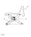
- FIG. 6shows a vehicle seat equipped with a suspension, in which a shock absorber according to the invention is fitted.
- FIG. 2shows a first embodiment example of a shock absorber according to the invention.
- the shock absorberbasically consists of a housing 1 , which is tubular and in which an inner pipe 2 (not shown here) arranged inside the housing ( 1 ) is arranged so as to be stationary.
- the inside of the housing ( 1 )is formed in principle like that of the prior art according to FIG. 1 .
- a piston 5can be moved backwards and forwards in the inner pipe 2 by means of a piston rod 6 , the inner pipe being separated by the piston 5 into an upper chamber 4 and a lower chamber 3 .
- the inner pipe 2is completely filled with a working medium, preferably with an oil.
- a first valve arrangement 9is mounted in the piston 5 .
- Said valve arrangement 9is designed so that the oil can pass through it in both directions. Since additional oil is displaced when moving the piston 5 in the inner pipe 2 from top to bottom by means of the piston rod 6 , the oil must have the opportunity to escape out of the upper chamber 4 .
- a second valve arrangement 8is provided at the upper end of the inner pipe 2 , by means of which valve arrangement oil can escape out of the upper chamber into the container 1 serving as a tank.
- the valve arrangement 8is designed only to allow oil to pass in this direction. It is not possible for oil to pass from the container 1 into the upper chamber 4 of the inner pipe 2 via the valve arrangement 8 .
- a third valve arrangement 7is provided at the lower end of the inner pipe 2 . It is thus possible for oil to enter into the lower chamber 3 of the inner pipe 2 from the container 1 in which it is stored, whilst, due to the reduced volume of the upper chamber 4 , oil found here reaches the container 1 via the valve arrangement 8 .
- this embodiment examplecomprises a connection element 12 on the upper chamber 4 of the inner pipe 2 , and a connection element 13 on the lower chamber 3 of the inner pipe 2 .
- a hydraulic pump driveis connected to the piston 5 as a device for controlling the flow resistance of the working medium or oil in the valve arrangement 9 respectively.
- the hydraulic pump driveconsists of a controllable pump 15 and a pump motor 16 .
- the pump 15is reversible so that it can pump oil out of the lower chamber 3 into the upper chamber 4 of the inner pipe 2 as well as in the opposite direction.
- a pump 15 of this kindfor a defined stroke of the piston 5 inside the inner pipe 2 , amounts of oil exchanged between the lower chamber 3 and the upper chamber 4 can be increased or reduced respectively.
- thiscauses the damping forces to be increased/reduced in response to the introduction of the oil; on the other hand, a height correction, in particular a seat height correction can take place in this embodiment example when a damper of this kind is used on a seat, or a temporary adjustment of the shock absorber can be generally carried out.
- a leakage pipe 21is also provided in the embodiment examples according to FIGS. 2 to 5 , by means of which oil escaping from the pump 15 can be returned into housing 1 serving as a tank for the oil.
- FIGS. 4 and 5comprise a feed line 20 , by means of which the pump 15 can be supplied with any necessary amount of feed oil during operation.
- said feed line 20comprises connections to the pressure lines 17 and 18 , said pressure lines being separated from one another by means of non-return valves or control valves 19 respectively which are used for flow rate compensation or pressure compensation respectively.
- FIG. 5shows a further embodiment example of a shock absorber according to the invention.
- a proportional flow control valveis provided here in parallel with said pump drive on the pressure lines 17 and 18 as a device for controlling the flow resistance of the working medium in the valve arrangement 9 of the piston 5 , which proportional flow control valve is arranged between a pressure line 18 connected at the lower connection element 13 and a pressure line 17 connected at the upper connection element 14 .
- a proportional flow control valve 22 of this kindit is possible to control the flow resistance of the oil therein according to the flow strength. In this respect it is hereby possible to adjust the performance of the shock absorber and thus the damping according to the required loading conditions by means of said proportional flow control valve 22 .
- a passive default setting of the shock absorberis provided here as a hard setting, the shock absorber achieving its highest performance in this flowless state.
- the proportional flow control valve 22When the proportional flow control valve 22 is activated, the damping forces are reduced, since a certain proportion of the oil exchange between the chamber 3 and the chamber 4 is diverted through the pressure lines 17 and 18 and the proportional flow control valve 22 , without flowing through the hydraulic pump arrangement. The stronger the flow, the more oil can flow through the proportional flow control valve, so that the shock absorber is adjusted to be softer as the flow strength increases.
- the shock absorbercan therefore be operated both semi-actively and passively.
- all the embodiment examples in FIGS. 2 to 5comprise a rising pipe 14 arranged on the upper end of the inner pipe 2 , which rising pipe protrudes through an oil sump level 11 into the oil sump 10 inside the container 1 .
- Said rising line 14is used to ensure that no cavitation occurs during external operation of the shock absorber, in which the amount of oil is exchanged between the lower chamber 3 and the upper chamber 4 by means of a hydraulic pump. Cavitation of this kind would be disadvantageous for the operation of the shock absorber.
- said rising pipe 14ensures a closed oil circuit even during external operation.
- a vehicle seat 30is shown in FIG. 6 , which has suspension 32 , the vibrations of which are damped by means of a shock absorber 31 according to the invention.
Landscapes
- Engineering & Computer Science (AREA)
- Mechanical Engineering (AREA)
- Transportation (AREA)
- General Engineering & Computer Science (AREA)
- Aviation & Aerospace Engineering (AREA)
- Chemical & Material Sciences (AREA)
- Combustion & Propulsion (AREA)
- Fluid-Damping Devices (AREA)
- Vehicle Body Suspensions (AREA)
- Actuator (AREA)
Abstract
Description
This application is a national stage application under 35 U.S.C. 371 and claims the benefit of PCT Application No. PCT/EP2014/070495 having an international filing date of 25 Sep. 2014, which designated the United States, which PCT application claimed the benefit of German Patent Application No. 10 2013 110 920.9 filed 1 Oct. 2013, the disclosures of each of which are incorporated herein by reference in their entirety.
The invention relates to a shock absorber.
A shock absorber of this kind is shown by way of example inFIG. 1 . This shock absorber according to the prior art comprises a housing having an inner pipe arranged thereon, a piston rod plunging into the inner pipe, a piston being arranged on the end of said piston rod that plunges into the inner pipe, which piston divides the inside of the inner pipe into a lower chamber and an upper chamber. In this case, a valve arrangement is arranged on the piston, by means of which a working medium received in the inner pipe can flow out of the lower chamber into the upper chamber and vice versa when the piston is moved in the inner pipe. A second valve arrangement is arranged at the upper end of the inner pipe, by means of which, when the piston is moved in the inner pipe, the working medium received in the inner pipe can flow out of the upper chamber only into the inside of the housing serving as a tank for the working medium. Lastly, the inner pipe has a third valve arrangement at its lower end, by means of which the working medium received in the inside of the housing serving as a tank can flow only into the lower chamber of the inner pipe when the piston is moved in the inner pipe.
Shock absorbers of this kind according to prior art are usually called 2-pipe shock absorbers. 2-pipe shock absorbers of this kind are used as passive shock absorbers, both as non-adjustable shock absorbers and as adjustable shock absorbers.
In the case of a non-adjustable 2-pipe shock absorber, the properties of the damper or of the damping are clearly defined in such a way that the flow resistance of the working medium is set by the valve arrangements used in the damper.
Adjustable 2-pipe shock absorbers are used when the work to be achieved by the shock absorber is to be adapted to corresponding vehicle states of a vehicle, in which an adjustable 2-pipe shock absorber of this kind is fitted, or to the sprung masses of different sizes. In the case of passive, hydraulically adjustable 2-pipe shock absorbers of this kind, this is achieved in that the flow resistance can be modified by means of a variable valve hole in the valve arrangement arranged on the piston between the upper and the lower chamber of the inner pipe of the damper.
A further feature of passive dampers that are operated in a non-adjustable manner is that the amount of oil exchanged during a defined working stroke is always the same. The flow resistance is dependent only on the speed of the piston inside the inner pipe.
In the case of adjustably operated passive dampers, when the stroke is likewise defined the same, the flow resistance is influenced by the change in the valve cross section of the valve arrangement in the piston, in addition to the speed of the piston. The amount of oil exchanged is likewise the same for a defined stroke.
The mode of operation of a 2-pipe shock absorber of this kind according to the prior art is briefly described below.
When the damper is retracted, the piston moves downwards in the inner pipe so that the lower chamber of the inner pipe decreases in volume, whilst the upper chamber of the inner pipe increases in volume. During this retraction of the damper, a certain amount of oil, functioning here as the working medium, is channeled from the lower chamber into the upper chamber via the valve arrangement of the piston, a defined flow resistance thus being generated across the valve arrangement of the piston by means of the speed thereof. The amount of oil in the upper chamber of the inner pipe that is additionally displaced in the process by the plunging of the piston rod is channeled off into the housing serving as a tank for the working medium or oil respectively via the valve arrangement arranged at upper end of the inner pipe.
If the damper is now withdrawn, the piston moves upwards inside the inner pipe, reducing the volume of the upper chamber and increasing the volume of the lower chamber, the amount of oil or working medium to be exchanged respectively being channeled from the upper chamber into the inside of the housing serving as a tank for the working medium or into the oil sump there respectively via the valve arrangement at the upper end of the inner pipe. The difference in the amount of oil or working medium respectively which is required due to the withdrawal of the piston rod is drawn from the inside of the housing serving as a tank for the working medium or from the oil sump there respectively via the valve arrangement arranged at the bottom of the inner pipe.
As already explained, the working medium or oil respectively moves in a circuit inside the damper.
Since a 2-pipe shock absorber of this kind must be appropriately preassembled according to its use (passive adjustable or passive non-adjustable), it is not possible to use a damper provided in one case for another intended use.
The object of the invention is therefore that of providing a shock absorber of the type mentioned at the outset, by means of which different intended uses can be realised.
This object is achieved by a shock absorber having the features ofclaim 1. Advantageous embodiments of the shock absorber according to the invention can be found in the dependent claims.
In addition to the features in the preamble ofclaim 1, the shock absorber according to the invention also comprises the features that a hydraulic pump drive is arranged between a first connection element of the lower chamber of the inner pipe and a second connection element at the upper chamber of the inner pipe.
By means of the embodiment of the shock absorber according to the invention it is now possible to operate the shock absorber according to the invention in a passive adjustable manner, an active adjustable manner, a semi-active adjustable manner and, by appropriately controlling the hydraulic pump drive, to adaptively operate the control of the flow resistance of the working medium in the valve arrangement of the piston. By means of a hydraulic pump drive of this kind, when moving the piston in the inner pipe in a defined manner, exchanged amounts of working medium or oil respectively can be increased and/or reduced. As a result of this embodiment, it is possible to achieve a level control of the shock absorber in addition to increasing or lowering the damping forces respectively. In particular, an embodiment of this kind can be used for a seat, in particular for a driver's seat of a rail vehicle, for correcting the seat height or alternatively for temporary adjustment.
Shock absorbers of this kind according to the invention can be used not only in wheel suspensions and suspension struts for various vehicles, but rather can also be used to damp vibrations of seats, in particular of sprung vehicle seats and sprung cabs. In addition, a combination of damping a cab suspension and sprung vehicle seats, for example of a rail vehicle, is conceivable. Nor is the use of the shock absorbers according to the invention restricted to uses of this kind, but rather can be used in all possible devices in which a corresponding damping of vibrations is desirable.
Of course, it is also possible to provide a hydraulic pump drive in combination with a valve arrangement, in particular a solenoid valve or a proportional flow control valve, as a device for controlling the flow resistance of the working medium in the valve arrangement of the piston. The advantages and applications described above for the individual devices can thus be used in combination.
Using a solenoid valve makes it possible, for example, to additionally easily achieve two types of damping of the damper in addition to the level control by means of the hydraulic pump drive. In one case, this would be a hard damping, in which the solenoid valve is closed so that the shock absorber according to the invention is still operated as a passive non-adjustable shock absorber. If the solenoid valve is opened, an additional working medium exchange or oil exchange respectively can take place between the upper chamber of the inner pipe and the lower chamber of the inner pipe, so that the flow speed of the working medium is modified by the valve arrangement of the piston and thus softer damping takes place. The shock absorber is thus operated in a passive, non-adjustable manner even when the solenoid valve is open. However, it is possible to switch between hard and soft damping owing to the two possible settings “solenoid valve closed” and “solenoid valve open”.
By using a proportional flow valve, it is possible to continuously vary the flow speed in the pressure lines between the upper connection element and the proportional flow control valve and between the lower pressure line and the proportional flow control valve between the completely closed and completely open states of the proportional flow control valve. Adjustable, continuous damping is thus possible, by means of which it is possible to select not only between hard and soft damping, but also between all damping values therebetween.
Furthermore, it has been found to be advantageous for the hydraulic pump drive to comprise a controllable pump and a motor for the pump.
Since, when operating a pump, it is also always necessary to take into account corresponding leakages, in particular when working at high pressures, a leakage pipe for the working medium is provided between the housing serving as a tank for the working medium and the hydraulic pump drive, in particular the controllable pump. A leakage pipe of this kind makes it possible for the working medium or oil respectively from the pump to be returned to the tank so that the working medium consumption or oil consumption respectively of the shock absorber according to the invention is reduced and pollution is prevented.
In particular the use of a controllable pump makes it possible for the pressure stage (when retracting the piston into the shock absorber) and the tension stage (when withdrawing the piston from the shock absorber) to be both separately and synchronously adjustable.
In addition, for pressure compensation, a feed line for the working medium can be provided between the housing serving as a tank for the working medium and the lower pressure line and/or the upper pressure line. In addition, said feed line can be separated from the lower pressure line and/or the upper pressure line by means of non-return valves. However, control valves can also be provided, by means of which the flow and thus the pressure compensation can be controlled.
According to another concept of the invention, it is provided for a rising pipe to be arranged at the upper end of the inner pipe, which rising pipe protrudes into the working medium or oil received in the housing or into the working medium sump or oil sump respectively and by means of which the working medium or oil respectively can be transferred out of the housing serving as a tank into the upper chamber of the inner pipe. Said rising pipe is used in particular to ensure that no cavitation occurs during external operation, in which the amount of working medium or amount of oil respectively can be exchanged between thelower chamber 3 and theupper chamber 4 by means of a hydraulic pump. As a result, the rising pipe ensures a closed oil circuit even when a hydraulic pump is connected to the connection elements of the upper and lower chambers.
Further aims, advantages, features and possible applications of the present invention can be found in the following description of embodiments with reference to the drawings. In this case, all of the features which are described and/or shown in the drawings, in isolation or in any reasonable combination, form the subject matter of the present invention, irrespective of how they are described in the claims and irrespective of the dependency references thereof.
In the drawings:
In contrast to the housing from the prior art according toFIG. 1 , this embodiment example comprises aconnection element 12 on theupper chamber 4 of theinner pipe 2, and aconnection element 13 on thelower chamber 3 of theinner pipe 2.
At theconnection elements piston 5 as a device for controlling the flow resistance of the working medium or oil in thevalve arrangement 9 respectively.
In the present case, the hydraulic pump drive consists of acontrollable pump 15 and apump motor 16. In this case, thepump 15 is reversible so that it can pump oil out of thelower chamber 3 into theupper chamber 4 of theinner pipe 2 as well as in the opposite direction. By means of apump 15 of this kind, for a defined stroke of thepiston 5 inside theinner pipe 2, amounts of oil exchanged between thelower chamber 3 and theupper chamber 4 can be increased or reduced respectively. On the one hand, this causes the damping forces to be increased/reduced in response to the introduction of the oil; on the other hand, a height correction, in particular a seat height correction can take place in this embodiment example when a damper of this kind is used on a seat, or a temporary adjustment of the shock absorber can be generally carried out.
Since a certain leakage rate must also always be taken into account in pump systems, aleakage pipe 21 is also provided in the embodiment examples according toFIGS. 2 to 5 , by means of which oil escaping from thepump 15 can be returned intohousing 1 serving as a tank for the oil.
In addition, the embodiment examples inFIGS. 4 and 5 comprise afeed line 20, by means of which thepump 15 can be supplied with any necessary amount of feed oil during operation. In this case saidfeed line 20 comprises connections to the pressure lines17 and18, said pressure lines being separated from one another by means of non-return valves orcontrol valves 19 respectively which are used for flow rate compensation or pressure compensation respectively.
In addition, all the embodiment examples inFIGS. 2 to 5 comprise a risingpipe 14 arranged on the upper end of theinner pipe 2, which rising pipe protrudes through anoil sump level 11 into theoil sump 10 inside thecontainer 1. Said risingline 14 is used to ensure that no cavitation occurs during external operation of the shock absorber, in which the amount of oil is exchanged between thelower chamber 3 and theupper chamber 4 by means of a hydraulic pump. Cavitation of this kind would be disadvantageous for the operation of the shock absorber. In addition, said risingpipe 14 ensures a closed oil circuit even during external operation.
Avehicle seat 30 is shown inFIG. 6 , which hassuspension 32, the vibrations of which are damped by means of ashock absorber 31 according to the invention.
- 1 Housing
- 2 Inner pipe
- 3 Chamber
- 4 Chamber
- 5 Piston
- 6 Piston rod
- 7 Valve arrangement
- 8 Valve arrangement
- 9 Valve arrangement
- 10 Oil sump
- 11 Oil sump level
- 12 Connection element
- 13 Connection element
- 14 Rising pipe
- 15 Pump
- 16 Motor
- 17 Pressure line
- 18 Pressure line
- 19 Non-return valve
- 20 Feed line
- 21 Leakage pipe
- 22 Proportional flow control valve
Claims (17)
1. A shock absorber comprising:
a) a housing;
b) an inner pipe arranged in the housing;
c) a piston rod that plunges into the inner pipe;
d) a piston arranged on the end of the piston rod that plunges into the inner pipe, which piston divides the inside of the inner pipe into a lower chamber and an upper chamber;
e) a first valve arrangement arranged on the piston, by means of which a working medium received in the inner pipe can flow out of the lower chamber into the upper chamber and vice versa when the piston is moved in the inner pipe;
f) a second valve arrangement arranged at the upper end of the inner pipe, by means of which, when the piston is moved in the inner pipe, the working medium received in the inner pipe can flow out of the upper chamber only into the inside of the housing serving as a tank for the working medium; and
g) a third valve arrangement arranged at the lower end of the inner pipe, by means of which the working medium received in the inside of the housing serving as a tank can flow out of the inside of the housing serving as a tank only into the lower chamber when the piston is moved in the inner pipe,
wherein a hydraulic pump drive is arranged between a first connection element of the lower chamber of the inner pipe and a second connection element at the upper chamber of the inner pipe, and
wherein a leakage pipe for the working medium is provided between the housing serving as a tank for the working medium and the hydraulic pump drive.
2. The shock absorber according toclaim 1 ,
wherein the hydraulic pump drive is connected to the lower and the upper connection element by means of pressure lines.
3. The shock absorber according toclaim 1 ,
wherein a valve arrangement, in particular a solenoid valve or a proportional flow control valve, is provided for controlling the flow resistance of the working medium in the first valve arrangement, said valve arrangement being arranged between a pressure line connected at the lower connection element and a pressure line connected at the upper connection element.
4. The shock absorber according toclaim 1 ,
wherein the hydraulic pump drive comprises a controllable pump and a motor for the pump.
5. The shock absorber according toclaim 2 ,
wherein a feed line for the working medium is provided between the housing serving as a tank for the working medium and at least one of the lower pressure line and the upper pressure line.
6. The shock absorber according toclaim 5 ,
wherein a non-return valve or a control valve respectively is arranged between the feed line and at least one of the lower pressure line and the upper pressure line.
7. The shock absorber according toclaim 1 ,
wherein a rising pipe is arranged at the upper end of the inner pipe, which rising pipe protrudes into the working medium received in the housing and by means of which working medium can be transferred from the housing serving as a tank into the upper chamber of the inner pipe.
8. The shock absorber according toclaim 1 ,
wherein the hydraulic pump drive comprises a controllable pump and a motor for the pump.
9. A shock absorber comprising:
a) a housing;
b) an inner pipe arranged in the housing;
c) a piston rod that plunges into the inner pipe;
d) a piston arranged on the end of the piston rod that plunges into the inner pipe, which piston divides the inside of the inner pipe into a lower chamber and an upper chamber;
e) a first valve arrangement arranged on the piston, by means of which a working medium received in the inner pipe can flow out of the lower chamber into the upper chamber and vice versa when the piston is moved in the inner pipe;
f) a second valve arrangement arranged at the upper end of the inner pipe, by means of which, when the piston is moved in the inner pipe, the working medium received in the inner pipe can flow out of the upper chamber only into the inside of the housing serving as a tank for the working medium; and
g) a third valve arrangement arranged at the lower end of the inner pipe, by means of which the working medium received in the inside of the housing serving as a tank can flow out of the inside of the housing serving as a tank only into the lower chamber when the piston is moved in the inner pipe,
wherein a hydraulic pump drive is arranged between a first connection element of the lower chamber of the inner pipe and a second connection element at the upper chamber of the inner pipe,
wherein the hydraulic pump drive is connected to the lower and the upper connection element by means of pressure lines, and
wherein a feed line for the working medium is provided between the housing serving as a tank for the working medium and at least one of the lower pressure line and the upper pressure line.
10. The shock absorber according toclaim 9 ,
wherein a non-return valve or a control valve respectively is arranged between the feed line and at least one of the lower pressure line and the upper pressure line.
11. The shock absorber according toclaim 9 ,
wherein a valve arrangement, in particular a solenoid valve or a proportional flow control valve, is provided for controlling the flow resistance of the working medium in the first valve arrangement, said valve arrangement being arranged between a pressure line connected at the lower connection element and a pressure line connected at the upper connection element.
12. A shock absorber comprising:
a) a housing;
b) an inner pipe arranged in the housing;
c) a piston rod that plunges into the inner pipe;
d) a piston arranged on the end of the piston rod that plunges into the inner pipe, which piston divides the inside of the inner pipe into a lower chamber and an upper chamber;
e) a first valve arrangement arranged on the piston, by means of which a working medium received in the inner pipe can flow out of the lower chamber into the upper chamber and vice versa when the piston is moved in the inner pipe;
f) a second valve arrangement arranged at the upper end of the inner pipe, by means of which, when the piston is moved in the inner pipe, the working medium received in the inner pipe can flow out of the upper chamber only into the inside of the housing serving as a tank for the working medium;
g) a third valve arrangement arranged at the lower end of the inner pipe, by means of which the working medium received in the inside of the housing serving as a tank can flow out of the inside of the housing serving as a tank only into the lower chamber when the piston is moved in the inner pipe,
wherein a hydraulic pump drive is arranged between a first connection element of the lower chamber of the inner pipe and a second connection element at the upper chamber of the inner pipe,
wherein a rising pipe is arranged at the upper end of the inner pipe, which rising pipe protrudes into the working medium received in the housing and by means of which working medium can be transferred from the housing serving as a tank into the upper chamber of the inner pipe.
13. The shock absorber according toclaim 12 ,
wherein the hydraulic pump drive is connected to the lower and the upper connection element by means of pressure lines.
14. The shock absorber according toclaim 13 ,
wherein a feed line for the working medium is provided between the housing serving as a tank for the working medium and at least one of the lower pressure line and the upper pressure line.
15. The shock absorber according toclaim 12 ,
wherein a valve arrangement, in particular a solenoid valve or a proportional flow control valve, is provided for controlling the flow resistance of the working medium in the first valve arrangement, said valve arrangement being arranged between a pressure line connected at the lower connection element and a pressure line connected at the upper connection element.
16. The shock absorber according toclaim 12 ,
wherein the hydraulic pump drive comprises a controllable pump and a motor for the pump.
17. The shock absorber according toclaim 12 ,
wherein a non-return valve or a control valve respectively is arranged between the feed line and at least one of the lower pressure line and the upper pressure line.
Applications Claiming Priority (4)
| Application Number | Priority Date | Filing Date | Title |
|---|---|---|---|
| DE102013110920.9ADE102013110920B4 (en) | 2013-10-01 | 2013-10-01 | Vehicle seat with force-controlled damper (2-pipe damper) |
| DE102013110920.9 | 2013-10-01 | ||
| DE102013110920 | 2013-10-01 | ||
| PCT/EP2014/070495WO2015049156A1 (en) | 2013-10-01 | 2014-09-25 | Vehicle with force-controlled shock absorber (2-pipe shock absorber |
Publications (2)
| Publication Number | Publication Date |
|---|---|
| US20160311446A1 US20160311446A1 (en) | 2016-10-27 |
| US9994239B2true US9994239B2 (en) | 2018-06-12 |
Family
ID=51626029
Family Applications (1)
| Application Number | Title | Priority Date | Filing Date |
|---|---|---|---|
| US15/025,969Active2035-01-29US9994239B2 (en) | 2013-10-01 | 2014-09-25 | Vehicle with force-controlled shock absorber (2-pipe shock absorber) |
Country Status (5)
| Country | Link |
|---|---|
| US (1) | US9994239B2 (en) |
| EP (1) | EP3052327B1 (en) |
| CN (1) | CN105579256B (en) |
| DE (1) | DE102013110920B4 (en) |
| WO (1) | WO2015049156A1 (en) |
Cited By (4)
| Publication number | Priority date | Publication date | Assignee | Title |
|---|---|---|---|---|
| US20180058532A1 (en)* | 2016-09-01 | 2018-03-01 | Zf Friedrichshafen Ag | Vibration Damper And Vehicle |
| US11173982B2 (en)* | 2017-08-04 | 2021-11-16 | Joshua J. Angell | Active air spring |
| US20220314725A1 (en)* | 2021-04-02 | 2022-10-06 | Toyota Jidosha Kabushiki Kaisha | Vehicle control device |
| US20230109503A1 (en)* | 2019-03-04 | 2023-04-06 | Kyb Corporation | Shock absorber |
Families Citing this family (10)
| Publication number | Priority date | Publication date | Assignee | Title |
|---|---|---|---|---|
| DE102013110926B4 (en)* | 2013-10-01 | 2019-09-05 | Grammer Aktiengesellschaft | Vehicle seat or vehicle cabin with a suspension device and utility vehicle |
| DE102013110924B4 (en)* | 2013-10-01 | 2018-02-08 | Grammer Ag | Vehicle with force-controlled damper with control valve |
| DE102014109191B8 (en)* | 2014-07-01 | 2018-12-20 | Grammer Aktiengesellschaft | Suspension system for vehicle seats and method for springing vehicle seat parts |
| DE102015218494A1 (en)* | 2015-09-25 | 2017-03-30 | Zf Friedrichshafen Ag | Vibration damper, method for operating a vibration damper, control device and motor vehicle |
| DE102016014779A1 (en) | 2016-12-10 | 2018-06-14 | Hydac Technology Gmbh | Hydropneumatic piston-cylinder arrangement |
| US11110831B2 (en)* | 2019-02-25 | 2021-09-07 | Scott Coffman | Force absorbing vehicle seat mounting system |
| EP3753763B1 (en)* | 2019-06-20 | 2022-10-19 | The Dynamic Engineering Solution Pty Ltd | Vehicle suspension system |
| CN111605444B (en)* | 2020-06-01 | 2021-09-17 | 长沙理工大学 | Working method of induction type automobile seat |
| CN114559782B (en)* | 2022-02-15 | 2023-05-12 | 江苏理工学院 | Integrated semi-active oil-gas suspension structure and control method thereof |
| CN118991568B (en)* | 2024-09-14 | 2025-09-26 | 重庆长安汽车股份有限公司 | Zero-gravity seat system, control method, control device and vehicle thereof |
Citations (153)
| Publication number | Priority date | Publication date | Assignee | Title |
|---|---|---|---|---|
| CH138281A (en) | 1928-04-18 | 1930-02-28 | Wilhelm Knoll Fa | Upholstery on seating and reclining furniture. |
| GB459221A (en)* | 1935-03-30 | 1935-10-01 | Jean Bugatti | Improvements in or relating to hydraulic suspension especially intended for vehicles |
| US2346895A (en) | 1942-05-02 | 1944-04-18 | Bergman Simon | Vehicle seat |
| US2660222A (en) | 1952-05-29 | 1953-11-24 | Leland A Woodsworth | Safety seat for vehicles |
| FR1081491A (en) | 1953-07-21 | 1954-12-20 | Damper | |
| US2725078A (en) | 1951-06-27 | 1955-11-29 | Walter P Glancy | Flexible liner assembly for a fluid pressure device |
| FR1364719A (en) | 1963-05-14 | 1964-06-26 | Improvements made to seats, in particular those mounted on supports subjected to vibrations | |
| US3148869A (en) | 1963-01-29 | 1964-09-15 | Pullman Inc | Hydraulic cushion device |
| US3269774A (en) | 1963-04-04 | 1966-08-30 | Glanzstoff Ag | Movable seat including shock-absorbing means and safety belt |
| DE1287453B (en) | 1966-06-16 | 1969-01-16 | Wilhelm Hermann Mueller & Co K | Air bellows for vehicle suspensions |
| US3470692A (en) | 1967-03-13 | 1969-10-07 | Int Harvester Co | Parallel dual accumulator seat suspension |
| US3480293A (en) | 1966-09-15 | 1969-11-25 | Arthur E Vogel | Control system for vehicle suspensions |
| DE2016973A1 (en) | 1969-04-14 | 1970-10-15 | The Goodyear Tire & Rubber Company, Akron, Ohio (V.St.A.) | Protective part for pneumatic springs |
| GB1295410A (en) | 1970-12-04 | 1972-11-08 | ||
| US3732944A (en) | 1971-04-12 | 1973-05-15 | Menasco Mfg Co | Automatic vacuum restraint apparatus |
| US3806191A (en) | 1971-08-17 | 1974-04-23 | Daimler Benz Ag | Seat in particular co-driver seat in a motor vehicle |
| US3938770A (en) | 1974-10-07 | 1976-02-17 | Caterpillar Tractor Co. | Method and apparatus for hydraulically suspending a vehicle seat |
| US4087069A (en) | 1976-06-23 | 1978-05-02 | Uop Inc. | Suspension system for wide seat |
| US4139186A (en) | 1976-11-26 | 1979-02-13 | Itt Industries, Inc. | Retractable shock absorber |
| DE2756624A1 (en) | 1977-12-19 | 1979-06-21 | Continental Gummi Werke Ag | DIAPHRAGM PISTON |
| DE2757661A1 (en) | 1977-12-23 | 1979-06-28 | Bosch Gmbh Robert | Servo damped support for vehicle seat - is operated by seat load sensor and has automatic damping system |
| DD141769A1 (en) | 1979-01-16 | 1980-05-21 | Klaus Drechsler | VIBRATION-REDUCED DRIVER'S CABIN FOR SELF-OPERATING WORK MACHINES |
| US4418955A (en) | 1980-07-03 | 1983-12-06 | G. L. Rexroth Gmbh | Support unit for a cab in utilitarian vehicles |
| US4497078A (en) | 1983-02-14 | 1985-02-05 | Vogel Jerald M | Apparatus for preventing the transmission of vibrations |
| US4502673A (en) | 1982-02-11 | 1985-03-05 | Applied Power Inc. | Integral shock absorber and spring assembly |
| US4526258A (en) | 1981-09-15 | 1985-07-02 | Luk Lamellen Und Kupplungsbau Gmbh | Fluid-operated clutch disengaging apparatus |
| US4531761A (en) | 1982-05-13 | 1985-07-30 | Dr. Ing. H.C.F. Porsche Aktiengesellschaft | Apparatus for vibration isolation attachment of subframe or aggregate holder |
| DE3517345A1 (en) | 1985-05-14 | 1986-11-20 | Grammer Sitzsysteme GmbH, 8450 Amberg | SUSPENSION DEVICE |
| DE3517505A1 (en) | 1985-05-15 | 1986-11-20 | Grammer Sitzsysteme GmbH, 8450 Amberg | CUSHIONED SEAT |
| JPS6218347A (en) | 1985-07-17 | 1987-01-27 | Yanmar Diesel Engine Co Ltd | Seat suspension structure |
| JPS6218346A (en) | 1985-07-17 | 1987-01-27 | Yanmar Diesel Engine Co Ltd | Sear suspension structure |
| US4655440A (en) | 1984-04-14 | 1987-04-07 | Robert Bosch Gmbh | Apparatus for controlling vehicle spring firmness |
| US4743000A (en) | 1985-04-12 | 1988-05-10 | Robert Bosch Gmbh | Method and apparatus for controlling spring stiffness, in particular in vehicles |
| EP0322608A2 (en) | 1987-12-28 | 1989-07-05 | Toyota Jidosha Kabushiki Kaisha | Shock absorber |
| DE3831724A1 (en) | 1988-09-17 | 1990-03-22 | Maute Geb Hermann Birgit | Coating product and process for its production |
| US4936423A (en) | 1985-04-12 | 1990-06-26 | Robert Bosch Gmbh | Apparatus for damping courses of motion |
| DE3930612A1 (en) | 1989-09-13 | 1991-03-21 | Isringhausen Geb | VEHICLE SEAT |
| US5082309A (en)* | 1988-11-08 | 1992-01-21 | Daimler-Benz Ag | Suspension system for vehicles |
| DE4029490A1 (en) | 1990-09-18 | 1992-03-19 | Boge Ag | Vehicle hydraulic piston-cylinder vibration damper - has secondary piston fitted in guide tube inside main piston rod |
| DE4037289A1 (en) | 1990-11-23 | 1992-05-27 | Rieter Ag Maschf | DEVICE FOR TENSIONING A DRIVE BELT |
| US5169112A (en) | 1991-08-26 | 1992-12-08 | Milsco Manufacturing Company | Electronic suspension vehicle seat |
| DE3686619T2 (en) | 1985-07-31 | 1993-04-29 | Celanese Corp | IMMOBILIZED LIQUID MEMBRANE. |
| US5222759A (en) | 1990-02-27 | 1993-06-29 | Robert Bosch Gmbh | Apparatus for active control of body motions in motor vehicles |
| DE4216987A1 (en) | 1992-01-17 | 1993-07-22 | Bilstein August Gmbh Co Kg | ADJUSTABLE VIBRATION DAMPER FOR MOTOR VEHICLES |
| DE3785493T2 (en) | 1986-05-06 | 1993-10-21 | Du Pont | Ruffled, cellular fiber with cells collapsing in the folds. |
| US5263559A (en) | 1989-09-23 | 1993-11-23 | Robert Bosch Gmbh | Damping system for a shock absorber having a one-way check valve |
| US5273240A (en) | 1991-05-02 | 1993-12-28 | Baruch Sharon | Impact absorption system, particularly for aircraft seats |
| US5290089A (en) | 1992-12-28 | 1994-03-01 | General Motors Corporation | Seat bellows energy absorber |
| US5294085A (en) | 1992-11-10 | 1994-03-15 | Comfort Ridge Usa, Inc. | Shock and vibration isolation apparatus for motor vehicle seats |
| WO1994022692A1 (en) | 1993-03-31 | 1994-10-13 | Mueller Franz | Safety device for vehicles |
| US5538117A (en) | 1994-05-11 | 1996-07-23 | Messier-Bugatti | Safety device for a system transported on board a vehicle, in particular an aircraft |
| US5685603A (en) | 1996-03-05 | 1997-11-11 | Trw Vehicle Safety Systems Inc. | Apparatus with a child seat and an energy absorption mechanism |
| US5836647A (en) | 1997-05-20 | 1998-11-17 | Turman; Ben | Vehicle seat with shock absorption |
| US5871257A (en) | 1997-12-24 | 1999-02-16 | Dundes, Sr.; Kenneth E. | Self-leveling seat |
| US5876085A (en) | 1997-02-27 | 1999-03-02 | Milsco Manufacturing Company | Adjustable vehicle seat |
| WO1999033676A1 (en) | 1997-12-18 | 1999-07-08 | Volvo Lastvagnar Ab | Air spring device for load-carrying vehicles |
| US6120082A (en)* | 1999-03-09 | 2000-09-19 | Navistar International Transportation Corp. | Integrated active seat suspension and seat lockup device |
| DE19938698A1 (en) | 1999-08-14 | 2001-02-15 | Volkswagen Ag | Vehicle seat |
| US20010015565A1 (en) | 1999-12-06 | 2001-08-23 | Yasuki Motozawa | Occupant protective apparatus |
| US20010033047A1 (en) | 2000-04-20 | 2001-10-25 | Mannesmann Sachs Ag | Suspension system for motor vehicles |
| EP1186467A1 (en) | 2000-09-05 | 2002-03-13 | Deere & Company | Hydraulic circuit for active suspension system |
| DE20116588U1 (en) | 2000-12-27 | 2002-05-23 | ASF THOMAS INDUSTRIES GMBH, 87700 Memmingen | measuring device |
| US20020145315A1 (en) | 2000-10-25 | 2002-10-10 | Fraley Gregory S. | Energy management device for vehicle |
| US6494441B2 (en) | 1998-10-26 | 2002-12-17 | Mannesman Sachs Ag | Self-pumping hydropneumatic spring strut with internal leveling |
| US20040112659A1 (en) | 2002-12-17 | 2004-06-17 | Kramer Bradley James | Active vehicle suspension with a hydraulic spring |
| DE10306564B3 (en) | 2003-02-17 | 2004-08-05 | Liebherr-Aerospace Lindenberg Gmbh | Rail vehicle hydraulic shock absorber has self-venting facility for ensuring function of shock absorber under all operating conditions |
| EP1464866A2 (en) | 2003-04-03 | 2004-10-06 | Vibracoustic GmbH & Co. KG | Air spring assembly |
| US20040251097A1 (en) | 2003-06-10 | 2004-12-16 | Barbison James M. | Adaptive shock damping control |
| US6857674B2 (en) | 2002-09-19 | 2005-02-22 | Airbus France | Device and system for filtering vibrational movements of a passenger support, and passenger support equipped with such a system |
| DE102004013308B3 (en) | 2004-03-17 | 2005-12-08 | Daimlerchrysler Ag | Vehicle seat for a passenger car |
| DE102005040581A1 (en) | 2004-08-27 | 2006-03-09 | Kayaba Industry Co., Ltd. | front fork |
| EP1643155A1 (en) | 2003-06-11 | 2006-04-05 | Xuejun Room 1812 Yangguang Bldg. Yin | Compound spring |
| DE102005011856B3 (en) | 2005-03-15 | 2006-08-31 | Isringhausen Gmbh & Co. Kg | Seat with horizontal suspension for vehicle has a vertical or pneumatic shock absorber of vertical system connected to that of the horizontal system |
| US20060237885A1 (en) | 2003-03-04 | 2006-10-26 | Baultar I.D Inc. | Active seat suspension |
| DE102005048949B3 (en) | 2005-10-13 | 2006-12-14 | Zf Friedrichshafen Ag | Vibration damper, has rate dependant closing damping valve connected upstream in relation to flow of damping unit to adjustable damping valve, where closing valve moves based on flow rate of damping medium |
| US20070035167A1 (en) | 2005-08-11 | 2007-02-15 | Meyer William A | Seat assembly |
| US7246836B2 (en) | 2005-07-06 | 2007-07-24 | Seats Incorporated | Seat having suspension system |
| DE102006016140A1 (en) | 2006-04-06 | 2007-10-11 | Contitech Luftfedersysteme Gmbh | Wear-resistant air spring |
| US7290834B2 (en) | 2003-10-22 | 2007-11-06 | Lear Corporation | Hydraulic vehicle seat adjustment system |
| US20070278377A1 (en) | 2004-04-15 | 2007-12-06 | David Moorhouse | Seat Suspension System |
| US7341645B2 (en) | 2005-09-16 | 2008-03-11 | Jian Jhong Fong | Shock and energy dissipating assembly |
| US20080156602A1 (en) | 2006-05-31 | 2008-07-03 | Techno-Sciences, Inc. | Adaptive energy absorption system for a vehicle seat |
| CN101337518A (en) | 2007-06-29 | 2009-01-07 | 格拉默股份有限公司 | Vehicle seat with slide valve |
| US20090015051A1 (en) | 2006-03-10 | 2009-01-15 | F.I.S.A.-Fabbrica Italiana Sedili Autoferroviari- SRL | Vertical springing device of a telescopic element with respect to a fixed element |
| DE202007013300U1 (en) | 2007-09-21 | 2009-02-12 | Liebherr-Aerospace Lindenberg Gmbh | Active hydraulic damper and hydraulic actuator |
| DE102007039215A1 (en) | 2007-08-20 | 2009-02-26 | Volkswagen Ag | Twin-tube vibration damper has third valve unit, which is designed to allow working medium to flow through from compensation chamber to another chamber and in reverse direction |
| EP2062758A1 (en) | 2007-11-24 | 2009-05-27 | Grammer Ag | Device with a suspension system and method for setting a suspension system |
| DE102008016685B3 (en) | 2008-04-01 | 2009-06-18 | Grammer Ag | Vehicle seat has height adjustable seat frame, which has two seat frame sections moved relative to each other, and valve unit has inertia element for temporary supply and discharge of fluid flow |
| DE102008022046B3 (en) | 2008-05-03 | 2009-07-30 | Grammer Ag | Vehicle i.e. commercial vehicle, seat occupancy detection device, has spring element fastened to shearing arm, where predetermined prestressing force of spring element corresponds to weight force acting downwards by maximum mass |
| US7568675B2 (en) | 2006-06-23 | 2009-08-04 | Caterpillar Inc. | Scissor suspension |
| US20090218867A1 (en) | 2008-02-28 | 2009-09-03 | Bose Corporation | Plant Suspension System with Weight Compensation |
| DE102008020865A1 (en) | 2008-04-25 | 2009-11-05 | Grammer Ag | Vehicle seat with a device for a vehicle seat occupancy recognition |
| DE102008027474A1 (en) | 2008-06-09 | 2009-12-10 | Liebherr-Aerospace Lindenberg Gmbh | Actuator and bogie control |
| US7635051B2 (en) | 2004-07-15 | 2009-12-22 | Zf Friedrichshafen Ag | Suspension system for motor vehicles |
| DE102008050142A1 (en) | 2008-09-09 | 2010-03-11 | Daimler Ag | Method and apparatus for calculating a damper target force for an adjustable damper element |
| US20100072760A1 (en) | 2008-04-17 | 2010-03-25 | Levant Power Corporation | Regenerative shock absorber system |
| US7699147B2 (en) | 2000-12-16 | 2010-04-20 | Thyssenkrupp Bilstein Suspension Gmbh | Regulated dashpot with shock-absorption force controls |
| DE102008037547A1 (en) | 2008-11-11 | 2010-05-12 | Continental Aktiengesellschaft | Level control system operating method for motorvehicle, involves actuating continuously controllable valve independent of determined distance and simultaneously directly actuating directional control valve consecutively per axle |
| US20100117411A1 (en) | 2007-02-14 | 2010-05-13 | Delta Tooling Co., Ltd. | Bio-signal analyzer, seat and bio-signal analyzing method |
| US20100181708A1 (en) | 2009-01-21 | 2010-07-22 | Grammer Ag | Device for springing a mass, and method for adjusting and/or operating a fluid spring |
| US7779974B2 (en) | 2005-08-22 | 2010-08-24 | Technology Investments Limited | Vehicle suspension spring system |
| US20100276959A1 (en) | 2007-12-27 | 2010-11-04 | Doosan Infracore Co., Ltd. | Cabin mounting structure for construction machinery |
| DE102009022763A1 (en) | 2009-05-27 | 2010-12-02 | Trw Automotive Gmbh | Active chassis stabilization system |
| US20110001342A1 (en) | 2009-07-02 | 2011-01-06 | Grammer Ag | Vehicle Seat with Vibratory Motion in the Height Direction |
| US20110006567A1 (en) | 2009-07-07 | 2011-01-13 | Mike Mullen | Energy absorption apparatus |
| US20110018316A1 (en) | 2004-10-19 | 2011-01-27 | Meredith Jeffery W | Vehicle safety seat |
| DE202011005606U1 (en) | 2011-04-27 | 2011-11-02 | Iws Handling Gmbh & Co. Kg | Device for positioning a piston rod of a magnetorheological damper |
| US20110278894A1 (en) | 2010-03-04 | 2011-11-17 | Konstantin Lorey | Vehicle seat with slide element |
| US20110277433A1 (en) | 2010-05-12 | 2011-11-17 | Metalcraft Of Mayville, Inc. | Suspended operator platform |
| US20110298266A1 (en) | 2010-06-08 | 2011-12-08 | Grammer Ag | Pneumatic Springing System for Vehicles and Method for Pneumatic Springing of Vehicle Parts |
| US8091964B2 (en) | 2009-05-26 | 2012-01-10 | Foster-Miller, Inc. | Blast mitigating seat |
| US20120007293A1 (en) | 2010-07-08 | 2012-01-12 | Grammer Ag | Seat suspension device for a vehicle seat |
| US20120025577A1 (en) | 2010-08-02 | 2012-02-02 | Grammer Ag | Horizontal springing means with inclination compensation |
| US8112198B2 (en) | 2008-03-31 | 2012-02-07 | Bose Corporation | Loading and unloading stabilization in an active suspension system |
| DE102010033419A1 (en) | 2010-08-04 | 2012-02-09 | Grammer Aktiengesellschaft | Horizon spring device for vehicle seats with elastomer spring element with progressive spring characteristic |
| US8118287B2 (en) | 2008-05-19 | 2012-02-21 | Stidd Systems, Inc. | Shock-mitigating apparatus for seats and other objects |
| DE102010037842A1 (en) | 2010-09-29 | 2012-03-29 | Contitech Luftfedersysteme Gmbh | Article, useful as flexible containers, tarpaulins, protective clothing, tents, rafts, diaphragms and/or bellows, comprises base body of polymeric material exhibiting elastic properties |
| US8146897B2 (en) | 2007-04-28 | 2012-04-03 | Zf Friedrichshafen Ag | Self-pumping hydropneumatic spring strut with internal level control |
| US20120091773A1 (en) | 2010-10-13 | 2012-04-19 | Konstantin Lorey | Vehicle Seat with Fluid Spring |
| DE102010051325A1 (en) | 2010-11-16 | 2012-05-16 | Grammer Aktiengesellschaft | Seat for a person seat |
| US20120145875A1 (en) | 2010-12-08 | 2012-06-14 | Grammer Ag | Vehicle vibration device for vehicle seats or vehicle cabs |
| EP2465725A1 (en) | 2010-12-15 | 2012-06-20 | Grammer Ag | Spring system device for vehicle seat and/or vehicle cabins with elastomer element |
| US20120153695A1 (en) | 2010-12-21 | 2012-06-21 | Erwin Haller | Horizontal seat adjustment means |
| US20120153689A1 (en) | 2010-12-21 | 2012-06-21 | Erwin Haller | Horizontal seat adjustment means with setting member |
| DE102011009530A1 (en) | 2011-01-26 | 2012-07-26 | Grammer Aktiengesellschaft | Vehicle vibration device, vehicle seat or passenger compartment or vehicle cabin of a vehicle |
| DE102011100307A1 (en) | 2011-05-03 | 2012-11-08 | Daimler Ag | Land bound passenger vehicle with a decoupling device and method for decoupling a body of the land-based passenger vehicle |
| US8342541B2 (en) | 2007-12-04 | 2013-01-01 | Grammer, AG | Apparatus and method for active spring suspension of a vehicle component |
| JP2013035527A (en)* | 2011-08-11 | 2013-02-21 | Kyb Co Ltd | Vibration damping device for railway vehicle |
| DE102011085879A1 (en) | 2011-11-08 | 2013-05-08 | Schaeffler Technologies AG & Co. KG | Roller bearing e.g. large ball bearing used in wind turbine, has lubricant storage elements made of open-pored polyurethane, which are contacted to rolling elements arranged between two tracks through contact surface |
| US20130112839A1 (en) | 2011-11-08 | 2013-05-09 | Toyo Tire & Rubber Co., Ltd. | Vibration isolation unit |
| US8439420B2 (en) | 2009-03-11 | 2013-05-14 | Arcca Incorporated | Dual stage variable load energy absorber for vehicle seating |
| US20130161138A1 (en) | 2005-08-11 | 2013-06-27 | Eko Sport, Inc. | Valve for shock absorbers |
| CN203032435U (en) | 2013-01-16 | 2013-07-03 | 郑州宇通客车股份有限公司 | Air shock absorption seat |
| US8573606B1 (en)* | 2012-05-22 | 2013-11-05 | Hyundai Motor Company | Shock absorber for vehicle |
| US8585004B1 (en) | 2009-01-26 | 2013-11-19 | Atwood Mobile Products Llc | Air ride seat pedestal with independent height adjustment |
| US20130341484A1 (en) | 2012-06-21 | 2013-12-26 | Aisin Seiki Kabushiki Kaisha | Vibration proof structure of seat apparatus for vehicle |
| US8632061B2 (en) | 2009-03-26 | 2014-01-21 | Honda Motor Co., Ltd. | Active vibration isolating support apparatus |
| US8776961B2 (en) | 2011-05-31 | 2014-07-15 | Hitachi Automotive Systems, Ltd. | Shock absorber and suspension apparatus |
| US20140239684A1 (en) | 2011-09-27 | 2014-08-28 | Mobius Protection Systems Ltd. | Safety seat |
| US8820064B2 (en) | 2012-10-25 | 2014-09-02 | Tenneco Automotive Operating Company Inc. | Recuperating passive and active suspension |
| US20140354027A1 (en) | 2013-06-04 | 2014-12-04 | Grammer Ag | Vehicle seat and motor vehicle or utility motor vehicle |
| US20150001771A1 (en) | 2013-06-26 | 2015-01-01 | Grammer Ag | Device comprising a suspension system |
| US20150090549A1 (en) | 2013-10-01 | 2015-04-02 | Grammer Ag | Shock absorber |
| US8998325B2 (en) | 2012-05-08 | 2015-04-07 | Volvo Car Corporation | Seat carrier arrangement |
| US20150165933A1 (en) | 2013-12-16 | 2015-06-18 | Grammer Ag | Vehicle seat having a horizontally movable seating surface for receiving a person |
| US9120410B2 (en) | 2013-03-14 | 2015-09-01 | Alan Bauman | Seat suspension |
| US9140328B2 (en) | 2013-05-14 | 2015-09-22 | Grammer Ag | Vehicle vibration device, vehicle seat and vehicle cab |
| DE102014209328A1 (en)* | 2014-05-16 | 2015-11-19 | Ford Global Technologies, Llc | Wheel suspension for a tilting suspension and taillight, as well as procedures for its operation and suitably equipped vehicle |
| US20160059658A1 (en) | 2014-08-28 | 2016-03-03 | Honda Motor Co., Ltd. | Damper |
| CA2961697A1 (en)* | 2014-09-19 | 2016-03-24 | Kyb Corporation | Railroad vibration control device |
| US9481221B2 (en) | 2013-01-08 | 2016-11-01 | Tenneco Automotive Operating Company Inc. | Passive and active suspension with optimization of energy usage |
| US20170023086A1 (en) | 2014-10-17 | 2017-01-26 | Kyb Corporation | Cylinder device |
| US20170037921A1 (en) | 2014-05-12 | 2017-02-09 | Kyb Corporation | Cylinder device |
Family Cites Families (5)
| Publication number | Priority date | Publication date | Assignee | Title |
|---|---|---|---|---|
| DE4014466A1 (en)* | 1990-05-07 | 1991-11-14 | Bosch Gmbh Robert | VEHICLE SUSPENSION |
| IL130033A (en)* | 1996-11-21 | 2002-05-23 | Pearson Colin | Fluid driven pumps and apparatus employing such pumps |
| US7448310B2 (en)* | 2004-03-11 | 2008-11-11 | Atkisek Corporation | Innerscoping hydraulic system |
| EP1878598A1 (en)* | 2006-07-13 | 2008-01-16 | Fondazione Torino Wireless | Regenerative suspension for a vehicle |
| FI119523B (en)* | 2007-03-09 | 2008-12-15 | Waertsilae Finland Oy | An attenuator for damping pressure changes at the hydraulic system and hydraulic system |
- 2013
- 2013-10-01DEDE102013110920.9Apatent/DE102013110920B4/ennot_activeExpired - Fee Related
- 2014
- 2014-09-25EPEP14776636.4Apatent/EP3052327B1/ennot_activeNot-in-force
- 2014-09-25CNCN201480053204.XApatent/CN105579256B/ennot_activeExpired - Fee Related
- 2014-09-25USUS15/025,969patent/US9994239B2/enactiveActive
- 2014-09-25WOPCT/EP2014/070495patent/WO2015049156A1/enactiveApplication Filing
Patent Citations (175)
| Publication number | Priority date | Publication date | Assignee | Title |
|---|---|---|---|---|
| CH138281A (en) | 1928-04-18 | 1930-02-28 | Wilhelm Knoll Fa | Upholstery on seating and reclining furniture. |
| US1908902A (en) | 1928-04-18 | 1933-05-16 | Knoll Willy | Upholstery for all kinds of furniture |
| GB459221A (en)* | 1935-03-30 | 1935-10-01 | Jean Bugatti | Improvements in or relating to hydraulic suspension especially intended for vehicles |
| US2346895A (en) | 1942-05-02 | 1944-04-18 | Bergman Simon | Vehicle seat |
| US2725078A (en) | 1951-06-27 | 1955-11-29 | Walter P Glancy | Flexible liner assembly for a fluid pressure device |
| US2660222A (en) | 1952-05-29 | 1953-11-24 | Leland A Woodsworth | Safety seat for vehicles |
| FR1081491A (en) | 1953-07-21 | 1954-12-20 | Damper | |
| US3148869A (en) | 1963-01-29 | 1964-09-15 | Pullman Inc | Hydraulic cushion device |
| US3269774A (en) | 1963-04-04 | 1966-08-30 | Glanzstoff Ag | Movable seat including shock-absorbing means and safety belt |
| FR1364719A (en) | 1963-05-14 | 1964-06-26 | Improvements made to seats, in particular those mounted on supports subjected to vibrations | |
| DE1287453B (en) | 1966-06-16 | 1969-01-16 | Wilhelm Hermann Mueller & Co K | Air bellows for vehicle suspensions |
| US3480293A (en) | 1966-09-15 | 1969-11-25 | Arthur E Vogel | Control system for vehicle suspensions |
| US3470692A (en) | 1967-03-13 | 1969-10-07 | Int Harvester Co | Parallel dual accumulator seat suspension |
| DE2016973A1 (en) | 1969-04-14 | 1970-10-15 | The Goodyear Tire & Rubber Company, Akron, Ohio (V.St.A.) | Protective part for pneumatic springs |
| US3596895A (en) | 1969-04-14 | 1971-08-03 | Goodyear Tire & Rubber | Protective member |
| GB1295410A (en) | 1970-12-04 | 1972-11-08 | ||
| DE2059720B2 (en) | 1970-12-04 | 1980-06-04 | Goetze Ag, 5093 Burscheid | Piston ring |
| US3732944A (en) | 1971-04-12 | 1973-05-15 | Menasco Mfg Co | Automatic vacuum restraint apparatus |
| US3806191A (en) | 1971-08-17 | 1974-04-23 | Daimler Benz Ag | Seat in particular co-driver seat in a motor vehicle |
| US3938770A (en) | 1974-10-07 | 1976-02-17 | Caterpillar Tractor Co. | Method and apparatus for hydraulically suspending a vehicle seat |
| US4087069A (en) | 1976-06-23 | 1978-05-02 | Uop Inc. | Suspension system for wide seat |
| US4139186A (en) | 1976-11-26 | 1979-02-13 | Itt Industries, Inc. | Retractable shock absorber |
| DE2756624A1 (en) | 1977-12-19 | 1979-06-21 | Continental Gummi Werke Ag | DIAPHRAGM PISTON |
| DE2757661A1 (en) | 1977-12-23 | 1979-06-28 | Bosch Gmbh Robert | Servo damped support for vehicle seat - is operated by seat load sensor and has automatic damping system |
| DD141769A1 (en) | 1979-01-16 | 1980-05-21 | Klaus Drechsler | VIBRATION-REDUCED DRIVER'S CABIN FOR SELF-OPERATING WORK MACHINES |
| US4418955A (en) | 1980-07-03 | 1983-12-06 | G. L. Rexroth Gmbh | Support unit for a cab in utilitarian vehicles |
| US4526258A (en) | 1981-09-15 | 1985-07-02 | Luk Lamellen Und Kupplungsbau Gmbh | Fluid-operated clutch disengaging apparatus |
| US4502673A (en) | 1982-02-11 | 1985-03-05 | Applied Power Inc. | Integral shock absorber and spring assembly |
| US4531761A (en) | 1982-05-13 | 1985-07-30 | Dr. Ing. H.C.F. Porsche Aktiengesellschaft | Apparatus for vibration isolation attachment of subframe or aggregate holder |
| US4497078A (en) | 1983-02-14 | 1985-02-05 | Vogel Jerald M | Apparatus for preventing the transmission of vibrations |
| US4655440A (en) | 1984-04-14 | 1987-04-07 | Robert Bosch Gmbh | Apparatus for controlling vehicle spring firmness |
| US4743000A (en) | 1985-04-12 | 1988-05-10 | Robert Bosch Gmbh | Method and apparatus for controlling spring stiffness, in particular in vehicles |
| US4936423A (en) | 1985-04-12 | 1990-06-26 | Robert Bosch Gmbh | Apparatus for damping courses of motion |
| DE3517345A1 (en) | 1985-05-14 | 1986-11-20 | Grammer Sitzsysteme GmbH, 8450 Amberg | SUSPENSION DEVICE |
| DE3517505A1 (en) | 1985-05-15 | 1986-11-20 | Grammer Sitzsysteme GmbH, 8450 Amberg | CUSHIONED SEAT |
| US4733847A (en) | 1985-05-15 | 1988-03-29 | Grammer Sitzysteme Gmbh | Sprung vehicle seat |
| JPS6218347A (en) | 1985-07-17 | 1987-01-27 | Yanmar Diesel Engine Co Ltd | Seat suspension structure |
| JPS6218346A (en) | 1985-07-17 | 1987-01-27 | Yanmar Diesel Engine Co Ltd | Sear suspension structure |
| DE3686619T2 (en) | 1985-07-31 | 1993-04-29 | Celanese Corp | IMMOBILIZED LIQUID MEMBRANE. |
| DE3785493T2 (en) | 1986-05-06 | 1993-10-21 | Du Pont | Ruffled, cellular fiber with cells collapsing in the folds. |
| EP0322608A2 (en) | 1987-12-28 | 1989-07-05 | Toyota Jidosha Kabushiki Kaisha | Shock absorber |
| DE3831724A1 (en) | 1988-09-17 | 1990-03-22 | Maute Geb Hermann Birgit | Coating product and process for its production |
| US5082309A (en)* | 1988-11-08 | 1992-01-21 | Daimler-Benz Ag | Suspension system for vehicles |
| WO1991004168A1 (en) | 1989-09-13 | 1991-04-04 | Gebr. Isringhausen | Car seat |
| DE3930612A1 (en) | 1989-09-13 | 1991-03-21 | Isringhausen Geb | VEHICLE SEAT |
| US5263559A (en) | 1989-09-23 | 1993-11-23 | Robert Bosch Gmbh | Damping system for a shock absorber having a one-way check valve |
| US5222759A (en) | 1990-02-27 | 1993-06-29 | Robert Bosch Gmbh | Apparatus for active control of body motions in motor vehicles |
| DE4029490A1 (en) | 1990-09-18 | 1992-03-19 | Boge Ag | Vehicle hydraulic piston-cylinder vibration damper - has secondary piston fitted in guide tube inside main piston rod |
| DE4037289A1 (en) | 1990-11-23 | 1992-05-27 | Rieter Ag Maschf | DEVICE FOR TENSIONING A DRIVE BELT |
| US5273240A (en) | 1991-05-02 | 1993-12-28 | Baruch Sharon | Impact absorption system, particularly for aircraft seats |
| US5169112A (en) | 1991-08-26 | 1992-12-08 | Milsco Manufacturing Company | Electronic suspension vehicle seat |
| DE4216987A1 (en) | 1992-01-17 | 1993-07-22 | Bilstein August Gmbh Co Kg | ADJUSTABLE VIBRATION DAMPER FOR MOTOR VEHICLES |
| US5294085A (en) | 1992-11-10 | 1994-03-15 | Comfort Ridge Usa, Inc. | Shock and vibration isolation apparatus for motor vehicle seats |
| US5290089A (en) | 1992-12-28 | 1994-03-01 | General Motors Corporation | Seat bellows energy absorber |
| WO1994022692A1 (en) | 1993-03-31 | 1994-10-13 | Mueller Franz | Safety device for vehicles |
| US5538117A (en) | 1994-05-11 | 1996-07-23 | Messier-Bugatti | Safety device for a system transported on board a vehicle, in particular an aircraft |
| US5685603A (en) | 1996-03-05 | 1997-11-11 | Trw Vehicle Safety Systems Inc. | Apparatus with a child seat and an energy absorption mechanism |
| US5876085A (en) | 1997-02-27 | 1999-03-02 | Milsco Manufacturing Company | Adjustable vehicle seat |
| US5836647A (en) | 1997-05-20 | 1998-11-17 | Turman; Ben | Vehicle seat with shock absorption |
| WO1999033676A1 (en) | 1997-12-18 | 1999-07-08 | Volvo Lastvagnar Ab | Air spring device for load-carrying vehicles |
| US5871257A (en) | 1997-12-24 | 1999-02-16 | Dundes, Sr.; Kenneth E. | Self-leveling seat |
| US6494441B2 (en) | 1998-10-26 | 2002-12-17 | Mannesman Sachs Ag | Self-pumping hydropneumatic spring strut with internal leveling |
| US6120082A (en)* | 1999-03-09 | 2000-09-19 | Navistar International Transportation Corp. | Integrated active seat suspension and seat lockup device |
| DE19938698A1 (en) | 1999-08-14 | 2001-02-15 | Volkswagen Ag | Vehicle seat |
| US20010015565A1 (en) | 1999-12-06 | 2001-08-23 | Yasuki Motozawa | Occupant protective apparatus |
| US20010033047A1 (en) | 2000-04-20 | 2001-10-25 | Mannesmann Sachs Ag | Suspension system for motor vehicles |
| DE60116693T2 (en) | 2000-09-05 | 2006-07-13 | Deere & Company, Moline | Hydraulic circuit for active suspension system |
| US6467748B1 (en) | 2000-09-05 | 2002-10-22 | Deere & Company | Hydraulic circuit for active suspension system |
| EP1186467A1 (en) | 2000-09-05 | 2002-03-13 | Deere & Company | Hydraulic circuit for active suspension system |
| US20020145315A1 (en) | 2000-10-25 | 2002-10-10 | Fraley Gregory S. | Energy management device for vehicle |
| US7699147B2 (en) | 2000-12-16 | 2010-04-20 | Thyssenkrupp Bilstein Suspension Gmbh | Regulated dashpot with shock-absorption force controls |
| DE20116588U1 (en) | 2000-12-27 | 2002-05-23 | ASF THOMAS INDUSTRIES GMBH, 87700 Memmingen | measuring device |
| US6857674B2 (en) | 2002-09-19 | 2005-02-22 | Airbus France | Device and system for filtering vibrational movements of a passenger support, and passenger support equipped with such a system |
| US20040112659A1 (en) | 2002-12-17 | 2004-06-17 | Kramer Bradley James | Active vehicle suspension with a hydraulic spring |
| DE10306564B3 (en) | 2003-02-17 | 2004-08-05 | Liebherr-Aerospace Lindenberg Gmbh | Rail vehicle hydraulic shock absorber has self-venting facility for ensuring function of shock absorber under all operating conditions |
| EP1447589A2 (en) | 2003-02-17 | 2004-08-18 | Liebherr-Aerospace Lindenberg GmbH | Damper |
| US20060237885A1 (en) | 2003-03-04 | 2006-10-26 | Baultar I.D Inc. | Active seat suspension |
| EP1464866A2 (en) | 2003-04-03 | 2004-10-06 | Vibracoustic GmbH & Co. KG | Air spring assembly |
| US20040251097A1 (en) | 2003-06-10 | 2004-12-16 | Barbison James M. | Adaptive shock damping control |
| EP1643155A1 (en) | 2003-06-11 | 2006-04-05 | Xuejun Room 1812 Yangguang Bldg. Yin | Compound spring |
| US7290834B2 (en) | 2003-10-22 | 2007-11-06 | Lear Corporation | Hydraulic vehicle seat adjustment system |
| DE102004013308B3 (en) | 2004-03-17 | 2005-12-08 | Daimlerchrysler Ag | Vehicle seat for a passenger car |
| US20070278377A1 (en) | 2004-04-15 | 2007-12-06 | David Moorhouse | Seat Suspension System |
| US7635051B2 (en) | 2004-07-15 | 2009-12-22 | Zf Friedrichshafen Ag | Suspension system for motor vehicles |
| DE102005040581A1 (en) | 2004-08-27 | 2006-03-09 | Kayaba Industry Co., Ltd. | front fork |
| US20110018316A1 (en) | 2004-10-19 | 2011-01-27 | Meredith Jeffery W | Vehicle safety seat |
| DE102005011856B3 (en) | 2005-03-15 | 2006-08-31 | Isringhausen Gmbh & Co. Kg | Seat with horizontal suspension for vehicle has a vertical or pneumatic shock absorber of vertical system connected to that of the horizontal system |
| US7246836B2 (en) | 2005-07-06 | 2007-07-24 | Seats Incorporated | Seat having suspension system |
| US20130161138A1 (en) | 2005-08-11 | 2013-06-27 | Eko Sport, Inc. | Valve for shock absorbers |
| US20070035167A1 (en) | 2005-08-11 | 2007-02-15 | Meyer William A | Seat assembly |
| US7779974B2 (en) | 2005-08-22 | 2010-08-24 | Technology Investments Limited | Vehicle suspension spring system |
| US7341645B2 (en) | 2005-09-16 | 2008-03-11 | Jian Jhong Fong | Shock and energy dissipating assembly |
| US20070084687A1 (en) | 2005-10-13 | 2007-04-19 | Zf Friedrichshafen Ag | Vibration damper with adjustable damping force |
| DE102005048949B3 (en) | 2005-10-13 | 2006-12-14 | Zf Friedrichshafen Ag | Vibration damper, has rate dependant closing damping valve connected upstream in relation to flow of damping unit to adjustable damping valve, where closing valve moves based on flow rate of damping medium |
| US20090015051A1 (en) | 2006-03-10 | 2009-01-15 | F.I.S.A.-Fabbrica Italiana Sedili Autoferroviari- SRL | Vertical springing device of a telescopic element with respect to a fixed element |
| DE102006016140A1 (en) | 2006-04-06 | 2007-10-11 | Contitech Luftfedersysteme Gmbh | Wear-resistant air spring |
| US20080156602A1 (en) | 2006-05-31 | 2008-07-03 | Techno-Sciences, Inc. | Adaptive energy absorption system for a vehicle seat |
| US7568675B2 (en) | 2006-06-23 | 2009-08-04 | Caterpillar Inc. | Scissor suspension |
| US20100117411A1 (en) | 2007-02-14 | 2010-05-13 | Delta Tooling Co., Ltd. | Bio-signal analyzer, seat and bio-signal analyzing method |
| US8146897B2 (en) | 2007-04-28 | 2012-04-03 | Zf Friedrichshafen Ag | Self-pumping hydropneumatic spring strut with internal level control |
| CN101337518A (en) | 2007-06-29 | 2009-01-07 | 格拉默股份有限公司 | Vehicle seat with slide valve |
| DE102007039215A1 (en) | 2007-08-20 | 2009-02-26 | Volkswagen Ag | Twin-tube vibration damper has third valve unit, which is designed to allow working medium to flow through from compensation chamber to another chamber and in reverse direction |
| DE202007013300U1 (en) | 2007-09-21 | 2009-02-12 | Liebherr-Aerospace Lindenberg Gmbh | Active hydraulic damper and hydraulic actuator |
| US20090134595A1 (en) | 2007-11-24 | 2009-05-28 | Grammer Ag | Apparatus comprising a suspension system and method for adjusting a suspension system |
| EP2062758A1 (en) | 2007-11-24 | 2009-05-27 | Grammer Ag | Device with a suspension system and method for setting a suspension system |
| US8342541B2 (en) | 2007-12-04 | 2013-01-01 | Grammer, AG | Apparatus and method for active spring suspension of a vehicle component |
| US20100276959A1 (en) | 2007-12-27 | 2010-11-04 | Doosan Infracore Co., Ltd. | Cabin mounting structure for construction machinery |
| US20090218867A1 (en) | 2008-02-28 | 2009-09-03 | Bose Corporation | Plant Suspension System with Weight Compensation |
| US8112198B2 (en) | 2008-03-31 | 2012-02-07 | Bose Corporation | Loading and unloading stabilization in an active suspension system |
| DE102008016685B3 (en) | 2008-04-01 | 2009-06-18 | Grammer Ag | Vehicle seat has height adjustable seat frame, which has two seat frame sections moved relative to each other, and valve unit has inertia element for temporary supply and discharge of fluid flow |
| US20100072760A1 (en) | 2008-04-17 | 2010-03-25 | Levant Power Corporation | Regenerative shock absorber system |
| US9597939B2 (en) | 2008-04-17 | 2017-03-21 | ClearMotion, Inc. | Hydraulic energy transfer |
| US9260011B2 (en) | 2008-04-17 | 2016-02-16 | Levant Power Corporation | Hydraulic energy transfer |
| US8256842B2 (en) | 2008-04-25 | 2012-09-04 | Grammer Ag | Vehicle seat having a device for vehicle seat occupancy detection |
| DE102008020865A1 (en) | 2008-04-25 | 2009-11-05 | Grammer Ag | Vehicle seat with a device for a vehicle seat occupancy recognition |
| DE102008022046B3 (en) | 2008-05-03 | 2009-07-30 | Grammer Ag | Vehicle i.e. commercial vehicle, seat occupancy detection device, has spring element fastened to shearing arm, where predetermined prestressing force of spring element corresponds to weight force acting downwards by maximum mass |
| US8118287B2 (en) | 2008-05-19 | 2012-02-21 | Stidd Systems, Inc. | Shock-mitigating apparatus for seats and other objects |
| EP2133576A2 (en) | 2008-06-09 | 2009-12-16 | Liebherr-Aerospace Lindenberg GmbH | Actuator and bogie control |
| DE102008027474A1 (en) | 2008-06-09 | 2009-12-10 | Liebherr-Aerospace Lindenberg Gmbh | Actuator and bogie control |
| DE102008050142A1 (en) | 2008-09-09 | 2010-03-11 | Daimler Ag | Method and apparatus for calculating a damper target force for an adjustable damper element |
| DE102008037547A1 (en) | 2008-11-11 | 2010-05-12 | Continental Aktiengesellschaft | Level control system operating method for motorvehicle, involves actuating continuously controllable valve independent of determined distance and simultaneously directly actuating directional control valve consecutively per axle |
| EP2211072A2 (en) | 2009-01-21 | 2010-07-28 | Grammer Ag | Device for cushioning a mass and method for adjusting and/or operating a fluid cushion |
| US20100181708A1 (en) | 2009-01-21 | 2010-07-22 | Grammer Ag | Device for springing a mass, and method for adjusting and/or operating a fluid spring |
| US8585004B1 (en) | 2009-01-26 | 2013-11-19 | Atwood Mobile Products Llc | Air ride seat pedestal with independent height adjustment |
| US8439420B2 (en) | 2009-03-11 | 2013-05-14 | Arcca Incorporated | Dual stage variable load energy absorber for vehicle seating |
| US8632061B2 (en) | 2009-03-26 | 2014-01-21 | Honda Motor Co., Ltd. | Active vibration isolating support apparatus |
| US8091964B2 (en) | 2009-05-26 | 2012-01-10 | Foster-Miller, Inc. | Blast mitigating seat |
| US20120091679A1 (en) | 2009-05-27 | 2012-04-19 | Trw Automotive Gmbh | Active Chassis Stabilization System |
| DE102009022763A1 (en) | 2009-05-27 | 2010-12-02 | Trw Automotive Gmbh | Active chassis stabilization system |
| US20110001342A1 (en) | 2009-07-02 | 2011-01-06 | Grammer Ag | Vehicle Seat with Vibratory Motion in the Height Direction |
| US20110006567A1 (en) | 2009-07-07 | 2011-01-13 | Mike Mullen | Energy absorption apparatus |
| US20110278894A1 (en) | 2010-03-04 | 2011-11-17 | Konstantin Lorey | Vehicle seat with slide element |
| US20110277433A1 (en) | 2010-05-12 | 2011-11-17 | Metalcraft Of Mayville, Inc. | Suspended operator platform |
| US20110298266A1 (en) | 2010-06-08 | 2011-12-08 | Grammer Ag | Pneumatic Springing System for Vehicles and Method for Pneumatic Springing of Vehicle Parts |
| US20120007293A1 (en) | 2010-07-08 | 2012-01-12 | Grammer Ag | Seat suspension device for a vehicle seat |
| US20120025577A1 (en) | 2010-08-02 | 2012-02-02 | Grammer Ag | Horizontal springing means with inclination compensation |
| DE102010033419A1 (en) | 2010-08-04 | 2012-02-09 | Grammer Aktiengesellschaft | Horizon spring device for vehicle seats with elastomer spring element with progressive spring characteristic |
| DE102010037842A1 (en) | 2010-09-29 | 2012-03-29 | Contitech Luftfedersysteme Gmbh | Article, useful as flexible containers, tarpaulins, protective clothing, tents, rafts, diaphragms and/or bellows, comprises base body of polymeric material exhibiting elastic properties |
| US20120091773A1 (en) | 2010-10-13 | 2012-04-19 | Konstantin Lorey | Vehicle Seat with Fluid Spring |
| DE102010051325A1 (en) | 2010-11-16 | 2012-05-16 | Grammer Aktiengesellschaft | Seat for a person seat |
| US20120145875A1 (en) | 2010-12-08 | 2012-06-14 | Grammer Ag | Vehicle vibration device for vehicle seats or vehicle cabs |
| EP2465725A1 (en) | 2010-12-15 | 2012-06-20 | Grammer Ag | Spring system device for vehicle seat and/or vehicle cabins with elastomer element |
| EP2468568A1 (en) | 2010-12-21 | 2012-06-27 | Grammer Ag | Horizontal seat adjustment with positioning member |
| DE102010055344A1 (en) | 2010-12-21 | 2012-06-21 | Grammer Aktiengesellschaft | Horizontal seat adjustment with actuator |
| US20120153689A1 (en) | 2010-12-21 | 2012-06-21 | Erwin Haller | Horizontal seat adjustment means with setting member |
| DE102010055342A1 (en) | 2010-12-21 | 2012-06-21 | Grammer Aktiengesellschaft | Horizontal seat adjustment |
| US20120153695A1 (en) | 2010-12-21 | 2012-06-21 | Erwin Haller | Horizontal seat adjustment means |
| EP2468567A1 (en) | 2010-12-21 | 2012-06-27 | Grammer Ag | Horizontal seat adjustment |
| DE102011009530A1 (en) | 2011-01-26 | 2012-07-26 | Grammer Aktiengesellschaft | Vehicle vibration device, vehicle seat or passenger compartment or vehicle cabin of a vehicle |
| US9266453B2 (en) | 2011-01-26 | 2016-02-23 | Grammer Ag | Vehicle vibration means, vehicle seat or passenger cell or vehicle |
| DE202011005606U1 (en) | 2011-04-27 | 2011-11-02 | Iws Handling Gmbh & Co. Kg | Device for positioning a piston rod of a magnetorheological damper |
| DE102011100307A1 (en) | 2011-05-03 | 2012-11-08 | Daimler Ag | Land bound passenger vehicle with a decoupling device and method for decoupling a body of the land-based passenger vehicle |
| US8776961B2 (en) | 2011-05-31 | 2014-07-15 | Hitachi Automotive Systems, Ltd. | Shock absorber and suspension apparatus |
| JP2013035527A (en)* | 2011-08-11 | 2013-02-21 | Kyb Co Ltd | Vibration damping device for railway vehicle |
| US20140239684A1 (en) | 2011-09-27 | 2014-08-28 | Mobius Protection Systems Ltd. | Safety seat |
| US20130112839A1 (en) | 2011-11-08 | 2013-05-09 | Toyo Tire & Rubber Co., Ltd. | Vibration isolation unit |
| DE102011085879A1 (en) | 2011-11-08 | 2013-05-08 | Schaeffler Technologies AG & Co. KG | Roller bearing e.g. large ball bearing used in wind turbine, has lubricant storage elements made of open-pored polyurethane, which are contacted to rolling elements arranged between two tracks through contact surface |
| US8998325B2 (en) | 2012-05-08 | 2015-04-07 | Volvo Car Corporation | Seat carrier arrangement |
| US8573606B1 (en)* | 2012-05-22 | 2013-11-05 | Hyundai Motor Company | Shock absorber for vehicle |
| US20130341484A1 (en) | 2012-06-21 | 2013-12-26 | Aisin Seiki Kabushiki Kaisha | Vibration proof structure of seat apparatus for vehicle |
| US8820064B2 (en) | 2012-10-25 | 2014-09-02 | Tenneco Automotive Operating Company Inc. | Recuperating passive and active suspension |
| US9481221B2 (en) | 2013-01-08 | 2016-11-01 | Tenneco Automotive Operating Company Inc. | Passive and active suspension with optimization of energy usage |
| CN203032435U (en) | 2013-01-16 | 2013-07-03 | 郑州宇通客车股份有限公司 | Air shock absorption seat |
| US9120410B2 (en) | 2013-03-14 | 2015-09-01 | Alan Bauman | Seat suspension |
| US9140328B2 (en) | 2013-05-14 | 2015-09-22 | Grammer Ag | Vehicle vibration device, vehicle seat and vehicle cab |
| US20140354027A1 (en) | 2013-06-04 | 2014-12-04 | Grammer Ag | Vehicle seat and motor vehicle or utility motor vehicle |
| US9248768B2 (en) | 2013-06-04 | 2016-02-02 | Grammer Ag | Vehicle seat and method for cushioning two spring parts which are movable relative to each other |
| US20150001771A1 (en) | 2013-06-26 | 2015-01-01 | Grammer Ag | Device comprising a suspension system |
| US20150090549A1 (en) | 2013-10-01 | 2015-04-02 | Grammer Ag | Shock absorber |
| US20150165933A1 (en) | 2013-12-16 | 2015-06-18 | Grammer Ag | Vehicle seat having a horizontally movable seating surface for receiving a person |
| US20170037921A1 (en) | 2014-05-12 | 2017-02-09 | Kyb Corporation | Cylinder device |
| DE102014209328A1 (en)* | 2014-05-16 | 2015-11-19 | Ford Global Technologies, Llc | Wheel suspension for a tilting suspension and taillight, as well as procedures for its operation and suitably equipped vehicle |
| US20160059658A1 (en) | 2014-08-28 | 2016-03-03 | Honda Motor Co., Ltd. | Damper |
| CA2961697A1 (en)* | 2014-09-19 | 2016-03-24 | Kyb Corporation | Railroad vibration control device |
| US20170023086A1 (en) | 2014-10-17 | 2017-01-26 | Kyb Corporation | Cylinder device |
Non-Patent Citations (21)
| Title |
|---|
| International Preliminary Report on Patentability for International (PCT) Patent Application No. PCT/EP2014/070495, dated Apr. 14, 2016, 6 pages. |
| International Search Report and Written Opinion for International (PCT) Patent Application No. PCT/EP2014/070495, dated Dec. 23, 2014, 10 pages. |
| Notice of Allowance for U.S. Appl. No. 14/276,122, dated Jun. 17, 2015, 9 pages. |
| Notice of Allowance for U.S. Appl. No. 14/294,356, dated Nov. 30, 2015, 16 pages. |
| Notice of Allowance for U.S. Appl. No. 14/314,719, dated Mar. 30, 2016 5 pages. |
| Notice of Allowance for U.S. Appl. No. 14/468,977, dated Mar. 28, 2016 5 pages. |
| Official Action (no translation) for CN Patent Application No. 201410784797.9, dated Jan. 4, 2017, 7 pages. |
| Official Action for European Patent Application No. 14776636.4, dated May 31, 2017, 7 pages. |
| Official Action for U.S. Appl. No. 14/278,098, dated Mar. 3, 2017 9 pages. |
| Official Action for U.S. Appl. No. 14/278,098, dated Sep. 9, 2016 10 pages. |
| Official Action for U.S. Appl. No. 14/294,356, dated Jun. 8, 2015, 15 pages. |
| Official Action for U.S. Appl. No. 14/294,356, dated Sep. 24, 2015, 17 pages. |
| Official Action for U.S. Appl. No. 14/314,719, dated Sep. 30, 2015, 7 pages. |
| Official Action for U.S. Appl. No. 14/468,977, dated Dec. 4, 2015, 11 pages. |
| Official Action for U.S. Appl. No. 14/468,977, dated Jul. 21, 2015, 11 pages. |
| Official Action for U.S. Appl. No. 14/568,374, dated Dec. 20, 2016, 6 pages. |
| Official Action for U.S. Appl. No. 14/915,754, dated Feb. 2, 2017, 10 pages. |
| Official Action for U.S. Appl. No. 15/025,986, dated Mar. 20, 2017, 7 pages, Restriction Requirement. |
| Official Action for U.S. Appl. No. 15/025,986, dated May 31, 2017 11 pages. |
| U.S. Appl. No. 14/915,754, filed Mar. 1, 2016, Haller. |
| U.S. Appl. No. 15/025,986, filed Mar. 30, 2016, Haller |
Cited By (7)
| Publication number | Priority date | Publication date | Assignee | Title |
|---|---|---|---|---|
| US20180058532A1 (en)* | 2016-09-01 | 2018-03-01 | Zf Friedrichshafen Ag | Vibration Damper And Vehicle |
| US10557512B2 (en)* | 2016-09-01 | 2020-02-11 | Zf Friedrichshafen Ag | Vibration damper and vehicle |
| US11173982B2 (en)* | 2017-08-04 | 2021-11-16 | Joshua J. Angell | Active air spring |
| US20230109503A1 (en)* | 2019-03-04 | 2023-04-06 | Kyb Corporation | Shock absorber |
| US12173774B2 (en)* | 2019-03-04 | 2024-12-24 | Kyb Corporation | Shock absorber |
| US20220314725A1 (en)* | 2021-04-02 | 2022-10-06 | Toyota Jidosha Kabushiki Kaisha | Vehicle control device |
| US12017497B2 (en)* | 2021-04-02 | 2024-06-25 | Toyota Jidosha Kabushiki Kaisha | Vehicle control device |
Also Published As
| Publication number | Publication date |
|---|---|
| EP3052327B1 (en) | 2018-07-18 |
| DE102013110920A1 (en) | 2015-04-02 |
| CN105579256A (en) | 2016-05-11 |
| WO2015049156A1 (en) | 2015-04-09 |
| DE102013110920B4 (en) | 2018-08-16 |
| CN105579256B (en) | 2018-03-16 |
| US20160311446A1 (en) | 2016-10-27 |
| EP3052327A1 (en) | 2016-08-10 |
Similar Documents
| Publication | Publication Date | Title |
|---|---|---|
| US9879744B2 (en) | Vehicle with force-controlled shock absorber with regulating valve | |
| US9994239B2 (en) | Vehicle with force-controlled shock absorber (2-pipe shock absorber) | |
| US9371882B2 (en) | Shock absorber | |
| JP5519502B2 (en) | shock absorber | |
| US9079469B2 (en) | Air spring and damper unit with height adjustment | |
| EP2348227B1 (en) | Stiff damper | |
| CN110869224B (en) | Spring damper system with variable spring stiffness and spring constant control method | |
| US20080238004A1 (en) | System for controlling damping and roll and pitch body movements of a motor vehicle, having adjustable hydraulic actuators | |
| CN105051403B (en) | Buffer device | |
| JP6134238B2 (en) | Shock absorber | |
| JP5136789B2 (en) | Shock absorber | |
| WO2011043928A2 (en) | Damper with digital valve | |
| DE112005000329T5 (en) | Electronically controlled frequency-dependent damping | |
| EP3830444B1 (en) | Variable-damping hydraulic shock-absorber for a vehicle suspension | |
| KR101878581B1 (en) | Cylinder device | |
| JP2019501067A (en) | Dual rate vehicle suspension system | |
| CN108156816A (en) | Damping device | |
| JP5672502B2 (en) | Vehicle suspension system | |
| WO2018220202A1 (en) | Pressurized telescopic front fork leg, front fork and vehicle | |
| EP2740965A1 (en) | Damper | |
| JP2002127727A (en) | Suspension device | |
| JP2008008471A (en) | Damping force adjustable hydraulic shock absorber | |
| JP2003042215A (en) | Air suspension system for vehicles | |
| CA2704657A1 (en) | Suspension system, vehicle comprising such a suspension system and a method for controlling a suspension system | |
| WO2008018848A3 (en) | Self-levelling shock absorber with one-direction fluid flow and externally controlled strength |
Legal Events
| Date | Code | Title | Description |
|---|---|---|---|
| AS | Assignment | Owner name:GRAMMER AG, GERMANY Free format text:ASSIGNMENT OF ASSIGNORS INTEREST;ASSIGNOR:HALLER, ERWIN;REEL/FRAME:038358/0893 Effective date:20160408 | |
| STCF | Information on status: patent grant | Free format text:PATENTED CASE | |
| AS | Assignment | Owner name:GRAMMER AG, GERMANY Free format text:CHANGE OF ADDRESS;ASSIGNOR:GRAMMER AG;REEL/FRAME:054922/0406 Effective date:20201231 | |
| MAFP | Maintenance fee payment | Free format text:PAYMENT OF MAINTENANCE FEE, 4TH YEAR, LARGE ENTITY (ORIGINAL EVENT CODE: M1551); ENTITY STATUS OF PATENT OWNER: LARGE ENTITY Year of fee payment:4 |