US9993204B2 - Cadence detection based on inertial harmonics - Google Patents
Cadence detection based on inertial harmonicsDownload PDFInfo
- Publication number
- US9993204B2 US9993204B2US14/655,992US201414655992AUS9993204B2US 9993204 B2US9993204 B2US 9993204B2US 201414655992 AUS201414655992 AUS 201414655992AUS 9993204 B2US9993204 B2US 9993204B2
- Authority
- US
- United States
- Prior art keywords
- frequency
- cadence
- user
- power
- circuit
- Prior art date
- Legal status (The legal status is an assumption and is not a legal conclusion. Google has not performed a legal analysis and makes no representation as to the accuracy of the status listed.)
- Active, expires
Links
- 238000001514detection methodMethods0.000title1
- 238000000034methodMethods0.000claimsabstractdescription28
- 238000005259measurementMethods0.000claimsabstractdescription27
- 230000009192sprintingEffects0.000claimsdescription21
- 230000000694effectsEffects0.000claimsdescription19
- 230000003595spectral effectEffects0.000claimsdescription16
- 230000003287optical effectEffects0.000claimsdescription4
- 230000009183runningEffects0.000description12
- 238000012360testing methodMethods0.000description12
- 230000009184walkingEffects0.000description11
- 210000002683footAnatomy0.000description10
- 230000001351cycling effectEffects0.000description8
- 241001465754MetazoaSpecies0.000description5
- 238000010586diagramMethods0.000description4
- 230000006870functionEffects0.000description4
- 238000013186photoplethysmographyMethods0.000description3
- 230000000386athletic effectEffects0.000description2
- 230000002238attenuated effectEffects0.000description2
- 210000003414extremityAnatomy0.000description2
- 238000012545processingMethods0.000description2
- 238000012549trainingMethods0.000description2
- 241000282472Canis lupus familiarisSpecies0.000description1
- 210000003423ankleAnatomy0.000description1
- 230000017531blood circulationEffects0.000description1
- 230000036760body temperatureEffects0.000description1
- 230000009194climbingEffects0.000description1
- 230000001010compromised effectEffects0.000description1
- 238000013479data entryMethods0.000description1
- 238000013551empirical researchMethods0.000description1
- 210000003811fingerAnatomy0.000description1
- 230000005484gravityEffects0.000description1
- 230000009191jumpingEffects0.000description1
- 238000000691measurement methodMethods0.000description1
- 210000001331noseAnatomy0.000description1
- 238000000554physical therapyMethods0.000description1
- 230000003252repetitive effectEffects0.000description1
- 230000029058respiratory gaseous exchangeEffects0.000description1
- 230000000284resting effectEffects0.000description1
- 238000001228spectrumMethods0.000description1
- 230000009897systematic effectEffects0.000description1
- 210000003371toeAnatomy0.000description1
- 210000000707wristAnatomy0.000description1
Images


Classifications
- A—HUMAN NECESSITIES
- A61—MEDICAL OR VETERINARY SCIENCE; HYGIENE
- A61B—DIAGNOSIS; SURGERY; IDENTIFICATION
- A61B5/00—Measuring for diagnostic purposes; Identification of persons
- A61B5/72—Signal processing specially adapted for physiological signals or for diagnostic purposes
- A61B5/7203—Signal processing specially adapted for physiological signals or for diagnostic purposes for noise prevention, reduction or removal
- A61B5/7207—Signal processing specially adapted for physiological signals or for diagnostic purposes for noise prevention, reduction or removal of noise induced by motion artifacts
- A61B5/721—Signal processing specially adapted for physiological signals or for diagnostic purposes for noise prevention, reduction or removal of noise induced by motion artifacts using a separate sensor to detect motion or using motion information derived from signals other than the physiological signal to be measured
- A—HUMAN NECESSITIES
- A61—MEDICAL OR VETERINARY SCIENCE; HYGIENE
- A61B—DIAGNOSIS; SURGERY; IDENTIFICATION
- A61B5/00—Measuring for diagnostic purposes; Identification of persons
- A61B5/103—Measuring devices for testing the shape, pattern, colour, size or movement of the body or parts thereof, for diagnostic purposes
- A61B5/11—Measuring movement of the entire body or parts thereof, e.g. head or hand tremor or mobility of a limb
- A61B5/112—Gait analysis
- A—HUMAN NECESSITIES
- A61—MEDICAL OR VETERINARY SCIENCE; HYGIENE
- A61B—DIAGNOSIS; SURGERY; IDENTIFICATION
- A61B5/00—Measuring for diagnostic purposes; Identification of persons
- A61B5/68—Arrangements of detecting, measuring or recording means, e.g. sensors, in relation to patient
- A61B5/6801—Arrangements of detecting, measuring or recording means, e.g. sensors, in relation to patient specially adapted to be attached to or worn on the body surface
- A61B5/6813—Specially adapted to be attached to a specific body part
- A61B5/6814—Head
- A61B5/6815—Ear
- A61B5/6817—Ear canal
- A—HUMAN NECESSITIES
- A61—MEDICAL OR VETERINARY SCIENCE; HYGIENE
- A61B—DIAGNOSIS; SURGERY; IDENTIFICATION
- A61B5/00—Measuring for diagnostic purposes; Identification of persons
- A61B5/72—Signal processing specially adapted for physiological signals or for diagnostic purposes
- A61B5/7235—Details of waveform analysis
- A61B5/7246—Details of waveform analysis using correlation, e.g. template matching or determination of similarity
- A—HUMAN NECESSITIES
- A61—MEDICAL OR VETERINARY SCIENCE; HYGIENE
- A61B—DIAGNOSIS; SURGERY; IDENTIFICATION
- A61B5/00—Measuring for diagnostic purposes; Identification of persons
- A61B5/72—Signal processing specially adapted for physiological signals or for diagnostic purposes
- A61B5/7271—Specific aspects of physiological measurement analysis
- A61B5/7278—Artificial waveform generation or derivation, e.g. synthesizing signals from measured signals
- A—HUMAN NECESSITIES
- A61—MEDICAL OR VETERINARY SCIENCE; HYGIENE
- A61B—DIAGNOSIS; SURGERY; IDENTIFICATION
- A61B2562/00—Details of sensors; Constructional details of sensor housings or probes; Accessories for sensors
- A61B2562/02—Details of sensors specially adapted for in-vivo measurements
- A61B2562/0209—Special features of electrodes classified in A61B5/24, A61B5/25, A61B5/283, A61B5/291, A61B5/296, A61B5/053
- A61B2562/0214—Capacitive electrodes
- A—HUMAN NECESSITIES
- A61—MEDICAL OR VETERINARY SCIENCE; HYGIENE
- A61B—DIAGNOSIS; SURGERY; IDENTIFICATION
- A61B2562/00—Details of sensors; Constructional details of sensor housings or probes; Accessories for sensors
- A61B2562/02—Details of sensors specially adapted for in-vivo measurements
- A61B2562/0219—Inertial sensors, e.g. accelerometers, gyroscopes, tilt switches
- A—HUMAN NECESSITIES
- A61—MEDICAL OR VETERINARY SCIENCE; HYGIENE
- A61B—DIAGNOSIS; SURGERY; IDENTIFICATION
- A61B2562/00—Details of sensors; Constructional details of sensor housings or probes; Accessories for sensors
- A61B2562/02—Details of sensors specially adapted for in-vivo measurements
- A61B2562/0233—Special features of optical sensors or probes classified in A61B5/00
- A—HUMAN NECESSITIES
- A61—MEDICAL OR VETERINARY SCIENCE; HYGIENE
- A61B—DIAGNOSIS; SURGERY; IDENTIFICATION
- A61B2562/00—Details of sensors; Constructional details of sensor housings or probes; Accessories for sensors
- A61B2562/02—Details of sensors specially adapted for in-vivo measurements
- A61B2562/028—Microscale sensors, e.g. electromechanical sensors [MEMS]
- G—PHYSICS
- G01—MEASURING; TESTING
- G01C—MEASURING DISTANCES, LEVELS OR BEARINGS; SURVEYING; NAVIGATION; GYROSCOPIC INSTRUMENTS; PHOTOGRAMMETRY OR VIDEOGRAMMETRY
- G01C22/00—Measuring distance traversed on the ground by vehicles, persons, animals or other moving solid bodies, e.g. using odometers, using pedometers
- G01C22/006—Pedometers
Definitions
- Personal health monitorsprovide users with the ability to monitor their overall health and fitness by enabling the user to monitor heart rate or other physiological information during exercise, athletic training, rest, daily life activities, physical therapy, etc. Such devices are becoming increasingly popular as they become smaller and more portable.
- a personal health monitormay also provide performance information about the current activity, e.g., duration, distance, cadence, etc. As with many parameters, however, the accurate determination of such information may be compromised by noise.
- a user's cadenceenables the user to monitor their current performance relative to their personal goals, and therefore represents a particularly useful piece of activity performance information.
- a cadencerepresents the number of repetitions per minute. For example, when the user is moving on foot, the cadence represents the number of foot repetitions or steps per minute. When the user is moving on wheels, the cadence represents the number of cycle repetitions (e.g., crank or pedal revolutions) per minute.
- Conventional devicesmay monitor the cycling cadence, for example, using a cyclocomputer.
- a sensor system mounted to the crank arm and frame of the bicyclecounts the number of wheel rotations per minute to determine the cycling cadence. While such devices are useful and reasonably accurate, they are cumbersome and cannot easily be used with multiple bicycles. Further, such devices cannot provide an accurate estimate of the number of steps per minute taken, e.g., by a runner. Thus, there remains a need for more portable devices capable of measuring a user cadence in a wide variety of scenarios.
- the method and apparatus disclosed hereindetermine a user cadence from the output of an inertial sensor mounted to or proximate the user's body, e.g., disposed in an ear bud worn by the user.
- a cadence measurement systemdetermines the cadence based on frequency measurements acquired from an inertial signal output by the inertial sensor.
- An exemplary methoddetermines a user cadence from an inertial signal generated by an inertial sensor, where the inertial signal comprises one or more frequency components.
- the methoddetermines a peak frequency of the inertial signal, where the peak frequency corresponds to the frequency component of the inertial signal having the largest amplitude.
- the user cadenceis determined based on the peak frequency and the one or more frequency threshold comparisons.
- a cadence measurement systemdetermines the user cadence.
- the cadence measurement systemcomprises an inertial sensor and a cadence circuit.
- the inertial sensoris configured to output an inertial signal comprising one or more frequency components.
- the cadence circuitis operatively connected to the inertial sensor, and comprises a peak frequency circuit, a comparison circuit, and a cadence processor circuit.
- the peak frequency circuitis configured to determine a peak frequency of the inertial signal, where the peak frequency corresponds to the frequency component of the inertial signal having the largest amplitude.
- the comparison circuitis configured to apply the peak frequency to one or more frequency threshold comparisons.
- the cadence processor circuitis configured to determine the user cadence based on the peak frequency and the one or more frequency threshold comparisons.
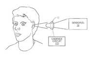
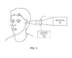
- FIG. 1shows an exemplary cadence measurement system disposed in an ear bud.
- FIG. 2shows a block diagram of an exemplary cadence measurement system.
- FIG. 3shows an exemplary process for determining the cadence from data provided by an inertial sensor.
- FIG. 4shows a block diagram of an exemplary cadence circuit.
- FIG. 5shows a more detailed process for determining a user cadence from data provided by an inertial sensor according to one exemplary embodiment.
- FIGS. 6A and 6Bshow simulated results associated with the disclosed solution.
- FIG. 1shows part of an exemplary cadence measurement system 10 , where one or more sensors 14 are disposed in an ear bud 12 , and a cadence circuit 100 is operatively connected to the sensor(s) 14 , e.g., via a wired or wireless connection.
- the cadence circuit 100may be secured to the user, e.g., via a clip.
- the ear bud 12may comprise a wireless or wired ear bud that communicatively couples to a remote device, e.g., a music player, a smart phone, a personal data assistant, etc. While not required, it will be appreciated that the cadence circuit 100 may be disposed in the remote device. While FIG. 1 shows the sensor(s) 14 as being part of an ear bud 12 , it will be appreciated that the sensor(s) 14 may be disposed in any device that secures to the body of a user, e.g., a device that secures to an ear, finger, toe, limb, ankle, wrist, nose, etc.
- the devicemay comprise a patch, e.g., a bandage, designed to attach the system 10 to any desired location on the user's body. While FIG. 1 shows the cadence circuit 100 as being separate from the ear bud 12 , it will be appreciated that the cadence circuit 100 may be disposed in the ear bud 12
- the cadence measurement system 10measures the user's cadence, and outputs the cadence to the user and/or to other processing functions or elements.
- the “cadence”refers to the number of repetitions or complete cycles per minute.
- Exemplary user cadencesinclude, but are not limited to, a step rate (e.g., the number of steps or foot repetitions per minute), a cycle rate (e.g., the number of pedaling cycles or cycle revolutions per minute), a repetition rate (e.g., with respect to lifting weights), etc. It will be appreciated that a step rate cadence may represent the user's cadence while walking, running, doing aerobics, climbing stairs, etc.
- the cadence measurement systemmay be used with any mobile animals having one or more limbs that facilitate and/or enable the animal's movement, or with machinery, e.g., a walking robot.
- exemplary animalsinclude, but are not limited to, biped animals (e.g., humans, birds, etc.) and quadruped animals (e.g., dogs, horses, etc.).
- FIG. 2shows a block diagram of an exemplary cadence measurement system 10 according to one exemplary embodiment.
- System 10comprises the cadence circuit 100 coupled to one or more sensors 14 and an input/output interface 16 , where the sensor(s) 14 include at least one inertial sensor 14 a , and an optional physiological sensor 14 b .
- the inertial sensor 14 amay incorporate a physiological sensor or physiological sensor capabilities.
- Inertial sensor 14 ais configured to sense energy, e.g., motion, external to the system 10 , and to output an inertial signal S i representative of the sensed energy.
- the inertial sensor 14 amay comprise a single axis sensor or a multiple axis sensor.
- Exemplary inertial sensors 14 ainclude but are not limited to accelerometers, Micro-Electro-Mechanical System (MEMS) devices, gyroscopes, optical sensors, an opto-mechanical sensor, a blocked channel sensor, a capacitive sensor, and a piezo sensor.
- MEMSMicro-Electro-Mechanical System
- gyroscopesoptical sensors
- an opto-mechanical sensore.g., a blocked channel sensor
- a capacitive sensore.g., a piezo sensor.
- the inertial sensor 14 acomprises a multiple axis sensor, frequency and power information from each axis may be combined or otherwise evaluated to determine the desired information, e.g., the peak frequency and the inertial power.
- the spectral magnitudemay be determined for each axis, where a maximum one of the spectral magnitudes, a sum of the squares, a maximum of the squares, a sum of the absolute values, a maximum of the absolute values, the root-sum-squares, the root-mean-squares, and/or the decimation of the spectral magnitudes is ultimately used to determine the inertial power and to identify the peak frequency.
- Cadence circuit 100processes the inertial signal S i as disclosed herein to determine a user cadence C.
- Input/output interface 16provides input from the user to the cadence circuit, and outputs the determined cadence C.
- input/output interface 16may include a display, a keyboard or other data entry device, and/or a transceiver for transmitting the cadence to a remote device. Alternatively or additionally, the input/output interface 16 may provide the cadence to the display, a database, a processor, and/or a processing function.
- FIG. 3shows an exemplary method 200 that may be implemented by the cadence measurement system 10 to determine a user cadence C. After the cadence circuit 100 receives the inertial signal S i from the inertial sensor 14 a (block 210 ), the cadence circuit 100 determines a peak frequency f p based on S i (block 220 ).
- the peak frequency f prepresents the frequency component of the inertial signal S i having the largest amplitude.
- the cadence circuit 100subsequently applies the peak frequency f p to one or more frequency threshold comparisons (block 230 ). Based on the frequency threshold comparisons, the cadence circuit 100 determines the user cadence C (block 240 ).
- FIG. 4shows a block diagram of an exemplary cadence circuit 100 configured to determine the user cadence from the inertial signal output by the inertial sensor 14 a .
- Cadence circuit 100comprises a peak frequency circuit 110 , a frequency comparison circuit 120 , and a cadence processor circuit 130 .
- Peak frequency circuit 110determines the peak frequency of the input inertial signal.
- the frequency comparison circuit 120applies the peak frequency to one or more frequency threshold comparisons.
- the cadence processor circuit 130determines the user cadence based on the peak frequency and the one or more frequency threshold comparisons.
- the peak frequency circuit 110identifies the frequency component of the inertial signal having the largest signal amplitude. In one exemplary embodiment, Peak frequency circuit 110 may achieve this goal by performing a frequency transform of the inertial signal to determine a spectral signal. The peak frequency circuit 110 then identifies the frequency component of the spectral signal having the largest amplitude as the peak frequency. It will be appreciated that other means, e.g., phase-locked loop, pulse picking, or time-domain implementations, may be used to determine the peak frequency.
- the frequency comparison circuit 120applies the peak frequency to one or more frequency threshold comparisons.
- the frequency peakoften corresponds directly to the user cadence.
- the user cadenceis some harmonic factor of the peak frequency.
- Empirical researchshows the peak frequency is often twice, half, or three-halves the user cadence.
- the typical walking harmonicsare 2 f p , 3/2f p , or 1 ⁇ 2f p and the typical running harmonics are 1 ⁇ 2f p .
- harmonics at 2f p and 3/2f poften occur when the user walks, but not when the user runs.
- the cadencemay actually be 1 ⁇ 2f p or 2 ⁇ 3f p , respectively.
- the cadence in this scenariomay actually be 2f p , 2 ⁇ 3f p , or 1 ⁇ 2f p .
- the cadence circuit 100must determine which harmonic factor, if any, is applicable to determining the current user cadence.
- the frequency threshold comparisons applied by the frequency comparison circuit 120 as disclosed hereinsolve this problem using one or more threshold comparisons, where the thresholds are determined based on a previous user cadence, an inertial power of the inertial signal, user activity parameters, user information, and/or empirical values. It will be appreciated that different harmonic factors and/or thresholds may apply depending on whether the user is sprinting, walking, running, ramping up from a low frequency value, cycling, etc. For example, harmonic factors due to arm swing, head bobbing, etc., impact the user cadence differently depending on how the user is moving, e.g., whether the user is running or walking.
- the cadence circuit 100may optionally comprise a power circuit 140 , a power comparison circuit 150 , a user input circuit 160 , a memory 170 , and/or a threshold processor circuit 180 that determine and/or provide the various harmonic factors and thresholds necessary to determine the user cadence.
- the power circuit 140is configured to determine the inertial power P i of the inertial signal. To that end, the power circuit 140 may compute the inertial power in the time domain, e.g., using the root mean square, or in the frequency domain, e.g., using the amplitude of a spectral peak. The power comparison circuit compares P i to an inertial power threshold T i to facilitate the determination of whether the user is running or walking.
- User input circuit 160receives input from the user. The user input may be used to determine one or more user activity parameters, e.g., whether the user is on foot or on wheels, whether sprinting is possible, etc.
- Threshold processor circuit 180is configured to determine one or more of the thresholds used by the frequency comparison circuit 120 , including any frequency thresholds used to determine a running cadence, a walking cadence, a cycling cadence, etc., and the power threshold used by the power comparison circuit 150 .
- Memory 170stores any predetermined thresholds, one or more previously determined cadences C p , the various harmonic factors used by the cadence processor circuit 130 , and any other information or software necessary for successful operation of the cadence circuit 100 .
- FIG. 5shows an exemplary detailed process 300 executed by the cadence circuit 100 to determine the user cadence C.
- cadence circuit 100determines the user cadence based on the peak frequency and one or more frequency threshold comparisons.
- the cadence circuit 100determines a user activity parameter, and determines the user cadence based on the frequency threshold comparison(s) and the user activity parameter.
- the user activity parametermay identify whether the user is on foot or on wheels (block 302 ).
- the frequency comparison circuit 120compares the peak frequency f p to a cycling threshold T c , which may be fixed or variably determined based on an inertial power of the inertial signal (block 310 ).
- the cadence processor circuit 130sets the user cadence equal to C 1 (block 318 ). If C 2 is closer to C p than C 1 or C 3 are, the cadence processor circuit 130 sets the user cadence equal to C 2 (block 320 ). If C 3 is closer to C p than C 2 or C 1 are, the cadence processor circuit 130 sets the user cadence equal to C 3 (block 322 ). While the example of FIG. 5 shows determining and using three specific test cadences, it will be appreciated that any two or more test cadences may be used.
- the cadence processor circuit 130sets the user cadence equal to the peak frequency divided by a harmonic factor, e.g., 1 ⁇ 2, 1, 3/2, 2, etc. More particularly, the cadence processor circuit 130 determines the user cadence based on frequency and power comparisons respectively performed by the frequency comparison circuit 120 and the power comparison circuit 150 (block 330 ).
- a harmonic factore.g. 1 ⁇ 2, 1, 3/2, 2, etc.
- the cadence processor circuit 130sets the user cadence equal to C 1 (block 364 ). If C 2 is closer to C p than C 1 or C 3 are, the cadence processor circuit 130 sets the user cadence equal to C 2 (block 366 ). If C 3 is closer to C p than C 2 or C 1 are, the cadence processor circuit 130 sets the user cadence equal to C 3 (block 368 ). While the example of FIG. 5 shows determining and using three specific test cadences, it will be appreciated that any two or more test cadences may be used.
- the cadence processor circuit 130determines the user cadence based on frequency threshold comparison(s) and a sprinting user activity parameter, which indicates whether sprinting conditions are possible (blocks 332 - 356 ). More particularly, when P i ⁇ T i and/or f p ⁇ T foot , the cadence processor circuit 130 determines whether sprinting conditions are possible based on user input (block 332 ). For example, the user may select an activity mode, e.g., walking, slow or low impact aerobics, high impact aerobics, running, etc. from a menu of options. Based on the selected activity mode, the cadence processor circuit 130 determines whether sprinting conditions are possible.
- an activity modee.g., walking, slow or low impact aerobics, high impact aerobics, running, etc.
- the cadence processor circuit 130determines that sprinting is not possible. Alternatively, when the user selects running, the cadence processor circuit 130 determines that sprinting is possible. If sprinting conditions are possible, the cadence processor circuit 130 determines the user cadence based on a comparison between f p and a low frequency threshold T low under sprinting conditions (blocks 334 - 338 ). When f p ⁇ T low , the cadence processor circuit 130 sets the user cadence equal to the peak frequency divided by the 1 ⁇ 2 harmonic factor, e.g., equal to twice the peak frequency (block 336 ). Otherwise, the cadence processor circuit 130 sets the user cadence equal to the peak frequency (block 338 ).
- the cadence processor circuit 130determines the user cadence based on multiple frequency threshold comparisons under non-sprinting conditions (blocks 340 - 356 ). More particularly, the cadence processor circuit applies the peak frequency to multiple thresholds based on whether the peak frequency is ramping up from a low frequency value (block 340 ), and determines the user cadence based on that ramping information and the frequency threshold conditions (blocks 342 - 356 ). While not required, in some exemplary embodiments, the low frequency value is zero. During non-sprinting conditions when the peak frequency is ramping up from a low frequency value, the cadence processor circuit 130 sets the user cadence equal to the peak frequency (block 342 ).
- the cadence processor circuit 130determines the user cadence based on multiple peak frequency threshold comparisons determined by the frequency comparison circuit 120 under non-sprinting conditions relative to a low frequency threshold T low , an intermediate frequency threshold T med , and a high frequency threshold T high , where T low ⁇ T med ⁇ T high (blocks 344 - 356 ). More particularly, under these conditions when f p ⁇ T low (block 344 ), the cadence processor circuit 130 sets the user cadence equal to the peak frequency divided by the 1 ⁇ 2 harmonic factor, e.g., equal to twice the peak frequency (block 346 ).
- the cadence processor circuit 130sets the user cadence equal to the peak frequency divided by the 2 harmonic factor, e.g., equal to half the peak frequency (block 350 ).
- the cadence processor circuit 130sets the user cadence equal to the peak frequency divided by the 3/2 harmonic factor, e.g., equal to two-thirds the peak frequency (block 354 ). Otherwise, the cadence processor circuit 130 sets the user cadence equal to the peak frequency (block 356 ).
- the cadence circuit 100determines the user cadence based on one or more frequency threshold comparisons.
- Each frequency threshold, as well as the inertial power thresholdmay be determined empirically or based on one or more parameters, e.g., a previous user cadence, an inertial power, user information, and/or a user activity parameter.
- the cycling threshold T c and/or the foot threshold T footmay be determined empirically based on observation, and/or based on user input information, user activity parameter, and/or the inertial power.
- the foot thresholdmay be determined according to:
- An exemplary cycling threshold T cis 100 revolutions per minute, while an exemplary foot threshold T foot is 145 steps per minute.
- the inertial power threshold and/or the low thresholdmay be determined empirically and/or based on user information, e.g., the user's weight, shoe sole compliance information, etc., the inertial power, a previous user cadence, and/or user activity parameters.
- T low60 (a constant). It has been shown, for example, that the low frequency threshold is more accurate when determined as a function of the inertial power. For example, when P i ⁇ T i , the low threshold may be determined based on the inertial power when according to:
- T low60 + 20 ⁇ P i T i . ( 2 )
- T lowmay be set equal to 80.
- the intermediate and high thresholdsmay be determined based on a previous user cadence and/or the inertial power. For example, the intermediate and high thresholds may be determined as a function of the previous user cadence and a sprint factor.
- the sprint factor for the intermediate thresholdmay be determined empirically, e.g., based on 1.75 times the previous user cadence.
- the sprint factor for the intermediate thresholdmay also be determined empirically, e.g., based on 1.4 times the previous user cadence.
- each thresholdmay be fixed or variable. It will also be appreciated that the frequency thresholds (e.g., T c , T foot , T low , T med , T high ) and the inertial power threshold (T i ) discussed herein are exemplary and non-limiting; other thresholds may be used depending on the system configuration, the information available to the cadence circuit 100 , etc.
- the frequency thresholdse.g., T c , T foot , T low , T med , T high
- T iinertial power threshold
- the user cadence method and apparatus disclosed hereinaccurately determines a user cadence for a wide range of circumstances and environments. Further, because the user may wear the hardware necessary to implement this invention, the invention disclosed herein is applicable for any user activity, including cycling, walking, running, athletic training, sports, aerobics, weight lifting or any other repetitive exercises, jumping, etc.
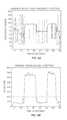
- FIGS. 6A and 6Bshow simulated results for one exemplary implementation of the cadence measurement system disclosed herein.
- the plots shown in FIGS. 6A and 6Bare generated from the same data set produced by an individual running and walking on a treadmill.
- FIG. 6Ashows the user cadence with respect to time as computed according to FIG. 5 using the spectral peak frequency provided by the inertial sensor.
- FIG. 6Bshows the inertial power output by the inertial sensor with respect to time.
- FIG. 6Balso shows an exemplary inertial power threshold of 2000, which is used to determine whether the user is running or walking/resting.
- the circuits for the y-axis circuits Figure Bare “g's” scaled by a systematic multiplier, where 1 g is the force of gravity on Earth at sea level.
- 1 gis the force of gravity on Earth at sea level.
- the useris running from 125-215, seconds and from 300-375 seconds.
- user cadence method and apparatus disclosed hereinavoids mistaking the peak frequencies above 145 steps per minute as 2 ⁇ or 3/2 ⁇ harmonics.
- the 40-70 seconds regionshows 3/2 ⁇ and 1 ⁇ 2 ⁇ harmonics
- the 80-120 seconds regionshows 2 ⁇ and 1 ⁇ 2 ⁇ harmonics
- the 125-215 seconds regionshows 1 ⁇ 2 ⁇ harmonics. All of these harmonics, when divided by the corresponding harmonic factor as disclosed herein, produce the correct user cadence.
- the cadence measurement system 10may also comprise additional sensors.
- the cadence measurement system 10may include additional physiological sensors 14 b , e.g., blood flow (photoplethysmography (PPG)), body temperature, and/or heart rate sensors.
- PPGphotoplethysmography
- a noise circuit 18may be included to remove or otherwise attenuate cadence-related motion artifact noise from a physiological signal based on the determined user cadence output by the cadence circuit 100 .
- the determined cadence frequencymay be selectively removed from the frequency spectrum of the outputs of one or more of the sensors 14 so that higher-quality sensor outputs are achieved with substantially attenuated motion artifacts.
- the senor 14may comprise an opto-mechanical sensor, comprising at least one optical emitter and one optical detector, such that inertial changes and cadence can be detected by the spectral characteristics of the opto-mechanical sensor output.
- the thresholds described hereinmay be adapted when applied to the opto-mechanical sensor to account for differences in the sensing mechanism between an opto-mechanical sensor and an accelerometer, thereby generating an accurate measurement of cadence.
- the opto-mechanical sensormay also be configured to shine light at the skin and detect light scattered from or through the skin to produce an output signal comprising both photoplethysmography components and inertial components.
- the cadence measurement generated by the opto-mechanical sensorcan be removed from the opto-mechanical sensor output to provide a second output having a cleaner photoplethysmography signal with substantially attenuated motion artifacts from cadence.
Landscapes
- Health & Medical Sciences (AREA)
- Life Sciences & Earth Sciences (AREA)
- Engineering & Computer Science (AREA)
- Physics & Mathematics (AREA)
- Molecular Biology (AREA)
- Surgery (AREA)
- Veterinary Medicine (AREA)
- Public Health (AREA)
- General Health & Medical Sciences (AREA)
- Biophysics (AREA)
- Pathology (AREA)
- Biomedical Technology (AREA)
- Heart & Thoracic Surgery (AREA)
- Medical Informatics (AREA)
- Animal Behavior & Ethology (AREA)
- Physiology (AREA)
- Signal Processing (AREA)
- Psychiatry (AREA)
- Artificial Intelligence (AREA)
- Computer Vision & Pattern Recognition (AREA)
- Otolaryngology (AREA)
- Dentistry (AREA)
- Oral & Maxillofacial Surgery (AREA)
- General Physics & Mathematics (AREA)
- Radar, Positioning & Navigation (AREA)
- Remote Sensing (AREA)
- Measurement Of The Respiration, Hearing Ability, Form, And Blood Characteristics Of Living Organisms (AREA)
- Train Traffic Observation, Control, And Security (AREA)
Abstract
Description
When Pi>Ti, alternatively, Tlowmay be set equal to 80. In another exemplary embodiment, the low threshold may be determined based on the previous user cadence according to:
Tlow=0.6Cp. (3)
Claims (18)
Priority Applications (1)
| Application Number | Priority Date | Filing Date | Title |
|---|---|---|---|
| US14/655,992US9993204B2 (en) | 2013-01-09 | 2014-01-06 | Cadence detection based on inertial harmonics |
Applications Claiming Priority (3)
| Application Number | Priority Date | Filing Date | Title |
|---|---|---|---|
| US201361750490P | 2013-01-09 | 2013-01-09 | |
| PCT/US2014/010326WO2014109982A2 (en) | 2013-01-09 | 2014-01-06 | Cadence detection based on inertial harmonics |
| US14/655,992US9993204B2 (en) | 2013-01-09 | 2014-01-06 | Cadence detection based on inertial harmonics |
Related Parent Applications (1)
| Application Number | Title | Priority Date | Filing Date |
|---|---|---|---|
| PCT/US2014/010326A-371-Of-InternationalWO2014109982A2 (en) | 2013-01-09 | 2014-01-06 | Cadence detection based on inertial harmonics |
Related Child Applications (1)
| Application Number | Title | Priority Date | Filing Date |
|---|---|---|---|
| US15/958,113ContinuationUS11363987B2 (en) | 2013-01-09 | 2018-04-20 | Cadence detection based on inertial harmonics |
Publications (2)
| Publication Number | Publication Date |
|---|---|
| US20150366509A1 US20150366509A1 (en) | 2015-12-24 |
| US9993204B2true US9993204B2 (en) | 2018-06-12 |
Family
ID=51167494
Family Applications (2)
| Application Number | Title | Priority Date | Filing Date |
|---|---|---|---|
| US14/655,992Active2034-04-08US9993204B2 (en) | 2013-01-09 | 2014-01-06 | Cadence detection based on inertial harmonics |
| US15/958,113Active2035-03-29US11363987B2 (en) | 2013-01-09 | 2018-04-20 | Cadence detection based on inertial harmonics |
Family Applications After (1)
| Application Number | Title | Priority Date | Filing Date |
|---|---|---|---|
| US15/958,113Active2035-03-29US11363987B2 (en) | 2013-01-09 | 2018-04-20 | Cadence detection based on inertial harmonics |
Country Status (4)
| Country | Link |
|---|---|
| US (2) | US9993204B2 (en) |
| EP (1) | EP2943753B1 (en) |
| CN (1) | CN104969035B (en) |
| WO (1) | WO2014109982A2 (en) |
Cited By (4)
| Publication number | Priority date | Publication date | Assignee | Title |
|---|---|---|---|---|
| US20180235550A1 (en)* | 2013-01-09 | 2018-08-23 | Valencell, Inc. | Cadence Detection Based on Inertial Harmonics |
| US10335045B2 (en) | 2016-06-24 | 2019-07-02 | Universita Degli Studi Di Trento | Self-adaptive matrix completion for heart rate estimation from face videos under realistic conditions |
| US10860114B1 (en) | 2019-06-20 | 2020-12-08 | Bose Corporation | Gesture control and pulse measurement through embedded films |
| US11298036B2 (en) | 2014-02-28 | 2022-04-12 | Valencell, Inc. | Wearable device including PPG and inertial sensors for assessing physical activity and biometric parameters |
Families Citing this family (18)
| Publication number | Priority date | Publication date | Assignee | Title |
|---|---|---|---|---|
| EP3127476A1 (en) | 2009-02-25 | 2017-02-08 | Valencell, Inc. | Light-guiding devices and monitoring devices incorporating same |
| US8788002B2 (en) | 2009-02-25 | 2014-07-22 | Valencell, Inc. | Light-guiding devices and monitoring devices incorporating same |
| US8888701B2 (en) | 2011-01-27 | 2014-11-18 | Valencell, Inc. | Apparatus and methods for monitoring physiological data during environmental interference |
| WO2013016007A2 (en) | 2011-07-25 | 2013-01-31 | Valencell, Inc. | Apparatus and methods for estimating time-state physiological parameters |
| WO2013019494A2 (en) | 2011-08-02 | 2013-02-07 | Valencell, Inc. | Systems and methods for variable filter adjustment by heart rate metric feedback |
| JP6116017B2 (en) | 2012-01-16 | 2017-04-19 | ヴァレンセル, インコーポレイテッドValencell, Inc. | Reduction of physiological measurement error by inertia rhythm |
| WO2013109389A1 (en) | 2012-01-16 | 2013-07-25 | Valencell, Inc. | Physiological metric estimation rise and fall limiting |
| CN110013239A (en) | 2013-01-28 | 2019-07-16 | 瓦伦赛尔公司 | Physiological monitoring device with the sensing element disengaged with body kinematics |
| EP3199100A1 (en) | 2014-08-06 | 2017-08-02 | Valencell, Inc. | Earbud with a physiological information sensor module |
| EP3090684A1 (en)* | 2015-05-08 | 2016-11-09 | The Swatch Group Research and Development Ltd. | Pedometer and method for analyzing motion data |
| EP3090685A1 (en)* | 2015-05-08 | 2016-11-09 | The Swatch Group Research and Development Ltd. | Pedometer and method for analyzing motion data |
| US9536560B2 (en) | 2015-05-19 | 2017-01-03 | Spotify Ab | Cadence determination and media content selection |
| US9568994B2 (en)* | 2015-05-19 | 2017-02-14 | Spotify Ab | Cadence and media content phase alignment |
| US10610158B2 (en) | 2015-10-23 | 2020-04-07 | Valencell, Inc. | Physiological monitoring devices and methods that identify subject activity type |
| US10945618B2 (en) | 2015-10-23 | 2021-03-16 | Valencell, Inc. | Physiological monitoring devices and methods for noise reduction in physiological signals based on subject activity type |
| WO2017186800A1 (en)* | 2016-04-29 | 2017-11-02 | Sanko Tekstil Isletmeleri San. Ve Tic. A.S. | Wearable step counter system |
| WO2018009736A1 (en) | 2016-07-08 | 2018-01-11 | Valencell, Inc. | Motion-dependent averaging for physiological metric estimating systems and methods |
| US11694771B2 (en)* | 2017-03-22 | 2023-07-04 | Bragi GmbH | System and method for populating electronic health records with wireless earpieces |
Citations (108)
| Publication number | Priority date | Publication date | Assignee | Title |
|---|---|---|---|---|
| US3636617A (en) | 1970-03-23 | 1972-01-25 | Monsanto Co | Method for fabricating monolithic light-emitting semiconductor diodes and arrays thereof |
| US3704706A (en) | 1969-10-23 | 1972-12-05 | Univ Drexel | Heart rate and respiratory monitor |
| US4672976A (en) | 1986-06-10 | 1987-06-16 | Cherne Industries, Inc. | Heart sound sensor |
| JPH0258039A (en) | 1988-08-24 | 1990-02-27 | Nikon Corp | camera system |
| US4952928A (en) | 1988-08-29 | 1990-08-28 | B. I. Incorporated | Adaptable electronic monitoring and identification system |
| US4955379A (en) | 1987-08-14 | 1990-09-11 | National Research Development Corporation | Motion artefact rejection system for pulse oximeters |
| US5139025A (en) | 1983-10-14 | 1992-08-18 | Somanetics Corporation | Method and apparatus for in vivo optical spectroscopic examination |
| US5243992A (en) | 1990-03-30 | 1993-09-14 | Colin Electronics Co., Ltd. | Pulse rate sensor system |
| US5297548A (en) | 1992-02-07 | 1994-03-29 | Ohmeda Inc. | Arterial blood monitoring probe |
| US5299570A (en) | 1991-08-12 | 1994-04-05 | Avl Medical Instruments Ag | System for measuring the saturation of at least one gas, particularly the oxygen saturation of blood |
| US5448082A (en) | 1994-09-27 | 1995-09-05 | Opto Diode Corporation | Light emitting diode for use as an efficient emitter or detector of light at a common wavelength and method for forming the same |
| US5482036A (en) | 1991-03-07 | 1996-01-09 | Masimo Corporation | Signal processing apparatus and method |
| US5494043A (en) | 1993-05-04 | 1996-02-27 | Vital Insite, Inc. | Arterial sensor |
| US5503016A (en) | 1994-02-01 | 1996-04-02 | Ic Sensors, Inc. | Vertically mounted accelerometer chip |
| EP0729726A2 (en) | 1995-02-20 | 1996-09-04 | Seiko Epson Corporation | Pulse rate meter |
| US5575284A (en) | 1994-04-01 | 1996-11-19 | University Of South Florida | Portable pulse oximeter |
| US5673692A (en) | 1995-02-03 | 1997-10-07 | Biosignals Ltd. Co. | Single site, multi-variable patient monitor |
| US5807267A (en) | 1994-06-01 | 1998-09-15 | Advanced Body Metrics Corporation | Heart pulse monitor |
| JPH10258039A (en) | 1997-03-17 | 1998-09-29 | Seiko Epson Corp | Pulse meter |
| US5846190A (en) | 1995-10-10 | 1998-12-08 | Hewlett-Packard Company | Method of and apparatus for recognizing falsified pulse oximetry measurements |
| US5853005A (en) | 1996-05-02 | 1998-12-29 | The United States Of America As Represented By The Secretary Of The Army | Acoustic monitoring system |
| US5906582A (en) | 1994-09-14 | 1999-05-25 | Seiko Epson Corporation | Organism information measuring method and arm wear type pulse-wave measuring method |
| US5908396A (en)* | 1995-10-18 | 1999-06-01 | Seiko Epson Corporation | Pitch measurement device, electronic instrument, and pitch measurement method |
| US5941837A (en) | 1995-12-18 | 1999-08-24 | Seiko Epson Corporation | Health management device and exercise support device |
| US5954644A (en) | 1997-03-24 | 1999-09-21 | Ohmeda Inc. | Method for ambient light subtraction in a photoplethysmographic measurement instrument |
| US5964701A (en) | 1996-10-24 | 1999-10-12 | Massachusetts Institute Of Technology | Patient monitoring finger ring sensor |
| US6022748A (en) | 1997-08-29 | 2000-02-08 | Sandia Corporation - New Mexico Regents Of The University Of California | Sol-gel matrices for direct colorimetric detection of analytes |
| US6042549A (en)* | 1996-03-22 | 2000-03-28 | Seiko Epson Corporation | Exercise intensity measuring device and exercise quantity measuring device |
| WO2000021435A1 (en) | 1998-10-13 | 2000-04-20 | Somanetics Corporation | Multi-channel non-invasive tissue oximeter |
| US6067462A (en) | 1997-04-14 | 2000-05-23 | Masimo Corporation | Signal processing apparatus and method |
| US6198394B1 (en) | 1996-12-05 | 2001-03-06 | Stephen C. Jacobsen | System for remote monitoring of personnel |
| US6241684B1 (en) | 1996-04-08 | 2001-06-05 | Seiko Epson Corporation | Exercise workout support device |
| US6267721B1 (en) | 1999-06-18 | 2001-07-31 | William F. Welles | Method and apparatus for stress relief system |
| US20020013538A1 (en) | 1997-09-30 | 2002-01-31 | David Teller | Method and apparatus for health signs monitoring |
| US6393311B1 (en) | 1998-10-15 | 2002-05-21 | Ntc Technology Inc. | Method, apparatus and system for removing motion artifacts from measurements of bodily parameters |
| US6443890B1 (en) | 2000-03-01 | 2002-09-03 | I-Medik, Inc. | Wireless internet bio-telemetry monitoring system |
| US6527711B1 (en) | 1999-10-18 | 2003-03-04 | Bodymedia, Inc. | Wearable human physiological data sensors and reporting system therefor |
| US20030065269A1 (en) | 2001-09-28 | 2003-04-03 | Csem Centre Suisse D'electronique Et De Microtechnique Sa | Method and device for pulse rate detection |
| US20030109791A1 (en) | 2001-12-10 | 2003-06-12 | Shinji Kondo | Biological data observation apparatus |
| US6608562B1 (en) | 1999-08-31 | 2003-08-19 | Denso Corporation | Vital signal detecting apparatus |
| US20030176815A1 (en) | 2002-03-14 | 2003-09-18 | Norimitsu Baba | Physical activity measurement apparatus |
| US6656151B1 (en) | 2000-01-11 | 2003-12-02 | Integrated Vascular Interventional Technologies, L.C. (Ivit, Lc) | Vascular access devices and systems |
| US20030233051A1 (en) | 2002-06-18 | 2003-12-18 | Christophe Verjus | Portable equipment for measuring and/or monitoring the heart rate |
| US20030236647A1 (en) | 2002-03-16 | 2003-12-25 | Yoon Gil-Won | Diagnostic method and apparatus using light |
| US20040004547A1 (en) | 2002-05-17 | 2004-01-08 | Fireeye Development Incorporated | System and method for identifying, monitoring and evaluating equipment, environmental and physiological conditions |
| US20040039254A1 (en) | 2002-08-22 | 2004-02-26 | Stivoric John M. | Apparatus for detecting human physiological and contextual information |
| US20040054291A1 (en) | 2002-09-14 | 2004-03-18 | Christian Schulz | Pulse oximetry ear sensor |
| US20040059236A1 (en) | 2002-09-20 | 2004-03-25 | Margulies Lyle Aaron | Method and apparatus for monitoring the autonomic nervous system |
| US6725072B2 (en) | 1990-10-06 | 2004-04-20 | Hema Metrics, Inc. | Sensor for transcutaneous measurement of vascular access blood flow |
| US6748254B2 (en) | 2001-10-12 | 2004-06-08 | Nellcor Puritan Bennett Incorporated | Stacked adhesive optical sensor |
| US20040178913A1 (en) | 2002-03-18 | 2004-09-16 | Oswaldo Penuela | Physical condition or environmental threat detection appliance system |
| US20040186695A1 (en)* | 2003-03-07 | 2004-09-23 | Seiko Epson Corporation | Body motion detection device, pitch meter, wristwatch-type information processing device, method for controlling thereof, control program, and storage medium |
| US20040186387A1 (en) | 2003-03-19 | 2004-09-23 | Seiko Epson Corporation | Pulse meter, method for controlling pulse meter, wristwatch-type information device, control program, storage medium, blood vessel simulation sensor, and living organism information measurement device |
| JP2004283228A (en) | 2003-03-19 | 2004-10-14 | Seiko Epson Corp | Information collection device and pulse meter |
| US20040242976A1 (en) | 2002-04-22 | 2004-12-02 | Abreu Marcio Marc | Apparatus and method for measuring biologic parameters |
| US20040254501A1 (en) | 2000-08-11 | 2004-12-16 | Mault James R. | Achieving a relaxed state |
| JP2004358271A (en) | 2003-03-19 | 2004-12-24 | Seiko Epson Corp | Blood vessel simulation sensor, pulse meter, and biological information measurement device |
| US20050007582A1 (en) | 2003-07-07 | 2005-01-13 | Lumidigm, Inc. | Methods and apparatus for collection of optical reference measurements for monolithic sensors |
| WO2005010568A2 (en) | 2003-07-21 | 2005-02-03 | The Titan Corporation | Optical vital signs monitor |
| US20050043652A1 (en)* | 2003-08-18 | 2005-02-24 | Lovett Eric G. | Sleep state classification |
| US20050059870A1 (en) | 2003-08-25 | 2005-03-17 | Aceti John Gregory | Processing methods and apparatus for monitoring physiological parameters using physiological characteristics present within an auditory canal |
| US20050192516A1 (en) | 2000-12-27 | 2005-09-01 | Sony Corporation | Gait detection system, gait detection apparatus, device, and gait detection method |
| US20050209516A1 (en) | 2004-03-22 | 2005-09-22 | Jacob Fraden | Vital signs probe |
| US20050228463A1 (en) | 2004-04-01 | 2005-10-13 | Bia Mac | Method and apparatus for treating the body |
| US20050245839A1 (en) | 2002-08-22 | 2005-11-03 | John Stivoric | Non-invasive temperature monitoring device |
| US6997879B1 (en) | 2002-07-09 | 2006-02-14 | Pacesetter, Inc. | Methods and devices for reduction of motion-induced noise in optical vascular plethysmography |
| US20060064037A1 (en) | 2004-09-22 | 2006-03-23 | Shalon Ventures Research, Llc | Systems and methods for monitoring and modifying behavior |
| US20060084879A1 (en) | 2004-10-15 | 2006-04-20 | Pulsetracer Technologies Inc. | Motion cancellation of optical input signals for physiological pulse measurement |
| US20060258927A1 (en)* | 1998-10-15 | 2006-11-16 | Edgar Reuben W Jr | Method, apparatus, and system for removing motion artifacts from measurements of bodily parameters |
| US7144375B2 (en) | 2002-09-06 | 2006-12-05 | Seiko Epson Corporation | Pulsimeter, control method for pulsimeter, wristwatch information device, control program, and recording medium |
| US20070016086A1 (en) | 2005-06-29 | 2007-01-18 | Fukuda Denshi Co., Ltd. | Blood pressure monitoring apparatus |
| WO2007013054A1 (en) | 2005-07-28 | 2007-02-01 | Boris Schwartz | Ear-mounted biosensor |
| US20070116314A1 (en) | 2005-10-11 | 2007-05-24 | Morning Pride Manufacturing, L.L.C. | Facemask-earpiece combination |
| US20070135717A1 (en) | 2003-10-09 | 2007-06-14 | Nippon Telegraph And Telephone Corp | Organism information detection device and sphygmomanometer |
| WO2007122375A2 (en) | 2006-04-11 | 2007-11-01 | The University Of Nottingham | Photoplethysmography |
| US7336982B2 (en) | 2003-07-07 | 2008-02-26 | Sun Kook Yoo | Photoplethysmography (PPG) device and the method thereof |
| US20080076972A1 (en) | 2006-09-21 | 2008-03-27 | Apple Inc. | Integrated sensors for tracking performance metrics |
| US20080081972A1 (en) | 2006-09-29 | 2008-04-03 | Nellcor Puritan Bennett Incorporated | Symmetric LED array for pulse oximetry |
| US7378954B2 (en) | 2005-10-21 | 2008-05-27 | Barry Myron Wendt | Safety indicator and method |
| US20080132798A1 (en) | 2006-11-30 | 2008-06-05 | Motorola, Inc | Wireless headsets and wireless communication networks for heart rate monitoring |
| US20080146890A1 (en) | 2006-12-19 | 2008-06-19 | Valencell, Inc. | Telemetric apparatus for health and environmental monitoring |
| US20080154098A1 (en) | 2006-12-20 | 2008-06-26 | Margaret Morris | Apparatus for monitoring physiological, activity, and environmental data |
| US20080177162A1 (en) | 2007-01-24 | 2008-07-24 | Samsung Electronics Co., Ltd. | Biosignal measurement apparatus and the method thereof |
| US7438688B2 (en) | 2005-08-26 | 2008-10-21 | Nihon Kohden Corporation | Apparatus and method for measuring pulse rate |
| US20080269625A1 (en) | 2004-02-05 | 2008-10-30 | Earlysense Ltd. | Prediction and monitoring of clinical episodes |
| US20090010461A1 (en) | 2007-07-02 | 2009-01-08 | Gunnar Klinghult | Headset assembly for a portable mobile communications device |
| US20090023556A1 (en) | 2007-07-18 | 2009-01-22 | Daly Juliette C | Sensing applications for exercise machines |
| US20090097689A1 (en) | 2007-10-16 | 2009-04-16 | Christopher Prest | Sports Monitoring System for Headphones, Earbuds and/or Headsets |
| US20090105556A1 (en) | 2007-09-28 | 2009-04-23 | Tiax Llc | Measurement of physiological signals |
| US20090112111A1 (en) | 2005-09-15 | 2009-04-30 | Citizen Holdings Co., Ltd. | Heart rate meter and method for removing noise of heart beat waveform |
| US20090131761A1 (en) | 2005-06-30 | 2009-05-21 | Koninklijke Philips Electronics N. V. | Device providing spot-check of vital signs using an in-the-ear probe |
| US7539533B2 (en) | 2006-05-16 | 2009-05-26 | Bao Tran | Mesh network monitoring appliance |
| US20090281435A1 (en) | 2008-05-07 | 2009-11-12 | Motorola, Inc. | Method and apparatus for robust heart rate sensing |
| US20090306736A1 (en) | 2005-02-07 | 2009-12-10 | Dobak Iii John D | Accelerometer-based monitoring of the frequency dynamics of the isovolumic contraction phase and pathologic cardiac vibrations |
| US20100189209A1 (en) | 2007-07-02 | 2010-07-29 | Atcor Medical Pty. Ltd. | Step Rate Optimization Device |
| EP2229880A1 (en) | 2009-03-18 | 2010-09-22 | CSEM Centre Suisse d'Electronique et de Microtechnique SA | Headband integrated monitoring unit using an accelerometer |
| WO2011105914A1 (en) | 2010-02-24 | 2011-09-01 | Ackland, Kerri Anne | Classification system and method |
| EP2182839B1 (en) | 2007-07-20 | 2011-10-26 | Bmeye B.V. | A cuff for determining a physiological parameter |
| US8055469B2 (en) | 2006-03-03 | 2011-11-08 | Garmin Switzerland Gmbh | Method and apparatus for determining the attachment position of a motion sensing apparatus |
| US20120197093A1 (en) | 2011-01-27 | 2012-08-02 | Leboeuf Steven Francis | Apparatus and methods for monitoring physiological data during environmental interference |
| US20120303319A1 (en) | 2010-02-02 | 2012-11-29 | Nokia Corporation | Pedometer device and step detection method |
| US20130006583A1 (en) | 2011-07-01 | 2013-01-03 | Nike, Inc. | Sensor-Based Athletic Activity Measurements |
| WO2013038296A1 (en) | 2011-09-16 | 2013-03-21 | Koninklijke Philips Electronics N.V. | Device and method for estimating the heart rate during motion |
| WO2013109390A1 (en) | 2012-01-16 | 2013-07-25 | Valencell, Inc. | Reduction of physiological metric error due to inertial cadence |
| WO2013109389A1 (en) | 2012-01-16 | 2013-07-25 | Valencell, Inc. | Physiological metric estimation rise and fall limiting |
| US8923941B2 (en) | 2009-02-25 | 2014-12-30 | Valencell, Inc. | Methods and apparatus for generating data output containing physiological and motion-related information |
| US9005129B2 (en) | 2012-06-22 | 2015-04-14 | Fitbit, Inc. | Wearable heart rate monitor |
| US9044180B2 (en) | 2007-10-25 | 2015-06-02 | Valencell, Inc. | Noninvasive physiological analysis using excitation-sensor modules and related devices and methods |
Family Cites Families (19)
| Publication number | Priority date | Publication date | Assignee | Title |
|---|---|---|---|---|
| KR100462182B1 (en) | 2002-04-15 | 2004-12-16 | 삼성전자주식회사 | Apparatus and method for detecting heart beat using ppg |
| KR20040032451A (en) | 2002-10-09 | 2004-04-17 | 삼성전자주식회사 | Mobile device having health care function and method of health care using the same |
| US20060178588A1 (en) | 2005-01-03 | 2006-08-10 | Lee Brody | System and method for isolating effects of basal autonomic nervous system activity on heart rate variability |
| JP4967368B2 (en) | 2006-02-22 | 2012-07-04 | ソニー株式会社 | Body motion detection device, body motion detection method, and body motion detection program |
| CN101980659B (en)* | 2008-03-31 | 2012-08-29 | 夏普株式会社 | Body motion measuring device, mobile telephone, method for controlling the body motion measuring device |
| US8996332B2 (en) | 2008-06-24 | 2015-03-31 | Dp Technologies, Inc. | Program setting adjustments based on activity identification |
| TWI449514B (en) | 2009-04-28 | 2014-08-21 | 私立中原大學 | Measurement of arrhythmia |
| ES2703605T3 (en) | 2009-09-03 | 2019-03-11 | Csem Ct Suisse Delectronique Microtechnique Sa Rech Developpement | Monitoring device and method to estimate the concentration of blood constituents for tissues with low perfusion |
| JP4991822B2 (en)* | 2009-10-19 | 2012-08-01 | パナソニック株式会社 | Physical activity measuring device |
| JP4877395B2 (en) | 2010-01-19 | 2012-02-15 | セイコーエプソン株式会社 | Stride estimation method and stride estimation apparatus |
| JP2012008637A (en)* | 2010-06-22 | 2012-01-12 | Yamaha Corp | Pedometer and program |
| KR20120020051A (en)* | 2010-08-27 | 2012-03-07 | 야마하 가부시키가이샤 | Pedometer, sampling device, and waveform analyzer |
| US9167991B2 (en) | 2010-09-30 | 2015-10-27 | Fitbit, Inc. | Portable monitoring devices and methods of operating same |
| US9717412B2 (en) | 2010-11-05 | 2017-08-01 | Gary And Mary West Health Institute | Wireless fetal monitoring system |
| AU2010362586B2 (en)* | 2010-12-30 | 2016-06-30 | Ar Innovation Ag | Method for configuring a motion sensor as well as a configurable motion sensor and a system for configuring such a motion sensor |
| US20130178958A1 (en) | 2012-01-09 | 2013-07-11 | Garmin Switzerland Gmbh | Method and system for determining user performance characteristics |
| WO2014109982A2 (en)* | 2013-01-09 | 2014-07-17 | Valencell Inc. | Cadence detection based on inertial harmonics |
| EP3146896B1 (en) | 2014-02-28 | 2020-04-01 | Valencell, Inc. | Method and apparatus for generating assessments using physical activity and biometric parameters |
| US10610158B2 (en) | 2015-10-23 | 2020-04-07 | Valencell, Inc. | Physiological monitoring devices and methods that identify subject activity type |
- 2014
- 2014-01-06WOPCT/US2014/010326patent/WO2014109982A2/enactiveApplication Filing
- 2014-01-06CNCN201480004411.6Apatent/CN104969035B/enactiveActive
- 2014-01-06USUS14/655,992patent/US9993204B2/enactiveActive
- 2014-01-06EPEP14737554.7Apatent/EP2943753B1/enactiveActive
- 2018
- 2018-04-20USUS15/958,113patent/US11363987B2/enactiveActive
Patent Citations (113)
| Publication number | Priority date | Publication date | Assignee | Title |
|---|---|---|---|---|
| US3704706A (en) | 1969-10-23 | 1972-12-05 | Univ Drexel | Heart rate and respiratory monitor |
| US3636617A (en) | 1970-03-23 | 1972-01-25 | Monsanto Co | Method for fabricating monolithic light-emitting semiconductor diodes and arrays thereof |
| US5139025A (en) | 1983-10-14 | 1992-08-18 | Somanetics Corporation | Method and apparatus for in vivo optical spectroscopic examination |
| US4672976A (en) | 1986-06-10 | 1987-06-16 | Cherne Industries, Inc. | Heart sound sensor |
| US4955379A (en) | 1987-08-14 | 1990-09-11 | National Research Development Corporation | Motion artefact rejection system for pulse oximeters |
| JPH0258039A (en) | 1988-08-24 | 1990-02-27 | Nikon Corp | camera system |
| US4952928A (en) | 1988-08-29 | 1990-08-28 | B. I. Incorporated | Adaptable electronic monitoring and identification system |
| US5243992A (en) | 1990-03-30 | 1993-09-14 | Colin Electronics Co., Ltd. | Pulse rate sensor system |
| US6725072B2 (en) | 1990-10-06 | 2004-04-20 | Hema Metrics, Inc. | Sensor for transcutaneous measurement of vascular access blood flow |
| US5482036A (en) | 1991-03-07 | 1996-01-09 | Masimo Corporation | Signal processing apparatus and method |
| US5299570A (en) | 1991-08-12 | 1994-04-05 | Avl Medical Instruments Ag | System for measuring the saturation of at least one gas, particularly the oxygen saturation of blood |
| US5297548A (en) | 1992-02-07 | 1994-03-29 | Ohmeda Inc. | Arterial blood monitoring probe |
| US5494043A (en) | 1993-05-04 | 1996-02-27 | Vital Insite, Inc. | Arterial sensor |
| US5503016A (en) | 1994-02-01 | 1996-04-02 | Ic Sensors, Inc. | Vertically mounted accelerometer chip |
| US5575284A (en) | 1994-04-01 | 1996-11-19 | University Of South Florida | Portable pulse oximeter |
| US5807267A (en) | 1994-06-01 | 1998-09-15 | Advanced Body Metrics Corporation | Heart pulse monitor |
| US5906582A (en) | 1994-09-14 | 1999-05-25 | Seiko Epson Corporation | Organism information measuring method and arm wear type pulse-wave measuring method |
| US5448082A (en) | 1994-09-27 | 1995-09-05 | Opto Diode Corporation | Light emitting diode for use as an efficient emitter or detector of light at a common wavelength and method for forming the same |
| US5673692A (en) | 1995-02-03 | 1997-10-07 | Biosignals Ltd. Co. | Single site, multi-variable patient monitor |
| EP0729726A2 (en) | 1995-02-20 | 1996-09-04 | Seiko Epson Corporation | Pulse rate meter |
| US5846190A (en) | 1995-10-10 | 1998-12-08 | Hewlett-Packard Company | Method of and apparatus for recognizing falsified pulse oximetry measurements |
| US5908396A (en)* | 1995-10-18 | 1999-06-01 | Seiko Epson Corporation | Pitch measurement device, electronic instrument, and pitch measurement method |
| US5941837A (en) | 1995-12-18 | 1999-08-24 | Seiko Epson Corporation | Health management device and exercise support device |
| US6042549A (en)* | 1996-03-22 | 2000-03-28 | Seiko Epson Corporation | Exercise intensity measuring device and exercise quantity measuring device |
| CN1545979A (en) | 1996-04-08 | 2004-11-17 | 精工爱普生株式会社 | Assistive Devices for Exercise Tests |
| US6241684B1 (en) | 1996-04-08 | 2001-06-05 | Seiko Epson Corporation | Exercise workout support device |
| US5853005A (en) | 1996-05-02 | 1998-12-29 | The United States Of America As Represented By The Secretary Of The Army | Acoustic monitoring system |
| US5964701A (en) | 1996-10-24 | 1999-10-12 | Massachusetts Institute Of Technology | Patient monitoring finger ring sensor |
| US6198394B1 (en) | 1996-12-05 | 2001-03-06 | Stephen C. Jacobsen | System for remote monitoring of personnel |
| JPH10258039A (en) | 1997-03-17 | 1998-09-29 | Seiko Epson Corp | Pulse meter |
| US5954644A (en) | 1997-03-24 | 1999-09-21 | Ohmeda Inc. | Method for ambient light subtraction in a photoplethysmographic measurement instrument |
| US6067462A (en) | 1997-04-14 | 2000-05-23 | Masimo Corporation | Signal processing apparatus and method |
| US6022748A (en) | 1997-08-29 | 2000-02-08 | Sandia Corporation - New Mexico Regents Of The University Of California | Sol-gel matrices for direct colorimetric detection of analytes |
| US20020013538A1 (en) | 1997-09-30 | 2002-01-31 | David Teller | Method and apparatus for health signs monitoring |
| WO2000021435A1 (en) | 1998-10-13 | 2000-04-20 | Somanetics Corporation | Multi-channel non-invasive tissue oximeter |
| US6393311B1 (en) | 1998-10-15 | 2002-05-21 | Ntc Technology Inc. | Method, apparatus and system for removing motion artifacts from measurements of bodily parameters |
| US20060258927A1 (en)* | 1998-10-15 | 2006-11-16 | Edgar Reuben W Jr | Method, apparatus, and system for removing motion artifacts from measurements of bodily parameters |
| US6267721B1 (en) | 1999-06-18 | 2001-07-31 | William F. Welles | Method and apparatus for stress relief system |
| US6608562B1 (en) | 1999-08-31 | 2003-08-19 | Denso Corporation | Vital signal detecting apparatus |
| US6527711B1 (en) | 1999-10-18 | 2003-03-04 | Bodymedia, Inc. | Wearable human physiological data sensors and reporting system therefor |
| US6656151B1 (en) | 2000-01-11 | 2003-12-02 | Integrated Vascular Interventional Technologies, L.C. (Ivit, Lc) | Vascular access devices and systems |
| US6443890B1 (en) | 2000-03-01 | 2002-09-03 | I-Medik, Inc. | Wireless internet bio-telemetry monitoring system |
| US20040254501A1 (en) | 2000-08-11 | 2004-12-16 | Mault James R. | Achieving a relaxed state |
| US20050192516A1 (en) | 2000-12-27 | 2005-09-01 | Sony Corporation | Gait detection system, gait detection apparatus, device, and gait detection method |
| US7018338B2 (en) | 2001-09-28 | 2006-03-28 | Csem Centre Suisse D'electronique Et De Microtechnique Sa | Method and device for pulse rate detection |
| US20030065269A1 (en) | 2001-09-28 | 2003-04-03 | Csem Centre Suisse D'electronique Et De Microtechnique Sa | Method and device for pulse rate detection |
| US7113815B2 (en) | 2001-10-12 | 2006-09-26 | Nellcor Puritan Bennett Incorporated | Stacked adhesive optical sensor |
| US6748254B2 (en) | 2001-10-12 | 2004-06-08 | Nellcor Puritan Bennett Incorporated | Stacked adhesive optical sensor |
| US20030109791A1 (en) | 2001-12-10 | 2003-06-12 | Shinji Kondo | Biological data observation apparatus |
| US20030176815A1 (en) | 2002-03-14 | 2003-09-18 | Norimitsu Baba | Physical activity measurement apparatus |
| US20030236647A1 (en) | 2002-03-16 | 2003-12-25 | Yoon Gil-Won | Diagnostic method and apparatus using light |
| US20040178913A1 (en) | 2002-03-18 | 2004-09-16 | Oswaldo Penuela | Physical condition or environmental threat detection appliance system |
| US20040242976A1 (en) | 2002-04-22 | 2004-12-02 | Abreu Marcio Marc | Apparatus and method for measuring biologic parameters |
| US20040004547A1 (en) | 2002-05-17 | 2004-01-08 | Fireeye Development Incorporated | System and method for identifying, monitoring and evaluating equipment, environmental and physiological conditions |
| US6995665B2 (en) | 2002-05-17 | 2006-02-07 | Fireeye Development Incorporated | System and method for identifying, monitoring and evaluating equipment, environmental and physiological conditions |
| US20030233051A1 (en) | 2002-06-18 | 2003-12-18 | Christophe Verjus | Portable equipment for measuring and/or monitoring the heart rate |
| US6997879B1 (en) | 2002-07-09 | 2006-02-14 | Pacesetter, Inc. | Methods and devices for reduction of motion-induced noise in optical vascular plethysmography |
| US20040039254A1 (en) | 2002-08-22 | 2004-02-26 | Stivoric John M. | Apparatus for detecting human physiological and contextual information |
| US20050245839A1 (en) | 2002-08-22 | 2005-11-03 | John Stivoric | Non-invasive temperature monitoring device |
| US7144375B2 (en) | 2002-09-06 | 2006-12-05 | Seiko Epson Corporation | Pulsimeter, control method for pulsimeter, wristwatch information device, control program, and recording medium |
| US20040054291A1 (en) | 2002-09-14 | 2004-03-18 | Christian Schulz | Pulse oximetry ear sensor |
| US20040059236A1 (en) | 2002-09-20 | 2004-03-25 | Margulies Lyle Aaron | Method and apparatus for monitoring the autonomic nervous system |
| US20040186695A1 (en)* | 2003-03-07 | 2004-09-23 | Seiko Epson Corporation | Body motion detection device, pitch meter, wristwatch-type information processing device, method for controlling thereof, control program, and storage medium |
| JP2004283228A (en) | 2003-03-19 | 2004-10-14 | Seiko Epson Corp | Information collection device and pulse meter |
| JP2004358271A (en) | 2003-03-19 | 2004-12-24 | Seiko Epson Corp | Blood vessel simulation sensor, pulse meter, and biological information measurement device |
| US20040236233A1 (en) | 2003-03-19 | 2004-11-25 | Seiko Epson Corporation | Information-gathering device and pulse meter |
| US20040186387A1 (en) | 2003-03-19 | 2004-09-23 | Seiko Epson Corporation | Pulse meter, method for controlling pulse meter, wristwatch-type information device, control program, storage medium, blood vessel simulation sensor, and living organism information measurement device |
| US7336982B2 (en) | 2003-07-07 | 2008-02-26 | Sun Kook Yoo | Photoplethysmography (PPG) device and the method thereof |
| US20050007582A1 (en) | 2003-07-07 | 2005-01-13 | Lumidigm, Inc. | Methods and apparatus for collection of optical reference measurements for monolithic sensors |
| WO2005010568A2 (en) | 2003-07-21 | 2005-02-03 | The Titan Corporation | Optical vital signs monitor |
| US20050043652A1 (en)* | 2003-08-18 | 2005-02-24 | Lovett Eric G. | Sleep state classification |
| US20050059870A1 (en) | 2003-08-25 | 2005-03-17 | Aceti John Gregory | Processing methods and apparatus for monitoring physiological parameters using physiological characteristics present within an auditory canal |
| US20070135717A1 (en) | 2003-10-09 | 2007-06-14 | Nippon Telegraph And Telephone Corp | Organism information detection device and sphygmomanometer |
| US20080269625A1 (en) | 2004-02-05 | 2008-10-30 | Earlysense Ltd. | Prediction and monitoring of clinical episodes |
| US20050209516A1 (en) | 2004-03-22 | 2005-09-22 | Jacob Fraden | Vital signs probe |
| US20050228463A1 (en) | 2004-04-01 | 2005-10-13 | Bia Mac | Method and apparatus for treating the body |
| US20060064037A1 (en) | 2004-09-22 | 2006-03-23 | Shalon Ventures Research, Llc | Systems and methods for monitoring and modifying behavior |
| US20060084879A1 (en) | 2004-10-15 | 2006-04-20 | Pulsetracer Technologies Inc. | Motion cancellation of optical input signals for physiological pulse measurement |
| US20090306736A1 (en) | 2005-02-07 | 2009-12-10 | Dobak Iii John D | Accelerometer-based monitoring of the frequency dynamics of the isovolumic contraction phase and pathologic cardiac vibrations |
| US20070016086A1 (en) | 2005-06-29 | 2007-01-18 | Fukuda Denshi Co., Ltd. | Blood pressure monitoring apparatus |
| US20090131761A1 (en) | 2005-06-30 | 2009-05-21 | Koninklijke Philips Electronics N. V. | Device providing spot-check of vital signs using an in-the-ear probe |
| WO2007013054A1 (en) | 2005-07-28 | 2007-02-01 | Boris Schwartz | Ear-mounted biosensor |
| US7438688B2 (en) | 2005-08-26 | 2008-10-21 | Nihon Kohden Corporation | Apparatus and method for measuring pulse rate |
| US20090112111A1 (en) | 2005-09-15 | 2009-04-30 | Citizen Holdings Co., Ltd. | Heart rate meter and method for removing noise of heart beat waveform |
| US20070116314A1 (en) | 2005-10-11 | 2007-05-24 | Morning Pride Manufacturing, L.L.C. | Facemask-earpiece combination |
| US7378954B2 (en) | 2005-10-21 | 2008-05-27 | Barry Myron Wendt | Safety indicator and method |
| US8055469B2 (en) | 2006-03-03 | 2011-11-08 | Garmin Switzerland Gmbh | Method and apparatus for determining the attachment position of a motion sensing apparatus |
| WO2007122375A2 (en) | 2006-04-11 | 2007-11-01 | The University Of Nottingham | Photoplethysmography |
| US7539533B2 (en) | 2006-05-16 | 2009-05-26 | Bao Tran | Mesh network monitoring appliance |
| US20080076972A1 (en) | 2006-09-21 | 2008-03-27 | Apple Inc. | Integrated sensors for tracking performance metrics |
| US20080081972A1 (en) | 2006-09-29 | 2008-04-03 | Nellcor Puritan Bennett Incorporated | Symmetric LED array for pulse oximetry |
| US20080132798A1 (en) | 2006-11-30 | 2008-06-05 | Motorola, Inc | Wireless headsets and wireless communication networks for heart rate monitoring |
| US20080146890A1 (en) | 2006-12-19 | 2008-06-19 | Valencell, Inc. | Telemetric apparatus for health and environmental monitoring |
| US20080154098A1 (en) | 2006-12-20 | 2008-06-26 | Margaret Morris | Apparatus for monitoring physiological, activity, and environmental data |
| US20080177162A1 (en) | 2007-01-24 | 2008-07-24 | Samsung Electronics Co., Ltd. | Biosignal measurement apparatus and the method thereof |
| US20090010461A1 (en) | 2007-07-02 | 2009-01-08 | Gunnar Klinghult | Headset assembly for a portable mobile communications device |
| US20100189209A1 (en) | 2007-07-02 | 2010-07-29 | Atcor Medical Pty. Ltd. | Step Rate Optimization Device |
| US20090023556A1 (en) | 2007-07-18 | 2009-01-22 | Daly Juliette C | Sensing applications for exercise machines |
| EP2182839B1 (en) | 2007-07-20 | 2011-10-26 | Bmeye B.V. | A cuff for determining a physiological parameter |
| US20090105556A1 (en) | 2007-09-28 | 2009-04-23 | Tiax Llc | Measurement of physiological signals |
| US20090097689A1 (en) | 2007-10-16 | 2009-04-16 | Christopher Prest | Sports Monitoring System for Headphones, Earbuds and/or Headsets |
| US9044180B2 (en) | 2007-10-25 | 2015-06-02 | Valencell, Inc. | Noninvasive physiological analysis using excitation-sensor modules and related devices and methods |
| US20090281435A1 (en) | 2008-05-07 | 2009-11-12 | Motorola, Inc. | Method and apparatus for robust heart rate sensing |
| US8923941B2 (en) | 2009-02-25 | 2014-12-30 | Valencell, Inc. | Methods and apparatus for generating data output containing physiological and motion-related information |
| EP2229880A1 (en) | 2009-03-18 | 2010-09-22 | CSEM Centre Suisse d'Electronique et de Microtechnique SA | Headband integrated monitoring unit using an accelerometer |
| US20120303319A1 (en) | 2010-02-02 | 2012-11-29 | Nokia Corporation | Pedometer device and step detection method |
| WO2011105914A1 (en) | 2010-02-24 | 2011-09-01 | Ackland, Kerri Anne | Classification system and method |
| US20120197093A1 (en) | 2011-01-27 | 2012-08-02 | Leboeuf Steven Francis | Apparatus and methods for monitoring physiological data during environmental interference |
| US20130006583A1 (en) | 2011-07-01 | 2013-01-03 | Nike, Inc. | Sensor-Based Athletic Activity Measurements |
| WO2013038296A1 (en) | 2011-09-16 | 2013-03-21 | Koninklijke Philips Electronics N.V. | Device and method for estimating the heart rate during motion |
| WO2013109390A1 (en) | 2012-01-16 | 2013-07-25 | Valencell, Inc. | Reduction of physiological metric error due to inertial cadence |
| WO2013109389A1 (en) | 2012-01-16 | 2013-07-25 | Valencell, Inc. | Physiological metric estimation rise and fall limiting |
| US9005129B2 (en) | 2012-06-22 | 2015-04-14 | Fitbit, Inc. | Wearable heart rate monitor |
Non-Patent Citations (97)
| Title |
|---|
| Acharya, R., et al., "Classification of cardiac abnormalities using heart rate signals," Medical and Biological Engineering and Computing 2004, vol. 42, No. 3, Jan. 1, 2004, pp. 288-293. |
| Allen, F., et al., "Classification of a known sequence of motions and postures from accelerometry data using adapted Gaussian mixture models," Institute of Physics Publishing Physiological Measurement, vol. 27, No. 10, Jul. 25, 2006, pp. 935-951. |
| Allen, J., "Photoplethysmography and its application in clinical physiological measurement," Physiological Measurement, vol. 28, Feb. 20, 2007, pp. 1-39. |
| Appelhans, B., et al., "Heart Rate Variability as an Index of Regulated Emotional Responding," Review of General Psychology, vol. 10, No. 3, Sep. 15, 2005, pp. 229-240. |
| Arnold, M., et al., "Adaptive AR Modeling of Nonstationary Time Series by Means of Kalman Filtering," IEEE Transactions on Biomedical Engineering, vol. 45, No. 5, May 1, 1998, pp. 553-562. |
| Asada, H., et al., "Active Noise Cancellation Using MEMS Accelerometers for Motion-Tolerant Wearable Bio-Sensors," Proceedings of the 26th Annual International Conference of the IEEE EMBS, San Francisco, CA, USA, Sep. 1, 2004, pp. 2157-2160. |
| Asada, H., et al., "Mobile Monitoring with Wearable Photoplethysmographic Biosensors," IEEE Engineering in Medicine and Biology Magazine, May/Jun. 2003 Issue, May 1, 2003, pp. 28-40. |
| Baddeley, A.D., "Selective Attention and Performance in Dangerous Environments," HPEE, vol. 5, No. 1, Oct. 1, 2000, pp. 86-91. |
| Barbour, N., "Inertial Sensor Technology Trends," IEEE Sensors Journal, vol. 1, No. 4, Dec. 1, 2001, pp. 332-339. |
| Bennett, T., et al., "Development of Implantable Devices for Continuous Ambulatory Monitoring of Central Hemodynamic Values in Heart Failure Patients," Pacing Clin Electrophysiol. Jun. 2005; vol. 28, No. 6, Jun. 1, 2005, pp. 573-584. |
| Bidargaddi, N., et al., "Ambulatory monitor derived clinical measures for continuous assessment of cardiac rehabilitation patients in a community care model," Pervasive Computing Technologies for Healthcare, 2008 Second International Conference on Pervasive Computing Technolovies for Healthcare, Jan. 30, 2008, pp. 1-5. |
| Buchanan, T., et al., "Neuromusculoskeletal Modeling: Estimation of Muscle Forces and Joint Moments and Movements From Measurements of Neural Command," J Appl Biomech, vol. 20, No. 4, Nov. 1, 2004, pp. 1-34. |
| Bumgardner, W., "Top 8 Walking Speedometers and Odometers", retrieved on Jun. 18, 2014 retrieved from internet: http://walking.about.com/od/measure/tp/speedometer.htm. |
| Cacioppo, J., "Inferring Psychological Significance From Physiological Signals," American Psychologist, vol. 45, No. 1, American Psychological Association, Jan. 1, 1990, pp. 16-28. |
| Carskadon, M., et al., "Chapter 2-Normal Human Sleep: an Overview," Monitoring and staging human sleep, from Principles and practice of sleep medicine, 5th edition, St. Louis: Elsevier Saunders, Jan. 1, 2011, pp. 1-21. |
| Carskadon, M., et al., "Chapter 2—Normal Human Sleep: an Overview," Monitoring and staging human sleep, from Principles and practice of sleep medicine, 5th edition, St. Louis: Elsevier Saunders, Jan. 1, 2011, pp. 1-21. |
| Chan, K.W., et al., "Adaptive Reduction of Motion Artifact from Photoplethysmographic Recordings using a Variable Step-Size LMS Filter," IEEE, Sensors, Jun. 1, 2002, pp. 1342-1346. |
| Critchley, H, "Electrodermal Responses: What Happens in the Brain," The Neuroscientist, vol. 8, No. 2, Jan. 1, 2002, pp. 132-142. |
| Declaration of Brian W. Anthony, Ph.D. in Support of Petition for Inter Partes Review of U.S. Pat. No. 8,157,730, Exhibit 1003, Petition for Inter Partes Review of U.S. Pat. No. 8,157,730; Apple, Inc. (Petitioner) v. Valencell, Inc. (Patent Owner), IPR 2017-01701, filed Jun. 30, 2017, pp. 1-138. |
| Declaration of Brian W. Anthony, Ph.D. in Support of Petition for Inter Partes Review of U.S. Pat. No. 9,044,180, Exhibit 1003, Petition for Inter Partes Review of U.S. Pat. No. 9,044,180; Apple, Inc. (Petitioner) v. Valencell, Inc. (Patent Owner), IPR 2017-01947, filed 15 Aug. 2-17, pp. 1-153. |
| Declaration of Dr. Majid Sarrafzadeh, Exhibit 1003, Petition for Inter Partes Review of U.S. Pat. No. 8,652,040; Apple, Inc. (Petitioner) v. Valencell, Inc. (Patent Owner), IPR 2017-01702, filed Jun. 30, 2017, pp. 1-92. |
| Declaration of Dr. Majid Sarrafzadeh, Exhibit 1003, Petition for Inter Partes Review of U.S. Pat. No. 8,652,040; Apple, Inc. (Petitioner) v. Valencell, Inc. (Patent Owner), IPR 2017-01703, filed Jun. 30, 2017, pp. 1-87. |
| Declaration of Dr. Majid Sarrafzadeh, Exhibit 1003, Petition for Inter Partes Review of U.S. Pat. No. 8,888,701; Apple, Inc. (Petitioner) v. Valencell, Inc. (Patent Owner), IPR 2017-01704, filed Jun. 30, 2017, pp. 1-109. |
| Dew, M.A., et al., "Healthy Older Adults' Sleep Predicts All-Cause Mortality at 4 to 19 Years of Follow-Up," Psychosomatic Medicine, vol. 65, Jan. 1, 2003, pp. 63-73. |
| Endler, J., "Signals, Signal Conditions, and the Direction of Evolution," The American Naturalist, vol. 139, Supplement, Mar. 1, 1992, pp. S125-S153. |
| Foo, J.Y.A., "Comparison of wavelet transformation and adaptive filtering in restoring artefact-induced time-related measurement," Biomedical Signal Processing and Control vol. 1, No. 1 (2006), Mar. 24, 2006, pp. 93-98. |
| Garmin, "Running Watches Heart Rate Monitor", Swim Watch, Heart Rate Monitors Reviews, Oct. 12, 2010 retrieved from internet: http://web.archive.org/web/*/http://heartratemonitors-reviews.com/category/swim-watch/. |
| Georgoulas, G., et al., "Predicting the Risk of Metabolic Acidosis for Newborns Based on Fetal Heart Rate Signal classification Using Support Vector Machines," IEEE Transactions on Biomedical Engineering, vol. 53, No. 5, May 1, 2006, pp. 875-884. |
| Gibbs, P., et al., "Active motion artifact cancellation for wearable health monitoring sensors using collocated MEMS accelerometers," Smart Struct. Mater., International Society for Optics and Photonics, Jan. 1, 2005, pp. 1-9. |
| Gibbs, P., et al., "Reducing Motion Artifact in Wearable Bio-Sensors Using MEMS Accelerometers for Active Noise Cancellation," IEEE American Control Conference, Jun. 1, 2005, pp. 1581-1586. |
| Gigoi, B.P., et al., "Integration Technology for MEMS Automotive Sensors," 28th Annual Conference of the IEEE, Jan. 1, 2002, pp. 2712-2717. |
| Gray, p, et al., "Recent Advances in Monolithic Operational Amplifier Design," IEEE Transactions on Circuits and Systems, vol. CAS-21, No. 3, May 1, 1974, pp. 317-327. |
| Han et al. "Artifacts in wearable photoplethysmographs during daily life motions and their reduction with least mean square based active noise cancellation method," Computers in Biology and Medicine 42 (2012), Published Dec. 27, 2011, Elsevier Ltd., pp. 387-393. |
| Han, H., et al., "Development of a wearable monitoring device with motion artifact reduced algorithm," International Conference on Control, Automation and Systems 2007, Oct. 17, 2007, Seoul, Korea, pp. 1581-1584. |
| Hastings, P.C., "Symptom burden of sleep-disordered breathing in mild-to-moderate congestive heart failure patients," European Respiratory Journal, vol. 27, No. 4, Jan. 1, 2006, pp. 748-755. |
| Hayes, M., et al., "Artifact reduction in photoplethysmography," Applied Optics, vol. 37, No. 31, Nov. 1, 1998, pp. 7437-7446. |
| Hayes, M.J., et al., "A New Method for Pulse Oximetry Possessing Inherent Insensitivity to Artifact," IEEE Transactions on Biomedical Engineering, vol. 48, No. 4, Apr. 1, 2001, pp. 452-461. |
| Healey, J., et al., "Detecting Stress During Real-World Driving Tasks Using Physiological Sensors," IEEE Transactions on Intelligent Transportation Systems, vol. 6, No. 2, June 1, 2005, pp. 156-166. |
| Helander, M., "Applicability of Drivers' Electrodermal Response to the Design of the Traffic Environment," Journal of Applied Psychology, vol. 63, No. 4, Jan. 18, 1978, pp. 481-488. |
| Hertzman, A., "The Blood Supply of Various Areas as Estimated by the Photoelectric Plethysmograph," Am J. Physiol, vol. 124, Issue 2, Jul. 18, 1938, pp. 328-340. |
| Horowitz, P., et al., "The Art of Electronics," Second Edition, Cambridge University Press, Jan. 1, 1989, pp. 98-102. |
| Jung, W., "Chapter H: OP Amp History," OP Amp Applications Handbook, published by Newnes/Elsevier, Jan. 1, 2005, ISBN-0-7506-7844-5, pp. H.1-H.72. |
| Ko, W., "Trends and frontiers of MEMS," Sensors and Actuators A, vol. 136, Feb. 1, 2007, pp. 62-67. |
| Laguna, P., et al., "Power Spectral Density of Unevenly Sampled Data by Least-Square Analysis: Performance and Application to Heart Rate Signals," IEEE Transactions on Biomedical Engineering, vol. 45, No. 6, Jun. 1, 1998, pp. 698-715. |
| Lang, P., et al., "Looking at pictures: Affective, facial, visceral, and behavioral reactions," Psychophysiology, vol. 30, No. 3, Apr. 22, 1992, pp. 261-273. |
| Lee, C.M., et al., "Reduction of Motion Artifacts from Photoplethysmographic Recordings Using a Wavelet Denoising Approach," IEEE EMBS Asian-Pacific Conference on Biomedical Engineering, Jan. 1, 2003, pp. 194-195. |
| Lee, J., et al., "Design of filter to reject motion artifact of pulse oximetry," Computer Standards & Interfaces, vol. 26 (2004), Jul. 4, 2003, pp. 241-249. |
| Liao, W., et al., "A Real-Time Human Stress Monitoring System Using Dynamic Bayesian Network," Proceedings of the 2005 IEEE Computer Society Conference on Computer Vision and Pattern Recognition, Jan. 1, 2005, pp. 1-8. |
| Mayer-Kress, G., "Localized Measures for Nonstationary Time-Series of Physiological Data," Integr. Physiol. Behav. Sci., vol. 29, No. 3, Jul. 1, 1994, pp. 205-210. |
| Mendelson, J., et al., "Measurement Site and Photodetector Size Considerations iin Optimizing Power Consumption of a Wearable Reflectance Pulse Oximeter", Proceedings of the 25th Annual International Conference of the IEEE EMBS, Engineering in Medicine and Biology Society, Cancun, Mexico, Sep. 17, 2003, pp. 1-4. |
| Mendelson, Y., et al., "A Wearable Reflectance Pulse Oximeter for Remote Physiological Monitoring," Proceedings of the 28th IEEE EMBS Annual International Conference New York City, USA, Aug. 30, 2006, pp. 912-915. |
| Merletti, R., et al., "Advances in processing of surface myoelectric signals: Part 1," Medical and Biological Engineering and Computing, vol. 33, No. 3, May 1, 1995, pp. 362-372. |
| Moy, M., et al., "Accuracy of uniaxial accelerometer in chronic obstructive pulmonary disease," Journal of Rehabilitation Research and Development, vol. 45, No. 4, Nov. 4, 2008, pp. 611-618. |
| Moy, M., et al., "Ambulatory Monitoring of Cumulative Free-Living Activity," IEEE Engineering in Medicine and Biology Magazine May/Jun. 2003, May 1, 2003, pp. 89-95. |
| Moy, M., et al., "Free-living physical activity in COPD: Assessment with accelerometer and activity checklist," Journal of Rehabilitation Research & Development, vol. 46, No. 2, Nov. 2, 2009, pp. 277-286. |
| Newman, A., et al., "Sleep Disturbance, Psychosocial Correlates, and Cardiovascular Disease in 5201 Older Adults: The Cardiovascular Health Study," Journal of American Geriatric Society, vol. 45, No. 1, Jan. 1, 1997, pp. 1-7. |
| Page, E., et al., "Physiological approach to monitor patients in congestive heart failure: application of a new implantable device-based system to monitor daily life activity and ventilation," Eurospace, vol. 9, May 3, 2007, pp. 687-693. |
| Palder, et al., "Vascular Access for Hemodialysis, Patency rates and Results of Revision", Annals of Surgery, vol. 202, No. 2, Aug. 1, 1985, pp. 1-5. |
| Parkka, J., et al., "Activity Classification Using Realistic Data From Wearable Sensors," IEEE Transactions on Information Technology in Biomedicine, vol. 10, No. 1, Jan. 1, 2006, pp. 119-128. |
| Perala, C.H., "Galvanic Skin Response as a Measure of Soldier Stress," Army Research Laboratory, ARL-TR-4114, May 1, 2007, pp. 1-35. |
| Petition for Inter Partes Review of U.S. Pat. No. 8,157,730; Apple, Inc. (Petitioner) v. Valencell, Inc. (Patent Owner), IPR 2017-01701, filed Jun. 30, 2017, pp. 1-89. |
| Petition for Inter Partes Review of U.S. Pat. No. 8,652,040; Apple, Inc. (Petitioner) v. Valencell, Inc. (Patent Owner), IPR 2017-01702, filed Jun. 30, 2017, pp. 1-70. |
| Petition for Inter Partes Review of U.S. Pat. No. 8,652,040; Apple, Inc. (Petitioner) v. Valencell, Inc. (Patent Owner), IPR 2017-01703, filed Jun. 30, 2017, pp. 1-79. |
| Petition for Inter Partes Review of U.S. Pat. No. 8,888,701; Apple, Inc. (Petitioner) v. Valencell, Inc. (Patent Owner), IPR 2017-01704, filed Jun. 30, 2017, pp. 1-84. |
| Petition for Inter Partes Review of U.S. Pat. No. 9044180; Apple, Inc. (Petitioner) v. Valencell, Inc. (Patent Owner), IPR 2017-01947, filed Aug. 15, 2017, pp. 1-86. |
| Poh, Ming-Zher et al., "Non-contact, automated cardiac pulse measurements using video imaging and blind source separation." Optics Express, vol. 18, No. 10, May 7, 2010, pp. 1-13. |
| Postma, D.S., et al., "The natural history of chronic obstructive pulmonary disease," European Respiratory Monograph, vol. 38, Jan. 1, 2006, pp. 71-83. |
| Rezek, I.A., et al., "Stochastic Complexity Measures for Physiological Signal Analysis," IEEE Transactions on Biomedical Engineering, vol. 45, No. 9, Sep. 1, 1998, pp. 1186-1191. |
| Rhee, S., et al., "Artifact-Resistant Power-Efficient Design of Finger-Ring Plethysmographic Sensors," IEEE Transactions on Biomedical Engineering, vol. 48, No. 7, Jul. 1, 2001, pp. 795-805. |
| Richardson, J.E., "Physiological Responses of Firefighters Wearing Level 3 Chemical Protective Suits While Working in Controlled Hot Environments," J. Occup. Environ. Med., vol. 43, No. 12, Dec. 1, 2001, pp. 1064-1072. |
| Ricke, Ad, et al. "Automatic Segmentation of Heart Sound Signals Using Hidden Markov Models," IEEE Computers in Cardiology 2005; vol. 32, Jan. 1, 2005, pp. 953-956. |
| Sadeh, A., "The role of actigraphy in sleep medicine," Sleep Medicine Reviews, vol. 6, No. 2, Jan. 1, 2002, pp. 113-124. |
| Sandberg, M., et al., "Non-invasive monitoring of muscle blood perfusion by photoplethysmography: evaluation of a new application," Acta Physiol Scand., vol. 183, No. 4, Dec. 7, 2004, pp. 335-343. |
| Scanlon, M., "Acoustic Sensors in the Helmet Detect Voice and Physiology," Proceedings of SPIE, vol. 5071, Jan. 1, 2003, pp. 41-51. |
| Schmitt, O., "A simple differential amplifier," Review of Scientific Instruments vol. 8, No. 126, Apr. 1, 1937, American Institute of Physics, pp. 1-3, available at: http://dx.doi.org/10.1063/1.1752256. |
| Shaw, G.A., et al., "Warfighter Physiological and Environmental Monitoring: A Study for the U.S. Army Research Institute in Environmental Medicine and the Soldier Systems Center," Lincoln Laboratory, Massachusetts Institute of Technology, Lexington, MA., Nov. 1, 2004, pp. 1-128. |
| Shevchenko, Y, et al., "90th Anniversary of the Development by Nikolai S. Korotkoff of the Ascultatory Method of Measuring Blood Pressure," Circulation, vol. 94, No. 2, Jul. 15, 1996, pp. 116-118. |
| Skinner, M.J., et al., "Workload Issues in Military Tactical Airlift," The International Journal of Aviation Psychology, vol. 12, No. 1, May 1, 2001, pp. 79-93. |
| Soleymani, M., et al., "Affective Ranking of Movie Scenes Using Physiological Signals and Content Analysis," Proc. 2nd ACM Work. Multimed. Semant., Jan. 1, 2008, pp. 1-8. |
| Spigulis, J., et al., "Wearable wireless photoplethysmography sensors," Biophotonics: Photonic Solutions for Better Health Care, Proceedings of SPIE, vol. 6991, May 1, 2008, pp. 1-7. |
| Stolwijk, J., "Mathematical Models of Thermal Regulation," Annals of the New York Academy of Sciences, vol. 335, No. 1, Jan. 1, 1980, pp. 98-106. |
| Sum, K.W., et al. "Vital Sign Monitoring for Elderly at Home: Development of a Compound Sensor for Pulse Rate and Motion," Studies in Health Technology and Informatics, Personalised Health Management Systems, IOS Press, Jan. 1, 2005, pp. 43-50. |
| Texas Instruments, "General Purpose Operational Amplifiers", SLOSS094B, Nov. 1, 1970, pp. 1-19. |
| Vigario, R., "Independent Component Approach to the Analysis of EEG and MEG Recordings," IEEE Transactions on Biomedical Engineering, vol. 47, No. 5, May 1, 2000, pp. 589-593. |
| Wagner, J., et al., "From Physiological Signals to Emotions: Implementing and Comparing Selected Methods for Feature Extraction and Classification," IEEE Int. Conf. Multimedia and Expo, Jan. 1, 2005, pp. 1-4. |
| Wang, L. et al. "Multichannel Reflective PPG Earpiece Sensor with Passive Motion Cancellation," IEEE Transactions on Biomedical Circuits and Systems, vol. 1, No. 4, Dec. 1, 2007, pp. 235-241. |
| Webster, J.G. (ed.), "Design of Pulse Oximeters," Institute of Physics Publishing, Philadelphia, PA, Jan. 1, 1997, pp. 1-134. |
| Webster, J.G. (ed.), "Design of Pulse Oximeters," Institute of Physics Publishing, Philadelphia, PA, Jan. 1, 1997, pp. 135-267. |
| Wiggs, L, et al., "Sleep patterns and sleep disorders in children with autistic spectrum disorders: insights using parent report and actigraphy," Developmental Medicine and Child Neurology 2004, vol. 46, No. 6, Jan. 1, 2004, pp. 372-380. |
| Wilson, G., et al., "An Analysis of Mental Workload in Pilots During Flight Using Multiple Psychophysiological Measures," The International Journal of Aviation Psychology, vol. 12, No. 1, May 1, 2001, pp. 3-18. |
| Wilson, G.F., et al., "Performance Enhancement with Real-time Physiologically Controlled Adapative Aiding," Proceedings of the IEA 2000 / HFES 2000 Congress, vol. 44, Jul. 30, 2000, pp. 61-64. |
| Wise, K., "Integrated sensors, MEMS, and microsystems: Reflections on a fantastic voyage," Sensors and Actuators A, vol. 136, Feb. 5, 2007, pp. 39-50. |
| Wood, L., et al., "Active Motion Artifact Reduction for Wearable Sensors Using Laguerre Expansion and Signal Separation," Proceedings of the 2005 IEEE Engineering in Medicine and Biology 27th Annual Conference, Shanghai, China, Sep. 1, 2005, pp. 3571-3574. |
| Yan, Y., et al., "Reduction of motion artifact in pulse oximetry by smoothed pseudo Wigner-Ville distribution," Journal of NeuroEngineering and Rehabilitation, vol. 2, No. 3, Mar. 1, 2005, pp. 1-9. |
| Yang, B-H, et al., "Development of the ring sensor for healthcare automation," Robotics and Autonomous Systems, vol. 30. Jan. 1, 2000, pp. 273-281. |
| Zhai, J. et al., "Stress Detection in Computer Users Based on Digital Signal Processing of Noninvasive Physiological Variables," Conf Proc IEEE Eng Med Biol Soc., New York, NY, Aug. 31, 2006; pp. 1355-1358. |
| Zhai, J. et al., "Stress Recognition Using Non-invasive Technology," FLAIRS Conference, Melbourne Beach, Florida, May 11, 2006, AAAI Press, pp. 395-401. |
Cited By (5)
| Publication number | Priority date | Publication date | Assignee | Title |
|---|---|---|---|---|
| US20180235550A1 (en)* | 2013-01-09 | 2018-08-23 | Valencell, Inc. | Cadence Detection Based on Inertial Harmonics |
| US11363987B2 (en)* | 2013-01-09 | 2022-06-21 | Valencell, Inc. | Cadence detection based on inertial harmonics |
| US11298036B2 (en) | 2014-02-28 | 2022-04-12 | Valencell, Inc. | Wearable device including PPG and inertial sensors for assessing physical activity and biometric parameters |
| US10335045B2 (en) | 2016-06-24 | 2019-07-02 | Universita Degli Studi Di Trento | Self-adaptive matrix completion for heart rate estimation from face videos under realistic conditions |
| US10860114B1 (en) | 2019-06-20 | 2020-12-08 | Bose Corporation | Gesture control and pulse measurement through embedded films |
Also Published As
| Publication number | Publication date |
|---|---|
| US11363987B2 (en) | 2022-06-21 |
| EP2943753A2 (en) | 2015-11-18 |
| EP2943753B1 (en) | 2020-04-01 |
| HK1212878A1 (en) | 2016-06-24 |
| US20150366509A1 (en) | 2015-12-24 |
| CN104969035A (en) | 2015-10-07 |
| WO2014109982A3 (en) | 2014-10-23 |
| US20180235550A1 (en) | 2018-08-23 |
| EP2943753A4 (en) | 2016-10-26 |
| CN104969035B (en) | 2019-05-10 |
| WO2014109982A2 (en) | 2014-07-17 |
Similar Documents
| Publication | Publication Date | Title |
|---|---|---|
| US11363987B2 (en) | Cadence detection based on inertial harmonics | |
| US11298036B2 (en) | Wearable device including PPG and inertial sensors for assessing physical activity and biometric parameters | |
| US11426630B1 (en) | Stride change detection and correction | |
| EP1991877B1 (en) | Method and apparatus for estimating a motion parameter | |
| EP2965239B1 (en) | Computing user's physiological state related to physical exercises | |
| US20130151193A1 (en) | Method and apparatus for determining motion explosiveness | |
| US11016111B1 (en) | Stride monitoring | |
| US20160249832A1 (en) | Activity Classification Based on Classification of Repetition Regions | |
| US20170056725A1 (en) | Walking-load-degree calculation apparatus, maximum-oxygen-consumption calculation apparatus, recording medium, and control method | |
| WO2015052191A1 (en) | Head worn sensor device and system for exercise tracking and scoring | |
| JP2016032610A (en) | Motion analysis system, motion analysis apparatus, motion analysis program, and motion analysis method | |
| US20170151463A1 (en) | Method and apparatus for optimizing running performance of an individual | |
| Bertschi et al. | Accurate walking and running speed estimation using wrist inertial data | |
| JP6564711B2 (en) | Gait estimation device, method and program | |
| WO2016063661A1 (en) | Information processing device, information processing method, and program | |
| HK1212878B (en) | Cadence detection method and system based on inertial harmonics | |
| JP2021137415A (en) | Wearable device and muscle function parameter calculation system | |
| JP2021137416A (en) | Computer program, muscle function parameter calculation device, muscle function parameter calculation system, muscle function parameter calculation method |
Legal Events
| Date | Code | Title | Description |
|---|---|---|---|
| AS | Assignment | Owner name:VALENCELL, INC., NORTH CAROLINA Free format text:ASSIGNMENT OF ASSIGNORS INTEREST;ASSIGNOR:ROMESBURG, ERIC DOUGLAS;REEL/FRAME:035915/0672 Effective date:20150619 | |
| STCF | Information on status: patent grant | Free format text:PATENTED CASE | |
| MAFP | Maintenance fee payment | Free format text:PAYMENT OF MAINTENANCE FEE, 4TH YR, SMALL ENTITY (ORIGINAL EVENT CODE: M2551); ENTITY STATUS OF PATENT OWNER: SMALL ENTITY Year of fee payment:4 | |
| AS | Assignment | Owner name:WESTERN ALLIANCE BANK, CALIFORNIA Free format text:SECURITY INTEREST;ASSIGNOR:VALENCELL, INC.;REEL/FRAME:059501/0119 Effective date:20220308 | |
| AS | Assignment | Owner name:VALENCELL, INC., NORTH CAROLINA Free format text:RELEASE BY SECURED PARTY;ASSIGNOR:WESTERN ALLIANCE BANK;REEL/FRAME:060919/0018 Effective date:20220725 | |
| AS | Assignment | Owner name:YUKKA MAGIC LLC, DELAWARE Free format text:ASSIGNMENT OF ASSIGNORS INTEREST;ASSIGNOR:VALENCELL, INC.;REEL/FRAME:062014/0304 Effective date:20220707 | |
| FEPP | Fee payment procedure | Free format text:ENTITY STATUS SET TO UNDISCOUNTED (ORIGINAL EVENT CODE: BIG.); ENTITY STATUS OF PATENT OWNER: LARGE ENTITY |