US9992124B2 - Multi-channel decoder architecture - Google Patents
Multi-channel decoder architectureDownload PDFInfo
- Publication number
- US9992124B2 US9992124B2US14/879,262US201514879262AUS9992124B2US 9992124 B2US9992124 B2US 9992124B2US 201514879262 AUS201514879262 AUS 201514879262AUS 9992124 B2US9992124 B2US 9992124B2
- Authority
- US
- United States
- Prior art keywords
- data packet
- block
- decoder
- identification
- blocks
- Prior art date
- Legal status (The legal status is an assumption and is not a legal conclusion. Google has not performed a legal analysis and makes no representation as to the accuracy of the status listed.)
- Expired - Fee Related, expires
Links
- 238000000034methodMethods0.000claimsabstractdescription33
- 238000012545processingMethods0.000claimsabstractdescription31
- 230000006870functionEffects0.000claimsabstractdescription21
- 238000004088simulationMethods0.000claimsdescription30
- 238000005457optimizationMethods0.000claimsdescription11
- 230000005540biological transmissionEffects0.000claimsdescription6
- 238000004590computer programMethods0.000claimsdescription4
- 238000004891communicationMethods0.000description15
- 238000010586diagramMethods0.000description8
- 230000037361pathwayEffects0.000description8
- 238000001514detection methodMethods0.000description6
- 238000012937correctionMethods0.000description5
- 238000001914filtrationMethods0.000description5
- 238000013507mappingMethods0.000description5
- 238000003860storageMethods0.000description5
- 238000005516engineering processMethods0.000description4
- 230000001413cellular effectEffects0.000description3
- 230000001186cumulative effectEffects0.000description3
- 238000013480data collectionMethods0.000description3
- 238000009826distributionMethods0.000description3
- 238000005315distribution functionMethods0.000description3
- 238000004519manufacturing processMethods0.000description3
- 238000001228spectrumMethods0.000description3
- 230000009286beneficial effectEffects0.000description2
- 238000004422calculation algorithmMethods0.000description2
- 238000013461designMethods0.000description2
- 239000004744fabricSubstances0.000description2
- 238000012913prioritisationMethods0.000description2
- 230000006399behaviorEffects0.000description1
- 238000004364calculation methodMethods0.000description1
- 239000004020conductorSubstances0.000description1
- 125000004122cyclic groupChemical group0.000description1
- 238000013500data storageMethods0.000description1
- 230000002452interceptive effectEffects0.000description1
- 239000004973liquid crystal related substanceSubstances0.000description1
- 239000007787solidSubstances0.000description1
- 238000003892spreadingMethods0.000description1
- 230000001360synchronised effectEffects0.000description1
- 238000010200validation analysisMethods0.000description1
- XLYOFNOQVPJJNP-UHFFFAOYSA-NwaterSubstancesOXLYOFNOQVPJJNP-UHFFFAOYSA-N0.000description1
Images


Classifications
- H—ELECTRICITY
- H04—ELECTRIC COMMUNICATION TECHNIQUE
- H04L—TRANSMISSION OF DIGITAL INFORMATION, e.g. TELEGRAPHIC COMMUNICATION
- H04L47/00—Traffic control in data switching networks
- H04L47/10—Flow control; Congestion control
- H04L47/24—Traffic characterised by specific attributes, e.g. priority or QoS
- H04L47/2483—Traffic characterised by specific attributes, e.g. priority or QoS involving identification of individual flows
- H—ELECTRICITY
- H04—ELECTRIC COMMUNICATION TECHNIQUE
- H04B—TRANSMISSION
- H04B1/00—Details of transmission systems, not covered by a single one of groups H04B3/00 - H04B13/00; Details of transmission systems not characterised by the medium used for transmission
- H04B1/06—Receivers
- H—ELECTRICITY
- H04—ELECTRIC COMMUNICATION TECHNIQUE
- H04L—TRANSMISSION OF DIGITAL INFORMATION, e.g. TELEGRAPHIC COMMUNICATION
- H04L47/00—Traffic control in data switching networks
- H04L47/10—Flow control; Congestion control
- H04L47/24—Traffic characterised by specific attributes, e.g. priority or QoS
- H04L47/245—Traffic characterised by specific attributes, e.g. priority or QoS using preemption
- H—ELECTRICITY
- H04—ELECTRIC COMMUNICATION TECHNIQUE
- H04W—WIRELESS COMMUNICATION NETWORKS
- H04W52/00—Power management, e.g. Transmission Power Control [TPC] or power classes
- H04W52/02—Power saving arrangements
- H04W52/0209—Power saving arrangements in terminal devices
- H04W52/0225—Power saving arrangements in terminal devices using monitoring of external events, e.g. the presence of a signal
- H04W52/0229—Power saving arrangements in terminal devices using monitoring of external events, e.g. the presence of a signal where the received signal is a wanted signal
- H—ELECTRICITY
- H04—ELECTRIC COMMUNICATION TECHNIQUE
- H04W—WIRELESS COMMUNICATION NETWORKS
- H04W52/00—Power management, e.g. Transmission Power Control [TPC] or power classes
- H04W52/02—Power saving arrangements
- H04W52/0209—Power saving arrangements in terminal devices
- H04W52/0251—Power saving arrangements in terminal devices using monitoring of local events, e.g. events related to user activity
- H04W52/0258—Power saving arrangements in terminal devices using monitoring of local events, e.g. events related to user activity controlling an operation mode according to history or models of usage information, e.g. activity schedule or time of day
- Y02B60/50—
- Y—GENERAL TAGGING OF NEW TECHNOLOGICAL DEVELOPMENTS; GENERAL TAGGING OF CROSS-SECTIONAL TECHNOLOGIES SPANNING OVER SEVERAL SECTIONS OF THE IPC; TECHNICAL SUBJECTS COVERED BY FORMER USPC CROSS-REFERENCE ART COLLECTIONS [XRACs] AND DIGESTS
- Y02—TECHNOLOGIES OR APPLICATIONS FOR MITIGATION OR ADAPTATION AGAINST CLIMATE CHANGE
- Y02D—CLIMATE CHANGE MITIGATION TECHNOLOGIES IN INFORMATION AND COMMUNICATION TECHNOLOGIES [ICT], I.E. INFORMATION AND COMMUNICATION TECHNOLOGIES AIMING AT THE REDUCTION OF THEIR OWN ENERGY USE
- Y02D30/00—Reducing energy consumption in communication networks
- Y02D30/70—Reducing energy consumption in communication networks in wireless communication networks
Definitions
- This disclosurerelates generally to communication systems, and, more particularly, to communication systems involving multi-channel receivers.
- Narrowband long-range modes to be utilized in future networksmay allow for extremely large channel plans. Utilizing many narrowband channels will allow better spectrum utilization and may offer a higher probability of finding clean spectrum.
- One challenge with implementing a multi-channel receiveris finding a viable solution for large parallel channel configurations. Power savings is of great importance in communication solutions, yet power dissipation constraints make large channel plans extremely difficult to implement.
- FIG. 1is a schematic illustration of an environment in which example methods, apparatus, and articles of manufacture disclosed herein may be implemented.
- FIG. 2is a block diagram representative of an example implementation of a radio receiver showing a one-to-one mapping of channels to decoders.
- FIGS. 3 and 4are data plots showing active channel distribution and a corresponding cumulative distribution function, respectively, based on given parameters including a specified number of endpoints.
- FIGS. 5 and 6are data plots showing active channel distribution and a corresponding cumulative distribution function, respectively, based on given parameters including a significantly increased number of endpoints from what was used for the plots in FIGS. 3 and 4 .
- FIGS. 7-9are block diagrams representative of example implementations of radio receivers with efficient decoder usage, according to embodiments of the present disclosure.
- FIGS. 10-13are flow charts representative of example processes that may be implemented for receiving data packets, according to embodiments of the present disclosure.
- FIG. 14is a block diagram of an example processing system capable of executing the example methodology of FIGS. 10-13 to implement the example radio receivers of FIGS. 7-9 , according to embodiments of the present disclosure.
- Current radio frequency (RF) receiver architecturesmay include a channelizing unit and a bank of decoders.
- a channelizing unit, or channelizeris responsible for taking a received RF band and breaking it into parallel paths aligned with a desired channel path. These paths then connect to a bank of decoders, enabling simultaneous reception on all of the channels. A significant amount of the power dissipated by a receiver is used in the decoder bank.
- the current architectureincludes a decoder on each path to guarantee reliable reception on any channel. However, it can be shown that only a small subset of channels (and therefore only a small subset of decoders) may be active at any given instant.
- the following descriptiondiscloses technology in which a large multi-channel receiver can efficiently be implemented while significantly reducing the number of expensive components used in the decoder bank (e.g., FPGA resources, etc.) and the amount of power dissipation by optimizing the decoder bank and how it is used.
- the decoder banke.g., FPGA resources, etc.
- FIG. 1illustrates an RF network 100 (e.g., an advanced meter reading (AMR) network or other similar network) that utilizes a radio having one or more of the features and techniques discussed herein.
- the network 100may include a central office 102 , which may be associated with a data processing entity (e.g., a utility company in the case of an AMR network).
- the central officemay communicate through a network 104 , which may be the Internet or other network having widespread or local functionality.
- a data collector and/or concentrator 106may be configured with a radio for RF communication with a plurality of downstream devices.
- a plurality of network nodes, such as endpoints 108 - 120may be configured in a mesh network, star network or other configuration.
- One or more of the endpoints 108 - 120may be configured for RF communication with the data collector 106 .
- the data collector 106may receive data or other communications from the endpoints 108 - 120 .
- the datamay include consumption information associated with an electric, gas or water meter.
- the data collector 106may send software updates, firmware updates, instructions or other information to one or more of the endpoints 108 - 120 .
- a data collectoris shown as a network node, in other embodiments, the data collector may be located at the central office and/or may be embodied in a mobile data collection device.
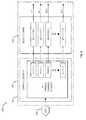
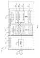
- a simplified block diagramshows an example radio receiver physical layer 122 .
- the radiomay be used for any desired purpose, such as communication with the plurality of endpoints 108 - 120 .
- An RF subsystem or front end 124may provide an analog signal covering an entire radio band to a digital subsystem 126 .
- the analog signalmay be provided in the time domain.
- An analog to digital converter (ADC) 128may be in the RF subsystem 124 , the digital subsystem 126 or between the two.
- ADCanalog to digital converter
- ADC 128ADC 128
- FPGA 130a field programmable gate array 130
- ASICapplication specific integrated circuit
- DSPdigital signal processor
- the digital subsystem 126receives a down-converted and filtered signal from RF subsystem 124 , which contains information representative of an entire radio band of interest. Filtering provided by the RF subsystem 124 attenuates signals outside the radio band to prevent any aliased products from interfering with the targeted received signals.
- the digital subsystem 126may sample intermediate frequency (IF) signals provided by RF subsystem 124 and perform calculations to create parallel RF channels of incoming signal data.
- IFintermediate frequency
- ADC 128converts the analog signal into a sampled digital representation.
- the FPGA 130receives the digital representation, and channelizes and re-samples it into discrete channels.
- the FPGA 130may also provide a correlating detector to identify known preamble signatures (e.g., a synchronization word (or sync-word)) in an incoming data packet to identify and validate the data packet.
- the decoding capability of the digital subsystem 126(which may be located in FPGA 130 ) detects, identifies, modulates and/or demodulates multiple modulation schemes, e.g., on-off keying (OOK) and/or GFSK modulation. Once correlation is achieved, FPGA 130 then decodes raw samples into bits and passes words (e.g., 16-bit words) to DSP processor 134 .
- the DSP 134provides packet decoding, cyclic redundancy code (CRC) validation, and if available, forward error correction (FEC) for each successfully detected packet.
- CRCcyclic redundancy code
- FECforward error correction
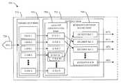
- FIG. 2illustrates an example implementation of a digital subsystem 226 of a radio receiver (such as digital subsystem 126 of FIG. 1 ).
- an ADC 228may convert an analog signal into a digital representation that is passed to channelizer bank 250 of a logic device 230 (e.g., an FPGA).
- Channelizer bank 250channelizes and resamples the digital signal into parallel paths aligned with discrete channels 1 -N.
- Each channel of channels 1 -Nconnects to a respective decoder 1 -N of a decoder bank 252 in a one-to-one mapping of channels to decoders.
- Each decodermay perform detection, identification, and modulation and/or demodulation of one or more multiple modulation schemes.
- raw samplesmay be decoded into bits and words (e.g., 16-bit words) and may be passed to a DSP (not shown) as described above.
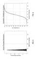
- FIGS. 3 and 4show the results of a simulation that show that only a small subset of channels may be active at any given instant. In the simulation, the following parameters were used:
- FIG. 3shows the relative distribution of channels that were receiving a packet at any given instant. Even though there were 476 channels available, on average only 7.4 channels were active at any given instant, with a standard deviation of 2.7 channels.
- FIG. 4shows the cumulative distribution function (CDF) of this simulation. The results of the simulation show that 99.7% of the time, approximately 15.5 channels are receiving a signal. The simulation also showed that 0.78% of the packets were lost due to collisions (not shown). Therefore, even though there are 476 receiving channels, less than 16 channels (and, therefore, less than 16 decoders) were active 99.7% of the time.
- CDFcumulative distribution function
- FIGS. 5 and 6show the results of a similar simulation that further confirms the above results.
- the same parameter valueswere used, except that the number of endpoints was increased to 1 million (10 times greater than in the previous simulation). In many types of RF networks, this would likely be considered an extreme case that would rarely, if ever, occur.
- the results of this simulationwere as follows:
- Typical decoderscontain blocks for, for example but not limitation, data packet identification (e.g., sync-word detection), automatic frequency correction (AFC), automatic gain control (AGC), channel filtering, bit detection, data de-whitening, convolutional decoding, etc.
- data packet identificatione.g., sync-word detection
- AFCautomatic frequency correction
- AGCautomatic gain control
- channel filteringbit detection
- bit detectiondata de-whitening
- convolutional decodingetc.
- the amount of power and quantity of components (e.g., fabric) associated with the data packet identification blockis typically small relative to other blocks found in a decoder.
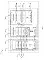
- FIGS. 7-9are block diagrams representative of example implementations of radio receivers with efficient decoder usage, according to embodiments of the present disclosure.
- an example receiver 700may include an ADC 728 and a logic device 730 (e.g., an FPGA) that may include a channelizer bank 750 and a decoder bank 752 .
- Channelizer bank 750may include pathway(s) that align with discrete channels 1 -N. While these pathways may be implemented as multiple parallel pathways, the receiver embodiments described herein may be implemented as including either true parallel paths, or effectively parallel paths realized by interleaving into a single data path, or both.
- Decoder bank 752may comprise two different banks—a data packet identification bank 758 including data packet identification blocks 1 -N that correspond to channel pathways 1 -N, and a remaining decoder blocks bank 760 that includes decoder blocks 1 -M, where M is less than N.
- the number of decoder blocksis less than the number of data packet identification blocks, where the number of decoder blocks is optimized. This optimization may be based on one or more goals, including one or more of, for example but not limitation, reduced power consumption, reduced component cost, reduced number of components used, minimized packet loss, etc.
- the determination of an optimal number M of decoder blocksmay be accomplished by analyzing results of a previously run simulation based on parameters relevant to accomplishing the desired goal(s). One example of such a simulation is the simulation described above.
- channelizer bank 750may channelize and resample a digital signal from ADC 728 into path(s) aligned with discrete channels 1 -N.
- Each channel of channels 1 -Nmay connect to a respective data packet identification block 1 -N of data packet identification bank 758 in a one-to-one mapping of channels to identification banks.
- the data packet identification blocke.g., a sync-word detector
- the decoder blockmay perform one or more decoding functions (e.g., automatic frequency correction (AFC), automatic gain control (AGC), channel filtering, bit detection, data de-whitening, convolutional decoding, etc.), as would be understood by one of ordinary skill in the relevant art.
- AFCautomatic frequency correction
- AGCautomatic gain control
- channel filteringbit detection
- data de-whiteningconvolutional decoding
- the decoder functions performedmay depend on what is specified in the detected sync-word.
- one or more data packet identification blocksmay comprise one or more sub-identification blocks.
- ID BLK 4is comprised of sub-identification blocks ID BLK 4 a and ID BLK 4 b .
- Sub-identification blocksmay be used for various reasons. For example, sub-identification blocks may be used when more than one sync-word is used to identify and/or classify an incoming data packet. Differing sync-words may be used to provide further information regarding a packet (e.g., to identify a packet, to identify packet priority processing, to define what decoder functionality is needed, etc.). In the example shown in FIG.
- a single data packetmay be identified and/or classified via ID BLKs 4 a and 4 b and passed onto a decoder block (here, DECODER BLK 1 ).
- the decoder functions performedmay depend on what is specified in the detected sync-word(s). In this example, where only one single data packet is validated by a data packet identification block at a time, for optimization purposes, a data packet identification block is counted as one in the count of data packet identification blocks for determining the number of decoder blocks needed, no matter how many sub-identification blocks it may have.
- FIG. 8depicts an example receiver 800 according to an embodiment where one or more data packet identification blocks may comprise one or more sub-identification blocks that may each be able to handle separate data packets simultaneously or in an overlapping manner.
- sub-identification blocksmay be used to validate one or more packets that come in on a channel in a discrete serial manner as described above, in an overlapping manner, or simultaneously.
- an example receiver 800may include an ADC 828 and a logic device 830 (e.g., an FPGA) that may include a channelizer bank 850 and a decoder bank 852 .
- Channelizer bank 850may include pathway(s) that align with discrete channels 1 -N.
- Decoder bank 852may comprise two different banks—a data packet identification bank 858 including data packet identification blocks 1 -N that correspond to channel pathways 1 -N, and a remaining decoder blocks bank 860 that includes decoder blocks 1 -M, where M is less than a total number of sub-identification blocks.
- a data packet identification blockcomprises just one block, for optimization purposes, it may be considered a single sub-identification block in the count of sub-identification blocks for determining how many decoder blocks are needed. Similar to the embodiment shown in FIG.
- the number of decoder blocksis less than the number of total sub-identification blocks, where the number of decoder blocks is optimized. This optimization may be based on one or more goals, as discussed above.
- the determination of an optimal number M of decoder blocksmay be accomplished by analyzing results of a previously run simulation based on parameters relevant to accomplishing the desired goal(s), as also discussed above.
- channelizer bank 850may channelize and resample a digital signal from ADC 828 into path(s) aligned with discrete channels 1 -N.
- Each channel of channels 1 -Nmay connect to a respective data packet identification block 1 -N of data packet identification bank 858 in a one-to-one mapping of channels to identification banks.
- channel 2may connect (and therefore provide a signal, or multiple signals, coming in on channel 2 ) to data packet identification block 2 (shown as block 862 ).
- Data packet identification block 2 in this examplecomprises two sub-identification blocks 2 a and 2 b (e.g., sync-word detectors) that may detect, identify, and ultimately validate (e.g., if one of the two sub-identification blocks 2 a and 2 b recognizes the packet's sync-word) one or two (e.g., overlapping or simultaneously) received data packets from the signal. If a third packet arrives before sub-identification block 2 a or 2 b finish validating a packet, the third packet may be lost. The validated data packet(s) may be provided to respective available decoder block(s) of the remaining decoder blocks bank 860 .
- two sub-identification blocks 2 a and 2 be.g., sync-word detectors
- each of two validated data packetsare respectively provided from ID BLK 2 b and ID BLK 2 a to DECODER BLK 1 and DECODER BLK 2 .
- DECODER BLKs 1 and 2may perform one or more decoding functions (e.g., automatic frequency correction (AFC), automatic gain control (AGC), channel filtering, bit detection, data de-whitening, convolutional decoding, etc.), as would be understood by one of ordinary skill in the relevant art.
- the decoder functions performedmay depend on what is specified in the detected sync-word(s).
- DECODER BLKs 1 and 2each complete their processing, resulting bits and words (e.g., 16-bit words) may be passed to a DSP (not shown), as would be understood by one of ordinary skill in the relevant art, and DECODER BLKs 1 and 2 would become available for other validated data packets.
- DSPdigital signal processor
- DECODER BLKs 1 and 2would become available for other validated data packets.
- the data packetmay be lost.
- By optimizing the number of decoder blockse.g., via simulation), data packet loss can be minimized, as discussed previously.
- the embodiments shown in FIGS. 7 and 8are just two examples of receivers including an optimized decoder bank as disclosed herein. Other examples may be contemplated as would be understood by those of ordinary skill in the art after reading this disclosure. For example, embodiments may include combinations of the features described above with reference to FIGS. 7 and 8 .
- the data packet identification bankmay include both data packet identification blocks that are comprised of sub-identification blocks that may validate a single data packet (as described with reference to FIG. 7 ) and sub-identification blocks that may validate two or more data packets received in a discrete serial manner, overlapping, or simultaneously (as described with reference to FIG. 8 ).
- data packet identification blocks that have sub-identification blocks but only validate one single data packet at a timemay be counted as one in the determination of how many decoder blocks are needed, while data packet identification blocks that have sub-identification blocks and can validate more than one data packet at a time may count as however many sub-identification blocks it contains (i.e., each sub-identification block counts separately in the determination of how many decoder blocks are needed).
- FIG. 9depicts an example receiver 900 according to an embodiment having only a single channel.
- an example receiver 900may include an ADC 928 and a logic device 930 (e.g., an FPGA) that may include a channelizer bank 950 (which in this example includes a single channel 964 ) and a decoder bank 952 .
- a logic device 930e.g., an FPGA
- Decoder bank 952may comprise two different banks—a data packet identification bank 958 including a single data packet identification block 966 having data packet sub-identification blocks 1 - 1 to 1 -N, and a remaining decoder blocks bank 960 that includes decoder blocks 1 -M, where M is less than a total number of data packet sub-identification blocks.
- the number of decoder blocksis less than the number of total data packet sub-identification blocks, where the number of decoder blocks is optimized. This optimization may be based on one or more goals, as discussed above.
- the determination of an optimal number M of decoder blocksmay be accomplished by analyzing results of a previously run simulation based on parameters relevant to accomplishing the desired goal(s), as also discussed above.
- multiple signalsi.e., multiple data packets
- This embodimentmay be useful where there may be a common modulation mode with different spreading factors using orthogonal codes.
- channelizer bank 950may channelize and resample a digital signal or signals from ADC 928 into a path aligned with channel 964 .
- Channel 964may connect to data packet identification block 966 of data packet identification bank 958 .
- channel 964may connect (and therefore provide one or more data packets coming in on channel 964 ) to data packet identification block 966 .
- Data packet identification block 966 in this examplecomprises N sub-identification blocks 1 - 1 to 1 -N (e.g., sync-word detectors) that may detect, identify, and ultimately validate one or more (up to N) data packets received discretely in serial, overlapping, or simultaneously from the signal(s) and provide the validated data packets to one or more respective available decoder blocks of the remaining decoder blocks bank 960 . If all N sub-identification blocks are in use and a packet N+1 arrives before sub-identification blocks 1 -N finish validating their respective packet, packet N+1 may be lost.
- N sub-identification blocks 1 - 1 to 1 -Ne.g., sync-word detectors
- validated data packetsare provided to DECODER BLK 1 from sub-identification block 1 - 2 and to DECODER BLK 3 from sub-identification block 1 - 1 .
- the DECODER BLKs 1 , 3may each perform one or more decoding functions (e.g., automatic frequency correction (AFC), automatic gain control (AGC), channel filtering, bit detection, data de-whitening, convolutional decoding, etc.), as would be understood by one of ordinary skill in the relevant art.
- AFCautomatic frequency correction
- AGCautomatic gain control
- channel filteringbit detection
- bit detectiondata de-whitening
- convolutional decodingetc.
- DECODER BLKs 1 , 3complete their processing, resulting bits and words (e.g., 16-bit words) may be passed to a DSP (not shown), as would be understood by one of ordinary skill in the relevant art, and each of DECODER BLKs 1 , 3 would become available for other validated data packets.
- a DSPnot shown
- each of DECODER BLKs 1 , 3would become available for other validated data packets.
- the data packetmay be lost.
- By optimizing the number of decoder blockse.g., via simulation), data packet loss can be minimized, as discussed previously.
- FIGS. 10-13are flow charts representative of example processes that may be implemented for receiving data packets, according to embodiments of the present disclosure.
- Method 1000 of FIG. 10corresponds to the embodiment shown and described with reference to FIG. 7 .
- a data packetmay be received at a channel receiver of at least one channel receiver each associated with a channel (block 1002 ).
- the data packetmay be provided to a data packet identification block (of at least two data packet identification blocks, or of at least one data packet identification block where at least one data packet identification block includes two or more sub-identification blocks) that corresponds to the channel receiver (block 1004 ).
- the data packetmay be validated at the data packet identification block (block 1006 ).
- the validated data packetmay be provided to an available decoder block of at least one decoder block capable of performing desired decoding functions (block 1008 ).
- the available decoder block the data packet is provided tomay be a first available decoder block, for example, that may be determined in any number of ways (e.g., arbitrarily, according to a predetermined order, according to a prioritization algorithm, etc.).
- the quantity of decoder blocksmay be optimized according to one or more goals (e.g., reduced power consumption, reduced component cost, reduced number of components used, minimized packet loss, etc.), such that there are less decoder blocks needed than the number of data packet identification blocks (i.e., a one-to-one correspondence of data packet identification blocks to decoder blocks is not needed).
- the optimization regarding the number of decoder blocks neededmay be determined by, for example, a previously performed simulation. An example of such simulation was provided above.
- Method 1100 of FIG. 11corresponds to the embodiment shown and described with reference to FIG. 8 .
- a data packetmay be received at a channel receiver of at least one channel receiver each associated with a channel (block 1102 ).
- the data packetmay be provided to a data packet identification block that corresponds to the channel receiver, the data packet identification block being of at least one data packet identification block where at least one data packet identification block includes two or more sub-identification blocks (block 1104 ).
- the data packetmay be validated at the data packet identification block (block 1106 ).
- the validated data packetmay be provided to an available decoder block of at least one decoder block capable of performing desired decoding functions, where a quantity of the decoder blocks is less than a quantity of the sub-identification blocks (block 1108 ).
- the available decoder block the data packet is provided tomay be a first available decoder block, for example, that may be determined in any number of ways (e.g., arbitrarily, according to a predetermined order, according to a prioritization algorithm, etc.).
- the quantity of decoder blocksmay be optimized according to one or more goals (e.g., reduced power consumption, reduced component cost, reduced number of components used, minimized packet loss, etc.), such that there are less decoder blocks needed than the number of data packet identification blocks (i.e., a one-to-one correspondence of data packet identification blocks to decoder blocks is not needed).
- the optimization regarding the number of decoder blocks neededmay be determined by, for example, a previously performed simulation. An example of such simulation was provided above.
- FIG. 12is a flow diagram 1200 that continues the methodology shown in FIGS. 10 and/or 11 , according to an embodiment of the present disclosure.
- the validated data packetmay be processed at the available decoder block, making the available decoder block unavailable to other validated data packets (block 1202 ).
- the validated data packetmay be released by the decoder block as a decoded data packet (block 1204 ).
- the unavailable decoder blockmay then be released, making it available to other validated data packets (block 1206 ).
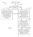
- FIG. 13is a flow diagram 1300 that continues the methodology shown in FIGS. 10 and/or 11 , according to an embodiment of the present disclosure. From block 1008 of FIG. 10 or block 1108 of FIG. 11 , it may be determined if a decoder block is available (block 1302 ). If a decoder block is available, the validated data packet may be provided to and processed at the available decoder block, making the available decoder block unavailable to other validated data packets. Upon completion of processing the validated data packet, the validated data packet may be released by the decoder block as a decoded data packet (block 1306 ). The unavailable decoder block may then be released, making it available to other validated data packets (block 1308 ).
- a decoder block that is processing a lower priority data packetmay be forced to stop processing the lower priority data packet and become available (block 1310 ) to process the higher priority data packet.
- a data packetmay be identified as a higher priority data packet in a number of ways (e.g., its having been received on a higher priority channel, its having preamble (e.g., sync-word) data that includes an indication that the data packet is a higher priority data packet, etc.).
- an endpoint alarm(e.g., an identification of a problem at a utility meter), may use or include a different sync-word than a regular data packet that includes meter reading data, for example.
- the higher priority alarm packetmay “trump” a regular packet in the decoder bank if all of the decoders are being used.
- a hierarchy of prioritymay be used that includes two or more priority levels. Methodology 1300 may continue at block 1304 with the now available decoder block to process the higher priority data packet instead.
- all of the decoder blocksmay have identical decoding functionality (e.g., a superset of functionality), and it would not matter which decoder block was to process a validated data packet because any of them may be used.
- one or more decoder blocksmay be capable of having one or more functions enabled or disabled depending on the packet. The enabling or disabling of decoder block functionality for a specific packet may be indicated based on, for example, the channel on which the packet came in, an indication in a packet's sync-word, etc.
- one or more decoder blocksmay be capable of performing one or more different sets of decoding functions than one or more other decoder blocks, and the determination to which decoder block to provide a validated data packet may depend on which functions each decoder block may be capable of performing.
- a data packet coming in through a certain channele.g., channel 4
- a decoding functionthat only decoder blocks 5 - 10 (not explicitly shown) can provide.
- decoder blocks 5 - 10when that data packet is received via channel 4 , and identified at data packet identification block 4 , its pool of possible decoder blocks may be determined to be limited to decoder blocks 5 - 10 , even if any of decoder blocks 1 - 4 and 11 -N are available. Limiting the decoder functionality of the decoder blocks may further reduce power consumption and/or component cost, though at a cost of reduced availability and possible loss of packets. Determining an efficient configuration of decoder blocks and their functionality capabilities may be accomplished using a previously conducted simulation, depending on needs and/or goals.
- One or more features disclosed hereinmay be implemented in hardware, software, firmware, and/or combinations thereof, including discrete and integrated circuit logic, application specific integrated circuit (ASIC) logic, and microcontrollers, and may be implemented as part of a domain-specific integrated circuit package, or a combination of integrated circuit packages.
- the terms software and firmware, as used herein,refer to a computer program product including at least one computer readable medium having computer program logic, such as computer-executable instructions, stored therein to cause a computer system to perform one or more features and/or combinations of features disclosed herein.
- the computer readable mediummay be transitory or non-transitory.
- An example of a transitory computer readable mediummay be a digital signal transmitted over a radio frequency or over an electrical conductor, through a local or wide area network, or through a network such as the Internet.
- An example of a non-transitory computer readable mediummay be a compact disk, a flash memory, SRAM, DRAM, a hard drive, a solid state drive, or other data storage device.
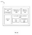
- FIG. 14is a block diagram of a processing platform 1400 that may be capable of controlling a receiver, such as the receivers shown in FIGS. 7, 8, and 9 , according to embodiments of this disclosure.
- the processing platformmay be embodied in any type of mobile or non-mobile computing device.
- mobile devicesmay include, but are not to be limited to, laptop computers, ultra-laptop computers, tablets, touch pads, portable computers, handheld computers, palmtop computers, personal digital assistants (PDAs), e-readers, cellular telephones, combination cellular telephone/PDAs, mobile smart devices (e.g., smart phones, smart tablets, etc.), mobile internet devices (MIDs), mobile messaging devices, mobile data communication devices, mobile media playing devices, cameras, mobile gaming consoles, wearable devices, etc.
- PDAspersonal digital assistants
- MIDsmobile internet devices
- non-mobile devicesmay include, but are not to be limited to, servers, personal computers (PCs), Internet appliances, televisions, smart televisions, data communication devices, media playing devices, gaming consoles, etc.
- processing platform 1400may be embodied in the data collector 106 of FIG. 1 . Similar processing platforms may be embodied in endpoints 108 - 120 , the computing devices at central office 102 , and/or a mobile collection device.
- Processing platform 1400may include one or more processors 1480 , memory 1482 , one or more secondary storage devices 1484 , one or more input/output devices 1486 , and/or one or more communication interfaces 1488 , in communication via a bus, line, or similar implementation (not shown).
- Processor(s) 1480may be implemented by, for example but not limitation, one or more integrated circuits, logic circuits, microprocessors, controllers, etc.
- Processor(s) 1480may include a local memory 1490 (e.g., a cache).
- Memory 1482may include a volatile and/or a non-volatile memory.
- Volatile memorymay be implemented by, for example but not limitation, Synchronous Dynamic Random Access Memory (SDRAM), Dynamic Random Access Memory (DRAM), RAMBUS Dynamic Random Access Memory (RDRAM) and/or any other type of random access memory device.
- Non-volatile memorymay be implemented by flash memory and/or any other desired type of memory device. Access to memory 1482 may be controlled by a memory controller (not shown). Data stored in local memory 1490 and/or memory 1482 may be used by processor(s) 1480 to facilitate the controlling of a receiver, such as the receivers shown in FIGS. 7, 8, and 9 , according to embodiments of this disclosure.
- Input/output devices 1486may allow a user to interface with processor(s) 1480 .
- Input devicesmay allow a user to enter data and/or commands for processor(s) 1480 .
- Input devicesmay include, for example, an audio sensor, a microphone, a camera (e.g., still, video, etc.), a keyboard, a button, a mouse, a touchscreen, a track-pad, a trackball, isopoint, a voice recognition system, etc.
- Output devicesmay provide or present information to a user.
- Output devicesmay include, for example, display devices (e.g., a light emitting diode (LED), an organic light emitting diode (OLED), a liquid crystal display, a cathode ray tube display (CRT), a touchscreen, a tactile output device, a printer, speakers, etc.).
- the input/output devices 1486may be connected to processor(s) 1480 , for example, with an interface circuit (not shown).
- the interface circuitmay be implemented by any type of interface standard, such as, for example, an Ethernet interface, a universal serial bus (USB), a PCI express interface, etc.
- the interface circuitmay include a graphics driver card, chip, and/or processor.
- Communication interface(s) 1488may be implemented in hardware or a combination of hardware and software, and may provide wired or wireless network interface(s) to one or more networks, such as network(s) 104 of FIG. 1 .
- Communication interface(s) 1488may be a part of, or connected with, the interface circuit discussed above, and/or may include or connect with communication devices such as a transmitter, a receiver, a transceiver, a modem and/or network interface card to facilitate exchange of data with external devices (e.g., computing devices of any kind) via a network, such as the RF network described in this disclosure.
- Secondary storage device(s) 1484may store processing logic 1492 (e.g., software) to be executed by processor(s) 1480 and/or data 1494 .
- Processing logic 1492 and data 1494may be used by processor(s) 1480 to facilitate the controlling of a receiver, such as the receivers shown in FIGS. 7, 8, and 9 , according to embodiments of this disclosure.
- Processing logic 1492may include instructions for executing the methodology shown in FIGS. 10-13 , for example.
- Examples of secondary storage device(s) 1484may include one or more hard drive disks, compact disk (CD) drives, digital versatile disk (DVD) drives, Blu-ray disk drives, redundant array of independent disks (RAID) systems, floppy disk drives, flash drives, etc.
- Data and/or processing logicmay be stored on a removable tangible computer readable storage medium (e.g., a floppy disk, a CD, a DVD, a Blu-ray disk, etc.) using one or more of the secondary storage device(s) 1484 .
- a removable tangible computer readable storage mediume.g., a floppy disk, a CD, a DVD, a Blu-ray disk, etc.
- the technology disclosed hereinallows for a large multi-channel receiver to be efficiently implemented with minimal to no data packet loss while significantly reducing the use of expensive components (e.g., FPGA resources, etc.), reducing the number of components (and also the space needed for them), and reducing power dissipation. This is accomplished by optimizing the decoder bank and how it is used.
- the disclosed architecturesprovide designs scalable depending on desired goals (e.g., minimized data packet loss, component cost savings, power savings, space savings, etc.).
- the goals discussed hereinare just a few examples of the many goals that may be contemplated and effected using the disclosed technology.
Landscapes
- Engineering & Computer Science (AREA)
- Computer Networks & Wireless Communication (AREA)
- Signal Processing (AREA)
- Mobile Radio Communication Systems (AREA)
Abstract
Description
- Number of endpoints in a cell: 100,000
- Number of channels: 476
- Transmission (TX) packet length: 400 msec
- Bubble-up rate: 90 minutes
- Time dithering: 100 msec
The bubble-up rate refers to how often an endpoint turns on to provide data. Time dithering refers to forcing random transmission start time to vary for a given bubble-up rate to prevent data collisions due to simultaneous data packet transmissions. The following summarizes the results of the simulation: - Average active channels: 7.4
- Standard deviation: 2.7
- Number of collisions: 11,650 (0.78%)
and the data is plotted inFIGS. 3 and 4 .
- Average active channels: 68.6
- Standard deviation: 7.6
- Number of collisions: 1,109,807 (7.4%)
and the data is plotted inFIGS. 5 and 6 . By substantially increasing the number of endpoints, many more packets were lost due to collisions. With a collision rate of 7.4%, the RF spectrum may begin to hit the limits of practical deployment. Even in this extreme scenario, however, the average number of active channels was only 68.6 with a standard deviation of 7.6, which indicates that less than 92 decoders were active 99.7% of the time.
Claims (24)
Priority Applications (3)
| Application Number | Priority Date | Filing Date | Title |
|---|---|---|---|
| US14/879,262US9992124B2 (en) | 2015-10-09 | 2015-10-09 | Multi-channel decoder architecture |
| CA2944296ACA2944296C (en) | 2015-10-09 | 2016-10-05 | Multi-channel decoder architecture |
| EP16192918.7AEP3154204B1 (en) | 2015-10-09 | 2016-10-07 | Multi-channel decoder architecture |
Applications Claiming Priority (1)
| Application Number | Priority Date | Filing Date | Title |
|---|---|---|---|
| US14/879,262US9992124B2 (en) | 2015-10-09 | 2015-10-09 | Multi-channel decoder architecture |
Publications (2)
| Publication Number | Publication Date |
|---|---|
| US20170104684A1 US20170104684A1 (en) | 2017-04-13 |
| US9992124B2true US9992124B2 (en) | 2018-06-05 |
Family
ID=57442429
Family Applications (1)
| Application Number | Title | Priority Date | Filing Date |
|---|---|---|---|
| US14/879,262Expired - Fee RelatedUS9992124B2 (en) | 2015-10-09 | 2015-10-09 | Multi-channel decoder architecture |
Country Status (3)
| Country | Link |
|---|---|
| US (1) | US9992124B2 (en) |
| EP (1) | EP3154204B1 (en) |
| CA (1) | CA2944296C (en) |
Cited By (1)
| Publication number | Priority date | Publication date | Assignee | Title |
|---|---|---|---|---|
| US20190089373A1 (en)* | 2018-11-20 | 2019-03-21 | Intel Corporation | Multi-channel decoder with distributed scheduling |
Families Citing this family (5)
| Publication number | Priority date | Publication date | Assignee | Title |
|---|---|---|---|---|
| US9992124B2 (en)* | 2015-10-09 | 2018-06-05 | Itron, Inc. | Multi-channel decoder architecture |
| US10614237B2 (en) | 2017-11-10 | 2020-04-07 | International Business Machines Corporation | Resource-free prioritizing in high availability external security systems |
| US10389486B1 (en)* | 2018-10-05 | 2019-08-20 | Cypress Semiconductor Corporation | Parallel processing of dirty packets in Bluetooth and Bluetooth low energy systems |
| US11930244B2 (en)* | 2019-11-23 | 2024-03-12 | Dish Network Technologies India Private Limited | Method and apparatus for preview decoding for joint video production |
| CN117560132B (en)* | 2024-01-10 | 2024-04-02 | 航天科工空间工程网络技术发展(杭州)有限公司 | A channelized receiver and receiving method based on reverse channel time synchronization |
Citations (145)
| Publication number | Priority date | Publication date | Assignee | Title |
|---|---|---|---|---|
| US4455649A (en) | 1982-01-15 | 1984-06-19 | International Business Machines Corporation | Method and apparatus for efficient statistical multiplexing of voice and data signals |
| US5377227A (en) | 1992-09-09 | 1994-12-27 | Echelon Corporation | Adaptive data recovery for spread spectrum systems |
| US5408524A (en)* | 1993-03-29 | 1995-04-18 | Xel Communications, Inc. | Answer supervision over pulse code modulated carrier system and method therefore |
| WO1995028041A1 (en) | 1994-04-08 | 1995-10-19 | Echelon Corporation | Apparatus and method for detecting a signal in a communications system |
| US5577031A (en) | 1995-03-22 | 1996-11-19 | Smith; Jeffrey W. | Wideband channelizer incorporating diversity switch |
| US5809422A (en) | 1996-03-08 | 1998-09-15 | Watkins Johnson Company | Distributed microcellular communications system |
| US5815117A (en)* | 1997-01-02 | 1998-09-29 | Raytheon Company | Digital direction finding receiver |
| US5832249A (en) | 1995-01-25 | 1998-11-03 | Advanced Micro Devices, Inc. | High performance superscalar alignment unit |
| US5920589A (en) | 1995-06-07 | 1999-07-06 | Sanconix Inc. | Direct sequence spread spectrum DSP system |
| US5991349A (en)* | 1997-06-18 | 1999-11-23 | Winbond Electronics Corp. | Data processing device |
| EP1024621A2 (en) | 1999-01-29 | 2000-08-02 | TRW Inc. | Buffering and sequencing of soft decisions of multiple channels into a single shared biorthogonal decoder |
| US6128276A (en)* | 1997-02-24 | 2000-10-03 | Radix Wireless, Inc. | Stacked-carrier discrete multiple tone communication technology and combinations with code nulling, interference cancellation, retrodirective communication and adaptive antenna arrays |
| US6141373A (en) | 1996-11-15 | 2000-10-31 | Omnipoint Corporation | Preamble code structure and detection method and apparatus |
| US6205319B1 (en)* | 1998-09-18 | 2001-03-20 | Trw Inc. | Dual phased-array payload concept |
| US6230026B1 (en)* | 1998-10-15 | 2001-05-08 | Airnet Communications Corporation | Basestation architecture supporting baseband frequency hopping utilizing time division multiplexed mapping between a radio transceiver and digital signal processing resources |
| US6253060B1 (en) | 1996-12-20 | 2001-06-26 | Airnet Communications Corporation | Method and apparatus employing wireless remote loopback capability for a wireless system repeater to provide end-to-end testing without a wireline connection |
| US6282184B1 (en)* | 1997-12-22 | 2001-08-28 | Nortel Networks Limited | Common digitizing rate for multiple air interfaces for generic cell sites in cellular radio |
| US6339694B1 (en) | 1998-03-30 | 2002-01-15 | Airnet Communications Corporation | Method and apparatus employing automatic RF muting and wireless remote control of RF downlink transmission for a wireless repeater |
| US6347120B1 (en) | 1997-08-07 | 2002-02-12 | Sony Corporation | Communication method, transmitter, receiver, and cellular radio communication system |
| US20020090915A1 (en) | 2000-01-10 | 2002-07-11 | Komara Michael A. | Method and apparatus for equalization in transmit and receive levels in a broadband transceiver system |
| US20020106009A1 (en) | 2000-12-01 | 2002-08-08 | Motorola, Inc. | Methods and apparatus for transmultiplexing a multi-channel signal |
| US20020118784A1 (en) | 2000-12-26 | 2002-08-29 | Nortel Networks Limited | Apparatus and method to provide spectrum sharing for two or more RF signals occupying an overlapping RF bandwidth |
| US6445685B1 (en) | 1999-09-29 | 2002-09-03 | Trw Inc. | Uplink demodulator scheme for a processing satellite |
| US20020188723A1 (en) | 2001-05-11 | 2002-12-12 | Koninklijke Philips Electronics N.V. | Dynamic frequency selection scheme for IEEE 802.11 WLANs |
| US6526532B1 (en) | 1998-11-06 | 2003-02-25 | Telefonaktiebolaget Lm Ericsson (Publ) | Channel error correction apparatus and method |
| US6535502B1 (en) | 1998-06-30 | 2003-03-18 | Agere Systems Inc. | Pilot symbols |
| US20030060204A1 (en) | 2001-09-27 | 2003-03-27 | Francl Michael J. | Method for autonomous frequency management for reliable data communications |
| US20030076899A1 (en) | 2001-10-18 | 2003-04-24 | The Aerospace Corporation | Polyphase channelization system |
| US20040032825A1 (en) | 2002-08-19 | 2004-02-19 | Halford Steven D. | Wireless receiver for sorting packets |
| US20040042557A1 (en)* | 2002-08-29 | 2004-03-04 | Kabel Allan M. | Partial band reconstruction of frequency channelized filters |
| US20040152418A1 (en) | 2002-11-06 | 2004-08-05 | Engim, Inc. | Unified digital front end for IEEE 802.11g WLAN system |
| US6798850B1 (en) | 1999-02-26 | 2004-09-28 | Telefonaktiebolaget Lm Ericsson (Publ) | Method and arrangement in a radio receiver system with several standards |
| US6798853B1 (en) | 2000-11-15 | 2004-09-28 | Telefonaktiebolaget Lm Ericsson (Publ) | System and method for compensating for frequency offset |
| US20040246994A1 (en) | 2003-06-09 | 2004-12-09 | Munoz Michael Steven | Efficient and flexible oversampled filterbank with near perfect reconstruction constraint |
| US6830523B1 (en) | 2004-01-28 | 2004-12-14 | 2Xj Enterprises, Inc. | Mechanical broadhead arrowhead |
| US20050005225A1 (en)* | 2003-06-13 | 2005-01-06 | The Regents Of The University Of California | Fade-resistant forward error correction method for free-space optical communications systems |
| US6850774B1 (en) | 1995-06-07 | 2005-02-01 | Cirrus Logic, Inc. | Portable communications and data terminal operating to optimize receipt of both incoming CDPD and AMPS messages |
| US20050122895A1 (en) | 2003-12-05 | 2005-06-09 | Xu Zhou | Residual frequency error estimation in an OFDM receiver |
| US6910979B2 (en) | 2000-03-13 | 2005-06-28 | Bruce Barrie | Expandable broadhead |
| US20050156775A1 (en) | 2003-05-12 | 2005-07-21 | Peter Petre | Adaptive, intelligent transform-based analog to information converter method and system |
| US6935976B1 (en) | 2003-11-12 | 2005-08-30 | G5 Outdoors, L.L.C. | Mechanical broadhead with sliding blades |
| US20050201450A1 (en) | 2004-03-03 | 2005-09-15 | Volpi John P. | Interrogator and interrogation system employing the same |
| US20050259724A1 (en) | 2004-05-24 | 2005-11-24 | Bergstrom Chad S | Method and apparatus for signal separation |
| US20050259755A1 (en) | 2002-09-09 | 2005-11-24 | Koninklijke Philips Electronics, N.V. | Fliterbank modulation system with pre-equalization |
| US20050281321A1 (en) | 2004-06-17 | 2005-12-22 | Bergstrom Chad S | Method and apparatus for distributed polyphase spread spectrum communications |
| US20050289623A1 (en) | 2004-05-21 | 2005-12-29 | Mowaffak Midani | Bulk tuning of frequency-modulated video signals |
| US7091854B1 (en) | 2004-04-09 | 2006-08-15 | Miao George J | Multiple-input multiple-output wireless sensor networks communications |
| US20070067376A1 (en) | 2005-09-19 | 2007-03-22 | Noga Andrew J | Complimentary discrete fourier transform processor |
| US20070069864A1 (en) | 2005-09-29 | 2007-03-29 | Ji-Hoon Bae | Apparatus and method for receiving tag signal in mobile RFID reader |
| US20070097942A1 (en) | 2005-10-27 | 2007-05-03 | Qualcomm Incorporated | Varied signaling channels for a reverse link in a wireless communication system |
| US7248189B2 (en) | 2002-11-06 | 2007-07-24 | Edgewater Computer Systems, Inc. | Programmable sample rate conversion engine for wideband systems |
| US20070286311A1 (en)* | 2006-05-01 | 2007-12-13 | Coyne Paul T | Communications system comprising channelized receiver |
| US20070291829A1 (en) | 2006-06-12 | 2007-12-20 | Kabushiki Kaisha Toshiba | Wireless communication apparatus and transmission control method |
| US20080001779A1 (en) | 2004-03-30 | 2008-01-03 | Itron Inc. | Frequency Shift Compensation, Such as for Use In a Wireless Utility Meter Reading Environment |
| WO2008018755A1 (en) | 2006-08-08 | 2008-02-14 | Electronics And Telecommunications Research Institute | Method for managing multple frequency assignment using terminal's received performance in ofdma wran system |
| US20080233954A1 (en) | 2007-03-19 | 2008-09-25 | Brima Ibrahim | Method And System For Processing Results Derived From Detecting Channels Suitable For FM Transmission In An Integrated FM Transmit/Receive System |
| US7430254B1 (en) | 2003-08-06 | 2008-09-30 | Lockheed Martin Corporation | Matched detector/channelizer with adaptive threshold |
| US7466743B2 (en) | 2001-09-12 | 2008-12-16 | Infineon Technologies Ag | CDMA wireless systems |
| US7483483B2 (en) | 2001-12-06 | 2009-01-27 | Pulse-Link, Inc. | Ultra-wideband communication apparatus and methods |
| WO2009055770A1 (en) | 2007-10-26 | 2009-04-30 | Hunt Technologies, Llc | Programmable signal slicer |
| US20090131113A1 (en) | 2006-08-18 | 2009-05-21 | Fujitsu Limited | Base station apparatus and reception processing method thereof |
| US7548579B1 (en) | 2003-03-31 | 2009-06-16 | 3Com Corporation | Symbol spreading method and device for OFDM systems |
| US7555060B2 (en)* | 1996-08-29 | 2009-06-30 | Cisco Technology, Inc. | Spatio-temporal processing for communication |
| WO2009121045A2 (en) | 2008-03-28 | 2009-10-01 | Qualcomm Incorporated | Architecture to handle concurrent multiple channels |
| US20090247179A1 (en) | 2003-01-28 | 2009-10-01 | Bell Douglas T | Systems and Methods for Digital Processing of Satellite Communications Data |
| US20090296852A1 (en) | 2004-03-29 | 2009-12-03 | Takehiko Kobayashi | Radio communication method and radio communication apparatus using adaptive modulation system |
| US20090316841A1 (en)* | 2008-06-20 | 2009-12-24 | Advanced Micro Devices, Inc. | Null detection and erasure decoding for frequency selective channels in a broadcasting system |
| US20100091777A1 (en)* | 2008-12-17 | 2010-04-15 | Comtech Ef Data Corp. | Burst processing modem and related methods |
| US20100103901A1 (en) | 2007-01-09 | 2010-04-29 | Ntt Docomo, Inc. | Base station, communication terminal, transmission method, and reception method |
| US7713151B2 (en) | 2006-01-06 | 2010-05-11 | Brett Fulton | Mechanical broadhead with expandable blades |
| WO2010053967A1 (en) | 2008-11-06 | 2010-05-14 | Current Technologies International Gmbh | System, device and method for communicating over power lines |
| US20100142723A1 (en) | 2008-12-08 | 2010-06-10 | Willard Kraig Bucklen | Multimedia Switching Over Wired Or Wireless Connections In A Distributed Environment |
| US20100150037A1 (en)* | 2008-12-17 | 2010-06-17 | Viasat, Inc. | Novel physical layer header structure for decoding and synchronization |
| US7742547B2 (en) | 2006-12-05 | 2010-06-22 | Industrial Technology Research Institute | Method and system for reading RFID tags |
| US20100172452A1 (en) | 2007-05-21 | 2010-07-08 | Kyocera Corporation | Ofdma reception device and ofdma reception method |
| US20100188286A1 (en) | 2008-09-17 | 2010-07-29 | St-Ericsson Sa | Time reference system |
| US7787835B2 (en) | 2005-01-06 | 2010-08-31 | Murata Manufacturing Co., Ltd. | Radio receiver and radio transmitter |
| US20100265095A1 (en) | 2009-04-20 | 2010-10-21 | Itron, Inc. | Endpoint classification and command processing |
| US20100328527A1 (en) | 2009-06-30 | 2010-12-30 | Ewout Brandsma | Fast Channel Switch Between Digital Television Channels |
| US20110002322A1 (en) | 2008-08-12 | 2011-01-06 | Byoung-Hoon Kim | Data transmission method in a multi-carrier system, and transmitter |
| US20110013581A1 (en) | 2008-03-14 | 2011-01-20 | Moon Il Lee | Method for Channel Allocating in Wireless Access System |
| US20110026425A1 (en) | 2006-09-15 | 2011-02-03 | Itron, Inc. | Use of minimal propagation delay path to optimize a mesh network |
| US20110039495A1 (en) | 2009-08-12 | 2011-02-17 | Sony Corporation | Communication control method, communication device, and program |
| US20110058524A1 (en) | 2009-09-10 | 2011-03-10 | Brian Hart | Distributed channel assignment |
| US7912028B2 (en) | 2007-05-31 | 2011-03-22 | Agere Systems Inc. | Reducing false detection in an HSDPA 3G terminal |
| US20110075641A1 (en)* | 2009-09-25 | 2011-03-31 | Wipawee Siriwongpairat | Systems and methods for interoperability positive train control |
| US20110090059A1 (en) | 2006-07-11 | 2011-04-21 | Mojix, Inc. | Rfid beam forming system |
| US7936851B2 (en) | 2004-02-20 | 2011-05-03 | Nokia Corporation | Channel equalization |
| US20110116361A1 (en) | 2006-10-24 | 2011-05-19 | Nippon Telegraph And Telephone Corporation | Digital signal demultiplexing apparatus and digital signal multiplexing apparatus |
| US20110134868A1 (en) | 2008-08-04 | 2011-06-09 | Moon Il Lee | Method and apparatus of transmitting data in multiple rf system |
| US20110176479A1 (en) | 2010-01-20 | 2011-07-21 | Harris Corporation | System and method of doppler and local oscillator compensation in a tdma system |
| US7986711B2 (en) | 2003-04-08 | 2011-07-26 | Acn Advanced Communications Network Sa | System and method for data communication over power lines |
| US20110188607A1 (en) | 1996-09-13 | 2011-08-04 | Suominen Edwin A | Simplified high frequency tuner and tuning method |
| US20110194514A1 (en) | 2008-07-30 | 2011-08-11 | Moon Il Lee | Method and apparatus of receiving data in wireless communication system |
| US20110228712A1 (en) | 2005-08-22 | 2011-09-22 | Sony Corporation | Uplink resource allocation to control intercell interference in a wireless communication system |
| US20110255577A1 (en) | 2000-06-13 | 2011-10-20 | Cpu Consultants, Inc. | Apparatus for calculating weights associated with a received signal and applying the weights to transmit data |
| US20110285572A1 (en) | 2010-05-20 | 2011-11-24 | Northrop Grumman Guidance And Electronics Company, Inc. | Mode 5 detection process using phase and amplitude correlation |
| CN102332942A (en) | 2010-07-12 | 2012-01-25 | 鼎桥通信技术有限公司 | Method and equipment for presetting downlink frequency offset |
| US20120033643A1 (en) | 2008-11-07 | 2012-02-09 | Lg Electronics Inc. | Reference signal transmitting method |
| US8128521B1 (en) | 2010-08-11 | 2012-03-06 | Russell Karl Ulmer | Mechanical broadhead with pivoting, interlocking blades |
| US20120063554A1 (en) | 2010-09-14 | 2012-03-15 | Smith Ronald P | Oversampled synthesizer systems and methods |
| US8197367B2 (en) | 2006-08-18 | 2012-06-12 | Out Rage, Llc | Expandable broadhead with rear deploying blades |
| US20120163508A1 (en) | 2010-12-27 | 2012-06-28 | Motorola, Inc. | Subcarrier placement strategy for a multi-carrier signal |
| US20120165142A1 (en) | 2010-12-22 | 2012-06-28 | Grace Engineering Corp. | Mechanical broadhead |
| US20120189084A1 (en)* | 2011-01-21 | 2012-07-26 | Mobius Semiconductor, Inc. | Systems and methods for selecting digital content channels using low noise block converters including digital channelizer switches |
| US20120195282A1 (en) | 2009-10-25 | 2012-08-02 | Jin Soo Choi | Method and base station for transmitting sa-preamble and method and user equipment for receiving sa-preamble |
| US20120195257A1 (en)* | 2011-01-27 | 2012-08-02 | Electronics And Telecommunications Research Institute | Method and apparatus for transmitting data in cable network |
| US20120213514A1 (en) | 2011-02-16 | 2012-08-23 | Mobius Semiconductor, Inc. | Optical converter with adc based channelizer for optical lnb system |
| US20120224612A1 (en) | 2011-03-04 | 2012-09-06 | Qualcomm Atheros, Inc. | Method And Apparatus Supporting Improved Wide Bandwidth Transmissions |
| US20120270537A1 (en) | 2011-04-19 | 2012-10-25 | Research In Motion Limited | Method and system for frequency scan using a differential power metric |
| US20120269151A1 (en) | 2009-11-27 | 2012-10-25 | Lee Ii Moon | Downlink control information transmitting method and base station, and downlink control information receiving method and user device |
| US20120294397A1 (en) | 2010-02-04 | 2012-11-22 | Panasonic Corporation | Delay detector circuit and receiver apparatus |
| US8325704B1 (en) | 2007-05-16 | 2012-12-04 | Dust Networks, Inc. | Time correction and distance measurement in wireless mesh networks |
| US8345588B2 (en) | 2008-06-30 | 2013-01-01 | Kabushiki Kaisha Toshiba | Apparatus and method for wireless communication |
| US20130004180A1 (en) | 2008-03-12 | 2013-01-03 | Hypres, Inc. | Digital radio frequency transceiver system and method |
| US20130017794A1 (en) | 2011-07-15 | 2013-01-17 | Cisco Technology, Inc. | Mitigating Effects of Identified Interference with Adaptive CCA Threshold |
| US20130030931A1 (en) | 2011-07-26 | 2013-01-31 | Mehran Moshfeghi | Method and System for Location Based Hands-Free Payment |
| US20130058380A1 (en) | 2011-09-05 | 2013-03-07 | Samsung Electronics Co., Ltd. | Communication apparatus and communication method in wireless power transmission system |
| US20130077505A1 (en) | 2011-09-28 | 2013-03-28 | Avaya Inc. | Method And Apparatus For Using Received Signal Strength Indicator (RSSI) Filtering To Provide Air-Time Optimization In Wireless Networks |
| US20130107849A1 (en) | 2010-07-01 | 2013-05-02 | Pantech Co., Ltd. | Method, terminal, and base station for transmitting and receiving channel information |
| US20130114763A1 (en) | 2010-07-05 | 2013-05-09 | Pantech Co., Ltd. | Transmitting device and a method of communicating therewith, and receiving device and a method of communicating therewith |
| US20130201406A1 (en) | 2012-02-06 | 2013-08-08 | Curtis Ling | Method and system for a distributed receiver |
| US20130201972A1 (en) | 2002-05-02 | 2013-08-08 | Cohda Wireless Pty. Ltd. | Filter structure for iterative signal processing |
| US8514982B2 (en) | 2008-12-12 | 2013-08-20 | CSR Technology, Inc | Systems and methods for digitizing multiple channels in a receiver |
| US20130215932A1 (en) | 2012-02-21 | 2013-08-22 | Elster Solutions, Llc | Scalable packets in a frequency hopping spread spectrum (fhss) system |
| US20130235914A1 (en) | 2009-01-12 | 2013-09-12 | Sparkmotion Inc. | Method and system for antenna switching |
| US20130244673A1 (en) | 2012-03-19 | 2013-09-19 | Qualcomm Incorporated | Method and apparatus of simultaneously monitoring gsm channels |
| US20130266083A1 (en) | 2012-04-09 | 2013-10-10 | Qualcomm Incorporated | Systems and methods for wireless communication in sub gigahertz bands |
| US20130272698A1 (en)* | 2010-11-15 | 2013-10-17 | Bangor University | Adaptive bit or power loading in optical orthogonal frequency division multiplexing transceivers |
| US20130272453A1 (en) | 2005-10-04 | 2013-10-17 | Hypres Inc. | Oversampling digital receiver for radio-frequency signals |
| US20130294445A1 (en)* | 2003-11-03 | 2013-11-07 | Rockstar Consortium Us Lp | Flexible channel bonding |
| US20140101354A1 (en) | 2012-10-09 | 2014-04-10 | Baojing Liu | Memory access control module and associated methods |
| US20140206367A1 (en)* | 2000-06-13 | 2014-07-24 | Comcast Cable Communications, Llc | Method and apparatus for optimization of wireless multipoint electromagnetic communication networks |
| US20140241178A1 (en) | 2013-02-25 | 2014-08-28 | Itron, Inc. | Real-Time Radio Spectrum Assessment Engine |
| US20140242931A1 (en) | 2013-02-25 | 2014-08-28 | Itron, Inc. | Simultaneous Reception of Multiple Modulation Schemes |
| US20140241469A1 (en) | 2013-02-25 | 2014-08-28 | Itron, Inc. | Radio to Support Channel Plans of Arbitrary Width and/or Spacing |
| US20140241468A1 (en) | 2013-02-25 | 2014-08-28 | Itron, Inc. | Radio to Analog-to-Digital Sample Rate Decoupled from Digital Subsystem |
| US20140242922A1 (en) | 2013-02-25 | 2014-08-28 | Itron, Inc. | Radio to Detect and Compensate for Frequency Misalignment |
| US20140242936A1 (en) | 2013-02-25 | 2014-08-28 | Itron, Inc. | Multichannel Radio Receiver with Overlapping Channel Filters |
| US20140241472A1 (en) | 2013-02-25 | 2014-08-28 | Itron, Inc.. | FSK/MSK Decoder |
| US20150139348A1 (en)* | 2012-07-30 | 2015-05-21 | Huawei Technologies Co., Ltd. | Transmitting Circuit, Transceiver, Communication System, and Method for Transmitting Data |
| US9077577B1 (en)* | 2014-04-04 | 2015-07-07 | Solyman Ashrafi | System and method for communication using orbital angular momentum with multiple layer overlay modulation |
| US20160204823A1 (en)* | 2008-08-07 | 2016-07-14 | Trex Enterprises Corporation | 10GbE E-band radio with 8PSK modulation |
| US20160373158A1 (en)* | 2011-10-20 | 2016-12-22 | Microelectronics Research And Development Corp. | Reconfigurable network on a chip (NoC) radio through reduced instruction set computer (RISC) agents by overwriting program store for different phases of demodulation |
| US20170104684A1 (en)* | 2015-10-09 | 2017-04-13 | Itron, Inc. | Multi-channel decoder architecture |
- 2015
- 2015-10-09USUS14/879,262patent/US9992124B2/ennot_activeExpired - Fee Related
- 2016
- 2016-10-05CACA2944296Apatent/CA2944296C/ennot_activeExpired - Fee Related
- 2016-10-07EPEP16192918.7Apatent/EP3154204B1/ennot_activeNot-in-force
Patent Citations (163)
| Publication number | Priority date | Publication date | Assignee | Title |
|---|---|---|---|---|
| US4455649A (en) | 1982-01-15 | 1984-06-19 | International Business Machines Corporation | Method and apparatus for efficient statistical multiplexing of voice and data signals |
| US5377227A (en) | 1992-09-09 | 1994-12-27 | Echelon Corporation | Adaptive data recovery for spread spectrum systems |
| US5408524A (en)* | 1993-03-29 | 1995-04-18 | Xel Communications, Inc. | Answer supervision over pulse code modulated carrier system and method therefore |
| WO1995028041A1 (en) | 1994-04-08 | 1995-10-19 | Echelon Corporation | Apparatus and method for detecting a signal in a communications system |
| US5832249A (en) | 1995-01-25 | 1998-11-03 | Advanced Micro Devices, Inc. | High performance superscalar alignment unit |
| US5577031A (en) | 1995-03-22 | 1996-11-19 | Smith; Jeffrey W. | Wideband channelizer incorporating diversity switch |
| US6850774B1 (en) | 1995-06-07 | 2005-02-01 | Cirrus Logic, Inc. | Portable communications and data terminal operating to optimize receipt of both incoming CDPD and AMPS messages |
| US5920589A (en) | 1995-06-07 | 1999-07-06 | Sanconix Inc. | Direct sequence spread spectrum DSP system |
| US5809422A (en) | 1996-03-08 | 1998-09-15 | Watkins Johnson Company | Distributed microcellular communications system |
| US7555060B2 (en)* | 1996-08-29 | 2009-06-30 | Cisco Technology, Inc. | Spatio-temporal processing for communication |
| US20130251073A1 (en) | 1996-09-13 | 2013-09-26 | University Of Washington | Simplified High Frequency Tuner and Tuning Method |
| US20110188607A1 (en) | 1996-09-13 | 2011-08-04 | Suominen Edwin A | Simplified high frequency tuner and tuning method |
| US6141373A (en) | 1996-11-15 | 2000-10-31 | Omnipoint Corporation | Preamble code structure and detection method and apparatus |
| US6253060B1 (en) | 1996-12-20 | 2001-06-26 | Airnet Communications Corporation | Method and apparatus employing wireless remote loopback capability for a wireless system repeater to provide end-to-end testing without a wireline connection |
| US5815117A (en)* | 1997-01-02 | 1998-09-29 | Raytheon Company | Digital direction finding receiver |
| US6128276A (en)* | 1997-02-24 | 2000-10-03 | Radix Wireless, Inc. | Stacked-carrier discrete multiple tone communication technology and combinations with code nulling, interference cancellation, retrodirective communication and adaptive antenna arrays |
| US5991349A (en)* | 1997-06-18 | 1999-11-23 | Winbond Electronics Corp. | Data processing device |
| US6347120B1 (en) | 1997-08-07 | 2002-02-12 | Sony Corporation | Communication method, transmitter, receiver, and cellular radio communication system |
| US6282184B1 (en)* | 1997-12-22 | 2001-08-28 | Nortel Networks Limited | Common digitizing rate for multiple air interfaces for generic cell sites in cellular radio |
| US6339694B1 (en) | 1998-03-30 | 2002-01-15 | Airnet Communications Corporation | Method and apparatus employing automatic RF muting and wireless remote control of RF downlink transmission for a wireless repeater |
| US6535502B1 (en) | 1998-06-30 | 2003-03-18 | Agere Systems Inc. | Pilot symbols |
| US6205319B1 (en)* | 1998-09-18 | 2001-03-20 | Trw Inc. | Dual phased-array payload concept |
| US6230026B1 (en)* | 1998-10-15 | 2001-05-08 | Airnet Communications Corporation | Basestation architecture supporting baseband frequency hopping utilizing time division multiplexed mapping between a radio transceiver and digital signal processing resources |
| US6526532B1 (en) | 1998-11-06 | 2003-02-25 | Telefonaktiebolaget Lm Ericsson (Publ) | Channel error correction apparatus and method |
| EP1024621A2 (en) | 1999-01-29 | 2000-08-02 | TRW Inc. | Buffering and sequencing of soft decisions of multiple channels into a single shared biorthogonal decoder |
| US6947500B1 (en) | 1999-01-29 | 2005-09-20 | Northrop Grumman Corporation | Buffering and sequencing of soft decisions of multiple channels into a single shared biorthogonal decoder |
| US6798850B1 (en) | 1999-02-26 | 2004-09-28 | Telefonaktiebolaget Lm Ericsson (Publ) | Method and arrangement in a radio receiver system with several standards |
| US6445685B1 (en) | 1999-09-29 | 2002-09-03 | Trw Inc. | Uplink demodulator scheme for a processing satellite |
| US20020090915A1 (en) | 2000-01-10 | 2002-07-11 | Komara Michael A. | Method and apparatus for equalization in transmit and receive levels in a broadband transceiver system |
| US6910979B2 (en) | 2000-03-13 | 2005-06-28 | Bruce Barrie | Expandable broadhead |
| US20110255577A1 (en) | 2000-06-13 | 2011-10-20 | Cpu Consultants, Inc. | Apparatus for calculating weights associated with a received signal and applying the weights to transmit data |
| US20140206367A1 (en)* | 2000-06-13 | 2014-07-24 | Comcast Cable Communications, Llc | Method and apparatus for optimization of wireless multipoint electromagnetic communication networks |
| US6798853B1 (en) | 2000-11-15 | 2004-09-28 | Telefonaktiebolaget Lm Ericsson (Publ) | System and method for compensating for frequency offset |
| US20020106009A1 (en) | 2000-12-01 | 2002-08-08 | Motorola, Inc. | Methods and apparatus for transmultiplexing a multi-channel signal |
| US6985545B2 (en) | 2000-12-26 | 2006-01-10 | Nortel Networks Limited | Apparatus and method to provide spectrum sharing for two or more RF signals occupying an overlapping RF bandwidth |
| US20020118784A1 (en) | 2000-12-26 | 2002-08-29 | Nortel Networks Limited | Apparatus and method to provide spectrum sharing for two or more RF signals occupying an overlapping RF bandwidth |
| US20020188723A1 (en) | 2001-05-11 | 2002-12-12 | Koninklijke Philips Electronics N.V. | Dynamic frequency selection scheme for IEEE 802.11 WLANs |
| US7466743B2 (en) | 2001-09-12 | 2008-12-16 | Infineon Technologies Ag | CDMA wireless systems |
| US20030060204A1 (en) | 2001-09-27 | 2003-03-27 | Francl Michael J. | Method for autonomous frequency management for reliable data communications |
| US20030076899A1 (en) | 2001-10-18 | 2003-04-24 | The Aerospace Corporation | Polyphase channelization system |
| US7483483B2 (en) | 2001-12-06 | 2009-01-27 | Pulse-Link, Inc. | Ultra-wideband communication apparatus and methods |
| US20130201972A1 (en) | 2002-05-02 | 2013-08-08 | Cohda Wireless Pty. Ltd. | Filter structure for iterative signal processing |
| US20040032825A1 (en) | 2002-08-19 | 2004-02-19 | Halford Steven D. | Wireless receiver for sorting packets |
| US20040042557A1 (en)* | 2002-08-29 | 2004-03-04 | Kabel Allan M. | Partial band reconstruction of frequency channelized filters |
| US20050259755A1 (en) | 2002-09-09 | 2005-11-24 | Koninklijke Philips Electronics, N.V. | Fliterbank modulation system with pre-equalization |
| US20040152418A1 (en) | 2002-11-06 | 2004-08-05 | Engim, Inc. | Unified digital front end for IEEE 802.11g WLAN system |
| US7248189B2 (en) | 2002-11-06 | 2007-07-24 | Edgewater Computer Systems, Inc. | Programmable sample rate conversion engine for wideband systems |
| US20090247179A1 (en) | 2003-01-28 | 2009-10-01 | Bell Douglas T | Systems and Methods for Digital Processing of Satellite Communications Data |
| US7548579B1 (en) | 2003-03-31 | 2009-06-16 | 3Com Corporation | Symbol spreading method and device for OFDM systems |
| US7986711B2 (en) | 2003-04-08 | 2011-07-26 | Acn Advanced Communications Network Sa | System and method for data communication over power lines |
| US20050156775A1 (en) | 2003-05-12 | 2005-07-21 | Peter Petre | Adaptive, intelligent transform-based analog to information converter method and system |
| US20040246994A1 (en) | 2003-06-09 | 2004-12-09 | Munoz Michael Steven | Efficient and flexible oversampled filterbank with near perfect reconstruction constraint |
| US20050005225A1 (en)* | 2003-06-13 | 2005-01-06 | The Regents Of The University Of California | Fade-resistant forward error correction method for free-space optical communications systems |
| US7430254B1 (en) | 2003-08-06 | 2008-09-30 | Lockheed Martin Corporation | Matched detector/channelizer with adaptive threshold |
| US8045654B1 (en) | 2003-08-06 | 2011-10-25 | Lockheed Martin Corporation | Matched detector/channelizer with adaptive threshold |
| US20130294445A1 (en)* | 2003-11-03 | 2013-11-07 | Rockstar Consortium Us Lp | Flexible channel bonding |
| US6935976B1 (en) | 2003-11-12 | 2005-08-30 | G5 Outdoors, L.L.C. | Mechanical broadhead with sliding blades |
| US20050122895A1 (en) | 2003-12-05 | 2005-06-09 | Xu Zhou | Residual frequency error estimation in an OFDM receiver |
| US6830523B1 (en) | 2004-01-28 | 2004-12-14 | 2Xj Enterprises, Inc. | Mechanical broadhead arrowhead |
| US7936851B2 (en) | 2004-02-20 | 2011-05-03 | Nokia Corporation | Channel equalization |
| US20050201450A1 (en) | 2004-03-03 | 2005-09-15 | Volpi John P. | Interrogator and interrogation system employing the same |
| US20090296852A1 (en) | 2004-03-29 | 2009-12-03 | Takehiko Kobayashi | Radio communication method and radio communication apparatus using adaptive modulation system |
| US20080001779A1 (en) | 2004-03-30 | 2008-01-03 | Itron Inc. | Frequency Shift Compensation, Such as for Use In a Wireless Utility Meter Reading Environment |
| US7091854B1 (en) | 2004-04-09 | 2006-08-15 | Miao George J | Multiple-input multiple-output wireless sensor networks communications |
| US20050289623A1 (en) | 2004-05-21 | 2005-12-29 | Mowaffak Midani | Bulk tuning of frequency-modulated video signals |
| US20050259724A1 (en) | 2004-05-24 | 2005-11-24 | Bergstrom Chad S | Method and apparatus for signal separation |
| US20050281321A1 (en) | 2004-06-17 | 2005-12-22 | Bergstrom Chad S | Method and apparatus for distributed polyphase spread spectrum communications |
| US7787835B2 (en) | 2005-01-06 | 2010-08-31 | Murata Manufacturing Co., Ltd. | Radio receiver and radio transmitter |
| US20110228712A1 (en) | 2005-08-22 | 2011-09-22 | Sony Corporation | Uplink resource allocation to control intercell interference in a wireless communication system |
| US20070067376A1 (en) | 2005-09-19 | 2007-03-22 | Noga Andrew J | Complimentary discrete fourier transform processor |
| US20070069864A1 (en) | 2005-09-29 | 2007-03-29 | Ji-Hoon Bae | Apparatus and method for receiving tag signal in mobile RFID reader |
| US20130272453A1 (en) | 2005-10-04 | 2013-10-17 | Hypres Inc. | Oversampling digital receiver for radio-frequency signals |
| US20070097942A1 (en) | 2005-10-27 | 2007-05-03 | Qualcomm Incorporated | Varied signaling channels for a reverse link in a wireless communication system |
| US7713151B2 (en) | 2006-01-06 | 2010-05-11 | Brett Fulton | Mechanical broadhead with expandable blades |
| US20070286311A1 (en)* | 2006-05-01 | 2007-12-13 | Coyne Paul T | Communications system comprising channelized receiver |
| US20070291829A1 (en) | 2006-06-12 | 2007-12-20 | Kabushiki Kaisha Toshiba | Wireless communication apparatus and transmission control method |
| US20110090059A1 (en) | 2006-07-11 | 2011-04-21 | Mojix, Inc. | Rfid beam forming system |
| US20100177645A1 (en) | 2006-08-08 | 2010-07-15 | Bub-Joo Kang | Method for managing multiple frequency assignment using terminal's received performance in ofdma wran system |
| WO2008018755A1 (en) | 2006-08-08 | 2008-02-14 | Electronics And Telecommunications Research Institute | Method for managing multple frequency assignment using terminal's received performance in ofdma wran system |
| US20090131113A1 (en) | 2006-08-18 | 2009-05-21 | Fujitsu Limited | Base station apparatus and reception processing method thereof |
| US8197367B2 (en) | 2006-08-18 | 2012-06-12 | Out Rage, Llc | Expandable broadhead with rear deploying blades |
| US8175114B2 (en) | 2006-08-18 | 2012-05-08 | Fujitsu Limited | Base station apparatus and reception processing method thereof |
| US20110026425A1 (en) | 2006-09-15 | 2011-02-03 | Itron, Inc. | Use of minimal propagation delay path to optimize a mesh network |
| US20110116361A1 (en) | 2006-10-24 | 2011-05-19 | Nippon Telegraph And Telephone Corporation | Digital signal demultiplexing apparatus and digital signal multiplexing apparatus |
| US7742547B2 (en) | 2006-12-05 | 2010-06-22 | Industrial Technology Research Institute | Method and system for reading RFID tags |
| US20100103901A1 (en) | 2007-01-09 | 2010-04-29 | Ntt Docomo, Inc. | Base station, communication terminal, transmission method, and reception method |
| US20080233954A1 (en) | 2007-03-19 | 2008-09-25 | Brima Ibrahim | Method And System For Processing Results Derived From Detecting Channels Suitable For FM Transmission In An Integrated FM Transmit/Receive System |
| US8325704B1 (en) | 2007-05-16 | 2012-12-04 | Dust Networks, Inc. | Time correction and distance measurement in wireless mesh networks |
| US20100172452A1 (en) | 2007-05-21 | 2010-07-08 | Kyocera Corporation | Ofdma reception device and ofdma reception method |
| US7912028B2 (en) | 2007-05-31 | 2011-03-22 | Agere Systems Inc. | Reducing false detection in an HSDPA 3G terminal |
| WO2009055770A1 (en) | 2007-10-26 | 2009-04-30 | Hunt Technologies, Llc | Programmable signal slicer |
| US20130004180A1 (en) | 2008-03-12 | 2013-01-03 | Hypres, Inc. | Digital radio frequency transceiver system and method |
| US20110013581A1 (en) | 2008-03-14 | 2011-01-20 | Moon Il Lee | Method for Channel Allocating in Wireless Access System |
| WO2009121045A2 (en) | 2008-03-28 | 2009-10-01 | Qualcomm Incorporated | Architecture to handle concurrent multiple channels |
| US20090316841A1 (en)* | 2008-06-20 | 2009-12-24 | Advanced Micro Devices, Inc. | Null detection and erasure decoding for frequency selective channels in a broadcasting system |
| US8345588B2 (en) | 2008-06-30 | 2013-01-01 | Kabushiki Kaisha Toshiba | Apparatus and method for wireless communication |
| US20110194514A1 (en) | 2008-07-30 | 2011-08-11 | Moon Il Lee | Method and apparatus of receiving data in wireless communication system |
| US20110134868A1 (en) | 2008-08-04 | 2011-06-09 | Moon Il Lee | Method and apparatus of transmitting data in multiple rf system |
| US20140185552A1 (en) | 2008-08-04 | 2014-07-03 | Lg Electronics Inc. | Method and apparatus of transmitting data in multiple rf system |
| US20160204823A1 (en)* | 2008-08-07 | 2016-07-14 | Trex Enterprises Corporation | 10GbE E-band radio with 8PSK modulation |
| US20110002322A1 (en) | 2008-08-12 | 2011-01-06 | Byoung-Hoon Kim | Data transmission method in a multi-carrier system, and transmitter |
| US20100188286A1 (en) | 2008-09-17 | 2010-07-29 | St-Ericsson Sa | Time reference system |
| WO2010053967A1 (en) | 2008-11-06 | 2010-05-14 | Current Technologies International Gmbh | System, device and method for communicating over power lines |
| US20120033643A1 (en) | 2008-11-07 | 2012-02-09 | Lg Electronics Inc. | Reference signal transmitting method |
| US20100142723A1 (en) | 2008-12-08 | 2010-06-10 | Willard Kraig Bucklen | Multimedia Switching Over Wired Or Wireless Connections In A Distributed Environment |
| US8514982B2 (en) | 2008-12-12 | 2013-08-20 | CSR Technology, Inc | Systems and methods for digitizing multiple channels in a receiver |
| US20100150037A1 (en)* | 2008-12-17 | 2010-06-17 | Viasat, Inc. | Novel physical layer header structure for decoding and synchronization |
| US20100091777A1 (en)* | 2008-12-17 | 2010-04-15 | Comtech Ef Data Corp. | Burst processing modem and related methods |
| US20130235914A1 (en) | 2009-01-12 | 2013-09-12 | Sparkmotion Inc. | Method and system for antenna switching |
| US20100265095A1 (en) | 2009-04-20 | 2010-10-21 | Itron, Inc. | Endpoint classification and command processing |
| US20100328527A1 (en) | 2009-06-30 | 2010-12-30 | Ewout Brandsma | Fast Channel Switch Between Digital Television Channels |
| US20110039495A1 (en) | 2009-08-12 | 2011-02-17 | Sony Corporation | Communication control method, communication device, and program |
| US20110058524A1 (en) | 2009-09-10 | 2011-03-10 | Brian Hart | Distributed channel assignment |
| US20120275423A1 (en) | 2009-09-10 | 2012-11-01 | Brian Hart | Distributed channel assignment |
| US20110075641A1 (en)* | 2009-09-25 | 2011-03-31 | Wipawee Siriwongpairat | Systems and methods for interoperability positive train control |
| US20130107813A1 (en) | 2009-09-25 | 2013-05-02 | Meteorcomm Llc | Systems and methods for interoperability positive train control |
| US20120195282A1 (en) | 2009-10-25 | 2012-08-02 | Jin Soo Choi | Method and base station for transmitting sa-preamble and method and user equipment for receiving sa-preamble |
| US20120269151A1 (en) | 2009-11-27 | 2012-10-25 | Lee Ii Moon | Downlink control information transmitting method and base station, and downlink control information receiving method and user device |
| US20110176479A1 (en) | 2010-01-20 | 2011-07-21 | Harris Corporation | System and method of doppler and local oscillator compensation in a tdma system |
| EP2348649A2 (en) | 2010-01-20 | 2011-07-27 | Harris Corporation | System and method for Doppler offset compensation in a TDMA system |
| US20120294397A1 (en) | 2010-02-04 | 2012-11-22 | Panasonic Corporation | Delay detector circuit and receiver apparatus |
| US20110285572A1 (en) | 2010-05-20 | 2011-11-24 | Northrop Grumman Guidance And Electronics Company, Inc. | Mode 5 detection process using phase and amplitude correlation |
| US20130107849A1 (en) | 2010-07-01 | 2013-05-02 | Pantech Co., Ltd. | Method, terminal, and base station for transmitting and receiving channel information |
| US20130114763A1 (en) | 2010-07-05 | 2013-05-09 | Pantech Co., Ltd. | Transmitting device and a method of communicating therewith, and receiving device and a method of communicating therewith |
| CN102332942A (en) | 2010-07-12 | 2012-01-25 | 鼎桥通信技术有限公司 | Method and equipment for presetting downlink frequency offset |
| US8128521B1 (en) | 2010-08-11 | 2012-03-06 | Russell Karl Ulmer | Mechanical broadhead with pivoting, interlocking blades |
| US20120063554A1 (en) | 2010-09-14 | 2012-03-15 | Smith Ronald P | Oversampled synthesizer systems and methods |
| US20130272698A1 (en)* | 2010-11-15 | 2013-10-17 | Bangor University | Adaptive bit or power loading in optical orthogonal frequency division multiplexing transceivers |
| US20120165142A1 (en) | 2010-12-22 | 2012-06-28 | Grace Engineering Corp. | Mechanical broadhead |
| US20120163508A1 (en) | 2010-12-27 | 2012-06-28 | Motorola, Inc. | Subcarrier placement strategy for a multi-carrier signal |
| US20120189084A1 (en)* | 2011-01-21 | 2012-07-26 | Mobius Semiconductor, Inc. | Systems and methods for selecting digital content channels using low noise block converters including digital channelizer switches |
| US20120195257A1 (en)* | 2011-01-27 | 2012-08-02 | Electronics And Telecommunications Research Institute | Method and apparatus for transmitting data in cable network |
| US20120213514A1 (en) | 2011-02-16 | 2012-08-23 | Mobius Semiconductor, Inc. | Optical converter with adc based channelizer for optical lnb system |
| US20120224612A1 (en) | 2011-03-04 | 2012-09-06 | Qualcomm Atheros, Inc. | Method And Apparatus Supporting Improved Wide Bandwidth Transmissions |
| US20120270537A1 (en) | 2011-04-19 | 2012-10-25 | Research In Motion Limited | Method and system for frequency scan using a differential power metric |
| US20130017794A1 (en) | 2011-07-15 | 2013-01-17 | Cisco Technology, Inc. | Mitigating Effects of Identified Interference with Adaptive CCA Threshold |
| US20130030931A1 (en) | 2011-07-26 | 2013-01-31 | Mehran Moshfeghi | Method and System for Location Based Hands-Free Payment |
| US20130058380A1 (en) | 2011-09-05 | 2013-03-07 | Samsung Electronics Co., Ltd. | Communication apparatus and communication method in wireless power transmission system |
| US20130077505A1 (en) | 2011-09-28 | 2013-03-28 | Avaya Inc. | Method And Apparatus For Using Received Signal Strength Indicator (RSSI) Filtering To Provide Air-Time Optimization In Wireless Networks |
| US20160373158A1 (en)* | 2011-10-20 | 2016-12-22 | Microelectronics Research And Development Corp. | Reconfigurable network on a chip (NoC) radio through reduced instruction set computer (RISC) agents by overwriting program store for different phases of demodulation |
| US20130201406A1 (en) | 2012-02-06 | 2013-08-08 | Curtis Ling | Method and system for a distributed receiver |
| US20130215932A1 (en) | 2012-02-21 | 2013-08-22 | Elster Solutions, Llc | Scalable packets in a frequency hopping spread spectrum (fhss) system |
| US20130244673A1 (en) | 2012-03-19 | 2013-09-19 | Qualcomm Incorporated | Method and apparatus of simultaneously monitoring gsm channels |
| US20130266083A1 (en) | 2012-04-09 | 2013-10-10 | Qualcomm Incorporated | Systems and methods for wireless communication in sub gigahertz bands |
| US20150139348A1 (en)* | 2012-07-30 | 2015-05-21 | Huawei Technologies Co., Ltd. | Transmitting Circuit, Transceiver, Communication System, and Method for Transmitting Data |
| US20140101354A1 (en) | 2012-10-09 | 2014-04-10 | Baojing Liu | Memory access control module and associated methods |
| US9014307B2 (en) | 2013-02-25 | 2015-04-21 | Itron, Inc. | Radio to analog-to-digital sample rate decoupled from digital subsystem |
| US9077487B2 (en) | 2013-02-25 | 2015-07-07 | Itron, Inc. | Radio to support channel plans of arbitrary width and/or spacing |
| US20140242936A1 (en) | 2013-02-25 | 2014-08-28 | Itron, Inc. | Multichannel Radio Receiver with Overlapping Channel Filters |
| US20140241472A1 (en) | 2013-02-25 | 2014-08-28 | Itron, Inc.. | FSK/MSK Decoder |
| US8913701B2 (en) | 2013-02-25 | 2014-12-16 | Itron, Inc. | Multichannel radio receiver with overlapping channel filters |
| US8934532B2 (en) | 2013-02-25 | 2015-01-13 | Itron, Inc. | Simultaneous reception of multiple modulation schemes |
| US8958506B2 (en) | 2013-02-25 | 2015-02-17 | Itron, Inc. | FSK/MSK decoder |
| US20140241469A1 (en) | 2013-02-25 | 2014-08-28 | Itron, Inc. | Radio to Support Channel Plans of Arbitrary Width and/or Spacing |
| US20140242922A1 (en) | 2013-02-25 | 2014-08-28 | Itron, Inc. | Radio to Detect and Compensate for Frequency Misalignment |
| US20140241468A1 (en) | 2013-02-25 | 2014-08-28 | Itron, Inc. | Radio to Analog-to-Digital Sample Rate Decoupled from Digital Subsystem |
| US20140242931A1 (en) | 2013-02-25 | 2014-08-28 | Itron, Inc. | Simultaneous Reception of Multiple Modulation Schemes |
| US9252998B2 (en) | 2013-02-25 | 2016-02-02 | Itron, Inc. | Radio to detect and compensate for frequency misalignment |
| US20140241178A1 (en) | 2013-02-25 | 2014-08-28 | Itron, Inc. | Real-Time Radio Spectrum Assessment Engine |
| US9426680B2 (en) | 2013-02-25 | 2016-08-23 | Itron, Inc. | Real-time radio spectrum assessment engine |
| US20160337891A1 (en) | 2013-02-25 | 2016-11-17 | Itron, Inc. | Real-Time Radio Spectrum Assessment Engine |
| US9077577B1 (en)* | 2014-04-04 | 2015-07-07 | Solyman Ashrafi | System and method for communication using orbital angular momentum with multiple layer overlay modulation |
| US20170104684A1 (en)* | 2015-10-09 | 2017-04-13 | Itron, Inc. | Multi-channel decoder architecture |
Non-Patent Citations (44)
| Title |
|---|
| Canadian Office Action dated Aug. 1, 2016, for Canadian Patent Application No. 2902532, 3 pages. |
| Canadian Office Action dated Aug. 1, 2016, for Canadian Patent Application No. 2902539, 3 pages. |
| Canadian Office Action dated Aug. 2, 2016, for Canadian Patent Application No. 2902537, 3 pages. |
| Canadian Office Action dated Aug. 25, 2016, for Canadian Patent Application No. 2902536, 3 pages. |
| Canadian Office Action dated Aug. 26, 2016, for Canadian Patent Application No. 2902534, 3 pages. |
| Canadian Office Action dated Jul. 29, 2016, for Canadian Patent Application No. 2902527, 3 pages. |
| Canadian Office Action dated Jul. 29, 2016, for Canadian Patent Application No. 2902551, 3 pages. |
| Canadian Office Action dated Jul. 5, 2017, for Canadian Patent Application No. 2902527, 3 pages. |
| Canadian Office Action for Canadian Patent Application No. 2944296, dated Aug. 14, 2017, 3 pages. |
| Communication Pursuant to Article 94(3) EPC dated Apr. 23, 2018, for European Patent Application No. 14710458.2, 7 pages. |
| Communication Pursuant to Article 94(3) EPC dated Apr. 23, 2018, for European Patent Application No. 14713956.2, 5 pages. |
| Communication Pursuant to Article 94(3) EPC dated Jan. 25, 2018 for European Patent Application No. 14710452.5; 7 pages. |
| Communication Pursuant to Article 94(3) EPC dated Jan. 25, 2018, for European Patent Application No. 14710455.8, 6 pages. |
| Communication Pursuant to Article 94(3) EPC dated Mar. 29, 2018, for European Patent Application No. 14710457.4, 6 pages. |
| Communication Pursuant to Article 94(3) EPC, dated Apr. 17, 2018, for European Patent Application No. 14711865.7, 5 pages. |
| Communication Pursuant to Article 94(3) EPC, dated Mar. 29, 2018, for European Patent Application No. 14710456.6, 7 pages. |
| Extended European Search Report dated Mar. 2, 2017, for European Patent Application No. 16192918.7, 7 pages. |
| Final Office Action dated Apr. 25, 2014, for U.S. Appl. No. 13/776,476, 8 pages. |
| Final Office Action dated Jan. 28, 2015, for U.S. Appl. No. 13/776,528, 28 pages. |
| Final Office Action dated Mar. 20, 2015, for U.S. Appl. No. 13/776,575, 21 pages. |
| Final Office Action dated May 9, 2014, for U.S. Appl. No. 13/776,505, 14 pages. |
| Final Office Action dated Nov. 7, 2014, for U.S. Appl. No. 13/776,562, 16 pages. |
| Notice of Allowance dated Apr. 13, 2016, for U.S. Appl. No. 13/776,528, 11 pages. |
| Notice of Allowance dated Aug. 12, 2014, for U.S. Appl. No. 13/776,476, 5 pages. |
| Notice of Allowance dated Dec. 23, 2014, for U.S. Appl. No. 13/776,548, 10 pages. |
| Notice of Allowance dated Mar. 2, 2015, for U.S. Appl. No. 13/776,562, 9 pages. |
| Notice of Allowance dated Oct. 10, 2017, for U.S. Appl. No. 15/222,519, 17 pages. |
| Notice of Allowance dated Oct. 2, 2014, for U.S. Appl. No. 13/776,587, 8 pages. |
| Notice of Allowance dated Sep. 18, 2015, for U.S. Appl. No. 13/776,575, 8 pages. |
| Notice of Allowance dated Sep. 3, 2014, for U.S. Appl. No. 13/776,505, 8 pages. |
| Office Action dated Apr. 24, 2014, for U.S. Appl. No. 13/776,562, 9 pages. |
| Office Action dated Aug. 29, 2014, for U.S. Appl. No. 13/776,575, 16 pages. |
| Office Action dated Dec. 13, 2013, for U.S. Appl. No. 13/776,476, 10 pages. |
| Office Action dated Dec. 2, 2013, for U.S. Appl. No. 13/776,505, 10 pages. |
| Office Action dated May 6, 2014, for U.S. Appl. No. 13/776,587, 6 pages. |
| Office Action dated Nov. 23, 2015, for U.S. Appl. No. 13/776,528, 37 pages. |
| Office Action dated Sep. 11, 2014, for U.S. Appl. No. 13/776,528, 24 pages. |
| Office Action dated Sep. 19, 2014, for U.S. Appl. No. 13/776,548, 14 pages. |
| PCT International Search Report and Written Opinion dated Aug. 4, 2014, for PCT Application No. PCT/US2014/018408, 16 pages. |
| PCT International Search Report and Written Opinion dated Aug. 4, 2014, for PCT Application No. PCT/US2014/018436, 18 pages. |
| PCT International Search Report and Written Opinion dated Jun. 16, 2014, for PCT Application No. PCT/US2014/018413, 11 pages. |
| PCT International Search Report and Written Opinion dated Jun. 16, 2014, for PCT Application No. PCT/US2014/018423, 13 pages. |
| PCT International Search Report and Written Opinion dated Jun. 16, 2014, for PCT Application No. PCT/US2014/018429, 9 pages. |
| PCT International Search Report and Written Opinion dated Jun. 16, 2014, for PCT Application No. PCT/US2014/018433, 14 pages. |
Cited By (3)
| Publication number | Priority date | Publication date | Assignee | Title |
|---|---|---|---|---|
| US20190089373A1 (en)* | 2018-11-20 | 2019-03-21 | Intel Corporation | Multi-channel decoder with distributed scheduling |
| US11817878B2 (en)* | 2018-11-20 | 2023-11-14 | Maxlinear, Inc. | Multi-channel decoder with distributed scheduling |
| US20240195435A1 (en)* | 2018-11-20 | 2024-06-13 | Maxlinear, Inc. | Multi-channel decoder with distributed scheduling |
Also Published As
| Publication number | Publication date |
|---|---|
| CA2944296A1 (en) | 2017-04-09 |
| EP3154204A1 (en) | 2017-04-12 |
| CA2944296C (en) | 2019-03-05 |
| EP3154204B1 (en) | 2019-06-12 |
| US20170104684A1 (en) | 2017-04-13 |
Similar Documents
| Publication | Publication Date | Title |
|---|---|---|
| CA2944296C (en) | Multi-channel decoder architecture | |
| CN110073697B (en) | Wake-up signal structure | |
| CN110073696B (en) | Wake-up radio unit, method thereof and computer readable medium | |
| US8977935B2 (en) | Apparatus and method for transmitting and receiving an application layer-forward error correction packet in multimedia communication system | |
| CN106658597A (en) | Data transmitting method, sending device and receiving device | |
| WO2012034100A1 (en) | Data classification based on error detection check and decoder metrics in a wireless communication system | |
| JP5517677B2 (en) | Wireless communication system and wireless communication method | |
| WO2021143632A1 (en) | Data transmission method and apparatus, first communication node, and second communication node | |
| US10938512B2 (en) | Correlation-based detection of encoded address in packet | |
| US10440543B2 (en) | Blue-tooth communication system and broadcasting method thereof | |
| US10833799B2 (en) | Message correction and dynamic correction adjustment for communication systems | |
| CN108400802B (en) | Bluetooth receiving method, system and electronic equipment | |
| US9094778B2 (en) | Autonomous adaptation of discovery packet transmission frequency | |
| US8989330B2 (en) | Method and apparatus to detect a synchronization delimiter | |
| CN113676952B (en) | Coding method, device, equipment and storage medium | |
| WO2012034099A1 (en) | Data classification based on cyclic redundancy check and decoder metrics | |
| US20180220446A1 (en) | Enhanced grant detection method | |
| MY153791A (en) | Method for assigning and utilizing forward error correcting (fec) codes | |
| US20190132081A1 (en) | Reception apparatus, transmission apparatus, reception method, and transmission method | |
| KR101669195B1 (en) | Method of Opportunistic Feedback for Cooperative Spectrum Sensing in Cognitive Radio Network | |
| TWI757770B (en) | Method and apparatus for processing multi-user transmissions | |
| US8750815B2 (en) | Communication device and control method thereof | |
| JP2019083507A (en) | Reception device, transmission device, reception method and transmission method | |
| JP2016540395A (en) | Method and device for discovery detection in device-to-device communication | |
| CN102223211A (en) | Method and apparatus for processing business data of multi-antenna |
Legal Events
| Date | Code | Title | Description |
|---|---|---|---|
| AS | Assignment | Owner name:ITRON, INC., WASHINGTON Free format text:ASSIGNMENT OF ASSIGNORS INTEREST;ASSIGNORS:SEELY, DANNY RAY;MCNAMEE, MICHAEL DAVID;REEL/FRAME:036764/0244 Effective date:20151007 | |
| AS | Assignment | Owner name:WELLS FARGO BANK, NATIONAL ASSOCIATION, NORTH CAROLINA Free format text:SECURITY INTEREST;ASSIGNORS:ITRON, INC.;ITRON NETWORKED SOLUTIONS, INC.;REEL/FRAME:045017/0893 Effective date:20180105 Owner name:WELLS FARGO BANK, NATIONAL ASSOCIATION, NORTH CARO Free format text:SECURITY INTEREST;ASSIGNORS:ITRON, INC.;ITRON NETWORKED SOLUTIONS, INC.;REEL/FRAME:045017/0893 Effective date:20180105 | |
| STCF | Information on status: patent grant | Free format text:PATENTED CASE | |
| FEPP | Fee payment procedure | Free format text:MAINTENANCE FEE REMINDER MAILED (ORIGINAL EVENT CODE: REM.); ENTITY STATUS OF PATENT OWNER: LARGE ENTITY | |
| LAPS | Lapse for failure to pay maintenance fees | Free format text:PATENT EXPIRED FOR FAILURE TO PAY MAINTENANCE FEES (ORIGINAL EVENT CODE: EXP.); ENTITY STATUS OF PATENT OWNER: LARGE ENTITY | |
| STCH | Information on status: patent discontinuation | Free format text:PATENT EXPIRED DUE TO NONPAYMENT OF MAINTENANCE FEES UNDER 37 CFR 1.362 | |
| FP | Lapsed due to failure to pay maintenance fee | Effective date:20220605 |