US9991863B1 - Rounded and curved integrated tethers for quartz resonators - Google Patents
Rounded and curved integrated tethers for quartz resonatorsDownload PDFInfo
- Publication number
- US9991863B1 US9991863B1US14/680,902US201514680902AUS9991863B1US 9991863 B1US9991863 B1US 9991863B1US 201514680902 AUS201514680902 AUS 201514680902AUS 9991863 B1US9991863 B1US 9991863B1
- Authority
- US
- United States
- Prior art keywords
- sections
- tethers
- resonator
- quartz
- rounded
- Prior art date
- Legal status (The legal status is an assumption and is not a legal conclusion. Google has not performed a legal analysis and makes no representation as to the accuracy of the status listed.)
- Active, expires
Links
- 239000010453quartzSubstances0.000titleclaimsabstractdescription67
- VYPSYNLAJGMNEJ-UHFFFAOYSA-Nsilicon dioxideInorganic materialsO=[Si]=OVYPSYNLAJGMNEJ-UHFFFAOYSA-N0.000titleclaimsabstractdescription67
- 239000000758substrateSubstances0.000claimsabstractdescription22
- 239000004065semiconductorSubstances0.000claimsabstractdescription8
- 238000002955isolationMethods0.000claimsdescription51
- 229910000679solderInorganic materials0.000claimsdescription2
- 239000000463materialSubstances0.000claims1
- 238000013461designMethods0.000description25
- 238000010586diagramMethods0.000description20
- 238000004519manufacturing processMethods0.000description11
- 238000005336crackingMethods0.000description10
- 238000000034methodMethods0.000description10
- 235000012431wafersNutrition0.000description8
- 230000008569processEffects0.000description4
- 230000001965increasing effectEffects0.000description3
- 230000010354integrationEffects0.000description3
- 238000004088simulationMethods0.000description3
- 239000004593EpoxySubstances0.000description2
- 238000004458analytical methodMethods0.000description2
- 230000002238attenuated effectEffects0.000description2
- 230000035945sensitivityEffects0.000description2
- 206010034719Personality changeDiseases0.000description1
- 230000001133accelerationEffects0.000description1
- 238000013459approachMethods0.000description1
- 230000008901benefitEffects0.000description1
- 230000008033biological extinctionEffects0.000description1
- 230000005540biological transmissionEffects0.000description1
- 239000000919ceramicSubstances0.000description1
- 230000008859changeEffects0.000description1
- 238000005094computer simulationMethods0.000description1
- 230000008878couplingEffects0.000description1
- 238000010168coupling processMethods0.000description1
- 238000005859coupling reactionMethods0.000description1
- 230000007423decreaseEffects0.000description1
- 238000011161developmentMethods0.000description1
- 230000007613environmental effectEffects0.000description1
- 230000005496eutecticsEffects0.000description1
- 238000010438heat treatmentMethods0.000description1
- 230000001939inductive effectEffects0.000description1
- 239000002184metalSubstances0.000description1
- 238000001465metallisationMethods0.000description1
- 238000004806packaging method and processMethods0.000description1
- 238000012545processingMethods0.000description1
- 238000011160researchMethods0.000description1
- 230000004044responseEffects0.000description1
- 238000010008shearingMethods0.000description1
- 238000009461vacuum packagingMethods0.000description1
Images


Classifications
- H—ELECTRICITY
- H03—ELECTRONIC CIRCUITRY
- H03H—IMPEDANCE NETWORKS, e.g. RESONANT CIRCUITS; RESONATORS
- H03H3/00—Apparatus or processes specially adapted for the manufacture of impedance networks, resonating circuits, resonators
- H03H3/007—Apparatus or processes specially adapted for the manufacture of impedance networks, resonating circuits, resonators for the manufacture of electromechanical resonators or networks
- H03H3/0072—Apparatus or processes specially adapted for the manufacture of impedance networks, resonating circuits, resonators for the manufacture of electromechanical resonators or networks of microelectro-mechanical resonators or networks
- H03H3/0076—Apparatus or processes specially adapted for the manufacture of impedance networks, resonating circuits, resonators for the manufacture of electromechanical resonators or networks of microelectro-mechanical resonators or networks for obtaining desired frequency or temperature coefficients
- H—ELECTRICITY
- H03—ELECTRONIC CIRCUITRY
- H03H—IMPEDANCE NETWORKS, e.g. RESONANT CIRCUITS; RESONATORS
- H03H9/00—Networks comprising electromechanical or electro-acoustic elements; Electromechanical resonators
- H03H9/15—Constructional features of resonators consisting of piezoelectric or electrostrictive material
- H03H9/17—Constructional features of resonators consisting of piezoelectric or electrostrictive material having a single resonator
- H03H9/19—Constructional features of resonators consisting of piezoelectric or electrostrictive material having a single resonator consisting of quartz
- H—ELECTRICITY
- H03—ELECTRONIC CIRCUITRY
- H03H—IMPEDANCE NETWORKS, e.g. RESONANT CIRCUITS; RESONATORS
- H03H9/00—Networks comprising electromechanical or electro-acoustic elements; Electromechanical resonators
- H03H9/02—Details
- H03H9/02007—Details of bulk acoustic wave devices
- H03H9/02062—Details relating to the vibration mode
- H—ELECTRICITY
- H03—ELECTRONIC CIRCUITRY
- H03H—IMPEDANCE NETWORKS, e.g. RESONANT CIRCUITS; RESONATORS
- H03H9/00—Networks comprising electromechanical or electro-acoustic elements; Electromechanical resonators
- H03H9/02—Details
- H03H9/05—Holders or supports
- H03H9/0504—Holders or supports for bulk acoustic wave devices
- H03H9/0514—Holders or supports for bulk acoustic wave devices consisting of mounting pads or bumps
- H—ELECTRICITY
- H03—ELECTRONIC CIRCUITRY
- H03H—IMPEDANCE NETWORKS, e.g. RESONANT CIRCUITS; RESONATORS
- H03H3/00—Apparatus or processes specially adapted for the manufacture of impedance networks, resonating circuits, resonators
- H03H3/007—Apparatus or processes specially adapted for the manufacture of impedance networks, resonating circuits, resonators for the manufacture of electromechanical resonators or networks
- H03H3/02—Apparatus or processes specially adapted for the manufacture of impedance networks, resonating circuits, resonators for the manufacture of electromechanical resonators or networks for the manufacture of piezoelectric or electrostrictive resonators or networks
- H03H2003/027—Apparatus or processes specially adapted for the manufacture of impedance networks, resonating circuits, resonators for the manufacture of electromechanical resonators or networks for the manufacture of piezoelectric or electrostrictive resonators or networks the resonators or networks being of the microelectro-mechanical [MEMS] type
Definitions
- the present inventionrelates to mounting microelectro-mechanical system (MEMS) components on a substrate, and in particular to tethers for reducing stress on the MEMS component and increasing fabrication yield.
- MEMSmicroelectro-mechanical system
- ovenizationPlacing a controlled heater element near other components (resonators, gyroscopes, etc.) in a system or subsystem to maintain a substantially constant temperature is termed ovenization.
- An ovenization approachhas been used for improving the performance of inertial MEMS devices using a frequency locking technique with two resonators with different f/T (frequency/temperature) characteristics. This technique has been shown to substantially improve the bias and turn-on to turn-on stability of gyroscopes.
- the accuracy of the ovenization techniqueis improved by minimizing thermal gradients and thermal time constants between the two resonators. Placing the components of the system or subsystem in a common housing minimizes thermal gradients. Placing a controlled heating element within the housing further aids in maintaining a substantially constant temperature further minimizing thermal gradients.
- Mounting MEMS components on a substrateis a technique for encapsulating on a single chip a variety of different components providing different functionality. This may be done by bonding these components to a single semiconductor substrate.
- Some componentssuch as resonators and gyroscopes, are sensitive to strain during operation, and the presence of strain can make readings from that component inaccurate. Strain may be caused by stress induced during the bonding process to semiconductor substrates. This can also create breaks and cracks at sharp corners in quartz. In addition, strain may be caused by stress induced during operation by vibration, attitude changes, acceleration, and temperature gradients.
- the differential thermal expansion between the quartz and the Si substratecan produce stress in the quartz which leads to strain. Strain in the quartz, in turn, changes the elastic constants, density and dimensions of the quartz plate. These changes can affect the frequency versus temperature characteristics of the quartz resonator.
- the quartzis bonded with a compliant conductive epoxy within a ceramic package. The epoxy reduces the stress propagation into the quartz.
- metallic solder bonding to Si substratesother methods are needed to prevent the strain in the active region from modifying the expected f/T (frequency versus temperature) profiles.
- integrated tethersoffer a solution. That is, to minimize strain during fabrication and operation, sensitive components may be mounted to the substrate using one or more tethers which can substantially dissipate strain before it can affect the component. High manufacturing yield for integrated tether designs is also critical.
- a folded spring tether designuses a folded spring tether design.
- a conventional folded spring designcan suffer from low yield in the manufacturing process.
- some conventional tether designscan allow extraneous shearing modes to develop which can propagate in the plane of the resonator and create active electrical resonances at lower frequencies than the main thickness shear mode.
- some conventional folded spring designscan lead to extraneous in-plane modes that can interfere with the operation of the oscillator.
- a tether designthat can minimize transmission of stress from a substrate to a MEMS component, while reducing or minimizing inducing extraneous in-plane modes and increasing fabrication yields is desirable.
- the inventorshave discovered that using bonding temperatures above room temperature can create stress over a 3′′ wafer stack consisting of a quartz handle wafer and a Si substrate such that quartz tethers can break at sharp corners near the bond sites. Typically, as many as 50% of the devices across a wafer can be affected. This is an experimental observation that is difficult to predict through simulations. The inventors have also discovered that by rounding the corners this cracking near high stress regions can be reduced.
- a piezoelectric quartz shear-mode resonatorincludes plasma etched quartz tethers, each comprising a mount, for mounting the resonator to a semiconductor substrate for the purpose of isolating the thermally-induced stress from the mounts from the active resonating region wherein the quartz tethers have rounded corners.
- quartz and Si gyro resonatorscan be integrated with a very small footprint that is no larger than a gyroscope itself. This produces a small and rigid package for e.g. air and ground vehicle navigation systems.
- the phase noise vibration sensitivitycan also be reduced in high-g environments.
- the proposed quartz resonatoris designed to be integrated on a Si substrate with rounded and curved, quasi-circular, or circularly symmetric integrated quartz tethers. By curving and widening the tethers along their length dimension, extraneous modes can be minimized or eliminated. Finally, by wrapping the tethers in a circular or quasi-circular fashion around the resonator, the overall footprint of the resonator can be reduced while minimizing high stress points which can crack the tethers during fabrication.
- FIG. 1is a plan diagram of a MEMs-based quartz resonator without tethers between bond pads and the resonator.
- FIG. 2is a plan diagram of a quartz resonator with isolation tethers and rounded corners for minimizing cracking of the tethers during the bonding and release steps, in accordance with principles of the present invention
- FIG. 3is a stress diagram of a 1.6 MHz extraneous mode produced by the long straight tethers used for stress isolation;
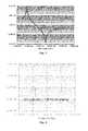
- FIG. 4is an admittance data diagram for a 32-MHz shear-mode resonator with straight-line folded tethers for stress isolation showing admittance data for the desired shear-mode resonance;
- FIG. 5is an admittance data diagram showing admittance data for the extraneous mode shown in FIG. 3 ;
- FIG. 6is a plan diagram of a quartz resonator with isolation tethers which have rounded corners and which the width of the tether is varied along its length for minimizing extraneous modes, in accordance with principles of the present invention
- FIG. 7 and FIG. 8are admittance simulations of 32-MHz fundamental mode resonators showing the extraneous modes below about 5 MHz with and without tethers with widths that vary along their length, respectively;
- FIG. 9is a plan diagram of a doubly clamped quartz resonator design with rounded corners for preventing cracking of the tethers during bonding and release, in accordance with principles of the present invention.
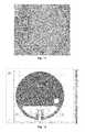
- FIG. 10is a diagram of a circular resonator in which FIG. 10A is a side view and FIG. 10B is a plan view of a circular SC-cut 75-MHz resonator with tethers to isolate the stress from the mounts from the active region, in accordance with principles of the present invention
- FIG. 11is a plan diagram of a fabricated VHF quartz resonator bonded to a substrate with conformally wrapped curved tethers producing a stress isolated resonator with a compact circular footprint, in accordance with principles of the present invention.
- FIG. 12 and FIG. 13are computer generated modal stress analyses of the fundamental mode using conformally wrapped curved tethers for stress isolation, high yield manufacturing (low cracking), and ultra-small overall footprint.
- FIG. 1is a plan diagram of a MEMs-based quartz resonator without tethers between bond pads and the resonator.
- a substrate 100has a quartz plate 104 bonded to it and a quartz resonator 102 is fabricated from the quartz plate 104 .
- Bond pads 106are used to bond the resonator 102 to corresponding pads on the substrate.
- the bond of the quartz plate 104 to the semiconductor substrate 100is typically produced using a Au/In eutectic bond which can be initially created at low bond temperatures ( ⁇ 150° C.).
- the metallizationcan then be interdiffused at a higher temperature to form a robust attachment that can withstand much higher temperature processing for vacuum packaging and die attachment processes.
- the Au/Inis deposited at wafer level. The typical geometry of this bonding area relative to the active region of the resonator is shown in FIG. 1 .
- the thermal expansion coefficient of quartzis 7.8 ⁇ 10 ⁇ 6 /° C. in the Z-direction and 14.3 ⁇ 10 ⁇ 6 /° C. perpendicular to the Z-direction while Si has a thermal expansion coefficient of 2.5 ⁇ 10 ⁇ 6 /° C.
- the bond padsthen produce a generally compressive stress on the quartz. This stress can propagate into the active region producing strain which changes the elastic constants, the dimensions, and the density. These changes then produce frequency shifts which vary as the temperature is changed resulting in apparent rotations of the f/T curves.
- the high stress in the metallic bond metalcan partially relax over time resulting in hysteresis in the f/T profiles.
- FIG. 2is a plan diagram of a resonator assembly 200 of a quartz resonator active region 202 , two mounts 201 and two corresponding isolation tethers 204 .
- Each isolation tether 204has three sections.
- the longitudinal axis of the assembly 200is represented by the x axis and the transverse axis of the assembly 200 is represented by the y axis. Elements closer to the origin are termed proximal and elements farther from the origin are termed distal.
- Respective mounts 201are coupled to corresponding first sections 206 by rounded inner and outer corners 208 .
- the first sections 206are coupled through a right angle to respective second sections 210 by corresponding rounded outer corners 212 and rounded inner corners 214 .
- the second sections 210are coupled through a right angle to respective third sections 216 by inner and outer rounded corners 218 .
- the third sections 216are coupled to the resonator active region 202 by rounded inner corners 219 .
- the respective isolation tethers 204form a straight line 220 between the inner corners 219 .
- rounded cornersreduce and/or minimize cracking of the tethers 204 during the bonding and release steps. With rounded corners as shown in FIG. 2 , this problem can be reduced and/or minimized to maintain high manufacturing yield. Also, the high stress leading to cracking is more critical on the inner corners than on the outer corners.
- Narrow tethersprovide a less stiff structure and therefore a higher degree of stress relief. Wider tethers are more stiff and therefore provide less stress relief through their length. Tethers that are as narrow as possible, while satisfying fabrication tolerance design rules, are preferred.
- FIG. 4is an exemplary admittance data diagram for a 32-MHz shear-mode resonator with straight-line folded tethers for stress isolation as illustrated in FIG. 2 showing admittance data for the desired shear-mode resonance.
- the measured values for the resonator equivalent circuit producing the admittance data diagram of FIG. 4are:
- FIG. 3is a stress diagram of a 1.6 MHz extraneous mode produced by the long straight tethers used for stress isolation, as illustrated in FIG. 2 .
- Straight folded spring segmentscan allow extraneous modes to develop which are electrically active and can compete with the main high Q shear mode, as described above.
- FIG. 3An example of this type of mode is shown in FIG. 3 .
- FIG. 5is an admittance data diagram showing admittance data for the extraneous mode shown in FIG. 3 .
- the measured values for the resonator equivalent circuit producing the admittance data diagram of FIG. 5are:
- FIG. 6is a plan diagram of a resonator assembly 600 including a quartz resonator active region 602 , mounts 601 and isolation tethers 604 .
- the longitudinal axis of the assembly 600is represented by the x axis and the transverse axis of the assembly 600 is represented by the y axis. Elements closer to the origin are termed proximal and elements farther from the origin are termed distal.
- the respective mounts 601are coupled to corresponding first sections 606 of the isolation tethers 604 by rounded inner and outer corners 608 .
- the respective first sectionsare coupled through a right angle to corresponding second sections 610 by rounded outer corners 612 and rounded inner corners 614 .
- the respective second sectionsare coupled through a right angle to corresponding third sections 616 by rounded inner and outer corners 618 .
- the respective third sections 616are coupled to the resonator active region 602 .
- the respective isolation tethers 604form a continuous curve, for example a semicircle, arc of an ellipse, or any similar curve, as illustrated in FIG. 6 , between the respective inner corners 618 of the second sections 610 .
- the width of the respective third sections 616 of the isolation tethers 604is, thus, varied along its length for minimizing the amplitude of extraneous modes.
- the width of the tether 604is varied along its length from a narrow section 630 to a wide section 632 .
- the curved tether design of FIG. 6(1) reduces cracking by reducing the stress near corners and (2) reduces the strength of extraneous flexural modes along the length of the tethers 604 .
- the relative piezoelectric current levels between the original extraneous mode and the modes for the new designare shown in the admittance plots of FIG. 7 and FIG. 8 , respectively.
- FIG. 7 and FIG. 8are admittance simulations of extraneous modes below about 5 MHz without and with tethers with widths that vary along their length, respectively.
- admittance valuesare normalized to 1 v.
- FIG. 7illustrates the admittance data related to the 1.6 MHz extraneous mode in the design of FIG. 2 .
- FIG. 7illustrates a pronounced resonance mode at 1.6 MHz.
- FIG. 8illustrates the admittance data related to the 1.6 MHz extraneous mode in the design of FIG. 6 .
- the quality factor (Q) of the resonance response in the design of FIG. 6is reduced 20 times and the admittance is reduced by 100 ⁇ , as noted in the figure.
- FIG. 9is a plan diagram of a resonator assembly 900 of a doubly clamped quartz resonator design with rounded corners for preventing cracking of the tethers during bonding and release.
- the doubly clamped design with rounded cornersalso reduces strain in the resonator from vibration.
- the longitudinal axis of the assembly 900is represented by the x axis and the transverse axis of the assembly 900 is represented by the y axis. Elements closer to the origin are termed proximal and elements farther from the origin are termed distal.
- the resonator assembly 900includes a resonator active region 902 fabricated on a mesa 903 and four mounts 901 .
- Four corresponding isolation tethers 904couple the respective mounts 901 to the resonator active region 902 .
- Two pairs of isolation tethers 904are fabricated, one pair proximal on the longitudinal axis of FIG. 9 and one pair distal on the longitudinal axis of FIG. 9 .
- the respective mounts 901are coupled to corresponding first sections 906 of the isolation tethers 904 by rounded inner and outer corners 908 .
- the respective first sections 906are coupled through a right angle to corresponding second sections 910 by rounded outer corners 912 and rounded inner corners 914 .
- Respective second sections 910are coupled to corresponding third sections 916 by rounded inner and outer corners 918 .
- the respective third sections 916are coupled to the resonator active region 902 by a rounded inner corner 919 .
- the respective isolation tethers 904 at the proximal longitudinal endform a continuous curve 920 between the respective inner corners 919 .
- the respective isolation tethers 904 at the distal longitudinal endform a continuous curve 920 between the respective inner corners 919 .
- the continuous curvemay be semicircular, an arc of a ellipse, or other similar continuous curve.
- the curved isolation tethers 904reduce or minimize stress between the mounts 901 and the resonator active region 902 , and reduce cracking during fabrication, improving yield.
- the continuous curve 620 formed by the isolation tethers 604 in FIG. 6runs between the inner corners 618 of the second sections 610 .
- the respective continuous curves 920 formed by the isolation tethers 904run between the inner corners 919 of the third sections 916 .
- the isolation tethers 904 of FIG. 9have a longer third section 916 compared to the third section 616 in FIG. 6 , and the third section 916 has a relatively constant width, compared to the third section 616 .
- the degree of curvature of the isolation tethersin general determines the level of stiffness of the structure and the amount of extraneous mode extinction.
- Thisis a trade-off. As the curvature is more prominent, the stiffness of the structure increases and the extraneous modes amplitude decreases, however, the stress in the resonator active region increases correspondingly. Therefore, the selection of the curvature of the isolation tethers is predicated on reducing extraneous modes while not compromising the resonator performance in terms of stress in the active region.
- FIG. 10is a diagram of a resonator assembly 1000 , in which FIG. 10A is a side view and FIG. 10B is a plan view of a circular SC-cut 75-MHz resonator assembly 1000 with isolation tethers 1004 to isolate the stress at the mounts 1001 from the resonator active region 1002 .
- the longitudinal axis of the assembly 1000is represented by the x axis and the transverse axis of the assembly 1000 is represented by the y axis. Elements closer to the origin are termed proximal and elements farther from the origin are termed distal.
- the assembly 1000is fabricated from quartz and may have a diameter of 950 ⁇ m and a thickness of 19.5 ⁇ m ( 1010 ).
- the mounts 1001may be 100 ⁇ m in the x-axis direction, and 200 ⁇ m in the y-axis direction of FIG. 10 , and are separated by a gap of 30 ⁇ m.
- the resonator in the active region 1002is fabricated on a mesa 1005 having a thickness of 22.0 ⁇ m ( 1008 ).
- the resonator active region 1002is elliptical having a major axis of 580 ⁇ m, and a minor axis of 560 ⁇ m.
- the mesa 1005may be fabricated to form a 25 ⁇ m margin around the resonator active region 1002 .
- a via 1012may have a diameter of 100 ⁇ m and may be fabricated in the assembly 1000 .
- the resonator assembly 1000 of FIG. 10includes curved isolation tethers 1004 which wrap around a circular or elliptical or similarly shaped resonator to conform to the shape of the resonator, termed conformally wrapped in this application, and maintain a small circular footprint for integration with other sensors.
- the shape of such isolation tethersis substantially circular, termed quasi-circular in this application.
- the respective mounts 1001 of the isolation tethers 1004are coupled through a right angle to corresponding first sections 1006 by rounded inner and outer corners 1008 .
- the respective first sections 1006are coupled to corresponding quasi-circular second sections 1010 by rounded inner and outer corners 1012 .
- the respective second sections 1010are substantially arcuate and substantially constant in width.
- the second sections 1010 of the curved isolation tethers 1004may have a transverse width of 50 ⁇ m.
- the respective second sections 1010are coupled to the resonator active region 1002 by a circular inner corner 1018 .
- Some embodimentsinclude two sections in the respective isolation tethers 1004 : one substantially straight section (e.g. 1006 ) and one substantially curved (e.g. 1010 ).
- a high fidelity plasma etchmay be used to form the 50- ⁇ m-wide tethers and gaps in VHF shear-mode resonators where the thickness of the quartz can be of comparable dimensions.
- the isolation tethers 904 at the proximal end and distal end, respectively, of the transverse axisform respective continuous curves between the curved inner corners of the third sections 916 .
- FIG. 11is a plan diagram of a fabricated VHF quartz resonator assembly 1000 as illustrated in FIG. 10 , in which the mounts 1001 are bonded in place to a substrate 1100 with conformally wrapped curved tethers 1004 producing a stress isolated resonator with a compact circular footprint
- VHF resonatorcan fabricated with stress isolation and with a total footprint of only about 1-mm in diameter.
- Other straight folded spring designssuch as those illustrated in FIG. 2 , FIG. 6 and FIG. 9 , can increase the overall length of the resonator.
- FIG. 12 and FIG. 13are computer simulated von Mises stress analyses for a resonator assembly 1000 using conformally wrapped curved tethers 1004 for stress isolation, high yield manufacturing (low cracking), and ultra-small overall footprint.
- FIG. 12shows stress in the range from 0 to 10 MPa, with dark regions representing areas of lower stress and lighter regions representing areas of higher stress. As illustrated in FIG. 12 , stress in the active region of the resonator 1002 is relatively low, while the higher stress is attenuated in the isolation tethers 1004 .
- FIG. 12shows stress in the range from 0 to 10 MPa, with dark regions representing areas of lower stress and lighter regions representing areas of higher stress. As illustrated in FIG. 12 , stress in the active region of the resonator 1002 is relatively low, while the higher stress is attenuated in the isolation tethers 1004 .
- FIG. 13shows stress in the range from 0 to 1 MPa. That is, a shade of gray in FIG. 12 represents a stress level 10 ⁇ the stress level represented by that same shade of gray in FIG. 13 . In FIG. 13 , dark regions represent lower stress and lighter regions represent higher stress. As illustrated in FIG. 13 , stress in the active region of the resonator 1002 is relatively low, while some stress is present in the region just beyond the isolation tethers 1004 . The isolation tethers 1004 have the highest amount of stress.
- most of the stressis attenuated in the isolation tethers, and the resulting stress at the center of the electrode is 40.3 kPa or less at an operating condition of 80° C.
- a satisfactory level of stress for quartz resonatorsmay be 100 kPa stress or less. This provides a very low stress level and mitigates ppm level changes in the frequency of the resonator.
Landscapes
- Physics & Mathematics (AREA)
- Acoustics & Sound (AREA)
- Engineering & Computer Science (AREA)
- Manufacturing & Machinery (AREA)
- Piezo-Electric Or Mechanical Vibrators, Or Delay Or Filter Circuits (AREA)
Abstract
Description
The present application claims priority from provisional application 61/976,944, filed Apr. 8, 2014, and titled “Tethers for Quartz Resonators” the disclosure of which is incorporated by reference herein.
This invention was made with Government support under Contract No. withheld/N66001--13--C--4020 Co--Integration of High--Aspect--Ratio Si Gyros & Quartz Clocks for Improved Inertial Performance. The Government has certain rights in the invention.
The present invention relates to mounting microelectro-mechanical system (MEMS) components on a substrate, and in particular to tethers for reducing stress on the MEMS component and increasing fabrication yield.
Because characteristics of nearly all electronic components vary with temperature, to maintain accuracy it is desirable for them to operate in an environment in which the temperature is kept substantially constant. Placing a controlled heater element near other components (resonators, gyroscopes, etc.) in a system or subsystem to maintain a substantially constant temperature is termed ovenization. An ovenization approach has been used for improving the performance of inertial MEMS devices using a frequency locking technique with two resonators with different f/T (frequency/temperature) characteristics. This technique has been shown to substantially improve the bias and turn-on to turn-on stability of gyroscopes. The accuracy of the ovenization technique is improved by minimizing thermal gradients and thermal time constants between the two resonators. Placing the components of the system or subsystem in a common housing minimizes thermal gradients. Placing a controlled heating element within the housing further aids in maintaining a substantially constant temperature further minimizing thermal gradients.
Mounting MEMS components on a substrate is a technique for encapsulating on a single chip a variety of different components providing different functionality. This may be done by bonding these components to a single semiconductor substrate. Some components, such as resonators and gyroscopes, are sensitive to strain during operation, and the presence of strain can make readings from that component inaccurate. Strain may be caused by stress induced during the bonding process to semiconductor substrates. This can also create breaks and cracks at sharp corners in quartz. In addition, strain may be caused by stress induced during operation by vibration, attitude changes, acceleration, and temperature gradients.
More specifically, for quartz resonators bonded to Si substrates, the differential thermal expansion between the quartz and the Si substrate can produce stress in the quartz which leads to strain. Strain in the quartz, in turn, changes the elastic constants, density and dimensions of the quartz plate. These changes can affect the frequency versus temperature characteristics of the quartz resonator. For commercial quartz resonators, the quartz is bonded with a compliant conductive epoxy within a ceramic package. The epoxy reduces the stress propagation into the quartz. However, for metallic solder bonding to Si substrates, other methods are needed to prevent the strain in the active region from modifying the expected f/T (frequency versus temperature) profiles.
For devices that require some form of stress isolation from the mounts for thermal stability, integrated tethers offer a solution. That is, to minimize strain during fabrication and operation, sensitive components may be mounted to the substrate using one or more tethers which can substantially dissipate strain before it can affect the component. High manufacturing yield for integrated tether designs is also critical.
One technique for minimizing stress, and thus undesirable strain, uses a folded spring tether design. However, a conventional folded spring design can suffer from low yield in the manufacturing process. In addition, some conventional tether designs can allow extraneous shearing modes to develop which can propagate in the plane of the resonator and create active electrical resonances at lower frequencies than the main thickness shear mode. In addition, some conventional folded spring designs can lead to extraneous in-plane modes that can interfere with the operation of the oscillator.
A tether design that can minimize transmission of stress from a substrate to a MEMS component, while reducing or minimizing inducing extraneous in-plane modes and increasing fabrication yields is desirable.
The inventors have discovered that using bonding temperatures above room temperature can create stress over a 3″ wafer stack consisting of a quartz handle wafer and a Si substrate such that quartz tethers can break at sharp corners near the bond sites. Typically, as many as 50% of the devices across a wafer can be affected. This is an experimental observation that is difficult to predict through simulations. The inventors have also discovered that by rounding the corners this cracking near high stress regions can be reduced.
They have also learned that straight folded tether designs can lead to extraneous active modes developing at lower frequencies than the usual in-plane shear mode. In some cases, these modes can have a reasonable high Q and can compete with the main mode within an oscillator circuit. By curving and varying the width of the tethers along their length, these extraneous modes can be suppressed.
The inventors have realized that unless the corners are rounded, folded spring tethers can crack during the bonding process due to differential expansion between the base wafer and the handle wafer on which the resonators are mounted. In addition, quasi-circular tethers can be used to eliminate extraneous in-plane modes. Finally, circular symmetric designs allow the integration of a quartz resonator with other larger circular symmetric devices such as gyros for miniaturization and tight environmental coupling. These tethers can be singly clamped or doubly clamped designs to minimize vibration sensitivity while maintaining low stress over temperature in the active regions. Unless the integrated tethers have rounded corners, are curved, or in some cases varied in width along their length, low yield and extraneous modes can result. In addition, for applications which require the smallest footprint possible, the use of tether designs that wrap conformally around the resonator allow compact integration and packaging.
In accordance with principles of the present invention a piezoelectric quartz shear-mode resonator includes plasma etched quartz tethers, each comprising a mount, for mounting the resonator to a semiconductor substrate for the purpose of isolating the thermally-induced stress from the mounts from the active resonating region wherein the quartz tethers have rounded corners.
Using a resonator design in accordance with principles of the present invention, quartz and Si gyro resonators can be integrated with a very small footprint that is no larger than a gyroscope itself. This produces a small and rigid package for e.g. air and ground vehicle navigation systems. By using doubly clamped rounded and curved tethers, the phase noise vibration sensitivity can also be reduced in high-g environments.
In one embodiment, the proposed quartz resonator is designed to be integrated on a Si substrate with rounded and curved, quasi-circular, or circularly symmetric integrated quartz tethers. By curving and widening the tethers along their length dimension, extraneous modes can be minimized or eliminated. Finally, by wrapping the tethers in a circular or quasi-circular fashion around the resonator, the overall footprint of the resonator can be reduced while minimizing high stress points which can crack the tethers during fabrication.
Quartz MEMS resonators can be integrated to semiconductor substrates using wafer-level processes in a known manner.FIG. 1 is a plan diagram of a MEMs-based quartz resonator without tethers between bond pads and the resonator. InFIG. 1 , asubstrate 100 has aquartz plate 104 bonded to it and aquartz resonator 102 is fabricated from thequartz plate 104.Bond pads 106 are used to bond theresonator 102 to corresponding pads on the substrate.
The bond of thequartz plate 104 to thesemiconductor substrate 100 is typically produced using a Au/In eutectic bond which can be initially created at low bond temperatures (<150° C.). The metallization can then be interdiffused at a higher temperature to form a robust attachment that can withstand much higher temperature processing for vacuum packaging and die attachment processes. The Au/In is deposited at wafer level. The typical geometry of this bonding area relative to the active region of the resonator is shown inFIG. 1 .
The thermal expansion coefficient of quartz is 7.8×10⁻⁶/° C. in the Z-direction and 14.3×10⁻⁶/° C. perpendicular to the Z-direction while Si has a thermal expansion coefficient of 2.5×10⁻⁶/° C. As the temperature of the resonator is increased the quartz tends to expand more than the Si to which it is mounted. The bond pads then produce a generally compressive stress on the quartz. This stress can propagate into the active region producing strain which changes the elastic constants, the dimensions, and the density. These changes then produce frequency shifts which vary as the temperature is changed resulting in apparent rotations of the f/T curves. Moreover, the high stress in the metallic bond metal can partially relax over time resulting in hysteresis in the f/T profiles. Computer simulation 3-D stress models have shown that the typical stress generated in the active regions for VHF-UHF resonator geometries similar to that shown inFIG. 1 can be 500 KPa to 1 MPa for a ΔT=80° C. These stress level can produce measureable changes in the frequency at the 10-100 part-per-million (ppm) level.
Several folded tether designs have been used in order to reduce the stress propagation from the mounts to the active regions. However, in many folded tether designs the tethers can break due to stress that develops during the heterogeneous bonding of the quartz resonators on quartz handle wafers to Si substrates and during subsequent release steps.
In general, rounded corners reduce and/or minimize cracking of thetethers 204 during the bonding and release steps. With rounded corners as shown inFIG. 2 , this problem can be reduced and/or minimized to maintain high manufacturing yield. Also, the high stress leading to cracking is more critical on the inner corners than on the outer corners.
Narrow tethers provide a less stiff structure and therefore a higher degree of stress relief. Wider tethers are more stiff and therefore provide less stress relief through their length. Tethers that are as narrow as possible, while satisfying fabrication tolerance design rules, are preferred.
- R1=12.4 Ω,
- C1=5.53×10⁻¹⁵F,
- L1=3.76×10⁻³H,
- C0=4.3×10⁻¹²F and
- Q=61 k
- R1=1289 Ω,
- C1=2.33×10⁻¹⁵F,
- L1=4.1 H,
- C0=3.65×10⁻¹²F and
- Q=33 k
The electrical admittance of this extraneous mode is compared to the fundamental shear mode inFIG. 4 andFIG. 5 .
The respective mounts601 are coupled to correspondingfirst sections 606 of the isolation tethers604 by rounded inner andouter corners 608. The respective first sections are coupled through a right angle to correspondingsecond sections 610 by roundedouter corners 612 and roundedinner corners 614. The respective second sections are coupled through a right angle to correspondingthird sections 616 by rounded inner andouter corners 618. The respectivethird sections 616 are coupled to the resonatoractive region 602. The respective isolation tethers604 form a continuous curve, for example a semicircle, arc of an ellipse, or any similar curve, as illustrated inFIG. 6 , between the respectiveinner corners 618 of thesecond sections 610. The width of the respectivethird sections 616 of the isolation tethers604 is, thus, varied along its length for minimizing the amplitude of extraneous modes.
In the curved tether design ofFIG. 6 the width of thetether 604 is varied along its length from anarrow section 630 to awide section 632. The curved tether design ofFIG. 6 : (1) reduces cracking by reducing the stress near corners and (2) reduces the strength of extraneous flexural modes along the length of thetethers 604. The relative piezoelectric current levels between the original extraneous mode and the modes for the new design are shown in the admittance plots ofFIG. 7 andFIG. 8 , respectively.
InFIG. 9 , theresonator assembly 900 includes a resonatoractive region 902 fabricated on amesa 903 and fourmounts 901. Four corresponding isolation tethers904 couple therespective mounts 901 to the resonatoractive region 902. Two pairs of isolation tethers904 are fabricated, one pair proximal on the longitudinal axis ofFIG. 9 and one pair distal on the longitudinal axis ofFIG. 9 . The respective mounts901 are coupled to correspondingfirst sections 906 of the isolation tethers904 by rounded inner andouter corners 908. The respectivefirst sections 906 are coupled through a right angle to correspondingsecond sections 910 by roundedouter corners 912 and roundedinner corners 914. Respectivesecond sections 910 are coupled to correspondingthird sections 916 by rounded inner andouter corners 918. The respectivethird sections 916 are coupled to the resonatoractive region 902 by a roundedinner corner 919. The respective isolation tethers904 at the proximal longitudinal end form acontinuous curve 920 between the respectiveinner corners 919. Similarly, the respective isolation tethers904 at the distal longitudinal end form acontinuous curve 920 between the respectiveinner corners 919. The continuous curve may be semicircular, an arc of a ellipse, or other similar continuous curve. The curved isolation tethers904 reduce or minimize stress between themounts 901 and the resonatoractive region 902, and reduce cracking during fabrication, improving yield.
Comparing theresonator assembly 600 inFIG. 6 to that of900 inFIG. 9 , thecontinuous curve 620 formed by the isolation tethers604 inFIG. 6 runs between theinner corners 618 of thesecond sections 610. InFIG. 9 , the respectivecontinuous curves 920 formed by the isolation tethers904 run between theinner corners 919 of thethird sections 916. In addition, the isolation tethers904 ofFIG. 9 have a longerthird section 916 compared to thethird section 616 inFIG. 6 , and thethird section 916 has a relatively constant width, compared to thethird section 616. The degree of curvature of the isolation tethers in general determines the level of stiffness of the structure and the amount of extraneous mode extinction. One skilled in the art understands that this is a trade-off. As the curvature is more prominent, the stiffness of the structure increases and the extraneous modes amplitude decreases, however, the stress in the resonator active region increases correspondingly. Therefore, the selection of the curvature of the isolation tethers is predicated on reducing extraneous modes while not compromising the resonator performance in terms of stress in the active region.
Theassembly 1000 is fabricated from quartz and may have a diameter of 950 μm and a thickness of 19.5 μm (1010). Themounts 1001 may be 100 μm in the x-axis direction, and 200 μm in the y-axis direction ofFIG. 10 , and are separated by a gap of 30 μm. The resonator in theactive region 1002 is fabricated on amesa 1005 having a thickness of 22.0 μm (1008). The resonatoractive region 1002 is elliptical having a major axis of 580 μm, and a minor axis of 560 μm. Themesa 1005 may be fabricated to form a 25 μm margin around the resonatoractive region 1002. A via1012 may have a diameter of 100 μm and may be fabricated in theassembly 1000.
Theresonator assembly 1000 ofFIG. 10 includescurved isolation tethers 1004 which wrap around a circular or elliptical or similarly shaped resonator to conform to the shape of the resonator, termed conformally wrapped in this application, and maintain a small circular footprint for integration with other sensors. The shape of such isolation tethers is substantially circular, termed quasi-circular in this application. Therespective mounts 1001 of the isolation tethers1004 are coupled through a right angle to correspondingfirst sections 1006 by rounded inner andouter corners 1008. The respectivefirst sections 1006 are coupled to corresponding quasi-circularsecond sections 1010 by rounded inner andouter corners 1012. The respectivesecond sections 1010 are substantially arcuate and substantially constant in width. In some embodiments, thesecond sections 1010 of thecurved isolation tethers 1004 may have a transverse width of 50 μm. The respectivesecond sections 1010 are coupled to the resonatoractive region 1002 by a circularinner corner 1018. Some embodiments include two sections in the respective isolation tethers1004: one substantially straight section (e.g.1006) and one substantially curved (e.g.1010). A high fidelity plasma etch may be used to form the 50-μm-wide tethers and gaps in VHF shear-mode resonators where the thickness of the quartz can be of comparable dimensions.
ComparingFIG. 10B toFIG. 9 , inFIG. 9 , the isolation tethers904 at the proximal end and distal end, respectively, of the transverse axis form respective continuous curves between the curved inner corners of thethird sections 916.
An advantage of this design is that a VHF resonator can fabricated with stress isolation and with a total footprint of only about 1-mm in diameter. Other straight folded spring designs, such as those illustrated inFIG. 2 ,FIG. 6 andFIG. 9 , can increase the overall length of the resonator.
The stress isolation for theresonator assembly 1000 ofFIG. 10 is shown inFIG. 12 andFIG. 13 for a room temperature (RT) to 80° C. temperature change ΔT.FIG. 12 andFIG. 13 are computer simulated von Mises stress analyses for aresonator assembly 1000 using conformally wrappedcurved tethers 1004 for stress isolation, high yield manufacturing (low cracking), and ultra-small overall footprint.FIG. 12 shows stress in the range from 0 to 10 MPa, with dark regions representing areas of lower stress and lighter regions representing areas of higher stress. As illustrated inFIG. 12 , stress in the active region of theresonator 1002 is relatively low, while the higher stress is attenuated in the isolation tethers1004.FIG. 13 shows stress in the range from 0 to 1 MPa. That is, a shade of gray inFIG. 12 represents a stress level 10× the stress level represented by that same shade of gray inFIG. 13 . InFIG. 13 , dark regions represent lower stress and lighter regions represent higher stress. As illustrated inFIG. 13 , stress in the active region of theresonator 1002 is relatively low, while some stress is present in the region just beyond the isolation tethers1004. The isolation tethers1004 have the highest amount of stress.
As illustrated inFIG. 12 andFIG. 13 , most of the stress is attenuated in the isolation tethers, and the resulting stress at the center of the electrode is 40.3 kPa or less at an operating condition of 80° C. A satisfactory level of stress for quartz resonators may be 100 kPa stress or less. This provides a very low stress level and mitigates ppm level changes in the frequency of the resonator.
Claims (12)
1. A piezoelectric quartz shear-mode resonator comprising quartz isolation tethers, each comprising a mount for mounting to a semiconductor substrate, wherein the quartz tethers each have at least one rounded corner.
2. The quartz shear-mode resonator ofclaim 1 wherein:
the respective mounts are coupled to corresponding first sections of the isolation tethers by rounded outer corners and inner corners;
the respective first sections are coupled through a right angle to corresponding second sections by a rounded outer corner and a rounded inner corner;
the respective second sections are coupled through a right angle to corresponding third sections by rounded outer corners and inner corners; and
the respective third sections are coupled to the resonator by an rounded inner corner; wherein
the respective isolation tethers form a straight line between the inner corners of the third sections.
3. The quartz shear-mode resonator ofclaim 1 wherein:
the respective mounts are coupled to corresponding first sections by rounded outer corners and inner corners;
the respective first sections are coupled through a right angle to corresponding second sections by a rounded outer corner and a rounded inner corner; and
the respective second sections are coupled through a right angle to corresponding third sections by rounded outer corners and inner corners; and
the respective third sections are coupled to the resonator by a rounded inner corner; wherein
the respective isolation tethers form a continuous curve between the rounded outer and inner corners of the second sections.
4. The quartz shear-mode resonator ofclaim 1 wherein:
the respective mounts are coupled to corresponding first sections by rounded outer corners and inner corners;
the respective first sections are coupled through a right angle to corresponding second sections by a rounded outer corner and a rounded inner corner;
the respective second sections are coupled through right angles to corresponding third sections by rounded outer and inner corners;
the respective third sections are coupled to the resonator by a rounded inner corner; wherein
the respective isolation tethers form a continuous curve between the inner corners of the third section.
5. The quartz shear-mode resonator ofclaim 1 wherein:
the resonator is round or elliptical;
the isolation tethers are conformally wrapped around the resonator, wherein:
the respective mounts are coupled through a right angle to corresponding first sections of the tethers by rounded outer corners and inner corners;
the respective first sections are coupled through substantially right angles to corresponding quasi-circular second sections by rounded outer corners and inner corners; and
the respective second sections are coupled to the resonator by corresponding rounded inner corners; wherein
the respective isolation tethers form a substantially straight line between the inner corners of the third section.
6. The quartz shear-mode resonator ofclaim 1 wherein the quartz isolation tethers are plasma etched.
7. The quartz shear-mode resonator ofclaim 1 wherein the quartz isolation tethers are rounded or quasi-circular.
8. The quartz shear-mode resonator ofclaim 1 wherein the lateral width of the quartz isolation tethers is varied along its length.
9. The quartz shear-mode resonator ofclaim 1 wherein two sets of rounded or quasi-circular isolation tethers are attached to opposite sides of the resonator to minimize vibrational-induced strain in the resonator.
10. The quartz shear-mode resonator ofclaim 1 wherein the resonator is bonded to the semiconductor substrate with a metallic solder in the mount regions.
11. The quartz shear-mode resonator ofclaim 1 , wherein the quartz shear-mode resonator operates with its fundamental mode in the VHF or UHF ranges.
12. The quartz shear-mode resonator ofclaim 1 wherein the quartz is composed of AT or SC-cut material.
Priority Applications (1)
| Application Number | Priority Date | Filing Date | Title |
|---|---|---|---|
| US14/680,902US9991863B1 (en) | 2014-04-08 | 2015-04-07 | Rounded and curved integrated tethers for quartz resonators |
Applications Claiming Priority (2)
| Application Number | Priority Date | Filing Date | Title |
|---|---|---|---|
| US201461976944P | 2014-04-08 | 2014-04-08 | |
| US14/680,902US9991863B1 (en) | 2014-04-08 | 2015-04-07 | Rounded and curved integrated tethers for quartz resonators |
Publications (1)
| Publication Number | Publication Date |
|---|---|
| US9991863B1true US9991863B1 (en) | 2018-06-05 |
Family
ID=62235590
Family Applications (1)
| Application Number | Title | Priority Date | Filing Date |
|---|---|---|---|
| US14/680,902Active2036-09-10US9991863B1 (en) | 2014-04-08 | 2015-04-07 | Rounded and curved integrated tethers for quartz resonators |
Country Status (1)
| Country | Link |
|---|---|
| US (1) | US9991863B1 (en) |
Cited By (9)
| Publication number | Priority date | Publication date | Assignee | Title |
|---|---|---|---|---|
| US20190250198A1 (en)* | 2018-02-09 | 2019-08-15 | Hrl Laboratories, Llc | Dual Magnetic and Electric Field Quartz Sensor |
| US10819276B1 (en) | 2018-05-31 | 2020-10-27 | Hrl Laboratories, Llc | Broadband integrated RF magnetic antenna |
| US10892931B2 (en)* | 2016-08-31 | 2021-01-12 | Huawei Technologies Duesseldorf Gmbh | Filtered multi-carrier communications |
| US11101786B1 (en)* | 2017-06-20 | 2021-08-24 | Hrl Laboratories, Llc | HF-VHF quartz MEMS resonator |
| US11239823B1 (en) | 2017-06-16 | 2022-02-01 | Hrl Laboratories, Llc | Quartz MEMS piezoelectric resonator for chipscale RF antennae |
| US11563420B1 (en) | 2019-03-29 | 2023-01-24 | Hrl Laboratories, Llc | Femto-tesla MEMS RF antenna with integrated flux concentrator |
| US11626856B2 (en) | 2019-10-30 | 2023-04-11 | X-Celeprint Limited | Non-linear tethers for suspended devices |
| US11637540B2 (en)* | 2019-10-30 | 2023-04-25 | X-Celeprint Limited | Non-linear tethers for suspended devices |
| US11988727B1 (en) | 2019-07-31 | 2024-05-21 | Hrl Laboratories, Llc | Magnetostrictive MEMS magnetic gradiometer |
Citations (219)
| Publication number | Priority date | Publication date | Assignee | Title |
|---|---|---|---|---|
| US392650A (en) | 1888-11-13 | watrous | ||
| US2487165A (en) | 1946-10-10 | 1949-11-08 | August E Miller | Crystal electrode |
| US3390287A (en) | 1964-12-10 | 1968-06-25 | Kistler Instrumente Ag | Piezo-electric building units |
| US3766616A (en) | 1972-03-22 | 1973-10-23 | Statek Corp | Microresonator packaging and tuning |
| JPS5791017A (en) | 1980-11-27 | 1982-06-07 | Seiko Instr & Electronics Ltd | Gt-cut quartz oscillator |
| US4364016A (en) | 1980-11-03 | 1982-12-14 | Sperry Corporation | Method for post fabrication frequency trimming of surface acoustic wave devices |
| WO1984000082A1 (en) | 1982-06-14 | 1984-01-05 | Gte Prod Corp | Trimming of piezoelectric components |
| US4426769A (en) | 1981-08-14 | 1984-01-24 | Amp Incorporated | Moisture getter for integrated circuit packages |
| US4442574A (en) | 1982-07-26 | 1984-04-17 | General Electric Company | Frequency trimming of saw resonators |
| US4447753A (en) | 1981-03-25 | 1984-05-08 | Seiko Instruments & Electronics Ltd. | Miniature GT-cut quartz resonator |
| US4618262A (en) | 1984-04-13 | 1986-10-21 | Applied Materials, Inc. | Laser interferometer system and method for monitoring and controlling IC processing |
| JPH01129517A (en) | 1987-11-13 | 1989-05-22 | Fujitsu Ltd | Manufacture of surface wave resonance element |
| US4870313A (en) | 1985-04-11 | 1989-09-26 | Toyo Communication Equipment Co., Ltd. | Piezoelectric resonators for overtone oscillations |
| US4898031A (en) | 1987-07-24 | 1990-02-06 | Yazaki Corporation | Vibrational angular velocity sensor |
| US4944836A (en) | 1985-10-28 | 1990-07-31 | International Business Machines Corporation | Chem-mech polishing method for producing coplanar metal/insulator films on a substrate |
| EP0461761A1 (en) | 1990-05-18 | 1991-12-18 | British Aerospace Public Limited Company | Inertial sensors |
| JPH04322507A (en) | 1991-04-22 | 1992-11-12 | Matsushita Electric Ind Co Ltd | How to process crystal resonators |
| EP0531985A1 (en) | 1991-09-12 | 1993-03-17 | Matsushita Electric Industrial Co., Ltd. | Electro-acoustic hybrid integrated circuit and manufacturing method thereof |
| US5203208A (en) | 1991-04-29 | 1993-04-20 | The Charles Stark Draper Laboratory | Symmetrical micromechanical gyroscope |
| JPH05286142A (en) | 1992-04-13 | 1993-11-02 | Fujitsu Ltd | Inkjet head and manufacturing method thereof |
| US5260596A (en) | 1991-04-08 | 1993-11-09 | Motorola, Inc. | Monolithic circuit with integrated bulk structure resonator |
| JPH06232678A (en) | 1993-01-29 | 1994-08-19 | Hitachi Ltd | Surface acoustic wave resonator and method for manufacturing the same |
| JPH06318533A (en) | 1993-02-03 | 1994-11-15 | Tama Electric Co Ltd | Electronic component |
| US5421312A (en) | 1990-11-03 | 1995-06-06 | Dawson Royalties Limited | Electrical circuit |
| US5480747A (en) | 1994-11-21 | 1996-01-02 | Sematech, Inc. | Attenuated phase shifting mask with buried absorbers |
| DE4442033A1 (en) | 1994-11-25 | 1996-05-30 | Bosch Gmbh Robert | Yaw rate sensor |
| US5530408A (en) | 1995-05-25 | 1996-06-25 | The United States Of America As Represented By The Secretary Of The Army | Method of making an oven controlled crystal oscillator the frequency of which remains ultrastable under temperature variations |
| US5552016A (en) | 1993-04-28 | 1996-09-03 | Applied Materials, Inc. | Method and apparatus for etchback endpoint detection |
| US5578976A (en) | 1995-06-22 | 1996-11-26 | Rockwell International Corporation | Micro electromechanical RF switch |
| WO1996038710A1 (en) | 1995-05-31 | 1996-12-05 | Litef Gmbh | Micromechanical rotation speed sensor |
| JPH08330878A (en) | 1995-06-02 | 1996-12-13 | Matsushita Electric Ind Co Ltd | Oscillator manufacturing method |
| US5589724A (en) | 1993-01-25 | 1996-12-31 | Matsushita Electric Industrial Co., Ltd. | Piezoelectric device and a package |
| US5605490A (en) | 1994-09-26 | 1997-02-25 | The United States Of America As Represented By The Secretary Of The Army | Method of polishing langasite |
| US5644139A (en) | 1995-03-02 | 1997-07-01 | Allen; Ross R. | Navigation technique for detecting movement of navigation sensors relative to an object |
| US5646346A (en) | 1994-11-10 | 1997-07-08 | Okada; Kazuhiro | Multi-axial angular velocity sensor |
| US5648849A (en) | 1994-04-05 | 1997-07-15 | Sofie | Method of and device for in situ real time quantification of the morphology and thickness of a localized area of a surface layer of a thin layer structure during treatment of the latter |
| US5658418A (en) | 1995-03-31 | 1997-08-19 | International Business Machines Corporation | Apparatus for monitoring the dry etching of a dielectric film to a given thickness in an integrated circuit |
| US5665915A (en) | 1992-03-25 | 1997-09-09 | Fuji Electric Co., Ltd. | Semiconductor capacitive acceleration sensor |
| US5668057A (en) | 1991-03-13 | 1997-09-16 | Matsushita Electric Industrial Co., Ltd. | Methods of manufacture for electronic components having high-frequency elements |
| US5666706A (en) | 1993-06-10 | 1997-09-16 | Matsushita Electric Industrial Co., Ltd. | Method of manufacturing a piezoelectric acoustic wave device |
| JPH09247025A (en) | 1996-03-11 | 1997-09-19 | Murata Mfg Co Ltd | Antenna system |
| US5728936A (en) | 1995-08-16 | 1998-03-17 | Robert Bosch Gmbh | Rotary speed sensor |
| WO1998015799A1 (en) | 1996-10-07 | 1998-04-16 | HAHN-SCHICKARD-GESELLSCHAFT FÜR ANGEWANDTE FORSCHUNG E.V. Wilhelm-Schickard-Strasse 10 | Rotation rate sensor with uncoupled mutually perpendicular primary and secondary oscillations |
| US5783749A (en) | 1995-12-07 | 1998-07-21 | Electronics And Telecommunications Research Institute | Vibrating disk type micro-gyroscope |
| DE19719601A1 (en) | 1997-05-09 | 1998-11-12 | Bosch Gmbh Robert | Acceleration sensor with spring-mounted seismic mass |
| US5894090A (en) | 1996-05-31 | 1999-04-13 | California Institute Of Technology | Silicon bulk micromachined, symmetric, degenerate vibratorygyroscope, accelerometer and sensor and method for using the same |
| US5905202A (en) | 1995-09-01 | 1999-05-18 | Hughes Electronics Corporation | Tunneling rotation sensor |
| US5920012A (en) | 1998-06-16 | 1999-07-06 | Boeing North American | Micromechanical inertial sensor |
| US5928532A (en) | 1996-11-11 | 1999-07-27 | Tokyo Electron Limited | Method of detecting end point of plasma processing and apparatus for the same |
| US5942445A (en) | 1996-03-25 | 1999-08-24 | Shin-Etsu Handotai Co., Ltd. | Method of manufacturing semiconductor wafers |
| US5981392A (en) | 1996-03-28 | 1999-11-09 | Shin-Etsu Handotai Co., Ltd. | Method of manufacturing semiconductor monocrystalline mirror-surface wafers which includes a gas phase etching process, and semiconductor monocrystalline mirror-surface wafers manufactured by the method |
| US6009751A (en) | 1998-10-27 | 2000-01-04 | Ljung; Bo Hans Gunnar | Coriolis gyro sensor |
| EP0971208A2 (en) | 1998-07-10 | 2000-01-12 | Murata Manufacturing Co., Ltd. | Angular velocity sensor |
| US6044705A (en) | 1993-10-18 | 2000-04-04 | Xros, Inc. | Micromachined members coupled for relative rotation by torsion bars |
| US6049702A (en) | 1997-12-04 | 2000-04-11 | Rockwell Science Center, Llc | Integrated passive transceiver section |
| US6081334A (en) | 1998-04-17 | 2000-06-27 | Applied Materials, Inc | Endpoint detection for semiconductor processes |
| US6089088A (en) | 1997-11-07 | 2000-07-18 | Commissariat A L'energie Atomique | Vibrating microgyrometer |
| US6094985A (en) | 1996-11-22 | 2000-08-01 | Siemens Aktiengesellschaft | Rotation rate sensor |
| US6114801A (en) | 1997-04-14 | 2000-09-05 | Toyo Communication Equipment Co., Ltd. | At-cut crystal resonator |
| US6145380A (en) | 1997-12-18 | 2000-11-14 | Alliedsignal | Silicon micro-machined accelerometer using integrated electrical and mechanical packaging |
| WO2000068640A2 (en) | 1999-04-21 | 2000-11-16 | The Regents Of The University Of California | Micro-machined angle-measuring gyroscope |
| US6151964A (en) | 1998-05-25 | 2000-11-28 | Citizen Watch Co., Ltd. | Angular velocity sensing device |
| EP1055908A1 (en) | 1999-05-27 | 2000-11-29 | Delphi Technologies, Inc. | Angular rate sensor |
| US6155115A (en) | 1991-01-02 | 2000-12-05 | Ljung; Per | Vibratory angular rate sensor |
| US6164134A (en) | 1999-01-29 | 2000-12-26 | Hughes Electronics Corporation | Balanced vibratory gyroscope and amplitude control for same |
| US6182352B1 (en) | 1997-06-02 | 2001-02-06 | Avery Dennison Corporation | Method of manufacturing an EAS marker |
| US6196059B1 (en) | 1997-08-11 | 2001-03-06 | Fraunhofer Gesellschaft Zur Forderung Der Angewandten Forschung E.V. | Piezoelectric resonator, process for the fabrication thereof including its use as a sensor element for the determination of the concentration of a substance contained in a liquid and/or for the determination of the physical properties of the liquid |
| US6204737B1 (en) | 1998-06-02 | 2001-03-20 | Nokia Mobile Phones, Ltd | Piezoelectric resonator structures with a bending element performing a voltage controlled switching function |
| US6207008B1 (en) | 1997-12-15 | 2001-03-27 | Ricoh Company, Ltd. | Dry etching endpoint detection system |
| US6236145B1 (en) | 2000-02-29 | 2001-05-22 | Cts Corporation | High thermal resistivity crystal resonator support structure and oscillator package |
| WO2001044823A1 (en) | 1999-12-16 | 2001-06-21 | Robert Bosch Gmbh | Micromechanical spring structure, especially for a rotational speed sensor |
| US6250157B1 (en) | 1998-06-22 | 2001-06-26 | Aisin Seiki Kabushiki Kaisha | Angular rate sensor |
| US6263552B1 (en) | 1995-12-28 | 2001-07-24 | Ngk Insulators, Ltd. | Method of producing piezoelectric/electrostrictive film-type element |
| US6282958B1 (en) | 1998-08-11 | 2001-09-04 | Bae Systems Plc | Angular rate sensor |
| US6289733B1 (en) | 1999-05-12 | 2001-09-18 | Hughes Electronics Corporation | Planar vibratory gyroscopes |
| US6297064B1 (en) | 1998-02-03 | 2001-10-02 | Tokyo Electron Yamanashi Limited | End point detecting method for semiconductor plasma processing |
| WO2001074708A2 (en) | 2000-04-05 | 2001-10-11 | Interuniversitair Microelektronica Centrum (Imec) | Method for depositing polycrystalline sige suitable for micromachining and devices obtained thereof |
| KR20010110428A (en) | 1999-02-01 | 2001-12-13 | 비르 에이/에스 | A surface plasmon resonance sensor |
| WO2002012873A2 (en) | 2000-08-08 | 2002-02-14 | Smithkline Beecham P.L.C. | Quartz crystal microbalance |
| US6367786B1 (en) | 1999-06-07 | 2002-04-09 | California Institute Of Technology | Micromachined double resonator |
| US6367326B1 (en) | 1996-07-10 | 2002-04-09 | Wacoh Corporation | Angular velocity sensor |
| US20020066317A1 (en) | 2000-12-06 | 2002-06-06 | Gang Lin | Micro yaw rate sensors |
| US20020072246A1 (en) | 2000-12-11 | 2002-06-13 | Samsung Electronics Co., Ltd. | Method of forming a spin-on-glass insulation layer |
| US20020074947A1 (en) | 2000-09-01 | 2002-06-20 | Takeo Tsukamoto | Electron-emitting device, electron-emitting apparatus, image display apparatus, and light-emitting apparatus |
| US6413682B1 (en) | 1999-05-21 | 2002-07-02 | Shin-Etsu Chemical Co., Ltd. | Synthetic quartz glass substrate for photomask and making method |
| US6417925B1 (en) | 1999-08-26 | 2002-07-09 | Fuji Photo Film Co., Ltd. | Surface plasmon sensor for analyzing liquid sample or humid atmosphere |
| US6424418B2 (en) | 1998-05-29 | 2002-07-23 | Canon Kabushiki Kaisha | Surface plasmon resonance sensor apparatus using surface emitting laser |
| US6426296B1 (en) | 2000-09-08 | 2002-07-30 | The United States Of America As Represented By The Administrator Of The National Aeronautics And Space Administration | Method and apparatus for obtaining a precision thickness in semiconductor and other wafers |
| US6429652B1 (en) | 1999-06-21 | 2002-08-06 | Georgia Tech Research Corporation | System and method of providing a resonant micro-compass |
| US20020107658A1 (en) | 1999-09-20 | 2002-08-08 | Mccall Hiram | Processing method for motion measurement |
| US6432824B2 (en) | 2000-02-25 | 2002-08-13 | Speedfam Co., Ltd. | Method for manufacturing a semiconductor wafer |
| US6481284B2 (en) | 1997-09-02 | 2002-11-19 | Analog Devices, Inc. | Micromachined devices with anti-levitation devices |
| US6492195B2 (en) | 1999-12-24 | 2002-12-10 | Hitachi, Ltd. | Method of thinning a semiconductor substrate using a perforated support substrate |
| US20020185611A1 (en) | 2001-06-04 | 2002-12-12 | The Regents Of The University Of California | Combined advanced finishing and UV laser conditioning process for producing damage resistant optics |
| US20030003608A1 (en) | 2001-03-21 | 2003-01-02 | Tsunetoshi Arikado | Semiconductor wafer with ID mark, equipment for and method of manufacturing semiconductor device from them |
| US20030010123A1 (en) | 2000-01-13 | 2003-01-16 | Malvern Alan R | Accelerometer |
| US6513380B2 (en) | 2001-06-19 | 2003-02-04 | Microsensors, Inc. | MEMS sensor with single central anchor and motion-limiting connection geometry |
| US6515278B2 (en) | 1999-08-05 | 2003-02-04 | Microvision, Inc. | Frequency tunable resonant scanner and method of making |
| US6514767B1 (en) | 1999-10-06 | 2003-02-04 | Surromed, Inc. | Surface enhanced spectroscopy-active composite nanoparticles |
| US20030029238A1 (en) | 2001-08-10 | 2003-02-13 | The Boeing Company | Isolated resonator gyroscope |
| US6584845B1 (en) | 1999-02-10 | 2003-07-01 | California Institute Of Technology | Inertial sensor and method of use |
| US6614529B1 (en) | 1992-12-28 | 2003-09-02 | Applied Materials, Inc. | In-situ real-time monitoring technique and apparatus for endpoint detection of thin films during chemical/mechanical polishing planarization |
| US6621158B2 (en) | 1995-06-06 | 2003-09-16 | Analog Devices, Inc. | Package for sealing an integrated circuit die |
| US6628177B2 (en) | 2000-08-24 | 2003-09-30 | The Regents Of The University Of Michigan | Micromechanical resonator device and micromechanical device utilizing same |
| US6627067B1 (en) | 1999-06-22 | 2003-09-30 | President And Fellows Of Harvard College | Molecular and atomic scale evaluation of biopolymers |
| US20030196490A1 (en) | 2002-04-17 | 2003-10-23 | Donato Cardarelli | MEMS-integrated inertial measurement units on a common substrate |
| US20030205948A1 (en) | 2002-05-03 | 2003-11-06 | Asia Pacific Microsystems, Inc. | Film bulk acoustic device with integrated tunable and trimmable device |
| JP2003318685A (en) | 2002-04-22 | 2003-11-07 | Herutsu Kk | Manufacturing method of quartz resonator |
| US6686807B1 (en) | 1999-11-02 | 2004-02-03 | Eta Sa Fabriques D'ebauches | Time base comprising an integrated micromechanical ring resonator |
| US6710681B2 (en) | 2001-07-13 | 2004-03-23 | Agilent Technologies, Inc. | Thin film bulk acoustic resonator (FBAR) and inductor on a monolithic substrate and method of fabricating the same |
| US20040055381A1 (en) | 2002-08-12 | 2004-03-25 | Shcheglov Kirill V. | Integral resonator gyroscope |
| US20040055380A1 (en) | 2002-08-12 | 2004-03-25 | Shcheglov Kirill V. | Isolated planar gyroscope with internal radial sensing and actuation |
| US6713938B2 (en) | 1999-01-14 | 2004-03-30 | The Regents Of The University Of Michigan | Method and apparatus for filtering signals utilizing a vibrating micromechanical resonator |
| US6715352B2 (en) | 2001-06-26 | 2004-04-06 | Microsensors, Inc. | Method of designing a flexure system for tuning the modal response of a decoupled micromachined gyroscope and a gyroscoped designed according to the method |
| US20040065864A1 (en) | 2000-12-20 | 2004-04-08 | Kristina Vogt | Acidic polishing slurry for the chemical-mechanical polishing of SiO2 isolation layers |
| US6744335B2 (en) | 2000-02-16 | 2004-06-01 | Nokia Mobile Phones Ltd. | Micromechanical tunable capacitor and an integrated tunable resonator |
| US6750728B2 (en) | 2002-03-28 | 2004-06-15 | Humo Laboratory, Ltd. | Quartz oscillator and method for manufacturing the same |
| US6756304B1 (en) | 1999-07-30 | 2004-06-29 | Thales Avionics S.A. | Method for producing via-connections in a substrate and substrate equipped with same |
| US6768396B2 (en) | 1999-12-22 | 2004-07-27 | Koninklijke Philips Electronics N.V. | Filter arrangement |
| US6796179B2 (en) | 2002-05-17 | 2004-09-28 | California Institute Of Technology | Split-resonator integrated-post MEMS gyroscope |
| US20040189311A1 (en) | 2002-12-26 | 2004-09-30 | Glezer Eli N. | Assay cartridges and methods of using the same |
| US6806557B2 (en) | 2002-09-30 | 2004-10-19 | Motorola, Inc. | Hermetically sealed microdevices having a single crystalline silicon getter for maintaining vacuum |
| US20040211052A1 (en) | 2002-04-30 | 2004-10-28 | Kubena Randall L. | Quartz-based nanoresonators and method of fabricating same |
| US6815228B2 (en) | 2000-06-20 | 2004-11-09 | Hitachi, Ltd. | Film thickness measuring method of member to be processed using emission spectroscopy and processing method of the member using the measuring method |
| US20050024165A1 (en) | 2003-07-31 | 2005-02-03 | Wan-Thai Hsu | Apparatus comprising a micromechanical resonator |
| US20050034822A1 (en) | 2003-04-22 | 2005-02-17 | Samsung Electronics Co., Ltd. | Method for fabricating cantilevered type film bulk acoustic resonator and film bulk acoustic resonator fabricated by the same |
| US6862398B2 (en) | 2001-03-30 | 2005-03-01 | Texas Instruments Incorporated | System for directed molecular interaction in surface plasmon resonance analysis |
| US20050056917A1 (en) | 2003-09-15 | 2005-03-17 | Kwon Jong Oh | Wafer level package type FBAR device and manufacturing method thereof |
| US20050062368A1 (en) | 2003-08-19 | 2005-03-24 | Seiko Epson Corporation | Tuning-fork type piezo-oscillator piece and mounting method thereof |
| US6883374B2 (en) | 2001-09-14 | 2005-04-26 | Bae Systems Plc | Vibratory gyroscopic rate sensor |
| US20050093659A1 (en) | 2003-10-30 | 2005-05-05 | Larson John D.Iii | Film acoustically-coupled transformer with increased common mode rejection |
| US6909221B2 (en) | 2002-08-01 | 2005-06-21 | Georgia Tech Research Corporation | Piezoelectric on semiconductor-on-insulator microelectromechanical resonators |
| US6915215B2 (en) | 2002-06-25 | 2005-07-05 | The Boeing Company | Integrated low power digital gyro control electronics |
| JP2005180921A (en) | 2002-04-03 | 2005-07-07 | Japan Science & Technology Agency | Biosensor chip surface carrying polyethylene glycol modified nanoparticles |
| US20050156309A1 (en) | 1999-03-19 | 2005-07-21 | Tetsuo Fujii | Semiconductor sensor |
| US20050172714A1 (en) | 2002-08-12 | 2005-08-11 | California Institute Of Technology | Isolated planar mesogyroscope |
| US6933164B2 (en) | 2001-08-30 | 2005-08-23 | Hrl Laboratories, Llc | Method of fabrication of a micro-channel based integrated sensor for chemical and biological materials |
| US6943484B2 (en) | 2001-12-06 | 2005-09-13 | University Of Pittsburgh | Tunable piezoelectric micro-mechanical resonator |
| US6954020B2 (en) | 2001-06-11 | 2005-10-11 | Intel Corporation | Apparatus for adjusting the resonance frequency of a microelectromechanical (MEMS) resonator using tensile/compressive strain and applications thereof |
| US20050260792A1 (en) | 2000-12-07 | 2005-11-24 | Patel Satyadev R | Methods for depositing, releasing and packaging micro-electromechanical devices on wafer substrates |
| WO2005121769A1 (en) | 2004-06-12 | 2005-12-22 | Akubio Limited | Analytical apparatus with array of sensors and calibrating element |
| US6985051B2 (en) | 2002-12-17 | 2006-01-10 | The Regents Of The University Of Michigan | Micromechanical resonator device and method of making a micromechanical device |
| US20060016065A1 (en) | 2000-07-17 | 2006-01-26 | Yoshiaki Nagaura | Piezoelectric device and acousto-electric transducer and method for manufacturing the same |
| US20060022556A1 (en) | 2004-07-29 | 2006-02-02 | Bail David L | Quartz resonator package having a housing with thermally coupled internal heating element |
| WO2006010206A1 (en) | 2004-07-29 | 2006-02-02 | Mnt Innovations Pty Ltd | Biological saw sensor |
| US20060055479A1 (en) | 2004-09-14 | 2006-03-16 | Masayoshi Okazaki | Surface mount crystal oscillator |
| US20060066419A1 (en) | 2004-09-28 | 2006-03-30 | Fujitsu Media Devices Limited And Fujitsu Limited | Duplexer |
| US7057331B2 (en) | 2003-03-13 | 2006-06-06 | Seiko Epson Corporation | Piezoelectric oscillator, portable telephone unit using piezoelectric oscillator, and electronic equipment using piezoelectric oscillator |
| US20060197619A1 (en) | 2004-07-12 | 2006-09-07 | Epson Toyocom Corporation | Piezoelectric oscillator and manufacturing method thereof |
| US20060213266A1 (en) | 2005-03-22 | 2006-09-28 | Honeywell International Inc. | Use of electrodes to cancel lift effects in inertial sensors |
| WO2006103439A2 (en) | 2005-04-01 | 2006-10-05 | Akubio Limited | Cartridge for a fluid sample analyser |
| US7118657B2 (en) | 1999-06-22 | 2006-10-10 | President And Fellows Of Harvard College | Pulsed ion beam control of solid state features |
| US20060252906A1 (en) | 2003-02-20 | 2006-11-09 | Godschalx James P | Method of synthesis of polyarylenes and the polyarylenes made by such method |
| US20060255691A1 (en) | 2005-03-30 | 2006-11-16 | Takahiro Kuroda | Piezoelectric resonator and manufacturing method thereof |
| US7152290B2 (en) | 2002-03-18 | 2006-12-26 | Seiko Epson Corporation | Methods of manufacturing a piezoelectric actuator and a liquid jetting head |
| JP2006352487A (en) | 2005-06-15 | 2006-12-28 | Epson Toyocom Corp | Piezoelectric oscillator manufacturing method and piezoelectric oscillator |
| US20070017287A1 (en) | 2005-07-20 | 2007-01-25 | The Boeing Company | Disc resonator gyroscopes |
| US20070034005A1 (en) | 2005-08-15 | 2007-02-15 | Cenk Acar | Robust micromachined gyroscopes with two degrees of freedom sense-mode oscillator |
| US20070069605A1 (en) | 2005-06-15 | 2007-03-29 | Interuniversitair Microelektronica Centrum (Imec) | Micro electromechanical device with stress and stress gradient compensation |
| US7211933B2 (en) | 2003-09-19 | 2007-05-01 | Kabushiki Kaisha Toshiba | Voltage controlled oscillator |
| US7224245B2 (en) | 2003-12-22 | 2007-05-29 | Samsung Electronics Co., Ltd. | Duplexer fabricated with monolithic FBAR and isolation part and a method thereof |
| US7232700B1 (en) | 2004-12-08 | 2007-06-19 | Hrl Laboratories, Llc | Integrated all-Si capacitive microgyro with vertical differential sense and control and process for preparing an integrated all-Si capacitive microgyro with vertical differential sense |
| US7234214B2 (en) | 2003-02-25 | 2007-06-26 | Palo Alto Research Center Incorporated | Methods for making thick film elements |
| US20070220971A1 (en) | 2006-03-27 | 2007-09-27 | Georgia Tech Research Corporation | Capacitive bulk acoustic wave disk gyroscopes |
| US20070240508A1 (en) | 2006-04-18 | 2007-10-18 | Watson William S | Vibrating inertial rate sensor utilizing skewed drive or sense elements |
| US7295088B2 (en) | 2004-01-21 | 2007-11-13 | The Regents Of The University Of Michigan | High-Q micromechanical resonator devices and filters utilizing same |
| US7317354B2 (en) | 2005-06-16 | 2008-01-08 | Via Technologies, Inc. | Inductor |
| US20080034575A1 (en) | 2006-08-09 | 2008-02-14 | Chang David T | Large area integration of quartz resonators with electronics |
| US20080074661A1 (en) | 2006-09-21 | 2008-03-27 | Jingwu Zhang | Online analyte detection by surface enhanced Raman scattering (SERS) |
| US20080096313A1 (en) | 2000-12-07 | 2008-04-24 | Texas Instruments Incorporated | Methods for Depositing, Releasing and Packaging Micro-Electromechanical Devices on Wafer Substrates |
| US20080148846A1 (en) | 2006-12-22 | 2008-06-26 | The Boeing Company | Vibratory gyroscope with parasitic mode damping |
| US7409851B2 (en) | 2005-03-29 | 2008-08-12 | Cornell Research Foundation, Inc. | Detection of small bound mass |
| US7446628B2 (en) | 2004-12-09 | 2008-11-04 | Wispry, Inc. | Pole-zero elements and related systems and methods |
| US7459992B2 (en) | 2005-05-25 | 2008-12-02 | Fujitsu Media Devices Limited | Acoustic wave filter and acoustic wave duplexer |
| US20080295622A1 (en) | 2007-06-04 | 2008-12-04 | The Boeing Company | Planar resonator gyroscope central die attachment |
| US7479846B2 (en) | 2004-11-02 | 2009-01-20 | Fujitsu Media Devices Limited | Duplexer |
| US20090095077A1 (en) | 2007-10-12 | 2009-04-16 | Denatale Jeffrey F | Disc resonator gyroscope with improved frequency coincidence and method of manufacture |
| US20090140356A1 (en) | 2005-07-21 | 2009-06-04 | Evigia Systems, Inc. | Integrated sensor and circuitry and process therefor |
| US20090146527A1 (en) | 2007-12-07 | 2009-06-11 | Electronics And Telecommunications Research Institute | Piezoelectric microspeaker using microelectromechanical systems and method of manufacturing the same |
| US7551054B2 (en) | 2004-11-30 | 2009-06-23 | Fujitsu Limited | Electronic device and method of manufacturing the same |
| US7555938B2 (en) | 2006-09-19 | 2009-07-07 | California Institute Of Technology | Thermoelastic self-actuation in piezoresistive resonators |
| US7557493B2 (en) | 2006-02-10 | 2009-07-07 | Murata Manufacturing Co., Ltd. | Vibrator module |
| US7564177B2 (en) | 2006-12-26 | 2009-07-21 | Nihon Dempa Kogyo Co., Ltd. | Crystal unit having stacked structure |
| US7579748B2 (en) | 2006-08-18 | 2009-08-25 | Epson Toyocom Corporation | Piezoelectric device and method for manufacturing thereof |
| US7579926B2 (en) | 2003-02-22 | 2009-08-25 | Mems Solutions Inc. | FBAR band pass filter, duplexer having the filter and methods for manufacturing the same |
| US20100020311A1 (en) | 2007-06-14 | 2010-01-28 | Hrl Laboratories, Llc | Integrated quartz biological sensor and method |
| US20100024560A1 (en) | 2006-07-25 | 2010-02-04 | California Institute Of Technology | Disc resonator gyroscope fabrication process requiring no bonding alignment |
| US7663196B2 (en) | 2007-02-09 | 2010-02-16 | Freescale Semiconductor, Inc. | Integrated passive device and method of fabrication |
| US7671427B2 (en) | 2003-05-22 | 2010-03-02 | Samsung Electronics Co., Ltd. | Method of manufacturing film bulk acoustic resonator using internal stress of metallic film and resonator manufactured thereby |
| US7675224B2 (en) | 2005-04-27 | 2010-03-09 | Seiko Epson Corporation | Piezoelectric vibrating reed and piezoelectric device |
| US7690095B2 (en) | 2006-06-29 | 2010-04-06 | Nihon Dempa Kogyo Co., Ltd. | Method for manufacturing quartz piece |
| US20100148803A1 (en) | 2005-05-31 | 2010-06-17 | Ngk Insulators, Ltd. | Passage detection apparatus of object |
| US7757393B2 (en) | 2005-06-03 | 2010-07-20 | Georgia Tech Research Corporation | Capacitive microaccelerometers and fabrication methods |
| US7791432B2 (en) | 2005-06-02 | 2010-09-07 | The Regents Of The University Of California | Contour-mode piezoelectric micromechanical resonators |
| US7791431B2 (en) | 2006-12-04 | 2010-09-07 | Electronics And Telecommunications Research Institute | 3-port orthogonal mode transducer and receiver and receiving method using the same |
| US7802356B1 (en) | 2008-02-21 | 2010-09-28 | Hrl Laboratories, Llc | Method of fabricating an ultra thin quartz resonator component |
| US20100251817A1 (en) | 2009-04-01 | 2010-10-07 | The Boeing Company | Thermal mechanical isolator for vacuum packaging of a disc resonator gyroscope |
| US20100251818A1 (en) | 2009-04-01 | 2010-10-07 | The Boeing Company | Environmentally robust disc resonator gyroscope |
| US7830074B2 (en) | 2006-08-08 | 2010-11-09 | Hrl Laboratories, Llc | Integrated quartz oscillator on an active electronic substrate |
| US7836765B2 (en) | 2007-07-31 | 2010-11-23 | The Boeing Company | Disc resonator integral inertial measurement unit |
| US7872548B2 (en) | 2007-04-20 | 2011-01-18 | Taiyo Yuden Co., Ltd | Antenna duplexer |
| US7884930B2 (en) | 2007-06-14 | 2011-02-08 | Hrl Laboratories, Llc | Integrated quartz biological sensor and method |
| US7895892B2 (en) | 2006-06-30 | 2011-03-01 | Infineon Technologies Ag | Apparatus and method for detecting a rotation |
| US20110107838A1 (en) | 2009-10-07 | 2011-05-12 | Nxp B.V. | Mems pressure sensor |
| US7958781B2 (en) | 2006-12-15 | 2011-06-14 | Atlantic Inertial Systems Limited | Vibrating structure gyroscope |
| US7994877B1 (en) | 2008-11-10 | 2011-08-09 | Hrl Laboratories, Llc | MEMS-based quartz hybrid filters and a method of making the same |
| US20120000288A1 (en) | 2009-03-27 | 2012-01-05 | Panasonic Corporation | Physical quantity sensor |
| US8151640B1 (en) | 2008-02-05 | 2012-04-10 | Hrl Laboratories, Llc | MEMS on-chip inertial navigation system with error correction |
| US8176607B1 (en) | 2009-10-08 | 2012-05-15 | Hrl Laboratories, Llc | Method of fabricating quartz resonators |
| US8205495B2 (en) | 2008-06-10 | 2012-06-26 | The Boeing Company | Systematic disc resonator gyroscope tuning |
| US20120212109A1 (en) | 2008-01-15 | 2012-08-23 | Seiko Epson Corporation | Vibrating piece manufacturing method and vibrator manufacturing method |
| US20120266682A1 (en) | 2011-04-19 | 2012-10-25 | Canon Kabushiki Kaisha | Electromechanical transducer and method of manufacturing the same |
| US8381590B2 (en) | 2008-01-29 | 2013-02-26 | Sumitomo Precision Products Co., Ltd. | Vibrating gyroscope using piezoelectric film and method for manufacturing same |
| US8402824B1 (en) | 2009-12-14 | 2013-03-26 | Hrl Laboratories, Llc | Frequency locking of resonators for improved temperature control of gyroscopes |
| JP5286142B2 (en) | 2009-04-10 | 2013-09-11 | 株式会社ディスコ | Processing equipment |
| US8766745B1 (en) | 2007-07-25 | 2014-07-01 | Hrl Laboratories, Llc | Quartz-based disk resonator gyro with ultra-thin conductive outer electrodes and method of making same |
| US8912711B1 (en) | 2010-06-22 | 2014-12-16 | Hrl Laboratories, Llc | Thermal stress resistant resonator, and a method for fabricating same |
| US9061886B1 (en)* | 2013-03-15 | 2015-06-23 | Hrl Laboratories, Llc | Doubly-clamped bean quartz micro-resonator |
| US9654082B2 (en)* | 2015-04-28 | 2017-05-16 | Seiko Epson Corporation | Vibrator, oscillator, electronic device for controlling internal resonance between inherent vibration modes |
- 2015
- 2015-04-07USUS14/680,902patent/US9991863B1/enactiveActive
Patent Citations (259)
| Publication number | Priority date | Publication date | Assignee | Title |
|---|---|---|---|---|
| US392650A (en) | 1888-11-13 | watrous | ||
| US2487165A (en) | 1946-10-10 | 1949-11-08 | August E Miller | Crystal electrode |
| US3390287A (en) | 1964-12-10 | 1968-06-25 | Kistler Instrumente Ag | Piezo-electric building units |
| US3766616A (en) | 1972-03-22 | 1973-10-23 | Statek Corp | Microresonator packaging and tuning |
| US4364016A (en) | 1980-11-03 | 1982-12-14 | Sperry Corporation | Method for post fabrication frequency trimming of surface acoustic wave devices |
| JPS5791017A (en) | 1980-11-27 | 1982-06-07 | Seiko Instr & Electronics Ltd | Gt-cut quartz oscillator |
| US4447753A (en) | 1981-03-25 | 1984-05-08 | Seiko Instruments & Electronics Ltd. | Miniature GT-cut quartz resonator |
| US4426769A (en) | 1981-08-14 | 1984-01-24 | Amp Incorporated | Moisture getter for integrated circuit packages |
| WO1984000082A1 (en) | 1982-06-14 | 1984-01-05 | Gte Prod Corp | Trimming of piezoelectric components |
| US4442574A (en) | 1982-07-26 | 1984-04-17 | General Electric Company | Frequency trimming of saw resonators |
| US4618262A (en) | 1984-04-13 | 1986-10-21 | Applied Materials, Inc. | Laser interferometer system and method for monitoring and controlling IC processing |
| US4870313A (en) | 1985-04-11 | 1989-09-26 | Toyo Communication Equipment Co., Ltd. | Piezoelectric resonators for overtone oscillations |
| US4944836A (en) | 1985-10-28 | 1990-07-31 | International Business Machines Corporation | Chem-mech polishing method for producing coplanar metal/insulator films on a substrate |
| US4898031A (en) | 1987-07-24 | 1990-02-06 | Yazaki Corporation | Vibrational angular velocity sensor |
| JPH01129517A (en) | 1987-11-13 | 1989-05-22 | Fujitsu Ltd | Manufacture of surface wave resonance element |
| US5226321A (en) | 1990-05-18 | 1993-07-13 | British Aerospace Public Limited Company | Vibrating planar gyro |
| EP0461761A1 (en) | 1990-05-18 | 1991-12-18 | British Aerospace Public Limited Company | Inertial sensors |
| US5421312A (en) | 1990-11-03 | 1995-06-06 | Dawson Royalties Limited | Electrical circuit |
| US6155115A (en) | 1991-01-02 | 2000-12-05 | Ljung; Per | Vibratory angular rate sensor |
| US5668057A (en) | 1991-03-13 | 1997-09-16 | Matsushita Electric Industrial Co., Ltd. | Methods of manufacture for electronic components having high-frequency elements |
| US5260596A (en) | 1991-04-08 | 1993-11-09 | Motorola, Inc. | Monolithic circuit with integrated bulk structure resonator |
| JPH04322507A (en) | 1991-04-22 | 1992-11-12 | Matsushita Electric Ind Co Ltd | How to process crystal resonators |
| US5203208A (en) | 1991-04-29 | 1993-04-20 | The Charles Stark Draper Laboratory | Symmetrical micromechanical gyroscope |
| EP0531985A1 (en) | 1991-09-12 | 1993-03-17 | Matsushita Electric Industrial Co., Ltd. | Electro-acoustic hybrid integrated circuit and manufacturing method thereof |
| US5665915A (en) | 1992-03-25 | 1997-09-09 | Fuji Electric Co., Ltd. | Semiconductor capacitive acceleration sensor |
| JPH05286142A (en) | 1992-04-13 | 1993-11-02 | Fujitsu Ltd | Inkjet head and manufacturing method thereof |
| US6614529B1 (en) | 1992-12-28 | 2003-09-02 | Applied Materials, Inc. | In-situ real-time monitoring technique and apparatus for endpoint detection of thin films during chemical/mechanical polishing planarization |
| US5589724A (en) | 1993-01-25 | 1996-12-31 | Matsushita Electric Industrial Co., Ltd. | Piezoelectric device and a package |
| JPH06232678A (en) | 1993-01-29 | 1994-08-19 | Hitachi Ltd | Surface acoustic wave resonator and method for manufacturing the same |
| JPH06318533A (en) | 1993-02-03 | 1994-11-15 | Tama Electric Co Ltd | Electronic component |
| US5987985A (en) | 1993-03-30 | 1999-11-23 | Okada; Kazuhiro | Angular velocity sensor |
| US5552016A (en) | 1993-04-28 | 1996-09-03 | Applied Materials, Inc. | Method and apparatus for etchback endpoint detection |
| US5666706A (en) | 1993-06-10 | 1997-09-16 | Matsushita Electric Industrial Co., Ltd. | Method of manufacturing a piezoelectric acoustic wave device |
| US6044705A (en) | 1993-10-18 | 2000-04-04 | Xros, Inc. | Micromachined members coupled for relative rotation by torsion bars |
| US5648849A (en) | 1994-04-05 | 1997-07-15 | Sofie | Method of and device for in situ real time quantification of the morphology and thickness of a localized area of a surface layer of a thin layer structure during treatment of the latter |
| US5605490A (en) | 1994-09-26 | 1997-02-25 | The United States Of America As Represented By The Secretary Of The Army | Method of polishing langasite |
| US5646346A (en) | 1994-11-10 | 1997-07-08 | Okada; Kazuhiro | Multi-axial angular velocity sensor |
| US5480747A (en) | 1994-11-21 | 1996-01-02 | Sematech, Inc. | Attenuated phase shifting mask with buried absorbers |
| DE4442033A1 (en) | 1994-11-25 | 1996-05-30 | Bosch Gmbh Robert | Yaw rate sensor |
| US5604312A (en) | 1994-11-25 | 1997-02-18 | Robert Bosch Gmbh | Rate-of-rotation sensor |
| US5644139A (en) | 1995-03-02 | 1997-07-01 | Allen; Ross R. | Navigation technique for detecting movement of navigation sensors relative to an object |
| US5658418A (en) | 1995-03-31 | 1997-08-19 | International Business Machines Corporation | Apparatus for monitoring the dry etching of a dielectric film to a given thickness in an integrated circuit |
| US5530408A (en) | 1995-05-25 | 1996-06-25 | The United States Of America As Represented By The Secretary Of The Army | Method of making an oven controlled crystal oscillator the frequency of which remains ultrastable under temperature variations |
| US5959206A (en) | 1995-05-31 | 1999-09-28 | Litef Gmbh | Micromechanical rotation speed sensor |
| WO1996038710A1 (en) | 1995-05-31 | 1996-12-05 | Litef Gmbh | Micromechanical rotation speed sensor |
| JPH08330878A (en) | 1995-06-02 | 1996-12-13 | Matsushita Electric Ind Co Ltd | Oscillator manufacturing method |
| US6621158B2 (en) | 1995-06-06 | 2003-09-16 | Analog Devices, Inc. | Package for sealing an integrated circuit die |
| US5578976A (en) | 1995-06-22 | 1996-11-26 | Rockwell International Corporation | Micro electromechanical RF switch |
| US5728936A (en) | 1995-08-16 | 1998-03-17 | Robert Bosch Gmbh | Rotary speed sensor |
| US5905202A (en) | 1995-09-01 | 1999-05-18 | Hughes Electronics Corporation | Tunneling rotation sensor |
| US5783749A (en) | 1995-12-07 | 1998-07-21 | Electronics And Telecommunications Research Institute | Vibrating disk type micro-gyroscope |
| US6263552B1 (en) | 1995-12-28 | 2001-07-24 | Ngk Insulators, Ltd. | Method of producing piezoelectric/electrostrictive film-type element |
| JPH09247025A (en) | 1996-03-11 | 1997-09-19 | Murata Mfg Co Ltd | Antenna system |
| US5942445A (en) | 1996-03-25 | 1999-08-24 | Shin-Etsu Handotai Co., Ltd. | Method of manufacturing semiconductor wafers |
| US5981392A (en) | 1996-03-28 | 1999-11-09 | Shin-Etsu Handotai Co., Ltd. | Method of manufacturing semiconductor monocrystalline mirror-surface wafers which includes a gas phase etching process, and semiconductor monocrystalline mirror-surface wafers manufactured by the method |
| US5894090A (en) | 1996-05-31 | 1999-04-13 | California Institute Of Technology | Silicon bulk micromachined, symmetric, degenerate vibratorygyroscope, accelerometer and sensor and method for using the same |
| US6367326B1 (en) | 1996-07-10 | 2002-04-09 | Wacoh Corporation | Angular velocity sensor |
| WO1998015799A1 (en) | 1996-10-07 | 1998-04-16 | HAHN-SCHICKARD-GESELLSCHAFT FÜR ANGEWANDTE FORSCHUNG E.V. Wilhelm-Schickard-Strasse 10 | Rotation rate sensor with uncoupled mutually perpendicular primary and secondary oscillations |
| US6349597B1 (en) | 1996-10-07 | 2002-02-26 | Hahn-Schickard-Gesellschaft Fur Angewandte Forschung E.V. | Rotation rate sensor with uncoupled mutually perpendicular primary and secondary oscillations |
| US5928532A (en) | 1996-11-11 | 1999-07-27 | Tokyo Electron Limited | Method of detecting end point of plasma processing and apparatus for the same |
| US6094985A (en) | 1996-11-22 | 2000-08-01 | Siemens Aktiengesellschaft | Rotation rate sensor |
| US6114801A (en) | 1997-04-14 | 2000-09-05 | Toyo Communication Equipment Co., Ltd. | At-cut crystal resonator |
| DE19719601A1 (en) | 1997-05-09 | 1998-11-12 | Bosch Gmbh Robert | Acceleration sensor with spring-mounted seismic mass |
| US6182352B1 (en) | 1997-06-02 | 2001-02-06 | Avery Dennison Corporation | Method of manufacturing an EAS marker |
| US6196059B1 (en) | 1997-08-11 | 2001-03-06 | Fraunhofer Gesellschaft Zur Forderung Der Angewandten Forschung E.V. | Piezoelectric resonator, process for the fabrication thereof including its use as a sensor element for the determination of the concentration of a substance contained in a liquid and/or for the determination of the physical properties of the liquid |
| US6481284B2 (en) | 1997-09-02 | 2002-11-19 | Analog Devices, Inc. | Micromachined devices with anti-levitation devices |
| US6089088A (en) | 1997-11-07 | 2000-07-18 | Commissariat A L'energie Atomique | Vibrating microgyrometer |
| US6049702A (en) | 1997-12-04 | 2000-04-11 | Rockwell Science Center, Llc | Integrated passive transceiver section |
| US6207008B1 (en) | 1997-12-15 | 2001-03-27 | Ricoh Company, Ltd. | Dry etching endpoint detection system |
| US6145380A (en) | 1997-12-18 | 2000-11-14 | Alliedsignal | Silicon micro-machined accelerometer using integrated electrical and mechanical packaging |
| US6297064B1 (en) | 1998-02-03 | 2001-10-02 | Tokyo Electron Yamanashi Limited | End point detecting method for semiconductor plasma processing |
| US6081334A (en) | 1998-04-17 | 2000-06-27 | Applied Materials, Inc | Endpoint detection for semiconductor processes |
| US6151964A (en) | 1998-05-25 | 2000-11-28 | Citizen Watch Co., Ltd. | Angular velocity sensing device |
| US6424418B2 (en) | 1998-05-29 | 2002-07-23 | Canon Kabushiki Kaisha | Surface plasmon resonance sensor apparatus using surface emitting laser |
| US6204737B1 (en) | 1998-06-02 | 2001-03-20 | Nokia Mobile Phones, Ltd | Piezoelectric resonator structures with a bending element performing a voltage controlled switching function |
| US5920012A (en) | 1998-06-16 | 1999-07-06 | Boeing North American | Micromechanical inertial sensor |
| US6250157B1 (en) | 1998-06-22 | 2001-06-26 | Aisin Seiki Kabushiki Kaisha | Angular rate sensor |
| EP0971208A2 (en) | 1998-07-10 | 2000-01-12 | Murata Manufacturing Co., Ltd. | Angular velocity sensor |
| US6282958B1 (en) | 1998-08-11 | 2001-09-04 | Bae Systems Plc | Angular rate sensor |
| US6009751A (en) | 1998-10-27 | 2000-01-04 | Ljung; Bo Hans Gunnar | Coriolis gyro sensor |
| US6713938B2 (en) | 1999-01-14 | 2004-03-30 | The Regents Of The University Of Michigan | Method and apparatus for filtering signals utilizing a vibrating micromechanical resonator |
| US6164134A (en) | 1999-01-29 | 2000-12-26 | Hughes Electronics Corporation | Balanced vibratory gyroscope and amplitude control for same |
| KR20010110428A (en) | 1999-02-01 | 2001-12-13 | 비르 에이/에스 | A surface plasmon resonance sensor |
| US6584845B1 (en) | 1999-02-10 | 2003-07-01 | California Institute Of Technology | Inertial sensor and method of use |
| US20050156309A1 (en) | 1999-03-19 | 2005-07-21 | Tetsuo Fujii | Semiconductor sensor |
| WO2000068640A2 (en) | 1999-04-21 | 2000-11-16 | The Regents Of The University Of California | Micro-machined angle-measuring gyroscope |
| US6481285B1 (en) | 1999-04-21 | 2002-11-19 | Andrei M. Shkel | Micro-machined angle-measuring gyroscope |
| US6289733B1 (en) | 1999-05-12 | 2001-09-18 | Hughes Electronics Corporation | Planar vibratory gyroscopes |
| US6413682B1 (en) | 1999-05-21 | 2002-07-02 | Shin-Etsu Chemical Co., Ltd. | Synthetic quartz glass substrate for photomask and making method |
| EP1055908A1 (en) | 1999-05-27 | 2000-11-29 | Delphi Technologies, Inc. | Angular rate sensor |
| US6367786B1 (en) | 1999-06-07 | 2002-04-09 | California Institute Of Technology | Micromachined double resonator |
| US6429652B1 (en) | 1999-06-21 | 2002-08-06 | Georgia Tech Research Corporation | System and method of providing a resonant micro-compass |
| US6627067B1 (en) | 1999-06-22 | 2003-09-30 | President And Fellows Of Harvard College | Molecular and atomic scale evaluation of biopolymers |
| US7118657B2 (en) | 1999-06-22 | 2006-10-10 | President And Fellows Of Harvard College | Pulsed ion beam control of solid state features |
| US6756304B1 (en) | 1999-07-30 | 2004-06-29 | Thales Avionics S.A. | Method for producing via-connections in a substrate and substrate equipped with same |
| US6515278B2 (en) | 1999-08-05 | 2003-02-04 | Microvision, Inc. | Frequency tunable resonant scanner and method of making |
| US6417925B1 (en) | 1999-08-26 | 2002-07-09 | Fuji Photo Film Co., Ltd. | Surface plasmon sensor for analyzing liquid sample or humid atmosphere |
| US20020107658A1 (en) | 1999-09-20 | 2002-08-08 | Mccall Hiram | Processing method for motion measurement |
| US6651027B2 (en) | 1999-09-20 | 2003-11-18 | American Gnc Corporation | Processing method for motion measurement |
| US6514767B1 (en) | 1999-10-06 | 2003-02-04 | Surromed, Inc. | Surface enhanced spectroscopy-active composite nanoparticles |
| US6686807B1 (en) | 1999-11-02 | 2004-02-03 | Eta Sa Fabriques D'ebauches | Time base comprising an integrated micromechanical ring resonator |
| WO2001044823A1 (en) | 1999-12-16 | 2001-06-21 | Robert Bosch Gmbh | Micromechanical spring structure, especially for a rotational speed sensor |
| US6571629B1 (en) | 1999-12-16 | 2003-06-03 | Robert Bosch Gmbh | Micromechanical spring structure, in particular, for a rotation rate sensor |
| US6768396B2 (en) | 1999-12-22 | 2004-07-27 | Koninklijke Philips Electronics N.V. | Filter arrangement |
| US6492195B2 (en) | 1999-12-24 | 2002-12-10 | Hitachi, Ltd. | Method of thinning a semiconductor substrate using a perforated support substrate |
| US20030010123A1 (en) | 2000-01-13 | 2003-01-16 | Malvern Alan R | Accelerometer |
| US6744335B2 (en) | 2000-02-16 | 2004-06-01 | Nokia Mobile Phones Ltd. | Micromechanical tunable capacitor and an integrated tunable resonator |
| US6432824B2 (en) | 2000-02-25 | 2002-08-13 | Speedfam Co., Ltd. | Method for manufacturing a semiconductor wafer |
| US6236145B1 (en) | 2000-02-29 | 2001-05-22 | Cts Corporation | High thermal resistivity crystal resonator support structure and oscillator package |
| WO2001074708A2 (en) | 2000-04-05 | 2001-10-11 | Interuniversitair Microelektronica Centrum (Imec) | Method for depositing polycrystalline sige suitable for micromachining and devices obtained thereof |
| US6815228B2 (en) | 2000-06-20 | 2004-11-09 | Hitachi, Ltd. | Film thickness measuring method of member to be processed using emission spectroscopy and processing method of the member using the measuring method |
| US20060016065A1 (en) | 2000-07-17 | 2006-01-26 | Yoshiaki Nagaura | Piezoelectric device and acousto-electric transducer and method for manufacturing the same |
| WO2002012873A2 (en) | 2000-08-08 | 2002-02-14 | Smithkline Beecham P.L.C. | Quartz crystal microbalance |
| US6856217B1 (en) | 2000-08-24 | 2005-02-15 | The Regents Of The University Of Michigan | Micromechanical resonator device and micromechanical device utilizing same |
| US6628177B2 (en) | 2000-08-24 | 2003-09-30 | The Regents Of The University Of Michigan | Micromechanical resonator device and micromechanical device utilizing same |
| US20020074947A1 (en) | 2000-09-01 | 2002-06-20 | Takeo Tsukamoto | Electron-emitting device, electron-emitting apparatus, image display apparatus, and light-emitting apparatus |
| US6426296B1 (en) | 2000-09-08 | 2002-07-30 | The United States Of America As Represented By The Administrator Of The National Aeronautics And Space Administration | Method and apparatus for obtaining a precision thickness in semiconductor and other wafers |
| US20020066317A1 (en) | 2000-12-06 | 2002-06-06 | Gang Lin | Micro yaw rate sensors |
| US20050260792A1 (en) | 2000-12-07 | 2005-11-24 | Patel Satyadev R | Methods for depositing, releasing and packaging micro-electromechanical devices on wafer substrates |
| US20080096313A1 (en) | 2000-12-07 | 2008-04-24 | Texas Instruments Incorporated | Methods for Depositing, Releasing and Packaging Micro-Electromechanical Devices on Wafer Substrates |
| US20020072246A1 (en) | 2000-12-11 | 2002-06-13 | Samsung Electronics Co., Ltd. | Method of forming a spin-on-glass insulation layer |
| US20040065864A1 (en) | 2000-12-20 | 2004-04-08 | Kristina Vogt | Acidic polishing slurry for the chemical-mechanical polishing of SiO2 isolation layers |
| US20030003608A1 (en) | 2001-03-21 | 2003-01-02 | Tsunetoshi Arikado | Semiconductor wafer with ID mark, equipment for and method of manufacturing semiconductor device from them |
| US6862398B2 (en) | 2001-03-30 | 2005-03-01 | Texas Instruments Incorporated | System for directed molecular interaction in surface plasmon resonance analysis |
| US20020185611A1 (en) | 2001-06-04 | 2002-12-12 | The Regents Of The University Of California | Combined advanced finishing and UV laser conditioning process for producing damage resistant optics |
| US6954020B2 (en) | 2001-06-11 | 2005-10-11 | Intel Corporation | Apparatus for adjusting the resonance frequency of a microelectromechanical (MEMS) resonator using tensile/compressive strain and applications thereof |
| US6513380B2 (en) | 2001-06-19 | 2003-02-04 | Microsensors, Inc. | MEMS sensor with single central anchor and motion-limiting connection geometry |
| US6715352B2 (en) | 2001-06-26 | 2004-04-06 | Microsensors, Inc. | Method of designing a flexure system for tuning the modal response of a decoupled micromachined gyroscope and a gyroscoped designed according to the method |
| US6710681B2 (en) | 2001-07-13 | 2004-03-23 | Agilent Technologies, Inc. | Thin film bulk acoustic resonator (FBAR) and inductor on a monolithic substrate and method of fabricating the same |
| US20030029238A1 (en) | 2001-08-10 | 2003-02-13 | The Boeing Company | Isolated resonator gyroscope |
| US6629460B2 (en) | 2001-08-10 | 2003-10-07 | The Boeing Company | Isolated resonator gyroscope |
| US6933164B2 (en) | 2001-08-30 | 2005-08-23 | Hrl Laboratories, Llc | Method of fabrication of a micro-channel based integrated sensor for chemical and biological materials |
| US6883374B2 (en) | 2001-09-14 | 2005-04-26 | Bae Systems Plc | Vibratory gyroscopic rate sensor |
| US6943484B2 (en) | 2001-12-06 | 2005-09-13 | University Of Pittsburgh | Tunable piezoelectric micro-mechanical resonator |
| US7152290B2 (en) | 2002-03-18 | 2006-12-26 | Seiko Epson Corporation | Methods of manufacturing a piezoelectric actuator and a liquid jetting head |
| US6750728B2 (en) | 2002-03-28 | 2004-06-15 | Humo Laboratory, Ltd. | Quartz oscillator and method for manufacturing the same |
| JP2005180921A (en) | 2002-04-03 | 2005-07-07 | Japan Science & Technology Agency | Biosensor chip surface carrying polyethylene glycol modified nanoparticles |
| US20030196490A1 (en) | 2002-04-17 | 2003-10-23 | Donato Cardarelli | MEMS-integrated inertial measurement units on a common substrate |
| JP2003318685A (en) | 2002-04-22 | 2003-11-07 | Herutsu Kk | Manufacturing method of quartz resonator |
| US20040211052A1 (en) | 2002-04-30 | 2004-10-28 | Kubena Randall L. | Quartz-based nanoresonators and method of fabricating same |
| US7750535B2 (en) | 2002-04-30 | 2010-07-06 | Hrl Laboratories, Llc | Quartz-based nanoresonator |
| US7237315B2 (en) | 2002-04-30 | 2007-07-03 | Hrl Laboratories, Llc | Method for fabricating a resonator |
| US20070205839A1 (en) | 2002-04-30 | 2007-09-06 | Hrl Laboratories, Llc | Method for fabricating quartz-based nanoresonators |
| US7559130B2 (en) | 2002-04-30 | 2009-07-14 | Hrl Laboratories, Llc | Method for fabricating quartz-based nanoresonators |
| US7459099B2 (en) | 2002-04-30 | 2008-12-02 | Hrl Laboratories, Llc | Quartz-based nanoresonators and method of fabricating same |
| US20030205948A1 (en) | 2002-05-03 | 2003-11-06 | Asia Pacific Microsystems, Inc. | Film bulk acoustic device with integrated tunable and trimmable device |
| US6796179B2 (en) | 2002-05-17 | 2004-09-28 | California Institute Of Technology | Split-resonator integrated-post MEMS gyroscope |
| US6915215B2 (en) | 2002-06-25 | 2005-07-05 | The Boeing Company | Integrated low power digital gyro control electronics |
| US6909221B2 (en) | 2002-08-01 | 2005-06-21 | Georgia Tech Research Corporation | Piezoelectric on semiconductor-on-insulator microelectromechanical resonators |
| US7168318B2 (en) | 2002-08-12 | 2007-01-30 | California Institute Of Technology | Isolated planar mesogyroscope |
| US20060162146A1 (en) | 2002-08-12 | 2006-07-27 | The Boeing Company | Isolated planar gyroscope with internal radial sensing and actuation |
| US20050274183A1 (en) | 2002-08-12 | 2005-12-15 | The Boeing Company | Integral resonator gyroscope |
| US7401397B2 (en) | 2002-08-12 | 2008-07-22 | The Boeing Company | Method of producing an inertial sensor |
| US7347095B2 (en) | 2002-08-12 | 2008-03-25 | The Boeing Company | Integral resonator gyroscope |
| US20050172714A1 (en) | 2002-08-12 | 2005-08-11 | California Institute Of Technology | Isolated planar mesogyroscope |
| US20040055380A1 (en) | 2002-08-12 | 2004-03-25 | Shcheglov Kirill V. | Isolated planar gyroscope with internal radial sensing and actuation |
| US20040055381A1 (en) | 2002-08-12 | 2004-03-25 | Shcheglov Kirill V. | Integral resonator gyroscope |
| US20070084042A1 (en) | 2002-08-12 | 2007-04-19 | California Institute Of Technology | Isolated planar mesogyroscope |
| US6944931B2 (en) | 2002-08-12 | 2005-09-20 | The Boeing Company | Method of producing an integral resonator sensor and case |
| US7040163B2 (en) | 2002-08-12 | 2006-05-09 | The Boeing Company | Isolated planar gyroscope with internal radial sensing and actuation |
| US7624494B2 (en) | 2002-08-12 | 2009-12-01 | California Institute Of Technology | Method of fabricating a mesoscaled resonator |
| US6806557B2 (en) | 2002-09-30 | 2004-10-19 | Motorola, Inc. | Hermetically sealed microdevices having a single crystalline silicon getter for maintaining vacuum |
| US6985051B2 (en) | 2002-12-17 | 2006-01-10 | The Regents Of The University Of Michigan | Micromechanical resonator device and method of making a micromechanical device |
| US20040189311A1 (en) | 2002-12-26 | 2004-09-30 | Glezer Eli N. | Assay cartridges and methods of using the same |
| US20060252906A1 (en) | 2003-02-20 | 2006-11-09 | Godschalx James P | Method of synthesis of polyarylenes and the polyarylenes made by such method |
| US7579926B2 (en) | 2003-02-22 | 2009-08-25 | Mems Solutions Inc. | FBAR band pass filter, duplexer having the filter and methods for manufacturing the same |
| US7234214B2 (en) | 2003-02-25 | 2007-06-26 | Palo Alto Research Center Incorporated | Methods for making thick film elements |
| US7057331B2 (en) | 2003-03-13 | 2006-06-06 | Seiko Epson Corporation | Piezoelectric oscillator, portable telephone unit using piezoelectric oscillator, and electronic equipment using piezoelectric oscillator |
| US20050034822A1 (en) | 2003-04-22 | 2005-02-17 | Samsung Electronics Co., Ltd. | Method for fabricating cantilevered type film bulk acoustic resonator and film bulk acoustic resonator fabricated by the same |
| US9046541B1 (en) | 2003-04-30 | 2015-06-02 | Hrl Laboratories, Llc | Method for producing a disk resonator gyroscope |
| US7671427B2 (en) | 2003-05-22 | 2010-03-02 | Samsung Electronics Co., Ltd. | Method of manufacturing film bulk acoustic resonator using internal stress of metallic film and resonator manufactured thereby |
| US20050024165A1 (en) | 2003-07-31 | 2005-02-03 | Wan-Thai Hsu | Apparatus comprising a micromechanical resonator |
| US20050062368A1 (en) | 2003-08-19 | 2005-03-24 | Seiko Epson Corporation | Tuning-fork type piezo-oscillator piece and mounting method thereof |
| US20050056917A1 (en) | 2003-09-15 | 2005-03-17 | Kwon Jong Oh | Wafer level package type FBAR device and manufacturing method thereof |
| US7211933B2 (en) | 2003-09-19 | 2007-05-01 | Kabushiki Kaisha Toshiba | Voltage controlled oscillator |
| US7490390B2 (en) | 2003-09-19 | 2009-02-17 | Kabushiki Kaisha Toshiba | Method of manufacturing a voltage controlled oscillator |
| US20050093659A1 (en) | 2003-10-30 | 2005-05-05 | Larson John D.Iii | Film acoustically-coupled transformer with increased common mode rejection |
| US7224245B2 (en) | 2003-12-22 | 2007-05-29 | Samsung Electronics Co., Ltd. | Duplexer fabricated with monolithic FBAR and isolation part and a method thereof |
| US7295088B2 (en) | 2004-01-21 | 2007-11-13 | The Regents Of The University Of Michigan | High-Q micromechanical resonator devices and filters utilizing same |
| WO2005121769A1 (en) | 2004-06-12 | 2005-12-22 | Akubio Limited | Analytical apparatus with array of sensors and calibrating element |
| US20060197619A1 (en) | 2004-07-12 | 2006-09-07 | Epson Toyocom Corporation | Piezoelectric oscillator and manufacturing method thereof |
| WO2006010206A1 (en) | 2004-07-29 | 2006-02-02 | Mnt Innovations Pty Ltd | Biological saw sensor |
| US20060022556A1 (en) | 2004-07-29 | 2006-02-02 | Bail David L | Quartz resonator package having a housing with thermally coupled internal heating element |
| US20060055479A1 (en) | 2004-09-14 | 2006-03-16 | Masayoshi Okazaki | Surface mount crystal oscillator |
| US20060066419A1 (en) | 2004-09-28 | 2006-03-30 | Fujitsu Media Devices Limited And Fujitsu Limited | Duplexer |
| US7479846B2 (en) | 2004-11-02 | 2009-01-20 | Fujitsu Media Devices Limited | Duplexer |
| US7551054B2 (en) | 2004-11-30 | 2009-06-23 | Fujitsu Limited | Electronic device and method of manufacturing the same |
| US7232700B1 (en) | 2004-12-08 | 2007-06-19 | Hrl Laboratories, Llc | Integrated all-Si capacitive microgyro with vertical differential sense and control and process for preparing an integrated all-Si capacitive microgyro with vertical differential sense |
| US7446628B2 (en) | 2004-12-09 | 2008-11-04 | Wispry, Inc. | Pole-zero elements and related systems and methods |
| US20060213266A1 (en) | 2005-03-22 | 2006-09-28 | Honeywell International Inc. | Use of electrodes to cancel lift effects in inertial sensors |
| US7409851B2 (en) | 2005-03-29 | 2008-08-12 | Cornell Research Foundation, Inc. | Detection of small bound mass |
| US20060255691A1 (en) | 2005-03-30 | 2006-11-16 | Takahiro Kuroda | Piezoelectric resonator and manufacturing method thereof |
| WO2006103439A2 (en) | 2005-04-01 | 2006-10-05 | Akubio Limited | Cartridge for a fluid sample analyser |
| US7675224B2 (en) | 2005-04-27 | 2010-03-09 | Seiko Epson Corporation | Piezoelectric vibrating reed and piezoelectric device |
| US7459992B2 (en) | 2005-05-25 | 2008-12-02 | Fujitsu Media Devices Limited | Acoustic wave filter and acoustic wave duplexer |
| US20100148803A1 (en) | 2005-05-31 | 2010-06-17 | Ngk Insulators, Ltd. | Passage detection apparatus of object |
| US7791432B2 (en) | 2005-06-02 | 2010-09-07 | The Regents Of The University Of California | Contour-mode piezoelectric micromechanical resonators |
| US7757393B2 (en) | 2005-06-03 | 2010-07-20 | Georgia Tech Research Corporation | Capacitive microaccelerometers and fabrication methods |
| JP2006352487A (en) | 2005-06-15 | 2006-12-28 | Epson Toyocom Corp | Piezoelectric oscillator manufacturing method and piezoelectric oscillator |
| US20070069605A1 (en) | 2005-06-15 | 2007-03-29 | Interuniversitair Microelektronica Centrum (Imec) | Micro electromechanical device with stress and stress gradient compensation |
| US7317354B2 (en) | 2005-06-16 | 2008-01-08 | Via Technologies, Inc. | Inductor |
| US7581443B2 (en) | 2005-07-20 | 2009-09-01 | The Boeing Company | Disc resonator gyroscopes |
| US20070017287A1 (en) | 2005-07-20 | 2007-01-25 | The Boeing Company | Disc resonator gyroscopes |
| US20090140356A1 (en) | 2005-07-21 | 2009-06-04 | Evigia Systems, Inc. | Integrated sensor and circuitry and process therefor |
| US20070034005A1 (en) | 2005-08-15 | 2007-02-15 | Cenk Acar | Robust micromachined gyroscopes with two degrees of freedom sense-mode oscillator |
| US7557493B2 (en) | 2006-02-10 | 2009-07-07 | Murata Manufacturing Co., Ltd. | Vibrator module |
| US7543496B2 (en) | 2006-03-27 | 2009-06-09 | Georgia Tech Research Corporation | Capacitive bulk acoustic wave disk gyroscopes |
| US20070220971A1 (en) | 2006-03-27 | 2007-09-27 | Georgia Tech Research Corporation | Capacitive bulk acoustic wave disk gyroscopes |
| US20070240508A1 (en) | 2006-04-18 | 2007-10-18 | Watson William S | Vibrating inertial rate sensor utilizing skewed drive or sense elements |
| US7690095B2 (en) | 2006-06-29 | 2010-04-06 | Nihon Dempa Kogyo Co., Ltd. | Method for manufacturing quartz piece |
| US7895892B2 (en) | 2006-06-30 | 2011-03-01 | Infineon Technologies Ag | Apparatus and method for detecting a rotation |
| US20100024560A1 (en) | 2006-07-25 | 2010-02-04 | California Institute Of Technology | Disc resonator gyroscope fabrication process requiring no bonding alignment |
| US7830074B2 (en) | 2006-08-08 | 2010-11-09 | Hrl Laboratories, Llc | Integrated quartz oscillator on an active electronic substrate |
| US7555824B2 (en) | 2006-08-09 | 2009-07-07 | Hrl Laboratories, Llc | Method for large scale integration of quartz-based devices |
| US8138016B2 (en) | 2006-08-09 | 2012-03-20 | Hrl Laboratories, Llc | Large area integration of quartz resonators with electronics |
| US20090189294A1 (en) | 2006-08-09 | 2009-07-30 | Hrl Laboratories, Llc | Large area integration of quartz resonators with electronics |
| US20080034575A1 (en) | 2006-08-09 | 2008-02-14 | Chang David T | Large area integration of quartz resonators with electronics |
| US7579748B2 (en) | 2006-08-18 | 2009-08-25 | Epson Toyocom Corporation | Piezoelectric device and method for manufacturing thereof |
| US7555938B2 (en) | 2006-09-19 | 2009-07-07 | California Institute Of Technology | Thermoelastic self-actuation in piezoresistive resonators |
| US20080074661A1 (en) | 2006-09-21 | 2008-03-27 | Jingwu Zhang | Online analyte detection by surface enhanced Raman scattering (SERS) |
| US7791431B2 (en) | 2006-12-04 | 2010-09-07 | Electronics And Telecommunications Research Institute | 3-port orthogonal mode transducer and receiver and receiving method using the same |
| US7958781B2 (en) | 2006-12-15 | 2011-06-14 | Atlantic Inertial Systems Limited | Vibrating structure gyroscope |
| US20080148846A1 (en) | 2006-12-22 | 2008-06-26 | The Boeing Company | Vibratory gyroscope with parasitic mode damping |
| US7493814B2 (en) | 2006-12-22 | 2009-02-24 | The Boeing Company | Vibratory gyroscope with parasitic mode damping |
| US7564177B2 (en) | 2006-12-26 | 2009-07-21 | Nihon Dempa Kogyo Co., Ltd. | Crystal unit having stacked structure |
| US7663196B2 (en) | 2007-02-09 | 2010-02-16 | Freescale Semiconductor, Inc. | Integrated passive device and method of fabrication |
| US7872548B2 (en) | 2007-04-20 | 2011-01-18 | Taiyo Yuden Co., Ltd | Antenna duplexer |
| US7793541B2 (en) | 2007-06-04 | 2010-09-14 | The Boeing Company | Planar resonator gyroscope central die attachment |
| US20080295622A1 (en) | 2007-06-04 | 2008-12-04 | The Boeing Company | Planar resonator gyroscope central die attachment |
| US7884930B2 (en) | 2007-06-14 | 2011-02-08 | Hrl Laboratories, Llc | Integrated quartz biological sensor and method |
| US20100020311A1 (en) | 2007-06-14 | 2010-01-28 | Hrl Laboratories, Llc | Integrated quartz biological sensor and method |
| US8766745B1 (en) | 2007-07-25 | 2014-07-01 | Hrl Laboratories, Llc | Quartz-based disk resonator gyro with ultra-thin conductive outer electrodes and method of making same |
| US7836765B2 (en) | 2007-07-31 | 2010-11-23 | The Boeing Company | Disc resonator integral inertial measurement unit |
| US7987714B2 (en) | 2007-10-12 | 2011-08-02 | The Boeing Company | Disc resonator gyroscope with improved frequency coincidence and method of manufacture |
| US20090095077A1 (en) | 2007-10-12 | 2009-04-16 | Denatale Jeffrey F | Disc resonator gyroscope with improved frequency coincidence and method of manufacture |
| US20090146527A1 (en) | 2007-12-07 | 2009-06-11 | Electronics And Telecommunications Research Institute | Piezoelectric microspeaker using microelectromechanical systems and method of manufacturing the same |
| US20120212109A1 (en) | 2008-01-15 | 2012-08-23 | Seiko Epson Corporation | Vibrating piece manufacturing method and vibrator manufacturing method |
| US8381590B2 (en) | 2008-01-29 | 2013-02-26 | Sumitomo Precision Products Co., Ltd. | Vibrating gyroscope using piezoelectric film and method for manufacturing same |
| US8522612B1 (en) | 2008-02-05 | 2013-09-03 | Hrl Laboratories, Llc | MEMS on-chip inertial navigation system with error correction |
| US8151640B1 (en) | 2008-02-05 | 2012-04-10 | Hrl Laboratories, Llc | MEMS on-chip inertial navigation system with error correction |
| US7802356B1 (en) | 2008-02-21 | 2010-09-28 | Hrl Laboratories, Llc | Method of fabricating an ultra thin quartz resonator component |
| US8769802B1 (en) | 2008-02-21 | 2014-07-08 | Hrl Laboratories, Llc | Method of fabrication an ultra-thin quartz resonator |
| US8205495B2 (en) | 2008-06-10 | 2012-06-26 | The Boeing Company | Systematic disc resonator gyroscope tuning |
| US7994877B1 (en) | 2008-11-10 | 2011-08-09 | Hrl Laboratories, Llc | MEMS-based quartz hybrid filters and a method of making the same |
| US8782876B1 (en) | 2008-11-10 | 2014-07-22 | Hrl Laboratories, Llc | Method of manufacturing MEMS based quartz hybrid filters |
| US20120000288A1 (en) | 2009-03-27 | 2012-01-05 | Panasonic Corporation | Physical quantity sensor |
| US8322028B2 (en) | 2009-04-01 | 2012-12-04 | The Boeing Company | Method of producing an isolator for a microelectromechanical system (MEMS) die |
| US8393212B2 (en) | 2009-04-01 | 2013-03-12 | The Boeing Company | Environmentally robust disc resonator gyroscope |
| US20100251818A1 (en) | 2009-04-01 | 2010-10-07 | The Boeing Company | Environmentally robust disc resonator gyroscope |
| US20100251817A1 (en) | 2009-04-01 | 2010-10-07 | The Boeing Company | Thermal mechanical isolator for vacuum packaging of a disc resonator gyroscope |
| JP5286142B2 (en) | 2009-04-10 | 2013-09-11 | 株式会社ディスコ | Processing equipment |
| US20110107838A1 (en) | 2009-10-07 | 2011-05-12 | Nxp B.V. | Mems pressure sensor |
| US8593037B1 (en) | 2009-10-08 | 2013-11-26 | Hrl Laboratories, Llc | Resonator with a fluid cavity therein |
| US8176607B1 (en) | 2009-10-08 | 2012-05-15 | Hrl Laboratories, Llc | Method of fabricating quartz resonators |
| US8402824B1 (en) | 2009-12-14 | 2013-03-26 | Hrl Laboratories, Llc | Frequency locking of resonators for improved temperature control of gyroscopes |
| US8912711B1 (en) | 2010-06-22 | 2014-12-16 | Hrl Laboratories, Llc | Thermal stress resistant resonator, and a method for fabricating same |
| US20120266682A1 (en) | 2011-04-19 | 2012-10-25 | Canon Kabushiki Kaisha | Electromechanical transducer and method of manufacturing the same |
| US9061886B1 (en)* | 2013-03-15 | 2015-06-23 | Hrl Laboratories, Llc | Doubly-clamped bean quartz micro-resonator |
| US9654082B2 (en)* | 2015-04-28 | 2017-05-16 | Seiko Epson Corporation | Vibrator, oscillator, electronic device for controlling internal resonance between inherent vibration modes |
Non-Patent Citations (124)
| Title |
|---|
| Aaltonen, T. et al., "ALD of Rhodium thin films from Rh (acac) 3 and Oxygen" Electrochemical and Solid State Letters, 8, C99-101 ( 2005). |
| Abe, T., et al., "One-chip Multichannel Quartz Crystal Microbalance (QCM) Fabricated by Deep RIE," Sensors and Actuators, 82 (2000), pp. 139-143. |
| Antonio, D. et al., "Micromechanical magnetometer using an all-silicon nonlinear torsional resonator," Applied Physics Letters 95, 133505 2009 (4 pages). |
| Bahreyni, Behraad, et al.,"A Resonant Micromachined Magnetic Field Sensor," IEEE Sensors Journal, vol. 7, No. 9, Sep. 2007, pp. 1326 to 1334. |
| Barbour et al., "Micromechanical Silicon Instrument and Systems Development at Draper Laboratory," AIAA Guidance Navigation and Control Conference, 1996, Paper No. 96-3709. |
| Burdess et al., "The Theory of a Piezoelectric Disc Gyroscope", Jul. 1986, IEEE Transactions and Aerospace abd Electronic Systems, vol. AES 22, No. 4; p. 410-418. |
| Cleland, A.N. et al., "Fabrication of High Frequency Nanometer Scale Mechanical Resonators From Bulk Si Crystals," Applied Physics Letters, Oct. 28, 1996, pp. 2653-2655. |
| Evoy, S., et al. "Temperature-dependent Internal Friction in Silicon Nanoelectromechanical Systems," Applied Physics Letters, vol. 77, No. 15, Oct. 9, 2000, pp. 2397-2399. |
| Friedt, J-M., et al., "Introduction to the quartz tuning fork" , American Journal of Physics 75, 415 (2007), pp. 415-422. |
| From U.S. Appl. No. 10/426,931 (now published as U.S. Pat. No. 7,237,315), Notice of Allowance dated Feb. 1, 2007. |
| From U.S. Appl. No. 10/426,931 (now published as U.S. Pat. No. 7,237,315), Office Action dated Aug. 11, 2005. |
| From U.S. Appl. No. 10/426,931 (now published as U.S. Pat. No. 7,237,315), Office Action dated Aug. 31, 2004. |
| From U.S. Appl. No. 10/426,931 (now published as U.S. Pat. No. 7,237,315), Office Action dated Dec. 8, 2004. |
| From U.S. Appl. No. 10/426,931 (now published as U.S. Pat. No. 7,237,315), Office Action dated Jan. 20, 2006. |
| From U.S. Appl. No. 10/426,931 (now published as U.S. Pat. No. 7,237,315), Office Action dated Jul. 11, 2006. |
| From U.S. Appl. No. 10/426,931 (now published as U.S. Pat. No. 7,237,315), Office Action dated Jun. 16, 2004. |
| From U.S. Appl. No. 10/426,931 (now published as U.S. Pat. No. 7,237,315), Office Action dated May 16, 2005. |
| From U.S. Appl. No. 10/426,931 (now published as U.S. Pat. No. 7,237,315), Office Action dated Oct. 24, 2006. |
| From U.S. Appl. No. 10/426,931 (now published as U.S. Pat. No. 7,237,315), Office Action dated Sep. 13, 2006. |
| From U.S. Appl. No. 11/043,378 (now published as U.S. Pat. No. 7,459,099), Notice of Allowance dated Aug. 4, 2008. |
| From U.S. Appl. No. 11/043,378 (now published as U.S. Pat. No. 7,459,099), Office Action dated Aug. 11, 2006. |
| From U.S. Appl. No. 11/043,378 (now published as U.S. Pat. No. 7,459,099), Office Action dated Dec. 6, 2006. |
| From U.S. Appl. No. 11/043,378 (now published as U.S. Pat. No. 7,459,099), Office Action dated Jan. 15, 2008. |
| From U.S. Appl. No. 11/043,378 (now published as U.S. Pat. No. 7,459,099), Office Action dated May 25, 2007. |
| From U.S. Appl. No. 11/043,378 (now published as U.S. Pat. No. 7,459,099), Office Action dated Sep. 12, 2007. |
| From U.S. Appl. No. 11/458,911 (now published as U.S. Pat. No. 7,581,443), Notice of Allowance dated Apr. 23, 2009. |
| From U.S. Appl. No. 11/458,911 (now published as U.S. Pat. No. 7,581,443), Office Action dated Apr. 17, 2008. |
| From U.S. Appl. No. 11/458,911 (now published as U.S. Pat. No. 7,581,443), Office Action dated Jul. 2, 2008. |
| From U.S. Appl. No. 11/458,911 (now published as U.S. Pat. No. 7,581,443), Office Action dated Oct. 12, 2007. |
| From U.S. Appl. No. 11/458,911 (now published as U.S. Pat. No. 7,581,443), Office Action dated Sep. 17, 2008. |
| From U.S. Appl. No. 11/502,336 (now published as U.S. Pat. No. 7,555,824), Notice of Allowance dated Mar. 20, 2009. |
| From U.S. Appl. No. 11/502,336 (now published as U.S. Pat. No. 7,555,824), Office Action dated Jan. 23, 2009. |
| From U.S. Appl. No. 11/502,336 (now published as U.S. Pat. No. 7,555,824), Office Action dated Nov. 14, 2008. |
| From U.S. Appl. No. 11/800,289 (now published as U.S. Pat. No. 7,559,130), Notice of Allowance dated Mar. 25, 2009. |
| From U.S. Appl. No. 11/800,289 (now published as U.S. Pat. No. 7,559,130), Office Action dated Oct. 24, 2008. |
| From U.S. Appl. No. 11/800,294 (now published as U.S. Pat. No. 7,750,535), Notice of Allowance dated Nov. 30, 2009. |
| From U.S. Appl. No. 11/800,294 (now published as U.S. Pat. No. 7,750,535), Office Action dated Jul. 29, 2009. |
| From U.S. Appl. No. 11/818,797 (now published as 2010/0020311), Application and Office Actions. |
| From U.S. Appl. No. 11/881,461 (now published as U.S. Pat. No. 7,830,074), Notice of Allowance dated Jul. 13, 2010. |
| From U.S. Appl. No. 11/881,461 (now published as U.S. Pat. No. 7,830,074), Notice of Allowance dated Sep. 24, 2010. |
| From U.S. Appl. No. 11/881,461 (now published as U.S. Pat. No. 7,830,074), Office Action dated Jun. 16, 2009. |
| From U.S. Appl. No. 11/881,461 (now published as U.S. Pat. No. 7,830,074), Office Action dated Jun. 2, 2010. |
| From U.S. Appl. No. 11/881,461 (now published as U.S. Pat. No. 7,830,074), Office Action dated Oct. 19, 2009. |
| From U.S. Appl. No. 12/026,486, (filed Feb. 5, 2008, unpublished, non publication requested), Application and Office Actions. |
| From U.S. Appl. No. 12/027,247 (now published as U.S. Pat. No. 8,151,640), Office Action dated Dec. 8, 2011. |
| From U.S. Appl. No. 12/027,247 (now published as U.S. Pat. No. 8,151,640), Office Action dated Feb. 16, 2011. |
| From U.S. Appl. No. 12/027,247 (now published as U.S. Pat. No. 8,151,640), Office Action dated Jun. 7, 2011. |
| From U.S. Appl. No. 12/034,852 (now published as U.S. Pat. No. 7,802,356), Notice of Allowance dated May 19, 2010. |
| From U.S. Appl. No. 12/034,852 (now published as U.S. Pat. No. 7,802,356), Office Action dated Jan. 28, 2010. |
| From U.S. Appl. No. 12/034,852 (now published as U.S. Pat. No. 7,802,356), Office Action dated Oct. 2, 2009. |
| From U.S. Appl. No. 12/145,678 (now published as U.S. Pat. No. 7,884,930), Notice of Allowance dated Jul. 13, 2010. |
| From U.S. Appl. No. 12/145,678 (now published as U.S. Pat. No. 7,884,930), Office Action dated Jan. 14, 2010. |
| From U.S. Appl. No. 12/145,678 (now published as U.S. Pat. No. 7,884,930), Office Action dated Jul. 22, 2009. |
| From U.S. Appl. No. 12/145,678 (now published as U.S. Pat. No. 7,884,930), Office Action dated Mar. 26, 2010. |
| From U.S. Appl. No. 12/179,579 (unpublished, non publication requested), Office Action dated Dec. 9, 2010. |
| From U.S. Appl. No. 12/268,309 (now published as U.S. Pat. No. 7,994,877), Notice of Allowance dated Apr. 4, 2011. |
| From U.S. Appl. No. 12/268,309 (now published as U.S. Pat. No. 7,994,877), Office Action dated Aug. 20, 2010. |
| From U.S. Appl. No. 12/268,309 (now published as U.S. Pat. No. 7,994,877), Office Action dated Nov. 22, 2010. |
| From U.S. Appl. No. 12/399,680 (now published as U.S. Pat. No. 8,138,016), Notice of Allowance dated Nov. 14, 2011. |
| From U.S. Appl. No. 12/399,680 (now published as U.S. Pat. No. 8,138,016), Office Action dated Aug. 4, 2011. |
| From U.S. Appl. No. 12/399,680 (now published as U.S. Pat. No. 8,138,016), Office Action dated Jun. 7, 2011. |
| From U.S. Appl. No. 12/488,784 (now published as U.S. Pat. No. 8,766,745), Notice of Allowance dated Feb. 20, 2014. |
| From U.S. Appl. No. 12/488,784 (now published as U.S. Pat. No. 8,766,745), Office Action dated Apr. 30, 2012. |
| From U.S. Appl. No. 12/488,784 (now published as U.S. Pat. No. 8,766,745), Office Action dated Aug. 1, 2012. |
| From U.S. Appl. No. 12/488,784 (now published as U.S. Pat. No. 8,766,745), Office Action dated Jan. 3, 2013. |
| From U.S. Appl. No. 12/488,784 (now published as U.S. Pat. No. 8,766,745), Office Action dated Jun. 4, 2013. |
| From U.S. Appl. No. 12/488,784 (now published as U.S. Pat. No. 8,766,745), Office Action dated Oct. 3, 2013. |
| From U.S. Appl. No. 12/575,634 (now published as U.S. Pat. No. 8,176,607), Notice of Allowance dated Jan. 9, 2012. |
| From U.S. Appl. No. 12/575,634 (now published as U.S. Pat. No. 8,176,607), Office Action dated Jul. 11, 2011. |
| From U.S. Appl. No. 12/575,634 (now published as U.S. Pat. No. 8,176,607), Office Action dated Mar. 23, 2011. |
| From U.S. Appl. No. 12/575,634 (now published as U.S. Pat. No. 8,176,607), Office Action dated Oct. 17, 2011. |
| From U.S. Appl. No. 12/820,761 (now published as U.S. Pat. No. 8,912,711), Notice of Allowance dated Aug. 15, 2014. |
| From U.S. Appl. No. 12/820,761 (now published as U.S. Pat. No. 8,912,711), Notice of Allowance dated Oct. 30, 2014. |
| From U.S. Appl. No. 12/820,761 (now published as U.S. Pat. No. 8,912,711), Office Action dated Feb. 23, 2012. |
| From U.S. Appl. No. 12/820,761 (now published as U.S. Pat. No. 8,912,711), Office Action dated Jan. 9, 2012. |
| From U.S. Appl. No. 12/820,761 (now published as U.S. Pat. No. 8,912,711), Office Action dated Jul. 1, 2014. |
| From U.S. Appl. No. 12/820,761 (now published as U.S. Pat. No. 8,912,711), Office Action dated Jul. 24, 2013. |
| From U.S. Appl. No. 12/820,761 (now published as U.S. Pat. No. 8,912,711), Office Action dated Jun. 25, 2012. |
| From U.S. Appl. No. 12/820,761 (now published as U.S. Pat. No. 8,912,711), Office Action dated Mar. 19, 2013. |
| From U.S. Appl. No. 12/820,761 (now published as U.S. Pat. No. 8,912,711), Office Action dated Mar. 7, 2014. |
| From U.S. Appl. No. 12/820,761 (now published as U.S. Pat. No. 8,912,711), Office Action dated Nov. 19, 2013. |
| From U.S. Appl. No. 12/820,761 (now published as U.S. Pat. No. 8,912,711), Office Action dated Nov. 2, 2012. |
| From U.S. Appl. No. 12/820,761 (now published as U.S. Pat. No. 8,912,711), Office Action dated Sep. 6, 2012. |
| From U.S. Appl. No. 12/831,028 (now published as U.S. Pat. No. 8,769,802), Notice of Allowance dated Feb. 27, 2014. |
| From U.S. Appl. No. 12/831,028 (now published as U.S. Pat. No. 8,769,802), Office Action dated Apr. 11, 2012. |
| From U.S. Appl. No. 12/831,028 (now published as U.S. Pat. No. 8,769,802), Office Action dated Nov. 7, 2013. |
| From U.S. Appl. No. 13/163,357 (now published as U.S. Pat. No. 8,782,876), Notice of Allowance dated Mar. 13, 2014. |
| From U.S. Appl. No. 13/163,357 (now published as U.S. Pat. No. 8,782,876), Office Action dated Aug. 19, 2013. |
| From U.S. Appl. No. 13/163,357 (now published as U.S. Pat. No. 8,782,876), Office Action dated Mar. 1, 2013. |
| From U.S. Appl. No. 13/363,174 (unpublished, non publication requested), Office Action dated Aug. 27, 2014. |
| From U.S. Appl. No. 13/363,174 (unpublished, non publication requested), Office Action dated Jun. 13, 2014. |
| From U.S. Appl. No. 13/410,998 (now published as U.S. Pat. No. 8,522,612), Notice of Allowance dated Apr. 11, 2013. |
| From U.S. Appl. No. 13/434,144 (now published as U.S. Pat. No. 8,593,037), Office Action dated Jul. 11, 2013. |
| From U.S. Appl. No. 13/648,041 (now published as U.S. Pat. No. 9,046,541), Notice of Allowance dated Jan. 16, 2015. |
| From U.S. Appl. No. 13/648,041 (now published as U.S. Pat. No. 9,046,541), Office Action dated Sep. 15, 2014. |
| From U.S. Appl. No. 13/840,160 (now published as U.S. Pat. No. 9,061,886), Notice of Allowance dated Feb. 20, 2015. |
| From U.S. Appl. No. 13/840,160 (now published as U.S. Pat. No. 9,061,886), Office Action dated Dec. 16, 2014. |
| From U.S. Appl. No. 13/840,160 (now published as U.S. Pat. No. 9,061,886), Office Action dated Jun. 30, 2014. |
| From U.S. Appl. No. 14/628,182 (unpublished, non publication requested), Final Office Action dated Nov. 9, 2017. |
| From U.S. Appl. No. 14/628,182 (unpublished, non publication requested), Office Action dated Dec. 9, 2016. |
| From U.S. Appl. No. 14/628,182 (unpublished, non publication requested), Office Action dated Jun. 29, 2016. |
| From U.S. Appl. No. 14/628,182, (filed Feb. 20, 2015, unpublished, non publication requested), Application and Office Actions. |
| Fujita et al., "Disk-shaped bulk micromachined gyroscope with vacuum sealing," Sensors and Actuators 82, May 2000, pp. 198-204. |
| Greer, J.A., et al., "Properties of SAW resonators fabricated on quartz substrates of various qualities" Ultrasonics Symposium, 1994 IEEE, vol. 1, Nov. 1-4, 1994, pp. 31-36. |
| Herrera-May, A L, et al."A resonant magnetic field microsensor with high quality factor at atmospheric pressure," J. Micromechanics Microengineering, 19 (2009) 015016 (11pp). |
| Johnson et al., "Surface Micromachined Angular Rate Sensor," 1995 SAE Conference, Paper No. 950538, pp. 77-83. |
| Lin, J.W., et al., "A Robust High-Q Micromachined RF Inductor for RFIC Applications," IEEE Transactions on Electronic Devices, vol. 52, No. 7, pp. 1489-1496 (Jul. 2005). |
| Nguyen, Hung D., et al., "UHF Piezoelectric Quartz MEMS Magnetometers Based on Acoustic Coupling of Flexural and Thickness Shear Modes," MEMS 2015, Estoril, Portugal, Jan. 18-22, 2015, pp. 944-947. |
| Park, K.J. et al., "Selective area atomic layer deposition of rhodium and effective work function characterization in capacitor structures," Applied Physics Letters 89, 043111 (2006), 3 pages. |
| Putty et al., "A Micromachined Vibrating Ring Gyroscope," Solid State Sensor and Actuator Workshop, Transducer Research Foundation, Hilton Head, South Carolina, 1994, pp. 213-220. |
| Sirbuly, Donald J. et al., Multifunctional Nanowire Evanescent Wave Optical Sensors, Advanced Materials, 2007 (published online: Dec. 5, 2006), 19, pp. 61-66. |
| Skulski et al., "Planar resonator sensor for moisture measurements", Microwaves and Radar, 1998, MIKON '98, 12th International Conf., vol. 3, May 20-22, 1998, pp. 692-695. |
| Sunier, R., et al., "Resonant Magnetic Field Sensor With Frequency Output," Journal of Microelectromechanical Systems, vol. 15, No. 5, pp. 1098-1107, Oct. 2006. |
| Tang et al., "A Packaged Silicon MEMS Vibratory Gyroscope for Microspacecraft," Proceedings IEEE, 10th Annual Int. Workshop on MEMS, Japan, 1997, pp. 500-505. |
| Tang et al., "Silicon Bulk Micromachined Vibratory Gyroscope," Jet Propulsion Lab, Jun. 2, 1996 (6 pages). |
| Thompson, M.J. "Low Power 3-axis Lorentz Force Navigation Magnetometer," , MEMS 2011, Cancun, Mexico, Jan. 23-27, 2011. |
| U.S. Appl. No. 12/026,486, filed Feb. 5, 2008, Kubena. |
| U.S. Appl. No. 12/179,579, filed Jul. 24, 2008, Kubena. |
| U.S. Appl. No. 13/363,174, filed Jan. 31, 2012, Kubena. |
| U.S. Appl. No. 14/628,182, filed Feb. 20, 2015, Nguyen. |
| White, Lan M., et al., Increasing the Enhancement of SERS with Dielectric Microsphere Resonators, Spectroscopy-Eugene, Apr. 2006 (5 pages). |
| Wickenden, Dennis, et al. "Development of Miniature Magnetometers," Johns Hopkins APL Technical Digest, vol. 18, No. 2 (1997), pp. 271-278. |
| Wright, et al., "The HRG Applied to a Satellite Attitude Reference System," Guidance and Control, AASAAS, 1994, 86: pp. 55-67. |
| Yan, Fei, et al., "Surface-enhanced Raman scattering (SERS) detection for chemical and biological agents," IEEE Sensors Journal, vol. 5, No. 4, Aug. 2005 (7 pages). |
Cited By (12)
| Publication number | Priority date | Publication date | Assignee | Title |
|---|---|---|---|---|
| US10892931B2 (en)* | 2016-08-31 | 2021-01-12 | Huawei Technologies Duesseldorf Gmbh | Filtered multi-carrier communications |
| US11239823B1 (en) | 2017-06-16 | 2022-02-01 | Hrl Laboratories, Llc | Quartz MEMS piezoelectric resonator for chipscale RF antennae |
| US12166471B2 (en) | 2017-06-16 | 2024-12-10 | Hrl Laboratories, Llc | Quartz MEMS piezoelectric resonator for chipscale RF antennae |
| US11101786B1 (en)* | 2017-06-20 | 2021-08-24 | Hrl Laboratories, Llc | HF-VHF quartz MEMS resonator |
| US20190250198A1 (en)* | 2018-02-09 | 2019-08-15 | Hrl Laboratories, Llc | Dual Magnetic and Electric Field Quartz Sensor |
| US10921360B2 (en)* | 2018-02-09 | 2021-02-16 | Hrl Laboratories, Llc | Dual magnetic and electric field quartz sensor |
| US10819276B1 (en) | 2018-05-31 | 2020-10-27 | Hrl Laboratories, Llc | Broadband integrated RF magnetic antenna |
| US11563420B1 (en) | 2019-03-29 | 2023-01-24 | Hrl Laboratories, Llc | Femto-tesla MEMS RF antenna with integrated flux concentrator |
| US11988727B1 (en) | 2019-07-31 | 2024-05-21 | Hrl Laboratories, Llc | Magnetostrictive MEMS magnetic gradiometer |
| US11626856B2 (en) | 2019-10-30 | 2023-04-11 | X-Celeprint Limited | Non-linear tethers for suspended devices |
| US11637540B2 (en)* | 2019-10-30 | 2023-04-25 | X-Celeprint Limited | Non-linear tethers for suspended devices |
| US11863154B2 (en) | 2019-10-30 | 2024-01-02 | X-Celeprint Limited | Non-linear tethers for suspended devices |
Similar Documents
| Publication | Publication Date | Title |
|---|---|---|
| US9991863B1 (en) | Rounded and curved integrated tethers for quartz resonators | |
| US8922302B2 (en) | Acoustic resonator formed on a pedestal | |
| US5260596A (en) | Monolithic circuit with integrated bulk structure resonator | |
| US7915965B2 (en) | Oscillator having reduced sensitivity to acceleration | |
| US9762205B2 (en) | Temperature controlled acoustic resonator | |
| CN102957396B (en) | Resonating element, resonator, electronic device, electronic apparatus, and mobile object | |
| US10673404B2 (en) | Resonator and resonation device | |
| JP5625432B2 (en) | Piezoelectric vibration element and piezoelectric vibrator | |
| US9879997B1 (en) | Quartz resonator with plasma etched tethers for stress isolation from the mounting contacts | |
| JP6468350B2 (en) | Resonator and resonance device | |
| US20130193807A1 (en) | Quartz crystal vibrating piece and quartz crystal device | |
| US7397172B2 (en) | Piezoelectric resonator element, piezoelectric device and gyro sensor | |
| US20100019869A1 (en) | Bulk mode resonator | |
| US10333052B2 (en) | Vibrating device | |
| US10879448B2 (en) | Resonator and resonator device | |
| US10715106B2 (en) | Resonator and resonance device | |
| US20200204155A1 (en) | Resonator and resonance device | |
| JP2007013910A (en) | Piezoelectric resonator | |
| JP2011041040A (en) | Piezoelectric substrate, piezoelectric vibrating element, and piezoelectric device | |
| JP2008219827A (en) | Piezoelectric vibrating piece and piezoelectric device | |
| JP2008066799A (en) | Oscillator | |
| JP2025524082A (en) | Stress isolated quartz crystal resonating element and quartz crystal resonator | |
| CN113940001B (en) | Resonator and resonant device | |
| JP2012242344A (en) | Acceleration detector, acceleration detection device and electronic apparatus | |
| US8760234B2 (en) | MEMS vibrator and oscillator |
Legal Events
| Date | Code | Title | Description |
|---|---|---|---|
| AS | Assignment | Owner name:HRL LABORATORIES LLC, CALIFORNIA Free format text:ASSIGNMENT OF ASSIGNORS INTEREST;ASSIGNORS:KUBENA, RANDALL L.;KIRBY, DEBORAH J.;CHANG, DAVID T.;SIGNING DATES FROM 20150409 TO 20150505;REEL/FRAME:035846/0079 | |
| AS | Assignment | Owner name:NAVY, UNITED STATES OF AMERICA AS REPRESENTED BY T Free format text:CONFIRMATORY LICENSE;ASSIGNOR:HRL LABORATORIES, INC.;REEL/FRAME:040582/0472 Effective date:20160830 | |
| STCF | Information on status: patent grant | Free format text:PATENTED CASE | |
| MAFP | Maintenance fee payment | Free format text:PAYMENT OF MAINTENANCE FEE, 4TH YEAR, LARGE ENTITY (ORIGINAL EVENT CODE: M1551); ENTITY STATUS OF PATENT OWNER: LARGE ENTITY Year of fee payment:4 |