US9987401B2 - Multi-orientation canister for use with a reduced pressure treatment system - Google Patents
Multi-orientation canister for use with a reduced pressure treatment systemDownload PDFInfo
- Publication number
- US9987401B2 US9987401B2US14/271,991US201414271991AUS9987401B2US 9987401 B2US9987401 B2US 9987401B2US 201414271991 AUS201414271991 AUS 201414271991AUS 9987401 B2US9987401 B2US 9987401B2
- Authority
- US
- United States
- Prior art keywords
- aperture
- canister
- chamber
- liquid
- reduced pressure
- Prior art date
- Legal status (The legal status is an assumption and is not a legal conclusion. Google has not performed a legal analysis and makes no representation as to the accuracy of the status listed.)
- Active, expires
Links
Images


Classifications
- A61M1/0001—
- A—HUMAN NECESSITIES
- A61—MEDICAL OR VETERINARY SCIENCE; HYGIENE
- A61M—DEVICES FOR INTRODUCING MEDIA INTO, OR ONTO, THE BODY; DEVICES FOR TRANSDUCING BODY MEDIA OR FOR TAKING MEDIA FROM THE BODY; DEVICES FOR PRODUCING OR ENDING SLEEP OR STUPOR
- A61M1/00—Suction or pumping devices for medical purposes; Devices for carrying-off, for treatment of, or for carrying-over, body-liquids; Drainage systems
- A61M1/60—Containers for suction drainage, adapted to be used with an external suction source
- A61M1/0088—
- A61M1/0096—
- A—HUMAN NECESSITIES
- A61—MEDICAL OR VETERINARY SCIENCE; HYGIENE
- A61M—DEVICES FOR INTRODUCING MEDIA INTO, OR ONTO, THE BODY; DEVICES FOR TRANSDUCING BODY MEDIA OR FOR TAKING MEDIA FROM THE BODY; DEVICES FOR PRODUCING OR ENDING SLEEP OR STUPOR
- A61M1/00—Suction or pumping devices for medical purposes; Devices for carrying-off, for treatment of, or for carrying-over, body-liquids; Drainage systems
- A61M1/90—Negative pressure wound therapy devices, i.e. devices for applying suction to a wound to promote healing, e.g. including a vacuum dressing
- A61M1/98—Containers specifically adapted for negative pressure wound therapy
- A—HUMAN NECESSITIES
- A61—MEDICAL OR VETERINARY SCIENCE; HYGIENE
- A61M—DEVICES FOR INTRODUCING MEDIA INTO, OR ONTO, THE BODY; DEVICES FOR TRANSDUCING BODY MEDIA OR FOR TAKING MEDIA FROM THE BODY; DEVICES FOR PRODUCING OR ENDING SLEEP OR STUPOR
- A61M1/00—Suction or pumping devices for medical purposes; Devices for carrying-off, for treatment of, or for carrying-over, body-liquids; Drainage systems
- A61M1/88—Draining devices having means for processing the drained fluid, e.g. an absorber
- A61M1/882—Draining devices provided with means for releasing antimicrobial or gelation agents in the drained fluid
- A—HUMAN NECESSITIES
- A61—MEDICAL OR VETERINARY SCIENCE; HYGIENE
- A61M—DEVICES FOR INTRODUCING MEDIA INTO, OR ONTO, THE BODY; DEVICES FOR TRANSDUCING BODY MEDIA OR FOR TAKING MEDIA FROM THE BODY; DEVICES FOR PRODUCING OR ENDING SLEEP OR STUPOR
- A61M1/00—Suction or pumping devices for medical purposes; Devices for carrying-off, for treatment of, or for carrying-over, body-liquids; Drainage systems
- A61M1/90—Negative pressure wound therapy devices, i.e. devices for applying suction to a wound to promote healing, e.g. including a vacuum dressing
- A61M1/92—Negative pressure wound therapy devices, i.e. devices for applying suction to a wound to promote healing, e.g. including a vacuum dressing with liquid supply means
- A—HUMAN NECESSITIES
- A61—MEDICAL OR VETERINARY SCIENCE; HYGIENE
- A61M—DEVICES FOR INTRODUCING MEDIA INTO, OR ONTO, THE BODY; DEVICES FOR TRANSDUCING BODY MEDIA OR FOR TAKING MEDIA FROM THE BODY; DEVICES FOR PRODUCING OR ENDING SLEEP OR STUPOR
- A61M2205/00—General characteristics of the apparatus
- A61M2205/21—General characteristics of the apparatus insensitive to tilting or inclination, e.g. spill-over prevention
- A—HUMAN NECESSITIES
- A61—MEDICAL OR VETERINARY SCIENCE; HYGIENE
- A61M—DEVICES FOR INTRODUCING MEDIA INTO, OR ONTO, THE BODY; DEVICES FOR TRANSDUCING BODY MEDIA OR FOR TAKING MEDIA FROM THE BODY; DEVICES FOR PRODUCING OR ENDING SLEEP OR STUPOR
- A61M2205/00—General characteristics of the apparatus
- A61M2205/75—General characteristics of the apparatus with filters
Definitions
- the present inventionrelates generally to reduced pressure treatment systems and more particularly to a multi-orientation canister for use with a reduced pressure treatment system.
- reduced pressurein proximity to a tissue site augments and accelerates the growth of new tissue at the tissue site.
- the applications of this phenomenonare numerous, but one particular application of reduced pressure involves treating wounds.
- This treatment(frequently referred to in the medical community as “negative pressure wound therapy,” “reduced pressure therapy,” or “vacuum therapy”) provides a number of benefits, including migration of epithelial and subcutaneous tissues, improved blood flow, and micro-deformation of tissue at the wound site. Together these benefits result in increased development of granulation tissue and faster healing times.
- reduced pressureis applied by a reduced pressure source to tissue through a porous pad or other manifold device.
- the porous padcontains cells or pores that are capable of distributing reduced pressure to the tissue and channeling fluids that are drawn from the tissue.
- the porous padoften is incorporated into a dressing having other components that facilitate treatment. Fluids drawn from the tissue site are often collected in a canister.
- a multi-orientation canister for use in a reduced pressure tissue treatmentincludes an inlet adapted to be fluidly connected with a tissue site, the inlet being capable of receiving fluids from the tissue site, and a main chamber in fluid communication with the inlet for receiving fluids from the inlet.
- the multi-orientation canisterfurther includes a filter chamber separated from the main chamber by one or more filter chamber walls.
- the one or more filter chamber wallsincludes a primary hole having a first diameter and a secondary hole having a second diameter smaller than the first diameter.
- the primary holeis positioned through the one or more filter chamber walls for providing a first path of fluid communication between the filter chamber and the main chamber.
- the multi-orientation canisterfurther includes an outlet for providing fluid communication with the filter chamber such that the outlet is adapted to be fluidly connected to a reduced pressure source.
- a canister for use in a reduced pressure tissue treatmentincludes one or more canister walls arranged to create an enclosure with a main chamber and a filter chamber positioned within the enclosure.
- the main chambermay collect exudate received by a tissue site.
- the filter chamberhas a first filter chamber wall and a second filter chamber wall for partitioning the filter chamber from the main chamber.
- a first apertureextends through the first filter chamber wall spaced apart from the one or more canister walls.
- a second aperture smaller than the first apertureextends through the second filter chamber wall.
- a canister for use in a reduced pressure tissue treatmentincludes a main chamber having an inlet adapted to receive liquid from a tissue site and a filter chamber isolated from the main chamber by one or more walls.
- the filter chamberhas an outlet adapted to be fluidly coupled to a reduced pressure source.
- a first aperture and a second apertureextend through the one or more walls. The first aperture is configured to provide fluid communication between the main chamber and the filter chamber until the first aperture is occluded by the liquid. Upon occlusion of the first aperture by the liquid, the second aperture is configured to provide fluid communication between the main chamber and the filter chamber.
- a liquid-collection canisterin another illustrative embodiment, includes a first and second chamber fluidly isolated by one or more walls and a plurality of apertures positioned in the one or more walls to provide fluid communication between the first and second chambers.
- the plurality of aperturesare not covered by a membrane.
- a canister for use in a reduced pressure tissue treatmentincludes a main chamber having an inlet adapted to receive liquid from a tissue site and a filter chamber isolated from the main chamber by one or more walls.
- the filter chamberincludes an outlet adapted to be fluidly coupled to a reduced pressure source.
- the canisterfurther includes a filter positioned within the filter chamber as well as a first aperture and a second aperture extending through the one or more walls. The first and second apertures are sized to prevent fluid, upon entrance into the main chamber, from incidentally contacting the filter.
- a reduced pressure delivery system for applying a reduced pressure tissue treatment to a tissue siteincludes a multi-orientation canister.
- the multi-orientation canisterincludes one or more canister walls arranged to create an enclosure, a main chamber positioned within the enclosure for receiving exudate from a tissue site, and a filter chamber positioned within the enclosure.
- the filter chamberhas a first filter chamber wall and a second filter chamber wall for partitioning the filter chamber from the main chamber.
- a first apertureextends through the first filter chamber wall spaced apart from the one or more canister walls, and a second aperture smaller than the first aperture extends through the second filter chamber wall.
- the systemfurther includes a reduced pressure source fluidly connected to the multi-orientation canister for applying reduced pressure to the tissue site, a manifold positioned adjacent the tissue site, and a conduit fluidly connected between the main chamber and the manifold for delivering fluids from the tissue site to the main chamber.
- a reduced pressure delivery system for applying a reduced pressure tissue treatment to a tissue siteincludes a liquid-collection canister.
- the liquid-collection canisterincludes a first and second chamber fluidly isolated by one or more walls, and a plurality of apertures positioned in the one or more walls to provide fluid communication between the first and second chambers. The plurality of apertures are not covered by a membrane.
- the systemfurther includes a reduced pressure source for applying reduced pressure to the tissue site, a manifold positioned adjacent the tissue site, and a conduit fluidly connected between the main chamber and the manifold for delivering fluids from the tissue site to the main chamber.
- a method for emptying fluids from a filter chamber positioned in a canister used in reduced pressure tissue treatmentincludes the steps of receiving fluids into a main chamber of the canister and rotating the canister into a first position to cause fluids in the main chamber to flow into the filter chamber through either a first aperture or a second aperture.
- the first apertureis larger than the second aperture, and the first aperture is located in a first plane substantially perpendicular to a second plane of which the second aperture is located.
- the methodfurther includes the step of rotating the canister into a second position to cause fluids in the filter chamber to flow back into the main chamber through the first aperture.
- a method for extending the use of a filter positioned in a multi-orientation canister used in reduced pressure tissue treatmentincludes the step of receiving fluids into a main chamber of the multi-orientation canister such that the fluids react with a gelling agent to create a gel.
- the methodfurther includes applying reduced pressure to the main chamber via a first aperture positioned in a partition that separates the main chamber from a filter chamber until a fluid or gel level in the main chamber covers the first aperture thereby causing a temporary blockage of the first aperture.
- the methodfurther includes the step of responsive to the first aperture becoming temporarily blocked, continuing to apply reduced pressure to the main chamber via a second aperture positioned in the partition until the fluid or gel level in the main chamber covers the second aperture.
- the first apertureis a distance, D, from the second aperture.
- the methodfurther includes the step of responsive to the fluid or gel level covering the second aperture, continuing to apply reduced pressure to the main chamber through the first aperture causing the gel in the main chamber to pulled into the filter chamber until both the main chamber and the filter chamber are substantially full of gel.
- FIG. 1illustrates a perspective view, with a portion shown in cross-section, of a reduced pressure treatment system, including a multi-orientation canister;
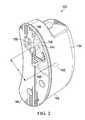
- FIG. 2illustrates a perspective view of one illustrative embodiment of a multi-orientation canister, with a portion shown with hidden lines, for use with the reduced pressure treatment system illustrated in FIG. 1 ;
- FIG. 3illustrates a perspective, exploded view of the multi-orientation canister illustrated in FIG. 2 ;
- FIG. 4illustrates another perspective, exploded view of the multi-orientation canister illustrated in FIG. 2 ;
- FIG. 5illustrates a perspective view of the multi-orientation canister of FIG. 2 with a back face plate and the attached clip removed;
- FIG. 6illustrates a sectional view of the multi-orientation canister of FIG. 5 taken along line 6 - 6 ;
- FIG. 7illustrates a sectional view of the multi-orientation canister of FIG. 5 taken along line 7 - 7 .
- reduced pressuregenerally refers to a pressure less than the ambient pressure at a tissue site that is being subjected to treatment. In most cases, this reduced pressure will be less than the atmospheric pressure at which the patient is located. Alternatively, the reduced pressure may be less than a hydrostatic pressure associated with tissue at the tissue site. Although the terms “vacuum” and “negative pressure” may be used to describe the pressure applied to the tissue site, the actual pressure reduction applied to the tissue site may be significantly less than the pressure reduction normally associated with a complete vacuum. Reduced pressure may initially generate fluid flow in the area of the tissue site. As the hydrostatic pressure around the tissue site approaches the desired reduced pressure, the flow may subside, and the reduced pressure is then maintained. Unless otherwise indicated, values of pressure stated herein are gauge pressures. Similarly, references to increases in reduced pressure typically refer to a decrease in absolute pressure, while decreases in reduced pressure typically refer to an increase in absolute pressure.
- Reduced pressure treatment systemsoften use canisters for collecting exudate, including liquids and other fluids, received from a tissue site undergoing reduced pressure tissue treatment.
- Exudate collected within the canistermay move within the canister by way of splashing or sloshing for a number of reasons. For example, when the exudate enters the canister, they may splash or foam within the canister enclosure. Likewise, once the exudate has entered the canister, the exudate may slosh due to canister movement. In some circumstances, the canister is worn by a patient and may be subject to orientation changes as the patient bends over or moves in general. The movement of the exudate within the canister may cause the exudate to come into contact with a filter used to protect the reduced pressure source from contamination.
- the filtermay be positioned within the canister to block unwanted liquids from contaminating the reduced pressure source.
- wound exudate contacts the filtereven if the contact is brief, such as when the filter is splashed by exudate or the canister undergoes a brief orientation change due to patient movement, the exudate may leave a protein film or deposit on the filter.
- the protein depositscan build-up on the filter as the filter is subject to repeated and prolonged contact with exudate, compromising the filter's ability to allow air flow between the canister and the reduced pressure source.
- a blocked or compromised filtercan create at least two problems.
- the first problemis that restricting air flow between the canister and the reduced pressure source causes air flow restriction at the wound site. Restricting the ability of the reduced pressure system from drawing air from the tissue site results in an inability to maintain reduced pressure at the tissue site.
- the other problemis that when the air flow between the canister and the reduced pressure source is restricted, an alarm may sound indicating that the canister is full and needs to be emptied or changed, when, in fact, the canister is not full.
- Reduced pressure therapy systemsmay have an alarm indicating that a canister is full based on reduced pressure no longer being supplied to the tissue site at a desired treatment level.
- tissue sitemay refer to a wound or defect located on or within any tissue, including but not limited to, bone tissue, adipose tissue, muscle tissue, neural tissue, dermal tissue, vascular tissue, connective tissue, cartilage, tendons, or ligaments.
- tissue sitemay further refer to areas of any tissue that are not necessarily wounded or defective, but are instead areas in which it is desired to add or promote the growth of additional tissue.
- reduced pressure tissue treatmentmay be used in certain tissue areas to grow additional tissue that may be harvested and transplanted to another tissue location.
- the dressing 104may include a manifold 112 placed proximate the tissue site 102 , a reduced pressure interface 114 fluidly coupled to the manifold 112 , and a drape 116 .
- the drape 116may be placed over the manifold 112 to secure the manifold 112 at the tissue site 102 and to create a fluidly sealed space 113 that is located beneath the drape and that is at least partially occupied by the manifold 112 .
- the drape 116extends beyond a perimeter of the tissue site 102 and is placed over a patient's epidermis 118 to create the fluidly sealed space 113 between the drape 116 and the epidermis 118 .
- the drape 116may include an adhesive 120 or bonding agent to secure the drape 116 to the epidermis 118 .
- the adhesive 120may be used to create a seal between the drape 116 and the epidermis 118 to prevent leakage of reduced pressure from the tissue site 102 .
- a seal layer(not shown) such as, for example, a hydrogel or other material may be disposed between the drape 116 and the epidermis 118 to augment or substitute for the sealing properties of the adhesive 120 .
- “fluid seal”means a seal adequate to maintain reduced pressure at a desired site given the particular reduced pressure source involved.
- manifoldgenerally refers to a substance or structure that is provided to assist in applying reduced pressure to, delivering fluids to, or removing fluids from the tissue site 102 .
- the manifold 112typically includes a plurality of flow channels or pathways that distribute fluids provided to and removed from the tissue site around the manifold 112 .
- the flow channels or pathwaysare interconnected to improve distribution of fluids provided or removed from the tissue site 102 .
- manifolds 112may include, for example, without limitation, devices that have structural elements arranged to form flow channels, such as, for example, cellular foam, open-cell foam, porous tissue collections, liquids, gels, and foams that include, or cure to include, flow channels.
- the manifold 112is a porous foam and includes a plurality of interconnected cells or pores that act as flow channels.
- the porous foammay be a polyurethane, open-cell, reticulated foam such as GranuFoam® material manufactured by Kinetic Concepts, Incorporated of San Antonio, Tex. Other embodiments may include “closed cells.”
- the reduced pressure interface 114may be positioned adjacent to or coupled to the drape 116 to provide fluid access to the manifold 112 .
- the reduced pressure interface 114may be coupled to the drape 116 by an adhesive 121 similar to the adhesive 120 described above.
- the conduit 110 and the reduced pressure connector 108fluidly couple the reduced pressure treatment unit 106 and the reduced pressure interface 114 .
- the reduced pressure interface 114allows the reduced pressure to be delivered to the tissue site 102 . While the amount and nature of reduced pressure applied to the tissue site 102 will typically vary according to the application, the reduced pressure treatment unit 106 will typically provide reduced pressure between ⁇ 5 mm Hg and ⁇ 500 mm Hg and more typically between ⁇ 100 mm Hg and ⁇ 300 mm Hg.
- the reduced pressure treatment unit 106may include a canister 122 for collecting exudate and a sensing unit 130 in fluid communication with a reduced pressure source 124 . While FIG. 1 illustrates that the reduced pressure treatment unit 106 houses the canister 122 , the sensing unit 130 , and the reduced pressure source 124 in a single housing unit, it should be appreciated that elements of the reduced pressure treatment unit 106 , which may include the canister 122 , the sensing unit 130 , and the reduced pressure source 124 , may be located in a number of different housing units that are fluidly connected (not shown). The canister 122 will be discussed in more detail below.
- the conduit 110may be a multi-lumen conduit or tube that provides a continuous conduit between the reduced pressure interface 114 and the reduced pressure connector 108 positioned on the reduced pressure treatment unit 106 . While the conduit 110 illustrates multiple lumens, it should be appreciated that the reduced pressure treatment system 100 may operate using a single lumen tube.
- the conduit 110may include conduits for carrying reduced pressure and removing liquids alone or may be combined with one or more lumens for sensing pressure and providing a vent or a purging capability.
- the conduit 110may include a main lumen 126 and one or more ancillary lumens 128 and is adapted to maintain fluid isolation between the main lumen 126 and the one or more ancillary lumens 128 .
- Liquids or exudate communicated from the manifold 112 through the main lumen 126are removed from the conduit 110 and retained within the canister 122 .
- the one or more ancillary lumens 128fluidly communicate reduced pressure levels from the tissue site 102 to the sensing unit 130 .
- the reduced pressure source 124is an electrically-driven vacuum pump.
- the reduced pressure source 124may instead be a manually-actuated or manually-charged pump that does not require electrical power.
- the reduced pressure source 124instead may be any other type of reduced pressure pump, or alternatively a wall suction port such as those available in hospitals and other medical facilities.
- the reduced pressure source 124may be housed within or used in conjunction with the reduced pressure treatment unit 106 , which may also contain sensors, processing units, alarm indicators, memory, databases, software, display units, and user interfaces 132 that further facilitate the application of reduced pressure treatment to the tissue site 102 .
- pressure-detection sensorslocated in the sensing unit 130 may be disposed at or near the reduced pressure source 124 .
- the pressure-detection sensorsmay receive pressure data from the reduced pressure interface 114 via the one or more ancillary lumens 128 that are dedicated to delivering reduced pressure data to the pressure-detection sensors.
- the pressure-detection sensorsmay communicate with a processing unit that monitors and controls the reduced pressure that is delivered by the reduced pressure source 124 .
- the canister 122is adapted to function in a number of different orientations, and, thus, the canister 122 may be referred to as a multi-orientation canister.
- the canister 122will generally have a primary operating orientation that will maximize the canister's 122 operational capacity during reduced pressure tissue treatments. Maximizing the canister's 122 operational capacity includes maximizing the life span of any filters used in the canister 122 , reducing or eliminating false canister-full alarms, and maximizing the canister's 122 volumetric capacity for exudate storage.
- the canister 122is defined by one or more canister walls 134 arranged to create an enclosure 136 .
- the one or more canister walls 134may generally define the exterior of the canister 122 .
- the canister 122includes an inlet 138 , a main chamber 140 , a filter chamber 142 , and an outlet 144 .
- the canister 122is in its primary operating orientation when the inlet 138 is generally positioned superior to the main chamber 140 and the filter chamber 142 .
- the canister 122may be formed in a number of different ways and from a number of different materials. As illustrated, with particular clarity in the exploded view of FIGS. 3 and 4 , the canister 122 may be formed or assembled by joining a main body 162 with a back face plate 164 . In one embodiment, the main body 162 and the back face plate 164 may be joined by a tongue-and-groove fitting. In another embodiment, the main body 162 and the back face plate 164 may be joined by and adhesive. Pre-assembled, the main body 162 may have a number of recesses, such as recesses 166 and 168 . Likewise, the back face plate 164 may have number of protrusions, such as protrusions 170 and 172 .
- the recesses 166 and 168may receive the protrusions 170 and 172 , respectively.
- the joining of the recesses 166 , 168 with the protrusions 170 , 172define the main chamber 140 and the filter chamber 142 .
- the joiningmay further define one or more apertures that provide fluid communication between the main chamber 140 and the filter chamber 142 .
- the main body 162may have interior walls that are preformed to define the perimeters of the main chamber 140 and the filter chamber 142 .
- the interior wallsmay further include preformed apertures that provide fluid communication between the main chamber 140 and the filter chamber 142 .
- the back face plate 164does not include any protrusions that function to substantively join with the main body 162 to form the interior walls that define the main chamber 140 and the filter chamber 142 .
- the inlet 138is fluidly connected with the tissue site 102 and is capable of receiving exudate from the tissue site 102 .
- the main chamber 140is in fluid communication with the inlet 138 and is adapted to receive exudate from the inlet 138 .
- the canister 122may further include a receiving chamber 146 positioned between the inlet 138 and the main chamber 140 .
- the receiving chamber 146may be configured so as to inhibit exudate from splashing when the exudate is transferred from the inlet 138 to the main chamber 140 .
- a baffle(not shown) may be positioned adjacent the inlet 138 to inhibit the splashing of exudate as the exudate enters the canister 122 through the inlet 138 .
- a bafflemay be positioned adjacent the receiving chamber 146 to provide an additional mechanism to reduced exudate splash.
- the receiving chamber 146includes an aperture 148 for providing fluid communication between the receiving chamber 146 and the main chamber 140 .
- the main chamber 140receives fluids from the inlet 138 .
- a gelling agent(not shown) may be positioned within the main chamber 140 .
- the gelling agentmay form a gel upon contact with exudate received from the tissue site 102 .
- the gel formed from the combination of the gelling agent and the exudatemay help prevent the exudate from splashing around within the canister 122 when the canister 122 is moved.
- the filter chamber 142is separated from the main chamber 140 by one or more filter chamber walls 150 or partitions.
- the recesses 166 , 168 of the main body 162may join with the protrusions 170 , 172 of the back face plate 164 to form the one or more filter chamber walls 150 .
- the filter chamber walls 150fluidly separate the main chamber 140 from the filter chamber 142 .
- the filter chamber 142is defined by at least a first filter chamber wall 156 and a second filter chamber wall 158 .
- the recess 166may join with the protrusion 170 to form the first filter chamber wall 156
- the recess 168may join with the protrusion 172 to form the second filter chamber wall 158 .
- the first filter chamber wall 156may be substantially normal to the second filter chamber wall 158 .
- the one or more filter chamber walls 150may intersect with a centroid 160 of the canister 122 .
- the “centroid” referred to hereinis the geometric enter of the canister's 122 three-dimensional shape based on an average of all points on the canister 122 .
- the geometric centermay coincide with the canister's 122 center of mass, however, the geometric center is not required to coincide with the center of mass.
- the first filter chamber wall 156may intersect the centroid 160 of the canister 122 .
- the one or more filter chamber walls 150may include or define a first aperture 152 and a second aperture 154 .
- the first and second apertures 152 , 154may be formed in a number of different shapes. In specific, non-limiting examples, the first and second apertures 152 , 154 may be round or square.
- the first aperture 152may be formed through the first filter chamber wall 156 and the second aperture 154 may be formed through the second filter chamber wall 158 .
- the first aperture 152is a distance, D, from the second aperture 154 in three-dimensional space.
- the first aperture 152is configured to provide a first path of fluid communication between the main chamber 140 and the filter chamber 142 .
- the second aperture 154is configured to provide another path of fluid communication between the main chamber 140 and the filter chamber 142 .
- the first aperture 152is configured to provide the primary path of fluid communication between the main chamber 140 and the filter chamber 142 .
- the first aperture 152is a first size and the second aperture 154 is a second size. In one embodiment, the first aperture 152 is larger than the second aperture 154 . In another embodiment, the first aperture 152 is the same size as the second aperture 154 .
- the size of the first and second apertures 152 , 154are configured to prevent fluid, upon entering the main chamber 140 , from inadvertently splashing or contacting the interior of the filter chamber 142 . In another embodiment, the size of the first and second apertures 152 , 154 , are configured to prevent gel from entering the filter chamber 142 due to splashing or sloshing.
- the first aperture 152may be positioned on or adjacent the canister's 122 centroid 160 .
- the first aperture 152may be positioned through the first filter chamber wall 156 in a location that is not adjacent to the one or more canister walls 134 that define the exterior of the canister 122 to inhibit exudate from entering the first aperture 152 as a result of exudate sloshing or splashing.
- the first aperture 152may be spaced apart from the one or more canister walls 134 .
- the second aperture 154may be positioned through the second filter chamber wall 158 in a location that maximizes the distance between the first aperture 152 and the second aperture 154 .
- the second aperture 154may be positioned through the second filter chamber wall 158 as close to the top of the main chamber 140 as possible when the canister 122 is viewed in its primary operating orientation.
- the outlet 144is positioned adjacent the filter chamber 142 through the one or more canister walls 134 .
- the outlet 144is adapted to provide fluid communication between the reduced pressure source 124 and the filter chamber 142 .
- a filter(not shown) is positioned within the filter chamber 142 .
- the filterwill typically be a hydrophobic filter to prevent exudate and liquids from exiting the canister 122 and reaching the reduced pressure source 124 .
- a liquid-air separatormay be placed between the filter and the reduced pressure source 124 for additional protection of the reduced pressure source 124 .
- the reduced pressure source 124supplies reduced pressure to the tissue site 102 via a fluid communication path linking the reduced pressure source 124 and the tissue site 102 .
- the manifold 112 , the reduced pressure interface 114 , the conduit 110 , and the canister 122are all part of the fluid communication path linking the reduced pressure source 124 to the tissue site 102 .
- exudateincluding liquids, is removed from the tissue site 102 and deposited within the canister 122 for storage. The exudate is first deposited in the main chamber 140 of the canister 122 .
- the reduced pressureis supplied to the canister 122 via the outlet 144 that is in fluid communication with the filter chamber 142 .
- the filter chamber 142is in fluid communication with the main chamber 140 by means of the first aperture 152 and the second aperture 154 .
- the second aperture 154may be significantly smaller than the first aperture 152 such that the first aperture 152 is generally the path of least resistance for fluid communication between the filter chamber 142 and the main chamber 140 . In the canister's 122 primary operating orientation, the second aperture 154 may be above or superior in position to the first aperture 152 .
- reduced pressureis mainly supplied from the filter chamber 142 to the main chamber 140 by way of the first aperture 152 because the first aperture 152 generally presents the path of least resistance.
- the first aperture 152may become occluded as the fluid level in the main chamber 140 reaches the first aperture 152 .
- the first aperturemay be occluded as a result of surface tensions.
- the second aperture 154becomes the path of least resistance between the filter chamber 142 and the main chamber 140 . Fluid will continue to fill the main chamber 140 until the fluid level reaches the second aperture 154 , occluding or blocking the second aperture 154 .
- the path of least resistance between the filter chamber 142 and the main chamber 140is again through the first aperture 152 . Sufficient pressure is created within the filter chamber 142 to cause the fluid in the main chamber 140 to be pulled into the filter chamber 142 though the first aperture 152 .
- Fluidmay continue filling the filter chamber 142 until the fluid level in the filter chamber 142 fills, blocking the filter and outlet 144 .
- the configuration of the canister 122increases the useful life span of the filter by limiting the filter's exposure to exudate before the canister 122 is full. Additionally, the configuration of the canister 122 increases the canister's useful volumetric capacity for storing exudate by filling the main chamber 140 with fluids before the filter chamber 142 is filled with fluids.
- fluids that have entered the filter chamber 142 due to movement of the canister 122may be removed or drained from the filter chamber 142 .
- Fluids received from the tissue site 102are deposited into the main chamber 140 of the canister 122 .
- the canister 122may be moved during operation causing the canister 122 to be rotated into a first position, away from the canister's 122 primary operating orientation.
- the rotation of the canister 122may cause fluids in the main chamber 140 to flow into the filter chamber 142 through either the first aperture 152 or the second aperture 154 .
- the second aperture 154being superior in position to the first aperture 152 when the canister 122 is positioned in its primary operating orientation.
- the canister 122is then rotated back into a second position, substantially aligned with the canister's 122 primary operating orientation, the configuration of the canister 122 in general, and the placement of the apertures 152 , 154 specifically, allows fluids in the filter chamber 142 to flow back into the main chamber 140 through the first aperture 152 .
- the useful life of the filter positioned in the canister 122may be extended. Fluids from the tissue site 102 are received into the main chamber 140 of the canister 122 . The fluids may react with a gelling agent contained within the main chamber 140 to create a gel. Reduced pressure from the reduced pressure source 124 may be applied to the main chamber 140 via the first aperture 152 until a fluid or gel level in the main chamber 140 covers or reaches the first aperture 152 , causing a temporary blockage of the first aperture 152 . In response to the first aperture 152 becoming temporarily blocked, reduced pressure is supplied to the main chamber 140 via the second aperture 154 until the fluid or gel level in the main chamber 140 covers or reaches the second aperture 154 .
- the second aperture 154is superior in position to the first aperture 152 when the canister 122 is positioned in its primary operating orientation. Additionally, the second aperture 154 is significantly smaller is size than the first aperture 152 such that the first aperture 152 generally provides the path of least resistance unless only the first aperture 152 is blocked.
- reduced pressureis again applied to the main chamber 140 through the first aperture 152 causing the gel in the main chamber 140 to be pulled into the filter chamber 142 until both the main chamber 140 and the filter chamber 142 are substantially full of gel.
- the second aperture 154is substantially the same size as the first aperture 152 .
- the second aperture 154becomes the path of least resistance.
- reduced pressureis applied to the main chamber 140 through both the first and second apertures 152 , 154 causing the liquid or gel in the main chamber 140 to be pulled into the filter chamber 142 until both the main chamber 140 and the filter chamber 142 are substantially full of liquid or gel.
- the canister 122is referred to as a liquid-collection canister.
- the liquid-collection canisterincludes a first and second chamber fluidly isolated from one another by one or more walls.
- the first chambermay be a main chamber similar to the main chamber 140 and the second chamber may be a filter chamber similar to the filter chamber 142 .
- a plurality of aperturesmay be positioned in the one or more walls to provide fluid communication between the first and second chambers.
- the liquid-collection canistermay further include an inlet capable of receiving fluids from a tissue site. The inlet is adapted to provide fluid communication between the tissue site and the first chamber.
- One aperture of the plurality of aperturesmay be positioned in a plane perpendicular to another of the plurality of apertures.
- the one aperturemay have a first diameter larger than a second diameter of the another of the plurality of apertures.
- the one aperturemay be positioned below the another aperture in the liquid-collection canister's primary operating orientation.
- the liquid-collection canistermay further include an outlet for providing fluid communication with the second chamber such that the outlet is adapted to be fluidly connected to a reduced pressure source.
Landscapes
- Health & Medical Sciences (AREA)
- Heart & Thoracic Surgery (AREA)
- Vascular Medicine (AREA)
- Engineering & Computer Science (AREA)
- Anesthesiology (AREA)
- Biomedical Technology (AREA)
- Hematology (AREA)
- Life Sciences & Earth Sciences (AREA)
- Animal Behavior & Ethology (AREA)
- General Health & Medical Sciences (AREA)
- Public Health (AREA)
- Veterinary Medicine (AREA)
- Media Introduction/Drainage Providing Device (AREA)
- External Artificial Organs (AREA)
Abstract
Description
Claims (25)
Priority Applications (3)
| Application Number | Priority Date | Filing Date | Title |
|---|---|---|---|
| US14/271,991US9987401B2 (en) | 2012-02-21 | 2014-05-07 | Multi-orientation canister for use with a reduced pressure treatment system |
| US15/971,873US10898621B2 (en) | 2012-02-21 | 2018-05-04 | Multi-orientation canister for use with a reduced pressure treatment system |
| US17/126,886US20210113745A1 (en) | 2012-02-21 | 2020-12-18 | Multi-Orientation Canister For Use With A Reduced Pressure Treatment System |
Applications Claiming Priority (2)
| Application Number | Priority Date | Filing Date | Title |
|---|---|---|---|
| US13/401,433US8758315B2 (en) | 2012-02-21 | 2012-02-21 | Multi-orientation canister for use with a reduced pressure treatment system |
| US14/271,991US9987401B2 (en) | 2012-02-21 | 2014-05-07 | Multi-orientation canister for use with a reduced pressure treatment system |
Related Parent Applications (1)
| Application Number | Title | Priority Date | Filing Date |
|---|---|---|---|
| US13/401,433DivisionUS8758315B2 (en) | 2012-02-21 | 2012-02-21 | Multi-orientation canister for use with a reduced pressure treatment system |
Related Child Applications (1)
| Application Number | Title | Priority Date | Filing Date |
|---|---|---|---|
| US15/971,873ContinuationUS10898621B2 (en) | 2012-02-21 | 2018-05-04 | Multi-orientation canister for use with a reduced pressure treatment system |
Publications (2)
| Publication Number | Publication Date |
|---|---|
| US20140303577A1 US20140303577A1 (en) | 2014-10-09 |
| US9987401B2true US9987401B2 (en) | 2018-06-05 |
Family
ID=48982814
Family Applications (4)
| Application Number | Title | Priority Date | Filing Date |
|---|---|---|---|
| US13/401,433Active2032-03-09US8758315B2 (en) | 2012-02-21 | 2012-02-21 | Multi-orientation canister for use with a reduced pressure treatment system |
| US14/271,991Active2033-07-09US9987401B2 (en) | 2012-02-21 | 2014-05-07 | Multi-orientation canister for use with a reduced pressure treatment system |
| US15/971,873Active2033-01-29US10898621B2 (en) | 2012-02-21 | 2018-05-04 | Multi-orientation canister for use with a reduced pressure treatment system |
| US17/126,886AbandonedUS20210113745A1 (en) | 2012-02-21 | 2020-12-18 | Multi-Orientation Canister For Use With A Reduced Pressure Treatment System |
Family Applications Before (1)
| Application Number | Title | Priority Date | Filing Date |
|---|---|---|---|
| US13/401,433Active2032-03-09US8758315B2 (en) | 2012-02-21 | 2012-02-21 | Multi-orientation canister for use with a reduced pressure treatment system |
Family Applications After (2)
| Application Number | Title | Priority Date | Filing Date |
|---|---|---|---|
| US15/971,873Active2033-01-29US10898621B2 (en) | 2012-02-21 | 2018-05-04 | Multi-orientation canister for use with a reduced pressure treatment system |
| US17/126,886AbandonedUS20210113745A1 (en) | 2012-02-21 | 2020-12-18 | Multi-Orientation Canister For Use With A Reduced Pressure Treatment System |
Country Status (1)
| Country | Link |
|---|---|
| US (4) | US8758315B2 (en) |
Cited By (4)
| Publication number | Priority date | Publication date | Assignee | Title |
|---|---|---|---|---|
| US20180250448A1 (en)* | 2012-02-21 | 2018-09-06 | Kci Licensing, Inc. | Multi-Orientation Canister For Use With A Reduced Pressure Treatment System |
| USD935035S1 (en)* | 2020-03-05 | 2021-11-02 | Deroyal Industries, Inc. | Negative pressure wound therapy canister |
| USD935034S1 (en)* | 2020-03-05 | 2021-11-02 | Deroyal Industries, Inc. | Negative pressure wound therapy canister |
| USD935033S1 (en)* | 2020-03-05 | 2021-11-02 | Deroyal Industries, Inc. | Negative pressure wound therapy canister |
Families Citing this family (22)
| Publication number | Priority date | Publication date | Assignee | Title |
|---|---|---|---|---|
| EP2852333B1 (en) | 2012-05-22 | 2021-12-15 | Smith & Nephew plc | Apparatuses for wound therapy |
| US9737649B2 (en) | 2013-03-14 | 2017-08-22 | Smith & Nephew, Inc. | Systems and methods for applying reduced pressure therapy |
| JP2016517318A (en) | 2013-03-14 | 2016-06-16 | スミス アンド ネフュー インコーポレーテッド | System and method for administering decompression therapy |
| CN105228688B (en) | 2013-03-15 | 2019-02-19 | 伊瑟拉医疗公司 | Vascular treatment devices and methods |
| CA3179001A1 (en) | 2014-07-31 | 2016-02-04 | Smith & Nephew, Inc. | Systems and methods for applying reduced pressure therapy |
| US12133789B2 (en) | 2014-07-31 | 2024-11-05 | Smith & Nephew, Inc. | Reduced pressure therapy apparatus construction and control |
| US9770369B2 (en) | 2014-08-08 | 2017-09-26 | Neogenix, Llc | Wound care devices, apparatus, and treatment methods |
| EP3714916A1 (en) | 2015-07-29 | 2020-09-30 | Innovative Therapies Inc. | Wound therapy device pressure monitoring and control system |
| US11315681B2 (en) | 2015-10-07 | 2022-04-26 | Smith & Nephew, Inc. | Reduced pressure therapy device operation and authorization monitoring |
| CN108697423A (en) | 2016-02-16 | 2018-10-23 | 伊瑟拉医疗公司 | The part flow arrangement of suction unit and anchoring |
| CN109069713A (en) | 2016-05-13 | 2018-12-21 | 史密夫和内修有限公司 | Automatic wound in negative pressure wound treating system couples detection |
| US12263294B2 (en) | 2016-09-28 | 2025-04-01 | T.J.Smith And Nephew, Limited | Systems and methods for operating negative pressure wound therapy devices |
| WO2018064077A2 (en) | 2016-09-29 | 2018-04-05 | Smith & Nephew, Inc. | Construction and protection of components in negative pressure wound therapy systems |
| WO2018165049A1 (en) | 2017-03-07 | 2018-09-13 | Smith & Nephew, Inc. | Reduced pressure therapy systems and methods including an antenna |
| WO2018195101A1 (en) | 2017-04-19 | 2018-10-25 | Smith & Nephew, Inc. | Negative pressure wound therapy canisters |
| WO2019014141A1 (en) | 2017-07-10 | 2019-01-17 | Smith & Nephew, Inc. | Systems and methods for directly interacting with communications module of wound therapy apparatus |
| USD847864S1 (en) | 2018-01-22 | 2019-05-07 | Insera Therapeutics, Inc. | Pump |
| WO2020018328A1 (en)* | 2018-07-16 | 2020-01-23 | Kci Licensing, Inc. | Wound therapy system with conduit blockage detection |
| GB201820668D0 (en) | 2018-12-19 | 2019-01-30 | Smith & Nephew Inc | Systems and methods for delivering prescribed wound therapy |
| GB201911693D0 (en) | 2019-08-15 | 2019-10-02 | Smith & Nephew | Systems and methods for monitoring essential performance of wound therapy |
| GB201914283D0 (en) | 2019-10-03 | 2019-11-20 | Smith & Nephew | Apparatuses and methods for negative pressure wound therapy |
| US12220139B2 (en) | 2022-03-20 | 2025-02-11 | Von Vascular, Inc. | System, devices and methods for removing obstructions in body lumens |
Citations (136)
| Publication number | Priority date | Publication date | Assignee | Title |
|---|---|---|---|---|
| US1355846A (en) | 1920-02-06 | 1920-10-19 | David A Rannells | Medical appliance |
| US2547758A (en) | 1949-01-05 | 1951-04-03 | Wilmer B Keeling | Instrument for treating the male urethra |
| US2632443A (en) | 1949-04-18 | 1953-03-24 | Eleanor P Lesher | Surgical dressing |
| GB692578A (en) | 1949-09-13 | 1953-06-10 | Minnesota Mining & Mfg | Improvements in or relating to drape sheets for surgical use |
| US2682873A (en) | 1952-07-30 | 1954-07-06 | Johnson & Johnson | General purpose protective dressing |
| US2910763A (en) | 1955-08-17 | 1959-11-03 | Du Pont | Felt-like products |
| US2969057A (en) | 1957-11-04 | 1961-01-24 | Brady Co W H | Nematodic swab |
| US3066672A (en) | 1960-09-27 | 1962-12-04 | Jr William H Crosby | Method and apparatus for serial sampling of intestinal juice |
| US3367332A (en) | 1965-08-27 | 1968-02-06 | Gen Electric | Product and process for establishing a sterile area of skin |
| US3520300A (en) | 1967-03-15 | 1970-07-14 | Amp Inc | Surgical sponge and suction device |
| US3568675A (en) | 1968-08-30 | 1971-03-09 | Clyde B Harvey | Fistula and penetrating wound dressing |
| US3631654A (en)* | 1968-10-03 | 1972-01-04 | Pall Corp | Gas purge device |
| US3648692A (en) | 1970-12-07 | 1972-03-14 | Parke Davis & Co | Medical-surgical dressing for burns and the like |
| US3682180A (en) | 1970-06-08 | 1972-08-08 | Coilform Co Inc | Drain clip for surgical drain |
| US3826254A (en) | 1973-02-26 | 1974-07-30 | Verco Ind | Needle or catheter retaining appliance |
| DE2640413A1 (en) | 1976-09-08 | 1978-03-09 | Wolf Gmbh Richard | CATHETER MONITORING DEVICE |
| US4080970A (en) | 1976-11-17 | 1978-03-28 | Miller Thomas J | Post-operative combination dressing and internal drain tube with external shield and tube connector |
| US4096853A (en) | 1975-06-21 | 1978-06-27 | Hoechst Aktiengesellschaft | Device for the introduction of contrast medium into an anus praeter |
| US4139004A (en) | 1977-02-17 | 1979-02-13 | Gonzalez Jr Harry | Bandage apparatus for treating burns |
| US4165748A (en) | 1977-11-07 | 1979-08-28 | Johnson Melissa C | Catheter tube holder |
| US4184510A (en) | 1977-03-15 | 1980-01-22 | Fibra-Sonics, Inc. | Valued device for controlling vacuum in surgery |
| WO1980002182A1 (en) | 1979-04-06 | 1980-10-16 | J Moss | Portable suction device for collecting fluids from a closed wound |
| US4233969A (en) | 1976-11-11 | 1980-11-18 | Lock Peter M | Wound dressing materials |
| US4245630A (en) | 1976-10-08 | 1981-01-20 | T. J. Smith & Nephew, Ltd. | Tearable composite strip of materials |
| US4256109A (en) | 1978-07-10 | 1981-03-17 | Nichols Robert L | Shut off valve for medical suction apparatus |
| US4261363A (en) | 1979-11-09 | 1981-04-14 | C. R. Bard, Inc. | Retention clips for body fluid drains |
| US4275721A (en) | 1978-11-28 | 1981-06-30 | Landstingens Inkopscentral Lic, Ekonomisk Forening | Vein catheter bandage |
| US4284079A (en) | 1979-06-28 | 1981-08-18 | Adair Edwin Lloyd | Method for applying a male incontinence device |
| US4297995A (en) | 1980-06-03 | 1981-11-03 | Key Pharmaceuticals, Inc. | Bandage containing attachment post |
| US4333468A (en) | 1980-08-18 | 1982-06-08 | Geist Robert W | Mesentery tube holder apparatus |
| US4373519A (en) | 1981-06-26 | 1983-02-15 | Minnesota Mining And Manufacturing Company | Composite wound dressing |
| US4382441A (en) | 1978-12-06 | 1983-05-10 | Svedman Paul | Device for treating tissues, for example skin |
| US4392858A (en) | 1981-07-16 | 1983-07-12 | Sherwood Medical Company | Wound drainage device |
| US4392853A (en) | 1981-03-16 | 1983-07-12 | Rudolph Muto | Sterile assembly for protecting and fastening an indwelling device |
| US4419097A (en) | 1981-07-31 | 1983-12-06 | Rexar Industries, Inc. | Attachment for catheter tube |
| EP0100148A1 (en) | 1982-07-06 | 1984-02-08 | Dow Corning Limited | Medical-surgical dressing and a process for the production thereof |
| US4465485A (en) | 1981-03-06 | 1984-08-14 | Becton, Dickinson And Company | Suction canister with unitary shut-off valve and filter features |
| EP0117632A2 (en) | 1983-01-27 | 1984-09-05 | Johnson & Johnson Products Inc. | Adhesive film dressing |
| US4475909A (en) | 1982-05-06 | 1984-10-09 | Eisenberg Melvin I | Male urinary device and method for applying the device |
| US4480638A (en) | 1980-03-11 | 1984-11-06 | Eduard Schmid | Cushion for holding an element of grafted skin |
| US4525166A (en) | 1981-11-21 | 1985-06-25 | Intermedicat Gmbh | Rolled flexible medical suction drainage device |
| US4525374A (en) | 1984-02-27 | 1985-06-25 | Manresa, Inc. | Treating hydrophobic filters to render them hydrophilic |
| US4540412A (en) | 1983-07-14 | 1985-09-10 | The Kendall Company | Device for moist heat therapy |
| US4543100A (en) | 1983-11-01 | 1985-09-24 | Brodsky Stuart A | Catheter and drain tube retainer |
| US4548202A (en) | 1983-06-20 | 1985-10-22 | Ethicon, Inc. | Mesh tissue fasteners |
| US4551139A (en) | 1982-02-08 | 1985-11-05 | Marion Laboratories, Inc. | Method and apparatus for burn wound treatment |
| EP0161865A2 (en) | 1984-05-03 | 1985-11-21 | Smith and Nephew Associated Companies p.l.c. | Adhesive wound dressing |
| US4569348A (en) | 1980-02-22 | 1986-02-11 | Velcro Usa Inc. | Catheter tube holder strap |
| AU550575B2 (en) | 1981-08-07 | 1986-03-27 | Richard Christian Wright | Wound drainage device |
| US4605399A (en) | 1984-12-04 | 1986-08-12 | Complex, Inc. | Transdermal infusion device |
| US4608041A (en) | 1981-10-14 | 1986-08-26 | Frese Nielsen | Device for treatment of wounds in body tissue of patients by exposure to jets of gas |
| US4640688A (en) | 1985-08-23 | 1987-02-03 | Mentor Corporation | Urine collection catheter |
| US4655754A (en) | 1984-11-09 | 1987-04-07 | Stryker Corporation | Vacuum wound drainage system and lipids baffle therefor |
| US4664662A (en) | 1984-08-02 | 1987-05-12 | Smith And Nephew Associated Companies Plc | Wound dressing |
| WO1987004626A1 (en) | 1986-01-31 | 1987-08-13 | Osmond, Roger, L., W. | Suction system for wound and gastro-intestinal drainage |
| US4710165A (en) | 1985-09-16 | 1987-12-01 | Mcneil Charles B | Wearable, variable rate suction/collection device |
| US4733659A (en) | 1986-01-17 | 1988-03-29 | Seton Company | Foam bandage |
| GB2195255A (en) | 1986-09-30 | 1988-04-07 | Vacutec Uk Limited | Method and apparatus for vacuum treatment of an epidermal surface |
| US4743232A (en) | 1986-10-06 | 1988-05-10 | The Clinipad Corporation | Package assembly for plastic film bandage |
| GB2197789A (en) | 1986-11-28 | 1988-06-02 | Smiths Industries Plc | Anti-foaming disinfectants used in surgical suction apparatus |
| US4758220A (en) | 1985-09-26 | 1988-07-19 | Alcon Laboratories, Inc. | Surgical cassette proximity sensing and latching apparatus |
| US4787888A (en) | 1987-06-01 | 1988-11-29 | University Of Connecticut | Disposable piezoelectric polymer bandage for percutaneous delivery of drugs and method for such percutaneous delivery (a) |
| US4826494A (en) | 1984-11-09 | 1989-05-02 | Stryker Corporation | Vacuum wound drainage system |
| US4838883A (en) | 1986-03-07 | 1989-06-13 | Nissho Corporation | Urine-collecting device |
| US4840187A (en) | 1986-09-11 | 1989-06-20 | Bard Limited | Sheath applicator |
| US4863449A (en) | 1987-07-06 | 1989-09-05 | Hollister Incorporated | Adhesive-lined elastic condom cathether |
| US4872450A (en) | 1984-08-17 | 1989-10-10 | Austad Eric D | Wound dressing and method of forming same |
| US4878901A (en) | 1986-10-10 | 1989-11-07 | Sachse Hans Ernst | Condom catheter, a urethral catheter for the prevention of ascending infections |
| US4886492A (en)* | 1987-03-24 | 1989-12-12 | Brooke Gerard M | Surgical suction tip with filter |
| GB2220357A (en) | 1988-05-28 | 1990-01-10 | Smiths Industries Plc | Medico-surgical containers |
| US4897081A (en) | 1984-05-25 | 1990-01-30 | Thermedics Inc. | Percutaneous access device |
| US4906240A (en) | 1988-02-01 | 1990-03-06 | Matrix Medica, Inc. | Adhesive-faced porous absorbent sheet and method of making same |
| US4906233A (en) | 1986-05-29 | 1990-03-06 | Terumo Kabushiki Kaisha | Method of securing a catheter body to a human skin surface |
| US4919654A (en) | 1988-08-03 | 1990-04-24 | Kalt Medical Corporation | IV clamp with membrane |
| CA2005436A1 (en) | 1988-12-13 | 1990-06-13 | Glenda G. Kalt | Transparent tracheostomy tube dressing |
| US4941882A (en) | 1987-03-14 | 1990-07-17 | Smith And Nephew Associated Companies, P.L.C. | Adhesive dressing for retaining a cannula on the skin |
| US4953565A (en) | 1986-11-26 | 1990-09-04 | Shunro Tachibana | Endermic application kits for external medicines |
| US4957492A (en)* | 1988-12-07 | 1990-09-18 | Cabot Medical Corporation | Apparatus for collecting and handling tissue during uterine evacuation procedure |
| WO1990010424A1 (en) | 1989-03-16 | 1990-09-20 | Smith & Nephew Plc | Absorbent devices and precursors therefor |
| US4969880A (en) | 1989-04-03 | 1990-11-13 | Zamierowski David S | Wound dressing and treatment method |
| US4985019A (en) | 1988-03-11 | 1991-01-15 | Michelson Gary K | X-ray marker |
| GB2235877A (en) | 1989-09-18 | 1991-03-20 | Antonio Talluri | Closed wound suction apparatus |
| US5037397A (en) | 1985-05-03 | 1991-08-06 | Medical Distributors, Inc. | Universal clamp |
| US5086170A (en) | 1989-01-16 | 1992-02-04 | Roussel Uclaf | Process for the preparation of azabicyclo compounds |
| US5092858A (en) | 1990-03-20 | 1992-03-03 | Becton, Dickinson And Company | Liquid gelling agent distributor device |
| US5100396A (en) | 1989-04-03 | 1992-03-31 | Zamierowski David S | Fluidic connection system and method |
| JPH04129536A (en) | 1990-09-19 | 1992-04-30 | Terumo Corp | Balance device |
| US5134994A (en) | 1990-02-12 | 1992-08-04 | Say Sam L | Field aspirator in a soft pack with externally mounted container |
| US5149331A (en) | 1991-05-03 | 1992-09-22 | Ariel Ferdman | Method and device for wound closure |
| US5167613A (en) | 1992-03-23 | 1992-12-01 | The Kendall Company | Composite vented wound dressing |
| US5176663A (en) | 1987-12-02 | 1993-01-05 | Pal Svedman | Dressing having pad with compressibility limiting elements |
| WO1993009727A1 (en) | 1991-11-14 | 1993-05-27 | Wake Forest University | Method and apparatus for treating tissue damage |
| US5215522A (en) | 1984-07-23 | 1993-06-01 | Ballard Medical Products | Single use medical aspirating device and method |
| US5232453A (en) | 1989-07-14 | 1993-08-03 | E. R. Squibb & Sons, Inc. | Catheter holder |
| US5261893A (en) | 1989-04-03 | 1993-11-16 | Zamierowski David S | Fastening system and method |
| US5278100A (en) | 1991-11-08 | 1994-01-11 | Micron Technology, Inc. | Chemical vapor deposition technique for depositing titanium silicide on semiconductor wafers |
| US5279550A (en) | 1991-12-19 | 1994-01-18 | Gish Biomedical, Inc. | Orthopedic autotransfusion system |
| US5298015A (en) | 1989-07-11 | 1994-03-29 | Nippon Zeon Co., Ltd. | Wound dressing having a porous structure |
| US5342376A (en) | 1993-05-03 | 1994-08-30 | Dermagraphics, Inc. | Inserting device for a barbed tissue connector |
| US5344415A (en) | 1993-06-15 | 1994-09-06 | Deroyal Industries, Inc. | Sterile system for dressing vascular access site |
| DE4306478A1 (en) | 1993-03-02 | 1994-09-08 | Wolfgang Dr Wagner | Drainage device, in particular pleural drainage device, and drainage method |
| WO1994020041A1 (en) | 1993-03-09 | 1994-09-15 | Wake Forest University | Wound treatment employing reduced pressure |
| US5358494A (en) | 1989-07-11 | 1994-10-25 | Svedman Paul | Irrigation dressing |
| US5437651A (en) | 1993-09-01 | 1995-08-01 | Research Medical, Inc. | Medical suction apparatus |
| US5437622A (en) | 1992-04-29 | 1995-08-01 | Laboratoire Hydrex (Sa) | Transparent adhesive dressing with reinforced starter cuts |
| DE29504378U1 (en) | 1995-03-15 | 1995-09-14 | MTG Medizinisch, technische Gerätebau GmbH, 66299 Friedrichsthal | Electronically controlled low-vacuum pump for chest and wound drainage |
| WO1996005873A1 (en) | 1994-08-22 | 1996-02-29 | Kinetic Concepts Inc. | Wound drainage equipment |
| US5527293A (en) | 1989-04-03 | 1996-06-18 | Kinetic Concepts, Inc. | Fastening system and method |
| US5549584A (en) | 1994-02-14 | 1996-08-27 | The Kendall Company | Apparatus for removing fluid from a wound |
| US5556375A (en) | 1994-06-16 | 1996-09-17 | Hercules Incorporated | Wound dressing having a fenestrated base layer |
| US5607388A (en) | 1994-06-16 | 1997-03-04 | Hercules Incorporated | Multi-purpose wound dressing |
| WO1997018007A1 (en) | 1995-11-14 | 1997-05-22 | Kci Medical Limited | Portable wound treatment apparatus |
| US5779649A (en)* | 1996-12-17 | 1998-07-14 | Pabban Development, Inc. | Surgical suction wand with filter |
| WO1999013793A1 (en) | 1997-09-12 | 1999-03-25 | Kci Medical Limited | Surgical drape and suction head for wound treatment |
| US6071267A (en) | 1998-02-06 | 2000-06-06 | Kinetic Concepts, Inc. | Medical patient fluid management interface system and method |
| US6135116A (en) | 1997-07-28 | 2000-10-24 | Kci Licensing, Inc. | Therapeutic method for treating ulcers |
| US6210383B1 (en) | 1999-01-29 | 2001-04-03 | Atrium Medical Corporation | Fluid recovery system |
| US6241747B1 (en) | 1993-05-03 | 2001-06-05 | Quill Medical, Inc. | Barbed Bodily tissue connector |
| US6287316B1 (en) | 1999-03-26 | 2001-09-11 | Ethicon, Inc. | Knitted surgical mesh |
| US20020077661A1 (en) | 2000-12-20 | 2002-06-20 | Vahid Saadat | Multi-barbed device for retaining tissue in apposition and methods of use |
| US20020115951A1 (en) | 2001-02-22 | 2002-08-22 | Core Products International, Inc. | Ankle brace providing upper and lower ankle adjustment |
| EP1234589A1 (en) | 1999-11-15 | 2002-08-28 | Ichiro Shibuya | Disposable body fluid filter unit, disposable body fluid sucking device, and body fluid sucking source |
| US20020120185A1 (en) | 2000-05-26 | 2002-08-29 | Kci Licensing, Inc. | System for combined transcutaneous blood gas monitoring and vacuum assisted wound closure |
| US20020143286A1 (en) | 2001-03-05 | 2002-10-03 | Kci Licensing, Inc. | Vacuum assisted wound treatment apparatus and infection identification system and method |
| US6488643B1 (en) | 1998-10-08 | 2002-12-03 | Kci Licensing, Inc. | Wound healing foot wrap |
| US6493568B1 (en) | 1994-07-19 | 2002-12-10 | Kci Licensing, Inc. | Patient interface system |
| AU755496B2 (en) | 1997-09-12 | 2002-12-12 | Kci Licensing, Inc. | Surgical drape and suction head for wound treatment |
| US20060079852A1 (en) | 2002-12-31 | 2006-04-13 | Bubb Stephen K | Externally-applied patient interface system and method |
| US20070016152A1 (en)* | 2005-07-14 | 2007-01-18 | Boehringer Laboratories, Inc. | System for treating a wound with suction and method detecting loss of suction |
| JP4129536B2 (en) | 2000-02-24 | 2008-08-06 | ヴェネテック インターナショナル,インコーポレイテッド | Highly compatible catheter anchoring system |
| US20090221990A1 (en)* | 2008-02-29 | 2009-09-03 | Jonathan Paul Jaeb | System and method for collecting exudates |
| US20090306630A1 (en)* | 2008-06-04 | 2009-12-10 | Christopher Brian Locke | Reduced-pressure, liquid-collection canister with multi-orientation filter |
| US20110060300A1 (en)* | 2007-08-17 | 2011-03-10 | Conva Tec Technologies Inc. | Aspiration system for removing liquid discharged by the body, and liquid sensor therefor |
| US20110152799A1 (en)* | 2009-12-23 | 2011-06-23 | Bendele Kevin | Reduced-pressure, multi-orientation, liquid-collection canister |
| US20110257612A1 (en)* | 2010-04-16 | 2011-10-20 | Kci Licensing, Inc. | Reduced-pressure sources, systems, and methods employing a polymeric, porous, hydrophobic material |
| US20120046624A1 (en)* | 2010-08-18 | 2012-02-23 | Christopher Brian Locke | Reduced-pressure, multi-orientation, liquid-collection canister |
Family Cites Families (19)
| Publication number | Priority date | Publication date | Assignee | Title |
|---|---|---|---|---|
| US4516973A (en)* | 1983-03-14 | 1985-05-14 | Becton, Dickinson And Company | One-piece disposable collection bag having a rigid cover for a suction canister unit |
| US7198046B1 (en)* | 1991-11-14 | 2007-04-03 | Wake Forest University Health Sciences | Wound treatment employing reduced pressure |
| GB0011202D0 (en)* | 2000-05-09 | 2000-06-28 | Kci Licensing Inc | Abdominal wound dressing |
| US7846141B2 (en) | 2002-09-03 | 2010-12-07 | Bluesky Medical Group Incorporated | Reduced pressure treatment system |
| GB0224986D0 (en) | 2002-10-28 | 2002-12-04 | Smith & Nephew | Apparatus |
| GB0325126D0 (en) | 2003-10-28 | 2003-12-03 | Smith & Nephew | Apparatus with heat |
| GB0325120D0 (en) | 2003-10-28 | 2003-12-03 | Smith & Nephew | Apparatus with actives |
| US7909805B2 (en) | 2004-04-05 | 2011-03-22 | Bluesky Medical Group Incorporated | Flexible reduced pressure treatment appliance |
| US8529548B2 (en) | 2004-04-27 | 2013-09-10 | Smith & Nephew Plc | Wound treatment apparatus and method |
| GB0520863D0 (en)* | 2005-10-13 | 2005-11-23 | Univ Brunel | Urine collection device |
| DE202006020723U1 (en) | 2006-03-24 | 2010-04-29 | Atmos Medizintechnik Gmbh & Co. Kg | suction |
| US8460258B2 (en) | 2008-01-08 | 2013-06-11 | Southeastern Medical Technologies, Llc | Methods and apparatuses for the treatment of wounds with pressures altered from atmospheric |
| US8021347B2 (en) | 2008-07-21 | 2011-09-20 | Tyco Healthcare Group Lp | Thin film wound dressing |
| US8007481B2 (en) | 2008-07-17 | 2011-08-30 | Tyco Healthcare Group Lp | Subatmospheric pressure mechanism for wound therapy system |
| CN102036699B (en)* | 2008-05-30 | 2013-08-21 | 凯希特许有限公司 | Decompression Linear Wound Therapy System |
| US8216198B2 (en) | 2009-01-09 | 2012-07-10 | Tyco Healthcare Group Lp | Canister for receiving wound exudate in a negative pressure therapy system |
| US8251979B2 (en) | 2009-05-11 | 2012-08-28 | Tyco Healthcare Group Lp | Orientation independent canister for a negative pressure wound therapy device |
| US8366694B1 (en)* | 2009-05-22 | 2013-02-05 | Donnell Mark Jordan | Tissue refining device |
| US8758315B2 (en)* | 2012-02-21 | 2014-06-24 | Kci Licensing, Inc. | Multi-orientation canister for use with a reduced pressure treatment system |
- 2012
- 2012-02-21USUS13/401,433patent/US8758315B2/enactiveActive
- 2014
- 2014-05-07USUS14/271,991patent/US9987401B2/enactiveActive
- 2018
- 2018-05-04USUS15/971,873patent/US10898621B2/enactiveActive
- 2020
- 2020-12-18USUS17/126,886patent/US20210113745A1/ennot_activeAbandoned
Patent Citations (148)
| Publication number | Priority date | Publication date | Assignee | Title |
|---|---|---|---|---|
| US1355846A (en) | 1920-02-06 | 1920-10-19 | David A Rannells | Medical appliance |
| US2547758A (en) | 1949-01-05 | 1951-04-03 | Wilmer B Keeling | Instrument for treating the male urethra |
| US2632443A (en) | 1949-04-18 | 1953-03-24 | Eleanor P Lesher | Surgical dressing |
| GB692578A (en) | 1949-09-13 | 1953-06-10 | Minnesota Mining & Mfg | Improvements in or relating to drape sheets for surgical use |
| US2682873A (en) | 1952-07-30 | 1954-07-06 | Johnson & Johnson | General purpose protective dressing |
| US2910763A (en) | 1955-08-17 | 1959-11-03 | Du Pont | Felt-like products |
| US2969057A (en) | 1957-11-04 | 1961-01-24 | Brady Co W H | Nematodic swab |
| US3066672A (en) | 1960-09-27 | 1962-12-04 | Jr William H Crosby | Method and apparatus for serial sampling of intestinal juice |
| US3367332A (en) | 1965-08-27 | 1968-02-06 | Gen Electric | Product and process for establishing a sterile area of skin |
| US3520300A (en) | 1967-03-15 | 1970-07-14 | Amp Inc | Surgical sponge and suction device |
| US3568675A (en) | 1968-08-30 | 1971-03-09 | Clyde B Harvey | Fistula and penetrating wound dressing |
| US3631654A (en)* | 1968-10-03 | 1972-01-04 | Pall Corp | Gas purge device |
| US3682180A (en) | 1970-06-08 | 1972-08-08 | Coilform Co Inc | Drain clip for surgical drain |
| US3648692A (en) | 1970-12-07 | 1972-03-14 | Parke Davis & Co | Medical-surgical dressing for burns and the like |
| US3826254A (en) | 1973-02-26 | 1974-07-30 | Verco Ind | Needle or catheter retaining appliance |
| US4096853A (en) | 1975-06-21 | 1978-06-27 | Hoechst Aktiengesellschaft | Device for the introduction of contrast medium into an anus praeter |
| DE2640413A1 (en) | 1976-09-08 | 1978-03-09 | Wolf Gmbh Richard | CATHETER MONITORING DEVICE |
| US4245630A (en) | 1976-10-08 | 1981-01-20 | T. J. Smith & Nephew, Ltd. | Tearable composite strip of materials |
| US4233969A (en) | 1976-11-11 | 1980-11-18 | Lock Peter M | Wound dressing materials |
| US4080970A (en) | 1976-11-17 | 1978-03-28 | Miller Thomas J | Post-operative combination dressing and internal drain tube with external shield and tube connector |
| US4139004A (en) | 1977-02-17 | 1979-02-13 | Gonzalez Jr Harry | Bandage apparatus for treating burns |
| US4184510A (en) | 1977-03-15 | 1980-01-22 | Fibra-Sonics, Inc. | Valued device for controlling vacuum in surgery |
| US4165748A (en) | 1977-11-07 | 1979-08-28 | Johnson Melissa C | Catheter tube holder |
| US4256109A (en) | 1978-07-10 | 1981-03-17 | Nichols Robert L | Shut off valve for medical suction apparatus |
| US4275721A (en) | 1978-11-28 | 1981-06-30 | Landstingens Inkopscentral Lic, Ekonomisk Forening | Vein catheter bandage |
| US4382441A (en) | 1978-12-06 | 1983-05-10 | Svedman Paul | Device for treating tissues, for example skin |
| WO1980002182A1 (en) | 1979-04-06 | 1980-10-16 | J Moss | Portable suction device for collecting fluids from a closed wound |
| US4284079A (en) | 1979-06-28 | 1981-08-18 | Adair Edwin Lloyd | Method for applying a male incontinence device |
| US4261363A (en) | 1979-11-09 | 1981-04-14 | C. R. Bard, Inc. | Retention clips for body fluid drains |
| US4569348A (en) | 1980-02-22 | 1986-02-11 | Velcro Usa Inc. | Catheter tube holder strap |
| US4480638A (en) | 1980-03-11 | 1984-11-06 | Eduard Schmid | Cushion for holding an element of grafted skin |
| US4297995A (en) | 1980-06-03 | 1981-11-03 | Key Pharmaceuticals, Inc. | Bandage containing attachment post |
| US4333468A (en) | 1980-08-18 | 1982-06-08 | Geist Robert W | Mesentery tube holder apparatus |
| US4465485A (en) | 1981-03-06 | 1984-08-14 | Becton, Dickinson And Company | Suction canister with unitary shut-off valve and filter features |
| US4392853A (en) | 1981-03-16 | 1983-07-12 | Rudolph Muto | Sterile assembly for protecting and fastening an indwelling device |
| US4373519A (en) | 1981-06-26 | 1983-02-15 | Minnesota Mining And Manufacturing Company | Composite wound dressing |
| US4392858A (en) | 1981-07-16 | 1983-07-12 | Sherwood Medical Company | Wound drainage device |
| US4419097A (en) | 1981-07-31 | 1983-12-06 | Rexar Industries, Inc. | Attachment for catheter tube |
| AU550575B2 (en) | 1981-08-07 | 1986-03-27 | Richard Christian Wright | Wound drainage device |
| US4608041A (en) | 1981-10-14 | 1986-08-26 | Frese Nielsen | Device for treatment of wounds in body tissue of patients by exposure to jets of gas |
| US4525166A (en) | 1981-11-21 | 1985-06-25 | Intermedicat Gmbh | Rolled flexible medical suction drainage device |
| US4551139A (en) | 1982-02-08 | 1985-11-05 | Marion Laboratories, Inc. | Method and apparatus for burn wound treatment |
| US4475909A (en) | 1982-05-06 | 1984-10-09 | Eisenberg Melvin I | Male urinary device and method for applying the device |
| EP0100148A1 (en) | 1982-07-06 | 1984-02-08 | Dow Corning Limited | Medical-surgical dressing and a process for the production thereof |
| EP0117632A2 (en) | 1983-01-27 | 1984-09-05 | Johnson & Johnson Products Inc. | Adhesive film dressing |
| US4548202A (en) | 1983-06-20 | 1985-10-22 | Ethicon, Inc. | Mesh tissue fasteners |
| US4540412A (en) | 1983-07-14 | 1985-09-10 | The Kendall Company | Device for moist heat therapy |
| US4543100A (en) | 1983-11-01 | 1985-09-24 | Brodsky Stuart A | Catheter and drain tube retainer |
| US4525374A (en) | 1984-02-27 | 1985-06-25 | Manresa, Inc. | Treating hydrophobic filters to render them hydrophilic |
| EP0161865A2 (en) | 1984-05-03 | 1985-11-21 | Smith and Nephew Associated Companies p.l.c. | Adhesive wound dressing |
| US4897081A (en) | 1984-05-25 | 1990-01-30 | Thermedics Inc. | Percutaneous access device |
| US5215522A (en) | 1984-07-23 | 1993-06-01 | Ballard Medical Products | Single use medical aspirating device and method |
| US4664662A (en) | 1984-08-02 | 1987-05-12 | Smith And Nephew Associated Companies Plc | Wound dressing |
| US4872450A (en) | 1984-08-17 | 1989-10-10 | Austad Eric D | Wound dressing and method of forming same |
| US4826494A (en) | 1984-11-09 | 1989-05-02 | Stryker Corporation | Vacuum wound drainage system |
| US4655754A (en) | 1984-11-09 | 1987-04-07 | Stryker Corporation | Vacuum wound drainage system and lipids baffle therefor |
| US4605399A (en) | 1984-12-04 | 1986-08-12 | Complex, Inc. | Transdermal infusion device |
| US5037397A (en) | 1985-05-03 | 1991-08-06 | Medical Distributors, Inc. | Universal clamp |
| US4640688A (en) | 1985-08-23 | 1987-02-03 | Mentor Corporation | Urine collection catheter |
| US4710165A (en) | 1985-09-16 | 1987-12-01 | Mcneil Charles B | Wearable, variable rate suction/collection device |
| US4758220A (en) | 1985-09-26 | 1988-07-19 | Alcon Laboratories, Inc. | Surgical cassette proximity sensing and latching apparatus |
| US4733659A (en) | 1986-01-17 | 1988-03-29 | Seton Company | Foam bandage |
| WO1987004626A1 (en) | 1986-01-31 | 1987-08-13 | Osmond, Roger, L., W. | Suction system for wound and gastro-intestinal drainage |
| US4838883A (en) | 1986-03-07 | 1989-06-13 | Nissho Corporation | Urine-collecting device |
| US4906233A (en) | 1986-05-29 | 1990-03-06 | Terumo Kabushiki Kaisha | Method of securing a catheter body to a human skin surface |
| US4840187A (en) | 1986-09-11 | 1989-06-20 | Bard Limited | Sheath applicator |
| GB2195255A (en) | 1986-09-30 | 1988-04-07 | Vacutec Uk Limited | Method and apparatus for vacuum treatment of an epidermal surface |
| US4743232A (en) | 1986-10-06 | 1988-05-10 | The Clinipad Corporation | Package assembly for plastic film bandage |
| US4878901A (en) | 1986-10-10 | 1989-11-07 | Sachse Hans Ernst | Condom catheter, a urethral catheter for the prevention of ascending infections |
| US4953565A (en) | 1986-11-26 | 1990-09-04 | Shunro Tachibana | Endermic application kits for external medicines |
| GB2197789A (en) | 1986-11-28 | 1988-06-02 | Smiths Industries Plc | Anti-foaming disinfectants used in surgical suction apparatus |
| US4941882A (en) | 1987-03-14 | 1990-07-17 | Smith And Nephew Associated Companies, P.L.C. | Adhesive dressing for retaining a cannula on the skin |
| US4886492A (en)* | 1987-03-24 | 1989-12-12 | Brooke Gerard M | Surgical suction tip with filter |
| US4787888A (en) | 1987-06-01 | 1988-11-29 | University Of Connecticut | Disposable piezoelectric polymer bandage for percutaneous delivery of drugs and method for such percutaneous delivery (a) |
| US4863449A (en) | 1987-07-06 | 1989-09-05 | Hollister Incorporated | Adhesive-lined elastic condom cathether |
| US5176663A (en) | 1987-12-02 | 1993-01-05 | Pal Svedman | Dressing having pad with compressibility limiting elements |
| US4906240A (en) | 1988-02-01 | 1990-03-06 | Matrix Medica, Inc. | Adhesive-faced porous absorbent sheet and method of making same |
| US4985019A (en) | 1988-03-11 | 1991-01-15 | Michelson Gary K | X-ray marker |
| GB2220357A (en) | 1988-05-28 | 1990-01-10 | Smiths Industries Plc | Medico-surgical containers |
| EP0358302A2 (en) | 1988-05-28 | 1990-03-14 | Smiths Industries Public Limited Company | Medico-surgical suction container |
| US4919654A (en) | 1988-08-03 | 1990-04-24 | Kalt Medical Corporation | IV clamp with membrane |
| US4957492A (en)* | 1988-12-07 | 1990-09-18 | Cabot Medical Corporation | Apparatus for collecting and handling tissue during uterine evacuation procedure |
| CA2005436A1 (en) | 1988-12-13 | 1990-06-13 | Glenda G. Kalt | Transparent tracheostomy tube dressing |
| US5086170A (en) | 1989-01-16 | 1992-02-04 | Roussel Uclaf | Process for the preparation of azabicyclo compounds |
| WO1990010424A1 (en) | 1989-03-16 | 1990-09-20 | Smith & Nephew Plc | Absorbent devices and precursors therefor |
| US4969880A (en) | 1989-04-03 | 1990-11-13 | Zamierowski David S | Wound dressing and treatment method |
| US5100396A (en) | 1989-04-03 | 1992-03-31 | Zamierowski David S | Fluidic connection system and method |
| US5261893A (en) | 1989-04-03 | 1993-11-16 | Zamierowski David S | Fastening system and method |
| US5527293A (en) | 1989-04-03 | 1996-06-18 | Kinetic Concepts, Inc. | Fastening system and method |
| US5358494A (en) | 1989-07-11 | 1994-10-25 | Svedman Paul | Irrigation dressing |
| US5298015A (en) | 1989-07-11 | 1994-03-29 | Nippon Zeon Co., Ltd. | Wound dressing having a porous structure |
| US5232453A (en) | 1989-07-14 | 1993-08-03 | E. R. Squibb & Sons, Inc. | Catheter holder |
| GB2235877A (en) | 1989-09-18 | 1991-03-20 | Antonio Talluri | Closed wound suction apparatus |
| US5134994A (en) | 1990-02-12 | 1992-08-04 | Say Sam L | Field aspirator in a soft pack with externally mounted container |
| US5092858A (en) | 1990-03-20 | 1992-03-03 | Becton, Dickinson And Company | Liquid gelling agent distributor device |
| JPH04129536A (en) | 1990-09-19 | 1992-04-30 | Terumo Corp | Balance device |
| US5149331A (en) | 1991-05-03 | 1992-09-22 | Ariel Ferdman | Method and device for wound closure |
| US5278100A (en) | 1991-11-08 | 1994-01-11 | Micron Technology, Inc. | Chemical vapor deposition technique for depositing titanium silicide on semiconductor wafers |
| US5645081A (en) | 1991-11-14 | 1997-07-08 | Wake Forest University | Method of treating tissue damage and apparatus for same |
| US5636643A (en) | 1991-11-14 | 1997-06-10 | Wake Forest University | Wound treatment employing reduced pressure |
| WO1993009727A1 (en) | 1991-11-14 | 1993-05-27 | Wake Forest University | Method and apparatus for treating tissue damage |
| US5279550A (en) | 1991-12-19 | 1994-01-18 | Gish Biomedical, Inc. | Orthopedic autotransfusion system |
| US5167613A (en) | 1992-03-23 | 1992-12-01 | The Kendall Company | Composite vented wound dressing |
| US5437622A (en) | 1992-04-29 | 1995-08-01 | Laboratoire Hydrex (Sa) | Transparent adhesive dressing with reinforced starter cuts |
| DE4306478A1 (en) | 1993-03-02 | 1994-09-08 | Wolfgang Dr Wagner | Drainage device, in particular pleural drainage device, and drainage method |
| WO1994020041A1 (en) | 1993-03-09 | 1994-09-15 | Wake Forest University | Wound treatment employing reduced pressure |
| US6241747B1 (en) | 1993-05-03 | 2001-06-05 | Quill Medical, Inc. | Barbed Bodily tissue connector |
| US5342376A (en) | 1993-05-03 | 1994-08-30 | Dermagraphics, Inc. | Inserting device for a barbed tissue connector |
| US5344415A (en) | 1993-06-15 | 1994-09-06 | Deroyal Industries, Inc. | Sterile system for dressing vascular access site |
| US5437651A (en) | 1993-09-01 | 1995-08-01 | Research Medical, Inc. | Medical suction apparatus |
| US5549584A (en) | 1994-02-14 | 1996-08-27 | The Kendall Company | Apparatus for removing fluid from a wound |
| US5556375A (en) | 1994-06-16 | 1996-09-17 | Hercules Incorporated | Wound dressing having a fenestrated base layer |
| US5607388A (en) | 1994-06-16 | 1997-03-04 | Hercules Incorporated | Multi-purpose wound dressing |
| US6493568B1 (en) | 1994-07-19 | 2002-12-10 | Kci Licensing, Inc. | Patient interface system |
| WO1996005873A1 (en) | 1994-08-22 | 1996-02-29 | Kinetic Concepts Inc. | Wound drainage equipment |
| DE29504378U1 (en) | 1995-03-15 | 1995-09-14 | MTG Medizinisch, technische Gerätebau GmbH, 66299 Friedrichsthal | Electronically controlled low-vacuum pump for chest and wound drainage |
| WO1997018007A1 (en) | 1995-11-14 | 1997-05-22 | Kci Medical Limited | Portable wound treatment apparatus |
| US5779649A (en)* | 1996-12-17 | 1998-07-14 | Pabban Development, Inc. | Surgical suction wand with filter |
| US6135116A (en) | 1997-07-28 | 2000-10-24 | Kci Licensing, Inc. | Therapeutic method for treating ulcers |
| EP1018967B1 (en) | 1997-09-12 | 2004-08-18 | KCI Licensing, Inc. | Suction head for wound treatment and combination with a surgical drape |
| GB2333965A (en) | 1997-09-12 | 1999-08-11 | Kci Medical Ltd | Surgical drape |
| WO1999013793A1 (en) | 1997-09-12 | 1999-03-25 | Kci Medical Limited | Surgical drape and suction head for wound treatment |
| US6553998B2 (en) | 1997-09-12 | 2003-04-29 | Kci Licensing, Inc. | Surgical drape and suction head for wound treatment |
| AU755496B2 (en) | 1997-09-12 | 2002-12-12 | Kci Licensing, Inc. | Surgical drape and suction head for wound treatment |
| US6345623B1 (en) | 1997-09-12 | 2002-02-12 | Keith Patrick Heaton | Surgical drape and suction head for wound treatment |
| AU745271B2 (en) | 1997-09-12 | 2002-03-14 | Kci Licensing, Inc. | Surgical drape and suction head for wound treatment |
| US6814079B2 (en) | 1997-09-12 | 2004-11-09 | Kci Licensing, Inc. | Surgical drape and suction head for wound treatment |
| GB2329127B (en) | 1997-09-12 | 2000-08-16 | Kci Medical Ltd | Surgical drape and suction head for wound treatment |
| US6071267A (en) | 1998-02-06 | 2000-06-06 | Kinetic Concepts, Inc. | Medical patient fluid management interface system and method |
| US6488643B1 (en) | 1998-10-08 | 2002-12-03 | Kci Licensing, Inc. | Wound healing foot wrap |
| US6210383B1 (en) | 1999-01-29 | 2001-04-03 | Atrium Medical Corporation | Fluid recovery system |
| US6287316B1 (en) | 1999-03-26 | 2001-09-11 | Ethicon, Inc. | Knitted surgical mesh |
| EP1234589A1 (en) | 1999-11-15 | 2002-08-28 | Ichiro Shibuya | Disposable body fluid filter unit, disposable body fluid sucking device, and body fluid sucking source |
| JP4129536B2 (en) | 2000-02-24 | 2008-08-06 | ヴェネテック インターナショナル,インコーポレイテッド | Highly compatible catheter anchoring system |
| US20020120185A1 (en) | 2000-05-26 | 2002-08-29 | Kci Licensing, Inc. | System for combined transcutaneous blood gas monitoring and vacuum assisted wound closure |
| US20020077661A1 (en) | 2000-12-20 | 2002-06-20 | Vahid Saadat | Multi-barbed device for retaining tissue in apposition and methods of use |
| US20020115951A1 (en) | 2001-02-22 | 2002-08-22 | Core Products International, Inc. | Ankle brace providing upper and lower ankle adjustment |
| US20020143286A1 (en) | 2001-03-05 | 2002-10-03 | Kci Licensing, Inc. | Vacuum assisted wound treatment apparatus and infection identification system and method |
| US20060079852A1 (en) | 2002-12-31 | 2006-04-13 | Bubb Stephen K | Externally-applied patient interface system and method |
| US20070016152A1 (en)* | 2005-07-14 | 2007-01-18 | Boehringer Laboratories, Inc. | System for treating a wound with suction and method detecting loss of suction |
| US20110060300A1 (en)* | 2007-08-17 | 2011-03-10 | Conva Tec Technologies Inc. | Aspiration system for removing liquid discharged by the body, and liquid sensor therefor |
| US20090221990A1 (en)* | 2008-02-29 | 2009-09-03 | Jonathan Paul Jaeb | System and method for collecting exudates |
| WO2009111341A2 (en) | 2008-02-29 | 2009-09-11 | Kci Licensing Inc. | A system and method for collecting exudates |
| US20090306630A1 (en)* | 2008-06-04 | 2009-12-10 | Christopher Brian Locke | Reduced-pressure, liquid-collection canister with multi-orientation filter |
| WO2009149250A1 (en) | 2008-06-04 | 2009-12-10 | Kci Licensing, Inc. | Reduced-pressure, liquid-collection canister with multi-orientation filter |
| US20110152799A1 (en)* | 2009-12-23 | 2011-06-23 | Bendele Kevin | Reduced-pressure, multi-orientation, liquid-collection canister |
| US20110257612A1 (en)* | 2010-04-16 | 2011-10-20 | Kci Licensing, Inc. | Reduced-pressure sources, systems, and methods employing a polymeric, porous, hydrophobic material |
| US20120046624A1 (en)* | 2010-08-18 | 2012-02-23 | Christopher Brian Locke | Reduced-pressure, multi-orientation, liquid-collection canister |
Non-Patent Citations (40)
| Title |
|---|
| A.A. Safronov, Dissertation Abstract, Vacuum Therapy of Trophic Ulcers of the Lower Leg with Simultaneous Autoplasty of the Skin (Central Scientific Research Institute of Traumatology and Orthopedics, Moscow, U.S.S.R. 1967) (copy and certified translation). |
| Arnljots, Björn et al.: "Irrigation Treatment in Split-Thickness Skin Grafting of Intractable Leg Ulcers", Scand J. Plast Reconstr. Surg., vol. 19, 1985, pp. 211-213. |
| C.E. Tennant, "The Use of Hypermia in the Postoperative Treatment of Lesions of the Extremities and Thorax," Journal of the American Medical Association 64 (1915), pp. 1548-1549. |
| Chariker, Mark E., M.D., et al; "Effective Management of incisional and cutaneous fistulae with closed suction wound drainage"; Contemporary Surgery, vol. 34, Jun. 1989, pp. 59-63. |
| Chinn, Steven D. et al.: "Closed Wound Suction Drainage", The Journal of Foot Surgery, vol. 24, No. 1, 1985, pp. 76-81. |
| D.E. Tribble, "An Improved Sump Drain-Irrigation Device of Simple Construction," Archives of Surgery 105 (1972) pp. 511-513. |
| Dattilo, Philip P., Jr., et al; "Medical Textiles: Application of an Absorbable Barbed Bi-directional Surgical Suture"; Journal of Textile and Apparel, Technology and Management, vol. 2, Issue 2, Spring 2002, pp. 1-5. |
| Davydov, Yu. A., et al; "Bacteriological and Cytological Assessment of Vacuum Therapy for Purulent Wounds"; Vestnik Khirurgi, Oct. 1988, pp. 48-52, and 8 page English translation thereof. |
| Davydov, Yu. A., et al; "Concepts for the Clinical-Biological Management of the Wound Process in the Treatment of Purulent Wounds by Means of Vacuum Therapy"; Vestnik Khirurgi, Jul. 7, 1980, pp. 132-136, and 8 page English translation thereof. |
| Davydov, Yu. A., et al; "Vacuum Therapy in the Treatment of Purulent Lactation Mastitis"; Vestnik Khirurgi, May 14, 1986, pp. 66-70, and 9 page English translation thereof. |
| Egnell Minor, Instruction Book, First Edition, 300 7502, Feb. 1975, pp. 24. |
| Egnell Minor: Addition to the Users Manual Concerning Overflow Protection—Concerns all Egnell Pumps, Feb. 3, 1983, p. 1. |
| European Search Report for EP12706998.7 dated Feb. 4, 2015. |
| F.E. Johnson, "An Improved Technique for Skin Graft Placement Using a Suction Drain," Surgery, Gynecology, and Obstetrics 159 (1984), pp. 584-585. |
| G. {hacek over (Z)}ivadinovic, V. ukić, {hacek over (Z)}Maksimović, . Radak, and P. Pe{hacek over (s)}ka, "Vacuum Therapy in the Treatment of Peripheral Blood Vessels," Timok Medical Journal 11 (1986), pp. 161-164 (copy and certified translation). |
| George V. Letsou, MD., et al; "Stimulation of Adenylate Cyclase Activity in Cultured Endothelial Cells Subjected to Cyclic Stretch"; Journal of Cardiovascular Surgery, vol. 31, 1990, pp. 634-639. |
| International Search Report for PCT International Application PCT/GB95/01983; dated Nov. 23, 1995. |
| James H. Blackburn, II, MD, et al; "Negative-Pressure Dressings as a Bolster for Skin Grafts"; Annals of Plastic Surgery, vol. 40, No. 5, May 1998, pp. 453-457. |
| John Masters; "Reliable, Inexpensive and Simple Suction Dressings"; Letters to the Editor, British Journal of Plastic Surgery, 1998, vol. 51 (3), p. 267; Elsevier Science/The British Association of Plastic Surgeons, UK. |
| K.F. Jeter, T.E. Tintle, and M. Chariker, "Managing Draining Wounds and Fistulae: New and Established Methods," Chronic Wound Care, edited by D. Krasner (Health Management Publications, Inc., King of Prussia, PA 1990), pp. 240-246. |
| Kostyuchenok, B.M., et al; "Vacuum Treatment in the Surgical Management of Purulent Wounds"; Vestnik Khirurgi, Sep. 1986, pp. 18-21 and 6 page English translation thereof. |
| Louis C. Argenta, MD and Michael J. Morykwas, PhD; "Vacuum-Assisted Closure: A New Method for Wound Control and Treatment: Animal Studies & Basic Foundation"; Annals of Plastic Surgery, vol. 38, No. 6, Jun. 1997; pp. 553-562. |
| M. Schein, R. Saadia, J.R. Jamieson, and G.A.G. Decker, "The ‘Sandwich Technique’ in the Management of the Open Abdomen," British Journal of Surgery 73 (1986), pp. 369-370. |
| N.A. Bagautdinov, "Variant of External Vacuum Aspiration in the Treatment of Purulent Diseases of the Soft Tissues," Current Problems in Modern Clinical Surgery: Interdepartmental Collection, edited by V. Ye Volkov et al. (Chuvashia State University, Cheboksary, U.S.S.R. 1986);pp. 94-96 (copy and certified translation). |
| Orringer, Jay, et al; "Management of Wounds in Patients with Complex Enterocutaneous Fistulas"; Surgery, Gynecology & Obstetrics, Jul. 1987, vol. 165, pp. 79-80. |
| PCT International Examination and Search Report, PCT International Application PCT/GB96/02802; dated Jan. 15, 1998 & Apr. 29, 1997. |
| PCT International Search Report for PCT International Application PCT/GB98102713; dated Jan. 8, 1999. |
| PCT Written Opinion, PCT International Application PCT/GB96/02802; dated Sep. 3, 1997. |
| PCT Written Opinion; PCT International Application PCT/GB98/02713; dated Jun. 8, 1999. |
| S.E. Greer, et al "The Use of Subatmospheric Pressure Dressing Therapy to Close Lymphocutaneous Fistulas of the Groin" British Journal of Plastic Surgery (2000), vol. 53, pp. 484-487. |
| Selections from W. Meyer and V. Schmieden, Bier's Hyperemic Treatment in Surgery, Medicine, and the Specialties: A Manual of Its Practical Application, (W.B. Saunders Co., Philadelphia, PA 1909), pp. 17-25, 44-64, 90-96, 167-170, and 210-211. |
| Susan Mendez-Eastmen, RN; "When Wounds Won't Heal" RN Jan. 1998, vol. 61 (1); Medical Economics Company, Inc., Montvale, NJ, USA; pp. 20-24. |
| Svedman, P. et al.: "A Dressing System Providing Fluid Supply and Suction Drainage Used for Continuous or Intermittent Irrigation", Annals of Plastic Surgery, vol. 17, No. 2, Aug. 1986, pp. 125-133. |
| Svedman, P.: "A Dressing Allowing Continuous Treatment of a Biosurface", IRCS Medical Science: Biomedical Technology, Clinical Medicine, Surgery and Transplantation, vol. 7, 1979, p. 221. |
| Svedman, P.: "Irrigation Treatment of Leg Ulcers", The Lancet, Sep. 3, 1983, pp. 532-534. |
| V.A. Kuznetsov & N.A. Bagautdinov, "Vacuum and Vacuum-Sorption Treatment of Open Septic Wounds," in II All-Union Conference on Wounds and Wound Infections: Presentation Abstracts, edited by B.M. Kostyuchenok et al. (Moscow, U.S.S.R. Oct. 28-29, 1986) pp. 91-92 ("Bagautdinov II"). |
| V.A. Solovev et al., Guidelines, The Method of Treatment of Immature External Fistulas in the Upper Gastrointestinal Tract, editor-in-chief Prov. V.I. Parahonyak (S.M. Kirov Gorky State Medical Institute, Gorky, U.S.S.R. 1987) ("Solovev Guidelines"). |
| V.A. Solovev, Dissertation Abstract, Treatment and Prevention of Suture Failures after Gastric Resection (S.M. Kirov Gorky State Medical Institute, Gorky, U.S.S.R. 1988) ("Solovev Abstract"). |
| V.A.C. ® Therapy Clinical Guidelines: A Reference Source for Clinicians (Jul. 2007). |
| Yusupov. Yu. N., et al; "Active Wound Drainage", Vestnik Khirurgi, vol. 138, Issue 4, 1987, and 7 page English translation thereof. |
Cited By (6)
| Publication number | Priority date | Publication date | Assignee | Title |
|---|---|---|---|---|
| US20180250448A1 (en)* | 2012-02-21 | 2018-09-06 | Kci Licensing, Inc. | Multi-Orientation Canister For Use With A Reduced Pressure Treatment System |
| US10898621B2 (en)* | 2012-02-21 | 2021-01-26 | Kci Licensing, Inc. | Multi-orientation canister for use with a reduced pressure treatment system |
| US20210113745A1 (en)* | 2012-02-21 | 2021-04-22 | Kci Licensing, Inc. | Multi-Orientation Canister For Use With A Reduced Pressure Treatment System |
| USD935035S1 (en)* | 2020-03-05 | 2021-11-02 | Deroyal Industries, Inc. | Negative pressure wound therapy canister |
| USD935034S1 (en)* | 2020-03-05 | 2021-11-02 | Deroyal Industries, Inc. | Negative pressure wound therapy canister |
| USD935033S1 (en)* | 2020-03-05 | 2021-11-02 | Deroyal Industries, Inc. | Negative pressure wound therapy canister |
Also Published As
| Publication number | Publication date |
|---|---|
| US20210113745A1 (en) | 2021-04-22 |
| US10898621B2 (en) | 2021-01-26 |
| US20140303577A1 (en) | 2014-10-09 |
| US8758315B2 (en) | 2014-06-24 |
| US20130218109A1 (en) | 2013-08-22 |
| US20180250448A1 (en) | 2018-09-06 |
Similar Documents
| Publication | Publication Date | Title |
|---|---|---|
| US10898621B2 (en) | Multi-orientation canister for use with a reduced pressure treatment system | |
| AU2017203558B2 (en) | A multi-orientation canister for use with a reduced pressure treatment system | |
| US20190365968A1 (en) | System and method for interfacing with a reduced pressure dressing | |
| EP2515962B1 (en) | Reduced-pressure, multi-orientation, liquid-collection canister |
Legal Events
| Date | Code | Title | Description |
|---|---|---|---|
| AS | Assignment | Owner name:KCI LICENSING, INC., TEXAS Free format text:ASSIGNMENT OF ASSIGNORS INTEREST;ASSIGNORS:CHEN, FERNANDO T.;DAI, KEVIN H.;YEADON, STEPHEN C.;REEL/FRAME:036266/0043 Effective date:20120320 | |
| AS | Assignment | Owner name:WILMINGTON TRUST, NATIONAL ASSOCIATION, AS COLLATERAL AGENT, MINNESOTA Free format text:SECOND LIEN SECURITY AGREEMENT;ASSIGNORS:KCI USA, INC.;LIFECELL CORPORATION;KCI LICENSING, INC.;REEL/FRAME:040098/0268 Effective date:20160920 Owner name:WILMINGTON TRUST, NATIONAL ASSOCIATION, AS COLLATE Free format text:SECOND LIEN SECURITY AGREEMENT;ASSIGNORS:KCI USA, INC.;LIFECELL CORPORATION;KCI LICENSING, INC.;REEL/FRAME:040098/0268 Effective date:20160920 | |
| AS | Assignment | Owner name:WILMINGTON TRUST, NATIONAL ASSOCIATION, AS COLLATERAL AGENT, MINNESOTA Free format text:LIMITED THIRD LIEN INTELLECTUAL PROPERTY SECURITY AGREEMENT;ASSIGNORS:KCI USA, INC.;LIFECELL CORPORATION;KCI LICENSING, INC.;REEL/FRAME:040291/0237 Effective date:20161006 Owner name:WILMINGTON TRUST, NATIONAL ASSOCIATION, AS COLLATE Free format text:LIMITED THIRD LIEN INTELLECTUAL PROPERTY SECURITY AGREEMENT;ASSIGNORS:KCI USA, INC.;LIFECELL CORPORATION;KCI LICENSING, INC.;REEL/FRAME:040291/0237 Effective date:20161006 | |
| AS | Assignment | Owner name:KCI USA, INC., TEXAS Free format text:RELEASE OF SECURITY INTEREST REEL/FRAME 040098/0268;ASSIGNOR:WILMINGTON TRUST;REEL/FRAME:041666/0320 Effective date:20170203 | |
| STCF | Information on status: patent grant | Free format text:PATENTED CASE | |
| AS | Assignment | Owner name:KCI USA, INC., TEXAS Free format text:RELEASE OF SECURITY INTEREST IN PATENTS;ASSIGNOR:WILMINGTON TRUST, NATIONAL ASSOCIATION;REEL/FRAME:050966/0547 Effective date:20191011 Owner name:KCI LICENSING, INC., TEXAS Free format text:RELEASE OF SECURITY INTEREST IN PATENTS;ASSIGNOR:WILMINGTON TRUST, NATIONAL ASSOCIATION;REEL/FRAME:050966/0547 Effective date:20191011 | |
| MAFP | Maintenance fee payment | Free format text:PAYMENT OF MAINTENANCE FEE, 4TH YEAR, LARGE ENTITY (ORIGINAL EVENT CODE: M1551); ENTITY STATUS OF PATENT OWNER: LARGE ENTITY Year of fee payment:4 | |
| AS | Assignment | Owner name:3M INNOVATIVE PROPERTIES COMPANY, MINNESOTA Free format text:ASSIGNMENT OF ASSIGNORS INTEREST;ASSIGNOR:KCI LICENSING, INC.;REEL/FRAME:064718/0544 Effective date:20230824 | |
| AS | Assignment | Owner name:SOLVENTUM INTELLECTUAL PROPERTIES COMPANY, MINNESOTA Free format text:ASSIGNMENT OF ASSIGNORS INTEREST;ASSIGNOR:3M INNOVATIVE PROPERTIES COMPANY;REEL/FRAME:066445/0336 Effective date:20240201 |