US9987143B2 - Expandable inter-body fusion devices and methods - Google Patents
Expandable inter-body fusion devices and methodsDownload PDFInfo
- Publication number
- US9987143B2 US9987143B2US14/216,996US201414216996AUS9987143B2US 9987143 B2US9987143 B2US 9987143B2US 201414216996 AUS201414216996 AUS 201414216996AUS 9987143 B2US9987143 B2US 9987143B2
- Authority
- US
- United States
- Prior art keywords
- insert
- plate
- body fusion
- longitudinal
- plates
- Prior art date
- Legal status (The legal status is an assumption and is not a legal conclusion. Google has not performed a legal analysis and makes no representation as to the accuracy of the status listed.)
- Active
Links
Images


Classifications
- A—HUMAN NECESSITIES
- A61—MEDICAL OR VETERINARY SCIENCE; HYGIENE
- A61F—FILTERS IMPLANTABLE INTO BLOOD VESSELS; PROSTHESES; DEVICES PROVIDING PATENCY TO, OR PREVENTING COLLAPSING OF, TUBULAR STRUCTURES OF THE BODY, e.g. STENTS; ORTHOPAEDIC, NURSING OR CONTRACEPTIVE DEVICES; FOMENTATION; TREATMENT OR PROTECTION OF EYES OR EARS; BANDAGES, DRESSINGS OR ABSORBENT PADS; FIRST-AID KITS
- A61F2/00—Filters implantable into blood vessels; Prostheses, i.e. artificial substitutes or replacements for parts of the body; Appliances for connecting them with the body; Devices providing patency to, or preventing collapsing of, tubular structures of the body, e.g. stents
- A61F2/02—Prostheses implantable into the body
- A61F2/30—Joints
- A61F2/44—Joints for the spine, e.g. vertebrae, spinal discs
- A61F2/4455—Joints for the spine, e.g. vertebrae, spinal discs for the fusion of spinal bodies, e.g. intervertebral fusion of adjacent spinal bodies, e.g. fusion cages
- A61F2/447—Joints for the spine, e.g. vertebrae, spinal discs for the fusion of spinal bodies, e.g. intervertebral fusion of adjacent spinal bodies, e.g. fusion cages substantially parallelepipedal, e.g. having a rectangular or trapezoidal cross-section
- A—HUMAN NECESSITIES
- A61—MEDICAL OR VETERINARY SCIENCE; HYGIENE
- A61F—FILTERS IMPLANTABLE INTO BLOOD VESSELS; PROSTHESES; DEVICES PROVIDING PATENCY TO, OR PREVENTING COLLAPSING OF, TUBULAR STRUCTURES OF THE BODY, e.g. STENTS; ORTHOPAEDIC, NURSING OR CONTRACEPTIVE DEVICES; FOMENTATION; TREATMENT OR PROTECTION OF EYES OR EARS; BANDAGES, DRESSINGS OR ABSORBENT PADS; FIRST-AID KITS
- A61F2/00—Filters implantable into blood vessels; Prostheses, i.e. artificial substitutes or replacements for parts of the body; Appliances for connecting them with the body; Devices providing patency to, or preventing collapsing of, tubular structures of the body, e.g. stents
- A61F2/02—Prostheses implantable into the body
- A61F2/30—Joints
- A61F2/30721—Accessories
- A61F2/30744—End caps, e.g. for closing an endoprosthetic cavity
- A—HUMAN NECESSITIES
- A61—MEDICAL OR VETERINARY SCIENCE; HYGIENE
- A61F—FILTERS IMPLANTABLE INTO BLOOD VESSELS; PROSTHESES; DEVICES PROVIDING PATENCY TO, OR PREVENTING COLLAPSING OF, TUBULAR STRUCTURES OF THE BODY, e.g. STENTS; ORTHOPAEDIC, NURSING OR CONTRACEPTIVE DEVICES; FOMENTATION; TREATMENT OR PROTECTION OF EYES OR EARS; BANDAGES, DRESSINGS OR ABSORBENT PADS; FIRST-AID KITS
- A61F2/00—Filters implantable into blood vessels; Prostheses, i.e. artificial substitutes or replacements for parts of the body; Appliances for connecting them with the body; Devices providing patency to, or preventing collapsing of, tubular structures of the body, e.g. stents
- A61F2/02—Prostheses implantable into the body
- A61F2/30—Joints
- A61F2/46—Special tools for implanting artificial joints
- A61F2/4603—Special tools for implanting artificial joints for insertion or extraction of endoprosthetic joints or of accessories thereof
- A61F2/4611—Special tools for implanting artificial joints for insertion or extraction of endoprosthetic joints or of accessories thereof of spinal prostheses
- A—HUMAN NECESSITIES
- A61—MEDICAL OR VETERINARY SCIENCE; HYGIENE
- A61F—FILTERS IMPLANTABLE INTO BLOOD VESSELS; PROSTHESES; DEVICES PROVIDING PATENCY TO, OR PREVENTING COLLAPSING OF, TUBULAR STRUCTURES OF THE BODY, e.g. STENTS; ORTHOPAEDIC, NURSING OR CONTRACEPTIVE DEVICES; FOMENTATION; TREATMENT OR PROTECTION OF EYES OR EARS; BANDAGES, DRESSINGS OR ABSORBENT PADS; FIRST-AID KITS
- A61F2/00—Filters implantable into blood vessels; Prostheses, i.e. artificial substitutes or replacements for parts of the body; Appliances for connecting them with the body; Devices providing patency to, or preventing collapsing of, tubular structures of the body, e.g. stents
- A61F2/02—Prostheses implantable into the body
- A61F2/30—Joints
- A61F2/46—Special tools for implanting artificial joints
- A61F2/4684—Trial or dummy prostheses
- A—HUMAN NECESSITIES
- A61—MEDICAL OR VETERINARY SCIENCE; HYGIENE
- A61F—FILTERS IMPLANTABLE INTO BLOOD VESSELS; PROSTHESES; DEVICES PROVIDING PATENCY TO, OR PREVENTING COLLAPSING OF, TUBULAR STRUCTURES OF THE BODY, e.g. STENTS; ORTHOPAEDIC, NURSING OR CONTRACEPTIVE DEVICES; FOMENTATION; TREATMENT OR PROTECTION OF EYES OR EARS; BANDAGES, DRESSINGS OR ABSORBENT PADS; FIRST-AID KITS
- A61F2/00—Filters implantable into blood vessels; Prostheses, i.e. artificial substitutes or replacements for parts of the body; Appliances for connecting them with the body; Devices providing patency to, or preventing collapsing of, tubular structures of the body, e.g. stents
- A61F2/02—Prostheses implantable into the body
- A61F2/30—Joints
- A61F2002/30001—Additional features of subject-matter classified in A61F2/28, A61F2/30 and subgroups thereof
- A61F2002/30108—Shapes
- A61F2002/30199—Three-dimensional shapes
- A61F2002/30261—Three-dimensional shapes parallelepipedal
- A61F2002/30266—Three-dimensional shapes parallelepipedal wedge-shaped parallelepipeds
- A—HUMAN NECESSITIES
- A61—MEDICAL OR VETERINARY SCIENCE; HYGIENE
- A61F—FILTERS IMPLANTABLE INTO BLOOD VESSELS; PROSTHESES; DEVICES PROVIDING PATENCY TO, OR PREVENTING COLLAPSING OF, TUBULAR STRUCTURES OF THE BODY, e.g. STENTS; ORTHOPAEDIC, NURSING OR CONTRACEPTIVE DEVICES; FOMENTATION; TREATMENT OR PROTECTION OF EYES OR EARS; BANDAGES, DRESSINGS OR ABSORBENT PADS; FIRST-AID KITS
- A61F2/00—Filters implantable into blood vessels; Prostheses, i.e. artificial substitutes or replacements for parts of the body; Appliances for connecting them with the body; Devices providing patency to, or preventing collapsing of, tubular structures of the body, e.g. stents
- A61F2/02—Prostheses implantable into the body
- A61F2/30—Joints
- A61F2002/30001—Additional features of subject-matter classified in A61F2/28, A61F2/30 and subgroups thereof
- A61F2002/30316—The prosthesis having different structural features at different locations within the same prosthesis; Connections between prosthetic parts; Special structural features of bone or joint prostheses not otherwise provided for
- A61F2002/30329—Connections or couplings between prosthetic parts, e.g. between modular parts; Connecting elements
- A61F2002/30383—Connections or couplings between prosthetic parts, e.g. between modular parts; Connecting elements made by laterally inserting a protrusion, e.g. a rib into a complementarily-shaped groove
- A61F2002/3039—Connections or couplings between prosthetic parts, e.g. between modular parts; Connecting elements made by laterally inserting a protrusion, e.g. a rib into a complementarily-shaped groove with possibility of relative movement of the rib within the groove
- A61F2002/30398—Sliding
- A—HUMAN NECESSITIES
- A61—MEDICAL OR VETERINARY SCIENCE; HYGIENE
- A61F—FILTERS IMPLANTABLE INTO BLOOD VESSELS; PROSTHESES; DEVICES PROVIDING PATENCY TO, OR PREVENTING COLLAPSING OF, TUBULAR STRUCTURES OF THE BODY, e.g. STENTS; ORTHOPAEDIC, NURSING OR CONTRACEPTIVE DEVICES; FOMENTATION; TREATMENT OR PROTECTION OF EYES OR EARS; BANDAGES, DRESSINGS OR ABSORBENT PADS; FIRST-AID KITS
- A61F2/00—Filters implantable into blood vessels; Prostheses, i.e. artificial substitutes or replacements for parts of the body; Appliances for connecting them with the body; Devices providing patency to, or preventing collapsing of, tubular structures of the body, e.g. stents
- A61F2/02—Prostheses implantable into the body
- A61F2/30—Joints
- A61F2002/30001—Additional features of subject-matter classified in A61F2/28, A61F2/30 and subgroups thereof
- A61F2002/30316—The prosthesis having different structural features at different locations within the same prosthesis; Connections between prosthetic parts; Special structural features of bone or joint prostheses not otherwise provided for
- A61F2002/30329—Connections or couplings between prosthetic parts, e.g. between modular parts; Connecting elements
- A61F2002/30476—Connections or couplings between prosthetic parts, e.g. between modular parts; Connecting elements locked by an additional locking mechanism
- A61F2002/30507—Connections or couplings between prosthetic parts, e.g. between modular parts; Connecting elements locked by an additional locking mechanism using a threaded locking member, e.g. a locking screw or a set screw
- A61F2002/30509—
- A—HUMAN NECESSITIES
- A61—MEDICAL OR VETERINARY SCIENCE; HYGIENE
- A61F—FILTERS IMPLANTABLE INTO BLOOD VESSELS; PROSTHESES; DEVICES PROVIDING PATENCY TO, OR PREVENTING COLLAPSING OF, TUBULAR STRUCTURES OF THE BODY, e.g. STENTS; ORTHOPAEDIC, NURSING OR CONTRACEPTIVE DEVICES; FOMENTATION; TREATMENT OR PROTECTION OF EYES OR EARS; BANDAGES, DRESSINGS OR ABSORBENT PADS; FIRST-AID KITS
- A61F2/00—Filters implantable into blood vessels; Prostheses, i.e. artificial substitutes or replacements for parts of the body; Appliances for connecting them with the body; Devices providing patency to, or preventing collapsing of, tubular structures of the body, e.g. stents
- A61F2/02—Prostheses implantable into the body
- A61F2/30—Joints
- A61F2002/30001—Additional features of subject-matter classified in A61F2/28, A61F2/30 and subgroups thereof
- A61F2002/30316—The prosthesis having different structural features at different locations within the same prosthesis; Connections between prosthetic parts; Special structural features of bone or joint prostheses not otherwise provided for
- A61F2002/30535—Special structural features of bone or joint prostheses not otherwise provided for
- A61F2002/30537—Special structural features of bone or joint prostheses not otherwise provided for adjustable
- A61F2002/30556—Special structural features of bone or joint prostheses not otherwise provided for adjustable for adjusting thickness
- A—HUMAN NECESSITIES
- A61—MEDICAL OR VETERINARY SCIENCE; HYGIENE
- A61F—FILTERS IMPLANTABLE INTO BLOOD VESSELS; PROSTHESES; DEVICES PROVIDING PATENCY TO, OR PREVENTING COLLAPSING OF, TUBULAR STRUCTURES OF THE BODY, e.g. STENTS; ORTHOPAEDIC, NURSING OR CONTRACEPTIVE DEVICES; FOMENTATION; TREATMENT OR PROTECTION OF EYES OR EARS; BANDAGES, DRESSINGS OR ABSORBENT PADS; FIRST-AID KITS
- A61F2/00—Filters implantable into blood vessels; Prostheses, i.e. artificial substitutes or replacements for parts of the body; Appliances for connecting them with the body; Devices providing patency to, or preventing collapsing of, tubular structures of the body, e.g. stents
- A61F2/02—Prostheses implantable into the body
- A61F2/30—Joints
- A61F2002/30001—Additional features of subject-matter classified in A61F2/28, A61F2/30 and subgroups thereof
- A61F2002/30316—The prosthesis having different structural features at different locations within the same prosthesis; Connections between prosthetic parts; Special structural features of bone or joint prostheses not otherwise provided for
- A61F2002/30535—Special structural features of bone or joint prostheses not otherwise provided for
- A61F2002/30579—Special structural features of bone or joint prostheses not otherwise provided for with mechanically expandable devices, e.g. fixation devices
- A—HUMAN NECESSITIES
- A61—MEDICAL OR VETERINARY SCIENCE; HYGIENE
- A61F—FILTERS IMPLANTABLE INTO BLOOD VESSELS; PROSTHESES; DEVICES PROVIDING PATENCY TO, OR PREVENTING COLLAPSING OF, TUBULAR STRUCTURES OF THE BODY, e.g. STENTS; ORTHOPAEDIC, NURSING OR CONTRACEPTIVE DEVICES; FOMENTATION; TREATMENT OR PROTECTION OF EYES OR EARS; BANDAGES, DRESSINGS OR ABSORBENT PADS; FIRST-AID KITS
- A61F2/00—Filters implantable into blood vessels; Prostheses, i.e. artificial substitutes or replacements for parts of the body; Appliances for connecting them with the body; Devices providing patency to, or preventing collapsing of, tubular structures of the body, e.g. stents
- A61F2/02—Prostheses implantable into the body
- A61F2/30—Joints
- A61F2002/30001—Additional features of subject-matter classified in A61F2/28, A61F2/30 and subgroups thereof
- A61F2002/30316—The prosthesis having different structural features at different locations within the same prosthesis; Connections between prosthetic parts; Special structural features of bone or joint prostheses not otherwise provided for
- A61F2002/30535—Special structural features of bone or joint prostheses not otherwise provided for
- A61F2002/30593—Special structural features of bone or joint prostheses not otherwise provided for hollow
- A—HUMAN NECESSITIES
- A61—MEDICAL OR VETERINARY SCIENCE; HYGIENE
- A61F—FILTERS IMPLANTABLE INTO BLOOD VESSELS; PROSTHESES; DEVICES PROVIDING PATENCY TO, OR PREVENTING COLLAPSING OF, TUBULAR STRUCTURES OF THE BODY, e.g. STENTS; ORTHOPAEDIC, NURSING OR CONTRACEPTIVE DEVICES; FOMENTATION; TREATMENT OR PROTECTION OF EYES OR EARS; BANDAGES, DRESSINGS OR ABSORBENT PADS; FIRST-AID KITS
- A61F2/00—Filters implantable into blood vessels; Prostheses, i.e. artificial substitutes or replacements for parts of the body; Appliances for connecting them with the body; Devices providing patency to, or preventing collapsing of, tubular structures of the body, e.g. stents
- A61F2/02—Prostheses implantable into the body
- A61F2/30—Joints
- A61F2/30767—Special external or bone-contacting surface, e.g. coating for improving bone ingrowth
- A61F2/30771—Special external or bone-contacting surface, e.g. coating for improving bone ingrowth applied in original prostheses, e.g. holes or grooves
- A61F2002/30904—Special external or bone-contacting surface, e.g. coating for improving bone ingrowth applied in original prostheses, e.g. holes or grooves serrated profile, i.e. saw-toothed
- A61F2002/4475—
Definitions
- This inventionrelates generally to spinal surgery, and more particularly to devices and methods for stabilization of the spine in association with placement of an expandable inter-body construct for inter-body fusion or the like.
- Damage or disease that affects the spinal disc within an individual's spinal columnmay lead to neurologic impairment with possible permanent damage to the surrounding tissue. Maintaining proper anatomic spacing and lordosis within the spine is critical to ensuring continued functionality of the surrounding tissue and for the spinal column, the spinal cord and nerve roots and therefore, avoidance of long term serious neurological impairment.
- spinal implantsthat are used as a spacer type of device have a fixed overall length and are implanted without the ability to adjust the degree of expansion or curvature without using multiple insertion instrumentation.
- Some of the known procedures for introducing spinal implantscomprise Anterior Lumbar Inter-body Fusion (“ALIF”), Lateral Lumbar Inter-body Fusion (“LLIF”), Posterior Lumbar Inter-body Fusion (“PLIF”), Oblique Lumbar Inter-body Fusion (“OLIF”), Direct Lateral Fusion (“DLIF”), Transforaminal Lumbar Interbody Fusion (“TLIF”), and the like.
- ALIFAnterior Lumbar Inter-body Fusion
- LLIFLateral Lumbar Inter-body Fusion
- PLIFPosterior Lumbar Inter-body Fusion
- OLIFOblique Lumbar Inter-body Fusion
- DLIFDirect Lateral Fusion
- TLIFTransforaminal Lumbar Interbody Fusion
- the expandable inter-body fusion devicecomprises a first plate, a second plate, and an insert positioned substantially therebetween the first plate and the second plate.
- the first plate, the second plate, and the insertdefine an interior cavity.
- moving the insert longitudinally with respect to the first and second platesincreases or decreases the distance between the first plate relative to the second plate, effectively expanding the inter-body fusion device and increasing the volume of the interior cavity.
- this technologycan be used for a variety of implants used for a variety of spinal procedures. These procedures include, but are not limited to OLIF (anterior or posterior), DLIF, PLIF, TLIF, ALIF, and LLIF. So, depending upon the procedure and point of insertion for the implant, the geometry of the implant can differ.
- At least one of the first plate and the second platedefine at least one graft window that is in communication with the interior cavity.
- the methodcomprises accessing the desired disc space, choosing the correct insert size with the appropriate height and angle, inserting the expandable inter-body fusion device into the desired area in the disc space, expanding the expandable inter-body fusion device from the first non-expanded position to the second expanded position, and securing the insert to the first and second plates.
- An additional step of packing the interior cavity via the aperture in the trailing end of the expandable inter-body fusion device with bone fusion material either prior to or after expansionis also contemplated.
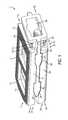
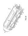
- FIG. 1is a perspective view of one aspect of an expandable inter-body fusion device that is expandable by moving an insert toward a leading end of the device, in a first unexpanded position;
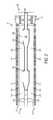
- FIG. 2is a side elevational view of the expandable inter-body fusion device of FIG. 1 , illustrating an aspect that is not substantially angled longitudinally, in the first unexpanded position;
- FIG. 3is a trailing end elevational view of the expandable inter-body fusion device FIG. 1 , illustrating an aspect that is angled transversely;
- FIG. 4is a perspective view of the insert of the expandable inter-body fusion device of FIG. 1 ;
- FIG. 5is a side elevational view of the insert of FIG. 4 ;
- FIG. 6is a bottom perspective view of a first plate of the expandable inter-body fusion device of FIG. 1 ;
- FIG. 7is a perspective view of the expandable inter-body fusion device of FIG. 1 in a second expanded position
- FIG. 8is a side elevational view of the expandable inter-body fusion device of FIG. 1 in the second expanded position
- FIG. 9is a perspective view of a threaded endcap for use with the expandable inter-body fusion device of FIG. 1 ;
- FIG. 10is a cutaway perspective view of the expandable inter-body fusion device of FIG. 1 in the second expanded position, cut substantially along the longitudinal axis and having the endcap of FIG. 9 ;
- FIG. 11is perspective view of an endcap having a single lead cam lock
- FIG. 12is a cutaway perspective view of an expandable inter-body fusion device in the second expanded position and having the endcap of FIG. 11 ;
- FIG. 13is a perspective view of one aspect of an expandable inter-body fusion device
- FIG. 14is a perspective view of an endcap coupled to a boss
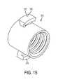
- FIG. 15is a perspective view of the boss of FIG. 14 ;
- FIG. 16is a perspective view of the endcap of FIG. 14 ;
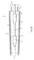
- FIG. 17is a cutaway perspective view of an expandable inter-body fusion device in the second expanded position having an endcap and boss as in FIG. 14 ;
- FIGS. 18A-18Iare a series of perspective views of an expandable inter-body fusion device used in a DLIF approach
- FIG. 19is a perspective view of one aspect of an expandable inter-body fusion device that is expanded by moving an insert toward the leading end of the device, in the first unexpanded position;
- FIG. 20is a side elevational view of the expandable inter-body fusion device of FIG. 19 , illustrating an aspect that is angled longitudinally, in the first unexpanded position;
- FIG. 21is a side elevational view of the expandable inter-body fusion device of FIG. 19 , illustrating the longitudinal angle;
- FIG. 22is a side elevational view of the expandable inter-body fusion device FIG. 19 , illustrating an aspect that is angled transversely;
- FIG. 23is a trailing end elevational view of the expandable inter-body fusion device FIG. 19 , illustrating the transverse angle;
- FIG. 24is a side elevational view of the expandable inter-body fusion device of FIG. 19 in the second expanded position
- FIGS. 25A-25Iare a series of perspective views of an expandable inter-body fusion device used in an anterior OLIF approach;
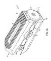
- FIG. 26is a perspective view of one aspect of an expandable inter-body fusion device that is expanded by moving an insert toward the trailing end of the device, in the first unexpanded position;
- FIG. 27is a side elevational view of the expandable inter-body fusion device of FIG. 26 ;
- FIG. 28is a trailing end elevational view of the expandable inter-body fusion device FIG. 26 ;
- FIG. 29is a perspective view of the insert of the expandable inter-body fusion device of FIG. 26 ;
- FIG. 30is a perspective view of the expandable inter-body fusion device of FIG. 26 in the second expanded position.
- FIGS. 31A-31Iare a series of perspective views of an expandable inter-body fusion device used in a posterior OLIF approach.
- Rangescan be expressed herein as from “about” one particular value, and/or to “about” another particular value. When such a range is expressed, another aspect includes from the one particular value and/or to the other particular value. Similarly, when values are expressed as approximations, by use of the antecedent “about,” it will be understood that the particular value forms another aspect. It will be further understood that the endpoints of each of the ranges are significant both in relation to the other endpoint, and independently of the other endpoint.
- the terms “optional” or “optionally”mean that the subsequently described event or circumstance may or may not occur, and that the description includes instances where said event or circumstance occurs and instances where it does not.
- relative termssuch as “substantially”, “generally”, “approximately”, and the like, are utilized herein to represent an inherent degree of uncertainty that may be attributed to any quantitative comparison, value, measurement, or other representation. These terms are also utilized herein to represent the degree by which a quantitative representation may vary from a stated reference without resulting in a change in the basic function of the subject matter at issue.
- an expandable inter-body fusion device 10 for use in spinal surgerysuch as, but not limited to, ALIF, OLIF, TLIF, LLIF, PLIF, and DLIF procedures.
- the expandable inter-body fusion device 10comprises a first plate 100 , a second plate 200 , and an insert 300 positioned substantially therebetween the first plate 100 and the second plate 200 .
- the first platehas a leading edge 102 , a trailing edge 104 , an upper bone contact surface 110 and an opposed first plate inner surface 120 .
- the second plate 200has a leading edge 202 , a trailing edge 204 , a lower bone contact surface 210 and an opposed second plate inner surface 220 .
- the first plate 100 , the second plate 200 , and the insert 300define an interior cavity 15 .
- the expandable inter-body fusion device 10has a leading end 17 and a trailing end 19 .
- moving the insert longitudinally with respect to the first and second platescan increase the distance between the first plate 100 relative to the second plate 200 , effectively expanding the inter-body fusion device and increasing the volume of the interior cavity 15 .
- At least one of the first plate 100 and the second plate 200has at least one longitudinal sidewall 130 , 230 extending substantially from the respective inner surface 120 , 220 .
- the at least one longitudinal sidewall 130 , 230comprises a plurality of longitudinal sidewalls.
- the longitudinal sidewallcan comprise two longitudinal sidewalls.
- the longitudinal sidewall(s)can be positioned substantially near a peripheral edge 140 , 240 of the first and/or second plate.
- the insert 300comprises a frame 310 with a plurality of longitudinal frame sides 320 .
- a longitudinal rail 330protrudes from the external surface of each of the longitudinal frame sides 320 .
- each longitudinal railcomprises at least one ramp 340 having at least one inclined surface 342 and at least one substantially flat surface 344 .
- each rampcan comprise an upper inclined surface 343 , a lower inclined surface 345 , an upper flat surface 347 and a lower flat surface 349 .
- each of the longitudinal rails 330has a first rail thickness that corresponds to the distance between the upper flat surface and the lower flat surface of the ramp 340 , and a second rail thickness in areas of the longitudinal rail that do not comprise the ramp.
- the second rail thicknesscan be less than the first rail thickness.
- each of the longitudinal rails 330comprises a plurality of ramps.
- each longitudinal railcan comprise a first ramp 340 spaced from a second ramp by a predetermined longitudinal distance along the longitudinal rail.
- each longitudinal sidewall 130 of the first plate 100can substantially align with a longitudinal sidewall 230 of the second plate 200 .
- each longitudinal sidewall of the first platecan substantially overlie at least a portion of a longitudinal sidewall of the second plate.
- Each set of substantially aligned longitudinal sidewalls(a longitudinal sidewall 130 from the first plate 100 and a longitudinal sidewall 230 from the second plate 200 ) define at least one void 150 , as illustrated in FIGS. 1 and 2 .
- the at least one voidcan be sized and shaped to complimentarily accept a ramp 340 of the insert 300 therein.
- in a first unexpanded positionas illustrated in FIG.
- each of the ramps of the insertcan be positioned substantially within the void 150 formed between the substantially aligned longitudinal sidewalls 130 , 230 of the first and second plates 100 , 200 .
- each longitudinal sidewall 130 , 230can be positioned substantially near or in contact with the respective longitudinal rail 330 of the insert 300 .
- the first unexpanded positionis the position in which the expandable inter-body fusion device 10 can be to be inserted between the adjacent vertebrae of a patient.
- the expandable inter-body fusion device 10can be selectively adjusted about and between the first unexpanded position, in which the ramps 340 of the insert 300 can be positioned substantially within the void 150 of the first and second plates 100 , 200 , and a second expanded position in which the ramps of the insert are not positioned substantially within the void.
- the flat surface 344 of the rampin the second expanded position, can engage the inner surface 120 of the longitudinal sidewall 130 of the first plate 100 and/or the inner surface 220 of the longitudinal sidewall 230 of the second plate 200 .
- the expandable inter-body fusion device 10in the second expanded position, can have a height and interior cavity 15 volume that is greater than the height and interior cavity volume of the expandable inter-body fusion device in the first, unexpanded position. That is, in the first unexpanded position, the interior cavity 15 of the device can have a first cavity size, and in the second expanded position the interior cavity has a second cavity size that is greater than the first cavity size.
- the insert 300can be moved longitudinally from a first insert position, in which the ramps 340 of the insert 300 can be positioned substantially within the void 150 of the first and second plates 100 , 200 , toward either the trailing end 19 or the leading end 17 of the device to a second insert position, thereby moving the ramps 340 into contact with a portion of at least one of the longitudinal sidewalls 130 , 230 .
- the aligned longitudinal sidewalls of the first and second plates 100 , 200are separate by traveling up the inclined surfaces 342 of the ramp until the first plate and the second plate are separated and supported by the flat surfaces 344 of the ramp.
- portions of the longitudinal sidewallsare supported by the load bearing properties of the flat surfaces of the ramps.
- the amount of separation achievable between the first plate and the second platecan be determined by the height of the ramp.
- the ramps 340can be double inclined, with two inclined surfaces 342 (upper inclined surface 343 and lower inclined surface 345 ) and two flat surfaces 344 (upper flat surface 347 and lower flat surface 349 ).
- each inclined surfacecan be configured to cam the longitudinal sidewall 130 , 230 of one of the first plate 100 or the second plate 200 and each flat surface 344 configured to support a portion of the respective longitudinal sidewall.
- the rampscan be single inclined, with only one inclined surface and one flat per ramp. In this aspect, the opposing surface would remain substantially adjacent and parallel to the respective longitudinal sidewall.
- the inclined surface 342leads the ramp 340 , as shown in FIGS. 1 and 2 . That is, the inclined surface of each ramp is positioned between the leading end 17 of the expandable inter-body fusion device 10 and the flat surface 344 of each ramp 340 . As such, moving the insert 300 longitudinally toward the leading end 17 of the device moves the device 10 from the first unexpanded position, to the second expanded position.
- the inclined surfacecan trail the ramp, as shown in FIG. 26 . That is, in this aspect, the inclined surface 342 of each ramp 340 can be positioned between the trailing end 19 of the expandable inter-body fusion device and the flat surface 344 of each ramp. Accordingly then, moving the insert 300 longitudinally toward the trailing end 19 of the expandable inter-body fusion device 10 can move the device into the second expanded position.
- the insert 300can have a first longitudinal tongue 350 extending from the external surface of each of the longitudinal frame sides 320 and a second longitudinal tongue 355 extending from the external surface of each of the longitudinal frame sides 320 .
- the first longitudinal tonguecan be spaced from the second longitudinal tongue a predetermined distance.
- the first longitudinal tongue 350can be positioned near or adjacent to an upper edge of the longitudinal frame sides, and the second longitudinal tongue 355 can be positioned near or adjacent to a lower edge of the longitudinal frame sides 320 .
- the first longitudinal tonguecan be substantially parallel to the second longitudinal tongue.
- the first the first longitudinal tongue 350can be at an angle relative to the second longitudinal tongue 355 .
- the first plate 100can define a groove, recess, or lip 160 in each longitudinal sidewall (as illustrated in FIG. 6 ) that is configured to mate with the first longitudinal tongue 350 of the insert 300 .
- the second plate 200can define a groove, recess, or lip 260 configured to mate with the second longitudinal tongue 355 of the insert.
- the first longitudinal tongue and the second longitudinal tonguecan be configured to move within the groove or recess to allow expansion of the device.
- at least one of the groove, recess, and lip 160 , 260 of the first and second plates 1000 , 200can engage the first longitudinal tongue 350 or the second longitudinal tongue 355 to retain the first and second plates to the insert 300 after expansion.
- the groove and tongue relationshipcan be reversed.
- this technologycan be used for a variety of implants used for a variety of spinal procedures. As mentioned before, these procedures include, but are not limited to OLIF, DLIF, PLIF, ALIF, TLIF, and LLIF. Because of this, depending upon the procedure and point of insertion for the implant, the geometry of the implant can differ. For example, in a DLIF expandable device, the approach is lateral. As such, the upper bone contact surface 110 can be transversely angled with respect to the lower bone contact surface 210 from a first sidewall to a second sidewall to match, increase, or decrease lordosis, as shown in FIGS. 3 and 23 .
- the expandable inter-body fusion device 10is not necessarily angled longitudinally from the leading end 17 of the device to the trailing end 19 of the 10 .
- the degree of transverse angle ⁇can vary from about 0 degrees to about 15 degrees. In another aspect, the transverse angle ⁇ can vary from about 4 degrees to about 12 degrees. In yet another aspect, the transverse angle ⁇ can vary from about 6 degrees to about 8 degrees.
- the expandable inter-body fusion device 10can expand in height a distance from about 1 mm to about 5 mm, depending on the original height of the device, the size of the void 150 of the first and second plates 100 , 200 and/or the height of the ramps 340 of the insert 300 . In this example, the insert 300 can expand the device symmetrically.
- the expandable inter-body fusion device 10can be inserted obliquely, either anteriorly or posteriorly.
- the upper bone contact surface 110can be angled transversely with respect to the lower bone contact surface 210 from the first sidewall to the second sidewall depending on the need to match, increase, or decrease lordosis.
- the upper bone contact surfacecan also be angled longitudinally with respect to the lower bone contact surface from the leading end 17 of the device to the trailing end 19 , as illustrated in FIG. 21 .
- a longitudinal angle ⁇ between the upper bone contact surface 110 and the lower bone contact surfacecan vary from about 0 degrees to about 15 degrees.
- the longitudinal angle ⁇can vary from about 4 degrees to about 12 degrees. In yet another aspect, the longitudinal angle ⁇ can vary from about 6 degrees to about 8 degrees.
- the combination of longitudinal angle ⁇ and transverse angle ⁇can vary depending about the angle of insertion. It would be desired to at least substantially fit the expandable inter-body fusion device 10 with the particular insertion approach angle so that the resulting combined angle is substantially posterior-anterior only or not at all.
- the upper bone contact surface 110can be angled with respect to the lower bone contact surface 210 in two planes, the device substantially ensures orthogonal lordosis.
- At least one of the first plate 100 and the second plate 200can define at least one graft window 170 , 270 that is in communication with the interior cavity 15 .
- the at least one graft window 170 defined in the first platecan overlie at least a portion of the at least one graft window 270 of the second plate, thereby permitting bone growth therethrough.
- the upper bone contact surface 110 of the first plate 100comprises ridges 112 for frictionally engaging a first vertebra of the patient.
- the lower bone contact surface 210 of the second platecan comprise ridges 212 to frictionally engage a second vertebra of the patient.
- the leading end 17 of the expandable inter-body fusion device 10can be tapered to facilitate insertion.
- a leading portion of the first plate 100 , the second plate 200 , and/or the insert 300can be tapered to facilitate insertion.
- the trailing end 19 of the insertcan define an aperture 360 in communication with the interior cavity 15 .
- the aperture 360can facilitate the passage of bone growth material, such as for example and not meant to be limiting, autograft or allograft bone product, or synthetic bone substitute, and the like. In this fashion, the interior cavity 15 can be packed with bone growth material after the expandable inter-body fusion device 10 has been expanded to the second expanded position.
- the devicecan also comprise an endcap 370 configured to engage the insert, as illustrated in FIG. 7 .
- the endcapcan be used to maintain the device in the second expanded position.
- the endcapcan be sized and shaped so that a portion of the endcap 370 , such as a flange and the like, can extend past the peripheral edge of the aperture 360 of the insert 300 . In this aspect, when the endcap is engaged with the insert, the endcap 370 can prevent the insert 300 from moving back toward the leading end of the device.
- portions of the trailing end of the devicesuch as portions of the first plate 100 , the second plate 200 and/or the insert 300 can be threaded to facilitate the complimentary threading of the endcap.
- the threaded trailing end of the device 10can also be used to engage the distal end of the insertion tool (not shown) and permit the movement of the insert with respect to the first and second plates.
- a leading end of the insertcan comprise a tapered nose 390 , as shown in FIG. 27 .
- the devicecan further comprise a structure to facilitate securing the insert to a portion of the first plate 100 and/or the second plate 200 , or to an adjacent vertebra of the patient.
- the endcap 370comprises a lock 376 configured to matingly engage a portion of the first and second plates 100 , 200 .
- the lockcomprises at least one lead 375 .
- the lockcan be a single or dual lead cam lock.
- the leadscan be tapered or square ended.
- the endcapcan be inserted through the aperture 360 defined in the trailing end 19 of the device and into the interior cavity 15 with the leads rotated to a first orientation in which the leads 375 do not engage the device (as illustrated in FIG. 13 ).
- the endcapcan be rotated to a second orientation in which the leads engage a portion of at least one of the first and second plates 100 , 200 .
- the endcapcan further comprise a boss 378 having a lock 376 .
- the lockcomprises at least one lead 375 .
- the lockcan be a single or dual lead cam lock.
- the bosscan define internal threads that are complimentarily sized to engage external threads positioned on a portion of the endcap 370 .
- the lock 376 of the bosscan be configured to engage a portion of the first and second plates 100 , 200 , and the end cap can engage the boss.
- either the endcap itself or a separate bosscan comprise radially extending blades (not shown) that, when rotated, are configured to engage the adjacent bony structure to retain the expandable inter-body device in the desired position. It is also contemplated that the inner surface 120 , 220 of the first and second plates can have a threaded portion to engage an endcap 370 having external threads.
- the expandable inter-body fusion device 10can be longitudinally cannulated. This aspect enables the device to be inserted over a guide wire. As one skilled in the art can appreciate, in an exemplified aspect, the insertion tool would necessarily have to be cannulated.
- the methodcomprises accessing the desired disc space, choosing the correct expandable inter-body fusion device size with the appropriate height and angle, inserting the expandable inter-body fusion device 10 into the desired area in the disc space, expanding the expandable inter-body fusion device from the first unexpanded position to the second expanded position with longitudinal movement of the insert 300 , and securing the insert to the first and second plates 100 , 200 .
- An additional step of packing the interior cavity 15 via the aperture 360 in the trailing end 19 of the expandable inter-body fusion device with bone fusion material either prior to or after expansionis also contemplated.
- the step of securing the insert to the first and second platescan be replaced by securing the expandable inter-body fusion device 10 to the surrounding bony structure.
- the step of expanding the inter-body fusion devicecomprises the step of moving the insert 300 with respect to the first and second plates 100 , 200 toward the trailing end 19 of the expandable inter-body fusion device.
- the step of expanding the expandable inter-body fusion device 10comprises the step of moving the insert with respect to the first and second plates toward the leading end 17 of the expandable inter-body fusion device.
- the step of choosing the correct expandable inter-body fusion device 10 size with the appropriate height and anglecomprises placing an undersized trial device in the disc space, expanding the trial device to the second expanded position, and repeating until the correct height and lordosis is found.
- the trial height and anglegives the information to prescribe the correct expandable inter-body fusion device for the procedure.
Landscapes
- Health & Medical Sciences (AREA)
- Biomedical Technology (AREA)
- Engineering & Computer Science (AREA)
- Orthopedic Medicine & Surgery (AREA)
- Transplantation (AREA)
- Neurology (AREA)
- Vascular Medicine (AREA)
- Heart & Thoracic Surgery (AREA)
- Oral & Maxillofacial Surgery (AREA)
- Life Sciences & Earth Sciences (AREA)
- Animal Behavior & Ethology (AREA)
- General Health & Medical Sciences (AREA)
- Public Health (AREA)
- Veterinary Medicine (AREA)
- Cardiology (AREA)
- Physical Education & Sports Medicine (AREA)
- Prostheses (AREA)
- Surgical Instruments (AREA)
- Lining Or Joining Of Plastics Or The Like (AREA)
Abstract
Description
Claims (19)
Priority Applications (3)
| Application Number | Priority Date | Filing Date | Title |
|---|---|---|---|
| US14/216,996US9987143B2 (en) | 2013-03-15 | 2014-03-17 | Expandable inter-body fusion devices and methods |
| US15/978,664US11051951B2 (en) | 2013-03-15 | 2018-05-14 | Expandable inter-body fusion devices and methods |
| US17/315,694US20210259849A1 (en) | 2013-03-15 | 2021-05-10 | Expandable inter-body fusion devices and methods |
Applications Claiming Priority (2)
| Application Number | Priority Date | Filing Date | Title |
|---|---|---|---|
| US201361786612P | 2013-03-15 | 2013-03-15 | |
| US14/216,996US9987143B2 (en) | 2013-03-15 | 2014-03-17 | Expandable inter-body fusion devices and methods |
Related Child Applications (1)
| Application Number | Title | Priority Date | Filing Date |
|---|---|---|---|
| US15/978,664ContinuationUS11051951B2 (en) | 2013-03-15 | 2018-05-14 | Expandable inter-body fusion devices and methods |
Publications (2)
| Publication Number | Publication Date |
|---|---|
| US20140277474A1 US20140277474A1 (en) | 2014-09-18 |
| US9987143B2true US9987143B2 (en) | 2018-06-05 |
Family
ID=51531310
Family Applications (4)
| Application Number | Title | Priority Date | Filing Date |
|---|---|---|---|
| US14/216,996ActiveUS9987143B2 (en) | 2013-03-15 | 2014-03-17 | Expandable inter-body fusion devices and methods |
| US14/777,494Active2035-03-17US10369010B2 (en) | 2013-03-15 | 2014-03-17 | Expandable inter-body fusion devices and methods |
| US15/978,664ActiveUS11051951B2 (en) | 2013-03-15 | 2018-05-14 | Expandable inter-body fusion devices and methods |
| US17/315,694AbandonedUS20210259849A1 (en) | 2013-03-15 | 2021-05-10 | Expandable inter-body fusion devices and methods |
Family Applications After (3)
| Application Number | Title | Priority Date | Filing Date |
|---|---|---|---|
| US14/777,494Active2035-03-17US10369010B2 (en) | 2013-03-15 | 2014-03-17 | Expandable inter-body fusion devices and methods |
| US15/978,664ActiveUS11051951B2 (en) | 2013-03-15 | 2018-05-14 | Expandable inter-body fusion devices and methods |
| US17/315,694AbandonedUS20210259849A1 (en) | 2013-03-15 | 2021-05-10 | Expandable inter-body fusion devices and methods |
Country Status (2)
| Country | Link |
|---|---|
| US (4) | US9987143B2 (en) |
| WO (2) | WO2014145939A2 (en) |
Cited By (54)
| Publication number | Priority date | Publication date | Assignee | Title |
|---|---|---|---|---|
| US20150025635A1 (en)* | 2013-07-17 | 2015-01-22 | Aesculap Implant Systems, Llc | Spinal interbody device, system and method |
| US10285824B2 (en) | 2014-10-28 | 2019-05-14 | Spectrum Spine Ip Holdings, Llc | Expandable, adjustable inter-body fusion devices and methods |
| US10322014B2 (en) | 2013-09-09 | 2019-06-18 | Integrity Implants Inc. | Expandable trial with telescopic stabilizers |
| US10383743B2 (en) | 2016-09-21 | 2019-08-20 | Integrity Implants Inc. | Laterovertically-expanding fusion cage systems |
| US10507116B2 (en) | 2017-01-10 | 2019-12-17 | Integrity Implants Inc. | Expandable intervertebral fusion device |
| US10709578B2 (en) | 2017-08-25 | 2020-07-14 | Integrity Implants Inc. | Surgical biologics delivery system and related methods |
| US10758368B2 (en) | 2015-01-20 | 2020-09-01 | Integrity Implants Inc. | Stabilized, 4 beam intervertebral scaffolding system |
| US10786366B2 (en) | 2012-12-13 | 2020-09-29 | Integrity Implants Inc. | Angled, rigid intervertebral scaffolding |
| US10888431B1 (en) | 2014-10-28 | 2021-01-12 | Spectrum Spine Ip Holdings, Llc | Expandable, adjustable inter-body fusion devices and methods |
| US11013610B2 (en)* | 2017-10-18 | 2021-05-25 | Spine Wave, Inc. | Expandable anterior lumbar interbody fusion device |
| US11051951B2 (en) | 2013-03-15 | 2021-07-06 | Spectrum Spine Ip Holdings, Llc | Expandable inter-body fusion devices and methods |
| US11224522B2 (en) | 2017-07-24 | 2022-01-18 | Integrity Implants Inc. | Surgical implant and related methods |
| US20220015920A1 (en)* | 2018-11-19 | 2022-01-20 | Axis Spine Technologies Ltd | Intervertebral devices |
| US11234829B2 (en)* | 2019-01-21 | 2022-02-01 | Degen Medical, Inc. | Expandable intervertebral spacers |
| US11285014B1 (en) | 2020-11-05 | 2022-03-29 | Warsaw Orthopedic, Inc. | Expandable inter-body device, system, and method |
| US11285018B2 (en) | 2018-03-01 | 2022-03-29 | Integrity Implants Inc. | Expandable fusion device with independent expansion systems |
| US11291554B1 (en) | 2021-05-03 | 2022-04-05 | Medtronic, Inc. | Unibody dual expanding interbody implant |
| US11376134B1 (en) | 2020-11-05 | 2022-07-05 | Warsaw Orthopedic, Inc. | Dual expanding spinal implant, system, and method of use |
| US11395743B1 (en) | 2021-05-04 | 2022-07-26 | Warsaw Orthopedic, Inc. | Externally driven expandable interbody and related methods |
| US11517443B2 (en) | 2020-11-05 | 2022-12-06 | Warsaw Orthopedic, Inc. | Dual wedge expandable implant, system and method of use |
| US11554020B2 (en) | 2020-09-08 | 2023-01-17 | Life Spine, Inc. | Expandable implant with pivoting control assembly |
| US11564724B2 (en) | 2020-11-05 | 2023-01-31 | Warsaw Orthopedic, Inc. | Expandable inter-body device, system and method |
| US11602439B2 (en) | 2020-04-16 | 2023-03-14 | Life Spine, Inc. | Expandable implant assembly |
| US11602440B2 (en) | 2020-06-25 | 2023-03-14 | Life Spine, Inc. | Expandable implant assembly |
| US11612499B2 (en) | 2021-06-24 | 2023-03-28 | Warsaw Orthopedic, Inc. | Expandable interbody implant |
| US11638653B2 (en) | 2020-11-05 | 2023-05-02 | Warsaw Orthopedic, Inc. | Surgery instruments with a movable handle |
| US11730608B2 (en) | 2021-07-13 | 2023-08-22 | Warsaw Orthopedic, Inc. | Monoblock expandable interbody implant |
| US11806245B2 (en) | 2020-03-06 | 2023-11-07 | Eit Emerging Implant Technologies Gmbh | Expandable intervertebral implant |
| US11806250B2 (en) | 2018-02-22 | 2023-11-07 | Warsaw Orthopedic, Inc. | Expandable spinal implant system and method of using same |
| US11833059B2 (en) | 2020-11-05 | 2023-12-05 | Warsaw Orthopedic, Inc. | Expandable inter-body device, expandable plate system, and associated methods |
| US11850160B2 (en) | 2021-03-26 | 2023-12-26 | Medos International Sarl | Expandable lordotic intervertebral fusion cage |
| US11850163B2 (en) | 2022-02-01 | 2023-12-26 | Warsaw Orthopedic, Inc. | Interbody implant with adjusting shims |
| US11857432B2 (en) | 2020-04-13 | 2024-01-02 | Life Spine, Inc. | Expandable implant assembly |
| US11896494B2 (en) | 2017-07-10 | 2024-02-13 | Life Spine, Inc. | Expandable implant assembly |
| US11963881B2 (en) | 2020-11-05 | 2024-04-23 | Warsaw Orthopedic, Inc. | Expandable inter-body device, system, and method |
| US11986398B2 (en) | 2013-03-13 | 2024-05-21 | Life Spine, Inc. | Expandable implant assembly |
| US12023258B2 (en) | 2021-04-06 | 2024-07-02 | Medos International Sarl | Expandable intervertebral fusion cage |
| US12042395B2 (en) | 2019-06-11 | 2024-07-23 | Life Spine, Inc. | Expandable implant assembly |
| US12090064B2 (en) | 2022-03-01 | 2024-09-17 | Medos International Sarl | Stabilization members for expandable intervertebral implants, and related systems and methods |
| US12097124B2 (en) | 2009-03-30 | 2024-09-24 | DePuy Synthes Products, Inc. | Zero profile spinal fusion cage |
| US12121453B2 (en) | 2020-11-05 | 2024-10-22 | Warsaw Orthopedic, Inc. | Dual wedge expandable implant with eyelets, system, and method of use |
| US12138179B2 (en) | 2019-06-10 | 2024-11-12 | Life Spine, Inc. | Expandable implant assembly with compression features |
| US12171439B2 (en) | 2020-11-05 | 2024-12-24 | Warsaw Orthopedic, Inc. | Protected drill |
| US12193948B2 (en) | 2013-03-13 | 2025-01-14 | Life Spine, Inc. | Expandable implant assembly |
| US12239544B2 (en) | 2020-11-05 | 2025-03-04 | Warsaw Orthopedic, Inc. | Rhomboid shaped implants |
| US12268614B2 (en) | 2021-06-24 | 2025-04-08 | Warsaw Orthopedic, Inc. | Interbody implant with adjusting shims |
| US12295865B2 (en) | 2021-06-24 | 2025-05-13 | Warsaw Orthopedic, Inc. | Expandable interbody implant and corresponding inserter |
| US12318308B2 (en) | 2020-11-05 | 2025-06-03 | Warsaw Orthopedic, Inc. | Dual expandable inter-body device |
| US12329652B2 (en) | 2020-07-20 | 2025-06-17 | Integrity Implants Inc. | Expandable fusion device with independent expansion systems |
| US12336917B2 (en) | 2020-05-15 | 2025-06-24 | Life Spine, Inc. | Steerable implant assembly |
| US12414863B2 (en) | 2021-06-24 | 2025-09-16 | Warsaw Orthopedic, Inc. | Expandable interbody implant and corresponding surgical tool |
| US12427031B2 (en) | 2017-05-08 | 2025-09-30 | Medos International Sarl | Expandable cage |
| US12433757B2 (en) | 2016-06-28 | 2025-10-07 | Eit Emerging Implant Technologies Gmbh | Expandable, angularly adjustable and articulating intervertebral cages |
| US12440349B2 (en) | 2022-02-04 | 2025-10-14 | Warsaw Orthopedic, Inc. | Expandable interbody implant and breakoff screw |
Families Citing this family (36)
| Publication number | Priority date | Publication date | Assignee | Title |
|---|---|---|---|---|
| US6793678B2 (en) | 2002-06-27 | 2004-09-21 | Depuy Acromed, Inc. | Prosthetic intervertebral motion disc having dampening |
| WO2008070863A2 (en) | 2006-12-07 | 2008-06-12 | Interventional Spine, Inc. | Intervertebral implant |
| US8900307B2 (en) | 2007-06-26 | 2014-12-02 | DePuy Synthes Products, LLC | Highly lordosed fusion cage |
| EP2237748B1 (en) | 2008-01-17 | 2012-09-05 | Synthes GmbH | An expandable intervertebral implant |
| US8936641B2 (en) | 2008-04-05 | 2015-01-20 | DePuy Synthes Products, LLC | Expandable intervertebral implant |
| KR101687435B1 (en) | 2009-07-06 | 2016-12-19 | 신세스 게엠바하 | Expandable fixation assemblies |
| EP2547292B1 (en) | 2010-03-16 | 2019-04-24 | Pinnacle Spine Group, LLC | Ntervertebral implants and graft delivery systems |
| US8979860B2 (en) | 2010-06-24 | 2015-03-17 | DePuy Synthes Products. LLC | Enhanced cage insertion device |
| US8623091B2 (en) | 2010-06-29 | 2014-01-07 | DePuy Synthes Products, LLC | Distractible intervertebral implant |
| US20120078372A1 (en) | 2010-09-23 | 2012-03-29 | Thomas Gamache | Novel implant inserter having a laterally-extending dovetail engagement feature |
| US9248028B2 (en) | 2011-09-16 | 2016-02-02 | DePuy Synthes Products, Inc. | Removable, bone-securing cover plate for intervertebral fusion cage |
| US9380932B1 (en) | 2011-11-02 | 2016-07-05 | Pinnacle Spine Group, Llc | Retractor devices for minimally invasive access to the spine |
| EP2877127B1 (en) | 2012-07-26 | 2019-08-21 | Synthes GmbH | Expandable implant |
| US9717601B2 (en) | 2013-02-28 | 2017-08-01 | DePuy Synthes Products, Inc. | Expandable intervertebral implant, system, kit and method |
| US9522070B2 (en) | 2013-03-07 | 2016-12-20 | Interventional Spine, Inc. | Intervertebral implant |
| WO2014159739A1 (en) | 2013-03-14 | 2014-10-02 | Pinnacle Spine Group, Llc | Interbody implants and graft delivery systems |
| US9364341B2 (en)* | 2014-01-09 | 2016-06-14 | Warsaw Orthopedic, Inc. | Spinal implant system and method |
| US11426290B2 (en) | 2015-03-06 | 2022-08-30 | DePuy Synthes Products, Inc. | Expandable intervertebral implant, system, kit and method |
| US9913727B2 (en) | 2015-07-02 | 2018-03-13 | Medos International Sarl | Expandable implant |
| US10137009B2 (en)* | 2015-09-02 | 2018-11-27 | Globus Medical, Inc. | Expandable intervertebral fusion devices and methods of installation thereof |
| US11510788B2 (en) | 2016-06-28 | 2022-11-29 | Eit Emerging Implant Technologies Gmbh | Expandable, angularly adjustable intervertebral cages |
| US9974662B2 (en)* | 2016-06-29 | 2018-05-22 | Globus Medical, Inc. | Expandable fusion device and method of installation thereof |
| US10052215B2 (en)* | 2016-06-29 | 2018-08-21 | Globus Medical, Inc. | Expandable fusion device and method of installation thereof |
| US10258483B2 (en) | 2016-08-19 | 2019-04-16 | Degen Medical, Inc. | Laminate implantable medical devices |
| US11033394B2 (en) | 2016-10-25 | 2021-06-15 | Institute for Musculoskeletal Science and Education, Ltd. | Implant with multi-layer bone interfacing lattice |
| US10537436B2 (en) | 2016-11-01 | 2020-01-21 | DePuy Synthes Products, Inc. | Curved expandable cage |
| US10888433B2 (en) | 2016-12-14 | 2021-01-12 | DePuy Synthes Products, Inc. | Intervertebral implant inserter and related methods |
| US11344424B2 (en) | 2017-06-14 | 2022-05-31 | Medos International Sarl | Expandable intervertebral implant and related methods |
| US10940016B2 (en) | 2017-07-05 | 2021-03-09 | Medos International Sarl | Expandable intervertebral fusion cage |
| US11801144B2 (en) | 2017-09-14 | 2023-10-31 | Degen Medical, Inc. | Methods of making medical devices |
| US11446156B2 (en) | 2018-10-25 | 2022-09-20 | Medos International Sarl | Expandable intervertebral implant, inserter instrument, and related methods |
| US11123198B2 (en) | 2018-11-13 | 2021-09-21 | Degen Medical, Inc. | Expandable spacers |
| US11253372B2 (en)* | 2019-03-09 | 2022-02-22 | Iorthopedics, Inc. | Universally expanding cages |
| US11547575B2 (en) | 2019-09-27 | 2023-01-10 | Degen Medical, Inc. | Expandable intervertebral spacers |
| EP4312890A1 (en) | 2021-04-02 | 2024-02-07 | Nuvasive, Inc. | Expansion driver |
| JP2024514536A (en) | 2021-04-04 | 2024-04-02 | ニューヴェイジヴ,インコーポレイテッド | expandable implant |
Citations (33)
| Publication number | Priority date | Publication date | Assignee | Title |
|---|---|---|---|---|
| US5683394A (en)* | 1995-09-29 | 1997-11-04 | Advanced Spine Fixation Systems, Inc. | Fusion mass constrainer |
| US20040087947A1 (en)* | 2002-08-28 | 2004-05-06 | Roy Lim | Minimally invasive expanding spacer and method |
| US6896677B1 (en)* | 2003-12-11 | 2005-05-24 | A-Spine Holding Group Corp. | Rotary device for retrieving spinal column under treatment |
| US20060122701A1 (en)* | 2004-11-23 | 2006-06-08 | Kiester P D | Posterior lumbar interbody fusion expandable cage with lordosis and method of deploying the same |
| US20060129244A1 (en)* | 2004-10-25 | 2006-06-15 | Alphaspine, Inc. | Expandable intervertebral spacer method and apparatus |
| US20080234687A1 (en)* | 2005-08-16 | 2008-09-25 | Laurent Schaller | Devices for treating the spine |
| US7722674B1 (en)* | 2005-08-12 | 2010-05-25 | Innvotec Surgical Inc. | Linearly expanding spine cage for enhanced spinal fusion |
| US20100204795A1 (en)* | 2008-11-12 | 2010-08-12 | Stout Medical Group, L.P. | Fixation device and method |
| US20100292796A1 (en)* | 2009-05-14 | 2010-11-18 | Stout Medical Group, L.P. | Expandable support device and method of use |
| US20110307065A1 (en) | 2007-11-30 | 2011-12-15 | Ching-Kong CHAO | Adjustable vertebral spacer for vertebral reconstruction |
| US20110319997A1 (en)* | 2010-06-25 | 2011-12-29 | Chad Glerum | Expandable Fusion Device and Method of Installation Thereof |
| US20120029637A1 (en) | 2010-08-02 | 2012-02-02 | Ragab Ashraf A | Rotatable Cam Lift for an Expandable Bone Cage |
| US20120059470A1 (en)* | 2010-09-03 | 2012-03-08 | Mark Weiman | Expandable Fusion Device and Method of Installation Thereof |
| US20120071978A1 (en)* | 2010-06-29 | 2012-03-22 | Jann-Paul Suedkamp | Distractible intervertebral implant |
| US20120226357A1 (en) | 2010-01-11 | 2012-09-06 | Innova Spinal Technologies, Llc | Expandable intervertebral implant and associated surgical method |
| US20120232552A1 (en) | 2011-03-10 | 2012-09-13 | Interventional Spine, Inc. | Method and apparatus for minimally invasive insertion of intervertebral implants |
| US8292958B1 (en)* | 2007-07-02 | 2012-10-23 | Theken Spine, Llc | Spinal cage having deployable member |
| US20120310349A1 (en) | 2003-08-05 | 2012-12-06 | Flexuspine, Inc. | Expandable articulating intervertebral implant with limited articulation |
| US20130023994A1 (en) | 2009-10-15 | 2013-01-24 | Chad Glerum | Expandable Fusion Device and Method of Installation Thereof |
| US8398713B2 (en)* | 2010-09-03 | 2013-03-19 | Globus Medical, Inc. | Expandable fusion device and method of installation thereof |
| US20130085572A1 (en)* | 2011-09-30 | 2013-04-04 | Chad Glerum | Expandable Fusion Device and Method of Installation Thereof |
| US20130103153A1 (en)* | 2011-10-24 | 2013-04-25 | Warsaw Orthopedic, Inc. | Interbody implant system and methods of use |
| US20130144388A1 (en)* | 2010-05-28 | 2013-06-06 | Benvenue Medical, Inc. | Disc Space Sizing Devices And Methods Of Using The Same |
| US20130158667A1 (en)* | 2011-11-17 | 2013-06-20 | Exactech, Inc. | Expandable interbody device system and method |
| US20130158664A1 (en)* | 2011-12-19 | 2013-06-20 | Warsaw Orthopedic, Inc. | Expandable interbody implant and methods of use |
| US20130158663A1 (en)* | 2011-12-19 | 2013-06-20 | Warsaw Orthopedic, Inc | Expandable interbody implant and methods of use |
| US8888854B2 (en)* | 2009-10-15 | 2014-11-18 | Globus Medical, Inc. | Expandable fusion device and method of installation thereof |
| US8888853B2 (en)* | 2009-10-15 | 2014-11-18 | Globus Medical Inc. | Expandable fusion device and method of installation thereof |
| US8894711B2 (en)* | 2010-01-11 | 2014-11-25 | Innova Spinal Technologies, Llc | Expandable intervertebral implant and associated surgical method |
| US20150012098A1 (en)* | 2013-07-03 | 2015-01-08 | Spine Innovation, Inc. | Methods and apparatus for implanting an interbody device |
| US20150012097A1 (en)* | 2013-07-03 | 2015-01-08 | Spinefrontier Inc | System amd method for an expandable intervertebral implant |
| US20150073553A1 (en)* | 2007-05-31 | 2015-03-12 | Spine Wave, Inc. | Expandable interbody fusion device |
| US20150112438A1 (en)* | 2013-10-18 | 2015-04-23 | Spine Wave, Inc. | Method of expanding an intradiscal space and providing an osteoconductive path during expansion |
Family Cites Families (46)
| Publication number | Priority date | Publication date | Assignee | Title |
|---|---|---|---|---|
| US5800550A (en) | 1996-03-13 | 1998-09-01 | Sertich; Mario M. | Interbody fusion cage |
| US6039761A (en) | 1997-02-12 | 2000-03-21 | Li Medical Technologies, Inc. | Intervertebral spacer and tool and method for emplacement thereof |
| US6641614B1 (en) | 1997-05-01 | 2003-11-04 | Spinal Concepts, Inc. | Multi-variable-height fusion device |
| DE19807236C2 (en) | 1998-02-20 | 2000-06-21 | Biedermann Motech Gmbh | Intervertebral implant |
| US6723126B1 (en) | 2002-11-01 | 2004-04-20 | Sdgi Holdings, Inc. | Laterally expandable cage |
| WO2004047689A1 (en) | 2002-11-21 | 2004-06-10 | Sdgi Holdings, Inc. | Systems and techniques for intravertebral spinal stablization with expandable devices |
| US7217291B2 (en) | 2003-12-08 | 2007-05-15 | St. Francis Medical Technologies, Inc. | System and method for replacing degenerated spinal disks |
| US7850733B2 (en) | 2004-02-10 | 2010-12-14 | Atlas Spine, Inc. | PLIF opposing wedge ramp |
| US20060095136A1 (en) | 2004-11-03 | 2006-05-04 | Mcluen Design, Inc. | Bone fusion device |
| USD524443S1 (en) | 2005-11-04 | 2006-07-04 | Quantum Orthopedics, Inc. | Interbody fusion device |
| EP1925272B1 (en) | 2006-11-23 | 2010-01-13 | BIEDERMANN MOTECH GmbH | Expandable intervertebral implant |
| WO2008070863A2 (en) | 2006-12-07 | 2008-06-12 | Interventional Spine, Inc. | Intervertebral implant |
| US8267939B2 (en) | 2008-02-28 | 2012-09-18 | Stryker Spine | Tool for implanting expandable intervertebral implant |
| US8216316B2 (en) | 2008-12-17 | 2012-07-10 | X-Spine Systems, Inc. | Prosthetic implant with biplanar angulation and compound angles |
| US8062375B2 (en) | 2009-10-15 | 2011-11-22 | Globus Medical, Inc. | Expandable fusion device and method of installation thereof |
| US9216095B2 (en) | 2009-10-15 | 2015-12-22 | Globus Medical, Inc. | Expandable fusion device and method of installation thereof |
| EP2547292B1 (en) | 2010-03-16 | 2019-04-24 | Pinnacle Spine Group, LLC | Ntervertebral implants and graft delivery systems |
| US8535380B2 (en) | 2010-05-13 | 2013-09-17 | Stout Medical Group, L.P. | Fixation device and method |
| US20120121774A1 (en) | 2010-07-30 | 2012-05-17 | James Marjeram | System and method for coating bulk articles |
| US8852279B2 (en) | 2010-09-03 | 2014-10-07 | Globus Medical, Inc. | Expandable fusion device and method of installation thereof |
| EP2723276B1 (en)* | 2011-06-17 | 2017-08-09 | Globus Medical, Inc. | Expandable spinal implant and flexible driver |
| US9358123B2 (en) | 2011-08-09 | 2016-06-07 | Neuropro Spinal Jaxx, Inc. | Bone fusion device, apparatus and method |
| EP2729092B1 (en) | 2011-08-16 | 2016-09-21 | Stryker European Holdings I, LLC | Expandable implant |
| US8845728B1 (en) | 2011-09-23 | 2014-09-30 | Samy Abdou | Spinal fixation devices and methods of use |
| US10159583B2 (en) | 2012-04-13 | 2018-12-25 | Neuropro Technologies, Inc. | Bone fusion device |
| US9532883B2 (en) | 2012-04-13 | 2017-01-03 | Neuropro Technologies, Inc. | Bone fusion device |
| EP2838452B1 (en) | 2012-04-16 | 2019-05-08 | BioSpine, LLC | Multiple spindle adjustable interbody fusion devices |
| US9839527B2 (en) | 2012-10-24 | 2017-12-12 | Spectrum Spine Ip Holdings, Llc | Expandable inter-body fusion devices and methods |
| US9492288B2 (en) | 2013-02-20 | 2016-11-15 | Flexuspine, Inc. | Expandable fusion device for positioning between adjacent vertebral bodies |
| US9522070B2 (en) | 2013-03-07 | 2016-12-20 | Interventional Spine, Inc. | Intervertebral implant |
| US10154911B2 (en) | 2013-03-13 | 2018-12-18 | Life Spine, Inc. | Expandable implant assembly |
| US9987143B2 (en) | 2013-03-15 | 2018-06-05 | Spectrum Spine Ip Holdings, Llc | Expandable inter-body fusion devices and methods |
| CA2906531C (en) | 2013-03-15 | 2020-10-06 | Neuropro Technologies, Inc. | Bodiless bone fusion device, apparatus and method |
| US20140296984A1 (en) | 2013-04-01 | 2014-10-02 | Mohammad Etminan | Cage system |
| US9668876B2 (en) | 2013-12-05 | 2017-06-06 | Spinal Elements, Inc. | Expandable interbody device |
| US9839528B2 (en) | 2014-02-07 | 2017-12-12 | Globus Medical, Inc. | Variable lordosis spacer and related methods of use |
| US8940049B1 (en) | 2014-04-01 | 2015-01-27 | Ex Technology, Llc | Expandable intervertebral cage |
| US9486328B2 (en) | 2014-04-01 | 2016-11-08 | Ex Technology, Llc | Expandable intervertebral cage |
| WO2016069796A1 (en) | 2014-10-28 | 2016-05-06 | Spectrum Spine Ip Holdings, Llc | Expandable, adjustable inter-body fusion devices and methods |
| US9937053B2 (en) | 2014-11-04 | 2018-04-10 | Warsaw Orthopedic, Inc. | Expandable interbody implant |
| US10363142B2 (en) | 2014-12-11 | 2019-07-30 | K2M, Inc. | Expandable spinal implants |
| US9713536B2 (en) | 2015-08-12 | 2017-07-25 | Warsaw Orthopedic, Inc. | Expandable spinal implant and method of implanting same |
| US10610376B2 (en) | 2015-10-16 | 2020-04-07 | Warsaw Orthopedic, Inc. | Expandable spinal implant system and method |
| US10219914B2 (en) | 2015-11-10 | 2019-03-05 | Globus Medical, Inc. | Stabilized expandable intervertebral spacer |
| US10111760B2 (en) | 2017-01-18 | 2018-10-30 | Neuropro Technologies, Inc. | Bone fusion system, device and method including a measuring mechanism |
| US10398563B2 (en) | 2017-05-08 | 2019-09-03 | Medos International Sarl | Expandable cage |
- 2014
- 2014-03-17USUS14/216,996patent/US9987143B2/enactiveActive
- 2014-03-17WOPCT/US2014/030796patent/WO2014145939A2/enactiveApplication Filing
- 2014-03-17USUS14/777,494patent/US10369010B2/enactiveActive
- 2014-03-17WOPCT/US2014/030862patent/WO2014145995A2/enactiveApplication Filing
- 2018
- 2018-05-14USUS15/978,664patent/US11051951B2/enactiveActive
- 2021
- 2021-05-10USUS17/315,694patent/US20210259849A1/ennot_activeAbandoned
Patent Citations (36)
| Publication number | Priority date | Publication date | Assignee | Title |
|---|---|---|---|---|
| US5683394A (en)* | 1995-09-29 | 1997-11-04 | Advanced Spine Fixation Systems, Inc. | Fusion mass constrainer |
| US20040087947A1 (en)* | 2002-08-28 | 2004-05-06 | Roy Lim | Minimally invasive expanding spacer and method |
| US20120310349A1 (en) | 2003-08-05 | 2012-12-06 | Flexuspine, Inc. | Expandable articulating intervertebral implant with limited articulation |
| US6896677B1 (en)* | 2003-12-11 | 2005-05-24 | A-Spine Holding Group Corp. | Rotary device for retrieving spinal column under treatment |
| US20060129244A1 (en)* | 2004-10-25 | 2006-06-15 | Alphaspine, Inc. | Expandable intervertebral spacer method and apparatus |
| US20060122701A1 (en)* | 2004-11-23 | 2006-06-08 | Kiester P D | Posterior lumbar interbody fusion expandable cage with lordosis and method of deploying the same |
| US7722674B1 (en)* | 2005-08-12 | 2010-05-25 | Innvotec Surgical Inc. | Linearly expanding spine cage for enhanced spinal fusion |
| US20080234687A1 (en)* | 2005-08-16 | 2008-09-25 | Laurent Schaller | Devices for treating the spine |
| US20150073553A1 (en)* | 2007-05-31 | 2015-03-12 | Spine Wave, Inc. | Expandable interbody fusion device |
| US8292958B1 (en)* | 2007-07-02 | 2012-10-23 | Theken Spine, Llc | Spinal cage having deployable member |
| US20110307065A1 (en) | 2007-11-30 | 2011-12-15 | Ching-Kong CHAO | Adjustable vertebral spacer for vertebral reconstruction |
| US20100204795A1 (en)* | 2008-11-12 | 2010-08-12 | Stout Medical Group, L.P. | Fixation device and method |
| US20100292796A1 (en)* | 2009-05-14 | 2010-11-18 | Stout Medical Group, L.P. | Expandable support device and method of use |
| US20130023994A1 (en) | 2009-10-15 | 2013-01-24 | Chad Glerum | Expandable Fusion Device and Method of Installation Thereof |
| US8888854B2 (en)* | 2009-10-15 | 2014-11-18 | Globus Medical, Inc. | Expandable fusion device and method of installation thereof |
| US8926704B2 (en)* | 2009-10-15 | 2015-01-06 | Globus Medical, Inc. | Expandable fusion device and method of installation thereof |
| US8888853B2 (en)* | 2009-10-15 | 2014-11-18 | Globus Medical Inc. | Expandable fusion device and method of installation thereof |
| US20120226357A1 (en) | 2010-01-11 | 2012-09-06 | Innova Spinal Technologies, Llc | Expandable intervertebral implant and associated surgical method |
| US8894712B2 (en)* | 2010-01-11 | 2014-11-25 | Innova Spinal Technologies, Llc | Expandable intervertebral implant and associated surgical method |
| US8894711B2 (en)* | 2010-01-11 | 2014-11-25 | Innova Spinal Technologies, Llc | Expandable intervertebral implant and associated surgical method |
| US20130144388A1 (en)* | 2010-05-28 | 2013-06-06 | Benvenue Medical, Inc. | Disc Space Sizing Devices And Methods Of Using The Same |
| US20110319997A1 (en)* | 2010-06-25 | 2011-12-29 | Chad Glerum | Expandable Fusion Device and Method of Installation Thereof |
| US20120071978A1 (en)* | 2010-06-29 | 2012-03-22 | Jann-Paul Suedkamp | Distractible intervertebral implant |
| US20120029637A1 (en) | 2010-08-02 | 2012-02-02 | Ragab Ashraf A | Rotatable Cam Lift for an Expandable Bone Cage |
| US8398713B2 (en)* | 2010-09-03 | 2013-03-19 | Globus Medical, Inc. | Expandable fusion device and method of installation thereof |
| US20120059470A1 (en)* | 2010-09-03 | 2012-03-08 | Mark Weiman | Expandable Fusion Device and Method of Installation Thereof |
| US20120232552A1 (en) | 2011-03-10 | 2012-09-13 | Interventional Spine, Inc. | Method and apparatus for minimally invasive insertion of intervertebral implants |
| US20130085572A1 (en)* | 2011-09-30 | 2013-04-04 | Chad Glerum | Expandable Fusion Device and Method of Installation Thereof |
| US20150012101A1 (en)* | 2011-09-30 | 2015-01-08 | Globus Medical, Inc. | Expandable Fusion Device and Method of Installation Thereof |
| US20130103153A1 (en)* | 2011-10-24 | 2013-04-25 | Warsaw Orthopedic, Inc. | Interbody implant system and methods of use |
| US20130158667A1 (en)* | 2011-11-17 | 2013-06-20 | Exactech, Inc. | Expandable interbody device system and method |
| US20130158663A1 (en)* | 2011-12-19 | 2013-06-20 | Warsaw Orthopedic, Inc | Expandable interbody implant and methods of use |
| US20130158664A1 (en)* | 2011-12-19 | 2013-06-20 | Warsaw Orthopedic, Inc. | Expandable interbody implant and methods of use |
| US20150012098A1 (en)* | 2013-07-03 | 2015-01-08 | Spine Innovation, Inc. | Methods and apparatus for implanting an interbody device |
| US20150012097A1 (en)* | 2013-07-03 | 2015-01-08 | Spinefrontier Inc | System amd method for an expandable intervertebral implant |
| US20150112438A1 (en)* | 2013-10-18 | 2015-04-23 | Spine Wave, Inc. | Method of expanding an intradiscal space and providing an osteoconductive path during expansion |
Cited By (81)
| Publication number | Priority date | Publication date | Assignee | Title |
|---|---|---|---|---|
| US12097124B2 (en) | 2009-03-30 | 2024-09-24 | DePuy Synthes Products, Inc. | Zero profile spinal fusion cage |
| US10786366B2 (en) | 2012-12-13 | 2020-09-29 | Integrity Implants Inc. | Angled, rigid intervertebral scaffolding |
| US12390344B2 (en) | 2012-12-13 | 2025-08-19 | Integrity Implants Inc. | Distributing graft material from an expandable cage |
| US11234837B2 (en) | 2012-12-13 | 2022-02-01 | Integrity Implants Inc | Staged laterovertical expansion |
| US11076968B2 (en) | 2012-12-13 | 2021-08-03 | Integrity Implants Inc. | Expandable scaffolding with a rigid, central beam |
| US11986398B2 (en) | 2013-03-13 | 2024-05-21 | Life Spine, Inc. | Expandable implant assembly |
| US12193948B2 (en) | 2013-03-13 | 2025-01-14 | Life Spine, Inc. | Expandable implant assembly |
| US11051951B2 (en) | 2013-03-15 | 2021-07-06 | Spectrum Spine Ip Holdings, Llc | Expandable inter-body fusion devices and methods |
| US20150025635A1 (en)* | 2013-07-17 | 2015-01-22 | Aesculap Implant Systems, Llc | Spinal interbody device, system and method |
| US10603187B2 (en)* | 2013-07-17 | 2020-03-31 | Aesculap Implant Systems, Llc | Spinal interbody device, system and method |
| US11253376B2 (en) | 2013-09-09 | 2022-02-22 | Integrity Implants Inc. | System for distracting and measuring an intervertebral space |
| US10322014B2 (en) | 2013-09-09 | 2019-06-18 | Integrity Implants Inc. | Expandable trial with telescopic stabilizers |
| US10888431B1 (en) | 2014-10-28 | 2021-01-12 | Spectrum Spine Ip Holdings, Llc | Expandable, adjustable inter-body fusion devices and methods |
| US11617657B2 (en) | 2014-10-28 | 2023-04-04 | Spectrum Spine Ip Holdings, Llc | Expandable, adjustable inter-body fusion devices and methods |
| US11523915B2 (en) | 2014-10-28 | 2022-12-13 | Spectrum Spine Ip Holdings, Llc | Expandable, adjustable inter-body fusion devices and methods |
| US10500064B2 (en) | 2014-10-28 | 2019-12-10 | Spectrum Spine Ip Holdings, Llc | Expandable, adjustable inter-body fusion devices and methods |
| US11083595B2 (en) | 2014-10-28 | 2021-08-10 | Spectrum Spine Ip Holdings, Llc | Expandable, adjustable inter-body fusion devices and methods |
| US10285824B2 (en) | 2014-10-28 | 2019-05-14 | Spectrum Spine Ip Holdings, Llc | Expandable, adjustable inter-body fusion devices and methods |
| US11590000B2 (en) | 2014-10-28 | 2023-02-28 | Spectrum Spine Ip Holdings, Llc | Expandable, adjustable inter-body fusion devices and methods |
| US11918484B2 (en) | 2015-01-20 | 2024-03-05 | Integrity Implants Inc. | Methods of stabilizing an inter vertebral scaffolding |
| US10758368B2 (en) | 2015-01-20 | 2020-09-01 | Integrity Implants Inc. | Stabilized, 4 beam intervertebral scaffolding system |
| US12433757B2 (en) | 2016-06-28 | 2025-10-07 | Eit Emerging Implant Technologies Gmbh | Expandable, angularly adjustable and articulating intervertebral cages |
| US10383743B2 (en) | 2016-09-21 | 2019-08-20 | Integrity Implants Inc. | Laterovertically-expanding fusion cage systems |
| US11717415B2 (en) | 2016-09-21 | 2023-08-08 | Integrity Implants Inc. | Scaffolding with locking expansion member |
| US10912653B2 (en) | 2016-09-21 | 2021-02-09 | Integrity Implants Inc. | Stabilized laterovertically-expanding fusion cage systems with tensioner |
| US11331197B2 (en) | 2017-01-10 | 2022-05-17 | Integrity Implants Inc. | Spinal fusion device with staged expansion |
| US11033401B2 (en) | 2017-01-10 | 2021-06-15 | Integrity Implants Inc. | Expandable intervertebral fusion device |
| US11951016B2 (en) | 2017-01-10 | 2024-04-09 | Integrity Implants Inc. | Spinal fusion device with staged expansion |
| US10507116B2 (en) | 2017-01-10 | 2019-12-17 | Integrity Implants Inc. | Expandable intervertebral fusion device |
| US12427031B2 (en) | 2017-05-08 | 2025-09-30 | Medos International Sarl | Expandable cage |
| US11896494B2 (en) | 2017-07-10 | 2024-02-13 | Life Spine, Inc. | Expandable implant assembly |
| US11224522B2 (en) | 2017-07-24 | 2022-01-18 | Integrity Implants Inc. | Surgical implant and related methods |
| US11850165B2 (en) | 2017-07-24 | 2023-12-26 | Integrity Implants Inc. | Asymmetrically expandable cage |
| US10709578B2 (en) | 2017-08-25 | 2020-07-14 | Integrity Implants Inc. | Surgical biologics delivery system and related methods |
| US11013610B2 (en)* | 2017-10-18 | 2021-05-25 | Spine Wave, Inc. | Expandable anterior lumbar interbody fusion device |
| US11806250B2 (en) | 2018-02-22 | 2023-11-07 | Warsaw Orthopedic, Inc. | Expandable spinal implant system and method of using same |
| US12036132B2 (en) | 2018-02-22 | 2024-07-16 | Warsaw Orthopedic, Inc. | Expandable spinal implant system and method of using same |
| US11684484B2 (en) | 2018-03-01 | 2023-06-27 | Integrity Implants Inc. | Expandable fusion device with interdigitating fingers |
| US11285018B2 (en) | 2018-03-01 | 2022-03-29 | Integrity Implants Inc. | Expandable fusion device with independent expansion systems |
| US20220015920A1 (en)* | 2018-11-19 | 2022-01-20 | Axis Spine Technologies Ltd | Intervertebral devices |
| US12090062B2 (en)* | 2018-11-19 | 2024-09-17 | Axis Spine Technologies Ltd | Inter vertebral devices |
| US11234829B2 (en)* | 2019-01-21 | 2022-02-01 | Degen Medical, Inc. | Expandable intervertebral spacers |
| US12138179B2 (en) | 2019-06-10 | 2024-11-12 | Life Spine, Inc. | Expandable implant assembly with compression features |
| US12042395B2 (en) | 2019-06-11 | 2024-07-23 | Life Spine, Inc. | Expandable implant assembly |
| US11806245B2 (en) | 2020-03-06 | 2023-11-07 | Eit Emerging Implant Technologies Gmbh | Expandable intervertebral implant |
| US11857432B2 (en) | 2020-04-13 | 2024-01-02 | Life Spine, Inc. | Expandable implant assembly |
| US11602439B2 (en) | 2020-04-16 | 2023-03-14 | Life Spine, Inc. | Expandable implant assembly |
| US12138178B2 (en) | 2020-04-16 | 2024-11-12 | Life Spine, Inc. | Expandable implant assembly |
| US12336917B2 (en) | 2020-05-15 | 2025-06-24 | Life Spine, Inc. | Steerable implant assembly |
| US11602440B2 (en) | 2020-06-25 | 2023-03-14 | Life Spine, Inc. | Expandable implant assembly |
| US12427033B2 (en) | 2020-06-25 | 2025-09-30 | Life Spine, Inc. | Expandable implant assembly |
| US12329652B2 (en) | 2020-07-20 | 2025-06-17 | Integrity Implants Inc. | Expandable fusion device with independent expansion systems |
| US12364610B2 (en) | 2020-09-08 | 2025-07-22 | Life Spine, Inc. | Expandable implant with pivoting control assembly |
| US11554020B2 (en) | 2020-09-08 | 2023-01-17 | Life Spine, Inc. | Expandable implant with pivoting control assembly |
| US12053392B2 (en) | 2020-11-05 | 2024-08-06 | Warsaw Orthopedic, Inc. | Expandable inter-body device, expandable plate system, and associated methods |
| US11833059B2 (en) | 2020-11-05 | 2023-12-05 | Warsaw Orthopedic, Inc. | Expandable inter-body device, expandable plate system, and associated methods |
| US11376134B1 (en) | 2020-11-05 | 2022-07-05 | Warsaw Orthopedic, Inc. | Dual expanding spinal implant, system, and method of use |
| US11617658B2 (en) | 2020-11-05 | 2023-04-04 | Warsaw Orthopedic, Inc. | Expandable inter-body device, system and method |
| US11638653B2 (en) | 2020-11-05 | 2023-05-02 | Warsaw Orthopedic, Inc. | Surgery instruments with a movable handle |
| US11969196B2 (en) | 2020-11-05 | 2024-04-30 | Warsaw Orthopedic, Inc. | Expandable inter-body device, system, and method |
| US11285014B1 (en) | 2020-11-05 | 2022-03-29 | Warsaw Orthopedic, Inc. | Expandable inter-body device, system, and method |
| US12364529B2 (en) | 2020-11-05 | 2025-07-22 | Warsaw Orthopedic, Inc. | Expandable inter-body device, system, and method |
| US12121453B2 (en) | 2020-11-05 | 2024-10-22 | Warsaw Orthopedic, Inc. | Dual wedge expandable implant with eyelets, system, and method of use |
| US11963881B2 (en) | 2020-11-05 | 2024-04-23 | Warsaw Orthopedic, Inc. | Expandable inter-body device, system, and method |
| US11517443B2 (en) | 2020-11-05 | 2022-12-06 | Warsaw Orthopedic, Inc. | Dual wedge expandable implant, system and method of use |
| US12171439B2 (en) | 2020-11-05 | 2024-12-24 | Warsaw Orthopedic, Inc. | Protected drill |
| US11564724B2 (en) | 2020-11-05 | 2023-01-31 | Warsaw Orthopedic, Inc. | Expandable inter-body device, system and method |
| US12239544B2 (en) | 2020-11-05 | 2025-03-04 | Warsaw Orthopedic, Inc. | Rhomboid shaped implants |
| US12318308B2 (en) | 2020-11-05 | 2025-06-03 | Warsaw Orthopedic, Inc. | Dual expandable inter-body device |
| US11850160B2 (en) | 2021-03-26 | 2023-12-26 | Medos International Sarl | Expandable lordotic intervertebral fusion cage |
| US12023258B2 (en) | 2021-04-06 | 2024-07-02 | Medos International Sarl | Expandable intervertebral fusion cage |
| US11291554B1 (en) | 2021-05-03 | 2022-04-05 | Medtronic, Inc. | Unibody dual expanding interbody implant |
| US11395743B1 (en) | 2021-05-04 | 2022-07-26 | Warsaw Orthopedic, Inc. | Externally driven expandable interbody and related methods |
| US12295865B2 (en) | 2021-06-24 | 2025-05-13 | Warsaw Orthopedic, Inc. | Expandable interbody implant and corresponding inserter |
| US12268614B2 (en) | 2021-06-24 | 2025-04-08 | Warsaw Orthopedic, Inc. | Interbody implant with adjusting shims |
| US12414863B2 (en) | 2021-06-24 | 2025-09-16 | Warsaw Orthopedic, Inc. | Expandable interbody implant and corresponding surgical tool |
| US11612499B2 (en) | 2021-06-24 | 2023-03-28 | Warsaw Orthopedic, Inc. | Expandable interbody implant |
| US11730608B2 (en) | 2021-07-13 | 2023-08-22 | Warsaw Orthopedic, Inc. | Monoblock expandable interbody implant |
| US11850163B2 (en) | 2022-02-01 | 2023-12-26 | Warsaw Orthopedic, Inc. | Interbody implant with adjusting shims |
| US12440349B2 (en) | 2022-02-04 | 2025-10-14 | Warsaw Orthopedic, Inc. | Expandable interbody implant and breakoff screw |
| US12090064B2 (en) | 2022-03-01 | 2024-09-17 | Medos International Sarl | Stabilization members for expandable intervertebral implants, and related systems and methods |
Also Published As
| Publication number | Publication date |
|---|---|
| US20140277474A1 (en) | 2014-09-18 |
| WO2014145939A3 (en) | 2014-11-06 |
| US11051951B2 (en) | 2021-07-06 |
| WO2014145995A2 (en) | 2014-09-18 |
| US20180256356A1 (en) | 2018-09-13 |
| US10369010B2 (en) | 2019-08-06 |
| WO2014145995A3 (en) | 2014-11-20 |
| US20160030189A1 (en) | 2016-02-04 |
| WO2014145939A2 (en) | 2014-09-18 |
| US20210259849A1 (en) | 2021-08-26 |
Similar Documents
| Publication | Publication Date | Title |
|---|---|---|
| US20210259849A1 (en) | Expandable inter-body fusion devices and methods | |
| US11590000B2 (en) | Expandable, adjustable inter-body fusion devices and methods | |
| US11523915B2 (en) | Expandable, adjustable inter-body fusion devices and methods | |
| EP3253335B1 (en) | Expandable, adjustable inter-body fusion devices | |
| US9839527B2 (en) | Expandable inter-body fusion devices and methods | |
| US8480748B2 (en) | Lordotic expandable interbody implant and method | |
| US9180017B2 (en) | Lumbar implant | |
| US20130178940A1 (en) | Expandable cage spinal implant | |
| US10398567B2 (en) | Expandable, adjustable inter-body fusion devices and methods | |
| US8821578B2 (en) | Intervertebral implant device for a posterior interbody fusion surgical procedure | |
| EP2967906B1 (en) | Expandable inter-body fusion devices |
Legal Events
| Date | Code | Title | Description |
|---|---|---|---|
| AS | Assignment | Owner name:SPECTRUM SPINE IP HOLDINGS, LLC, GEORGIA Free format text:ASSIGNMENT OF ASSIGNORS INTEREST;ASSIGNOR:ROBINSON, JAMES C;REEL/FRAME:036056/0318 Effective date:20130729 | |
| AS | Assignment | Owner name:MORGAN STANLEY SENIOR FUNDING, INC., MARYLAND Free format text:ASSIGNMENT AND ASSUMPTION OF SECURITY INTEREST IN PATENTS;ASSIGNOR:CITIBANK, N.A.;REEL/FRAME:037458/0479 Effective date:20151207 Owner name:MORGAN STANLEY SENIOR FUNDING, INC., MARYLAND Free format text:ASSIGNMENT AND ASSUMPTION OF SECURITY INTEREST IN PATENTS;ASSIGNOR:CITIBANK, N.A.;REEL/FRAME:037458/0438 Effective date:20151207 | |
| AS | Assignment | Owner name:MORGAN STANLEY SENIOR FUNDING, INC., MARYLAND Free format text:CORRECTIVE ASSIGNMENT TO CORRECT THE APPLICATION NUMBERS PREVIOUSLY RECORDED AT REEL: 037458 FRAME: 0438. ASSIGNOR(S) HEREBY CONFIRMS THE ASSIGNMENT AND ASSUMPTION OF SECURITY INTEREST IN PATENTS;ASSIGNOR:CITIBANK, NA;REEL/FRAME:038665/0136 Effective date:20151207 Owner name:MORGAN STANLEY SENIOR FUNDING, INC., MARYLAND Free format text:CORRECTIVE ASSIGNMENT TO CORRECT THE INCORRECT APPLICATION NUMBERS 12222918, 14185362, 14147598, 14185868 & 14196276 PREVIOUSLY RECORDED AT REEL: 037458 FRAME: 0479. ASSIGNOR(S) HEREBY CONFIRMS THE ASSIGNMENT AND ASSUMPTION OF SECURITY INTEREST IN PATENTS;ASSIGNOR:CITIBANK, NA;REEL/FRAME:038665/0498 Effective date:20151207 | |
| AS | Assignment | Owner name:NXP, B.V., F/K/A FREESCALE SEMICONDUCTOR, INC., NETHERLANDS Free format text:RELEASE BY SECURED PARTY;ASSIGNOR:MORGAN STANLEY SENIOR FUNDING, INC.;REEL/FRAME:040925/0001 Effective date:20160912 Owner name:NXP, B.V., F/K/A FREESCALE SEMICONDUCTOR, INC., NE Free format text:RELEASE BY SECURED PARTY;ASSIGNOR:MORGAN STANLEY SENIOR FUNDING, INC.;REEL/FRAME:040925/0001 Effective date:20160912 | |
| AS | Assignment | Owner name:NXP B.V., NETHERLANDS Free format text:RELEASE BY SECURED PARTY;ASSIGNOR:MORGAN STANLEY SENIOR FUNDING, INC.;REEL/FRAME:040928/0001 Effective date:20160622 | |
| STCF | Information on status: patent grant | Free format text:PATENTED CASE | |
| AS | Assignment | Owner name:NXP B.V., NETHERLANDS Free format text:CORRECTIVE ASSIGNMENT TO CORRECT THE REMOVEAPPLICATION 11759915 AND REPLACE IT WITH APPLICATION11759935 PREVIOUSLY RECORDED ON REEL 040928 FRAME 0001. ASSIGNOR(S) HEREBY CONFIRMS THE RELEASE OF SECURITYINTEREST;ASSIGNOR:MORGAN STANLEY SENIOR FUNDING, INC.;REEL/FRAME:052915/0001 Effective date:20160622 | |
| AS | Assignment | Owner name:NXP, B.V. F/K/A FREESCALE SEMICONDUCTOR, INC., NETHERLANDS Free format text:CORRECTIVE ASSIGNMENT TO CORRECT THE REMOVEAPPLICATION 11759915 AND REPLACE IT WITH APPLICATION11759935 PREVIOUSLY RECORDED ON REEL 040925 FRAME 0001. ASSIGNOR(S) HEREBY CONFIRMS THE RELEASE OF SECURITYINTEREST;ASSIGNOR:MORGAN STANLEY SENIOR FUNDING, INC.;REEL/FRAME:052917/0001 Effective date:20160912 | |
| MAFP | Maintenance fee payment | Free format text:PAYMENT OF MAINTENANCE FEE, 4TH YR, SMALL ENTITY (ORIGINAL EVENT CODE: M2551); ENTITY STATUS OF PATENT OWNER: SMALL ENTITY Year of fee payment:4 |