US9985347B2 - Broad band radome for microwave antenna - Google Patents
Broad band radome for microwave antennaDownload PDFInfo
- Publication number
- US9985347B2 US9985347B2US14/527,803US201414527803AUS9985347B2US 9985347 B2US9985347 B2US 9985347B2US 201414527803 AUS201414527803 AUS 201414527803AUS 9985347 B2US9985347 B2US 9985347B2
- Authority
- US
- United States
- Prior art keywords
- radome
- reflector
- structural layer
- annular
- outer layer
- Prior art date
- Legal status (The legal status is an assumption and is not a legal conclusion. Google has not performed a legal analysis and makes no representation as to the accuracy of the status listed.)
- Active, expires
Links
Images


Classifications
- H—ELECTRICITY
- H01—ELECTRIC ELEMENTS
- H01Q—ANTENNAS, i.e. RADIO AERIALS
- H01Q1/00—Details of, or arrangements associated with, antennas
- H01Q1/42—Housings not intimately mechanically associated with radiating elements, e.g. radome
- H01Q1/422—Housings not intimately mechanically associated with radiating elements, e.g. radome comprising two or more layers of dielectric material
- H01Q1/424—Housings not intimately mechanically associated with radiating elements, e.g. radome comprising two or more layers of dielectric material comprising a layer of expanded material
- B—PERFORMING OPERATIONS; TRANSPORTING
- B29—WORKING OF PLASTICS; WORKING OF SUBSTANCES IN A PLASTIC STATE IN GENERAL
- B29C—SHAPING OR JOINING OF PLASTICS; SHAPING OF MATERIAL IN A PLASTIC STATE, NOT OTHERWISE PROVIDED FOR; AFTER-TREATMENT OF THE SHAPED PRODUCTS, e.g. REPAIRING
- B29C44/00—Shaping by internal pressure generated in the material, e.g. swelling or foaming ; Producing porous or cellular expanded plastics articles
- B29C44/02—Shaping by internal pressure generated in the material, e.g. swelling or foaming ; Producing porous or cellular expanded plastics articles for articles of definite length, i.e. discrete articles
- B29C44/12—Incorporating or moulding on preformed parts, e.g. inserts or reinforcements
- B29C44/1271—Incorporating or moulding on preformed parts, e.g. inserts or reinforcements the preformed parts being partially covered
- H—ELECTRICITY
- H01—ELECTRIC ELEMENTS
- H01Q—ANTENNAS, i.e. RADIO AERIALS
- H01Q1/00—Details of, or arrangements associated with, antennas
- H01Q1/42—Housings not intimately mechanically associated with radiating elements, e.g. radome
- H—ELECTRICITY
- H01—ELECTRIC ELEMENTS
- H01Q—ANTENNAS, i.e. RADIO AERIALS
- H01Q15/00—Devices for reflection, refraction, diffraction or polarisation of waves radiated from an antenna, e.g. quasi-optical devices
- H01Q15/14—Reflecting surfaces; Equivalent structures
- H01Q15/16—Reflecting surfaces; Equivalent structures curved in two dimensions, e.g. paraboloidal
- B—PERFORMING OPERATIONS; TRANSPORTING
- B29—WORKING OF PLASTICS; WORKING OF SUBSTANCES IN A PLASTIC STATE IN GENERAL
- B29K—INDEXING SCHEME ASSOCIATED WITH SUBCLASSES B29B, B29C OR B29D, RELATING TO MOULDING MATERIALS OR TO MATERIALS FOR MOULDS, REINFORCEMENTS, FILLERS OR PREFORMED PARTS, e.g. INSERTS
- B29K2023/00—Use of polyalkenes or derivatives thereof as moulding material
- B29K2023/04—Polymers of ethylene
- B29K2023/06—PE, i.e. polyethylene
- B—PERFORMING OPERATIONS; TRANSPORTING
- B29—WORKING OF PLASTICS; WORKING OF SUBSTANCES IN A PLASTIC STATE IN GENERAL
- B29K—INDEXING SCHEME ASSOCIATED WITH SUBCLASSES B29B, B29C OR B29D, RELATING TO MOULDING MATERIALS OR TO MATERIALS FOR MOULDS, REINFORCEMENTS, FILLERS OR PREFORMED PARTS, e.g. INSERTS
- B29K2023/00—Use of polyalkenes or derivatives thereof as moulding material
- B29K2023/10—Polymers of propylene
- B29K2023/12—PP, i.e. polypropylene
- B—PERFORMING OPERATIONS; TRANSPORTING
- B29—WORKING OF PLASTICS; WORKING OF SUBSTANCES IN A PLASTIC STATE IN GENERAL
- B29K—INDEXING SCHEME ASSOCIATED WITH SUBCLASSES B29B, B29C OR B29D, RELATING TO MOULDING MATERIALS OR TO MATERIALS FOR MOULDS, REINFORCEMENTS, FILLERS OR PREFORMED PARTS, e.g. INSERTS
- B29K2025/00—Use of polymers of vinyl-aromatic compounds or derivatives thereof as moulding material
- B29K2025/04—Polymers of styrene
- B29K2025/06—PS, i.e. polystyrene
- B—PERFORMING OPERATIONS; TRANSPORTING
- B29—WORKING OF PLASTICS; WORKING OF SUBSTANCES IN A PLASTIC STATE IN GENERAL
- B29K—INDEXING SCHEME ASSOCIATED WITH SUBCLASSES B29B, B29C OR B29D, RELATING TO MOULDING MATERIALS OR TO MATERIALS FOR MOULDS, REINFORCEMENTS, FILLERS OR PREFORMED PARTS, e.g. INSERTS
- B29K2075/00—Use of PU, i.e. polyureas or polyurethanes or derivatives thereof, as moulding material
- B—PERFORMING OPERATIONS; TRANSPORTING
- B29—WORKING OF PLASTICS; WORKING OF SUBSTANCES IN A PLASTIC STATE IN GENERAL
- B29K—INDEXING SCHEME ASSOCIATED WITH SUBCLASSES B29B, B29C OR B29D, RELATING TO MOULDING MATERIALS OR TO MATERIALS FOR MOULDS, REINFORCEMENTS, FILLERS OR PREFORMED PARTS, e.g. INSERTS
- B29K2101/00—Use of unspecified macromolecular compounds as moulding material
- B29K2101/12—Thermoplastic materials
- B—PERFORMING OPERATIONS; TRANSPORTING
- B29—WORKING OF PLASTICS; WORKING OF SUBSTANCES IN A PLASTIC STATE IN GENERAL
- B29K—INDEXING SCHEME ASSOCIATED WITH SUBCLASSES B29B, B29C OR B29D, RELATING TO MOULDING MATERIALS OR TO MATERIALS FOR MOULDS, REINFORCEMENTS, FILLERS OR PREFORMED PARTS, e.g. INSERTS
- B29K2105/00—Condition, form or state of moulded material or of the material to be shaped
- B29K2105/04—Condition, form or state of moulded material or of the material to be shaped cellular or porous
- B—PERFORMING OPERATIONS; TRANSPORTING
- B29—WORKING OF PLASTICS; WORKING OF SUBSTANCES IN A PLASTIC STATE IN GENERAL
- B29K—INDEXING SCHEME ASSOCIATED WITH SUBCLASSES B29B, B29C OR B29D, RELATING TO MOULDING MATERIALS OR TO MATERIALS FOR MOULDS, REINFORCEMENTS, FILLERS OR PREFORMED PARTS, e.g. INSERTS
- B29K2669/00—Use of PC, i.e. polycarbonates or derivatives thereof for preformed parts, e.g. for inserts
- B—PERFORMING OPERATIONS; TRANSPORTING
- B29—WORKING OF PLASTICS; WORKING OF SUBSTANCES IN A PLASTIC STATE IN GENERAL
- B29L—INDEXING SCHEME ASSOCIATED WITH SUBCLASS B29C, RELATING TO PARTICULAR ARTICLES
- B29L2031/00—Other particular articles
- B29L2031/34—Electrical apparatus, e.g. sparking plugs or parts thereof
- B29L2031/3456—Antennas, e.g. radomes
- H—ELECTRICITY
- H01—ELECTRIC ELEMENTS
- H01Q—ANTENNAS, i.e. RADIO AERIALS
- H01Q1/00—Details of, or arrangements associated with, antennas
- H01Q1/005—Damping of vibrations; Means for reducing wind-induced forces
Definitions
- This inventionrelates to microwave reflector antennas. More particularly, the invention relates to a cost-efficient broad band radome for a microwave reflector antenna.
- the open end of a reflector antennais typically enclosed by a radome coupled to the distal end (the open end) of the reflector dish.
- the radomeprovides environmental protection and improves wind load characteristics of the antenna. Because reflector antennas are often mounted in remote locations, such as high atop radio towers, a radome failure may incur significant repair/replacement expense.
- a radomemay be tuned to optimize the electrical performance of a reflector antenna, for example by dimensioning the radome surfaces to re-direct RF reflections in a desired direction.
- the radome materials and/or their thicknessmay be applied to self-cancel reflections.
- these tuned radomesthen become antenna and/or operating frequency specific, requiring design, manufacture and inventory of a large collection of different radomes.
- Radomesutilizing a foamed polymer material mated with at least one layer of woven (anisotropic) material providing additional strength are known, for example as missile or aircraft radomes.
- the resulting compositemay be significantly stronger and/or more expensive to manufacture than required for a static earth station reflector antenna.
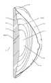
- FIG. 1is a schematic isometric angled front view of an exemplary radome mounted on the reflector dish of a reflector antenna.
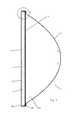
- FIG. 2is a schematic isometric angled back view of the reflector antenna of FIG. 1 , with the antenna hub and mounting assembly removed for clarity.
- FIG. 3is a schematic cut-away side view of the reflector antenna of FIG. 1 , with the feed assembly, antenna hub and mounting assembly removed for clarity.
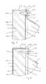
- FIG. 4is a close-up view of area C of FIG. 3 .
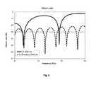
- FIG. 5is a calculated insertion loss chart comparing an exemplary radome to a prior art radome.
- FIG. 6is a calculated return loss chart comparing an exemplary radome to a prior art radome.
- FIG. 7is a schematic close-up view of an alternative embodiment of a radome coupled to a reflector dish, demonstrating the outer layer extending over the outer diameter of the structural layer.
- FIG. 8is a schematic close-up view of an alternative embodiment of a radome coupled to a reflector dish, demonstrating the outer layer extending around the outer diameter to the inner side of the structural layer.
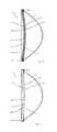
- FIG. 9is a schematic cut-away side view of an alternative embodiment of a radome coupled to a reflector antenna, demonstrating a domed radome profile. The feed assembly, antenna hub and mounting assembly have been removed for clarity.
- FIG. 10is a schematic cut-away side view of an alternative embodiment of a radome coupled to a reflector antenna, demonstrating a domed outer radome profile. The feed assembly, antenna hub and mounting assembly have been removed for clarity.
- FIG. 11is a schematic cut-away side view of an alternative embodiment of a radome coupled to a reflector antenna, demonstrating a domed radome profile.
- the feed assembly, antenna hub and mounting assemblyhave been removed for clarity.
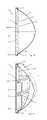
- FIG. 12is a schematic cut-away side view of an alternative embodiment of a radome coupled to a reflector antenna, demonstrating an inwardly domed radome profile.
- the feed assembly, antenna hub and mounting assemblyhave been removed for clarity.
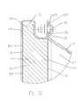
- FIG. 13is a schematic cut-away side view of an alternative embodiment of a radome coupled to a reflector antenna, demonstrating an inwardly conical radome profile.
- the feed assembly, antenna hub and mounting assemblyhave been removed for clarity.
- FIG. 14is a schematic cut-away side view of an alternative embodiment of a radome coupled to a reflector antenna, demonstrating an angled planar face radome profile, with an angled rear face.
- the feed assembly, antenna hub and mounting assemblyhave been removed for clarity.
- FIG. 15is a schematic cut-away side view of an alternative embodiment of a radome coupled to a reflector antenna, demonstrating an angled planar face radome profile with a flat rear face. The feed assembly, antenna hub and mounting assembly have been removed for clarity.
- FIG. 16is a schematic isometric view of an alternative embodiment of a radome coupled to a reflector antenna, demonstrating an angled planar dual face radome profile with flat rear face. The feed assembly, antenna hub and mounting assembly have been removed for clarity.
- FIG. 17is a schematic cut-away side view of the reflector antenna of FIG. 16 , with the feed assembly, antenna hub and mounting assembly removed for clarity.
- FIG. 18is a schematic isometric view of an alternative embodiment of a radome coupled to a reflector antenna, demonstrating an angled planar quad face radome profile with a flat rear face. The feed assembly, antenna hub and mounting assembly have been removed for clarity.
- FIG. 19is a schematic cut-away side view of the reflector antenna of FIG. 18 , with the feed assembly, antenna hub and mounting assembly removed for clarity.
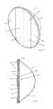
- FIG. 20is a schematic cut-away side view of an alternative embodiment of a radome coupled to a reflector antenna, demonstrating a structural layer projecting inwardly to the signal space of the reflector dish.
- the feed assembly, antenna hub and mounting assemblyhave been removed for clarity.
- FIG. 21is a schematic cut-away side view of an alternative embodiment of a radome coupled to a reflector antenna, demonstrating a structural layer projecting inwardly to the signal space of the reflector dish.
- the feed assembly, antenna hub and mounting assemblyhave been removed for clarity.
- FIG. 22is a schematic isometric cut-away view of an alternative embodiment of a radome coupled to a reflector antenna, demonstrating a conical inward protrusion.
- the feed assembly, antenna hub and mounting assemblyhave been removed for clarity.
- FIG. 23is a schematic isometric cut-away view of an alternative embodiment of a radome coupled to a reflector antenna, demonstrating concentric ring inward protrusions. The feed assembly, antenna hub and mounting assembly have been removed for clarity.
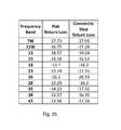
- FIG. 24is a schematic isometric cut-away view of an alternative embodiment of a radome coupled to a reflector antenna, demonstrating concentric step inward protrusions.
- the feed assembly, antenna hub and mounting assemblyhave been removed for clarity.
- FIG. 25is a table of range measurements comparing broadband return loss (in dB) characteristics over a wide range of frequency bands of a flat outer side and flat inner side composite radome in contrast with a flat outer side composite radome with the same outer layer and structural layer materials (0.5 mm polycarbonate film and 25 mm expanded polystryrene foam, respectively), which includes inward projections formed as concentric steps in successive 25 mm step increments.
- in dBbroadband return loss
- FIG. 26is a schematic close-up view of an alternative embodiment of a radome coupled to a reflector dish, demonstrating a retaining flange with a periphery portion.
- FIG. 27is a schematic close-up view of an alternative embodiment of a radome coupled to a reflector dish, demonstrating through fastening between the retaining flange and the retaining element.
- FIG. 28is a schematic close-up view of an alternative embodiment of a radome coupled to a reflector dish, demonstrating overlapping of the retaining flange and the retaining element.
- FIG. 29is a schematic close-up view of an alternative embodiment of a radome coupled to a reflector dish, demonstrating an RF absorber seated in a periphery shoulder of the structural layer.
- FIG. 30is a schematic close-up view of an alternative embodiment of a radome coupled to a reflector dish, demonstrating a retaining element with an S-shaped cross-section with inner and outer choke grooves.
- FIG. 31is a schematic close-up view of an alternative embodiment of a radome coupled to a reflector dish, demonstrating a radome coupled without a retaining element, with a conductive edge and the outer layer represented separate from the structural layer for clarity.
- FIG. 32is a schematic close-up view of an alternative embodiment of a radome coupled to a reflector dish, demonstrating a radome coupled without a retaining element, with a conductive edge and the outer layer represented separate from the structural layer for clarity.
- the inventorshave recognized that a composite of a moisture resistant isotropic film outer layer and a structural layer of low density foamed polymer material can result in a radome with adequate strength which is essentially RF transparent, enabling a single radome to be utilized with a broad range of microwave frequency bands.
- a radome 1has an isotropic outer layer 3 coupled to a structural layer 5 of foam material that is retained on a reflector dish 7 , a seating surface 8 of the radome 1 mating with a retaining flange at the distal end of the reflector dish 7 , enclosing an open end of the reflector antenna 9 .
- An isotropic material as applied hereinis one in which the material has a substantially homogeneous distribution. That is, the material is not a woven or fiber infused material, but a substantially uniformly distributed homogeneous material, such as a polymer film, coating or the like.
- the outer layer 3may be, for example, a polymer and/or blend of polymers, such as polycarbonate, acrylonitrile styrene acrylate, polyvinyl chloride, polymethyl methacrylate, thermoplastic polyolefin, ethylene-vinyl acetate, acrylonitrile-butadiene-styrene or the like.
- polymerssuch as polycarbonate, acrylonitrile styrene acrylate, polyvinyl chloride, polymethyl methacrylate, thermoplastic polyolefin, ethylene-vinyl acetate, acrylonitrile-butadiene-styrene or the like.
- the outer layer 3may be a film applied upon the structural layer 5 or a coating sprayed or painted upon the structural layer 5 .
- the outer layer 3may provide ultra-violet and/or impact protection for the structural layer 5 as well as a moisture barrier to inhibit moisture from being absorbed into the foam material of the structural layer 5 , which could otherwise degrade the structural integrity and/or electrical performance of the radome 1 .
- Any outer layer 3 with suitable moisture and ultra-violet radiation resistance characteristicsmay be applied.
- the outer layer 3may include signage and/or graphics for aesthetics and/or marketing purposes. In a balance between moisture resistance and material cost, the outer layer 3 may be provided with a thickness of 0.5 millimeters or less.
- U.S. Utility Pat. No. 4,896,164“Radar Transparent Window for Commercial Buildings”, issued to Burke et al, Jan. 23, 1990, describes a conventional tuned sandwich radome structure (FIG. 2 of U.S. Pat. No. 4,896,164) with interior and exterior layers of polyester resin/E-glass (fiberglass) laminate provided on front and back sides of a rigid polyimide foam with a specific thickness selected with respect to conventional reflection cancellation.
- an exemplary embodiment of a 0.1 mm thick outer layer 3 (2.8 dielectric constant) and 25 mm structural layer 5 (1.11 dielectric constant)with an uncovered signal transmission surface 11 at the inner side 13 has a significantly improved broadband characteristic with respect to insertion and return loss, as demonstrated in FIGS. 5 and 6 , respectively.
- the insertion loss of the exemplary embodiment composite radomeis minimal over the 36 GHz range between 6 and 42 GHz
- the prior tuned structureis effectively unusable outside of two narrow 4 GHz wide bands of 8-12 and 27-31 GHz.
- the outer layer 3may extend proximate to an outer diameter 15 of the structural layer 5 ( FIG. 4 ), to the outer diameter 15 of the structural layer 5 ( FIG. 7 ) and/or around the outer diameter 15 to the inner side 13 of the structural layer 5 , without extending radially inward to the signal transmission surface 11 of the inner side 13 ( FIG. 8 ).
- the reflector dish 7With the radome 1 seated upon the open end of the reflector dish 7 , the reflector dish 7 provides the remainder of the moisture seal with respect to the cavity enclosed by the radome 1 , so that the inner side 13 of the structural layer 5 , or just the signal transmission surface 11 of the inner side 13 , may be uncovered.
- the structural layer 5may be provided as a foamed polymer such as polystyrene, polyurethane, polyethylene, polypropylene or the like.
- the structural layer 5may be provided with a thickness selected with respect to structural properties of the selected material and/or the necessary diameter of the radome to provide a structural strength to the resulting radome 1 which corresponds to a strength and/or rigidity required for the range of environmental conditions expected at the desired reflector antenna 9 installation(s).
- the structural layer 5may be provided with a thickness from a distal end of the reflector dish 7 of at least 2 wavelengths of a minimum operating frequency, such that a conductive retaining element 23 or conductive edge 41 applied at the radome periphery is also operative as a shield portion inhibiting generation of backlobes in the signal pattern of the resulting antenna 9 .
- a 25 mm thick structural layer 5may be applied, for example, as a compromise thickness for broadband performance.
- the foamed polymer of the structural layer 5may be cut to size or cost efficiently molded with a high level of precision, in any desired profile.
- the radome 1may be provided with a profile configured to extend inwardly or outwardly with respect to the plane of the seating surface 8 , along a longitudinal axis of the radome (also the signal beam axis of the reflector antenna 1 ) to further reduce return loss, enhance wind loading, and/or improve the strength characteristics of the radome.
- a domed profilemay be applied wherein the center of the radome arcs outwardly or inwardly from the periphery of the radome, for example as shown in FIGS. 9-12 .
- the inner side 13 of the radome 1may be provided flat ( FIG.
- the inward or outward extension of the radome 1may be conical, for example as shown in FIG. 13 , and/or the radome 1 may be provided with an angled front face 24 and angled or flat back face (with respect to a plane of the seating surface 8 ), for example as shown in FIGS. 14 and 15 , which may improve ice shedding and/or return loss characteristics of the reflector antenna 9 .
- the front face 24may alternatively be provided as a plurality of planar front faces 24 .
- the features of the outer side 14 of the structural layer 5upon which the outer layer 3 is applied, may be provided with each front face 24 aligned with a common axis, such as the vertical axis, so that no creases are generated by projections or cavities which the intersection of non-aligned angled faces may otherwise generate.
- FIGS. 16 and 17demonstrate two planar front faces 24 arranged to form a peak extension from the plane of the seating surface 8 parallel to a vertical axis of the radome.
- planar front faces 24demonstrate four planar front faces 24 with each planar front face 24 also aligned parallel to a vertical axis of the radome 1 .
- planar vertical axis angled front face embodimentsmay be useful, for example, for addressing undesirable side lobes in the reflector antenna signal pattern.
- An increased thickness of the structural layer 5may be applied by configuring the inner side 13 of the structural layer 5 , in particular the signal transmission surface 11 encircled by the annular seating surface 8 , to extend inward with respect to the plane of the seating surface 8 , within the signal space of the reflector dish 7 .
- the signal transmission surface 11 at the inner side 13 of the structural layer 5may be provided with one or more inward projections 19 , dimensioned to extend inwardly from the distal end of the reflector dish 7 , seating also along the inner signal surface 17 of the reflector dish 7 , for example as shown in FIGS. 20 and 21 .
- the inward projections 19 of the structural layer 5may be applied as reinforcing rings and/or ribs, for example as shown in FIG. 21 , which extend inward of the plane of the seating surface 8 and the retaining flange 29 of the reflector dish 7 of the antenna, along a longitudinal axis of the radome.
- the inward projections 19may be positioned for reduced presence in primary signal pattern positions, such as the horizontal and vertical axis of the radome.
- Additional improvement with respect to reducing the return loss characteristics of the radome 1may be obtained via tuning of the inward projections 19 , including, for example, use of conical, annular concentric grooves 20 and/or concentric steps 22 , for example as shown in FIGS. 22-24 .
- Range measurements comparing broadband return loss (in dB) characteristics over a wide range of frequency bands of a composite radome 1 with a flat outer side 14 and a flat inner side 13see FIG.
- the radome 1may be coupled to the reflector dish 7 , retained along the seating surface 8 against the distal end of the reflector dish 7 via fasteners 21 such as screws or the like which retain the radome directly upon the distal end of the reflector dish 7 and/or which secure a retaining element 23 , such as a metal band, which may protect the periphery of the radome 1 and/or further secure the radome 1 in place.
- the fasteners 21may extend through the retaining element 23 and into the structural layer 5 ( FIGS. 4, 26 ) or fully through the structural layer 5 and two edges of the retaining element 23 ( FIG. 27 ).
- the retaining element 23may be applied with an outer edge 25 seated against an outer surface 27 of the retaining flange 29 of the reflector dish 7 , for example as shown in FIG. 4 .
- the retaining element 23may seat against an inner seat surface 31 of the retaining flange 29 ( FIG. 28 ), providing an overlapping mechanical interlock between the elements and extending the path required for signal leakage to occur therebetween.
- the retaining flange 29may be formed with a periphery portion 33 coaxial with a longitudinal axis of the reflector antenna 9 , enabling the retaining element 23 to be provided with an “L” (rather than “C”) cross-section, the retaining element 23 retained by fasteners 21 extending radially inwardly through the periphery portion 33 into the retaining element 23 and further into the radome 1 , as shown for example in FIG. 26 .
- the retaining element 23may also be utilized to retain an RF absorber 35 seated in a periphery shoulder 37 of the radome 1 , for example as shown in FIG. 29 .
- the retaining element 23may be further provided in a generally S-shaped cross-section, dimensioned to provide both an inward and an outward facing choke groove 39 for inhibiting back lobes in the resulting reflector antenna signal pattern, for example as shown in FIG. 30 .
- this configurationalso enables a fastener 21 (provided, for example, as a bolt and nut) to avoid penetrating the structural layer or a signal area of the radome 1 , which may avoid secondary sealing issues created by multiple fasteners 21 penetrating through the retaining element 23 into the signal area of the radome 1 itself.
- a fastener 21provided, for example, as a bolt and nut
- the radome 1may also be retained on the distal end of the reflector dish, without an additional retaining element 23 .
- a conductive edge 41formed for example via metalizing, electrodaging, overmolding, metallic paint, foil or the like, may be applied to assist with signal pattern backlobe cancellation either on top of or under the outer layer 3 , for example as shown in FIGS. 31 and 32 .
- the bonding of the outer layer 3 to the structural layer 5may be secured, for example, by application of an adhesive therebetween and/or integrally with a molding/foaming process of the structural layer 5 .
- an initial molding of the structural layer 5may be performed and the mold opened for insertion of the outer layer 3 .
- the outer layer 3may be applied via spraying, either upon the mold or upon the structural layer 5 . With the outer layer 3 in place, the mold may be closed again and final molding/foaming completed with an additional time period.
- the outer layer 3may be inserted or sprayed into an empty mold and the structural layer 5 molded upon it. Thereby, the composite of the structural layer 5 and outer layer 3 may be formed without use of an additional adhesive.
- the moldmay include vacuum-forming functionality to draw the outer layer 3 into the desired extent, either in a separate operation or via vacuum forming the thin film of the outer layer 3 in situ within the mold before the structural layer 5 is foamed on top of it.
- the outer layer 3may be heat shrunk upon the structural layer 5 .
- the ability to provide a single cost efficient radome 1may enable significant reflector antenna manufacturing cost efficiencies.
- the self supporting characteristic of the structural layerenables simplified radome to reflector antenna attachment arrangements with electrical performance enhancing characteristics that may also be cost effective and/or easily adaptable to a wide range of different reflector dishes 7 .
Landscapes
- Physics & Mathematics (AREA)
- Electromagnetism (AREA)
- Details Of Aerials (AREA)
Abstract
Description
| Table of |
| 1 | |
| 3 | |
| 5 | |
| 7 | |
| 8 | |
| 9 | |
| 11 | |
| 13 | |
| 14 | |
| 15 | |
| 17 | |
| 19 | |
| 20 | |
| 21 | fastener |
| 22 | |
| 23 | retaining |
| 24 | |
| 25 | |
| 27 | |
| 29 | retaining |
| 31 | |
| 33 | |
| 35 | |
| 37 | periphery shoulder |
| 39 | |
| 41 | conductive edge |
Claims (12)
Priority Applications (1)
| Application Number | Priority Date | Filing Date | Title |
|---|---|---|---|
| US14/527,803US9985347B2 (en) | 2013-10-30 | 2014-10-30 | Broad band radome for microwave antenna |
Applications Claiming Priority (2)
| Application Number | Priority Date | Filing Date | Title |
|---|---|---|---|
| US14/066,755US9583822B2 (en) | 2013-10-30 | 2013-10-30 | Broad band radome for microwave antenna |
| US14/527,803US9985347B2 (en) | 2013-10-30 | 2014-10-30 | Broad band radome for microwave antenna |
Related Parent Applications (1)
| Application Number | Title | Priority Date | Filing Date |
|---|---|---|---|
| US14/066,755Continuation-In-PartUS9583822B2 (en) | 2013-10-30 | 2013-10-30 | Broad band radome for microwave antenna |
Publications (2)
| Publication Number | Publication Date |
|---|---|
| US20170301983A1 US20170301983A1 (en) | 2017-10-19 |
| US9985347B2true US9985347B2 (en) | 2018-05-29 |
Family
ID=60038471
Family Applications (1)
| Application Number | Title | Priority Date | Filing Date |
|---|---|---|---|
| US14/527,803Active2035-09-29US9985347B2 (en) | 2013-10-30 | 2014-10-30 | Broad band radome for microwave antenna |
Country Status (1)
| Country | Link |
|---|---|
| US (1) | US9985347B2 (en) |
Cited By (1)
| Publication number | Priority date | Publication date | Assignee | Title |
|---|---|---|---|---|
| TWI863321B (en)* | 2023-05-31 | 2024-11-21 | 明泰科技股份有限公司 | Radome and radar using the same |
Families Citing this family (9)
| Publication number | Priority date | Publication date | Assignee | Title |
|---|---|---|---|---|
| EP3298655A4 (en)* | 2015-05-21 | 2019-01-16 | Commscope Technologies LLC | Segmented antenna radome |
| WO2020076918A1 (en)* | 2018-10-12 | 2020-04-16 | Commscope Technologies Llc | Flexible radome structures |
| CN112018575A (en)* | 2019-05-31 | 2020-12-01 | 康普技术有限责任公司 | Base station antenna and end cover assembly and method of assembling and disassembling the same |
| US11226397B2 (en)* | 2019-08-06 | 2022-01-18 | Waymo Llc | Slanted radomes |
| US11385325B2 (en)* | 2019-08-07 | 2022-07-12 | Waymo Llc | Corrugated radomes |
| CN110797656B (en)* | 2019-12-05 | 2024-08-13 | 广州市瀚云信息技术有限公司 | 5G mobile communication AAU antenna housing |
| CN113471657A (en)* | 2020-03-31 | 2021-10-01 | 华为技术有限公司 | Antenna device |
| EP3985798A4 (en)* | 2020-07-23 | 2023-01-18 | Rosenberger Technologies Co., Ltd. | Apparatus for reducing wind resistance of antenna |
| CN113346235B (en)* | 2021-06-12 | 2022-11-22 | 中国电子科技集团公司第二十研究所 | A Composite Material Antenna Transparent Cover and Its Broadband Electric Thickness Control and Manufacturing Method |
Citations (43)
| Publication number | Priority date | Publication date | Assignee | Title |
|---|---|---|---|---|
| US2614059A (en) | 1949-05-06 | 1952-10-14 | Rubatex Products Inc | Method of making radar domes |
| US3002190A (en) | 1955-04-15 | 1961-09-26 | Zenith Plastics Company | Multiple sandwich broad band radome |
| US3432859A (en) | 1963-01-29 | 1969-03-11 | Gen Electric | Radome and method for making same |
| US4148039A (en) | 1977-07-05 | 1979-04-03 | The Boeing Company | Low reflectivity radome |
| US4620890A (en) | 1982-06-07 | 1986-11-04 | Hitco | Method of making a fluted core radome |
| US4872019A (en)* | 1986-12-09 | 1989-10-03 | Her Majesty The Queen In Right Of Canada As Represented By The Minister Of National Defence | Radome-lens EHF antenna development |
| US4896164A (en) | 1988-08-30 | 1990-01-23 | Grumman Aerospace Corporation | Radar transparent window for commercial buildings |
| EP0359504A1 (en) | 1988-09-14 | 1990-03-21 | British Aerospace Public Limited Company | Radomes |
| GB2225902A (en) | 1988-10-14 | 1990-06-13 | Cambridge Computer | Dish antenna |
| US4980696A (en) | 1987-05-12 | 1990-12-25 | Sippican Ocean Systems, Inc. | Radome for enclosing a microwave antenna |
| US5323170A (en) | 1992-10-09 | 1994-06-21 | M & N Aerospace, Inc. | Radomes having vinyl foam core construction |
| US5408244A (en) | 1991-01-14 | 1995-04-18 | Norton Company | Radome wall design having broadband and mm-wave characteristics |
| US5457471A (en) | 1984-09-10 | 1995-10-10 | Hughes Missile Systems Company | Adaptively ablatable radome |
| US5486399A (en) | 1992-01-13 | 1996-01-23 | Space Systems/Loral, Inc. | Self-supporting convex cover for spacecraft |
| US5662293A (en) | 1995-05-05 | 1997-09-02 | Hower; R. Thomas | Polyimide foam-containing radomes |
| JPH10200328A (en)* | 1997-01-13 | 1998-07-31 | Furukawa Electric Co Ltd:The | Radar antenna |
| US5845391A (en) | 1994-06-13 | 1998-12-08 | Northrop Grumman Corporation | Method of making antenna array panel structure |
| US5849234A (en) | 1996-02-16 | 1998-12-15 | Mcdonnell Douglas Technologies, Inc. | Multilayer radome structure and its fabrication |
| US6107976A (en) | 1999-03-25 | 2000-08-22 | Bradley B. Teel | Hybrid core sandwich radome |
| US6184842B1 (en) | 1998-05-02 | 2001-02-06 | Daimlerchrysler | Process for manufacturing a radome for a range warning radar |
| US6375779B1 (en) | 1997-10-08 | 2002-04-23 | Mcdonnell Douglas Helicopter Company | Method for making structures having low radar reflectivity |
| US6380904B1 (en) | 1999-09-30 | 2002-04-30 | Kabushiki Kaisha Toshiba | Antenna apparatus |
| US20020093459A1 (en) | 2001-01-12 | 2002-07-18 | Butler Jeffrey T. | Low profile antenna radome element with rib reinforcements |
| US20040113305A1 (en) | 2002-12-12 | 2004-06-17 | The Boeing Company | Method for making a radome |
| US20050190116A1 (en) | 2004-02-27 | 2005-09-01 | Andrew Corporation | Reflector antenna radome with backlobe suppressor ring and method of manufacturing |
| US6992640B2 (en) | 2003-06-09 | 2006-01-31 | Mitsubishi Denki Kabushiki Kaisha | Radome |
| US7242365B1 (en) | 2004-04-08 | 2007-07-10 | Lockheed Martin Corporation | Seam arrangement for a radome |
| US7446730B2 (en) | 2004-05-18 | 2008-11-04 | Electronic Navigation Research Institute | Radio wave device |
| US7463212B1 (en) | 2005-09-14 | 2008-12-09 | Radant Technologies, Inc. | Lightweight C-sandwich radome fabrication |
| US7554499B2 (en) | 2006-04-26 | 2009-06-30 | Harris Corporation | Radome with detuned elements and continuous wires |
| US7656363B2 (en) | 2005-12-06 | 2010-02-02 | Alcatel Lucent | Radio communication antenna fitted with a radome and method of assembling this kind of radio communication antenna fitted with a radome |
| JP2010171860A (en)* | 2009-01-26 | 2010-08-05 | Nec Corp | Radome, and manufacturing method thereof |
| US20100315307A1 (en) | 2009-06-12 | 2010-12-16 | Andrew Llc | Radome and Shroud Enclosure for Reflector Antenna |
| US20110140983A1 (en) | 2009-12-11 | 2011-06-16 | Andrew Llc | Reflector Antenna Radome Attachment Band Clamp |
| US20110234468A1 (en) | 2008-12-05 | 2011-09-29 | Norihiko Omuro | Antenna device and communication device provided therewith |
| US8059049B2 (en) | 2006-10-11 | 2011-11-15 | Raytheon Company | Dual band active array antenna |
| US20110285604A1 (en) | 2008-12-11 | 2011-11-24 | Armel Le Bayon | Radome for broadband parabolic antenna |
| US8130167B2 (en) | 2009-04-10 | 2012-03-06 | Coi Ceramics, Inc. | Radomes, aircraft and spacecraft including such radomes, and methods of forming radomes |
| US20120075161A1 (en) | 2010-05-17 | 2012-03-29 | Robert Elwell | Radome |
| US20120262331A1 (en) | 2011-04-18 | 2012-10-18 | Klaus Kienzle | Filling level measuring device antenna cover |
| DE102011076501A1 (en) | 2011-05-26 | 2012-11-29 | Robert Bosch Gmbh | Cover for radar sensor assembly of motor vehicle, has several heating elements that are provided in the plastic outer skin |
| WO2012163237A1 (en) | 2011-05-27 | 2012-12-06 | 京信通信系统(中国)有限公司 | Broadband shaped antenna radome and microwave antenna |
| US20130002515A1 (en) | 2009-12-11 | 2013-01-03 | Andrew Llc | Radome Attachment Band Clamp |
- 2014
- 2014-10-30USUS14/527,803patent/US9985347B2/enactiveActive
Patent Citations (43)
| Publication number | Priority date | Publication date | Assignee | Title |
|---|---|---|---|---|
| US2614059A (en) | 1949-05-06 | 1952-10-14 | Rubatex Products Inc | Method of making radar domes |
| US3002190A (en) | 1955-04-15 | 1961-09-26 | Zenith Plastics Company | Multiple sandwich broad band radome |
| US3432859A (en) | 1963-01-29 | 1969-03-11 | Gen Electric | Radome and method for making same |
| US4148039A (en) | 1977-07-05 | 1979-04-03 | The Boeing Company | Low reflectivity radome |
| US4620890A (en) | 1982-06-07 | 1986-11-04 | Hitco | Method of making a fluted core radome |
| US5457471A (en) | 1984-09-10 | 1995-10-10 | Hughes Missile Systems Company | Adaptively ablatable radome |
| US4872019A (en)* | 1986-12-09 | 1989-10-03 | Her Majesty The Queen In Right Of Canada As Represented By The Minister Of National Defence | Radome-lens EHF antenna development |
| US4980696A (en) | 1987-05-12 | 1990-12-25 | Sippican Ocean Systems, Inc. | Radome for enclosing a microwave antenna |
| US4896164A (en) | 1988-08-30 | 1990-01-23 | Grumman Aerospace Corporation | Radar transparent window for commercial buildings |
| EP0359504A1 (en) | 1988-09-14 | 1990-03-21 | British Aerospace Public Limited Company | Radomes |
| GB2225902A (en) | 1988-10-14 | 1990-06-13 | Cambridge Computer | Dish antenna |
| US5408244A (en) | 1991-01-14 | 1995-04-18 | Norton Company | Radome wall design having broadband and mm-wave characteristics |
| US5486399A (en) | 1992-01-13 | 1996-01-23 | Space Systems/Loral, Inc. | Self-supporting convex cover for spacecraft |
| US5323170A (en) | 1992-10-09 | 1994-06-21 | M & N Aerospace, Inc. | Radomes having vinyl foam core construction |
| US5845391A (en) | 1994-06-13 | 1998-12-08 | Northrop Grumman Corporation | Method of making antenna array panel structure |
| US5662293A (en) | 1995-05-05 | 1997-09-02 | Hower; R. Thomas | Polyimide foam-containing radomes |
| US5849234A (en) | 1996-02-16 | 1998-12-15 | Mcdonnell Douglas Technologies, Inc. | Multilayer radome structure and its fabrication |
| JPH10200328A (en)* | 1997-01-13 | 1998-07-31 | Furukawa Electric Co Ltd:The | Radar antenna |
| US6375779B1 (en) | 1997-10-08 | 2002-04-23 | Mcdonnell Douglas Helicopter Company | Method for making structures having low radar reflectivity |
| US6184842B1 (en) | 1998-05-02 | 2001-02-06 | Daimlerchrysler | Process for manufacturing a radome for a range warning radar |
| US6107976A (en) | 1999-03-25 | 2000-08-22 | Bradley B. Teel | Hybrid core sandwich radome |
| US6380904B1 (en) | 1999-09-30 | 2002-04-30 | Kabushiki Kaisha Toshiba | Antenna apparatus |
| US20020093459A1 (en) | 2001-01-12 | 2002-07-18 | Butler Jeffrey T. | Low profile antenna radome element with rib reinforcements |
| US20040113305A1 (en) | 2002-12-12 | 2004-06-17 | The Boeing Company | Method for making a radome |
| US6992640B2 (en) | 2003-06-09 | 2006-01-31 | Mitsubishi Denki Kabushiki Kaisha | Radome |
| US20050190116A1 (en) | 2004-02-27 | 2005-09-01 | Andrew Corporation | Reflector antenna radome with backlobe suppressor ring and method of manufacturing |
| US7242365B1 (en) | 2004-04-08 | 2007-07-10 | Lockheed Martin Corporation | Seam arrangement for a radome |
| US7446730B2 (en) | 2004-05-18 | 2008-11-04 | Electronic Navigation Research Institute | Radio wave device |
| US7463212B1 (en) | 2005-09-14 | 2008-12-09 | Radant Technologies, Inc. | Lightweight C-sandwich radome fabrication |
| US7656363B2 (en) | 2005-12-06 | 2010-02-02 | Alcatel Lucent | Radio communication antenna fitted with a radome and method of assembling this kind of radio communication antenna fitted with a radome |
| US7554499B2 (en) | 2006-04-26 | 2009-06-30 | Harris Corporation | Radome with detuned elements and continuous wires |
| US8059049B2 (en) | 2006-10-11 | 2011-11-15 | Raytheon Company | Dual band active array antenna |
| US20110234468A1 (en) | 2008-12-05 | 2011-09-29 | Norihiko Omuro | Antenna device and communication device provided therewith |
| US20110285604A1 (en) | 2008-12-11 | 2011-11-24 | Armel Le Bayon | Radome for broadband parabolic antenna |
| JP2010171860A (en)* | 2009-01-26 | 2010-08-05 | Nec Corp | Radome, and manufacturing method thereof |
| US8130167B2 (en) | 2009-04-10 | 2012-03-06 | Coi Ceramics, Inc. | Radomes, aircraft and spacecraft including such radomes, and methods of forming radomes |
| US20100315307A1 (en) | 2009-06-12 | 2010-12-16 | Andrew Llc | Radome and Shroud Enclosure for Reflector Antenna |
| US20110140983A1 (en) | 2009-12-11 | 2011-06-16 | Andrew Llc | Reflector Antenna Radome Attachment Band Clamp |
| US20130002515A1 (en) | 2009-12-11 | 2013-01-03 | Andrew Llc | Radome Attachment Band Clamp |
| US20120075161A1 (en) | 2010-05-17 | 2012-03-29 | Robert Elwell | Radome |
| US20120262331A1 (en) | 2011-04-18 | 2012-10-18 | Klaus Kienzle | Filling level measuring device antenna cover |
| DE102011076501A1 (en) | 2011-05-26 | 2012-11-29 | Robert Bosch Gmbh | Cover for radar sensor assembly of motor vehicle, has several heating elements that are provided in the plastic outer skin |
| WO2012163237A1 (en) | 2011-05-27 | 2012-12-06 | 京信通信系统(中国)有限公司 | Broadband shaped antenna radome and microwave antenna |
Non-Patent Citations (6)
| Title |
|---|
| European Search Report Corresponding to European Patent Application No. 14 857 532.7; dated May 30, 2017; 10 pages. |
| European Search Report Corresponding to European Patent Application No. 14 857 784.4; dated May 30, 2017; 10 pages. |
| Office Action corresponding to Chinese Application No. 201480059475.6; dated Dec. 5, 2017; 9 pages. |
| Office Action corresponding to Chinese Application No. 201480059476.0; dated Dec. 5, 2017; 10 pages. |
| Sung Chul Kang, International Search Report for PCT application PCT/US14/62766, dated Jan. 13, 2015, Korean Intellectual Property Office, Metropolitan City, Daejeon, Republic of Korea. |
| Sung Chul Kang, International Search Report for PCT application PCT/US2014/063020, dated Feb. 26, 2015, Korean Intellectual Property Office, Daejeon Metropolitan City, Republic of Korea. |
Cited By (1)
| Publication number | Priority date | Publication date | Assignee | Title |
|---|---|---|---|---|
| TWI863321B (en)* | 2023-05-31 | 2024-11-21 | 明泰科技股份有限公司 | Radome and radar using the same |
Also Published As
| Publication number | Publication date |
|---|---|
| US20170301983A1 (en) | 2017-10-19 |
Similar Documents
| Publication | Publication Date | Title |
|---|---|---|
| EP3063831B1 (en) | Broad band radome for microwave antenna | |
| US9985347B2 (en) | Broad band radome for microwave antenna | |
| US12218425B2 (en) | Base station antennas having reflector assemblies including a nonmetallic substrate having a metallic layer thereon | |
| EP2615688B1 (en) | Microwave antenna and its outer cover | |
| EP1852938B1 (en) | Antenna radome | |
| US11984655B2 (en) | Wideband radome design | |
| US10050340B2 (en) | Radome | |
| US20080252552A1 (en) | Antenna Housing and Antennas with Such Antenna Housings | |
| WO2010144455A1 (en) | Planar array antenna having radome over protruding antenna elements | |
| US12176621B2 (en) | Integrated base station antenna | |
| EP3619041B1 (en) | Aircraft radomes with broadband transparency | |
| WO2021167718A1 (en) | An improved radome for a base station antenna and a base station antenna using such a radome | |
| KR102087385B1 (en) | Streamline-shaped Radome and Method for Manufacturing The same | |
| CN112886241A (en) | Radome, reflector and feed assembly for microwave antennas | |
| EP3912225B1 (en) | Combined antenna and radome arrangement | |
| JP5263957B2 (en) | Radome and manufacturing method thereof | |
| CN201859944U (en) | Microwave antenna and outer housing thereof | |
| CN107667450A (en) | Segmented Radome | |
| US20240397685A1 (en) | Adjustable broadband radar absorber | |
| WO2018149220A1 (en) | Antenna cover and antenna | |
| CN202103164U (en) | Broadband shaped antenna housing and microwave antenna | |
| CN212517521U (en) | Antenna housing for millimeter wave radar | |
| EP2891211B1 (en) | Radome attachment band clamp |
Legal Events
| Date | Code | Title | Description |
|---|---|---|---|
| AS | Assignment | Owner name:ANDREW LLC, NORTH CAROLINA Free format text:ASSIGNMENT OF ASSIGNORS INTEREST;ASSIGNORS:CURRAN, JOHN;RENILSON, IAN;WRIGHT, ALASTAIR D;AND OTHERS;REEL/FRAME:034101/0481 Effective date:20141029 | |
| AS | Assignment | Owner name:COMMSCOPE TECHNOLOGIES LLC, NORTH CAROLINA Free format text:CHANGE OF NAME;ASSIGNOR:ANDREW LLC;REEL/FRAME:035226/0385 Effective date:20150301 | |
| AS | Assignment | Owner name:WILMINGTON TRUST, NATIONAL ASSOCIATION, AS COLLATERAL AGENT, CONNECTICUT Free format text:SECURITY INTEREST;ASSIGNORS:ALLEN TELECOM LLC;COMMSCOPE TECHNOLOGIES LLC;COMMSCOPE, INC. OF NORTH CAROLINA;AND OTHERS;REEL/FRAME:036201/0283 Effective date:20150611 Owner name:WILMINGTON TRUST, NATIONAL ASSOCIATION, AS COLLATE Free format text:SECURITY INTEREST;ASSIGNORS:ALLEN TELECOM LLC;COMMSCOPE TECHNOLOGIES LLC;COMMSCOPE, INC. OF NORTH CAROLINA;AND OTHERS;REEL/FRAME:036201/0283 Effective date:20150611 | |
| AS | Assignment | Owner name:COMMSCOPE, INC. OF NORTH CAROLINA, NORTH CAROLINA Free format text:RELEASE OF SECURITY INTEREST PATENTS (RELEASES RF 036201/0283);ASSIGNOR:WILMINGTON TRUST, NATIONAL ASSOCIATION;REEL/FRAME:042126/0434 Effective date:20170317 Owner name:COMMSCOPE TECHNOLOGIES LLC, NORTH CAROLINA Free format text:RELEASE OF SECURITY INTEREST PATENTS (RELEASES RF 036201/0283);ASSIGNOR:WILMINGTON TRUST, NATIONAL ASSOCIATION;REEL/FRAME:042126/0434 Effective date:20170317 Owner name:ALLEN TELECOM LLC, NORTH CAROLINA Free format text:RELEASE OF SECURITY INTEREST PATENTS (RELEASES RF 036201/0283);ASSIGNOR:WILMINGTON TRUST, NATIONAL ASSOCIATION;REEL/FRAME:042126/0434 Effective date:20170317 Owner name:REDWOOD SYSTEMS, INC., NORTH CAROLINA Free format text:RELEASE OF SECURITY INTEREST PATENTS (RELEASES RF 036201/0283);ASSIGNOR:WILMINGTON TRUST, NATIONAL ASSOCIATION;REEL/FRAME:042126/0434 Effective date:20170317 | |
| STCF | Information on status: patent grant | Free format text:PATENTED CASE | |
| AS | Assignment | Owner name:JPMORGAN CHASE BANK, N.A., NEW YORK Free format text:TERM LOAN SECURITY AGREEMENT;ASSIGNORS:COMMSCOPE, INC. OF NORTH CAROLINA;COMMSCOPE TECHNOLOGIES LLC;ARRIS ENTERPRISES LLC;AND OTHERS;REEL/FRAME:049905/0504 Effective date:20190404 Owner name:JPMORGAN CHASE BANK, N.A., NEW YORK Free format text:ABL SECURITY AGREEMENT;ASSIGNORS:COMMSCOPE, INC. OF NORTH CAROLINA;COMMSCOPE TECHNOLOGIES LLC;ARRIS ENTERPRISES LLC;AND OTHERS;REEL/FRAME:049892/0396 Effective date:20190404 Owner name:WILMINGTON TRUST, NATIONAL ASSOCIATION, AS COLLATE Free format text:PATENT SECURITY AGREEMENT;ASSIGNOR:COMMSCOPE TECHNOLOGIES LLC;REEL/FRAME:049892/0051 Effective date:20190404 Owner name:WILMINGTON TRUST, NATIONAL ASSOCIATION, AS COLLATERAL AGENT, CONNECTICUT Free format text:PATENT SECURITY AGREEMENT;ASSIGNOR:COMMSCOPE TECHNOLOGIES LLC;REEL/FRAME:049892/0051 Effective date:20190404 | |
| AS | Assignment | Owner name:WILMINGTON TRUST, DELAWARE Free format text:SECURITY INTEREST;ASSIGNORS:ARRIS SOLUTIONS, INC.;ARRIS ENTERPRISES LLC;COMMSCOPE TECHNOLOGIES LLC;AND OTHERS;REEL/FRAME:060752/0001 Effective date:20211115 | |
| MAFP | Maintenance fee payment | Free format text:PAYMENT OF MAINTENANCE FEE, 4TH YEAR, LARGE ENTITY (ORIGINAL EVENT CODE: M1551); ENTITY STATUS OF PATENT OWNER: LARGE ENTITY Year of fee payment:4 | |
| AS | Assignment | Owner name:OUTDOOR WIRELESS NETWORKS LLC, NORTH CAROLINA Free format text:ASSIGNMENT OF ASSIGNORS INTEREST;ASSIGNOR:COMMSCOPE TECHNOLOGIES LLC;REEL/FRAME:068107/0089 Effective date:20240701 | |
| AS | Assignment | Owner name:JPMORGAN CHASE BANK, N.A., AS COLLATERAL AGENT, NEW YORK Free format text:PATENT SECURITY AGREEMENT (TERM);ASSIGNOR:OUTDOOR WIRELESS NETWORKS LLC;REEL/FRAME:068770/0632 Effective date:20240813 Owner name:JPMORGAN CHASE BANK, N.A., AS COLLATERAL AGENT, NEW YORK Free format text:PATENT SECURITY AGREEMENT (ABL);ASSIGNOR:OUTDOOR WIRELESS NETWORKS LLC;REEL/FRAME:068770/0460 Effective date:20240813 | |
| AS | Assignment | Owner name:APOLLO ADMINISTRATIVE AGENCY LLC, NEW YORK Free format text:SECURITY INTEREST;ASSIGNORS:ARRIS ENTERPRISES LLC;COMMSCOPE TECHNOLOGIES LLC;COMMSCOPE INC., OF NORTH CAROLINA;AND OTHERS;REEL/FRAME:069889/0114 Effective date:20241217 | |
| AS | Assignment | Owner name:OUTDOOR WIRELESS NETWORKS LLC, NORTH CAROLINA Free format text:RELEASE OF SECURITY INTEREST AT REEL/FRAME 068770/0632;ASSIGNOR:JPMORGAN CHASE BANK, N.A., AS COLLATERAL AGENT;REEL/FRAME:069743/0264 Effective date:20241217 Owner name:RUCKUS WIRELESS, LLC (F/K/A RUCKUS WIRELESS, INC.), NORTH CAROLINA Free format text:RELEASE OF SECURITY INTEREST AT REEL/FRAME 049905/0504;ASSIGNOR:JPMORGAN CHASE BANK, N.A., AS COLLATERAL AGENT;REEL/FRAME:071477/0255 Effective date:20241217 Owner name:COMMSCOPE TECHNOLOGIES LLC, NORTH CAROLINA Free format text:RELEASE OF SECURITY INTEREST AT REEL/FRAME 049905/0504;ASSIGNOR:JPMORGAN CHASE BANK, N.A., AS COLLATERAL AGENT;REEL/FRAME:071477/0255 Effective date:20241217 Owner name:COMMSCOPE, INC. OF NORTH CAROLINA, NORTH CAROLINA Free format text:RELEASE OF SECURITY INTEREST AT REEL/FRAME 049905/0504;ASSIGNOR:JPMORGAN CHASE BANK, N.A., AS COLLATERAL AGENT;REEL/FRAME:071477/0255 Effective date:20241217 Owner name:ARRIS SOLUTIONS, INC., NORTH CAROLINA Free format text:RELEASE OF SECURITY INTEREST AT REEL/FRAME 049905/0504;ASSIGNOR:JPMORGAN CHASE BANK, N.A., AS COLLATERAL AGENT;REEL/FRAME:071477/0255 Effective date:20241217 Owner name:ARRIS TECHNOLOGY, INC., NORTH CAROLINA Free format text:RELEASE OF SECURITY INTEREST AT REEL/FRAME 049905/0504;ASSIGNOR:JPMORGAN CHASE BANK, N.A., AS COLLATERAL AGENT;REEL/FRAME:071477/0255 Effective date:20241217 Owner name:ARRIS ENTERPRISES LLC (F/K/A ARRIS ENTERPRISES, INC.), NORTH CAROLINA Free format text:RELEASE OF SECURITY INTEREST AT REEL/FRAME 049905/0504;ASSIGNOR:JPMORGAN CHASE BANK, N.A., AS COLLATERAL AGENT;REEL/FRAME:071477/0255 Effective date:20241217 | |
| AS | Assignment | Owner name:OUTDOOR WIRELESS NETWORKS LLC, NORTH CAROLINA Free format text:PARTIAL TERMINATION AND RELEASE OF SECURITY INTEREST IN PATENTS RECORDED AT REEL 069889/FRAME 0114;ASSIGNOR:APOLLO ADMINISTRATIVE AGENCY LLC;REEL/FRAME:070154/0341 Effective date:20250131 Owner name:OUTDOOR WIRELESS NETWORKS LLC, NORTH CAROLINA Free format text:PARTIAL TERMINATION AND RELEASE OF SECURITY INTEREST IN PATENTS;ASSIGNOR:U.S. BANK TRUST COMPANY, NATIONAL ASSOCIATION;REEL/FRAME:070154/0183 Effective date:20250131 Owner name:OUTDOOR WIRELESS NETWORKS LLC, NORTH CAROLINA Free format text:RELEASE (REEL 068770 / FRAME 0460);ASSIGNOR:JPMORGAN CHASE BANK, N.A.;REEL/FRAME:070149/0432 Effective date:20250131 |