US9980760B2 - Step off bone plates, systems, and methods of use - Google Patents
Step off bone plates, systems, and methods of useDownload PDFInfo
- Publication number
- US9980760B2 US9980760B2US14/547,616US201414547616AUS9980760B2US 9980760 B2US9980760 B2US 9980760B2US 201414547616 AUS201414547616 AUS 201414547616AUS 9980760 B2US9980760 B2US 9980760B2
- Authority
- US
- United States
- Prior art keywords
- bone plate
- curvature
- transition
- plate
- transition point
- Prior art date
- Legal status (The legal status is an assumption and is not a legal conclusion. Google has not performed a legal analysis and makes no representation as to the accuracy of the status listed.)
- Active, expires
Links
- 210000000988bone and boneAnatomy0.000titleclaimsabstractdescription165
- 238000000034methodMethods0.000titleclaimsabstractdescription30
- 238000003780insertionMethods0.000claimsabstractdescription25
- 230000037431insertionEffects0.000claimsabstractdescription25
- 230000007704transitionEffects0.000claimsdescription53
- 230000008878couplingEffects0.000claimsdescription11
- 238000010168coupling processMethods0.000claimsdescription11
- 238000005859coupling reactionMethods0.000claimsdescription11
- 230000001012protectorEffects0.000claimsdescription7
- 230000008859changeEffects0.000claimsdescription6
- 230000007423decreaseEffects0.000claimsdescription3
- 210000002683footAnatomy0.000description8
- 210000002435tendonAnatomy0.000description7
- 230000009977dual effectEffects0.000description6
- 210000001872metatarsal boneAnatomy0.000description5
- 210000001519tissueAnatomy0.000description5
- 238000012937correctionMethods0.000description4
- 240000007817Olea europaeaSpecies0.000description3
- 230000006835compressionEffects0.000description3
- 238000007906compressionMethods0.000description3
- 239000007943implantSubstances0.000description3
- 238000001356surgical procedureMethods0.000description3
- 230000004075alterationEffects0.000description2
- 230000005021gaitEffects0.000description2
- 230000007794irritationEffects0.000description2
- 238000012986modificationMethods0.000description2
- 230000004048modificationEffects0.000description2
- 230000000399orthopedic effectEffects0.000description2
- 210000004872soft tissueAnatomy0.000description2
- 238000013519translationMethods0.000description2
- 206010061159Foot deformityDiseases0.000description1
- 208000001963Hallux ValgusDiseases0.000description1
- 238000005452bendingMethods0.000description1
- 210000000845cartilageAnatomy0.000description1
- 238000003384imaging methodMethods0.000description1
- 238000004904shorteningMethods0.000description1
- 239000007787solidSubstances0.000description1
Images


Classifications
- A—HUMAN NECESSITIES
- A61—MEDICAL OR VETERINARY SCIENCE; HYGIENE
- A61B—DIAGNOSIS; SURGERY; IDENTIFICATION
- A61B17/00—Surgical instruments, devices or methods
- A61B17/56—Surgical instruments or methods for treatment of bones or joints; Devices specially adapted therefor
- A61B17/58—Surgical instruments or methods for treatment of bones or joints; Devices specially adapted therefor for osteosynthesis, e.g. bone plates, screws or setting implements
- A61B17/68—Internal fixation devices, including fasteners and spinal fixators, even if a part thereof projects from the skin
- A61B17/80—Cortical plates, i.e. bone plates; Instruments for holding or positioning cortical plates, or for compressing bones attached to cortical plates
- A—HUMAN NECESSITIES
- A61—MEDICAL OR VETERINARY SCIENCE; HYGIENE
- A61B—DIAGNOSIS; SURGERY; IDENTIFICATION
- A61B17/00—Surgical instruments, devices or methods
- A61B17/16—Instruments for performing osteoclasis; Drills or chisels for bones; Trepans
- A61B17/17—Guides or aligning means for drills, mills, pins or wires
- A61B17/1728—Guides or aligning means for drills, mills, pins or wires for holes for bone plates or plate screws
- A—HUMAN NECESSITIES
- A61—MEDICAL OR VETERINARY SCIENCE; HYGIENE
- A61B—DIAGNOSIS; SURGERY; IDENTIFICATION
- A61B17/00—Surgical instruments, devices or methods
- A61B17/56—Surgical instruments or methods for treatment of bones or joints; Devices specially adapted therefor
- A61B17/58—Surgical instruments or methods for treatment of bones or joints; Devices specially adapted therefor for osteosynthesis, e.g. bone plates, screws or setting implements
- A61B17/68—Internal fixation devices, including fasteners and spinal fixators, even if a part thereof projects from the skin
- A61B17/80—Cortical plates, i.e. bone plates; Instruments for holding or positioning cortical plates, or for compressing bones attached to cortical plates
- A61B17/8061—Cortical plates, i.e. bone plates; Instruments for holding or positioning cortical plates, or for compressing bones attached to cortical plates specially adapted for particular bones
- A—HUMAN NECESSITIES
- A61—MEDICAL OR VETERINARY SCIENCE; HYGIENE
- A61B—DIAGNOSIS; SURGERY; IDENTIFICATION
- A61B17/00—Surgical instruments, devices or methods
- A61B17/56—Surgical instruments or methods for treatment of bones or joints; Devices specially adapted therefor
- A61B17/58—Surgical instruments or methods for treatment of bones or joints; Devices specially adapted therefor for osteosynthesis, e.g. bone plates, screws or setting implements
- A61B17/68—Internal fixation devices, including fasteners and spinal fixators, even if a part thereof projects from the skin
- A61B17/80—Cortical plates, i.e. bone plates; Instruments for holding or positioning cortical plates, or for compressing bones attached to cortical plates
- A61B17/808—Instruments for holding or positioning bone plates, or for adjusting screw-to-plate locking mechanisms
- A—HUMAN NECESSITIES
- A61—MEDICAL OR VETERINARY SCIENCE; HYGIENE
- A61B—DIAGNOSIS; SURGERY; IDENTIFICATION
- A61B17/00—Surgical instruments, devices or methods
- A61B17/14—Surgical saws
- A61B17/15—Guides therefor
- A61B17/151—Guides therefor for corrective osteotomy
- A—HUMAN NECESSITIES
- A61—MEDICAL OR VETERINARY SCIENCE; HYGIENE
- A61B—DIAGNOSIS; SURGERY; IDENTIFICATION
- A61B17/00—Surgical instruments, devices or methods
- A61B17/56—Surgical instruments or methods for treatment of bones or joints; Devices specially adapted therefor
- A61B2017/564—Methods for bone or joint treatment
Definitions
- the present inventionrelates generally to the field of orthopedics related to orthopedic bone plates, specifically, step off bone plates, bone plate insertion systems, and methods for using the bone plates.
- surgeonsperform sagittal saw cuts to provide the proper realignment of the joint.
- the cutting of the jointshortens the first metatarsal and could off load the sesamoids which may alter normal pressures on the foot.
- surgeonswill not only correct the position in the transverse plane (hallux valgus), but will also plantar translate or angulate the metatarsal to reload the sesamoids.
- surgeonsmay utilize an off-set style plate that is positioned dorsal medial on the joint thus translating the cut bone down and over.
- a dorsal medial positioned plateis not ideal due to the forces imparted on the plate post-operatively.
- the present inventioncontemplates a newly configured and improved bone plate and methods which overcome the above-referenced problems and others.
- the present inventionis directed toward step off bone plates, bone plate insertion systems, and methods of using the devices.
- the step off bone platemay include, for example, a body with a first end and a second end.
- the bodymay include a first portion with a first curvature, a second portion with a second curvature, and a connecting portion coupled to the first portion at a first end and coupled to the second portion at a second end.
- the bone plate insertion systemmay include, for example, a bone plate with a first and second end and an alignment guide apparatus.
- the bone platemay include, for example, a first portion with a first curvature, a second portion with a second curvature, and a connecting portion.
- the connecting portionconnects the first portion to the second portion.
- a method for using the step off bone plateincludes, for example, preparing and aligning a patient's bones.
- the methodmay also include selecting a step off bone plate and attaching an insertion guide to the step off bone plate.
- the methodmay further include aligning the step off bone plate over the bones and securing the bone plate to the bones with temporary fixation members.
- the methodmay include inserting a guide wire through the insertion guide and across the bones and removing the insertion guide from the step off bone plate.
- the methodmay further include inserting a screw over the guide wire and across the bones.
- the methodmay also include inserting bone screws to secure the plate to the patient's bones. Further, the method may include closing the patient.
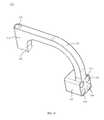
- FIG. 1is a top perspective view of a step off bone plate, in accordance with an aspect of the present invention
- FIG. 2is a bottom perspective view of the step off bone plate of FIG. 1 , in accordance with an aspect of the present invention
- FIG. 3a first side view of the step off bone plate of FIG. 1 , in accordance with an aspect of the present invention
- FIG. 4is a second side view of the step off bone plate of FIG. 1 , in accordance with an aspect of the present invention.
- FIG. 5is a front view of the step off bone plate of FIG. 1 , in accordance with an aspect of the present invention.
- FIG. 6is a back view of the step off bone plate of FIG. 1 , in accordance with an aspect of the present invention.
- FIG. 7is a top view of the step off bone plate of FIG. 1 , in accordance with an aspect of the present invention.
- FIG. 8is a bottom view of the step off bone plate of FIG. 1 , in accordance with an aspect of the present invention.
- FIG. 9is a top perspective view of another step off bone plate, in accordance with an aspect of the present invention.
- FIG. 10is a bottom perspective view of the step off bone plate of FIG. 9 , in accordance with an aspect of the present invention.
- FIG. 11a first side view of the step off bone plate of FIG. 9 , in accordance with an aspect of the present invention.
- FIG. 12is a second side view of the step off bone plate of FIG. 9 , in accordance with an aspect of the present invention.
- FIG. 13is a front view of the step off bone plate of FIG. 9 , in accordance with an aspect of the present invention.
- FIG. 14is a back view of the step off bone plate of FIG. 9 , in accordance with an aspect of the present invention.
- FIG. 15is a top view of the step off bone plate of FIG. 9 , in accordance with an aspect of the present invention.
- FIG. 16is a bottom view of the step off bone plate of FIG. 9 , in accordance with an aspect of the present invention.
- FIG. 17is a perspective view of a bone plate alignment guide apparatus, in accordance with an aspect of the present invention.
- FIG. 18is a side view of the bone plate alignment guide apparatus of FIG. 17 , in accordance with an aspect of the present invention.
- FIG. 19is an exploded side view of the bone plate alignment guide apparatus of FIG. 17 , in accordance with an aspect of the present invention.
- FIG. 20is a bottom perspective view of the body of the bone plate alignment guide apparatus of FIG. 17 , in accordance with an aspect of the present invention.
- FIG. 21is an end perspective view of the body of the bone plate alignment guide apparatus of FIG. 17 , in accordance with an aspect of the present invention.
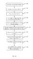
- FIG. 22depicts one embodiment of a method for using the step off bone plate, in accordance with an aspect of the present invention.
- step off bone plateGenerally stated, disclosed herein is an embodiment of a step off bone plate.
- the terms “step off bone plate,” “bone plate,” and “plate”may be used interchangeably herein as they essentially refer to the same device. Further, a method for using the step off bone plate is discussed.
- proximal, distal, anterior, posterior, medial, lateral, superior, inferior, dorsal and plantarare defined by their standard usage for indicating a particular part of a bone or implant according to the relative disposition of the natural bone or directional terms of reference.
- proximalmeans the portion of an implant nearest the torso
- distalindicates the portion of the implant farthest from the torso.
- anterioris a direction towards the front side of the body
- posteriormeans a direction towards the back side of the body
- medialmeans towards the midline of the body
- lateralis a direction towards the sides or away from the midline of the body
- superiormeans a direction above and “inferior” means a direction below another object or structure.
- the term “dorsal”refers to the top of the foot and the term “plantar” refers the bottom of the foot.
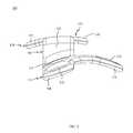
- a bone plate 100for example, a step off bone plate, is shown.
- the bone plate 100is designed for medial wall positioning to provide a bone plate 100 with a dual curvature along the long axis of the plate 100 to match the correction of a more dorsally located plate.
- the dual curvatures of the plate 100allow for the plate 100 to be positioned medially thereby providing a more stable construct and a plate that resists bending.
- the step off bone plate 100includes a body 102 with a first end 104 , a second end 106 , and a transition point 108 positioned between the first end 104 and the second end 106 .
- the body 102may include a first portion 110 , a second portion 120 , and a connecting portion 140 coupling the first portion 110 to the second portion 120 .
- the first portion 110may extend from the first end 104 to the transition point 108 .
- the second portion 120may extend from the transition point 108 to the second end 106 .
- the connecting portion 140may be positioned between the first portion 110 and second portion 120 at the transition point 108 .
- the first portion 110may have at least one slot 112 near the first end 104 of the body 102 and at least one first opening 114 positioned between the at least one slot 112 and the transition point 108 .
- the at least one first opening 114may be positioned adjacent to the at least one slot 112 .
- the slot 112 and first opening 114may be, for example, aligned along the center of the body 102 .
- the opening 114may be, for example, a screw hole for receiving a threaded fastener or screw (not shown).
- the first portion 110may also include an extension member or arm 116 , as shown in FIGS. 1-3 and 5-8 .
- the extension member 116may extend out from a side of the body 102 of the first portion 110 and may include at least one second opening 118 .
- the extension member 116may extend out from the body between the first end 104 and the transition point 108 and may be angled with respect to the longitudinal axis of the body 102 .
- the extension member 116may extend out from the body near the first opening 114 .
- the extension member 116may be angled toward the second end 106 of the body 102 .
- the extension member 116may also be curved as it extends away from the body 102 as seen in FIG. 5 .
- the curvature of the extension member 116may, for example, match the curvature of the bone engaging the first portion 110 .
- the extension member 116may be configured to reinforce the plantar aspect of the foot to reduce or restrict gapping after surgery by providing plantar support from a medial positioned plate 100 .
- the extension member 116may also be positioned in the direction that matches the normal transition of stress during the gait cycle to provide the greatest strength during peak loads.
- the first portion 110 of the plate 100may include a dual curvature with, for example, a first curvature perpendicular to the long axis of the plate 100 and a second curvature along the long axis of the plate 100 .
- the first curvaturemay have a radius of, for example, approximately 8 mm to 60 mm
- the second curvaturemay have a radius of, for example, approximately 50 mm to 300 mm.
- the second portion 120may include a first lobe 122 and a second lobe 126 extending out from the body 102 .
- the first lobe 122may be offset from the second lobe 126 forming an angled surface at the second end 106 of the body 102 as seen in FIG. 5 .
- the first lobe 122may include a third opening 124 and the second lobe 124 may include a fourth opening 128 .
- Alternative numbers of lobes 122 , 126are also contemplated to provide for additional fastening locations for securing the plate 100 to the patient's bones.
- the openings 124 , 128may be, for example, screw holes for receiving threaded fasteners or screws (not shown).
- the second portion 120may also include a ramped portion 130 positioned at the second end 106 along the angled surface.
- the ramped portion 130is gradually angled from the bottom surface to the top surface of the body 102 and provides a surface that allows a tendon, for example, the anterior tibialis tendon, to glide over the plate 100 . By allowing the tendon to glide over the plate soft-tissue irritation is eliminated. Existing plate designs cause the tendon to pop or jump over the plate resulting in patient discomfort.
- the ramped portion 130may decrease the thickness of the plate at the second end 106 , while still maintaining adequate thickness to prevent screw prominence.
- the connecting portion 140is positioned relatively perpendicular to and couples the first portion 110 and the second portion 120 .
- the connecting portion 140provides a change in elevation or “step up” from the first portion 110 to the second portion 120 .
- the connecting portion 140may provide a step up of, for example, approximately 1 mm to 10 mm.
- the connecting portion 140may include a sloped surface 142 on the top of the body 102 .
- the connecting portion 140may include a first transition portion 144 extending from the first portion 110 to the transition point 108 and a second transition portion 146 extending perpendicular to the first transition portion 144 from the transition point 108 to the second portion 120 .
- the first transition portion 144 and second transition portion 146may be relatively planar.
- the plate 100may include multiple curved surfaces.
- the plate 100may include dual curvatures with respect to the longitudinal axis of the plate 100 , as shown in FIGS. 5-6 .
- the first portion 110may have a first curvature in a medial-lateral direction with respect to the longitudinal axis of the plate 100 .
- the first curvaturemay have a range of, for example, approximately 8 mm to 60 mm.
- the second portion 120may have a second curvature in the medial-lateral direction along with respect to the longitudinal axis of the plate 100 along the bottom surface.
- the second curvaturemay have a range from, for example, approximately 10 mm to 60 mm.
- the first curvature and second curvaturemay be different in plate 100 to allow for the plate 100 to be used on the medial aspect of a patient's foot.
- the body 102 of the plate 100may have a third curvature in line with the longitudinal axis and the third curvature may have a range of, for example, approximately 50 mm to 300 mm.
- the bone plate 200may include a body 202 with a first end 204 , a second end 206 , and a transition point 208 positioned between the first end 204 and the second end 206 .
- the body 202may include a first portion 210 , a second portion 220 , and a connecting portion 240 attaching the first portion 210 to the second portion 220 .
- the first portion 210may extend from the first end 204 to the transition point 208 .
- the second portion 220may extend from the transition point 208 to the second end 206 .
- the connecting portion 240may be positioned between the first portion 210 and second portion 220 at the transition point 208 .
- the first portion 210may have at least one slot 212 near the first end 204 of the body 202 , at least one first opening 214 positioned adjacent the at least one slot 212 , and at least one channel 232 positioned between the at least one first opening 214 and the transition point 208 .
- the at least one channel 232may be positioned adjacent to the at least one slot 212 .
- the slot 212 , first opening 214 , and channel 232may be, for example, aligned along the center of the body 202 .
- the slot 212may be, for example, a compression screw hole for receiving a threaded fastener or screw (not shown).
- the opening 214may be, for example, a screw hole for receiving a threaded fastener or screw (not shown).
- the channel 232may be, for example, an opening for receiving an insertion tool.
- the first portion 210may also include an extension member or arm 216 , as shown in FIGS. 9-11 and 13-16 .
- the extension member 216may extend out from a side of the body 202 of the first portion 210 and may include at least one second opening 218 .
- the extension member 216may extend out from the body between the first end 204 and the transition point 208 and may be angled with respect to the longitudinal axis of the body 202 .
- the extension member 216may extend out from the body near the first opening 214 and channel 232 .
- the extension member 216may be angled toward the second end 206 of the body 202 .
- the extension member 216may also be curved as it extends away from the body 202 as seen in FIG. 13 .
- the curvature of the extension member 216may, for example, match the curvature of the bone engaging the first portion 210 .
- the extension member 216may be configured to reinforce the plantar aspect of the foot to reduce or restrict gapping after surgery by providing plantar support from a medial positioned plate 200 .
- the extension member 216may also be positioned in the direction that matches the normal transition of forces during the gait cycle to provide the greatest strength during peak loads.
- the extension member 216may be shorter than the extension member 116 .
- the extension member 216may be positioned closer to the transition point 208 than the extension member 116 is positioned to the transition point 108 .
- the first portion 210 of the plate 200may include a dual curvature with, for example, a first curvature perpendicular to the long axis of the plate 200 and a second curvature along the long axis of the plate 200 .
- the first curvaturemay have a radius of, for example, approximately 8 mm to 60 mm
- the second curvaturemay have a radius of, for example, approximately 50 mm to 300 mm.
- the first portion 210 near the first end 204 and including the slot 212may be angled relative to the second curvature, as shown in FIGS. 11 and 12 .
- the second portion 220may include a first lobe 222 and a second lobe 226 extending out from the body 202 .
- the first lobe 222may be offset from the second lobe 226 forming an angled surface at the second end 206 of the body 202 as seen in FIG. 15 .
- the first lobe 222may include a third opening 224 and the second lobe 224 may include a fourth opening 228 .
- Alternative numbers of lobes 222 , 226are also contemplated to provide for additional fastening locations for securing the plate 200 to the patient's bones.
- the openings 224 , 228may be, for example, screw holes for receiving threaded fasteners or screws (not shown).
- the second portion 220may also include a ramped portion 230 positioned at the second end 206 along the angled surface.
- the ramped portion 230is gradually angled from the bottom surface to the top surface of the body 202 and provides a surface that allows a tendon, for example, the anterior tibialis tendon, to glide over the plate 200 .
- the ramped portion 230has a more pronounced angle than the ramped portion 130 . As discussed in greater detail above with respect to ramped portion 130 , by allowing the tendon to glide over the plate soft-tissue irritation is eliminated.
- the ramped portion 230may decrease the thickness of the plate at the second end 206 , while still maintaining adequate thickness to prevent screw prominence.
- the connecting portion 240is positioned relatively perpendicular to and couples the first portion 210 and the second portion 220 .
- the connecting portion 240provides a change in elevation or “step up” from the first portion 210 to the second portion 220 .
- the connecting portion 240may provide a step up of, for example, approximately 1 mm to 10 mm.
- the connecting portion 240may include a sloped surface 242 on the top of the body 202 .
- the connecting portion 240may include a first transition portion 244 extending from the first portion 210 to the transition point 208 and a second transition portion 246 extending perpendicular to the first transition portion 244 from the transition point 208 to the second portion 220 .
- the first transition portion 244 and second transition portion 246may be relatively planar.
- the plate 200may include multiple curved surfaces.
- the plate 200may include dual curvatures with respect to the longitudinal axis of the plate 200 , as shown in FIGS. 13-14 .
- the first portion 210may have a first curvature in a medial-lateral direction with respect to the longitudinal axis of the plate 200 .
- the first curvaturemay have a range of, for example, approximately 8 mm to 60 mm.
- the second portion 220may have a second curvature in the medial-lateral direction along with respect to the longitudinal axis of the plate 200 along the bottom surface.
- the second curvaturemay have a range from, for example, approximately 10 mm to 60 mm.
- the first curvature and second curvaturemay be different in plate 200 to allow for the plate 200 to be used on the medial aspect of a patient's foot.
- the body 202 of the plate 200may have a third curvature along a portion of the plate 200 in line with the longitudinal axis and the third curvature may have a range of, for example, approximately 50 mm to 300 mm.
- the first end 204 of the plate 200may not be curved along the longitudinal axis of the plate.
- the plate curvaturesmay have radii that are positioned off axis to provide strength to the plates 100 , 200 and to enable placement of the plates 100 , 200 on the medial aspect of the patient's bone.
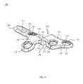
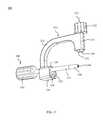
- the bone plate alignment guide apparatus 300may include a body 310 , a coupling member 330 , a guide pin tissue protector 340 .
- the apparatus 300may also include a guide wire or pin (not shown) and a fastener (not shown).
- the coupling member 330may include a knob 332 and a shaft 334 .
- the shaft portion 334may include an engagement portion 336 for coupling to a bone plate, for example, bone plate 100 or 200 , and a groove 338 which may assist with coupling the engagement portion 336 to a bone plate.
- the engagement portion 336may be, for example, threaded to engage corresponding threads in an opening in a bone plate, deformable to be removeably press fit into the opening in the bone plate, or another similar configuration that achieves a coupling of the guide apparatus 300 to a bone plate, such as, bone plate 100 , 200 , or the like.
- the guide wire(not shown) may be, for example, a pin, k-wire, olive wire, or the like.
- the fastener(not shown) may be, for example, a compression screw, lag screw, headless screw, or a solid screw, for crossing a joint or fracture.
- the guide pin tissue protector 340may include a handle portion 342 at a first end and a shaft portion 344 extending away from the handle portion 342 to a tip 348 at a second end.
- the shaft 344may taper at the second end to form the tip 348 .
- the guide pin tissue protector 340may also include a through hole 346 extending from the first end to the second end to enable a guide wire (not shown) to pass through the tissue protector 340 and engage the patient's bone.
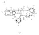
- the body 310may include an arm 312 with an attachment portion 314 at a first end and an alignment portion 316 at a second end.
- the alignment portion 316 of the body 310may be, for example, a variable hole alignment portion, and may include a plurality of holes 318 .
- the plurality of holes 318may be, for example four holes that are positioned in a square arrangement.
- the plurality of holes 318may be straight or angled to a desired insertion position relative to the arm 312 of the body 310 .
- the two left holes and two right holesmay, for example, each be slightly angled toward the center of the alignment portion 316 such that each of the side holes converge toward each other.
- the top two holes and the bottom two holesmay each be slightly angled toward the center of the alignment portion 316 such that each of the holes converge toward each other.
- Alternative angled arrangements for the holes 318are also contemplated to enable a fastener to be inserted across two bones into a position that will not be in the path of the bone plate screws when they are inserted.
- the body 310may also include a through hole 320 in the attachment portion 314 of the body 310 , as seen in FIGS. 20-21 .
- the body 310may include an alignment protrusion 322 extending away from the attachment portion 314 , as shown in FIGS. 17-20 , for engaging an opening in a bone plate, such as bone plate 100 , 200 , or the like.
- the alignment protrusion 322may be used to position the bone plate alignment guide apparatus 300 with respect to a bone plate.
- the alignment guide 300may be used with plates 100 and 200 .
- the alignment guide 300 and plate 100 or 200form a bone plate insertion system that allows for the insertion of a crossing fastener and the bone plate screws without either contacting the other.
- the bone plate insertion systemsprovide a surgeon the ability to precisely place the crossing fastener and bone plate screws without the need for additional imaging or trial and error, thereby improving the surgical procedure.
- the methodmay include preparing the patient's bones 400 and aligning the patient's bones 410 .
- the methodmay include selecting a bone plate 420 and attaching an insertion guide to the bone plate 430 .
- the bone platemay be aligned on the patient's bones 440 .
- the bone platemay be secured to the patient's bones with temporary fixation members 450 .
- a guide wiremay be inserted across the patient's joint 460 and the insertion guide may then be removed from the bone plate 470 .
- the guide wiremay be used to insert a screw across the joint 380 .
- the screwsmay be inserted to secure the plate to the bones and the temporary fixation members removed 490 .
- the method as shown in FIG. 22may be described in greater detail with reference to FIGS. 1-21 .
- the surgeonwill prepare the patient's bones by selecting the cartilage removal technique, for example, curettage or sagittal saw blade. If the surgeon selects to use a curettage, then the correction method will be translation of the bone, for example, the metatarsal. However, if the surgeon selects to use a sagittal saw blade, then the correction method will be angular correction of the joint, for example, the tarso-metatarsal joint.
- the bonesOnce the bones are prepared, they will be aligned for fixation and a guide wire may be inserted to temporarily stabilize the joint.
- a bone plate alignment guide apparatus 300may be secured to the selected bone plate 100 , 200 .
- the apparatus 300may be secured by aligning the alignment protrusion 322 of the guide 300 with an opening (not shown) in the plate 100 , 200 and inserting coupling member 330 through the opening 320 in the body 310 and securing the engagement portion 336 to another opening in the plate 100 , 200 .
- the plate 100 , 200may be aligned onto the patient's bones.
- the plate 100 , 200is aligned with the long axis of the plate 100 , 200 being parallel to the long axis of the bone, for example, metatarsal bone, to ensure proper orientation of the guide 300 .
- the plate 100 , 200is secured to the bones using at least two temporary fixation members, for example, olive wires.
- the first temporary fixation membermay be inserted into the proximal screw hole in the plate 100 , 200 and the second into a second opening in the plate 100 , 200 .
- the first temporary fixation membermay be inserted into openings 124 , 128 or 224 , 228 and the second temporary fixation member may be inserted into the slot 112 , 212 .
- the guide pin tissue protector 340may be inserted into one of the through holes 318 in the body 310 .
- a guide wiremay be inserted through the hole 346 and across the joint. Once the guide wire is determined to be in the correct position, the protector 340 may be removed from the body 310 and the coupling member 330 may be disengaged from the bone plate 100 , 200 and the coupling member 330 and body 310 removed from the bone plate 100 , 200 .
- a screw insertion technique for inserting a crossing fastenerfor example, a compression lag screw, may be employed to insert the crossing fastener through the joint.
- the crossing fasteneris preferably inserted over the guide wire to obtain proper positioning to avoid contact with the bone plate screws when they are later inserted.
- the guide wiremay be removed.
- screws(not shown) may be inserted into the patient's bones through the bone plate 100 , 200 .
- the screwsmay be inserted by, for example, using a threaded drill guide to drill the openings for the screws, then the openings are measured, and finally the screws are inserted into the openings.
- the screwsmay be, for example, locking screws, non-locking screws, or a combination thereof.
- the screwswill be inserted without contacting the crossing fastener because the guide 300 correctly positions the crossing fastener such that it is not in the path of any of the bone plate screw openings.
- a method or device that “comprises,” “has,” “includes,” or “contains” one or more steps or elementspossesses those one or more steps or elements, but is not limited to possessing only those one or more steps or elements.
- a step of a method or an element of a device that “comprises,” “has,” “includes,” or “contains” one or more featurespossesses those one or more features, but is not limited to possessing only those one or more features.
- a device or structure that is configured in a certain wayis configured in at least that way, but may also be configured in ways that are not listed.
Landscapes
- Health & Medical Sciences (AREA)
- Orthopedic Medicine & Surgery (AREA)
- Surgery (AREA)
- Life Sciences & Earth Sciences (AREA)
- Heart & Thoracic Surgery (AREA)
- Veterinary Medicine (AREA)
- Engineering & Computer Science (AREA)
- Biomedical Technology (AREA)
- Nuclear Medicine, Radiotherapy & Molecular Imaging (AREA)
- Medical Informatics (AREA)
- Molecular Biology (AREA)
- Animal Behavior & Ethology (AREA)
- General Health & Medical Sciences (AREA)
- Public Health (AREA)
- Neurology (AREA)
- Dentistry (AREA)
- Oral & Maxillofacial Surgery (AREA)
- Surgical Instruments (AREA)
Abstract
Description
Claims (19)
Priority Applications (3)
| Application Number | Priority Date | Filing Date | Title |
|---|---|---|---|
| US14/547,616US9980760B2 (en) | 2014-11-19 | 2014-11-19 | Step off bone plates, systems, and methods of use |
| ES15195121TES2869344T3 (en) | 2014-11-19 | 2015-11-18 | Bone Plates, Plate Alignment Systems, and Methods of Use |
| EP15195121.7AEP3023068B1 (en) | 2014-11-19 | 2015-11-18 | Bone plates, plate alignment systems, and methods of use |
Applications Claiming Priority (1)
| Application Number | Priority Date | Filing Date | Title |
|---|---|---|---|
| US14/547,616US9980760B2 (en) | 2014-11-19 | 2014-11-19 | Step off bone plates, systems, and methods of use |
Publications (2)
| Publication Number | Publication Date |
|---|---|
| US20160135858A1 US20160135858A1 (en) | 2016-05-19 |
| US9980760B2true US9980760B2 (en) | 2018-05-29 |
Family
ID=54548109
Family Applications (1)
| Application Number | Title | Priority Date | Filing Date |
|---|---|---|---|
| US14/547,616Active2036-10-07US9980760B2 (en) | 2014-11-19 | 2014-11-19 | Step off bone plates, systems, and methods of use |
Country Status (3)
| Country | Link |
|---|---|
| US (1) | US9980760B2 (en) |
| EP (1) | EP3023068B1 (en) |
| ES (1) | ES2869344T3 (en) |
Cited By (35)
| Publication number | Priority date | Publication date | Assignee | Title |
|---|---|---|---|---|
| US20180049787A1 (en)* | 2016-08-17 | 2018-02-22 | Globus Medical, Inc. | Volar distal radius stabilization system |
| US11497528B2 (en) | 2014-07-15 | 2022-11-15 | Treace Medical Concepts, Inc. | Bone positioning and cutting system and method |
| US11583323B2 (en) | 2018-07-12 | 2023-02-21 | Treace Medical Concepts, Inc. | Multi-diameter bone pin for installing and aligning bone fixation plate while minimizing bone damage |
| US11596443B2 (en) | 2018-07-11 | 2023-03-07 | Treace Medical Concepts, Inc. | Compressor-distractor for angularly realigning bone portions |
| US11602386B2 (en) | 2015-07-14 | 2023-03-14 | Treace Medical Concepts, Inc. | Bone positioning guide |
| US11602387B2 (en) | 2015-08-14 | 2023-03-14 | Treace Medical Concepts, Inc. | Bone positioning and preparing guide systems and methods |
| US11607250B2 (en) | 2019-02-13 | 2023-03-21 | Treace Medical Concepts, Inc. | Tarsal-metatarsal joint procedure utilizing compressor-distractor and instrument providing sliding surface |
| US11622797B2 (en) | 2020-01-31 | 2023-04-11 | Treace Medical Concepts, Inc. | Metatarsophalangeal joint preparation and metatarsal realignment for fusion |
| US11627954B2 (en) | 2019-08-07 | 2023-04-18 | Treace Medical Concepts, Inc. | Bi-planar instrument for bone cutting and joint realignment procedure |
| US11648019B2 (en) | 2015-09-18 | 2023-05-16 | Treace Medical Concepts, Inc. | Joint spacer systems and methods |
| US11690659B2 (en) | 2015-08-14 | 2023-07-04 | Treace Medical Concepts, Inc. | Tarsal-metatarsal joint procedure utilizing fulcrum |
| US11786257B2 (en) | 2015-01-07 | 2023-10-17 | Treace Medical Concepts, Inc. | Bone cutting guide systems and methods |
| US11844533B2 (en) | 2015-02-18 | 2023-12-19 | Treace Medical Concepts, Inc. | Pivotable bone cutting guide useful for bone realignment and compression techniques |
| USD1011524S1 (en) | 2022-02-23 | 2024-01-16 | Treace Medical Concepts, Inc. | Compressor-distractor for the foot |
| US11889998B1 (en) | 2019-09-12 | 2024-02-06 | Treace Medical Concepts, Inc. | Surgical pin positioning lock |
| US11890039B1 (en) | 2019-09-13 | 2024-02-06 | Treace Medical Concepts, Inc. | Multi-diameter K-wire for orthopedic applications |
| EP4319663A1 (en) | 2021-04-09 | 2024-02-14 | Paragon 28, Inc. | Surgical instruments, guides, and methods of use |
| US11931106B2 (en) | 2019-09-13 | 2024-03-19 | Treace Medical Concepts, Inc. | Patient-specific surgical methods and instrumentation |
| US11931047B2 (en) | 2016-08-26 | 2024-03-19 | Treace Medical Concepts, Inc. | Osteotomy procedure for correcting bone misalignment |
| US11963703B2 (en) | 2015-07-14 | 2024-04-23 | Treace Medical Concepts, Inc. | Bone cutting guide systems and methods |
| US11969193B2 (en) | 2015-05-06 | 2024-04-30 | Treace Medical Concepts, Inc. | Intra-osseous plate system and method |
| US11986251B2 (en) | 2019-09-13 | 2024-05-21 | Treace Medical Concepts, Inc. | Patient-specific osteotomy instrumentation |
| US12004789B2 (en) | 2020-05-19 | 2024-06-11 | Treace Medical Concepts, Inc. | Devices and techniques for treating metatarsus adductus |
| USD1051382S1 (en) | 2022-02-23 | 2024-11-12 | Treace Medical Concepts, Inc. | Lesser metatarsal cut guide |
| US12161371B2 (en) | 2021-01-18 | 2024-12-10 | Treace Medical Concepts, Inc. | Contoured bone plate with locking screw for bone compression, particularly across a tarsometatarsal joint |
| USD1057155S1 (en) | 2022-02-23 | 2025-01-07 | Treace Medical Concepts, Inc. | Lesser metatarsal cut guide with parallel cut faces |
| US12193683B2 (en) | 2021-05-20 | 2025-01-14 | Treace Medical Concepts, Inc. | Cut guide with integrated joint realignment features |
| USD1068078S1 (en) | 2023-02-08 | 2025-03-25 | Treace Medical Concepts, Inc. | Handle for an orthopedic instrument |
| USD1068077S1 (en) | 2023-02-08 | 2025-03-25 | Treace Medical Concepts, Inc. | Orthopedic rasp for preparing an intercuneiform joint |
| USD1075012S1 (en) | 2022-02-23 | 2025-05-13 | Treace Medical Concepts, Inc. | Metatarsal lateral release instrument |
| US12310603B2 (en) | 2021-02-18 | 2025-05-27 | Treace Medical Concepts, Inc. | System and technique for metatarsal realignment with reduced incision length |
| USD1079011S1 (en) | 2022-02-23 | 2025-06-10 | Treace Medical Concepts, Inc. | Metatarsal cut guide with parallel cut faces |
| US12357347B2 (en) | 2017-02-26 | 2025-07-15 | Treace Medical Concepts, Inc. | Fulcrum for tarsal-metatarsal joint procedure |
| US12414779B2 (en) | 2016-11-11 | 2025-09-16 | Treace Medical Concepts, Inc. | Devices and techniques for performing an osteotomy procedure on a first metatarsal to correct a bone misalignment |
| US12440250B2 (en) | 2024-02-05 | 2025-10-14 | Treace Medical Concepts, Inc. | Multi-diameter K-wire for orthopedic applications |
Families Citing this family (21)
| Publication number | Priority date | Publication date | Assignee | Title |
|---|---|---|---|---|
| EP4252686A3 (en) | 2012-12-28 | 2023-12-27 | Paragon 28, Inc. | Alignment guide apparatus |
| US20150335365A1 (en)* | 2014-05-24 | 2015-11-26 | Neutin Orthopedics, LLC | Fixation device for a mau-type osteotomy procedure |
| CN105943149B (en)* | 2016-06-02 | 2019-04-02 | 北京德益达美医疗科技有限公司 | A kind of fixed system of Distal tibiofibular diastasis |
| EP3528716B1 (en) | 2016-10-24 | 2024-02-14 | Paragon 28, Inc. | Osteotomy systems |
| ES2993743T3 (en) | 2017-02-27 | 2025-01-08 | Paragon 28 Inc | Targeting instruments and systems |
| EP3585287B1 (en)* | 2017-02-27 | 2024-11-13 | Paragon 28, Inc. | Intramedullary nail fixation systems |
| US10918431B2 (en) | 2017-03-30 | 2021-02-16 | Paragon 28, Inc. | Bone fixation system, assembly, implants, devices, alignment guides, and methods of use |
| EP3651699B1 (en) | 2017-07-11 | 2025-09-17 | Paragon 28, Inc. | Bone fixation system, assembly, implants, devices and insertion guides |
| ES2971443T3 (en)* | 2017-12-08 | 2024-06-05 | Paragon 28 Inc | Bone fixation and implant set |
| EP3820382B1 (en) | 2018-07-11 | 2025-09-10 | Paragon 28, Inc. | Systems comprising alignment guides and implants |
| EP3923842A4 (en) | 2019-02-13 | 2022-11-23 | Paragon 28, Inc. | IMPLANTS, ALIGNMENT GUIDES, SYSTEMS AND METHODS OF USE |
| JP7562547B2 (en) | 2019-02-14 | 2024-10-07 | パラゴン28・インコーポレイテッド | Threaded targeting instruments, systems, and methods of use |
| AU2020228309B2 (en) | 2019-02-28 | 2025-10-02 | Paragon 28, Inc. | Fusion systems, instruments, bone plates and methods of use |
| WO2021021640A1 (en) | 2019-07-26 | 2021-02-04 | Crossroads Extremity Systems, Llc | Bone repositioning guide system and procedure |
| USD945623S1 (en)* | 2019-09-20 | 2022-03-08 | New Generation Devices, Inc. | Tibial plate |
| US12295629B2 (en)* | 2019-09-20 | 2025-05-13 | Movora, Llc | Tibial plateau leveling osteotomy plate with offset |
| US12213710B2 (en) | 2019-09-20 | 2025-02-04 | Movora, Llc | Tibial plateau leveling osteotomy plate with offset |
| USD931462S1 (en)* | 2020-03-11 | 2021-09-21 | DePuy Synthes Products, Inc. | Bone plate |
| USD931461S1 (en)* | 2020-03-11 | 2021-09-21 | DePuy Synthes Products, Inc. | Bone plate |
| USD1018854S1 (en)* | 2020-09-21 | 2024-03-19 | Movora, Llc | Tibial plate |
| CN114176750A (en)* | 2021-12-08 | 2022-03-15 | 重庆熙科医疗科技有限公司 | Dorsal correction plate for first metatarsal distal Scarf osteotomy |
Citations (40)
| Publication number | Priority date | Publication date | Assignee | Title |
|---|---|---|---|---|
| JPH04250156A (en) | 1990-07-23 | 1992-09-07 | Synthes Ag | Bone joint plate |
| WO1994015556A1 (en) | 1993-01-15 | 1994-07-21 | Depuy Inc. | Drill guide apparatus and method |
| EP0617927A1 (en) | 1993-03-28 | 1994-10-05 | Yehiel Gotfried | Surgical device for connection of fractured bones |
| FR2706763A1 (en) | 1993-06-25 | 1994-12-30 | Implants Ind Sa | Osteosynthesis plate |
| US6342057B1 (en) | 2000-04-28 | 2002-01-29 | Synthes (Usa) | Remotely aligned surgical drill guide |
| EP1273271A2 (en) | 2001-07-02 | 2003-01-08 | Aesculap AG & Co. KG | Surgical instrument |
| US6692496B1 (en) | 1998-11-02 | 2004-02-17 | Grampian University Hospitals Nhs Trust | Fracture treatment |
| US20050033301A1 (en) | 2002-05-15 | 2005-02-10 | Guiseppe Lombardo | Cross-pin graft fixation, instruments, and methods |
| US7011665B2 (en) | 2002-07-22 | 2006-03-14 | Sdgi Holdings, Inc. | Guide assembly for engaging a bone plate to a bony segment |
| US20060189996A1 (en) | 2005-01-28 | 2006-08-24 | Orbay Jorge L | Nail plate and implantation jig therefor |
| US20070173843A1 (en)* | 2005-12-22 | 2007-07-26 | Matityahu Amir M | Drug delivering bone plate and method and targeting device for use therewith |
| US20070225714A1 (en) | 2003-10-18 | 2007-09-27 | Georg Gradl | System for the Minimally Invasive Treatment of a Bone Fracture, Especially of a Proximal Humeral or Femoral Fracture |
| US20070239168A1 (en) | 2004-02-20 | 2007-10-11 | Thomas Kuenzi | Aiming Device for Inserting Angle-Stable, Long Screws in the Articular Region of a Bone |
| US20080021452A1 (en) | 2006-07-18 | 2008-01-24 | Dustin Ducharme | Calcaneal plate |
| EP1897509A1 (en) | 2006-09-11 | 2008-03-12 | Surge Foot | Arthrodesis plate for a metatarsal-phalanges joint |
| US20090036931A1 (en) | 2007-08-04 | 2009-02-05 | Normed Medizin-Technik Vertriebs-Gmbh | Foot surgery bone plate, and system comprising bone plate and insertion aid |
| CN201223440Y (en) | 2008-07-17 | 2009-04-22 | 傅宏 | Three-dimensional dissection type anterior steel plate for acetabulum |
| DE102007047576A1 (en) | 2007-10-04 | 2009-04-23 | Normed Medizin-Technik Vertriebs-Gmbh | Foot bone plate i.e. lapidus plate, for treatment of hallus valgus, has longitudinal center axis of passage opening arranged at axis, where axis extends in attachment sections along longitudinal extension of contact surface |
| WO2009105201A1 (en) | 2008-02-19 | 2009-08-27 | Orthohelix Surgical Designs, Inc. | Orthopedic plates for use in the midfoot |
| CN201365972Y (en) | 2009-03-12 | 2009-12-23 | 占开喜 | Tibial plateau back-side dissection bone fracture plate |
| US20100087824A1 (en) | 2008-10-03 | 2010-04-08 | Howmedica Osteonics Corp. | High tibial osteotomy instrumentation |
| WO2010059497A1 (en) | 2008-11-19 | 2010-05-27 | Amei Technologies, Inc. | Fixation plate for use in the lapidus approach |
| US7819877B2 (en) | 2001-06-27 | 2010-10-26 | BePuy Products, Inc. | Method and apparatus for endoscopic minimally invasive orthopaedic plating procedures |
| US20110218576A1 (en) | 2009-11-27 | 2011-09-08 | Andre Galm | Plating Concept for Distal Radial Fractures |
| US20110264149A1 (en) | 2010-04-27 | 2011-10-27 | Dana Pappalardo | Bone fixation system including k-wire compression |
| US8080010B2 (en)* | 2004-03-25 | 2011-12-20 | Greatbatch Medical S.A. | Device and template for canine humeral slide osteotomy |
| US20120078252A1 (en) | 2010-09-27 | 2012-03-29 | Huebner Randall J | Targeting guide with a radiopaque marker to facilitate positioning a bone plate on bone |
| CN202218914U (en) | 2011-08-28 | 2012-05-16 | 泰州市中兴医械科技有限公司 | Minimally invasive femoral neck and intertrochanteric comminuted fracture rear side pressurization bone fracture plate |
| US8231627B2 (en) | 2007-07-19 | 2012-07-31 | Acumed Llc | Insertion tool for bone plates |
| US20120303038A1 (en) | 2011-05-25 | 2012-11-29 | Oliviero Durante | Aiming device having radio-opaque markers |
| CN203417254U (en) | 2013-07-16 | 2014-02-05 | 江苏双羊医疗器械有限公司 | Anatomical type locking calcaneus bone fracture plate |
| US20140148859A1 (en) | 2012-11-27 | 2014-05-29 | Solana Surgical, Llc | Orthopedic fusion plate and compression screw |
| US20140180348A1 (en) | 2012-12-21 | 2014-06-26 | Wright Medical Technology, Inc. | Trajectory guide |
| US8764807B2 (en) | 2010-06-10 | 2014-07-01 | Arthrex, Inc. | Calcaneus step plate |
| WO2014105750A1 (en) | 2012-12-28 | 2014-07-03 | Paragon 28, Inc. | Alignment guide apparatus, method and system |
| EP2762098A2 (en) | 2009-04-28 | 2014-08-06 | Osteomed Llc | Bone plate with a transfixation screw hole |
| WO2014140886A2 (en) | 2013-03-15 | 2014-09-18 | Merete Medical Gmbh | Fixation device and method of use for a lapidus-type plantar hallux valgus procedure |
| US20140309703A1 (en) | 2005-01-28 | 2014-10-16 | Orthohelix Surgical Designs, Inc. | Orthopedic plates for use in clavicle repair and methods for their use |
| WO2015094409A1 (en) | 2013-12-20 | 2015-06-25 | Paragon 28, Inc. | Alignment guide apparatus, methods and systems |
| US9283008B2 (en)* | 2012-12-17 | 2016-03-15 | Toby Orthopaedics, Inc. | Bone plate for plate osteosynthesis and method for use thereof |
- 2014
- 2014-11-19USUS14/547,616patent/US9980760B2/enactiveActive
- 2015
- 2015-11-18EPEP15195121.7Apatent/EP3023068B1/enactiveActive
- 2015-11-18ESES15195121Tpatent/ES2869344T3/enactiveActive
Patent Citations (41)
| Publication number | Priority date | Publication date | Assignee | Title |
|---|---|---|---|---|
| JPH04250156A (en) | 1990-07-23 | 1992-09-07 | Synthes Ag | Bone joint plate |
| WO1994015556A1 (en) | 1993-01-15 | 1994-07-21 | Depuy Inc. | Drill guide apparatus and method |
| EP0617927A1 (en) | 1993-03-28 | 1994-10-05 | Yehiel Gotfried | Surgical device for connection of fractured bones |
| FR2706763A1 (en) | 1993-06-25 | 1994-12-30 | Implants Ind Sa | Osteosynthesis plate |
| US6692496B1 (en) | 1998-11-02 | 2004-02-17 | Grampian University Hospitals Nhs Trust | Fracture treatment |
| US6342057B1 (en) | 2000-04-28 | 2002-01-29 | Synthes (Usa) | Remotely aligned surgical drill guide |
| US7819877B2 (en) | 2001-06-27 | 2010-10-26 | BePuy Products, Inc. | Method and apparatus for endoscopic minimally invasive orthopaedic plating procedures |
| EP1273271A2 (en) | 2001-07-02 | 2003-01-08 | Aesculap AG & Co. KG | Surgical instrument |
| US20050033301A1 (en) | 2002-05-15 | 2005-02-10 | Guiseppe Lombardo | Cross-pin graft fixation, instruments, and methods |
| US7011665B2 (en) | 2002-07-22 | 2006-03-14 | Sdgi Holdings, Inc. | Guide assembly for engaging a bone plate to a bony segment |
| US20070225714A1 (en) | 2003-10-18 | 2007-09-27 | Georg Gradl | System for the Minimally Invasive Treatment of a Bone Fracture, Especially of a Proximal Humeral or Femoral Fracture |
| US20070239168A1 (en) | 2004-02-20 | 2007-10-11 | Thomas Kuenzi | Aiming Device for Inserting Angle-Stable, Long Screws in the Articular Region of a Bone |
| US8080010B2 (en)* | 2004-03-25 | 2011-12-20 | Greatbatch Medical S.A. | Device and template for canine humeral slide osteotomy |
| US20140309703A1 (en) | 2005-01-28 | 2014-10-16 | Orthohelix Surgical Designs, Inc. | Orthopedic plates for use in clavicle repair and methods for their use |
| US20060189996A1 (en) | 2005-01-28 | 2006-08-24 | Orbay Jorge L | Nail plate and implantation jig therefor |
| US20070173843A1 (en)* | 2005-12-22 | 2007-07-26 | Matityahu Amir M | Drug delivering bone plate and method and targeting device for use therewith |
| US20080021452A1 (en) | 2006-07-18 | 2008-01-24 | Dustin Ducharme | Calcaneal plate |
| EP1897509A1 (en) | 2006-09-11 | 2008-03-12 | Surge Foot | Arthrodesis plate for a metatarsal-phalanges joint |
| US8231627B2 (en) | 2007-07-19 | 2012-07-31 | Acumed Llc | Insertion tool for bone plates |
| US20090036931A1 (en) | 2007-08-04 | 2009-02-05 | Normed Medizin-Technik Vertriebs-Gmbh | Foot surgery bone plate, and system comprising bone plate and insertion aid |
| DE102007047576A1 (en) | 2007-10-04 | 2009-04-23 | Normed Medizin-Technik Vertriebs-Gmbh | Foot bone plate i.e. lapidus plate, for treatment of hallus valgus, has longitudinal center axis of passage opening arranged at axis, where axis extends in attachment sections along longitudinal extension of contact surface |
| WO2009105201A1 (en) | 2008-02-19 | 2009-08-27 | Orthohelix Surgical Designs, Inc. | Orthopedic plates for use in the midfoot |
| CN201223440Y (en) | 2008-07-17 | 2009-04-22 | 傅宏 | Three-dimensional dissection type anterior steel plate for acetabulum |
| US20100087824A1 (en) | 2008-10-03 | 2010-04-08 | Howmedica Osteonics Corp. | High tibial osteotomy instrumentation |
| WO2010059497A1 (en) | 2008-11-19 | 2010-05-27 | Amei Technologies, Inc. | Fixation plate for use in the lapidus approach |
| CN201365972Y (en) | 2009-03-12 | 2009-12-23 | 占开喜 | Tibial plateau back-side dissection bone fracture plate |
| EP2762098A2 (en) | 2009-04-28 | 2014-08-06 | Osteomed Llc | Bone plate with a transfixation screw hole |
| US20110218576A1 (en) | 2009-11-27 | 2011-09-08 | Andre Galm | Plating Concept for Distal Radial Fractures |
| US20110264149A1 (en) | 2010-04-27 | 2011-10-27 | Dana Pappalardo | Bone fixation system including k-wire compression |
| US8764807B2 (en) | 2010-06-10 | 2014-07-01 | Arthrex, Inc. | Calcaneus step plate |
| US20120078252A1 (en) | 2010-09-27 | 2012-03-29 | Huebner Randall J | Targeting guide with a radiopaque marker to facilitate positioning a bone plate on bone |
| US20120303038A1 (en) | 2011-05-25 | 2012-11-29 | Oliviero Durante | Aiming device having radio-opaque markers |
| CN202218914U (en) | 2011-08-28 | 2012-05-16 | 泰州市中兴医械科技有限公司 | Minimally invasive femoral neck and intertrochanteric comminuted fracture rear side pressurization bone fracture plate |
| US20140148859A1 (en) | 2012-11-27 | 2014-05-29 | Solana Surgical, Llc | Orthopedic fusion plate and compression screw |
| US9283008B2 (en)* | 2012-12-17 | 2016-03-15 | Toby Orthopaedics, Inc. | Bone plate for plate osteosynthesis and method for use thereof |
| US20140180348A1 (en) | 2012-12-21 | 2014-06-26 | Wright Medical Technology, Inc. | Trajectory guide |
| WO2014105750A1 (en) | 2012-12-28 | 2014-07-03 | Paragon 28, Inc. | Alignment guide apparatus, method and system |
| US20150359580A1 (en) | 2012-12-28 | 2015-12-17 | Paragon 28, Inc. | Alignment guide apparatus, method and system |
| WO2014140886A2 (en) | 2013-03-15 | 2014-09-18 | Merete Medical Gmbh | Fixation device and method of use for a lapidus-type plantar hallux valgus procedure |
| CN203417254U (en) | 2013-07-16 | 2014-02-05 | 江苏双羊医疗器械有限公司 | Anatomical type locking calcaneus bone fracture plate |
| WO2015094409A1 (en) | 2013-12-20 | 2015-06-25 | Paragon 28, Inc. | Alignment guide apparatus, methods and systems |
Non-Patent Citations (1)
| Title |
|---|
| Extended European Search Report issued in European Application EP 15195121.7 dated Oct. 18, 2016. |
Cited By (53)
| Publication number | Priority date | Publication date | Assignee | Title |
|---|---|---|---|---|
| US11937849B2 (en) | 2014-07-15 | 2024-03-26 | Treace Medical Concepts, Inc. | Bone positioning and cutting system and method |
| US11497528B2 (en) | 2014-07-15 | 2022-11-15 | Treace Medical Concepts, Inc. | Bone positioning and cutting system and method |
| US11523845B2 (en) | 2014-07-15 | 2022-12-13 | Treace Medical Concepts, Inc. | Bone positioning and cutting system and method |
| US12349941B2 (en) | 2014-07-15 | 2025-07-08 | Treace Medical Concepts, Inc. | Bone positioning and cutting system and method |
| US11771467B2 (en) | 2014-07-15 | 2023-10-03 | Treace Medical Concepts, Inc. | Bone positioning and cutting system and method |
| US12268397B2 (en) | 2015-01-07 | 2025-04-08 | Treace Medical Concepts, Inc. | Bone cutting guide systems and methods |
| US11786257B2 (en) | 2015-01-07 | 2023-10-17 | Treace Medical Concepts, Inc. | Bone cutting guide systems and methods |
| US11844533B2 (en) | 2015-02-18 | 2023-12-19 | Treace Medical Concepts, Inc. | Pivotable bone cutting guide useful for bone realignment and compression techniques |
| US12396771B2 (en) | 2015-05-06 | 2025-08-26 | Treace Medical Concepts, Inc. | Intra-osseous plate system and method |
| US11969193B2 (en) | 2015-05-06 | 2024-04-30 | Treace Medical Concepts, Inc. | Intra-osseous plate system and method |
| US11602386B2 (en) | 2015-07-14 | 2023-03-14 | Treace Medical Concepts, Inc. | Bone positioning guide |
| US11950819B2 (en) | 2015-07-14 | 2024-04-09 | Treace Medical Concepts, Inc. | Bone positioning guide |
| US11963703B2 (en) | 2015-07-14 | 2024-04-23 | Treace Medical Concepts, Inc. | Bone cutting guide systems and methods |
| US12102368B2 (en) | 2015-07-14 | 2024-10-01 | Treace Medical Concepts, Inc. | Bone positioning guide |
| US11690659B2 (en) | 2015-08-14 | 2023-07-04 | Treace Medical Concepts, Inc. | Tarsal-metatarsal joint procedure utilizing fulcrum |
| US11911085B2 (en) | 2015-08-14 | 2024-02-27 | Treace Medical Concepts, Inc. | Bone positioning and preparing guide systems and methods |
| US12268428B2 (en) | 2015-08-14 | 2025-04-08 | Treace Medical Concepts, Inc. | Tarsal-metatarsal joint procedure utilizing fulcrum |
| US11602387B2 (en) | 2015-08-14 | 2023-03-14 | Treace Medical Concepts, Inc. | Bone positioning and preparing guide systems and methods |
| US12274481B2 (en) | 2015-08-14 | 2025-04-15 | Treace Medical Concepts, Inc. | Bone positioning and preparing guide systems and methods |
| US11771443B2 (en) | 2015-09-18 | 2023-10-03 | Treace Medical Concepts, Inc. | Joint spacer systems and methods |
| US12349927B2 (en) | 2015-09-18 | 2025-07-08 | Treace Medical Concepts, Inc. | Joint spacer systems and methods |
| US11648019B2 (en) | 2015-09-18 | 2023-05-16 | Treace Medical Concepts, Inc. | Joint spacer systems and methods |
| US10420596B2 (en)* | 2016-08-17 | 2019-09-24 | Globus Medical, Inc. | Volar distal radius stabilization system |
| US20180049787A1 (en)* | 2016-08-17 | 2018-02-22 | Globus Medical, Inc. | Volar distal radius stabilization system |
| US11931047B2 (en) | 2016-08-26 | 2024-03-19 | Treace Medical Concepts, Inc. | Osteotomy procedure for correcting bone misalignment |
| US12414779B2 (en) | 2016-11-11 | 2025-09-16 | Treace Medical Concepts, Inc. | Devices and techniques for performing an osteotomy procedure on a first metatarsal to correct a bone misalignment |
| US12357347B2 (en) | 2017-02-26 | 2025-07-15 | Treace Medical Concepts, Inc. | Fulcrum for tarsal-metatarsal joint procedure |
| US11596443B2 (en) | 2018-07-11 | 2023-03-07 | Treace Medical Concepts, Inc. | Compressor-distractor for angularly realigning bone portions |
| US11583323B2 (en) | 2018-07-12 | 2023-02-21 | Treace Medical Concepts, Inc. | Multi-diameter bone pin for installing and aligning bone fixation plate while minimizing bone damage |
| US11607250B2 (en) | 2019-02-13 | 2023-03-21 | Treace Medical Concepts, Inc. | Tarsal-metatarsal joint procedure utilizing compressor-distractor and instrument providing sliding surface |
| US12279794B2 (en) | 2019-02-13 | 2025-04-22 | Treace Medical Concepts, Inc. | Tarsal-metatarsal joint procedure utilizing compressor-distractor and instrument providing sliding surface |
| US11627954B2 (en) | 2019-08-07 | 2023-04-18 | Treace Medical Concepts, Inc. | Bi-planar instrument for bone cutting and joint realignment procedure |
| US12251091B2 (en) | 2019-08-07 | 2025-03-18 | Treace Medical Concepts, Inc. | Bi-planar instrument for bone cutting and joint realignment procedure |
| US11889998B1 (en) | 2019-09-12 | 2024-02-06 | Treace Medical Concepts, Inc. | Surgical pin positioning lock |
| US11931106B2 (en) | 2019-09-13 | 2024-03-19 | Treace Medical Concepts, Inc. | Patient-specific surgical methods and instrumentation |
| US11986251B2 (en) | 2019-09-13 | 2024-05-21 | Treace Medical Concepts, Inc. | Patient-specific osteotomy instrumentation |
| US11890039B1 (en) | 2019-09-13 | 2024-02-06 | Treace Medical Concepts, Inc. | Multi-diameter K-wire for orthopedic applications |
| US12364522B2 (en) | 2020-01-31 | 2025-07-22 | Treace Medical Concepts, Inc. | Metatarsophalangeal joint preparation and metatarsal realignment for fusion |
| US11622797B2 (en) | 2020-01-31 | 2023-04-11 | Treace Medical Concepts, Inc. | Metatarsophalangeal joint preparation and metatarsal realignment for fusion |
| US12396770B2 (en) | 2020-05-19 | 2025-08-26 | Treace Medical Concepts, Inc. | Devices and techniques for treating metatarsus adductus |
| US12004789B2 (en) | 2020-05-19 | 2024-06-11 | Treace Medical Concepts, Inc. | Devices and techniques for treating metatarsus adductus |
| US12161371B2 (en) | 2021-01-18 | 2024-12-10 | Treace Medical Concepts, Inc. | Contoured bone plate with locking screw for bone compression, particularly across a tarsometatarsal joint |
| US12310603B2 (en) | 2021-02-18 | 2025-05-27 | Treace Medical Concepts, Inc. | System and technique for metatarsal realignment with reduced incision length |
| EP4319663A1 (en) | 2021-04-09 | 2024-02-14 | Paragon 28, Inc. | Surgical instruments, guides, and methods of use |
| US12193683B2 (en) | 2021-05-20 | 2025-01-14 | Treace Medical Concepts, Inc. | Cut guide with integrated joint realignment features |
| USD1057155S1 (en) | 2022-02-23 | 2025-01-07 | Treace Medical Concepts, Inc. | Lesser metatarsal cut guide with parallel cut faces |
| USD1079011S1 (en) | 2022-02-23 | 2025-06-10 | Treace Medical Concepts, Inc. | Metatarsal cut guide with parallel cut faces |
| USD1075012S1 (en) | 2022-02-23 | 2025-05-13 | Treace Medical Concepts, Inc. | Metatarsal lateral release instrument |
| USD1051382S1 (en) | 2022-02-23 | 2024-11-12 | Treace Medical Concepts, Inc. | Lesser metatarsal cut guide |
| USD1011524S1 (en) | 2022-02-23 | 2024-01-16 | Treace Medical Concepts, Inc. | Compressor-distractor for the foot |
| USD1068077S1 (en) | 2023-02-08 | 2025-03-25 | Treace Medical Concepts, Inc. | Orthopedic rasp for preparing an intercuneiform joint |
| USD1068078S1 (en) | 2023-02-08 | 2025-03-25 | Treace Medical Concepts, Inc. | Handle for an orthopedic instrument |
| US12440250B2 (en) | 2024-02-05 | 2025-10-14 | Treace Medical Concepts, Inc. | Multi-diameter K-wire for orthopedic applications |
Also Published As
| Publication number | Publication date |
|---|---|
| US20160135858A1 (en) | 2016-05-19 |
| EP3023068A3 (en) | 2016-08-31 |
| ES2869344T3 (en) | 2021-10-25 |
| EP3023068B1 (en) | 2021-02-17 |
| EP3023068A2 (en) | 2016-05-25 |
Similar Documents
| Publication | Publication Date | Title |
|---|---|---|
| US9980760B2 (en) | Step off bone plates, systems, and methods of use | |
| US11395691B2 (en) | Alignment guide apparatus, methods and systems | |
| US12290294B2 (en) | Bone fixation assembly, implants and methods of use | |
| US9545276B2 (en) | Fixation device and method of use for a lapidus-type plantar hallux valgus procedure | |
| US9949773B2 (en) | Orthopedic bone plate and locking tab apparatus and method of use | |
| US20100256687A1 (en) | Fixation Device and Method of Use for a Ludloff Osteotomy Procedure | |
| WO2015094409A1 (en) | Alignment guide apparatus, methods and systems | |
| AU2019301165B2 (en) | Implants, alignment guides, systems and methods of use | |
| US11925364B2 (en) | Implant, alignment guides, system and methods of use | |
| EP2938300A1 (en) | Orthopedic bone plate and locking tab apparatus and method of use |
Legal Events
| Date | Code | Title | Description |
|---|---|---|---|
| AS | Assignment | Owner name:PARAGON 28, INC., COLORADO Free format text:ASSIGNMENT OF ASSIGNORS INTEREST;ASSIGNORS:DACOSTA, ALBERT;CLENDENIN, JOSHUA;SIGNING DATES FROM 20141113 TO 20141118;REEL/FRAME:034211/0319 | |
| AS | Assignment | Owner name:ZB, N.A. D/B/A VECTRA BANK COLORADO, COLORADO Free format text:SECURITY INTEREST;ASSIGNOR:PARAGON 28, INC.;REEL/FRAME:042589/0001 Effective date:20170518 | |
| STCF | Information on status: patent grant | Free format text:PATENTED CASE | |
| AS | Assignment | Owner name:ZIONS BANCORPORATION, N.A. DBA VECTRA BANK COLORADO, COLORADO Free format text:MERGER;ASSIGNOR:ZB, N.A. D/B/A VECTRA BANK COLORADO;REEL/FRAME:047734/0710 Effective date:20180930 Owner name:ZIONS BANCORPORATION, N.A. DBA VECTRA BANK COLORAD Free format text:MERGER;ASSIGNOR:ZB, N.A. D/B/A VECTRA BANK COLORADO;REEL/FRAME:047734/0710 Effective date:20180930 | |
| AS | Assignment | Owner name:ZIONS BANCORPORATION, N.A. DBA VECTRA BANK COLORADO, COLORADO Free format text:CORRECTIVE ASSIGNMENT TO CORRECT THE NATURE OF CONVEYANCE TO SECURITY AGREEMENT PREVIOUSLY RECORDED ON REEL 047734 FRAME 0710. ASSIGNOR(S) HEREBY CONFIRMS THE SECURITY AGREEMENT;ASSIGNOR:ZB, N.A. D/B/A VECTRA BANK;REEL/FRAME:053796/0839 Effective date:20180930 | |
| AS | Assignment | Owner name:PARAGON 28, INC., COLORADO Free format text:RELEASE BY SECURED PARTY;ASSIGNOR:ZIONS BANCORPORATION, N.A. DBA VECTRA BANK COLORADO, AS SUCCESSOR-BY-MERGER TO ZB, N.A. DBA VECTRA BANK COLORADO;REEL/FRAME:056320/0224 Effective date:20210506 Owner name:MIDCAP FINANCIAL TRUST, AS ADMINISTRATIVE AGENT, MARYLAND Free format text:SECURITY INTEREST (REVOLVING);ASSIGNOR:PARAGON 28, INC.;REEL/FRAME:056320/0316 Effective date:20210506 Owner name:MIDCAP FINANCIAL TRUST, AS ADMINISTRATIVE AGENT, MARYLAND Free format text:SECURITY INTEREST (TERM);ASSIGNOR:PARAGON 28, INC.;REEL/FRAME:056320/0335 Effective date:20210506 | |
| MAFP | Maintenance fee payment | Free format text:PAYMENT OF MAINTENANCE FEE, 4TH YR, SMALL ENTITY (ORIGINAL EVENT CODE: M2551); ENTITY STATUS OF PATENT OWNER: SMALL ENTITY Year of fee payment:4 | |
| AS | Assignment | Owner name:ARES CAPITAL CORPORATION, NEW YORK Free format text:SECURITY INTEREST;ASSIGNORS:PARAGON 28, INC.;PARAGON ADVANCED TECHNOLOGIES, INC.;REEL/FRAME:065448/0214 Effective date:20231102 | |
| AS | Assignment | Owner name:PARAGON 28, INC., COLORADO Free format text:RELEASE OF INTELLECTUAL PROPERTY SECURITY INTEREST AT REEL/FRAME NO. 56320/0316;ASSIGNOR:MIDCAP FINANCIAL TRUST, AS AGENT;REEL/FRAME:065548/0338 Effective date:20231102 Owner name:PARAGON 28, INC., COLORADO Free format text:RELEASE OF INTELLECTUAL PROPERTY SECURITY INTEREST AT REEL/FRAME NO. 56320/0335;ASSIGNOR:MIDCAP FINANCIAL TRUST, AS AGENT;REEL/FRAME:065548/0284 Effective date:20231102 | |
| AS | Assignment | Owner name:PARAGON ADVANCED TECHNOLOGIES, INC., COLORADO Free format text:RELEASE BY SECURED PARTY;ASSIGNOR:ARES CAPITAL CORPORATION;REEL/FRAME:070908/0038 Effective date:20250421 Owner name:PARAGON 28, INC., COLORADO Free format text:RELEASE BY SECURED PARTY;ASSIGNOR:ARES CAPITAL CORPORATION;REEL/FRAME:070908/0038 Effective date:20250421 |