US9977213B2 - Slidable fiber optic connection module with cable slack management - Google Patents
Slidable fiber optic connection module with cable slack managementDownload PDFInfo
- Publication number
- US9977213B2 US9977213B2US15/397,341US201715397341AUS9977213B2US 9977213 B2US9977213 B2US 9977213B2US 201715397341 AUS201715397341 AUS 201715397341AUS 9977213 B2US9977213 B2US 9977213B2
- Authority
- US
- United States
- Prior art keywords
- main frame
- fiber optic
- members
- frame member
- rack mount
- Prior art date
- Legal status (The legal status is an assumption and is not a legal conclusion. Google has not performed a legal analysis and makes no representation as to the accuracy of the status listed.)
- Active
Links
Images


Classifications
- G—PHYSICS
- G02—OPTICS
- G02B—OPTICAL ELEMENTS, SYSTEMS OR APPARATUS
- G02B6/00—Light guides; Structural details of arrangements comprising light guides and other optical elements, e.g. couplings
- G02B6/44—Mechanical structures for providing tensile strength and external protection for fibres, e.g. optical transmission cables
- G02B6/4439—Auxiliary devices
- G02B6/444—Systems or boxes with surplus lengths
- G02B6/4452—Distribution frames
- G02B6/44524—Distribution frames with frame parts or auxiliary devices mounted on the frame and collectively not covering a whole width of the frame or rack
- G—PHYSICS
- G02—OPTICS
- G02B—OPTICAL ELEMENTS, SYSTEMS OR APPARATUS
- G02B6/00—Light guides; Structural details of arrangements comprising light guides and other optical elements, e.g. couplings
- G02B6/44—Mechanical structures for providing tensile strength and external protection for fibres, e.g. optical transmission cables
- G02B6/4439—Auxiliary devices
- G02B6/444—Systems or boxes with surplus lengths
- G02B6/4453—Cassettes
- G02B6/4455—Cassettes characterised by the way of extraction or insertion of the cassette in the distribution frame, e.g. pivoting, sliding, rotating or gliding
- G—PHYSICS
- G02—OPTICS
- G02B—OPTICAL ELEMENTS, SYSTEMS OR APPARATUS
- G02B6/00—Light guides; Structural details of arrangements comprising light guides and other optical elements, e.g. couplings
- G02B6/24—Coupling light guides
- G02B6/36—Mechanical coupling means
- G02B6/38—Mechanical coupling means having fibre to fibre mating means
- G02B6/3807—Dismountable connectors, i.e. comprising plugs
- G02B6/3897—Connectors fixed to housings, casing, frames or circuit boards
- G—PHYSICS
- G02—OPTICS
- G02B—OPTICAL ELEMENTS, SYSTEMS OR APPARATUS
- G02B6/00—Light guides; Structural details of arrangements comprising light guides and other optical elements, e.g. couplings
- G02B6/44—Mechanical structures for providing tensile strength and external protection for fibres, e.g. optical transmission cables
- G02B6/4439—Auxiliary devices
- G02B6/444—Systems or boxes with surplus lengths
- G02B6/4452—Distribution frames
- G—PHYSICS
- G02—OPTICS
- G02B—OPTICAL ELEMENTS, SYSTEMS OR APPARATUS
- G02B6/00—Light guides; Structural details of arrangements comprising light guides and other optical elements, e.g. couplings
- G02B6/44—Mechanical structures for providing tensile strength and external protection for fibres, e.g. optical transmission cables
- G02B6/4439—Auxiliary devices
- G02B6/444—Systems or boxes with surplus lengths
- G02B6/44528—Patch-cords; Connector arrangements in the system or in the box
- G—PHYSICS
- G02—OPTICS
- G02B—OPTICAL ELEMENTS, SYSTEMS OR APPARATUS
- G02B6/00—Light guides; Structural details of arrangements comprising light guides and other optical elements, e.g. couplings
- G02B6/44—Mechanical structures for providing tensile strength and external protection for fibres, e.g. optical transmission cables
- G02B6/4439—Auxiliary devices
- G02B6/4471—Terminating devices ; Cable clamps
- G02B6/4478—Bending relief means
Definitions
- the present disclosurerelates generally to fiber optic telecommunications equipment. More specifically, the present disclosure relates to a fiber optic module designed for high density applications.
- the present disclosurerelates to a fiber optic telecommunications device.
- the telecommunications deviceincludes a slidable fiber optic connection module with features for cable slack management.
- a fiber optic telecommunications deviceincludes a frame and a fiber optic module.
- the fiber optic moduleincludes a main housing portion defining fiber optic connection locations for connecting cables to be routed through the frame and a cable management portion for guiding cables between the main housing portion and the frame.
- the main housing portion of the fiber optic moduleis slidably mounted to the frame, the main housing portion slidable between a retracted position and an extended position along a sliding direction.
- the cable management portion of the fiber optic moduleincludes a radius limiter slidably coupled to both the main housing portion and the frame, wherein movement of the main housing portion with respect to the frame slidably moves the radius limiter with respect to the main housing portion along the sliding direction.
- inventive aspectscan relate to individual features and combinations of features. It is to be understood that both the foregoing general description and the following detailed description are exemplary and explanatory only and are not restrictive of the broad inventive concepts upon which the embodiments disclosed herein are based.
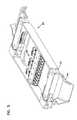
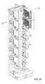
- FIG. 1is a front perspective view of a high-density fiber distribution frame shown with a plurality of slidable fiber optic connection modules having features that are examples of inventive aspects in accordance with the principles of the present disclosure mounted in a stacked arrangement thereon;
- FIG. 1Aillustrates one of the slidable fiber optic connection modules in an extended position
- FIG. 2is a front, top perspective view of a fiber optic connection module shown in isolation, the fiber optic connection module including similar features to those of the connection modules shown in FIG. 1 , the connection module shown in a retracted position;
- FIG. 3is a rear, top perspective view of the fiber optic connection module of FIG. 2 ;
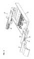
- FIG. 4illustrates the fiber optic connection module of FIG. 2 in a fully extended position
- FIG. 5illustrates the fiber optic connection module of FIG. 3 in a fully extended position
- FIG. 6is a front view of the fiber optic connection module of FIG. 2 ;
- FIG. 7is a front, top perspective view of the connection module of FIG. 2 , with the left center slide member of the module shown in an exploded view;
- FIG. 8is a top view of the connection module of FIG. 2 , with the upper halves of the center slide members removed to illustrate the gear teeth therein;
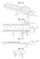
- FIG. 9is a front, top perspective view of the left rack mount member of the slide assembly of the connection module of FIG. 2 , the right rack mount member including similar features to that of the left rack mount member;
- FIG. 10is a rear, top perspective view of the rack mount member of FIG. 9 ;
- FIG. 11is a left side view of the rack mount member of FIG. 9 ;
- FIG. 12is a top view of the rack mount member of FIG. 9 ;
- FIG. 13is a bottom view of the rack mount member of FIG. 9 ;
- FIG. 14is a front view of the rack mount member of FIG. 9 ;
- FIG. 15is a front, top perspective view of the lower half of a center slide member of the connection module of FIG. 2 , the upper half of the center slide member including similar features to that of the lower half;
- FIG. 16is a top view of the lower half of the center slide member of FIG. 15 ;
- FIG. 17is a side view of the lower half of the center slide member of FIG. 15 ;
- FIG. 18is a front view of the lower half of the center slide member of FIG. 15 ;
- FIG. 19is a front, top perspective view of the main frame member of the connection module of FIG. 2 , the main frame member shown without fiber optic adapters mounted thereon;
- FIG. 20is a top view of the main frame member of FIG. 19 ;
- FIG. 21is a left side view of the main frame member of FIG. 19 ;
- FIG. 22is a front view of the main frame member of FIG. 19 ;
- FIG. 24is a cross-sectional view of an example adapter having a media reading interface configured to collect information stored in memory disposed on a fiber optic connector;
- FIG. 25illustrates a telecommunications rack with a plurality of prior art distribution frames or blocks mounted thereon.
- FIGS. 1 and 1AA high-density distribution frame 10 is illustrated in FIGS. 1 and 1A . Similar high-density distribution frames or blocks are described in U.S. Pat. No. 6,591,051, the disclosure of which is incorporated by reference. It should be noted that the high-density fiber distribution frame 10 described herein may be used in a stacked arrangement in a telecommunications rack such as that described in U.S. Pat. No. 6,591,051, incorporated herein by reference in its entirety. Such a telecommunications rack 300 is also shown in FIG. 25 with a plurality of prior art distribution frames or blocks 302 mounted thereon in a stacked arrangement. The example rack defines a vertical cable path 304 with cable management structures 306 for leading cables away from and toward the distribution frames/blocks 302 .
- the fiber distribution frame 10defines a front side 12 , a rear side 14 , a right side 16 , and a left side 18 .
- the fiber distribution frame 10includes a plurality of fiber optic connection modules 20 mounted thereon in a stacked arrangement adjacent both the right side 16 and the left side 18 .
- each of the connection modules 20is separately slidable with respect to the frame 10 between a retracted position and an extended position for the purpose of accessing the fiber optic equipment located in or on the modules 20 .
- the connection modules 20 on the right side 16are slidably extendable in a direction from the left toward the right, and the connection modules 20 on the left side 18 are slidably extendable in a direction from the right toward the left side of the distribution frame 10 .
- connection module 22 shown in FIGS. 2-8is similar to those shown in FIGS. 1 and 1A , except that the connection modules 20 shown in FIGS. 1 and 1A do not include a front wall of the main frame member 24 and also include a cable management spool 26 on each of the right and left sides of the module 20 .
- the version of the module 22 shown in FIGS. 2-8does not include cable management spools on the main frame member 28 but can certainly be modified to do so. It should be noted that the operation and the functionality of both of the versions of the connection modules 20 , 22 ( FIGS. 1 and 1A and FIGS. 2-8 ) are very similar.
- connection modules 20 , 22are shown and described as being mounted on a fiber distribution frame 10 such as that shown in FIGS. 1 and 1A , it should be noted that the distribution frame 10 is only one example of a piece of fiber optic equipment to which modules such as modules 20 and 22 may be mounted.
- connection module 22utilizes a slide assembly 30 including a rack and pinion arrangement allowing the connection module 22 to be slidable between the retracted and extended positions.
- a slide assembly 30including a rack and pinion arrangement allowing the connection module 22 to be slidable between the retracted and extended positions.
- the module 22is configured to manage the slack in the cable routed through the module 22 .
- the slide assembly 30is configured such that when the connection module 22 is moved to the extended position, cables extending from the main frame 28 all the way to the rack mount members 34 maintain the same length and are not stressed or pulled during the travel of the main frame member 28 . Also, the slide assembly 30 is configured such that, when the connection module 22 is moved from the extended position to the retracted position, the slide assembly 30 allows cable management features located on different parts of the module 22 to relatively move with respect to each other, providing management of any slack in the cable.
- the connection module 22includes a main frame member 28 .
- the main frame member 28is configured to provide connection locations 36 for the module 22 .
- the main frame member 28is slidably connected to right and left center members 32 , which are in turn slidably connected to right and left rack mount members 34 of the slide assembly 30 .
- the rack and pinion arrangement of the slide assembly 30is configured such that it provides synchronized slidable movement of the center members 32 and the main frame member 28 when the rear rack mount members 34 are held stationary (for example, mounted to a distribution frame 10 ).
- the slide assembly 30provides synchronized slidable movement for radius limiters located on the center members 32 relative to the main frame member 28 .
- the synchronized movement of the radius limiters of the center members 32 and the main frame member 28ensures that cables routed from the connection locations 36 of the main frame member 28 do not bend too sharply when the main frame member 28 is being extended or retracted. If the cables were to bend too sharply or if the cables were stressed or pulled, loss of signal strength or loss of transmission may occur.
- each center member 32includes a first gear 42 , a second gear 44 , and an idler gear 46 thereinbetween.
- the idler gear 46meshes with the first and second gears 42 , 44 and is configured to transmit the rotational direction of the first gear 42 to the second gear 44 such that the first and second gears 42 , 44 rotate in the same direction.
- the first and second gears 42 , 44mesh with a first rack 48 provided on each of the rack mount members 34 and a second rack 50 provided on each of the right and left sides 38 , 40 of the main frame member 28 .
- the first, second, and idler gears 42 , 44 , 46are configured to provide half speed linear movement for the center members 32 by rotational contact with both the first and second racks 48 , 50 . That is, when the main frame member 28 is slid relative to the rack mount members 34 (or the fiber distribution frame 10 ), the first gear 42 , the second gear 44 , and the idler gear 46 rotate between the first and second racks 48 , 50 to permit the main frame member 28 to travel at full speed and to cause the center members 32 (and thus, the radius limiters of the center members 32 ) to travel at half speed.
- the second rack 50contacts and rotates initially the first gear 42 and then the second gear 44 located on the center members 32 . While the first gear 42 is rotating, the first gear 42 simultaneously contacts the first rack 48 on each of the rack mount members 34 .
- This couplingstarts to move each center member 32 with respect to both the main frame member 28 and each rack mount member 34 , with the center member 32 moving at half the linear speed of the main frame member 28 with respect to the stationary rack mount member 34 .
- the second rack 50reaches the second gear 44 of the center member 32 , the first rack 48 of the rack mount member 34 is only contacting the first gear 42 of the center member 32 .
- both the first and second gears 42 , 44are rotating simultaneously in the same direction via the idler gear 46 , which is rotating in the opposite direction.
- the connection module 22is moved toward the retracted position, the movements of the gears 42 , 44 , 46 of the slide assembly 30 are reversed.
- FIGS. 9-14one of the rack mount members 34 (left rack mount member) of the slide assembly 30 is shown. It should be noted that features discussed with respect to the left rack mount member are fully applicable to the right rack mount member and only one of the rack mount members 34 will be discussed herein for ease of description.
- the rack mount member 34includes mounting holes 52 for receiving fasteners for mounting the connection module 22 to telecommunications equipment such as the high distribution frame 10 shown in FIGS. 1 and 1A .
- the rack mount member 34 of the slide assembly 30is the part of the module 22 that stays stationary with respect to the rest of the module 22 . As discussed above, each center member 32 and the main frame member 28 move with respect to the rack mount member 34 when the connection module 22 is extended or retracted.
- the rack mount member 34includes a divider wall 54 and a radius limiter 56 with a cable management finger 58 .
- the divider wall 54 and the radius limiter 56cooperatively define a cable path 60 for cables coming from the center member 32 .
- the cables that are routed around the radius limiter of the center member 32enter the cable path 60 , pass underneath the cable management finger 58 and are lead down a ramp 62 for connection to further fiber optic equipment.
- the rack mount member 34defines a first longitudinal protrusion 64 that extends from the front to the rear of the rack mount member 34 .
- the longitudinal protrusion 64defines a dovetail shaped profile for slidable insertion into a first dovetail shaped longitudinal groove 66 of the center member 32 as shown in FIGS. 3 and 4 .
- the dovetail shaped profilesprovide for longitudinal slidable coupling between each rack mount member 34 and center member 32 while preventing uncoupling of the two members in a direction perpendicular to the sliding direction.
- each rack mount member 34also defines the first rack 48 .
- the first and second gears 42 , 44 located on the center member 32allow the center member 32 to move simultaneously with the main frame member 28 but at half the linear speed of the main frame member 28 .
- FIG. 7one of the center members 32 of the slide assembly 30 of the connection module 22 is shown in an exploded configuration, wherein the upper and lower halves 68 , 70 of the center member 32 have been separated to expose the gears 42 , 44 , 46 therein.
- FIG. 8also illustrates each of the center members 32 with the upper halves 68 removed, showing the meshing of the first and second gear teeth with the first and second racks 48 , 50 and also showing the idler gear 46 meshing with each of the first and second gears 42 , 44 to maintain the rotational direction between those two gears 42 , 44 .
- the lower half 70 of one of the center members 32is shown in isolation in FIGS. 15-18 . It should be noted that although only the lower half 70 is shown and described herein, all of the features with respect to the lower half 70 are also shared by the upper half 68 of the center member 32 and will not be separately discussed.
- Each of the upper and lower halves 68 , 70 of the center member 32as shown in FIGS. 4, 5, 7 , and 8 , define a radius limiter 72 adjacent the front of the center member 32 .
- the radius limiters 72align to form a single radius limiter 76 located adjacent the front of the center member 32 .
- the radius limiter 76 of the center member 32defines a cable path 80 for cables extending from connection locations 36 of the main frame member 28 . Once cables extend from the main frame member 28 and around the radius limiter 76 , passing through the cable path 60 of the center member 32 , they are led to the cable path 80 defined by the rack mount member 34 .
- each center member 32defines a first notch 82 and a second notch 84 .
- the notches 82 , 84accommodate portions of the rack mount members 34 and also portions of the main frame member 28 in providing stop points during extension and retraction of the connection module 22 .
- the first, second, and idler gears 42 , 44 , 46are placed within each center member 32 via axial pins 86 defined on each gear and openings 88 defined on each of the lower and upper halves 70 , 68 of the center member 32 . Once the gears 42 , 44 , 46 are placed within the openings 88 of the lower half 70 , the upper half 68 is fastened down to the lower half 70 , and the gears 42 , 44 , 46 are free to spin when they are not engaging either of the racks 48 , 50 .
- the center member 32moves in the same direction with the main frame member 28 at half the linear speed of the main frame member 28 .
- cables extending from the main frame member 28(for example around the rear part of the spool 26 shown in FIG. 1 ) to the center member 32 and around the radius limiter 76 of the center member 32 are able to maintain a generally uniform length throughout the travel of the main frame member 28 .
- cables extending from the main frame member 28 all the way to the rack mount members 34are not stressed or pulled during the travel of the main frame member 28 .
- the connection module 22when the connection module 22 is moved from the extended position to the retracted position, the cables maintain their length and any slack in the cables is managed. The maintenance of the cable slack limits any pinching that might occur with fiber optic equipment if there was excessive slack during the retraction of the module 22 .
- the upper and the lower halves 68 , 70 of the center member 32When the upper and the lower halves 68 , 70 of the center member 32 are fastened together, they also cooperatively define the first dovetail shaped longitudinal groove 66 formed on the left side of the center member and a second dovetail shaped longitudinal groove 69 formed on the right side of the center member 32 .
- FIGS. 19-23illustrate one version of the main frame member 28
- a second version 24is illustrated in FIGS. 1 and 1A
- the main frame member 28 shown in FIGS. 19-23is similar to those shown in FIGS. 1 and 1A , except that the main frame member 24 shown in FIGS. 1 and 1A does not include a front wall and also includes a cable management spool 26 on each of the right and left sides of the member 24 , wherein such spools are not shown for the version 28 in FIGS. 19-23 .
- the features shown in FIGS. 1 and 1Acan be included in the version shown in FIGS. 19-23 and vice versa, and that the operation and functionality of both of the versions are very similar.
- the main frame member 28includes a front wall 90 , a rear wall 92 , a right sidewall 94 , and a left sidewall 96 .
- Each of the right and left sidewalls 94 , 96defines a longitudinal protrusion 98 similar to that of the rack mount members 34 for slidable coupling with the center member 32 .
- Each of the longitudinal protrusions 98 of the right wall 94 and the left wall 96defines a dovetail shaped profile for slidable insertion into the second dovetail shaped longitudinal groove 69 of the center member 32 as shown in FIGS. 3 and 8 .
- the dovetail shaped profilesprovide for longitudinal slidable coupling between each center member 32 and the main frame member 28 while preventing uncoupling of the two members in a direction perpendicular to the sliding direction.
- the longitudinal protrusion 98 on each of the right and left sidewalls 94 , 96 of the main frame member 28also defines the second rack 50 .
- the first and second gears 42 , 44 located on the center member 32allow the center member 32 to move at half linear speed simultaneously with the main frame member 28 .
- each of the right sidewall 94 and the left sidewall 96contacts an end 97 of the first notch 82 defined by the radius limiter 76 of each of the center members 32 .
- a front end 55 of the divider wall 54 of each rack mount member 34also contacts an end 99 of the second notch 84 defined by the radius limiter 76 of each of the center members 32 when the connection module 22 is brought to the fully retracted position. In this manner, positive stops are provided for full extension and retraction of the modules 22 .
- the main frame member 28is configured to provide fiber optic connection locations 36 for the connection module 22 .
- the depicted version of the main frame member 28includes a mount 100 for mounting fiber optic adapters 102 which define the fiber optic connection locations 36 in this embodiment of the module 22 .
- the fiber optic connection locations 36are defined by adapters 102 having an LC type footprint.
- twelve LC adapters 102are mounted to the mount 100 via fasteners through fastener openings 104 defined on the mount 100 .
- twelve slidable modulesare mounted on each of right and left sides of the frame 10 .
- Fiber optic adapters 102are only one type of fiber optic equipment that provides connection locations 36 for the module 22 , and the module 22 can be used with other types of fiber optic equipment.
- equipmentsuch as fiber optic splitters, couplers, multiplexers/demultiplexers, or other types of equipment wherein cables may be routed away from the connection locations may be housed on the main frame member 28 .
- connection locationsmay be defined by adapters individually mounted in the mount or may be defined by blocks that include integrally formed adapters.
- the connection locationsmay be in the form of a cassette that includes fiber optic adapters on one side, wherein the opposite side either has a multi-fiber connector or a cable extending outwardly therefrom, as described in further detail in U.S. Publication No. 2013/0089292, incorporated herein by reference in its entirety.
- the slide assembly 30 of the module 22provides access to those fiber optic terminations while managing the cable slack to prevent pinching and preventing pulling or stressing of the cables.
- certain types of adapters 102may be configured to collect physical layer information from one or more fiber optic connectors 135 received thereat.
- certain types of adapter modules 102may include a body 200 configured to hold one or more media reading interfaces 220 that are configured to engage memory contacts on the fiber optic connectors 135 .
- One or more media reading interfaces 220may be positioned in the adapter body 200 .
- the adapter body 200defines slots 210 extending between an exterior of the adapter body 200 and an internal passage in which the ferrules of the connectors 135 are received.
- Certain types of media reading interfaces 220include one or more contact members 221 that are positioned in the slots 210 . As shown in FIG. 24 , a portion of each contact member 221 extends into a respective one of the passages to engage memory contacts on a fiber optic connector 130 . Another portion of each contact member 221 also extends out of the slot 210 to contact a circuit board 230 . Portions of the main frame member 28 may define conductive paths that are configured to connect the media reading interfaces 220 of the adapter 102 with a master circuit board.
- the master circuit boardmay include or connect (e.g., over a network) to a processing unit that is configured to manage physical layer information obtained by the media reading interfaces.
- Example adapters having media reading interfaces and example fiber optic connectors having suitable memory storage and memory contactsare shown in U.S. Pat. No. 8,690,593, the disclosure of which is hereby incorporated by reference.
Landscapes
- Physics & Mathematics (AREA)
- General Physics & Mathematics (AREA)
- Optics & Photonics (AREA)
- Light Guides In General And Applications Therefor (AREA)
Abstract
Description
Claims (13)
Priority Applications (5)
| Application Number | Priority Date | Filing Date | Title |
|---|---|---|---|
| US15/397,341US9977213B2 (en) | 2011-10-07 | 2017-01-03 | Slidable fiber optic connection module with cable slack management |
| US15/983,784US10437000B2 (en) | 2011-10-07 | 2018-05-18 | Slidable fiber optic connection module with cable slack management |
| US16/588,061US10948675B2 (en) | 2011-10-07 | 2019-09-30 | Slidable fiber optic connection module with cable slack management |
| US17/187,314US11340417B2 (en) | 2011-10-07 | 2021-02-26 | Slidable fiber optic connection module with cable slack management |
| US17/730,586US11698501B2 (en) | 2011-10-07 | 2022-04-27 | Slidable fiber optic connection module with cable slack management |
Applications Claiming Priority (4)
| Application Number | Priority Date | Filing Date | Title |
|---|---|---|---|
| US201161544965P | 2011-10-07 | 2011-10-07 | |
| US13/645,674US9170391B2 (en) | 2011-10-07 | 2012-10-05 | Slidable fiber optic connection module with cable slack management |
| US14/922,996US9541725B2 (en) | 2011-10-07 | 2015-10-26 | Slidable fiber optic connection module with cable slack management |
| US15/397,341US9977213B2 (en) | 2011-10-07 | 2017-01-03 | Slidable fiber optic connection module with cable slack management |
Related Parent Applications (1)
| Application Number | Title | Priority Date | Filing Date |
|---|---|---|---|
| US14/922,996ContinuationUS9541725B2 (en) | 2011-10-07 | 2015-10-26 | Slidable fiber optic connection module with cable slack management |
Related Child Applications (1)
| Application Number | Title | Priority Date | Filing Date |
|---|---|---|---|
| US15/983,784ContinuationUS10437000B2 (en) | 2011-10-07 | 2018-05-18 | Slidable fiber optic connection module with cable slack management |
Publications (2)
| Publication Number | Publication Date |
|---|---|
| US20170235078A1 US20170235078A1 (en) | 2017-08-17 |
| US9977213B2true US9977213B2 (en) | 2018-05-22 |
Family
ID=48042130
Family Applications (7)
| Application Number | Title | Priority Date | Filing Date |
|---|---|---|---|
| US13/645,674Active2034-01-21US9170391B2 (en) | 2011-10-07 | 2012-10-05 | Slidable fiber optic connection module with cable slack management |
| US14/922,996ActiveUS9541725B2 (en) | 2011-10-07 | 2015-10-26 | Slidable fiber optic connection module with cable slack management |
| US15/397,341ActiveUS9977213B2 (en) | 2011-10-07 | 2017-01-03 | Slidable fiber optic connection module with cable slack management |
| US15/983,784ActiveUS10437000B2 (en) | 2011-10-07 | 2018-05-18 | Slidable fiber optic connection module with cable slack management |
| US16/588,061ActiveUS10948675B2 (en) | 2011-10-07 | 2019-09-30 | Slidable fiber optic connection module with cable slack management |
| US17/187,314ActiveUS11340417B2 (en) | 2011-10-07 | 2021-02-26 | Slidable fiber optic connection module with cable slack management |
| US17/730,586ActiveUS11698501B2 (en) | 2011-10-07 | 2022-04-27 | Slidable fiber optic connection module with cable slack management |
Family Applications Before (2)
| Application Number | Title | Priority Date | Filing Date |
|---|---|---|---|
| US13/645,674Active2034-01-21US9170391B2 (en) | 2011-10-07 | 2012-10-05 | Slidable fiber optic connection module with cable slack management |
| US14/922,996ActiveUS9541725B2 (en) | 2011-10-07 | 2015-10-26 | Slidable fiber optic connection module with cable slack management |
Family Applications After (4)
| Application Number | Title | Priority Date | Filing Date |
|---|---|---|---|
| US15/983,784ActiveUS10437000B2 (en) | 2011-10-07 | 2018-05-18 | Slidable fiber optic connection module with cable slack management |
| US16/588,061ActiveUS10948675B2 (en) | 2011-10-07 | 2019-09-30 | Slidable fiber optic connection module with cable slack management |
| US17/187,314ActiveUS11340417B2 (en) | 2011-10-07 | 2021-02-26 | Slidable fiber optic connection module with cable slack management |
| US17/730,586ActiveUS11698501B2 (en) | 2011-10-07 | 2022-04-27 | Slidable fiber optic connection module with cable slack management |
Country Status (1)
| Country | Link |
|---|---|
| US (7) | US9170391B2 (en) |
Cited By (2)
| Publication number | Priority date | Publication date | Assignee | Title |
|---|---|---|---|---|
| US20190137714A1 (en)* | 2011-10-07 | 2019-05-09 | Commscope Technologies Llc | Slidable fiber optic connection module with cable slack management |
| US11686911B2 (en) | 2020-09-17 | 2023-06-27 | Panduit Corp. | Optical distribution and splice frame including enclosures |
Families Citing this family (38)
| Publication number | Priority date | Publication date | Assignee | Title |
|---|---|---|---|---|
| US9002166B2 (en)* | 2011-10-07 | 2015-04-07 | Adc Telecommunications, Inc. | Slidable fiber optic connection module with cable slack management |
| CN103975264B (en) | 2011-10-07 | 2015-09-16 | Adc电信公司 | Slidable fiber optic connection module with cable slack management |
| US9075203B2 (en) | 2012-01-17 | 2015-07-07 | Adc Telecommunications, Inc. | Fiber optic adapter block |
| US9195021B2 (en) | 2012-09-21 | 2015-11-24 | Adc Telecommunications, Inc. | Slidable fiber optic connection module with cable slack management |
| US10082636B2 (en) | 2012-09-21 | 2018-09-25 | Commscope Technologies Llc | Slidable fiber optic connection module with cable slack management |
| CN105074525A (en) | 2013-01-29 | 2015-11-18 | 泰科电子瑞侃有限公司 | Fiber Distribution System |
| US9128262B2 (en) | 2013-02-05 | 2015-09-08 | Adc Telecommunications, Inc. | Slidable telecommunications tray with cable slack management |
| WO2014133943A1 (en) | 2013-02-27 | 2014-09-04 | Adc Telecommunications, Inc. | Slidable fiber optic connection module with cable slack management |
| AP2015008820A0 (en) | 2013-04-24 | 2015-10-31 | Adc Czech Republic Sro | Optical fiber distribution system |
| EP2989496B1 (en) | 2013-04-24 | 2019-06-12 | CommScope Connectivity Belgium BVBA | Universal mounting mechanism for mounting a telecommunications chassis to a telecommunications fixture |
| JP2015215386A (en)* | 2014-05-08 | 2015-12-03 | 株式会社日立製作所 | Optical wiring unit |
| WO2016094331A1 (en) | 2014-12-10 | 2016-06-16 | Commscope Technologies Llc | Fiber optic cable slack management module |
| WO2016154092A1 (en)* | 2015-03-23 | 2016-09-29 | Commscope Technologies Llc | Fiber optic module and chassis with cable slack management |
| AU2016239875C1 (en) | 2015-04-03 | 2021-06-24 | CommScope Connectivity Belgium BVBA | Telecommunications distribution elements |
| US9851523B2 (en) | 2015-09-22 | 2017-12-26 | Go!Foton Holdings, Inc. | Apparatus for cable routing |
| WO2017184501A1 (en) | 2016-04-19 | 2017-10-26 | Commscope, Inc. Of North Carolina | Door assembly for a telecommunications chassis with a combination hinge structure |
| ES2851948T3 (en) | 2016-04-19 | 2021-09-09 | Commscope Inc North Carolina | Telecom rack with slide out trays |
| US10310206B2 (en)* | 2017-05-22 | 2019-06-04 | Go!Foton Holdings, Inc. | Apparatus for cable routing |
| WO2018226959A1 (en) | 2017-06-07 | 2018-12-13 | Commscope Technologies Llc | Fiber optic adapter and cassette |
| US10670822B2 (en) | 2017-06-28 | 2020-06-02 | Afl Telecommunications Llc | High density patch panel with modular cassettes |
| US11385429B2 (en) | 2017-10-18 | 2022-07-12 | Commscope Technologies Llc | Fiber optic connection cassette |
| CN109752807B (en)* | 2017-11-06 | 2021-10-15 | 北京华为数字技术有限公司 | Pull-out modules, sub-frames and optical sub-boxes |
| US11852882B2 (en) | 2018-02-28 | 2023-12-26 | Commscope Technologies Llc | Packaging assembly for telecommunications equipment |
| WO2019204317A1 (en) | 2018-04-16 | 2019-10-24 | Commscope Technologies Llc | Adapter structure |
| US11635578B2 (en) | 2018-04-17 | 2023-04-25 | CommScope Connectivity Belgium BVBA | Telecommunications distribution elements |
| EP3845044B1 (en) | 2018-08-31 | 2023-02-15 | CommScope Connectivity Belgium BVBA | Frame assemblies for optical fiber distribution elements |
| WO2020043914A1 (en) | 2018-08-31 | 2020-03-05 | CommScope Connectivity Belgium BVBA | Frame assemblies for optical fiber distribution elements |
| EP3844547A1 (en) | 2018-08-31 | 2021-07-07 | CommScope Connectivity Belgium BVBA | Frame assemblies for optical fiber distribution elements |
| EP3844546A1 (en) | 2018-08-31 | 2021-07-07 | CommScope Connectivity Belgium BVBA | Frame assemblies for optical fiber distribution elements |
| PL3844973T3 (en) | 2018-08-31 | 2025-03-03 | CommScope Connectivity Belgium BVBA | Frame assemblies for optical fiber distribution elements |
| WO2020084012A1 (en) | 2018-10-23 | 2020-04-30 | CommScope Connectivity Belgium BVBA | Frame assemblies for optical fiber distribution elements |
| CN109270643B (en)* | 2018-11-09 | 2024-02-13 | 欧博通信(深圳)有限公司 | Optical fiber distribution frame |
| CN111385999B (en)* | 2018-12-29 | 2021-06-29 | 北京华为数字技术有限公司 | A subrack and communication equipment |
| EP3914947A1 (en) | 2019-01-25 | 2021-12-01 | CommScope Connectivity Belgium BVBA | Frame assemblies for optical fiber distribution elements |
| EP4236343B1 (en) | 2019-04-17 | 2025-03-12 | Afl Ig Llc | Patch panel with lifting cassette removal |
| WO2021148544A1 (en) | 2020-01-22 | 2021-07-29 | CommScope Connectivity Belgium BVBA | Cable termination units for optical fiber distribution elements |
| US12099246B2 (en) | 2020-01-24 | 2024-09-24 | CommScope Connectivity Belgium BVBA | Telecommunications distribution elements |
| CN111474646B (en)* | 2020-04-17 | 2020-11-17 | 东阳市聚铕新材料有限公司 | Broadband distribution case device based on fixed convenient dismantlement of button |
Citations (190)
| Publication number | Priority date | Publication date | Assignee | Title |
|---|---|---|---|---|
| US2805106A (en) | 1954-12-27 | 1957-09-03 | Metal Trim Ltd | Double extension slides |
| US2864656A (en) | 1954-06-25 | 1958-12-16 | Yorinks Alexander | Slide mechanism |
| US3901564A (en) | 1973-10-29 | 1975-08-26 | Henry P Armstrong | Drawer extensible slide chassis |
| US4070076A (en) | 1977-05-05 | 1978-01-24 | The Raymond Lee Organization, Inc. | Drawer sliding device |
| DE2735106A1 (en) | 1977-08-04 | 1979-02-15 | Licentia Gmbh | Telecommunications cable fitting arrangement - uses fibre=optics conductors together with copper core conductors in one cable |
| US4172625A (en) | 1977-12-15 | 1979-10-30 | Comerco, Inc. | Drawer extenders |
| DE2918309A1 (en) | 1979-05-07 | 1980-11-13 | Schulz Kunststoff Heino | Guide rail assembly for drawer - consists of outer, central and drawer rail with pinion and toothed rack |
| US4320934A (en) | 1978-06-13 | 1982-03-23 | Julius Blum Gesellschaft M.B.H. | Pull-out guide for drawers |
| US4359262A (en) | 1980-06-30 | 1982-11-16 | Northern Telecom Limited | Tray for organizing optical fiber splices and enclosures embodying such trays |
| US4373776A (en) | 1980-06-30 | 1983-02-15 | Northern Telecom Limited | Protection case for optical fiber splices |
| FR2531576A1 (en) | 1982-08-04 | 1984-02-10 | Cit Alcatel | CONNECTION AND OPTO-ELECTRONIC INTERFACE |
| JPS5974523A (en) | 1982-10-21 | 1984-04-27 | Furukawa Electric Co Ltd:The | fiber optic junction box |
| DE3308682A1 (en) | 1983-03-11 | 1984-09-20 | Krone Gmbh, 1000 Berlin | Matrix main distribution frame |
| US4494806A (en) | 1983-05-13 | 1985-01-22 | Leslie Metal Arts Company | Spring loaded drawer assembly with mechanical damping |
| US4502754A (en) | 1982-01-19 | 1985-03-05 | Nippon Electric Co., Ltd. | Optical fiber interconnection mechanism |
| EP0146478A2 (en) | 1983-12-20 | 1985-06-26 | Lignes Telegraphiques Et Telephoniques L.T.T. | Joining apparatus for cables, especially optical fibres |
| EP0149250A2 (en) | 1983-12-30 | 1985-07-24 | Wilhelm Sedlbauer GmbH Fabrik für Feinmechanik und Elektronik | Distribution mounting for the end parts of glassfibre cables |
| JPS60169811A (en) | 1984-02-14 | 1985-09-03 | Furukawa Electric Co Ltd:The | Containing device for connection excessive length of optical fiber |
| AU4099585A (en) | 1984-04-11 | 1985-10-17 | N.V. Raychem S.A. | Splice case for optical fibre cable |
| JPS6155607A (en) | 1984-08-28 | 1986-03-20 | Fujitsu Ltd | optical distribution board |
| US4585303A (en) | 1982-08-04 | 1986-04-29 | Compagnie Industrielle Des Telecommunication Cit-Alcatel | Optical cable header |
| JPS6190104A (en) | 1984-10-09 | 1986-05-08 | Nec Corp | Optical adapter installation structure |
| US4595255A (en) | 1983-08-24 | 1986-06-17 | Fiberlan, Inc. | Optical fiber wiring center |
| AU5531486A (en) | 1985-03-29 | 1986-10-02 | Siemens Aktiengesellschaft | Coupling rack for glassfibre cables |
| US4630886A (en) | 1984-04-16 | 1986-12-23 | At&T Bell Laboratories | Lightguide distributing unit |
| FR2587127A1 (en) | 1985-09-06 | 1987-03-13 | Valleix Paul | STRUCTURE FOR OPTICAL CONNECTIONS |
| US4697874A (en) | 1984-12-14 | 1987-10-06 | Nozick Jacques E | Distribution frame for optical cables |
| US4699455A (en) | 1985-02-19 | 1987-10-13 | Allen-Bradley Company | Fiber optic connector |
| US4708430A (en) | 1984-10-25 | 1987-11-24 | Northern Telecom Limited | Cabinet for optical cable terminating equipment |
| US4717231A (en) | 1983-01-05 | 1988-01-05 | Vincent Dewez | Interconnecting and distributing box for optical fibers |
| US4737039A (en) | 1986-12-08 | 1988-04-12 | Knape & Vogt Manufacturing Company | Drawer rail carrier roller mount |
| US4765710A (en) | 1985-07-30 | 1988-08-23 | Siemens Aktiengesellschaft | Distributing frame for optical waveguides and the like |
| US4792203A (en) | 1985-09-17 | 1988-12-20 | Adc Telecommunications, Inc. | Optical fiber distribution apparatus |
| US4820007A (en) | 1988-02-12 | 1989-04-11 | American Telephone And Telegraph Company At&T Bell Laboratories | Cable closure and methods of assembling |
| US4840449A (en) | 1988-01-27 | 1989-06-20 | American Telephone And Telegraph Company, At&T Bell Laboratories | Optical fiber splice organizer |
| US4898448A (en) | 1988-05-02 | 1990-02-06 | Gte Products Corporation | Fiber distribution panel |
| EP0356942A2 (en) | 1988-08-29 | 1990-03-07 | Gte Control Devices Of Puerto Rico Incorporated | 1550NM fiber distribution panel |
| DE3836273A1 (en) | 1988-10-25 | 1990-04-26 | Standard Praezision Gmbh | Synchronised three-membered telescopic rail for draw-out members |
| US4971421A (en) | 1989-09-29 | 1990-11-20 | Reliance Comm/Tec Corporation | Fiber optic splice and patch enclosure |
| EP0406151A2 (en) | 1989-06-29 | 1991-01-02 | Adc Telecommunications, Inc. | Optical fiber storage container |
| US4986762A (en) | 1989-08-15 | 1991-01-22 | Minnesota Mining And Manufacturing Company | Termination module for use in an array of modules |
| US4995688A (en) | 1989-07-31 | 1991-02-26 | Adc Telecommunications, Inc. | Optical fiber distribution frame |
| US5024498A (en) | 1988-11-12 | 1991-06-18 | U.S. Philips Corp. | Switch box for producing freely selectable optical plug connections |
| WO1991010927A1 (en) | 1990-01-22 | 1991-07-25 | Porta Systems Corp. | Optical fiber cable distribution frame and support |
| US5066149A (en) | 1990-09-11 | 1991-11-19 | Adc Telecommunications, Inc. | Splice tray with slack take-up |
| US5067678A (en) | 1989-07-31 | 1991-11-26 | Adc Telecommunications, Inc. | Optic cable management system |
| US5071211A (en) | 1988-12-20 | 1991-12-10 | Northern Telecom Limited | Connector holders and distribution frame and connector holder assemblies for optical cable |
| EP0464570A1 (en) | 1990-06-29 | 1992-01-08 | Alcatel Cit | Modular device for storing reserves of transmission means in a transmission line, notably fibre optic |
| EP0479226A1 (en) | 1990-10-04 | 1992-04-08 | MARS-ACTEL Société Anonyme dite: | Cassette for optical junction |
| US5127082A (en) | 1991-03-22 | 1992-06-30 | The Siemon Company | Fiber optic patch panel |
| US5129030A (en) | 1991-05-30 | 1992-07-07 | At&T Bell Laboratories | Movable lightguide connector panel |
| US5138688A (en) | 1990-11-09 | 1992-08-11 | Northern Telecom Limited | Optical connector holder assembly |
| US5142607A (en) | 1990-03-20 | 1992-08-25 | Rittal-Werk Rudolf Loh Gmbh & Co. Kg | Splice box for optical wave guide |
| US5142606A (en) | 1990-01-22 | 1992-08-25 | Porta Systems Corp. | Optical fiber cable distribution frame and support |
| US5167001A (en) | 1991-09-03 | 1992-11-24 | Northern Telecom Limited | Optical fiber storage and connector tray and shelf and tray assembly |
| FR2678076A1 (en) | 1991-06-20 | 1992-12-24 | Cit Alcatel | MODULE FOR STORING A TRANSMISSION SUPPORT RESERVE ON A LINK, PARTICULARLY WITH OPTICAL FIBER AND STORAGE DEVICE COMPRISING A SET OF SUCH MODULES. |
| US5174675A (en) | 1990-05-07 | 1992-12-29 | Inventio Ag | Guide bar for an elevator door |
| EP0538164A1 (en) | 1991-10-15 | 1993-04-21 | France Telecom | Distribution head for high capacity optical cables |
| US5240209A (en) | 1992-11-17 | 1993-08-31 | Telect, Inc. | Telecommunication multiple cable carrier |
| US5247603A (en) | 1992-01-24 | 1993-09-21 | Minnesota Mining And Manufacturing Company | Fiber optic connection system with exchangeable cross-connect and interconnect cards |
| US5275064A (en) | 1992-06-12 | 1994-01-04 | General Devices Co., Inc. | Extensible platform with cable drive system |
| US5285515A (en) | 1992-02-21 | 1994-02-08 | Mars Actel | Adaptable cassette for coiling and splicing optical fibers |
| US5289558A (en) | 1991-10-05 | 1994-02-22 | Krone Aktiengesellshaft | Switching assembly for glass fiber cables of the telecommunication and data technology |
| US5316243A (en) | 1989-07-31 | 1994-05-31 | Adc Telecommunications, Inc. | Optic cable management |
| US5323480A (en) | 1992-11-25 | 1994-06-21 | Raychem Corporation | Fiber optic splice closure |
| US5335349A (en) | 1992-12-14 | 1994-08-02 | Telect, Inc. | Telecommunication overhead cable distribution assembly |
| US5339379A (en) | 1993-06-18 | 1994-08-16 | Telect, Inc. | Telecommunication fiber optic cable distribution apparatus |
| US5353367A (en) | 1993-11-29 | 1994-10-04 | Northern Telecom Limited | Distribution frame and optical connector holder combination |
| US5363467A (en) | 1993-05-28 | 1994-11-08 | Minnesota Mining And Manufacturing Company | Compact fiber optic housing |
| US5363466A (en) | 1992-02-21 | 1994-11-08 | Mars Actel | Assembly of hinged flat modules |
| WO1995007480A1 (en) | 1993-09-08 | 1995-03-16 | N.V. Raychem S.A. | Organization of optical fibres |
| US5402515A (en) | 1994-03-01 | 1995-03-28 | Minnesota Mining And Manufacturing Company | Fiber distribution frame system, cabinets, trays and fiber optic connector couplings |
| US5412751A (en) | 1993-08-31 | 1995-05-02 | The Siemon Company | Retrofittable multimedia patch management system |
| DE4413136C1 (en) | 1994-04-19 | 1995-05-04 | Loh Kg Rittal Werk | Optical-fibre splice box |
| US5438641A (en) | 1993-03-26 | 1995-08-01 | Corning Incorporated | Optical fiber component cassette with pigtail tube assembly |
| US5490229A (en) | 1993-12-08 | 1996-02-06 | At&T Ipm Corp. | Slidably mounted optical fiber distribution tray |
| US5497444A (en) | 1994-01-21 | 1996-03-05 | Adc Telecommunications, Inc. | High-density fiber distribution frame |
| DE29504191U1 (en) | 1995-03-01 | 1996-03-28 | Krone Ag, 14167 Berlin | Insert for receiving devices of the LWL technology |
| WO1996010203A1 (en) | 1994-09-28 | 1996-04-04 | Telephone Cables Limited | A splice tray |
| US5509096A (en) | 1994-10-28 | 1996-04-16 | Syntec Inc. | Receptacle and plug fiber optic connector assembly |
| US5511144A (en) | 1994-06-13 | 1996-04-23 | Siecor Corporation | Optical distribution frame |
| US5530783A (en) | 1994-08-31 | 1996-06-25 | Berg Technology, Inc. | Backplane optical fiber connector for engaging boards of different thicknesses and method of use |
| US5570450A (en) | 1991-12-12 | 1996-10-29 | Telefonica De Espana, S.A. | Junction and modular optical sharing terminal assembly |
| US5613030A (en) | 1995-05-15 | 1997-03-18 | The Whitaker Corporation | High density fiber optic interconnection enclosure |
| US5640481A (en) | 1994-08-15 | 1997-06-17 | Pirelli General Plc | Guiding optical fibres |
| US5655044A (en) | 1994-12-01 | 1997-08-05 | Siemens Aktiengesellschaft | Cassette module having swingable cassettes and a backplane with guide ridges for guiding light waveguides and optical fibers |
| US5724469A (en) | 1996-01-26 | 1998-03-03 | Ortronics, Inc. | Adjustable fiber storage plate |
| US5802237A (en) | 1997-04-18 | 1998-09-01 | Minnesota Mining And Manufacturing Company | Optical fiber organizer |
| US5811055A (en) | 1996-02-06 | 1998-09-22 | Geiger; Michael B. | Torch mounted gas scavaging system for manual and robotic welding and cutting torches |
| US5836148A (en) | 1996-02-06 | 1998-11-17 | Kunimorikagaku Ltd. | Cable chain |
| WO1999000619A1 (en) | 1997-06-26 | 1999-01-07 | Crane Nuclear, Inc. | Method and apparatus for on-line detection of leaky emergency shut down or other valves |
| US5882100A (en) | 1996-10-07 | 1999-03-16 | Julius Blum Gesellschaft M.B.H. | Pull out guide assembly for drawers and the like |
| US5887106A (en) | 1996-04-12 | 1999-03-23 | Telephone Cables Limited | Management of optical fiber |
| US5917984A (en) | 1996-03-14 | 1999-06-29 | Krone Aktiengesellschaft | Management-capable splice cassette |
| US5923753A (en) | 1997-11-17 | 1999-07-13 | Adc Telecommunications, Inc. | Optic cable exit trough with bypass |
| US5946440A (en) | 1997-11-17 | 1999-08-31 | Adc Telecommunications, Inc. | Optical fiber cable management device |
| US5966492A (en) | 1997-12-19 | 1999-10-12 | Antec Corporation | Apparatus for storing and splicing optical fibers |
| EP0563995B1 (en) | 1992-04-03 | 1999-10-13 | The Whitaker Corporation | Optical fiber connector |
| US5971626A (en) | 1997-08-29 | 1999-10-26 | Siecor Corporation | Fiber optic connector and connector sleeve assembly |
| US5978540A (en) | 1998-04-23 | 1999-11-02 | Antec Corporation | Apparatus for interconnecting optical fibers |
| US5975769A (en) | 1997-07-08 | 1999-11-02 | Telect, Inc. | Universal fiber optic module system |
| US6009224A (en) | 1997-11-06 | 1999-12-28 | Allen; Barry Wayne | Fiber optic organizer with lockable trays and method of accessing a tray |
| US6022150A (en) | 1997-04-30 | 2000-02-08 | The Whitaker Corporation | Fiber optic connector |
| US6027252A (en) | 1997-12-19 | 2000-02-22 | The Whitaker Corporation | Simplified fiber optic receptacle |
| US6044194A (en) | 1997-03-17 | 2000-03-28 | Tii-Ditel, Inc. | Fiber optic cable bend radius control |
| US6076908A (en) | 1998-09-17 | 2000-06-20 | Platt And Labonia Co. | Drawer for storage cabinet |
| US6215938B1 (en) | 1998-09-21 | 2001-04-10 | Adc Telecommunications, Inc. | Fiber optic cabinet and tray |
| US6226436B1 (en) | 1999-11-18 | 2001-05-01 | Lucent Technologies, Inc. | Fiber optical pedestal |
| US20010001270A1 (en) | 1998-07-21 | 2001-05-17 | Adc Telecommunications, Inc. | Fiber optic module |
| US6236795B1 (en) | 1999-06-07 | 2001-05-22 | E. Walter Rodgers | High-density fiber optic cable distribution frame |
| US6269214B1 (en) | 1998-08-04 | 2001-07-31 | Pouyet, S.A. | Device for interconnecting optical fiber cables |
| US6301424B1 (en) | 2000-04-13 | 2001-10-09 | Lucent Technologies Inc. | Distribution frame cable routing apparatus |
| US6360050B1 (en) | 2000-09-08 | 2002-03-19 | Telect, Inc. | High density fiber distribution tray system |
| US6438310B1 (en) | 2000-01-24 | 2002-08-20 | Adc Telecommunications, Inc. | Cable management panel with sliding drawer |
| US6439523B1 (en) | 2000-06-02 | 2002-08-27 | Panduit Corp. | Universal mounting system for a fiber optic management center |
| US20020181922A1 (en) | 2001-06-01 | 2002-12-05 | Xin Xin | High density fiber optic splitter/connector tray system |
| US6496638B1 (en) | 1998-10-23 | 2002-12-17 | Lucent Technologies Inc. | Optical fiber cassette |
| US6504988B1 (en) | 2000-01-24 | 2003-01-07 | Adc Telecommunications, Inc. | Cable management panel with sliding drawer |
| US20030007767A1 (en) | 2001-07-06 | 2003-01-09 | Douglas Joel B. | Cable management panel with sliding drawer and methods |
| US6591051B2 (en) | 2001-11-16 | 2003-07-08 | Adc Telecommunications, Inc. | Fiber termination block with angled slide |
| US20030128951A1 (en) | 2001-11-13 | 2003-07-10 | Didier Lecomte | Optical fiber connection and distribution module intended for use in an optical distribution frame |
| US6594434B1 (en) | 2001-10-26 | 2003-07-15 | Ciena Corporation | Fiber optic cables management and measurement apparatus |
| US6600866B2 (en) | 2001-03-13 | 2003-07-29 | 3M Innovative Properties Company | Filament organizer |
| US20030174996A1 (en) | 2002-03-15 | 2003-09-18 | Fiber Optic Network Solutions, Inc. | Optical fiber enclosure system using integrated optical connector and coupler assembly |
| US20030190035A1 (en) | 2002-04-05 | 2003-10-09 | Knudsen Clinton M. | Termination frame with modules and method |
| KR200337929Y1 (en) | 2003-10-23 | 2004-01-13 | 허필규 | A Housing for purchase of optical fiber adapter |
| US6677520B1 (en) | 2002-07-22 | 2004-01-13 | Adc Telecommunications, Inc. | Fanning tray |
| US20040011750A1 (en) | 2002-07-22 | 2004-01-22 | Matthew Kim | Fiber management drawer and patch panel |
| US6748155B2 (en) | 2002-07-22 | 2004-06-08 | Adc Telecommunications, Inc. | Fiber management drawer and sliding cable slack limiter |
| US6768860B2 (en) | 2002-12-05 | 2004-07-27 | Jds Uniphase Inc. | High density fiber optic module |
| US20040175090A1 (en) | 2001-04-02 | 2004-09-09 | Kristof Vastmans | Optical fibre organiser |
| US6804447B2 (en) | 2002-11-05 | 2004-10-12 | Adc Telecommunications, Inc. | Fiber panel with integrated couplers |
| US6810193B1 (en) | 1999-11-22 | 2004-10-26 | Ccs Technology, Inc. | Cassette for receiving optical waveguides with overlengths and fiber splices |
| US6809258B1 (en) | 2003-02-24 | 2004-10-26 | Cisco Technology, Inc. | Apparatus for cable routing management |
| US6845208B2 (en) | 2001-11-13 | 2005-01-18 | Nexans | Optical high-density distribution frame and method for making jumper connections in such a distribution frame |
| US20050025444A1 (en) | 2003-07-31 | 2005-02-03 | Barnes Kathleen M. | Slide arrangement for cable drawer |
| US6865331B2 (en) | 2003-01-15 | 2005-03-08 | Adc Telecommunications, Inc. | Rotating radius limiter for cable management panel and methods |
| US20050058421A1 (en) | 2003-03-05 | 2005-03-17 | Dagley Mark R. | High density fiber optic distribution frame |
| US20050078929A1 (en) | 2002-01-03 | 2005-04-14 | Waldemar Iwanek | Splicing cassette management system |
| US20050100301A1 (en) | 1999-03-01 | 2005-05-12 | Adc Telecommunications, Inc. | Optical fiber distribution frame with outside plant enclosure |
| US20050123261A1 (en) | 2002-04-12 | 2005-06-09 | Kathleen Bellekens | Optical circuit enclosure |
| US6925241B2 (en) | 2002-10-11 | 2005-08-02 | 3M Innovative Properties Company | Drawer for the management of optical fibers |
| US6934457B2 (en) | 2002-02-25 | 2005-08-23 | Nexans | Cassette for coiling optical fibers |
| US6945620B2 (en) | 2002-05-17 | 2005-09-20 | Harn Marketing Sdn Bhd | Guide rails for pull-out drawer/equipment |
| US7068907B2 (en) | 2001-02-12 | 2006-06-27 | Fiber Optic Network Solutions, Corp. | Optical fiber enclosure system |
| US20060275008A1 (en) | 2005-06-03 | 2006-12-07 | Telect, Inc. | Fiber management system |
| US20070003204A1 (en) | 2005-06-30 | 2007-01-04 | Elli Makrides-Saravanos | Methods and apparatus for splitter modules and splitter module housings |
| US20070031099A1 (en) | 2005-08-02 | 2007-02-08 | Herzog Daniel J | Cable management panel with rear entry |
| US7302153B2 (en) | 2005-10-26 | 2007-11-27 | Telect Inc. | Fiber management access system |
| KR20080033420A (en) | 2005-07-27 | 2008-04-16 | 에이디씨 텔레커뮤니케이션스 인코포레이티드 | Fiber optical adapter module |
| US7367823B2 (en) | 2003-12-23 | 2008-05-06 | Adc Telecommunications, Inc. | Fiber optic module |
| US20080175550A1 (en) | 2007-01-19 | 2008-07-24 | Hutch Coburn | Fiber optic adapter cassette and panel |
| US7406240B2 (en) | 2005-07-21 | 2008-07-29 | Ortronics, Inc. | Patch panel for fiber optic network |
| US7409137B2 (en) | 2006-10-04 | 2008-08-05 | Adc Telecommunications, Inc. | Slide arrangement for cable drawer |
| US7460757B2 (en) | 2002-11-22 | 2008-12-02 | Adc Gmbh | Distributor system and method for fibre optic cables |
| US7496268B2 (en) | 2006-12-13 | 2009-02-24 | Corning Cable Systems Llc | High density fiber optic hardware |
| US20090067800A1 (en) | 2007-09-07 | 2009-03-12 | Mariano Perez Vazquez | Fiber optic adapter module and tray |
| US20090097813A1 (en) | 2007-10-01 | 2009-04-16 | John Paul Hill | Modular optical fiber cassettes and fiber management methods |
| US20090274431A1 (en) | 2008-03-28 | 2009-11-05 | Dennis Krampotich | Bulkhead with angled openings and method |
| US20090274430A1 (en) | 2008-05-05 | 2009-11-05 | Dennis Krampotich | Drawer arrangement with rack and pinion |
| US7689089B2 (en) | 2006-10-11 | 2010-03-30 | Panduit Corp. | Release latch for pre-terminated cassette |
| US7706656B2 (en) | 2005-05-25 | 2010-04-27 | Adc Telecommunications, Inc. | Fiber optic adapter module |
| US7715681B2 (en) | 2008-03-28 | 2010-05-11 | Adc Telecommunications, Inc. | Rear latch arrangement for sliding drawer |
| US20100142910A1 (en) | 2007-10-01 | 2010-06-10 | Clearfield, Inc. | Modular optical fiber cassette |
| US20100158465A1 (en) | 2008-12-09 | 2010-06-24 | Mark Smrha | Fiber optic adapter plate and cassette |
| US7747125B1 (en) | 2007-11-07 | 2010-06-29 | Alliance Fiber Optic Products, Inc. | Structured fiber optic cassette with multi-furcated cable access |
| US7764859B2 (en) | 2008-03-28 | 2010-07-27 | Adc Telecommunications, Inc. | Universal cable management panel |
| US7856166B2 (en) | 2008-09-02 | 2010-12-21 | Corning Cable Systems Llc | High-density patch-panel assemblies for optical fiber telecommunications |
| US20100322578A1 (en) | 2009-06-19 | 2010-12-23 | Cooke Terry L | Mounting of Fiber Optic Cable Assemblies Within Fiber Optic Shelf Assemblies |
| US7889961B2 (en) | 2008-03-27 | 2011-02-15 | Corning Cable Systems Llc | Compact, high-density adapter module, housing assembly and frame assembly for optical fiber telecommunications |
| US20110188809A1 (en) | 2010-02-02 | 2011-08-04 | Adc Telecommunications, Inc. | Fiber optic cable bundle with staggered connectors |
| US20110211799A1 (en) | 2008-10-27 | 2011-09-01 | Mark Edward Conner | Variably configurable and modular local convergence point |
| US20110217016A1 (en) | 2008-02-01 | 2011-09-08 | Mullsteff David M | Fiber optic communication system |
| US20110268408A1 (en) | 2010-04-30 | 2011-11-03 | Giraud William J | Door fiber management for fiber optic housings, and related components and methods |
| US20110268412A1 (en) | 2010-04-30 | 2011-11-03 | Giraud William J | Fiber optic housings having a removable top, and related components and methods |
| US20110268410A1 (en) | 2010-04-30 | 2011-11-03 | Giraud William J | Removable fiber management sections for fiber optic housings, and related components and methods |
| US20110267794A1 (en) | 2010-02-12 | 2011-11-03 | Chad Anderson | Communications bladed panel systems |
| US20110268404A1 (en) | 2009-05-21 | 2011-11-03 | Cote Monique L | Fiber optic housings configured to accommodate fiber optic modules/cassettes and fiber optic panels, and related components and methods. |
| US8059932B2 (en) | 2007-10-01 | 2011-11-15 | Clearfield, Inc. | Modular optical fiber cassette |
| US20110317974A1 (en) | 2010-06-23 | 2011-12-29 | Adc Telecommunications, Inc. | Telecommunications Assembly |
| US8285104B2 (en) | 2008-08-29 | 2012-10-09 | Corning Cable Systems Llc | Clip for securing a fiber optic cable assembly and associated assemblies |
| US20130089292A1 (en) | 2011-10-07 | 2013-04-11 | Michael James Ott | Fiber optic cassette, system, and method |
| US20130089298A1 (en) | 2011-10-07 | 2013-04-11 | Matthew Holmberg | Slidable fiber optic connection module with cable slack management |
| US20130183018A1 (en) | 2012-01-17 | 2013-07-18 | Adc Telecommunications, Inc. | Fiber optic adapter block |
| US8559785B2 (en) | 2008-08-29 | 2013-10-15 | Corning Cable Systems Llc | Clip for a fiber optic assembly |
| US20130287357A1 (en) | 2011-10-07 | 2013-10-31 | James J. Solheid | Slidable fiber optic connection module with cable slack management |
| US8600208B2 (en) | 2010-08-24 | 2013-12-03 | Adc Telecommunications, Inc. | Fiber optic telecommunications module |
| US20140086545A1 (en) | 2012-09-21 | 2014-03-27 | Adc Telecommunications, Inc. | Slidable Fiber Optic Connection Module with Cable Slack Management |
| US8690593B2 (en) | 2010-02-12 | 2014-04-08 | Adc Telecommunications, Inc. | Managed fiber connectivity systems |
| US20140241691A1 (en) | 2013-02-27 | 2014-08-28 | Adc Telecommunications, Inc. | Slidable fiber optic connection module with cable slack management |
Family Cites Families (9)
| Publication number | Priority date | Publication date | Assignee | Title |
|---|---|---|---|---|
| US4266853A (en)* | 1979-03-12 | 1981-05-12 | Northern Telecom Limited | Device for organizing optical fibers and the like |
| JPS56141025A (en) | 1980-04-03 | 1981-11-04 | Nissan Motor Co Ltd | Fuel control ling device |
| JPS5974523U (en) | 1982-11-06 | 1984-05-21 | 日本電信電話株式会社 | magnetic disk |
| JPS60169811U (en) | 1984-04-18 | 1985-11-11 | 株式会社小松製作所 | proportional electromagnetic solenoid |
| JPH0124807Y2 (en) | 1984-11-20 | 1989-07-26 | ||
| GB0226014D0 (en) | 2002-11-08 | 2002-12-18 | Nokia Corp | Camera-LSI and information device |
| US7418182B2 (en)* | 2006-10-10 | 2008-08-26 | Adc Telecommunications, Inc. | Cable management drawer with access panel |
| US8457464B2 (en)* | 2011-09-26 | 2013-06-04 | Hubbell Incorporated | Cable enclosure and radius-limiting cable guide with integral magnetic door catch |
| CN105074525A (en)* | 2013-01-29 | 2015-11-18 | 泰科电子瑞侃有限公司 | Fiber Distribution System |
- 2012
- 2012-10-05USUS13/645,674patent/US9170391B2/enactiveActive
- 2015
- 2015-10-26USUS14/922,996patent/US9541725B2/enactiveActive
- 2017
- 2017-01-03USUS15/397,341patent/US9977213B2/enactiveActive
- 2018
- 2018-05-18USUS15/983,784patent/US10437000B2/enactiveActive
- 2019
- 2019-09-30USUS16/588,061patent/US10948675B2/enactiveActive
- 2021
- 2021-02-26USUS17/187,314patent/US11340417B2/enactiveActive
- 2022
- 2022-04-27USUS17/730,586patent/US11698501B2/enactiveActive
Patent Citations (238)
| Publication number | Priority date | Publication date | Assignee | Title |
|---|---|---|---|---|
| US2864656A (en) | 1954-06-25 | 1958-12-16 | Yorinks Alexander | Slide mechanism |
| US2805106A (en) | 1954-12-27 | 1957-09-03 | Metal Trim Ltd | Double extension slides |
| US3901564A (en) | 1973-10-29 | 1975-08-26 | Henry P Armstrong | Drawer extensible slide chassis |
| US4070076A (en) | 1977-05-05 | 1978-01-24 | The Raymond Lee Organization, Inc. | Drawer sliding device |
| DE2735106A1 (en) | 1977-08-04 | 1979-02-15 | Licentia Gmbh | Telecommunications cable fitting arrangement - uses fibre=optics conductors together with copper core conductors in one cable |
| US4172625A (en) | 1977-12-15 | 1979-10-30 | Comerco, Inc. | Drawer extenders |
| US4320934A (en) | 1978-06-13 | 1982-03-23 | Julius Blum Gesellschaft M.B.H. | Pull-out guide for drawers |
| DE2918309A1 (en) | 1979-05-07 | 1980-11-13 | Schulz Kunststoff Heino | Guide rail assembly for drawer - consists of outer, central and drawer rail with pinion and toothed rack |
| US4359262A (en) | 1980-06-30 | 1982-11-16 | Northern Telecom Limited | Tray for organizing optical fiber splices and enclosures embodying such trays |
| US4373776A (en) | 1980-06-30 | 1983-02-15 | Northern Telecom Limited | Protection case for optical fiber splices |
| US4502754A (en) | 1982-01-19 | 1985-03-05 | Nippon Electric Co., Ltd. | Optical fiber interconnection mechanism |
| FR2531576A1 (en) | 1982-08-04 | 1984-02-10 | Cit Alcatel | CONNECTION AND OPTO-ELECTRONIC INTERFACE |
| US4585303A (en) | 1982-08-04 | 1986-04-29 | Compagnie Industrielle Des Telecommunication Cit-Alcatel | Optical cable header |
| JPS5974523A (en) | 1982-10-21 | 1984-04-27 | Furukawa Electric Co Ltd:The | fiber optic junction box |
| US4717231A (en) | 1983-01-05 | 1988-01-05 | Vincent Dewez | Interconnecting and distributing box for optical fibers |
| DE3308682A1 (en) | 1983-03-11 | 1984-09-20 | Krone Gmbh, 1000 Berlin | Matrix main distribution frame |
| US4494806A (en) | 1983-05-13 | 1985-01-22 | Leslie Metal Arts Company | Spring loaded drawer assembly with mechanical damping |
| US4595255A (en) | 1983-08-24 | 1986-06-17 | Fiberlan, Inc. | Optical fiber wiring center |
| EP0146478A2 (en) | 1983-12-20 | 1985-06-26 | Lignes Telegraphiques Et Telephoniques L.T.T. | Joining apparatus for cables, especially optical fibres |
| EP0149250A2 (en) | 1983-12-30 | 1985-07-24 | Wilhelm Sedlbauer GmbH Fabrik für Feinmechanik und Elektronik | Distribution mounting for the end parts of glassfibre cables |
| JPS60169811A (en) | 1984-02-14 | 1985-09-03 | Furukawa Electric Co Ltd:The | Containing device for connection excessive length of optical fiber |
| AU4099585A (en) | 1984-04-11 | 1985-10-17 | N.V. Raychem S.A. | Splice case for optical fibre cable |
| US4630886A (en) | 1984-04-16 | 1986-12-23 | At&T Bell Laboratories | Lightguide distributing unit |
| JPS6155607A (en) | 1984-08-28 | 1986-03-20 | Fujitsu Ltd | optical distribution board |
| JPS6190104A (en) | 1984-10-09 | 1986-05-08 | Nec Corp | Optical adapter installation structure |
| US4708430A (en) | 1984-10-25 | 1987-11-24 | Northern Telecom Limited | Cabinet for optical cable terminating equipment |
| US4697874A (en) | 1984-12-14 | 1987-10-06 | Nozick Jacques E | Distribution frame for optical cables |
| US4699455A (en) | 1985-02-19 | 1987-10-13 | Allen-Bradley Company | Fiber optic connector |
| AU5531486A (en) | 1985-03-29 | 1986-10-02 | Siemens Aktiengesellschaft | Coupling rack for glassfibre cables |
| EP0196102B1 (en) | 1985-03-29 | 1993-03-24 | Siemens Aktiengesellschaft | Support for mounting glass fibre connectors |
| US4765710A (en) | 1985-07-30 | 1988-08-23 | Siemens Aktiengesellschaft | Distributing frame for optical waveguides and the like |
| FR2587127A1 (en) | 1985-09-06 | 1987-03-13 | Valleix Paul | STRUCTURE FOR OPTICAL CONNECTIONS |
| US4792203A (en) | 1985-09-17 | 1988-12-20 | Adc Telecommunications, Inc. | Optical fiber distribution apparatus |
| US4737039A (en) | 1986-12-08 | 1988-04-12 | Knape & Vogt Manufacturing Company | Drawer rail carrier roller mount |
| US4840449A (en) | 1988-01-27 | 1989-06-20 | American Telephone And Telegraph Company, At&T Bell Laboratories | Optical fiber splice organizer |
| US4820007A (en) | 1988-02-12 | 1989-04-11 | American Telephone And Telegraph Company At&T Bell Laboratories | Cable closure and methods of assembling |
| US4898448A (en) | 1988-05-02 | 1990-02-06 | Gte Products Corporation | Fiber distribution panel |
| EP0356942A2 (en) | 1988-08-29 | 1990-03-07 | Gte Control Devices Of Puerto Rico Incorporated | 1550NM fiber distribution panel |
| DE3836273A1 (en) | 1988-10-25 | 1990-04-26 | Standard Praezision Gmbh | Synchronised three-membered telescopic rail for draw-out members |
| US5024498A (en) | 1988-11-12 | 1991-06-18 | U.S. Philips Corp. | Switch box for producing freely selectable optical plug connections |
| US5071211A (en) | 1988-12-20 | 1991-12-10 | Northern Telecom Limited | Connector holders and distribution frame and connector holder assemblies for optical cable |
| EP0406151A2 (en) | 1989-06-29 | 1991-01-02 | Adc Telecommunications, Inc. | Optical fiber storage container |
| US5316243A (en) | 1989-07-31 | 1994-05-31 | Adc Telecommunications, Inc. | Optic cable management |
| US5067678A (en) | 1989-07-31 | 1991-11-26 | Adc Telecommunications, Inc. | Optic cable management system |
| US4995688A (en) | 1989-07-31 | 1991-02-26 | Adc Telecommunications, Inc. | Optical fiber distribution frame |
| US4986762A (en) | 1989-08-15 | 1991-01-22 | Minnesota Mining And Manufacturing Company | Termination module for use in an array of modules |
| US4971421A (en) | 1989-09-29 | 1990-11-20 | Reliance Comm/Tec Corporation | Fiber optic splice and patch enclosure |
| WO1991010927A1 (en) | 1990-01-22 | 1991-07-25 | Porta Systems Corp. | Optical fiber cable distribution frame and support |
| US5100221A (en) | 1990-01-22 | 1992-03-31 | Porta Systems Corp. | Optical fiber cable distribution frame and support |
| US5142606A (en) | 1990-01-22 | 1992-08-25 | Porta Systems Corp. | Optical fiber cable distribution frame and support |
| US5142607A (en) | 1990-03-20 | 1992-08-25 | Rittal-Werk Rudolf Loh Gmbh & Co. Kg | Splice box for optical wave guide |
| US5174675A (en) | 1990-05-07 | 1992-12-29 | Inventio Ag | Guide bar for an elevator door |
| EP0464570A1 (en) | 1990-06-29 | 1992-01-08 | Alcatel Cit | Modular device for storing reserves of transmission means in a transmission line, notably fibre optic |
| US5066149A (en) | 1990-09-11 | 1991-11-19 | Adc Telecommunications, Inc. | Splice tray with slack take-up |
| US5430823A (en) | 1990-10-04 | 1995-07-04 | Alcatel Cable Interface | Optical fiber connection cassette |
| EP0479226A1 (en) | 1990-10-04 | 1992-04-08 | MARS-ACTEL Société Anonyme dite: | Cassette for optical junction |
| US5138688A (en) | 1990-11-09 | 1992-08-11 | Northern Telecom Limited | Optical connector holder assembly |
| US5127082A (en) | 1991-03-22 | 1992-06-30 | The Siemon Company | Fiber optic patch panel |
| US5129030A (en) | 1991-05-30 | 1992-07-07 | At&T Bell Laboratories | Movable lightguide connector panel |
| FR2678076A1 (en) | 1991-06-20 | 1992-12-24 | Cit Alcatel | MODULE FOR STORING A TRANSMISSION SUPPORT RESERVE ON A LINK, PARTICULARLY WITH OPTICAL FIBER AND STORAGE DEVICE COMPRISING A SET OF SUCH MODULES. |
| US5167001A (en) | 1991-09-03 | 1992-11-24 | Northern Telecom Limited | Optical fiber storage and connector tray and shelf and tray assembly |
| US5289558A (en) | 1991-10-05 | 1994-02-22 | Krone Aktiengesellshaft | Switching assembly for glass fiber cables of the telecommunication and data technology |
| EP0538164A1 (en) | 1991-10-15 | 1993-04-21 | France Telecom | Distribution head for high capacity optical cables |
| US5570450A (en) | 1991-12-12 | 1996-10-29 | Telefonica De Espana, S.A. | Junction and modular optical sharing terminal assembly |
| US5247603A (en) | 1992-01-24 | 1993-09-21 | Minnesota Mining And Manufacturing Company | Fiber optic connection system with exchangeable cross-connect and interconnect cards |
| US5285515A (en) | 1992-02-21 | 1994-02-08 | Mars Actel | Adaptable cassette for coiling and splicing optical fibers |
| US5363466A (en) | 1992-02-21 | 1994-11-08 | Mars Actel | Assembly of hinged flat modules |
| EP0563995B1 (en) | 1992-04-03 | 1999-10-13 | The Whitaker Corporation | Optical fiber connector |
| US5275064A (en) | 1992-06-12 | 1994-01-04 | General Devices Co., Inc. | Extensible platform with cable drive system |
| US5240209A (en) | 1992-11-17 | 1993-08-31 | Telect, Inc. | Telecommunication multiple cable carrier |
| US5323480A (en) | 1992-11-25 | 1994-06-21 | Raychem Corporation | Fiber optic splice closure |
| US5335349A (en) | 1992-12-14 | 1994-08-02 | Telect, Inc. | Telecommunication overhead cable distribution assembly |
| US5438641A (en) | 1993-03-26 | 1995-08-01 | Corning Incorporated | Optical fiber component cassette with pigtail tube assembly |
| US5363467A (en) | 1993-05-28 | 1994-11-08 | Minnesota Mining And Manufacturing Company | Compact fiber optic housing |
| US5339379A (en) | 1993-06-18 | 1994-08-16 | Telect, Inc. | Telecommunication fiber optic cable distribution apparatus |
| US5412751A (en) | 1993-08-31 | 1995-05-02 | The Siemon Company | Retrofittable multimedia patch management system |
| WO1995007480A1 (en) | 1993-09-08 | 1995-03-16 | N.V. Raychem S.A. | Organization of optical fibres |
| US5353367A (en) | 1993-11-29 | 1994-10-04 | Northern Telecom Limited | Distribution frame and optical connector holder combination |
| US5490229A (en) | 1993-12-08 | 1996-02-06 | At&T Ipm Corp. | Slidably mounted optical fiber distribution tray |
| US5497444A (en) | 1994-01-21 | 1996-03-05 | Adc Telecommunications, Inc. | High-density fiber distribution frame |
| US5717810A (en) | 1994-01-21 | 1998-02-10 | Adc Telecommunications, Inc. | High-density fiber distribution frame |
| USRE41460E1 (en) | 1994-01-21 | 2010-07-27 | Adc Telecommunications, Inc. | High-density fiber distribution frame |
| USRE38311E1 (en) | 1994-01-21 | 2003-11-11 | Adc Telecommunications, Inc. | High-density cable distribution frame |
| US5402515A (en) | 1994-03-01 | 1995-03-28 | Minnesota Mining And Manufacturing Company | Fiber distribution frame system, cabinets, trays and fiber optic connector couplings |
| DE4413136C1 (en) | 1994-04-19 | 1995-05-04 | Loh Kg Rittal Werk | Optical-fibre splice box |
| US5511144A (en) | 1994-06-13 | 1996-04-23 | Siecor Corporation | Optical distribution frame |
| US5640481A (en) | 1994-08-15 | 1997-06-17 | Pirelli General Plc | Guiding optical fibres |
| US5530783A (en) | 1994-08-31 | 1996-06-25 | Berg Technology, Inc. | Backplane optical fiber connector for engaging boards of different thicknesses and method of use |
| WO1996010203A1 (en) | 1994-09-28 | 1996-04-04 | Telephone Cables Limited | A splice tray |
| US5509096A (en) | 1994-10-28 | 1996-04-16 | Syntec Inc. | Receptacle and plug fiber optic connector assembly |
| US5655044A (en) | 1994-12-01 | 1997-08-05 | Siemens Aktiengesellschaft | Cassette module having swingable cassettes and a backplane with guide ridges for guiding light waveguides and optical fibers |
| DE29504191U1 (en) | 1995-03-01 | 1996-03-28 | Krone Ag, 14167 Berlin | Insert for receiving devices of the LWL technology |
| US5613030A (en) | 1995-05-15 | 1997-03-18 | The Whitaker Corporation | High density fiber optic interconnection enclosure |
| US5724469A (en) | 1996-01-26 | 1998-03-03 | Ortronics, Inc. | Adjustable fiber storage plate |
| US5811055A (en) | 1996-02-06 | 1998-09-22 | Geiger; Michael B. | Torch mounted gas scavaging system for manual and robotic welding and cutting torches |
| US5836148A (en) | 1996-02-06 | 1998-11-17 | Kunimorikagaku Ltd. | Cable chain |
| US5917984A (en) | 1996-03-14 | 1999-06-29 | Krone Aktiengesellschaft | Management-capable splice cassette |
| US5887106A (en) | 1996-04-12 | 1999-03-23 | Telephone Cables Limited | Management of optical fiber |
| US5882100A (en) | 1996-10-07 | 1999-03-16 | Julius Blum Gesellschaft M.B.H. | Pull out guide assembly for drawers and the like |
| US6044194A (en) | 1997-03-17 | 2000-03-28 | Tii-Ditel, Inc. | Fiber optic cable bend radius control |
| US5802237A (en) | 1997-04-18 | 1998-09-01 | Minnesota Mining And Manufacturing Company | Optical fiber organizer |
| US6022150A (en) | 1997-04-30 | 2000-02-08 | The Whitaker Corporation | Fiber optic connector |
| WO1999000619A1 (en) | 1997-06-26 | 1999-01-07 | Crane Nuclear, Inc. | Method and apparatus for on-line detection of leaky emergency shut down or other valves |
| US5975769A (en) | 1997-07-08 | 1999-11-02 | Telect, Inc. | Universal fiber optic module system |
| US5971626A (en) | 1997-08-29 | 1999-10-26 | Siecor Corporation | Fiber optic connector and connector sleeve assembly |
| US6009224A (en) | 1997-11-06 | 1999-12-28 | Allen; Barry Wayne | Fiber optic organizer with lockable trays and method of accessing a tray |
| US5946440A (en) | 1997-11-17 | 1999-08-31 | Adc Telecommunications, Inc. | Optical fiber cable management device |
| US5923753A (en) | 1997-11-17 | 1999-07-13 | Adc Telecommunications, Inc. | Optic cable exit trough with bypass |
| US5966492A (en) | 1997-12-19 | 1999-10-12 | Antec Corporation | Apparatus for storing and splicing optical fibers |
| US6027252A (en) | 1997-12-19 | 2000-02-22 | The Whitaker Corporation | Simplified fiber optic receptacle |
| US5978540A (en) | 1998-04-23 | 1999-11-02 | Antec Corporation | Apparatus for interconnecting optical fibers |
| US20010001270A1 (en) | 1998-07-21 | 2001-05-17 | Adc Telecommunications, Inc. | Fiber optic module |
| US6269214B1 (en) | 1998-08-04 | 2001-07-31 | Pouyet, S.A. | Device for interconnecting optical fiber cables |
| US6076908A (en) | 1998-09-17 | 2000-06-20 | Platt And Labonia Co. | Drawer for storage cabinet |
| US6215938B1 (en) | 1998-09-21 | 2001-04-10 | Adc Telecommunications, Inc. | Fiber optic cabinet and tray |
| US6496638B1 (en) | 1998-10-23 | 2002-12-17 | Lucent Technologies Inc. | Optical fiber cassette |
| US20050100301A1 (en) | 1999-03-01 | 2005-05-12 | Adc Telecommunications, Inc. | Optical fiber distribution frame with outside plant enclosure |
| US20110286712A1 (en) | 1999-03-01 | 2011-11-24 | Adc Telecommunications, Inc. | Optical fiber distribution frame with outside plant enclosure |
| US6236795B1 (en) | 1999-06-07 | 2001-05-22 | E. Walter Rodgers | High-density fiber optic cable distribution frame |
| US6226436B1 (en) | 1999-11-18 | 2001-05-01 | Lucent Technologies, Inc. | Fiber optical pedestal |
| US6810193B1 (en) | 1999-11-22 | 2004-10-26 | Ccs Technology, Inc. | Cassette for receiving optical waveguides with overlengths and fiber splices |
| US20030165315A1 (en) | 2000-01-24 | 2003-09-04 | Adc Telecommunications, Inc. | Cable management panel with sliding drawer |
| US20140133819A1 (en) | 2000-01-24 | 2014-05-15 | Adc Telecommunications, Inc. | Cable Management Panel with Sliding Drawer |
| US8078030B2 (en) | 2000-01-24 | 2011-12-13 | Adc Telecommunications, Inc. | Cable management panel with sliding drawer |
| US6504988B1 (en) | 2000-01-24 | 2003-01-07 | Adc Telecommunications, Inc. | Cable management panel with sliding drawer |
| US20100195968A1 (en) | 2000-01-24 | 2010-08-05 | Adc Telecommunications, Inc. | Cable management panel with sliding drawer |
| US6438310B1 (en) | 2000-01-24 | 2002-08-20 | Adc Telecommunications, Inc. | Cable management panel with sliding drawer |
| US7664361B2 (en) | 2000-01-24 | 2010-02-16 | Adc Telecommunications, Inc. | Cable management panel with sliding drawer |
| US8655136B2 (en) | 2000-01-24 | 2014-02-18 | Adc Telecommunications, Inc. | Cable management panel with sliding drawer |
| US20120093475A1 (en) | 2000-01-24 | 2012-04-19 | Adc Telecommunications, Inc. | Cable management panel with sliding drawer |
| US20090136196A1 (en) | 2000-01-24 | 2009-05-28 | Adc Telecommunications, Inc. | Cable management panel with sliding drawer |
| US7463811B2 (en) | 2000-01-24 | 2008-12-09 | Adc Telecommunications, Inc. | Cable management panel with sliding drawer |
| US20080063350A1 (en) | 2000-01-24 | 2008-03-13 | Adc Telecommunications, Inc. | Cable management panel with sliding drawer |
| US7302154B2 (en) | 2000-01-24 | 2007-11-27 | Adc Telecommunications, Inc. | Cable management panel with sliding drawer |
| US20070058918A1 (en) | 2000-01-24 | 2007-03-15 | Adc Telecommunications, Inc. | Cable management panel with sliding drawer |
| US7120348B2 (en) | 2000-01-24 | 2006-10-10 | Adc Telecommunications, Inc. | Cable management panel with sliding drawer |
| US6968111B2 (en) | 2000-01-24 | 2005-11-22 | Adc Telecommunications, Inc. | Cable management panel with sliding drawer |
| US20040258384A1 (en) | 2000-01-24 | 2004-12-23 | Adc Telecommunications, Inc. | Cable management panel with sliding drawer |
| US6301424B1 (en) | 2000-04-13 | 2001-10-09 | Lucent Technologies Inc. | Distribution frame cable routing apparatus |
| US6439523B1 (en) | 2000-06-02 | 2002-08-27 | Panduit Corp. | Universal mounting system for a fiber optic management center |
| US6360050B1 (en) | 2000-09-08 | 2002-03-19 | Telect, Inc. | High density fiber distribution tray system |
| US7068907B2 (en) | 2001-02-12 | 2006-06-27 | Fiber Optic Network Solutions, Corp. | Optical fiber enclosure system |
| US6600866B2 (en) | 2001-03-13 | 2003-07-29 | 3M Innovative Properties Company | Filament organizer |
| US20040175090A1 (en) | 2001-04-02 | 2004-09-09 | Kristof Vastmans | Optical fibre organiser |
| US20020181922A1 (en) | 2001-06-01 | 2002-12-05 | Xin Xin | High density fiber optic splitter/connector tray system |
| WO2003005095A2 (en) | 2001-07-06 | 2003-01-16 | Adc Telecommunications, Inc. | Cable management panel with sliding drawer and methods |
| US20030007767A1 (en) | 2001-07-06 | 2003-01-09 | Douglas Joel B. | Cable management panel with sliding drawer and methods |
| US7373071B2 (en) | 2001-07-06 | 2008-05-13 | Adc Telecommunications, Inc. | Cable management panel with sliding drawer and methods |
| US20070201806A1 (en) | 2001-07-06 | 2007-08-30 | Adc Telecommunications, Inc. | Cable management panel with sliding drawer and methods |
| US7079744B2 (en) | 2001-07-06 | 2006-07-18 | Adc Telecommunications, Inc. | Cable management panel with sliding drawer and methods |
| US6594434B1 (en) | 2001-10-26 | 2003-07-15 | Ciena Corporation | Fiber optic cables management and measurement apparatus |
| US6845208B2 (en) | 2001-11-13 | 2005-01-18 | Nexans | Optical high-density distribution frame and method for making jumper connections in such a distribution frame |
| US20030128951A1 (en) | 2001-11-13 | 2003-07-10 | Didier Lecomte | Optical fiber connection and distribution module intended for use in an optical distribution frame |
| US6591051B2 (en) | 2001-11-16 | 2003-07-08 | Adc Telecommunications, Inc. | Fiber termination block with angled slide |
| US20050078929A1 (en) | 2002-01-03 | 2005-04-14 | Waldemar Iwanek | Splicing cassette management system |
| US6934457B2 (en) | 2002-02-25 | 2005-08-23 | Nexans | Cassette for coiling optical fibers |
| US20030174996A1 (en) | 2002-03-15 | 2003-09-18 | Fiber Optic Network Solutions, Inc. | Optical fiber enclosure system using integrated optical connector and coupler assembly |
| US7116777B2 (en) | 2002-04-05 | 2006-10-03 | Adc Telecommunications, Inc. | Termination frame with modules and method |
| US20030190035A1 (en) | 2002-04-05 | 2003-10-09 | Knudsen Clinton M. | Termination frame with modules and method |
| US20050123261A1 (en) | 2002-04-12 | 2005-06-09 | Kathleen Bellekens | Optical circuit enclosure |
| US6945620B2 (en) | 2002-05-17 | 2005-09-20 | Harn Marketing Sdn Bhd | Guide rails for pull-out drawer/equipment |
| US6748155B2 (en) | 2002-07-22 | 2004-06-08 | Adc Telecommunications, Inc. | Fiber management drawer and sliding cable slack limiter |
| US20040011750A1 (en) | 2002-07-22 | 2004-01-22 | Matthew Kim | Fiber management drawer and patch panel |
| US6715619B2 (en) | 2002-07-22 | 2004-04-06 | Adc Telecommunications, Inc. | Fiber management drawer and patch panel |
| US6677520B1 (en) | 2002-07-22 | 2004-01-13 | Adc Telecommunications, Inc. | Fanning tray |
| US6925241B2 (en) | 2002-10-11 | 2005-08-02 | 3M Innovative Properties Company | Drawer for the management of optical fibers |
| US6804447B2 (en) | 2002-11-05 | 2004-10-12 | Adc Telecommunications, Inc. | Fiber panel with integrated couplers |
| US20090067802A1 (en) | 2002-11-22 | 2009-03-12 | Adc Gmbh | Distributor system and method for optical fibers |
| US7460757B2 (en) | 2002-11-22 | 2008-12-02 | Adc Gmbh | Distributor system and method for fibre optic cables |
| US6768860B2 (en) | 2002-12-05 | 2004-07-27 | Jds Uniphase Inc. | High density fiber optic module |
| US6865331B2 (en) | 2003-01-15 | 2005-03-08 | Adc Telecommunications, Inc. | Rotating radius limiter for cable management panel and methods |
| US6809258B1 (en) | 2003-02-24 | 2004-10-26 | Cisco Technology, Inc. | Apparatus for cable routing management |
| US7006748B2 (en) | 2003-03-05 | 2006-02-28 | Corning Cable Systems Llc | High density fiber optic distribution frame |
| US20050058421A1 (en) | 2003-03-05 | 2005-03-17 | Dagley Mark R. | High density fiber optic distribution frame |
| US7308184B2 (en) | 2003-07-31 | 2007-12-11 | Adc Telecommunications, Inc. | Slide arrangement for cable drawer |
| US8027558B2 (en) | 2003-07-31 | 2011-09-27 | Adc Telecommunications, Inc. | Slide arrangement for cable drawer |
| US20050025444A1 (en) | 2003-07-31 | 2005-02-03 | Barnes Kathleen M. | Slide arrangement for cable drawer |
| US8639081B2 (en) | 2003-07-31 | 2014-01-28 | Adc Telecommunications, Inc. | Slide arrangement for cable drawer |
| US7499623B2 (en) | 2003-07-31 | 2009-03-03 | Adc Telecommunications, Inc. | Slide arrangement for cable drawer |
| US7869683B2 (en) | 2003-07-31 | 2011-01-11 | Adc Telecommunications, Inc. | Slide arrangement for cable drawer |
| US7171099B2 (en) | 2003-07-31 | 2007-01-30 | Adc Telecommunications, Inc. | Slide arrangement for cable drawer |
| KR200337929Y1 (en) | 2003-10-23 | 2004-01-13 | 허필규 | A Housing for purchase of optical fiber adapter |
| US7367823B2 (en) | 2003-12-23 | 2008-05-06 | Adc Telecommunications, Inc. | Fiber optic module |
| US7706656B2 (en) | 2005-05-25 | 2010-04-27 | Adc Telecommunications, Inc. | Fiber optic adapter module |
| US20060275008A1 (en) | 2005-06-03 | 2006-12-07 | Telect, Inc. | Fiber management system |
| US20070003204A1 (en) | 2005-06-30 | 2007-01-04 | Elli Makrides-Saravanos | Methods and apparatus for splitter modules and splitter module housings |
| US7406240B2 (en) | 2005-07-21 | 2008-07-29 | Ortronics, Inc. | Patch panel for fiber optic network |
| KR20080033420A (en) | 2005-07-27 | 2008-04-16 | 에이디씨 텔레커뮤니케이션스 인코포레이티드 | Fiber optical adapter module |
| US20070031099A1 (en) | 2005-08-02 | 2007-02-08 | Herzog Daniel J | Cable management panel with rear entry |
| US7302153B2 (en) | 2005-10-26 | 2007-11-27 | Telect Inc. | Fiber management access system |
| US7409137B2 (en) | 2006-10-04 | 2008-08-05 | Adc Telecommunications, Inc. | Slide arrangement for cable drawer |
| US7689089B2 (en) | 2006-10-11 | 2010-03-30 | Panduit Corp. | Release latch for pre-terminated cassette |
| US7496268B2 (en) | 2006-12-13 | 2009-02-24 | Corning Cable Systems Llc | High density fiber optic hardware |
| US20080175550A1 (en) | 2007-01-19 | 2008-07-24 | Hutch Coburn | Fiber optic adapter cassette and panel |
| US8195022B2 (en) | 2007-01-19 | 2012-06-05 | Adc Telecommunications, Inc. | Fiber optic adapter cassette and panel |
| US20090067800A1 (en) | 2007-09-07 | 2009-03-12 | Mariano Perez Vazquez | Fiber optic adapter module and tray |
| US20100142910A1 (en) | 2007-10-01 | 2010-06-10 | Clearfield, Inc. | Modular optical fiber cassette |
| US20090097813A1 (en) | 2007-10-01 | 2009-04-16 | John Paul Hill | Modular optical fiber cassettes and fiber management methods |
| US20120057838A1 (en) | 2007-10-01 | 2012-03-08 | Clearfield, Inc. | Modular optical fiber cassettes |
| US7751674B2 (en) | 2007-10-01 | 2010-07-06 | Clearfield, Inc. | Modular optical fiber cassettes and fiber management methods |
| US8059932B2 (en) | 2007-10-01 | 2011-11-15 | Clearfield, Inc. | Modular optical fiber cassette |
| US7747125B1 (en) | 2007-11-07 | 2010-06-29 | Alliance Fiber Optic Products, Inc. | Structured fiber optic cassette with multi-furcated cable access |
| US20110217016A1 (en) | 2008-02-01 | 2011-09-08 | Mullsteff David M | Fiber optic communication system |
| US7889961B2 (en) | 2008-03-27 | 2011-02-15 | Corning Cable Systems Llc | Compact, high-density adapter module, housing assembly and frame assembly for optical fiber telecommunications |
| US7764859B2 (en) | 2008-03-28 | 2010-07-27 | Adc Telecommunications, Inc. | Universal cable management panel |
| US20100316346A1 (en) | 2008-03-28 | 2010-12-16 | Adc Telecommunications, Inc. | Universal cable management panel |
| US7715681B2 (en) | 2008-03-28 | 2010-05-11 | Adc Telecommunications, Inc. | Rear latch arrangement for sliding drawer |
| US20090274431A1 (en) | 2008-03-28 | 2009-11-05 | Dennis Krampotich | Bulkhead with angled openings and method |
| US20100266253A1 (en) | 2008-03-28 | 2010-10-21 | Adc Telecommunications, Inc. | Rear latch arrangement for sliding drawer |
| US7876993B2 (en) | 2008-05-05 | 2011-01-25 | Adc Telecommunications, Inc. | Drawer arrangement with rack and pinion |
| US20110206336A1 (en) | 2008-05-05 | 2011-08-25 | Adc Telecommunications , Inc. | Drawer arrangement with rack and pinion |
| US20090274430A1 (en) | 2008-05-05 | 2009-11-05 | Dennis Krampotich | Drawer arrangement with rack and pinion |
| US8452149B2 (en) | 2008-05-05 | 2013-05-28 | Adc Telecommunications, Inc. | Drawer arrangement with rack and pinion |
| US8559785B2 (en) | 2008-08-29 | 2013-10-15 | Corning Cable Systems Llc | Clip for a fiber optic assembly |
| US8285104B2 (en) | 2008-08-29 | 2012-10-09 | Corning Cable Systems Llc | Clip for securing a fiber optic cable assembly and associated assemblies |
| US7856166B2 (en) | 2008-09-02 | 2010-12-21 | Corning Cable Systems Llc | High-density patch-panel assemblies for optical fiber telecommunications |
| US20110211799A1 (en) | 2008-10-27 | 2011-09-01 | Mark Edward Conner | Variably configurable and modular local convergence point |
| US20100158465A1 (en) | 2008-12-09 | 2010-06-24 | Mark Smrha | Fiber optic adapter plate and cassette |
| US20110268404A1 (en) | 2009-05-21 | 2011-11-03 | Cote Monique L | Fiber optic housings configured to accommodate fiber optic modules/cassettes and fiber optic panels, and related components and methods. |
| US20100322578A1 (en) | 2009-06-19 | 2010-12-23 | Cooke Terry L | Mounting of Fiber Optic Cable Assemblies Within Fiber Optic Shelf Assemblies |
| US20110188809A1 (en) | 2010-02-02 | 2011-08-04 | Adc Telecommunications, Inc. | Fiber optic cable bundle with staggered connectors |
| US20110267794A1 (en) | 2010-02-12 | 2011-11-03 | Chad Anderson | Communications bladed panel systems |
| US8690593B2 (en) | 2010-02-12 | 2014-04-08 | Adc Telecommunications, Inc. | Managed fiber connectivity systems |
| US20110268410A1 (en) | 2010-04-30 | 2011-11-03 | Giraud William J | Removable fiber management sections for fiber optic housings, and related components and methods |
| US20110268408A1 (en) | 2010-04-30 | 2011-11-03 | Giraud William J | Door fiber management for fiber optic housings, and related components and methods |
| US20110268412A1 (en) | 2010-04-30 | 2011-11-03 | Giraud William J | Fiber optic housings having a removable top, and related components and methods |
| US20110317974A1 (en) | 2010-06-23 | 2011-12-29 | Adc Telecommunications, Inc. | Telecommunications Assembly |
| US8600208B2 (en) | 2010-08-24 | 2013-12-03 | Adc Telecommunications, Inc. | Fiber optic telecommunications module |
| US20130287357A1 (en) | 2011-10-07 | 2013-10-31 | James J. Solheid | Slidable fiber optic connection module with cable slack management |
| US20130287356A1 (en) | 2011-10-07 | 2013-10-31 | James J. Solheid | Slidable fiber optic connection module with cable slack management |
| US20130089292A1 (en) | 2011-10-07 | 2013-04-11 | Michael James Ott | Fiber optic cassette, system, and method |
| US20130089298A1 (en) | 2011-10-07 | 2013-04-11 | Matthew Holmberg | Slidable fiber optic connection module with cable slack management |
| US9170391B2 (en) | 2011-10-07 | 2015-10-27 | Adc Telecommunications, Inc. | Slidable fiber optic connection module with cable slack management |
| US9541725B2 (en)* | 2011-10-07 | 2017-01-10 | Commscope Technologies Llc | Slidable fiber optic connection module with cable slack management |
| US20170235078A1 (en)* | 2011-10-07 | 2017-08-17 | Commscope Technologies Llc | Slidable fiber optic connection module with cable slack management |
| US20130183018A1 (en) | 2012-01-17 | 2013-07-18 | Adc Telecommunications, Inc. | Fiber optic adapter block |
| US20140086545A1 (en) | 2012-09-21 | 2014-03-27 | Adc Telecommunications, Inc. | Slidable Fiber Optic Connection Module with Cable Slack Management |
| US20140241691A1 (en) | 2013-02-27 | 2014-08-28 | Adc Telecommunications, Inc. | Slidable fiber optic connection module with cable slack management |
Non-Patent Citations (9)
| Title |
|---|
| "ITU Fiber Handbook" with English translation, 14 pages, Mar. 1992. |
| "Precision Mechanical" with English translation, 5 pages. |
| AT&T Product Bulletin 2987D-DLH-7/89, "High Density Interconnect System (HDIC)," Issue 2 (Copyright 1989). |
| Complaint relating to Civil Action No. 1:11cv-735 (GBL-IDD), ADC Telecommunications, Inc v. Opterna Am, Inc. filed Jul. 12, 2011 (5 pages). |
| Complaint relating to Civil Action No. 5:11-cv-02509-JS, ADC Telecommunications, Inc v. Opterna Am, Inc. filed Apr. 11, 2011 (14 pages). |
| Northern Telecom Bulletin #91-004, Issue #2, May 1991. |
| Plaintiff's Notice of Dismissal relating to Civil Action No. 5:11-cv-02509-JS, ADC Telecommunications, Inc v. Opterna Am, Inc. filed Jul. 12, 2011 (1 page). |
| Preface to the book "Structure, Installation, Connection and Protection of Communication Optical Fiber Cable," in Chinese with English Translation, 14 pages (Mar. 1992). |
| Stipulation and Order of Dismissal relating to Civil Action No. 1:11-cv-735-GBL-IDD, ADC Telecommunications, Inc v. Opterna Am, Inc. filed Feb. 21, 2012 (2 pages). |
Cited By (9)
| Publication number | Priority date | Publication date | Assignee | Title |
|---|---|---|---|---|
| US20190137714A1 (en)* | 2011-10-07 | 2019-05-09 | Commscope Technologies Llc | Slidable fiber optic connection module with cable slack management |
| US10437000B2 (en)* | 2011-10-07 | 2019-10-08 | Commscope Technologies Llc | Slidable fiber optic connection module with cable slack management |
| US10948675B2 (en) | 2011-10-07 | 2021-03-16 | Commscope Technologies Llc | Slidable fiber optic connection module with cable slack management |
| US11340417B2 (en) | 2011-10-07 | 2022-05-24 | Commscope Technologies Llc | Slidable fiber optic connection module with cable slack management |
| US11698501B2 (en) | 2011-10-07 | 2023-07-11 | Commscope Technologies Llc | Slidable fiber optic connection module with cable slack management |
| US11686911B2 (en) | 2020-09-17 | 2023-06-27 | Panduit Corp. | Optical distribution and splice frame including enclosures |
| US11921339B2 (en) | 2020-09-17 | 2024-03-05 | Panduit Corp. | Optical distribution and splice frame including vertical cable managers |
| US11947178B2 (en) | 2020-09-17 | 2024-04-02 | Panduit Corp. | Optical distribution and splice frame including cassettes |
| US12321032B2 (en) | 2020-09-17 | 2025-06-03 | Panduit Corp. | Optical distribution and splice frame including cassettes |
Also Published As
| Publication number | Publication date |
|---|---|
| US20190137714A1 (en) | 2019-05-09 |
| US11340417B2 (en) | 2022-05-24 |
| US20160187605A1 (en) | 2016-06-30 |
| US20170235078A1 (en) | 2017-08-17 |
| US9170391B2 (en) | 2015-10-27 |
| US20210239931A1 (en) | 2021-08-05 |
| US10948675B2 (en) | 2021-03-16 |
| US10437000B2 (en) | 2019-10-08 |
| US9541725B2 (en) | 2017-01-10 |
| US11698501B2 (en) | 2023-07-11 |
| US20200158976A1 (en) | 2020-05-21 |
| US20130089298A1 (en) | 2013-04-11 |
| US20220252815A1 (en) | 2022-08-11 |
Similar Documents
| Publication | Publication Date | Title |
|---|---|---|
| US11698501B2 (en) | Slidable fiber optic connection module with cable slack management | |
| US11662538B2 (en) | Slidable fiber optic connection module with cable slack management | |
| US11693203B2 (en) | Slidable fiber optic connection module with cable slack management | |
| US20240288653A1 (en) | Slidable fiber optic connection module with cable slack management | |
| US9195021B2 (en) | Slidable fiber optic connection module with cable slack management | |
| US10481357B2 (en) | Fiber optic distribution system | |
| US9002166B2 (en) | Slidable fiber optic connection module with cable slack management |
Legal Events
| Date | Code | Title | Description |
|---|---|---|---|
| STCF | Information on status: patent grant | Free format text:PATENTED CASE | |
| AS | Assignment | Owner name:JPMORGAN CHASE BANK, N.A., NEW YORK Free format text:ABL SECURITY AGREEMENT;ASSIGNORS:COMMSCOPE, INC. OF NORTH CAROLINA;COMMSCOPE TECHNOLOGIES LLC;ARRIS ENTERPRISES LLC;AND OTHERS;REEL/FRAME:049892/0396 Effective date:20190404 Owner name:JPMORGAN CHASE BANK, N.A., NEW YORK Free format text:TERM LOAN SECURITY AGREEMENT;ASSIGNORS:COMMSCOPE, INC. OF NORTH CAROLINA;COMMSCOPE TECHNOLOGIES LLC;ARRIS ENTERPRISES LLC;AND OTHERS;REEL/FRAME:049905/0504 Effective date:20190404 Owner name:WILMINGTON TRUST, NATIONAL ASSOCIATION, AS COLLATE Free format text:PATENT SECURITY AGREEMENT;ASSIGNOR:COMMSCOPE TECHNOLOGIES LLC;REEL/FRAME:049892/0051 Effective date:20190404 Owner name:WILMINGTON TRUST, NATIONAL ASSOCIATION, AS COLLATERAL AGENT, CONNECTICUT Free format text:PATENT SECURITY AGREEMENT;ASSIGNOR:COMMSCOPE TECHNOLOGIES LLC;REEL/FRAME:049892/0051 Effective date:20190404 | |
| AS | Assignment | Owner name:WILMINGTON TRUST, DELAWARE Free format text:SECURITY INTEREST;ASSIGNORS:ARRIS SOLUTIONS, INC.;ARRIS ENTERPRISES LLC;COMMSCOPE TECHNOLOGIES LLC;AND OTHERS;REEL/FRAME:060752/0001 Effective date:20211115 | |
| MAFP | Maintenance fee payment | Free format text:PAYMENT OF MAINTENANCE FEE, 4TH YEAR, LARGE ENTITY (ORIGINAL EVENT CODE: M1551); ENTITY STATUS OF PATENT OWNER: LARGE ENTITY Year of fee payment:4 | |
| AS | Assignment | Owner name:APOLLO ADMINISTRATIVE AGENCY LLC, NEW YORK Free format text:SECURITY INTEREST;ASSIGNORS:ARRIS ENTERPRISES LLC;COMMSCOPE TECHNOLOGIES LLC;COMMSCOPE INC., OF NORTH CAROLINA;AND OTHERS;REEL/FRAME:069889/0114 Effective date:20241217 | |
| AS | Assignment | Owner name:RUCKUS WIRELESS, LLC (F/K/A RUCKUS WIRELESS, INC.), NORTH CAROLINA Free format text:RELEASE OF SECURITY INTEREST AT REEL/FRAME 049905/0504;ASSIGNOR:JPMORGAN CHASE BANK, N.A., AS COLLATERAL AGENT;REEL/FRAME:071477/0255 Effective date:20241217 Owner name:COMMSCOPE TECHNOLOGIES LLC, NORTH CAROLINA Free format text:RELEASE OF SECURITY INTEREST AT REEL/FRAME 049905/0504;ASSIGNOR:JPMORGAN CHASE BANK, N.A., AS COLLATERAL AGENT;REEL/FRAME:071477/0255 Effective date:20241217 Owner name:COMMSCOPE, INC. OF NORTH CAROLINA, NORTH CAROLINA Free format text:RELEASE OF SECURITY INTEREST AT REEL/FRAME 049905/0504;ASSIGNOR:JPMORGAN CHASE BANK, N.A., AS COLLATERAL AGENT;REEL/FRAME:071477/0255 Effective date:20241217 Owner name:ARRIS SOLUTIONS, INC., NORTH CAROLINA Free format text:RELEASE OF SECURITY INTEREST AT REEL/FRAME 049905/0504;ASSIGNOR:JPMORGAN CHASE BANK, N.A., AS COLLATERAL AGENT;REEL/FRAME:071477/0255 Effective date:20241217 Owner name:ARRIS TECHNOLOGY, INC., NORTH CAROLINA Free format text:RELEASE OF SECURITY INTEREST AT REEL/FRAME 049905/0504;ASSIGNOR:JPMORGAN CHASE BANK, N.A., AS COLLATERAL AGENT;REEL/FRAME:071477/0255 Effective date:20241217 Owner name:ARRIS ENTERPRISES LLC (F/K/A ARRIS ENTERPRISES, INC.), NORTH CAROLINA Free format text:RELEASE OF SECURITY INTEREST AT REEL/FRAME 049905/0504;ASSIGNOR:JPMORGAN CHASE BANK, N.A., AS COLLATERAL AGENT;REEL/FRAME:071477/0255 Effective date:20241217 |