US9976554B2 - Capacity-modulated scroll compressor - Google Patents
Capacity-modulated scroll compressorDownload PDFInfo
- Publication number
- US9976554B2 US9976554B2US15/682,044US201715682044AUS9976554B2US 9976554 B2US9976554 B2US 9976554B2US 201715682044 AUS201715682044 AUS 201715682044AUS 9976554 B2US9976554 B2US 9976554B2
- Authority
- US
- United States
- Prior art keywords
- modulation
- valve
- compressor
- modulation valve
- end plate
- Prior art date
- Legal status (The legal status is an assumption and is not a legal conclusion. Google has not performed a legal analysis and makes no representation as to the accuracy of the status listed.)
- Active
Links
Images


Classifications
- F—MECHANICAL ENGINEERING; LIGHTING; HEATING; WEAPONS; BLASTING
- F04—POSITIVE - DISPLACEMENT MACHINES FOR LIQUIDS; PUMPS FOR LIQUIDS OR ELASTIC FLUIDS
- F04C—ROTARY-PISTON, OR OSCILLATING-PISTON, POSITIVE-DISPLACEMENT MACHINES FOR LIQUIDS; ROTARY-PISTON, OR OSCILLATING-PISTON, POSITIVE-DISPLACEMENT PUMPS
- F04C2/00—Rotary-piston machines or pumps
- F04C2/02—Rotary-piston machines or pumps of arcuate-engagement type, i.e. with circular translatory movement of co-operating members, each member having the same number of teeth or tooth-equivalents
- F04C2/025—Rotary-piston machines or pumps of arcuate-engagement type, i.e. with circular translatory movement of co-operating members, each member having the same number of teeth or tooth-equivalents the moving and the stationary member having co-operating elements in spiral form
- F—MECHANICAL ENGINEERING; LIGHTING; HEATING; WEAPONS; BLASTING
- F04—POSITIVE - DISPLACEMENT MACHINES FOR LIQUIDS; PUMPS FOR LIQUIDS OR ELASTIC FLUIDS
- F04C—ROTARY-PISTON, OR OSCILLATING-PISTON, POSITIVE-DISPLACEMENT MACHINES FOR LIQUIDS; ROTARY-PISTON, OR OSCILLATING-PISTON, POSITIVE-DISPLACEMENT PUMPS
- F04C14/00—Control of, monitoring of, or safety arrangements for, machines, pumps or pumping installations
- F04C14/24—Control of, monitoring of, or safety arrangements for, machines, pumps or pumping installations characterised by using valves controlling pressure or flow rate, e.g. discharge valves or unloading valves
- F—MECHANICAL ENGINEERING; LIGHTING; HEATING; WEAPONS; BLASTING
- F04—POSITIVE - DISPLACEMENT MACHINES FOR LIQUIDS; PUMPS FOR LIQUIDS OR ELASTIC FLUIDS
- F04C—ROTARY-PISTON, OR OSCILLATING-PISTON, POSITIVE-DISPLACEMENT MACHINES FOR LIQUIDS; ROTARY-PISTON, OR OSCILLATING-PISTON, POSITIVE-DISPLACEMENT PUMPS
- F04C18/00—Rotary-piston pumps specially adapted for elastic fluids
- F04C18/02—Rotary-piston pumps specially adapted for elastic fluids of arcuate-engagement type, i.e. with circular translatory movement of co-operating members, each member having the same number of teeth or tooth-equivalents
- F04C18/0207—Rotary-piston pumps specially adapted for elastic fluids of arcuate-engagement type, i.e. with circular translatory movement of co-operating members, each member having the same number of teeth or tooth-equivalents both members having co-operating elements in spiral form
- F04C18/0215—Rotary-piston pumps specially adapted for elastic fluids of arcuate-engagement type, i.e. with circular translatory movement of co-operating members, each member having the same number of teeth or tooth-equivalents both members having co-operating elements in spiral form where only one member is moving
- F—MECHANICAL ENGINEERING; LIGHTING; HEATING; WEAPONS; BLASTING
- F04—POSITIVE - DISPLACEMENT MACHINES FOR LIQUIDS; PUMPS FOR LIQUIDS OR ELASTIC FLUIDS
- F04C—ROTARY-PISTON, OR OSCILLATING-PISTON, POSITIVE-DISPLACEMENT MACHINES FOR LIQUIDS; ROTARY-PISTON, OR OSCILLATING-PISTON, POSITIVE-DISPLACEMENT PUMPS
- F04C18/00—Rotary-piston pumps specially adapted for elastic fluids
- F04C18/02—Rotary-piston pumps specially adapted for elastic fluids of arcuate-engagement type, i.e. with circular translatory movement of co-operating members, each member having the same number of teeth or tooth-equivalents
- F04C18/0207—Rotary-piston pumps specially adapted for elastic fluids of arcuate-engagement type, i.e. with circular translatory movement of co-operating members, each member having the same number of teeth or tooth-equivalents both members having co-operating elements in spiral form
- F04C18/0246—Details concerning the involute wraps or their base, e.g. geometry
- F04C18/0253—Details concerning the base
- F04C18/0261—Details of the ports, e.g. location, number, geometry
- F—MECHANICAL ENGINEERING; LIGHTING; HEATING; WEAPONS; BLASTING
- F04—POSITIVE - DISPLACEMENT MACHINES FOR LIQUIDS; PUMPS FOR LIQUIDS OR ELASTIC FLUIDS
- F04C—ROTARY-PISTON, OR OSCILLATING-PISTON, POSITIVE-DISPLACEMENT MACHINES FOR LIQUIDS; ROTARY-PISTON, OR OSCILLATING-PISTON, POSITIVE-DISPLACEMENT PUMPS
- F04C28/00—Control of, monitoring of, or safety arrangements for, pumps or pumping installations specially adapted for elastic fluids
- F04C28/24—Control of, monitoring of, or safety arrangements for, pumps or pumping installations specially adapted for elastic fluids characterised by using valves controlling pressure or flow rate, e.g. discharge valves or unloading valves
- F04C28/26—Control of, monitoring of, or safety arrangements for, pumps or pumping installations specially adapted for elastic fluids characterised by using valves controlling pressure or flow rate, e.g. discharge valves or unloading valves using bypass channels
- F—MECHANICAL ENGINEERING; LIGHTING; HEATING; WEAPONS; BLASTING
- F04—POSITIVE - DISPLACEMENT MACHINES FOR LIQUIDS; PUMPS FOR LIQUIDS OR ELASTIC FLUIDS
- F04C—ROTARY-PISTON, OR OSCILLATING-PISTON, POSITIVE-DISPLACEMENT MACHINES FOR LIQUIDS; ROTARY-PISTON, OR OSCILLATING-PISTON, POSITIVE-DISPLACEMENT PUMPS
- F04C23/00—Combinations of two or more pumps, each being of rotary-piston or oscillating-piston type, specially adapted for elastic fluids; Pumping installations specially adapted for elastic fluids; Multi-stage pumps specially adapted for elastic fluids
- F04C23/008—Hermetic pumps
Definitions
- the present disclosurerelates to compressor capacity modulation assemblies.
- Compressorsmay be designed for a variety of operating conditions. The operating conditions may require different output from the compressor. In order to provide for more efficient compressor operation, capacity modulation assemblies may be included in a compressor to vary compressor output depending on the operating condition.
- a compressormay include a first scroll member having an end plate and a spiral wrap extending from the end plate.
- the end platemay include a first modulation port and a second modulation port each in fluid communication with a compression pocket formed by the spiral wrap.
- a first modulation valve ringmay be movable relative to the end plate between a first position blocking the first modulation port and a second position spaced apart from the first modulation port.
- a second modulation valve ringmay movable relative to the end plate between a first position blocking the second modulation port and a second position spaced apart from the second modulation port.
- the second modulation ringmay be located radially inward from the first modulation valve ring.
- a compressorin another configuration, may include a first scroll member having an end plate and a spiral wrap extending from the end plate.
- the end platemay include a first modulation port and a second modulation port each in fluid communication with a compression pocket formed by the spiral wrap.
- a first modulation valve ringmay be movable relative to the end plate between a first position blocking the first modulation port and a second position spaced apart from the first modulation port.
- a second modulation valve ringmay be movable relative to the end plate between a first position blocking the second modulation port and a second position spaced apart from the second modulation port.
- a first modulation control chambermay be formed between the first modulation valve ring and the second modulation valve ring, whereby the first modulation control chamber receives pressurized fluid to move the second modulation valve ring between the first position and the second position.
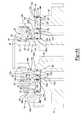
- FIG. 1is a cross-sectional view of a compressor including a non-orbiting scroll member and a capacity modulation assembly according to the present disclosure
- FIG. 2 ais a cross-sectional view of the non-orbiting scroll member and capacity modulation assembly of FIG. 1 showing the capacity modulation assembly in a full-capacity mode;
- FIG. 2 bis a cross-sectional view of the non-orbiting scroll member and capacity modulation assembly of FIG. 1 showing the capacity modulation assembly in a full-capacity mode;
- FIG. 3 ais a cross-sectional view of the non-orbiting scroll member and capacity modulation assembly of FIG. 1 showing the capacity modulation assembly in a partial reduced-capacity mode;
- FIG. 3 bis a cross-sectional view of the non-orbiting scroll member and capacity modulation assembly of FIG. 1 showing the capacity modulation assembly in a partial reduced-capacity mode;
- FIG. 4 ais a cross-sectional view of the non-orbiting scroll member and capacity modulation assembly of FIG. 1 showing the capacity modulation assembly in a full reduced-capacity mode;
- FIG. 4 bis a cross-sectional view of the non-orbiting scroll member and capacity modulation assembly of FIG. 1 showing the capacity modulation assembly in a full reduced-capacity mode;
- FIG. 5is a partial cross-sectional view of the non-orbiting scroll member and capacity modulation assembly of FIG. 1 , showing a biasing member of the capacity modulation assembly;
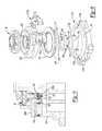
- FIG. 6is a perspective exploded view of the non-orbiting scroll member and capacity modulation assembly of FIG. 1 ;
- FIG. 7is a schematic illustration of the capacity modulation assembly of FIG. 1 in a full-capacity mode
- FIG. 8is a schematic illustration of the capacity modulation assembly of FIG. 1 in a partial reduced-capacity mode
- FIG. 9is a schematic illustration of the capacity modulation assembly of FIG. 1 in a full reduced-capacity mode.
- Example embodimentsare provided so that this disclosure will be thorough, and will fully convey the scope to those who are skilled in the art. Numerous specific details are set forth such as examples of specific components, devices, and methods, to provide a thorough understanding of embodiments of the present disclosure. It will be apparent to those skilled in the art that specific details need not be employed, that example embodiments may be embodied in many different forms and that neither should be construed to limit the scope of the disclosure. In some example embodiments, well-known processes, well-known device structures, and well-known technologies are not described in detail.
- first, second, third, etc.may be used herein to describe various elements, components, regions, layers and/or sections, these elements, components, regions, layers and/or sections should not be limited by these terms. These terms may be only used to distinguish one element, component, region, layer or section from another region, layer or section. Terms such as “first,” “second,” and other numerical terms when used herein do not imply a sequence or order unless clearly indicated by the context. Thus, a first element, component, region, layer or section discussed below could be termed a second element, component, region, layer or section without departing from the teachings of the example embodiments.
- Spatially relative termssuch as “inner,” “outer,” “beneath,” “below,” “lower,” “above,” “upper,” and the like, may be used herein for ease of description to describe one element or feature's relationship to another element(s) or feature(s) as illustrated in the figures. Spatially relative terms may be intended to encompass different orientations of the device in use or operation in addition to the orientation depicted in the figures. For example, if the device in the figures is turned over, elements described as “below” or “beneath” other elements or features would then be oriented “above” the other elements or features. Thus, the example term “below” can encompass both an orientation of above and below. The device may be otherwise oriented (rotated 90 degrees or at other orientations) and the spatially relative descriptors used herein interpreted accordingly.
- a compressor 10is shown as a hermetic scroll refrigerant-compressor of the low-side type, i.e., where the motor and compressor are cooled by suction gas in the hermetic shell, as illustrated in the vertical section shown in FIG. 1 .
- compressor 10is provided and may include a hermetic shell assembly 12 , a bearing housing assembly 14 , a motor assembly 16 , a compression mechanism 18 , a seal assembly 20 , a refrigerant discharge fitting 22 , a discharge valve assembly 24 , a suction gas inlet fitting 26 , and a capacity modulation assembly 28 .
- shell assembly 12houses bearing housing assembly 14 , motor assembly 16 , compression mechanism 18 , and capacity modulation assembly 28 .
- Shell assembly 12may generally form a compressor housing and may include a cylindrical shell 29 , an end cap 32 at the upper end thereof, a transversely extending partition 34 , and a base 36 at a lower end thereof. End cap 32 and partition 34 may generally define a discharge chamber 38 . Discharge chamber 38 may generally form a discharge muffler for compressor 10 . While illustrated as including discharge chamber 38 , it is understood that the present disclosure applies equally to direct-discharge configurations.
- Refrigerant discharge fitting 22may be attached to shell assembly 12 at an opening 40 in end cap 32 .
- Discharge valve assembly 24may be located within discharge fitting 22 and may generally prevent a reverse-flow condition.
- Suction gas inlet fitting 26may be attached to shell assembly 12 .
- Partition 34may include a discharge passage 44 therethrough providing communication between compression mechanism 18 and discharge chamber 38 .
- Bearing housing assembly 14may be affixed to shell 29 at a plurality of points in any desirable manner, such as staking.
- Bearing housing assembly 14may include a main bearing housing 46 , a bearing 48 disposed therein, bushings 50 , and fasteners 52 .
- Main bearing housing 46may house bearing 48 therein and may define an annular flat thrust bearing surface 54 on an axial end surface thereof.
- Main bearing housing 46may include apertures (not shown) extending therethrough and receiving fasteners 52 .
- Motor assembly 16may generally include a motor stator 58 , a rotor 60 , and a drive shaft 62 .
- Motor stator 58may be press fit into shell 29 .
- Drive shaft 62may be rotatably driven by rotor 60 and may be rotatably supported within first bearing 48 .
- Rotor 60may be press fit on drive shaft 62 .
- Drive shaft 62may include an eccentric crank pin 64 having a flat 66 thereon.
- Compression mechanism 18may generally include an orbiting scroll 68 and a non-orbiting scroll 70 .
- Orbiting scroll 68may include an end plate 72 having a spiral vane or wrap 74 on the upper surface thereof and an annular flat thrust surface 76 on the lower surface. Thrust surface 76 may interface with annular flat thrust bearing surface 54 on main bearing housing 46 .
- a cylindrical hub 78may project downwardly from thrust surface 76 and may have a drive bushing 80 rotatably disposed therein.
- Drive bushing 80may include an inner bore in which crank pin 64 is drivingly disposed.
- Crank pin flat 66may drivingly engage a flat surface in a portion of the inner bore of drive bushing 80 to provide a radially compliant driving arrangement.
- An Oldham coupling 82may be engaged with the orbiting and non-orbiting scrolls 68 , 70 to prevent relative rotation therebetween.
- Non-orbiting scroll 70may include an end plate 84 defining a discharge passage 92 and having a spiral wrap 86 extending from a first side 87 thereof, an annular hub 88 extending from a second side 89 thereof opposite the first side, and a series of radially outwardly extending flanged portions 90 ( FIG. 1 ) engaged with fasteners 52 .
- Fasteners 52may rotationally fix non-orbiting scroll 70 relative to main bearing housing 46 while allowing axial displacement of non-orbiting scroll 70 relative to main bearing housing 46 .
- Spiral wraps 74 , 86may be meshingly engaged with one another defining pockets 94 , 96 , 98 , 100 , 102 , 104 ( FIG. 1 ). It is understood that pockets 94 , 96 , 98 , 100 , 102 , 104 change throughout compressor operation.
- a first pocket 94 in FIG. 1may define a suction pocket in communication with a suction pressure region 106 of compressor 10 operating at a suction pressure (P s ) and a second pocket 104 in FIG. 1 , may define a discharge pocket in communication with a discharge pressure region 108 of compressor 10 operating at a discharge pressure (P d ) via discharge passage 92 .
- Pockets 96 , 98 , 100 , 102 intermediate the first and second pockets 94 , 104 in FIG. 1may form intermediate compression pockets operating at intermediate pressures between the suction pressure (P s ) and the discharge pressure (P d ).
- end plate 84may additionally include a biasing passage 110 , first and second modulation ports 112 a , 112 b and third and fourth modulation ports 114 a , 114 b .
- Biasing passage 110 , first and second modulation ports 112 a , 112 b ( FIG. 2A ), and third and fourth modulation ports 114 a , 114 b ( FIG. 2B )may each be in fluid communication with one of the intermediate compression pockets 96 , 98 , 100 , 102 .
- Biasing passage 110may be in fluid communication with one of the intermediate compression pockets operating at a higher pressure than ones of intermediate compression pockets in fluid communication with first, second, third and fourth modulation ports 112 a , 112 b , 114 a , 114 b .
- Third and fourth modulation ports 114 a , 114 bmay be in fluid communication with ones of the intermediate compression pockets operating at a higher pressure than ones of the intermediate compression pockets in fluid communication with first and second modulation ports 112 a , 112 b.
- Annular hub 88may include first and second portions 116 , 118 axially spaced from one another forming a stepped region 120 therebetween.
- First portion 116may be located axially between second portion 118 and end plate 84 and may have an outer radial surface 122 defining a first diameter (D 1 ) greater than or equal to a second diameter (D 2 ) defined by an outer radial surface 124 of second portion 118 .
- Capacity modulation assembly 28may include a first modulation valve ring 126 a , a second modulation valve ring 126 b , a modulation lift ring 128 , a retaining ring 130 , a first modulation control valve assembly 132 a , and a second modulation control valve assembly 132 b.
- First modulation valve ring 126 amay include an inner radial surface 134 , an outer radial surface 136 , a first axial end surface 138 defining an annular recess 140 and a valve portion 142 , first and second passages 144 a , 144 b , and third and fourth passages 146 a , 146 b .
- Inner radial surface 134may include first, second, and third portions 148 a , 148 b , 148 c .
- the first and second portions 148 a , 148 bmay define a second axial end surface 152 therebetween while the second and third portions 148 b , 148 c may define a third axial end surface 153 .
- First portion 148 amay define a third diameter (D 3 ) greater than a fourth diameter (D 4 ) defined by the second portion 148 b .
- Third portion 148 cmay define a fifth diameter (D 5 ) greater than the fourth diameter (D 4 ) and greater than the third diameter (D 3 ).
- the first and fourth diameters (D 1 , D 4 )may be approximately equal to one another and the first portion 116 of hub 88 may be sealingly engaged with the second portion 148 b of first modulation valve ring 126 a via a seal 154 located radially therebetween.
- seal 154may include an o-ring seal and may be located within an annular recess 156 in second portion 148 b of first modulation valve ring 126 a .
- ring seal 154could be located in an annular recess (not shown) in annular hub 88 .
- Second modulation valve ring 126 bmay be located radially between outer radial surface 122 and the first portion 148 a of inner radial surface 134 , and located axially between the second axial end surface 152 and the second side 89 of end plate 84 . Accordingly, the second modulation valve ring 126 b may be an annular body defining inner and outer radial surfaces 155 a , 155 b , and first and second axial end surfaces 157 a , 157 b .
- Inner and outer radial surfaces 155 a , 155 bmay be sealingly engaged with outer radial surface 122 of annular hub 88 and with first portion 148 a of inner radial surface 134 , respectively, via first and second seals 163 a , 163 b . More specifically, first and second seals 163 a , 163 b may include o-ring seals and may be located within respective annular recesses 165 a , 165 b formed in inner radial surface 155 a of second modulation valve ring 126 b and formed in first portion 148 a of inner radial surface 134 , respectively.
- First modulation valve ring 126 a and second modulation valve ring 126 bmay cooperate to define a first modulation control chamber 174 a between the second axial end surface 152 of the first modulation valve ring 126 a and the first axial end surface 157 a of the second modulation valve ring 126 b .
- Third passage 146 amay be in fluid communication with first modulation control chamber 174 a.
- the second axial end surface 157 b of second modulation valve ring 126 bmay include a series of bores 167 and a series of biasing members 169 respectively disposed in the series of bores 167 .
- the biasing members 169may be helical springs that bias the second modulation valve ring 126 b in an axial direction away from the end plate 84 . More specifically, the biasing members 169 may provide a first axial force (F 1 ) between the non-orbiting scroll 70 and the second modulation valve ring 126 b , urging the second modulation valve ring 126 b axially away from non-orbiting scroll 70 .
- second axial end surface 157 bincludes four bores 167 and four biasing members 169 . While the second axial end surface 157 b is described as including four bores 167 and four biasing members 169 , the second axial end surface 157 b may include any number of bores 167 and any number of biasing members 169 .
- modulation lift ring 128may be located within annular recess 140 and may include an annular body defining inner and outer radial surfaces 158 , 160 , and first and second axial end surfaces 159 , 161 .
- Inner and outer radial surfaces 158 , 160may be sealingly engaged with inner and outer sidewalls 162 , 164 of annular recess 140 via first and second seals 166 , 168 , respectively.
- first and second seals 166 , 168may include o-ring seals and may be located within annular recesses 170 , 172 in inner and outer radial surfaces 158 , 160 of modulation lift ring 128 .
- First modulation valve ring 126 a and modulation lift ring 128may cooperate to define a second modulation control chamber 174 b between annular recess 140 and first axial end surface 159 of modulation lift ring 128 .
- First passage 144 amay be in fluid communication with second modulation control chamber 174 b .
- second axial end surface 161 of modulation lift ring 128may face end plate 84 and may include a series of protrusions 177 defining radial flow passages 178 therebetween.
- Seal assembly 20may form a floating seal assembly and may be sealingly engaged with non-orbiting scroll 70 and first modulation valve ring 126 a to define an axial biasing chamber 180 . More specifically, seal assembly 20 may be sealingly engaged with outer radial surface 124 of annular hub 88 and third portion 148 c of first modulation valve ring 126 a . Axial biasing chamber 180 may be defined axially between an axial end surface 182 of seal assembly 20 and third axial end surface 153 of first modulation valve ring 126 a . Second passage 144 b and fourth passage 146 b may be in fluid communication with axial biasing chamber 180 .
- Retaining ring 130may be axially fixed relative to non-orbiting scroll 70 and may be located within axial biasing chamber 180 . More specifically, retaining ring 130 may be located within a recess 117 in first portion 116 of annular hub 88 axially between seal assembly 20 and first modulation valve ring 126 a . Retaining ring 130 may form an axial stop for first modulation valve ring 126 a.
- First modulation control valve assembly 132 amay include a solenoid-operated valve and may be in fluid communication with first and second passages 144 a , 144 b in first modulation valve ring 126 a and with suction pressure region 106 .
- Second modulation control valve assembly 132 bmay include a solenoid-operated valve and may be in fluid communication with third and fourth passages 146 a , 146 b in first modulation valve ring 126 a and with suction pressure region 106 .
- first and second modulation control valve assemblies 132 a , 132 bmay each be operated in first and second modes. Accordingly, the compressor 10 may be operated in at least three modes of operation.
- FIGS. 7 through 9schematically illustrate operation of first modulation control valve assembly 132 a and second modulation control valve assembly 132 a in three modes of operation.
- first modulation control valve assembly 132 amay provide fluid communication between second modulation control chamber 174 b and suction pressure region 106
- second modulation control valve assembly 132 bmay provide fluid communication between first modulation control chamber 174 a and axial biasing chamber 180
- first modulation control valve assembly 132 amay provide fluid communication between first passage 144 a and suction pressure region 106
- second modulation control valve assembly 132 bmay provide fluid communication between third passage 146 a , fourth passage 146 b , and axial biasing chamber 180 .
- first modulation control valve assembly 132 amay provide fluid communication between second modulation control chamber 174 b and axial biasing chamber 180
- second modulation control valve assembly 132 bmay provide fluid communication between first modulation control chamber 174 a and axial biasing chamber 180
- first modulation control valve assembly 132 amay provide fluid communication between first and second passages 144 a , 144 b during operation in the second mode.
- first modulation control valve assembly 132 amay provide fluid communication between second modulation control chamber 174 b and axial biasing chamber 180
- second modulation control valve assembly 132 bmay provide fluid communication between first modulation control chamber 174 a and suction pressure region 106
- second modulation control valve assembly 132 amay provide fluid communication between third passage 146 a and suction pressure region 106 .
- Inner sidewall 162may define a diameter (D 6 ) less than a diameter (D 7 ) defined by outer sidewall 164 .
- First radial surface area (A 1 )may be less than second radial surface area (A 2 ).
- First modulation valve ring 126 amay be displaced between first and second positions based on the pressure provided to second modulation control chamber 174 b by first modulation control valve assembly 132 a .
- First modulation valve ring 126 amay be displaced by fluid pressure acting directly thereon, as discussed below.
- Third radial surface area (A 3 )may be less than second radial surface area (A 2 ).
- first and second modulation valve rings 126 a , 126 bmay each be in respective first positions ( FIGS. 2A and 2B ).
- a first intermediate pressure (P i1 ) within axial biasing chamber 180 applied to first radial surface area (A 1 )may provide a second axial force (F 2 ) operating in a direction opposite the first axial force (F 1 ), urging first modulation valve ring 126 a axially toward non-orbiting scroll 70 .
- the first intermediate pressure (P i1 )is supplied to the axial biasing chamber 180 via biasing passage 110 .
- Suction pressure (P s ) within second modulation control chamber 174 bmay provide a third axial force (F 3 ) opposite the second axial force (F 2 ), and first intermediate pressure (P i1 ) within first modulation control chamber 174 a may provide a fourth axial force (F 4 ) opposite the second axial force (F 2 ).
- Suction pressure (P s )is supplied to second modulation control chamber 174 b via control valve assembly 132 a and first passage 144 a while first intermediate pressure (P i1 ) is supplied via control valve assembly 132 b , third passage 146 a , and fourth passage 146 b to first modulation control chamber 174 a.
- the third and fourth axial forces (F 3 , F 4 )may urge first modulation valve ring 126 a axially away from non-orbiting scroll 70 .
- second axial force (F 2 )may be greater than the combined third and fourth axial forces (F 3 , F 4 ) even though biasing chamber 180 and control chamber 174 a are both at intermediate pressure (P i1 ) because second radial surface (A 2 ) is greater than third radial surface area (A 3 ) and control chamber 174 b is at suction pressure (P s ), which is less than intermediate pressure (P i1 ).
- Fourth axial force (F 4 )may be greater than the first axial force (F 1 ).
- first and second modulation valve rings 126 a , 126 bmay each be in the respective first position ( FIGS. 2A and 2B ) during operation of first and second modulation control valve assemblies 132 a , 132 b in the first mode.
- the first positionmay include valve portion 142 of first modulation valve ring 126 a abutting end plate 84 and closing first and second modulation ports 112 a , 112 b , and second modulation valve ring 126 b abutting end plate 84 and closing third and fourth modulation ports 114 a , 114 b .
- This positionplaces the compressor 10 in a full-capacity state, as each port 112 a , 112 b , 114 a , 114 b is closed, thereby allowing each pocket 94 - 104 to fully compress fluid disposed therein.
- first modulation valve ring 126 aWhen first and second modulation control valve assemblies 132 a , 132 b are operated in the second mode, first modulation valve ring 126 a may be in a second position, and second modulation valve ring 126 b may be in the first position ( FIGS. 3A, 3B ).
- first intermediate pressure (P i1 ) within second modulation control chamber 174 bmay provide a fifth axial force (F 5 ) acting on first modulation valve ring 126 a and opposite second axial force (F 2 ) urging first modulation valve ring 126 a axially away from non-orbiting scroll 70 .
- second modulation control chamber 174 b and axial biasing chamber 180are in fluid communication with one another during operation of the first modulation control valve assembly 132 a in the second mode ( FIG. 3A ) via passages 144 a , 144 b , both may operate at approximately the same first intermediate pressure (P i1 ).
- Fifth axial force (F 5 )may be greater than second axial force (F 2 ), however, because second radial surface area (A 2 ) is greater than first radial surface area (A 1 ). Therefore, first modulation valve ring 126 a may be in the second position ( FIG. 3A ) during operation of first modulation control valve assembly 132 a in the second mode.
- the second positionmay include valve portion 142 of first modulation valve ring 126 a being displaced from end plate 84 and opening first and second modulation ports 112 a , 112 b .
- First modulation valve ring 126 amay abut retaining ring 130 when in the second position, as control chamber 174 a is at first intermediate pressure (P i1 ) via passages 146 a , 146 b of control valve assembly 132 a ( FIG. 3B ).
- First modulation valve ring 126 a and modulation lift ring 128may be forced in axial directions opposite one another during operation of first and second modulation control valve assemblies 132 a , 132 b in the second mode ( FIGS. 3A and 3B ). More specifically, first modulation valve ring 126 a may be displaced axially away from end plate 84 and modulation lift ring 128 may be urged axially toward end plate 84 . Protrusions 177 of modulation lift ring 128 may abut end plate 84 and first and second modulation ports 112 a , 112 b may be in fluid communication with suction pressure region 106 via radial flow passages 178 when first modulation valve ring 126 a is in the second position.
- the compressor 10When the valve assemblies 132 a , 132 b are operated in the second mode ( FIGS. 3A and 3B ), the compressor 10 is in a reduced-capacity state, as ports 112 a , 112 b are opened, thereby preventing the pockets associated with ports 112 a , 112 b from fully compressing a fluid disposed therein. Operation of the compressor 10 in this state results in operation of the compressor 10 at approximately seventy percent (70%) of total compressor capacity.
- first and second modulation valve rings 126 a , 126 bmay each be in their respective second positions ( FIGS. 4A, 4B ).
- suction pressure (P s ) within first modulation control chamber 174 amay provide a sixth axial force (F 6 ) acting on second modulation valve ring 126 b and opposite first axial force (F 1 ) of the biasing members 169 .
- Suction pressure (P s )is supplied to chamber 174 a via third passage 146 a of valve assembly 132 a .
- First axial force (F 1 )may be greater than sixth axial force (F 6 ), therefore urging second modulation valve ring 126 b axially away from non-orbiting scroll 70 under the force of biasing members 169 .
- second modulation control chamber 174 bmay be at first intermediate pressure (P i1 ), providing the fifth axial force (F 5 ) acting on first modulation valve ring 126 a , as described above with respect to the second mode of operation. Therefore, first and second modulation valve rings 126 a , 126 b may each be in their respective second positions during operation of first and second modulation control valve assemblies 132 a , 132 b in the third mode.
- the second position of first modulation valve ring 126 amay include valve portion 142 being displaced from end plate 84 and opening first and second modulation ports 112 a , 112 b .
- the second position of second modulation valve ring 126 bmay include the first axial end surface 157 b being displaced from end plate 84 and opening third and fourth modulation ports 114 a , 114 b .
- Third and fourth modulation ports 114 a , 114 bmay be in fluid communication with suction pressure region 106 via radial flow passages 178 when first and second modulation valve rings 126 a , 126 b are each in their respective second positions.
- valve assemblies 132 a , 132 bWhen the valve assemblies 132 a , 132 b are in the third mode, the compressor 10 is in a reduced-capacity mode, as each modulation port 112 a , 112 b , 114 a , 114 b is opened, thereby preventing the associated pocket from fully compressing a fluid disposed therein.
- a capacity of the compressor 10is less than the capacity of the compressor 10 when the valve assemblies 132 a , 132 b are in the second mode.
- compressor capacitymay be at approximately fifty percent (50%) of total compressor capacity.
Landscapes
- Engineering & Computer Science (AREA)
- Mechanical Engineering (AREA)
- General Engineering & Computer Science (AREA)
- Physics & Mathematics (AREA)
- Fluid Mechanics (AREA)
- Rotary Pumps (AREA)
Abstract
Description
Claims (20)
Priority Applications (1)
| Application Number | Priority Date | Filing Date | Title |
|---|---|---|---|
| US15/682,044US9976554B2 (en) | 2014-05-15 | 2017-08-21 | Capacity-modulated scroll compressor |
Applications Claiming Priority (2)
| Application Number | Priority Date | Filing Date | Title |
|---|---|---|---|
| US14/278,325US9739277B2 (en) | 2014-05-15 | 2014-05-15 | Capacity-modulated scroll compressor |
| US15/682,044US9976554B2 (en) | 2014-05-15 | 2017-08-21 | Capacity-modulated scroll compressor |
Related Parent Applications (1)
| Application Number | Title | Priority Date | Filing Date |
|---|---|---|---|
| US14/278,325ContinuationUS9739277B2 (en) | 2014-05-15 | 2014-05-15 | Capacity-modulated scroll compressor |
Publications (2)
| Publication Number | Publication Date |
|---|---|
| US20170342978A1 US20170342978A1 (en) | 2017-11-30 |
| US9976554B2true US9976554B2 (en) | 2018-05-22 |
Family
ID=54523701
Family Applications (2)
| Application Number | Title | Priority Date | Filing Date |
|---|---|---|---|
| US14/278,325Active2035-10-29US9739277B2 (en) | 2014-05-15 | 2014-05-15 | Capacity-modulated scroll compressor |
| US15/682,044ActiveUS9976554B2 (en) | 2014-05-15 | 2017-08-21 | Capacity-modulated scroll compressor |
Family Applications Before (1)
| Application Number | Title | Priority Date | Filing Date |
|---|---|---|---|
| US14/278,325Active2035-10-29US9739277B2 (en) | 2014-05-15 | 2014-05-15 | Capacity-modulated scroll compressor |
Country Status (2)
| Country | Link |
|---|---|
| US (2) | US9739277B2 (en) |
| CN (2) | CN204783641U (en) |
Families Citing this family (26)
| Publication number | Priority date | Publication date | Assignee | Title |
|---|---|---|---|---|
| US7988433B2 (en) | 2009-04-07 | 2011-08-02 | Emerson Climate Technologies, Inc. | Compressor having capacity modulation assembly |
| US9249802B2 (en) | 2012-11-15 | 2016-02-02 | Emerson Climate Technologies, Inc. | Compressor |
| US9651043B2 (en) | 2012-11-15 | 2017-05-16 | Emerson Climate Technologies, Inc. | Compressor valve system and assembly |
| US9435340B2 (en) | 2012-11-30 | 2016-09-06 | Emerson Climate Technologies, Inc. | Scroll compressor with variable volume ratio port in orbiting scroll |
| US9739277B2 (en)* | 2014-05-15 | 2017-08-22 | Emerson Climate Technologies, Inc. | Capacity-modulated scroll compressor |
| US9989057B2 (en) | 2014-06-03 | 2018-06-05 | Emerson Climate Technologies, Inc. | Variable volume ratio scroll compressor |
| US9790940B2 (en) | 2015-03-19 | 2017-10-17 | Emerson Climate Technologies, Inc. | Variable volume ratio compressor |
| US10378540B2 (en) | 2015-07-01 | 2019-08-13 | Emerson Climate Technologies, Inc. | Compressor with thermally-responsive modulation system |
| CN207377799U (en) | 2015-10-29 | 2018-05-18 | 艾默生环境优化技术有限公司 | Compressor |
| US10890186B2 (en) | 2016-09-08 | 2021-01-12 | Emerson Climate Technologies, Inc. | Compressor |
| US10801495B2 (en) | 2016-09-08 | 2020-10-13 | Emerson Climate Technologies, Inc. | Oil flow through the bearings of a scroll compressor |
| US11168685B2 (en) | 2016-11-17 | 2021-11-09 | Emerson Climate Technologies (Suzhou) Co., Ltd. | Dual-vane scroll compressor with capacity modulation |
| KR102407415B1 (en)* | 2017-02-01 | 2022-06-10 | 엘지전자 주식회사 | Scroll compressor |
| US10753352B2 (en) | 2017-02-07 | 2020-08-25 | Emerson Climate Technologies, Inc. | Compressor discharge valve assembly |
| US11022119B2 (en) | 2017-10-03 | 2021-06-01 | Emerson Climate Technologies, Inc. | Variable volume ratio compressor |
| US10962008B2 (en) | 2017-12-15 | 2021-03-30 | Emerson Climate Technologies, Inc. | Variable volume ratio compressor |
| US10995753B2 (en) | 2018-05-17 | 2021-05-04 | Emerson Climate Technologies, Inc. | Compressor having capacity modulation assembly |
| US11656003B2 (en) | 2019-03-11 | 2023-05-23 | Emerson Climate Technologies, Inc. | Climate-control system having valve assembly |
| US11655813B2 (en) | 2021-07-29 | 2023-05-23 | Emerson Climate Technologies, Inc. | Compressor modulation system with multi-way valve |
| US12259163B2 (en) | 2022-06-01 | 2025-03-25 | Copeland Lp | Climate-control system with thermal storage |
| US11846287B1 (en) | 2022-08-11 | 2023-12-19 | Copeland Lp | Scroll compressor with center hub |
| US11965507B1 (en) | 2022-12-15 | 2024-04-23 | Copeland Lp | Compressor and valve assembly |
| US12416308B2 (en) | 2022-12-28 | 2025-09-16 | Copeland Lp | Compressor with shutdown assembly |
| KR102770848B1 (en)* | 2023-01-12 | 2025-02-24 | 엘지전자 주식회사 | Scroll compressor |
| US12173708B1 (en) | 2023-12-07 | 2024-12-24 | Copeland Lp | Heat pump systems with capacity modulation |
| US12163523B1 (en) | 2023-12-15 | 2024-12-10 | Copeland Lp | Compressor and valve assembly |
Citations (24)
| Publication number | Priority date | Publication date | Assignee | Title |
|---|---|---|---|---|
| US5640854A (en)* | 1995-06-07 | 1997-06-24 | Copeland Corporation | Scroll machine having liquid injection controlled by internal valve |
| US5674058A (en)* | 1994-06-08 | 1997-10-07 | Nippondenso Co., Ltd. | Scroll-type refrigerant compressor |
| US5678985A (en)* | 1995-12-19 | 1997-10-21 | Copeland Corporation | Scroll machine with capacity modulation |
| US5722257A (en)* | 1995-10-11 | 1998-03-03 | Denso Corporation | Compressor having refrigerant injection ports |
| US5741120A (en)* | 1995-06-07 | 1998-04-21 | Copeland Corporation | Capacity modulated scroll machine |
| US5855475A (en)* | 1995-12-05 | 1999-01-05 | Matsushita Electric Industrial Co., Ltd. | Scroll compressor having bypass valves |
| US5885063A (en)* | 1996-05-07 | 1999-03-23 | Matshushita Electric Industrial Co., Ltd. | Variable capacity scroll compressor |
| US5993171A (en)* | 1996-06-25 | 1999-11-30 | Sanden Corporation | Scroll-type compressor with variable displacement mechanism |
| US5993177A (en)* | 1996-05-21 | 1999-11-30 | Sanden Corporation | Scroll type compressor with improved variable displacement mechanism |
| US6047557A (en)* | 1995-06-07 | 2000-04-11 | Copeland Corporation | Adaptive control for a refrigeration system using pulse width modulated duty cycle scroll compressor |
| US6095765A (en)* | 1998-03-05 | 2000-08-01 | Carrier Corporation | Combined pressure ratio and pressure differential relief valve |
| US6102671A (en)* | 1997-09-04 | 2000-08-15 | Matsushita Electric Industrial Co., Ltd. | Scroll compressor |
| US6123517A (en)* | 1997-11-24 | 2000-09-26 | Copeland Corporation | Scroll machine with capacity modulation |
| US6139287A (en)* | 1995-12-19 | 2000-10-31 | Daikin Industries, Ltd. | Scroll type fluid machine |
| US6149401A (en)* | 1997-10-27 | 2000-11-21 | Denso Corporation | Variable discharge-amount compressor for refrigerant cycle |
| US6164940A (en)* | 1998-09-11 | 2000-12-26 | Sanden Corporation | Scroll type compressor in which a soft starting mechanism is improved with a simple structure |
| US6176686B1 (en)* | 1999-02-19 | 2001-01-23 | Copeland Corporation | Scroll machine with capacity modulation |
| US6202438B1 (en)* | 1999-11-23 | 2001-03-20 | Scroll Technologies | Compressor economizer circuit with check valve |
| US6210120B1 (en)* | 1999-03-19 | 2001-04-03 | Scroll Technologies | Low charge protection vent |
| US6213731B1 (en)* | 1999-09-21 | 2001-04-10 | Copeland Corporation | Compressor pulse width modulation |
| US6231316B1 (en)* | 1998-07-01 | 2001-05-15 | Denso Corporation | Scroll-type variable-capacity compressor |
| US6273691B1 (en)* | 1996-07-22 | 2001-08-14 | Matsushita Electric Industrial Co., Ltd. | Scroll gas compressor having asymmetric bypass holes |
| US6293776B1 (en)* | 2000-07-12 | 2001-09-25 | Scroll Technologies | Method of connecting an economizer tube |
| US6293767B1 (en)* | 2000-02-28 | 2001-09-25 | Copeland Corporation | Scroll machine with asymmetrical bleed hole |
Family Cites Families (129)
| Publication number | Priority date | Publication date | Assignee | Title |
|---|---|---|---|---|
| US4058988A (en) | 1976-01-29 | 1977-11-22 | Dunham-Bush, Inc. | Heat pump system with high efficiency reversible helical screw rotary compressor |
| JPS5481513A (en) | 1977-12-09 | 1979-06-29 | Hitachi Ltd | Scroll compressor |
| JPS5776287A (en) | 1980-10-31 | 1982-05-13 | Hitachi Ltd | Scroll compressor |
| US4383805A (en) | 1980-11-03 | 1983-05-17 | The Trane Company | Gas compressor of the scroll type having delayed suction closing capacity modulation |
| US4389171A (en) | 1981-01-15 | 1983-06-21 | The Trane Company | Gas compressor of the scroll type having reduced starting torque |
| JPS58148290A (en) | 1982-02-26 | 1983-09-03 | Hitachi Ltd | Refrigerator with acroll compressor |
| US4545742A (en) | 1982-09-30 | 1985-10-08 | Dunham-Bush, Inc. | Vertical axis hermetic helical screw rotary compressor with discharge gas oil mist eliminator and dual transfer tube manifold for supplying liquid refrigerant and refrigerant vapor to the compression area |
| US4497615A (en) | 1983-07-25 | 1985-02-05 | Copeland Corporation | Scroll-type machine |
| JPS60259794A (en) | 1984-06-04 | 1985-12-21 | Hitachi Ltd | Heat pump type air conditioner |
| US4609329A (en) | 1985-04-05 | 1986-09-02 | Frick Company | Micro-processor control of a movable slide stop and a movable slide valve in a helical screw rotary compressor with an enconomizer inlet port |
| JPS61265381A (en) | 1985-05-20 | 1986-11-25 | Hitachi Ltd | Gas injector for screw compressor |
| JPH0641756B2 (en) | 1985-06-18 | 1994-06-01 | サンデン株式会社 | Variable capacity scroll type compressor |
| JPS62197684A (en) | 1986-02-26 | 1987-09-01 | Hitachi Ltd | scroll compressor |
| US4877382A (en) | 1986-08-22 | 1989-10-31 | Copeland Corporation | Scroll-type machine with axially compliant mounting |
| JP2631649B2 (en) | 1986-11-27 | 1997-07-16 | 三菱電機株式会社 | Scroll compressor |
| JPH0830471B2 (en) | 1986-12-04 | 1996-03-27 | 株式会社日立製作所 | Air conditioner equipped with an inverter-driven scroll compressor |
| JPH0744775Y2 (en) | 1987-03-26 | 1995-10-11 | 三菱重工業株式会社 | Compressor capacity control device |
| JPH0746787Y2 (en) | 1987-12-08 | 1995-10-25 | サンデン株式会社 | Variable capacity scroll compressor |
| JPH0794832B2 (en) | 1988-08-12 | 1995-10-11 | 三菱重工業株式会社 | Rotary compressor |
| US5055012A (en) | 1988-08-31 | 1991-10-08 | Kabushiki Kaisha Toshiba | Scroll compressor with bypass release passage in stationary scroll member |
| JP2780301B2 (en) | 1989-02-02 | 1998-07-30 | 株式会社豊田自動織機製作所 | Variable capacity mechanism for scroll compressor |
| JPH0381588A (en) | 1989-08-23 | 1991-04-05 | Hitachi Ltd | Scroll compressor capacity control device |
| US5055010A (en) | 1990-10-01 | 1991-10-08 | Copeland Corporation | Suction baffle for refrigeration compressor |
| CA2052350C (en) | 1990-11-14 | 2000-01-18 | Takayuki Iio | Scroll type compressor |
| JP2796427B2 (en) | 1990-11-14 | 1998-09-10 | 三菱重工業株式会社 | Scroll compressor |
| JPH04117195U (en) | 1991-04-02 | 1992-10-20 | サンデン株式会社 | scroll compressor |
| US5080056A (en) | 1991-05-17 | 1992-01-14 | General Motors Corporation | Thermally sprayed aluminum-bronze coatings on aluminum engine bores |
| US5240389A (en) | 1991-07-26 | 1993-08-31 | Kabushiki Kaisha Toshiba | Scroll type compressor |
| US5169294A (en) | 1991-12-06 | 1992-12-08 | Carrier Corporation | Pressure ratio responsive unloader |
| JP2831193B2 (en) | 1992-02-06 | 1998-12-02 | 三菱重工業株式会社 | Capacity control mechanism of scroll compressor |
| JP3100452B2 (en) | 1992-02-18 | 2000-10-16 | サンデン株式会社 | Variable capacity scroll compressor |
| DE4205140C1 (en) | 1992-02-20 | 1993-05-27 | Braas Gmbh, 6370 Oberursel, De | |
| US5451146A (en) | 1992-04-01 | 1995-09-19 | Nippondenso Co., Ltd. | Scroll-type variable-capacity compressor with bypass valve |
| US5363821A (en) | 1993-07-06 | 1994-11-15 | Ford Motor Company | Thermoset polymer/solid lubricant coating system |
| US5607288A (en) | 1993-11-29 | 1997-03-04 | Copeland Corporation | Scroll machine with reverse rotation protection |
| JPH07293456A (en) | 1994-04-28 | 1995-11-07 | Sanyo Electric Co Ltd | Scroll compressor |
| JP3376692B2 (en) | 1994-05-30 | 2003-02-10 | 株式会社日本自動車部品総合研究所 | Scroll compressor |
| JPH07332262A (en) | 1994-06-03 | 1995-12-22 | Toyota Autom Loom Works Ltd | Scroll type compressor |
| US5613841A (en) | 1995-06-07 | 1997-03-25 | Copeland Corporation | Capacity modulated scroll machine |
| US5551846A (en) | 1995-12-01 | 1996-09-03 | Ford Motor Company | Scroll compressor capacity control valve |
| JP3750169B2 (en) | 1995-12-27 | 2006-03-01 | ダイキン工業株式会社 | Hermetic compressor |
| JP3874469B2 (en) | 1996-10-04 | 2007-01-31 | 株式会社日立製作所 | Scroll compressor |
| JPH10311286A (en) | 1997-05-12 | 1998-11-24 | Matsushita Electric Ind Co Ltd | Capacity control scroll compressor |
| JP3731287B2 (en) | 1997-05-12 | 2006-01-05 | 松下電器産業株式会社 | Capacity control scroll compressor |
| JPH1182334A (en) | 1997-09-09 | 1999-03-26 | Sanden Corp | Scroll type compressor |
| JP3602700B2 (en) | 1997-10-06 | 2004-12-15 | 松下電器産業株式会社 | Compressor injection device |
| JPH11264383A (en) | 1998-03-19 | 1999-09-28 | Hitachi Ltd | Positive displacement fluid machinery |
| US6478550B2 (en) | 1998-06-12 | 2002-11-12 | Daikin Industries, Ltd. | Multi-stage capacity-controlled scroll compressor |
| JP2000104684A (en) | 1998-09-29 | 2000-04-11 | Nippon Soken Inc | Variable displacement compressor |
| JP2000161263A (en) | 1998-11-27 | 2000-06-13 | Mitsubishi Electric Corp | Capacity control scroll compressor |
| JP2000329078A (en) | 1999-05-20 | 2000-11-28 | Fujitsu General Ltd | Scroll compressor |
| JP2000352386A (en) | 1999-06-08 | 2000-12-19 | Mitsubishi Heavy Ind Ltd | Scroll compressor |
| JP2000356194A (en) | 1999-06-11 | 2000-12-26 | Mitsubishi Heavy Ind Ltd | Scroll type fluid machine |
| JP2001329967A (en) | 2000-05-24 | 2001-11-30 | Toyota Industries Corp | Seal structure of scroll type compressor |
| DE10027990A1 (en) | 2000-06-08 | 2001-12-20 | Luk Fahrzeug Hydraulik | Vane or roller pump has intermediate hydraulic capacity which can be pressurized via connection to pressure connection |
| US6350111B1 (en) | 2000-08-15 | 2002-02-26 | Copeland Corporation | Scroll machine with ported orbiting scroll member |
| JP2002089462A (en) | 2000-09-13 | 2002-03-27 | Toyota Industries Corp | Scroll type compressor and seal method for scroll type compressor |
| JP2002089468A (en) | 2000-09-14 | 2002-03-27 | Toyota Industries Corp | Scroll type compressor |
| JP2002089463A (en) | 2000-09-18 | 2002-03-27 | Toyota Industries Corp | Scroll type compressor |
| JP2002106483A (en) | 2000-09-29 | 2002-04-10 | Toyota Industries Corp | Scroll type compressor and sealing method therefor |
| JP2002106482A (en) | 2000-09-29 | 2002-04-10 | Toyota Industries Corp | Scroll type compressor and gas compression method |
| US6412293B1 (en) | 2000-10-11 | 2002-07-02 | Copeland Corporation | Scroll machine with continuous capacity modulation |
| US6419457B1 (en) | 2000-10-16 | 2002-07-16 | Copeland Corporation | Dual volume-ratio scroll machine |
| US6679683B2 (en) | 2000-10-16 | 2004-01-20 | Copeland Corporation | Dual volume-ratio scroll machine |
| US6413058B1 (en) | 2000-11-21 | 2002-07-02 | Scroll Technologies | Variable capacity modulation for scroll compressor |
| US6457948B1 (en) | 2001-04-25 | 2002-10-01 | Copeland Corporation | Diagnostic system for a compressor |
| JP2003074482A (en) | 2001-08-31 | 2003-03-12 | Sanyo Electric Co Ltd | Scroll compressor |
| JP2003074481A (en) | 2001-08-31 | 2003-03-12 | Sanyo Electric Co Ltd | Scroll compressor |
| US6537043B1 (en) | 2001-09-05 | 2003-03-25 | Copeland Corporation | Compressor discharge valve having a contoured body with a uniform thickness |
| FR2830291B1 (en) | 2001-09-28 | 2004-04-16 | Danfoss Maneurop S A | SPIRAL COMPRESSOR, OF VARIABLE CAPACITY |
| KR100421393B1 (en) | 2002-01-10 | 2004-03-09 | 엘지전자 주식회사 | Apparatus for preventing vacuum compression of scroll compressor |
| US6619936B2 (en) | 2002-01-16 | 2003-09-16 | Copeland Corporation | Scroll compressor with vapor injection |
| JP4310960B2 (en) | 2002-03-13 | 2009-08-12 | ダイキン工業株式会社 | Scroll type fluid machinery |
| US6830815B2 (en) | 2002-04-02 | 2004-12-14 | Ford Motor Company | Low wear and low friction coatings for articles made of low softening point materials |
| KR100434077B1 (en) | 2002-05-01 | 2004-06-04 | 엘지전자 주식회사 | Apparatus preventing vacuum for scroll compressor |
| KR100438621B1 (en) | 2002-05-06 | 2004-07-02 | 엘지전자 주식회사 | Apparatus for preventing vacuum compression of scroll compressor |
| JP2004156532A (en) | 2002-11-06 | 2004-06-03 | Toyota Industries Corp | Variable capacity mechanism in scroll compressor |
| KR100498309B1 (en) | 2002-12-13 | 2005-07-01 | 엘지전자 주식회사 | High-degree vacuum prevention apparatus for scroll compressor and assembly method for this apparatus |
| JP4007189B2 (en) | 2002-12-20 | 2007-11-14 | 株式会社豊田自動織機 | Scroll compressor |
| JP2004211567A (en) | 2002-12-27 | 2004-07-29 | Toyota Industries Corp | Displacement changing mechanism of scroll compressor |
| US6913448B2 (en) | 2002-12-30 | 2005-07-05 | Industrial Technology Research Institute | Load-regulating device for scroll type compressors |
| US7100386B2 (en) | 2003-03-17 | 2006-09-05 | Scroll Technologies | Economizer/by-pass port inserts to control port size |
| US6884042B2 (en) | 2003-06-26 | 2005-04-26 | Scroll Technologies | Two-step self-modulating scroll compressor |
| KR100557056B1 (en) | 2003-07-26 | 2006-03-03 | 엘지전자 주식회사 | Capacity adjustable scroll compressor |
| KR100547321B1 (en) | 2003-07-26 | 2006-01-26 | 엘지전자 주식회사 | Capacity adjustable scroll compressor |
| KR100547322B1 (en) | 2003-07-26 | 2006-01-26 | 엘지전자 주식회사 | Capacity adjustable scroll compressor |
| CN100371598C (en) | 2003-08-11 | 2008-02-27 | 三菱重工业株式会社 | Scroll compressor |
| KR100547323B1 (en) | 2003-09-15 | 2006-01-26 | 엘지전자 주식회사 | Scroll compressor |
| JP4892238B2 (en) | 2003-10-17 | 2012-03-07 | パナソニック株式会社 | Scroll compressor |
| TWI235791B (en) | 2003-12-25 | 2005-07-11 | Ind Tech Res Inst | Scroll compressor with self-sealing structure |
| US7070401B2 (en) | 2004-03-15 | 2006-07-04 | Copeland Corporation | Scroll machine with stepped sleeve guide |
| JP4722493B2 (en) | 2004-03-24 | 2011-07-13 | 株式会社日本自動車部品総合研究所 | Fluid machinery |
| KR100608664B1 (en) | 2004-03-25 | 2006-08-08 | 엘지전자 주식회사 | Variable capacity of scroll compressor |
| US7261527B2 (en) | 2004-04-19 | 2007-08-28 | Scroll Technologies | Compressor check valve retainer |
| US7029251B2 (en) | 2004-05-28 | 2006-04-18 | Rechi Precision Co., Ltd. | Backpressure mechanism of scroll type compressor |
| KR100652588B1 (en) | 2004-11-11 | 2006-12-07 | 엘지전자 주식회사 | Discharge Valve System of Scroll Compressor |
| US20060228243A1 (en) | 2005-04-08 | 2006-10-12 | Scroll Technologies | Discharge valve structures for a scroll compressor having a separator plate |
| US7429167B2 (en) | 2005-04-18 | 2008-09-30 | Emerson Climate Technologies, Inc. | Scroll machine having a discharge valve assembly |
| CN101171464B (en) | 2005-05-04 | 2011-11-23 | 开利公司 | Refrigerant system with variable speed scroll compressor and economizer circuit and operation method |
| WO2006132638A1 (en) | 2005-06-07 | 2006-12-14 | Carrier Corporation | Variable speed compressor motor control for low speed operation |
| US20070036661A1 (en) | 2005-08-12 | 2007-02-15 | Copeland Corporation | Capacity modulated scroll compressor |
| US20080256961A1 (en) | 2005-10-20 | 2008-10-23 | Alexander Lifson | Economized Refrigerant System with Vapor Injection at Low Pressure |
| ES2692800T3 (en) | 2005-10-26 | 2018-12-05 | Carrier Corporation | Coolant system with pulse width modulation components and variable speed compressor |
| JP4920244B2 (en) | 2005-11-08 | 2012-04-18 | アネスト岩田株式会社 | Scroll fluid machinery |
| CN1963214A (en) | 2005-11-10 | 2007-05-16 | 乐金电子(天津)电器有限公司 | Volume varying device for rotating blade type compressor |
| JP2007154761A (en) | 2005-12-05 | 2007-06-21 | Daikin Ind Ltd | Scroll compressor |
| TW200722624A (en) | 2005-12-09 | 2007-06-16 | Ind Tech Res Inst | Scroll type compressor with an enhanced sealing arrangement |
| US7547202B2 (en) | 2006-12-08 | 2009-06-16 | Emerson Climate Technologies, Inc. | Scroll compressor with capacity modulation |
| US7771178B2 (en) | 2006-12-22 | 2010-08-10 | Emerson Climate Technologies, Inc. | Vapor injection system for a scroll compressor |
| TWI320456B (en) | 2006-12-29 | 2010-02-11 | Ind Tech Res Inst | Scroll type compressor |
| US7717687B2 (en) | 2007-03-23 | 2010-05-18 | Emerson Climate Technologies, Inc. | Scroll compressor with compliant retainer |
| JP4859730B2 (en) | 2007-03-30 | 2012-01-25 | 三菱電機株式会社 | Scroll compressor |
| US20080305270A1 (en) | 2007-06-06 | 2008-12-11 | Peter William Uhlianuk | Protective coating composition and a process for applying same |
| US20090071183A1 (en) | 2007-07-02 | 2009-03-19 | Christopher Stover | Capacity modulated compressor |
| US8043078B2 (en) | 2007-09-11 | 2011-10-25 | Emerson Climate Technologies, Inc. | Compressor sealing arrangement |
| EP2250374B1 (en) | 2008-01-16 | 2021-05-26 | Emerson Climate Technologies, Inc. | Scroll machine |
| CN102076963B (en) | 2008-05-30 | 2013-09-18 | 艾默生环境优化技术有限公司 | A compressor with capacity adjustment system |
| WO2009155104A2 (en) | 2008-05-30 | 2009-12-23 | Emerson Climate Technologies, Inc. | Compressor having capacity modulation system |
| US7972125B2 (en) | 2008-05-30 | 2011-07-05 | Emerson Climate Technologies, Inc. | Compressor having output adjustment assembly including piston actuation |
| CN102089524B (en) | 2008-05-30 | 2014-09-03 | 艾默生环境优化技术有限公司 | Compressor with capacity adjustment system |
| CN102089523B (en) | 2008-05-30 | 2014-01-08 | 艾默生环境优化技术有限公司 | Compressor with capacity adjustment system |
| KR101442548B1 (en) | 2008-08-05 | 2014-09-22 | 엘지전자 주식회사 | Scroll compressor |
| JP2010106780A (en) | 2008-10-31 | 2010-05-13 | Hitachi Appliances Inc | Scroll compressor |
| US7976296B2 (en) | 2008-12-03 | 2011-07-12 | Emerson Climate Technologies, Inc. | Scroll compressor having capacity modulation system |
| US8181460B2 (en) | 2009-02-20 | 2012-05-22 | e Nova, Inc. | Thermoacoustic driven compressor |
| US7988433B2 (en)* | 2009-04-07 | 2011-08-02 | Emerson Climate Technologies, Inc. | Compressor having capacity modulation assembly |
| US8568118B2 (en) | 2009-05-29 | 2013-10-29 | Emerson Climate Technologies, Inc. | Compressor having piston assembly |
| US8616014B2 (en) | 2009-05-29 | 2013-12-31 | Emerson Climate Technologies, Inc. | Compressor having capacity modulation or fluid injection systems |
| US9739277B2 (en)* | 2014-05-15 | 2017-08-22 | Emerson Climate Technologies, Inc. | Capacity-modulated scroll compressor |
- 2014
- 2014-05-15USUS14/278,325patent/US9739277B2/enactiveActive
- 2015
- 2015-05-14CNCN201520311959.7Upatent/CN204783641U/ennot_activeWithdrawn - After Issue
- 2015-05-14CNCN201510245857.4Apatent/CN105090023B/enactiveActive
- 2017
- 2017-08-21USUS15/682,044patent/US9976554B2/enactiveActive
Patent Citations (24)
| Publication number | Priority date | Publication date | Assignee | Title |
|---|---|---|---|---|
| US5674058A (en)* | 1994-06-08 | 1997-10-07 | Nippondenso Co., Ltd. | Scroll-type refrigerant compressor |
| US5741120A (en)* | 1995-06-07 | 1998-04-21 | Copeland Corporation | Capacity modulated scroll machine |
| US5640854A (en)* | 1995-06-07 | 1997-06-24 | Copeland Corporation | Scroll machine having liquid injection controlled by internal valve |
| US6047557A (en)* | 1995-06-07 | 2000-04-11 | Copeland Corporation | Adaptive control for a refrigeration system using pulse width modulated duty cycle scroll compressor |
| US5722257A (en)* | 1995-10-11 | 1998-03-03 | Denso Corporation | Compressor having refrigerant injection ports |
| US5855475A (en)* | 1995-12-05 | 1999-01-05 | Matsushita Electric Industrial Co., Ltd. | Scroll compressor having bypass valves |
| US5678985A (en)* | 1995-12-19 | 1997-10-21 | Copeland Corporation | Scroll machine with capacity modulation |
| US6139287A (en)* | 1995-12-19 | 2000-10-31 | Daikin Industries, Ltd. | Scroll type fluid machine |
| US5885063A (en)* | 1996-05-07 | 1999-03-23 | Matshushita Electric Industrial Co., Ltd. | Variable capacity scroll compressor |
| US5993177A (en)* | 1996-05-21 | 1999-11-30 | Sanden Corporation | Scroll type compressor with improved variable displacement mechanism |
| US5993171A (en)* | 1996-06-25 | 1999-11-30 | Sanden Corporation | Scroll-type compressor with variable displacement mechanism |
| US6273691B1 (en)* | 1996-07-22 | 2001-08-14 | Matsushita Electric Industrial Co., Ltd. | Scroll gas compressor having asymmetric bypass holes |
| US6102671A (en)* | 1997-09-04 | 2000-08-15 | Matsushita Electric Industrial Co., Ltd. | Scroll compressor |
| US6149401A (en)* | 1997-10-27 | 2000-11-21 | Denso Corporation | Variable discharge-amount compressor for refrigerant cycle |
| US6123517A (en)* | 1997-11-24 | 2000-09-26 | Copeland Corporation | Scroll machine with capacity modulation |
| US6095765A (en)* | 1998-03-05 | 2000-08-01 | Carrier Corporation | Combined pressure ratio and pressure differential relief valve |
| US6231316B1 (en)* | 1998-07-01 | 2001-05-15 | Denso Corporation | Scroll-type variable-capacity compressor |
| US6164940A (en)* | 1998-09-11 | 2000-12-26 | Sanden Corporation | Scroll type compressor in which a soft starting mechanism is improved with a simple structure |
| US6176686B1 (en)* | 1999-02-19 | 2001-01-23 | Copeland Corporation | Scroll machine with capacity modulation |
| US6210120B1 (en)* | 1999-03-19 | 2001-04-03 | Scroll Technologies | Low charge protection vent |
| US6213731B1 (en)* | 1999-09-21 | 2001-04-10 | Copeland Corporation | Compressor pulse width modulation |
| US6202438B1 (en)* | 1999-11-23 | 2001-03-20 | Scroll Technologies | Compressor economizer circuit with check valve |
| US6293767B1 (en)* | 2000-02-28 | 2001-09-25 | Copeland Corporation | Scroll machine with asymmetrical bleed hole |
| US6293776B1 (en)* | 2000-07-12 | 2001-09-25 | Scroll Technologies | Method of connecting an economizer tube |
Also Published As
| Publication number | Publication date |
|---|---|
| US20170342978A1 (en) | 2017-11-30 |
| CN105090023A (en) | 2015-11-25 |
| CN105090023B (en) | 2018-03-30 |
| CN204783641U (en) | 2015-11-18 |
| US9739277B2 (en) | 2017-08-22 |
| US20150330386A1 (en) | 2015-11-19 |
Similar Documents
| Publication | Publication Date | Title |
|---|---|---|
| US9976554B2 (en) | Capacity-modulated scroll compressor | |
| US11635078B2 (en) | Compressor having capacity modulation assembly | |
| US9494157B2 (en) | Compressor with capacity modulation and variable volume ratio | |
| US10495086B2 (en) | Compressor valve system and assembly | |
| US7988434B2 (en) | Compressor having capacity modulation system | |
| US9638191B2 (en) | Capacity modulated scroll compressor | |
| US8529232B2 (en) | Compressor having capacity modulation system | |
| US20090068048A1 (en) | Compressor Sealing Arrangement | |
| US11767846B2 (en) | Compressor having seal assembly |
Legal Events
| Date | Code | Title | Description |
|---|---|---|---|
| STCF | Information on status: patent grant | Free format text:PATENTED CASE | |
| MAFP | Maintenance fee payment | Free format text:PAYMENT OF MAINTENANCE FEE, 4TH YEAR, LARGE ENTITY (ORIGINAL EVENT CODE: M1551); ENTITY STATUS OF PATENT OWNER: LARGE ENTITY Year of fee payment:4 | |
| AS | Assignment | Owner name:COPELAND LP, OHIO Free format text:ENTITY CONVERSION;ASSIGNOR:EMERSON CLIMATE TECHNOLOGIES, INC.;REEL/FRAME:064058/0724 Effective date:20230503 | |
| AS | Assignment | Owner name:WELLS FARGO BANK, NATIONAL ASSOCIATION, AS COLLATERAL AGENT, CALIFORNIA Free format text:SECURITY INTEREST;ASSIGNOR:COPELAND LP;REEL/FRAME:064280/0695 Effective date:20230531 Owner name:U.S. BANK TRUST COMPANY, NATIONAL ASSOCIATION, AS NOTES COLLATERAL AGENT, MINNESOTA Free format text:SECURITY INTEREST;ASSIGNOR:COPELAND LP;REEL/FRAME:064279/0327 Effective date:20230531 Owner name:ROYAL BANK OF CANADA, AS COLLATERAL AGENT, CANADA Free format text:SECURITY INTEREST;ASSIGNOR:COPELAND LP;REEL/FRAME:064278/0598 Effective date:20230531 | |
| AS | Assignment | Owner name:U.S. BANK TRUST COMPANY, NATIONAL ASSOCIATION, AS NOTES COLLATERAL AGENT, MINNESOTA Free format text:SECURITY INTEREST;ASSIGNOR:COPELAND LP;REEL/FRAME:068241/0264 Effective date:20240708 |