US9968821B2 - Bushing in an exercise machine - Google Patents
Bushing in an exercise machineDownload PDFInfo
- Publication number
- US9968821B2 US9968821B2US15/248,732US201615248732AUS9968821B2US 9968821 B2US9968821 B2US 9968821B2US 201615248732 AUS201615248732 AUS 201615248732AUS 9968821 B2US9968821 B2US 9968821B2
- Authority
- US
- United States
- Prior art keywords
- exercise machine
- bushing
- frame
- plate
- pivot rod
- Prior art date
- Legal status (The legal status is an assumption and is not a legal conclusion. Google has not performed a legal analysis and makes no representation as to the accuracy of the status listed.)
- Active, expires
Links
Images


Classifications
- A—HUMAN NECESSITIES
- A63—SPORTS; GAMES; AMUSEMENTS
- A63B—APPARATUS FOR PHYSICAL TRAINING, GYMNASTICS, SWIMMING, CLIMBING, OR FENCING; BALL GAMES; TRAINING EQUIPMENT
- A63B21/00—Exercising apparatus for developing or strengthening the muscles or joints of the body by working against a counterforce, with or without measuring devices
- A63B21/22—Resisting devices with rotary bodies
- A63B21/225—Resisting devices with rotary bodies with flywheels
- A—HUMAN NECESSITIES
- A63—SPORTS; GAMES; AMUSEMENTS
- A63B—APPARATUS FOR PHYSICAL TRAINING, GYMNASTICS, SWIMMING, CLIMBING, OR FENCING; BALL GAMES; TRAINING EQUIPMENT
- A63B22/00—Exercising apparatus specially adapted for conditioning the cardio-vascular system, for training agility or co-ordination of movements
- A63B22/0002—Exercising apparatus specially adapted for conditioning the cardio-vascular system, for training agility or co-ordination of movements involving an exercising of arms
- A63B22/001—Exercising apparatus specially adapted for conditioning the cardio-vascular system, for training agility or co-ordination of movements involving an exercising of arms by simultaneously exercising arms and legs, e.g. diagonally in anti-phase
- A—HUMAN NECESSITIES
- A63—SPORTS; GAMES; AMUSEMENTS
- A63B—APPARATUS FOR PHYSICAL TRAINING, GYMNASTICS, SWIMMING, CLIMBING, OR FENCING; BALL GAMES; TRAINING EQUIPMENT
- A63B22/00—Exercising apparatus specially adapted for conditioning the cardio-vascular system, for training agility or co-ordination of movements
- A63B22/06—Exercising apparatus specially adapted for conditioning the cardio-vascular system, for training agility or co-ordination of movements with support elements performing a rotating cycling movement, i.e. a closed path movement
- A63B22/0664—Exercising apparatus specially adapted for conditioning the cardio-vascular system, for training agility or co-ordination of movements with support elements performing a rotating cycling movement, i.e. a closed path movement performing an elliptic movement
- A—HUMAN NECESSITIES
- A63—SPORTS; GAMES; AMUSEMENTS
- A63B—APPARATUS FOR PHYSICAL TRAINING, GYMNASTICS, SWIMMING, CLIMBING, OR FENCING; BALL GAMES; TRAINING EQUIPMENT
- A63B69/00—Training appliances or apparatus for special sports
- A63B69/0057—Means for physically limiting movements of body parts
- F—MECHANICAL ENGINEERING; LIGHTING; HEATING; WEAPONS; BLASTING
- F16—ENGINEERING ELEMENTS AND UNITS; GENERAL MEASURES FOR PRODUCING AND MAINTAINING EFFECTIVE FUNCTIONING OF MACHINES OR INSTALLATIONS; THERMAL INSULATION IN GENERAL
- F16F—SPRINGS; SHOCK-ABSORBERS; MEANS FOR DAMPING VIBRATION
- F16F15/00—Suppression of vibrations in systems; Means or arrangements for avoiding or reducing out-of-balance forces, e.g. due to motion
- A—HUMAN NECESSITIES
- A63—SPORTS; GAMES; AMUSEMENTS
- A63B—APPARATUS FOR PHYSICAL TRAINING, GYMNASTICS, SWIMMING, CLIMBING, OR FENCING; BALL GAMES; TRAINING EQUIPMENT
- A63B22/00—Exercising apparatus specially adapted for conditioning the cardio-vascular system, for training agility or co-ordination of movements
- A63B22/06—Exercising apparatus specially adapted for conditioning the cardio-vascular system, for training agility or co-ordination of movements with support elements performing a rotating cycling movement, i.e. a closed path movement
- A63B22/0664—Exercising apparatus specially adapted for conditioning the cardio-vascular system, for training agility or co-ordination of movements with support elements performing a rotating cycling movement, i.e. a closed path movement performing an elliptic movement
- A63B2022/067—Exercising apparatus specially adapted for conditioning the cardio-vascular system, for training agility or co-ordination of movements with support elements performing a rotating cycling movement, i.e. a closed path movement performing an elliptic movement with crank and handles being on opposite sides of the exercising apparatus with respect to the frontal body-plane of the user, e.g. the crank is behind and handles are in front of the user
- A—HUMAN NECESSITIES
- A63—SPORTS; GAMES; AMUSEMENTS
- A63B—APPARATUS FOR PHYSICAL TRAINING, GYMNASTICS, SWIMMING, CLIMBING, OR FENCING; BALL GAMES; TRAINING EQUIPMENT
- A63B22/00—Exercising apparatus specially adapted for conditioning the cardio-vascular system, for training agility or co-ordination of movements
- A63B22/06—Exercising apparatus specially adapted for conditioning the cardio-vascular system, for training agility or co-ordination of movements with support elements performing a rotating cycling movement, i.e. a closed path movement
- A63B22/0664—Exercising apparatus specially adapted for conditioning the cardio-vascular system, for training agility or co-ordination of movements with support elements performing a rotating cycling movement, i.e. a closed path movement performing an elliptic movement
- A63B2022/0688—Exercising apparatus specially adapted for conditioning the cardio-vascular system, for training agility or co-ordination of movements with support elements performing a rotating cycling movement, i.e. a closed path movement performing an elliptic movement with cranks being substantially within the horizontal moving range of the support elements, e.g. by using planetary gearings
- A—HUMAN NECESSITIES
- A63—SPORTS; GAMES; AMUSEMENTS
- A63B—APPARATUS FOR PHYSICAL TRAINING, GYMNASTICS, SWIMMING, CLIMBING, OR FENCING; BALL GAMES; TRAINING EQUIPMENT
- A63B71/00—Games or sports accessories not covered in groups A63B1/00 - A63B69/00
- A63B71/0054—Features for injury prevention on an apparatus, e.g. shock absorbers
- A63B2071/0063—Shock absorbers
- A—HUMAN NECESSITIES
- A63—SPORTS; GAMES; AMUSEMENTS
- A63B—APPARATUS FOR PHYSICAL TRAINING, GYMNASTICS, SWIMMING, CLIMBING, OR FENCING; BALL GAMES; TRAINING EQUIPMENT
- A63B71/00—Games or sports accessories not covered in groups A63B1/00 - A63B69/00
- A63B71/06—Indicating or scoring devices for games or players, or for other sports activities
- A63B71/0619—Displays, user interfaces and indicating devices, specially adapted for sport equipment, e.g. display mounted on treadmills
- A63B71/0622—Visual, audio or audio-visual systems for entertaining, instructing or motivating the user
- A63B2071/0625—Emitting sound, noise or music
- A—HUMAN NECESSITIES
- A63—SPORTS; GAMES; AMUSEMENTS
- A63B—APPARATUS FOR PHYSICAL TRAINING, GYMNASTICS, SWIMMING, CLIMBING, OR FENCING; BALL GAMES; TRAINING EQUIPMENT
- A63B71/00—Games or sports accessories not covered in groups A63B1/00 - A63B69/00
- A63B71/06—Indicating or scoring devices for games or players, or for other sports activities
- A63B71/0619—Displays, user interfaces and indicating devices, specially adapted for sport equipment, e.g. display mounted on treadmills
- A63B71/0622—Visual, audio or audio-visual systems for entertaining, instructing or motivating the user
- A63B2071/0638—Displaying moving images of recorded environment, e.g. virtual environment
- A—HUMAN NECESSITIES
- A63—SPORTS; GAMES; AMUSEMENTS
- A63B—APPARATUS FOR PHYSICAL TRAINING, GYMNASTICS, SWIMMING, CLIMBING, OR FENCING; BALL GAMES; TRAINING EQUIPMENT
- A63B21/00—Exercising apparatus for developing or strengthening the muscles or joints of the body by working against a counterforce, with or without measuring devices
- A63B21/012—Exercising apparatus for developing or strengthening the muscles or joints of the body by working against a counterforce, with or without measuring devices using frictional force-resisters
- A63B21/015—Exercising apparatus for developing or strengthening the muscles or joints of the body by working against a counterforce, with or without measuring devices using frictional force-resisters including rotating or oscillating elements rubbing against fixed elements
- A—HUMAN NECESSITIES
- A63—SPORTS; GAMES; AMUSEMENTS
- A63B—APPARATUS FOR PHYSICAL TRAINING, GYMNASTICS, SWIMMING, CLIMBING, OR FENCING; BALL GAMES; TRAINING EQUIPMENT
- A63B22/00—Exercising apparatus specially adapted for conditioning the cardio-vascular system, for training agility or co-ordination of movements
- A63B22/0015—Exercising apparatus specially adapted for conditioning the cardio-vascular system, for training agility or co-ordination of movements with an adjustable movement path of the support elements
- A63B22/0023—Exercising apparatus specially adapted for conditioning the cardio-vascular system, for training agility or co-ordination of movements with an adjustable movement path of the support elements the inclination of the main axis of the movement path being adjustable, e.g. the inclination of an endless band
- A—HUMAN NECESSITIES
- A63—SPORTS; GAMES; AMUSEMENTS
- A63B—APPARATUS FOR PHYSICAL TRAINING, GYMNASTICS, SWIMMING, CLIMBING, OR FENCING; BALL GAMES; TRAINING EQUIPMENT
- A63B22/00—Exercising apparatus specially adapted for conditioning the cardio-vascular system, for training agility or co-ordination of movements
- A63B22/0048—Exercising apparatus specially adapted for conditioning the cardio-vascular system, for training agility or co-ordination of movements with cantilevered support elements pivoting about an axis
- A63B22/0056—Exercising apparatus specially adapted for conditioning the cardio-vascular system, for training agility or co-ordination of movements with cantilevered support elements pivoting about an axis the pivoting movement being in a vertical plane, e.g. steppers with a horizontal axis
- A—HUMAN NECESSITIES
- A63—SPORTS; GAMES; AMUSEMENTS
- A63B—APPARATUS FOR PHYSICAL TRAINING, GYMNASTICS, SWIMMING, CLIMBING, OR FENCING; BALL GAMES; TRAINING EQUIPMENT
- A63B2220/00—Measuring of physical parameters relating to sporting activity
- A63B2220/18—Inclination, slope or curvature
- A—HUMAN NECESSITIES
- A63—SPORTS; GAMES; AMUSEMENTS
- A63B—APPARATUS FOR PHYSICAL TRAINING, GYMNASTICS, SWIMMING, CLIMBING, OR FENCING; BALL GAMES; TRAINING EQUIPMENT
- A63B2220/00—Measuring of physical parameters relating to sporting activity
- A63B2220/50—Force related parameters
- A—HUMAN NECESSITIES
- A63—SPORTS; GAMES; AMUSEMENTS
- A63B—APPARATUS FOR PHYSICAL TRAINING, GYMNASTICS, SWIMMING, CLIMBING, OR FENCING; BALL GAMES; TRAINING EQUIPMENT
- A63B2225/00—Miscellaneous features of sport apparatus, devices or equipment
- A63B2225/30—Maintenance
- A—HUMAN NECESSITIES
- A63—SPORTS; GAMES; AMUSEMENTS
- A63B—APPARATUS FOR PHYSICAL TRAINING, GYMNASTICS, SWIMMING, CLIMBING, OR FENCING; BALL GAMES; TRAINING EQUIPMENT
- A63B2225/00—Miscellaneous features of sport apparatus, devices or equipment
- A63B2225/68—Miscellaneous features of sport apparatus, devices or equipment with article holders
- A63B2225/682—Miscellaneous features of sport apparatus, devices or equipment with article holders for beverages
- A—HUMAN NECESSITIES
- A63—SPORTS; GAMES; AMUSEMENTS
- A63B—APPARATUS FOR PHYSICAL TRAINING, GYMNASTICS, SWIMMING, CLIMBING, OR FENCING; BALL GAMES; TRAINING EQUIPMENT
- A63B24/00—Electric or electronic controls for exercising apparatus of preceding groups; Controlling or monitoring of exercises, sportive games, training or athletic performances
- A63B24/0087—Electric or electronic controls for exercising apparatus of groups A63B21/00 - A63B23/00, e.g. controlling load
- A—HUMAN NECESSITIES
- A63—SPORTS; GAMES; AMUSEMENTS
- A63B—APPARATUS FOR PHYSICAL TRAINING, GYMNASTICS, SWIMMING, CLIMBING, OR FENCING; BALL GAMES; TRAINING EQUIPMENT
- A63B71/00—Games or sports accessories not covered in groups A63B1/00 - A63B69/00
- A63B71/06—Indicating or scoring devices for games or players, or for other sports activities
- A63B71/0619—Displays, user interfaces and indicating devices, specially adapted for sport equipment, e.g. display mounted on treadmills
- A63B71/0622—Visual, audio or audio-visual systems for entertaining, instructing or motivating the user
Definitions
- Aerobic exerciseis a popular form of exercise that improves one's cardiovascular health by reducing blood pressure and providing other benefits to the human body. Aerobic exercise generally involves low intensity physical exertion over a long duration of time. Generally, the human body can adequately supply enough oxygen to meet the body's demands at the intensity levels involved with aerobic exercise. Popular forms of aerobic exercise include running, jogging, swimming, and cycling among others activities. In contrast, anaerobic exercise often involves high intensity exercises over a short duration of time. Popular forms of anaerobic exercise include strength training and short distance running.
- aerobic exercise machineMany choose to perform aerobic exercises indoors, such as in a gym or their home. Often, a user will use an aerobic exercise machine to have an aerobic workout indoors.
- One such type of aerobic exercise machineis an elliptical exercise machine, which often includes foot supports that move in fixed reciprocating directions when moved by the feet of a user. Often, the foot supports will be mechanically linked to arm levers that can be held by the user during the workout. The arm levers and foot supports move together and collectively provide resistance against the user's motion during the user's workout.
- Other popular exercise machines that allow a user to perform aerobic exercises indoorsinclude treadmills, rowing machines, stepper machines, and stationary bikes to name a few.
- the term “loading means”includes, without limitation, vibrational loading mechanisms such as linear or rotary loading mechanisms, further linear actuators, rotary actuators, actuators that provide both linear and rotary motions, transducers and the like.
- the loading mechanismthereby induces mechanical loading of bodily tissue adjacent to or supported by the support surface sufficient to facilitate the growth, development, strengthening, and/or healing of bone tissue.
- the loading mechanismmay include an actuator or transducer operatively associated with the support surface. Id.
- the loading mechanismmay be associated with a support surface of any exercise device, including standard exercise devices such as rowing machines, stair climbing machines, elliptical trainers, bicycles, cross-country ski trainers, treadmills, Pilates machines, or weight training machines.
- standard exercise devicessuch as rowing machines, stair climbing machines, elliptical trainers, bicycles, cross-country ski trainers, treadmills, Pilates machines, or weight training machines.
- rotary loading mechanismscan be incorporated into the pivot points of the swing levers of an elliptical trainer so as to impart mechanical and cyclical loading to the patient's upper appendages and torso via handles.
- Rotary loading mechanismscan also be incorporated into the flywheel components or pedal bushings of the elliptical trainer, so as to impart mechanical and cyclical loading to the patient's lower appendages and torso via pedals.
- a linear loading mechanismcan also be incorporated into the base of the elliptical trainer.
- an exercise machinein one embodiment, includes a joint assembly.
- the joint assemblyincludes a pivot rod, a first component connected to the pivot rod, a second component connected to the pivot rod, and a bushing mounted on the pivot rod between the first component and the second component.
- the bushingincludes a body with a first side and a second side, the body comprising an elastic, flexible material; a first plate connected to the first side of the body; and a second plate connected to the second side of the body. The bushing is held between the first component and the second component under compression in a direction that is aligned with a length of the pivot rod, and at least one of the first component and the second component is rotatably attached to the pivot rod.
- the first componentmay be an arm assembly of an exercise machine.
- the second componentmay be a frame of an upright structure of the exercise machine.
- the second componentmay be a beam that connects the arm assembly to a foot pedal.
- the exercise machinemay include a rotary resistance mechanism, and a beam connecting the foot pedal to the rotary resistance mechanism.
- the joint assemblymay be at the junction of the rotary resistance mechanism and the beam.
- the exercise machinemay include a thru-hole in a center of the bushing, a lip proximate the thru-hole in either the first plate or the second plate, and an interference fit between the lip and the frame when the exercise machine is assembled.
- the exercise machinemay include one or more apertures in the first plate and the second plate, and the apertures may align the bushing to the frame and the pivot rod.
- the first plate and the second platemay include a rigid material.
- the first plate and the second platemay include an acetal material.
- the bodymay include a polyurethane.
- the bodymay exhibit a hardness characteristic measuring between Shore 30 A and Shore 50 A.
- the bodymay exhibit a hardness characteristic measuring approximately Shore 40 A.
- At least one of the first component and the second componentmay be rotationally fixed with respect to the pivot rod.
- an exercise machinein one embodiment, includes a frame, a pivot rod connected to the frame, an arm support pivotally mounted to the pivot rod, and a bushing mounted on the pivot rod between the arm support and the frame.
- the bushingincludes a body with a first side and a second side, the body comprising an elastic, flexible material; a first plate connected to the first side of the body; and a second plate connected to the second side of the body.
- the exercise machinemay include a thru-hole in a center of the bushing, a lip proximate the thru-hole in either the first plate or the second plate, and an interference fit between the lip and the frame when the exercise machine is assembled.
- the bushingmay be compressed between the frame and the arm support.
- a compressed region of the bushingmay reduce vibrations of the arm support when the arm support is in use.
- a compressed region of the bushingmay align a pivot connection on the pivot rod.
- the exercise machinemay include one or more apertures in the first plate and the second plate.
- the aperturesmay align the bushing to the frame and the pivot rod.
- an exercise machinein one embodiment, includes a frame, a resistance mechanism attached to the frame, a crank assembly in mechanical communication with the resistance mechanism, a pedal assembly movably attached to the crank assembly and movable in a performance of an exercise, an arm assembly connected to the frame and movable in the performance of the exercise.
- the arm assemblyincludes a pivot rod connected to the frame, an arm support pivotally mounted to the pivot rod, a bushing mounted on the pivot rod and between the arm support and the frame.
- the bushingincludes a circular body with a first side and a second side opposite the first side.
- the circular bodyincludes an elastic, flexible polyurethane that exhibits a hardness characteristic measuring between Shore 30 A and Shore 50 A.
- the bushingincludes a first rigid circular plate connected to the first side of the circular body and a second rigid circular plate connected to the second side of the circular body a pivot arm.
- FIG. 1illustrates a perspective view of an example of an exercise machine in accordance with the present disclosure.
- FIG. 2illustrates a cross-sectional view of an example pivot rod assembly in accordance with the present disclosure.
- FIG. 3illustrates a perspective view of an example bushing in accordance with the present disclosure.
- FIG. 4illustrates a cross-sectional view of an example bushing in accordance with the present disclosure.
- FIG. 5is a side view of an example bushing in accordance with the present disclosure.
- FIG. 6illustrates a perspective view of another example of an exercise machine in accordance with the present disclosure.
- FIG. 7illustrates a perspective view of another example of an exercise machine in accordance with the present disclosure.
- FIG. 8illustrates a perspective view of another example of an exercise machine in accordance with the present disclosure.
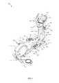
- FIG. 1depicts an example of an exercise machine 100 .
- the exercise machine 100includes a frame 102 attached to a base 104 .
- the frame 102includes a post 108 .
- a console 110is connected to the post 108 .
- the base 104has a first support beam 112 and a second support beam 114 .
- the base 104is connected to a housing 116 which contains a flywheel (not shown) or another type of resistance mechanism.
- the flywheelis connected to a first crank assembly 118 and a second crank assembly (not shown).
- the first crank assembly 118is connected to a first pedal assembly 120 and the second crank assembly is connected to a second pedal assembly 122 .
- the first crank assembly 118includes a first crank wheel 124 connected to the first pedal assembly 120 via a first pivot joint 126 .
- the first crank wheel 124may be integrated into the housing 116 .
- the second crank wheelis connected to the second pedal assembly 122 via a second pivot joint 128 .
- the second crank wheelmay be integrated into the housing 116 similar to the first crank wheel 124 .
- Each of the first pedal assembly 120 and the second pedal assembly 122includes a pedal beam 130 , and a pedal 132 connected to the pedal beam 130 .
- the pedal 132may include a gripping surface 134 to grip a user's shoe as a user executes an exercise with the exercise machine 100 .
- the pedal 132may be bolted or otherwise fastened to the pedal beam 130 .
- a first connecting beam 136is attached to the pedal beam 130 at a first connection joint 138 .
- the first connecting beam 136is connected a first arm assembly 140 at a first joint 142 .
- the first arm assembly 140connects to the frame 102 at a first pivot connection 144 .
- the first pivot connection 144is also attached to a first handle section 146 which is accessible to the user as the user is performing an exercise with the exercise machine 100 .
- the pedal beam 130 of the second pedal assembly 122is connected to second connecting beam (not shown) at a second connection joint (not shown).
- the second connecting beamis connected to a second arm assembly 148 at a second joint 150 .
- the second arm assembly 148connects to the frame 102 at a second pivot connection 152 .
- the second pivot connection 152is also attached to a second handle section 154 which is also accessible to the user as the user is performing an exercise with the exercise machine 100 .
- the first pivot connection 144 and second pivot connection 152connect the first and second arm assemblies 140 , 148 to a pivot rod 160 connected to the frame 102 .
- a bushing 164is located on the pivot rod 160 between the console 110 and the pivot connections 144 , 152 .
- the bushing 164may be incorporated into the exercise machine in any appropriate joint.
- a non-limiting list of joints where the bushing may be incorporated into an exercise machineincludes joint 126 , joint 128 , joint 138 , joint 142 , joint 150 , other joints, and combinations thereof.
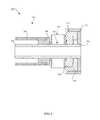
- FIG. 2is a cross-sectional view of the pivot rod assembly 200 along line A.
- the bushing 164is mounted on the pivot arm 162 .
- the frame 102provides a cavity to accept the pivot arm 162 .
- the bushing 164may be located between the first pivot connection 144 and the frame 102 .
- the first pivot connection 144includes a sleeve 204 and a pivot spacer 206 .
- the frame 102includes a first spacer 208 and a second spacer 210 .
- the sleeve 204 and the pivot spacer 206push the bushing 164 into the first spacer 208 and the second spacer 210 which are pushed into the frame 102 .
- the bushing 164has an interference fit 212 between the bushing 164 and the first spacer 208 .
- the bushing 614may be a loose fit, line on line fit, or a tight fit between a thru-hole 202 of the bushing 164 and an outer diameter of the pivot arm 162 .
- a diameter of the thru-hole 202 of the bushing 164is larger than the outer diameter of the pivot arm 163 .
- the diameter of the thru-hole 202is the same as the outer diameter of the pivot arm 163 .
- the diameter of the thru-hole 202is smaller than the outer diameter of the pivot arm 163 .
- a single pivot arm 162attaches to the frame 102 and has a symmetrical assembly on the other side of the frame 102 to attach a second pivot connection.
- the frame 102may comprise two pivot arms which may separately connect the frame 102 and their respective pivot connection.
- FIG. 3shows an isometric view of an exemplary bushing 164 .
- the bushing 164includes three parts: a circular body 300 , a first circular plate 302 , and a second circular plate 304 .
- the first circular plate 302 and second circular plate 304are connected to the circular body.
- the first circular plate 302is connected to a first side of the circular body 300 and the second circular plate 304 is connected to a second side of the circular body 300 .
- the first circular plate 302 , circular body 300 , and the second circular plate 304have a common outer diameter.
- the bushing 164has a common thru-hole 400 through the first circular plate 302 , circular body 300 , and the second circular plate 304 .
- the thru-hole 400is in substantially the center of the bushing 164 .
- the first and second circular plates 302 , 304may be symmetrical and/or identical.
- the first and second circular platesinclude a lip 402 and a fillet 404 between the lip and the flat portion 406 of the circular plate 302 , 304 .
- the lip 402is proximate the thru-hole 400 and extends beyond a thickness t of the circular plate 302 , 304 .
- the fillet 404rounds the interior corner between the flat portion 406 and the lip 402 .
- FIG. 5shows an exemplary side view of the bushing 164 .
- the first circular plate 302is depicted in the figure.
- the second circular plate 304is identical to the first plate 302 .
- the side viewshows the thru-hole 400 , lip 402 , and outer diameter 500 of the bushing 164 .
- the side viewalso shows a variety of apertures 502 in the first circular plate 302 .
- the first series of apertures 502are circular and form a pattern around the flat portion 406 of the circular plate 302 .
- the apertures 502are grouped into a series of three apertures 502 and are evenly spaced about a second series of apertures 504 .
- a total of three apertures 504are square-shaped and evenly distributed about the flat portion 406 of the circular plate 302 .
- the groups of the first series of aperturesare spaced in between the series of second apertures 504 .
- Both the first and second series of apertures 502 , 504are located far enough away from the lip to avoid contacting the fillet 404 between the lip 402 and the flat portion 406 .
- the apertures 502 , 504are also located far enough away from the outer diameter 500 to define a complete void in the flat portion.
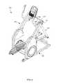
- FIG. 6is another example of an exercise machine 600 that may incorporate the bushing 164 .
- the exercise machine 600includes a frame 602 with a base 604 .
- the frame 602has a first arm assembly 606 and a second arm assembly 608 connected to it.
- the first arm assembly 606is connected to a first pivot arm 610 which is connected to the frame 602 .
- the bushing 164is located between the arm assembly 608 and the frame 102 .
- the second arm assembly 608is connected to a second pivot arm (not shown) which is connected to the frame 602 .
- the bushing 164may be incorporated into any of the appropriate joints depicted in the exercise machine 600 .
- FIG. 7is another example of an exercise machine 700 that may incorporate the bushing 164 .
- the exercise machine 700includes a frame 702 with a base 704 .
- the frame 702has a first arm assembly 706 and a second arm assembly 710 connected to it.
- the first arm assemblyis 706 connected to a pivot arm 712 on a first side 714 of the frame 702 .
- the bushing 164is located between the first arm assembly 706 and the frame 702 .
- the second arm assembly 710is connected to the pivot arm (not shown) on a second side 716 of the frame 702 .
- the bushing 164may be incorporated into any of the appropriate joints depicted in the exercise machine 700 .
- a console 716is attached to the frame 702 .
- the console 716may contain a display and controls.
- the controlsmay allow the user to specify a resistance level to be applied by the resistance mechanism.
- the controlsmay also be used to control other operating parameters of the exercise machine, such as incline, side to side tilt, resistance, speaker volume, programmed exercise routines, other parameters, or combinations thereof.
- the displaymay show selected parameters to the user. Additionally, the display may be capable of presenting the user's physiological parameters, timers, clocks, scenery, routes, other types of information, or combinations thereof.
- FIG. 8is another example of an exercise machine 800 that may incorporate the bushing 164 .
- the exercise machine 800includes a frame 802 with a base 804 .
- the frame 802has a first arm assembly 806 and a second arm assembly 810 connected to it.
- the first arm assembly 806is connected to a pivot arm 812 on a first side 814 of the frame 802 .
- the bushing 164is located between the first arm assembly 806 and the frame 802 .
- the second arm assembly 810is connected to the pivot arm (not shown) on a second side 816 of the frame 802 .
- the bushing 164may be incorporated into any of the appropriate joints depicted in the exercise machine 800 .
- the systems and methods disclosed hereinmay provide a user with an exercise machine with a bushing that has long life, that reduces and/or eliminates noise, and that reduces and/or eliminates vibrations in the exercise machine joints.
- the bushings described hereinmay replace previous wave washers used in certain joints in exercise machines. These wave washers typically experienced a 30,000 rotation life cycle before they failed. The wave washers also produced a noise and generated vibrations during those 30,000 rotations.
- the bushings described in the present disclosurehave exhibited a 500,000 or more rotation life cycle. Additionally, the bushing described in the present disclosure has reduced and/or eliminated noise and vibrations at the joints.
- the bushingmay be disposed around a pivot rod.
- a first component of the joint and a second component of the jointmay also be positioned about the pivot rod with the bushing between the first component and the second component.
- the bushingmay be held in compression between the first component and the second component.
- the first componentmay be any appropriate component of the exercise machine.
- the first componentmay be a portion of the frame, an arm assembly, a beam, a portion of a rotary resistance mechanism, a base, an upright structure, a foot pedal beam, another type of component, or combinations thereof.
- the first componentis rotationally fixed with respect to the pivot rod. In other examples, the first component is rotationally disposed about the pivot rod.
- the second componentmay be any appropriate component of the exercise machine.
- the first componentmay be a portion of the frame, an arm assembly, a beam, a portion of a rotary resistance mechanism, a base, an upright structure, a foot pedal beam, another type of component, or combinations thereof.
- the second componentis rotationally fixed with respect to the pivot rod. In other examples, the second component is rotationally disposed about the pivot rod.
- the bushingmay be located at any appropriate joint of the exercise machine.
- the bushingmay be located in a joint between the frame and an arm assembly, in a joint between an arm assembly and a beam to the foot pedal, in a joint between a beam and rotary resistance mechanism, in a joint between a rotary resistance mechanism and an arm assembly, in a joint between a first beam and a second beam, in a joint between a beam and a crank arm, in a joint between a crank arm and an arm assembly, in another type of joint, or combinations thereof.
- the beamis a linkage that connects moving parts of the exercise machine. In some circumstances, these linkages move with the moving parts during the performance of an exercise.
- Bushing materialis compressed between different components of the joints. This compressive arrangement prevents the bushing from vibrating at the joint, which also reduces the wear and tear on the joint. Thus, a continuous compressive force on the bushing described herein preserves the life the bushing.
- the elastic materialis sandwiched between circular plates made of a material that is stiffer than the elastic material. The compressive loads from the joint's components are first applied to these stiffer plates. The loads are substantially evenly distributed across the plates' areas so that there is little to no peak loading in the elastic material. With the compressive loads substantially equally distributed throughout the elastic material, the useful life of the elastic materials significantly increases.
- the constant compressive loadalso pre-stresses the elastic material, restricting the distance that the elastic material can stretch during the cycles. As a result, the elastic material experiences less fatigue, creep, and other types of mechanical failures associated with a high volume of cycles.
- the loadis applied to the first side of the bushing through the first plate and to the second plate which is on the opposite side of the bushing from the first plate. In some examples, side loads that are less than 25 pounds have not produced the life increase benefits described herein. Further, side loads that are over 75 pounds have also demonstrated a shorter life span.
- the precompressive side loadis between 25 and 75 pounds. In another example, the precompressive side loads is 30 to 60 pounds. In yet another example, the precompressive side load is between 35 and 55 pounds.
- the precompressive side loadis between 40 and 50 pounds.
- the elastic materialhas the characteristic of compressing by 0.5 to 2.5 millimeters when the precompressive side load is applied.
- the elastic materialhas the characteristic of compressing by 1.0 to 2.5 millimeters when the precompressive side load is applied.
- the elastic materialhas the characteristic of compressing by 1.5 to 2.0 millimeters when the precompressive side load is applied.
- an elastic material that is precompressed by 1.5 millimeters under a load of 40 to 55 poundsimproves the life cycle of the bushing from 30,000 cycles to 500,000 cycles of useful life.
- the precompressive loadis a baseline load applied to the side of the bushing.
- the side loads applied to the bushingincrease above the baseline load and decrease under the base line load.
- the bushing's widthis shorten, and when the loads decrease, the bushing's width increase. Since the bushing is already under a precompressive load prior to the cycle, the bushing may still be under some compressive load even when the side loads are at a lowest level during the cycle. With the bushing under a compressive load at the lowest point in the cycle, the bushing remains fixed in place. With the joint components and the bushing remaining in contact throughout the entire cycle, no gaps are formed in the joint and a reduction in vibration and noise is achieved.
- the elastic material's volumecompresses at a diminishing rate as the side loads increase. For example, as the elastic material is subjected to a compressive force, the elastic material's molecules are moved closer together. But, as the molecules are brought closer together, the force required to move the molecules even closer together increases. Thus, under the precompressive load, the bushing is much more resistant to compression than the bushing would be when no precompressive load is applied. As a result, the precompression not only prevents the bushing from moving during the cycle, but the precompression actual reduces and/or eliminates the fluctuating widths of the bushing, which reduces and/or eliminates vibrations and noise associated with bushings during the cycles.
- the exercise machinemay include a frame and a resistance mechanism attached to the frame.
- a crank assemblymay be in mechanical communication with the resistance mechanism.
- the crank assemblyincludes a crank arm and a roller connected to the crank arm.
- the exercise machinealso includes a pedal assembly movably attached to the crank assembly and movable in the performance of an exercise.
- the pedal assemblymay include a pedal beam with a foot support attached to the pedal beam.
- the pedal assemblymay be pivotally attached to an arm assembly.
- the arm assemblymay be moveably attached to an upper portion of the frame of the exercise machine.
- the arm assemblyincludes an arm support, a handle, and a pivot connection.
- the pivot connectionallows the arm assembly to pivot with respect to the upper portion of the frame of the exercise machine.
- the pivot connectionattaches to a pivot rod which may be attached to the frame.
- two arm assembliesmay be connected to a single pivot rod.
- each arm assemblymay connect to a respective pivot rod.
- the pivot armsmay connect to two different portions of the frame.
- the frameis a single column extending upward from the base
- the pivot armmay pass through an accepting feature in the single column frame.
- the single column framemay accept two pivot arms to prevent motion from being transferred from one arm assembly to another.
- the usermay grip the handle in the arm assembly.
- the user's handfollows the arm supports instead of driving their movement, or if the user's arms drive the arm supports movement, the loads imposed on the arm supports from the user are primarily fore/aft forces.
- the loads imposed on the arm supports from the userare primarily fore/aft forces.
- the userdoes not generally impose a significant force.
- vibrations in the arm supportsare less restricted in these directions.
- the weight of the useris loaded to the joint which tends to suppress vibrations.
- the movement in the arm supportsmay be more prone to vibrations than joints that carry a significant portion of the user's weight. Consequently, the forces that affect the joints are different depending on whether the joint is a load bearing joint or not.
- the arm assemblymay have a tendency to vibrate due to external forces on the arm assembly and not forces induced by the user.
- the vibrationsmay be side to side vibrations, a lateral movement in the arm assembly from the direction of the pivot connection.
- the usermay, in some instances, experience oscillating vibrations in the arm assemblies.
- the vibrationsmay have one or more sources and may not be desirable in a user experience or to the exercise machine.
- the bushings described aboveare specifically constructed for these levels of vibrations. The principles described herein can be applied to the joints included in the pedal assembly, but some modifications may be made to account for the load bearing nature of the joints in the pedal assembly.
- the vibrationsmay be caused by external factors to the exercise machine.
- the floor, on which the exercise machine restsmay not be completely level which may result in vibrations being transmitted through the assembly of the exercise machine.
- a nearby exercise machinesuch as in a gym or other fitness setting, may transmit vibrations into the floor which may transfer into the exercise machine and travel through its structure.
- the usermay be running which may cause surrounding exercise machines to reverberate the motions as it is transferred through a common floor surface.
- Vibrationsmay additionally be caused by sources internal to the exercise machine. Tolerance differentials in different components of the assembly of the exercise machine may cause oscillations or side to side movement of the arm assembly. Additionally, the user may enact forces on the exercise machine when utilizing the machine. The amount of energy transmitted from the user into the exercise machine may depend on height and weight of the user, speed of use, overall grace of the user, and the like. The forces on the exercise machine may transmit to the handles through the foot support connection to the arm assembly. Similarly, the foot support connection to the flywheel may cause vibration-related forces to be transmitted to the frame which may radiate to the arm assemblies. Also, a combination of both may cause arm assembly vibrations.
- the side to side play of the arm assemblymay be lateral to the pivot motion of the arm assembly.
- One cause of side to side playmay be a tolerance differential as the exercise machine is assembled. When parts are manufactured, the parts have a variation in final sizing usually called a tolerance. Tolerance allowances vary depending on manufacturing capabilities, cost of manufacturing, desired component tolerances, and the like.
- the arm assemblyis part of a loop including the pivot arm, base frame, fly wheel, crank assembly, and foot support. As all of the tolerances of the components in this loop are calculated, the accumulated tolerances may result in the arm assembly not being truly centered for optimal performance. Rather the final mounted location of the arm assembly may be subject to the tolerances of the components.
- the arm assemblymay sway, or move, from side to side.
- the amount of swaymay depend on the actual tolerance variance present in the final assembled exercise machine.
- the side to side playmay range from minimal/unnoticeable by the user to the arm assembly noticeably swaying from side to side.
- a component in the assemblymay reduce noise and vibrations, and, in some instances, reduce side to side sway that may be present in the arm assembly.
- the reduction in noise and vibrationsmay be specific to the arm assembly and may result in a lack of transferring vibrations to components in the arm assembly or may result in absorbing vibration energies in the arm assembly and preventing the arm assembly from resonating due to vibrations.
- a bushingmay work to reduce vibrations and reduce tolerance factors in the swaying of the arm assembly.
- the bushingmay comprise an assembly of a circular body with two circular plates connected to each side of the circular body.
- the circular body of the bushingmay comprise an elastic, flexible material.
- the materialmay be polyurethane, foam, flexible polyvinyl chloride (PVC), rubber, thermoplastic elastomer, thermoplastic rubber, and the like.
- the materialmay exhibit a hardness characteristic between Shore 30 A and Shore 50 A. This range on the durometer scale may provide an extra soft to soft hardness according to a durometer reading.
- the relative softness of the materialmay increase the flexibility and compressibility of the material.
- the materialmay have sufficient relative hardness to provide counter active forces to prevent the bushing from collapsing under increased pressure or strain.
- the durometer readingmay additionally reflect a level of elasticity of the material in its ability to conform to shapes and maintain a solid form when not installed in a usage case.
- the elasticitymay provide for manufacturing repeatability.
- the materialmay exhibit a hardness characteristic of Shore 40 A.
- a Shore Hardness scalemay be used for measuring the hardness of different materials.
- a Shore Hardness gaugemay outwardly resemble a tire gauge.
- the Shore Hardness gaugemay include a needle on a spring protruding from one end. To measure the hardness, the needle is placed against the material and pressure is applied. Once the gauge is firmly pressed against the material and the needle has reached a maximum penetration, the measurement needle indicates the corresponding hardness measurement.
- the circular platesmay be a rigid material and may include acetal, steel, aluminum, acrylonitrile butadiene styrene, rigid PVC, nylon, and the like. While this example has been described with reference to a circular body and/or circular plates, the shapes of the body and plates may be any appropriate geometry.
- the plates and/or the bodymay include a generally square geometry, a generally triangular geometry, a generally elliptical geometry, a generally polygonal geometry, an asymmetric geometry, or combinations thereof.
- the bushingmay be located on the pivot arm between the arm assembly and the frame.
- the arm assemblymay include a pivot connection which may pivotally connect the arm assembly to the pivot rod and frame.
- the pivot connectionmay include components which mate to the bushing including flat washers, spacers, and the like that may comprise multiple materials.
- the bushingmay mate with one of these components. Additionally, the bushing may mate on an opposing side with a portion of the frame or with one or more components which may interface between the frame and the bushing.
- the bushingmay comprise one or more apertures in the two circular plates.
- the aperturesmay align the bushing to the frame and/or the pivot rod.
- multiple apertures in the two circular platesmay additionally provide compression relief to the circular body as the bushing is compressed between the arm assembly and the frame as described below. Alternatively, the apertures may change the compression and torsional properties of the bushing, while eliminating weight.
- the arm assemblyWhen the arm assembly is mounted on the pivot arm, the arm assembly may compress the bushing between the frame and arm assembly.
- the bushingmay compress due to the circular body being an elastic, flexible material.
- the two circular platesmay aid in the compression of the bushing.
- the compressing of the bushingmay cause an interference fit between the bushing and the frame or components there between, the bushing and the arm assembly, or both.
- the compressionmay ensure the bushing is flush against the arm assembly. Due to the flushness of the contact between the arm assembly and the bushing, any vibrations oscillating in the frame may be absorbed by the elastic, flexible material of the bushing and may not transfer to the arm assembly.
- the two circular platesmay ensure the compression is uniform on the flexible material of the body of the bushing.
- the bushingmay act as a damper on the arm assembly and absorb vibration energy transmitted into the arm assembly. The bushing may absorb the vibration and attenuate the vibrations into the exercise machine and/or into the arm assembly.
- the compressibility of the bushingmay also allow for any tolerance gaps that present themselves when assembling the exercise machine. As mentioned above, all components have tolerances which may present themselves at assembly in undesirable outcomes, such as noticeable side to side movement of the arm assembly.
- the elasticity and flexibility of the bushingmay allow the arm assembly to be mounted on the pivot arm and compress the bushing. The bushing may vitiate, or reduce, any effects tolerance gaps have on the centering of the arm assembly. Instead, the bushing may allow the arm assembly to be aligned properly with respect to the pedal assembly and the pivot arm.
- a single bushingmay be used between the arm support and the frame. In other embodiments, multiple bushings may be used between the arm support and the frame.
- the bushingsmay be mounted consecutively or may be separated by a spacer or washer.
- the bushingsmay additionally vary in thickness of the circular body and the circular plates to customize for different types of exercise machines and uses.
- the bushingis a single component assembly which may be installed as such onto the exercise machine.
- a single component assemblymay reduce complexity in part count of the exercise machine, reduce overhead in ordering hardware for the exercise machine, and reduce general complexity of tracking the component.
- the bushingmay be installed in three separate pieces and still serve the same functionality. For example, a first circular plate may be installed, followed by the circular body, and then the second circular plate. While the integrated assembly of the bushing may aid in reduction of parts and installation as mentioned, each piece of the bushing may have its own functionality and purpose.
- the platesprovide a stable and structured surface for the flexible body to align against and with. The plates may also provide a consistent interface between the flexible body and interfacing components.
- the flexible bodymay conform to surface irregularities on interfacing components and may not provide a steady and consistent pressure between the two parts contacting interface.
- the rigid plate located between an interfacing component and the flexible bodyprovides a consistent surface for mutual compression between the components.
- installing the plates with the flexible bodymay not achieve the affects described herein.
- the platesmay not be flexible enough to allow for vibration control, potential part tolerance issues, and the like.
- the exercise machinemay incorporate a single bushing, two bushings, more than two bushings, an even number of bushings, an odd number of bushings, or combinations thereof.
Landscapes
- Health & Medical Sciences (AREA)
- Physical Education & Sports Medicine (AREA)
- General Health & Medical Sciences (AREA)
- Cardiology (AREA)
- Engineering & Computer Science (AREA)
- Vascular Medicine (AREA)
- Orthopedic Medicine & Surgery (AREA)
- Biophysics (AREA)
- Life Sciences & Earth Sciences (AREA)
- General Engineering & Computer Science (AREA)
- Mechanical Engineering (AREA)
- Aviation & Aerospace Engineering (AREA)
- Physics & Mathematics (AREA)
- Acoustics & Sound (AREA)
- Rehabilitation Tools (AREA)
- Pivots And Pivotal Connections (AREA)
- Vibration Prevention Devices (AREA)
Abstract
Description
Claims (20)
Priority Applications (1)
| Application Number | Priority Date | Filing Date | Title |
|---|---|---|---|
| US15/248,732US9968821B2 (en) | 2015-08-28 | 2016-08-26 | Bushing in an exercise machine |
Applications Claiming Priority (2)
| Application Number | Priority Date | Filing Date | Title |
|---|---|---|---|
| US201562211226P | 2015-08-28 | 2015-08-28 | |
| US15/248,732US9968821B2 (en) | 2015-08-28 | 2016-08-26 | Bushing in an exercise machine |
Publications (2)
| Publication Number | Publication Date |
|---|---|
| US20170056706A1 US20170056706A1 (en) | 2017-03-02 |
| US9968821B2true US9968821B2 (en) | 2018-05-15 |
Family
ID=58097437
Family Applications (1)
| Application Number | Title | Priority Date | Filing Date |
|---|---|---|---|
| US15/248,732Active2037-01-24US9968821B2 (en) | 2015-08-28 | 2016-08-26 | Bushing in an exercise machine |
Country Status (4)
| Country | Link |
|---|---|
| US (1) | US9968821B2 (en) |
| CN (1) | CN107921308B (en) |
| TW (1) | TWI603757B (en) |
| WO (1) | WO2017040300A1 (en) |
Cited By (53)
| Publication number | Priority date | Publication date | Assignee | Title |
|---|---|---|---|---|
| US10188890B2 (en) | 2013-12-26 | 2019-01-29 | Icon Health & Fitness, Inc. | Magnetic resistance mechanism in a cable machine |
| US10252109B2 (en) | 2016-05-13 | 2019-04-09 | Icon Health & Fitness, Inc. | Weight platform treadmill |
| US10258828B2 (en) | 2015-01-16 | 2019-04-16 | Icon Health & Fitness, Inc. | Controls for an exercise device |
| US10272317B2 (en) | 2016-03-18 | 2019-04-30 | Icon Health & Fitness, Inc. | Lighted pace feature in a treadmill |
| US10279212B2 (en) | 2013-03-14 | 2019-05-07 | Icon Health & Fitness, Inc. | Strength training apparatus with flywheel and related methods |
| US10293211B2 (en) | 2016-03-18 | 2019-05-21 | Icon Health & Fitness, Inc. | Coordinated weight selection |
| US10343017B2 (en) | 2016-11-01 | 2019-07-09 | Icon Health & Fitness, Inc. | Distance sensor for console positioning |
| US10376736B2 (en) | 2016-10-12 | 2019-08-13 | Icon Health & Fitness, Inc. | Cooling an exercise device during a dive motor runway condition |
| US10426989B2 (en) | 2014-06-09 | 2019-10-01 | Icon Health & Fitness, Inc. | Cable system incorporated into a treadmill |
| US10433612B2 (en) | 2014-03-10 | 2019-10-08 | Icon Health & Fitness, Inc. | Pressure sensor to quantify work |
| US10441844B2 (en) | 2016-07-01 | 2019-10-15 | Icon Health & Fitness, Inc. | Cooling systems and methods for exercise equipment |
| US10441840B2 (en) | 2016-03-18 | 2019-10-15 | Icon Health & Fitness, Inc. | Collapsible strength exercise machine |
| US10449416B2 (en) | 2015-08-26 | 2019-10-22 | Icon Health & Fitness, Inc. | Strength exercise mechanisms |
| US10471299B2 (en) | 2016-07-01 | 2019-11-12 | Icon Health & Fitness, Inc. | Systems and methods for cooling internal exercise equipment components |
| US10493349B2 (en) | 2016-03-18 | 2019-12-03 | Icon Health & Fitness, Inc. | Display on exercise device |
| US10500473B2 (en) | 2016-10-10 | 2019-12-10 | Icon Health & Fitness, Inc. | Console positioning |
| US10543395B2 (en) | 2016-12-05 | 2020-01-28 | Icon Health & Fitness, Inc. | Offsetting treadmill deck weight during operation |
| US10561894B2 (en) | 2016-03-18 | 2020-02-18 | Icon Health & Fitness, Inc. | Treadmill with removable supports |
| US10625114B2 (en) | 2016-11-01 | 2020-04-21 | Icon Health & Fitness, Inc. | Elliptical and stationary bicycle apparatus including row functionality |
| US10625137B2 (en) | 2016-03-18 | 2020-04-21 | Icon Health & Fitness, Inc. | Coordinated displays in an exercise device |
| US10661114B2 (en) | 2016-11-01 | 2020-05-26 | Icon Health & Fitness, Inc. | Body weight lift mechanism on treadmill |
| US10729965B2 (en) | 2017-12-22 | 2020-08-04 | Icon Health & Fitness, Inc. | Audible belt guide in a treadmill |
| US10786706B2 (en) | 2018-07-13 | 2020-09-29 | Icon Health & Fitness, Inc. | Cycling shoe power sensors |
| US10918905B2 (en) | 2016-10-12 | 2021-02-16 | Icon Health & Fitness, Inc. | Systems and methods for reducing runaway resistance on an exercise device |
| US10940360B2 (en) | 2015-08-26 | 2021-03-09 | Icon Health & Fitness, Inc. | Strength exercise mechanisms |
| US10953305B2 (en) | 2015-08-26 | 2021-03-23 | Icon Health & Fitness, Inc. | Strength exercise mechanisms |
| US11000730B2 (en) | 2018-03-16 | 2021-05-11 | Icon Health & Fitness, Inc. | Elliptical exercise machine |
| US11033777B1 (en) | 2019-02-12 | 2021-06-15 | Icon Health & Fitness, Inc. | Stationary exercise machine |
| US11058913B2 (en) | 2017-12-22 | 2021-07-13 | Icon Health & Fitness, Inc. | Inclinable exercise machine |
| US11058914B2 (en) | 2016-07-01 | 2021-07-13 | Icon Health & Fitness, Inc. | Cooling methods for exercise equipment |
| US11187285B2 (en) | 2017-12-09 | 2021-11-30 | Icon Health & Fitness, Inc. | Systems and methods for selectively rotationally fixing a pedaled drivetrain |
| US11298577B2 (en) | 2019-02-11 | 2022-04-12 | Ifit Inc. | Cable and power rack exercise machine |
| US11326673B2 (en) | 2018-06-11 | 2022-05-10 | Ifit Inc. | Increased durability linear actuator |
| US11451108B2 (en) | 2017-08-16 | 2022-09-20 | Ifit Inc. | Systems and methods for axial impact resistance in electric motors |
| US11534651B2 (en) | 2019-08-15 | 2022-12-27 | Ifit Inc. | Adjustable dumbbell system |
| US11534654B2 (en) | 2019-01-25 | 2022-12-27 | Ifit Inc. | Systems and methods for an interactive pedaled exercise device |
| US11673036B2 (en) | 2019-11-12 | 2023-06-13 | Ifit Inc. | Exercise storage system |
| US11794070B2 (en) | 2019-05-23 | 2023-10-24 | Ifit Inc. | Systems and methods for cooling an exercise device |
| US11850497B2 (en) | 2019-10-11 | 2023-12-26 | Ifit Inc. | Modular exercise device |
| US11878199B2 (en) | 2021-02-16 | 2024-01-23 | Ifit Inc. | Safety mechanism for an adjustable dumbbell |
| US11931621B2 (en) | 2020-03-18 | 2024-03-19 | Ifit Inc. | Systems and methods for treadmill drift avoidance |
| US11951377B2 (en) | 2020-03-24 | 2024-04-09 | Ifit Inc. | Leaderboard with irregularity flags in an exercise machine system |
| US12029961B2 (en) | 2020-03-24 | 2024-07-09 | Ifit Inc. | Flagging irregularities in user performance in an exercise machine system |
| US12029935B2 (en) | 2021-08-19 | 2024-07-09 | Ifit Inc. | Adjustment mechanism for an adjustable kettlebell |
| US20240288030A1 (en)* | 2023-02-27 | 2024-08-29 | Life Fitness, Llc | Pivot devices for exercise equipment |
| US12176009B2 (en) | 2021-12-30 | 2024-12-24 | Ifit Inc. | Systems and methods for synchronizing workout equipment with video files |
| US12219201B2 (en) | 2021-08-05 | 2025-02-04 | Ifit Inc. | Synchronizing video workout programs across multiple devices |
| US12263371B2 (en) | 2021-04-27 | 2025-04-01 | Ifit Inc. | Devices, systems, and methods for rotating a tread belt in two directions |
| US12280294B2 (en) | 2021-10-15 | 2025-04-22 | Ifit Inc. | Magnetic clutch for a pedaled drivetrain |
| US12350573B2 (en) | 2021-04-27 | 2025-07-08 | Ifit Inc. | Systems and methods for cross-training on exercise devices |
| US12350547B2 (en) | 2022-02-28 | 2025-07-08 | Ifit Inc. | Devices, systems, and methods for moving a movable step through a transition zone |
| US12409375B2 (en) | 2022-03-18 | 2025-09-09 | Ifit Inc. | Systems and methods for haptic simulation in incline exercise devices |
| US12433815B2 (en) | 2020-10-02 | 2025-10-07 | Ifit Inc. | Massage roller with pressure sensors |
Families Citing this family (3)
| Publication number | Priority date | Publication date | Assignee | Title |
|---|---|---|---|---|
| CN107921308B (en)* | 2015-08-28 | 2020-04-10 | 爱康保健健身有限公司 | Sleeve in body-building apparatus |
| WO2018128891A1 (en)* | 2017-01-03 | 2018-07-12 | Engen Fitness, Inc. | Guided movement exercise machine |
| TWI733281B (en)* | 2019-12-19 | 2021-07-11 | 謝金龍 | Rowing exercise machine or pedaling device for rowing boat |
Citations (14)
| Publication number | Priority date | Publication date | Assignee | Title |
|---|---|---|---|---|
| US3738661A (en)* | 1971-11-22 | 1973-06-12 | B Moller | Golf exercising device |
| US4830362A (en) | 1988-04-13 | 1989-05-16 | Bull John W | Full body, shock-free aerobic and anaerobic exercising machine for use in the standing position |
| US5139469A (en) | 1990-08-02 | 1992-08-18 | Zurn Industries, Inc. | Exercise machine and transmission therefor |
| US5244444A (en)* | 1992-09-30 | 1993-09-14 | Frank Wostry | Exerciser |
| US5695434A (en) | 1995-02-01 | 1997-12-09 | Icon Health & Fitness, Inc. | Riding-type exercise machine |
| US6835166B1 (en) | 2003-08-01 | 2004-12-28 | Kenneth W. Stearns | Exercise apparatus with elliptical foot motion |
| TWM322829U (en) | 2007-03-30 | 2007-12-01 | Rau-Shing Tsai | Swinging exerciser |
| US7749137B2 (en)* | 2006-11-16 | 2010-07-06 | Nautilus, Inc. | Variable stride exercise device |
| US7775947B2 (en)* | 2006-08-02 | 2010-08-17 | Powerblock Holdings, Inc. | Selectorized dumbbell having shock absorbing system and weight plates with an elastomer encasement |
| US8167734B2 (en)* | 2009-07-09 | 2012-05-01 | Alexander Boldin | Golf swing training device |
| TWM458484U (en) | 2013-04-03 | 2013-08-01 | jin-shun Li | Hook structure |
| TWM465941U (en) | 2013-02-08 | 2013-11-21 | Chen Yu Ting | Limbs rehabilitation device |
| US20140135180A1 (en) | 2012-10-31 | 2014-05-15 | Icon Health & Fitness, Inc. | Exercise Devices Having Damped Joints and Related Methods |
| US20170056706A1 (en)* | 2015-08-28 | 2017-03-02 | Icon Health & Fitness, Inc. | Bushing in an Exercise Machine |
Family Cites Families (6)
| Publication number | Priority date | Publication date | Assignee | Title |
|---|---|---|---|---|
| CN2559371Y (en)* | 2002-07-16 | 2003-07-09 | 乔山健康科技股份有限公司 | Elliptical exercise machine with adjustable stroke |
| CN2865779Y (en)* | 2006-01-27 | 2007-02-07 | 旭凯国际股份有限公司 | fully collapsible stepper |
| TWM380146U (en)* | 2009-11-12 | 2010-05-11 | Iviva Internat Corp | Oval stroll machine capable of adjusting span |
| CN201840827U (en)* | 2010-06-18 | 2011-05-25 | 赖膺州 | Elliptical Machine Construction |
| TWM454848U (en)* | 2012-07-02 | 2013-06-11 | Icon Ip Inc | Adjustable resistance based exercise apparatus |
| CN202777597U (en)* | 2012-07-27 | 2013-03-13 | 朗美(厦门)健身器材有限公司 | Elliptical machine |
- 2016
- 2016-08-26CNCN201680044641.4Apatent/CN107921308B/enactiveActive
- 2016-08-26USUS15/248,732patent/US9968821B2/enactiveActive
- 2016-08-26WOPCT/US2016/049029patent/WO2017040300A1/ennot_activeCeased
- 2016-08-29TWTW105127656Apatent/TWI603757B/enactive
Patent Citations (14)
| Publication number | Priority date | Publication date | Assignee | Title |
|---|---|---|---|---|
| US3738661A (en)* | 1971-11-22 | 1973-06-12 | B Moller | Golf exercising device |
| US4830362A (en) | 1988-04-13 | 1989-05-16 | Bull John W | Full body, shock-free aerobic and anaerobic exercising machine for use in the standing position |
| US5139469A (en) | 1990-08-02 | 1992-08-18 | Zurn Industries, Inc. | Exercise machine and transmission therefor |
| US5244444A (en)* | 1992-09-30 | 1993-09-14 | Frank Wostry | Exerciser |
| US5695434A (en) | 1995-02-01 | 1997-12-09 | Icon Health & Fitness, Inc. | Riding-type exercise machine |
| US6835166B1 (en) | 2003-08-01 | 2004-12-28 | Kenneth W. Stearns | Exercise apparatus with elliptical foot motion |
| US7775947B2 (en)* | 2006-08-02 | 2010-08-17 | Powerblock Holdings, Inc. | Selectorized dumbbell having shock absorbing system and weight plates with an elastomer encasement |
| US7749137B2 (en)* | 2006-11-16 | 2010-07-06 | Nautilus, Inc. | Variable stride exercise device |
| TWM322829U (en) | 2007-03-30 | 2007-12-01 | Rau-Shing Tsai | Swinging exerciser |
| US8167734B2 (en)* | 2009-07-09 | 2012-05-01 | Alexander Boldin | Golf swing training device |
| US20140135180A1 (en) | 2012-10-31 | 2014-05-15 | Icon Health & Fitness, Inc. | Exercise Devices Having Damped Joints and Related Methods |
| TWM465941U (en) | 2013-02-08 | 2013-11-21 | Chen Yu Ting | Limbs rehabilitation device |
| TWM458484U (en) | 2013-04-03 | 2013-08-01 | jin-shun Li | Hook structure |
| US20170056706A1 (en)* | 2015-08-28 | 2017-03-02 | Icon Health & Fitness, Inc. | Bushing in an Exercise Machine |
Non-Patent Citations (6)
| Title |
|---|
| English Translation of Taiwan First Office Action and Search Report issued for 105127656 dated Feb. 17, 2017. |
| English Translation via Orbit.com of the Abstract of TW 337201. Jul. 21, 1998. |
| English Translation via Orbit.com of the Abstract of TW M322829. Dec. 1, 2007. |
| English Translation via Orbit.com of the Abstract of TW M454848. Jun. 11, 2013. |
| English Translation via Orbit.com of the Abstract of TW M465941. Nov. 21, 2013. |
| International Search Report issued for PCT/US2016/049029 dated Nov. 18, 2016. |
Cited By (81)
| Publication number | Priority date | Publication date | Assignee | Title |
|---|---|---|---|---|
| US11878206B2 (en) | 2013-03-14 | 2024-01-23 | Ifit Inc. | Strength training apparatus |
| US10279212B2 (en) | 2013-03-14 | 2019-05-07 | Icon Health & Fitness, Inc. | Strength training apparatus with flywheel and related methods |
| US10953268B1 (en) | 2013-03-14 | 2021-03-23 | Icon Health & Fitness, Inc. | Strength training apparatus |
| US10709925B2 (en) | 2013-03-14 | 2020-07-14 | Icon Health & Fitness, Inc. | Strength training apparatus |
| US11338169B2 (en) | 2013-03-14 | 2022-05-24 | IFIT, Inc. | Strength training apparatus |
| US10758767B2 (en) | 2013-12-26 | 2020-09-01 | Icon Health & Fitness, Inc. | Resistance mechanism in a cable exercise machine |
| US10967214B1 (en) | 2013-12-26 | 2021-04-06 | Icon Health & Fitness, Inc. | Cable exercise machine |
| US10188890B2 (en) | 2013-12-26 | 2019-01-29 | Icon Health & Fitness, Inc. | Magnetic resistance mechanism in a cable machine |
| US11700905B2 (en) | 2014-03-10 | 2023-07-18 | Ifit Inc. | Pressure sensor to quantify work |
| US10433612B2 (en) | 2014-03-10 | 2019-10-08 | Icon Health & Fitness, Inc. | Pressure sensor to quantify work |
| US10932517B2 (en) | 2014-03-10 | 2021-03-02 | Icon Health & Fitness, Inc. | Pressure sensor to quantify work |
| US10426989B2 (en) | 2014-06-09 | 2019-10-01 | Icon Health & Fitness, Inc. | Cable system incorporated into a treadmill |
| US10258828B2 (en) | 2015-01-16 | 2019-04-16 | Icon Health & Fitness, Inc. | Controls for an exercise device |
| US10449416B2 (en) | 2015-08-26 | 2019-10-22 | Icon Health & Fitness, Inc. | Strength exercise mechanisms |
| US10940360B2 (en) | 2015-08-26 | 2021-03-09 | Icon Health & Fitness, Inc. | Strength exercise mechanisms |
| US10953305B2 (en) | 2015-08-26 | 2021-03-23 | Icon Health & Fitness, Inc. | Strength exercise mechanisms |
| US11565148B2 (en) | 2016-03-18 | 2023-01-31 | Ifit Inc. | Treadmill with a scale mechanism in a motor cover |
| US10441840B2 (en) | 2016-03-18 | 2019-10-15 | Icon Health & Fitness, Inc. | Collapsible strength exercise machine |
| US10493349B2 (en) | 2016-03-18 | 2019-12-03 | Icon Health & Fitness, Inc. | Display on exercise device |
| US10625137B2 (en) | 2016-03-18 | 2020-04-21 | Icon Health & Fitness, Inc. | Coordinated displays in an exercise device |
| US12023549B2 (en) | 2016-03-18 | 2024-07-02 | Ifit Inc. | Stationary exercise machine configured to execute a programmed workout with aerobic portions and lifting portions |
| US11794075B2 (en) | 2016-03-18 | 2023-10-24 | Ifit Inc. | Stationary exercise machine configured to execute a programmed workout with aerobic portions and lifting portions |
| US12029943B2 (en) | 2016-03-18 | 2024-07-09 | Ifit Inc. | Stationary exercise machine configured to execute a programmed workout with aerobic portions and lifting portions |
| US10561894B2 (en) | 2016-03-18 | 2020-02-18 | Icon Health & Fitness, Inc. | Treadmill with removable supports |
| US12029944B2 (en) | 2016-03-18 | 2024-07-09 | Ifit Inc. | Stationary exercise machine configured to execute a programmed workout with aerobic portions and lifting portions |
| US11013960B2 (en) | 2016-03-18 | 2021-05-25 | Icon Health & Fitness, Inc. | Exercise system including a stationary bicycle and a free weight cradle |
| US10272317B2 (en) | 2016-03-18 | 2019-04-30 | Icon Health & Fitness, Inc. | Lighted pace feature in a treadmill |
| US10293211B2 (en) | 2016-03-18 | 2019-05-21 | Icon Health & Fitness, Inc. | Coordinated weight selection |
| US10994173B2 (en) | 2016-05-13 | 2021-05-04 | Icon Health & Fitness, Inc. | Weight platform treadmill |
| US11779812B2 (en) | 2016-05-13 | 2023-10-10 | Ifit Inc. | Treadmill configured to automatically determine user exercise movement |
| US10252109B2 (en) | 2016-05-13 | 2019-04-09 | Icon Health & Fitness, Inc. | Weight platform treadmill |
| US11058914B2 (en) | 2016-07-01 | 2021-07-13 | Icon Health & Fitness, Inc. | Cooling methods for exercise equipment |
| US10441844B2 (en) | 2016-07-01 | 2019-10-15 | Icon Health & Fitness, Inc. | Cooling systems and methods for exercise equipment |
| US10471299B2 (en) | 2016-07-01 | 2019-11-12 | Icon Health & Fitness, Inc. | Systems and methods for cooling internal exercise equipment components |
| US10500473B2 (en) | 2016-10-10 | 2019-12-10 | Icon Health & Fitness, Inc. | Console positioning |
| US10918905B2 (en) | 2016-10-12 | 2021-02-16 | Icon Health & Fitness, Inc. | Systems and methods for reducing runaway resistance on an exercise device |
| US10376736B2 (en) | 2016-10-12 | 2019-08-13 | Icon Health & Fitness, Inc. | Cooling an exercise device during a dive motor runway condition |
| US10625114B2 (en) | 2016-11-01 | 2020-04-21 | Icon Health & Fitness, Inc. | Elliptical and stationary bicycle apparatus including row functionality |
| US10661114B2 (en) | 2016-11-01 | 2020-05-26 | Icon Health & Fitness, Inc. | Body weight lift mechanism on treadmill |
| US10343017B2 (en) | 2016-11-01 | 2019-07-09 | Icon Health & Fitness, Inc. | Distance sensor for console positioning |
| US10543395B2 (en) | 2016-12-05 | 2020-01-28 | Icon Health & Fitness, Inc. | Offsetting treadmill deck weight during operation |
| US11451108B2 (en) | 2017-08-16 | 2022-09-20 | Ifit Inc. | Systems and methods for axial impact resistance in electric motors |
| US11187285B2 (en) | 2017-12-09 | 2021-11-30 | Icon Health & Fitness, Inc. | Systems and methods for selectively rotationally fixing a pedaled drivetrain |
| US11680611B2 (en) | 2017-12-09 | 2023-06-20 | Ifit Inc. | Systems and methods for selectively rotationally fixing a pedaled drivetrain |
| US11708874B2 (en) | 2017-12-09 | 2023-07-25 | Ifit Inc. | Systems and methods for selectively rotationally fixing a pedaled drivetrain |
| US12270441B2 (en) | 2017-12-09 | 2025-04-08 | Ifit Inc. | Systems and methods for selectively rotationally fixing a pedaled drivetrain |
| US11058913B2 (en) | 2017-12-22 | 2021-07-13 | Icon Health & Fitness, Inc. | Inclinable exercise machine |
| US10729965B2 (en) | 2017-12-22 | 2020-08-04 | Icon Health & Fitness, Inc. | Audible belt guide in a treadmill |
| US11000730B2 (en) | 2018-03-16 | 2021-05-11 | Icon Health & Fitness, Inc. | Elliptical exercise machine |
| US11596830B2 (en) | 2018-03-16 | 2023-03-07 | Ifit Inc. | Elliptical exercise machine |
| US11326673B2 (en) | 2018-06-11 | 2022-05-10 | Ifit Inc. | Increased durability linear actuator |
| US10786706B2 (en) | 2018-07-13 | 2020-09-29 | Icon Health & Fitness, Inc. | Cycling shoe power sensors |
| US12005315B2 (en) | 2018-07-13 | 2024-06-11 | Ifit Inc. | Cycling shoe power sensors |
| US11534654B2 (en) | 2019-01-25 | 2022-12-27 | Ifit Inc. | Systems and methods for an interactive pedaled exercise device |
| US11642564B2 (en) | 2019-02-11 | 2023-05-09 | Ifit Inc. | Exercise machine |
| US11298577B2 (en) | 2019-02-11 | 2022-04-12 | Ifit Inc. | Cable and power rack exercise machine |
| US11452903B2 (en) | 2019-02-11 | 2022-09-27 | Ifit Inc. | Exercise machine |
| US11426633B2 (en) | 2019-02-12 | 2022-08-30 | Ifit Inc. | Controlling an exercise machine using a video workout program |
| US11951358B2 (en) | 2019-02-12 | 2024-04-09 | Ifit Inc. | Encoding exercise machine control commands in subtitle streams |
| US11058918B1 (en) | 2019-02-12 | 2021-07-13 | Icon Health & Fitness, Inc. | Producing a workout video to control a stationary exercise machine |
| US11033777B1 (en) | 2019-02-12 | 2021-06-15 | Icon Health & Fitness, Inc. | Stationary exercise machine |
| US11794070B2 (en) | 2019-05-23 | 2023-10-24 | Ifit Inc. | Systems and methods for cooling an exercise device |
| US11534651B2 (en) | 2019-08-15 | 2022-12-27 | Ifit Inc. | Adjustable dumbbell system |
| US11850497B2 (en) | 2019-10-11 | 2023-12-26 | Ifit Inc. | Modular exercise device |
| US12296247B2 (en) | 2019-10-11 | 2025-05-13 | Ifit Inc. | Modular exercise device |
| US11673036B2 (en) | 2019-11-12 | 2023-06-13 | Ifit Inc. | Exercise storage system |
| US11931621B2 (en) | 2020-03-18 | 2024-03-19 | Ifit Inc. | Systems and methods for treadmill drift avoidance |
| US11951377B2 (en) | 2020-03-24 | 2024-04-09 | Ifit Inc. | Leaderboard with irregularity flags in an exercise machine system |
| US12029961B2 (en) | 2020-03-24 | 2024-07-09 | Ifit Inc. | Flagging irregularities in user performance in an exercise machine system |
| US12433815B2 (en) | 2020-10-02 | 2025-10-07 | Ifit Inc. | Massage roller with pressure sensors |
| US11878199B2 (en) | 2021-02-16 | 2024-01-23 | Ifit Inc. | Safety mechanism for an adjustable dumbbell |
| US12239872B2 (en) | 2021-02-16 | 2025-03-04 | Ifit Inc. | Safety mechanism for an adjustable dumbbell |
| US12263371B2 (en) | 2021-04-27 | 2025-04-01 | Ifit Inc. | Devices, systems, and methods for rotating a tread belt in two directions |
| US12350573B2 (en) | 2021-04-27 | 2025-07-08 | Ifit Inc. | Systems and methods for cross-training on exercise devices |
| US12219201B2 (en) | 2021-08-05 | 2025-02-04 | Ifit Inc. | Synchronizing video workout programs across multiple devices |
| US12029935B2 (en) | 2021-08-19 | 2024-07-09 | Ifit Inc. | Adjustment mechanism for an adjustable kettlebell |
| US12280294B2 (en) | 2021-10-15 | 2025-04-22 | Ifit Inc. | Magnetic clutch for a pedaled drivetrain |
| US12176009B2 (en) | 2021-12-30 | 2024-12-24 | Ifit Inc. | Systems and methods for synchronizing workout equipment with video files |
| US12350547B2 (en) | 2022-02-28 | 2025-07-08 | Ifit Inc. | Devices, systems, and methods for moving a movable step through a transition zone |
| US12409375B2 (en) | 2022-03-18 | 2025-09-09 | Ifit Inc. | Systems and methods for haptic simulation in incline exercise devices |
| US20240288030A1 (en)* | 2023-02-27 | 2024-08-29 | Life Fitness, Llc | Pivot devices for exercise equipment |
Also Published As
| Publication number | Publication date |
|---|---|
| CN107921308A (en) | 2018-04-17 |
| TWI603757B (en) | 2017-11-01 |
| TW201713389A (en) | 2017-04-16 |
| WO2017040300A1 (en) | 2017-03-09 |
| US20170056706A1 (en) | 2017-03-02 |
| CN107921308B (en) | 2020-04-10 |
Similar Documents
| Publication | Publication Date | Title |
|---|---|---|
| US9968821B2 (en) | Bushing in an exercise machine | |
| US11779812B2 (en) | Treadmill configured to automatically determine user exercise movement | |
| US7563205B2 (en) | Treadmill with cushion assembly | |
| US7367957B2 (en) | Vibration training apparatus for linearly changing vibration amplitude | |
| US7322948B2 (en) | Vibrational loading apparatus for mounting to exercise equipment | |
| US7294095B2 (en) | Vibrating device for exercise equipment | |
| CA2744974C (en) | Climber mechanism | |
| US5277677A (en) | Stepping exercise machine | |
| RU2403936C2 (en) | Training simulator for muscle-strengthening exercises and rehabilitation | |
| EP3407983B1 (en) | Weight exercise machine | |
| JP2017529934A (en) | Leg press | |
| US10016328B1 (en) | Platform vibration generator | |
| CN201324472Y (en) | Training device | |
| US20110086744A1 (en) | Exercise apparatus | |
| US20050272571A1 (en) | Positive resistance training device | |
| US20100234198A1 (en) | Foot plate device for a training machine | |
| KR20110101820A (en) | Cycle fitness equipment | |
| US20040266586A1 (en) | Exercise device using compression resistance mechanism | |
| KR20210071574A (en) | Horse riding type thigh exercising apparatus | |
| TWM660652U (en) | Vertical vibration machine structure | |
| TW202513119A (en) | Vertical vibration machine structure and vibration method thereof | |
| CN1835780A (en) | Exercise apparatus |
Legal Events
| Date | Code | Title | Description |
|---|---|---|---|
| STCF | Information on status: patent grant | Free format text:PATENTED CASE | |
| AS | Assignment | Owner name:JPMORGAN CHASE BANK, N.A., AS ADMINISTRATIVE AGENT, ILLINOIS Free format text:PATENT SECURITY AGREEMENT;ASSIGNOR:ICON HEALTH & FITNESS, INC.;REEL/FRAME:053548/0453 Effective date:20200427 | |
| AS | Assignment | Owner name:BANK OF AMERICA, N.A., AS ADMINISTRATIVE AGENT, CALIFORNIA Free format text:SECURITY INTEREST;ASSIGNOR:ICON HEALTH & FITNESS, INC.;REEL/FRAME:056238/0818 Effective date:20210512 | |
| AS | Assignment | Owner name:ICON HEALTH & FITNESS, INC., UTAH Free format text:TERMINATION AND RELEASE OF SECURITY INTEREST IN PATENTS;ASSIGNOR:JPMORGAN CHASE BANK, N.A., AS ADMINISTRATIVE AGENT;REEL/FRAME:056654/0951 Effective date:20210512 | |
| MAFP | Maintenance fee payment | Free format text:PAYMENT OF MAINTENANCE FEE, 4TH YEAR, LARGE ENTITY (ORIGINAL EVENT CODE: M1551); ENTITY STATUS OF PATENT OWNER: LARGE ENTITY Year of fee payment:4 | |
| AS | Assignment | Owner name:IFIT INC, UTAH Free format text:CHANGE OF NAME;ASSIGNOR:ICON HEALTH & FITNESS, INC.;REEL/FRAME:058742/0476 Effective date:20210809 | |
| AS | Assignment | Owner name:IFIT INC., UTAH Free format text:TO CORRECT AN ERROR IN A COVER SHEET PREVIOUSLY RECORDED AT REEL/FRAME 058742/0476 - CORRECT ASSIGNEE NAME IFIT INC TO IFIT INC;ASSIGNOR:ICON HEALTH & FITNESS, INC.;REEL/FRAME:058957/0531 Effective date:20210809 | |
| AS | Assignment | Owner name:PLC AGENT LLC, MASSACHUSETTS Free format text:SECURITY INTEREST;ASSIGNOR:IFIT INC.;REEL/FRAME:059249/0466 Effective date:20220224 | |
| AS | Assignment | Owner name:ICON PREFERRED HOLDINGS, L.P., UTAH Free format text:INTELLECTUAL PROPERTY SECURITY AGREEMENT;ASSIGNOR:IFIT INC.;REEL/FRAME:059633/0313 Effective date:20220224 | |
| AS | Assignment | Owner name:ICON PREFERRED HOLDINGS, L.P., NEW YORK Free format text:CORRECTIVE ASSIGNMENT TO CORRECT THE THE ASSIGNEE'S ADDRESS PREVIOUSLY RECORDED AT REEL: 059633 FRAME: 0313. ASSIGNOR(S) HEREBY CONFIRMS THE ASSIGNMENT;ASSIGNOR:IFIT INC.;REEL/FRAME:060512/0315 Effective date:20220224 | |
| AS | Assignment | Owner name:LC9 CONNECTED HOLDINGS, LP, CONNECTICUT Free format text:SECURITY INTEREST;ASSIGNORS:IFIT INC.;ICON IP, INC.;REEL/FRAME:059857/0830 Effective date:20220224 | |
| AS | Assignment | Owner name:LC9 CONNECTED HOLDINGS, LP, CONNECTICUT Free format text:SECURITY INTEREST;ASSIGNORS:IFIT INC.;ICON IP, INC.;REEL/FRAME:066094/0529 Effective date:20231214 | |
| AS | Assignment | Owner name:CERBERUS BUSINESS FINANCE AGENCY, LLC, NEW YORK Free format text:SECURITY INTEREST;ASSIGNOR:IFIT, INC.;REEL/FRAME:071278/0707 Effective date:20250512 | |
| AS | Assignment | Owner name:ICON IP INC., UTAH Free format text:RELEASE BY SECURED PARTY;ASSIGNOR:ICON PREFERRED HOLDINGS, L.P.;REEL/FRAME:071336/0725 Effective date:20250512 Owner name:IFIT INC., UTAH Free format text:RELEASE BY SECURED PARTY;ASSIGNOR:ICON PREFERRED HOLDINGS, L.P.;REEL/FRAME:071336/0725 Effective date:20250512 | |
| AS | Assignment | Owner name:ICON IP, INC., UTAH Free format text:RELEASE BY SECURED PARTY;ASSIGNOR:BANK OF AMERICA, N.A.;REEL/FRAME:071351/0624 Effective date:20250512 Owner name:IFIT, INC. (F/K/A ICON HEALTH & FITNESS, INC.), UTAH Free format text:RELEASE BY SECURED PARTY;ASSIGNOR:BANK OF AMERICA, N.A.;REEL/FRAME:071351/0624 Effective date:20250512 Owner name:ICON IP, INC., UTAH Free format text:RELEASE BY SECURED PARTY;ASSIGNOR:PLC AGENT LLC;REEL/FRAME:071358/0584 Effective date:20250512 Owner name:IFIT INC., UTAH Free format text:RELEASE BY SECURED PARTY;ASSIGNOR:PLC AGENT LLC;REEL/FRAME:071358/0584 Effective date:20250512 | |
| AS | Assignment | Owner name:ICON IP INC., UTAH Free format text:RELEASE BY SECURED PARTY;ASSIGNOR:LC9 CONNECTED HOLDINGS, LP;REEL/FRAME:071407/0001 Effective date:20250512 Owner name:IFIT INC., UTAH Free format text:RELEASE BY SECURED PARTY;ASSIGNOR:LC9 CONNECTED HOLDINGS, LP;REEL/FRAME:071407/0001 Effective date:20250512 | |
| AS | Assignment | Owner name:ICON IP INC., UTAH Free format text:RELEASE OF INTELLECTUAL PROPERTY SECURITY INTEREST (4TH LIEN);ASSIGNOR:LC9 CONNECTED HOLDINGS, LP;REEL/FRAME:071429/0479 Effective date:20250512 Owner name:IFIT INC., UTAH Free format text:RELEASE OF INTELLECTUAL PROPERTY SECURITY INTEREST (4TH LIEN);ASSIGNOR:LC9 CONNECTED HOLDINGS, LP;REEL/FRAME:071429/0479 Effective date:20250512 |