US9968244B2 - Compact fluorescence endoscopy video system - Google Patents
Compact fluorescence endoscopy video systemDownload PDFInfo
- Publication number
- US9968244B2 US9968244B2US14/629,473US201514629473AUS9968244B2US 9968244 B2US9968244 B2US 9968244B2US 201514629473 AUS201514629473 AUS 201514629473AUS 9968244 B2US9968244 B2US 9968244B2
- Authority
- US
- United States
- Prior art keywords
- light
- fluorescence
- filter
- reflectance
- image
- Prior art date
- Legal status (The legal status is an assumption and is not a legal conclusion. Google has not performed a legal analysis and makes no representation as to the accuracy of the status listed.)
- Expired - Fee Related
Links
Images


Classifications
- A—HUMAN NECESSITIES
- A61—MEDICAL OR VETERINARY SCIENCE; HYGIENE
- A61B—DIAGNOSIS; SURGERY; IDENTIFICATION
- A61B5/00—Measuring for diagnostic purposes; Identification of persons
- A61B5/0059—Measuring for diagnostic purposes; Identification of persons using light, e.g. diagnosis by transillumination, diascopy, fluorescence
- A61B5/0071—Measuring for diagnostic purposes; Identification of persons using light, e.g. diagnosis by transillumination, diascopy, fluorescence by measuring fluorescence emission
- A—HUMAN NECESSITIES
- A61—MEDICAL OR VETERINARY SCIENCE; HYGIENE
- A61B—DIAGNOSIS; SURGERY; IDENTIFICATION
- A61B1/00—Instruments for performing medical examinations of the interior of cavities or tubes of the body by visual or photographical inspection, e.g. endoscopes; Illuminating arrangements therefor
- A61B1/00002—Operational features of endoscopes
- A61B1/00004—Operational features of endoscopes characterised by electronic signal processing
- A61B1/00009—Operational features of endoscopes characterised by electronic signal processing of image signals during a use of endoscope
- A61B1/000095—Operational features of endoscopes characterised by electronic signal processing of image signals during a use of endoscope for image enhancement
- A—HUMAN NECESSITIES
- A61—MEDICAL OR VETERINARY SCIENCE; HYGIENE
- A61B—DIAGNOSIS; SURGERY; IDENTIFICATION
- A61B1/00—Instruments for performing medical examinations of the interior of cavities or tubes of the body by visual or photographical inspection, e.g. endoscopes; Illuminating arrangements therefor
- A61B1/00163—Optical arrangements
- A61B1/00186—Optical arrangements with imaging filters
- A—HUMAN NECESSITIES
- A61—MEDICAL OR VETERINARY SCIENCE; HYGIENE
- A61B—DIAGNOSIS; SURGERY; IDENTIFICATION
- A61B1/00—Instruments for performing medical examinations of the interior of cavities or tubes of the body by visual or photographical inspection, e.g. endoscopes; Illuminating arrangements therefor
- A61B1/04—Instruments for performing medical examinations of the interior of cavities or tubes of the body by visual or photographical inspection, e.g. endoscopes; Illuminating arrangements therefor combined with photographic or television appliances
- A61B1/041—Capsule endoscopes for imaging
- A—HUMAN NECESSITIES
- A61—MEDICAL OR VETERINARY SCIENCE; HYGIENE
- A61B—DIAGNOSIS; SURGERY; IDENTIFICATION
- A61B1/00—Instruments for performing medical examinations of the interior of cavities or tubes of the body by visual or photographical inspection, e.g. endoscopes; Illuminating arrangements therefor
- A61B1/04—Instruments for performing medical examinations of the interior of cavities or tubes of the body by visual or photographical inspection, e.g. endoscopes; Illuminating arrangements therefor combined with photographic or television appliances
- A61B1/043—Instruments for performing medical examinations of the interior of cavities or tubes of the body by visual or photographical inspection, e.g. endoscopes; Illuminating arrangements therefor combined with photographic or television appliances for fluorescence imaging
- A—HUMAN NECESSITIES
- A61—MEDICAL OR VETERINARY SCIENCE; HYGIENE
- A61B—DIAGNOSIS; SURGERY; IDENTIFICATION
- A61B1/00—Instruments for performing medical examinations of the interior of cavities or tubes of the body by visual or photographical inspection, e.g. endoscopes; Illuminating arrangements therefor
- A61B1/04—Instruments for performing medical examinations of the interior of cavities or tubes of the body by visual or photographical inspection, e.g. endoscopes; Illuminating arrangements therefor combined with photographic or television appliances
- A61B1/045—Control thereof
- A—HUMAN NECESSITIES
- A61—MEDICAL OR VETERINARY SCIENCE; HYGIENE
- A61B—DIAGNOSIS; SURGERY; IDENTIFICATION
- A61B1/00—Instruments for performing medical examinations of the interior of cavities or tubes of the body by visual or photographical inspection, e.g. endoscopes; Illuminating arrangements therefor
- A61B1/04—Instruments for performing medical examinations of the interior of cavities or tubes of the body by visual or photographical inspection, e.g. endoscopes; Illuminating arrangements therefor combined with photographic or television appliances
- A61B1/05—Instruments for performing medical examinations of the interior of cavities or tubes of the body by visual or photographical inspection, e.g. endoscopes; Illuminating arrangements therefor combined with photographic or television appliances characterised by the image sensor, e.g. camera, being in the distal end portion
- A61B1/051—Details of CCD assembly
- A—HUMAN NECESSITIES
- A61—MEDICAL OR VETERINARY SCIENCE; HYGIENE
- A61B—DIAGNOSIS; SURGERY; IDENTIFICATION
- A61B1/00—Instruments for performing medical examinations of the interior of cavities or tubes of the body by visual or photographical inspection, e.g. endoscopes; Illuminating arrangements therefor
- A61B1/06—Instruments for performing medical examinations of the interior of cavities or tubes of the body by visual or photographical inspection, e.g. endoscopes; Illuminating arrangements therefor with illuminating arrangements
- A61B1/063—Instruments for performing medical examinations of the interior of cavities or tubes of the body by visual or photographical inspection, e.g. endoscopes; Illuminating arrangements therefor with illuminating arrangements for monochromatic or narrow-band illumination
- A—HUMAN NECESSITIES
- A61—MEDICAL OR VETERINARY SCIENCE; HYGIENE
- A61B—DIAGNOSIS; SURGERY; IDENTIFICATION
- A61B1/00—Instruments for performing medical examinations of the interior of cavities or tubes of the body by visual or photographical inspection, e.g. endoscopes; Illuminating arrangements therefor
- A61B1/06—Instruments for performing medical examinations of the interior of cavities or tubes of the body by visual or photographical inspection, e.g. endoscopes; Illuminating arrangements therefor with illuminating arrangements
- A61B1/0638—Instruments for performing medical examinations of the interior of cavities or tubes of the body by visual or photographical inspection, e.g. endoscopes; Illuminating arrangements therefor with illuminating arrangements providing two or more wavelengths
- A—HUMAN NECESSITIES
- A61—MEDICAL OR VETERINARY SCIENCE; HYGIENE
- A61B—DIAGNOSIS; SURGERY; IDENTIFICATION
- A61B1/00—Instruments for performing medical examinations of the interior of cavities or tubes of the body by visual or photographical inspection, e.g. endoscopes; Illuminating arrangements therefor
- A61B1/06—Instruments for performing medical examinations of the interior of cavities or tubes of the body by visual or photographical inspection, e.g. endoscopes; Illuminating arrangements therefor with illuminating arrangements
- A61B1/0655—Control therefor
- A—HUMAN NECESSITIES
- A61—MEDICAL OR VETERINARY SCIENCE; HYGIENE
- A61B—DIAGNOSIS; SURGERY; IDENTIFICATION
- A61B1/00—Instruments for performing medical examinations of the interior of cavities or tubes of the body by visual or photographical inspection, e.g. endoscopes; Illuminating arrangements therefor
- A61B1/06—Instruments for performing medical examinations of the interior of cavities or tubes of the body by visual or photographical inspection, e.g. endoscopes; Illuminating arrangements therefor with illuminating arrangements
- A61B1/0661—Endoscope light sources
- A61B1/0669—Endoscope light sources at proximal end of an endoscope
- A—HUMAN NECESSITIES
- A61—MEDICAL OR VETERINARY SCIENCE; HYGIENE
- A61B—DIAGNOSIS; SURGERY; IDENTIFICATION
- A61B5/00—Measuring for diagnostic purposes; Identification of persons
- A61B5/0059—Measuring for diagnostic purposes; Identification of persons using light, e.g. diagnosis by transillumination, diascopy, fluorescence
- A61B5/0082—Measuring for diagnostic purposes; Identification of persons using light, e.g. diagnosis by transillumination, diascopy, fluorescence adapted for particular medical purposes
- A61B5/0084—Measuring for diagnostic purposes; Identification of persons using light, e.g. diagnosis by transillumination, diascopy, fluorescence adapted for particular medical purposes for introduction into the body, e.g. by catheters
- G—PHYSICS
- G16—INFORMATION AND COMMUNICATION TECHNOLOGY [ICT] SPECIALLY ADAPTED FOR SPECIFIC APPLICATION FIELDS
- G16Z—INFORMATION AND COMMUNICATION TECHNOLOGY [ICT] SPECIALLY ADAPTED FOR SPECIFIC APPLICATION FIELDS, NOT OTHERWISE PROVIDED FOR
- G16Z99/00—Subject matter not provided for in other main groups of this subclass
- A—HUMAN NECESSITIES
- A61—MEDICAL OR VETERINARY SCIENCE; HYGIENE
- A61B—DIAGNOSIS; SURGERY; IDENTIFICATION
- A61B1/00—Instruments for performing medical examinations of the interior of cavities or tubes of the body by visual or photographical inspection, e.g. endoscopes; Illuminating arrangements therefor
- A61B1/00002—Operational features of endoscopes
- A61B1/00057—Operational features of endoscopes provided with means for testing or calibration
- A—HUMAN NECESSITIES
- A61—MEDICAL OR VETERINARY SCIENCE; HYGIENE
- A61B—DIAGNOSIS; SURGERY; IDENTIFICATION
- A61B1/00—Instruments for performing medical examinations of the interior of cavities or tubes of the body by visual or photographical inspection, e.g. endoscopes; Illuminating arrangements therefor
- A61B1/06—Instruments for performing medical examinations of the interior of cavities or tubes of the body by visual or photographical inspection, e.g. endoscopes; Illuminating arrangements therefor with illuminating arrangements
- A61B1/0646—Instruments for performing medical examinations of the interior of cavities or tubes of the body by visual or photographical inspection, e.g. endoscopes; Illuminating arrangements therefor with illuminating arrangements with illumination filters
- A—HUMAN NECESSITIES
- A61—MEDICAL OR VETERINARY SCIENCE; HYGIENE
- A61B—DIAGNOSIS; SURGERY; IDENTIFICATION
- A61B1/00—Instruments for performing medical examinations of the interior of cavities or tubes of the body by visual or photographical inspection, e.g. endoscopes; Illuminating arrangements therefor
- A61B1/267—Instruments for performing medical examinations of the interior of cavities or tubes of the body by visual or photographical inspection, e.g. endoscopes; Illuminating arrangements therefor for the respiratory tract, e.g. laryngoscopes, bronchoscopes
- A61B1/2676—Bronchoscopes
- G—PHYSICS
- G01—MEASURING; TESTING
- G01N—INVESTIGATING OR ANALYSING MATERIALS BY DETERMINING THEIR CHEMICAL OR PHYSICAL PROPERTIES
- G01N21/00—Investigating or analysing materials by the use of optical means, i.e. using sub-millimetre waves, infrared, visible or ultraviolet light
- G01N21/62—Systems in which the material investigated is excited whereby it emits light or causes a change in wavelength of the incident light
- G01N21/63—Systems in which the material investigated is excited whereby it emits light or causes a change in wavelength of the incident light optically excited
- G01N21/64—Fluorescence; Phosphorescence
- G01N21/645—Specially adapted constructive features of fluorimeters
- G01N21/6456—Spatial resolved fluorescence measurements; Imaging
- G01N21/6458—Fluorescence microscopy
Definitions
- the present disclosurerelates to medical imaging systems in general and, in particular, to fluorescence endoscopy video systems.
- Fluorescence endoscopyutilizes differences in the fluorescence response of normal tissue and tissue suspicious for early cancer as a tool in the detection and localization of such cancer.
- the fluorescing compounds or fluorophores that are excited during fluorescence endoscopymay be exogenously applied photoactive drugs that accumulate preferentially in suspicious tissues, or they may be the endogenous fluorophores that are present in all tissue. In the latter case, the fluorescence from the tissue is typically referred to as autofluorescence or native fluorescence.
- Tissue autofluorescenceis typically due to fluorophores with absorption bands in the UV and blue portions of the visible spectrum and emission bands in the green to red portions of the visible spectrum. In tissue suspicious for early cancer, the green portion of the autofluorescence spectrum is significantly suppressed. Fluorescence endoscopy that is based on tissue autofluorescence utilizes this spectral difference to distinguish normal from suspicious tissue.
- Fluorescence endoscopyis consequently performed by employing low light image sensors to acquire images of the fluorescing tissue through the endoscope. The images acquired by these sensors are most often encoded as video signals and displayed on a color video monitor.
- Representative fluorescence endoscopy video systems that image tissue autofluorescenceare disclosed in U.S. Pat. No. 5,507,287, issued to Palcic et al.; U.S. Pat. No. 5,590,660, issued to MacAulay et al.; U.S. Pat. No.
- a fluorescence endoscopy video system in accordance with the present inventionincludes:
- an endoscopic light sourcethat is capable of operating in multiple modes to produce either white light, fluorescence excitation light, or fluorescence excitation light with a reference reflectance light;
- an endoscopeincluding a light guide for transmitting light to the tissue under observation and either an imaging guide or compact camera for receiving light from the tissue under observation;
- a compact camerathat receives light from the image guide of an endoscope or directly from the tissue by virtue of being located in the insertion portion of the endoscope and is capable of operating in multiple imaging modes to acquire color or multichannel fluorescence and reflectance images. Images obtained are optically divided and projected onto one or more image sensors by a fixed beam splitter in the camera. One of the beams from the beam splitter is directed to an image sensor that acquires color images. The remaining beam is (or beams are) used alone or in conjunction with the first beam to acquire fluorescence and/or reflectance images;
- an image processor and system controllerdigitize, process, and encode the image signals as a color video signal
- a contrast enhancement functionmay be present in the processor/controller. This function applies a non-unity gain factor to the processed reference image signal based on the relative intensity of the fluorescence/reflectance (or fluorescence/fluorescence) image signals;
- a color video monitordisplays the processed video images
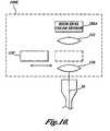
- a color calibration mechanismallows the response of the system to be calibrated for optical characteristics of different endoscopes and/or other image signal path variables.
- FIGS. 1A-1Bare block diagrams of fluorescence endoscopy video systems according to embodiments of the present invention.
- FIG. 2is a block diagram of a multimode light source in accordance with another aspect of the present invention.
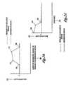
- FIGS. 3A-3Cillustrate a preferred embodiment of the camera that can acquire color; fluorescence/reflectance, and/or fluorescence/fluorescence images according to the present invention with optional placement for collimation and imaging optics;
- FIGS. 4A-4Eillustrate a number of camera beam splitter configurations
- FIG. 5illustrates a second embodiment of a camera according to the present invention
- FIG. 6illustrates a third embodiment of a camera according to the present invention
- FIGS. 7A-7Dillustrate a number of spectral splitter and filter assembly configurations
- FIG. 8illustrates a fourth embodiment of a camera according to the present invention.
- FIG. 9A-9Billustrates examples of spectral splitter and filtering assembly that can transmit images to the same image plane
- FIG. 10illustrates a fifth embodiment of a camera according to the present invention.
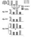
- FIGS. 11A-11Dare graphs illustrating presently preferred transmission characteristics of filters and dichroic splitters for fluorescence/reflectance imaging using green fluorescence light and red reflectance light;
- FIGS. 12A-12Dare graphs illustrating presently preferred transmission characteristics for filters and dichroic splitters for fluorescence/reflectance imaging using green fluorescence light and blue reflectance light;
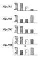
- FIGS. 13A-13Dare graphs illustrating presently preferred transmission characteristics of filters and dichroic splitters for fluorescence/reflectance imaging using red fluorescence light and blue reflectance light;
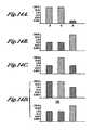
- FIGS. 14A-14Dare graphs illustrating presently preferred transmission characteristics of filters and dichroic splitters for fluorescence/reflectance imaging using red fluorescence light and blue reflectance light;
- FIGS. 15A-15Dare graphs illustrating presently preferred transmission characteristics of filters and dichroic splitters for fluorescence/reflectance imaging using red fluorescence light and near-infrared reflectance light;
- FIGS. 16A-16Dare graphs illustrating presently preferred transmission characteristics of filters and dichroic splitters for fluorescence/reflectance imaging using green fluorescence light and near-infrared reflectance light;
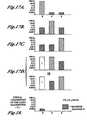
- FIGS. 17A-17Dare graphs showing presently preferred transmission characteristics of filters and dichroic splitters for use with fluorescence/fluorescence imaging
- FIG. 18is a graph illustrating characteristics of a blue blocking filter presently preferred transmission for fluorescence/reflectance or fluorescence/fluorescence imaging using a color image sensor with integrated selective filters.
- FIG. 19is a block diagram of a system to perform color calibration of the fluorescence endoscopy video system according to another aspect of the present invention.
- FIGS. 20-22are graphs showing contrast enhancement tests and functions that can be used to highlight potentially cancerous tissue in accordance with another aspect of the present invention.
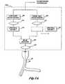
- FIG. 1Ais a block diagram of a fluorescence endoscopy video system 50 in accordance with a presently preferred embodiment of the present invention.
- the systemincludes a multimode light source 52 that generates a white light for obtaining color images.
- the light source 52produces an excitation light for inducing tissue autofluorescence.
- the light source 52produces an excitation light for inducing tissue autofluorescence and a reference reflectance light.
- the use of excitation light and excitation plus reflectance light for fluorescence/fluorescence and fluorescence/reflectance imaging modeswill be described in further detail below.
- Light from the light source 52is supplied to an illumination guide 54 of an endoscope 60 , which then illuminates a tissue sample 58 that is to be imaged.
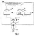
- FIG. 2shows the components of the light source 52 in greater detail.
- the light source 52includes an arc lamp 70 that is surrounded by a reflector 72 .
- the arc lamp 70is a high pressure mercury arc lamp (such as the Osram VIP R 120P24).
- a high pressure mercury lampis currently preferred for its combination of high blue light output, reasonably flat white light spectrum, and small arc size.
- the light from the arc lamp 70is coupled to a light guide 54 of an endoscope 60 through appropriate optics 74 , 76 , and 78 for light collection, spectral filtering and focusing respectively.
- the light from the arc lampis spectrally filtered by one of a number of optical filters 76 A, 76 B, 76 C . . . that operate to pass or reject desired wavelengths of light in accordance with the operating mode of the system.
- optical filter 76 Aeliminates any spectral peaks and modifies the color temperature of the light produced by the arc lamp 70 .
- the transmission characteristics of the light source filters 76 B, 76 C . . . for fluorescence/reflectance and fluorescence/fluorescence imaging modes, respectively,are discussed in conjunction with the characteristics of the camera filters 118 , 119 A, 119 B . . . below.
- An intensity control 80 that adjusts the amount of light transmitted along the light pathis positioned at an appropriate location between the arc lamp 70 and the endoscope light guide 54 and controls the amount of light coupled to the light guide 54 .
- a shutter mechanism 82may be positioned in the same optical path in order to block any of the light from the lamp from reaching the light guide.
- a controller 86operates an actuator that moves the filters 76 A, 76 B, or 76 C into and out of the light path. The controller 86 also controls the position of the intensity control 80 and the operation of the shutter mechanism 82 .
- the systemalso includes a multimode camera 100 .
- the light that is collected from the tissue by the endoscope 60is transmitted through an image guide 56 and is projected into the multimode camera 100 .
- fluorescence endoscopyis generally used as an adjunct to white light endoscopy, each of the various embodiments of the camera described below may be used both for color and fluorescence/reflectance and/or fluorescence/fluorescence imaging.
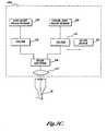
- FIG. 1Bis a block diagram of an alternative fluorescence endoscopy video system 50 , which differs from that shown in FIG. 1A , in that the multimode camera 100 is located at the insertion end of the endoscope and the endoscope does not contain image guide 56 .
- the resulting endoscope 60can be characterized as a fluorescence video endoscope, similar to video endoscopes currently on the market (such as the Olympus CF-240L) in utility, but with the additional ability to be utilized for both color and fluorescence/reflectance and/or fluorescence/fluorescence imaging.
- FIG. 1Bis identical to that shown in FIG. 1A .
- the various embodiments of the camera described belowlend themselves to implementation in a fluorescence video endoscope due to their compactness.
- the multimode camera 100directly collects the light emitted by the tissue.
- the inherent advantages of a video endoscopecan be obtained: namely, the light available to form an image and the image resolution are improved compared to the case when the image is transmitted outside the body through an endoscope imaging guide.
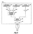
- a camera 100 Areceives light from the image guide 56 of an endoscope 60 and directs the light towards a color image sensor 102 and a low light image sensor 104 .
- lightis typically directed to either of the two image sensors 102 or 104 with a movable mirror that is selectively inserted into the optical path.
- a movable mirrormust be carefully constructed so that it moves within tight tolerances. This adds greatly to the complexity and cost of the camera. The need to maintain these tight tolerances throughout the lifetime of the system also decreases the camera's reliability.
- the camera 100 Areplaces the moving mirror with a fixed optical beam splitter 106 that splits the incoming light into two beams.
- the light beamis split such that a smaller proportion of the light received from the endoscope 60 is directed towards the color image sensor 102 and a larger proportion of the incoming light is directed towards the low light image sensor 104 .
- the beam splittermay be a standard commercially available single plate 88 , single cube 89 , or single pellicle design 90 , as shown in FIGS. 4A-4C .
- the optical path between the endoscope 60 and image sensorscontains an uneven number of reflections (e.g., such as from a single component beam splitter), the image projected onto the sensor will be left-to-right inverted. The orientation of such images will need to be corrected by image processing.
- the optical beam splitter 106may be a combination of simple components or a custom prism design as shown in FIGS. 4D-4E .
- the cube assembly shown in FIG. 4Dis an example of standard, commercially available glass components (beam splitter cube 89 , right angle prism 91 , and simple glass block 92 ) that have been combined into an assembly.
- the glass block 92is positioned behind the right angle prism 91 to compensate for the different path lengths such that both beams are focused in the same image plane.
- the custom prism shown in FIG. 4Eis comprised of three prisms.
- a first partially-mirrored surface 95 on a first prismdirects a portion of the incoming light toward a fully reflective surface 96 on the first prism.
- Light reflected off the surface 96passes through a second prism 99 .
- Light passing through the partially-mirrored surface 95is reflected off fully reflective surfaces 97 and 98 of a third prism.
- the optical path length of the beam that is reflected by the partially mirrored surface 95is the same as the optical path of the light that passes through the partially-mirrored surface 95 .
- the custom prism shown in FIG. 4Ehas the advantage that it is more compact than the cube assembly and that it provides a continuous surface from which the image sensor(s) may be located.
- the two paths for the split imagecontain an even number of reflections and are optically equivalent in length. In the case of an optical imaging configuration as described in FIG. 3C below, this allows both images to be projected into the same image plane (e.g., such as would be required if both images were imaged with a single image sensor).
- light collimating optics 110are positioned between the endoscope 60 and beam splitter 106 , and imaging optics 112 and 114 are positioned immediately preceding the color image sensor 102 and the low light image sensor 104 , respectively.
- the collimating optics 110have been eliminated. Such a configuration is preferable to that in FIG. 3A , if the light beam from the endoscope 60 is already collimated.
- FIG. 3CThe presently preferred configuration of the camera 100 A is shown in FIG. 3C .
- the collimating optics 110have been eliminated and replaced with a single set of imaging optics 113 located between the endoscope 60 and beam splitter 106 .
- the advantage of this configurationis that all imaging is performed and controlled by the same imaging optics 113 .
- Such a configurationrequires all beam paths to have the same optical path length, however, and this restriction must be considered in the design of the beam splitter 106 and a pair of spectral filters 118 and 119 that are located in the path to the image sensors 102 and 104 .
- Glass block 121is inserted into the optical path when spectral filter 119 is removed.
- a spectral filter 118is located in the optical path between the beam splitter 106 and the low light image sensor 104 .
- the spectral filter 118may be incorporated as an element of the beam splitter 106 .
- a second spectral filter 119is positioned so that it can be moved into and out of the optical path between the beam splitter 106 and the color image sensor 102 .
- a glass block 121 with the same optical path length as filter 119is moved into position between the beam splitter 106 and the color image sensor 102 to maintain a constant optical path length.
- this insertable spectral filter 119 and glass block 121may be incorporated elsewhere in the optical path between the endoscope 60 and the color image sensor 102 . Moving a filter into and out of an optical path can be done with a simple mechanism as there are no stringent mechanical and optical requirements like those for moving a mirror.
- the low light image sensor 104preferably comprises a monochrome charge coupled device (CCD), monochrome charge coupled device with charge carrier multiplication (such as the Texas Instruments TC253 or the Marconi Technologies CCD65), intensified charge coupled device (ICCD), charge injection device (CID), charge modulation device (CMD), complementary metal oxide semiconductor image sensor (CMOS) or electron beam charge coupled device (EBCCD) type of sensor.
- the color image sensor 102is preferably a color CCD, a color CCD with charge carrier multiplication, a three-CCD color image sensor assembly with charge carrier multiplication, a three-CCD color image sensor assembly, a color CMOS image sensor, or a three-CMOS color image sensor assembly.
- the systemalso includes a processor/controller 64 and a video monitor 66 .
- the processor/controller 64receives the transduced image signals from the camera 100 and digitizes and processes these signals. The processing of these signals may include the application of certain contrast enhancement algorithms described below. The processed signals are then encoded in a video format and displayed on a color video monitor 66 .
- the processor/controller 64also provides control functions for the fluorescence endoscopy video system. These control functions include providing control signals that
- This normalizationmay be performed by assigning each of the two image signals a different display color, e.g., by supplying the image signals to different color inputs of a color video monitor.
- the two imagesWhen displayed on a color video monitor, the two images are effectively combined to form a single image, the combined color of which represents the relative strengths of the signals from the two images. Since the color of the combined image is independent of the absolute strength of the separate image signals, the color will not change as a result of changes in the distance or angle of the endoscope 60 to the tissue sample 58 or other imaging geometry factors. If, however, there is a change in the shape of the autofluorescence spectrum of the observed tissue that gives rise to a change in the relative strength of the two image signals, such a change will be represented as a change in the color of the displayed image.
- the mixture of colors with which normal tissue and tissue suspicious for early cancer are displayeddepends on the gain applied to each of the two separate image signals. There is an optimal gain ratio for which tissue suspicious for early cancer in a fluorescence image will appear as a distinctly different color than normal tissue. This gain ratio is said to provide the operator with the best combination of sensitivity (ability to detect suspect tissue) and specificity (ability to discriminate correctly). If the gain applied to the reference image signal is too high compared to the gain applied to the fluorescence image signal, the number of tissue areas that appears suspicious but whose pathology turns out to be normal, increases. Conversely, if the relative gain applied to the reference image signal is too low, sensitivity decreases and suspect tissue will appear like normal tissue. For optimal system performance, therefore, the ratio of the gains applied to the image signals must be maintained at all times.
- In vivo spectroscopyhas been used to determine which differences in tissue autofluorescence and reflectance spectra have a pathological basis.
- the properties of these spectradetermine the particular wavebands of autofluorescence and reflected light required for the fluorescence/reflectance imaging mode, or the particular two wavebands of autofluorescence required for fluorescence/fluorescence imaging mode. Since the properties of the spectra depend on the tissue type, the wavelengths of the important autofluorescence band(s) may depend on the tissue being imaged and the location within those tissues.
- the specifications of the optical filters described beloware a consequence of these spectral characteristics, and are chosen to be optimal for the tissues to be imaged.
- the camera 100 shown in FIG. 1is capable of color, fluorescence/reflectance, and fluorescence/fluorescence imaging modes.
- the processor/controller 64provides a control signal to the multimode light source 52 that it should be in white light mode.
- the light source 52selects and positions the appropriate optical filter 76 A into the optical path between the arc lamp 70 and the endoscope light guide 54 .
- This filter 76 Aremoves any spectral peaks and adjusts the color temperature of the light produced by the arc lamp 70 .
- the filtered light from the light source 52is projected into the endoscope light guide 54 and is transmitted to the tip of the endoscope 60 to illuminate the tissue 58 .
- the processor/controller 64also ensures that the camera is in the correct imaging mode to avoid damage to the sensitive low light image sensor 104 .
- the low light image sensor 104is an ICCD, for example, the voltage across the photocathode is set to zero.
- the light reflected by the tissue 58is collected by the endoscope image guide 56 and is projected through the camera beam splitter 106 onto the color image sensor 102 .
- Spectral filter 119is removed from the optical path during this imaging mode and replaced by glass block 121 (if required).
- the color imageis transduced by the color image sensor 102 and the resulting image signal is transmitted to the processor/controller 64 .
- the processor/controller 64Based on the brightness of the color image, the processor/controller 64 provides a control signal to the multimode light source 52 to adjust the intensity control 80 and thereby adjust the level of light output by the endoscope 60 .
- the processor/controller 64may also send a control signal to the camera 100 to adjust the gain of the color image sensor 102 .
- the color imageAfter being processed, the color image is displayed on the video monitor 66 . All of the imaging operations occur in real-time, that is to say they occur at analog video display rates (30 frames-per-second for NTSC format, and 25 frames-per-second for PAL format).
- the processor/controller 64When switching to the fluorescence/reflectance imaging mode, the processor/controller 64 provides a control signal to the multimode light source 52 to indicate that it should be in fluorescence/reflectance mode.
- the light source 52selects and positions the appropriate optical filter 76 B into the optical path between the arc lamp 70 and the endoscope light guide 54 .
- This filter 76 Btransmits those wavelengths of light that will induce the tissue 58 under examination to fluoresce. It also transmits reference reflectance light in either the green or red portions of the visible spectrum or alternatively, the blue excitation light can be utilized for the reference. All other wavelengths of light are blocked as described below.
- the filtered lightis then projected into the endoscope light guide 54 and is transmitted to the tip of the endoscope 60 to illuminate the tissue 58 .
- the processor/controller 64also ensures that the camera 100 is in the correct imaging mode by providing power to the low light image sensor 104 .
- the fluorescence emitted and reference light reflected by the tissue 58 , along with the reflected excitation light,are collected by the endoscope image guide 56 and are projected through the camera beam splitter 106 onto the low light image sensor 104 and the color image sensor 102 .
- Spectral filter 118limits the light transmitted to the low light image sensor 104 to either green or red autofluorescence light only and blocks the light in the excitation and reference wavebands transmitted by light source filter 76 B.
- Spectral filter 119is inserted into the optical path of the color image sensor 102 during this imaging mode and transmits only the reflected reference waveband light.
- the reflectance light transmission specifications of filter 119 and light source filter 76 Bare chosen such that the intensity of the reflected light at the color image sensor 102 results in a transduced image signal with good signal-to-noise characteristics and without significant saturation, while at the same time allowing for excitation of sufficient autofluorescence for imaging. (Note that if spectral filter 119 was located between the beam splitter 106 and the endoscope 60 , it would also have to transmit the autofluorescence light detected by the low light image sensor 104 .) The autofluorescence image is then transduced by the low light image sensor 104 , the reference image is transduced by the color image sensor 102 , and the resulting image signals are transmitted to the processor/controller 64 .
- the processor/controller 64may provide a control signal to the multimode light source 52 to adjust the intensity control 80 and thereby adjust the level of light delivered to the endoscope 60 .
- the processor/controller 64may also send control signals to the camera 100 to adjust the gains of the low light image sensor 104 and the color image sensor 102 in order to maintain constant image brightness while keeping constant relative gain, as described in more detail below.
- the images from the two sensorsare combined into a single image, which is displayed on the video monitor 66 . Again, all of the imaging operations occur in real-time.
- Calibration of the signal responsemay be implemented in the processor/controller 64 .
- the gain response of the fluorescence image sensor and reference image sensorare characterized, and those response characteristics are utilized to establish a constant gain ratio between the fluorescence and reference image signal paths.
- the entire signal pathmust be considered.
- the gains applied to the image signals over the remainder of the image signal pathi.e., excluding the image sensors
- maintaining a constant system image signal gain ratiois reduced to establishing a constant gain ratio between the two image sensors.
- the calibration method described hereinis for the preferred sensor types: an ICCD for the low light image sensor 104 , and a color CCD for the color image sensor 102 .
- the gain of an ICCD sensoris typically controlled by varying an analog gain control signal (G).
- Gan analog gain control signal
- a gain control signaloperates on the accelerating voltage that controls the light signal amplification in the intensifier's multichannel plate.
- the gaincan be varied over about four orders of magnitude of light intensity.
- K ICCDK 0 ⁇ e f ICCD (G)
- K 0is the overall gain of the ICCD with the gain control setting at zero
- f ICCD (G)a 1 ⁇ G+a 2 ⁇ G 2 +a 3 ⁇ G 3 is a quasilinear function approximated by a polynomial whose coefficients a i are determined by empirical measurements of the response of the ICCD with varying gain.
- the gain of a color CCDcan be controlled in two ways: 1) by changing the electronic shutter time (typically in discrete steps) which allows variation in sensitivity over about three orders of magnitude in light intensity, and 2) by changing an analog electronic gain control which allows variation in sensitivity over about one order of magnitude in light intensity.
- the analog electronic gaintypically varies exponentially with a control voltage (R).
- K CCDK 60 ⁇ A shutter ⁇ e f CCD (R)
- K 60is the overall CCD gain with the electronic shutter at the standard video field rate (e.g., 1/60 second for NTSC video) and with the control voltage set to zero
- a shutteris the attenuation provided by the electronic shutter
- the gain of the CCDcan be adjusted to accommodate a wide range in light intensity by varying A shutter , which provides step-wise variation over a wide range, in combination with R, which allows continuous variation over a small range.
- This constant gain ratiocan be implemented by designating one image sensor as the “master.” For a given gain setting of the “master” image sensor, the gain setting of the other image sensor (the “slave”) is determined by solving Equation 1 to find the appropriate value of R, A shutter (or G). Either image sensor may be utilized as the master. The choice as to which image sensor is utilized as the master and which the slave depends on factors such as which image signal predominates in the digital domain of the image processor, the technique for solving the equation, and on the time it takes each image sensor to respond to a change in gain.
- the gain calibration method required for other types of image sensorsutilizes the same principles, including starting with an equation describing the gain of each sensor in terms of controllable parameters, calculating the ratio of the gain equations, assuming the gain ratio is constant, and solving the gain ratio equation for the parameters of one sensor in terms of the parameters of the other sensor and the constant, and can be derived in a similar manner.
- the operation of the systemis similar to that of fluorescence/reflectance mode, so only the points of difference will be described.
- the light source 52selects and positions the appropriate optical filter 76 C into the optical path between the arc lamp 70 and the endoscope light guide 54 .
- This filter 76 Ctransmits substantially those wavelengths of light that will induce the tissue 58 under examination to fluoresce.
- the autofluorescence emitted by the tissue 58is collected by the endoscope image guide 56 and is projected through the camera beam splitter 106 onto the low light image sensor 104 and the color image sensor 102 .
- Spectral filter 118limits the light transmitted to the low light image sensor 104 to either green or red autofluorescence light only and excludes light in the excitation waveband.
- Spectral filter 119is inserted into the optical path to the color image sensor 102 during this imaging mode and transmits only the autofluorescence light in the waveband not transmitted to the low light image sensor 104 .
- the autofluorescence imagesare then transduced by the low light image sensor 104 and the color image sensor 102 and the resulting image signals are transmitted to the processor/controller 64 . After being processed, the images from the two sensors are combined into a single fluorescence/fluorescence image, which is displayed on the video monitor 66 .
- the image sensor gainsare controlled in the same calibrated fashion as for fluorescence/reflectance imaging.
- the autofluorescence image detected with the color image sensor 102will be very dim, the images obtained with this type of sensor will likely not be acquired, processed and displayed in real-time unless some form of signal amplification (e.g., pixel binning, CCD with charge carrier multiplication, etc.) is provided.
- some form of signal amplificatione.g., pixel binning, CCD with charge carrier multiplication, etc.
- images from both sensorscould be time-averaged and combined before being displayed.
- the camera 100 B for this embodiment of a fluorescence endoscopy video systemis as shown in FIG. 5 . It differs from the camera in the first embodiment in that all imaging modes utilize a single, high sensitivity color image sensor 102 A, preferably a CCD with charge carrier multiplication, a three-CCD image sensor assembly with charge carrier multiplication, a color CCD, a three-CCD color image sensor assembly, a color CMOS image sensor, or a three-CMOS color image sensor assembly.
- a single, high sensitivity color image sensor 102 Apreferably a CCD with charge carrier multiplication, a three-CCD image sensor assembly with charge carrier multiplication, a color CCD, a three-CCD color image sensor assembly, a color CMOS image sensor, or a three-CMOS color image sensor assembly.
- two imagesare projected onto the sensor 102 A simultaneously.
- the imagesare separated and processed by the image processor 64 and displayed according to the imaging mode of the system.
- color imaging modethe color image is separated from the other images, processed and displayed on the video monitor 66 .
- filter 119is moved out of the light path and glass block 121 , if required, is moved into position.
- fluorescence/reflectance and fluorescence/fluorescence imaging modesthe fluorescence and reference images are first separated by the image processor 64 , processed, and then are again superimposed on the video monitor 66 by applying each image to a different monitor color input.
- the gain ratio of the two image signalsis determined and maintained by the transmission characteristics of filters 118 and 119 in the camera, and 76 B or 76 C in the light source.
- the image processor 64may also be utilized to implement small changes in the gain ratio by changing the brightness of one image with respect to the other during processing.
- the autofluorescence images detected with the color image sensor 102 Awill be very dim, and so the images obtained with this type of sensor will likely not be acquired, processed, and displayed in real-time unless some form of signal amplification (e.g., pixel binning, color CCD with charge carrier multiplication, etc.) is provided.
- some form of signal amplificatione.g., pixel binning, color CCD with charge carrier multiplication, etc.
- the cameramay be used to image autofluorescence in a non-real time mode.
- This configuration of the cameraalso adds an additional restriction to the design of the optical subsystem.
- the effect of this restrictionnecessitates that either imaging optical component 112 differs from imaging optical component 114 in such a way that both images are projected onto the same image plane, or that beam splitter 106 , after splitting the light from the endoscope 60 , utilizes substantially equal optical path lengths for both beams and, in conjunction with similar imaging optical components 112 and 114 , projects both images onto the same image plane.
- Such a beam splitter 106requires a multicomponent or custom beam splitter 106 of the type shown in FIGS. 4D-E .
- the beam splitters shown in these drawingsalso anticipate the need for an equal optical path length, as described for the imaging optics configuration in FIG. 3C .
- the camera 100 C for this embodiment of a fluorescence endoscopy video systemis as shown in FIG. 6 . It differs from the camera 100 A in the first embodiment in that the color image sensor 102 is utilized only for the color imaging mode. As a consequence, filter 119 has been removed from the color image sensor optical path, which also eliminates the need for a filter moving mechanism. Instead, the light that is not being projected towards the color image sensor 102 after being split by the beam splitter 106 is projected towards a dichroic splitting and filtering assembly 120 . This assembly 120 further splits and filters the light from the beam splitter 106 into two spectral components.
- a dichroic splitter 120divides the incoming light spectrally, so that certain wavelengths are reflected while others are transmitted. Further filtering may then be applied to this spectrally divided light beam.
- the dichroic splitting and filtering assembly 120may comprise a cube dichroic 130 or a plate dichroic 133 .
- Spectral filters 118 , 119may be positioned away from the dichroic mirrors or, in the case of the cube, may be formed as a coating on the cube.
- a reflecting mirror 140may be used to invert the image reflected off the dichroic mirror.
- the dichroic splittermay be configured as a custom prism assembly as shown in FIG. 9 .
- the optical path between the endoscope 60 and image sensorscontains an uneven number of reflections (e.g., such as from a single component beam splitter or dichroic), the image projected onto the sensor will be left-to-right inverted. The orientation of such images will need to be corrected by image processing.
- the reference sensor 105preferably comprises a monochrome CCD, monochrome CCD with charge carrier multiplication, ICCD, CID, CMD, CMOS or EBCCD-type sensor, but it may also be a color CCD, a three-CCD color image sensor assembly, a color CCD with charge carrier multiplication, a three-color CCD image sensor assembly with charge carrier multiplication, a color CMOS image sensor, or a three-CMOS color image sensor assembly.
- the cameramay combine a real-time autofluorescence image (from the low light image sensor 104 ) with a time-averaged image from the referenced sensor 105 , or may provide all autofluorescence images in non-real time mode.
- Calibration of the light signal path for this embodimentis similar to that of the first embodiment for the preferred choice of image sensors, in which an ICCD is the low light image sensor 104 and a CCD is the reference image sensor 105 .
- the reference image sensoris also an intensified sensor such as an ICCD or EBCCD, the equation describing the gain ratio for the two sensors is slightly different.
- K ICCDK 0 ⁇ e f ICCD (G)
- K 0the overall gain of the ICCD with the gain control setting at zero
- Gthe intensifier gain signal
- f ICCD (G)a 1 ⁇ G+a 2 ⁇ G 2 +a 3 ⁇ G 3 is a quasilinear function approximated by a polynomial whose coefficients a i are determined by empirical measurements of the response of the ICCD with varying gain.
- K 0 ref ⁇ e f ICCD ref ⁇ ( G ref )const . ( 2 )
- the gain setting G fluor (or G ref ) of one image sensoris determined by an automatic gain control.
- the gain setting of the other image sensoris determined by solving Equation 2 to find the appropriate value of G ref (or G fluor ).
- either image sensormay be utilized as the master.
- the camera 100 D for this embodiment of a fluorescence endoscopy video systemis as shown in FIG. 8 . It differs from the camera 100 C in the third embodiment in that the low light image sensor 104 is utilized to image both the first fluorescence image as well as the reference fluorescence or reflectance image.
- the dichroic assembly 120may include a right angle prism 131 and a glass block 132 that compensate for the differing optical path lengths as shown in FIG. 9A .
- the dichroic assembly 120may include a number of prisms having partially and fully reflective surfaces in the same configured manner as the beam splitter shown in FIG. 4E , except that the partially reflecting surface 95 is replaced with a dichroic mirror surface.
- the imaging optical component 114 Adiffers from imaging optical component 114 B in such a way that both images are projected onto the same image plane.
- the transmission of the filter used for the reference reflectance image (e.g., 114 B) and light source filter 76 B in FIG. 2is chosen in such a way that the intensity of the reference reflected image at sensor 104 is similar to that of the fluorescence image for all possible excitation light intensities.
- the images transduced by the low light image sensor 104are separated by the image processor 64 , are processed, and then are again superimposed on the video monitor 66 by applying each image to a different monitor color input.
- a fluorescence endoscopy video system utilizing this embodimentis calibrated in a similar manner to that described in the second embodiment to maintain constant gain ratio.
- the camera 100 E for this embodiment of a fluorescence endoscopy video systemis as shown in FIG. 10 . It differs from the camera 100 A in the first embodiment in that all imaging modes utilize a single, high sensitivity color image sensor 102 A. It differs from the camera in the second embodiment in that the beam splitter is removed and the need for spectral filters 118 and 119 is eliminated.
- Each of the pixel elements on the high sensitivity color sensor 102 Ais covered by an integrated filter, typically red, green, or blue. These filters block the reflected excitation light and allow the fluorescence and reflectance light to reach the pixel elements.
- a separate blue blocking filter 118 ′can be provided.
- the blue blocking filter 118 ′is a long pass filter that blocks light at blue and shorter wavelengths and transmits light at green and longer wavelengths.
- the intensity of the reflected excitation lightis reduced to the point that the integrated filters on the pixel elements provide sufficient further filtering to define the wavelengths of fluorescence and reflectance light that reach the high sensitivity color sensor 102 A.
- the primary fluorescence and reference imagesare superimposed over the same area of the image sensor 102 A but, because of the individual filters placed over each pixel, these images are detected by different sensor pixels. Separate primary fluorescence and reference image signals can then be created by the image processor 64 from the single CCD image signal.
- the blue blocking filter 118 ′is removed from the light path and, if required, glass block 121 is moved into position.
- the color imageis processed by image processor 64 and displayed on the video monitor 66 .
- the fluorescence and reference imagesare processed by image processor 64 and superimposed on the video monitor 66 by applying each image to a different color input of the monitor.
- the way in which this embodiment is calibrated to maintain constant relative gainis similar to that described for the second embodiment.
- the reference light transmission specifications of both the light source filter 76 B or 76 C and the selective color filters integrated with the image sensor 102 Aare chosen such that the intensity of the reflected light at the color image sensor active elements results in a transduced image signal with good signal-to-noise characteristics and without significant saturation. At the same time these filters must have appropriate light transmission specifications for excitation and imaging of the primary fluorescence. The filter transmission characteristics must further be chosen to provide the desired ratio of relative primary fluorescence to reference light intensity at the image sensor.
- the autofluorescence images detected with the color image sensorwill be very dim, and so the images obtained with this type of sensor will likely not be acquired, processed and displayed in real-time unless some form of signal amplification (e.g., pixel binning, CCD with charge carrier multiplication, etc.) is provided.
- some form of signal amplificatione.g., pixel binning, CCD with charge carrier multiplication, etc.
- the cameramay be used to image autofluorescence in non-real time mode.
- each of the embodiments of the camera described aboveare lighter in weight than prior art because no more than one low light image sensor 104 is required. Since such sensors are often heavy, bulky and expensive, the size and cost of the camera is significantly reduced. Furthermore, because a fixed beam splitter 106 is used instead of a movable mirror, the cameras are more robust and can be made less expensively.
- the filters in the light source and camerashould be optimized for the imaging mode of the camera, the type of tissue to be examined, and/or the type of pre-cancerous tissue to be detected.
- all of the filters described belowcan be obtained made to order using standard, commercially available components, the appropriate wavelength range of transmission and degree of blocking outside of the desired transmission range for the described fluorescence endoscopy images modes are important to the proper operation of the system. The importance of other issues in the specification of such filters such as the fluorescence properties of the filter materials and the proper use of anti-reflection coatings are taken to be understood.
- FIGS. 11-14illustrate the preferred filter characteristics for use in a fluorescence endoscopy video system operating in fluorescence/reflectance imaging mode wherein both tissue autofluorescence is being excited and imaged and a reference reflectance light is being reflected and imaged.
- fluorescence endoscopy video systemsoperating in the fluorescence/reflectance imaging mode including green fluorescence with either red or blue reflectance, and red fluorescence with either green, blue, or near-infrared reflectance. The particular configuration utilized depends on the target clinical organ and application. The filter characteristics will now be described for each of these four configurations.
- FIGS. 11A-11Dillustrate the preferred composition of the light transmitted by filters for a green fluorescence and red reflectance imaging mode.
- FIG. 11Aillustrates the composition of the light transmitted by the light source filter, such as filter 76 B, which is used to produce blue excitation light and red reference light.
- This filtertransmits light in the blue wavelength range from 370-460 nm, or any subset of wavelengths in this range. It also transmits light in the red wavelength range of 590-750 nm, or any subset of wavelengths in this range.
- the light transmitted in the red wavelength range (or subset of that range)is adjusted, as part of the system design, to be an appropriate fraction of the light transmitted in the blue wavelength range.
- This fractionis selected to meet the need to match the intensity of the reflected reference light projected on the color image sensor to the requirements of the sensor, at the same time as maintaining sufficient fluorescence excitation.
- less than 0.001%is in the green wavelength range of 480-570 nm (or whatever desired subset of this range is specified as the transmission range of the green fluorescence filter described below).
- FIG. 11Bshows the composition of the light transmitted by a camera filter, such as spectral filter 118 , for imaging the green fluorescence image.
- the filterblocks the blue excitation light and red reflectance light while transmitting green fluorescence light in the wavelength range of 480-570 nm, or any subset of wavelengths in this range.
- the filter characteristicsare such that any light outside of the wavelength range of 480-570 nm (or any desired subset of wavelengths in this range) contributes no more than 0.1% to the light transmitted by the filter.
- FIG. 11Cshows the composition of the light transmitted by a camera filter, such as spectral filter 119 , for imaging the red reflectance image.
- the filterblocks the blue excitation light and green fluorescence light while transmitting red reflectance light in the wavelength range of 590-750 nm, or any desired subset of wavelengths in this range.
- the filter characteristicsare such that any light outside of the wavelength range of 590-750 nm (or any desired subset of wavelengths in this range) contributes no more than 0.1% to the light transmitted by the filter.
- the reference image sensoris a color image sensor, such as a color CCD
- further filteringmay be obtained from the color filters integrated with the sensor.
- the in-band transmission characteristicsare determined by the need to match the intensity of the reflected reference light projected onto the color image sensor to the requirements of the sensor, in combination with the characteristics of the light source filter described above.
- FIG. 11Dshows the composition of the light transmitted by a dichroic mirror of the kind that may be employed in the dichroic splitter and filter assembly 120 .
- the dichroic mirrorpreferably has a half-maximum transmission in the range of 570-590 nm. It may reflect the shorter wavelengths and transmit the longer wavelengths (long pass) or transmit shorter wavelengths and reflect longer wavelengths (short pass).
- the dichroic splitter and filter assemblymay incorporate the filters shown in FIGS. 11B and 11C .
- FIGS. 12A-12Dillustrate the preferred composition of the light transmitted by filters for a green fluorescence and blue reflectance imaging mode.
- FIG. 12Aillustrates the composition of the light transmitted by a light source filter which is used to produce excitation light, such as filter 76 B described above.
- the wavelengths of the imaged reflectance lightare contained within the range of blue excitation wavelengths.
- the filtertransmits light in the wavelength range from 370-460 nm, or any subset of wavelengths in this range, but it is not required to transmit any light in the red wavelength range. Of the light transmitted by this filter, less than 0.001% is in the green wavelength range of 480-570 nm (or whatever desired subset of this range is specified as the transmission range of the green fluorescence filter described below).
- FIG. 12Bshows the composition of the light transmitted by a camera filter for imaging the green fluorescence image, such as spectral filter 118 .
- the composition of the light transmitted by this filterhas the same characteristics as the light described in FIG. 11B .
- FIG. 12Cshows the composition of the light transmitted by a camera filter, such as filter 119 , for imaging the blue reflectance image.
- the filterblocks the green fluorescence light while transmitting blue reflectance light in the wavelength range of 370-460 nm, or any desired subset of wavelengths in this range.
- the transmission of this filtermay need to be restricted so as to prevent the large amount of reflected blue light from overwhelming the sensor.
- the filter characteristicsare such that any light outside of the wavelength range of 370-460 nm, or any desired subset of wavelengths in this range, contributes no more than 0.1% to the light transmitted by the filter.
- the reference image sensoris a color image sensor, such as a color CCD, then further filtering of the reflected blue light may be obtained from the color filters integrated with the sensor.
- FIG. 12Dshows the composition of the light transmitted by a dichroic mirror of the kind that may be employed in the dichroic splitter and filter assembly 120 .
- the dichroic mirrorpreferably has a half-maximum transmission in the range of 460-480 nm. It may reflect the shorter wavelengths and transmit the longer wavelengths (long pass) or transmit shorter wavelengths and reflect longer wavelengths (short pass).
- the dichroic splitter and filter assemblymay incorporate the filters shown in FIGS. 12B and 12C .
- FIGS. 13A-13Dillustrate the preferred composition of the light transmitted by filters for a red fluorescence and blue reflectance imaging mode.
- FIG. 13Aillustrates the composition of the light transmitted by a light source filter, such as filter 76 B, which is used to produce blue excitation light. This filter transmits light in the wavelength range from 370-460 nm, or any subset of wavelengths in this range. Of the light transmitted by this filter, less than 0.001% is in the red fluorescence imaging wavelength range of 590-750 nm (or whatever desired subset of this range is specified as the transmission range of the red fluorescence filter described below).
- FIG. 13Bshows the composition of the light transmitted by a camera filter, such as spectral filter 118 , for imaging the red fluorescence image.
- the filterblocks the blue excitation light, while transmitting red fluorescence light in the wavelength range of 590-750 nm, or any subset of wavelengths in this range.
- the filter characteristicsare such that any light outside of the wavelength range of 590-750 nm, or any desired subset of wavelengths in this range, contributes no more than 0.1% to the light transmitted by the filter.
- FIG. 13Cshows the composition of the light transmitted by a camera filter, such as filter 119 , for imaging the blue reflectance image.
- the composition of the light transmitted by this filterhas the same characteristics as the light described in FIG. 12C .
- FIG. 13Dshows the composition of the light transmitted by a dichroic mirror of the kind that may be employed in the dichroic splitter and filter assembly 120 to split the red fluorescence and blue reflectance.
- the dichroic mirrorpreferably has a half-maximum transmission in the range of 460-590 nm. It may reflect the shorter wavelengths and transmit the longer wavelengths (long pass) or transmit shorter wavelengths and reflect longer wavelengths (short pass).
- the dichroic splitter and filter assemblymay incorporate the filters described in FIGS. 13B and 13C .
- FIGS. 14A-14Dillustrate the preferred composition of the light transmitted by filters for a red fluorescence and green reflectance imaging mode.
- FIG. 14Aillustrates the composition of the light transmitted by a light source filter which is used to produce excitation light, such as filter 76 B described above. This filter transmits light in the blue wavelength range from 370-460 nm, or any subset of wavelengths in this range. It also transmits light in the green wavelength range of 480-570 nm, or any subset of wavelengths in this range. The light transmitted in the green wavelength range (or subset of that range) is adjusted, as part of the system design, to be an appropriate fraction of the light transmitted in the blue wavelength range.
- This fractionis selected to meet the need to match the intensity of the reflected reference light projected on the color image sensor to the requirements of the sensor, at the same time as maintaining sufficient fluorescence excitation.
- less than 0.001%is in the red fluorescence imaging wavelength range of 590-750 nm (or whatever desired subset of this range is specified as the transmission range of the red fluorescence filter described below).
- FIG. 14Bshows the composition of the light transmitted by a camera filter, such as spectral filter 118 , for imaging the red fluorescence image.
- the filterblocks the blue excitation light and green reflectance light while transmitting red fluorescence light in the wavelength range of 590-750 nm, or any subset of wavelengths in this range.
- the filter characteristicsare such that any light outside of the wavelength range of 590-750 nm, or any desired subset of wavelengths in this range, contributes no more than 0.1% to the light transmitted by the filter.
- FIG. 14Cshows the composition of the light transmitted by a camera filter, such as filter 119 , for imaging the green reflectance image.
- the filterblocks the blue excitation light and red fluorescence light while transmitting green reflectance light in the wavelength range of 480-570 nm, or any desired subset of wavelengths in this range.
- the in-band transmission characteristicsare determined by the need to match the intensity of the reflected reference light projected onto the color image sensor to the requirements of the sensor, in combination with the characteristics of the light source filter described above.
- the filter characteristicsare such that any light outside of the wavelength range of 480-570 nm, or any desired subset of wavelengths in this range, contributes no more than 0.1% to the light transmitted by the filter.
- FIG. 14Dshows the composition of the light transmitted by a dichroic mirror of the kind that may be employed in the dichroic splitter and filter assembly 120 to split the red fluorescence and green reflectance.
- the composition of the light transmitted by this filterhas the same characteristics as the light described in FIG. 11D .
- FIGS. 15A-15Dillustrate the preferred composition of the light transmitted by filters for a red fluorescence and near-infrared reflectance imaging mode.
- FIG. 15Aillustrates the composition of the light transmitted by a light source filter, which is used to produce excitation light such as filter 76 B described above. This filter transmits light in the blue wavelength range from 370-460 nm, or any subset of wavelengths in this range. It also transmits light in the near-infrared wavelength range of 700-850 nm, or any subset of wavelengths in this range.
- the light transmitted in the near-infrared wavelength range(or subset of that range) is adjusted, as part of the system design, to be an appropriate fraction of the light transmitted in the blue wavelength range to meet the need to match the intensity of the reflected reference light projected on the color image sensor to the requirements of the sensor, at the same time as maintaining sufficient fluorescence excitation.
- the red fluorescence imaging wavelength rangeof 590-700 nm (or whatever desired subset of this range is specified as the transmission range of the red fluorescence filter described below).
- FIG. 15Bshows the composition of the light transmitted by a camera filter, such as spectral filter 118 , for imaging the red fluorescence image.
- the filterblocks the blue excitation light and near-infrared reflectance light while transmitting red fluorescence light in the wavelength range of 590-700 nm, or any subset of wavelengths in this range.
- the filter characteristicsare such that any light outside of the wavelength range of 590-700 nm, or any desired subset of wavelengths in this range, contributes no more than 0.1% to the light transmitted by the filter.
- FIG. 15Cshows the composition of the light transmitted by a camera filter, such as filter 119 , for imaging the near-infrared reflectance image.
- the filterblocks the blue excitation light and red fluorescence light while transmitting near-infrared reflectance light in the wavelength range of 700-850 nm, or any desired subset of wavelengths in this range.
- the in-band transmission characteristicsare determined by the need to match the intensity of the reflected reference light projected onto the color image sensor to the requirements of the sensor, in combination with the characteristics of the light source filter described above.
- the filter characteristicsare such that any light outside of the wavelength range of 700-850 nm, or any desired subset of wavelengths in this range, contributes no more than 0.1% to the light transmitted by the filter.
- FIG. 15Dshows the composition of the light transmitted by a dichroic mirror of the kind that may be employed in the dichroic splitter and filter assembly 120 to split the red fluorescence and near-infrared reflectance.
- the dichroic mirrorpreferably has a half-maximum transmission in the range of 690-710 nm. It may reflect the shorter wavelengths and transmit the longer wavelengths (long pass) or transmit shorter wavelengths and reflect longer wavelengths (short pass).
- the dichroic splitter and filter assemblymay incorporate the filters described in FIGS. 15B and 15C .
- FIGS. 16A-16Dillustrate the preferred composition of the light transmitted by filters for a green fluorescence and near-infrared reflectance imaging mode.
- FIG. 16Aillustrates the composition of the light transmitted by a light source filter which is used to produce excitation light, such as filter 76 B described above. This filter transmits light in the blue wavelength range from 370-460 nm, or any subset of wavelengths in this range. It also transmits light in the near-infrared wavelength range of 700-850 nm, or any subset of wavelengths in this range.
- the light transmitted in the near-infrared wavelength range(or subset of that range) is adjusted, as part of the system design, to be an appropriate fraction of the light transmitted in the blue wavelength range to meet the need to match the intensity of the reflected reference light projected on the color image sensor to the requirements of the sensor, at the same time as maintaining sufficient fluorescence excitation.
- the green fluorescence imaging wavelength rangeof 480-570 nm (or whatever desired subset of this range is specified as the transmission range of the red fluorescence filter described below).
- FIG. 16Bshows the composition of the light transmitted by a camera filter, such as spectral filter 118 , for imaging the green fluorescence image.
- the filterblocks the blue excitation light and near-infrared reflectance light while transmitting green fluorescence light in the wavelength range of 480-570 nm, or any subset of wavelengths in this range.
- the filter characteristicsare such that any light outside of the wavelength range of 480-570 nm, or any desired subset of wavelengths in this range, contributes no more than 0.1% to the light transmitted by the filter.
- FIG. 16Cshows the composition of the light transmitted by a camera filter, such as filter 119 , for imaging the near-infrared reflectance image.
- the filterblocks the blue excitation light and green fluorescence light while transmitting near-infrared reflectance light in the wavelength range of 700-850 nm, or any desired subset of wavelengths in this range.
- the in-band transmission characteristicsare determined by the need to match the intensity of the reflected reference light projected onto the color image sensor to the requirements of the sensor, in combination with the characteristics of the light source filter described above.
- the filter characteristicsare such that any light outside of the wavelength range of 700-850 nm, or any desired subset of wavelengths in this range, contributes no more than 0.1% to the light transmitted by the filter.
- FIG. 16Dshows the composition of the light transmitted by a dichroic mirror of the kind that may be employed in the dichroic splitter and filter assembly 120 to split the green fluorescence and near-infrared reflectance.
- the dichroic mirrorpreferably has a half-maximum transmission in the range of 590-660 nm. It may reflect the shorter wavelengths and transmit the longer wavelengths (long pass) or transmit shorter wavelengths and reflect longer wavelengths (short pass).
- the dichroic splitter and filter assemblymay incorporate the filters described in FIGS. 16B and 16C .
- FIGS. 17A-17Dillustrate the preferred composition of the light transmitted by filters for use in a fluorescence endoscopy video system operating in fluorescence/fluorescence imaging mode wherein the tissue autofluorescence being excited and imaged is divided into two spectral bands.
- FIG. 17Aillustrates the composition of the light transmitted by a filter, such as filter 76 C, which is used to produce excitation light in the system light source.
- This filtertransmits light in the wavelength range from 370-460 nm, or any subset of wavelengths in this range. Of the light transmitted by this filter, less than 0.001% is in the fluorescence imaging band from 480-750 nm (or whatever desired subsets of this range are within the specified transmission range of the primary and reference fluorescence image filters described below).
- FIG. 17Bshows the composition of the light transmitted by a camera filter, such as filter 118 , for imaging the primary fluorescence image.
- the filterblocks excitation light and red fluorescence light while transmitting green fluorescence light in the wavelength range of 480-570 nm, or any subset of wavelengths in this range.
- the filter characteristicsare such that any light outside of the wavelength range of 480-570 nm, or any desired subset of wavelengths in this range, contributes no more than 0.1% to the light transmitted by the filter.
- FIG. 17Cshows the composition of the light transmitted by a camera filter for imaging the reference fluorescence image, such as filter 119 .
- the filterblocks excitation light and green fluorescence light while transmitting red fluorescence light in the wavelength range of 590-750 nm, or any subset of wavelengths in this range.
- the filter characteristicsare such that any light outside of the wavelength range of 590-750 nm, or any desired subset of wavelengths in this range, contributes no more than 0.1% to the light transmitted by the filter.
- FIG. 17Dshows the composition of the light transmitted by a dichroic mirror of the kind that may be employed in the dichroic splitter and filter assembly 120 .
- the dichroic mirrorpreferably has a half-maximum transmission in the range of 570-590 nm. It may reflect the shorter wavelengths and transmit the longer wavelengths (long pass) or transmit shorter wavelengths and reflect longer wavelengths (short pass).
- FIG. 18shows the composition of light transmitted by a filter 118 ′ employed for blocking blue light in a camera such as that described in the fifth embodiment and shown in FIG. 10 .
- the filtertransmits light in the range 480-750 nm, or any subset of wavelengths of light in this range. Of the light transmitted by this filter, less than 0.001% is in the fluorescence excitation band from 370-460 nm (or whatever desired subset of this range is within the specified transmission range of the light source filters described above).
- the fluorescence endoscopy video systems described in the above embodimentshave been optimized for imaging endogenous tissue fluorescence. They are not limited to this application, however, and may also be used for photodynamic diagnosis (PDD) applications.
- PDD applicationsutilize photoactive drugs that preferentially accumulate in tissues suspicious for early cancer. Since effective versions of such drugs are currently in development stages, this invention does not specify the filter characteristics that are optimized for such drugs.
- a fluorescence endoscopy video system operating in either fluorescence/fluorescence or fluorescence/reflectance imaging mode as described hereinmay be used to image the fluorescence from such drugs.
- FIG. 19shows a block diagram of the relevant system components involved in the process of self-calibration.
- Light from the light source 52is supplied to an illumination guide 54 of an endoscope 60 and is directed to a fluorescence/reflectance target 59 with known fluorescence and reflectance properties.
- fluorescence and reflectance light from the target 59is collected and transmitted through an image guide 56 of the endoscope to the camera 100 .
- the camera 100operating in the fluorescence/reflectance or fluorescence/fluorescence mode, spectrally splits and transduces images into separate electrical signals, which are then digitized in the image processor/controller 64 .
- the image processor/controller 64quantifies the magnitude of these digitized image signals in terms of image gray levels.
- the error in the quantified value of the signal responsecan be reduced to less than 1%.
- the image processor/controller 64compares the known properties of the target to the quantified signal response and adjusts the gain ratio described previously to the desired constant value. This adjustment compensates for variations in the signal path between the target 59 and image processor/controller 64 , due to factors such as variations in transmission properties of different endoscopes being used with the system and changes in the signal response of the system with age.
- Such self-calibrationensures that the gain ratio is set to a value such that tissue suspicious for early cancer in a fluorescence image will appear as a distinctly different color than normal tissue. This self-calibration could be carried out before every endoscopy.
- the methoduses a reference target 59 that provides suitable known fluorescence and reflectance response to the light from the light source.
- any suitable object with appropriate fluorescence and reflectance propertiescan be used as a reference target.
- a reference target 59can be made by mixing a fluorescent dye(s) and light scattering materials into a liquid.
- the liquid usedmay be a solute (such as methanol) enclosed in a container with an optical window, or alternatively may be a liquid which hardens to form a solid (such as an epoxy).
- the dye(s) usedmust be appropriately soluble in the liquid utilized.
- the fluorescence spectrum and brightness of the target 59is controlled by the choice and concentration of the fluorescence dye (or dyes) contained in the target.
- the fluorescent dye(s)must be chosen such that the light emitted by the light source 52 excites fluorescence light in the green and/or red wave bands defined by the camera filters described above that correspond to a particular imaging mode.
- the fluorescent dye(s)must also be stable with time and not undergo significant photobleaching.
- One such fluorescent dyeis Coumarin #540A.
- the concentration of the fluorescence dye in the targetis chosen such that the emitted fluorescence light produces mid-range signal amplitudes at or near a particular clinically used gain setting.
- the reflectance property of the targetis controlled by the type and concentration of scattering material added to the target.
- the type of scattering materialis chosen for good reflectivity of the reference light in the wavebands defined by the camera filters described above that correspond to a particular fluorescence/reflectance imaging mode.
- the concentration of the scattering material in the targetis chosen such that the reflected reference light produces mid-range signal amplitudes at or near a particular clinically used gain setting.
- the contrast between normal tissue and tissue suspicious for early canceris typically the result of a reduction in the fluorescence signal associated with the disease, which is not matched by a corresponding reduction in the reference signal.
- image areasare therefore characterized by a combination of reduced image brightness and altered color. In such image areas of relative darkness, the color difference between suspected lesions and the surrounding normal tissue can be difficult to discern.
- the present inventionalso includes a method of enhancing the contrast between normal and tissue suspicious for early cancer.
- This methodconsists of a software algorithm that is applied to the digitized fluorescence/reflectance (or fluorescence/fluorescence) image signals by the image processor/controller 64 , and may be utilized in all embodiments of a fluorescence endoscopy video system described previously.
- the contrast enhancement methodalters the color and intensity of a pixel in the displayed fluorescence video image as a function of the pixel characteristics and, possibly, as a function of the neighboring pixel characteristics.
- the algorithmconsists of a number of elements. Firstly, it characterizes the image on a pixel-by pixel-basis by determining properties such as the ratio of the intensity of the reference image to the intensity of the fluorescence image. The algorithm may also characterize the image by other properties, such as the spatial texture associated with the color in an area containing the pixel of interest. In the second step, the algorithm applies a test to the pixel property values. This test will determine whether the pixel property values fall within a certain specified range.
- a functionwhose value depends on the results of the test, is applied to change the pixel display properties.
- the functionchanges the properties of those pixels whose characterized property values fall within a certain range. These pixels will have their properties changed in such a way that, in the displayed video image, they are more easily distinguished from those pixels that do not have characterized property values that fall within the specified range.
- the first stepis to quantify pixel properties.
- intensity and colorare the pixel properties that can be used to identify such an area.
- the algorithmmay measure the intensity of the fluorescence image, the intensity of the reference image (reflectance or fluorescence), or some combination of these. Since the reference and fluorescence images are acquired in different parts (wavebands) of the fluorescence spectrum, the color of a pixel can be characterized by the ratio of the intensity of the reference image to the intensity of the fluorescence image.
- pixel propertiesmay also be useful in characterizing tissues suspicious for early cancer.
- the spatial texture of the colormay be such a property.
- One means of characterizing the color textureis to calculate the mean and standard deviation of the ratio of the intensity of the reference image to the intensity of the fluorescence image for pixels in an area of defined size containing the pixel of interest. The standard deviation of this ratio provides a measure of the color texture, which can be associated with the pixel of interest.
- Another way to characterize the color textureis to calculate the two-dimensional Fourier transform of the color ratio in an area of defined size containing the pixel of interest.
- Other pixel or pixel neighborhood propertiesthat uniquely characterize tissue suspicious for early cancer can be quantified using similar techniques.
- the next step in the algorithmis to apply a test to the values of the pixel properties.
- a testcan be single dimensional or multidimensional.
- such a testmay be based solely on the value of one pixel property (e.g., whether or not the ratio of the reference image intensity to the fluorescence image intensity falls within a given range) or it may be based on a combination of the values of several pixel properties (e.g., whether or not the ratio falls with a given range and the reference intensity falls within a defined range, and the color texture falls within a given range).
- a functionwhich depends on the result of the test, is applied to the properties of the pixel.
- Such a functionchanges one or more pixel properties, based on the outcome of the test.
- the functioncan operate on both the fluorescence and reference image components of the displayed video image or on only one of them.
- the functioncan be linear or nonlinear.
- FIG. 20The first embodiment of a contrast enhancement algorithm for a fluorescence endoscopy system is best described by means of FIG. 20 .
- This figureillustrates the test and corresponding function applied to the properties of each pixel.
- the vertical axis in the figurerepresents the function 302 , a relative gain, to be applied to the digitized image signals. A separate gain is applied to the primary fluorescence image signal and the reference (reflectance or fluorescence) signal.
- the horizontal axisrepresents the value of a pixel property 304 .
- the pixel property 304is the ratio of the reference (reflectance or fluorescence) image signal (intensity) to the primary fluorescence image signal.
- the gain applied to the primary fluorescence image signalis unity.
- the gain applied to the reference (reflectance or fluorescence) image signalis increased when the ratio falls within the range defined by break points 306 and 308 .
- the gain function applied to the reference (reflectance or fluorescence) image signalhas a constant value up to a break point 302 . This gain then increases linearly to a break point 310 , continues linearly to another break point 312 , and decreases linearly to break point 308 , beyond which it remains constant.
- the position of the break points on the horizontal axis, and the gain function value at all break points,can be adjusted by the operator of the fluorescence endoscopy video system.
- the processed primary fluorescence image signal and the processed reference (reflectance or fluorescence) signalare input to color video monitor 66 as different color components of a single superimposed image.
- the gain function to the reference (reflectance or fluorescence) signalas described, its contribution to the color of the superimposed image is increased and the color contrast between image pixels of normal tissue and image pixels of tissue suspicious for early cancer is enhanced.
- a second additional test and functionis applied.
- the additional test element and functionis illustrated by means of FIG. 21 .
- the vertical axis in the figurerepresents the function, a relative gain 322 , to be applied to the digitized image signals.
- a separate gain functionis applied to the primary fluorescence image signal and the reference (reflectance or fluorescence) signal.
- the horizontal axisrepresents the value of a pixel property 324 , which is either the intensity of the primary fluorescence image signal, or the intensity of the reference (reflectance or fluorescence) signal, or a two-dimensional combination of these.
- the gain function applied to the fluorescence image signalis unity.
- the gain applied to the reference image signaldecreases linearly above breakpoint 326 to breakpoint 330 . It then decreases linearly beyond break point 330 to break point 328 . Beyond break point 328 the gain function is constant.
- the tests and functions illustrated by both FIGS. 20 and 21are applied sequentially with the result that two or more sets of gain factors are applied.
- the net resultis a modification of the intensity value of the pixel of interest by two or more multiplicative factors applied following two or more separate tests.
- This embodimentis an example of a multiparameter test discussed previously. As in the first embodiment, the operator may select the gain factor break points shown in FIG. 20 .
- the operatormay also select the gain factor break points 326 , 328 , and 330 , along with their associated gain values. Also as described in the first embodiment, if the piecewise linear functions illustrated in FIGS. 20 and 21 are replaced by any similar functions, not necessarily linear, comparable contrast enhancement can be obtained.
- FIG. 22illustrates the test applied to the properties of each pixel.
- This figureis similar to FIG. 20 , except that instead of representing gain, the vertical axis represents an intermediate parameter, Q 340 .
- the horizontal axisrepresents the value of a pixel property 304 .
- the pixel property 304is the ratio of the reference (reflectance or fluorescence) image signal value to the primary fluorescence image signal value for a given image pixel.
- the parameter Qis used to calculate the gain to be applied at each pixel via Equation 3
- F ⁇ ( r in )( r in r max ) 1 Q - 1 ( 3 )
- F(r in )is the gain
- r inis the image signal value
- r maxis the maximum possible image signal value
- the value of Q for the primary fluorescence image signalis unity for all (reference image signal value to fluorescence image signal) ratio values.
- the gain calculated from the equation above and applied to the primary fluorescence image signalis also unity.
- the value of Q for the reference image signalincreases when the (reference image signal value to fluorescence image signal) ratio falls within the range defined by break points 306 and 308 .
- the value of Qhas a constant value up to a break point 302 , before increasing linearly to a break point 310 , continuing linearly to another break point 312 , and decreasing linearly to break point 308 , beyond which it remains constant.
- the position of the break points on the horizontal axis, and the gain factors at all break points,can be adjusted by the operator of the fluorescence endoscopy video system.
- the gain functionis calculated for each pixel of the reference image signal. If the value of Q is greater than one, the value of the reference image signal to which the gain is being applied will increase nonlinearly with increasing values of Q. The gain applied to the reference image signal is larger for lower reference image signal values. The net result of this test and function is that the resulting contrast enhancement depends on both the ratio of the reference image signal value to the primary fluorescence image signal value and the reference image signal value.
Landscapes
- Health & Medical Sciences (AREA)
- Life Sciences & Earth Sciences (AREA)
- Surgery (AREA)
- Engineering & Computer Science (AREA)
- Medical Informatics (AREA)
- General Health & Medical Sciences (AREA)
- Pathology (AREA)
- Veterinary Medicine (AREA)
- Public Health (AREA)
- Biophysics (AREA)
- Biomedical Technology (AREA)
- Heart & Thoracic Surgery (AREA)
- Physics & Mathematics (AREA)
- Molecular Biology (AREA)
- Animal Behavior & Ethology (AREA)
- Optics & Photonics (AREA)
- Nuclear Medicine, Radiotherapy & Molecular Imaging (AREA)
- Radiology & Medical Imaging (AREA)
- Pulmonology (AREA)
- Signal Processing (AREA)
- Otolaryngology (AREA)
- Physiology (AREA)
- Endoscopes (AREA)
- Closed-Circuit Television Systems (AREA)
- Instruments For Viewing The Inside Of Hollow Bodies (AREA)
- Color Television Image Signal Generators (AREA)
Abstract
Description
- control the camera gain in all imaging modes;
- coordinate the imaging modes of the camera and light source;
- provide a light level control signal for the light source, and
- provide control signals for any image data management systems that may be used to record and archive image data.
This constant gain ratio can be implemented by designating one image sensor as the “master.” For a given gain setting of the “master” image sensor, the gain setting of the other image sensor (the “slave”) is determined by solving
where F(rin) is the gain, rinis the image signal value, and rmaxis the maximum possible image signal value.
Claims (18)
Priority Applications (2)
| Application Number | Priority Date | Filing Date | Title |
|---|---|---|---|
| US14/629,473US9968244B2 (en) | 2000-07-14 | 2015-02-23 | Compact fluorescence endoscopy video system |
| US15/948,890US20190082963A1 (en) | 2000-07-14 | 2018-04-09 | Compact fluorescence endoscopy video system |
Applications Claiming Priority (6)
| Application Number | Priority Date | Filing Date | Title |
|---|---|---|---|
| US61596500A | 2000-07-14 | 2000-07-14 | |
| US09/905,642US6821245B2 (en) | 2000-07-14 | 2001-07-13 | Compact fluorescence endoscopy video system |
| US10/899,648US7341557B2 (en) | 2000-07-14 | 2004-07-26 | Compact fluorescence endoscopy video system |
| US11/969,974US7722534B2 (en) | 2000-07-14 | 2008-01-07 | Compact fluorescence endoscopy video system |
| US12/761,462US8961403B2 (en) | 2000-07-14 | 2010-04-16 | Compact fluorescence endoscopy video system |
| US14/629,473US9968244B2 (en) | 2000-07-14 | 2015-02-23 | Compact fluorescence endoscopy video system |
Related Parent Applications (1)
| Application Number | Title | Priority Date | Filing Date |
|---|---|---|---|
| US12/761,462ContinuationUS8961403B2 (en) | 2000-07-14 | 2010-04-16 | Compact fluorescence endoscopy video system |
Related Child Applications (1)
| Application Number | Title | Priority Date | Filing Date |
|---|---|---|---|
| US15/948,890ContinuationUS20190082963A1 (en) | 2000-07-14 | 2018-04-09 | Compact fluorescence endoscopy video system |
Publications (2)
| Publication Number | Publication Date |
|---|---|
| US20150230698A1 US20150230698A1 (en) | 2015-08-20 |
| US9968244B2true US9968244B2 (en) | 2018-05-15 |
Family
ID=24467489
Family Applications (7)
| Application Number | Title | Priority Date | Filing Date |
|---|---|---|---|
| US09/905,642Expired - LifetimeUS6821245B2 (en) | 2000-07-14 | 2001-07-13 | Compact fluorescence endoscopy video system |
| US10/899,648Expired - LifetimeUS7341557B2 (en) | 2000-07-14 | 2004-07-26 | Compact fluorescence endoscopy video system |
| US11/969,974Expired - Fee RelatedUS7722534B2 (en) | 2000-07-14 | 2008-01-07 | Compact fluorescence endoscopy video system |
| US12/761,523AbandonedUS20100198010A1 (en) | 2000-07-14 | 2010-04-16 | Compact fluorescence endoscopy video system |
| US12/761,462Expired - LifetimeUS8961403B2 (en) | 2000-07-14 | 2010-04-16 | Compact fluorescence endoscopy video system |
| US14/629,473Expired - Fee RelatedUS9968244B2 (en) | 2000-07-14 | 2015-02-23 | Compact fluorescence endoscopy video system |
| US15/948,890AbandonedUS20190082963A1 (en) | 2000-07-14 | 2018-04-09 | Compact fluorescence endoscopy video system |
Family Applications Before (5)
| Application Number | Title | Priority Date | Filing Date |
|---|---|---|---|
| US09/905,642Expired - LifetimeUS6821245B2 (en) | 2000-07-14 | 2001-07-13 | Compact fluorescence endoscopy video system |
| US10/899,648Expired - LifetimeUS7341557B2 (en) | 2000-07-14 | 2004-07-26 | Compact fluorescence endoscopy video system |
| US11/969,974Expired - Fee RelatedUS7722534B2 (en) | 2000-07-14 | 2008-01-07 | Compact fluorescence endoscopy video system |
| US12/761,523AbandonedUS20100198010A1 (en) | 2000-07-14 | 2010-04-16 | Compact fluorescence endoscopy video system |
| US12/761,462Expired - LifetimeUS8961403B2 (en) | 2000-07-14 | 2010-04-16 | Compact fluorescence endoscopy video system |
Family Applications After (1)
| Application Number | Title | Priority Date | Filing Date |
|---|---|---|---|
| US15/948,890AbandonedUS20190082963A1 (en) | 2000-07-14 | 2018-04-09 | Compact fluorescence endoscopy video system |
Country Status (5)
| Country | Link |
|---|---|
| US (7) | US6821245B2 (en) |
| EP (2) | EP1731087A3 (en) |
| JP (3) | JP4133319B2 (en) |
| DE (1) | DE60122894T2 (en) |
| WO (1) | WO2002007587A2 (en) |
Cited By (2)
| Publication number | Priority date | Publication date | Assignee | Title |
|---|---|---|---|---|
| US10182709B2 (en) | 2002-01-15 | 2019-01-22 | Novadaq Technologies ULC | Filter for use with imaging endoscopes |
| US10293122B2 (en) | 2016-03-17 | 2019-05-21 | Novadaq Technologies ULC | Endoluminal introducer with contamination avoidance |
Families Citing this family (249)
| Publication number | Priority date | Publication date | Assignee | Title |
|---|---|---|---|---|
| US6459919B1 (en)* | 1997-08-26 | 2002-10-01 | Color Kinetics, Incorporated | Precision illumination methods and systems |
| US20050099824A1 (en)* | 2000-08-04 | 2005-05-12 | Color Kinetics, Inc. | Methods and systems for medical lighting |
| EP1731087A3 (en) | 2000-07-14 | 2008-08-06 | Novadaq Technologies Inc. | Compact fluorescent endoscopy video system |
| US7123756B2 (en)* | 2001-04-27 | 2006-10-17 | Fuji Photo Film Co., Ltd. | Method and apparatus for standardized fluorescence image generation |
| JP3731814B2 (en) | 2001-05-07 | 2006-01-05 | 富士写真フイルム株式会社 | Fluorescent image display device |
| US7172553B2 (en)* | 2001-05-16 | 2007-02-06 | Olympus Corporation | Endoscope system using normal light and fluorescence |
| KR20040012844A (en) | 2001-05-17 | 2004-02-11 | 제노젠 코퍼레이션 | Method and apparatus for determining target depth, brightness and size within a body region |
| JP2002345733A (en)* | 2001-05-29 | 2002-12-03 | Fuji Photo Film Co Ltd | Imaging device |
| JP2005515473A (en) | 2002-01-18 | 2005-05-26 | ニユートン・ラボラトリーズ・インコーポレーテツド | Spectroscopic diagnosis method and system |
| EP1472517A1 (en) | 2002-01-18 | 2004-11-03 | Newton Laboratories, Inc. | Spectroscopic diagnostic methods and system |
| US9155544B2 (en)* | 2002-03-20 | 2015-10-13 | P Tech, Llc | Robotic systems and methods |
| DE10252313B9 (en)* | 2002-11-11 | 2006-10-19 | Carl Zeiss | Investigation system for the simultaneous direct visualization of a fluorescent label and a tissue region surrounding the fluorescent label and method of investigation therefor |
| US7267648B2 (en)* | 2003-03-31 | 2007-09-11 | Olympus Corporation | Magnifying image pickup unit for an endoscope, an endoscope for in vivo cellular observation that uses it, and endoscopic, in vivo cellular observation methods |
| US20040210107A1 (en)* | 2003-03-31 | 2004-10-21 | Pentax Corporation | Endoscope system for fluorescent observation |
| US20040225222A1 (en)* | 2003-05-08 | 2004-11-11 | Haishan Zeng | Real-time contemporaneous multimodal imaging and spectroscopy uses thereof |
| US7321791B2 (en)* | 2003-09-23 | 2008-01-22 | Cambridge Research And Instrumentation, Inc. | Spectral imaging of deep tissue |
| US8634607B2 (en) | 2003-09-23 | 2014-01-21 | Cambridge Research & Instrumentation, Inc. | Spectral imaging of biological samples |
| JP4556107B2 (en)* | 2003-10-30 | 2010-10-06 | ソニー株式会社 | Imaging apparatus and method, and communication terminal apparatus |
| US20050234526A1 (en)* | 2004-04-14 | 2005-10-20 | Gilhuly Terence J | Systems and methods for detection of disease including oral scopes and ambient light management systems (ALMS) |
| JP4716673B2 (en)* | 2004-05-21 | 2011-07-06 | オリンパス株式会社 | Fluorescence endoscope device |
| JP4610970B2 (en)* | 2004-09-07 | 2011-01-12 | オリンパス株式会社 | Detachable filter device and endoscope device |
| WO2006063246A1 (en)* | 2004-12-08 | 2006-06-15 | The General Hospital Corporation | System and method for normalized fluorescence or bioluminescence imaging |
| ATE527619T1 (en) | 2005-01-27 | 2011-10-15 | Cambridge Res & Instrumentation Inc | CLASSIFICATION OF IMAGE PROPERTIES |
| JP4786910B2 (en)* | 2005-02-07 | 2011-10-05 | Hoya株式会社 | Electronic endoscope |
| DE202005003411U1 (en)* | 2005-02-24 | 2006-07-06 | Karl Storz Gmbh & Co. Kg | Multifunctional fluorescence diagnostic system |
| US9204830B2 (en) | 2005-04-15 | 2015-12-08 | Surgisense Corporation | Surgical instruments with sensors for detecting tissue properties, and system using such instruments |
| US8690765B2 (en)* | 2005-06-08 | 2014-04-08 | Olympus Medical Systems Corp. | Endoscope apparatus and image processing apparatus |
| US7894648B2 (en)* | 2005-06-17 | 2011-02-22 | Mayo Foundation For Medical Education And Research | Colonoscopy video processing for quality metrics determination |
| EP1938060A4 (en)* | 2005-09-21 | 2009-09-30 | Rjs Technology Inc | SYSTEM AND METHOD FOR A PICTURE SENSOR ELEMENT OR ARRAY WITH PHOTOMETRIC AND REAL-TIME MESSAGE CAPABILITIES |
| CN101365930B (en)* | 2005-09-21 | 2011-08-17 | Rjs科技公司 | System and method for image sensor element or array with photometric and realtime reporting capabilities |
| JP4734074B2 (en)* | 2005-09-30 | 2011-07-27 | オリンパスメディカルシステムズ株式会社 | Endoscope device |
| KR100982685B1 (en)* | 2005-10-13 | 2010-09-17 | 알제이에스 테크놀로지, 인코포레이티드 | System and method for high performance color filter mosaic array |
| JP2007111357A (en)* | 2005-10-21 | 2007-05-10 | Olympus Medical Systems Corp | Biological imaging apparatus and biological observation system |
| CN100361630C (en)* | 2005-12-20 | 2008-01-16 | 哈尔滨工业大学 | Diode laser spectrum tumor imaging diagnostic instrument |
| WO2007106624A2 (en)* | 2006-02-07 | 2007-09-20 | Novadaq Technologies Inc. | Near infrared imaging |
| JP4899149B2 (en)* | 2006-02-13 | 2012-03-21 | 株式会社ジェイエイアイコーポレーション | Frame sequential color camera system |
| JP4818753B2 (en)* | 2006-02-28 | 2011-11-16 | オリンパス株式会社 | Endoscope system |
| WO2007115406A1 (en)* | 2006-04-10 | 2007-10-18 | Led Medical Diagnostics, Inc. | Multipurpose diseased tissue detection devices, systems and methods |
| US8078265B2 (en) | 2006-07-11 | 2011-12-13 | The General Hospital Corporation | Systems and methods for generating fluorescent light images |
| EP2051603B1 (en) | 2006-07-28 | 2019-09-11 | Novadaq Technologies ULC | System and method for deposition and removal of an optical element on an endoscope objective |
| US9079762B2 (en) | 2006-09-22 | 2015-07-14 | Ethicon Endo-Surgery, Inc. | Micro-electromechanical device |
| US7553020B2 (en)* | 2006-09-29 | 2009-06-30 | Welch Allyn, Inc. | Medical diagnostic instrument with variable focus liquid lens |
| US20100317919A1 (en)* | 2006-10-23 | 2010-12-16 | Olympus Corporation | Spectral endoscope and its wavelength calibration method |
| US7561317B2 (en) | 2006-11-03 | 2009-07-14 | Ethicon Endo-Surgery, Inc. | Resonant Fourier scanning |
| US7713265B2 (en) | 2006-12-22 | 2010-05-11 | Ethicon Endo-Surgery, Inc. | Apparatus and method for medically treating a tattoo |
| US8498695B2 (en) | 2006-12-22 | 2013-07-30 | Novadaq Technologies Inc. | Imaging system with a single color image sensor for simultaneous fluorescence and color video endoscopy |
| JP2008161550A (en)* | 2006-12-28 | 2008-07-17 | Olympus Corp | Endoscope system |
| US9007478B2 (en) | 2007-01-09 | 2015-04-14 | Capso Vision, Inc. | Methods to compensate manufacturing variations and design imperfections in a capsule camera |
| US8273015B2 (en) | 2007-01-09 | 2012-09-25 | Ethicon Endo-Surgery, Inc. | Methods for imaging the anatomy with an anatomically secured scanner assembly |
| US10499029B2 (en) | 2007-01-09 | 2019-12-03 | Capso Vision Inc | Methods to compensate manufacturing variations and design imperfections in a display device |
| US8801606B2 (en) | 2007-01-09 | 2014-08-12 | Ethicon Endo-Surgery, Inc. | Method of in vivo monitoring using an imaging system including scanned beam imaging unit |
| US8405711B2 (en)* | 2007-01-09 | 2013-03-26 | Capso Vision, Inc. | Methods to compensate manufacturing variations and design imperfections in a capsule camera |
| US7589316B2 (en) | 2007-01-18 | 2009-09-15 | Ethicon Endo-Surgery, Inc. | Scanning beam imaging with adjustable detector sensitivity or gain |
| US20080177140A1 (en)* | 2007-01-23 | 2008-07-24 | Xillix Technologies Corp. | Cameras for fluorescence and reflectance imaging |
| US8216214B2 (en) | 2007-03-12 | 2012-07-10 | Ethicon Endo-Surgery, Inc. | Power modulation of a scanning beam for imaging, therapy, and/or diagnosis |
| US7728274B2 (en)* | 2007-03-30 | 2010-06-01 | Subrahmanyam Pilla | Imaging system with negative electron affinity photocathode |
| US7995045B2 (en) | 2007-04-13 | 2011-08-09 | Ethicon Endo-Surgery, Inc. | Combined SBI and conventional image processor |
| US8626271B2 (en) | 2007-04-13 | 2014-01-07 | Ethicon Endo-Surgery, Inc. | System and method using fluorescence to examine within a patient's anatomy |
| EP2149067A1 (en)* | 2007-04-19 | 2010-02-03 | D.V.P. Technologies Ltd. | Imaging system and method for use in monitoring a field of regard |
| EP2155048B1 (en)* | 2007-04-25 | 2014-10-15 | Ruder Boskovic Institute | Method for real time tumour visualisation and demarcation by means of photodynamic diagnosis |
| US8160678B2 (en) | 2007-06-18 | 2012-04-17 | Ethicon Endo-Surgery, Inc. | Methods and devices for repairing damaged or diseased tissue using a scanning beam assembly |
| US7982776B2 (en) | 2007-07-13 | 2011-07-19 | Ethicon Endo-Surgery, Inc. | SBI motion artifact removal apparatus and method |
| US9125552B2 (en) | 2007-07-31 | 2015-09-08 | Ethicon Endo-Surgery, Inc. | Optical scanning module and means for attaching the module to medical instruments for introducing the module into the anatomy |
| US7983739B2 (en) | 2007-08-27 | 2011-07-19 | Ethicon Endo-Surgery, Inc. | Position tracking and control for a scanning assembly |
| US7925333B2 (en) | 2007-08-28 | 2011-04-12 | Ethicon Endo-Surgery, Inc. | Medical device including scanned beam unit with operational control features |
| US8810651B2 (en)* | 2007-09-26 | 2014-08-19 | Honeywell International, Inc | Pseudo-color covert night vision security digital camera system |
| US20090091532A1 (en)* | 2007-10-04 | 2009-04-09 | International Business Machines Corporation | Remotely controlling computer output displayed on a screen using a single hand-held device |
| JP5006759B2 (en)* | 2007-10-29 | 2012-08-22 | Hoya株式会社 | Signal processing apparatus for electronic endoscope and electronic endoscope apparatus |
| JP5329177B2 (en)* | 2007-11-07 | 2013-10-30 | 富士フイルム株式会社 | Imaging system and program |
| JPWO2009072177A1 (en)* | 2007-12-03 | 2011-04-21 | オリンパス株式会社 | Spectroscopic observation apparatus, endoscope system, and capsule endoscope system |
| RU2435221C2 (en)* | 2007-12-10 | 2011-11-27 | Государственное образовательное учреждение высшего профессионального образования "Санкт-Петербургский государственный университет Аэрокосмического приборостроения" | Method of superimposing images obtained using different photosensors, and apparatus for realising said method |
| JP5194819B2 (en)* | 2008-01-16 | 2013-05-08 | コニカミノルタオプティクス株式会社 | Fluorescence detection apparatus and fluorescence detection method |
| RU2370202C1 (en)* | 2008-01-28 | 2009-10-20 | Общество с ограниченной ответственностью "Гурания" | Automated device for diagnosing oncopathologies in gynecology |
| JP5296396B2 (en)* | 2008-03-05 | 2013-09-25 | オリンパスメディカルシステムズ株式会社 | In-vivo image acquisition device, in-vivo image receiving device, in-vivo image display device, and noise removal method |
| US20090227847A1 (en)* | 2008-03-07 | 2009-09-10 | John Tepper | Tunable Light Controller |
| KR101517264B1 (en) | 2008-03-18 | 2015-05-04 | 노바다크 테크놀러지즈 인코포레이티드 | Imaging system for combined full-color reflectance and near-infrared imaging |
| US8050520B2 (en) | 2008-03-27 | 2011-11-01 | Ethicon Endo-Surgery, Inc. | Method for creating a pixel image from sampled data of a scanned beam imager |
| US8332014B2 (en) | 2008-04-25 | 2012-12-11 | Ethicon Endo-Surgery, Inc. | Scanned beam device and method using same which measures the reflectance of patient tissue |
| US8169468B2 (en) | 2008-04-26 | 2012-05-01 | Intuitive Surgical Operations, Inc. | Augmented stereoscopic visualization for a surgical robot |
| CA3194784A1 (en) | 2008-05-20 | 2009-11-26 | University Health Network | Device and method for fluorescence-based imaging and monitoring |
| US7821720B2 (en)* | 2008-05-22 | 2010-10-26 | General Electric Company | Endoscope objective lens with large entrance pupil diameter and high numerical aperture |
| US8983581B2 (en)* | 2008-05-27 | 2015-03-17 | Massachusetts Institute Of Technology | System and method for large field of view, single cell analysis |
| US8636653B2 (en) | 2008-06-09 | 2014-01-28 | Capso Vision, Inc. | In vivo camera with multiple sources to illuminate tissue at different distances |
| DE102008034008B4 (en) | 2008-07-21 | 2010-07-01 | Carl Zeiss Surgical Gmbh | Filter kit for the observation of fluorescence radiation in biological tissue |
| US8144410B2 (en)* | 2008-11-03 | 2012-03-27 | General Electric Company | Multimodal optical imaging |
| US8144411B2 (en)* | 2008-11-03 | 2012-03-27 | General Electric Company | Multimodal optical imaging |
| JP5246698B2 (en)* | 2008-12-09 | 2013-07-24 | 富士フイルム株式会社 | Imaging device |
| KR101061004B1 (en)* | 2008-12-10 | 2011-09-01 | 한국전기연구원 | Device for photodynamic therapy and light detection |
| DE102008062650B9 (en) | 2008-12-17 | 2021-10-28 | Carl Zeiss Meditec Ag | Surgical microscope for observing infrared fluorescence and methods for this |
| CN106137138A (en)* | 2009-01-07 | 2016-11-23 | 基文影像公司 | The apparatus and method of pathological changes in detection bodies |
| US8300093B2 (en)* | 2009-01-12 | 2012-10-30 | Fujifilm Corporation | Endoscope image processing method and apparatus, and endoscope system using the same |
| JP5189010B2 (en)* | 2009-02-25 | 2013-04-24 | 富士フイルム株式会社 | Imaging device |
| DE102009024943A1 (en) | 2009-06-10 | 2010-12-16 | W.O.M. World Of Medicine Ag | Imaging system and method for fluorescence-optical visualization of an object |
| DE102009025662A1 (en)* | 2009-06-17 | 2010-12-23 | Karl Storz Gmbh & Co. Kg | Method and apparatus for controlling a multicolor output of an image of a medical object |
| US10130246B2 (en) | 2009-06-18 | 2018-11-20 | Endochoice, Inc. | Systems and methods for regulating temperature and illumination intensity at the distal tip of an endoscope |
| US9474440B2 (en)* | 2009-06-18 | 2016-10-25 | Endochoice, Inc. | Endoscope tip position visual indicator and heat management system |
| US10524645B2 (en) | 2009-06-18 | 2020-01-07 | Endochoice, Inc. | Method and system for eliminating image motion blur in a multiple viewing elements endoscope |
| JP5371858B2 (en)* | 2009-09-29 | 2013-12-18 | 富士フイルム株式会社 | Electronic endoscope device |
| FR2955763B1 (en)* | 2010-02-02 | 2012-03-09 | Commissariat Energie Atomique | BI-SPECTRAL PEROPERATIVE OPTIC PROBE |
| DE102010027905B4 (en)* | 2010-04-19 | 2018-09-13 | Olympus Winter & Ibe Gmbh | Video endoscope system and method of operating a video endoscope system |
| CA3030720A1 (en) | 2010-08-27 | 2012-03-01 | The Board Of Trustees Of The Leland Stanford Junior University | Microscopy imaging device with advanced imaging properties |
| US8996086B2 (en) | 2010-09-17 | 2015-03-31 | OptimumTechnologies, Inc. | Digital mapping system and method |
| JP5604248B2 (en)* | 2010-09-28 | 2014-10-08 | 富士フイルム株式会社 | Endoscopic image display device |
| US9591275B2 (en)* | 2010-09-28 | 2017-03-07 | BAE Systems Imaging Solutions Inc. | Hybrid camera sensor for night vision and day color vision |
| US9706908B2 (en) | 2010-10-28 | 2017-07-18 | Endochoice, Inc. | Image capture and video processing systems and methods for multiple viewing element endoscopes |
| US10663714B2 (en) | 2010-10-28 | 2020-05-26 | Endochoice, Inc. | Optical system for an endoscope |
| JP5628062B2 (en)* | 2011-02-01 | 2014-11-19 | 富士フイルム株式会社 | Electronic endoscope system |
| US10517464B2 (en) | 2011-02-07 | 2019-12-31 | Endochoice, Inc. | Multi-element cover for a multi-camera endoscope |
| CN103765091B (en) | 2011-03-08 | 2017-09-26 | 诺瓦达克技术公司 | Full Spectrum LED Illuminators |
| US8900126B2 (en) | 2011-03-23 | 2014-12-02 | United Sciences, Llc | Optical scanning device |
| JP5451802B2 (en)* | 2011-04-01 | 2014-03-26 | 富士フイルム株式会社 | Electronic endoscope system and calibration method for electronic endoscope system |
| JP5865606B2 (en)* | 2011-05-27 | 2016-02-17 | オリンパス株式会社 | Endoscope apparatus and method for operating endoscope apparatus |
| WO2012165553A1 (en)* | 2011-06-03 | 2012-12-06 | オリンパス株式会社 | Fluorescence observation device and fluorescence observation method |
| EP2679137B1 (en)* | 2011-06-07 | 2016-03-23 | Olympus Corporation | Endoscope apparatus for controlling light quantity of fluorescence imaging |
| US8657200B2 (en) | 2011-06-20 | 2014-02-25 | Metrologic Instruments, Inc. | Indicia reading terminal with color frame processing |
| US8734328B2 (en) | 2011-08-12 | 2014-05-27 | Intuitive Surgical Operations, Inc. | Increased resolution and dynamic range image capture unit in a surgical instrument and method |
| KR101971211B1 (en)* | 2011-08-12 | 2019-04-23 | 인튜어티브 서지컬 오퍼레이션즈 인코포레이티드 | An apparatus for image capture in a surgical instrument |
| US8784301B2 (en) | 2011-08-12 | 2014-07-22 | Intuitive Surgical Operations, Inc. | Image capture unit and method with an extended depth of field |
| US8764633B2 (en)* | 2011-08-12 | 2014-07-01 | Intuitive Surgical Operations, Inc. | Feature differentiation image capture unit and method in a surgical instrument |
| US8672838B2 (en) | 2011-08-12 | 2014-03-18 | Intuitive Surgical Operations, Inc. | Image capture unit in a surgical instrument |
| JP5303015B2 (en)* | 2011-08-29 | 2013-10-02 | 富士フイルム株式会社 | Endoscopic diagnosis device |
| US9456735B2 (en)* | 2012-09-27 | 2016-10-04 | Shahinian Karnig Hrayr | Multi-angle rear-viewing endoscope and method of operation thereof |
| US9110293B2 (en)* | 2011-10-17 | 2015-08-18 | Manufacturing Techniques, Inc. | Prismatic image replication for obtaining color data from a monochrome detector array |
| EP2797490B1 (en) | 2011-12-29 | 2016-11-09 | Cook Medical Technologies LLC | Space-optimized visualization catheter having a camera train holder in a catheter with off-centered lumens |
| US10244927B2 (en) | 2011-12-29 | 2019-04-02 | Cook Medical Technologies Llc | Space-optimized visualization catheter with camera train holder |
| US9668643B2 (en) | 2011-12-29 | 2017-06-06 | Cook Medical Technologies Llc | Space-optimized visualization catheter with oblong shape |
| DE102011122602A1 (en)* | 2011-12-30 | 2013-07-04 | Karl Storz Gmbh & Co. Kg | Apparatus and method for endoscopic fluorescence detection |
| US8900125B2 (en) | 2012-03-12 | 2014-12-02 | United Sciences, Llc | Otoscanning with 3D modeling |
| JP6041504B2 (en)* | 2012-03-15 | 2016-12-07 | 富士フイルム株式会社 | MEDICAL IMAGE DISPLAY DEVICE, MEDICAL IMAGE DISPLAY METHOD, AND MEDICAL IMAGE DISPLAY PROGRAM |
| NL2009124C2 (en)* | 2012-07-05 | 2014-01-07 | Quest Photonic Devices B V | Method and device for detecting fluorescence radiation. |
| US9952157B2 (en) | 2012-07-17 | 2018-04-24 | The Arizona Board Of Regents On Behalf Of The University Of Arizona | Tissue imaging and visualization of lesions using reflectance and autofluorescence measurements |
| JP2014025774A (en)* | 2012-07-26 | 2014-02-06 | Sony Corp | Photodynamic diagnosis apparatus, photodynamic diagnosis method, and device |
| KR101385978B1 (en)* | 2012-08-09 | 2014-04-16 | 한국전기연구원 | Light source system for photo-diagnosis and phototherapy |
| EP2932882A4 (en)* | 2012-12-13 | 2017-01-11 | Olympus Corporation | Fluorescent observation device |
| US9599514B2 (en)* | 2013-01-24 | 2017-03-21 | General Electric Company | Multi-color pyrometry imaging system and method of operating the same |
| CN103082997B (en)* | 2013-01-28 | 2015-10-28 | 中国科学院自动化研究所 | Drum-type multimodality fusion three-dimension disclocation imaging system and method |
| US9544582B2 (en)* | 2013-03-01 | 2017-01-10 | Boston Scientific Scimed, Inc. | Image sensor calibration |
| US10032270B2 (en)* | 2013-03-15 | 2018-07-24 | Richard H. Turner | System and methods for the in vitro detection of particles and soluble chemical entities in body fluids |
| EP2967347B1 (en) | 2013-03-15 | 2023-09-06 | Synaptive Medical Inc. | Intramodal synchronization of surgical data |
| MY177299A (en) | 2013-03-15 | 2020-09-11 | Synaptive Medical Inc | Surgical imaging systems |
| US9788906B2 (en) | 2013-03-15 | 2017-10-17 | Synaptive Medical (Barbados) Inc. | Context aware surgical systems for intraoperatively configuring imaging devices |
| US9420967B2 (en) | 2013-03-19 | 2016-08-23 | Surgisense Corporation | Apparatus, systems and methods for determining tissue oxygenation |
| US10595714B2 (en) | 2013-03-28 | 2020-03-24 | Endochoice, Inc. | Multi-jet controller for an endoscope |
| US9636003B2 (en) | 2013-06-28 | 2017-05-02 | Endochoice, Inc. | Multi-jet distributor for an endoscope |
| US12207796B2 (en) | 2013-03-28 | 2025-01-28 | Endochoice Inc. | Multi-jet controller for an endoscope |
| WO2014182723A1 (en) | 2013-05-07 | 2014-11-13 | Endochoice, Inc. | White balance enclosed for use with a multi-viewing elements endoscope |
| US9949623B2 (en) | 2013-05-17 | 2018-04-24 | Endochoice, Inc. | Endoscope control unit with braking system |
| JP5669997B1 (en)* | 2013-08-01 | 2015-02-18 | オリンパスメディカルシステムズ株式会社 | Imaging device |
| US10064541B2 (en) | 2013-08-12 | 2018-09-04 | Endochoice, Inc. | Endoscope connector cover detection and warning system |
| US9943218B2 (en) | 2013-10-01 | 2018-04-17 | Endochoice, Inc. | Endoscope having a supply cable attached thereto |
| JP5997676B2 (en) | 2013-10-03 | 2016-09-28 | 富士フイルム株式会社 | Endoscope light source device and endoscope system using the same |
| US9968242B2 (en) | 2013-12-18 | 2018-05-15 | Endochoice, Inc. | Suction control unit for an endoscope having two working channels |
| US20150202005A1 (en)* | 2014-01-20 | 2015-07-23 | Omniguide, Inc. | System and Method To Control Surgical Energy Devices |
| WO2015112747A2 (en) | 2014-01-22 | 2015-07-30 | Endochoice, Inc. | Image capture and video processing systems and methods for multiple viewing element endoscopes |
| EP3243476B1 (en) | 2014-03-24 | 2019-11-06 | Auris Health, Inc. | Systems and devices for catheter driving instinctiveness |
| CN107072505B (en) | 2014-04-05 | 2021-03-12 | 手术感应设备公司 | Devices, systems and methods for mapping of tissue oxygenation |
| US11234581B2 (en) | 2014-05-02 | 2022-02-01 | Endochoice, Inc. | Elevator for directing medical tool |
| JP6254907B2 (en)* | 2014-05-30 | 2017-12-27 | 株式会社モリタ製作所 | Laser light guide system |
| EP3689219B1 (en) | 2014-07-21 | 2023-08-30 | EndoChoice, Inc. | Multi-focal, multi-camera endoscope systems |
| JP6769949B2 (en) | 2014-07-24 | 2020-10-14 | ユニバーシティー ヘルス ネットワーク | Data collection and analysis for diagnostic purposes |
| US10542877B2 (en) | 2014-08-29 | 2020-01-28 | Endochoice, Inc. | Systems and methods for varying stiffness of an endoscopic insertion tube |
| EP3200718A4 (en) | 2014-09-30 | 2018-04-25 | Auris Surgical Robotics, Inc | Configurable robotic surgical system with virtual rail and flexible endoscope |
| US10314463B2 (en) | 2014-10-24 | 2019-06-11 | Auris Health, Inc. | Automated endoscope calibration |
| US10779713B2 (en) | 2014-12-09 | 2020-09-22 | Chemimage Corporation | Molecular chemical imaging endoscopic imaging systems |
| EP3235241B1 (en) | 2014-12-18 | 2023-09-06 | EndoChoice, Inc. | System for processing video images generated by a multiple viewing elements endoscope |
| WO2016112034A2 (en) | 2015-01-05 | 2016-07-14 | Endochoice, Inc. | Tubed manifold of a multiple viewing elements endoscope |
| WO2016111915A1 (en) | 2015-01-06 | 2016-07-14 | De Haas Anthony H | Near-infrared fluorescent surgical dye markers |
| US10376181B2 (en) | 2015-02-17 | 2019-08-13 | Endochoice, Inc. | System for detecting the location of an endoscopic device during a medical procedure |
| DE102015102595B4 (en)* | 2015-02-24 | 2021-01-28 | Karl Storz Se & Co. Kg | Optical observation arrangement, camera, endoscope or exoscope and endoscope or exoscope system |
| KR101606828B1 (en) | 2015-02-26 | 2016-03-29 | 국립암센터 | Fluorescence image system |
| US10078207B2 (en) | 2015-03-18 | 2018-09-18 | Endochoice, Inc. | Systems and methods for image magnification using relative movement between an image sensor and a lens assembly |
| US10401611B2 (en) | 2015-04-27 | 2019-09-03 | Endochoice, Inc. | Endoscope with integrated measurement of distance to objects of interest |
| US10516865B2 (en) | 2015-05-17 | 2019-12-24 | Endochoice, Inc. | Endoscopic image enhancement using contrast limited adaptive histogram equalization (CLAHE) implemented in a processor |
| WO2016203572A1 (en)* | 2015-06-17 | 2016-12-22 | オリンパス株式会社 | Imaging apparatus |
| EP3329832A1 (en) | 2015-07-30 | 2018-06-06 | Olympus Corporation | Camera head for endoscopes, and endoscopic device provided with same |
| US20170273543A1 (en) | 2015-08-13 | 2017-09-28 | Hoya Corporation | Evaluation value calculation device and electronic endoscope system |
| JP6113386B1 (en) | 2015-08-13 | 2017-04-12 | Hoya株式会社 | Evaluation value calculation apparatus and electronic endoscope system |
| US10244987B2 (en)* | 2015-08-13 | 2019-04-02 | Pixart Imaging Inc. | Physiological detection system with adjustable signal source and operating method thereof |
| DE102015011441A1 (en)* | 2015-09-01 | 2017-03-02 | Carl Zeiss Meditec Ag | Fluorescence light detection system and microscopy system |
| JP6589471B2 (en)* | 2015-09-07 | 2019-10-16 | ソニー株式会社 | Imaging apparatus, microscope imaging system, and endoscope imaging system |
| EP3263007A4 (en)* | 2015-10-22 | 2018-12-12 | Olympus Corporation | Endoscope system |
| US20170119474A1 (en) | 2015-10-28 | 2017-05-04 | Endochoice, Inc. | Device and Method for Tracking the Position of an Endoscope within a Patient's Body |
| AU2016351730B2 (en) | 2015-11-13 | 2019-07-11 | Novadaq Technologies Inc. | Systems and methods for illumination and imaging of a target |
| EP4579310A3 (en) | 2015-11-24 | 2025-09-10 | Endochoice, Inc. | Disposable air/water and suction valves for an endoscope |
| GB2546329A (en)* | 2016-01-15 | 2017-07-19 | Barco Nv | System and method for endoscope calibration |
| WO2017127929A1 (en)* | 2016-01-26 | 2017-08-03 | Novadaq Technologies Inc. | Configurable platform |
| JP2019507628A (en) | 2016-02-24 | 2019-03-22 | エンドチョイス インコーポレイテッドEndochoice, Inc. | Circuit board assembly for multiple view element endoscopes using CMOS sensors |
| US10292570B2 (en) | 2016-03-14 | 2019-05-21 | Endochoice, Inc. | System and method for guiding and tracking a region of interest using an endoscope |
| WO2017174998A1 (en)* | 2016-04-06 | 2017-10-12 | The University Court Of The University Of Edinburgh | Endoscopic imaging apparatus and method |
| USD916294S1 (en) | 2016-04-28 | 2021-04-13 | Stryker European Operations Limited | Illumination and imaging device |
| EP3251578A1 (en)* | 2016-05-30 | 2017-12-06 | Leica Instruments (Singapore) Pte. Ltd. | Medical device for the observation of a partly fluorescent object, using a filter system with a transmission window |
| EP3469420A4 (en) | 2016-06-14 | 2020-02-12 | Novadaq Technologies ULC | METHODS AND SYSTEMS FOR ADAPTIVE IMAGING FOR THE AMPLIFICATION OF A WEAK LIGHT SIGNAL IN A MEDICAL VISUALIZATION |
| GB201610594D0 (en)* | 2016-06-17 | 2016-08-03 | Ucl Business Plc | Method and apparatus for estimating the value of a physical parameter in a biological tissue |
| EP3429478B1 (en) | 2016-06-21 | 2021-04-21 | Endochoice, Inc. | Endoscope system with multiple connection interfaces to interface with different video data signal sources |
| US10989653B2 (en) | 2016-06-27 | 2021-04-27 | Omri WARSHAVSKI | Color imaging by discrete narrow-band synchronized illumination |
| US9931025B1 (en)* | 2016-09-30 | 2018-04-03 | Auris Surgical Robotics, Inc. | Automated calibration of endoscopes with pull wires |
| KR200484395Y1 (en)* | 2016-10-24 | 2017-09-01 | (주)메가메디칼 | Penlight capable adjusting color temperature |
| US11216941B2 (en) | 2016-11-04 | 2022-01-04 | Sony Corporation | Medical image processing apparatus, medical image processing method, and program |
| US10244926B2 (en) | 2016-12-28 | 2019-04-02 | Auris Health, Inc. | Detecting endolumenal buckling of flexible instruments |
| GB201701355D0 (en)* | 2017-01-27 | 2017-03-15 | Renishaw Plc | Direct laser writing and chemical etching |
| EP3580609B1 (en) | 2017-02-10 | 2023-05-24 | Stryker European Operations Limited | Open-field handheld fluorescence imaging systems and methods |
| DE102017203452B9 (en) | 2017-03-02 | 2021-12-09 | Carl Zeiss Meditec Ag | Fluorescence observation system |
| JP2018143400A (en)* | 2017-03-03 | 2018-09-20 | ソニー株式会社 | Image processing device, method, and endoscope system |
| NL2018494B1 (en)* | 2017-03-09 | 2018-09-21 | Quest Photonic Devices B V | Method and apparatus using a medical imaging head for fluorescent imaging |
| JP6939000B2 (en)* | 2017-03-23 | 2021-09-22 | 株式会社Jvcケンウッド | Imaging device and imaging method |
| KR102643758B1 (en) | 2017-05-12 | 2024-03-08 | 아우리스 헬스, 인코포레이티드 | Biopsy devices and systems |
| US10299870B2 (en) | 2017-06-28 | 2019-05-28 | Auris Health, Inc. | Instrument insertion compensation |
| US10426559B2 (en) | 2017-06-30 | 2019-10-01 | Auris Health, Inc. | Systems and methods for medical instrument compression compensation |
| WO2019049376A1 (en)* | 2017-09-11 | 2019-03-14 | オリンパス株式会社 | Endoscopic system |
| US10145747B1 (en) | 2017-10-10 | 2018-12-04 | Auris Health, Inc. | Detection of undesirable forces on a surgical robotic arm |
| EP3684282B1 (en) | 2017-12-06 | 2024-02-21 | Auris Health, Inc. | Systems to correct for uncommanded instrument roll |
| US11510736B2 (en) | 2017-12-14 | 2022-11-29 | Auris Health, Inc. | System and method for estimating instrument location |
| CN118177700A (en)* | 2018-01-05 | 2024-06-14 | 波士顿科学国际有限公司 | Fluorophore imaging device, system and method for endoscopic surgery |
| KR20240118200A (en) | 2018-02-13 | 2024-08-02 | 아우리스 헬스, 인코포레이티드 | System and method for driving medical instrument |
| US11382487B2 (en) | 2018-04-03 | 2022-07-12 | Curadel, LLC | Micro CMOS scopes for medical imaging |
| WO2019212472A1 (en) | 2018-04-30 | 2019-11-07 | Chemimage Corporation | Molecular chemical imaging endoscopic imaging systems |
| US20200405152A1 (en)* | 2018-05-31 | 2020-12-31 | Panasonic I-Pro Sensing Solutions Co., Ltd. | Camera device, image processing method, and camera system |
| US10606062B2 (en)* | 2018-06-20 | 2020-03-31 | Karl Storz Imaging, Inc. | Medical imaging device with split image on common image sensor |
| CN112804959B (en) | 2018-09-28 | 2025-01-28 | 奥瑞斯健康公司 | Robotic systems and methods for accompanying endoscopic and percutaneous medical procedures |
| KR102852843B1 (en) | 2018-09-28 | 2025-09-03 | 아우리스 헬스, 인코포레이티드 | System and method for docking medical devices |
| JP7281308B2 (en)* | 2019-03-07 | 2023-05-25 | ソニー・オリンパスメディカルソリューションズ株式会社 | Medical image processing device and medical observation system |
| KR20220021920A (en) | 2019-04-08 | 2022-02-22 | 액티브 서지컬, 인크. | Systems and methods for medical imaging |
| US12292564B2 (en) | 2019-04-08 | 2025-05-06 | Activ Surgical, Inc. | Systems and methods for medical imaging |
| DE102019115276A1 (en) | 2019-06-06 | 2020-12-10 | Karl Storz Se & Co. Kg | Light source and system for and method for fluorescence diagnosis |
| US11633089B2 (en) | 2019-06-20 | 2023-04-25 | Cilag Gmbh International | Fluorescence imaging with minimal area monolithic image sensor |
| US10952619B2 (en)* | 2019-06-20 | 2021-03-23 | Ethicon Llc | Hyperspectral and fluorescence imaging and topology laser mapping with minimal area monolithic image sensor |
| US10979646B2 (en)* | 2019-06-20 | 2021-04-13 | Ethicon Llc | Fluorescence imaging with minimal area monolithic image sensor |
| US11937784B2 (en)* | 2019-06-20 | 2024-03-26 | Cilag Gmbh International | Fluorescence imaging in a light deficient environment |
| US11432706B2 (en) | 2019-06-20 | 2022-09-06 | Cilag Gmbh International | Hyperspectral imaging with minimal area monolithic image sensor |
| US10841504B1 (en) | 2019-06-20 | 2020-11-17 | Ethicon Llc | Fluorescence imaging with minimal area monolithic image sensor |
| US11819195B2 (en)* | 2019-08-05 | 2023-11-21 | Gyrus Acmi, Inc. | Signal coordinated delivery of laser therapy |
| WO2021035094A1 (en) | 2019-08-21 | 2021-02-25 | Activ Surgical, Inc. | Systems and methods for medical imaging |
| DE102019123053A1 (en)* | 2019-08-28 | 2021-03-04 | Olympus Winter & Ibe Gmbh | Endoscope with optical filter arrangement and use |
| JP7344976B2 (en)* | 2019-10-04 | 2023-09-14 | 富士フイルム株式会社 | Endoscope system and its operating method |
| US10902572B1 (en)* | 2019-10-09 | 2021-01-26 | Karl Storz Imaging, Inc. | Enhanced fluorescence imaging for imaging system |
| US11159749B2 (en)* | 2019-12-12 | 2021-10-26 | Karl Storz Imaging, Inc. | Infrared imaging system having structural data enhancement |
| EP4084721B1 (en) | 2019-12-31 | 2025-10-01 | Auris Health, Inc. | Anatomical feature identification and targeting |
| WO2021137109A1 (en) | 2019-12-31 | 2021-07-08 | Auris Health, Inc. | Alignment techniques for percutaneous access |
| WO2021137108A1 (en) | 2019-12-31 | 2021-07-08 | Auris Health, Inc. | Alignment interfaces for percutaneous access |
| US11737663B2 (en) | 2020-03-30 | 2023-08-29 | Auris Health, Inc. | Target anatomical feature localization |
| CN111568549B (en)* | 2020-05-28 | 2025-02-14 | 维景医疗科技(浙江)有限公司 | A visualization system with real-time imaging function |
| WO2022011276A1 (en)* | 2020-07-09 | 2022-01-13 | Axon Imaging, Llc | Advanced nervous tissue imaging system |
| GB2597521A (en)* | 2020-07-27 | 2022-02-02 | Sensor Coating Systems Ltd | Detection system and method |
| CN111787183B (en)* | 2020-08-04 | 2021-09-03 | 深圳市精锋医疗科技有限公司 | Image processing method, device and storage medium for endoscope |
| US11586029B2 (en)* | 2020-12-09 | 2023-02-21 | Karl Storz Imaging, Inc. | Medical imaging device with split image on common image sensor |
| WO2022147421A1 (en) | 2020-12-30 | 2022-07-07 | Stryker Corporation | Contrast enhancement for medical imaging |
| DE102021001955B4 (en) | 2021-04-14 | 2023-03-23 | Baumer Inspection Gmbh | Device and method for fluorescence-based inspection and test arrangement with such a device |
| WO2024057990A1 (en)* | 2022-09-16 | 2024-03-21 | ソニーグループ株式会社 | Imaging device and medical observation system |
| DE102022125852A1 (en)* | 2022-10-06 | 2024-04-11 | Karl Storz Se & Co. Kg | Medical imaging device and method for medical imaging |
Citations (317)
| Publication number | Priority date | Publication date | Assignee | Title |
|---|---|---|---|---|
| US3215029A (en) | 1960-11-23 | 1965-11-02 | American Optical Corp | Fiber optical image transfer devices and method of making the same |
| US3257902A (en) | 1959-07-16 | 1966-06-28 | Watson W & Sons Ltd | Optical system having cylindrical rod-like lenses |
| US3971068A (en) | 1975-08-22 | 1976-07-20 | The United States Of America As Represented By The Secretary Of The Navy | Image processing system |
| US4037866A (en) | 1976-07-26 | 1977-07-26 | Price Edward E | Contact lens applicator |
| US4066330A (en) | 1976-06-14 | 1978-01-03 | Karl Storz Endoscopy-America, Inc. | Coupler for joining optical devices |
| US4115812A (en) | 1973-11-26 | 1978-09-19 | Hitachi, Ltd. | Automatic gain control circuit |
| US4149190A (en) | 1977-10-17 | 1979-04-10 | Xerox Corporation | Automatic gain control for video amplifier |
| US4200801A (en) | 1979-03-28 | 1980-04-29 | The United States Of America As Represented By The United States Department Of Energy | Portable spotter for fluorescent contaminants on surfaces |
| US4318395A (en) | 1979-05-23 | 1982-03-09 | Olympus Optical Co., Ltd. | Endoscope ocular accessory mounting device |
| US4355325A (en) | 1980-03-24 | 1982-10-19 | Sony Corporation | White balance control system |
| US4378571A (en) | 1981-07-06 | 1983-03-29 | Xerox Corporation | Serial analog video processor for charge coupled device imagers |
| US4449535A (en) | 1981-03-25 | 1984-05-22 | Compagnie Industrielle Des Lasers Cilas Alcatel | Apparatus for measuring in situ the state of oxidation-reduction of a living organ |
| US4471766A (en) | 1977-11-24 | 1984-09-18 | Inbae Yoon | Ring applicator with an endoscope |
| US4532918A (en) | 1983-10-07 | 1985-08-06 | Welch Allyn Inc. | Endoscope signal level control |
| US4556057A (en) | 1982-08-31 | 1985-12-03 | Hamamatsu Tv Co., Ltd. | Cancer diagnosis device utilizing laser beam pulses |
| JPS60246733A (en) | 1984-05-21 | 1985-12-06 | 熊谷 博彰 | Optical photographing apparatus of organism tissue |
| JPS61159936A (en) | 1985-07-02 | 1986-07-19 | 熊谷 博彰 | Spectral image pick-up apparatus of biological tissue |
| US4611888A (en) | 1983-10-17 | 1986-09-16 | Mp Video, Inc. | Coupler for surgical endoscope and video camera |
| US4638365A (en) | 1984-01-31 | 1987-01-20 | Canon Kabushiki Kaisha | Image sensing device |
| US4655557A (en) | 1983-12-28 | 1987-04-07 | Olympus Optical Co., Ltd. | Oblique viewing optical system for endoscopes |
| US4660982A (en) | 1984-05-09 | 1987-04-28 | Olympus Optical Co., Ltd. | Adaptor for measuring length optically for endoscope |
| US4768513A (en) | 1986-04-21 | 1988-09-06 | Agency Of Industrial Science And Technology | Method and device for measuring and processing light |
| US4786813A (en) | 1984-10-22 | 1988-11-22 | Hightech Network Sci Ab | Fluorescence imaging system |
| US4821117A (en) | 1986-11-12 | 1989-04-11 | Kabushiki Kaisha Toshiba | Endoscopic system for producing fluorescent and visible images |
| JPH01135349A (en) | 1987-11-19 | 1989-05-29 | Maaketsuto Bureinzu:Kk | Contact lens attaching and detaching instrument |
| US4837625A (en) | 1987-02-20 | 1989-06-06 | Sgs-Thomson Microelectronics S.A. | Automatic gain control device for video signals |
| US4856495A (en) | 1986-09-25 | 1989-08-15 | Olympus Optical Co., Ltd. | Endoscope apparatus |
| US4895145A (en) | 1985-05-28 | 1990-01-23 | Surgical Laser Technologies, Inc. | Two-piece disposable laser delivery system |
| US4917457A (en) | 1987-06-08 | 1990-04-17 | Asahi Kogaku Kogyo Kabushiki Kaisha | Beam separating prism |
| US4930516A (en) | 1985-11-13 | 1990-06-05 | Alfano Robert R | Method for detecting cancerous tissue using visible native luminescence |
| US4951135A (en) | 1988-01-11 | 1990-08-21 | Olympus Optical Co., Ltd. | Electronic-type endoscope system having capability of setting AGC variation region |
| US4954897A (en) | 1987-05-22 | 1990-09-04 | Nikon Corporation | Electronic still camera system with automatic gain control of image signal amplifier before image signal recording |
| JPH02272513A (en) | 1989-04-14 | 1990-11-07 | Olympus Optical Co Ltd | Image transmission optical system |
| US4974936A (en) | 1989-03-15 | 1990-12-04 | Richard Wolf Gmbh | Device for supplying light to endoscopes with rotary filter plate and faster rotating runner plate with at least one opaque region |
| US5001556A (en) | 1987-09-30 | 1991-03-19 | Olympus Optical Co., Ltd. | Endoscope apparatus for processing a picture image of an object based on a selected wavelength range |
| US5005960A (en) | 1987-03-19 | 1991-04-09 | Med Inventio Ag | Relay lens system with four optical elements in symmetrical arrangement |
| US5007408A (en) | 1989-03-16 | 1991-04-16 | Olympus Optical Co., Ltd. | Endoscope light source apparatus |
| JPH0397442A (en) | 1989-09-08 | 1991-04-23 | Olympus Optical Co Ltd | Endoscope device for fluorescent observation |
| JPH0397439A (en) | 1989-09-08 | 1991-04-23 | Olympus Optical Co Ltd | Endoscope device for fluorescent observation |
| JPH0397441A (en) | 1989-09-08 | 1991-04-23 | Olympus Optical Co Ltd | Endoscope for fluorescent observation |
| JPH03136630A (en) | 1989-10-24 | 1991-06-11 | Olympus Optical Co Ltd | Endoscope guide tube |
| US5034888A (en) | 1988-02-26 | 1991-07-23 | Olympus Optical Co., Ltd. | Electronic endoscope apparatus having different image processing characteristics for a moving image and a still image |
| FR2671405A1 (en) | 1991-01-04 | 1992-07-10 | Inst Nat Sante Rech Med | DEVICE FOR MEASURING THE PH OF A TARGET, METHOD OF USING SAID DEVICE AND ITS APPLICATIONS. |
| US5134662A (en) | 1985-11-04 | 1992-07-28 | Cell Analysis Systems, Inc. | Dual color camera microscope and methodology for cell staining and analysis |
| US5142410A (en) | 1989-04-14 | 1992-08-25 | Olympus Optical Co., Ltd. | Image relaying optical system |
| EP0512965A1 (en) | 1991-05-08 | 1992-11-11 | Xillix Technologies Corporation | Endoscopic imaging system for diseased tissue |
| US5165079A (en) | 1989-02-02 | 1992-11-17 | Linotype-Hell Ag | Optical color-splitter arrangement |
| JPH055101U (en) | 1991-06-28 | 1993-01-26 | 富士写真光機株式会社 | Laparoscopic trocar |
| WO1993004648A1 (en) | 1991-09-03 | 1993-03-18 | William Frank Clymer | A contact lens applicator |
| US5206759A (en) | 1989-04-14 | 1993-04-27 | Olympus Optical Co., Ltd. | Image relaying optical system |
| US5205280A (en) | 1990-12-21 | 1993-04-27 | Mp Video, Inc. | Quick-release endoscopic coupling assembly |
| JPH05115435A (en) | 1991-10-25 | 1993-05-14 | Olympus Optical Co Ltd | Solid-state image pickup device |
| US5214503A (en) | 1992-01-31 | 1993-05-25 | The United States Of America As Represented By The Secretary Of The Army | Color night vision camera system |
| US5225883A (en) | 1991-06-05 | 1993-07-06 | The Babcock & Wilcox Company | Video temperature monitor |
| US5255087A (en) | 1986-11-29 | 1993-10-19 | Olympus Optical Co., Ltd. | Imaging apparatus and endoscope apparatus using the same |
| US5278642A (en) | 1992-02-26 | 1994-01-11 | Welch Allyn, Inc. | Color imaging system |
| JPH0663164A (en) | 1992-08-14 | 1994-03-08 | Olympus Optical Co Ltd | Laser irradiation device |
| JPH0694989A (en) | 1992-08-22 | 1994-04-08 | Dr Canzek Endoscopie Ag | Optical relay lens system |
| US5305759A (en) | 1990-09-26 | 1994-04-26 | Olympus Optical Co., Ltd. | Examined body interior information observing apparatus by using photo-pulses controlling gains for depths |
| JPH06125911A (en) | 1992-10-15 | 1994-05-10 | Hamamatsu Photonics Kk | Endoscopic device |
| US5334191A (en) | 1992-05-21 | 1994-08-02 | Dix Phillip Poppas | Laser tissue welding control system |
| JPH0668702U (en) | 1993-03-11 | 1994-09-27 | オリンパス光学工業株式会社 | Endoscope with channel cover system |
| US5365057A (en) | 1993-07-02 | 1994-11-15 | Litton Systems, Inc. | Light-weight night vision device |
| US5371355A (en) | 1993-07-30 | 1994-12-06 | Litton Systems, Inc. | Night vision device with separable modular image intensifier assembly |
| US5377686A (en) | 1991-10-11 | 1995-01-03 | The University Of Connecticut | Apparatus for detecting leakage from vascular tissue |
| US5379756A (en) | 1992-09-11 | 1995-01-10 | Welch Allyn, Inc. | Replaceable lens assembly for video laparoscope |
| US5403264A (en) | 1992-09-04 | 1995-04-04 | Ethicon, Inc. | Endoscopic closure inspection device |
| US5408263A (en) | 1992-06-16 | 1995-04-18 | Olympus Optical Co., Ltd. | Electronic endoscope apparatus |
| US5410363A (en) | 1992-12-08 | 1995-04-25 | Lightwave Communications, Inc. | Automatic gain control device for transmitting video signals between two locations by use of a known reference pulse during vertical blanking period so as to control the gain of the video signals at the second location |
| US5419323A (en) | 1988-12-21 | 1995-05-30 | Massachusetts Institute Of Technology | Method for laser induced fluorescence of tissue |
| US5420628A (en) | 1990-01-16 | 1995-05-30 | Research Development Foundation | Video densitometer with determination of color composition |
| US5421337A (en) | 1989-04-14 | 1995-06-06 | Massachusetts Institute Of Technology | Spectral diagnosis of diseased tissue |
| US5424841A (en) | 1993-05-28 | 1995-06-13 | Molecular Dynamics | Apparatus for measuring spatial distribution of fluorescence on a substrate |
| JPH07155286A (en) | 1993-12-03 | 1995-06-20 | Olympus Optical Co Ltd | Fluorescence observing apparatus |
| JPH07155285A (en) | 1993-12-03 | 1995-06-20 | Olympus Optical Co Ltd | Fluorescence observing endoscope apparatus |
| JPH07155292A (en) | 1993-12-03 | 1995-06-20 | Olympus Optical Co Ltd | Fluorescence observing apparatus |
| JPH07155291A (en) | 1993-12-03 | 1995-06-20 | Olympus Optical Co Ltd | Fluorescence observation apparatus |
| JPH07155290A (en) | 1993-12-03 | 1995-06-20 | Olympus Optical Co Ltd | Endoscope apparatus |
| US5430476A (en) | 1992-06-24 | 1995-07-04 | Richard Wolf Gmbh | Device for supplying light to endoscopes |
| JPH07184832A (en) | 1993-12-27 | 1995-07-25 | Olympus Optical Co Ltd | Cover type endoscope |
| JPH07204156A (en) | 1993-12-03 | 1995-08-08 | Olympus Optical Co Ltd | Fluorescence observation device |
| JPH07222712A (en) | 1994-02-10 | 1995-08-22 | Olympus Optical Co Ltd | Fluorescent endoscope system |
| EP0672379A1 (en) | 1994-03-15 | 1995-09-20 | Welch Allyn, Inc. | Dental imaging system |
| JPH07250812A (en) | 1994-03-15 | 1995-10-03 | Olympus Optical Co Ltd | Fluorescence diagnosing apparatus |
| JPH07250804A (en) | 1994-03-15 | 1995-10-03 | Olympus Optical Co Ltd | Fluorescence observer |
| WO1995026673A2 (en) | 1994-03-28 | 1995-10-12 | Xillix Technologies Corporation | Apparatus and method for imaging diseased tissue using integrated autofluorescence |
| US5460166A (en) | 1993-03-11 | 1995-10-24 | Olympus Optical, Ltd. | Endoscope of an endoscope cover system wherein, at the time of the maximum curvature, a fluid tube path will be curved as twisted so as to move to the side on which the radius of curvature will become larger |
| JPH07327913A (en) | 1994-06-13 | 1995-12-19 | Olympus Optical Co Ltd | Cover type endoscope |
| US5485203A (en) | 1991-08-12 | 1996-01-16 | Olympus Optical Co., Ltd. | Color misregistration easing system which corrects on a pixel or block basis only when necessary |
| US5490015A (en) | 1993-03-04 | 1996-02-06 | Olympus Optical Co., Ltd. | Actuator apparatus |
| JPH0856894A (en) | 1994-08-23 | 1996-03-05 | Asahi Optical Co Ltd | End of endoscope |
| DE19535114A1 (en) | 1994-09-21 | 1996-03-28 | Asahi Optical Co Ltd | Endoscope with illumination source of multiple wavelengths |
| JPH0894928A (en) | 1994-09-28 | 1996-04-12 | Olympus Optical Co Ltd | Image transmission optical system |
| JPH08126605A (en) | 1994-11-01 | 1996-05-21 | Olympus Optical Co Ltd | Endoscope |
| JPH08140928A (en) | 1994-09-21 | 1996-06-04 | Asahi Optical Co Ltd | Electronic endoscope system for fluorescence diagnosis |
| JPH08140929A (en) | 1994-09-21 | 1996-06-04 | Asahi Optical Co Ltd | Electronic endoscope system for fluorescence diagnosis |
| JPH08168465A (en) | 1994-12-20 | 1996-07-02 | Nissho Corp | Trocar |
| US5536236A (en) | 1993-02-12 | 1996-07-16 | Olympus Optical Co., Ltd. | Covered endoscope system |
| JPH08224240A (en) | 1995-02-22 | 1996-09-03 | Olympus Optical Co Ltd | Fluorescent diagnosing device |
| JPH08224209A (en) | 1995-02-23 | 1996-09-03 | Olympus Optical Co Ltd | Fluorescence observing device |
| JPH08224208A (en) | 1995-02-22 | 1996-09-03 | Olympus Optical Co Ltd | Fluorescence observing endoscope device |
| JPH08224210A (en) | 1995-02-23 | 1996-09-03 | Olympus Optical Co Ltd | Fluorescence observing device |
| DE19608027A1 (en) | 1995-03-03 | 1996-09-05 | Asahi Optical Co Ltd | Biological fluorescence diagnosis device for medical use |
| JPH08228998A (en) | 1995-02-28 | 1996-09-10 | Olympus Optical Co Ltd | Endoscopic device |
| JPH08252218A (en) | 1995-03-16 | 1996-10-01 | Olympus Optical Co Ltd | Fluorescent observing endoscope device |
| US5576882A (en) | 1992-04-08 | 1996-11-19 | Olympus Optical Co., Ltd. | Endoscope |
| US5585846A (en) | 1991-12-05 | 1996-12-17 | Samsung Electronics Co., Ltd. | Image signal processing circuit in a digital camera having gain and gamma control |
| US5596654A (en) | 1987-04-20 | 1997-01-21 | Fuji Photo Film Co., Ltd. | Method of determining desired image signal range based on histogram data |
| JPH0966023A (en) | 1994-09-21 | 1997-03-11 | Asahi Optical Co Ltd | Video processor device of electronic endoscope for fluorescence diagnosis |
| JPH0970384A (en) | 1994-09-21 | 1997-03-18 | Asahi Optical Co Ltd | Electronic endoscope system for fluorescence diagnosis |
| EP0774865A2 (en) | 1995-11-17 | 1997-05-21 | SANYO ELECTRIC Co., Ltd. | Video camera with high speed mode |
| EP0774685A2 (en) | 1995-11-14 | 1997-05-21 | Kodak Limited | Photographic materials for use in redox amplification and process |
| US5646680A (en) | 1994-10-20 | 1997-07-08 | Olympus Optical Co., Ltd. | Endoscope system having a switch forcibly set to display video signals not passed through outer peripheral apparatus |
| US5647840A (en) | 1994-09-14 | 1997-07-15 | Circon Corporation | Endoscope having a distally heated distal lens |
| US5647368A (en) | 1996-02-28 | 1997-07-15 | Xillix Technologies Corp. | Imaging system for detecting diseased tissue using native fluorsecence in the gastrointestinal and respiratory tract |
| US5667472A (en) | 1994-03-18 | 1997-09-16 | Clarus Medical Systems, Inc. | Surgical instrument and method for use with a viewing system |
| US5684629A (en) | 1993-10-05 | 1997-11-04 | Monadnock Optics, Inc. | Optical system for endoscope |
| US5695049A (en) | 1996-10-10 | 1997-12-09 | Johnson & Johnson Vision Products, Inc. | Contact lens package with insertion feature |
| US5697888A (en) | 1994-04-21 | 1997-12-16 | Olympus Optical Co., Ltd. | Endoscope apparatus having valve device for supplying water and gas |
| US5697373A (en) | 1995-03-14 | 1997-12-16 | Board Of Regents, The University Of Texas System | Optical method and apparatus for the diagnosis of cervical precancers using raman and fluorescence spectroscopies |
| US5713364A (en)* | 1995-08-01 | 1998-02-03 | Medispectra, Inc. | Spectral volume microprobe analysis of materials |
| US5722962A (en) | 1995-12-29 | 1998-03-03 | Garcia; Joxel | Trocar port filter |
| US5749830A (en) | 1993-12-03 | 1998-05-12 | Olympus Optical Co., Ltd. | Fluorescent endoscope apparatus |
| JPH10127563A (en) | 1996-10-30 | 1998-05-19 | Olympus Optical Co Ltd | Endoscope unit |
| JPH10151104A (en) | 1996-11-25 | 1998-06-09 | Olympus Optical Co Ltd | Fluorescent endoscope device |
| WO1998024360A1 (en) | 1996-12-04 | 1998-06-11 | Harvey Lui | Fluorescence scope system for dermatologic diagnosis |
| US5772355A (en) | 1996-12-19 | 1998-06-30 | Precision Optics Corporation | Quick attach/release adapter mechanism |
| JPH10192297A (en) | 1996-05-09 | 1998-07-28 | Olympus Optical Co Ltd | Securing device of cavity for bone operation |
| JPH10201707A (en) | 1996-11-20 | 1998-08-04 | Olympus Optical Co Ltd | Endoscope apparatus |
| JPH10201700A (en) | 1997-01-20 | 1998-08-04 | Olympus Optical Co Ltd | Fluoroscopic endoscope device |
| JPH10225427A (en) | 1997-02-13 | 1998-08-25 | Fuji Photo Film Co Ltd | Fluorescent electronic endoscope |
| JPH10225426A (en) | 1997-02-17 | 1998-08-25 | Olympus Optical Co Ltd | Fluorescence observing device |
| JPH10243920A (en) | 1997-03-07 | 1998-09-14 | Olympus Optical Co Ltd | Fluorescent observation endoscope device |
| JPH10243915A (en) | 1997-03-04 | 1998-09-14 | Olympus Optical Co Ltd | Fluorescent observation device |
| JPH10262907A (en) | 1997-03-24 | 1998-10-06 | Fuji Photo Optical Co Ltd | Endoscope guiding device |
| US5833617A (en)* | 1996-03-06 | 1998-11-10 | Fuji Photo Film Co., Ltd. | Fluorescence detecting apparatus |
| JPH10308114A (en) | 1997-05-06 | 1998-11-17 | Olympus Optical Co Ltd | Light source equipment |
| JPH10309282A (en) | 1997-05-13 | 1998-11-24 | Olympus Optical Co Ltd | Fluorescent observation device |
| JPH10309281A (en) | 1997-05-13 | 1998-11-24 | Olympus Optical Co Ltd | Fluorescent diagnostic device |
| JPH10328129A (en) | 1997-06-02 | 1998-12-15 | Olympus Optical Co Ltd | Fluorescent observing device |
| US5852498A (en) | 1997-04-04 | 1998-12-22 | Kairos Scientific Inc. | Optical instrument having a variable optical filter |
| WO1999001749A1 (en) | 1997-07-03 | 1999-01-14 | Smith & Nephew, Inc. | Fluorescence imaging system |
| JPH1147079A (en) | 1997-08-06 | 1999-02-23 | Olympus Optical Co Ltd | Endoscope system |
| US5892625A (en) | 1997-07-09 | 1999-04-06 | Radiant Optics, Inc. | Fluid image transmitting optical system for endoscopes |
| JPH1189789A (en) | 1997-09-24 | 1999-04-06 | Olympus Optical Co Ltd | Fluorescent image device |
| US5891016A (en) | 1995-11-09 | 1999-04-06 | Asahi Kogaku Kogyo Kabushiki Kaisha | Fluorescence endoscope having an exciting light filter and a fluorescence filter |
| JPH11104059A (en) | 1997-10-02 | 1999-04-20 | Olympus Optical Co Ltd | Fluorescent observation device |
| JPH11104061A (en) | 1997-10-02 | 1999-04-20 | Olympus Optical Co Ltd | Trans-endoscopic fluorescent observation device |
| JPH11104070A (en) | 1997-10-02 | 1999-04-20 | Olympus Optical Co Ltd | Endoscope |
| JPH11104060A (en) | 1997-10-03 | 1999-04-20 | Olympus Optical Co Ltd | Fluorescent observation device |
| JPH11113839A (en) | 1997-10-14 | 1999-04-27 | Olympus Optical Co Ltd | Endoscope device |
| US5910816A (en) | 1995-06-07 | 1999-06-08 | Stryker Corporation | Imaging system with independent processing of visible an infrared light energy |
| JPH11155812A (en) | 1997-12-02 | 1999-06-15 | Olympus Optical Co Ltd | Fluorescent observation device |
| US5941815A (en) | 1996-12-05 | 1999-08-24 | Helix Medical, Inc. | Sigmoid splint device for endoscopy |
| JPH11244220A (en) | 1998-03-03 | 1999-09-14 | Fuji Photo Film Co Ltd | Fluorescent endoscope |
| US5952768A (en) | 1994-10-31 | 1999-09-14 | General Electric Company | Transparent heat conserving coating for metal halide arc tubes |
| US5971918A (en) | 1996-10-02 | 1999-10-26 | Richard Wolf Gmbh | Device for the photodynamic endoscopic diagnosis of tumor tissue |
| WO1999053832A1 (en) | 1998-04-20 | 1999-10-28 | Xillix Technologies Corp. | Imaging system with automatic gain control for reflectance and fluorescence endoscopy |
| US5976146A (en) | 1997-07-11 | 1999-11-02 | Olympus Optical Co., Ltd. | Surgical operation system and method of securing working space for surgical operation in body |
| US5984861A (en) | 1997-09-29 | 1999-11-16 | Boston Scientific Corporation | Endofluorescence imaging module for an endoscope |
| US5986642A (en) | 1995-12-27 | 1999-11-16 | Brother Kogyo Kabushiki Kaisha | Color adjustment device |
| US5990996A (en) | 1996-05-14 | 1999-11-23 | Colorlink, Inc. | Color selective light modulators employing birefringent stacks |
| JPH11332819A (en) | 1998-05-28 | 1999-12-07 | Olympus Optical Co Ltd | Fluorescent image device |
| US5999240A (en) | 1995-05-23 | 1999-12-07 | Colorlink, Inc. | Optical retarder stack pair for transforming input light into polarization states having saturated color spectra |
| US6004263A (en) | 1996-03-13 | 1999-12-21 | Hihon Kohden Corporation | Endoscope with detachable operation unit and insertion unit |
| US6008889A (en) | 1997-04-16 | 1999-12-28 | Zeng; Haishan | Spectrometer system for diagnosis of skin disease |
| WO2000006013A1 (en) | 1998-07-30 | 2000-02-10 | David Lubowski | Sigmoidoscope |
| US6028622A (en) | 1997-04-25 | 2000-02-22 | Olympus Optical Co., Ltd. | Observation apparatus for endoscopes |
| US6030339A (en) | 1997-03-19 | 2000-02-29 | Olympus Optical Co., Ltd. | Imaging assembly for endoscopes making it possible to detachably attach units thereof, in which electric optical system and imaging device are incorporated respectively, to each other and to autoclave them |
| US6061591A (en) | 1996-03-29 | 2000-05-09 | Richard Wolf Gmbh | Arrangement and method for diagnosing malignant tissue by fluorescence observation |
| US6059720A (en) | 1997-03-07 | 2000-05-09 | Asahi Kogaku Kogyo Kabushiki Kaisha | Endoscope system with amplification of fluorescent image |
| US6059719A (en) | 1997-08-06 | 2000-05-09 | Olympus Optical Co., Ltd. | Endoscope system |
| WO2000042910A1 (en) | 1999-01-26 | 2000-07-27 | Newton Laboratories, Inc. | Autofluorescence imaging system for endoscopy |
| US6110103A (en) | 1993-06-03 | 2000-08-29 | Xomed Surgical Products, Inc. | Disposable endoscope sheath |
| US6110106A (en) | 1998-06-24 | 2000-08-29 | Biomax Technologies, Inc. | Endoscopes and methods relating to direct viewing of a target tissue |
| JP2000245693A (en) | 1999-03-03 | 2000-09-12 | Olympus Optical Co Ltd | Endoscope device |
| US6120435A (en) | 1997-07-16 | 2000-09-19 | Olympus Optical Co., Ltd. | Endoscope system in which operation switch sets designed to function and be handled same way are included in endoscope and image processing apparatus respectively |
| WO2000054652A1 (en) | 1999-03-17 | 2000-09-21 | Ekapot Bhunachet | Method for superimposing fluorescent image on background image by ccd and viewing the images on the same screen simultaneously |
| JP2000287915A (en) | 1999-04-08 | 2000-10-17 | Machida Endscope Co Ltd | Guide tube device for surgery |
| US6148227A (en) | 1998-01-07 | 2000-11-14 | Richard Wolf Gmbh | Diagnosis apparatus for the picture providing recording of fluorescing biological tissue regions |
| US6161035A (en) | 1997-04-30 | 2000-12-12 | Asahi Kogaku Kogyo Kabushiki Kaisha | Fluorescence diagnostic apparatus |
| US6166496A (en) | 1997-08-26 | 2000-12-26 | Color Kinetics Incorporated | Lighting entertainment system |
| JP2000354583A (en) | 1999-06-15 | 2000-12-26 | Olympus Optical Co Ltd | Endoscope fluoroscopic apparatus |
| US6192267B1 (en) | 1994-03-21 | 2001-02-20 | Scherninski Francois | Endoscopic or fiberscopic imaging device using infrared fluorescence |
| US6212425B1 (en) | 1995-09-26 | 2001-04-03 | Karl Storz Gmbh & Co., Kg | Apparatus for photodynamic diagnosis |
| US6258576B1 (en) | 1996-06-19 | 2001-07-10 | Board Of Regents, The University Of Texas System | Diagnostic method and apparatus for cervical squamous intraepithelial lesions in vitro and in vivo using fluorescence spectroscopy |
| JP2001212245A (en) | 1999-11-25 | 2001-08-07 | Sumitomo Bakelite Co Ltd | Guide tube and its usage |
| US20010016679A1 (en) | 2000-02-02 | 2001-08-23 | Olympus Optical Co., Ltd Tokyo Japan | Endoscope apparatus |
| US6280378B1 (en) | 1998-05-29 | 2001-08-28 | Fuji Photo Film Co., Ltd. | Fluorescence endoscope |
| US6293911B1 (en) | 1996-11-20 | 2001-09-25 | Olympus Optical Co., Ltd. | Fluorescent endoscope system enabling simultaneous normal light observation and fluorescence observation in infrared spectrum |
| CA2404600A1 (en) | 2000-03-28 | 2001-10-04 | Board Of Regents, The University Of Texas System | Methods and apparatus for diagnostic multispectral digital imaging |
| US6332092B1 (en) | 1998-07-08 | 2001-12-18 | Lifespex, Incorporated | Optical probe having and methods for uniform light irradiation and/or light collection over a volume |
| WO2002007587A2 (en) | 2000-07-14 | 2002-01-31 | Xillix Technologies Corporation | Compact fluorescent endoscopy video system |
| US6347010B1 (en) | 2000-10-10 | 2002-02-12 | Chung-Shan Institute Of Science And Technology | Periscope using common optical path to have stabilized panoramic view |
| US6351663B1 (en) | 1999-09-10 | 2002-02-26 | Akorn, Inc. | Methods for diagnosing and treating conditions associated with abnormal vasculature using fluorescent dye angiography and dye-enhanced photocoagulation |
| US6364829B1 (en) | 1999-01-26 | 2002-04-02 | Newton Laboratories, Inc. | Autofluorescence imaging system for endoscopy |
| US6388702B1 (en) | 1989-01-30 | 2002-05-14 | Olympus Optical Co., Ltd. | Endoscope for recording and displaying time-serial image |
| US20020057501A1 (en) | 1999-03-08 | 2002-05-16 | Fang Lei | Image transmission system for endoscopes and method of producing a rod lens |
| US20020072736A1 (en) | 1996-12-12 | 2002-06-13 | Intuitive Surgical, Inc. | Surgical robotic tools, data architecture, and use |
| US20020087047A1 (en) | 1999-09-13 | 2002-07-04 | Visionscope, Inc. | Miniature endoscope system |
| US6419628B1 (en) | 1997-03-29 | 2002-07-16 | Karl Storz Gmbh & Co. Kg | Endoscope with longitudinal compensation capability in response to thermal stress |
| US6422994B1 (en) | 1997-09-24 | 2002-07-23 | Olympus Optical Co., Ltd. | Fluorescent diagnostic system and method providing color discrimination enhancement |
| US20020103439A1 (en) | 2000-12-19 | 2002-08-01 | Haishan Zeng | Methods and apparatus for fluorescence and reflectance imaging and spectroscopy and for contemporaneous measurements of electromagnetic radiation with multiple measuring devices |
| US6433102B1 (en) | 1998-12-04 | 2002-08-13 | Nippon Zeon Co., Ltd. | Hydrogenated polymers, resin composition, and process for producing substrate for information-recording medium |
| EP1232764A1 (en) | 1999-11-25 | 2002-08-21 | Sumitomo Bakelite Co., Ltd. | Guide tube and application method therefor |
| JP2002244122A (en) | 2001-02-22 | 2002-08-28 | Sharp Corp | Display device |
| US6443976B1 (en) | 1999-11-30 | 2002-09-03 | Akorn, Inc. | Methods for treating conditions and illnesses associated with abnormal vasculature |
| US20020138008A1 (en) | 2000-01-13 | 2002-09-26 | Kazuhiro Tsujita | Method and apparatus for displaying fluorescence images and method and apparatus for acquiring endoscope images |
| US20020161284A1 (en) | 2001-04-04 | 2002-10-31 | Olympus Optical Co., Ltd. | Endoscopic optical adapter freely attachable to and detachable from endoscope |
| US20020161283A1 (en) | 2001-04-27 | 2002-10-31 | Fuji Photo Film Co., Ltd. | Image obtaining method and apparatus of an endoscope apparatus |
| US20020177778A1 (en) | 2001-03-16 | 2002-11-28 | Averback Paul A. | Method of detecting amyloid-containing lesions by autofluorescence |
| US20020175993A1 (en) | 2001-05-16 | 2002-11-28 | Olympus Optical Co., Ltd. | Endoscope system using normal light and fluorescence |
| US6490085B1 (en) | 2001-02-21 | 2002-12-03 | Richard Wolf Gmbh | Symmetric anastigmatic endoscope relay system |
| US20020186478A1 (en) | 2001-06-07 | 2002-12-12 | Fuji Photo Optical Co., Ltd. | Lens assembly for endoscopic lens system |
| US20030002036A1 (en) | 1998-05-13 | 2003-01-02 | Harald Haan | Endoscope for inspection of an observation cavity |
| US6526213B1 (en) | 1998-05-22 | 2003-02-25 | Fiberstars Incorporated | Light pipe composition |
| US6529768B1 (en) | 1999-11-18 | 2003-03-04 | Fuji Photo Film Co., Ltd. | Method and apparatus for acquiring fluorescence images |
| US6527709B2 (en) | 2001-03-05 | 2003-03-04 | Olympus Optical, Co., Ltd. | Light source device for endoscopes |
| US20030042493A1 (en) | 2001-08-31 | 2003-03-06 | Yuri Kazakevich | Solid-state light source |
| US6537211B1 (en) | 1998-01-26 | 2003-03-25 | Massachusetts Institute Of Technology | Flourescence imaging endoscope |
| US6544102B2 (en) | 2000-02-24 | 2003-04-08 | Loh Optikmaschinen Ag | Device for centering clamping of workpieces, in particular optical lenses, for edge machining thereof |
| US6571119B2 (en) | 1996-03-06 | 2003-05-27 | Fuji Photo Film Co., Ltd. | Fluorescence detecting apparatus |
| US20030135092A1 (en) | 2002-01-15 | 2003-07-17 | Xillix Technologies Corporation | Fluorescence endoscopy video systems with no moving parts in the camera |
| US6603552B1 (en) | 1999-12-22 | 2003-08-05 | Xillix Technologies Corp. | Portable system for detecting skin abnormalities based on characteristic autofluorescence |
| US20030153811A1 (en) | 2002-02-12 | 2003-08-14 | Olympus Winter & Ibe Gmbh | Fluorescence endoscope with inserted/retracted short-pass filter |
| US20030219383A1 (en) | 1998-05-14 | 2003-11-27 | The General Hospital Corporation, A Massachusetts Corporation | Intramolecularly-quenched near infrared fluorescent probes |
| US20030229270A1 (en) | 2002-06-05 | 2003-12-11 | Takayuki Suzuki | Endoscope apparatus and diagnosing method using it |
| EP1374755A1 (en) | 2002-06-26 | 2004-01-02 | Olympus Optical Corporation Limited | Image processing device for fluorescence observation |
| US20040010183A1 (en) | 2001-01-17 | 2004-01-15 | Dhindsa Avtar S. | Endoscope valve assembly and method |
| US20040021859A1 (en) | 2002-08-01 | 2004-02-05 | Cunningham David W. | Method for controlling the luminous flux spectrum of a lighting fixture |
| JP2004057520A (en) | 2002-07-30 | 2004-02-26 | Hakko Medical:Kk | Sheath for surgery |
| US20040046865A1 (en) | 2001-05-16 | 2004-03-11 | Olympus Optical Co., Ltd. | Endoscope device, endoscope and image processing device for endoscope |
| US20040054255A1 (en) | 2000-10-24 | 2004-03-18 | Christian Pilgrim | Endoscopic instrument for use in cavities |
| JP2004094043A (en) | 2002-09-02 | 2004-03-25 | Olympus Corp | Optical unit, its assembling method and optical unit assembly device |
| JP2004163902A (en) | 2002-08-30 | 2004-06-10 | Mitsubishi Chemicals Corp | Color liquid crystal display device and photosensitive color resin composition |
| US20040125445A1 (en) | 1994-12-06 | 2004-07-01 | Jan Hoogland | Integrated optical system for endoscopes and the like |
| US20040133073A1 (en) | 2002-10-31 | 2004-07-08 | George Berci | Camera unit with a coupling for a detachable light and image guide |
| US20040143162A1 (en) | 2001-04-27 | 2004-07-22 | Beat Krattiger | Optical instrument, in particular an endoscope, having an interchangeable head |
| US20040142485A1 (en) | 2002-03-20 | 2004-07-22 | Robert Flower | System and method for visualizing fluid flow through vessels |
| US6772003B2 (en) | 2001-08-03 | 2004-08-03 | Olympus Corporation | Endoscope apparatus |
| US6773392B2 (en) | 2001-03-12 | 2004-08-10 | Olympus Corporation | Endoscope |
| US20040156124A1 (en) | 2003-02-10 | 2004-08-12 | Pentax Corporation | Objective lens unit for endoscope |
| JP2004247156A (en) | 2003-02-13 | 2004-09-02 | Matsushita Electric Works Ltd | Optical filter and lighting equipment using the same |
| US20040186383A1 (en) | 1991-02-26 | 2004-09-23 | Massachusetts Institute Of Technology | Systems and methods of molecular spectroscopy to provide for the diagnosis of tissue |
| US20040204671A1 (en) | 2003-04-08 | 2004-10-14 | Stubbs Jack B. | Continuous gas flow trocar assembly |
| JP2004292722A (en) | 2003-03-28 | 2004-10-21 | Mitsubishi Chemicals Corp | Coating solution for die coater |
| US20040218115A1 (en) | 2002-08-30 | 2004-11-04 | Mitsubishi Chemical Corporation | Color liquid crystal display devices |
| JP2005010315A (en) | 2003-06-17 | 2005-01-13 | Scalar Corp | Optical element filter and optical element filter set |
| US20050027166A1 (en) | 2003-06-17 | 2005-02-03 | Shinya Matsumoto | Endoscope system for fluorescent observation |
| JP2005058619A (en) | 2003-08-19 | 2005-03-10 | Pentax Corp | Endoscope system |
| JP2005058620A (en) | 2003-08-19 | 2005-03-10 | Pentax Corp | Endoscope system and endoscope |
| JP2005058618A (en) | 2003-08-19 | 2005-03-10 | Pentax Corp | Endoscope and cap |
| JP2005080819A (en) | 2003-09-08 | 2005-03-31 | Pentax Corp | Endoscope |
| JP2005081079A (en) | 2003-09-11 | 2005-03-31 | Pentax Corp | Endoscope system |
| US20050075575A1 (en) | 2003-10-02 | 2005-04-07 | Tuan Vo-Dinh | Advanced synchronous luminescence imaging for chemical and medical diagnostics |
| US20050096505A1 (en) | 2003-10-30 | 2005-05-05 | Olympus Corporation | Image processing apparatus and endoscope system |
| US6907527B1 (en) | 2000-10-17 | 2005-06-14 | International Business Machines Corporation | Cryptography-based low distortion robust data authentication system and method therefor |
| US6911005B2 (en) | 2001-10-25 | 2005-06-28 | Pentax Corporation | Endoscope with detachable sheath |
| US6915154B1 (en) | 1999-09-24 | 2005-07-05 | National Research Council Of Canada | Method and apparatus for performing intra-operative angiography |
| US20050152027A1 (en) | 2003-02-21 | 2005-07-14 | Armstrong J. J. | Catadioptric imaging system employing immersion liquid for use in broad band microscopy |
| US20050154319A1 (en) | 2002-01-15 | 2005-07-14 | Xillix Technologies Corporation | Fluorescence endoscopy video systems with no moving parts in the camera |
| US20050182291A1 (en) | 2003-12-19 | 2005-08-18 | Olympus Corporation | Endoscope apparatus |
| US6944493B2 (en) | 1999-09-10 | 2005-09-13 | Akora, Inc. | Indocyanine green (ICG) compositions and related methods of use |
| JP2005292404A (en) | 2004-03-31 | 2005-10-20 | Canon Inc | Accessory device |
| US6958035B2 (en) | 2002-10-15 | 2005-10-25 | Dusa Pharmaceuticals, Inc | Medical device sheath apparatus and method of making and using same |
| US20050256373A1 (en) | 2004-05-13 | 2005-11-17 | Sightline Technologies Ltd. | Disposable set for use with an endoscope |
| WO2005110196A1 (en) | 2004-05-14 | 2005-11-24 | Olympus Corporation | Insertion device |
| US20050267331A1 (en) | 2004-05-28 | 2005-12-01 | Secrest Dean J | Overtube assembly |
| US20050275057A1 (en) | 2004-06-15 | 2005-12-15 | Breen Marc L | Schottky diode with dielectric isolation |
| US20050288622A1 (en) | 2004-06-29 | 2005-12-29 | Applied Medical Resources Corporation | Insufflating optical surgical instrument |
| US20060017913A1 (en) | 2003-06-25 | 2006-01-26 | Olympus Corporation | Flourescence observation equipment |
| US7033314B2 (en) | 2002-01-11 | 2006-04-25 | Fidelitycorp Limited | Endoscopic devices and method of use |
| US20060089554A1 (en) | 2004-10-26 | 2006-04-27 | Olympus Corporation | Image generating device for generating a fluorescence image |
| US7043291B2 (en) | 2001-05-07 | 2006-05-09 | Fuji Photo Film Co., Ltd. | Fluorescence image display apparatus |
| US20060146322A1 (en) | 2003-03-25 | 2006-07-06 | Riken | Raman probe and Raman spectrum measuring apparatus utilizing the same |
| US20060211915A1 (en) | 2005-03-04 | 2006-09-21 | Fujinon Corporation | Endoscope apparatus |
| US20060217594A1 (en) | 2005-03-24 | 2006-09-28 | Ferguson Gary W | Endoscopy device with removable tip |
| US20060239921A1 (en) | 2005-04-26 | 2006-10-26 | Novadaq Technologies Inc. | Real time vascular imaging during solid organ transplant |
| US20060241496A1 (en) | 2002-01-15 | 2006-10-26 | Xillix Technologies Corp. | Filter for use with imaging endoscopes |
| WO2006116634A2 (en) | 2005-04-26 | 2006-11-02 | Novadaq Technologies, Inc. | Method and apparatus for vasculature visualization with applications in neurosurgery and neurology |
| WO2006119349A2 (en) | 2005-04-29 | 2006-11-09 | Novadaq Technologies, Inc. | Choroid and retinal imaging and treatment system |
| US20060258910A1 (en) | 2005-05-13 | 2006-11-16 | David Stefanchik | Method of positioning a device on an endoscope |
| JP2007143624A (en) | 2005-11-24 | 2007-06-14 | Hamamatsu Photonics Kk | Fluorescence observation apparatus |
| US7236815B2 (en) | 1995-03-14 | 2007-06-26 | The Board Of Regents Of The University Of Texas System | Method for probabilistically classifying tissue in vitro and in vivo using fluorescence spectroscopy |
| CN200987662Y (en) | 2006-12-15 | 2007-12-12 | 天津市企美科技发展有限公司 | Thin diameter medical rigid endoscope |
| US20080021274A1 (en) | 2005-01-05 | 2008-01-24 | Avantis Medical Systems, Inc. | Endoscopic medical device with locking mechanism and method |
| CN101115995A (en) | 2004-07-30 | 2008-01-30 | 普罗美加公司 | Covalent tethering of functional groups to proteins and substrates therefor |
| WO2008011722A1 (en) | 2006-07-28 | 2008-01-31 | Novadaq Technologies Inc. | System and method for deposition and removal of an optical element on an endoscope objective |
| US20080081948A1 (en) | 2006-10-03 | 2008-04-03 | Ethicon Endo-Surgery, Inc. | Apparatus for cleaning a distal scope end of a medical viewing scope |
| CN201048936Y (en) | 2007-07-02 | 2008-04-23 | 李伟 | Ventricle endoscope external sheath |
| US7364574B2 (en) | 2002-07-17 | 2008-04-29 | Novadaq Technologies Inc. | Combined photocoagulation and photodynamic therapy |
| US7385772B2 (en) | 2003-03-25 | 2008-06-10 | Precision Optics Corporation | Optical device with lens positioning and method of making the same |
| CN201085616Y (en) | 2007-08-13 | 2008-07-16 | 广州三友科技有限公司 | Endoscope casing tube |
| US20080239070A1 (en) | 2006-12-22 | 2008-10-02 | Novadaq Technologies Inc. | Imaging system with a single color image sensor for simultaneous fluorescence and color video endoscopy |
| US20080273247A1 (en) | 2007-05-04 | 2008-11-06 | Yuri Kazakevich | Color-Corrected Optical System |
| US20090012361A1 (en) | 2003-09-26 | 2009-01-08 | Tidal Photonics, Inc. | Apparatus and methods relating to color imaging endoscope systems |
| EP2028519A2 (en) | 2007-08-22 | 2009-02-25 | Olympus Corporation | Small-diameter objective optical system |
| US20090209813A1 (en) | 2004-11-11 | 2009-08-20 | Daltray Pty. Ltd. | Sigmoidoscope with optical coupling element |
| EP2106739A2 (en) | 2008-04-04 | 2009-10-07 | Olympus Medical Systems Corporation | Endoscope, distal end cap-equipped endoscope and endoscope cleaning sheath |
| US20090290236A1 (en) | 2008-05-22 | 2009-11-26 | General Electric Company | Endoscope objective lens with large entrance pupil diameter and high numerical aperture |
| US20090303317A1 (en) | 2006-02-07 | 2009-12-10 | Novadaq Technologies Inc. | Near infrared imaging |
| US20100081988A1 (en) | 2008-09-29 | 2010-04-01 | Applies Medical Resources Corporation | First-entry trocar system |
| US20100125164A1 (en) | 2008-11-18 | 2010-05-20 | Labombard Denis | Adapter for attaching devices to endoscopes |
| US7724430B2 (en) | 2008-07-17 | 2010-05-25 | Olympus Medical Systems Corp. | Rigid endoscope |
| US20100277817A1 (en) | 2009-04-30 | 2010-11-04 | Durell William E | Lens mounting system for use in lens relay systems |
| RU2412800C2 (en) | 2006-02-03 | 2011-02-27 | ДЗЕ ЮРОПИАН АТОМИК ЭНЕРДЖИ КОММЬЮНИТИ (ЕВРАТОМ) Под представительством Дзе Юропиан Коммишион | Robotised surgical system for minimal invasions |
| CN102004309A (en) | 2010-10-26 | 2011-04-06 | 张阳德 | Non-spherical lens rigid endoscope |
| US20110230719A1 (en) | 2010-03-19 | 2011-09-22 | Fujifilm Corporation | Image capturing method and apparatus |
| US20110249323A1 (en) | 2008-10-06 | 2011-10-13 | Novadaq Technologies Inc. | Compensating optical coupler for visible and nir imaging |
| JP2012050618A (en) | 2010-08-31 | 2012-03-15 | Fujifilm Corp | Image acquiring and displaying method, and image capturing and display device |
| JP5089168B2 (en) | 2003-09-26 | 2012-12-05 | タイダール フォトニクス,インク. | Apparatus and method for extended dynamic range imaging endoscope system |
| US20120316394A1 (en) | 2011-06-09 | 2012-12-13 | Fujifilm Corporation | Rigid-endoscope oversheath |
| WO2013021704A1 (en) | 2011-08-08 | 2013-02-14 | オリンパスメディカルシステムズ株式会社 | Rigid scope optical assembly and rigid endoscope |
| CN103091829A (en) | 2012-11-23 | 2013-05-08 | 中国航天科工集团第三研究院第八三五八研究所 | Optical inversion system of rigid tube endoscope |
| US20140187859A1 (en) | 2012-12-24 | 2014-07-03 | Novadaq Technologies Inc. | Endoluminal introducer |
| US20140343362A1 (en) | 2013-05-15 | 2014-11-20 | Novadaq Technologies Inc. | Highly corrected relay system |
| US20170266398A1 (en) | 2016-03-17 | 2017-09-21 | Novadaq Technologies Inc. | Endoluminal introducer with contamination avoidance |
Family Cites Families (3)
| Publication number | Priority date | Publication date | Assignee | Title |
|---|---|---|---|---|
| JP3664541B2 (en)* | 1996-04-30 | 2005-06-29 | 富士写真フイルム株式会社 | Fluorescence diagnostic equipment |
| JPH1014869A (en)* | 1996-04-30 | 1998-01-20 | Fuji Photo Film Co Ltd | Fluorescent endoscope |
| JP3532368B2 (en)* | 1996-12-10 | 2004-05-31 | 富士写真フイルム株式会社 | Endoscope |
- 2001
- 2001-07-13EPEP06018475Apatent/EP1731087A3/ennot_activeWithdrawn
- 2001-07-13WOPCT/US2001/022198patent/WO2002007587A2/enactiveIP Right Grant
- 2001-07-13USUS09/905,642patent/US6821245B2/ennot_activeExpired - Lifetime
- 2001-07-13DEDE60122894Tpatent/DE60122894T2/ennot_activeExpired - Lifetime
- 2001-07-13JPJP2002513333Apatent/JP4133319B2/ennot_activeExpired - Fee Related
- 2001-07-13EPEP01952737Apatent/EP1301118B1/ennot_activeExpired - Lifetime
- 2004
- 2004-07-26USUS10/899,648patent/US7341557B2/ennot_activeExpired - Lifetime
- 2004-08-13JPJP2004236194Apatent/JP5451956B2/ennot_activeExpired - Lifetime
- 2008
- 2008-01-07USUS11/969,974patent/US7722534B2/ennot_activeExpired - Fee Related
- 2010
- 2010-04-16USUS12/761,523patent/US20100198010A1/ennot_activeAbandoned
- 2010-04-16USUS12/761,462patent/US8961403B2/ennot_activeExpired - Lifetime
- 2013
- 2013-03-28JPJP2013070424Apatent/JP5735031B2/ennot_activeExpired - Fee Related
- 2015
- 2015-02-23USUS14/629,473patent/US9968244B2/ennot_activeExpired - Fee Related
- 2018
- 2018-04-09USUS15/948,890patent/US20190082963A1/ennot_activeAbandoned
Patent Citations (382)
| Publication number | Priority date | Publication date | Assignee | Title |
|---|---|---|---|---|
| US3257902A (en) | 1959-07-16 | 1966-06-28 | Watson W & Sons Ltd | Optical system having cylindrical rod-like lenses |
| US3215029A (en) | 1960-11-23 | 1965-11-02 | American Optical Corp | Fiber optical image transfer devices and method of making the same |
| US4115812A (en) | 1973-11-26 | 1978-09-19 | Hitachi, Ltd. | Automatic gain control circuit |
| US3971068A (en) | 1975-08-22 | 1976-07-20 | The United States Of America As Represented By The Secretary Of The Navy | Image processing system |
| US4066330A (en) | 1976-06-14 | 1978-01-03 | Karl Storz Endoscopy-America, Inc. | Coupler for joining optical devices |
| US4037866A (en) | 1976-07-26 | 1977-07-26 | Price Edward E | Contact lens applicator |
| US4149190A (en) | 1977-10-17 | 1979-04-10 | Xerox Corporation | Automatic gain control for video amplifier |
| US4471766A (en) | 1977-11-24 | 1984-09-18 | Inbae Yoon | Ring applicator with an endoscope |
| US4200801A (en) | 1979-03-28 | 1980-04-29 | The United States Of America As Represented By The United States Department Of Energy | Portable spotter for fluorescent contaminants on surfaces |
| US4318395A (en) | 1979-05-23 | 1982-03-09 | Olympus Optical Co., Ltd. | Endoscope ocular accessory mounting device |
| US4355325A (en) | 1980-03-24 | 1982-10-19 | Sony Corporation | White balance control system |
| US4449535A (en) | 1981-03-25 | 1984-05-22 | Compagnie Industrielle Des Lasers Cilas Alcatel | Apparatus for measuring in situ the state of oxidation-reduction of a living organ |
| US4378571A (en) | 1981-07-06 | 1983-03-29 | Xerox Corporation | Serial analog video processor for charge coupled device imagers |
| US4556057A (en) | 1982-08-31 | 1985-12-03 | Hamamatsu Tv Co., Ltd. | Cancer diagnosis device utilizing laser beam pulses |
| US4532918A (en) | 1983-10-07 | 1985-08-06 | Welch Allyn Inc. | Endoscope signal level control |
| US4611888A (en) | 1983-10-17 | 1986-09-16 | Mp Video, Inc. | Coupler for surgical endoscope and video camera |
| US4655557A (en) | 1983-12-28 | 1987-04-07 | Olympus Optical Co., Ltd. | Oblique viewing optical system for endoscopes |
| US4638365A (en) | 1984-01-31 | 1987-01-20 | Canon Kabushiki Kaisha | Image sensing device |
| US4660982A (en) | 1984-05-09 | 1987-04-28 | Olympus Optical Co., Ltd. | Adaptor for measuring length optically for endoscope |
| JPS60246733A (en) | 1984-05-21 | 1985-12-06 | 熊谷 博彰 | Optical photographing apparatus of organism tissue |
| US4786813A (en) | 1984-10-22 | 1988-11-22 | Hightech Network Sci Ab | Fluorescence imaging system |
| US4895145A (en) | 1985-05-28 | 1990-01-23 | Surgical Laser Technologies, Inc. | Two-piece disposable laser delivery system |
| JPS61159936A (en) | 1985-07-02 | 1986-07-19 | 熊谷 博彰 | Spectral image pick-up apparatus of biological tissue |
| US5134662A (en) | 1985-11-04 | 1992-07-28 | Cell Analysis Systems, Inc. | Dual color camera microscope and methodology for cell staining and analysis |
| US4930516A (en) | 1985-11-13 | 1990-06-05 | Alfano Robert R | Method for detecting cancerous tissue using visible native luminescence |
| US4930516B1 (en) | 1985-11-13 | 1998-08-04 | Laser Diagnostic Instr Inc | Method for detecting cancerous tissue using visible native luminescence |
| US4768513A (en) | 1986-04-21 | 1988-09-06 | Agency Of Industrial Science And Technology | Method and device for measuring and processing light |
| US4856495A (en) | 1986-09-25 | 1989-08-15 | Olympus Optical Co., Ltd. | Endoscope apparatus |
| US4821117A (en) | 1986-11-12 | 1989-04-11 | Kabushiki Kaisha Toshiba | Endoscopic system for producing fluorescent and visible images |
| US5255087A (en) | 1986-11-29 | 1993-10-19 | Olympus Optical Co., Ltd. | Imaging apparatus and endoscope apparatus using the same |
| US4837625A (en) | 1987-02-20 | 1989-06-06 | Sgs-Thomson Microelectronics S.A. | Automatic gain control device for video signals |
| US5005960A (en) | 1987-03-19 | 1991-04-09 | Med Inventio Ag | Relay lens system with four optical elements in symmetrical arrangement |
| US5596654A (en) | 1987-04-20 | 1997-01-21 | Fuji Photo Film Co., Ltd. | Method of determining desired image signal range based on histogram data |
| US4954897A (en) | 1987-05-22 | 1990-09-04 | Nikon Corporation | Electronic still camera system with automatic gain control of image signal amplifier before image signal recording |
| US4917457A (en) | 1987-06-08 | 1990-04-17 | Asahi Kogaku Kogyo Kabushiki Kaisha | Beam separating prism |
| US5001556A (en) | 1987-09-30 | 1991-03-19 | Olympus Optical Co., Ltd. | Endoscope apparatus for processing a picture image of an object based on a selected wavelength range |
| JPH01135349A (en) | 1987-11-19 | 1989-05-29 | Maaketsuto Bureinzu:Kk | Contact lens attaching and detaching instrument |
| US4951135A (en) | 1988-01-11 | 1990-08-21 | Olympus Optical Co., Ltd. | Electronic-type endoscope system having capability of setting AGC variation region |
| US5034888A (en) | 1988-02-26 | 1991-07-23 | Olympus Optical Co., Ltd. | Electronic endoscope apparatus having different image processing characteristics for a moving image and a still image |
| US5419323A (en) | 1988-12-21 | 1995-05-30 | Massachusetts Institute Of Technology | Method for laser induced fluorescence of tissue |
| US6388702B1 (en) | 1989-01-30 | 2002-05-14 | Olympus Optical Co., Ltd. | Endoscope for recording and displaying time-serial image |
| US5165079A (en) | 1989-02-02 | 1992-11-17 | Linotype-Hell Ag | Optical color-splitter arrangement |
| US4974936A (en) | 1989-03-15 | 1990-12-04 | Richard Wolf Gmbh | Device for supplying light to endoscopes with rotary filter plate and faster rotating runner plate with at least one opaque region |
| US5007408A (en) | 1989-03-16 | 1991-04-16 | Olympus Optical Co., Ltd. | Endoscope light source apparatus |
| US5206759A (en) | 1989-04-14 | 1993-04-27 | Olympus Optical Co., Ltd. | Image relaying optical system |
| US5421337A (en) | 1989-04-14 | 1995-06-06 | Massachusetts Institute Of Technology | Spectral diagnosis of diseased tissue |
| US5142410A (en) | 1989-04-14 | 1992-08-25 | Olympus Optical Co., Ltd. | Image relaying optical system |
| JPH02272513A (en) | 1989-04-14 | 1990-11-07 | Olympus Optical Co Ltd | Image transmission optical system |
| JPH0397439A (en) | 1989-09-08 | 1991-04-23 | Olympus Optical Co Ltd | Endoscope device for fluorescent observation |
| JPH0397441A (en) | 1989-09-08 | 1991-04-23 | Olympus Optical Co Ltd | Endoscope for fluorescent observation |
| JPH0397442A (en) | 1989-09-08 | 1991-04-23 | Olympus Optical Co Ltd | Endoscope device for fluorescent observation |
| JPH03136630A (en) | 1989-10-24 | 1991-06-11 | Olympus Optical Co Ltd | Endoscope guide tube |
| US5420628A (en) | 1990-01-16 | 1995-05-30 | Research Development Foundation | Video densitometer with determination of color composition |
| US5305759A (en) | 1990-09-26 | 1994-04-26 | Olympus Optical Co., Ltd. | Examined body interior information observing apparatus by using photo-pulses controlling gains for depths |
| US5205280A (en) | 1990-12-21 | 1993-04-27 | Mp Video, Inc. | Quick-release endoscopic coupling assembly |
| FR2671405A1 (en) | 1991-01-04 | 1992-07-10 | Inst Nat Sante Rech Med | DEVICE FOR MEASURING THE PH OF A TARGET, METHOD OF USING SAID DEVICE AND ITS APPLICATIONS. |
| US20040186383A1 (en) | 1991-02-26 | 2004-09-23 | Massachusetts Institute Of Technology | Systems and methods of molecular spectroscopy to provide for the diagnosis of tissue |
| US5507287A (en) | 1991-05-08 | 1996-04-16 | Xillix Technologies Corporation | Endoscopic imaging system for diseased tissue |
| EP0512965A1 (en) | 1991-05-08 | 1992-11-11 | Xillix Technologies Corporation | Endoscopic imaging system for diseased tissue |
| US5225883A (en) | 1991-06-05 | 1993-07-06 | The Babcock & Wilcox Company | Video temperature monitor |
| JPH055101U (en) | 1991-06-28 | 1993-01-26 | 富士写真光機株式会社 | Laparoscopic trocar |
| US5485203A (en) | 1991-08-12 | 1996-01-16 | Olympus Optical Co., Ltd. | Color misregistration easing system which corrects on a pixel or block basis only when necessary |
| WO1993004648A1 (en) | 1991-09-03 | 1993-03-18 | William Frank Clymer | A contact lens applicator |
| US5377686A (en) | 1991-10-11 | 1995-01-03 | The University Of Connecticut | Apparatus for detecting leakage from vascular tissue |
| JPH05115435A (en) | 1991-10-25 | 1993-05-14 | Olympus Optical Co Ltd | Solid-state image pickup device |
| US5585846A (en) | 1991-12-05 | 1996-12-17 | Samsung Electronics Co., Ltd. | Image signal processing circuit in a digital camera having gain and gamma control |
| US5214503A (en) | 1992-01-31 | 1993-05-25 | The United States Of America As Represented By The Secretary Of The Army | Color night vision camera system |
| US5278642A (en) | 1992-02-26 | 1994-01-11 | Welch Allyn, Inc. | Color imaging system |
| US5576882A (en) | 1992-04-08 | 1996-11-19 | Olympus Optical Co., Ltd. | Endoscope |
| US5334191A (en) | 1992-05-21 | 1994-08-02 | Dix Phillip Poppas | Laser tissue welding control system |
| US5408263A (en) | 1992-06-16 | 1995-04-18 | Olympus Optical Co., Ltd. | Electronic endoscope apparatus |
| US5430476A (en) | 1992-06-24 | 1995-07-04 | Richard Wolf Gmbh | Device for supplying light to endoscopes |
| JPH0663164A (en) | 1992-08-14 | 1994-03-08 | Olympus Optical Co Ltd | Laser irradiation device |
| US5461509A (en) | 1992-08-22 | 1995-10-24 | Canzek Endoskopie A.G. | Modular optical relay lens system |
| JPH0694989A (en) | 1992-08-22 | 1994-04-08 | Dr Canzek Endoscopie Ag | Optical relay lens system |
| US5403264A (en) | 1992-09-04 | 1995-04-04 | Ethicon, Inc. | Endoscopic closure inspection device |
| US5379756A (en) | 1992-09-11 | 1995-01-10 | Welch Allyn, Inc. | Replaceable lens assembly for video laparoscope |
| JPH06125911A (en) | 1992-10-15 | 1994-05-10 | Hamamatsu Photonics Kk | Endoscopic device |
| US5410363A (en) | 1992-12-08 | 1995-04-25 | Lightwave Communications, Inc. | Automatic gain control device for transmitting video signals between two locations by use of a known reference pulse during vertical blanking period so as to control the gain of the video signals at the second location |
| US5536236A (en) | 1993-02-12 | 1996-07-16 | Olympus Optical Co., Ltd. | Covered endoscope system |
| US5490015A (en) | 1993-03-04 | 1996-02-06 | Olympus Optical Co., Ltd. | Actuator apparatus |
| JPH0668702U (en) | 1993-03-11 | 1994-09-27 | オリンパス光学工業株式会社 | Endoscope with channel cover system |
| US5460166A (en) | 1993-03-11 | 1995-10-24 | Olympus Optical, Ltd. | Endoscope of an endoscope cover system wherein, at the time of the maximum curvature, a fluid tube path will be curved as twisted so as to move to the side on which the radius of curvature will become larger |
| US5424841A (en) | 1993-05-28 | 1995-06-13 | Molecular Dynamics | Apparatus for measuring spatial distribution of fluorescence on a substrate |
| US6110103A (en) | 1993-06-03 | 2000-08-29 | Xomed Surgical Products, Inc. | Disposable endoscope sheath |
| US5365057A (en) | 1993-07-02 | 1994-11-15 | Litton Systems, Inc. | Light-weight night vision device |
| US5371355A (en) | 1993-07-30 | 1994-12-06 | Litton Systems, Inc. | Night vision device with separable modular image intensifier assembly |
| US5684629A (en) | 1993-10-05 | 1997-11-04 | Monadnock Optics, Inc. | Optical system for endoscope |
| JPH07155286A (en) | 1993-12-03 | 1995-06-20 | Olympus Optical Co Ltd | Fluorescence observing apparatus |
| JPH07155291A (en) | 1993-12-03 | 1995-06-20 | Olympus Optical Co Ltd | Fluorescence observation apparatus |
| JPH07155285A (en) | 1993-12-03 | 1995-06-20 | Olympus Optical Co Ltd | Fluorescence observing endoscope apparatus |
| JPH07155290A (en) | 1993-12-03 | 1995-06-20 | Olympus Optical Co Ltd | Endoscope apparatus |
| US5749830A (en) | 1993-12-03 | 1998-05-12 | Olympus Optical Co., Ltd. | Fluorescent endoscope apparatus |
| JPH07155292A (en) | 1993-12-03 | 1995-06-20 | Olympus Optical Co Ltd | Fluorescence observing apparatus |
| JPH07204156A (en) | 1993-12-03 | 1995-08-08 | Olympus Optical Co Ltd | Fluorescence observation device |
| JPH07184832A (en) | 1993-12-27 | 1995-07-25 | Olympus Optical Co Ltd | Cover type endoscope |
| JPH07222712A (en) | 1994-02-10 | 1995-08-22 | Olympus Optical Co Ltd | Fluorescent endoscope system |
| EP0672379A1 (en) | 1994-03-15 | 1995-09-20 | Welch Allyn, Inc. | Dental imaging system |
| JPH07250812A (en) | 1994-03-15 | 1995-10-03 | Olympus Optical Co Ltd | Fluorescence diagnosing apparatus |
| JPH07250804A (en) | 1994-03-15 | 1995-10-03 | Olympus Optical Co Ltd | Fluorescence observer |
| US5667472A (en) | 1994-03-18 | 1997-09-16 | Clarus Medical Systems, Inc. | Surgical instrument and method for use with a viewing system |
| US6192267B1 (en) | 1994-03-21 | 2001-02-20 | Scherninski Francois | Endoscopic or fiberscopic imaging device using infrared fluorescence |
| WO1995026673A2 (en) | 1994-03-28 | 1995-10-12 | Xillix Technologies Corporation | Apparatus and method for imaging diseased tissue using integrated autofluorescence |
| US5590660A (en) | 1994-03-28 | 1997-01-07 | Xillix Technologies Corp. | Apparatus and method for imaging diseased tissue using integrated autofluorescence |
| US5827190A (en) | 1994-03-28 | 1998-10-27 | Xillix Technologies Corp. | Endoscope having an integrated CCD sensor |
| US5697888A (en) | 1994-04-21 | 1997-12-16 | Olympus Optical Co., Ltd. | Endoscope apparatus having valve device for supplying water and gas |
| JPH07327913A (en) | 1994-06-13 | 1995-12-19 | Olympus Optical Co Ltd | Cover type endoscope |
| JPH0856894A (en) | 1994-08-23 | 1996-03-05 | Asahi Optical Co Ltd | End of endoscope |
| US5647840A (en) | 1994-09-14 | 1997-07-15 | Circon Corporation | Endoscope having a distally heated distal lens |
| JPH08140928A (en) | 1994-09-21 | 1996-06-04 | Asahi Optical Co Ltd | Electronic endoscope system for fluorescence diagnosis |
| JPH08140929A (en) | 1994-09-21 | 1996-06-04 | Asahi Optical Co Ltd | Electronic endoscope system for fluorescence diagnosis |
| JPH0966023A (en) | 1994-09-21 | 1997-03-11 | Asahi Optical Co Ltd | Video processor device of electronic endoscope for fluorescence diagnosis |
| JPH0970384A (en) | 1994-09-21 | 1997-03-18 | Asahi Optical Co Ltd | Electronic endoscope system for fluorescence diagnosis |
| DE19535114A1 (en) | 1994-09-21 | 1996-03-28 | Asahi Optical Co Ltd | Endoscope with illumination source of multiple wavelengths |
| US6099466A (en) | 1994-09-21 | 2000-08-08 | Asahi Kogaku Kogyo Kabushiki Kaisha | Fluorescence diagnosis endoscope system |
| JPH0894928A (en) | 1994-09-28 | 1996-04-12 | Olympus Optical Co Ltd | Image transmission optical system |
| US5646680A (en) | 1994-10-20 | 1997-07-08 | Olympus Optical Co., Ltd. | Endoscope system having a switch forcibly set to display video signals not passed through outer peripheral apparatus |
| US5952768A (en) | 1994-10-31 | 1999-09-14 | General Electric Company | Transparent heat conserving coating for metal halide arc tubes |
| JPH08126605A (en) | 1994-11-01 | 1996-05-21 | Olympus Optical Co Ltd | Endoscope |
| US6853485B2 (en) | 1994-12-06 | 2005-02-08 | Jan Hoogland | Integrated optical system for endoscopes and the like |
| US20040125445A1 (en) | 1994-12-06 | 2004-07-01 | Jan Hoogland | Integrated optical system for endoscopes and the like |
| JPH08168465A (en) | 1994-12-20 | 1996-07-02 | Nissho Corp | Trocar |
| JPH08224240A (en) | 1995-02-22 | 1996-09-03 | Olympus Optical Co Ltd | Fluorescent diagnosing device |
| JPH08224208A (en) | 1995-02-22 | 1996-09-03 | Olympus Optical Co Ltd | Fluorescence observing endoscope device |
| JPH08224209A (en) | 1995-02-23 | 1996-09-03 | Olympus Optical Co Ltd | Fluorescence observing device |
| JPH08224210A (en) | 1995-02-23 | 1996-09-03 | Olympus Optical Co Ltd | Fluorescence observing device |
| JPH08228998A (en) | 1995-02-28 | 1996-09-10 | Olympus Optical Co Ltd | Endoscopic device |
| DE19608027A1 (en) | 1995-03-03 | 1996-09-05 | Asahi Optical Co Ltd | Biological fluorescence diagnosis device for medical use |
| US5772580A (en) | 1995-03-03 | 1998-06-30 | Asahi Kogaku Kogyo Kabushiki Kaisha | Biological fluorescence diagnostic apparatus with distinct pickup cameras |
| US6095982A (en) | 1995-03-14 | 2000-08-01 | Board Of Regents, The University Of Texas System | Spectroscopic method and apparatus for optically detecting abnormal mammalian epithelial tissue |
| US5697373A (en) | 1995-03-14 | 1997-12-16 | Board Of Regents, The University Of Texas System | Optical method and apparatus for the diagnosis of cervical precancers using raman and fluorescence spectroscopies |
| US7236815B2 (en) | 1995-03-14 | 2007-06-26 | The Board Of Regents Of The University Of Texas System | Method for probabilistically classifying tissue in vitro and in vivo using fluorescence spectroscopy |
| JPH08252218A (en) | 1995-03-16 | 1996-10-01 | Olympus Optical Co Ltd | Fluorescent observing endoscope device |
| US5999240A (en) | 1995-05-23 | 1999-12-07 | Colorlink, Inc. | Optical retarder stack pair for transforming input light into polarization states having saturated color spectra |
| US5910816A (en) | 1995-06-07 | 1999-06-08 | Stryker Corporation | Imaging system with independent processing of visible an infrared light energy |
| US5713364A (en)* | 1995-08-01 | 1998-02-03 | Medispectra, Inc. | Spectral volume microprobe analysis of materials |
| US6212425B1 (en) | 1995-09-26 | 2001-04-03 | Karl Storz Gmbh & Co., Kg | Apparatus for photodynamic diagnosis |
| US5891016A (en) | 1995-11-09 | 1999-04-06 | Asahi Kogaku Kogyo Kabushiki Kaisha | Fluorescence endoscope having an exciting light filter and a fluorescence filter |
| EP0774685A2 (en) | 1995-11-14 | 1997-05-21 | Kodak Limited | Photographic materials for use in redox amplification and process |
| EP0774865A2 (en) | 1995-11-17 | 1997-05-21 | SANYO ELECTRIC Co., Ltd. | Video camera with high speed mode |
| US5986642A (en) | 1995-12-27 | 1999-11-16 | Brother Kogyo Kabushiki Kaisha | Color adjustment device |
| US5722962A (en) | 1995-12-29 | 1998-03-03 | Garcia; Joxel | Trocar port filter |
| EP0792618A1 (en) | 1996-02-28 | 1997-09-03 | Xillix Technologies Corporation | Imaging system for detecting diseased tissue using native fluorescence in the gastrointestinal and respiratory tract |
| US5647368A (en) | 1996-02-28 | 1997-07-15 | Xillix Technologies Corp. | Imaging system for detecting diseased tissue using native fluorsecence in the gastrointestinal and respiratory tract |
| US5833617A (en)* | 1996-03-06 | 1998-11-10 | Fuji Photo Film Co., Ltd. | Fluorescence detecting apparatus |
| US6070096A (en) | 1996-03-06 | 2000-05-30 | Fuji Photo Film Co., Ltd. | Fluorescence detecting apparatus |
| US6571119B2 (en) | 1996-03-06 | 2003-05-27 | Fuji Photo Film Co., Ltd. | Fluorescence detecting apparatus |
| US6004263A (en) | 1996-03-13 | 1999-12-21 | Hihon Kohden Corporation | Endoscope with detachable operation unit and insertion unit |
| US6061591A (en) | 1996-03-29 | 2000-05-09 | Richard Wolf Gmbh | Arrangement and method for diagnosing malignant tissue by fluorescence observation |
| JPH10192297A (en) | 1996-05-09 | 1998-07-28 | Olympus Optical Co Ltd | Securing device of cavity for bone operation |
| US5990996A (en) | 1996-05-14 | 1999-11-23 | Colorlink, Inc. | Color selective light modulators employing birefringent stacks |
| US6258576B1 (en) | 1996-06-19 | 2001-07-10 | Board Of Regents, The University Of Texas System | Diagnostic method and apparatus for cervical squamous intraepithelial lesions in vitro and in vivo using fluorescence spectroscopy |
| US5971918A (en) | 1996-10-02 | 1999-10-26 | Richard Wolf Gmbh | Device for the photodynamic endoscopic diagnosis of tumor tissue |
| JP2000504968A (en) | 1996-10-10 | 2000-04-25 | ジョンソン アンド ジョンソン ビジョン プロダクツ,インコーポレイテッド | Contact lens container device with insertion means |
| US5695049A (en) | 1996-10-10 | 1997-12-09 | Johnson & Johnson Vision Products, Inc. | Contact lens package with insertion feature |
| JPH10127563A (en) | 1996-10-30 | 1998-05-19 | Olympus Optical Co Ltd | Endoscope unit |
| JPH10201707A (en) | 1996-11-20 | 1998-08-04 | Olympus Optical Co Ltd | Endoscope apparatus |
| US6293911B1 (en) | 1996-11-20 | 2001-09-25 | Olympus Optical Co., Ltd. | Fluorescent endoscope system enabling simultaneous normal light observation and fluorescence observation in infrared spectrum |
| JPH10151104A (en) | 1996-11-25 | 1998-06-09 | Olympus Optical Co Ltd | Fluorescent endoscope device |
| US6021344A (en) | 1996-12-04 | 2000-02-01 | Derma Technologies, Inc. | Fluorescence scope system for dermatologic diagnosis |
| WO1998024360A1 (en) | 1996-12-04 | 1998-06-11 | Harvey Lui | Fluorescence scope system for dermatologic diagnosis |
| US5941815A (en) | 1996-12-05 | 1999-08-24 | Helix Medical, Inc. | Sigmoid splint device for endoscopy |
| US20020072736A1 (en) | 1996-12-12 | 2002-06-13 | Intuitive Surgical, Inc. | Surgical robotic tools, data architecture, and use |
| US5897269A (en) | 1996-12-19 | 1999-04-27 | Precision Optics Corporation | Quick attach/release adapter mechanism |
| US5772355A (en) | 1996-12-19 | 1998-06-30 | Precision Optics Corporation | Quick attach/release adapter mechanism |
| JPH10201700A (en) | 1997-01-20 | 1998-08-04 | Olympus Optical Co Ltd | Fluoroscopic endoscope device |
| JPH10225427A (en) | 1997-02-13 | 1998-08-25 | Fuji Photo Film Co Ltd | Fluorescent electronic endoscope |
| US6002137A (en) | 1997-02-13 | 1999-12-14 | Fuji Photo Film Co., Ltd. | Fluorescence detecting system |
| JPH10225426A (en) | 1997-02-17 | 1998-08-25 | Olympus Optical Co Ltd | Fluorescence observing device |
| JPH10243915A (en) | 1997-03-04 | 1998-09-14 | Olympus Optical Co Ltd | Fluorescent observation device |
| US6059720A (en) | 1997-03-07 | 2000-05-09 | Asahi Kogaku Kogyo Kabushiki Kaisha | Endoscope system with amplification of fluorescent image |
| JPH10243920A (en) | 1997-03-07 | 1998-09-14 | Olympus Optical Co Ltd | Fluorescent observation endoscope device |
| US6030339A (en) | 1997-03-19 | 2000-02-29 | Olympus Optical Co., Ltd. | Imaging assembly for endoscopes making it possible to detachably attach units thereof, in which electric optical system and imaging device are incorporated respectively, to each other and to autoclave them |
| JPH10262907A (en) | 1997-03-24 | 1998-10-06 | Fuji Photo Optical Co Ltd | Endoscope guiding device |
| US6419628B1 (en) | 1997-03-29 | 2002-07-16 | Karl Storz Gmbh & Co. Kg | Endoscope with longitudinal compensation capability in response to thermal stress |
| US5852498A (en) | 1997-04-04 | 1998-12-22 | Kairos Scientific Inc. | Optical instrument having a variable optical filter |
| US6069689A (en) | 1997-04-16 | 2000-05-30 | Derma Technologies, Inc. | Apparatus and methods relating to optical systems for diagnosis of skin diseases |
| US6008889A (en) | 1997-04-16 | 1999-12-28 | Zeng; Haishan | Spectrometer system for diagnosis of skin disease |
| US6028622A (en) | 1997-04-25 | 2000-02-22 | Olympus Optical Co., Ltd. | Observation apparatus for endoscopes |
| US6161035A (en) | 1997-04-30 | 2000-12-12 | Asahi Kogaku Kogyo Kabushiki Kaisha | Fluorescence diagnostic apparatus |
| JPH10308114A (en) | 1997-05-06 | 1998-11-17 | Olympus Optical Co Ltd | Light source equipment |
| JPH10309282A (en) | 1997-05-13 | 1998-11-24 | Olympus Optical Co Ltd | Fluorescent observation device |
| JPH10309281A (en) | 1997-05-13 | 1998-11-24 | Olympus Optical Co Ltd | Fluorescent diagnostic device |
| JPH10328129A (en) | 1997-06-02 | 1998-12-15 | Olympus Optical Co Ltd | Fluorescent observing device |
| WO1999001749A1 (en) | 1997-07-03 | 1999-01-14 | Smith & Nephew, Inc. | Fluorescence imaging system |
| US5986271A (en) | 1997-07-03 | 1999-11-16 | Lazarev; Victor | Fluorescence imaging system |
| US5892625A (en) | 1997-07-09 | 1999-04-06 | Radiant Optics, Inc. | Fluid image transmitting optical system for endoscopes |
| US5976146A (en) | 1997-07-11 | 1999-11-02 | Olympus Optical Co., Ltd. | Surgical operation system and method of securing working space for surgical operation in body |
| US6120435A (en) | 1997-07-16 | 2000-09-19 | Olympus Optical Co., Ltd. | Endoscope system in which operation switch sets designed to function and be handled same way are included in endoscope and image processing apparatus respectively |
| US6059719A (en) | 1997-08-06 | 2000-05-09 | Olympus Optical Co., Ltd. | Endoscope system |
| JPH1147079A (en) | 1997-08-06 | 1999-02-23 | Olympus Optical Co Ltd | Endoscope system |
| US6166496A (en) | 1997-08-26 | 2000-12-26 | Color Kinetics Incorporated | Lighting entertainment system |
| US6422994B1 (en) | 1997-09-24 | 2002-07-23 | Olympus Optical Co., Ltd. | Fluorescent diagnostic system and method providing color discrimination enhancement |
| JPH1189789A (en) | 1997-09-24 | 1999-04-06 | Olympus Optical Co Ltd | Fluorescent image device |
| US6364831B1 (en) | 1997-09-29 | 2002-04-02 | Boston Scientific Corporation | Endofluorescence imaging module for an endoscope |
| US5984861A (en) | 1997-09-29 | 1999-11-16 | Boston Scientific Corporation | Endofluorescence imaging module for an endoscope |
| JPH11104070A (en) | 1997-10-02 | 1999-04-20 | Olympus Optical Co Ltd | Endoscope |
| JPH11104061A (en) | 1997-10-02 | 1999-04-20 | Olympus Optical Co Ltd | Trans-endoscopic fluorescent observation device |
| JPH11104059A (en) | 1997-10-02 | 1999-04-20 | Olympus Optical Co Ltd | Fluorescent observation device |
| JPH11104060A (en) | 1997-10-03 | 1999-04-20 | Olympus Optical Co Ltd | Fluorescent observation device |
| JPH11113839A (en) | 1997-10-14 | 1999-04-27 | Olympus Optical Co Ltd | Endoscope device |
| JPH11155812A (en) | 1997-12-02 | 1999-06-15 | Olympus Optical Co Ltd | Fluorescent observation device |
| US6148227A (en) | 1998-01-07 | 2000-11-14 | Richard Wolf Gmbh | Diagnosis apparatus for the picture providing recording of fluorescing biological tissue regions |
| US7235045B2 (en) | 1998-01-26 | 2007-06-26 | Massachusetts Institute Of Technology | Fluorescence imaging endoscope |
| US6537211B1 (en) | 1998-01-26 | 2003-03-25 | Massachusetts Institute Of Technology | Flourescence imaging endoscope |
| JPH11244220A (en) | 1998-03-03 | 1999-09-14 | Fuji Photo Film Co Ltd | Fluorescent endoscope |
| WO1999053832A1 (en) | 1998-04-20 | 1999-10-28 | Xillix Technologies Corp. | Imaging system with automatic gain control for reflectance and fluorescence endoscopy |
| US6639664B2 (en) | 1998-05-13 | 2003-10-28 | Storz Endoskop Gmbh | Endoscope for inspection of an observation cavity |
| US20030002036A1 (en) | 1998-05-13 | 2003-01-02 | Harald Haan | Endoscope for inspection of an observation cavity |
| US20030219383A1 (en) | 1998-05-14 | 2003-11-27 | The General Hospital Corporation, A Massachusetts Corporation | Intramolecularly-quenched near infrared fluorescent probes |
| US6526213B1 (en) | 1998-05-22 | 2003-02-25 | Fiberstars Incorporated | Light pipe composition |
| JPH11332819A (en) | 1998-05-28 | 1999-12-07 | Olympus Optical Co Ltd | Fluorescent image device |
| US6280378B1 (en) | 1998-05-29 | 2001-08-28 | Fuji Photo Film Co., Ltd. | Fluorescence endoscope |
| US6110106A (en) | 1998-06-24 | 2000-08-29 | Biomax Technologies, Inc. | Endoscopes and methods relating to direct viewing of a target tissue |
| US6332092B1 (en) | 1998-07-08 | 2001-12-18 | Lifespex, Incorporated | Optical probe having and methods for uniform light irradiation and/or light collection over a volume |
| WO2000006013A1 (en) | 1998-07-30 | 2000-02-10 | David Lubowski | Sigmoidoscope |
| US6433102B1 (en) | 1998-12-04 | 2002-08-13 | Nippon Zeon Co., Ltd. | Hydrogenated polymers, resin composition, and process for producing substrate for information-recording medium |
| WO2000042910A1 (en) | 1999-01-26 | 2000-07-27 | Newton Laboratories, Inc. | Autofluorescence imaging system for endoscopy |
| US6364829B1 (en) | 1999-01-26 | 2002-04-02 | Newton Laboratories, Inc. | Autofluorescence imaging system for endoscopy |
| JP2000245693A (en) | 1999-03-03 | 2000-09-12 | Olympus Optical Co Ltd | Endoscope device |
| US20020057501A1 (en) | 1999-03-08 | 2002-05-16 | Fang Lei | Image transmission system for endoscopes and method of producing a rod lens |
| WO2000054652A1 (en) | 1999-03-17 | 2000-09-21 | Ekapot Bhunachet | Method for superimposing fluorescent image on background image by ccd and viewing the images on the same screen simultaneously |
| JP2000287915A (en) | 1999-04-08 | 2000-10-17 | Machida Endscope Co Ltd | Guide tube device for surgery |
| US6461330B1 (en) | 1999-04-08 | 2002-10-08 | Machida Endoscope Co., Ltd. | Surgical operation guiding apparatus |
| JP2000354583A (en) | 1999-06-15 | 2000-12-26 | Olympus Optical Co Ltd | Endoscope fluoroscopic apparatus |
| US6351663B1 (en) | 1999-09-10 | 2002-02-26 | Akorn, Inc. | Methods for diagnosing and treating conditions associated with abnormal vasculature using fluorescent dye angiography and dye-enhanced photocoagulation |
| US6944493B2 (en) | 1999-09-10 | 2005-09-13 | Akora, Inc. | Indocyanine green (ICG) compositions and related methods of use |
| US20020087047A1 (en) | 1999-09-13 | 2002-07-04 | Visionscope, Inc. | Miniature endoscope system |
| US6915154B1 (en) | 1999-09-24 | 2005-07-05 | National Research Council Of Canada | Method and apparatus for performing intra-operative angiography |
| US6529768B1 (en) | 1999-11-18 | 2003-03-04 | Fuji Photo Film Co., Ltd. | Method and apparatus for acquiring fluorescence images |
| EP1232764A1 (en) | 1999-11-25 | 2002-08-21 | Sumitomo Bakelite Co., Ltd. | Guide tube and application method therefor |
| JP2001212245A (en) | 1999-11-25 | 2001-08-07 | Sumitomo Bakelite Co Ltd | Guide tube and its usage |
| US6443976B1 (en) | 1999-11-30 | 2002-09-03 | Akorn, Inc. | Methods for treating conditions and illnesses associated with abnormal vasculature |
| US6603552B1 (en) | 1999-12-22 | 2003-08-05 | Xillix Technologies Corp. | Portable system for detecting skin abnormalities based on characteristic autofluorescence |
| US20020138008A1 (en) | 2000-01-13 | 2002-09-26 | Kazuhiro Tsujita | Method and apparatus for displaying fluorescence images and method and apparatus for acquiring endoscope images |
| US20040148141A1 (en) | 2000-01-13 | 2004-07-29 | Fuji Photo Film Co., Ltd. | Method and apparatus for displaying fluorescence images and method and apparatus for acquiring endoscope images |
| US20010016679A1 (en) | 2000-02-02 | 2001-08-23 | Olympus Optical Co., Ltd Tokyo Japan | Endoscope apparatus |
| US6544102B2 (en) | 2000-02-24 | 2003-04-08 | Loh Optikmaschinen Ag | Device for centering clamping of workpieces, in particular optical lenses, for edge machining thereof |
| CA2404600A1 (en) | 2000-03-28 | 2001-10-04 | Board Of Regents, The University Of Texas System | Methods and apparatus for diagnostic multispectral digital imaging |
| US6821245B2 (en) | 2000-07-14 | 2004-11-23 | Xillix Technologies Corporation | Compact fluorescence endoscopy video system |
| US20020035330A1 (en) | 2000-07-14 | 2002-03-21 | Xillix Technologies Corporation | Compact fluorescent endoscopy video system |
| US7341557B2 (en) | 2000-07-14 | 2008-03-11 | Novadaq Technologies Inc. | Compact fluorescence endoscopy video system |
| WO2002007587A2 (en) | 2000-07-14 | 2002-01-31 | Xillix Technologies Corporation | Compact fluorescent endoscopy video system |
| US7722534B2 (en) | 2000-07-14 | 2010-05-25 | Novadaq Technologies, Inc. | Compact fluorescence endoscopy video system |
| US8961403B2 (en) | 2000-07-14 | 2015-02-24 | Novadaq Technologies Inc. | Compact fluorescence endoscopy video system |
| US20100198010A1 (en) | 2000-07-14 | 2010-08-05 | Novadaq Technologies Inc. | Compact fluorescence endoscopy video system |
| US6347010B1 (en) | 2000-10-10 | 2002-02-12 | Chung-Shan Institute Of Science And Technology | Periscope using common optical path to have stabilized panoramic view |
| US6907527B1 (en) | 2000-10-17 | 2005-06-14 | International Business Machines Corporation | Cryptography-based low distortion robust data authentication system and method therefor |
| US20040054255A1 (en) | 2000-10-24 | 2004-03-18 | Christian Pilgrim | Endoscopic instrument for use in cavities |
| US20020103439A1 (en) | 2000-12-19 | 2002-08-01 | Haishan Zeng | Methods and apparatus for fluorescence and reflectance imaging and spectroscopy and for contemporaneous measurements of electromagnetic radiation with multiple measuring devices |
| US6898458B2 (en) | 2000-12-19 | 2005-05-24 | Haishan Zeng | Methods and apparatus for fluorescence and reflectance imaging and spectroscopy and for contemporaneous measurements of electromagnetic radiation with multiple measuring devices |
| US20040010183A1 (en) | 2001-01-17 | 2004-01-15 | Dhindsa Avtar S. | Endoscope valve assembly and method |
| US6786865B2 (en) | 2001-01-17 | 2004-09-07 | Innon Holdings, Llc | Endoscope valve assembly and method |
| US6490085B1 (en) | 2001-02-21 | 2002-12-03 | Richard Wolf Gmbh | Symmetric anastigmatic endoscope relay system |
| JP2002244122A (en) | 2001-02-22 | 2002-08-28 | Sharp Corp | Display device |
| US6527709B2 (en) | 2001-03-05 | 2003-03-04 | Olympus Optical, Co., Ltd. | Light source device for endoscopes |
| US6773392B2 (en) | 2001-03-12 | 2004-08-10 | Olympus Corporation | Endoscope |
| US20020177778A1 (en) | 2001-03-16 | 2002-11-28 | Averback Paul A. | Method of detecting amyloid-containing lesions by autofluorescence |
| US20020161284A1 (en) | 2001-04-04 | 2002-10-31 | Olympus Optical Co., Ltd. | Endoscopic optical adapter freely attachable to and detachable from endoscope |
| US20020161283A1 (en) | 2001-04-27 | 2002-10-31 | Fuji Photo Film Co., Ltd. | Image obtaining method and apparatus of an endoscope apparatus |
| US20040143162A1 (en) | 2001-04-27 | 2004-07-22 | Beat Krattiger | Optical instrument, in particular an endoscope, having an interchangeable head |
| US7043291B2 (en) | 2001-05-07 | 2006-05-09 | Fuji Photo Film Co., Ltd. | Fluorescence image display apparatus |
| US20020175993A1 (en) | 2001-05-16 | 2002-11-28 | Olympus Optical Co., Ltd. | Endoscope system using normal light and fluorescence |
| US6960165B2 (en) | 2001-05-16 | 2005-11-01 | Olympus Corporation | Endoscope with a single image pick-up element for fluorescent and normal-light images |
| US20040046865A1 (en) | 2001-05-16 | 2004-03-11 | Olympus Optical Co., Ltd. | Endoscope device, endoscope and image processing device for endoscope |
| US20020186478A1 (en) | 2001-06-07 | 2002-12-12 | Fuji Photo Optical Co., Ltd. | Lens assembly for endoscopic lens system |
| US6772003B2 (en) | 2001-08-03 | 2004-08-03 | Olympus Corporation | Endoscope apparatus |
| US20030042493A1 (en) | 2001-08-31 | 2003-03-06 | Yuri Kazakevich | Solid-state light source |
| US6911005B2 (en) | 2001-10-25 | 2005-06-28 | Pentax Corporation | Endoscope with detachable sheath |
| US7033314B2 (en) | 2002-01-11 | 2006-04-25 | Fidelitycorp Limited | Endoscopic devices and method of use |
| US20050154319A1 (en) | 2002-01-15 | 2005-07-14 | Xillix Technologies Corporation | Fluorescence endoscopy video systems with no moving parts in the camera |
| US20030135092A1 (en) | 2002-01-15 | 2003-07-17 | Xillix Technologies Corporation | Fluorescence endoscopy video systems with no moving parts in the camera |
| US6899675B2 (en) | 2002-01-15 | 2005-05-31 | Xillix Technologies Corp. | Fluorescence endoscopy video systems with no moving parts in the camera |
| WO2003059159A2 (en) | 2002-01-15 | 2003-07-24 | Xillix Technologies Corp. | Fluorescent endoscopy video systems with no moving parts in the camera |
| WO2003059159A8 (en) | 2002-01-15 | 2008-05-29 | Xillix Technologies Corp | Fluorescent endoscopy video systems with no moving parts in the camera |
| US20050143627A1 (en) | 2002-01-15 | 2005-06-30 | Xillix Technologies Corporation | Fluorescence endoscopy video systems with no moving parts in the camera |
| US20160270640A1 (en) | 2002-01-15 | 2016-09-22 | Novadaq Technologies Inc. | Filter for use with imaging endoscopes |
| US20060241496A1 (en) | 2002-01-15 | 2006-10-26 | Xillix Technologies Corp. | Filter for use with imaging endoscopes |
| US20030153811A1 (en) | 2002-02-12 | 2003-08-14 | Olympus Winter & Ibe Gmbh | Fluorescence endoscope with inserted/retracted short-pass filter |
| US20040142485A1 (en) | 2002-03-20 | 2004-07-22 | Robert Flower | System and method for visualizing fluid flow through vessels |
| US7704206B2 (en) | 2002-06-05 | 2010-04-27 | Olympus Corporation | Endoscope that provides selection of each illumination mode of four different illumination modes |
| US20030229270A1 (en) | 2002-06-05 | 2003-12-11 | Takayuki Suzuki | Endoscope apparatus and diagnosing method using it |
| US20040037454A1 (en) | 2002-06-26 | 2004-02-26 | Olympus Optical Co., Ltd. | Image processing device for fluorescence observation |
| EP1374755A1 (en) | 2002-06-26 | 2004-01-02 | Olympus Optical Corporation Limited | Image processing device for fluorescence observation |
| JP2004024611A (en) | 2002-06-26 | 2004-01-29 | Olympus Corp | Image processor for fluorescent observation |
| US7324674B2 (en) | 2002-06-26 | 2008-01-29 | Olympus Corporation | Image processing device for fluorescence observation |
| US7364574B2 (en) | 2002-07-17 | 2008-04-29 | Novadaq Technologies Inc. | Combined photocoagulation and photodynamic therapy |
| JP2004057520A (en) | 2002-07-30 | 2004-02-26 | Hakko Medical:Kk | Sheath for surgery |
| US20040021859A1 (en) | 2002-08-01 | 2004-02-05 | Cunningham David W. | Method for controlling the luminous flux spectrum of a lighting fixture |
| US20040218115A1 (en) | 2002-08-30 | 2004-11-04 | Mitsubishi Chemical Corporation | Color liquid crystal display devices |
| JP2004163902A (en) | 2002-08-30 | 2004-06-10 | Mitsubishi Chemicals Corp | Color liquid crystal display device and photosensitive color resin composition |
| JP2004094043A (en) | 2002-09-02 | 2004-03-25 | Olympus Corp | Optical unit, its assembling method and optical unit assembly device |
| US6958035B2 (en) | 2002-10-15 | 2005-10-25 | Dusa Pharmaceuticals, Inc | Medical device sheath apparatus and method of making and using same |
| US20040133073A1 (en) | 2002-10-31 | 2004-07-08 | George Berci | Camera unit with a coupling for a detachable light and image guide |
| US20040156124A1 (en) | 2003-02-10 | 2004-08-12 | Pentax Corporation | Objective lens unit for endoscope |
| JP2004247156A (en) | 2003-02-13 | 2004-09-02 | Matsushita Electric Works Ltd | Optical filter and lighting equipment using the same |
| US20050152027A1 (en) | 2003-02-21 | 2005-07-14 | Armstrong J. J. | Catadioptric imaging system employing immersion liquid for use in broad band microscopy |
| US20060146322A1 (en) | 2003-03-25 | 2006-07-06 | Riken | Raman probe and Raman spectrum measuring apparatus utilizing the same |
| US7385772B2 (en) | 2003-03-25 | 2008-06-10 | Precision Optics Corporation | Optical device with lens positioning and method of making the same |
| JP2004292722A (en) | 2003-03-28 | 2004-10-21 | Mitsubishi Chemicals Corp | Coating solution for die coater |
| US20040204671A1 (en) | 2003-04-08 | 2004-10-14 | Stubbs Jack B. | Continuous gas flow trocar assembly |
| JP2005010315A (en) | 2003-06-17 | 2005-01-13 | Scalar Corp | Optical element filter and optical element filter set |
| US20050027166A1 (en) | 2003-06-17 | 2005-02-03 | Shinya Matsumoto | Endoscope system for fluorescent observation |
| US20100168588A1 (en) | 2003-06-17 | 2010-07-01 | Olympus Corporation | Endoscope system for fluorescent observation |
| US20060017913A1 (en) | 2003-06-25 | 2006-01-26 | Olympus Corporation | Flourescence observation equipment |
| JP2005058620A (en) | 2003-08-19 | 2005-03-10 | Pentax Corp | Endoscope system and endoscope |
| JP2005058619A (en) | 2003-08-19 | 2005-03-10 | Pentax Corp | Endoscope system |
| JP2005058618A (en) | 2003-08-19 | 2005-03-10 | Pentax Corp | Endoscope and cap |
| JP2005080819A (en) | 2003-09-08 | 2005-03-31 | Pentax Corp | Endoscope |
| JP2005081079A (en) | 2003-09-11 | 2005-03-31 | Pentax Corp | Endoscope system |
| JP5089168B2 (en) | 2003-09-26 | 2012-12-05 | タイダール フォトニクス,インク. | Apparatus and method for extended dynamic range imaging endoscope system |
| US20090012361A1 (en) | 2003-09-26 | 2009-01-08 | Tidal Photonics, Inc. | Apparatus and methods relating to color imaging endoscope systems |
| US20050075575A1 (en) | 2003-10-02 | 2005-04-07 | Tuan Vo-Dinh | Advanced synchronous luminescence imaging for chemical and medical diagnostics |
| US20050096505A1 (en) | 2003-10-30 | 2005-05-05 | Olympus Corporation | Image processing apparatus and endoscope system |
| US20050182291A1 (en) | 2003-12-19 | 2005-08-18 | Olympus Corporation | Endoscope apparatus |
| JP2005292404A (en) | 2004-03-31 | 2005-10-20 | Canon Inc | Accessory device |
| US20050256373A1 (en) | 2004-05-13 | 2005-11-17 | Sightline Technologies Ltd. | Disposable set for use with an endoscope |
| US7862504B2 (en) | 2004-05-14 | 2011-01-04 | Olympus Corporation | Insertion apparatus |
| WO2005110196A1 (en) | 2004-05-14 | 2005-11-24 | Olympus Corporation | Insertion device |
| US20050267331A1 (en) | 2004-05-28 | 2005-12-01 | Secrest Dean J | Overtube assembly |
| JP2008511341A (en) | 2004-05-28 | 2008-04-17 | ユー.エス. エンドスコピー グループ, インコーポレイテッド | Overtube assembly |
| US20050275057A1 (en) | 2004-06-15 | 2005-12-15 | Breen Marc L | Schottky diode with dielectric isolation |
| US20050288622A1 (en) | 2004-06-29 | 2005-12-29 | Applied Medical Resources Corporation | Insufflating optical surgical instrument |
| CN101115995A (en) | 2004-07-30 | 2008-01-30 | 普罗美加公司 | Covalent tethering of functional groups to proteins and substrates therefor |
| US7798955B2 (en) | 2004-10-26 | 2010-09-21 | Olympus Corporation | Image generating device for generating a fluorescence image |
| US20060089554A1 (en) | 2004-10-26 | 2006-04-27 | Olympus Corporation | Image generating device for generating a fluorescence image |
| US20090209813A1 (en) | 2004-11-11 | 2009-08-20 | Daltray Pty. Ltd. | Sigmoidoscope with optical coupling element |
| US20080021274A1 (en) | 2005-01-05 | 2008-01-24 | Avantis Medical Systems, Inc. | Endoscopic medical device with locking mechanism and method |
| US20060211915A1 (en) | 2005-03-04 | 2006-09-21 | Fujinon Corporation | Endoscope apparatus |
| US20060217594A1 (en) | 2005-03-24 | 2006-09-28 | Ferguson Gary W | Endoscopy device with removable tip |
| US20060239921A1 (en) | 2005-04-26 | 2006-10-26 | Novadaq Technologies Inc. | Real time vascular imaging during solid organ transplant |
| WO2006116634A2 (en) | 2005-04-26 | 2006-11-02 | Novadaq Technologies, Inc. | Method and apparatus for vasculature visualization with applications in neurosurgery and neurology |
| WO2006119349A2 (en) | 2005-04-29 | 2006-11-09 | Novadaq Technologies, Inc. | Choroid and retinal imaging and treatment system |
| US7918559B2 (en) | 2005-04-29 | 2011-04-05 | Novadaq Technologies Inc. | Choroid and retinal imaging and treatment system |
| WO2006116847A1 (en) | 2005-05-04 | 2006-11-09 | Novadaq Technologies Inc. | Filter for use with imaging endoscopes |
| US8630698B2 (en) | 2005-05-04 | 2014-01-14 | Novadaq Technologies, Inc. | Filter for use with imaging endoscopes |
| EP1883337A1 (en) | 2005-05-04 | 2008-02-06 | Novadaq Technologies Inc. | Filter for use with imaging endoscopes |
| US20140194687A1 (en) | 2005-05-04 | 2014-07-10 | Novadaq Technologies Inc. | Filter for use with imaging endoscopes |
| US20060258910A1 (en) | 2005-05-13 | 2006-11-16 | David Stefanchik | Method of positioning a device on an endoscope |
| JP2007143624A (en) | 2005-11-24 | 2007-06-14 | Hamamatsu Photonics Kk | Fluorescence observation apparatus |
| RU2412800C2 (en) | 2006-02-03 | 2011-02-27 | ДЗЕ ЮРОПИАН АТОМИК ЭНЕРДЖИ КОММЬЮНИТИ (ЕВРАТОМ) Под представительством Дзе Юропиан Коммишион | Robotised surgical system for minimal invasions |
| US8506555B2 (en) | 2006-02-03 | 2013-08-13 | The European Atomic Energy Community (Euratom) | Robotic surgical system for performing minimally invasive medical procedures |
| US20090303317A1 (en) | 2006-02-07 | 2009-12-10 | Novadaq Technologies Inc. | Near infrared imaging |
| US20130184591A1 (en) | 2006-02-07 | 2013-07-18 | John C. Tesar | Near Infrared Imaging |
| EP2051603A1 (en) | 2006-07-28 | 2009-04-29 | Novadaq Technologies Inc. | System and method for deposition and removal of an optical element on an endoscope objective |
| WO2008011722A1 (en) | 2006-07-28 | 2008-01-31 | Novadaq Technologies Inc. | System and method for deposition and removal of an optical element on an endoscope objective |
| US9386909B2 (en) | 2006-07-28 | 2016-07-12 | Novadaq Technologies Inc. | System and method for deposition and removal of an optical element on an endoscope objective |
| US20130237762A1 (en) | 2006-07-28 | 2013-09-12 | Novadaq Technologies Inc. | System and method for deposition and removal of an optical element on an endoscope objective |
| US20080027280A1 (en) | 2006-07-28 | 2008-01-31 | Novadaq Technologies Inc. | System and method for deposition and removal of an optical element on an endoscope objective |
| US8408269B2 (en) | 2006-07-28 | 2013-04-02 | Novadaq Technologies, Inc. | System and method for deposition and removal of an optical element on an endoscope objective |
| US20080081948A1 (en) | 2006-10-03 | 2008-04-03 | Ethicon Endo-Surgery, Inc. | Apparatus for cleaning a distal scope end of a medical viewing scope |
| CN200987662Y (en) | 2006-12-15 | 2007-12-12 | 天津市企美科技发展有限公司 | Thin diameter medical rigid endoscope |
| US20080239070A1 (en) | 2006-12-22 | 2008-10-02 | Novadaq Technologies Inc. | Imaging system with a single color image sensor for simultaneous fluorescence and color video endoscopy |
| JP2010526342A (en) | 2007-05-04 | 2010-07-29 | スミス アンド ネフュー インコーポレーテッド | Color correction optical system |
| US7733584B2 (en) | 2007-05-04 | 2010-06-08 | Smith & Nephew, Inc. | Color-corrected optical system |
| US20080273247A1 (en) | 2007-05-04 | 2008-11-06 | Yuri Kazakevich | Color-Corrected Optical System |
| CN201048936Y (en) | 2007-07-02 | 2008-04-23 | 李伟 | Ventricle endoscope external sheath |
| CN201085616Y (en) | 2007-08-13 | 2008-07-16 | 广州三友科技有限公司 | Endoscope casing tube |
| EP2028519A2 (en) | 2007-08-22 | 2009-02-25 | Olympus Corporation | Small-diameter objective optical system |
| JP2009048085A (en) | 2007-08-22 | 2009-03-05 | Olympus Corp | Small-diameter objective optical system |
| US7733583B2 (en) | 2007-08-22 | 2010-06-08 | Olympus Corporation | Small-diameter objective optical system |
| EP2106739A2 (en) | 2008-04-04 | 2009-10-07 | Olympus Medical Systems Corporation | Endoscope, distal end cap-equipped endoscope and endoscope cleaning sheath |
| JP2009247566A (en) | 2008-04-04 | 2009-10-29 | Olympus Medical Systems Corp | Endoscope, endoscope with distal end cap, and endoscope washing sheath |
| US20090290236A1 (en) | 2008-05-22 | 2009-11-26 | General Electric Company | Endoscope objective lens with large entrance pupil diameter and high numerical aperture |
| US7724430B2 (en) | 2008-07-17 | 2010-05-25 | Olympus Medical Systems Corp. | Rigid endoscope |
| US20100081988A1 (en) | 2008-09-29 | 2010-04-01 | Applies Medical Resources Corporation | First-entry trocar system |
| US20110249323A1 (en) | 2008-10-06 | 2011-10-13 | Novadaq Technologies Inc. | Compensating optical coupler for visible and nir imaging |
| US20100125164A1 (en) | 2008-11-18 | 2010-05-20 | Labombard Denis | Adapter for attaching devices to endoscopes |
| US20100277817A1 (en) | 2009-04-30 | 2010-11-04 | Durell William E | Lens mounting system for use in lens relay systems |
| US20110230719A1 (en) | 2010-03-19 | 2011-09-22 | Fujifilm Corporation | Image capturing method and apparatus |
| US9241615B2 (en) | 2010-08-31 | 2016-01-26 | Fujifilm Corporation | Image acquisition and display method and image capturing and display apparatus |
| JP2012050618A (en) | 2010-08-31 | 2012-03-15 | Fujifilm Corp | Image acquiring and displaying method, and image capturing and display device |
| CN102004309A (en) | 2010-10-26 | 2011-04-06 | 张阳德 | Non-spherical lens rigid endoscope |
| US20120316394A1 (en) | 2011-06-09 | 2012-12-13 | Fujifilm Corporation | Rigid-endoscope oversheath |
| WO2013021704A1 (en) | 2011-08-08 | 2013-02-14 | オリンパスメディカルシステムズ株式会社 | Rigid scope optical assembly and rigid endoscope |
| US8780445B2 (en) | 2011-08-08 | 2014-07-15 | Olympus Medical Systems Corp. | Optical system for rigid scope and rigid endoscope |
| US20130194667A1 (en) | 2011-08-08 | 2013-08-01 | Olympus Medical Systems Corp. | Optical System for Rigid Scope and Rigid Endoscope |
| CN103091829A (en) | 2012-11-23 | 2013-05-08 | 中国航天科工集团第三研究院第八三五八研究所 | Optical inversion system of rigid tube endoscope |
| US20140187859A1 (en) | 2012-12-24 | 2014-07-03 | Novadaq Technologies Inc. | Endoluminal introducer |
| US20140343362A1 (en) | 2013-05-15 | 2014-11-20 | Novadaq Technologies Inc. | Highly corrected relay system |
| WO2014199236A2 (en) | 2013-05-15 | 2014-12-18 | Novadaq Technologies Inc. | Highly corrected relay system |
| US20170266398A1 (en) | 2016-03-17 | 2017-09-21 | Novadaq Technologies Inc. | Endoluminal introducer with contamination avoidance |
Non-Patent Citations (101)
| Title |
|---|
| Alfano, R.R. et al. (1987). "Fluorescence Spectra From Cancerous and Normal Human Breast and Lung Tissues," IEEE Journal of Quantum Electronics QE-23(10):1806-1811. |
| Andersson-Engels, S. et al. (1989). "Tissue Diagnostics Using Laser Induced Fluorescence," Ber. Bunsenges Physical Chemistry 93:335-342. |
| Arregui, M.E. et al. (1996). "Visualization," Chapter 35 in Principles of Lacroscopic Surgery, Springer-Verlag New York, NY, pp. 767-794. |
| Bennett J.M. et al. (Feb. 1965). "Infrared Reflectance and Emittance of Silver and Gold Evaporated in Ultrahigh Vacuum," Applied Optics 4(2):221-224. |
| Bhunchet, E. et al. (2002). "Fluorescein Electronic Endoscopy: A Novel Method for Detection of Early Stage Gastric Cancer Not Evident to Routine Endoscopy," Gastrointestinal Endoscopy 55(4):562-571. |
| Canadian Office Action dated Dec. 30, 2015, for Canadian Patent Application No. 2,896,267, filed Sep. 22, 2014, four pages. |
| Canadian Office Action dated Jan. 4, 2017 for Canadian Application No. 2,911,861, filed on May 15, 2014, four pages. |
| Canadian Office Action dated Nov. 29, 2016, for Canadian Patent Application No. 2,896,267, filed Sep. 22, 2014, four pages. |
| Chinese First Office Action dated Aug. 3, 2016 for Chinese Application No. 201380073686.0 filed Dec. 24, 2013, eight pages. |
| Chinese First Office Action dated Nov. 2, 2016 for Chinese Application No. 201480027537.5 filed May 15, 2014, seventeen pages. |
| Chinese Office Action dated Aug. 21, 2017, for Chinese Application No. 201480027537.5, filed May 15, 2014, seventeen pages. |
| Chinese Second Office Action dated Mar. 9, 2017, for Chinese Application No. 201380073686.0, filed Dec. 24, 2013, nineteen pages. |
| European Communication pursuant to Rules 70(2) and 70a(2) EPC dated Aug. 4, 2016 for European Application No. 13871081.9 filed on Dec. 24, 2013, one page. |
| European Extended Search Report dated Dec. 16, 2016 for EP Application No. 14810752.7 filed on Sep. 8, 2016, eight pages. |
| European Office Action dated Nov. 19, 2015, for EP Application No. 07 785 001.4, filed on Jul. 30, 2007, four pages. |
| Extended European Search Report dated Jan. 24, 2012 for EP Application No. 07 785 001.4, filed on Jul. 30, 2007, seven pages. |
| Extended European Search Report dated Jul. 18, 2016 for European Application No. 13871081.9 filed on Dec. 24, 2013, seven pages. |
| Final Office Action dated Jul. 23, 2008, for U.S. Appl. No. 11/122,267, six pages. |
| Final Office Action dated Jun. 18, 2015, for U.S. Appl. No. 14/154,177, eight pages. |
| Final Office Action dated Jun. 5, 2014, for U.S. Appl. No. 12/761,462, fourteen pages. |
| Final Office Action dated May 11, 2011, for U.S. Appl. No. 11/412,715, eight pages. |
| Final Office Action dated Nov. 24, 2009, for U.S. Appl. No. 11/009,965, fourteen pages. |
| Hung, J. et al. (1991). "Autofluorescence of Normal and Malignant Bronchial Tissue," Lasers in Surgery and Medicine 11:99-105. |
| International Preliminary Report on Patentability dated Feb. 3, 2009, for International Application No. PCT/CA2007/001335, five pages. |
| International Preliminary Report on Patentability dated Nov. 6, 2007, for International Application No. PCT/CA2006/000669, nine pages. |
| International Search Report and Written Opinion dated Sep. 22, 2014, for International Application No. PCT/IB2013/003243 filed on Dec. 24, 2013, six pages. |
| International Search Report dated Aug. 3, 2006, for International Application No. PCT/CA2006/000669, three pages. |
| International Search Report dated Dec. 7, 2007, for International Application No. PCT/CA2007/001335, two pages. |
| International Search Report dated Feb. 26, 2008 for International Application No. PCT/US07/061810 filed Feb. 7, 2007, two pages. |
| International Search Report dated Jan. 21, 2002, for International Application No. PCT/US2001/022198, filed on Jul. 13, 2001, three pages. |
| Japanese Final Office Action dated Aug. 2, 2013, for Japanese Patent Application No. 2008-509275, filed on Apr. 27, 2006, four pages. |
| Japanese Notice of Allowance dated Sep. 4, 2017 for Japanese Patent Application No. 2016-513460, filed May 15, 2014, six pages. |
| Japanese Office Action dated Dec. 5, 2016 for Japanese Patent Application No. 2016-513460, filed on May 15, 2014, nine pages. |
| Japanese Office Action dated Feb. 17, 2012, for Japanese Patent Application No. 2008-509275, filed on Apr. 27, 2006, six pages. |
| Japanese Office Action dated Jul. 4, 2016 for Japanese Patent Application No. 2015-550160 filed Dec. 24, 2013, ten pages. |
| Japanese Office Action dated Mar. 3, 2017 for Japanese Patent Application No. 2015-550160, filed on Jun. 24, 2015, nine pages. |
| Japanese Office Action dated Nov. 11, 2011, for Japanese Patent Application No. 2009-521077, filed on Jul. 30, 2007, four pages. |
| Japanese Office Action dated Sep. 14, 2012, for Japanese Patent Application No. 2008-509275, filed on Apr. 27, 2006, seven pages. |
| Japanese Office Action dated Sep. 19, 2014, for Japanese Patent Application No. 2013-246636, filed on Apr. 27, 2006, six pages. |
| Korean Final Office Action dated Feb. 13, 2017, for Korean Patent Application No. 2015-7019659, filed on Jul. 20, 2015, twelve pages. |
| Korean Notice of Allowance dated Aug. 14, 2017, for Korean Application No. 10-2015-7035138, filed Dec. 10, 2015, three pages. |
| Korean Office Action dated Jan. 6, 2017 for Korean Patent Application No. 10-2015-7035138 filed on Dec. 10, 2015, ten pages. |
| Korean Office Action dated Jul. 15, 2016 for Korean Patent Application No. 10-2015-7019659 filed Dec. 24, 2013, twelve pages. |
| Non-Final Office Action dated Apr. 2, 2009, for U.S. Appl. No. 11/009,965, thirteen pages. |
| Non-Final Office Action dated Aug. 16, 2013, for U.S. Appl. No. 12/761,462, ten pages. |
| Non-Final Office Action dated Aug. 16, 2013, for U.S. Appl. No. 12/761,523, nine pages. |
| Non-Final Office Action dated Dec. 10, 2010, for U.S. Appl. No. 11/412,715, ten pages. |
| Non-Final Office Action dated Dec. 14, 2011, for U.S. Appl. No. 11/412,715, eight pages. |
| Non-Final Office Action dated Jan. 2, 2008, for U.S. Appl. No. 11/122,267, five pages. |
| Non-Final Office Action dated Jul. 17, 2003, for U.S. Appl. No. 09/905,642, six pages. |
| Non-Final Office Action dated Jun. 1, 2007, for U.S. Appl. No. 10/899,648, seven pages. |
| Non-Final Office Action dated Jun. 20, 2008, for U.S. Appl. No. 11/009,398, fifteen pages. |
| Non-Final Office Action dated Jun. 23, 2010, for U.S. Appl. No. 11/009,965, fifteen pages. |
| Non-Final Office Action dated Jun. 9, 2011, for U.S. Appl. No. 11/830,323, five pages. |
| Non-Final Office Action dated May 18, 2004, for U.S. Appl. No. 10/050,601, eight pages. |
| Non-Final Office Action dated Nov. 23, 2009, for U.S. Appl. No. 11/969,974, seven pages. |
| Non-Final Office Action dated Sep. 12, 2014, for U.S. Appl. No. 14/154,177, four pages. |
| Non-Final Office Action with Restriction Requirement dated Mar. 4, 2011, for U.S. Appl. No. 11/830,323, nine pages. |
| Notice of Allowance dated Apr. 7, 2004, for U.S. Appl. No. 09/905,642, six pages. |
| Notice of Allowance dated Aug. 26, 2004, for U.S. Appl. No. 10/050,601, eight pages. |
| Notice of Allowance dated Aug. 6, 2015, for U.S. Appl. No. 13/853,656, seven pages. |
| Notice of Allowance dated Feb. 25, 2010, for U.S. Appl. No. 11/969,974, four pages. |
| Notice of Allowance dated Jan. 2, 2008, for U.S. Appl. No. 10/899,648, three pages. |
| Notice of Allowance dated Mar. 10, 2005, for U.S. Appl. No. 10/050,601, five pages. |
| Notice of Allowance dated Mar. 28, 2016, for U.S. Appl. No. 13/853,656, eight pages. |
| Notice of Allowance dated Nov. 23, 2015, for U.S. Appl. No. 13/853,656, seven pages. |
| Notice of Allowance dated Oct. 10, 2014, for U.S. Appl. No. 12/761,462, ten pages. |
| Notice of Allowance dated Oct. 5, 2007, for U.S. Appl. No. 10/899,648, six pages. |
| Notice of Allowance dated Sep. 10, 2013, for U.S. Appl. No. 11/412,715, eight pages. |
| Notice of Allowance dated Sep. 14, 2012, for U.S. Appl. No. 11/830,323, eight pages. |
| Orfanidis, S. J. (Jun. 21, 2004) "Multilayer Structures," Chapter 5 in Electromagnetic Waves and Antennas, published by Sophocoles; <http://www.ece.rutgers.edu/˜orfanidi/ewa>; twenty five pages. |
| O'Shea, D. et al. (1995). "Aberration Curves in Lens Design," Chapter 33 in Handbook of Optics Fundamentals, Techniques and Design, McGraw-Hill, Inc., pp. 33.1-33.6. |
| Russian Office Action dated Dec. 29, 2016, for Russian Application No. 2015124802, filed on Dec. 24, 2013, thirteen pages. |
| Schott AG's Catalog for Optical Glasses. (Feb. 2016). "As the source of the Schott Table." (No Translation). |
| Sherwinter, D.A. (Aug. 2013, e-published on Oct. 11, 2012). "A Novel Adaptor Converts a Laparoscope Into a high-Definition Rigid Sigmoidoscope," Surgical Innovation 20(4):411-413. |
| Supplemental European Search Report dated Jan. 24, 2012, for European Patent Application No. 07785001.4, six pages. |
| Supplemental European Search Report dated Oct. 9, 2013, for European Patent Application No. 06721854.5, six pages. |
| Tomkinson, T.H. et al. (Dec. 1, 1996). "Rigid Endoscopic Relay Systems: A Comparative Study," Applied Optics 35:6674-6683. |
| U.S. Appl. No. 15/073,259, filed Mar. 17, 2016, thirty nine pages. |
| U.S. Final Office Action dated Aug. 8, 2016 for U.S. Appl. No. 14/278,833, filed May 15, 2014, seven pages. |
| U.S. Final Office Action dated Dec. 7, 2015 for U.S. Appl. No. 13/585,824, filed Aug. 14, 2012, ten pages. |
| U.S. Final Office Action dated Feb. 14, 2012, for U.S. Appl. No. 12/278,740, filed Dec. 10, 2008, six pages. |
| U.S. Final Office Action dated Jan. 23, 2017 for U.S. Appl. No. 14/140,370, filed Dec. 24, 2013, twelve pages. |
| U.S. Final Office Action dated Jul. 13, 2014 for U.S. Appl. No. 13/585,824, filed Aug. 14, 2012, nine pages. |
| U.S. Final Office Action dated Mar. 3, 2016 for U.S. Appl. No. 14/140,370, filed Dec. 24, 2013, ten pages. |
| U.S. Final Office Action dated May 19, 2017, for U.S. Appl. No. 14/975,707, filed Dec. 18, 2015, six pages. |
| U.S. Non Final Office Action dated Dec. 22, 2016, for U.S. Appl. No. 13/585,824, filed Aug. 14, 2012, eight pages. |
| U.S. Non Final Office Action dated Dec. 31, 2015 for U.S. Appl. No. 14/278,833, filed May 15, 2014, seven pages. |
| U.S. Non Final Office Action dated Jan. 29, 2014 for U.S. Appl. No. 13/585,824, filed Aug. 14, 2012, five pages. |
| U.S. Non Final Office Action dated Mar. 25, 2015 for U.S. Appl. No. 13/585,824, filed Aug. 14, 2012, ten pages. |
| U.S. Non Final Office Action dated Oct. 23, 2015 for U.S. Appl. No. 14/140,370, filed Dec. 24, 2013, eight pages. |
| U.S. Non-Final Office Action dated Jul. 5, 2016, for U.S. Appl. No. 14/975,707, filed Dec. 18, 2015, four pages. |
| U.S. Non-Final Office Action dated Jun. 14, 2011, for U.S. Appl. No. 12/278,740, filed Dec. 10, 2008; fifteen pages. |
| U.S. Non-Final Office Action dated Oct. 23, 2015, for U.S. Appl. No. 14/140,370, filed Dec. 24, 2013, eight pages. |
| U.S. Non-Final Office Action dated Oct. 3, 2017, for U.S. Appl. No. 15/073,259, filed Mar. 17, 2016, nine pages. |
| U.S. Non-Final Office Action dated Sep. 27, 2016, for U.S. Appl. No. 14/140,370, filed Dec. 24, 2013, nine pages. |
| U.S. Notice of Allowance dated Aug. 23, 2017, for U.S. Appl. No. 13/585,824, filed Aug. 14, 2012, five pages. |
| U.S. Notice of Allowance dated Jan. 5, 2017, for U.S. Appl. No. 14/278,833, filed May 15, 2014, seven pages. |
| U.S. Notice of Allowance dated Sep. 15, 2017, for U.S. Appl. No. 13/585,824, filed Aug. 14, 2012, five pages. |
| Written Opinion of the International Searching Authority dated Aug. 3, 2006, for International Application No. PCT/CA2006/000669, eight pages. |
| Written Opinion of the International Searching Authority dated Dec. 7, 2007, for International Application No. PCT/CA2007/001335, four pages. |
Cited By (2)
| Publication number | Priority date | Publication date | Assignee | Title |
|---|---|---|---|---|
| US10182709B2 (en) | 2002-01-15 | 2019-01-22 | Novadaq Technologies ULC | Filter for use with imaging endoscopes |
| US10293122B2 (en) | 2016-03-17 | 2019-05-21 | Novadaq Technologies ULC | Endoluminal introducer with contamination avoidance |
Also Published As
| Publication number | Publication date |
|---|---|
| EP1301118B1 (en) | 2006-09-06 |
| US6821245B2 (en) | 2004-11-23 |
| EP1731087A3 (en) | 2008-08-06 |
| WO2002007587A3 (en) | 2002-04-25 |
| US20050065406A1 (en) | 2005-03-24 |
| US7722534B2 (en) | 2010-05-25 |
| JP4133319B2 (en) | 2008-08-13 |
| JP2004504090A (en) | 2004-02-12 |
| WO2002007587A2 (en) | 2002-01-31 |
| US20020035330A1 (en) | 2002-03-21 |
| EP1731087A2 (en) | 2006-12-13 |
| JP2013150830A (en) | 2013-08-08 |
| US20080228037A1 (en) | 2008-09-18 |
| US8961403B2 (en) | 2015-02-24 |
| US20150230698A1 (en) | 2015-08-20 |
| DE60122894T2 (en) | 2007-03-15 |
| JP2005046634A (en) | 2005-02-24 |
| DE60122894D1 (en) | 2006-10-19 |
| US20100198010A1 (en) | 2010-08-05 |
| EP1301118A2 (en) | 2003-04-16 |
| US20100210904A1 (en) | 2010-08-19 |
| US20190082963A1 (en) | 2019-03-21 |
| JP5451956B2 (en) | 2014-03-26 |
| US7341557B2 (en) | 2008-03-11 |
| JP5735031B2 (en) | 2015-06-17 |
Similar Documents
| Publication | Publication Date | Title |
|---|---|---|
| US9968244B2 (en) | Compact fluorescence endoscopy video system | |
| US6899675B2 (en) | Fluorescence endoscopy video systems with no moving parts in the camera | |
| EP2122331B1 (en) | System for multi- wavelength fluorescence and reflectance imaging | |
| US20190357757A1 (en) | Filter for use with imaging endoscopes | |
| US6603552B1 (en) | Portable system for detecting skin abnormalities based on characteristic autofluorescence | |
| US6422994B1 (en) | Fluorescent diagnostic system and method providing color discrimination enhancement | |
| US20050154319A1 (en) | Fluorescence endoscopy video systems with no moving parts in the camera | |
| JP2006263044A (en) | Fluorescence detecting system | |
| KR20030033177A (en) | Fluorescence endoscope apparatus and a method for imaging tissue within a body using the same | |
| WO2013047054A1 (en) | Diagnostic system | |
| CN101584572A (en) | Fluorescence image acquisition method and apparatus, fluorescence endoscope, and excitation light device | |
| JP2006175052A (en) | Fluorescent image capturing apparatus | |
| HK1098938A (en) | Compact fluorescent endoscopy video system |
Legal Events
| Date | Code | Title | Description |
|---|---|---|---|
| AS | Assignment | Owner name:XILLIX TECHNOLOGIES CORPORATION, CANADA Free format text:ASSIGNMENT OF ASSIGNORS INTEREST;ASSIGNORS:CLINE, RICHARD W.;FENGLER, JOHN J.P.;BOEHM, JOACHIM W.;REEL/FRAME:039345/0252 Effective date:20010815 | |
| AS | Assignment | Owner name:NOVADAQ TECHNOLOGIES INC., CANADA Free format text:ASSIGNMENT OF ASSIGNORS INTEREST;ASSIGNOR:XILLIX TECHNOLOGIES CORPORATION;REEL/FRAME:039362/0595 Effective date:20070502 | |
| AS | Assignment | Owner name:MIDCAP FINANCIAL TRUST, AS AGENT, MARYLAND Free format text:SECURITY AGREEMENT (TERM);ASSIGNORS:NOVADAQ TECHNOLOGIES;NOVADAQ CORP.;REEL/FRAME:041306/0189 Effective date:20170106 Owner name:MIDCAP FINANCIAL TRUST, AS AGENT, MARYLAND Free format text:SECURITY AGREEMENT (REVOLVING);ASSIGNORS:NOVADAQ TECHNOLOGIES;NOVADAQ CORP.;REEL/FRAME:041306/0172 Effective date:20170106 | |
| AS | Assignment | Owner name:NOVADAQ TECHNOLOGIES INC., CANADA Free format text:RELEASE BY SECURED PARTY;ASSIGNOR:MIDCAP FUNDING IV TRUST (AS SUCCESSOR AGENT TO MIDCAP FINANCIAL TRUST);REEL/FRAME:043786/0344 Effective date:20170901 Owner name:NOVADAQ CORP., CANADA Free format text:RELEASE BY SECURED PARTY;ASSIGNOR:MIDCAP FUNDING IV TRUST (AS SUCCESSOR AGENT TO MIDCAP FINANCIAL TRUST);REEL/FRAME:043786/0344 Effective date:20170901 Owner name:NOVADAQ CORP., CANADA Free format text:RELEASE BY SECURED PARTY;ASSIGNOR:MIDCAP FINANCIAL TRUST;REEL/FRAME:043788/0799 Effective date:20170901 Owner name:NOVADAQ TECHNOLOGIES INC., CANADA Free format text:RELEASE BY SECURED PARTY;ASSIGNOR:MIDCAP FINANCIAL TRUST;REEL/FRAME:043788/0799 Effective date:20170901 | |
| AS | Assignment | Owner name:NOVADAQ TECHNOLOGIES ULC, CANADA Free format text:MERGER AND CHANGE OF NAME;ASSIGNORS:NOVADAQ TECHNOLOGIES INC.;STRYKER CANADA OPERATIONS ULC;REEL/FRAME:044910/0507 Effective date:20170927 | |
| STCF | Information on status: patent grant | Free format text:PATENTED CASE | |
| AS | Assignment | Owner name:STRYKER EUROPEAN HOLDINGS I, LLC, MICHIGAN Free format text:NUNC PRO TUNC ASSIGNMENT;ASSIGNOR:NOVADAQ TECHNOLOGIES ULC;REEL/FRAME:052873/0548 Effective date:20200520 Owner name:STRYKER EUROPEAN HOLDINGS III, LLC, DELAWARE Free format text:NUNC PRO TUNC ASSIGNMENT;ASSIGNOR:STRYKER EUROPEAN HOLDINGS IV, LLC;REEL/FRAME:052873/0597 Effective date:20200519 Owner name:STRYKER EUROPEAN OPERATIONS LIMITED, IRELAND Free format text:NUNC PRO TUNC ASSIGNMENT;ASSIGNOR:STRYKER EUROPEAN HOLDINGS LLC;REEL/FRAME:052860/0900 Effective date:20200604 Owner name:STRYKER EUROPEAN HOLDINGS IV, LLC, DELAWARE Free format text:NUNC PRO TUNC ASSIGNMENT;ASSIGNOR:STRYKER EUROPEAN HOLDINGS I, LLC;REEL/FRAME:053318/0612 Effective date:20200519 Owner name:STRYKER EUROPEAN HOLDINGS LLC, DELAWARE Free format text:NUNC PRO TUNC ASSIGNMENT;ASSIGNOR:STRYKER EUROPEAN HOLDINGS III, LLC;REEL/FRAME:053823/0445 Effective date:20200604 | |
| AS | Assignment | Owner name:NOVADAQ TECHNOLOGIES ULC, CANADA Free format text:CORRECTIVE ASSIGNMENT TO CORRECT THE ERRONEOUSLY FILED AGAINST APPLICATION NO. 15/570,072 PREVIOUSLY RECORDED AT REEL: 044910 FRAME: 0507. ASSIGNOR(S) HEREBY CONFIRMS THE MERGER AND CHANGE OF NAME;ASSIGNOR:NOVADAQ TECHNOLOGIES INC.;REEL/FRAME:056425/0530 Effective date:20170927 Owner name:STRYKER EUROPEAN HOLDINGS I, LLC, MICHIGAN Free format text:CORRECTIVE ASSIGNMENT TO CORRECT THE ERRONEOUSLY FILED AGAINST APPLICATION NO. 15/570,072 PREVIOUSLY RECORDED AT REEL: 052873 FRAME: 0548. ASSIGNOR(S) HEREBY CONFIRMS THE NUNC PRO TUNC ASSIGNMENT EFFECTIVE 11/30/2017;ASSIGNOR:NOVADAQ TECHNOLOGIES ULC;REEL/FRAME:056425/0616 Effective date:20200520 Owner name:STRYKER EUROPEAN HOLDINGS IV, LLC, DELAWARE Free format text:CORRECTIVE ASSIGNMENT TO CORRECT THE ERRONEOUSLY FILED AGAINST APPLICAITON NO. 15/570,072 PREVIOUSLY RECORDED AT REEL: 053318 FRAME: 0612. ASSIGNOR(S) HEREBY CONFIRMS THE NUNC PRO TUNC ASSIGNMENT EFFECTIVE 09/05/2018;ASSIGNOR:STRYKER EUROPEAN HOLDINGS I, LLC;REEL/FRAME:056425/0731 Effective date:20200519 Owner name:STRYKER EUROPEAN HOLDINGS III, LLC, DELAWARE Free format text:CORRECTIVE ASSIGNMENT TO CORRECT THE ERRONEOUSLY FILED AGAINST APPLICATION NO. 15/570,072 PREVIOUSLY RECORDED AT REEL: 052873 FRAME: 0597. ASSIGNOR(S) HEREBY CONFIRMS THE NUNC PRO TUNC ASSIGNMENT EFFECTIVE 09/05/2018;ASSIGNOR:STRYKER EUROPEAN HOLDINGS IV, LLC;REEL/FRAME:056426/0352 Effective date:20200519 Owner name:STRYKER EUROPEAN HOLDINGS LLC, DELAWARE Free format text:CORRECTIVE ASSIGNMENT TO CORRECT THE ERRONEOUSLY FILED AGAINST APPLICATION NO. 15/570,072 PREVIOUSLY RECORDED AT REEL: 053823 FRAME: 0445. ASSIGNOR(S) HEREBY CONFIRMS THE NUNC PRO TUNC ASSIGNMENT EFFECTIVE 11/29/2018;ASSIGNOR:STRYKER EUROPEAN HOLDINGS III, LLC;REEL/FRAME:056426/0496 Effective date:20200604 Owner name:STRYKER EUROPEAN OPERATIONS LIMITED, IRELAND Free format text:CORRECTIVE ASSIGNMENT TO CORRECT THE ERRONEOUSLY FILED AGAINST APPLICATION NO. 15/570,072 PREVIOUSLY RECORDED AT REEL: 052860 FRAME: 0900. ASSIGNOR(S) HEREBY CONFIRMS THE NUNC PRO TUNC ASSIGNMENT EFFECTIVE 12/31/2018;ASSIGNOR:STRYKER EUROPEAN HOLDINGS LLC;REEL/FRAME:056426/0585 Effective date:20200604 | |
| FEPP | Fee payment procedure | Free format text:MAINTENANCE FEE REMINDER MAILED (ORIGINAL EVENT CODE: REM.); ENTITY STATUS OF PATENT OWNER: LARGE ENTITY | |
| LAPS | Lapse for failure to pay maintenance fees | Free format text:PATENT EXPIRED FOR FAILURE TO PAY MAINTENANCE FEES (ORIGINAL EVENT CODE: EXP.); ENTITY STATUS OF PATENT OWNER: LARGE ENTITY | |
| STCH | Information on status: patent discontinuation | Free format text:PATENT EXPIRED DUE TO NONPAYMENT OF MAINTENANCE FEES UNDER 37 CFR 1.362 | |
| FP | Lapsed due to failure to pay maintenance fee | Effective date:20220515 |