US9962979B2 - Semi-automated sublimation printing apparatus - Google Patents
Semi-automated sublimation printing apparatusDownload PDFInfo
- Publication number
- US9962979B2 US9962979B2US15/227,775US201615227775AUS9962979B2US 9962979 B2US9962979 B2US 9962979B2US 201615227775 AUS201615227775 AUS 201615227775AUS 9962979 B2US9962979 B2US 9962979B2
- Authority
- US
- United States
- Prior art keywords
- product
- platen
- sublimation
- transfer media
- user interface
- Prior art date
- Legal status (The legal status is an assumption and is not a legal conclusion. Google has not performed a legal analysis and makes no representation as to the accuracy of the status listed.)
- Active
Links
Images


Classifications
- B—PERFORMING OPERATIONS; TRANSPORTING
- B41—PRINTING; LINING MACHINES; TYPEWRITERS; STAMPS
- B41M—PRINTING, DUPLICATING, MARKING, OR COPYING PROCESSES; COLOUR PRINTING
- B41M5/00—Duplicating or marking methods; Sheet materials for use therein
- B41M5/025—Duplicating or marking methods; Sheet materials for use therein by transferring ink from the master sheet
- B41M5/0256—Duplicating or marking methods; Sheet materials for use therein by transferring ink from the master sheet the transferable ink pattern being obtained by means of a computer driven printer, e.g. an ink jet or laser printer, or by electrographic means
- B—PERFORMING OPERATIONS; TRANSPORTING
- B41—PRINTING; LINING MACHINES; TYPEWRITERS; STAMPS
- B41F—PRINTING MACHINES OR PRESSES
- B41F16/00—Transfer printing apparatus
- B—PERFORMING OPERATIONS; TRANSPORTING
- B41—PRINTING; LINING MACHINES; TYPEWRITERS; STAMPS
- B41F—PRINTING MACHINES OR PRESSES
- B41F16/00—Transfer printing apparatus
- B41F16/0006—Transfer printing apparatus for printing from an inked or preprinted foil or band
- B41F16/004—Presses of the reciprocating type
- B41F16/0046—Presses of the reciprocating type with means for applying print under heat and pressure, e.g. using heat activable adhesive
- B—PERFORMING OPERATIONS; TRANSPORTING
- B41—PRINTING; LINING MACHINES; TYPEWRITERS; STAMPS
- B41F—PRINTING MACHINES OR PRESSES
- B41F16/00—Transfer printing apparatus
- B41F16/0006—Transfer printing apparatus for printing from an inked or preprinted foil or band
- B41F16/0073—Transfer printing apparatus for printing from an inked or preprinted foil or band with means for printing on specific materials or products
- B41F16/008—Transfer printing apparatus for printing from an inked or preprinted foil or band with means for printing on specific materials or products for printing on three-dimensional articles
- B—PERFORMING OPERATIONS; TRANSPORTING
- B41—PRINTING; LINING MACHINES; TYPEWRITERS; STAMPS
- B41M—PRINTING, DUPLICATING, MARKING, OR COPYING PROCESSES; COLOUR PRINTING
- B41M5/00—Duplicating or marking methods; Sheet materials for use therein
- B41M5/025—Duplicating or marking methods; Sheet materials for use therein by transferring ink from the master sheet
- B41M5/035—Duplicating or marking methods; Sheet materials for use therein by transferring ink from the master sheet by sublimation or volatilisation of pre-printed design, e.g. sublistatic
- B41M5/0358—Duplicating or marking methods; Sheet materials for use therein by transferring ink from the master sheet by sublimation or volatilisation of pre-printed design, e.g. sublistatic characterised by the mechanisms or artifacts to obtain the transfer, e.g. the heating means, the pressure means or the transport means
- G—PHYSICS
- G07—CHECKING-DEVICES
- G07F—COIN-FREED OR LIKE APPARATUS
- G07F17/00—Coin-freed apparatus for hiring articles; Coin-freed facilities or services
- G07F17/26—Coin-freed apparatus for hiring articles; Coin-freed facilities or services for printing, stamping, franking, typing or teleprinting apparatus
- G—PHYSICS
- G07—CHECKING-DEVICES
- G07F—COIN-FREED OR LIKE APPARATUS
- G07F9/00—Details other than those peculiar to special kinds or types of apparatus
- G07F9/006—Details of the software used for the vending machines
Definitions
- the present disclosuregenerally relates to dye sublimation printing, and more particularly, to a semi-automated clerk-operated or consumer-operated apparatus for sublimating an image on a product capable of incorporating sublimation dye.
- Dye sublimationis a process employing heat and pressure to convert solid dyes into gaseous form without entering an intermediate liquid phase. Such a process can infuse colored dye into certain compatible materials, such as polyester or ceramics, to create a permanent printed image on the material.
- a “direct” sublimation systemthe printing system is configured to sublimate an image directly onto a compatible surface.
- the images to be sublimatedare first printed on an intermediate media, such as a coated paper or ribbon, and then transferred to a compatible surface using heat and pressure.
- Integrated sublimation printing systemsmay be adaptable to various retail environments, either in fully-automated embodiments that can be safely operated by consumers with no previous training, or in semi-automated embodiments that can be operated by retail employees for specialized purposes.
- Several featuresare desirable in an integrated sublimation printing system designed for a retail environment.
- Sublimation systems deployed in a retail settingmust strike several critical balances to achieve market success.
- the devicemust be capable of drawing enough power in order to apply the necessary sublimation temperature and pressure to a product, and must be able to ramp up the electrical current to do so on short notice. Additionally, the system must perform these tasks in a manner that is compatible with the existing electrical wiring configuration of the host retail establishment.
- Retail consumersare frequently unwilling to wait at a point-of-sale for a long warm-up and calibration cycle followed by a several minute long sublimation transfer process. Consequently, a successful retail sublimation system must be capable of on-demand production and heat generation while eschewing potential burn hazards or uncomfortably heating the ambient air of the rest of the store.
- a modular apparatuscomprising various subsystems would be desirable, because it could be configured to meet particular needs or applications of a user in a cost-effective manner. Furthermore, such an apparatus could be designed to fit a variety of physical footprints, widening potential marketing possibilities.
- the systems and methods disclosed in the '470 publicationmay assist an operator in sublimating images onto a product, the disclosed system is limited.
- the system of the '470 publicationdoes not easily lend itself to streamlined deployment in a retail environment, such as a countertop, because the system requires a large chamber with attachments to a fluid pressure system and a vacuum system.
- the direct-printing aspect of the '470 system onto a fabric membrane, such as lycrawould not be readily adaptable to multiple types of products.
- a membrane that fits one object wellmay not conform satisfactorily to fit the shape of another oddly-sized or shaped object, leading to lower transfer quality.
- the '470 systemcontains significant safety and efficiency limitations that would not make it ideal for a merchant, such as a retail outlet, seeking to add a small-footprint dye sublimation system to provide and market personalized products to consumers.
- the disclosed systemis directed to overcoming one or more of the problems set forth above and/or elsewhere in the prior art.
- the present inventionis directed to an improved modular integrated sublimation printing apparatus.
- the advantages and purposes of the inventionwill be set forth in part in the description which follows, and in part will be apparent from the description, or may be learned by practice of the invention. The advantages and purposes of the invention will be realized and attained by the elements and combinations particularly pointed out in the appended claims.
- an apparatus for sublimating an image on a productcomprises a dye sublimation transfer printer configured to print a digital image file representing an image on a sheet of transfer media.
- the apparatusfurther comprises a platen configured to receive and secure the product for sublimation, wherein the platen is configured to receive one or more different types of products into dedicated channels designed to fit the dimensions of each type of product.
- the apparatusincludes at least one light disposed on the plated to assist with alignment of one or more markers printed onto the transfer media.
- the apparatusincludes one or more heating platens configured to engage the transfer media and sublimate the printed image onto one or more sides of the selected product.
- the apparatusalso includes a housing substantially enclosing the dye sublimation transfer printer, platen, light, and one or more heating platens in a manner that prevents a user from contacting the enclosed components.
- the apparatuscomprises a user interface device configured to confirm selection of the image to be printed.
- a methodfor sublimating one or more images onto a product using a sublimation apparatus comprising a user interface device, one or more heating platens, and a housing substantially enclosing the one or more heating platens.
- the methodincludes printing a digital image file representing the one or more images onto a sheet of transfer media.
- the methodfurther includes receiving the product onto a platen of the apparatus, wherein the platen is configured to receive one or more different types of products into dedicated channels designed to fit the dimensions of each type of product.
- the methodincludes engaging the printed sheet of transfer media with the product, wherein the printed sheet of transfer media includes one or more markers printed onto the transfer media, and wherein the printed sheet of transfer media is aligned by aligning the one or more markers with one or more lights disposed on the platen. Additionally, the method comprises translating the platen from a position outside of the housing to a position within the housing aligned with the one or more heating platens. The method includes configuring a single thermal cycle for the one or more heating platens such that the one or more images will be sublimated substantially simultaneously onto one or more sides of the product in a single thermal cycle.
- the methodincludes engaging the one or more heating platens and the transfer media, and sublimating the one or more images from the transfer media onto one or more sides of the product using the configured single thermal cycle of the one or more heating platens.
- the methodfurther comprises translating the platen to a position outside of the housing to facilitate retrieval of the sublimated product.
- an apparatus for sublimating an image on a productcomprises a dye sublimation printer configured to print a digital image file representing an image onto a product.
- the apparatusfurther comprises a platen configured to receive and secure the product for sublimation, wherein the platen is configured to receive one or more different types of products into dedicated channels designed to fit the dimensions of each type of product.
- the apparatusincludes one or more heating platens configured to engage the product and sublimate the printed image onto one or more sides of the selected product.
- the apparatusalso includes a housing substantially enclosing the dye sublimation printer, platen, and one or more heating platens in a manner that prevents a user from contacting the enclosed components.
- the apparatusfurther comprises a user interface device configured to confirm selection of the image to be printed.
- a methodfor sublimating one or more images onto a product using a sublimation apparatus comprising a user interface device, one or more heating platens, and a housing substantially enclosing the one or more heating platens.
- the methodincludes receiving the product onto a platen of the apparatus, wherein the platen is configured to receive one or more different types of products into dedicated channels designed to fit the dimensions of each type of product.
- the methodincludes translating the platen from a position outside of the housing to a position within the housing aligned with the one or more heating platens.
- the methodincludes configuring a single thermal cycle for the one or more heating platens such that the one or more images will be sublimated substantially simultaneously onto one or more sides of the product in a single thermal cycle. Also, the method includes engaging the one or more heating platens and the product, and sublimating the one or more images onto one or more sides of the product using the configured single thermal cycle of the one or more heating platens. The method further comprises translating the platen to a position outside of the housing to facilitate retrieval of the sublimated product.
- an apparatus for sublimating an image on a productcomprises a dye sublimation transfer printer configured to print a digital image file representing an image on a sheet of transfer media.
- the apparatusfurther comprises a platen configured to receive and secure the product for sublimation, wherein the platen is configured to receive a cassette including the product and the printed sheet of transfer media.
- the apparatusincludes at least one mechanical implement disposed on the platen to assist with alignment of the cassette.
- the apparatusincludes one or more heating platens configured to engage the transfer media associated with the cassette and sublimate the printed image onto one or more sides of the selected product.
- the apparatusalso includes a housing substantially enclosing the dye sublimation transfer printer, platen, product, one or more mechanical implements, and one or more heating platens in a manner that prevents a user from contacting the enclosed components.
- the apparatusfurther comprises a user interface device configured to confirm selection of the image to be printed.
- a methodfor sublimating one or more images onto a product using a sublimation apparatus comprising a user interface device, one or more heating platens, and a housing substantially enclosing the one or more heating platens.
- the methodincludes printing a digital image file representing the one or more images onto a sheet of transfer media.
- the mediafurther includes receiving a cassette including the product and the printed sheet of transfer media onto a platen of the apparatus, wherein the platen comprises one or more mechanical implements to assist with alignment of the cassette on the platen.
- the methodincludes translating the platen and aligned cassette from a position outside of the housing to a position within the housing aligned with the one or more heating platens.
- the methodincludes configuring a single thermal cycle for the one or more heating platens such that the one or more images will be sublimated substantially simultaneously onto one or more sides of the product in a single thermal cycle. Also, the method includes engaging the one or more heating platens and the transfer media associated with the cassette, and sublimating the one or more images from the transfer media onto one or more sides of the product using the configured single thermal cycle of the one or more heating platens. The method further comprises translating the platen and cassette to a position outside of the housing to facilitate retrieval of the sublimated product.
- an apparatus for sublimating an image on a productcomprises a dye sublimation printer configured to print a digital image file representing an image onto a product.
- the apparatusfurther comprises a platen configured to receive and secure the product for sublimation, wherein the platen is configured to receive a cassette including the product.
- the apparatusincludes at least one mechanical implement disposed on the platen to assist with alignment of the cassette.
- the apparatusincludes one or more heating platens configured to engage the product associated with the cassette and sublimate the printed image onto one or more sides of the product.
- the apparatusalso includes a housing substantially enclosing the dye sublimation printer, platen, product, one or more mechanical implements, and one or more heating platens in a manner that prevents a user from contacting the enclosed components.
- the apparatusfurther comprises a user interface device configured to confirm selection of the image to be printed.
- a methodfor sublimating one or more images onto a product using a sublimation apparatus comprising a user interface device, one or more heating platens, and a housing substantially enclosing the one or more heating platens.
- the methodincludes receiving a cassette including the product onto a platen of the apparatus, wherein the platen comprises one or more mechanical implements to assist with alignment of the cassette on the platen.
- the methodincludes translating the platen and aligned cassette from a position outside of the housing to a position within the housing aligned with the one or more heating platens.
- the methodincludes configuring a single thermal cycle for the one or more heating platens such that the one or more images will be sublimated substantially simultaneously onto one or more sides of the product in a single thermal cycle. Also, the method includes engaging the one or more heating platens and the product associated with the cassette, and sublimating the one or more images onto one or more sides of the product using the configured single thermal cycle of the one or more heating platens. The method further comprises translating the platen and cassette to a position outside of the housing to facilitate retrieval of the sublimated product.
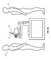
- FIG. 1Ais a pictorial front view of an exemplary dye sublimation transfer printing apparatus consistent with disclosed embodiments.
- FIG. 1Bis a front view of the dye sublimation transfer printing apparatus of FIG. 1A .
- FIG. 1Cis a side view of the dye sublimation transfer printing apparatus of FIG. 1A .
- FIG. 2Aillustrates the dye sublimation transfer printing apparatus of FIGS. 1A-1C with part of the exterior housing rendered transparently to show detail, with the lower platen of the apparatus in the product loading position, consistent with disclosed embodiments;
- FIG. 2Billustrates the dye sublimation transfer printing apparatus of FIGS. 1A-1C with part of the exterior housing rendered transparently to show detail, with the lower platen in the product sublimation position, consistent with disclosed embodiments;
- FIG. 2Cillustrates the dye sublimation transfer printing apparatus of FIGS. 1A-1C with part of the exterior housing rendered transparently to show detail, with the lower platen in the product cooling position, consistent with disclosed embodiments;
- FIG. 3is a pictorial cross-sectional view of FIG. 2B showing additional detail, consistent with disclosed embodiments;
- FIG. 4is a detailed profile cutaway view of a portion of the dye sublimation transfer printing apparatus of FIGS. 1A-1C , consistent with disclosed embodiments;
- FIGS. 5A-5Billustrate operator-facing and consumer-facing embodiments of the dye sublimation transfer printing apparatus of FIGS. 1A-1C , consistent with disclosed embodiments;
- FIG. 6is a top view of the lower platen of the dye sublimation transfer printing apparatus of FIGS. 1A-1C in the product loading position, consistent with disclosed embodiments;
- FIG. 7is a more detailed view of FIG. 6 , consistent with disclosed embodiments.
- FIG. 8is a flowchart of an exemplary dye sublimation transfer printer apparatus operation process, consistent with disclosed embodiments
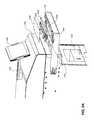
- FIG. 9Ais an exploded view of a cassette for streamlined alignment of a product within a sublimation apparatus, consistent with disclosed embodiments;
- FIG. 9Bis an exploded view of a cassette for streamlined alignment of a product within a sublimation apparatus, consistent with disclosed embodiments;
- FIG. 9Cis a pictorial view of a cassette for streamlined alignment of a product successfully aligned within a sublimation apparatus, consistent with disclosed embodiments;
- FIG. 10is a detailed view of a cassette for streamlined alignment of a product within a sublimation apparatus, consistent with disclosed embodiments;
- FIG. 11is an example user interface associated with a sublimation apparatus for attracting consumers to the apparatus, consistent with disclosed embodiments
- FIG. 12is an example user interface associated with a sublimation apparatus for facilitating controlled access to the apparatus by an operator, consistent with disclosed embodiments;
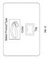
- FIG. 13is an example user interface associated with a sublimation apparatus for selecting one of a plurality of different types of products to be sublimated, consistent with disclosed embodiments;
- FIG. 14is an example user interface associated with a sublimation apparatus for customizing a product, consistent with disclosed embodiments
- FIG. 15is an example user interface associated with a sublimation apparatus for customizing a product, consistent with disclosed embodiments
- FIG. 16is an example user interface associated with a sublimation apparatus for customizing a product, consistent with disclosed embodiments
- FIG. 17is an example user interface associated with a sublimation apparatus for providing the operator and consumer with an estimated time remaining for a sublimation task, consistent with disclosed embodiments.
- FIG. 18is an example user interface associated with a sublimation apparatus for indicating that a sublimation task is complete, consistent with disclosed embodiments.
- FIGS. 1A-1Cillustrate an exemplary dye sublimation transfer printing apparatus 100 .
- Apparatus 100may contain various interchangeable modular fixtures configured to complete printing and sublimation tasks.
- moduleis not used in a manner requiring a completely separate modular arrangement. Rather, “module” is used more generally to refer to the components necessary to provide the required functionality. In effect, the noted modules are subsystems within the integrated apparatus. Depending upon the applications and requirements of a given consumer, the integrated apparatus can be customized to include only the desired subsystems. As such, FIGS. 1A-1C illustrate but one example of an apparatus within the scope of the invention.
- Apparatus 100may be configured in a variety of ways depending on the needs and applications of the user.
- Apparatus 100may be configured as a clerk-operated kiosk with an offboard inventory of products to be sublimated.
- a subset of the modules discussed abovemay be manual variations operable by an operator such as a clerk or employee of a retail establishment.
- a clerk-operated kioskmay be situated in a retail establishment in a location accessible to employees of the establishment, such as behind a counter or in a restricted area.
- apparatus 100may or may not have all components enclosed.
- apparatus 100may be configured as a consumer-operated kiosk with an offboard inventory of products to be sublimated.
- a subset of the automated modules discussed abovemay be substituted with manual variations operable by an untrained operator such as a consumer of a retail establishment.
- a consumer-operated kiosk with an offboard inventory of products to be sublimatedmay be situated in a retail establishment in a location potentially accessible both to consumers of the establishment and to employees of the establishment.
- apparatus 100may or may not have all components enclosed. The non-enclosed components may not be fully accessible to the consumer.
- apparatus 100may be configured as a hybrid kiosk with offboard inventory, with some modules configured to be operable by a clerk, and some configured to be operable by a consumer.
- the modular subsystem features of the apparatuspromote deployment of the apparatus in a variety of ways.
- the apparatusmay be suitable for customizable footprints to meet the needs of the hosting entity. For example, if the apparatus must fit in the corner of a room, the modular design may permit the device to wrap around the corner.
- a “countertop” configurationmight be a good fit for a jewelry counter at a department store.
- the subsystem configurationincreases the flexibility and versatility of the apparatus and increases the market possibilities for the invention.
- a single dye sublimation transfer printermay be associated with multiple sublimation apparatuses, such that multiple sublimation tasks may be ongoing simultaneously.
- Products for sublimationmay be comprised of various materials.
- the productsmay be comprised of plastic.
- the productsmay be comprised of metal, such as aluminum, brass, or steel.
- the productsmay be comprised of a ceramic material, a fabric or textile material, wood, fiberglass, or glass.
- the productregardless of its constituent material, may be additionally coated with a material to enhance integration and permanence of the sublimation dye, such as a polyester material. The added coating may be introduced to the surface of the product in various ways, such as spraying, dipping, painting, etc.
- Possible candidate products and accessories for use in apparatus 100may include, but are not limited to, luggage tags, pet tags, bookmarks, identification tags, dog tags, gift tags, ornaments, picture frames, picture frame inserts, cases for a mobile device, inserts for cases for a mobile device, various types of jewelry, such as pendants, bracelets, watch bands, earrings, necklaces, etc., fabrics, such as clothing, banners, draperies, etc., and any item that could integrate sublimation dye and bear a sublimated image.
- products for sublimation in apparatus 100are flat plates with opposing surfaces.
- the products for sublimationmay include keys, key heads, or key blades.
- productscould be flat, three-dimensional shapes, such as cubes.
- curved surfacesare possible.
- productssuch as coffee mugs, decorative glass products such as vases or barware, sports balls, and medical identification bracelets could be candidates for receiving sublimated images.
- Candidate products for sublimationmay be provided by the user, or they may be disposed within or proximal to the printing apparatus.
- the apparatusmay be configured as a vending apparatus and the products may be situated inside of the apparatus.
- the vending apparatusmay be capable of receiving a product inserted into the machine by a user.
- the apparatusmay be further configured to receive, sublimate, and/or dispense accessory items that match or accompany candidate products for sublimation.
- the accessoriesin a similar manner to the products, may be contained within the apparatus, proximal to the apparatus, or may be inserted into the apparatus by a user. Examples may include, but not be limited to, picture frames, luggage tag holders, bracelets, jewelry, key chains, necklaces, key rings, etc.
- the inserted accessorymay be a pre-packaged accessory designed to accompany the customized sublimated product.
- Housing 102may be configured to enclose some or all of the components of apparatus 100 in a manner that prevents an operator from contacting the enclosed components.
- Housing 102may be comprised of metal, plastic, glass, or a combination thereof.
- Housing 102may serve several important functions; it protects the operator (or others) from burn, pressure, pinch, or puncture injuries that could occur as a result of contact with the apparatus components. Further, housing 102 protects the apparatus itself, shielding the components from wear and tear and keeping them clear of dust, insects/animals, etc.
- Components involving heat or coldmay be disposed within housing 102 such that they do not touch any of the housing walls, so as to maintain the external surface of housing 102 at a temperature safe for touch.
- Housing 102may be configured to include one or more shells 104 .
- the materials comprising shell 104may include, as non-limiting examples, acrylic, glass, fiberglass, plastic, or a hybrid material.
- Shell 104may be oriented in a manner that makes the components of a dye sublimation printer apparatus, such as apparatus 100 , visible to a clerk, other operator, or consumer while safely shielding the user from heat, pinch points, stored energy sources, and other such potential hazards associated with the operation of heavy machinery.
- Shell 104may provide entertainment and education to the user while the sublimation task is underway, and may also allow an operator to take note of components of the apparatus requiring maintenance or repair.
- Shell 104may be disposed atop housing 102 , as shown in FIGS. 1A-1C . Alternatively, shell 104 may be disposed within or on a side of housing 102 .
- User interface device 106may be configured to assist a consumer in selecting and confirming one or more images to print on the transfer media, selecting one or more products on which to sublimate the printed images, and coordinating payment for the product.
- Device 106may include input and output components to enable information associated with the sublimation task to be provided to a user, and also for the user to input required information.
- the input componentsmay include a physical or virtual keyboard. For example, a consumer may first be prompted by device 106 to determine one or more images to be printed by an associated printer onto sheets of transfer media.
- device 106may be configured to contain a library of digital image files within an associated memory device, or in a memory device or database accessible over a network connection.
- user interface device 106may be configured to receive a digital image file in various additional ways, including but not limited to receiving insertion of flash memory or a USB drive, connecting via a USB or Firewire® cable, receiving image files by email, receiving image files uploaded via a mobile application, retrieving user-submitted image files from an online library or website, etc.
- user interface device 106may be configured to transmit or receive information from a mobile application associated with one or more of a manufacturer of the vending apparatus, a retailer hosting the vending apparatus, or a third party.
- apparatus 100 and the mobile applicationmay be configured to exchange information relating to the consumer and/or to a sublimation task associated with the user.
- the informationmay comprise one or more of information associated with a product the consumer wishes to sublimate, information associated with an image or text to be sublimated on the product, information associated with payment for the sublimated product, or information comprising a location of the nearest vending apparatus.
- apparatus 100may be configured to receive a fully pre-paid, pre-configured order for a sublimation task from the mobile application.
- apparatus 100may receive the order directly from the mobile application via user interface device 106 (for example, if a particular apparatus 100 is determined to be the closest geographically to the consumer).
- user interface device 106may be configured to access a remote server to retrieve information relating to the order from the mobile application.
- apparatus 100may be configured to receive a code configured to facilitate access by user interface device 106 to information associated with a saved transaction ordered from the mobile application.
- user interface device 106may be capable of outputting audible notifications or alerts to a consumer or operator of apparatus 100 .
- user interface device 106may be configured to tell the user to “LOOK AT THE SCREEN” when information is required from the user or important information is displayed for the user.
- device 106may be configured to audibly output “YOUR PRODUCT IS READY” when the sublimation process is complete and the product is cooled to a safe handling temperature.
- the audio output capabilities of apparatus 100may extend to the input components.
- User interface device 106may include one or more display screens, which may serve as both an input and output device.
- User interface device 106may be configured such that key presses on a virtual keyboard or touchscreen buttons associated with the one or more display screens elicit confirmatory clicking noises. Additionally, the input components of device 106 may be configured to provide tactile or visual feedback to the user to indicate that an input member, such as a key of a keyboard, has been successfully pressed.
- user interface device 106may permit the consumer to select from a plurality of possible stock images to incorporate personal information in textual form.
- device 106may be configured to, at the selection of the consumer, synthesize the personal information into a selected stock image from the device memory, and provide the single synthesized image to the included printer for printing onto transfer media. This process is described in further detail below in association with FIGS. 8 and 13-18 .
- Device 106may be configured to store the received personal information as well as any personalized, synthesized, or stock images created or selected by the consumer. Further, device 106 may be configured to prompt the consumer for additional products that they may desire to have sublimated with the same image.
- user interface device 106may be configured to transmit the stored consumer image to a remote network server, and may communicate an indication to the consumer regarding information about additional sublimated or customized products that might be available for the consumer that can be printed and shipped from a remote location.
- the indicationmay be communicated to the consumer through various known means of communication, such as by telephone, email, social media, or on an internet webpage associated with one or more of the consumer, the retail outlet hosting apparatus 100 , or the maker of apparatus 100 .
- user interface device 106may provide further options to the user, including customizing and purchasing accessories for the sublimated product, or configuring a delivery vehicle for the product.
- User interface device 106may also be configured to prompt the user to select a companion accessory for the sublimated product.
- the accessoryalso may be capable of sublimation by the apparatus.
- Device 106may be configured to coordinate and collect payment for the accessory.
- apparatus 100may be configured to utilize the used transfer media as a delivery vehicle for the sublimated product.
- the transfer mediamay be preprinted on one or more sides with text or images associated with the retail outlet hosting apparatus 100 , or the manufacturer of apparatus 100 .
- apparatus 100may be configured as a direct printing system.
- no sheet of transfer mediais used, and apparatus 100 and an associated printer may be configured to sublimate images directly onto products.
- these productsregardless of their constituent material, may be additionally coated with a material to enhance integration and permanence of the sublimation dye, such as a polyester material.
- the added coatingmay be introduced to the surface of the product in various ways, such as spraying, dipping, painting, etc.
- the productsmay be configured in the factory to bear these coatings, or the coating may be added at a retail establishment in order to sublimate the product within a direct sublimation system.
- a printer associated with apparatus 100may be configured to print the images directly onto products, via inkjet, laser jet, or other technologies known in the printing arts.
- Heat, pressure, and duration of the direct sublimation processmay be configured for each product by user interface device 106 in the same manner as described for a transfer sublimation system.
- user interface device 106may be further configured to coordinate and collect payment for a sublimation task.
- a memory associated with user interface device 106may contain information relating to pricing for various types of products. The pricing may vary by product, and may vary based on other predetermined criteria, such as the quantity of objects desired, image processing tasks completed, images acquired via an associated camera, etc.
- User interface device 106may display the pricing information on an output screen to the user via a graphical user interface.
- device 106may include, or be connected to, payment acceptance components that can accept cash, credit cards, or other payment methods from the consumer, such as a coupon, or a payment application on a mobile device.
- user interface device 106may include an associated printer that can provide the consumer with a payment ticket containing information regarding the payment transaction. The consumer may then carry the payment ticket to a cashier for payment.
- the associated printermay be the same printer used for printing images on transfer media, or it may be a different, dedicated printer.
- the payment ticketmay also serve as a receipt, and may also contain other information, such as an Internet URL for a website associated with either the retail outlet hosting apparatus 100 , or the manufacturer of apparatus 100 for purposes of marketing additional possible products. It should be understood that a device similar to user interface device 106 , with any of the above configurations, may be provided as part of any apparatus consistent with disclosed embodiments.
- User interface device 106may be coupled to housing 102 via screen mount 108 .
- Screen mount 108helps keep user interface device 106 away from any heat or moisture associated with the operations of apparatus 100 .
- screen mount 108may be configured to be rotatable in the X, Y, or Z planes. In the example illustrated in FIGS. 1A-1C , screen mount 108 is rotatable in the Y axis, enabling the attached user interface device 106 to be “flipped” in orientation from top to bottom around a fulcrum associated with screen mount 108 .
- the information displayed on user interface device 106may be configured to move along with device 106 as it translates via screen mount 108 . For example, the orientation of the information may rotate 90 or 180 degrees as needed so that it can be viewed and read normally in any position of user interface device 106 and screen mount 108 . This process is described in further detail in association with FIGS. 5A-5B below.
- components of the sublimation machinerymay be disposed within shell 104 , such as press assembly 110 .
- Press assembly 110which will be discussed in further detail below in association with FIGS. 3 and 4 , may comprise various mechanical components assembled for the purpose of providing heat and pressure for a sublimation process.
- press assembly 110may be disposed atop housing 102 .
- press assembly 110may be disposed within housing 102 .
- press assembly 110may be disposed such that a portion of the assembly is outside of housing 102 and a portion is inside of housing 102 .
- Press assembly 110may be configured as a spring-loaded system.
- springs 112may be disposed as part of press assembly 110 .
- components of press assembly 110such as springs 112 may be configured to monitor and manage the pressure and force applied to a product during a sublimation task.
- springs 112are springs that have a high spring constant. The purpose of springs 112 is to provide compliance and sensitivity to the pressing operation, to enable apparatus 100 to sublimate many products of different sizes, shapes, and composition.
- apparatus 100may include a cooling system 114 .
- the cooling systemmay be configured to cool the sublimated product to at least about an ambient temperature. The cooling process provides safety for handlers of the sublimated object, and also helps ensure the quality and permanence of the sublimation transfer by preventing smearing, blistering, etc.
- cooling system 114is a fan that cools the hot sublimated product.
- lower platen 118may be automatically translated by components of apparatus 100 from a sublimation position in alignment with press assembly 110 and associated heating platens to a position in alignment with cooling system 114 . After a predetermined cooling period (which may be unique for every product and/or the complexity of every sublimated image), apparatus 100 may eject lower platen 118 and the cooled product may be presented to the consumer by the apparatus operator.
- housing 102may be equipped with a ventilation system.
- the ventilation systemis represented by shell vents 116 .
- the ventilation systemmay result in ambient air flowing into the machine, either by natural convection or by forced convection, such as through a series of fans.
- the ventilation systemmay be further configured to interface with a larger ventilation system for the retail establishment or other structure hosting the apparatus.
- a ventilation systemmay permit heating platens associated with press assembly 110 to be kept at a steady state intermediate temperature or even at full operational temperature, without creating burn risks to users or excessively raising the ambient temperature of the surrounding air.
- the ventilation systemmay be configured to control a temperature within housing 102 such that the mechanical and electrical components of apparatus 100 are protected from damage and the exterior surface of housing 102 and transparent shell 104 remain touch-safe (e.g., at a temperature that will not harm an individual when that individual's skin contacts the surface). Allowing the enclosed components, including the heating platens, to remain at an intermediate but safe temperature reduces system warm-up time and consumer wait time.
- Lower platen 118is a substantially flat platen configured to receive the product to be sublimated and the transfer media and align and register them to prepare for the sublimation process.
- lower platen 118may be configured in the form of a “drawer” that translates inside and outside of housing 102 . This configuration will be described in further detail in association with FIGS. 2A-2C .
- lower platen 118may be a bare platen comprised of a metal, such as steel or aluminum, in order to provide structural support along with optimal heat conductivity properties.
- lower platen 118may be comprised of plastic, or a composite product.
- lower platen 118may be configured to provide additional heat to the sublimation process.
- Lower platen 118may include components that assist in positioning and securing the transfer media to ensure faithful transfer of the printed image to a desired product.
- lower platen 118may include features, such as contact or non-contact sensors, to assist with the registration and alignment of the transfer media and/or the products that will receive the sublimated image. Further detail of these features is described below and illustrated in FIGS. 6 and 7 .
- Apparatus 100may interface with a printer for printing images onto transfer media.
- the printermay be disposed within housing 102 , and accessed via printer access opening 120 .
- Printer 122is illustrated in FIGS. 1B and 1C , with printer access opening 120 visible in FIGS. 1A and 1B .
- printer 122may be electronically configured to receive a file representing a digital image from an operator or a consumer.
- the digital image filemay represent images such as pictures, text, stylized text, or a combination of these elements.
- printer 122may receive the digital image file directly, and may include digital media input interface components.
- the printermay be linked via a physical or a network connection to a distinct interface device or module (such as user interface device 106 ) which is configured to permit a user to determine a digital image file for printing.
- printer 122may be configured to receive a file representing a digital image selected at the point of sale by a user from a library or database containing a plurality of preloaded stock image files.
- a library or databasemay be stored in a memory associated with user interface device 106 , or may be accessible via a network connection.
- apparatus 100may be capable of receiving input in the form of text from a user, and may convert or incorporate the text into a printable digital image file for sublimation.
- Printer 122may be configured to utilize standard sublimation dyes known in the art to print the received digital image file onto suitable transfer media.
- the transfer mediamay comprise any material capable of receiving a printed dye image, including but not limited to coated or uncoated paper, card stock, film, resin, wax, ribbon, tape, etc.
- printer 122is configured to print images onto individual sheets of transfer media.
- printer 122may include or be connected to a bulk storage unit containing a plurality of sheets of transfer media.
- individual sheets of the transfer mediamay be fed into printer 122 one sheet at a time by an operator.
- printer 122may be configured to automatically feed the sheets of transfer media into proximity with the print head and sublimation dyes for printing.
- printer 122may be configured as a manual, hand-fed printer in which an operator may introduce each sheet of transfer media into the printer.
- Some embodiments of apparatus 100may be configured for both manual and automatic sheet feeding.
- Printer 122may be configured to print a dye image on one side of each sheet of the transfer media, or alternatively may be capable of printing dye images on both sides of each sheet.
- Printer 122may be configured to print the images in a single pass, or may require two passes, such as for complex images, multiple colors, or multiple layers of images.
- a printed dye imagemay include multiple distinct images superimposed into a single image. The printer may print the superimposed image in a single pass, or may print each constituent image in its own pass through the machine.
- apparatus 100may be configured to simply allow an operator to place and transport the printed transfer media by hand to other parts of the system.
- printer 122may be disposed in a manner such that it is separate from the rest of the components of apparatus 100 and not enclosed within housing 102 .
- apparatus 100 and printer 122may not be physically co-located.
- an operatormay feed the sheet or sheets of transfer media into printer 122 for printing, and then manually place the transfer media, now containing the printed images, into the other components of apparatus 100 .
- apparatus 100may sublimate the printed images on the transfer media to selected products using heating platen 124 .
- Apparatus 100may contain one or more heating platens. In the embodiment illustrated in FIGS. 1A-1C , apparatus 100 contains a single heating platen 124 . However, in alternative embodiments, more than one heating platen may be employed in apparatus 100 , and lower platen 118 may be configured to include a second heating platen.
- Heating platen 124may be comprised of any heat-conductive material, such as metal or ceramic.
- heating platen 124is comprised of cast iron, aluminum, or zinc.
- Heating platen 124may be surrounded by an additional heat shield (not shown), which may be comprised of a material that insulates the system and reduces heat transfer to the exterior surfaces and surrounding elements of apparatus 100 .
- the heat shieldmay be comprised of metal, plastic, ceramic, rubber, or any other suitable material.
- Heating platen 124may additionally be coated with a compliant material.
- a compliant materialmay comprise a foam, rubber, or plastic possessing the ability to maintain structural integrity under high temperatures and pressures.
- the compliant nature of the platen coatingassists in the application of an even heat and pressure across all surfaces to be sublimated. Maintaining consistency of heat and pressure results in higher quality sublimated products, and reduces the risk of damage to either the product or the platen.
- lower platen 118may be similarly coated with such a compliant material.
- heating platen 124itself may have inherent flexibility, and may be capable of deformation across a product during sublimation to ensure even application of heat and pressure.
- apparatus 100may be configured to bring heating platen 124 and the transfer media as situated on lower platen 118 into contact in order to sublimate printed images onto a product. It is to be understood that various configurations of heating platen 124 , lower platen 118 , and other components of apparatus 100 are possible, and that all such configurations are contemplated by the claims.
- heating platen 124may be moved into contact with lower platen 118 and the transfer media (which remain stationary) by apparatus 100 via press assembly 110 .
- lower platen 118may be moved into contact with heating platen 124 (which remains stationary).
- both heating platen 124 and lower platen 118may be moved.
- Product platen 126may be configured to mechanically interface with lower platen 118 .
- the purpose of product platen 126is to enable apparatus 100 to sublimate a wide variety of different products with high-quality images.
- Product platen 126will be illustrated and described in detail in association with FIG. 6 , but in brief, product platen 126 may be configured in a manner that allows multiple types of products to be aligned and secured for sublimation. Rather than a “one size fits all” approach, the customizable configuration of product platen 126 provides additional versatility and flexibility to apparatus 100 .
- product platen 126may be configured to accept one or more different types of pet-related products.
- product platen 126may be deployed in a cruciform shape.
- product platen 126could accept long, narrow products for sublimation such as collars and leashes.
- product platen 126could accept more compact products, such as pet tags, luggage tags, plaques for pet bowls, etc.
- Product platen 126may be configured in whatever manner is necessary to accept particular products, and may be configured with various lengths, widths, and depths. In some embodiments, multiple product platens 126 may be available for a given apparatus 100 and lower platen 118 , and an operator may be able to switch out the various product platens 126 based on the details of a particular sublimation task.
- Product platen 126may be made out of aluminum, for light weight and structural integrity, but in other embodiments may be made from other metals, plastics, or composites.
- heating platen 124may be operated by apparatus 100 in a single thermal cycle to sublimate the printed images from the transfer media onto the product.
- the single thermal cycle of heating platen 124may be configured with a temperature, pressure, and duration sufficient to successfully transfer the image(s) to the selected product. These operations are controlled and coordinated by thermal management unit 128 , motor 130 , heater controller 132 , and motion controller 134 .
- the duration of the thermal cyclemeasured as the dwell time of the platen on the transfer media, may vary based on the product to be sublimated, the transfer media, and the heating temperature of heating platen 124 .
- heating platen 4is maintained by heater controller 132 and thermal management unit 128 at a temperature of about 400 degrees Fahrenheit for the entirety of the time that it is in contact with the transfer media.
- the pressure of the thermal cyclemay be about 30 to 40 psi, but may vary based on, for example, the composition of the product or the complexity and color scheme of the image to be sublimated.
- the temperature, duration, and pressure of a heating platen 124 single thermal cyclemay be determined based on a variety of predetermined criteria.
- the predetermined criteriamay include properties of the product being sublimated, including but not limited to dimensions of the product, the material comprising the product, the product's shape or curvature, etc.
- the productmay be configured in a manner that presents this information to apparatus 100 and to heater controller 132 and motion controller 134 .
- individual productsmay be marked with a barcode, a QR code, or other such indicia that may be scannable or otherwise readable by apparatus 100 .
- This indiciamay contain information such as that described above that is unique to each product and provides guidance as to the parameters needed to configure the thermal cycle for apparatus 100 .
- user interface device 106may be periodically programmed to contain this information for all available products associated with a particular apparatus 100 , and user interface device 106 may be configured to transmit this information to heater controller 132 and motion controller 134 .
- the predetermined criteria informing the configuration of the thermal cyclemay include characteristics of the printed images, including but not limited to pixel intensity or density of the printed image, colors utilized in the image, size of the image, etc.
- heating platen 124may be configured to provide differential heating based on the predetermined criteria; for example, one or more regions on heating platen 124 may be heated to a different temperature than one or more other regions on the platen. The differential heating may correspond with one or more regions of product platen 126 that support the product. In these embodiments, apparatus 100 may provide an energy savings by heating only the regions of heating platen 124 that are needed for a particular product.
- the differential heatingmay comprise one or more regions on heating platen 124 that transmit heat for a different duration of time than one or more other regions on the platen.
- Different pressuresmay also be utilized. Pressure as used herein may refer to a programmed force configured by the control and exerted as a pressing force by heating platen 124 and press assembly 110 , or it may relate to a position in three dimensional space achieved by heating platen 124 during the thermal cycle.
- the duration of the cyclemay be altered depending on the thickness or material composition of the product.
- the programmed durationmust account for thermal resistance within the material comprising the product, and must ensure that all surfaces of the product are exposed to a proper sublimation temperature of, for example, 350 degrees Fahrenheit without overheating, warping, or otherwise damaging the platen, the product, or the transfer media.
- a thin, polyester pet collarmay have different thermal cycle parameters than a metal dog tag or a thick porcelain dog bowl.
- the single thermal cycle of heating platen 124may be further governed by external factors, such as conditions within the establishment hosting apparatus 100 . It is desirable that apparatus 100 be capable of operating within a conventional electrical power configuration, utilizing either a standard 120 volt plug or a dedicated 240 volt plug, such as that used in larger household appliances. Apparatus 100 must be capable of heating relatively quickly without exceeding or draining the power capacity of its host establishment. Therefore, in some embodiments where available power is limited, apparatus 100 and heating platen 124 may be configured in the control software of heater controller 132 and thermal management unit 128 with alternate automated warm-up and cool-down cycles to permit successful sublimation within an existing electrical configuration. In these embodiments, apparatus 100 may be flexibly reconfigured via the control software to integrate into various deployment environments without the need to replace, alter, or custom design hardware components.
- lower platen 118may be configured to translate in and out of housing 102 .
- lower platen 118may be disposed on a linear motion stage (not shown), and its motion may be controlled by motor 130 and motion controller 134 .
- motor 130 and motion controller 134Whether apparatus 100 is deployed as a clerk-operated kiosk, or as an automated system, safety and efficiency are essential in a sublimation system.
- the placement of lower platen 118 on a linear motion stageallows increased accessibility to the platen by an operator or by components of an automated system. More detail about this system is described below in association with FIGS. 2A-2C .
- the linear distance traveled by one or both of lower platen 118 and/or heating platen 124may be monitored and programmed as part of the single thermal cycle in lieu of or in addition to the pressure provided by press assembly 110 .
- This monitoringmay be performed, for example, by motion controller 134 .
- linear distancemay be measured based on the compression force experienced by springs 112 of press assembly 110 , which will have a known spring constant permitting accurate force and distance calculations.
- a linear potentiometer, linear variable differential transformer (LVDT), or other linear measuring sensor associated with motion controller 134may be utilized to monitor and control the press distance.
- Linear distancesmay be important for avoiding breakage of a sublimated product and/or damage to the components of apparatus 100 . Such a measurement could be particularly useful in the sublimation of fragile, three-dimensional objects such as ornaments or jewelry.
- Linear distancemay be measured in alternative embodiments as the distance between heating platen 124 and lower platen 118 . This linear distance may be preset for particular products based on their known dimensions, and may be included in the product-specific information described above. This information may also be integrated into readable indicia on the products themselves, or again pre-programmed into a memory or database associated with user interface device 106 . In these embodiments, one or both of lower platen 118 or heating platen 124 may be pre-configured (e.g.
- motion controller 134 and heater controller 132may operate in concert to automatically configure these parameters for the heating platen 124 and lower platen 118 for a particular sublimation task.
- FIGS. 2A-2Cillustrate different stages of a typical sublimation task for apparatus 100 as controlled by heater controller 132 and motion controller 134 .
- lower platen 118may be conveyed to various pre-configured “stop” positions within and outside of housing 102 by motor 130 and motion controller 134 . These positions may be a pre-defined distance away from other elements of apparatus 100 associated with heat and pressure.
- the stop positionsmay be registered in a coordinate system or other such localization system, and may enable motion controller 134 to return lower platen 118 to a proper initial position before and/or after each sublimation cycle.
- apparatus 100In certain clerk-operated embodiments of apparatus 100 , the operator can place and align the product and the transfer media without worry of danger from other system elements. This stage of the process is illustrated in FIG. 2A .
- motor 130 and motion controller 134have ejected lower platen 118 from inside of housing 102 to a position outside of housing 102 where lower platen 118 and product platen 126 are readily accessible.
- Apparatus 100may reach the configuration at two different points during a typical sublimation task: at the beginning of the task, when the product and printed transfer media are loaded onto product platen 126 , and at the end of the task, when the transfer media is removed by the operator and the cooled, sublimated product is removed and provided to the consumer.
- apparatus 100may be configured as shown in FIG. 2A at all times. In other embodiments, apparatus 100 may be configured in a manner where lower platen 118 is secured within housing 102 when not in use in order to prevent unauthorized access to the system. Motor 130 and motion controller 134 may be configured to “pop out” lower platen 118 in response to various stimuli. In some embodiments, motor 130 and motion controller 134 may cause lower platen 118 to emerge from housing 102 in response to an operator providing proper security credentials to apparatus 100 via user interface device 106 .
- motor 130 and motion controller 134may cause lower platen 118 to emerge from housing 102 in response to a tactile stimulus, such as an operator pressing inward on the outward-facing “drawer” surface of lower platen 118 .
- motor 130 and motion controller 134may cause lower platen 118 to emerge based on another stimulus, such as pressing of a button or unlocking of a lock.
- lower platen 118may be translated by motor 130 and motion controller 134 to a position aligned in the X and Y directions with heating platen 124 . This configuration is illustrated in FIG. 2B . In some embodiments, this position aligned with heating platen 124 may also be pre-programmed into motion controller 134 , such that lower platen 118 is reliably moved to the correct position at the beginning of each sublimation task.
- apparatus 100brings lower platen 118 and heating platen 124 into contact via press assembly 110 and motion controller 134 .
- the heated platen surface of heating platen 124is engaged with the transfer media laid atop the product secured in product platen 126 .
- Apparatus 100may remain in the configuration shown in FIG. 2B for a pre-determined amount of “dwell time” based on properties of the product, or properties of the printed image(s). Instructions to this end may be processed by one or more of user interface device 106 and associated processors, by heater controller 132 , and/or motion controller 134 .
- FIG. 2Cillustrates a third stage of a sublimation task.
- motor 130 and motion controller 134may translate lower platen 118 to an intermediate stop position between the initial position and the sublimation position.
- product platen 126is aligned in the X and Y directions with cooling system 114 , and the sublimated product may be actively cooled by the cooling system.
- apparatus 100may de-energize heating platen 124 via heater controller 132 , either completely or to an intermediate holding temperature as discussed above.
- motor 130 and motion controller 134may translate lower platen 118 back to the initial position shown in FIG. 2A , and the operator may remove the cooled, sublimated product and provide it to the consumer.
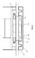
- FIG. 3is a pictorial cross-sectional view of the illustration of apparatus 100 described above in association with FIG. 2B .
- apparatus 100is in the middle of a sublimation task.
- the cross-sectional view of FIG. 3provides more details on other components of apparatus 100 .
- reference labels 302 , 304 , 306 , and 308refer to components of the screw-driven, lever-action press assembly 110 that are not otherwise visible.
- Guided spring plate assembly 302provides an interface between components of press assembly 110 and heating platen 124 via springs 112 . Assembly 302 transfers force exerted by other components of press assembly 110 to heating platen 124 via springs 112 .
- Fulcrum plate 304is a pivotable lever arm connecting guided spring plate assembly 302 to the components of press assembly 110 that produce and provide force: motor 306 and drive screw 308 .
- motor 306via motion controller 134 ) provides propulsive force upward in the Z-direction
- drive screw 308translates upward. This movement in turn exerts force onto one end of fulcrum plate 304 , which results in an eventual transfer of the force to the opposite end.
- fulcrum plate 304works as a lever arm, or a children's see-saw.
- the force from motor 306is then driven downward through guided spring plate assembly 302 and into heating platen 124 to produce the 30-40 psi needed to properly sublimate the printed image from the transfer media to the product. This may amount to 300-400 lbs of equivalent downward force. Accordingly, lower platen 118 and product platen 126 must be manufactured in a manner and of a material capable of withstanding these forces.
- Motor 306may be configured to reverse its motion.
- motor 312may be capable of retracting drive screw 308 to reverse the force transduction through press assembly 110 and separate heating platen 124 and lower platen 118 .
- FIG. 3also provides a cross-sectional view of motor 130 , illustrating horizontally-oriented drive screw 312 .
- motor 130propels drive screw 312 to translate the position of lower platen 118 .
- this motionmay include translating lower platen 118 on and off of a “ramp”-like structure, particularly when lower platen 118 is in the “sublimation position” illustrated in FIG. 2B and FIG. 3 .
- This “ramp”(not shown in FIG. 3 ) may provide additional structural stability to lower platen 118 so it can withstand the pressure exerted by press assembly 110 .
- motor 130may be configured to reverse its motion upon a signal transmitted by motion controller 134 . This reversible motion enables the bidirectional translation of lower platen 118 . Also included along the “track” of lower platen 118 are various safety interlock features 314 , which may prevent lower platen 118 from being translated by motor 130 and drive screw 312 past a certain point in the Y direction. These safety features prevent damage to apparatus 100 and provide additional safety for an operator and/or a consumer.
- FIG. 4provides a different perspective view of the components described above in association with FIG. 3 , particularly elements 302 - 308 of press assembly 110 .
- This perspectiveillustrates how the force generated by motor 306 may be transferred through press assembly 110 and applied to heating platen 124 so it may sublimate a product (not shown) secured in product platen 126 .
- FIGS. 5A and 5Billustrate typical operation of apparatus 100 by an operator 502 and a consumer 504 .
- operator 502may be a clerk, associate, employee, etc. of a retail establishment hosting apparatus 100 .
- operator 502may be an employee of the entity that manufactures apparatus 100 .
- operator 502may be an independent contractor or an employee employed by a third entity unaffiliated with either the previously-described host entity or manufacturing entity.
- Consumer 504may represent a customer of a retail establishment interested in purchasing a personalized sublimated product.
- apparatus 100is configured in a manner where user interface device 106 has been rotated on screen mount 108 such that the screen of user interface device 106 is visible and operable by consumer 504 .
- Apparatus 100may be configured in this alignment when input or decisions are required of consumer 504 , such as during selection of a product, selection of a design to be sublimated onto the product, entry of additional textual information such as names, addresses, etc., confirmation, and/or payment.
- apparatus 100is configured in a manner where user interface device 106 has been rotated on screen mount 108 such that the screen of user interface device 106 is visible and operable by operator 502 .
- Apparatus 100may be configured in this alignment when input or decisions are required of operator 502 , such as during initial apparatus access, during product loading (into product platen 126 ), and during the sublimation and cooling tasks.
- FIGS. 6 and 7illustrate additional detail of lower platen 118 , product platen 126 , and the alignment and securing of a product and the printed transfer media.
- a product 630here, a pet leash
- a sheet of transfer media 632has been overlaid on top of product 630 within product platen 126 , and is clamped to product platen 126 via transfer media clamps 634 .
- product 630may be laid on top of transfer media 632 .
- Product 630is itself clamped to product platen 126 via clamps 636 .
- Clamps 634 and 636may be spring-loaded, or may be clamped and secured via thumb screws or some sort of other reversible system.
- product 630is situated within a dedicated channel of product platen 126 configured to precisely fit that type of product.
- the rectangular channel of product platen 126 in the center portion of the platenis unused in this illustration, but could be utilized in a different sublimation task to sublimate tags, plaques, etc. as described above.
- the transfer media 632may contain one or more printed indicia and/or fiducial markers 638 .
- Proper alignment of product 630 and the transfer media 632 in a sublimation printing apparatus such as apparatus 100 described aboveis particularly important. Even a slight misplacement of the product 630 or the transfer media 632 may result in poor quality of the sublimated image and thus a defective sublimated product that wastes time and money for the retail establishment.
- Proper alignment of the transfer media 632 in a sublimation printing apparatus such as apparatus 100is particularly important when the apparatus is configured to print on more than one side of a product 630 substantially simultaneously.
- Proper alignment of the product 630 and transfer media 632may also be important to prevent hazards, such as overheating of the transfer media 632 . Even slight overheating of transfer media 632 may create unpleasant odors that could irritate the operator 502 and other surrounding consumers, such as consumer 504 .
- alignment of the product 630 and the transfer media 632 within product platen 126 and lower platen 118may be additionally facilitated by lights 640 .
- Lights 640may be disposed on or in product platen 126 , lower platen 118 , or both.
- FIG. 7Further detail of the interplay between fiducial markers 638 and lights 640 is shown in FIG. 7 .
- One or more lights 640may be configured to illuminate when lower platen 118 is translated to the “initial” loading position illustrated in FIG. 2A .
- lights 640may be illuminated at all times that apparatus 100 is operational. When lights 640 are illuminated, they permit operator 502 to place fiducial markers 638 printed on transfer media 632 wholly within the circumference of light 640 , ensuring proper alignment.
- Lights 640are disposed on product platen 126 /lower platen 118 at precise positions to ensure alignment with product.
- a particular apparatus 100may be configured with multiple sets of lights 640 to facilitate different spatial arrangements on product platen 126 for different products 630 and transfer media 632 .
- apparatus 100may have only a single set of lights 640 .
- fiducial markers 638may be printed onto transfer media 632 by printer 122 , and their locations on transfer media 632 may be variable for each printing task based on the printed image and based on the dimensions of the product 630 to be sublimated.
- the sheets of transfer media 632may be pre-printed at the factory with fiducial markers 638 .
- Apparatus 100may be configured to perform a sublimation process 800 , such as that shown in the example of FIG. 8 .
- a printer associated with apparatus 100such as printer 122
- the image(s)may be a consumer-provided image received through user interface device 106 .
- the image(s)may be stock images preloaded into the memory of user interface device 106 .
- the image(s)may constitute text input received by device 106 .
- the image(s)may be captured by a camera associated with device 106 .
- apparatus 100may be configured to begin other sublimation operations in conjunction with the printing of the transfer media. For example, heater controller 132 and thermal management unit 128 may begin heating of heating platen 124 to a proper sublimation temperature for the particular product 630 that has been selected by consumer 504 once printer 122 begins printing the selected images onto transfer media 632 .
- apparatus 100may receive the selected product 630 into the proper channel of product platen 126 by manual placement from operator 502 .
- operator 502may introduce a detachable product platen 126 specially configured to be associated with the selected product 630 , or a separate dedicated modular fixture as described above into lower platen 118 (Step 810 ).
- a separate modular fixturemay be used for certain types of product 630 , such as three-dimensional products. Using these fixtures, irregularly-shaped items such as coffee mugs, pet food bowls, Christmas ornaments, or other such items may be successfully sublimated within apparatus 100 .
- Apparatus 100may next assist with the placement and alignment of the printed transfer media 632 onto product platen 126 using the system components described above in association with FIGS. 6 and 7 , including lights 640 (Step 815 ). By assisting with the alignment of the fiducial markers 638 of transfer media 632 with lights 640 , the selected product 630 may be properly aligned with the images for sublimation printed on the transfer media 632 . Once aligned using the backlit system, apparatus 100 may receive the transfer media 632 by activation of clamps 634 (Step 820 ). In some embodiments, one or more of the processors or controllers described above may be configured to sense that clamps 634 have been activated.
- lower platen 118may be withdrawn into apparatus 100 (Step 825 ).
- lower platen 118may be withdrawn with the assistance of an operator 502 , via a tactile pressing motion.
- a button presseither on a virtual keyboard displayed on user interface device 106 or an actual physical button disposed on lower platen 118 or housing 102 may initiate the withdrawal process.
- apparatus 100may be configured to sense that all components are aligned and ready for sublimation, and may automatically withdraw lower platen 118 .
- apparatus 100may translate lower platen 118 into the proper “sublimation position” along its track (see FIG. 2B ) via motor 130 and motion controller 134 as described above.
- heater controller 132 and thermal management unit 128may configure the single thermal cycle for heating platen 124 using specific product information for product 630 as discussed above.
- Heater controller 132 and thermal management unit 128may receive the specific product information in various ways, such as by scanning of an indicia on product 630 , or by accessing a stored “profile” for the product 630 containing the information via user interface device 106 .
- Heater controller 132may process the software instructions associated with the specific product information and may use the instructions to configure the thermal cycle. Based on the thickness, dimensions, and material composition of product 630 (or other factors, as needed), heater controller 132 (and/or motion controller 134 , as needed) may determine the particular temperature, pressure, and dwell time needed to successfully complete the sublimation task.
- process 800continues with motion controller 134 and press assembly 110 engaging heating platen 124 and lower platen 118 (Step 840 ). Once contact is made, the thermal cycle is executed with the previously configured temperature, pressure, and dwell time, thus sublimating the one or more printed images of transfer media 632 onto one or more sides of the product 630 .
- apparatus 100may translate lower platen 118 back to its intermediate “cooling position” (see FIG. 2C ) (Step 845 ).
- apparatus 100may cool the sublimated product 630 to at least about an ambient temperature.
- apparatus 100via motion controller 134 and safety interlocks 316 , may be configured to limit access to the sublimated product 630 until the product has sufficiently cooled.
- the cooling time requiredmay vary by type of product 630 used, and this cooling time may be included within the specific product information introduced into apparatus 100 .
- apparatus 100via motor 130 and motion controller 134 , may translate lower platen 118 back to its initial position (see FIG. 2A ) (Step 850 ).
- lower platen 118 and product platen 126are again accessible by operator 502 , and operator 502 may remove the sublimated product 630 and provide it to consumer 504 .
- user interface device 106may facilitate and receive payment for the product 630 , or may alternatively provide consumer 504 with a printed ticket or receipt to facilitate payment at another location.
- apparatus 100may be alternatively configured such that product 630 is provided to apparatus 100 within a cassette, which may enable even more accurate and reliable alignment of the product.
- product 630may be affixed to or installed within the cassette at the factory.
- the cassettemay be reusable, and product 630 may be installed within the cassette by a clerk or a consumer at the time of customization.
- the transfer mediamay be included within the cassette, or may be added later. The use of a cassette may enable either a clerk or a consumer to operate apparatus 100 safely and effectively.
- FIGS. 9A-9Cillustrate a cassette-equipped embodiment of apparatus 100 .
- FIG. 9Ashows an apparatus 100 similar to that illustrated above in association with FIGS. 1A-7 , but configured to accept a cassette within lower platen 118 and/or product platen 126 .
- lower platen 118is in its “open” position to accept a product for sublimation, similar to the view of apparatus 100 illustrated in FIG. 2A .
- An exploded view of a cassette 902is shown.
- Cassette 902comprises a pre-affixed product 630 , as well as alignment implements 904 .
- a sheet of transfer media 632is also shown, with pre-punched holes that align with alignment implements 904 .
- transfer media 632may not be included or otherwise associated with cassette 902 .
- product platen 126includes a cassette interface 906 , which receives cassette 902 in a pre-aligned position for sublimation.
- the apparatus 100 shown in FIG. 9Atherefore may not be equipped with lights 640 , since the use of cassette 902 and cassette interface 906 streamlines the alignment process.
- the use of cassette 902 and cassette interface 906may be useful, for example, in consumer-operated embodiments of apparatus 100 where a clerk or other operator (such as operator 502 ) is not present to run the machine. Consumer 504 thus may be enabled to conduct a full sublimation task themselves without outside assistance.
- FIG. 9Billustrates the same apparatus 100 as FIG. 9A , but with cassette 902 coupled to cassette interface 906 (not visible in FIG. 9B ).
- apparatus 100may provide feedback to the operator (either operator 502 or consumer 504 ) indicating that cassette 902 is properly associated with cassette interface 906 .
- a tactile or visible mechanical responsemay be provided, such as a click, a button, a flag, or a tab indicating that cassette 902 is properly situated.
- user interface device 106may be configured to provide audio and/or visual feedback to the operator indicating that cassette 902 is properly associated with cassette interface 906 , or the opposite.
- FIG. 9Cis a detailed view of the entire cassette 902 and transfer media 632 situated within product platen 126 .
- Transfer media 632(printed with images to be sublimated on its opposing face (not shown)) is aligned on top of alignment implements 904 of cassette 902 .
- Alignment implements 904are illustrated as pegs in FIGS. 9A-9C , but may be any other type of mechanical implement that facilitates alignment of the transfer media. In embodiments where apparatus 100 is a direct sublimation apparatus, alignment implements 904 may be absent, since no transfer media 632 is required.
- lower platen 118is now ready to be withdrawn into apparatus 100 for the sublimation task, such as shown in FIG. 2B .
- apparatus 100may indicate to apparatus 100 that the task is ready to proceed via input into user interface 106 .
- apparatus 100may be configured to automatically sense either that cassette 902 is properly situated within product platen 126 , that transfer media 632 is properly aligned within cassette 902 , or both.
- apparatus 100may be configured to prompt the operator to perform actions via user interface device 106 .
- Apparatus 100may be further configured to automatically withdraw lower platen 118 when it senses that cassette 902 and (where present) transfer media 632 are properly situated and aligned.
- FIG. 10is a detailed view of cassette 902 .
- product 630is a pet collar or lead, and is affixed to cassette 902 at its ends.
- cassette 902may be configured for a single use, and may be associated with product 630 at the factory.
- cassette 902may be printed or otherwise associated with an indicia, such as a barcode, which will permit the item to be purchased and paid for prior to initiating the sublimation task.
- the indiciamay be printed directly on cassette 902 , or may be printed onto exterior packaging for cassette 902 (not shown in FIG. 10 ).
- apparatus 100may be configured to accept payment for product 630 (and cassette 902 ) via user interface device 106 . Further, user interface device 106 may be configured to require and receive entry of a verification code by operator 502 to confirm that product 630 was paid for via one or more graphical user interfaces, examples of which will now be described in detail.
- FIGS. 11-18are example graphical user interfaces (GUIs) that may be provided by the disclosed embodiments to facilitate interaction with a user.
- GUIsgraphical user interfaces
- user interface device 106 of apparatus 100may display the GUIs to the user via a touchscreen display.
- FIG. 11is an example GUI that may be configured to initiate contact with a user.
- the GUI of FIG. 11may be constantly displayed on user interface device 106 , with screen mount 108 rotated out such that the GUI is visible to passing consumers within the retail location, as in the example illustrated above in association with FIG. 5A .
- the GUI of FIG. 11may act as a “screensaver,” and as a constant, low-cost form of advertising for the kiosk.
- additional advertisements or messagesmay be displayed on the screen of user interface device 106 in addition to the GUI of FIG. 11 .
- These messagesmay include, but not be limited to, advertisements related to other products or departments within the retail establishment hosting apparatus 100 , advertisements related to the entity that owns or manufactures apparatus 100 , or messages advertising special deals or offers.
- FIG. 12is an example GUI that may be configured to assist a retail employee, such as a clerk, associate, or other operator, in accessing the system controls.
- FIG. 12illustrates a screen where the operator may enter a previously assigned password or other such security credential (including but not limited to biometrics, scanning of a badge, swiping of a card, etc.) in order to proceed further with system configuration and with sublimation tasks.
- Securing apparatus 100 in this mannerensures the safety of consumers and prevents unauthorized operation of the apparatus or accidental contact with system components.
- the example GUI in FIG. 12may be displayed on user interface 106 when screen mount 108 is rotated such that it is facing the operator, as in the example described above in association with FIG. 5B .
- each operator authorized to operate apparatus 100may be assigned their own unique password.
- each individual apparatus 100may be configured such that access may be achieved by a single global password or security credential shared among all authorized operators.
- the assigned password or security credentialmay be static for the life of apparatus 100 ; in other embodiments, the password or security credential may be changed periodically in order to enhance security.
- FIG. 13is an example GUI that may be configured to assist a user in selecting one of a plurality of different types of products to be sublimated.
- the different options illustrated as square boxes in FIG. 13such as “Collar” and “Tag” may be operable as touchscreen buttons, or may be selectable using an optional mouse/trackball and/or keyboard associated with user interface device 106 .
- the example GUI of FIG. 13may be displayed when screen mount 108 is rotated to face the consumer, such as in FIG. 5A .
- the GUI of FIG. 13may be displayed when screen mount 108 is rotated to face the operator, such as in FIG. 5B , and the operator may prompt the consumer to indicate the desired product.
- the options available for selection on the GUI of FIG. 13may indicate that the product is configured for direct printing; or alternatively, that an operator may need to apply a coating for facilitating direct printing once selected.
- FIGS. 14-16are example GUIs that may be configured to walk a user through the process of selecting customized images or text to be sublimated onto a product, such as a product 630 .
- Apparatus 100via user interface device 106 , may provide a variety of different options for customization depending on a number of factors, such as the time of year, location of the apparatus, business agreements, or other such criteria. Images and text available for customization may be stored locally within user interface device 106 as described previously, or may be accessible by user interface device 106 over a wired or wireless network connection.
- FIG. 14is an example GUI that may be configured to assist a user in selecting an artistic design for the collar, and in some embodiments may be displayed when screen mount 108 is rotated to face a consumer 504 , such as in FIG. 5A . In alternative embodiments, the GUI of FIG. 14 may be displayed when screen mount 108 is rotated to face an operator 502 , such as in FIG. 5B , and the operator 502 may prompt the consumer to indicate the desired design. In the example illustrated in FIG. 14 , the user is given the choice of three different designs to select from to sublimate on a pet collar, either directly or via transfer media. More or fewer design options may be available on any particular apparatus 100 .
- apparatus 100may display different options for selection based on the current configuration, popularity, and inventory levels of the particular store, or the particular printing capacities of a printer 122 associated with the particular apparatus 100 .
- one or more of the entity hosting apparatus 100 and the entity responsible for manufacturing and maintaining apparatus 100may monitor the popularity of particular designs in given locations, and may feature those designs on user interface device 106 .
- incentive offersmay be presented to a consumer (such as consumer 504 ) at the time the design is selected.
- geographical location of the apparatus 100may be taken into account in selecting designs. For example, proximity of the apparatus to a university or to a professional sports stadium may lead to apparatus 100 and user interface device 106 being configured to feature logos relating to those entities.
- FIG. 15is an example GUI that may be configured to assist the user in further customizing the product selected in FIGS. 13 and 14 .
- user interface device 106may be configured to provide input means for a consumer 504 to enter one or more lines of text on top of the design selected via the GUI of FIG. 14 .
- operator 502may enter the textual information at the direction of consumer 504 .
- the name of a pet and a phone numberhave been entered using the virtual keyboard, and that textual information will be sublimated onto the pet collar in addition to the previously selected artistic design.
- FIG. 16is an example GUI that may be configured to prompt a consumer 504 to affirmatively review, confirm, and accept the final selected design to be sublimated onto a product, such as product 630 .
- User interface device 106may be configured to permit tactile touchscreen inputs onto the checkbox next to “Accept” in the example of FIG. 16 , as well as on either or both of the “Back” and “Make It!” buttons shown in FIG. 16 .
- FIGS. 17 and 18represent examples of GUIs that could be displayed during and/or after the sublimation process described above in association with FIG. 8 and process 800 .
- FIG. 17illustrates a GUI displayable on user interface device 106 during the sublimation task itself, with a depiction of a clock counting down until the heat and pressure process is completed. Alternatively, the cooling process may also be included in the remaining time shown.
- FIG. 18displays a final GUI screen indicating that the product 360 has been completed and is now available to consumer 504 . At this point, operator 502 may be permitted to open lower platen 118 and remove product 360 . Alternatively, apparatus 100 may automatically push lower platen 118 outwards to a position similar to that shown in FIG. 2A .
- the systems and apparatuses contemplated by the disclosed embodimentsallow a broad range of retail establishments to incorporate a safe, adaptable sublimation system for the creation of personalized sublimated products.
- the semi-automated apparatuscan be operated by any retail employee with a minimum amount of training required, and most importantly, can be operated in a safe manner with all potentially hazardous components enclosed in a protective housing.
- the apparatustakes full advantage of digital technology, allowing all manners of contemporary image acquisition, processing, and social media integration.
- the apparatuspresents a vast array of exciting new products and market opportunities that appeal to customers, with minimal inputs of labor, training, and inventory management.
- the apparatuscan be individually configured and customized for the needs of a given user or application. Aspects of the apparatus design revolutionize the sublimation process, and allow faster, more productive marketing of sublimated products with less wear on the machine components.
Landscapes
- Engineering & Computer Science (AREA)
- Mechanical Engineering (AREA)
- Physics & Mathematics (AREA)
- General Physics & Mathematics (AREA)
- General Engineering & Computer Science (AREA)
- Electronic Switches (AREA)
- Accessory Devices And Overall Control Thereof (AREA)
Abstract
Description
Claims (11)
Priority Applications (1)
| Application Number | Priority Date | Filing Date | Title |
|---|---|---|---|
| US15/227,775US9962979B2 (en) | 2015-08-05 | 2016-08-03 | Semi-automated sublimation printing apparatus |
Applications Claiming Priority (2)
| Application Number | Priority Date | Filing Date | Title |
|---|---|---|---|
| US201562201355P | 2015-08-05 | 2015-08-05 | |
| US15/227,775US9962979B2 (en) | 2015-08-05 | 2016-08-03 | Semi-automated sublimation printing apparatus |
Publications (2)
| Publication Number | Publication Date |
|---|---|
| US20170036472A1 US20170036472A1 (en) | 2017-02-09 |
| US9962979B2true US9962979B2 (en) | 2018-05-08 |
Family
ID=57966298
Family Applications (1)
| Application Number | Title | Priority Date | Filing Date |
|---|---|---|---|
| US15/227,775ActiveUS9962979B2 (en) | 2015-08-05 | 2016-08-03 | Semi-automated sublimation printing apparatus |
Country Status (3)
| Country | Link |
|---|---|
| US (1) | US9962979B2 (en) |
| CA (1) | CA2937931A1 (en) |
| MX (1) | MX2016010077A (en) |
Cited By (3)
| Publication number | Priority date | Publication date | Assignee | Title |
|---|---|---|---|---|
| US20230128401A1 (en)* | 2021-10-26 | 2023-04-27 | Sekisui Kydex, Llc | Systems and methods for dye sublimination with double-sided image infusion |
| US12083786B1 (en) | 2022-12-07 | 2024-09-10 | Geo Knight & Co., Inc. | Pressure self-adjustment apparatus |
| US12233638B2 (en) | 2021-10-26 | 2025-02-25 | Sekisui Kydex, Llc | Systems and methods for an in-line texture apparatus |
Families Citing this family (2)
| Publication number | Priority date | Publication date | Assignee | Title |
|---|---|---|---|---|
| US11046068B2 (en) | 2018-02-26 | 2021-06-29 | Fanatics, Inc. | Direct-to-transfer printing system and process, and components and ASR system therefor |
| CN115195281B (en)* | 2022-07-07 | 2023-06-09 | 湖南肆玖科技有限公司 | Automatic pressure heat transfer machine |
Citations (197)
| Publication number | Priority date | Publication date | Assignee | Title |
|---|---|---|---|---|
| US4059471A (en) | 1972-09-25 | 1977-11-22 | Haigh John M | Transfer dyeing of plastic surfaces which may be combined with lamination or molding procedures |
| US4174250A (en) | 1978-04-10 | 1979-11-13 | Freeman Transfer Printing Company, Inc. | Apparatus for sublimation imprinting tiles |
| US4202663A (en) | 1972-09-25 | 1980-05-13 | Haigh John M | Method of dye absorption into the surface of plastic |
| US4242092A (en) | 1970-11-12 | 1980-12-30 | Glover Richard D | Method of sublimatic printing on sheet structures |
| US4253838A (en) | 1973-03-20 | 1981-03-03 | Dai Nippon Printing Co., Ltd. | Heat transfer printing sheet and heat transfer printing method using the same |
| US4314814A (en) | 1979-01-30 | 1982-02-09 | Essilor International, Cie Generale D'optique | Method of and apparatus for decorating substrates |
| US4412292A (en) | 1981-02-17 | 1983-10-25 | The Coca-Cola Company | System for the remote monitoring of vending machines |
| GB2130144A (en) | 1982-11-18 | 1984-05-31 | Kenneth Mapstone | Decoration of wall tiles |
| US4465728A (en) | 1972-09-25 | 1984-08-14 | H.L.H. Corp. | Dye decorated plastic articles |
| US4662966A (en) | 1984-09-26 | 1987-05-05 | Nissha Printing Co. Ltd. | Apparatus for transfer printing |
| US4664672A (en) | 1982-12-01 | 1987-05-12 | Rohm Gmbh Chemische Fabrik | Transfer printing process for solid objects employing high-pressure gas |
| US4670084A (en) | 1983-06-20 | 1987-06-02 | David Durand | Apparatus for applying a dye image to a member |
| US4873643A (en) | 1987-10-22 | 1989-10-10 | Andrew S. Crawford | Interactive design terminal for custom imprinted articles |
| US4933315A (en) | 1987-02-20 | 1990-06-12 | Dai Nippon Insatsu Kabushiki Kaisha | Heat transfer sheet |
| US4943555A (en) | 1987-04-21 | 1990-07-24 | Dai Nippon Insatsu Kabushiki Kaisha | Image-receiving sheet |
| US4990485A (en) | 1988-11-10 | 1991-02-05 | Dai Nippon Insatsu Kabushiki Kaisha | Heat transfer image-receiving sheet |
| US5122499A (en) | 1989-12-12 | 1992-06-16 | Agfa-Gevaert, N.V. | Thermal dye sublimation transfer printing method |
| US5135905A (en) | 1989-01-30 | 1992-08-04 | Dai Nippon Insatsu Kabushiki Kaisha | Image-receiving sheet |
| US5202176A (en) | 1989-10-04 | 1993-04-13 | Dai Nippon Insatsu Kabushiki Kaisha | Heat transfer recording materials |
| US5244234A (en) | 1988-09-12 | 1993-09-14 | Dai Nippon Insatsu Kabushiki Kaisha | Image receiving medium |
| US5246518A (en) | 1990-07-09 | 1993-09-21 | Nathan Hale | Permanent sublimation printing process |
| US5248363A (en) | 1990-07-09 | 1993-09-28 | Nathan Hale | Transfer media produced by a thermal transfer printing process |
| US5252530A (en) | 1988-09-12 | 1993-10-12 | Dai Nippon Insatsu Kabushiki Kaisha | Heat transfer sheets |
| US5254523A (en) | 1990-12-05 | 1993-10-19 | Dai Nippon Printing Co., Ltd. | Thermal transfer recording medium and method for thermal transfer recording |
| US5302223A (en) | 1990-07-09 | 1994-04-12 | Sawgrass Systems, Inc. | Permanent heat sensitive transfer printing process |
| US5308426A (en) | 1991-11-26 | 1994-05-03 | Claveau Jean Noel | Process of decoration by sublimation |
| US5344807A (en) | 1988-09-12 | 1994-09-06 | Dai Nippon Insatsu Kabushiki Kaisha | Heat transfer sheets |
| US5354401A (en) | 1988-07-01 | 1994-10-11 | Dai Nippon Insatsu Kabushiki Kaisha | Image transfer method for cards |
| WO1995005609A2 (en) | 1993-08-18 | 1995-02-23 | Real Time Data | System for monitoring remote vending machines |
| US5468714A (en) | 1989-12-15 | 1995-11-21 | Dai Nippon Insatsu Kabushiki Kaisha | Heat transfer sheet |
| US5487614A (en) | 1990-07-09 | 1996-01-30 | Sawgrass Systems, Inc., A South Carolina Corporation | Method of printing a multiple color image using heat sensitive inks |
| US5488907A (en) | 1990-07-09 | 1996-02-06 | Sawgrass Systems, Inc. | Permanent heat activated transfer printing process and composition |
| WO1996006729A1 (en) | 1994-09-01 | 1996-03-07 | Sawgrass Systems, Inc. | Permanent heat activated transfer printing process and composition |
| US5513116A (en) | 1988-12-08 | 1996-04-30 | Hallmark Cards Incorporated | Computer controlled machine for vending personalized products or the like |
| US5546316A (en) | 1990-10-22 | 1996-08-13 | Hallmark Cards, Incorporated | Computer controlled system for vending personalized products |
| US5550098A (en) | 1991-11-14 | 1996-08-27 | Dai Nippon Printing Co., Ltd. | Thermal transfer sheet |
| US5555813A (en) | 1990-07-09 | 1996-09-17 | Sawgrass Systems, Inc. | Permanment heat activated electrographic printing process and composition |
| US5559714A (en) | 1990-10-22 | 1996-09-24 | Hallmark Cards, Incorporated | Method and apparatus for display sequencing personalized social occasion products |
| US5574829A (en) | 1994-01-07 | 1996-11-12 | Wallace; Elizabeth | Method and apparatus for producing needlework canvas |
| US5575877A (en) | 1990-07-09 | 1996-11-19 | Sawgrass Systems, Inc. | Printing method of applying a polymer surface preparation material to a substrate |
| US5580410A (en) | 1994-12-14 | 1996-12-03 | Delta Technology, Inc. | Pre-conditioning a substrate for accelerated dispersed dye sublimation printing |
| US5601023A (en) | 1990-07-09 | 1997-02-11 | Sawgrass Systems, Inc. | Permanent heat activated transfer printing process and composition |
| WO1997009180A1 (en) | 1995-09-08 | 1997-03-13 | Emtec Magnetics Gmbh | Transfer foil for printing on objects and objects printed therewith |
| US5615123A (en) | 1991-04-02 | 1997-03-25 | Creatacard, Inc. | System for creating and producing custom card products |
| US5623581A (en) | 1996-01-22 | 1997-04-22 | Apbi Interactive Kiosk Systems | Direct view interactive photo kiosk and image forming process for same |
| US5630894A (en) | 1995-02-23 | 1997-05-20 | Gemstone Memorials, Inc. | Flexible heating pad for transfer of decalcomania |
| US5634731A (en) | 1994-03-04 | 1997-06-03 | Dai Nippon Printing Co., Ltd. | Method and apparatus for thermal transfer printing |
| US5640180A (en) | 1994-03-08 | 1997-06-17 | Sawgrass Systems, Inc. | Low energy heat activated transfer printing process |
| US5642141A (en) | 1994-03-08 | 1997-06-24 | Sawgrass Systems, Inc. | Low energy heat activated transfer printing process |
| US5643387A (en) | 1988-09-06 | 1997-07-01 | Berghauser; Donald C. | Instant color sublimation transfers |
| US5710887A (en) | 1995-08-29 | 1998-01-20 | Broadvision | Computer system and method for electronic commerce |
| US5734396A (en) | 1994-09-01 | 1998-03-31 | Sawgrass Systems, Inc. | Permanent heat activated transfer printing process and composition |
| US5822423A (en) | 1996-03-20 | 1998-10-13 | Numerex Investment Corporation | Apparatus and method for supervising derived channel communications |
| WO1999048065A1 (en) | 1998-03-19 | 1999-09-23 | Isochron Data Corporation | Remote data acquisition and transmission system and method |
| US5959278A (en) | 1995-11-09 | 1999-09-28 | Nisca Corporation | Information card producing device |
| US5962368A (en) | 1998-06-03 | 1999-10-05 | Kolorfusion International Inc. | Process for decoration by sublimation using heat shrink film |
| WO1999050801A2 (en) | 1998-04-01 | 1999-10-07 | Hamm Doug A | Vending system and apparatus for product supply in offices |
| US5997677A (en) | 1990-05-08 | 1999-12-07 | General Electric Company | Method to apply a colored decorative design on a substrate of plastics |
| WO2000007822A1 (en) | 1998-08-01 | 2000-02-17 | Max Imaging Systems Limited | Process for transfer printing on flat articles |
| US6038491A (en) | 1997-11-26 | 2000-03-14 | Mars, Incorporated | Monitoring and reporting system using cellular carriers |
| US6085126A (en) | 1997-11-21 | 2000-07-04 | St. Paul Stamp Works, Inc. | System and method for preparing custom designs for multiple types of imprintable media |
| US6103041A (en) | 1998-05-06 | 2000-08-15 | Sawgrass Systems Inc | Reactive ink printing process |
| US6105502A (en) | 1998-10-02 | 2000-08-22 | Sawgrass Systems, Inc. | Reactive ink printing process |
| US6110316A (en) | 1996-12-27 | 2000-08-29 | Dai Nippon Printing Co., Ltd. | Method and apparatus for curved-surface transfer |
| US6118545A (en) | 1993-05-25 | 2000-09-12 | Dai Nippon Printing Co., Ltd. | Photographing box |
| US6149754A (en) | 1995-06-27 | 2000-11-21 | Toyota Jidosha Kabushiki Kaisha | Reproduced image product and a method of forming a reproduced image layer |
| US6165938A (en) | 1997-07-22 | 2000-12-26 | Dai Nippon Printing Co., Ltd. | Thermal transfer image-receiving sheet |
| US6186207B1 (en) | 1988-09-06 | 2001-02-13 | Donald C. Berghauser | Press for transferring video prints to ceramic mugs and other surfaces |
| US6249297B1 (en) | 1998-10-14 | 2001-06-19 | Societe D'enduction Et De Flockage | Process for continuously printing a plastic film, device for carrying out the process and printed plastic film obtained by the process |
| US6298685B1 (en) | 1999-11-03 | 2001-10-09 | Applied Materials, Inc. | Consecutive deposition system |
| US20010049636A1 (en) | 2000-04-17 | 2001-12-06 | Amir Hudda | System and method for wireless purchases of goods and services |
| US20010051876A1 (en) | 2000-04-03 | 2001-12-13 | Seigel Ronald E. | System and method for personalizing, customizing and distributing geographically distinctive products and travel information over the internet |
| US6339731B1 (en) | 1999-09-03 | 2002-01-15 | Mars Incorporated | Configurable vending machine audit module |
| US6341856B1 (en) | 1999-04-23 | 2002-01-29 | Sawgrass Systems, Inc. | Ink jet printing process using reactive inks |
| US6344103B1 (en) | 2000-02-23 | 2002-02-05 | Hsien-Chang Cheng | Sublimation process of transferring a decal to surface of a watch case |
| US6348939B1 (en) | 1999-05-28 | 2002-02-19 | Sawgrass Systems, Inc. | Digital printable reactive dye and process |
| US20020040374A1 (en) | 2000-10-04 | 2002-04-04 | Kent Donald A. | Method for personalizing and customizing publications and customized publications produced thereby |
| US6392680B2 (en) | 1986-04-11 | 2002-05-21 | Dai Nippon Insatsu Kabushiki Kaisha | Image formation on objective bodies |
| US20020066378A1 (en) | 1999-12-01 | 2002-06-06 | Almblad Robert E. | Process and apparatus of transferring a dye sublimation print to a polymer coated article |
| US6425331B1 (en) | 1990-07-09 | 2002-07-30 | Sawgrass Systems, Inc. | Permanent heat activated printing process |
| US20020103034A1 (en) | 2000-04-10 | 2002-08-01 | Ronald Kammerer | Decorative bowling ball and method therefor |
| US6439710B1 (en) | 1994-02-10 | 2002-08-27 | Sawgrass Systems, Inc. | Printed media produced by permanent heat activated printing process |
| US6447629B1 (en) | 1998-05-06 | 2002-09-10 | Sawgrass Systems, Inc. | Digital thermal printing process using reactive ink |
| US20020126132A1 (en) | 2001-01-24 | 2002-09-12 | Harry Karatassos | Targeted force application in clothing simulations |
| US6450098B1 (en) | 1994-03-08 | 2002-09-17 | Sawgrass Systems, Inc. | Permanent heat activated ink jet printing process |
| US6474230B2 (en) | 2000-12-13 | 2002-11-05 | Stephen Corrado | Metallic imaging system |
| US6486903B1 (en) | 2000-09-27 | 2002-11-26 | Sawgrass Systems, Inc. | Transfer printing process |
| US20020186402A1 (en) | 2001-04-11 | 2002-12-12 | Eastman Kodak Company | Producing and distributing a photo product at a selected location for delivery to a designee |
| US20020186290A1 (en)* | 2001-06-07 | 2002-12-12 | Alps Electric Co., Ltd. | Intermediate transfer recording apparatus for retransferring primary transfer image on disk-like transfer medium |
| US6505095B1 (en) | 2001-06-19 | 2003-01-07 | Usa Technologies, Inc. | System for providing remote audit, cashless payment, and interactive transaction capabilities in a vending machine |
| US20030033054A1 (en) | 1997-12-19 | 2003-02-13 | Yasuhiro Yamazaki | Automatic vending machine to be connected to network and automatic vending machine-network system |
| US6535791B1 (en) | 2000-05-01 | 2003-03-18 | Ricoh Company, Ltd. | Electronic information vending machine and method |
| US6535294B1 (en) | 1998-06-23 | 2003-03-18 | Discount Labels, Inc. | System and method for preparing customized printed products over a communications network |
| US6540345B1 (en) | 2002-03-12 | 2003-04-01 | Sawgrass Systems, Inc. | Transfer printing process |
| US20030086123A1 (en) | 2001-11-07 | 2003-05-08 | International Business Machines Corporation | Method and apparatus for providing customized souvenir images |
| US6587839B1 (en) | 2000-02-04 | 2003-07-01 | Eastman Kodak Company | Method and system for notifying a consumer that the photofinishing order is ready and for controlling inventory of photofinishing orders in a business |
| US6594642B1 (en) | 2000-02-25 | 2003-07-15 | Marc S. Lemchen | Automated customized remote ordering and manufacturing process |
| US20030140017A1 (en) | 1999-07-22 | 2003-07-24 | Patton David L. | System for customizing and ordering personalized postage stamps |
| US6606602B1 (en) | 1998-07-20 | 2003-08-12 | Usa Technologies, Inc. | Vending machine control system having access to the internet for the purposes of transacting e-mail, e-commerce, and e-business, and for conducting vending transactions |
| US6623677B1 (en) | 2000-07-21 | 2003-09-23 | Bayer Corporation | Decorated article made by film insert molding |
| US6649317B2 (en) | 1994-11-07 | 2003-11-18 | Barbara Wagner | Energy activated electrographic printing process |
| US6673503B2 (en) | 1994-11-07 | 2004-01-06 | Barbara Wagner | Energy activated electrographic printing process |
| US6681151B1 (en) | 2000-12-15 | 2004-01-20 | Cognex Technology And Investment Corporation | System and method for servoing robots based upon workpieces with fiducial marks using machine vision |
| US6686314B2 (en) | 1998-07-10 | 2004-02-03 | Ming Xu | Receiver/transfer media for printing and transfer process |
| US20040050279A1 (en) | 2000-10-31 | 2004-03-18 | Jim Ibarra | Thermal transfer assembly for ceramic imaging |
| US6718237B1 (en) | 2002-03-28 | 2004-04-06 | Numerex Investment Corp. | Method for reducing capacity demands for conveying geographic location information over capacity constrained wireless systems |
| US20040143914A1 (en) | 2003-01-27 | 2004-07-29 | Flaherty Robert C. | Method and laminate for applying dye sublimated ink decoration to a surface |
| US20040165218A1 (en) | 2003-02-26 | 2004-08-26 | Eastman Kodak Company | Method for using customer images in a promotional product |
| US20040172325A1 (en) | 2003-02-27 | 2004-09-02 | Felix Blanco | Method of offering a promotional product |
| US20040170415A1 (en) | 2001-06-08 | 2004-09-02 | Tadasu Maeda | Photograph print selling method, photograph print selling program, recording medium on which photograph print selling program is recorded, photograph print selling machine, print medium, and print medium unit |
| US6814831B2 (en) | 2001-03-29 | 2004-11-09 | Fresco Plastics Llc | Method and apparatus for continuously forming dye sublimation images in solid substrates |
| US6849370B2 (en) | 2001-10-16 | 2005-02-01 | Barbara Wagner | Energy activated electrographic printing process |
| US20050043011A1 (en) | 1999-09-20 | 2005-02-24 | Numerex Corp. | Method and system for refining vending operations based on wireless data |
| US20050070434A1 (en) | 2001-03-29 | 2005-03-31 | Fresco Plastics Llc | Method and apparatus for continuously forming dye sublimation images in solid substrates |
| US6887640B2 (en) | 2002-02-28 | 2005-05-03 | Sukun Zhang | Energy activated electrographic printing process |
| US6915273B1 (en) | 2000-05-23 | 2005-07-05 | Eastman Kodak Company | Method for providing customized photo products over a network using images captured from a digital camera |
| US20050150591A1 (en) | 2004-01-08 | 2005-07-14 | Roscoe Manufacturing Corporation | Method for applying images to surfaces |
| US6941276B2 (en) | 2000-04-28 | 2005-09-06 | Shutterfly, Inc. | System and method of changing attributes of an image-based product |
| US20050212843A1 (en)* | 2004-03-24 | 2005-09-29 | Nu-Kote International, Inc. | Transfer printing workstation |
| US6957125B1 (en) | 2004-04-30 | 2005-10-18 | Uwink, Inc. | Interactive vending machine to view customized products before they are purchased and internally track saleable inventory |
| US20050248649A1 (en) | 2004-04-26 | 2005-11-10 | Farrell Clarence W | Direct-print sublimation ink support substrates and related methods of producing printed sublimation fabrics and/or sublimating a decoration onto target products |
| US20050275870A1 (en) | 2002-11-06 | 2005-12-15 | Elarde Peter C | Personalized gift cards for imaging products and services |
| USRE38952E1 (en) | 1994-03-08 | 2006-01-31 | Hale Nathan S | Heat activated ink jet ink |
| US20060031128A1 (en) | 2004-08-09 | 2006-02-09 | Lamitie Rickey K | System and associated method of marketing customized articles of clothing |
| US7001649B2 (en) | 2001-06-19 | 2006-02-21 | Barbara Wagner | Intermediate transfer recording medium |
| US7041424B2 (en) | 1994-11-07 | 2006-05-09 | Ming Xu | Energy activated electrographic printing process |
| US20060159851A1 (en) | 2005-01-14 | 2006-07-20 | Giorgio Fedon & Figli S.P.A. | Method of forming images or decorations on a support body |
| US7137426B2 (en) | 2001-03-14 | 2006-11-21 | Key-Tech Inc. | Apparatus with multi-directional radiation emitters for printing a dye image onto a three dimensional object |
| US7154630B1 (en) | 1999-06-29 | 2006-12-26 | Casio Computer Co., Ltd. | Printing apparatus and printing method |
| US7156566B2 (en) | 2003-12-16 | 2007-01-02 | International Imaging Materials, Inc. | Thermal printing and cleaning assembly |
| US7166191B2 (en) | 2002-09-30 | 2007-01-23 | Dai Nippon Printing Co., Ltd. | Curl straightening method for image receiving paper for sublimation dye transfer and curl straightening device therefor |
| US7167892B2 (en) | 1998-03-19 | 2007-01-23 | Isochron, Inc. | System, method and apparatus for vending machine wireless audit and cashless transaction transport |
| US7212308B2 (en) | 2002-12-18 | 2007-05-01 | Morgan Carol L | Interactive photo kiosk |
| US7218991B2 (en) | 2000-08-22 | 2007-05-15 | Walker Digital, Llc | System for vending physical and information items |
| US20070136125A1 (en) | 2005-12-14 | 2007-06-14 | Godwin Bryan W | Method and system for evaluating consumer demand for multiple products and services at remotely located equipment |
| US20070164554A1 (en) | 2005-12-16 | 2007-07-19 | Krone Craig E | Order fulfillment system and method for printing products including individualized information |
| US20070181253A1 (en) | 2006-02-03 | 2007-08-09 | Ming Xu | Image receiver media and printing process |
| US20070213216A1 (en) | 2006-01-26 | 2007-09-13 | Lindemann Peter F | Surface Decorated Wind Ornament |
| US7337130B2 (en) | 2000-03-21 | 2008-02-26 | Brother Kogyo Kabushiki Kaisha | Methods for automatically providing a personalized product |
| US20080095940A1 (en) | 2004-04-28 | 2008-04-24 | Kostech Inc. | Method and Apparatus for Non-Contact Type Direct Dye-Sublimation Printing |
| US20080213027A1 (en)* | 2007-03-01 | 2008-09-04 | Yraceburu Robert M | Imaging device |
| US20080249657A1 (en) | 2007-04-06 | 2008-10-09 | Lloyd Wendland | Customized greeting card printing system |
| WO2008144839A1 (en) | 2007-06-01 | 2008-12-04 | Graphix Labels Pty Ltd | Method and system for producing a cover for a device |
| EP2000303A1 (en) | 2007-06-04 | 2008-12-10 | SILCA S.p.A. | Machine for decorating metal plaquettes |
| US7524048B2 (en) | 1994-11-07 | 2009-04-28 | Sawgrass Technologies, Inc. | Meltable reactive ink and process of using same |
| WO2009053721A1 (en) | 2007-10-27 | 2009-04-30 | Imperial Chemical Industries Limited | Thermal transfer printing |
| US7527655B1 (en) | 2001-06-15 | 2009-05-05 | Sawgrass Technologies, Inc. | Reactive ink jet ink printing process |
| US7563341B2 (en) | 2003-06-26 | 2009-07-21 | Key-Tech, Inc. | Method for thermally printing a dye image onto a three dimensional object using flexible heating elements |
| US7593897B1 (en) | 2001-06-19 | 2009-09-22 | Usa Technologies, Inc. | Wireless system for communicating cashless vending transaction data and vending machine audit data to remote locations |
| US20100007896A1 (en) | 2007-04-03 | 2010-01-14 | David Fishbaine | Inspection system and method |
| US7654660B2 (en) | 1994-11-07 | 2010-02-02 | Sawgrass Technologies, Inc. | Energy activated printing process |
| US20100129621A1 (en) | 2007-07-10 | 2010-05-27 | Langan Wendy E K | Forming resin substrates using dye sublimation and substrates formed using the same |
| US20100266817A1 (en) | 2009-04-15 | 2010-10-21 | Octi Tech Limited, LLC | Ceramic article imaging process and materials |
| US20100277758A1 (en) | 2006-09-27 | 2010-11-04 | Hiflex Software Gesmbh | Order system for printed matter, and method for calculating production of printed matter |
| WO2011003125A1 (en) | 2009-07-07 | 2011-01-13 | Peter Beck | System for the decoration of cylindrical articles of fabric- coated neoprene rubber sheet |
| US7870824B2 (en) | 2005-04-20 | 2011-01-18 | Zih Corp. | Single-pass double-sided image transfer process and system |
| US7880599B2 (en) | 2004-01-21 | 2011-02-01 | Numerex Corp. | Method and system for remotely monitoring the operations of a vehicle |
| WO2011039785A1 (en) | 2009-09-29 | 2011-04-07 | Dedem Automatica S.R.L. | Apparatus for making personalised tags embossed on metallic plates |
| US20110111188A1 (en) | 2009-11-12 | 2011-05-12 | Ming Xu | Process for forming an image on a transparent acrylic article |
| US20110180202A1 (en) | 2010-01-22 | 2011-07-28 | Octi Tech Limited, LLC | Imaging process for flooring material |
| US8024231B2 (en) | 2003-06-19 | 2011-09-20 | Shutterfly, Inc. | Providing image-based product in an electronic marketplace |
| US8029883B2 (en) | 2008-11-25 | 2011-10-04 | Ming Xu | Image receiver media and printing process |
| US8060247B2 (en) | 2005-04-22 | 2011-11-15 | Redbox Automated Retail, Llc | System and method for communicating secondary vending options |
| US20120001978A1 (en)* | 2010-06-30 | 2012-01-05 | Burke Gregory M | Printer with uniform illumination for media identification |
| US20120044312A1 (en) | 2010-08-19 | 2012-02-23 | Redbox Technology Limited | Metalized receiver/transfer media for printing and transfer process |
| US8191779B2 (en) | 2005-10-27 | 2012-06-05 | Avt, Inc. | Wireless management of remote vending machines |
| US20120219652A1 (en) | 2007-09-25 | 2012-08-30 | International Business Machines Corporation | Method and system of making digital image transfer thermoformed objects |
| DE102011012833A1 (en) | 2011-03-02 | 2012-09-06 | Hans Jürgen Griebl | Apparatus for printing on heat-resistant articles e.g. cups, has electrical or mechanical coupling unit that is provided for connecting with another printing device in type of series circuit |
| US8265605B2 (en) | 2007-02-06 | 2012-09-11 | Numerex Corp. | Service escrowed transportable wireless event reporting system |
| US8268546B2 (en) | 1997-08-08 | 2012-09-18 | Dai Nippon Printing Co., Ltd. | Structure for pattern formation, method for pattern formation, and application thereof |
| WO2012141985A2 (en) | 2011-04-12 | 2012-10-18 | Smart Destinations, Inc. | Systems and methods for balancing a business margin against a target customer value to fulfill a request to purchase a plurality of items |
| US8308891B2 (en) | 2001-03-29 | 2012-11-13 | Fresco Technologies, Inc. | Method for forming dye sublimation images in solid substrates |
| US20120297041A1 (en) | 2011-05-20 | 2012-11-22 | Citrix Systems, Inc. | Shell Integration on a Mobile Device for an Application Executing Remotely on a Server |
| US20120301122A1 (en) | 2011-05-23 | 2012-11-29 | Ocean Net Inc. | Dye sublimation heating module and system thereof |
| US20120320136A1 (en) | 2009-07-10 | 2012-12-20 | Ming Xu | High viscosity heat sensitive ink printing process |
| US8337006B2 (en) | 1998-05-06 | 2012-12-25 | Sawgrass Technologies, Inc. | Energy activated printing process |
| US20120327257A1 (en) | 2011-06-24 | 2012-12-27 | O'keefe Brian Joseph | Photo product using images from different locations |
| US8343574B2 (en) | 2010-08-03 | 2013-01-01 | Cubic Tech Corporation | System and method for the transfer of color and other physical properties to laminate composite materials and other articles |
| US8349114B2 (en) | 2005-02-28 | 2013-01-08 | Cary Green | Mug wrap |
| US20130036018A1 (en) | 2011-08-02 | 2013-02-07 | Tamara Corinne Dickerson | Custom designed article vending machine |
| US8373558B2 (en) | 2008-10-10 | 2013-02-12 | Usa Technologies, Inc. | Devices and methods for providing cashless payment and diagnostics for vending machines |
| US20130045341A1 (en) | 2011-04-29 | 2013-02-21 | Solapix Llc | Translucent photographic media viewable from both sides |
| US8392279B2 (en) | 2007-04-20 | 2013-03-05 | Hewlett-Packard Gesellschaft M.B.H. | Ordering system for printed products and method for ordering a printed product |
| US8387673B2 (en) | 2008-06-30 | 2013-03-05 | Herbert Olbrich Gmbh & Co. Kg | Method and apparatus for producing a three-dimensionally molded, laminated article with transfer-printed surface decoration |
| US8400485B2 (en) | 2006-08-31 | 2013-03-19 | Dai Nippon Printing Co., Ltd. | Thermal transfer printer |
| US8405694B2 (en) | 2010-07-06 | 2013-03-26 | Hiti Digital, Inc. | Method of heating thermal print unit of dye sublimation printer |
| US8509944B1 (en) | 2008-10-20 | 2013-08-13 | Hold It Right There, Inc. | Self-storage kiosk |
| US8626614B2 (en) | 2000-05-25 | 2014-01-07 | Redbox Automated Retail, Llc | System and kiosk for commerce of optical media through multiple locations |
| US8688764B2 (en) | 2001-08-22 | 2014-04-01 | Intellectual Ventures Fund 83 Llc | System, method and software product for ordering image products using images stored on a digital storage device from a plurality of order terminals |
| US20140108188A1 (en) | 2012-10-09 | 2014-04-17 | Reischling Press, Inc. | Universal Ordering for Manufacturing Customized Print Products |
| US8731703B1 (en) | 2007-03-09 | 2014-05-20 | R.B. III Associated Inc. | System for automated decoration |
| US20150029289A1 (en)* | 2013-07-25 | 2015-01-29 | The Hillman Group, Inc. | Modular sublimation transfer printing apparatus |
| US20150032528A1 (en) | 2013-07-25 | 2015-01-29 | The Hillman Group, Inc. | Automated simultaneous multiple article sublimation printing process and apparatus |
| US20150028094A1 (en)* | 2013-07-25 | 2015-01-29 | The Hillman Group, Inc. | Integrated sublimation transfer printing apparatus |
| US20150029285A1 (en) | 2013-07-25 | 2015-01-29 | The Hillman Group, Inc. | Automatic sublimated product customization system and process |
| US20150029288A1 (en) | 2013-07-25 | 2015-01-29 | The Hillman Group, Inc. | Single heating platen double-sided sublimation printing process and apparatus |
| US20150310694A1 (en) | 2014-04-24 | 2015-10-29 | The Hillman Group, Inc. | Automated vending inventory management apparatuses and method |
- 2016
- 2016-08-03CACA2937931Apatent/CA2937931A1/ennot_activeAbandoned
- 2016-08-03USUS15/227,775patent/US9962979B2/enactiveActive
- 2016-08-03MXMX2016010077Apatent/MX2016010077A/enunknown
Patent Citations (234)
| Publication number | Priority date | Publication date | Assignee | Title |
|---|---|---|---|---|
| US4242092A (en) | 1970-11-12 | 1980-12-30 | Glover Richard D | Method of sublimatic printing on sheet structures |
| US4465728A (en) | 1972-09-25 | 1984-08-14 | H.L.H. Corp. | Dye decorated plastic articles |
| US4202663A (en) | 1972-09-25 | 1980-05-13 | Haigh John M | Method of dye absorption into the surface of plastic |
| US4059471A (en) | 1972-09-25 | 1977-11-22 | Haigh John M | Transfer dyeing of plastic surfaces which may be combined with lamination or molding procedures |
| US4253838A (en) | 1973-03-20 | 1981-03-03 | Dai Nippon Printing Co., Ltd. | Heat transfer printing sheet and heat transfer printing method using the same |
| US4174250A (en) | 1978-04-10 | 1979-11-13 | Freeman Transfer Printing Company, Inc. | Apparatus for sublimation imprinting tiles |
| US4314814A (en) | 1979-01-30 | 1982-02-09 | Essilor International, Cie Generale D'optique | Method of and apparatus for decorating substrates |
| US4412292A (en) | 1981-02-17 | 1983-10-25 | The Coca-Cola Company | System for the remote monitoring of vending machines |
| GB2130144A (en) | 1982-11-18 | 1984-05-31 | Kenneth Mapstone | Decoration of wall tiles |
| US4664672A (en) | 1982-12-01 | 1987-05-12 | Rohm Gmbh Chemische Fabrik | Transfer printing process for solid objects employing high-pressure gas |
| US4670084A (en) | 1983-06-20 | 1987-06-02 | David Durand | Apparatus for applying a dye image to a member |
| US4662966A (en) | 1984-09-26 | 1987-05-05 | Nissha Printing Co. Ltd. | Apparatus for transfer printing |
| US6392680B2 (en) | 1986-04-11 | 2002-05-21 | Dai Nippon Insatsu Kabushiki Kaisha | Image formation on objective bodies |
| US4933315A (en) | 1987-02-20 | 1990-06-12 | Dai Nippon Insatsu Kabushiki Kaisha | Heat transfer sheet |
| US4943555A (en) | 1987-04-21 | 1990-07-24 | Dai Nippon Insatsu Kabushiki Kaisha | Image-receiving sheet |
| US4873643A (en) | 1987-10-22 | 1989-10-10 | Andrew S. Crawford | Interactive design terminal for custom imprinted articles |
| US5354401A (en) | 1988-07-01 | 1994-10-11 | Dai Nippon Insatsu Kabushiki Kaisha | Image transfer method for cards |
| US6186207B1 (en) | 1988-09-06 | 2001-02-13 | Donald C. Berghauser | Press for transferring video prints to ceramic mugs and other surfaces |
| US5643387A (en) | 1988-09-06 | 1997-07-01 | Berghauser; Donald C. | Instant color sublimation transfers |
| US5244234A (en) | 1988-09-12 | 1993-09-14 | Dai Nippon Insatsu Kabushiki Kaisha | Image receiving medium |
| US5432145A (en) | 1988-09-12 | 1995-07-11 | Dai Nippon Insatsu Kabushiki Kaisha | Protective layer transfer sheet |
| US5252530A (en) | 1988-09-12 | 1993-10-12 | Dai Nippon Insatsu Kabushiki Kaisha | Heat transfer sheets |
| US5344807A (en) | 1988-09-12 | 1994-09-06 | Dai Nippon Insatsu Kabushiki Kaisha | Heat transfer sheets |
| US5346877A (en) | 1988-09-12 | 1994-09-13 | Dai Nippon Insatsu Kabushiki Kaisha | Heat transfer sheets |
| US4990485A (en) | 1988-11-10 | 1991-02-05 | Dai Nippon Insatsu Kabushiki Kaisha | Heat transfer image-receiving sheet |
| US5513116A (en) | 1988-12-08 | 1996-04-30 | Hallmark Cards Incorporated | Computer controlled machine for vending personalized products or the like |
| US5135905A (en) | 1989-01-30 | 1992-08-04 | Dai Nippon Insatsu Kabushiki Kaisha | Image-receiving sheet |
| US5202176A (en) | 1989-10-04 | 1993-04-13 | Dai Nippon Insatsu Kabushiki Kaisha | Heat transfer recording materials |
| US5122499A (en) | 1989-12-12 | 1992-06-16 | Agfa-Gevaert, N.V. | Thermal dye sublimation transfer printing method |
| US5468714A (en) | 1989-12-15 | 1995-11-21 | Dai Nippon Insatsu Kabushiki Kaisha | Heat transfer sheet |
| US5997677A (en) | 1990-05-08 | 1999-12-07 | General Electric Company | Method to apply a colored decorative design on a substrate of plastics |
| US5522317A (en) | 1990-07-09 | 1996-06-04 | Sawgrass Systems, Inc. | Printing method of applying a polymer surface material and substrate produced by the method |
| US5488907C1 (en) | 1990-07-09 | 2001-11-27 | Sawgrass Systems Inc | Permanent heat activated transfer printing process and composition |
| US5487614A (en) | 1990-07-09 | 1996-01-30 | Sawgrass Systems, Inc., A South Carolina Corporation | Method of printing a multiple color image using heat sensitive inks |
| US5488907A (en) | 1990-07-09 | 1996-02-06 | Sawgrass Systems, Inc. | Permanent heat activated transfer printing process and composition |
| US5302223A (en) | 1990-07-09 | 1994-04-12 | Sawgrass Systems, Inc. | Permanent heat sensitive transfer printing process |
| US6425331B1 (en) | 1990-07-09 | 2002-07-30 | Sawgrass Systems, Inc. | Permanent heat activated printing process |
| US5248363A (en) | 1990-07-09 | 1993-09-28 | Nathan Hale | Transfer media produced by a thermal transfer printing process |
| US5246518A (en) | 1990-07-09 | 1993-09-21 | Nathan Hale | Permanent sublimation printing process |
| US6618066B2 (en) | 1990-07-09 | 2003-09-09 | Nathan Hale | Permanent heat activated printing process |
| US5555813A (en) | 1990-07-09 | 1996-09-17 | Sawgrass Systems, Inc. | Permanment heat activated electrographic printing process and composition |
| US5644988A (en) | 1990-07-09 | 1997-07-08 | Sawgrass Systems, Inc. | Printing method of applying a polymer surface material and substrate produced by the method |
| US5431501A (en) | 1990-07-09 | 1995-07-11 | Sawgrass Systems, Inc. | Printing method of surface coating a substrate |
| US5575877A (en) | 1990-07-09 | 1996-11-19 | Sawgrass Systems, Inc. | Printing method of applying a polymer surface preparation material to a substrate |
| US5601023A (en) | 1990-07-09 | 1997-02-11 | Sawgrass Systems, Inc. | Permanent heat activated transfer printing process and composition |
| US5590600A (en) | 1990-07-09 | 1997-01-07 | Sawgrass Systems, Inc. | Permanent heat activated electrographic printing process and composition |
| US5559714A (en) | 1990-10-22 | 1996-09-24 | Hallmark Cards, Incorporated | Method and apparatus for display sequencing personalized social occasion products |
| US5546316A (en) | 1990-10-22 | 1996-08-13 | Hallmark Cards, Incorporated | Computer controlled system for vending personalized products |
| US5254523A (en) | 1990-12-05 | 1993-10-19 | Dai Nippon Printing Co., Ltd. | Thermal transfer recording medium and method for thermal transfer recording |
| US5615123A (en) | 1991-04-02 | 1997-03-25 | Creatacard, Inc. | System for creating and producing custom card products |
| US5550098A (en) | 1991-11-14 | 1996-08-27 | Dai Nippon Printing Co., Ltd. | Thermal transfer sheet |
| US5308426A (en) | 1991-11-26 | 1994-05-03 | Claveau Jean Noel | Process of decoration by sublimation |
| US5308426C1 (en) | 1991-11-26 | 2001-10-09 | Kolorfusion International Inc | Process of decoration by sublimation |
| US6118545A (en) | 1993-05-25 | 2000-09-12 | Dai Nippon Printing Co., Ltd. | Photographing box |
| WO1995005609A2 (en) | 1993-08-18 | 1995-02-23 | Real Time Data | System for monitoring remote vending machines |
| US5574829A (en) | 1994-01-07 | 1996-11-12 | Wallace; Elizabeth | Method and apparatus for producing needlework canvas |
| US6488370B2 (en) | 1994-02-10 | 2002-12-03 | Sawgrass Systems, Inc. | Printed media produced by permanent heat activated printing process |
| US6439710B1 (en) | 1994-02-10 | 2002-08-27 | Sawgrass Systems, Inc. | Printed media produced by permanent heat activated printing process |
| US5634731A (en) | 1994-03-04 | 1997-06-03 | Dai Nippon Printing Co., Ltd. | Method and apparatus for thermal transfer printing |
| US5642141A (en) | 1994-03-08 | 1997-06-24 | Sawgrass Systems, Inc. | Low energy heat activated transfer printing process |
| USRE38952E1 (en) | 1994-03-08 | 2006-01-31 | Hale Nathan S | Heat activated ink jet ink |
| US5640180A (en) | 1994-03-08 | 1997-06-17 | Sawgrass Systems, Inc. | Low energy heat activated transfer printing process |
| US6450098B1 (en) | 1994-03-08 | 2002-09-17 | Sawgrass Systems, Inc. | Permanent heat activated ink jet printing process |
| US5830263A (en) | 1994-03-08 | 1998-11-03 | Sawgrass Systems, Inc. | Low energy heat activated transfer printing process |
| US6966643B2 (en) | 1994-03-08 | 2005-11-22 | Nathan Hale | Permanent heat activated ink jet printing process |
| WO1996006729A1 (en) | 1994-09-01 | 1996-03-07 | Sawgrass Systems, Inc. | Permanent heat activated transfer printing process and composition |
| US5734396A (en) | 1994-09-01 | 1998-03-31 | Sawgrass Systems, Inc. | Permanent heat activated transfer printing process and composition |
| US6673503B2 (en) | 1994-11-07 | 2004-01-06 | Barbara Wagner | Energy activated electrographic printing process |
| US7041424B2 (en) | 1994-11-07 | 2006-05-09 | Ming Xu | Energy activated electrographic printing process |
| US7524048B2 (en) | 1994-11-07 | 2009-04-28 | Sawgrass Technologies, Inc. | Meltable reactive ink and process of using same |
| US7654660B2 (en) | 1994-11-07 | 2010-02-02 | Sawgrass Technologies, Inc. | Energy activated printing process |
| US6649317B2 (en) | 1994-11-07 | 2003-11-18 | Barbara Wagner | Energy activated electrographic printing process |
| US5580410A (en) | 1994-12-14 | 1996-12-03 | Delta Technology, Inc. | Pre-conditioning a substrate for accelerated dispersed dye sublimation printing |
| US5630894A (en) | 1995-02-23 | 1997-05-20 | Gemstone Memorials, Inc. | Flexible heating pad for transfer of decalcomania |
| US6149754A (en) | 1995-06-27 | 2000-11-21 | Toyota Jidosha Kabushiki Kaisha | Reproduced image product and a method of forming a reproduced image layer |
| US5710887A (en) | 1995-08-29 | 1998-01-20 | Broadvision | Computer system and method for electronic commerce |
| WO1997009180A1 (en) | 1995-09-08 | 1997-03-13 | Emtec Magnetics Gmbh | Transfer foil for printing on objects and objects printed therewith |
| US5959278A (en) | 1995-11-09 | 1999-09-28 | Nisca Corporation | Information card producing device |
| USRE38295E1 (en) | 1995-11-09 | 2003-11-04 | Nisca Corporation | Information card producing device |
| US5623581A (en) | 1996-01-22 | 1997-04-22 | Apbi Interactive Kiosk Systems | Direct view interactive photo kiosk and image forming process for same |
| US5822423A (en) | 1996-03-20 | 1998-10-13 | Numerex Investment Corporation | Apparatus and method for supervising derived channel communications |
| US6110316A (en) | 1996-12-27 | 2000-08-29 | Dai Nippon Printing Co., Ltd. | Method and apparatus for curved-surface transfer |
| US6165938A (en) | 1997-07-22 | 2000-12-26 | Dai Nippon Printing Co., Ltd. | Thermal transfer image-receiving sheet |
| US8268546B2 (en) | 1997-08-08 | 2012-09-18 | Dai Nippon Printing Co., Ltd. | Structure for pattern formation, method for pattern formation, and application thereof |
| US6085126A (en) | 1997-11-21 | 2000-07-04 | St. Paul Stamp Works, Inc. | System and method for preparing custom designs for multiple types of imprintable media |
| US6038491A (en) | 1997-11-26 | 2000-03-14 | Mars, Incorporated | Monitoring and reporting system using cellular carriers |
| US20030033054A1 (en) | 1997-12-19 | 2003-02-13 | Yasuhiro Yamazaki | Automatic vending machine to be connected to network and automatic vending machine-network system |
| US7167892B2 (en) | 1998-03-19 | 2007-01-23 | Isochron, Inc. | System, method and apparatus for vending machine wireless audit and cashless transaction transport |
| WO1999048065A1 (en) | 1998-03-19 | 1999-09-23 | Isochron Data Corporation | Remote data acquisition and transmission system and method |
| WO1999050801A2 (en) | 1998-04-01 | 1999-10-07 | Hamm Doug A | Vending system and apparatus for product supply in offices |
| US6402313B1 (en) | 1998-05-06 | 2002-06-11 | Sawgrass Systems, Inc. | Substrate reactive printing process |
| US6447629B1 (en) | 1998-05-06 | 2002-09-10 | Sawgrass Systems, Inc. | Digital thermal printing process using reactive ink |
| US6631984B2 (en) | 1998-05-06 | 2003-10-14 | Kimberlee Thompson | Digital transfer printing process |
| US8398224B2 (en) | 1998-05-06 | 2013-03-19 | Sawgrass Technologies, Inc. | Heat activated printing process |
| US6103041A (en) | 1998-05-06 | 2000-08-15 | Sawgrass Systems Inc | Reactive ink printing process |
| US8337006B2 (en) | 1998-05-06 | 2012-12-25 | Sawgrass Technologies, Inc. | Energy activated printing process |
| US5962368A (en) | 1998-06-03 | 1999-10-05 | Kolorfusion International Inc. | Process for decoration by sublimation using heat shrink film |
| US6535294B1 (en) | 1998-06-23 | 2003-03-18 | Discount Labels, Inc. | System and method for preparing customized printed products over a communications network |
| US6686314B2 (en) | 1998-07-10 | 2004-02-03 | Ming Xu | Receiver/transfer media for printing and transfer process |
| US6606602B1 (en) | 1998-07-20 | 2003-08-12 | Usa Technologies, Inc. | Vending machine control system having access to the internet for the purposes of transacting e-mail, e-commerce, and e-business, and for conducting vending transactions |
| WO2000007822A1 (en) | 1998-08-01 | 2000-02-17 | Max Imaging Systems Limited | Process for transfer printing on flat articles |
| US6105502A (en) | 1998-10-02 | 2000-08-22 | Sawgrass Systems, Inc. | Reactive ink printing process |
| US6249297B1 (en) | 1998-10-14 | 2001-06-19 | Societe D'enduction Et De Flockage | Process for continuously printing a plastic film, device for carrying out the process and printed plastic film obtained by the process |
| US6341856B1 (en) | 1999-04-23 | 2002-01-29 | Sawgrass Systems, Inc. | Ink jet printing process using reactive inks |
| US6840614B2 (en) | 1999-05-28 | 2005-01-11 | Barbara J. Wagner | Reactive dye printing process |
| US6961076B2 (en) | 1999-05-28 | 2005-11-01 | Barbara Wagner | Reactive dye printing process |
| US6348939B1 (en) | 1999-05-28 | 2002-02-19 | Sawgrass Systems, Inc. | Digital printable reactive dye and process |
| US7154630B1 (en) | 1999-06-29 | 2006-12-26 | Casio Computer Co., Ltd. | Printing apparatus and printing method |
| US20030140017A1 (en) | 1999-07-22 | 2003-07-24 | Patton David L. | System for customizing and ordering personalized postage stamps |
| US6339731B1 (en) | 1999-09-03 | 2002-01-15 | Mars Incorporated | Configurable vending machine audit module |
| US20050043011A1 (en) | 1999-09-20 | 2005-02-24 | Numerex Corp. | Method and system for refining vending operations based on wireless data |
| US8214247B2 (en) | 1999-09-20 | 2012-07-03 | Numerex Corp. | Methods and system for managing vending operations based on wireless data |
| US6298685B1 (en) | 1999-11-03 | 2001-10-09 | Applied Materials, Inc. | Consecutive deposition system |
| US20020066378A1 (en) | 1999-12-01 | 2002-06-06 | Almblad Robert E. | Process and apparatus of transferring a dye sublimation print to a polymer coated article |
| US6587839B1 (en) | 2000-02-04 | 2003-07-01 | Eastman Kodak Company | Method and system for notifying a consumer that the photofinishing order is ready and for controlling inventory of photofinishing orders in a business |
| US6344103B1 (en) | 2000-02-23 | 2002-02-05 | Hsien-Chang Cheng | Sublimation process of transferring a decal to surface of a watch case |
| US6594642B1 (en) | 2000-02-25 | 2003-07-15 | Marc S. Lemchen | Automated customized remote ordering and manufacturing process |
| US7337130B2 (en) | 2000-03-21 | 2008-02-26 | Brother Kogyo Kabushiki Kaisha | Methods for automatically providing a personalized product |
| US20010051876A1 (en) | 2000-04-03 | 2001-12-13 | Seigel Ronald E. | System and method for personalizing, customizing and distributing geographically distinctive products and travel information over the internet |
| US20020103034A1 (en) | 2000-04-10 | 2002-08-01 | Ronald Kammerer | Decorative bowling ball and method therefor |
| US20010049636A1 (en) | 2000-04-17 | 2001-12-06 | Amir Hudda | System and method for wireless purchases of goods and services |
| US6941276B2 (en) | 2000-04-28 | 2005-09-06 | Shutterfly, Inc. | System and method of changing attributes of an image-based product |
| US6535791B1 (en) | 2000-05-01 | 2003-03-18 | Ricoh Company, Ltd. | Electronic information vending machine and method |
| US6816752B1 (en) | 2000-05-01 | 2004-11-09 | Ricoh Company, Ltd. | Electronic information vending machine and method |
| US20050182649A1 (en) | 2000-05-23 | 2005-08-18 | Parulski Kenneth A. | Method for providing customized photo products using images transmitted from a digital camera |
| US6915273B1 (en) | 2000-05-23 | 2005-07-05 | Eastman Kodak Company | Method for providing customized photo products over a network using images captured from a digital camera |
| US8626614B2 (en) | 2000-05-25 | 2014-01-07 | Redbox Automated Retail, Llc | System and kiosk for commerce of optical media through multiple locations |
| US6623677B1 (en) | 2000-07-21 | 2003-09-23 | Bayer Corporation | Decorated article made by film insert molding |
| US7218991B2 (en) | 2000-08-22 | 2007-05-15 | Walker Digital, Llc | System for vending physical and information items |
| US6486903B1 (en) | 2000-09-27 | 2002-11-26 | Sawgrass Systems, Inc. | Transfer printing process |
| US20020040374A1 (en) | 2000-10-04 | 2002-04-04 | Kent Donald A. | Method for personalizing and customizing publications and customized publications produced thereby |
| US20040050279A1 (en) | 2000-10-31 | 2004-03-18 | Jim Ibarra | Thermal transfer assembly for ceramic imaging |
| US6474230B2 (en) | 2000-12-13 | 2002-11-05 | Stephen Corrado | Metallic imaging system |
| US6681151B1 (en) | 2000-12-15 | 2004-01-20 | Cognex Technology And Investment Corporation | System and method for servoing robots based upon workpieces with fiducial marks using machine vision |
| US20020126132A1 (en) | 2001-01-24 | 2002-09-12 | Harry Karatassos | Targeted force application in clothing simulations |
| US7267737B2 (en) | 2001-03-14 | 2007-09-11 | Key-Tech, Inc. | Method for printing a dye image onto a three dimensional object |
| US7137426B2 (en) | 2001-03-14 | 2006-11-21 | Key-Tech Inc. | Apparatus with multi-directional radiation emitters for printing a dye image onto a three dimensional object |
| US6998005B2 (en) | 2001-03-29 | 2006-02-14 | Fresco Plastics Llc | Method and apparatus for forming dye sublimation images in solid plastic |
| US20050070434A1 (en) | 2001-03-29 | 2005-03-31 | Fresco Plastics Llc | Method and apparatus for continuously forming dye sublimation images in solid substrates |
| US6814831B2 (en) | 2001-03-29 | 2004-11-09 | Fresco Plastics Llc | Method and apparatus for continuously forming dye sublimation images in solid substrates |
| US7810538B2 (en) | 2001-03-29 | 2010-10-12 | Fresco Plastics Llc | Method and apparatus for forming dye sublimation images in solid plastic |
| US8308891B2 (en) | 2001-03-29 | 2012-11-13 | Fresco Technologies, Inc. | Method for forming dye sublimation images in solid substrates |
| US20020186402A1 (en) | 2001-04-11 | 2002-12-12 | Eastman Kodak Company | Producing and distributing a photo product at a selected location for delivery to a designee |
| US20020186290A1 (en)* | 2001-06-07 | 2002-12-12 | Alps Electric Co., Ltd. | Intermediate transfer recording apparatus for retransferring primary transfer image on disk-like transfer medium |
| US20040170415A1 (en) | 2001-06-08 | 2004-09-02 | Tadasu Maeda | Photograph print selling method, photograph print selling program, recording medium on which photograph print selling program is recorded, photograph print selling machine, print medium, and print medium unit |
| US7527655B1 (en) | 2001-06-15 | 2009-05-05 | Sawgrass Technologies, Inc. | Reactive ink jet ink printing process |
| US6505095B1 (en) | 2001-06-19 | 2003-01-07 | Usa Technologies, Inc. | System for providing remote audit, cashless payment, and interactive transaction capabilities in a vending machine |
| US7001649B2 (en) | 2001-06-19 | 2006-02-21 | Barbara Wagner | Intermediate transfer recording medium |
| US7593897B1 (en) | 2001-06-19 | 2009-09-22 | Usa Technologies, Inc. | Wireless system for communicating cashless vending transaction data and vending machine audit data to remote locations |
| US8688764B2 (en) | 2001-08-22 | 2014-04-01 | Intellectual Ventures Fund 83 Llc | System, method and software product for ordering image products using images stored on a digital storage device from a plurality of order terminals |
| US6849370B2 (en) | 2001-10-16 | 2005-02-01 | Barbara Wagner | Energy activated electrographic printing process |
| US20030086123A1 (en) | 2001-11-07 | 2003-05-08 | International Business Machines Corporation | Method and apparatus for providing customized souvenir images |
| US6887640B2 (en) | 2002-02-28 | 2005-05-03 | Sukun Zhang | Energy activated electrographic printing process |
| US6540345B1 (en) | 2002-03-12 | 2003-04-01 | Sawgrass Systems, Inc. | Transfer printing process |
| US6718237B1 (en) | 2002-03-28 | 2004-04-06 | Numerex Investment Corp. | Method for reducing capacity demands for conveying geographic location information over capacity constrained wireless systems |
| US7166191B2 (en) | 2002-09-30 | 2007-01-23 | Dai Nippon Printing Co., Ltd. | Curl straightening method for image receiving paper for sublimation dye transfer and curl straightening device therefor |
| US20050275870A1 (en) | 2002-11-06 | 2005-12-15 | Elarde Peter C | Personalized gift cards for imaging products and services |
| US7212308B2 (en) | 2002-12-18 | 2007-05-01 | Morgan Carol L | Interactive photo kiosk |
| US20040143914A1 (en) | 2003-01-27 | 2004-07-29 | Flaherty Robert C. | Method and laminate for applying dye sublimated ink decoration to a surface |
| US20040165218A1 (en) | 2003-02-26 | 2004-08-26 | Eastman Kodak Company | Method for using customer images in a promotional product |
| US20040172325A1 (en) | 2003-02-27 | 2004-09-02 | Felix Blanco | Method of offering a promotional product |
| US8024231B2 (en) | 2003-06-19 | 2011-09-20 | Shutterfly, Inc. | Providing image-based product in an electronic marketplace |
| US7563341B2 (en) | 2003-06-26 | 2009-07-21 | Key-Tech, Inc. | Method for thermally printing a dye image onto a three dimensional object using flexible heating elements |
| US7156566B2 (en) | 2003-12-16 | 2007-01-02 | International Imaging Materials, Inc. | Thermal printing and cleaning assembly |
| US20050150591A1 (en) | 2004-01-08 | 2005-07-14 | Roscoe Manufacturing Corporation | Method for applying images to surfaces |
| US8253549B2 (en) | 2004-01-21 | 2012-08-28 | Numerex Corp. | Method and system for interacting with a vehicle over a mobile radiotelephone network |
| US7880599B2 (en) | 2004-01-21 | 2011-02-01 | Numerex Corp. | Method and system for remotely monitoring the operations of a vehicle |
| US20050212843A1 (en)* | 2004-03-24 | 2005-09-29 | Nu-Kote International, Inc. | Transfer printing workstation |
| US20050248649A1 (en) | 2004-04-26 | 2005-11-10 | Farrell Clarence W | Direct-print sublimation ink support substrates and related methods of producing printed sublimation fabrics and/or sublimating a decoration onto target products |
| WO2005105470A1 (en) | 2004-04-26 | 2005-11-10 | Holt Sublimation Printing And Products, Inc. | Direct-print sublimation ink support substrates and related methods of producing printed sublimation fabrics and/or sublimating a decoration onto target products |
| US20080095940A1 (en) | 2004-04-28 | 2008-04-24 | Kostech Inc. | Method and Apparatus for Non-Contact Type Direct Dye-Sublimation Printing |
| US6957125B1 (en) | 2004-04-30 | 2005-10-18 | Uwink, Inc. | Interactive vending machine to view customized products before they are purchased and internally track saleable inventory |
| US20060031128A1 (en) | 2004-08-09 | 2006-02-09 | Lamitie Rickey K | System and associated method of marketing customized articles of clothing |
| US20060159851A1 (en) | 2005-01-14 | 2006-07-20 | Giorgio Fedon & Figli S.P.A. | Method of forming images or decorations on a support body |
| US8349114B2 (en) | 2005-02-28 | 2013-01-08 | Cary Green | Mug wrap |
| US7870824B2 (en) | 2005-04-20 | 2011-01-18 | Zih Corp. | Single-pass double-sided image transfer process and system |
| US8060247B2 (en) | 2005-04-22 | 2011-11-15 | Redbox Automated Retail, Llc | System and method for communicating secondary vending options |
| US8191779B2 (en) | 2005-10-27 | 2012-06-05 | Avt, Inc. | Wireless management of remote vending machines |
| US20070136125A1 (en) | 2005-12-14 | 2007-06-14 | Godwin Bryan W | Method and system for evaluating consumer demand for multiple products and services at remotely located equipment |
| US20070164554A1 (en) | 2005-12-16 | 2007-07-19 | Krone Craig E | Order fulfillment system and method for printing products including individualized information |
| US20070213216A1 (en) | 2006-01-26 | 2007-09-13 | Lindemann Peter F | Surface Decorated Wind Ornament |
| US20070181253A1 (en) | 2006-02-03 | 2007-08-09 | Ming Xu | Image receiver media and printing process |
| US8400485B2 (en) | 2006-08-31 | 2013-03-19 | Dai Nippon Printing Co., Ltd. | Thermal transfer printer |
| US20100277758A1 (en) | 2006-09-27 | 2010-11-04 | Hiflex Software Gesmbh | Order system for printed matter, and method for calculating production of printed matter |
| US8265605B2 (en) | 2007-02-06 | 2012-09-11 | Numerex Corp. | Service escrowed transportable wireless event reporting system |
| US20080213027A1 (en)* | 2007-03-01 | 2008-09-04 | Yraceburu Robert M | Imaging device |
| US8731703B1 (en) | 2007-03-09 | 2014-05-20 | R.B. III Associated Inc. | System for automated decoration |
| US20100007896A1 (en) | 2007-04-03 | 2010-01-14 | David Fishbaine | Inspection system and method |
| US20080249657A1 (en) | 2007-04-06 | 2008-10-09 | Lloyd Wendland | Customized greeting card printing system |
| US8392279B2 (en) | 2007-04-20 | 2013-03-05 | Hewlett-Packard Gesellschaft M.B.H. | Ordering system for printed products and method for ordering a printed product |
| WO2008144839A1 (en) | 2007-06-01 | 2008-12-04 | Graphix Labels Pty Ltd | Method and system for producing a cover for a device |
| EP2000303A1 (en) | 2007-06-04 | 2008-12-10 | SILCA S.p.A. | Machine for decorating metal plaquettes |
| US20100129621A1 (en) | 2007-07-10 | 2010-05-27 | Langan Wendy E K | Forming resin substrates using dye sublimation and substrates formed using the same |
| US8283290B2 (en) | 2007-07-10 | 2012-10-09 | 3Form, Inc. | Forming resin substrates using dye sublimation and substrates formed using the same |
| US20120219652A1 (en) | 2007-09-25 | 2012-08-30 | International Business Machines Corporation | Method and system of making digital image transfer thermoformed objects |
| WO2009053721A1 (en) | 2007-10-27 | 2009-04-30 | Imperial Chemical Industries Limited | Thermal transfer printing |
| US8387673B2 (en) | 2008-06-30 | 2013-03-05 | Herbert Olbrich Gmbh & Co. Kg | Method and apparatus for producing a three-dimensionally molded, laminated article with transfer-printed surface decoration |
| US8373558B2 (en) | 2008-10-10 | 2013-02-12 | Usa Technologies, Inc. | Devices and methods for providing cashless payment and diagnostics for vending machines |
| US8509944B1 (en) | 2008-10-20 | 2013-08-13 | Hold It Right There, Inc. | Self-storage kiosk |
| US8029883B2 (en) | 2008-11-25 | 2011-10-04 | Ming Xu | Image receiver media and printing process |
| US20100266817A1 (en) | 2009-04-15 | 2010-10-21 | Octi Tech Limited, LLC | Ceramic article imaging process and materials |
| WO2011003125A1 (en) | 2009-07-07 | 2011-01-13 | Peter Beck | System for the decoration of cylindrical articles of fabric- coated neoprene rubber sheet |
| US20120320136A1 (en) | 2009-07-10 | 2012-12-20 | Ming Xu | High viscosity heat sensitive ink printing process |
| US8425029B2 (en) | 2009-07-10 | 2013-04-23 | Sawgrass Technologies, Inc. | High viscosity heat sensitive ink printing process |
| WO2011039785A1 (en) | 2009-09-29 | 2011-04-07 | Dedem Automatica S.R.L. | Apparatus for making personalised tags embossed on metallic plates |
| US20110111188A1 (en) | 2009-11-12 | 2011-05-12 | Ming Xu | Process for forming an image on a transparent acrylic article |
| US20110180202A1 (en) | 2010-01-22 | 2011-07-28 | Octi Tech Limited, LLC | Imaging process for flooring material |
| US20120001978A1 (en)* | 2010-06-30 | 2012-01-05 | Burke Gregory M | Printer with uniform illumination for media identification |
| US8405694B2 (en) | 2010-07-06 | 2013-03-26 | Hiti Digital, Inc. | Method of heating thermal print unit of dye sublimation printer |
| US8343574B2 (en) | 2010-08-03 | 2013-01-01 | Cubic Tech Corporation | System and method for the transfer of color and other physical properties to laminate composite materials and other articles |
| US20120044312A1 (en) | 2010-08-19 | 2012-02-23 | Redbox Technology Limited | Metalized receiver/transfer media for printing and transfer process |
| DE102011012833A1 (en) | 2011-03-02 | 2012-09-06 | Hans Jürgen Griebl | Apparatus for printing on heat-resistant articles e.g. cups, has electrical or mechanical coupling unit that is provided for connecting with another printing device in type of series circuit |
| WO2012141985A2 (en) | 2011-04-12 | 2012-10-18 | Smart Destinations, Inc. | Systems and methods for balancing a business margin against a target customer value to fulfill a request to purchase a plurality of items |
| US20130045341A1 (en) | 2011-04-29 | 2013-02-21 | Solapix Llc | Translucent photographic media viewable from both sides |
| US20120297041A1 (en) | 2011-05-20 | 2012-11-22 | Citrix Systems, Inc. | Shell Integration on a Mobile Device for an Application Executing Remotely on a Server |
| US20120301122A1 (en) | 2011-05-23 | 2012-11-29 | Ocean Net Inc. | Dye sublimation heating module and system thereof |
| US20120327257A1 (en) | 2011-06-24 | 2012-12-27 | O'keefe Brian Joseph | Photo product using images from different locations |
| US20130036018A1 (en) | 2011-08-02 | 2013-02-07 | Tamara Corinne Dickerson | Custom designed article vending machine |
| US20140108188A1 (en) | 2012-10-09 | 2014-04-17 | Reischling Press, Inc. | Universal Ordering for Manufacturing Customized Print Products |
| US20150029289A1 (en)* | 2013-07-25 | 2015-01-29 | The Hillman Group, Inc. | Modular sublimation transfer printing apparatus |
| US20150336395A1 (en) | 2013-07-25 | 2015-11-26 | The Hillman Group, Inc. | Automatic sublimated product customization system and process |
| US20150028094A1 (en)* | 2013-07-25 | 2015-01-29 | The Hillman Group, Inc. | Integrated sublimation transfer printing apparatus |
| US20150029285A1 (en) | 2013-07-25 | 2015-01-29 | The Hillman Group, Inc. | Automatic sublimated product customization system and process |
| US20150029288A1 (en) | 2013-07-25 | 2015-01-29 | The Hillman Group, Inc. | Single heating platen double-sided sublimation printing process and apparatus |
| US9120326B2 (en) | 2013-07-25 | 2015-09-01 | The Hillman Group, Inc. | Automatic sublimated product customization system and process |
| US9545808B2 (en) | 2013-07-25 | 2017-01-17 | The Hillman Group, Inc. | Modular sublimation printing apparatus |
| US20150032528A1 (en) | 2013-07-25 | 2015-01-29 | The Hillman Group, Inc. | Automated simultaneous multiple article sublimation printing process and apparatus |
| US20160031228A1 (en) | 2013-07-25 | 2016-02-04 | The Hillman Group, Inc. | Single heating platen double-sided sublimation printing process and apparatus |
| US9333788B2 (en) | 2013-07-25 | 2016-05-10 | The Hillman Group, Inc. | Integrated sublimation transfer printing apparatus |
| US9403394B2 (en) | 2013-07-25 | 2016-08-02 | The Hillman Group, Inc. | Modular sublimation transfer printing apparatus |
| US20160221354A1 (en) | 2013-07-25 | 2016-08-04 | The Hillman Group, Inc. | Integrated sublimation printing appartaus |
| US9446599B2 (en) | 2013-07-25 | 2016-09-20 | The Hillman Group, Inc. | Automatic sublimated product customization system and process |
| US20160311241A1 (en) | 2013-07-25 | 2016-10-27 | The Hillman Group, Inc. | Modular sublimation printing apparatus |
| US20150310694A1 (en) | 2014-04-24 | 2015-10-29 | The Hillman Group, Inc. | Automated vending inventory management apparatuses and method |
Non-Patent Citations (18)
| Title |
|---|
| "Mug Sublimation," YouTube, http://www.youtube.com/watch?v=Xi DB3TVAws, uploaded Jan. 21, 2008. |
| European Patent Office, Internationai Search Report for PCT Application No. PCT/US2014/047527, dated Feb. 12, 2016, 3 pages. |
| European Patent Office, International Search Report for PCT Application No. PCT/US2014/045719, dated Feb. 13, 2015, 3 pages. |
| European Patent Office, International Search Report for PCT Application No. PCT/US2014/046944, dated Dec. 15, 2014, 6 pages. |
| European Patent Office, International Search Report for PCT Application No. PCT/US2014/047142, dated Feb. 19, 2015, 3 pages. |
| European Patent Office, International Search Report for PCT Application No. PCT/US2014/047396, dated Dec. 16, 2014, 6 pages. |
| European Patent Office, Written Opinion of in the Internationai Searching Authority for PCT Application No. PCT/US2014/047396, dated Dec. 16, 2014, 7 pages. |
| European Patent Office, Written Opinion of the International Searching Authority for PCT Application No. PCT/US2014/045719, dated Feb. 13, 2015, 9 pages. |
| European Patent Office, Written Opinion of the International Searching Authority for PCT Application No. PCT/US2014/046944, dated Dec. 15, 2014, 9 pages. |
| European Patent Office, Written Opinion of the International Searching Authority for PCT Application No. PCT/US2014/047142, Feb. 19, 2015, 9 pages. |
| European Patent Office, Written Opinion of the International Searching Authority for PCT Application No. PCT/US2014/047527, dated Feb. 12, 2015, 7 pages. |
| Office Action, U.S. Appl. No. 13/951,127, dated Mar. 17, 2015, 7 pages. |
| Office Action, U.S. Appl. No. 13/951,150, dated Jun. 19, 2015, 9 pages. |
| Office Action, U.S. Appl. No. 13/951,150, dated Oct. 28, 2015, 10 pages. |
| Office Action, U.S. Appl. No. 14/261,202, dated Sep. 21, 2015, 18 pages. |
| Office Action, U.S. Appl. No. 14/815,439, dated Sep. 4, 2015, 10 pages. |
| Office Action, U.S. Appl. No. 14/818,896, dated Apr. 13, 2016, 11 pages. |
| Office Action, U.S. Appl. No. 15/093,170, dated Jun. 3, 2016, 9 pages. |
Cited By (4)
| Publication number | Priority date | Publication date | Assignee | Title |
|---|---|---|---|---|
| US20230128401A1 (en)* | 2021-10-26 | 2023-04-27 | Sekisui Kydex, Llc | Systems and methods for dye sublimination with double-sided image infusion |
| US12233638B2 (en) | 2021-10-26 | 2025-02-25 | Sekisui Kydex, Llc | Systems and methods for an in-line texture apparatus |
| US12330437B2 (en)* | 2021-10-26 | 2025-06-17 | Sekisui Kydex, Llc | Systems and methods for dye sublimation with double-sided image infusion |
| US12083786B1 (en) | 2022-12-07 | 2024-09-10 | Geo Knight & Co., Inc. | Pressure self-adjustment apparatus |
Also Published As
| Publication number | Publication date |
|---|---|
| CA2937931A1 (en) | 2017-02-05 |
| US20170036472A1 (en) | 2017-02-09 |
| MX2016010077A (en) | 2017-03-10 |
Similar Documents
| Publication | Publication Date | Title |
|---|---|---|
| US10065442B2 (en) | Automated simultaneous multiple article sublimation printing process and apparatus | |
| US10016986B2 (en) | Integrated sublimation printing apparatus | |
| US9545808B2 (en) | Modular sublimation printing apparatus | |
| US9962979B2 (en) | Semi-automated sublimation printing apparatus | |
| US10011120B2 (en) | Single heating platen double-sided sublimation printing process and apparatus | |
| US9446599B2 (en) | Automatic sublimated product customization system and process | |
| JP5902095B2 (en) | Use of printers for tailoring footwear in retail facilities | |
| CN101489795A (en) | Label supply and label printer | |
| AU2023278040B2 (en) | Multi-user retail photo product creation system and method of use | |
| CA2918962A1 (en) | Modular sublimation transfer printing apparatus | |
| US20050212843A1 (en) | Transfer printing workstation | |
| WO2020005117A1 (en) | Vending apparatus for producing personalized souvenirs |
Legal Events
| Date | Code | Title | Description |
|---|---|---|---|
| AS | Assignment | Owner name:THE HILLMAN GROUP, INC., OHIO Free format text:ASSIGNMENT OF ASSIGNORS INTEREST;ASSIGNORS:WILL, GARY EDWARD;GRICE, BYRON KEITH;ROSNER, BRIAN DAVID;SIGNING DATES FROM 20160728 TO 20160801;REEL/FRAME:039335/0615 | |
| STCF | Information on status: patent grant | Free format text:PATENTED CASE | |
| AS | Assignment | Owner name:BARCLAYS BANK PLC, NEW YORK Free format text:TERM LOAN SECURITY AGREEMENT;ASSIGNOR:THE HILLMAN GROUP, INC.;REEL/FRAME:046291/0256 Effective date:20180531 Owner name:BARCLAYS BANK PLC, NEW YORK Free format text:ABL SECURITY AGREEMENT;ASSIGNOR:THE HILLMAN GROUP, INC.;REEL/FRAME:046291/0617 Effective date:20180531 | |
| AS | Assignment | Owner name:JEFFERIES FINANCE LLC, NEW YORK Free format text:NOTICE OF SUCCESSION OF AGENCY;ASSIGNOR:BARCLAYS BANK PLC;REEL/FRAME:047189/0543 Effective date:20181001 | |
| AS | Assignment | Owner name:THE HILLMAN GROUP, INC., OHIO Free format text:RELEASE BY SECURED PARTY;ASSIGNOR:JEFFERIES FINANCE LLC;REEL/FRAME:056885/0264 Effective date:20210714 Owner name:NB PRODUCTS LLC, OHIO Free format text:RELEASE BY SECURED PARTY;ASSIGNOR:JEFFERIES FINANCE LLC;REEL/FRAME:056885/0264 Effective date:20210714 Owner name:BIG TIME PRODUCTS, LLC, OHIO Free format text:RELEASE BY SECURED PARTY;ASSIGNOR:JEFFERIES FINANCE LLC;REEL/FRAME:056885/0264 Effective date:20210714 Owner name:JEFFERIES FINANCE LLC, AS ADMINISTRATIVE AGENT, NEW YORK Free format text:TERM PATENT SECURITY AGREEMENT;ASSIGNOR:THE HILLMAN GROUP, INC.;REEL/FRAME:056883/0001 Effective date:20210714 | |
| FEPP | Fee payment procedure | Free format text:SURCHARGE FOR LATE PAYMENT, LARGE ENTITY (ORIGINAL EVENT CODE: M1554); ENTITY STATUS OF PATENT OWNER: LARGE ENTITY | |
| MAFP | Maintenance fee payment | Free format text:PAYMENT OF MAINTENANCE FEE, 4TH YEAR, LARGE ENTITY (ORIGINAL EVENT CODE: M1551); ENTITY STATUS OF PATENT OWNER: LARGE ENTITY Year of fee payment:4 |