US9962537B2 - Gas insufflation and suction/irrigation tubing - Google Patents
Gas insufflation and suction/irrigation tubingDownload PDFInfo
- Publication number
- US9962537B2 US9962537B2US14/699,954US201514699954AUS9962537B2US 9962537 B2US9962537 B2US 9962537B2US 201514699954 AUS201514699954 AUS 201514699954AUS 9962537 B2US9962537 B2US 9962537B2
- Authority
- US
- United States
- Prior art keywords
- tubing
- tube section
- tube
- tubular body
- axial length
- Prior art date
- Legal status (The legal status is an assumption and is not a legal conclusion. Google has not performed a legal analysis and makes no representation as to the accuracy of the status listed.)
- Active, expires
Links
Images


Classifications
- A—HUMAN NECESSITIES
- A61—MEDICAL OR VETERINARY SCIENCE; HYGIENE
- A61M—DEVICES FOR INTRODUCING MEDIA INTO, OR ONTO, THE BODY; DEVICES FOR TRANSDUCING BODY MEDIA OR FOR TAKING MEDIA FROM THE BODY; DEVICES FOR PRODUCING OR ENDING SLEEP OR STUPOR
- A61M39/00—Tubes, tube connectors, tube couplings, valves, access sites or the like, specially adapted for medical use
- A61M39/08—Tubes; Storage means specially adapted therefor
- A61M1/008—
- A—HUMAN NECESSITIES
- A61—MEDICAL OR VETERINARY SCIENCE; HYGIENE
- A61M—DEVICES FOR INTRODUCING MEDIA INTO, OR ONTO, THE BODY; DEVICES FOR TRANSDUCING BODY MEDIA OR FOR TAKING MEDIA FROM THE BODY; DEVICES FOR PRODUCING OR ENDING SLEEP OR STUPOR
- A61M1/00—Suction or pumping devices for medical purposes; Devices for carrying-off, for treatment of, or for carrying-over, body-liquids; Drainage systems
- A61M1/84—Drainage tubes; Aspiration tips
- A61M1/85—Drainage tubes; Aspiration tips with gas or fluid supply means, e.g. for supplying rinsing fluids or anticoagulants
- A—HUMAN NECESSITIES
- A61—MEDICAL OR VETERINARY SCIENCE; HYGIENE
- A61M—DEVICES FOR INTRODUCING MEDIA INTO, OR ONTO, THE BODY; DEVICES FOR TRANSDUCING BODY MEDIA OR FOR TAKING MEDIA FROM THE BODY; DEVICES FOR PRODUCING OR ENDING SLEEP OR STUPOR
- A61M13/00—Insufflators for therapeutic or disinfectant purposes, i.e. devices for blowing a gas, powder or vapour into the body
- A61M13/003—Blowing gases other than for carrying powders, e.g. for inflating, dilating or rinsing
- A—HUMAN NECESSITIES
- A61—MEDICAL OR VETERINARY SCIENCE; HYGIENE
- A61M—DEVICES FOR INTRODUCING MEDIA INTO, OR ONTO, THE BODY; DEVICES FOR TRANSDUCING BODY MEDIA OR FOR TAKING MEDIA FROM THE BODY; DEVICES FOR PRODUCING OR ENDING SLEEP OR STUPOR
- A61M3/00—Medical syringes, e.g. enemata; Irrigators
- A61M3/02—Enemata; Irrigators
- A61M3/0279—Cannula; Nozzles; Tips; their connection means
- F—MECHANICAL ENGINEERING; LIGHTING; HEATING; WEAPONS; BLASTING
- F16—ENGINEERING ELEMENTS AND UNITS; GENERAL MEASURES FOR PRODUCING AND MAINTAINING EFFECTIVE FUNCTIONING OF MACHINES OR INSTALLATIONS; THERMAL INSULATION IN GENERAL
- F16L—PIPES; JOINTS OR FITTINGS FOR PIPES; SUPPORTS FOR PIPES, CABLES OR PROTECTIVE TUBING; MEANS FOR THERMAL INSULATION IN GENERAL
- F16L11/00—Hoses, i.e. flexible pipes
- F16L11/04—Hoses, i.e. flexible pipes made of rubber or flexible plastics
- F16L11/11—Hoses, i.e. flexible pipes made of rubber or flexible plastics with corrugated wall
- F16L11/115—Hoses, i.e. flexible pipes made of rubber or flexible plastics with corrugated wall having reinforcements not embedded in the wall
- F—MECHANICAL ENGINEERING; LIGHTING; HEATING; WEAPONS; BLASTING
- F16—ENGINEERING ELEMENTS AND UNITS; GENERAL MEASURES FOR PRODUCING AND MAINTAINING EFFECTIVE FUNCTIONING OF MACHINES OR INSTALLATIONS; THERMAL INSULATION IN GENERAL
- F16L—PIPES; JOINTS OR FITTINGS FOR PIPES; SUPPORTS FOR PIPES, CABLES OR PROTECTIVE TUBING; MEANS FOR THERMAL INSULATION IN GENERAL
- F16L11/00—Hoses, i.e. flexible pipes
- F16L11/14—Hoses, i.e. flexible pipes made of rigid material, e.g. metal or hard plastics
- F16L11/15—Hoses, i.e. flexible pipes made of rigid material, e.g. metal or hard plastics corrugated
- F—MECHANICAL ENGINEERING; LIGHTING; HEATING; WEAPONS; BLASTING
- F16—ENGINEERING ELEMENTS AND UNITS; GENERAL MEASURES FOR PRODUCING AND MAINTAINING EFFECTIVE FUNCTIONING OF MACHINES OR INSTALLATIONS; THERMAL INSULATION IN GENERAL
- F16L—PIPES; JOINTS OR FITTINGS FOR PIPES; SUPPORTS FOR PIPES, CABLES OR PROTECTIVE TUBING; MEANS FOR THERMAL INSULATION IN GENERAL
- F16L27/00—Adjustable joints; Joints allowing movement
- F16L27/12—Adjustable joints; Joints allowing movement allowing substantial longitudinal adjustment or movement
Definitions
- the present inventiongenerally relates to tubing used in surgical procedures and, in particular, gas insufflation and suction/irrigation tubing.
- tubingIn surgical procedures employing tubing, it is desirable to utilize tubing that is quite flexible and light weight. This is desired as the tubing typically connects from an apparatus outside the sterile field to a connection point at the patient site where it will be within the working field of the surgical staff. Rigid, stiff and non-flexible tubing is often less desirable being inconvenient or cumbersome to work with.
- Medical tubingis largely tubing, where tradeoffs of features, such as flexibility, lightweight, kink-free, and non-collapsible are common.
- tubing having a kink-free, non-collapsing or pressure-resistant arrangementcan seem to contradict flexibility. For example, for the tubing in suction/irrigation systems where the tubing can sustain working pressures of about 16 psi, or a vacuum of about 1 Torr, respectively.
- a gas insufflation, suction and irrigation medical tubingcomprises a tubular body having a proximal end, a distal end and a lumen.
- the lumenextends from the proximal end to the distal end of the tubular body and a support is coupled to the tubular body.
- the supportis less compliant than the tubular body.
- the tubular bodyis housed in housing of a container in which the housing has a shaft enclosed in and connected to the housing.
- a gas insufflation, suction and irrigation medical tubingcomprises a lightweight tubular body having a proximal end, a distal end and a lumen.
- the lumenextends from the proximal end to the distal end of the tubular body.
- a supportis coupled to the tubular body and has means for increasing flexibility, resisting kinks and withstanding vacuum and irrigation pressures.
- FIG. 1Ais a side view of medical tubing with a single lumen
- FIG. 1Bis a side view of medical tubing with multiple lumens
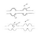
- FIG. 2is a side view of convoluted medical tubing in accordance with various aspects of the present invention.
- FIG. 3is a side view of corrugated medical tubing in accordance with various aspects of the present invention.
- FIG. 4Ais a side view of a reinforced convoluted medical tubing in an expanded or resting state in accordance with various aspects of the present invention
- FIG. 4Bis a side view of a reinforced convoluted medical tubing in a compressed state in accordance with various aspects of the present invention
- FIG. 5is a side view of corrugated tubing having asymmetric corrugations in accordance with various aspects of the present invention.
- FIGS. 6A-6Bare side views of reinforced medical tubing in accordance with various aspects of the present invention.
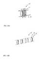
- FIG. 7illustrates a side view of dual concentric medical tubing in accordance with various aspects of the present invention.
- FIG. 8is a perspective view of telescopic medical tubing in accordance with various aspects of the present invention.
- FIGS. 9A , Bare perspective views of spiraled medical tubing in accordance with various aspects of the present invention.
- FIGS. 10A , Bare perspective views of collapsible medical tubing in accordance with various aspects of the present invention.
- FIGS. 11A , Bare cross-sectional side views of “ball-and-socket” medical tubing in accordance with various aspects of the present invention.
- FIGS. 12-13are side views of a storage or container for holding medical tubing such as those provided in reference to FIGS. 1 through 10 or described throughout this specification in accordance with various aspects of the present invention.
- medical tubing 3comprises of straight-walled plastic tubing.
- the tubing 3can carry either single or multi-lumen conduits, and can comprise of single tube 5 or multiple tubes 7 , 9 .
- the multiple tubes 7 , 9are permanently attached to each other.
- the manufacturing process utilizedis an extrusion process.
- the optimization of both material hardness and wall thicknesscalls for generally soft plastic material with moderate wall thickness (1-2 mm).
- the optimizationreflects a compromise between being kink-free, flexibility and vacuum compatible (i.e., preventing the tubing to collapse radially under vacuum).
- FIG. 2illustrates a structural re-enforcement of a thin-walled (sub-mm), but generally stiff tubing 11 .
- medical tubing 11having a generally rigid wall that utilizes a convoluted tube shape 13 as structural enforcement of the tubing is provided.
- the convoluted shapeenables the tubing to be both flexible and kink-free.
- the tubingshows a spiral-like enlargement 13 of the tube diameter.
- the wall thickness at the convolutions 13remains the same as the remaining tubing.
- the convolutionsallow the tubing to be flexible, while the generally stiff wall material enables the tubing to be vacuum-compatible (i.e., to resist radial compression).
- the increased overall tube diameter at the convolution sitesenables the tube to be kink-free when being bent or coiled. Because of the structural enforcement, the thin walled tubing can be applied for both pressure and vacuum cases.
- the convolution 13 of the tubing 11also re-enforces the tube regarding radial and axial compression, which makes the tubing vacuum compatible.
- Manufacturing processes for this kind of tubing in one aspectcomprises of blow-molding, where a (straight) tubing would be placed in the center of a mold, and applied with some positive (air) pressure while being heated. As a result, the (straight) tubing expands to take the shape of the mold. While the process of blow molding can be restricted to production of defined lengths of tubing, a blow extrusion process enables the continuous production of this type of tubing.
- a (straight) tubeis being extruded and fed into two moving “mold-like” blocks. Similarly to blow molding, application of positive pressure into the tube (while being extruded) allows the tube to take the convoluted shape. Continuous movement of the “mold-like” blocks on a rotating conveyor assembly enables production of continuous lengths of the tubing.
- a structural re-enforcement thin-walled (sub-mm) stiff tubing 15is shown.
- a medical tubing 15that utilizes a corrugated shape 17 as structural enforcement of the tubing is provided.
- the tubingprovides ring-like enlargements 17 of the tube diameter where the wall thickness at the corrugated remains the same as the remaining tubing.
- the periodic corrugations 17allow the tubing to be flexible, while the generally stiff wall material enables the tubing to be vacuum-compatible (i.e. to resist radial compression).
- the increased overall tube diameter at the corrugation sitesenables the tube to be kink-free when being bent or coiled.
- the corrugated shapeIn comparison to unshaped (straight) tubing, the corrugated shape also enables the tubing to be both flexible and kink-free. Similar to the convoluted re-enforcement, the corrugation of the tubing also re-enforces the tube regarding radial and axial compression, which makes the tubing vacuum compatible.
- Manufacturing processes for corrugated tubingcomprises of blow-molding and blow extrusion. In difference to convoluted tubing, corrugated tubing can be compressed axially. Depending on the shape of the corrugation, the corrugations can (permanently) “collapse” on themselves, which permanently reduces the size of the tubing. The tubing can again be expanded to its original length by pulling axially on the tubing.
- FIGS. 4 a and 4 billustrate a generally thin and soft tube 21 with a generally hard structural re-enforcement 23 .
- medical tubing 21that utilizes a mechanical re-enforcement 23 within soft and/or straight-walled tubing is provided.
- An example of such a re-enforcementis shown as a metallic and/or plastic coiled wire.
- the coiled wire 23is connected to the thin and soft outer tube wall.
- the generally thin wall of the tube 21allows axial compression (and size reduction) of the tube 21 , while the generally hard coiled wire 23 prevents radial compression. If the spiral coil is also stiff enough in axial direction, this tubing can also be used for vacuum applications and can be very kink-resistant.
- the tubecan be mechanically compressed axially, as shown in FIG. 4 b.
- the re-enforcement 23allows the use of a thinner tube wall of tube 21 to be both flexible and kink-free.
- the arrangementcan also sustain radial and axial compression, which makes the tubing vacuum compatible.
- tubingin one aspect would be a (steel) braided mesh, which is encapsulated within (thin-walled) straight tubing.
- corrugated tubing 25 with periodic tube enlargements 27are asymmetric in shape.
- the shaping of the corrugations 27allow the corrugations to “collapse” on themselves during axial compression, which depending on the overall tube diameter can reduce the effective length of the tubing 27 .
- ratios for expanded to collapsed tube lengthscan range from 1.5 to 4 for tube diameters ranging from 1 ⁇ 4′′ to about 1′′.
- the tubing 27remains “compressed” as the corrugations “snap” into the collapsed state.
- tube sectionsare shown in both a compressed 29 a and an extended state 29 b .
- the collapsible tubingremains flexible in both an extended and a collapsible state.
- the high flexibility in the axial directioncan cause the collapsed (extended) tubing applied with pressure (vacuum) to be forced into its extended (collapsed) state.
- FIGS. 6A ,Bmedical tubing 31 with structural re-enforcements 33 , 35 are provided.
- the soft tubing 31is re-enforced by an encapsulated, generally stiff mesh 33 . While the soft tube material allows the tubing 31 to be flexible, the generally hard plastic or metallic mesh 33 provides mechanical support for the tubing to be kink-free and vacuum resistant.
- an encapsulated coil 35gives the structural re-enforcement of thin-walled, generally soft tubing 31 .
- the generally soft and thin tube materialallows the tube 31 to be flexible and the encapsulated generally hard coil 35 prevents the tube from kinking on itself. When the spiral coil is sufficiently stiff in axial direction, this tubing can also be vacuum resistant.
- a combination of several types of tubingallows a combination of applications.
- An example that illustrates such a combinationwould be placing straight tubing into corrugated or convoluted (i.e., a very flexible and kink-free) tubing.
- the inner tubingcan be applied with vacuum (while not collapsing axially or radially), the lumen between the inner and outer tube can be applied with pressure (such as from an irrigation fluid).
- pressuresuch as from an irrigation fluid.
- a medical tubing 41 with one tube 43 positioned inside another tube 45 to combine two different types of tubingis provided.
- This configurationcan provide the simultaneous application of vacuum to the inner tube, and pressurized fluid to the outer tube or vice versa, e.g., for use in suction/irrigation systems.
- the (vacuum-compatible) inner tubingprevents both tubes from collapsing axially under vacuum
- the thin-walled outer tubingwill allow for kink-free flexibility of both tubes.
- Tube sections 61 - 69 of various diameters and/or of various lengthsare nested into each other.
- the inner and outer wall diameters of adjacent tube sectionsin one aspect are configured to deliver a snug fit, allowing sealing of the tubing.
- the tubingcan be extended into a telescope-like manner by axially moving or pulling on the tubing.
- the spiraled medical tubing 71is generated by wrapping a tube wall 73 multiple times over itself. In one aspect, by pulling one of the outer most ends away from the opposing innermost end of the overlaying tube wrapping can vary the length of the tube.
- FIGS. 10 a and 10 bdepict in one aspect a collapsible tubing 75 comprising inner rings 77 of a hard durometer that are connected to soft and thin-walled outer tubing 79 .
- the inner ringsare provided with a functional profile or configuration in that consecutive rings snap-fit to each other, thereby allowing reduction of the overall tube length and in various aspects a permanent reduction.
- the snap-fitted ringscan be disengaged, thereby increasing the overall length of the tubing. While this tubing is well suited for conducting pressurized gas or fluids, the tubing may be less suited for vacuum applications, as the thin-walled tube can axially collapse under vacuum.
- FIGS. 11 a and 11 bshow another aspect of corrugated or convoluted tubing 81 where periodic tube portions or section 83 comprises of “ball-and-socket” arrangements.
- the tubingbecomes collapsible by having neighboring elements “ball” 85 and “socket” 87 and vice versa nesting into each other, respectively.
- the shaping of the corrugations or convolutionsallow the tubing to “collapse” during axial compression, or to “extend” during axial pull, which depending on the overall tube diameter can change the effective length of the tubing.
- the tubing 49is stored in a coiled fashion inside a storage container 51 that has a housing 56 and a shaft 57 enclosed in, and connected to, the housing. In one aspect, the tubing 49 is wrapped around the shaft 57 . By pulling the tubing out of the container, any needed length of tubing can be dispensed.
- the tubing 53is stored in a double-coiled fashion inside a storage container 55 that has a housing 58 and two parallel shafts 59 enclosed in, and connected to, the housing.
- the double coiling of the tubing 53 in one aspectis generated by wrapping the collapsed or compressed tubing around the two shafts 59 , either encircling the shafts or in a “figure eight” pattern, which prevents twisting of tubing when dispensing the tubing from the container 55 .
- twistingwhich can lead to kinking
- the shafts 57 , 59 in FIGS. 12 and 13are rotatable.
- kink-resistant and flexible plastic tubingare provided for utilization with surgical instrumentation, such as in gas insufflation systems and/or suction/irrigation system in laparoscopic or general surgery.
- the tubingis mechanically flexible and kink-resistant due to the structural enforcement of a thin wall, which makes the tubing also lightweight.
- Examplesare of various aspects are provided for corrugated, convoluted and also collapsible tubing, as well as tube structures that utilize coiled or braided wall-enforcements.
- Combination of various tubesprovides a mechanical enforcement that can allow simultaneous application of vacuum/pressure, such as for suction/irrigation systems.
- Continuous plastic extrusion, co-extrusion, blow-mold, or over-mold processescan produce the various aspects of various tubing provided.
- Various aspects of various packaging and/or storing of various tubesare also provided that can, for example, provide small-sized tube dispensers.
- the present inventionprovides gas insufflation, suction and irrigation medical tubing.
Landscapes
- Health & Medical Sciences (AREA)
- Engineering & Computer Science (AREA)
- Heart & Thoracic Surgery (AREA)
- General Engineering & Computer Science (AREA)
- Anesthesiology (AREA)
- Public Health (AREA)
- Biomedical Technology (AREA)
- Hematology (AREA)
- Life Sciences & Earth Sciences (AREA)
- Animal Behavior & Ethology (AREA)
- General Health & Medical Sciences (AREA)
- Veterinary Medicine (AREA)
- Mechanical Engineering (AREA)
- Pulmonology (AREA)
- Vascular Medicine (AREA)
- Surgery (AREA)
- Oral & Maxillofacial Surgery (AREA)
- External Artificial Organs (AREA)
- Rigid Pipes And Flexible Pipes (AREA)
- Media Introduction/Drainage Providing Device (AREA)
Abstract
Description
Claims (6)
Priority Applications (1)
| Application Number | Priority Date | Filing Date | Title |
|---|---|---|---|
| US14/699,954US9962537B2 (en) | 2006-03-01 | 2015-04-29 | Gas insufflation and suction/irrigation tubing |
Applications Claiming Priority (3)
| Application Number | Priority Date | Filing Date | Title |
|---|---|---|---|
| US77795906P | 2006-03-01 | 2006-03-01 | |
| US11/680,835US20070208300A1 (en) | 2006-03-01 | 2007-03-01 | Gas insufflation and suction/irrigation tubing |
| US14/699,954US9962537B2 (en) | 2006-03-01 | 2015-04-29 | Gas insufflation and suction/irrigation tubing |
Related Parent Applications (1)
| Application Number | Title | Priority Date | Filing Date |
|---|---|---|---|
| US11/680,835ContinuationUS20070208300A1 (en) | 2006-03-01 | 2007-03-01 | Gas insufflation and suction/irrigation tubing |
Publications (2)
| Publication Number | Publication Date |
|---|---|
| US20150258323A1 US20150258323A1 (en) | 2015-09-17 |
| US9962537B2true US9962537B2 (en) | 2018-05-08 |
Family
ID=38475676
Family Applications (2)
| Application Number | Title | Priority Date | Filing Date |
|---|---|---|---|
| US11/680,835AbandonedUS20070208300A1 (en) | 2006-03-01 | 2007-03-01 | Gas insufflation and suction/irrigation tubing |
| US14/699,954Active2028-03-23US9962537B2 (en) | 2006-03-01 | 2015-04-29 | Gas insufflation and suction/irrigation tubing |
Family Applications Before (1)
| Application Number | Title | Priority Date | Filing Date |
|---|---|---|---|
| US11/680,835AbandonedUS20070208300A1 (en) | 2006-03-01 | 2007-03-01 | Gas insufflation and suction/irrigation tubing |
Country Status (4)
| Country | Link |
|---|---|
| US (2) | US20070208300A1 (en) |
| EP (1) | EP1988959A2 (en) |
| AU (1) | AU2007223403B2 (en) |
| WO (1) | WO2007103715A2 (en) |
Families Citing this family (33)
| Publication number | Priority date | Publication date | Assignee | Title |
|---|---|---|---|---|
| US7771411B2 (en) | 2004-09-24 | 2010-08-10 | Syntheon, Llc | Methods for operating a selective stiffening catheter |
| US20080012331A1 (en)* | 2006-03-01 | 2008-01-17 | Dormont Manufacturing Company | Quiet gas connector |
| US8556804B2 (en) | 2006-05-22 | 2013-10-15 | Syntheon, Llc | Torque-transmitting, variably flexible insertion device and method for transmitting torque and variably flexing an insertion device |
| US10123683B2 (en) | 2006-03-02 | 2018-11-13 | Syntheon, Llc | Variably flexible insertion device and method for variably flexing an insertion device |
| US7988621B2 (en) | 2006-08-10 | 2011-08-02 | Syntheon, Llc | Torque-transmitting, variably-flexible, corrugated insertion device and method for transmitting torque and variably flexing a corrugated insertion device |
| US9155451B2 (en) | 2006-03-02 | 2015-10-13 | Syntheon, Llc | Variably flexible insertion device and method for variably flexing an insertion device |
| US9814372B2 (en)* | 2007-06-27 | 2017-11-14 | Syntheon, Llc | Torque-transmitting, variably-flexible, locking insertion device and method for operating the insertion device |
| US8092374B2 (en) | 2006-03-02 | 2012-01-10 | Kevin Smith | Variably flexible insertion device and method for variably flexing an insertion device |
| US10278682B2 (en)* | 2007-01-30 | 2019-05-07 | Loma Vista Medical, Inc. | Sheaths for medical devices |
| EP3075406A1 (en) | 2008-04-30 | 2016-10-05 | ResMed R&D Germany GmbH | Apparatus and method for controlled delivery of a breathing gas to the respiratory tracts of a user |
| NZ618492A (en) | 2008-06-05 | 2015-09-25 | Resmed Ltd | Treatment of respiratory conditions |
| US9125999B2 (en) | 2009-05-18 | 2015-09-08 | Adamis Pharmaceuticals Corporation | Dry powder inhaler dose counters |
| US8978648B2 (en)* | 2010-04-07 | 2015-03-17 | Resmed Limited | Air delivery conduit |
| US8574218B2 (en) | 2010-05-10 | 2013-11-05 | Cook Medical Technologies Llc | Catheter, fluid conveying method, and percutaneous procedure |
| WO2013037370A1 (en) | 2011-09-12 | 2013-03-21 | Safeair Ag | Methods of manufacturing flexible polymeric medical spiral tubings, tubings made by the methods and uses of the tubings |
| WO2013037830A1 (en)* | 2011-09-12 | 2013-03-21 | Safeair Ag | An electrosurgical pencil with a smoke evacuation tube |
| WO2013061187A1 (en)* | 2011-10-27 | 2013-05-02 | Koninklijke Philips Electronics N.V. | Collapsible patient conduit a respiratory therapy system. |
| US9861777B2 (en)* | 2012-02-06 | 2018-01-09 | Neotech Products Llc | Apparatus for control of oxygen and/or air flow to nasal prongs |
| EP3102277B1 (en)* | 2014-02-17 | 2021-05-12 | Clearflow, Inc. | A device for clearing obstructions from a multi-lumen medical tube |
| EP3107617B1 (en) | 2014-02-17 | 2023-07-19 | Clearflow, Inc. | Medical tube clearance device |
| EP3656428B1 (en)* | 2015-09-30 | 2021-06-16 | Applied Medical Resources Corporation | Insufflation stabilization system |
| GB2543544A (en)* | 2015-10-21 | 2017-04-26 | Brightwake Ltd | Wound dressing |
| GB201608099D0 (en) | 2016-05-09 | 2016-06-22 | Convatec Technologies Inc | Negative pressure wound dressing |
| MX2019000232A (en) | 2016-07-08 | 2019-11-12 | Convatec Technologies Inc | Fluid flow sensing. |
| DK3481349T3 (en) | 2016-07-08 | 2021-07-12 | Convatec Technologies Inc | Flexible vacuum system |
| EP3481348A4 (en) | 2016-07-08 | 2020-02-26 | ConvaTec Technologies Inc. | Fluid collection apparatus |
| US10751507B2 (en) | 2017-04-10 | 2020-08-25 | Syn Variflex, Llc | Thermally controlled variable-flexibility catheters and methods of manufacturing same |
| US10519634B2 (en)* | 2017-04-18 | 2019-12-31 | Flextexx Inc. | Curb box and method |
| US10772438B2 (en)* | 2017-08-23 | 2020-09-15 | Sleep Number Corporation | Air system for a bed |
| US20220395670A1 (en)* | 2019-10-03 | 2022-12-15 | Ramot Biomedical Engineering Ltd. | Catheter fixation device |
| WO2021214373A1 (en)* | 2020-04-22 | 2021-10-28 | Dolea Oy | A disposable fibre-based evacuator tip for a medical suction device and a method for manufacturing the tip |
| EP4172524A1 (en) | 2020-06-24 | 2023-05-03 | Winston Products LLC | Expandable hose |
| WO2024205871A1 (en)* | 2023-03-29 | 2024-10-03 | Carefusion 303, Inc. | Telescopic tubing extension set |
Citations (72)
| Publication number | Priority date | Publication date | Assignee | Title |
|---|---|---|---|---|
| US1596754A (en) | 1923-10-30 | 1926-08-17 | Judson D Moschelle | Reenforced tubing |
| US2458305A (en) | 1947-04-26 | 1949-01-04 | Richard D Sanders | Tubular article comprising rubberlike material |
| US2836181A (en) | 1955-01-17 | 1958-05-27 | Chemstrand Corp | Flexible nylon tube and method for preparing same |
| US2963749A (en) | 1958-11-13 | 1960-12-13 | Hoover Co | Continuous method of and apparatus for making extensible and flexible hose |
| US3122171A (en) | 1960-10-19 | 1964-02-25 | Carlon Products Corp | Flexible plastic tubing |
| US3388705A (en) | 1965-04-08 | 1968-06-18 | Foregger Company Inc | Universal endotracheal tube coupling or adaptor |
| US3416531A (en) | 1964-01-02 | 1968-12-17 | Edwards Miles Lowell | Catheter |
| US3585707A (en) | 1966-04-13 | 1971-06-22 | Cordis Corp | Method of making tubular products |
| US3598126A (en) | 1968-04-30 | 1971-08-10 | Baxter Laboratories Inc | Vascular canula for medical applications |
| US3692889A (en) | 1970-03-17 | 1972-09-19 | Raybestos Manhattan Inc | Method and apparatus for forming corrugated plastic tubing |
| US3751541A (en) | 1967-11-29 | 1973-08-07 | Hegler Wilhelm | Process of forming plastic tubing which is partially corrugated |
| US3794080A (en) | 1972-08-18 | 1974-02-26 | Becton Dickinson Co | Corrugated flexible hose |
| US3908704A (en) | 1958-06-12 | 1975-09-30 | Penntube Plastics Company | Corrugated tubing |
| US3913622A (en) | 1973-10-19 | 1975-10-21 | Dayco Corp | Gas conduit and method of making same |
| US3919367A (en) | 1972-07-13 | 1975-11-11 | Ernest J Maroschak | Method for molding plastic pipe with enlarged portions formed therein |
| US4000341A (en) | 1975-05-23 | 1976-12-28 | Minnesota Mining And Manufacturing Company | Autoclavable, corrugated, respiratory care tubing |
| US4017244A (en) | 1975-04-15 | 1977-04-12 | Andrea Giuliano Vellani | Device for the molding of corrugated pipe from extruded thermoplastic materials |
| US4196031A (en) | 1978-03-10 | 1980-04-01 | Titeflex Corporation | Method of making a preformed semirigid plastic hose wrapped with a wire spiral |
| US4336798A (en) | 1980-10-06 | 1982-06-29 | Anthony V. Beran | Medical corrugated respiratory tube |
| US4360104A (en) | 1979-08-29 | 1982-11-23 | Volker Lang | Universal sterile closed hose system for respiration therapy apparatus |
| US4368088A (en) | 1979-12-20 | 1983-01-11 | Toyo Kagaku Kabushiki Kaisha | Method of manufacturing corrugated tube |
| US4377545A (en) | 1981-06-16 | 1983-03-22 | Borg-Warner Chemicals, Inc. | Method of making corrugated reinforced thermoplastic pipe |
| US4593690A (en) | 1984-06-28 | 1986-06-10 | David S. Sheridan | Endotracheal tubes with improved proximal end connector units |
| US4653542A (en) | 1980-10-02 | 1987-03-31 | The Kendall Company | Medical tubing and connector |
| US4737153A (en) | 1986-02-07 | 1988-04-12 | Kuraray Co., Ltd. | Reinforced therapeutic tube |
| US4852564A (en) | 1984-06-28 | 1989-08-01 | Sheridan Catheter Corp. | Flexible connectors for medico-surgical tubes |
| US4873048A (en) | 1985-07-24 | 1989-10-10 | Oy Uponor Ab | Method for the formation of a hole in a plastic pipe |
| US4900314A (en) | 1988-02-01 | 1990-02-13 | Fbk International Corporation | Collapse-resistant tubing for medical use |
| US4966202A (en) | 1988-11-14 | 1990-10-30 | Dayco Products, Inc. | Shape retention hose construction |
| US4990143A (en) | 1990-04-09 | 1991-02-05 | Sheridan Catheter Corporation | Reinforced medico-surgical tubes |
| US4998527A (en) | 1989-07-27 | 1991-03-12 | Percutaneous Technologies Inc. | Endoscopic abdominal, urological, and gynecological tissue removing device |
| US5019057A (en) | 1989-10-23 | 1991-05-28 | Cordis Corporation | Catheter having reinforcing strands |
| US5139730A (en) | 1989-10-27 | 1992-08-18 | Uponor N.V. | Method and apparatus for manufacturing ribbed pipe |
| US5222949A (en) | 1991-07-23 | 1993-06-29 | Intermed, Inc. | Flexible, noncollapsible catheter tube with hard and soft regions |
| US5454795A (en) | 1994-06-27 | 1995-10-03 | Target Therapeutics, Inc. | Kink-free spiral-wound catheter |
| US5476630A (en) | 1991-05-06 | 1995-12-19 | Orsing; Ernst | Method for manufacturing dental aspirators |
| US5538513A (en) | 1992-10-23 | 1996-07-23 | Terumo Kabushiki Kaisha | Catheter tube having a filamentous reinforcing layer |
| US5630806A (en) | 1991-08-13 | 1997-05-20 | Hudson International Conductors | Spiral wrapped medical tubing |
| US5702373A (en) | 1995-08-31 | 1997-12-30 | Target Therapeutics, Inc. | Composite super-elastic alloy braid reinforced catheter |
| US5720504A (en) | 1996-03-29 | 1998-02-24 | Dormont Manufacturing Company | Convoluted fluid connector assembly with hardened end portion |
| US5755704A (en) | 1996-10-29 | 1998-05-26 | Medtronic, Inc. | Thinwall guide catheter |
| US5785998A (en) | 1991-09-12 | 1998-07-28 | The United States Of America As Represented By The Department Of Health And Human Services | Apparatus for making ultra thin walled wire reinforced endotracheal tubing |
| US5792401A (en) | 1983-12-12 | 1998-08-11 | Burnham; Warren R. | Method for making a tubular product |
| US5795341A (en) | 1994-11-10 | 1998-08-18 | Target Therapeutics, Inc. | High performance spiral-wound catheter |
| US5827242A (en) | 1996-06-21 | 1998-10-27 | Medtronic, Inc. | Reinforced catheter body and method for its fabrication |
| US5947940A (en) | 1997-06-23 | 1999-09-07 | Beisel; Robert F. | Catheter reinforced to prevent luminal collapse and tensile failure thereof |
| US6021816A (en) | 1997-02-25 | 2000-02-08 | Ems-Inventa Ag | Corrugated pipe |
| US6102078A (en) | 1994-05-24 | 2000-08-15 | Kramer, Jr.; Vance M. | Rubber tubing with axially spaced annularly corrugated flexible segments |
| US6258080B1 (en) | 1997-07-01 | 2001-07-10 | Target Therapeutics, Inc. | Kink-free spiral-wound catheter |
| US6394145B1 (en) | 1997-07-24 | 2002-05-28 | Norton Gessil | Flexible conduit, such as pipe for medical or surgical use |
| US6398266B1 (en) | 1999-09-22 | 2002-06-04 | Ballard Medical Products | Collapse resistant popoid connector |
| US20030009151A1 (en) | 2001-07-03 | 2003-01-09 | Scimed Life Systems, Inc. | Biaxially oriented multilayer polymer tube for medical devices |
| US6554820B1 (en) | 2000-03-08 | 2003-04-29 | Scimed Life Systems, Inc. | Composite flexible tube for medical applications |
| US6569148B2 (en) | 1996-05-20 | 2003-05-27 | Medtronic Ave, Inc. | Methods for emboli containment |
| US6616651B1 (en) | 2000-11-17 | 2003-09-09 | Robert C. Stevens | Intravascular microcatheter with embedded helical coil reinforcement member and methods and apparatus for making same |
| US6626889B1 (en) | 2001-07-25 | 2003-09-30 | Advanced Cardiovascular Systems, Inc. | Thin-walled guiding catheter with improved radiopacity |
| US20040102804A1 (en) | 1999-08-10 | 2004-05-27 | Chin Albert K. | Apparatus and methods for endoscopic surgical procedures |
| US6764627B2 (en) | 2000-03-23 | 2004-07-20 | Hahn Elastomer Corporation | Method of making corrugated part |
| US20040153049A1 (en) | 2002-10-10 | 2004-08-05 | Hewitt Todd J. | Wire braid-reinforced microcatheter |
| US6793621B2 (en)* | 2001-03-08 | 2004-09-21 | Atropos Limited | Colonic overtube |
| US20040210281A1 (en) | 2003-03-17 | 2004-10-21 | Elizabeth Dzeng | Transesophageal heat exchange catheter for cooling of the heart |
| US20050010194A1 (en) | 2003-07-09 | 2005-01-13 | Scimed Life Systems, Inc. | Method of forming catheter distal tip |
| US20050043713A1 (en) | 2003-08-20 | 2005-02-24 | Scimed Life Systems, Inc. | Catheter with thin-walled braid |
| US20050119686A1 (en) | 2003-12-01 | 2005-06-02 | Clubb Thomas L. | Rapid exchange catheters with tandem lumens |
| US20050161101A1 (en) | 2003-12-31 | 2005-07-28 | Wisdom Jack L. | Highly kink-resistant corrugated tubing |
| US20050165366A1 (en) | 2004-01-28 | 2005-07-28 | Brustad John R. | Medical tubing having variable characteristics and method of making same |
| US20050177168A1 (en) | 2004-02-11 | 2005-08-11 | Medtronic, Inc. | High speed surgical cutting instrument |
| US20060001263A1 (en) | 2004-07-03 | 2006-01-05 | Hegler Ralph P | Method of continuously producing a twin-wall pipe with a socket, twin-wall pipe and apparatus for implementing the method and for producing the twin-wall pipe |
| US7811253B2 (en) | 2004-12-09 | 2010-10-12 | Applied Medical Resources Corporation | Insufflation gas warmer and humidifier |
| US7942862B2 (en) | 2003-01-17 | 2011-05-17 | Applied Medical Resources Corporation | Surgical access apparatus and method |
| US8028395B2 (en) | 2006-10-06 | 2011-10-04 | Applied Medical Resources Corporation | Method for manufacturing high flow insufflation needle stylet |
| US8105285B2 (en) | 2003-01-17 | 2012-01-31 | Applied Medical Resources Corporation | Surgical access apparatus and method |
Family Cites Families (19)
| Publication number | Priority date | Publication date | Assignee | Title |
|---|---|---|---|---|
| US3089535A (en)* | 1958-10-11 | 1963-05-14 | Kessler & Co Tech Chem Gmbh | Apparatus for making a wire reinforced flexible hose |
| US4342612A (en)* | 1978-03-10 | 1982-08-03 | Titeflex Corporation | Method of making a preformed semirigid plastic hose wrapped with a wire spiral |
| US4487660A (en)* | 1980-10-31 | 1984-12-11 | Electric Power Research Institute | Multiple wall structure for flexible cable using tubular and spiral corrugations |
| US4335756A (en)* | 1981-01-21 | 1982-06-22 | Texas Medical Products, Inc. | Sterilized medical tubing cover |
| US4693690A (en)* | 1986-03-10 | 1987-09-15 | Henderson Elvin J | Quick drain assembly for boat engine |
| US4987895A (en)* | 1986-10-06 | 1991-01-29 | Heimlich Henry J | Tracheal tube |
| GB8627929D0 (en)* | 1986-11-21 | 1986-12-31 | Standard Hose Ltd | Flexible hose |
| US5193756A (en)* | 1991-06-24 | 1993-03-16 | Hughes Aircraft Company | Figure eight linear dispenser |
| US5720719A (en)* | 1992-08-12 | 1998-02-24 | Vidamed, Inc. | Ablative catheter with conformable body |
| US5600752A (en)* | 1994-03-11 | 1997-02-04 | Industrial Design Laboratories, Inc. | Flexible gas hose assembly with concentric helical tube members having reinforcement spring coils |
| US5902290A (en)* | 1994-03-14 | 1999-05-11 | Advanced Cardiovascular Systems, Inc. | Catheter providing intraluminal access |
| US5762631A (en)* | 1995-07-14 | 1998-06-09 | Localmed, Inc. | Method and system for reduced friction introduction of coaxial catheters |
| US5632734A (en)* | 1995-10-10 | 1997-05-27 | Guided Medical Systems, Inc. | Catheter shape control by collapsible inner tubular member |
| US6016848A (en)* | 1996-07-16 | 2000-01-25 | W. L. Gore & Associates, Inc. | Fluoropolymer tubes and methods of making same |
| US6186986B1 (en)* | 1998-01-21 | 2001-02-13 | St. Jude Medical Cardiovascular Group, Inc. | Micro-catheters and methods of their manufacture |
| US6511462B1 (en)* | 1999-07-16 | 2003-01-28 | Terumo Kabushiki Kaisha | Catheter and method of manufacturing the same |
| US6830794B2 (en)* | 1999-08-13 | 2004-12-14 | Richard G. Cartledge | Insulated intravenous administration tubing |
| US6431218B1 (en)* | 2000-09-28 | 2002-08-13 | Vital Signs, Inc. | Multi-lumen hose with at least one substantially planar inner partition and methods of manufacturing the same |
| US7504252B2 (en)* | 2004-06-14 | 2009-03-17 | Cytyc Corporation | Apparatus and methods for scanning and producing biological specimen film strips |
- 2007
- 2007-03-01AUAU2007223403Apatent/AU2007223403B2/ennot_activeCeased
- 2007-03-01EPEP07757698Apatent/EP1988959A2/ennot_activeWithdrawn
- 2007-03-01USUS11/680,835patent/US20070208300A1/ennot_activeAbandoned
- 2007-03-01WOPCT/US2007/063049patent/WO2007103715A2/enactiveApplication Filing
- 2015
- 2015-04-29USUS14/699,954patent/US9962537B2/enactiveActive
Patent Citations (73)
| Publication number | Priority date | Publication date | Assignee | Title |
|---|---|---|---|---|
| US1596754A (en) | 1923-10-30 | 1926-08-17 | Judson D Moschelle | Reenforced tubing |
| US2458305A (en) | 1947-04-26 | 1949-01-04 | Richard D Sanders | Tubular article comprising rubberlike material |
| US2836181A (en) | 1955-01-17 | 1958-05-27 | Chemstrand Corp | Flexible nylon tube and method for preparing same |
| US3908704A (en) | 1958-06-12 | 1975-09-30 | Penntube Plastics Company | Corrugated tubing |
| US2963749A (en) | 1958-11-13 | 1960-12-13 | Hoover Co | Continuous method of and apparatus for making extensible and flexible hose |
| US3122171A (en) | 1960-10-19 | 1964-02-25 | Carlon Products Corp | Flexible plastic tubing |
| US3416531A (en) | 1964-01-02 | 1968-12-17 | Edwards Miles Lowell | Catheter |
| US3388705A (en) | 1965-04-08 | 1968-06-18 | Foregger Company Inc | Universal endotracheal tube coupling or adaptor |
| US3585707A (en) | 1966-04-13 | 1971-06-22 | Cordis Corp | Method of making tubular products |
| US3751541A (en) | 1967-11-29 | 1973-08-07 | Hegler Wilhelm | Process of forming plastic tubing which is partially corrugated |
| US3598126A (en) | 1968-04-30 | 1971-08-10 | Baxter Laboratories Inc | Vascular canula for medical applications |
| US3692889A (en) | 1970-03-17 | 1972-09-19 | Raybestos Manhattan Inc | Method and apparatus for forming corrugated plastic tubing |
| US3919367A (en) | 1972-07-13 | 1975-11-11 | Ernest J Maroschak | Method for molding plastic pipe with enlarged portions formed therein |
| US3794080A (en) | 1972-08-18 | 1974-02-26 | Becton Dickinson Co | Corrugated flexible hose |
| US3913622A (en) | 1973-10-19 | 1975-10-21 | Dayco Corp | Gas conduit and method of making same |
| US4017244A (en) | 1975-04-15 | 1977-04-12 | Andrea Giuliano Vellani | Device for the molding of corrugated pipe from extruded thermoplastic materials |
| US4000341A (en) | 1975-05-23 | 1976-12-28 | Minnesota Mining And Manufacturing Company | Autoclavable, corrugated, respiratory care tubing |
| US4196031A (en) | 1978-03-10 | 1980-04-01 | Titeflex Corporation | Method of making a preformed semirigid plastic hose wrapped with a wire spiral |
| US4360104A (en) | 1979-08-29 | 1982-11-23 | Volker Lang | Universal sterile closed hose system for respiration therapy apparatus |
| US4368088A (en) | 1979-12-20 | 1983-01-11 | Toyo Kagaku Kabushiki Kaisha | Method of manufacturing corrugated tube |
| US4653542A (en) | 1980-10-02 | 1987-03-31 | The Kendall Company | Medical tubing and connector |
| US4336798A (en) | 1980-10-06 | 1982-06-29 | Anthony V. Beran | Medical corrugated respiratory tube |
| US4377545A (en) | 1981-06-16 | 1983-03-22 | Borg-Warner Chemicals, Inc. | Method of making corrugated reinforced thermoplastic pipe |
| US5792401A (en) | 1983-12-12 | 1998-08-11 | Burnham; Warren R. | Method for making a tubular product |
| US4852564A (en) | 1984-06-28 | 1989-08-01 | Sheridan Catheter Corp. | Flexible connectors for medico-surgical tubes |
| US4593690A (en) | 1984-06-28 | 1986-06-10 | David S. Sheridan | Endotracheal tubes with improved proximal end connector units |
| US4873048A (en) | 1985-07-24 | 1989-10-10 | Oy Uponor Ab | Method for the formation of a hole in a plastic pipe |
| US4737153A (en) | 1986-02-07 | 1988-04-12 | Kuraray Co., Ltd. | Reinforced therapeutic tube |
| US4900314A (en) | 1988-02-01 | 1990-02-13 | Fbk International Corporation | Collapse-resistant tubing for medical use |
| US4966202A (en) | 1988-11-14 | 1990-10-30 | Dayco Products, Inc. | Shape retention hose construction |
| US4998527A (en) | 1989-07-27 | 1991-03-12 | Percutaneous Technologies Inc. | Endoscopic abdominal, urological, and gynecological tissue removing device |
| US5019057A (en) | 1989-10-23 | 1991-05-28 | Cordis Corporation | Catheter having reinforcing strands |
| US5139730A (en) | 1989-10-27 | 1992-08-18 | Uponor N.V. | Method and apparatus for manufacturing ribbed pipe |
| US4990143A (en) | 1990-04-09 | 1991-02-05 | Sheridan Catheter Corporation | Reinforced medico-surgical tubes |
| US5476630A (en) | 1991-05-06 | 1995-12-19 | Orsing; Ernst | Method for manufacturing dental aspirators |
| US5222949A (en) | 1991-07-23 | 1993-06-29 | Intermed, Inc. | Flexible, noncollapsible catheter tube with hard and soft regions |
| US5630806A (en) | 1991-08-13 | 1997-05-20 | Hudson International Conductors | Spiral wrapped medical tubing |
| US5785998A (en) | 1991-09-12 | 1998-07-28 | The United States Of America As Represented By The Department Of Health And Human Services | Apparatus for making ultra thin walled wire reinforced endotracheal tubing |
| US5538513A (en) | 1992-10-23 | 1996-07-23 | Terumo Kabushiki Kaisha | Catheter tube having a filamentous reinforcing layer |
| US6102078A (en) | 1994-05-24 | 2000-08-15 | Kramer, Jr.; Vance M. | Rubber tubing with axially spaced annularly corrugated flexible segments |
| US5695483A (en) | 1994-06-27 | 1997-12-09 | Target Therapeutics Inc. | Kink-free spiral-wound catheter |
| US5454795A (en) | 1994-06-27 | 1995-10-03 | Target Therapeutics, Inc. | Kink-free spiral-wound catheter |
| US5795341A (en) | 1994-11-10 | 1998-08-18 | Target Therapeutics, Inc. | High performance spiral-wound catheter |
| US5702373A (en) | 1995-08-31 | 1997-12-30 | Target Therapeutics, Inc. | Composite super-elastic alloy braid reinforced catheter |
| US5720504A (en) | 1996-03-29 | 1998-02-24 | Dormont Manufacturing Company | Convoluted fluid connector assembly with hardened end portion |
| US6569148B2 (en) | 1996-05-20 | 2003-05-27 | Medtronic Ave, Inc. | Methods for emboli containment |
| US5827242A (en) | 1996-06-21 | 1998-10-27 | Medtronic, Inc. | Reinforced catheter body and method for its fabrication |
| US5755704A (en) | 1996-10-29 | 1998-05-26 | Medtronic, Inc. | Thinwall guide catheter |
| US6021816A (en) | 1997-02-25 | 2000-02-08 | Ems-Inventa Ag | Corrugated pipe |
| US5947940A (en) | 1997-06-23 | 1999-09-07 | Beisel; Robert F. | Catheter reinforced to prevent luminal collapse and tensile failure thereof |
| US6258080B1 (en) | 1997-07-01 | 2001-07-10 | Target Therapeutics, Inc. | Kink-free spiral-wound catheter |
| US6394145B1 (en) | 1997-07-24 | 2002-05-28 | Norton Gessil | Flexible conduit, such as pipe for medical or surgical use |
| US20040102804A1 (en) | 1999-08-10 | 2004-05-27 | Chin Albert K. | Apparatus and methods for endoscopic surgical procedures |
| US6398266B1 (en) | 1999-09-22 | 2002-06-04 | Ballard Medical Products | Collapse resistant popoid connector |
| US6554820B1 (en) | 2000-03-08 | 2003-04-29 | Scimed Life Systems, Inc. | Composite flexible tube for medical applications |
| US6764627B2 (en) | 2000-03-23 | 2004-07-20 | Hahn Elastomer Corporation | Method of making corrugated part |
| US6616651B1 (en) | 2000-11-17 | 2003-09-09 | Robert C. Stevens | Intravascular microcatheter with embedded helical coil reinforcement member and methods and apparatus for making same |
| US6793621B2 (en)* | 2001-03-08 | 2004-09-21 | Atropos Limited | Colonic overtube |
| US20030009151A1 (en) | 2001-07-03 | 2003-01-09 | Scimed Life Systems, Inc. | Biaxially oriented multilayer polymer tube for medical devices |
| US6626889B1 (en) | 2001-07-25 | 2003-09-30 | Advanced Cardiovascular Systems, Inc. | Thin-walled guiding catheter with improved radiopacity |
| US20040153049A1 (en) | 2002-10-10 | 2004-08-05 | Hewitt Todd J. | Wire braid-reinforced microcatheter |
| US7942862B2 (en) | 2003-01-17 | 2011-05-17 | Applied Medical Resources Corporation | Surgical access apparatus and method |
| US8105285B2 (en) | 2003-01-17 | 2012-01-31 | Applied Medical Resources Corporation | Surgical access apparatus and method |
| US20040210281A1 (en) | 2003-03-17 | 2004-10-21 | Elizabeth Dzeng | Transesophageal heat exchange catheter for cooling of the heart |
| US20050010194A1 (en) | 2003-07-09 | 2005-01-13 | Scimed Life Systems, Inc. | Method of forming catheter distal tip |
| US20050043713A1 (en) | 2003-08-20 | 2005-02-24 | Scimed Life Systems, Inc. | Catheter with thin-walled braid |
| US20050119686A1 (en) | 2003-12-01 | 2005-06-02 | Clubb Thomas L. | Rapid exchange catheters with tandem lumens |
| US20050161101A1 (en) | 2003-12-31 | 2005-07-28 | Wisdom Jack L. | Highly kink-resistant corrugated tubing |
| US20050165366A1 (en) | 2004-01-28 | 2005-07-28 | Brustad John R. | Medical tubing having variable characteristics and method of making same |
| US20050177168A1 (en) | 2004-02-11 | 2005-08-11 | Medtronic, Inc. | High speed surgical cutting instrument |
| US20060001263A1 (en) | 2004-07-03 | 2006-01-05 | Hegler Ralph P | Method of continuously producing a twin-wall pipe with a socket, twin-wall pipe and apparatus for implementing the method and for producing the twin-wall pipe |
| US7811253B2 (en) | 2004-12-09 | 2010-10-12 | Applied Medical Resources Corporation | Insufflation gas warmer and humidifier |
| US8028395B2 (en) | 2006-10-06 | 2011-10-04 | Applied Medical Resources Corporation | Method for manufacturing high flow insufflation needle stylet |
Also Published As
| Publication number | Publication date |
|---|---|
| EP1988959A2 (en) | 2008-11-12 |
| US20150258323A1 (en) | 2015-09-17 |
| WO2007103715A2 (en) | 2007-09-13 |
| AU2007223403A1 (en) | 2007-09-13 |
| AU2007223403B2 (en) | 2013-03-28 |
| US20070208300A1 (en) | 2007-09-06 |
| WO2007103715A3 (en) | 2008-03-06 |
Similar Documents
| Publication | Publication Date | Title |
|---|---|---|
| US9962537B2 (en) | Gas insufflation and suction/irrigation tubing | |
| JP4441490B2 (en) | Steerable catheter and method for manufacturing the same | |
| US6398266B1 (en) | Collapse resistant popoid connector | |
| US8622994B2 (en) | Composite flexible tube for medical applications | |
| US8684911B2 (en) | Self-propelled endoscopic device | |
| US20020120321A1 (en) | Stent retention mechanism | |
| US8088100B2 (en) | Reinforced rewrappable balloon | |
| JP2023520780A (en) | Layered wall for device hardening | |
| US20140130929A1 (en) | Seamless helically corrugated tubes and methods of manufacture | |
| AU2014292955A1 (en) | Balloon catheter systems and methods | |
| CN1681446A (en) | Balloon alignment and collapse system | |
| AU6905998A (en) | Cuffed tubes | |
| WO2020046979A1 (en) | Devices and systems for body cavities and methods of use | |
| AU2013206531B2 (en) | "Gas insufflation suction and irrigation medical tubing" | |
| CN117442142B (en) | Growing robotic arm | |
| CN218871048U (en) | Tubular element expander and tubular element | |
| EP2911570A1 (en) | A flexible and extensible tubular guide and manufacture process thereof | |
| JP5918853B2 (en) | Method for producing flexible polymer spiral medical tube, tube made by the production method and use of the tube | |
| CN113332567A (en) | Balloon dilatation catheter | |
| JPH06217937A (en) | Endoscope | |
| CN217208152U (en) | Reinforced rib type double-wall helical bellows | |
| CN223232674U (en) | Telescopic sleeve and flexible member conveying device | |
| CN217310395U (en) | Surgical attachment and surgical robot system | |
| JP4955491B2 (en) | Endoscope | |
| US11413435B2 (en) | Methods for construction of medical devices containing toroidal balloons |
Legal Events
| Date | Code | Title | Description |
|---|---|---|---|
| AS | Assignment | Owner name:APPLIED MEDICAL RESOURCES CORPORATION, CALIFORNIA Free format text:ASSIGNMENT OF ASSIGNORS INTEREST;ASSIGNORS:PRAVONG, BOUN;PRAVONGVIENGKHAM, KENNII;HILAL, NABIL;AND OTHERS;REEL/FRAME:035735/0995 Effective date:20070228 | |
| AS | Assignment | Owner name:CITIBANK, N.A., AS ADMINISTRATIVE AGENT, TEXAS Free format text:SECURITY INTEREST;ASSIGNOR:APPLIED MEDICAL RESOURCES CORPORATION;REEL/FRAME:035799/0206 Effective date:20150529 | |
| AS | Assignment | Owner name:JPMORGAN CHASE BANK, N.A., AS ADMINISTRATIVE AGENT, ILLINOIS Free format text:SECURITY INTEREST;ASSIGNOR:APPLIED MEDICAL RESOURCES CORPORATION;REEL/FRAME:042669/0725 Effective date:20170531 Owner name:JPMORGAN CHASE BANK, N.A., AS ADMINISTRATIVE AGENT Free format text:SECURITY INTEREST;ASSIGNOR:APPLIED MEDICAL RESOURCES CORPORATION;REEL/FRAME:042669/0725 Effective date:20170531 | |
| AS | Assignment | Owner name:APPLIED MEDICAL RESOURCES CORPORATION, CALIFORNIA Free format text:RELEASE BY SECURED PARTY;ASSIGNOR:CITIBANK, N.A., AS ADMINISTRATIVE AGENT;REEL/FRAME:042692/0404 Effective date:20170531 | |
| STCF | Information on status: patent grant | Free format text:PATENTED CASE | |
| AS | Assignment | Owner name:CITIBANK, N.A., TEXAS Free format text:SECURITY INTEREST;ASSIGNOR:APPLIED MEDICAL RESOURCES CORPORATION;REEL/FRAME:056683/0001 Effective date:20210625 | |
| AS | Assignment | Owner name:APPLIED MEDICAL RESOURCES CORPORATION, CALIFORNIA Free format text:RELEASE BY SECURED PARTY;ASSIGNOR:JPMORGAN CHASE BANK, N.A.;REEL/FRAME:056751/0169 Effective date:20210625 | |
| MAFP | Maintenance fee payment | Free format text:PAYMENT OF MAINTENANCE FEE, 4TH YEAR, LARGE ENTITY (ORIGINAL EVENT CODE: M1551); ENTITY STATUS OF PATENT OWNER: LARGE ENTITY Year of fee payment:4 | |
| AS | Assignment | Owner name:BMO BANK N.A., AS ADMINISTRATIVE AGENT, CALIFORNIA Free format text:SECURITY INTEREST;ASSIGNOR:APPLIED MEDICAL RESOURCES CORPORATION;REEL/FRAME:066702/0123 Effective date:20240227 | |
| AS | Assignment | Owner name:APPLIED MEDICAL RESOURCES CORPORATION, CALIFORNIA Free format text:RELEASE BY SECURED PARTY;ASSIGNOR:CITIBANK N.A., AS ADMINISTRATIVE AGENT;REEL/FRAME:066796/0262 Effective date:20240129 |