US9962221B2 - Bipolar surgical instrument - Google Patents
Bipolar surgical instrumentDownload PDFInfo
- Publication number
- US9962221B2 US9962221B2US14/906,072US201314906072AUS9962221B2US 9962221 B2US9962221 B2US 9962221B2US 201314906072 AUS201314906072 AUS 201314906072AUS 9962221 B2US9962221 B2US 9962221B2
- Authority
- US
- United States
- Prior art keywords
- knife
- shafts
- disposable housing
- knife blade
- jaw members
- Prior art date
- Legal status (The legal status is an assumption and is not a legal conclusion. Google has not performed a legal analysis and makes no representation as to the accuracy of the status listed.)
- Active
Links
Images


Classifications
- A—HUMAN NECESSITIES
- A61—MEDICAL OR VETERINARY SCIENCE; HYGIENE
- A61B—DIAGNOSIS; SURGERY; IDENTIFICATION
- A61B18/00—Surgical instruments, devices or methods for transferring non-mechanical forms of energy to or from the body
- A61B18/04—Surgical instruments, devices or methods for transferring non-mechanical forms of energy to or from the body by heating
- A61B18/12—Surgical instruments, devices or methods for transferring non-mechanical forms of energy to or from the body by heating by passing a current through the tissue to be heated, e.g. high-frequency current
- A61B18/14—Probes or electrodes therefor
- A61B18/1442—Probes having pivoting end effectors, e.g. forceps
- A—HUMAN NECESSITIES
- A61—MEDICAL OR VETERINARY SCIENCE; HYGIENE
- A61B—DIAGNOSIS; SURGERY; IDENTIFICATION
- A61B18/00—Surgical instruments, devices or methods for transferring non-mechanical forms of energy to or from the body
- A61B18/04—Surgical instruments, devices or methods for transferring non-mechanical forms of energy to or from the body by heating
- A61B18/12—Surgical instruments, devices or methods for transferring non-mechanical forms of energy to or from the body by heating by passing a current through the tissue to be heated, e.g. high-frequency current
- A—HUMAN NECESSITIES
- A61—MEDICAL OR VETERINARY SCIENCE; HYGIENE
- A61B—DIAGNOSIS; SURGERY; IDENTIFICATION
- A61B90/00—Instruments, implements or accessories specially adapted for surgery or diagnosis and not covered by any of the groups A61B1/00 - A61B50/00, e.g. for luxation treatment or for protecting wound edges
- A61B90/03—Automatic limiting or abutting means, e.g. for safety
- A—HUMAN NECESSITIES
- A61—MEDICAL OR VETERINARY SCIENCE; HYGIENE
- A61B—DIAGNOSIS; SURGERY; IDENTIFICATION
- A61B18/00—Surgical instruments, devices or methods for transferring non-mechanical forms of energy to or from the body
- A61B2018/00315—Surgical instruments, devices or methods for transferring non-mechanical forms of energy to or from the body for treatment of particular body parts
- A61B2018/00345—Vascular system
- A—HUMAN NECESSITIES
- A61—MEDICAL OR VETERINARY SCIENCE; HYGIENE
- A61B—DIAGNOSIS; SURGERY; IDENTIFICATION
- A61B18/00—Surgical instruments, devices or methods for transferring non-mechanical forms of energy to or from the body
- A61B2018/00571—Surgical instruments, devices or methods for transferring non-mechanical forms of energy to or from the body for achieving a particular surgical effect
- A61B2018/00601—Cutting
- A—HUMAN NECESSITIES
- A61—MEDICAL OR VETERINARY SCIENCE; HYGIENE
- A61B—DIAGNOSIS; SURGERY; IDENTIFICATION
- A61B18/00—Surgical instruments, devices or methods for transferring non-mechanical forms of energy to or from the body
- A61B2018/00571—Surgical instruments, devices or methods for transferring non-mechanical forms of energy to or from the body for achieving a particular surgical effect
- A61B2018/0063—Sealing
- A—HUMAN NECESSITIES
- A61—MEDICAL OR VETERINARY SCIENCE; HYGIENE
- A61B—DIAGNOSIS; SURGERY; IDENTIFICATION
- A61B18/00—Surgical instruments, devices or methods for transferring non-mechanical forms of energy to or from the body
- A61B2018/0091—Handpieces of the surgical instrument or device
- A61B2018/00916—Handpieces of the surgical instrument or device with means for switching or controlling the main function of the instrument or device
- A61B2018/00922—Handpieces of the surgical instrument or device with means for switching or controlling the main function of the instrument or device by switching or controlling the treatment energy directly within the hand-piece
- A—HUMAN NECESSITIES
- A61—MEDICAL OR VETERINARY SCIENCE; HYGIENE
- A61B—DIAGNOSIS; SURGERY; IDENTIFICATION
- A61B18/00—Surgical instruments, devices or methods for transferring non-mechanical forms of energy to or from the body
- A61B2018/0091—Handpieces of the surgical instrument or device
- A61B2018/00916—Handpieces of the surgical instrument or device with means for switching or controlling the main function of the instrument or device
- A61B2018/00958—Handpieces of the surgical instrument or device with means for switching or controlling the main function of the instrument or device for switching between different working modes of the main function
- A—HUMAN NECESSITIES
- A61—MEDICAL OR VETERINARY SCIENCE; HYGIENE
- A61B—DIAGNOSIS; SURGERY; IDENTIFICATION
- A61B18/00—Surgical instruments, devices or methods for transferring non-mechanical forms of energy to or from the body
- A61B18/04—Surgical instruments, devices or methods for transferring non-mechanical forms of energy to or from the body by heating
- A61B18/12—Surgical instruments, devices or methods for transferring non-mechanical forms of energy to or from the body by heating by passing a current through the tissue to be heated, e.g. high-frequency current
- A61B18/1206—Generators therefor
- A61B2018/1246—Generators therefor characterised by the output polarity
- A61B2018/126—Generators therefor characterised by the output polarity bipolar
- A—HUMAN NECESSITIES
- A61—MEDICAL OR VETERINARY SCIENCE; HYGIENE
- A61B—DIAGNOSIS; SURGERY; IDENTIFICATION
- A61B18/00—Surgical instruments, devices or methods for transferring non-mechanical forms of energy to or from the body
- A61B18/04—Surgical instruments, devices or methods for transferring non-mechanical forms of energy to or from the body by heating
- A61B18/12—Surgical instruments, devices or methods for transferring non-mechanical forms of energy to or from the body by heating by passing a current through the tissue to be heated, e.g. high-frequency current
- A61B18/14—Probes or electrodes therefor
- A61B18/1442—Probes having pivoting end effectors, e.g. forceps
- A61B2018/1452—Probes having pivoting end effectors, e.g. forceps including means for cutting
- A61B2018/1455—Probes having pivoting end effectors, e.g. forceps including means for cutting having a moving blade for cutting tissue grasped by the jaws
- A—HUMAN NECESSITIES
- A61—MEDICAL OR VETERINARY SCIENCE; HYGIENE
- A61B—DIAGNOSIS; SURGERY; IDENTIFICATION
- A61B18/00—Surgical instruments, devices or methods for transferring non-mechanical forms of energy to or from the body
- A61B18/04—Surgical instruments, devices or methods for transferring non-mechanical forms of energy to or from the body by heating
- A61B18/12—Surgical instruments, devices or methods for transferring non-mechanical forms of energy to or from the body by heating by passing a current through the tissue to be heated, e.g. high-frequency current
- A61B18/14—Probes or electrodes therefor
- A61B2018/1495—Electrodes being detachable from a support structure
- A—HUMAN NECESSITIES
- A61—MEDICAL OR VETERINARY SCIENCE; HYGIENE
- A61B—DIAGNOSIS; SURGERY; IDENTIFICATION
- A61B90/00—Instruments, implements or accessories specially adapted for surgery or diagnosis and not covered by any of the groups A61B1/00 - A61B50/00, e.g. for luxation treatment or for protecting wound edges
- A61B90/03—Automatic limiting or abutting means, e.g. for safety
- A61B2090/033—Abutting means, stops, e.g. abutting on tissue or skin
- A61B2090/034—Abutting means, stops, e.g. abutting on tissue or skin abutting on parts of the device itself
Definitions
- the present disclosurerelates to forceps used for open surgical procedures. More particularly, the present disclosure relates to a bipolar forceps for treating tissue that is capable of sealing and cutting tissue.
- a hemostat or forcepsis a simple plier-like tool which uses mechanical action between its jaws to constrict vessels and is commonly used in open surgical procedures to grasp, dissect and/or clamp tissue. Electrosurgical forceps utilize both mechanical clamping action and electrical energy to effect hemostasis by heating the tissue and blood vessels to coagulate, cauterize and/or seal tissue.
- electrosurgical forcepsBy utilizing an electrosurgical forceps, a surgeon can either cauterize, coagulate/desiccate, reduce or slow bleeding and/or seal vessels by controlling the intensity, frequency and duration of the electrosurgical energy applied to the tissue.
- the electrical configuration of electrosurgical forcepscan be categorized in two classifications: 1) monopolar electrosurgical forceps; and 2) bipolar electrosurgical forceps.
- Monopolar forcepsutilize one active electrode associated with the clamping end effector and a remote patient return electrode or pad which is typically attached externally to the patient. When the electrosurgical energy is applied, the energy travels from the active electrode, to the surgical site, through the patient and to the return electrode.
- Bipolar electrosurgical forcepsutilize two generally opposing electrodes which are disposed on the inner opposing surfaces of the end effectors and which are both electrically coupled to an electrosurgical generator. Each electrode is charged to a different electric potential. Since tissue is a conductor of electrical energy, when the effectors are utilized to grasp tissue therebetween, the electrical energy can be selectively transferred through the tissue.
- the present disclosurerelates to forceps used for open surgical procedures. More particularly, the present disclosure relates to a bipolar forceps for treating tissue that is capable of sealing and cutting tissue.
- distalrefers herein to an end of the apparatus that is farther from an operator
- proximalrefers herein to the end of the electrosurgical forceps that is closer to the operator
- the bipolar forcepsincludes a mechanical forceps including first and second shafts.
- a jaw memberextends from a distal end of each shaft.
- a handleis disposed at a proximal end of each shaft for effecting movement of the jaw members relative to one another about a pivot from a first position wherein the jaw members are disposed in spaced relation relative to one another to a second position wherein the jaw members cooperate to grasp tissue.
- a disposable housingis configured to releasably couple to one or both of the shafts.
- An electrode assemblyis associated with the disposable housing and has a first electrode releasably coupleable to the jaw member of the first shaft and a second electrode releasably coupleable to the jaw member of the second shaft.
- Each electrodeis adapted to connect to a source of electrosurgical energy to allow selective conduction of electrosurgical energy through tissue.
- One or both of the electrodesincludes a knife channel defined along its length. The knife channel is configured to receive a knife blade therethrough to cut tissue grasped between the jaw members.
- a switchis supported by the housing and is configured to initiate and terminate delivery of electrosurgical energy from the source of electrosurgical energy to the electrodes upon movement of the jaw members between the first and second positions.
- An actuation mechanismis at least partially disposed within the housing and configured to selectively advance the knife blade through the knife channel to cut tissue.
- the bipolar forcepsmay also include a knife lockout mechanism configured to prohibit advancement of the knife blade into the knife channel when the jaw members are in the first position.
- the knife lockout mechanismmay move from a first position wherein the knife lockout mechanism engages the actuation mechanism when the jaw members are in the first position to a second position wherein the knife lockout mechanism disengages the actuation mechanism when the jaw members are in the second position to permit selective advancement of the knife blade through the knife channel.
- At least one of the shaftsmay be configured to engage the knife lockout mechanism upon movement of the jaw members to the second position and move the knife lockout mechanism out of engagement with the actuation mechanism to permit advancement of the knife blade through the knife channel.
- the switchmay be mechanically coupled to a depressible button extending from the housing and configured to be engaged by one of the shafts upon movement of the jaw members to the second position.
- the pivotmay define a longitudinal slot therethrough and the knife blade may be configured to move within the longitudinal slot upon translation thereof.
- the bipolar forcepsmay also include at least one handle member extending from the housing.
- the at least one handle membermay be operably coupled to the actuation mechanism and configured to effect advancement of the knife blade through the knife channel.
- each of the electrodesmay include an electrically conductive sealing surface and an insulating substrate coupled thereto.
- each of the electrodesmay include at least one mechanical interface configured to complement a corresponding mechanical interface on one of the jaw members to releasably couple the electrode to the jaw member.
- the actuation mechanismmay include a biasing member configured to bias the actuation mechanism to an unactuated position.
- the bipolar forcepsmay also include a knife guide supported in the housing and having a longitudinal slot defined therethrough that receives the knife blade therein to align the knife blade with the knife channel.
- a bipolar forcepsincludes a mechanical forceps including first and second shafts each having a jaw member extending from its distal end.
- a handleis disposed at a proximal end of each shaft for effecting movement of the jaw members relative to one another about a pivot from a first position wherein the jaw members are disposed in spaced relation relative to one another to a second position wherein the jaw members cooperate to grasp tissue.
- a disposable housinghas opposing halves configured to releasably couple to each other to at least partially encompass one or both of the shafts.
- An electrode assemblyis associated with the disposable housing and has a first electrode releasably coupleable to the jaw member of the first shaft and a second electrode releasably coupleable to the jaw member of the second shaft.
- Each electrodeis adapted to connect to a source of electrosurgical energy to allow selective conduction of electrosurgical energy through tissue held therebetween to effect a tissue seal.
- At least one of the electrodesincludes a knife channel defined along a length thereof, the knife channel configured to receive a knife blade therethrough to cut tissue grasped between the jaw members.
- An actuation mechanismis at least partially disposed within the housing and is configured to selectively advance the knife blade through the knife channel to cut tissue.
- a depressible activation buttonextends from a proximal portion of the housing and is operably coupled to a switch supported by the proximal portion of the housing.
- the activation buttonis configured to depress upon approximation of the shaft members such that the switch initiates delivery of electrosurgical energy from the source of electrosurgical energy to the electrode assembly.
- a knife lockout mechanismis configured to move from a first position wherein the knife lockout mechanism engages the actuation mechanism to prohibit advancement of the knife blade through the knife channel when the jaw members are in the first position to a second position wherein the knife lockout mechanism disengages the actuation mechanism when the jaw members are in the second position to permit advancement of the knife blade through the knife channel.
- At least one of the shaftsmay be configured to engage the knife lockout mechanism upon movement of the jaw members to the second position and move the knife lockout mechanism out of engagement with the actuation mechanism and permit advancement of the knife blade through the knife channel.
- the pivotmay define a longitudinal slot therethrough and the knife blade may be configured to advance through the longitudinal slot upon translation thereof.
- the bipolar forcepsmay also include a knife guide supported in the housing and having a longitudinal slot defined therethrough that receives the knife blade therein to align the knife blade with the knife channel.
- the bipolar forcepsmay also include at least one handle member operably coupled to the actuation mechanism and moveable from an unactuated configuration to an actuated configuration to effect advancement of the knife blade through the knife channel.
- the bipolar forcepsmay also include a knife kickback configured to force the at least one handle member from the actuated configuration to the unactuated configuration upon movement of the jaw members from the second position to the first position.
- a bipolar forcepsincludes a mechanical forceps including first and second shafts each having a jaw member extending from its distal end.
- a handleis disposed at a proximal end of each shaft for effecting movement of the jaw members relative to one another about a pivot from a first position wherein the jaw members are disposed in spaced relation relative to one another to a second position wherein the jaw members cooperate to grasp tissue therebetween.
- a disposable housingis configured to be releasably coupled to at least one of the shafts.
- An electrode assemblyis configured to releasably couple to the jaw members and is adapted to connect to a source of electrosurgical energy to allow selective conduction of electrosurgical energy through tissue held between the jaw members to effect a tissue seal.
- At least one of the jaw membersincludes a knife channel defined along its length. The knife channel is configured to receive a knife blade therethrough to cut tissue grasped between the jaw members.
- a knife guideis supported in the housing and has a longitudinal slot defined therethrough that receives the knife blade therein to align the knife blade with the knife channel.
- An actuation mechanismis at least partially disposed within the housing and is configured to selectively advance the knife blade through the knife channel to cut tissue.
- a switchis supported by the housing and is configured to initiate and terminate delivery of electrosurgical energy from the source of electrosurgical energy to the electrode assembly upon movement of the jaw members between the first and second positions.
- At least one handle memberextends from the housing. The at least one handle member is operably coupled to the actuation mechanism and is configured to effect advancement of the knife blade through the knife channel.
- a knife lockout mechanismis configured to be engaged by at least one of the shaft members and move the knife lockout mechanism from a first position wherein the knife lockout mechanism engages the actuation mechanism to prohibit advancement of the knife blade into the knife channel when the jaw members are in the first position to a second position wherein the knife lockout mechanism disengages the actuation mechanism when the jaw members are in the second position to permit selective advancement of the knife blade through the knife channel.
- the knife guidemay extend through a longitudinal slot defined through the pivot.
- the bipolar forcepsmay also include a knife kickback configured to force the at least one handle member from the actuated configuration to the unactuated configuration upon movement of the jaw members from the second position to the first position.
- a method of assembling a bipolar forcepsincludes providing a first assembly including first and second shafts operably coupled to each other about a pivot. Each of the first and second shafts has a jaw member extending from its distal end. The first and second shafts are moveable relative to each other about the pivot to grasp tissue between the jaw members.
- the methodalso includes providing a second assembly including a knife blade operably coupled to a knife actuation mechanism configured to move the knife blade longitudinally through a passageway defined through the pivot of the first assembly to cut tissue grasped between the jaw members.
- the methodalso includes providing a housing configured to releasably couple to at least one of the shafts to at least partially house the knife blade and the knife actuation mechanism.
- the methodalso includes placing the second assembly relative to the first assembly and releasably coupling the housing to at least one of the shafts to operably couple the second assembly to the first assembly.
- placing the second assembly relative to the first assemblymay also include inserting the knife blade at least partially through the passageway.
- placing the second assembly relative to the first assemblymay include placing the knife actuation mechanism relative to at least one of the shaft members.
- the first assemblymay be a reusable mechanical forceps.
- the second assemblymay be removable from the first assembly.
- the methodmay also include coupling an electrode assembly to the jaw members, the electrode assembly configured to connect to a source of electrosurgical energy.
- a bipolar forcepsincludes a mechanical forceps including first and second shafts.
- Each of the shaftshas a jaw member extending from its distal end.
- the shaftsare moveable relative to one another about a pivot from a first position wherein the jaw members are disposed in spaced relation relative to one another to a second position wherein the jaw members cooperate to grasp tissue therebetween.
- Each of the shaftshas an interior side facing the other shaft and an exterior side opposite the interior side.
- the bipolar forcepsalso includes a knife assembly including a knife blade operably coupled to a knife actuation mechanism configured to actuate the knife blade longitudinally through a passageway defined through the pivot to cut tissue grasped between the jaw members.
- the knife assemblyis operably coupleable to the mechanical forceps from the exterior side of one of the shafts such that the knife blade is at least partially insertable through the passageway from the exterior side of one of the shafts and the knife actuation mechanism is releasably coupleable to the mechanical forceps from the exterior side of one of the shafts.
- the bipolar forcepsalso includes a housing configured to releasably couple to at least one of the shafts to operably couple the knife assembly to the mechanical forceps.
- the bipolar forcepsalso includes an electrode assembly having a first electrode releasably coupleable to the jaw member of the first shaft and a second electrode releasably coupleable to the jaw member of the second shaft. Each electrode is adapted to connect to a source of electrosurgical energy to allow selective conduction of electrosurgical energy through tissue held between the electrodes.
- the knife actuation mechanismmay be releasably coupleable to the mechanical forceps by moving the knife actuation mechanism relative to one of the shafts from an exterior side thereof while inserting the knife blade at least partially through the passageway from the exterior side of the same shaft.
- At least one of the electrodesmay include a knife channel defined along its length.
- the knife channelmay be configured to receive the knife blade therethrough to cut tissue grasped between the jaw members.
- the shaftsmay be disposed relative to the passageway such that the knife blade is insertable through the passageway from the exterior of one of the shafts.
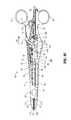
- FIG. 1is a perspective view of a bipolar forceps according to an embodiment of the present disclosure including a mechanical forceps, a disposable housing, and a disposable electrode assembly;
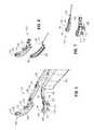
- FIG. 2is an enlarged, perspective view of a distal end of the bipolar forceps of FIG. 1 ;
- FIG. 3is a perspective view of the bipolar forceps of FIG. 1 with parts separated;
- FIG. 4is an enlarged, internal side view of the disposable housing and the disposable electrode assembly of FIG. 1 with parts partially removed;
- FIG. 5is a greatly-enlarged, perspective view of the disposable electrode assembly of FIG. 1 ;
- FIGS. 6 and 7are greatly-enlarged perspective views of electrodes of the disposable electrode assembly of FIG. 1 with parts separated;
- FIG. 8is a perspective view of the bipolar forceps of FIG. 1 grasping tissue to effect a tissue seal
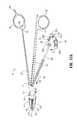
- FIGS. 9A-9Dare generally internal, side views of the bipolar forceps of FIG. 1 depicting a sequence of motions to illustrate operation of the bipolar forceps;
- FIGS. 10A and 10Bare generally internal, side views of a bipolar forceps according to another embodiment of the present disclosure with parts partially removed;
- FIG. 11Ais an enlarged, perspective view of a distal portion of a bipolar forceps according to another embodiment of the present disclosure with parts partially removed;
- FIG. 11Bis an enlarged, cross-sectional distal view of the bipolar forceps of FIG. 11A taken through a central portion of the bipolar forceps.
- a bipolar forceps 10 for use with open surgical proceduresincludes a mechanical forceps 20 having an end effector 24 and a disposable electrode assembly 21 .
- Mechanical forceps 20includes first and second elongated shaft members 12 and 14 .
- Elongated shaft member 12includes proximal and distal end portions 13 and 17 , respectively, and elongated shaft member 14 includes proximal and distal end portions 15 and 19 , respectively.
- Disposed at proximal end portions 13 , 15 of shaft members 12 , 14are handle members 16 and 18 , respectively, that are configured to allow a user to effect movement of at least one of the shaft members 12 and 14 relative to the other.
- the end effector 24includes opposing jaw members 42 , 44 that extend from the distal end portions 17 and 19 of shaft members 12 and 14 , respectively.
- the jaw members 42 , 44are movable relative to each other in response to movement of shaft members 12 , 14 .
- At least one of the shaft members, e.g., shaft member 12includes a tang 99 that facilitates manipulation of forceps 20 during use.
- Shaft members 12 and 14are affixed to one another about a pivot 25 ( FIG. 3 ) such that movement of shaft members 12 , 14 , imparts movement of the jaw members 42 , 44 from an open configuration ( FIG. 9A ) wherein the jaw members 44 , 42 are disposed in spaced relation relative to one another to a clamping or closed configuration ( FIGS. 9B and 9C ) wherein the jaw members 42 , 44 cooperate to grasp tissue 150 therebetween ( FIG. 8 ).
- the forceps 10may be configured such that movement of one or both of the shaft members 12 , 14 causes only one of the jaw members to move with respect to the other jaw member.
- Pivot 25includes a pair of generally semi-circular shaped apertures 25 a , 25 b disposed therethrough and is configured to be seated in a pivot aperture 29 ( FIG. 3 ) such that pivot 25 is permitted to freely rotate within pivot aperture 29 , as further detailed below.
- disposable electrode assembly 21is configured to releasably couple to mechanical forceps 20 , as detailed below, and is operably coupled to a housing 70 having a pair of housing halves 70 a , 70 b configured to matingly engage and releasably encompass at least a portion of shaft member 14 .
- Housing 70also serves to at least partially house a knife 85 having a sharpened distal cutting edge 89 ( FIG. 9D ), a knife guide 86 having a longitudinal slot 87 ( FIG. 3 ) configured to receive the knife blade 85 therein, and a knife actuation mechanism 90 configured to effect advancement of the knife blade 85 through a knife channel 58 ( FIG.
- each of housing halves 70 a , 70 bmay include a plurality of cooperating mechanical interfaces disposed at various locations to effect mechanical coupling of housing halves 70 a , 70 b to form housing 70 .
- a pair of opposing push buttons 75 a , 75 bare disposed on housing halves 70 a , 70 b , respectively, and are accessible from an exterior of housing 70 such that a user may press buttons 75 a , 75 b inwardly relative to the housing 70 to release the mechanical coupling of housing 70 and shaft member 14 .
- a resilient member 64( FIG.
- Resilient member 64includes a pair of resilient extensions 66 a , 66 b that are operably coupled to buttons 75 a , 75 b , respectively. Pressing buttons 75 a , 75 b inwardly relative to housing 70 imparts a biasing force on resilient extensions 66 a , 66 b such that resilient extensions 66 a , 66 b flex inward toward each other, which in turn causes resilient member 64 to release from shaft member 14 . Once resilient member 64 is released from shaft member 14 , housing 70 may be uncoupled from mechanical forceps 20 . Thus, the user is provided with the ability to uncouple housing 70 from mechanical forceps 20 simply by pressing buttons 75 a , 75 b inwardly relative to housing 70 .
- buttons 75 a , 75 bmay be disposed on any suitable location of housing 70 .
- buttons 75 a , 75 bmay be disposed on a proximal end of housing 70 adjacent handle member 18 and proximal to a depressible activation button 50 ( FIG. 1 ) described in detail below.
- buttons 75 a , 75 b and/or resilient member 64may include wire-routing features formed therein for routing wires through housing 70 .
- a pair of wires 61 and 62are electrically connected to the electrodes 120 and 110 , respectively, and are bundled to form a cable 28 that extends through housing 70 and terminates at a terminal connector 30 ( FIG. 1 ) configured to mechanically and electrically couple to a suitable energy source, such as an electrosurgical generator (not shown).
- a suitable energy sourcesuch as an electrosurgical generator (not shown). Examples of electrosurgical generators are the LIGASURE® Vessel Sealing Generator and the ForceTriad® Generator sold by Covidien.
- a suitable energy sourcemay be a battery (not shown) supported by the housing 70 and electrically connected to the electrodes 110 , 120 .
- Electrode 120includes an electrically conductive sealing surface 126 configured to conduct electrosurgical energy therethrough and an electrically insulative substrate 121 that serves to electrically insulate sealing surface 126 from jaw member 44 .
- Sealing surface 126 and substrate 121are attached to one another by any suitable method of assembly such as, for example, snap-fit engagement or by overmolding substrate 121 to sealing surface 126 .
- substrate 121is made from an injection molded plastic material.
- Substrate 121includes a plurality of bifurcated anchor members 122 extending therefrom that are configured to compress inwardly during insertion into a corresponding plurality of sockets 43 disposed at least partially through an inner facing surface 48 ( FIG. 3 ) of jaw member 44 and subsequently expand to releasably engage corresponding sockets 43 after insertion to couple electrode 120 to inner facing surface 48 .
- Substrate 121also includes one or more alignment pins 124 ( FIG. 4 ) that are configured to engage a corresponding aperture 65 disposed at least partially through inner facing surface 48 of jaw member 44 to ensure proper alignment of electrode 120 with jaw member 44 during assembly.
- Conductive sealing surface 126includes an extension 135 having a wire crimp 117 ( FIG. 6 ) configured to be inserted into the distal end 106 of prong 105 of electrode assembly 21 and electrically connect to wire 61 disposed therein ( FIG. 5 ).
- electrode 110includes an electrically conductive sealing surface 116 configured to conduct electrosurgical energy therethrough and an electrically insulative substrate 111 attached thereto, as shown in FIG. 7 .
- Substrate 111includes a plurality of bifurcated anchor members 112 extending therefrom that are configured to compress inwardly during insertion into a corresponding plurality of sockets 41 disposed at least partially through an inner facing surface 46 ( FIG. 3 ) of jaw member 42 and subsequently expand to releasably engage corresponding sockets 41 after insertion to couple electrode 110 to inner facing surface 46 .
- Substrate 111also includes one ore more alignment pins 128 ( FIG.
- Sealing surface 116includes an extension 155 having a wire crimp 119 ( FIG. 7 ) extending therefrom configured to be inserted into the distal end 104 of prong 103 of electrode assembly 21 and electrically connect to wire 62 disposed therein ( FIG. 5 ).
- the electrode assembly 21is removably attached to the mechanical forceps 20 by initially moving prongs 103 , 105 towards each other. While jaw members 42 , 44 are in an open configuration, the electrodes 120 and 110 may be slid between opposing jaw members 44 and 42 such that anchor members 122 and 112 and guide pins 124 and 128 , respectively, may be aligned with and releasably inserted into corresponding sockets 43 and 41 or apertures 65 and 67 , respectively, to couple electrodes 120 and 110 with jaw member 44 and 42 , respectively. Housing halves 70 a , 70 b may then be coupled to form housing 70 to encompass at least a portion of shaft member 14 in the manner described above.
- a depressible activation button 50( FIG. 1 ) extends from a proximal portion of housing 70 and is operable by a user to initiate and terminate the delivery of electrosurgical energy to end effector 24 .
- Mechanically coupled to depressible activation button 50is a switch 36 ( FIG. 4 ) supported within housing 70 and electrically interconnected between wires 61 , 62 and a suitable energy source, such as an electrosurgical generator (not shown).
- Depressible activation button 50is engageable by a button activation post 38 extending from proximal end 13 of shaft member 12 upon movement of shaft members 12 , 14 to an actuated or approximated position ( FIG. 9B ).
- engagement of depressible activation button 50 with button activation post 38serves to activate switch 36 to initiate delivery of electrosurgical energy to end effector 24 for effecting a tissue seal
- disengagement of button activation post 38 from depressible activation button 50serves to deactivate switch 36 to terminate delivery of electrosurgical energy to end effector 24
- delivery of electrosurgical energy to end effector 24may also be terminated by the electrosurgical generator based on any suitable parameters, e.g., sensed tissue properties, time parameters, sensed energy properties, etc.
- the knife blade 85may be advanced through the knife channel 58 to transect the sealed tissue, as detailed below. However, in some embodiments, knife blade 85 may be advanced through the knife channel 58 before, during, or after tissue sealing. In some embodiments, a knife lockout mechanism is provided to prevent extension of the knife blade 85 into the knife channel 58 when the jaw members 42 , 44 are in the open configuration, thus preventing accidental or premature transection of tissue, as described below.
- the knife actuation mechanism 90is operably associated with a trigger 45 ( FIG. 1 ) having opposing handle members 45 a , 45 b extending from opposing sides of housing 70 .
- the housing 70is shaped to complement an outwardly extending cutout portion 14 a of shaft member such that upon coupling of housing halves 70 a , 70 b about shaft member 14 , the knife actuation mechanism 90 is encompassed by the housing 70 ( FIG. 1 ).
- the knife actuation mechanism 90Upon actuation of handle members 45 a , 45 b , the knife actuation mechanism 90 responds utilizing a series of inter-cooperating elements to actuate the knife blade 85 through the knife channel 58 to sever tissue grasped between jaw members 42 , 44 , as detailed below with reference to FIG. 9C .
- the knife actuation mechanism 90includes a first link 92 having an arcuate portion 93 bridging opposing linear extensions 91 a , 91 b and a second link 94 having an arcuate portion 96 bridging opposing linear extensions 98 a , 98 b .
- Arcuate portion 93is operably coupled to a shaft member 47 and linear extensions 91 a , 91 b are operably coupled to linear extensions 98 a , 98 b of second link 94 by opposing pivot pins 92 a , 92 b , respectively.
- Shaft member 47extends laterally through housing 70 to operably connect handle members 45 a , 45 b from opposing sides of housing 70 .
- Arcuate portion 96 of second link 94is operably coupled to a proximal end of the knife blade 85 by a pivot pin 94 a extending through arcuate portion 96 . As can be seen in FIG.
- each of first and second links 92 , 94are generally u-shaped components so that opposing linear extensions 91 a , 91 b and 98 a , 98 b define a space therebetween through which shaft member 14 may pass unimpeded during assembly and during actuation of knife actuation mechanism 90 .
- This generally u-shaped configurationallows first and second links 92 , 94 to extend around shaft member 14 .
- a mechanical interface 72is supported within housing 70 and is disposed between knife actuation mechanism 90 and one of the housing halves (e.g., housing half 70 a ).
- Mechanical interface 72includes a through hole 74 through which shaft member 47 extends and a longitudinal channel 76 through which at least a portion of pivot pin 94 a translates during actuation of knife blade 85 . More specifically, pivot pin 94 a extends outwardly from opposing sides of arcuate portion 96 , as shown in FIG. 3 . At least a portion of pivot pin 94 a that extends outwardly from one opposing side of arcuate portion 96 is received within longitudinal channel 76 . As handle members 45 a , 45 b are moved from an unactuated configuration ( FIGS.
- pivot pin 94 atranslates distally through longitudinal channel 76 from a proximal portion thereof to a distal portion thereof.
- longitudinal channel 76serves to constrain upward and downward movement of pivot pin 94 a , thereby ensuring linear longitudinal motion of knife blade 85 .
- Mechanical interface 72may also serve as a protective cover for wires 61 , 62 as wires pass through housing half 70 a , for example, by separating wires 61 , 62 from knife actuation mechanism 90 such that wires 61 , 62 do not interfere with knife actuation mechanism 90 during actuation thereof.
- Mechanical interface 72also serves to prevent inadvertent actuation of knife actuation mechanism 90 prior to coupling of mechanical forceps 20 to the remaining components of forceps 10 , as described in further detail below.
- a biasing member 95(e.g., a torsion spring) is disposed coaxially about at least a portion of the shaft member 47 ( FIG. 3 ) between the first link 92 and handle member 45 a .
- the biasing member 95is operably coupled at one end to a portion of the first link 92 and at the other end to a suitable mechanical interface within the housing 70 that stabilizes biasing member 95 during use of the knife actuation mechanism 90 .
- the biasing member 95serves to bias the trigger 45 such that subsequent to actuation of the knife blade 85 through the knife channel 58 ( FIG. 9C ), handle members 45 a , 45 b are biased to return to an unactuated position ( FIGS.
- a knife kickback 22is disposed along a portion of shaft member 12 and, upon movement of shaft members 12 , 14 from the closed configuration ( FIG. 9B ) to the open configuration ( FIG. 9A ), knife kickback 22 is configured to engage handle members 45 a , 45 b ( FIG. 9D ) in the event that handle members 45 a , 45 b do not return to an unactuated position ( FIGS. 9A and 9B ) following actuation of the knife actuation mechanism 90 , as detailed below with reference to FIG. 9D .
- pivot 25includes a pair of apertures 25 a , 25 b disposed therethrough that are configured to receive a pair of complementary raised portions 13 a , 13 b therein, respectively, extending from the distal end portion 19 of shaft member 14 and defining a longitudinal passageway 27 therebetween.
- Raised portions 13 a , 13 bextend sufficiently from the distal portion of shaft member 14 so that apertures 25 a , 25 b may receive raised portions 13 a , 13 b therein, respectively, while maintaining pivot 25 in spaced relation with the distal portion of shaft member 14 to allow the knife guide 86 to be received through passageway 27 .
- Movement of shaft members 12 , 14 relative to each othercauses rotational movement of pivot 25 within pivot aperture 29 .
- Knife guide 86is supported within the housing 70 between the end effector 24 and the knife actuation mechanism 90 and extends through passageway 27 .
- Knife guide 86includes suitable mechanical features (e.g., protrusions) that interface with corresponding suitable mechanical features disposed on shaft member 14 to provide upward and downward location control of knife guide 86 .
- the longitudinal slot 87 defined through knife guide 86( FIG. 3 ) provides lateral support to the knife blade 85 and constrains side-to-side lateral motion of the knife blade 85 .
- the knife guide 86serves to urge the knife blade 85 into a central position relative to end effector 24 , thereby ensuring proper alignment of the knife blade 85 as the knife blade 85 enters the knife channel 58 ( FIG. 2 ) defined in electrodes 110 , 120 .
- the forceps 10includes a knife blade lockout mechanism that serves to prevent advancement of the knife blade 85 into the knife channel 85 when the jaw members 42 , 44 are in the open configuration ( FIG. 9A ).
- a knife blade lockout mechanismis shown.
- the knife blade lockout mechanismis pivotally supported within housing 70 ( FIGS. 9A-9D ) and includes a flexible safety link 81 operably coupled about a pivot pin 82 with a biasing member 83 and an engagement member 80 .
- the knife blade 85In the open configuration of jaw members 42 , 44 , the knife blade 85 is in an unactuated position ( FIGS. 9A and 9B ) and the safety link 81 is engaged with the arcuate portion 96 of the second link 94 ( FIG.
- safety link 81is depicted having a t-shaped configuration.
- this t-shaped configurationshould not be construed as limiting, in that safety link 81 may be any shape or configuration suitable to engage and disengage arcuate portion 96 .
- the t-shaped configuration of safety link 81provides load transfer to housing 70 upon actuation of knife actuation mechanism 90 , thereby preventing damage to safety link 81 due to an overload condition.
- a portion of mechanical interface 72is engaged with and in the distal path of the arcuate portion 96 of the second link 94 such that distal advancement of knife blade 85 is prohibited.
- shaft member 14deflects mechanical interface 72 to remove the previously engaged portion of mechanical interface 72 from the distal path of the arcuate portion 96 .
- housing 70includes a longitudinal opening 70 c that opposes shaft member 12 and exposes engagement member 80 such that upon approximation of the shaft members 12 , 14 to move the jaw members 42 , 44 to the closed position ( FIG. 9B ), engagement member 80 is engaged by shaft member 12 .
- Pressure applied to engagement member 80 by shaft member 12 through approximation of shaft members 12 , 14induces counter clockwise rotation of engagement member 80 and biasing member 83 about pivot pin 82 (as depicted by rotational arrow A 3 in FIG.
- the tissue seal thickness and tissue seal effectivenessmay be influenced by the pressure applied to tissue between jaw members 44 , 42 and the gap distance between the opposing electrodes 110 and 120 ( FIG. 5 ) during tissue sealing.
- a separation or gap distance “G”may be maintained between the sealing surfaces 116 , 126 by an array of stop members 54 ( FIG. 2 ) disposed on one or both of sealing surfaces 116 , 126 (only shown disposed on sealing surface 126 for purposes of illustration).
- the stop members 54contact the sealing surface on the opposing jaw member and prohibit further approximation of the sealing surfaces 116 , 126 .
- an appropriate gap distance of about 0.001 inches to about 0.010 inches and, desirably, between about 0.002 and about 0.005 inchesmay be provided.
- the stop members 54are constructed of an electrically non-conductive plastic or other material molded onto the sealing surfaces 116 , 126 , e.g., by a process such as overmolding or injection molding. In other embodiments, the stop members 54 are constructed of a heat-resistant ceramic deposited onto sealing surfaces 116 , 126 .
- FIG. 8shows the bipolar forceps 10 during use wherein the shaft members 12 and 14 are approximated to apply clamping force to tissue 150 and to effect a tissue seal. Once sealed, tissue 150 may be cut along the tissue seal through actuation of the knife blade 85 , as detailed below with reference to FIG. 9C .
- a sequence of motionsmay be initiated by moving the shaft members 12 , 14 in order to close the jaw members 42 , 44 , and by actuating the handle members 45 a , 45 b to induce the knife actuation mechanism 90 to translate the knife blade 85 through the knife channel 58 .
- shaft members 12 , 14are in the open configuration and the handle members 45 a , 45 b are in an unactuated configuration as depicted in FIG. 9A .
- safety link 81is engaged with arcuate portion 96 of second link 94 such that rotational motion of the handle members 45 a , 45 b in a proximal direction (depicted by rotational arrow A 4 in FIG. 9C ) is prohibited so that knife blade 85 is prohibited from advancing into knife channel 58 .
- the jaw members 42 , 44may be moved from the open configuration of FIG. 9A to the closed configuration depicted in FIG. 9B .
- shaft member 12engages engagement member 80 and button activation post 38 engages button 50 .
- shaft 12engages engagement member 80 simultaneously with button activation post 38 engaging button 50 .
- button activation post 38depresses activation button 50 to initiate delivery of electrosurgical energy to end effector 24 and shaft 12 applies pressure on the engagement member 80 .
- handle members 45 a , 45 bmay be selectively moved from the unactuated configuration of FIGS. 9A and 9B to the actuated configuration of FIG. 9C to advance the knife blade 85 distally through knife channel 58 . More specifically, as handle members 45 a , 45 b rotate in the general proximal direction, as depicted by rotational arrow A 4 in FIG. 9C , the first link 92 imparts a rotational force on second link 94 , thereby causing second link 94 to rotate about pivot pin 94 a and translate pivot pin 94 a distally through longitudinal channel 76 to advance knife blade 85 distally into the knife channel 58 .
- FIGS. 9A and 9Bthe initial position of the handles 45 a , 45 b depicted in FIGS. 9A and 9B is actively maintained by the influence of the biasing member 95 on the trigger 45 .
- FIG. 9Din the event that handles 45 a , 45 b fail to return to their initial position ( FIGS. 9A and 9B ) following movement to the actuated configuration ( FIG. 9C ), movement of the shaft members 12 , 14 to the open configuration serves as a fail-safe to return handles 45 a , 45 b to the unactuated configuration ( FIGS. 9A and 9B ).
- knife kickback 22engages handles 45 a , 45 b such that handles 45 a , 45 b are forced in the general distal direction, depicted by rotational arrow A 5 in FIG. 9D , to the unactuated configuration depicted in FIGS. 9A and 9B .
- shaft members 12 , 14are configured such that upon affixing of shaft members 12 , 14 to each other about pivot 25 , shaft member 14 is disposed at an angle relative to shaft member 12 that is substantially different than the angle depicted by the embodiment of FIGS. 9A-9D .
- knife guide 86may be inserted into passageway 27 of pivot 25 from an exterior side of shaft member 14 , as depicted by directional arrow B 2 .
- the knife actuation assembly 90may be moved toward shaft member 14 and, upon suitable placement of knife actuation assembly 90 relative to shaft member 14 , housing 70 (removed from FIGS. 10A and 10B for clarity) may be releasably coupled to shaft member 14 to at least partially house knife 85 , knife guide 86 , and knife actuation mechanism 90 substantially as described above with respect to FIGS. 2 and 3 .
- the ability to assemble forceps 10 in the manner described above with respect to FIGS. 10A and 10Bconveniently allows forceps 10 to be assembled in the sterile field and/or the operating theater before or during a medical procedure.
- shaft member 14forms a pair of opposing guide rails 23 a , 23 b extending along a distal portion thereof.
- housing 70forms a pair of opposing guide channels 71 a , 71 b that are configured to capture guide rails 23 a , 23 b therein, respectively.
- housing 70may be moved relative to shaft member 14 such that guide rails 23 a , 23 b slide within guide channels 71 a , 71 b , respectively, to ensure proper placement of housing 70 relative to shaft member 14 .
- guide rails 23 a , 23 bmay be formed between approximately a middle portion of shaft member 14 to distal end 19 of shaft member 14 .
- Guide channels 71 , 71 bmay be aligned with a proximal end of guide rails 23 a , 23 b , respectively, at the middle portion of shaft member 14 .
- Housing 70may then be pushed distally along shaft member 14 so that guide rails 23 a , 23 b slide within guide channels 71 a , 71 b to ensure proper placement of housing 70 relative to shaft member 14 .
Landscapes
- Health & Medical Sciences (AREA)
- Surgery (AREA)
- Life Sciences & Earth Sciences (AREA)
- Engineering & Computer Science (AREA)
- Heart & Thoracic Surgery (AREA)
- Animal Behavior & Ethology (AREA)
- Veterinary Medicine (AREA)
- Biomedical Technology (AREA)
- Nuclear Medicine, Radiotherapy & Molecular Imaging (AREA)
- Medical Informatics (AREA)
- Molecular Biology (AREA)
- Public Health (AREA)
- General Health & Medical Sciences (AREA)
- Physics & Mathematics (AREA)
- Plasma & Fusion (AREA)
- Otolaryngology (AREA)
- Pathology (AREA)
- Oral & Maxillofacial Surgery (AREA)
- Surgical Instruments (AREA)
Abstract
Description
Claims (18)
Applications Claiming Priority (1)
| Application Number | Priority Date | Filing Date | Title |
|---|---|---|---|
| PCT/CN2013/080947WO2015017991A1 (en) | 2013-08-07 | 2013-08-07 | Bipolar surgical instrument |
Related Parent Applications (1)
| Application Number | Title | Priority Date | Filing Date |
|---|---|---|---|
| PCT/CN2013/080947A-371-Of-InternationalWO2015017991A1 (en) | 2013-08-07 | 2013-08-07 | Bipolar surgical instrument |
Related Child Applications (1)
| Application Number | Title | Priority Date | Filing Date |
|---|---|---|---|
| US15/961,461ContinuationUS10959770B2 (en) | 2013-08-07 | 2018-04-24 | Method of assembling an electrosurgical instrument |
Publications (2)
| Publication Number | Publication Date |
|---|---|
| US20160157922A1 US20160157922A1 (en) | 2016-06-09 |
| US9962221B2true US9962221B2 (en) | 2018-05-08 |
Family
ID=52460495
Family Applications (3)
| Application Number | Title | Priority Date | Filing Date |
|---|---|---|---|
| US14/906,072ActiveUS9962221B2 (en) | 2013-08-07 | 2013-08-07 | Bipolar surgical instrument |
| US15/961,461Active2034-03-29US10959770B2 (en) | 2013-08-07 | 2018-04-24 | Method of assembling an electrosurgical instrument |
| US17/215,844Active2033-12-20US11826090B2 (en) | 2013-08-07 | 2021-03-29 | Bipolar surgical instrument |
Family Applications After (2)
| Application Number | Title | Priority Date | Filing Date |
|---|---|---|---|
| US15/961,461Active2034-03-29US10959770B2 (en) | 2013-08-07 | 2018-04-24 | Method of assembling an electrosurgical instrument |
| US17/215,844Active2033-12-20US11826090B2 (en) | 2013-08-07 | 2021-03-29 | Bipolar surgical instrument |
Country Status (8)
| Country | Link |
|---|---|
| US (3) | US9962221B2 (en) |
| EP (2) | EP3030178B1 (en) |
| JP (1) | JP6099231B2 (en) |
| KR (1) | KR102134566B1 (en) |
| CN (1) | CN105640640B (en) |
| AU (3) | AU2013375909B2 (en) |
| BR (1) | BR112016001520A8 (en) |
| WO (1) | WO2015017991A1 (en) |
Cited By (4)
| Publication number | Priority date | Publication date | Assignee | Title |
|---|---|---|---|---|
| US20190167341A1 (en)* | 2010-10-04 | 2019-06-06 | Covidien Lp | Vessel sealing instrument |
| USD911523S1 (en)* | 2016-03-09 | 2021-02-23 | Covidien Lp | L-shaped blade trigger for an electrosurgical instrument |
| US10959770B2 (en) | 2013-08-07 | 2021-03-30 | Covidien Lp | Method of assembling an electrosurgical instrument |
| US12402934B2 (en) | 2019-09-15 | 2025-09-02 | Covidien Lp | Electrosurgical instrument for grasping, treating, and/or dividing tissue incorporating thermal management feature |
Families Citing this family (24)
| Publication number | Priority date | Publication date | Assignee | Title |
|---|---|---|---|---|
| US9468454B2 (en)* | 2014-01-28 | 2016-10-18 | Ethicon Endo-Surgery, Inc. | Motor control and feedback in powered surgical devices |
| US9987078B2 (en)* | 2015-07-22 | 2018-06-05 | Covidien Lp | Surgical forceps |
| JP7102409B2 (en)* | 2016-12-21 | 2022-07-19 | エシコン エルエルシー | Shaft assembly with manually operable retracting system for use with motorized surgical instrument systems |
| US11172980B2 (en) | 2017-05-12 | 2021-11-16 | Covidien Lp | Electrosurgical forceps for grasping, treating, and/or dividing tissue |
| US10973567B2 (en)* | 2017-05-12 | 2021-04-13 | Covidien Lp | Electrosurgical forceps for grasping, treating, and/or dividing tissue |
| US10653475B2 (en)* | 2017-06-08 | 2020-05-19 | Covidien Lp | Knife lockout for electrosurgical forceps |
| USD904611S1 (en) | 2018-10-10 | 2020-12-08 | Bolder Surgical, Llc | Jaw design for a surgical instrument |
| US11376062B2 (en) | 2018-10-12 | 2022-07-05 | Covidien Lp | Electrosurgical forceps |
| US11471211B2 (en) | 2018-10-12 | 2022-10-18 | Covidien Lp | Electrosurgical forceps |
| US20210338312A1 (en)* | 2018-10-19 | 2021-11-04 | Conmed Corporation | Scissor style vessel sealer |
| US11350982B2 (en) | 2018-12-05 | 2022-06-07 | Covidien Lp | Electrosurgical forceps |
| US11304743B2 (en)* | 2019-01-30 | 2022-04-19 | Covidien Lp | Electrosurgical forceps |
| US11510725B2 (en)* | 2019-01-30 | 2022-11-29 | Covidien Lp | Electrosurgical forceps |
| US11523861B2 (en) | 2019-03-22 | 2022-12-13 | Covidien Lp | Methods for manufacturing a jaw assembly for an electrosurgical forceps |
| US11622804B2 (en) | 2020-03-16 | 2023-04-11 | Covidien Lp | Forceps with linear trigger mechanism |
| US12295641B2 (en) | 2020-07-01 | 2025-05-13 | Covidien Lp | Electrosurgical forceps with swivel action nerve probe |
| USD934423S1 (en) | 2020-09-11 | 2021-10-26 | Bolder Surgical, Llc | End effector for a surgical device |
| EP4000541B1 (en)* | 2020-11-12 | 2023-05-03 | Erbe Elektromedizin GmbH | Surgical instrument |
| CN112674862A (en)* | 2020-12-22 | 2021-04-20 | 杭州桐庐医达器械设备有限公司 | Ball head structure of bipolar scissors |
| CN112932656A (en)* | 2021-02-03 | 2021-06-11 | 南京艾力芬医疗器械有限公司 | Wireless open type tissue closed cutting forceps for electrosurgery and system thereof |
| USD1046129S1 (en) | 2021-04-14 | 2024-10-08 | Bolder Surgical, Llc | End effector for a surgical instrument |
| DE102022100924A1 (en)* | 2022-01-17 | 2023-07-20 | Aesculap Ag | Caiman Ring Forceps - Manual HF activation |
| CN115607267B (en)* | 2022-10-21 | 2024-03-29 | 南京首量医疗科技有限公司 | Reusable high-frequency electrosurgical closer |
| CN116549039A (en)* | 2023-02-02 | 2023-08-08 | 江苏风和医疗器材股份有限公司 | surgical instruments |
Citations (178)
| Publication number | Priority date | Publication date | Assignee | Title |
|---|---|---|---|---|
| SU401367A1 (en) | 1971-10-05 | 1973-10-12 | Тернопольский государственный медицинский институт | BIAKTIVNYE ELECTRO SURGICAL INSTRUMENT |
| DE2415263A1 (en) | 1974-03-29 | 1975-10-02 | Aesculap Werke Ag | Surgical H.F. coagulation probe has electrode tongs - with exposed ends of insulated conductors forming tong-jaws |
| DE2514501A1 (en) | 1975-04-03 | 1976-10-21 | Karl Storz | Bipolar coagulation instrument for endoscopes - has two high frequency electrodes looped over central insulating piece |
| DE2627679A1 (en) | 1975-06-26 | 1977-01-13 | Marcel Lamidey | HEMATISTIC HIGH FREQUENCY EXTRACTOR FORCEPS |
| USD249549S (en) | 1976-10-22 | 1978-09-19 | Aspen Laboratories, Inc. | Electrosurgical handle |
| USD263020S (en) | 1980-01-22 | 1982-02-16 | Rau Iii David M | Retractable knife |
| JPS61501068A (en) | 1984-01-30 | 1986-05-29 | ハルコフスキイ ナウチノ−イススレドワテルスキイ インスチチユ−ト オブスチエイ イ ネオトロジノイ ヒルルギイ | bipolar electrosurgical instrument |
| DE3423356C2 (en) | 1984-06-25 | 1986-06-26 | Berchtold Medizin-Elektronik GmbH & Co, 7200 Tuttlingen | Electrosurgical high frequency cutting instrument |
| DE3612646A1 (en) | 1985-04-16 | 1987-04-30 | Ellman International | Electrosurgical handle piece for blades, needles and forceps |
| DE8712328U1 (en) | 1987-09-11 | 1988-02-18 | Jakoubek, Franz, 7201 Emmingen-Liptingen | Endoscopy forceps |
| USD295893S (en) | 1985-09-25 | 1988-05-24 | Acme United Corporation | Disposable surgical clamp |
| USD295894S (en) | 1985-09-26 | 1988-05-24 | Acme United Corporation | Disposable surgical scissors |
| USD298353S (en) | 1986-05-06 | 1988-11-01 | Vitalmetrics, Inc. | Handle for surgical instrument |
| USD299413S (en) | 1985-07-17 | 1989-01-17 | The Stanley Works | Folding pocket saw handle |
| JPS6424051A (en) | 1987-07-16 | 1989-01-26 | Meisho Koki Kk | Sheet glass having transparency pattern and its production |
| JPH01147150A (en) | 1987-12-04 | 1989-06-08 | Hitachi Ltd | Variable venturi carburetor |
| US5100420A (en) | 1989-07-18 | 1992-03-31 | United States Surgical Corporation | Apparatus and method for applying surgical clips in laparoscopic or endoscopic procedures |
| JPH04502328A (en) | 1988-12-05 | 1992-04-23 | ザ・トラステイーズ・オブ・コロンビア・ユニヴアーシテイ・イン・ザ・シテイ・オブ・ニユー・ヨーク | Novel derivative of cyclosporin A, antibodies against it and uses thereof |
| JPH055106A (en) | 1990-07-31 | 1993-01-14 | Matsushita Electric Works Ltd | Production of alloy sintered body |
| JPH0540112A (en) | 1991-02-08 | 1993-02-19 | Tokico Ltd | Sample liquid component analyzer |
| WO1994000059A1 (en) | 1992-06-24 | 1994-01-06 | Microsurge, Inc. | Reusable endoscopic surgical instrument |
| USD343453S (en) | 1993-05-05 | 1994-01-18 | Laparomed Corporation | Handle for laparoscopic surgical instrument |
| US5304203A (en) | 1992-10-20 | 1994-04-19 | Numed Technologies, Inc. | Tissue extracting forceps for laparoscopic surgery |
| JPH06121797A (en) | 1992-02-27 | 1994-05-06 | United States Surgical Corp | Equipment and method for performing intracutaneous stapling of body tissue |
| USD348930S (en) | 1991-10-11 | 1994-07-19 | Ethicon, Inc. | Endoscopic stapler |
| USD349341S (en) | 1992-10-28 | 1994-08-02 | Microsurge, Inc. | Endoscopic grasper |
| JPH06285078A (en) | 1993-04-05 | 1994-10-11 | Olympus Optical Co Ltd | Forceps |
| JPH06343644A (en) | 1993-05-04 | 1994-12-20 | Gyrus Medical Ltd | Surgical peritoneoscope equipment |
| JPH06511401A (en) | 1991-06-07 | 1994-12-22 | バイタル メディカル プロダクツ コーポレイション | Bipolar electrosurgical endoscopic instrument and its method of use |
| USD354564S (en) | 1993-06-25 | 1995-01-17 | Richard-Allan Medical Industries, Inc. | Surgical clip applier |
| DE4303882C2 (en) | 1993-02-10 | 1995-02-09 | Kernforschungsz Karlsruhe | Combination instrument for separation and coagulation for minimally invasive surgery |
| USD358887S (en) | 1993-12-02 | 1995-05-30 | Cobot Medical Corporation | Combined cutting and coagulating forceps |
| DE4403252A1 (en) | 1994-02-03 | 1995-08-10 | Michael Hauser | Instrument shaft for min. invasive surgery |
| JPH07265328A (en) | 1993-11-01 | 1995-10-17 | Gyrus Medical Ltd | Electrode assembly for electric surgery device and electric surgery device using it |
| JPH0856955A (en) | 1994-06-29 | 1996-03-05 | Gyrus Medical Ltd | Electric surgical apparatus |
| DE19515914C1 (en) | 1995-05-02 | 1996-07-25 | Aesculap Ag | Tong or scissor-shaped surgical instrument |
| DE19506363A1 (en) | 1995-02-24 | 1996-08-29 | Frost Lore Geb Haupt | Non-invasive thermometry in organs under hyperthermia and coagulation conditions |
| JPH08252263A (en) | 1994-12-21 | 1996-10-01 | Gyrus Medical Ltd | Electronic surgical incision instrument and electronic surgical incision device using the same |
| DE29616210U1 (en) | 1996-09-18 | 1996-11-14 | Olympus Winter & Ibe Gmbh, 22045 Hamburg | Handle for surgical instruments |
| US5578052A (en) | 1992-10-27 | 1996-11-26 | Koros; Tibor | Insulated laparoscopic grasper with removable shaft |
| JPH08317934A (en) | 1995-04-12 | 1996-12-03 | Ethicon Endo Surgery Inc | Hemostatic device for electric surgery with adaptable electrode |
| JPH0910223A (en) | 1995-06-23 | 1997-01-14 | Gyrus Medical Ltd | Generator and system for electric operation |
| US5618294A (en) | 1994-05-24 | 1997-04-08 | Aust & Taylor Medical Corporation | Surgical instrument |
| DE19608716C1 (en) | 1996-03-06 | 1997-04-17 | Aesculap Ag | Bipolar surgical holding instrument |
| JPH09122138A (en) | 1995-10-20 | 1997-05-13 | Ethicon Endo Surgery Inc | Apparatus for operation |
| US5665100A (en) | 1989-12-05 | 1997-09-09 | Yoon; Inbae | Multifunctional instrument with interchangeable operating units for performing endoscopic procedures |
| USD384413S (en) | 1994-10-07 | 1997-09-30 | United States Surgical Corporation | Endoscopic suturing instrument |
| JPH1024051A (en) | 1995-09-20 | 1998-01-27 | Olympus Optical Co Ltd | Coagulation forceps with separating function |
| DE19751106A1 (en) | 1996-11-27 | 1998-05-28 | Eastman Kodak Co | Laser printer with array of laser diodes |
| JPH10155798A (en) | 1996-12-04 | 1998-06-16 | Asahi Optical Co Ltd | Hot biopsy forceps for endoscopes |
| USH1745H (en) | 1995-09-29 | 1998-08-04 | Paraschac; Joseph F. | Electrosurgical clamping device with insulation limited bipolar electrode |
| US5814043A (en) | 1996-09-06 | 1998-09-29 | Mentor Ophthalmics, Inc. | Bipolar electrosurgical device |
| USD402028S (en) | 1997-10-10 | 1998-12-01 | Invasatec, Inc. | Hand controller for medical system |
| JPH1147150A (en) | 1997-08-06 | 1999-02-23 | Olympus Optical Co Ltd | Endoscopic surgery appliance |
| JPH1170124A (en) | 1997-05-14 | 1999-03-16 | Ethicon Endo Surgery Inc | Improved electrosurgical hemostatic apparatus having anvil |
| USD408018S (en) | 1996-03-12 | 1999-04-13 | Mcnaughton Patrick J | Switch guard |
| DE19751108A1 (en) | 1997-11-18 | 1999-05-20 | Beger Frank Michael Dipl Desig | Electrosurgical operation tool, especially for diathermy |
| WO1999023933A2 (en) | 1997-11-12 | 1999-05-20 | Valleylab, Inc. | Bipolar electrosurgical instrument with replaceable electrodes |
| JPH11169381A (en) | 1997-12-15 | 1999-06-29 | Olympus Optical Co Ltd | High frequency treating device |
| JPH11192238A (en) | 1997-10-10 | 1999-07-21 | Ethicon Endo Surgery Inc | Ultrasonic forceps coagulation device improved of pivot-attaching of forceps arm |
| JPH11244298A (en) | 1997-12-19 | 1999-09-14 | Gyrus Medical Ltd | Electric surgical instrument |
| USD416089S (en) | 1996-04-08 | 1999-11-02 | Richard-Allan Medical Industries, Inc. | Endoscopic linear stapling and dividing surgical instrument |
| JP2000102545A (en) | 1997-06-18 | 2000-04-11 | Eggers & Associates Inc | Electric tweezers for surgery |
| WO2000024330A1 (en) | 1998-10-23 | 2000-05-04 | Sherwood Services Ag | Open vessel sealing forceps with disposable electrodes |
| USD424694S (en) | 1998-10-23 | 2000-05-09 | Sherwood Services Ag | Forceps |
| USD425201S (en) | 1998-10-23 | 2000-05-16 | Sherwood Services Ag | Disposable electrode assembly |
| WO2000036986A1 (en) | 1998-12-18 | 2000-06-29 | Karl Storz Gmbh & Co. Kg | Bipolar medical instrument |
| USH1904H (en) | 1997-05-14 | 2000-10-03 | Ethicon Endo-Surgery, Inc. | Electrosurgical hemostatic method and device |
| JP2000342599A (en) | 1999-05-21 | 2000-12-12 | Gyrus Medical Ltd | Generator for electrosurgical operation, electrosurgical operation system, method for operating this system and method for performing amputation and resection of tissue by electrosurgical operation |
| JP2000350732A (en) | 1999-05-21 | 2000-12-19 | Gyrus Medical Ltd | Electrosurgical system, generator for electrosurgery, and method for cutting or excising tissue by electrosurgery |
| JP2001008944A (en) | 1999-05-28 | 2001-01-16 | Gyrus Medical Ltd | Electric surgical signal generator and electric surgical system |
| JP2001029356A (en) | 1999-06-11 | 2001-02-06 | Gyrus Medical Ltd | Electric and surgical signal generator |
| WO2001015614A1 (en) | 1999-08-27 | 2001-03-08 | Karl Storz Gmbh & Co. Kg | Bipolar medical instrument |
| JP2001128990A (en) | 1999-05-28 | 2001-05-15 | Gyrus Medical Ltd | Electro surgical instrument and electrosurgical tool converter |
| JP2001190564A (en) | 2000-01-12 | 2001-07-17 | Olympus Optical Co Ltd | Medical treatment instrument |
| WO2001054604A1 (en) | 2000-01-25 | 2001-08-02 | Aesculap Ag & Co. Kg | Bipolar gripping device |
| US6277117B1 (en)* | 1998-10-23 | 2001-08-21 | Sherwood Services Ag | Open vessel sealing forceps with disposable electrodes |
| US6293954B1 (en) | 1999-06-21 | 2001-09-25 | Novare Surgical Systems, Inc. | Surgical clamp with replaceable clamp members |
| USD449886S1 (en) | 1998-10-23 | 2001-10-30 | Sherwood Services Ag | Forceps with disposable electrode |
| EP1159926A2 (en) | 2000-06-03 | 2001-12-05 | Aesculap Ag | Scissor- or forceps-like surgical instrument |
| US6329778B1 (en) | 1996-08-15 | 2001-12-11 | Stryker Corporation | Integrated system for powered surgical tools |
| US6334861B1 (en) | 1997-09-10 | 2002-01-01 | Sherwood Services Ag | Biopolar instrument for vessel sealing |
| US6346106B1 (en)* | 1999-08-23 | 2002-02-12 | Geza J Jako | Instrument and method employing snare electrode windable about rotatable spool for minimally invasive electrosurgical resection |
| USD453923S1 (en) | 2000-11-16 | 2002-02-26 | Carling Technologies, Inc. | Electrical rocker switch guard |
| USD454951S1 (en) | 2001-02-27 | 2002-03-26 | Visionary Biomedical, Inc. | Steerable catheter |
| USD457959S1 (en) | 2001-04-06 | 2002-05-28 | Sherwood Services Ag | Vessel sealer |
| USD457958S1 (en) | 2001-04-06 | 2002-05-28 | Sherwood Services Ag | Vessel sealer and divider |
| US6406485B1 (en) | 1999-10-08 | 2002-06-18 | Pilling Weck Incorporated | Surgical grasping device and components thereof |
| WO2002080793A1 (en) | 2001-04-06 | 2002-10-17 | Sherwood Services Ag | Vessel sealing forceps with disposable electrodes |
| WO2002080786A1 (en) | 2001-04-06 | 2002-10-17 | Sherwood Services Ag | Electrosurgical instrument which reduces collateral damage to adjacent tissue |
| DE10045375C2 (en) | 2000-09-14 | 2002-10-24 | Aesculap Ag & Co Kg | Medical instrument |
| USD465281S1 (en) | 1999-09-21 | 2002-11-05 | Karl Storz Gmbh & Co. Kg | Endoscopic medical instrument |
| USD466209S1 (en) | 2001-02-27 | 2002-11-26 | Visionary Biomedical, Inc. | Steerable catheter |
| US20030018332A1 (en) | 2001-06-20 | 2003-01-23 | Schmaltz Dale Francis | Bipolar electrosurgical instrument with replaceable electrodes |
| US6511480B1 (en) | 1998-10-23 | 2003-01-28 | Sherwood Services Ag | Open vessel sealing forceps with disposable electrodes |
| US20030109875A1 (en) | 1999-10-22 | 2003-06-12 | Tetzlaff Philip M. | Open vessel sealing forceps with disposable electrodes |
| US20030199869A1 (en) | 1998-10-23 | 2003-10-23 | Johnson Kristin D. | Vessel sealing instrument |
| US20030208196A1 (en)* | 2002-05-03 | 2003-11-06 | Arthrocare Corporation | Control system for limited-use device |
| US20030229344A1 (en) | 2002-01-22 | 2003-12-11 | Dycus Sean T. | Vessel sealer and divider and method of manufacturing same |
| US6673092B1 (en) | 1998-07-25 | 2004-01-06 | Karl Storz Gmbh & Co. Kg | Medical forceps with two independently moveable jaw parts |
| US20040092927A1 (en) | 2002-11-05 | 2004-05-13 | Podhajsky Ronald J. | Electrosurgical pencil having a single button variable control |
| JP2004517668A (en) | 2000-10-20 | 2004-06-17 | オーナックス・メディカル・インコーポレーテッド | Surgical suturing instrument and method of use |
| USD493888S1 (en) | 2003-02-04 | 2004-08-03 | Sherwood Services Ag | Electrosurgical pencil with pistol grip |
| JP2004528869A (en) | 2001-01-26 | 2004-09-24 | エシコン・エンド−サージェリィ・インコーポレイテッド | Electrosurgical instruments for coagulation and cutting |
| USD496997S1 (en) | 2003-05-15 | 2004-10-05 | Sherwood Services Ag | Vessel sealer and divider |
| USD499181S1 (en) | 2003-05-15 | 2004-11-30 | Sherwood Services Ag | Handle for a vessel sealer and divider |
| US20050004559A1 (en)* | 2003-06-03 | 2005-01-06 | Senorx, Inc. | Universal medical device control console |
| USD502994S1 (en) | 2003-05-21 | 2005-03-15 | Blake, Iii Joseph W | Repeating multi-clip applier |
| US20050107784A1 (en) | 2003-11-19 | 2005-05-19 | Moses Michael C. | Open vessel sealing instrument with cutting mechanism and distal lockout |
| US20050113826A1 (en) | 2002-10-04 | 2005-05-26 | Johnson Kristin D. | Vessel sealing instrument with electrical cutting mechanism |
| US20050113828A1 (en) | 2003-11-20 | 2005-05-26 | Chelsea Shields | Electrically conductive/insulative over-shoe for tissue fusion |
| JP2005144193A (en) | 2003-11-19 | 2005-06-09 | Sherwood Services Ag | Blood vessel sealing instrument for open operation with cutting mechanism |
| US20050159745A1 (en) | 2004-01-16 | 2005-07-21 | Surgrx, Inc. | Electrosurgical instrument with replaceable cartridge |
| USD509297S1 (en) | 2003-10-17 | 2005-09-06 | Tyco Healthcare Group, Lp | Surgical instrument |
| WO2005110264A2 (en) | 2004-05-14 | 2005-11-24 | Erbe Elektromedizin Gmbh | Electrosurgical instrument |
| USD525361S1 (en) | 2004-10-06 | 2006-07-18 | Sherwood Services Ag | Hemostat style elongated dissecting and dividing instrument |
| US7118570B2 (en) | 2001-04-06 | 2006-10-10 | Sherwood Services Ag | Vessel sealing forceps with disposable electrodes |
| USD531311S1 (en) | 2004-10-06 | 2006-10-31 | Sherwood Services Ag | Pistol grip style elongated dissecting and dividing instrument |
| US20060253126A1 (en) | 2005-05-04 | 2006-11-09 | Bernard Medical, Llc | Endoluminal suturing device and method |
| USD533274S1 (en) | 2004-10-12 | 2006-12-05 | Allegiance Corporation | Handle for surgical suction-irrigation device |
| USD533942S1 (en) | 2004-06-30 | 2006-12-19 | Sherwood Services Ag | Open vessel sealer with mechanical cutter |
| USD535027S1 (en) | 2004-10-06 | 2007-01-09 | Sherwood Services Ag | Low profile vessel sealing and cutting mechanism |
| USD538932S1 (en) | 2005-06-30 | 2007-03-20 | Medical Action Industries Inc. | Surgical needle holder |
| USD541418S1 (en) | 2004-10-06 | 2007-04-24 | Sherwood Services Ag | Lung sealing device |
| USD541938S1 (en) | 2004-04-09 | 2007-05-01 | Sherwood Services Ag | Open vessel sealer with mechanical cutter |
| USD541611S1 (en) | 2006-01-26 | 2007-05-01 | Robert Bosch Gmbh | Cordless screwdriver |
| USD545432S1 (en) | 2003-08-08 | 2007-06-26 | Olympus Corporation | Distal portion of hemostatic forceps for endoscope |
| USD547154S1 (en) | 2006-09-08 | 2007-07-24 | Winsource Industries Limited | Rotary driving tool |
| DE202007009317U1 (en) | 2007-06-26 | 2007-08-30 | Aesculap Ag & Co. Kg | Surgical instrument |
| DE202007009165U1 (en) | 2007-06-29 | 2007-08-30 | Kls Martin Gmbh + Co. Kg | Surgical instrument e.g. tube shaft, for use in e.g. high frequency coagulation instrument, has separator inserted through opening such that largest extension of opening transverse to moving direction corresponds to dimension of separator |
| US20070260241A1 (en) | 2006-05-04 | 2007-11-08 | Sherwood Services Ag | Open vessel sealing forceps disposable handswitch |
| DE202007016233U1 (en) | 2007-11-20 | 2008-01-31 | Aesculap Ag & Co. Kg | Surgical forceps |
| US7329257B2 (en) | 1999-01-25 | 2008-02-12 | Olympus Optical Co., Ltd. | Medical treatment instrument |
| USD564662S1 (en) | 2004-10-13 | 2008-03-18 | Sherwood Services Ag | Hourglass-shaped knife for electrosurgical forceps |
| USD567943S1 (en) | 2004-10-08 | 2008-04-29 | Sherwood Services Ag | Over-ratchet safety for a vessel sealing instrument |
| USD575395S1 (en) | 2007-02-15 | 2008-08-19 | Tyco Healthcare Group Lp | Hemostat style elongated dissecting and dividing instrument |
| USD575401S1 (en) | 2007-06-12 | 2008-08-19 | Tyco Healthcare Group Lp | Vessel sealer |
| US20080215048A1 (en) | 2005-10-04 | 2008-09-04 | Dieter Hafner | Electrosurgical Instrument |
| US7431730B2 (en) | 2002-05-10 | 2008-10-07 | Tyco Healthcare Group Lp | Surgical stapling apparatus having a wound closure material applicator assembly |
| USD582038S1 (en) | 2004-10-13 | 2008-12-02 | Medtronic, Inc. | Transurethral needle ablation device |
| DE19738457B4 (en) | 1997-09-03 | 2009-01-02 | Celon Ag Medical Instruments | Method and device for in vivo deep coagulation of biological tissue volumes while sparing the tissue surface with high frequency alternating current |
| US20090082766A1 (en)* | 2007-09-20 | 2009-03-26 | Tyco Healthcare Group Lp | Tissue Sealer and End Effector Assembly and Method of Manufacturing Same |
| US20090131934A1 (en) | 2005-03-31 | 2009-05-21 | Covidion Ag | Electrosurgical Forceps with Slow Closure Sealing Plates and Method of Sealing Tissue |
| US20090182327A1 (en) | 2006-01-24 | 2009-07-16 | Tyco Healthcare Group Lp | Endoscopic Vessel Sealer and Divider for Large Tissue Structures |
| DE102008018406B3 (en) | 2008-04-10 | 2009-07-23 | Bowa-Electronic Gmbh & Co. Kg | Electrosurgical device |
| CN201299462Y (en) | 2008-10-28 | 2009-09-02 | 宋洪海 | Multi-layer metal composite pot |
| US20090240246A1 (en) | 2008-03-19 | 2009-09-24 | Derek Dee Deville | Cordless Medical Cauterization and Cutting Device |
| US20100016857A1 (en) | 2008-07-21 | 2010-01-21 | Mckenna Nicole | Variable Resistor Jaw |
| US20100130977A1 (en) | 2005-08-19 | 2010-05-27 | Covidien Ag | Single Action Tissue Sealer |
| USD617901S1 (en) | 2009-05-13 | 2010-06-15 | Tyco Healthcare Group Lp | End effector chamfered tip |
| USD617903S1 (en) | 2009-05-13 | 2010-06-15 | Tyco Healthcare Group Lp | End effector pointed tip |
| USD617902S1 (en) | 2009-05-13 | 2010-06-15 | Tyco Healthcare Group Lp | End effector tip with undercut top jaw |
| USD617900S1 (en) | 2009-05-13 | 2010-06-15 | Tyco Healthcare Group Lp | End effector tip with undercut bottom jaw |
| USD618798S1 (en) | 2009-05-13 | 2010-06-29 | Tyco Healthcare Group Lp | Vessel sealing jaw seal plate |
| USD621503S1 (en) | 2009-04-28 | 2010-08-10 | Tyco Healthcare Group Ip | Pistol grip laparoscopic sealing and dissection device |
| US20100228250A1 (en) | 2009-03-05 | 2010-09-09 | Intuitive Surgical Operations, Inc. | Cut and seal instrument |
| US20100274244A1 (en) | 2009-04-24 | 2010-10-28 | Tyco Healthcare Group Lp | Electrosurgical Tissue Sealer and Cutter |
| USD627462S1 (en) | 2009-09-09 | 2010-11-16 | Tyco Healthcare Group Lp | Knife channel of a jaw device |
| US20100292691A1 (en) | 2009-03-05 | 2010-11-18 | Intuitive Surgical Operations, Inc. | Cut and seal instrument |
| USD628289S1 (en) | 2009-11-30 | 2010-11-30 | Tyco Healthcare Group Lp | Surgical instrument handle |
| USD628290S1 (en) | 2009-11-30 | 2010-11-30 | Tyco Healthcare Group Lp | Surgical instrument handle |
| US20100305567A1 (en) | 2002-02-19 | 2010-12-02 | Estech, Inc. (Endoscopic Technologies, Inc.) | Apparatus for securing an electrophysiology probe to a clamp |
| US7854185B2 (en) | 2009-01-12 | 2010-12-21 | Tianjin Runshi Science Development Co., Ltd. | Ratchet pliers with adjustable jaw |
| USD630324S1 (en) | 2009-08-05 | 2011-01-04 | Tyco Healthcare Group Lp | Dissecting surgical jaw |
| US20110060356A1 (en) | 2009-09-09 | 2011-03-10 | Tyco Healthcare Group Lp | Low Profile Cutting Assembly with a Return Spring |
| US20110072638A1 (en) | 2009-09-28 | 2011-03-31 | Tyco Healthcare Group Lp | Method and System for Manufacturing Electrosurgical Seal Plates |
| US20110087218A1 (en) | 2009-10-09 | 2011-04-14 | Ethicon Endo-Surgery, Inc. | Surgical instrument comprising first and second drive systems actuatable by a common trigger mechanism |
| EP2353535A1 (en) | 2010-01-29 | 2011-08-10 | Tyco Healthcare Group, LP | Dielectric jaw insert for electrosurgical end effector |
| US20110218530A1 (en) | 2010-03-08 | 2011-09-08 | Tyco Healthcare Group Lp | Surgical Forceps Including Belt Blade Reverser Mechanism |
| US20110257680A1 (en) | 2010-04-20 | 2011-10-20 | Tyco Healthcare Group Lp | Surgical Forceps Including Pulley Blade Reverser Mechanism |
| CN202086577U (en) | 2011-05-24 | 2011-12-28 | 胡伟九 | Precision cutting control device of high-frequency bipolar closed cutting forceps head |
| EP2436330A1 (en) | 2010-10-04 | 2012-04-04 | Tyco Healthcare Group, LP | Vessel sealing instrument |
| US20120083827A1 (en) | 2010-10-01 | 2012-04-05 | Artale Ryan C | Blade Deployment Mechanisms for Surgical Forceps |
| US20120172873A1 (en) | 2010-10-04 | 2012-07-05 | Tyco Healthcare Group Lp | Vessel Sealing Instrument |
| US20120184990A1 (en)* | 2011-01-14 | 2012-07-19 | Tyco Healthcare Group Lp | Trigger Lockout and Kickback Mechanism for Surgical Instruments |
| WO2013022928A1 (en) | 2011-08-09 | 2013-02-14 | Covidien Lp | Surgical forceps |
| US20130138101A1 (en) | 2011-11-29 | 2013-05-30 | Tyco Healthcare Group Lp | Open Vessel Sealing Instrument and Method of Manufacturing the Same |
| US9028492B2 (en) | 2011-08-18 | 2015-05-12 | Covidien Lp | Surgical instruments with removable components |
Family Cites Families (98)
| Publication number | Priority date | Publication date | Assignee | Title |
|---|---|---|---|---|
| US3736424A (en) | 1971-12-03 | 1973-05-29 | Ibm | Corona discharge device |
| JPS55106B1 (en) | 1975-04-03 | 1980-01-05 | ||
| JPS58168310U (en) | 1982-05-07 | 1983-11-10 | オリンパス光学工業株式会社 | Support device with fall prevention mechanism for surgical microscope |
| JPH0211401Y2 (en) | 1984-11-22 | 1990-03-22 | ||
| JPH0540112Y2 (en) | 1987-03-03 | 1993-10-12 | ||
| CA2442706A1 (en)* | 2001-04-06 | 2002-10-17 | Sherwood Services Ag | Electrosurgical instrument reducing flashover |
| US7931649B2 (en) | 2002-10-04 | 2011-04-26 | Tyco Healthcare Group Lp | Vessel sealing instrument with electrical cutting mechanism |
| US7909823B2 (en) | 2005-01-14 | 2011-03-22 | Covidien Ag | Open vessel sealing instrument |
| EP2155082B1 (en)* | 2007-05-17 | 2012-06-20 | Boston Scientific Scimed, Inc. | Tissue securing and sealing apparatus |
| US8197479B2 (en)* | 2008-12-10 | 2012-06-12 | Tyco Healthcare Group Lp | Vessel sealer and divider |
| JP5121797B2 (en) | 2009-09-07 | 2013-01-16 | 三菱電機株式会社 | Semiconductor film manufacturing apparatus and method |
| US8480671B2 (en) | 2010-01-22 | 2013-07-09 | Covidien Lp | Compact jaw including split pivot pin |
| US8556929B2 (en) | 2010-01-29 | 2013-10-15 | Covidien Lp | Surgical forceps capable of adjusting seal plate width based on vessel size |
| US9585709B2 (en) | 2010-02-05 | 2017-03-07 | Covidien Lp | Square wave for vessel sealing |
| US8740898B2 (en) | 2010-03-22 | 2014-06-03 | Covidien Lp | Surgical forceps |
| US8425511B2 (en) | 2010-03-26 | 2013-04-23 | Covidien Lp | Clamp and scissor forceps |
| US8961504B2 (en) | 2010-04-09 | 2015-02-24 | Covidien Lp | Optical hydrology arrays and system and method for monitoring water displacement during treatment of patient tissue |
| US8597295B2 (en) | 2010-04-12 | 2013-12-03 | Covidien Lp | Surgical instrument with non-contact electrical coupling |
| US8623018B2 (en) | 2010-04-13 | 2014-01-07 | Covidien Lp | Sealing plate temperature control |
| US8469716B2 (en) | 2010-04-19 | 2013-06-25 | Covidien Lp | Laparoscopic surgery simulator |
| US8568397B2 (en) | 2010-04-28 | 2013-10-29 | Covidien Lp | Induction sealing |
| US20110270245A1 (en) | 2010-04-29 | 2011-11-03 | Tyco Healthcare Group Lp | Sealing Plate Having Depressions with Ceramic Insulation |
| US20110270251A1 (en) | 2010-04-29 | 2011-11-03 | Tyco Healthcare Group Lp | Insulated Sealing Plate |
| US8439913B2 (en) | 2010-04-29 | 2013-05-14 | Covidien Lp | Pressure sensing sealing plate |
| US10265118B2 (en) | 2010-05-04 | 2019-04-23 | Covidien Lp | Pinion blade drive mechanism for a laparoscopic vessel dissector |
| US8968359B2 (en) | 2010-05-04 | 2015-03-03 | Covidien Lp | Surgical forceps |
| US11278345B2 (en) | 2010-05-25 | 2022-03-22 | Covidien Lp | Accurate jaw closure force in a catheter based instrument |
| US8672939B2 (en) | 2010-06-01 | 2014-03-18 | Covidien Lp | Surgical device for performing an electrosurgical procedure |
| US8469992B2 (en) | 2010-06-02 | 2013-06-25 | Covidien Lp | Apparatus for performing an electrosurgical procedure |
| US8491626B2 (en) | 2010-06-02 | 2013-07-23 | Covidien Lp | Apparatus for performing an electrosurgical procedure |
| US8540749B2 (en) | 2010-06-02 | 2013-09-24 | Covidien Lp | Apparatus for performing an electrosurgical procedure |
| US8409246B2 (en) | 2010-06-02 | 2013-04-02 | Covidien Lp | Apparatus for performing an electrosurgical procedure |
| US8585736B2 (en) | 2010-06-02 | 2013-11-19 | Covidien Lp | Apparatus for performing an electrosurgical procedure |
| US8430877B2 (en) | 2010-06-02 | 2013-04-30 | Covidien Lp | Apparatus for performing an electrosurgical procedure |
| US8469991B2 (en) | 2010-06-02 | 2013-06-25 | Covidien Lp | Apparatus for performing an electrosurgical procedure |
| US8409247B2 (en) | 2010-06-02 | 2013-04-02 | Covidien Lp | Apparatus for performing an electrosurgical procedure |
| US8491624B2 (en) | 2010-06-02 | 2013-07-23 | Covidien Lp | Apparatus for performing an electrosurgical procedure |
| US8491625B2 (en) | 2010-06-02 | 2013-07-23 | Covidien Lp | Apparatus for performing an electrosurgical procedure |
| US8647343B2 (en) | 2010-06-23 | 2014-02-11 | Covidien Lp | Surgical forceps for sealing and dividing tissue |
| US9028495B2 (en) | 2010-06-23 | 2015-05-12 | Covidien Lp | Surgical instrument with a separable coaxial joint |
| US8512336B2 (en) | 2010-07-08 | 2013-08-20 | Covidien Lp | Optimal geometries for creating current densities in a bipolar electrode configuration |
| US8795269B2 (en) | 2010-07-26 | 2014-08-05 | Covidien Lp | Rotary tissue sealer and divider |
| US8641712B2 (en) | 2010-07-28 | 2014-02-04 | Covidien Lp | Local optimization of electrode current densities |
| US8888775B2 (en) | 2010-08-10 | 2014-11-18 | Covidien Lp | Surgical forceps including shape memory cutter |
| US8298233B2 (en) | 2010-08-20 | 2012-10-30 | Tyco Healthcare Group Lp | Surgical instrument configured for use with interchangeable hand grips |
| US8652135B2 (en) | 2010-08-23 | 2014-02-18 | Covidien Lp | Surgical forceps |
| US8814864B2 (en) | 2010-08-23 | 2014-08-26 | Covidien Lp | Method of manufacturing tissue sealing electrodes |
| US8663222B2 (en) | 2010-09-07 | 2014-03-04 | Covidien Lp | Dynamic and static bipolar electrical sealing and cutting device |
| US20120059372A1 (en) | 2010-09-07 | 2012-03-08 | Johnson Kristin D | Electrosurgical Instrument |
| US8968357B2 (en) | 2010-09-07 | 2015-03-03 | Covidien Lp | Collet based locking mechanism |
| US8734445B2 (en) | 2010-09-07 | 2014-05-27 | Covidien Lp | Electrosurgical instrument with sealing and dissection modes and related methods of use |
| US20120059409A1 (en) | 2010-09-08 | 2012-03-08 | Tyco Healthcare Group Lp | Retractable Ratchet Mechanism for Surgical Instruments |
| US9498278B2 (en) | 2010-09-08 | 2016-11-22 | Covidien Lp | Asymmetrical electrodes for bipolar vessel sealing |
| US9005200B2 (en) | 2010-09-30 | 2015-04-14 | Covidien Lp | Vessel sealing instrument |
| US8906018B2 (en) | 2010-10-18 | 2014-12-09 | Covidien Lp | Surgical forceps |
| US8840639B2 (en) | 2010-10-29 | 2014-09-23 | Covidien Lp | Apparatus for performing an electrosurgical procedure |
| US9028484B2 (en) | 2010-11-16 | 2015-05-12 | Covidien Lp | Fingertip electrosurgical instruments for use in hand-assisted surgery and systems including same |
| US20120123404A1 (en) | 2010-11-16 | 2012-05-17 | Tyco Healthcare Group Lp | Fingertip Electrosurgical Instruments for Use in Hand-Assisted Surgery and Systems Including Same |
| US8932293B2 (en) | 2010-11-17 | 2015-01-13 | Covidien Lp | Method and apparatus for vascular tissue sealing with reduced energy consumption |
| US8685021B2 (en) | 2010-11-17 | 2014-04-01 | Covidien Lp | Method and apparatus for vascular tissue sealing with active cooling of jaws at the end of the sealing cycle |
| US9333002B2 (en) | 2010-11-19 | 2016-05-10 | Covidien Lp | Apparatus for performing an electrosurgical procedure |
| US8920421B2 (en) | 2010-11-29 | 2014-12-30 | Covidien Lp | System and method for tissue sealing |
| US8784418B2 (en) | 2010-11-29 | 2014-07-22 | Covidien Lp | Endoscopic surgical forceps |
| US20120172868A1 (en) | 2010-12-30 | 2012-07-05 | Tyco Healthcare Group Lp | Apparatus for Performing an Electrosurgical Procedure |
| US8936614B2 (en) | 2010-12-30 | 2015-01-20 | Covidien Lp | Combined unilateral/bilateral jaws on a surgical instrument |
| US8945175B2 (en) | 2011-01-14 | 2015-02-03 | Covidien Lp | Latch mechanism for surgical instruments |
| US8968316B2 (en) | 2011-02-18 | 2015-03-03 | Covidien Lp | Apparatus with multiple channel selective cutting |
| US20120239034A1 (en) | 2011-03-17 | 2012-09-20 | Tyco Healthcare Group Lp | Method of Manufacturing Tissue Seal Plates |
| US8968305B2 (en) | 2011-03-28 | 2015-03-03 | Covidien Lp | Surgical forceps with external cutter |
| US9381059B2 (en) | 2011-04-05 | 2016-07-05 | Covidien Lp | Electrically-insulative hinge for electrosurgical jaw assembly, bipolar forceps including same, and methods of jaw-assembly alignment using fastened electrically-insulative hinge |
| US20120265241A1 (en) | 2011-04-12 | 2012-10-18 | Tyco Healthcare Group Lp | Surgical Forceps and Method of Manufacturing Thereof |
| US8568408B2 (en) | 2011-04-21 | 2013-10-29 | Covidien Lp | Surgical forceps |
| US8939972B2 (en) | 2011-05-06 | 2015-01-27 | Covidien Lp | Surgical forceps |
| US8900232B2 (en) | 2011-05-06 | 2014-12-02 | Covidien Lp | Bifurcated shaft for surgical instrument |
| US9113934B2 (en) | 2011-05-16 | 2015-08-25 | Covidien Lp | Optical energy-based methods and apparatus for tissue sealing |
| US10117705B2 (en) | 2011-05-16 | 2018-11-06 | Covidien Lp | Optical recognition of tissue and vessels |
| US9113933B2 (en) | 2011-05-16 | 2015-08-25 | Covidien Lp | Optical energy-based methods and apparatus for tissue sealing |
| US9265568B2 (en) | 2011-05-16 | 2016-02-23 | Coviden Lp | Destruction of vessel walls for energy-based vessel sealing enhancement |
| US20120296238A1 (en) | 2011-05-16 | 2012-11-22 | Tyco Healthcare Group Lp | System and Methods for Energy-Based Sealing of Tissue with Optical Feedback |
| US8685009B2 (en) | 2011-05-16 | 2014-04-01 | Covidien Lp | Thread-like knife for tissue cutting |
| US9456870B2 (en) | 2011-05-16 | 2016-10-04 | Covidien Lp | Optical energy-based methods and apparatus for tissue sealing |
| US8852185B2 (en) | 2011-05-19 | 2014-10-07 | Covidien Lp | Apparatus for performing an electrosurgical procedure |
| US8968283B2 (en) | 2011-05-19 | 2015-03-03 | Covidien Lp | Ultrasound device for precise tissue sealing and blade-less cutting |
| US9161807B2 (en) | 2011-05-23 | 2015-10-20 | Covidien Lp | Apparatus for performing an electrosurgical procedure |
| US8702749B2 (en) | 2011-06-09 | 2014-04-22 | Covidien Lp | Lever latch assemblies for vessel sealer and divider |
| US9615877B2 (en) | 2011-06-17 | 2017-04-11 | Covidien Lp | Tissue sealing forceps |
| US20120330308A1 (en) | 2011-06-22 | 2012-12-27 | Tyco Healthcare Group Lp | Forceps |
| US9039704B2 (en) | 2011-06-22 | 2015-05-26 | Covidien Lp | Forceps |
| US8628557B2 (en) | 2011-07-11 | 2014-01-14 | Covidien Lp | Surgical forceps |
| US9844384B2 (en) | 2011-07-11 | 2017-12-19 | Covidien Lp | Stand alone energy-based tissue clips |
| US8745840B2 (en) | 2011-07-11 | 2014-06-10 | Covidien Lp | Surgical forceps and method of manufacturing thereof |
| US9039732B2 (en) | 2011-07-11 | 2015-05-26 | Covidien Lp | Surgical forceps |
| US8888771B2 (en) | 2011-07-15 | 2014-11-18 | Covidien Lp | Clip-over disposable assembly for use with hemostat-style surgical instrument and methods of manufacturing same |
| US20130022495A1 (en) | 2011-07-19 | 2013-01-24 | Tyco Healthcare Group Lp | Sterilization Techniques for Surgical Instruments |
| EP2956096A1 (en) | 2013-02-15 | 2015-12-23 | Allergan, Inc. | Sustained drug delivery implant |
| AU2013375909B2 (en)* | 2013-08-07 | 2015-07-30 | Covidien Lp | Bipolar surgical instrument |
| FR3011095B1 (en) | 2013-09-26 | 2016-12-23 | Valeo Vision | ADAPTIVE OPTICAL FILTER FOR GLASSES OF GLASSES |
| CN104032737B (en) | 2014-05-21 | 2016-05-04 | 苏州市能工基础工程有限责任公司 | Construction method and the structure of pressure dispersing type enlarged footing anchor pole |
- 2013
- 2013-08-07AUAU2013375909Apatent/AU2013375909B2/ennot_activeCeased
- 2013-08-07JPJP2016516040Apatent/JP6099231B2/enactiveActive
- 2013-08-07EPEP13891096.3Apatent/EP3030178B1/enactiveActive
- 2013-08-07KRKR1020167004068Apatent/KR102134566B1/enactiveActive
- 2013-08-07EPEP18211925.5Apatent/EP3488805A1/ennot_activeWithdrawn
- 2013-08-07USUS14/906,072patent/US9962221B2/enactiveActive
- 2013-08-07BRBR112016001520Apatent/BR112016001520A8/enactiveSearch and Examination
- 2013-08-07WOPCT/CN2013/080947patent/WO2015017991A1/enactiveApplication Filing
- 2014
- 2014-08-07CNCN201610177959.1Apatent/CN105640640B/enactiveActive
- 2015
- 2015-10-15AUAU2015243043Apatent/AU2015243043B2/ennot_activeCeased
- 2017
- 2017-02-23AUAU2017201241Apatent/AU2017201241B2/ennot_activeCeased
- 2018
- 2018-04-24USUS15/961,461patent/US10959770B2/enactiveActive
- 2021
- 2021-03-29USUS17/215,844patent/US11826090B2/enactiveActive
Patent Citations (194)
| Publication number | Priority date | Publication date | Assignee | Title |
|---|---|---|---|---|
| SU401367A1 (en) | 1971-10-05 | 1973-10-12 | Тернопольский государственный медицинский институт | BIAKTIVNYE ELECTRO SURGICAL INSTRUMENT |
| DE2415263A1 (en) | 1974-03-29 | 1975-10-02 | Aesculap Werke Ag | Surgical H.F. coagulation probe has electrode tongs - with exposed ends of insulated conductors forming tong-jaws |
| DE2514501A1 (en) | 1975-04-03 | 1976-10-21 | Karl Storz | Bipolar coagulation instrument for endoscopes - has two high frequency electrodes looped over central insulating piece |
| DE2627679A1 (en) | 1975-06-26 | 1977-01-13 | Marcel Lamidey | HEMATISTIC HIGH FREQUENCY EXTRACTOR FORCEPS |
| USD249549S (en) | 1976-10-22 | 1978-09-19 | Aspen Laboratories, Inc. | Electrosurgical handle |
| USD263020S (en) | 1980-01-22 | 1982-02-16 | Rau Iii David M | Retractable knife |
| JPS61501068A (en) | 1984-01-30 | 1986-05-29 | ハルコフスキイ ナウチノ−イススレドワテルスキイ インスチチユ−ト オブスチエイ イ ネオトロジノイ ヒルルギイ | bipolar electrosurgical instrument |
| DE3423356C2 (en) | 1984-06-25 | 1986-06-26 | Berchtold Medizin-Elektronik GmbH & Co, 7200 Tuttlingen | Electrosurgical high frequency cutting instrument |
| DE3612646A1 (en) | 1985-04-16 | 1987-04-30 | Ellman International | Electrosurgical handle piece for blades, needles and forceps |
| USD299413S (en) | 1985-07-17 | 1989-01-17 | The Stanley Works | Folding pocket saw handle |
| USD295893S (en) | 1985-09-25 | 1988-05-24 | Acme United Corporation | Disposable surgical clamp |
| USD295894S (en) | 1985-09-26 | 1988-05-24 | Acme United Corporation | Disposable surgical scissors |
| USD298353S (en) | 1986-05-06 | 1988-11-01 | Vitalmetrics, Inc. | Handle for surgical instrument |
| JPS6424051A (en) | 1987-07-16 | 1989-01-26 | Meisho Koki Kk | Sheet glass having transparency pattern and its production |
| DE8712328U1 (en) | 1987-09-11 | 1988-02-18 | Jakoubek, Franz, 7201 Emmingen-Liptingen | Endoscopy forceps |
| JPH01147150A (en) | 1987-12-04 | 1989-06-08 | Hitachi Ltd | Variable venturi carburetor |
| JPH04502328A (en) | 1988-12-05 | 1992-04-23 | ザ・トラステイーズ・オブ・コロンビア・ユニヴアーシテイ・イン・ザ・シテイ・オブ・ニユー・ヨーク | Novel derivative of cyclosporin A, antibodies against it and uses thereof |
| US5100420A (en) | 1989-07-18 | 1992-03-31 | United States Surgical Corporation | Apparatus and method for applying surgical clips in laparoscopic or endoscopic procedures |
| US5665100A (en) | 1989-12-05 | 1997-09-09 | Yoon; Inbae | Multifunctional instrument with interchangeable operating units for performing endoscopic procedures |
| JPH055106A (en) | 1990-07-31 | 1993-01-14 | Matsushita Electric Works Ltd | Production of alloy sintered body |
| JPH0540112A (en) | 1991-02-08 | 1993-02-19 | Tokico Ltd | Sample liquid component analyzer |
| JPH06511401A (en) | 1991-06-07 | 1994-12-22 | バイタル メディカル プロダクツ コーポレイション | Bipolar electrosurgical endoscopic instrument and its method of use |
| USD348930S (en) | 1991-10-11 | 1994-07-19 | Ethicon, Inc. | Endoscopic stapler |
| JPH06121797A (en) | 1992-02-27 | 1994-05-06 | United States Surgical Corp | Equipment and method for performing intracutaneous stapling of body tissue |
| WO1994000059A1 (en) | 1992-06-24 | 1994-01-06 | Microsurge, Inc. | Reusable endoscopic surgical instrument |
| US5304203A (en) | 1992-10-20 | 1994-04-19 | Numed Technologies, Inc. | Tissue extracting forceps for laparoscopic surgery |
| US5578052A (en) | 1992-10-27 | 1996-11-26 | Koros; Tibor | Insulated laparoscopic grasper with removable shaft |
| USD349341S (en) | 1992-10-28 | 1994-08-02 | Microsurge, Inc. | Endoscopic grasper |
| DE4303882C2 (en) | 1993-02-10 | 1995-02-09 | Kernforschungsz Karlsruhe | Combination instrument for separation and coagulation for minimally invasive surgery |
| JPH06285078A (en) | 1993-04-05 | 1994-10-11 | Olympus Optical Co Ltd | Forceps |
| JPH06343644A (en) | 1993-05-04 | 1994-12-20 | Gyrus Medical Ltd | Surgical peritoneoscope equipment |
| USD343453S (en) | 1993-05-05 | 1994-01-18 | Laparomed Corporation | Handle for laparoscopic surgical instrument |
| USD354564S (en) | 1993-06-25 | 1995-01-17 | Richard-Allan Medical Industries, Inc. | Surgical clip applier |
| JPH07265328A (en) | 1993-11-01 | 1995-10-17 | Gyrus Medical Ltd | Electrode assembly for electric surgery device and electric surgery device using it |
| USD358887S (en) | 1993-12-02 | 1995-05-30 | Cobot Medical Corporation | Combined cutting and coagulating forceps |
| DE4403252A1 (en) | 1994-02-03 | 1995-08-10 | Michael Hauser | Instrument shaft for min. invasive surgery |
| US5618294A (en) | 1994-05-24 | 1997-04-08 | Aust & Taylor Medical Corporation | Surgical instrument |
| JPH0856955A (en) | 1994-06-29 | 1996-03-05 | Gyrus Medical Ltd | Electric surgical apparatus |
| USD384413S (en) | 1994-10-07 | 1997-09-30 | United States Surgical Corporation | Endoscopic suturing instrument |
| JPH08252263A (en) | 1994-12-21 | 1996-10-01 | Gyrus Medical Ltd | Electronic surgical incision instrument and electronic surgical incision device using the same |
| DE19506363A1 (en) | 1995-02-24 | 1996-08-29 | Frost Lore Geb Haupt | Non-invasive thermometry in organs under hyperthermia and coagulation conditions |
| JPH08317934A (en) | 1995-04-12 | 1996-12-03 | Ethicon Endo Surgery Inc | Hemostatic device for electric surgery with adaptable electrode |
| DE19515914C1 (en) | 1995-05-02 | 1996-07-25 | Aesculap Ag | Tong or scissor-shaped surgical instrument |
| JPH0910223A (en) | 1995-06-23 | 1997-01-14 | Gyrus Medical Ltd | Generator and system for electric operation |
| JPH1024051A (en) | 1995-09-20 | 1998-01-27 | Olympus Optical Co Ltd | Coagulation forceps with separating function |
| USH1745H (en) | 1995-09-29 | 1998-08-04 | Paraschac; Joseph F. | Electrosurgical clamping device with insulation limited bipolar electrode |
| JPH09122138A (en) | 1995-10-20 | 1997-05-13 | Ethicon Endo Surgery Inc | Apparatus for operation |
| DE19608716C1 (en) | 1996-03-06 | 1997-04-17 | Aesculap Ag | Bipolar surgical holding instrument |
| USD408018S (en) | 1996-03-12 | 1999-04-13 | Mcnaughton Patrick J | Switch guard |
| USD416089S (en) | 1996-04-08 | 1999-11-02 | Richard-Allan Medical Industries, Inc. | Endoscopic linear stapling and dividing surgical instrument |
| US6329778B1 (en) | 1996-08-15 | 2001-12-11 | Stryker Corporation | Integrated system for powered surgical tools |
| US5814043A (en) | 1996-09-06 | 1998-09-29 | Mentor Ophthalmics, Inc. | Bipolar electrosurgical device |
| DE29616210U1 (en) | 1996-09-18 | 1996-11-14 | Olympus Winter & Ibe Gmbh, 22045 Hamburg | Handle for surgical instruments |
| DE19751106A1 (en) | 1996-11-27 | 1998-05-28 | Eastman Kodak Co | Laser printer with array of laser diodes |
| JPH10155798A (en) | 1996-12-04 | 1998-06-16 | Asahi Optical Co Ltd | Hot biopsy forceps for endoscopes |
| JPH1170124A (en) | 1997-05-14 | 1999-03-16 | Ethicon Endo Surgery Inc | Improved electrosurgical hemostatic apparatus having anvil |
| USH1904H (en) | 1997-05-14 | 2000-10-03 | Ethicon Endo-Surgery, Inc. | Electrosurgical hemostatic method and device |
| USH2037H1 (en) | 1997-05-14 | 2002-07-02 | David C. Yates | Electrosurgical hemostatic device including an anvil |
| JP2000102545A (en) | 1997-06-18 | 2000-04-11 | Eggers & Associates Inc | Electric tweezers for surgery |
| JPH1147150A (en) | 1997-08-06 | 1999-02-23 | Olympus Optical Co Ltd | Endoscopic surgery appliance |
| DE19738457B4 (en) | 1997-09-03 | 2009-01-02 | Celon Ag Medical Instruments | Method and device for in vivo deep coagulation of biological tissue volumes while sparing the tissue surface with high frequency alternating current |
| US6334861B1 (en) | 1997-09-10 | 2002-01-01 | Sherwood Services Ag | Biopolar instrument for vessel sealing |
| JPH11192238A (en) | 1997-10-10 | 1999-07-21 | Ethicon Endo Surgery Inc | Ultrasonic forceps coagulation device improved of pivot-attaching of forceps arm |
| USD402028S (en) | 1997-10-10 | 1998-12-01 | Invasatec, Inc. | Hand controller for medical system |
| WO1999023933A2 (en) | 1997-11-12 | 1999-05-20 | Valleylab, Inc. | Bipolar electrosurgical instrument with replaceable electrodes |
| US6050996A (en) | 1997-11-12 | 2000-04-18 | Sherwood Services Ag | Bipolar electrosurgical instrument with replaceable electrodes |
| US6464704B2 (en) | 1997-11-12 | 2002-10-15 | Sherwood Services Ag | Bipolar electrosurgical instrument with replaceable electrodes |
| DE19751108A1 (en) | 1997-11-18 | 1999-05-20 | Beger Frank Michael Dipl Desig | Electrosurgical operation tool, especially for diathermy |
| JPH11169381A (en) | 1997-12-15 | 1999-06-29 | Olympus Optical Co Ltd | High frequency treating device |
| JPH11244298A (en) | 1997-12-19 | 1999-09-14 | Gyrus Medical Ltd | Electric surgical instrument |
| US6673092B1 (en) | 1998-07-25 | 2004-01-06 | Karl Storz Gmbh & Co. Kg | Medical forceps with two independently moveable jaw parts |
| USD449886S1 (en) | 1998-10-23 | 2001-10-30 | Sherwood Services Ag | Forceps with disposable electrode |
| US7896878B2 (en) | 1998-10-23 | 2011-03-01 | Coviden Ag | Vessel sealing instrument |
| WO2000024330A1 (en) | 1998-10-23 | 2000-05-04 | Sherwood Services Ag | Open vessel sealing forceps with disposable electrodes |
| USD424694S (en) | 1998-10-23 | 2000-05-09 | Sherwood Services Ag | Forceps |
| US20030199869A1 (en) | 1998-10-23 | 2003-10-23 | Johnson Kristin D. | Vessel sealing instrument |
| US6511480B1 (en) | 1998-10-23 | 2003-01-28 | Sherwood Services Ag | Open vessel sealing forceps with disposable electrodes |
| US6277117B1 (en)* | 1998-10-23 | 2001-08-21 | Sherwood Services Ag | Open vessel sealing forceps with disposable electrodes |
| USD425201S (en) | 1998-10-23 | 2000-05-16 | Sherwood Services Ag | Disposable electrode assembly |
| US20090171353A1 (en) | 1998-10-23 | 2009-07-02 | Johnson Kristin D | Vessel Sealing Instrument |
| WO2000036986A1 (en) | 1998-12-18 | 2000-06-29 | Karl Storz Gmbh & Co. Kg | Bipolar medical instrument |
| US7329257B2 (en) | 1999-01-25 | 2008-02-12 | Olympus Optical Co., Ltd. | Medical treatment instrument |
| JP2000350732A (en) | 1999-05-21 | 2000-12-19 | Gyrus Medical Ltd | Electrosurgical system, generator for electrosurgery, and method for cutting or excising tissue by electrosurgery |
| JP2000342599A (en) | 1999-05-21 | 2000-12-12 | Gyrus Medical Ltd | Generator for electrosurgical operation, electrosurgical operation system, method for operating this system and method for performing amputation and resection of tissue by electrosurgical operation |
| JP2001008944A (en) | 1999-05-28 | 2001-01-16 | Gyrus Medical Ltd | Electric surgical signal generator and electric surgical system |
| JP2001128990A (en) | 1999-05-28 | 2001-05-15 | Gyrus Medical Ltd | Electro surgical instrument and electrosurgical tool converter |
| JP2001029356A (en) | 1999-06-11 | 2001-02-06 | Gyrus Medical Ltd | Electric and surgical signal generator |
| US6293954B1 (en) | 1999-06-21 | 2001-09-25 | Novare Surgical Systems, Inc. | Surgical clamp with replaceable clamp members |
| US6346106B1 (en)* | 1999-08-23 | 2002-02-12 | Geza J Jako | Instrument and method employing snare electrode windable about rotatable spool for minimally invasive electrosurgical resection |
| WO2001015614A1 (en) | 1999-08-27 | 2001-03-08 | Karl Storz Gmbh & Co. Kg | Bipolar medical instrument |
| USD465281S1 (en) | 1999-09-21 | 2002-11-05 | Karl Storz Gmbh & Co. Kg | Endoscopic medical instrument |
| US6406485B1 (en) | 1999-10-08 | 2002-06-18 | Pilling Weck Incorporated | Surgical grasping device and components thereof |
| US20030109875A1 (en) | 1999-10-22 | 2003-06-12 | Tetzlaff Philip M. | Open vessel sealing forceps with disposable electrodes |
| JP2001190564A (en) | 2000-01-12 | 2001-07-17 | Olympus Optical Co Ltd | Medical treatment instrument |
| WO2001054604A1 (en) | 2000-01-25 | 2001-08-02 | Aesculap Ag & Co. Kg | Bipolar gripping device |
| EP1159926A2 (en) | 2000-06-03 | 2001-12-05 | Aesculap Ag | Scissor- or forceps-like surgical instrument |
| EP1159926A3 (en) | 2000-06-03 | 2003-03-19 | Aesculap Ag | Scissor- or forceps-like surgical instrument |
| DE10045375C2 (en) | 2000-09-14 | 2002-10-24 | Aesculap Ag & Co Kg | Medical instrument |
| JP2004517668A (en) | 2000-10-20 | 2004-06-17 | オーナックス・メディカル・インコーポレーテッド | Surgical suturing instrument and method of use |
| USD453923S1 (en) | 2000-11-16 | 2002-02-26 | Carling Technologies, Inc. | Electrical rocker switch guard |
| JP2004528869A (en) | 2001-01-26 | 2004-09-24 | エシコン・エンド−サージェリィ・インコーポレイテッド | Electrosurgical instruments for coagulation and cutting |
| USD466209S1 (en) | 2001-02-27 | 2002-11-26 | Visionary Biomedical, Inc. | Steerable catheter |
| USD454951S1 (en) | 2001-02-27 | 2002-03-26 | Visionary Biomedical, Inc. | Steerable catheter |
| WO2002080793A1 (en) | 2001-04-06 | 2002-10-17 | Sherwood Services Ag | Vessel sealing forceps with disposable electrodes |
| US20070062017A1 (en) | 2001-04-06 | 2007-03-22 | Dycus Sean T | Vessel sealer and divider and method of manufacturing same |
| USD457959S1 (en) | 2001-04-06 | 2002-05-28 | Sherwood Services Ag | Vessel sealer |
| WO2002080786A1 (en) | 2001-04-06 | 2002-10-17 | Sherwood Services Ag | Electrosurgical instrument which reduces collateral damage to adjacent tissue |
| US7118570B2 (en) | 2001-04-06 | 2006-10-10 | Sherwood Services Ag | Vessel sealing forceps with disposable electrodes |
| USD457958S1 (en) | 2001-04-06 | 2002-05-28 | Sherwood Services Ag | Vessel sealer and divider |
| US20030018332A1 (en) | 2001-06-20 | 2003-01-23 | Schmaltz Dale Francis | Bipolar electrosurgical instrument with replaceable electrodes |
| US20030229344A1 (en) | 2002-01-22 | 2003-12-11 | Dycus Sean T. | Vessel sealer and divider and method of manufacturing same |
| US20100305567A1 (en) | 2002-02-19 | 2010-12-02 | Estech, Inc. (Endoscopic Technologies, Inc.) | Apparatus for securing an electrophysiology probe to a clamp |
| US20030208196A1 (en)* | 2002-05-03 | 2003-11-06 | Arthrocare Corporation | Control system for limited-use device |
| US7431730B2 (en) | 2002-05-10 | 2008-10-07 | Tyco Healthcare Group Lp | Surgical stapling apparatus having a wound closure material applicator assembly |
| US20050113826A1 (en) | 2002-10-04 | 2005-05-26 | Johnson Kristin D. | Vessel sealing instrument with electrical cutting mechanism |
| US20040092927A1 (en) | 2002-11-05 | 2004-05-13 | Podhajsky Ronald J. | Electrosurgical pencil having a single button variable control |
| USD493888S1 (en) | 2003-02-04 | 2004-08-03 | Sherwood Services Ag | Electrosurgical pencil with pistol grip |
| USD499181S1 (en) | 2003-05-15 | 2004-11-30 | Sherwood Services Ag | Handle for a vessel sealer and divider |
| USD496997S1 (en) | 2003-05-15 | 2004-10-05 | Sherwood Services Ag | Vessel sealer and divider |
| USD502994S1 (en) | 2003-05-21 | 2005-03-15 | Blake, Iii Joseph W | Repeating multi-clip applier |
| US20050004559A1 (en)* | 2003-06-03 | 2005-01-06 | Senorx, Inc. | Universal medical device control console |
| USD545432S1 (en) | 2003-08-08 | 2007-06-26 | Olympus Corporation | Distal portion of hemostatic forceps for endoscope |
| USD509297S1 (en) | 2003-10-17 | 2005-09-06 | Tyco Healthcare Group, Lp | Surgical instrument |
| US20110238067A1 (en) | 2003-11-19 | 2011-09-29 | Moses Michael C | Open vessel sealing instrument with cutting mechanism |
| US20050107784A1 (en) | 2003-11-19 | 2005-05-19 | Moses Michael C. | Open vessel sealing instrument with cutting mechanism and distal lockout |
| JP2005144193A (en) | 2003-11-19 | 2005-06-09 | Sherwood Services Ag | Blood vessel sealing instrument for open operation with cutting mechanism |
| US20070088356A1 (en) | 2003-11-19 | 2007-04-19 | Moses Michael C | Open vessel sealing instrument with cutting mechanism |
| US20050113828A1 (en) | 2003-11-20 | 2005-05-26 | Chelsea Shields | Electrically conductive/insulative over-shoe for tissue fusion |
| US20050159745A1 (en) | 2004-01-16 | 2005-07-21 | Surgrx, Inc. | Electrosurgical instrument with replaceable cartridge |
| USD541938S1 (en) | 2004-04-09 | 2007-05-01 | Sherwood Services Ag | Open vessel sealer with mechanical cutter |
| DE102004026179B4 (en) | 2004-05-14 | 2009-01-22 | Erbe Elektromedizin Gmbh | Electrosurgical instrument |
| WO2005110264A2 (en) | 2004-05-14 | 2005-11-24 | Erbe Elektromedizin Gmbh | Electrosurgical instrument |
| USD533942S1 (en) | 2004-06-30 | 2006-12-19 | Sherwood Services Ag | Open vessel sealer with mechanical cutter |
| USD541418S1 (en) | 2004-10-06 | 2007-04-24 | Sherwood Services Ag | Lung sealing device |
| USD535027S1 (en) | 2004-10-06 | 2007-01-09 | Sherwood Services Ag | Low profile vessel sealing and cutting mechanism |
| USD525361S1 (en) | 2004-10-06 | 2006-07-18 | Sherwood Services Ag | Hemostat style elongated dissecting and dividing instrument |
| USD531311S1 (en) | 2004-10-06 | 2006-10-31 | Sherwood Services Ag | Pistol grip style elongated dissecting and dividing instrument |
| USD567943S1 (en) | 2004-10-08 | 2008-04-29 | Sherwood Services Ag | Over-ratchet safety for a vessel sealing instrument |
| USD533274S1 (en) | 2004-10-12 | 2006-12-05 | Allegiance Corporation | Handle for surgical suction-irrigation device |
| USD582038S1 (en) | 2004-10-13 | 2008-12-02 | Medtronic, Inc. | Transurethral needle ablation device |
| USD564662S1 (en) | 2004-10-13 | 2008-03-18 | Sherwood Services Ag | Hourglass-shaped knife for electrosurgical forceps |
| US20090131934A1 (en) | 2005-03-31 | 2009-05-21 | Covidion Ag | Electrosurgical Forceps with Slow Closure Sealing Plates and Method of Sealing Tissue |
| US20060253126A1 (en) | 2005-05-04 | 2006-11-09 | Bernard Medical, Llc | Endoluminal suturing device and method |
| USD538932S1 (en) | 2005-06-30 | 2007-03-20 | Medical Action Industries Inc. | Surgical needle holder |
| US20100130977A1 (en) | 2005-08-19 | 2010-05-27 | Covidien Ag | Single Action Tissue Sealer |
| US20080215048A1 (en) | 2005-10-04 | 2008-09-04 | Dieter Hafner | Electrosurgical Instrument |
| US20090182327A1 (en) | 2006-01-24 | 2009-07-16 | Tyco Healthcare Group Lp | Endoscopic Vessel Sealer and Divider for Large Tissue Structures |
| USD541611S1 (en) | 2006-01-26 | 2007-05-01 | Robert Bosch Gmbh | Cordless screwdriver |
| US20070260241A1 (en) | 2006-05-04 | 2007-11-08 | Sherwood Services Ag | Open vessel sealing forceps disposable handswitch |
| US7641653B2 (en) | 2006-05-04 | 2010-01-05 | Covidien Ag | Open vessel sealing forceps disposable handswitch |
| USD547154S1 (en) | 2006-09-08 | 2007-07-24 | Winsource Industries Limited | Rotary driving tool |
| USD575395S1 (en) | 2007-02-15 | 2008-08-19 | Tyco Healthcare Group Lp | Hemostat style elongated dissecting and dividing instrument |
| USD575401S1 (en) | 2007-06-12 | 2008-08-19 | Tyco Healthcare Group Lp | Vessel sealer |
| DE202007009317U1 (en) | 2007-06-26 | 2007-08-30 | Aesculap Ag & Co. Kg | Surgical instrument |
| DE202007009165U1 (en) | 2007-06-29 | 2007-08-30 | Kls Martin Gmbh + Co. Kg | Surgical instrument e.g. tube shaft, for use in e.g. high frequency coagulation instrument, has separator inserted through opening such that largest extension of opening transverse to moving direction corresponds to dimension of separator |
| US20090082766A1 (en)* | 2007-09-20 | 2009-03-26 | Tyco Healthcare Group Lp | Tissue Sealer and End Effector Assembly and Method of Manufacturing Same |
| DE202007016233U1 (en) | 2007-11-20 | 2008-01-31 | Aesculap Ag & Co. Kg | Surgical forceps |
| US20090240246A1 (en) | 2008-03-19 | 2009-09-24 | Derek Dee Deville | Cordless Medical Cauterization and Cutting Device |
| DE102008018406B3 (en) | 2008-04-10 | 2009-07-23 | Bowa-Electronic Gmbh & Co. Kg | Electrosurgical device |
| US20100016857A1 (en) | 2008-07-21 | 2010-01-21 | Mckenna Nicole | Variable Resistor Jaw |
| CN201299462Y (en) | 2008-10-28 | 2009-09-02 | 宋洪海 | Multi-layer metal composite pot |
| US7854185B2 (en) | 2009-01-12 | 2010-12-21 | Tianjin Runshi Science Development Co., Ltd. | Ratchet pliers with adjustable jaw |
| US20100292691A1 (en) | 2009-03-05 | 2010-11-18 | Intuitive Surgical Operations, Inc. | Cut and seal instrument |
| US20100228250A1 (en) | 2009-03-05 | 2010-09-09 | Intuitive Surgical Operations, Inc. | Cut and seal instrument |
| US20100274244A1 (en) | 2009-04-24 | 2010-10-28 | Tyco Healthcare Group Lp | Electrosurgical Tissue Sealer and Cutter |
| USD621503S1 (en) | 2009-04-28 | 2010-08-10 | Tyco Healthcare Group Ip | Pistol grip laparoscopic sealing and dissection device |
| USD617901S1 (en) | 2009-05-13 | 2010-06-15 | Tyco Healthcare Group Lp | End effector chamfered tip |
| USD618798S1 (en) | 2009-05-13 | 2010-06-29 | Tyco Healthcare Group Lp | Vessel sealing jaw seal plate |
| USD617900S1 (en) | 2009-05-13 | 2010-06-15 | Tyco Healthcare Group Lp | End effector tip with undercut bottom jaw |
| USD617902S1 (en) | 2009-05-13 | 2010-06-15 | Tyco Healthcare Group Lp | End effector tip with undercut top jaw |
| USD617903S1 (en) | 2009-05-13 | 2010-06-15 | Tyco Healthcare Group Lp | End effector pointed tip |
| USD630324S1 (en) | 2009-08-05 | 2011-01-04 | Tyco Healthcare Group Lp | Dissecting surgical jaw |
| USD627462S1 (en) | 2009-09-09 | 2010-11-16 | Tyco Healthcare Group Lp | Knife channel of a jaw device |
| US20110060356A1 (en) | 2009-09-09 | 2011-03-10 | Tyco Healthcare Group Lp | Low Profile Cutting Assembly with a Return Spring |
| US20110072638A1 (en) | 2009-09-28 | 2011-03-31 | Tyco Healthcare Group Lp | Method and System for Manufacturing Electrosurgical Seal Plates |
| US20110087218A1 (en) | 2009-10-09 | 2011-04-14 | Ethicon Endo-Surgery, Inc. | Surgical instrument comprising first and second drive systems actuatable by a common trigger mechanism |
| USD628289S1 (en) | 2009-11-30 | 2010-11-30 | Tyco Healthcare Group Lp | Surgical instrument handle |
| USD628290S1 (en) | 2009-11-30 | 2010-11-30 | Tyco Healthcare Group Lp | Surgical instrument handle |
| EP2353535A1 (en) | 2010-01-29 | 2011-08-10 | Tyco Healthcare Group, LP | Dielectric jaw insert for electrosurgical end effector |
| US20110218530A1 (en) | 2010-03-08 | 2011-09-08 | Tyco Healthcare Group Lp | Surgical Forceps Including Belt Blade Reverser Mechanism |
| US20110257680A1 (en) | 2010-04-20 | 2011-10-20 | Tyco Healthcare Group Lp | Surgical Forceps Including Pulley Blade Reverser Mechanism |
| US9017372B2 (en) | 2010-10-01 | 2015-04-28 | Covidien Lp | Blade deployment mechanisms for surgical forceps |
| US20120083827A1 (en) | 2010-10-01 | 2012-04-05 | Artale Ryan C | Blade Deployment Mechanisms for Surgical Forceps |
| EP2436330A1 (en) | 2010-10-04 | 2012-04-04 | Tyco Healthcare Group, LP | Vessel sealing instrument |
| US20120083786A1 (en) | 2010-10-04 | 2012-04-05 | Artale Ryan C | Vessel Sealing Instrument |
| CN102525639A (en) | 2010-10-04 | 2012-07-04 | Tyco医疗健康集团 | Vessel sealing instrument |
| US20120172873A1 (en) | 2010-10-04 | 2012-07-05 | Tyco Healthcare Group Lp | Vessel Sealing Instrument |
| US20160157925A1 (en) | 2010-10-04 | 2016-06-09 | Covidien Lp | Vessel sealing instrument |
| US20120184990A1 (en)* | 2011-01-14 | 2012-07-19 | Tyco Healthcare Group Lp | Trigger Lockout and Kickback Mechanism for Surgical Instruments |
| CN202086577U (en) | 2011-05-24 | 2011-12-28 | 胡伟九 | Precision cutting control device of high-frequency bipolar closed cutting forceps head |
| US20130041370A1 (en) | 2011-08-09 | 2013-02-14 | Tyco Healthcare Group Lp | Surgical Forceps |
| WO2013022928A1 (en) | 2011-08-09 | 2013-02-14 | Covidien Lp | Surgical forceps |
| US9028492B2 (en) | 2011-08-18 | 2015-05-12 | Covidien Lp | Surgical instruments with removable components |
| US20130138101A1 (en) | 2011-11-29 | 2013-05-30 | Tyco Healthcare Group Lp | Open Vessel Sealing Instrument and Method of Manufacturing the Same |
Non-Patent Citations (153)
| Title |
|---|
| "Electrosurgery: A Historical Overview" Innovations in Electrosurgery; Sales/Product Literature; Dec. 31, 2000. |
| "Reducing Needlestick Injuries in the Operating Room" Sales/Product Literature 2001. |
| Australian Examiner's Report dated Jun. 6, 2016 issued in corresponding Australian Patent Application No. 2015243043. |
| Barbara Levy, "Use of a New Vessel Ligation Device During Vaginal Hysterectomy" FIGO 2000, Washington, D.C. |
| Benaron et al., "Optical Time-Of-Flight and Absorbance Imaging of Biologic Media", Science, American Association for the Advancement of Science, Washington, DC, vol. 259, Mar. 5, 1993, pp. 1463-1466. |
| Bergdahl et al. "Studies on Coagulation and the Development of an Automatic Computerized Bipolar Coagulator" J. Neurosurg, vol. 75, Jul. 1991, pp. 148-151. |
| Burdette et al. "In Vivo Probe Measurement Technique for Determining Dielectric Properties at VHF Through Microwave Frequencies", IEEE Transactions on Microwave Theory and Techniques, vol. MTT-28, No. 4, Apr. 1980 pp. 414-427. |
| Carbonell et al., "Comparison of theGyrus PlasmaKinetic Sealer and the Valleylab LigaSure Device in the Hemostasis of Small, Medium, and Large-Sized Arteries" Carolinas Laparoscopic and Advanced Surgery Program, Carolinas Medical Center,Charlotte,NC; Date: Aug. 2003. |
| Carus et al., "Initial Experience With the LigaSure Vessel Sealing System in Abdominal Surgery" Innovations That Work,.quadrature.Jun. 2002. |
| Chinese Office Action and English language translation from Appl. No. CN 201410385523.2 dated Mar. 23, 2017. |
| Chinese Office Action and English language translation, issued in Appl. No. CN 201610177959.1 dated Apr. 19, 2017. |
| Chung et al., "Clinical Experience of Sutureless Closed Hemorrhoidectomy with LigaSure" Diseases of the Colon & Rectum vol. 46, No. 1 Jan. 2003. |
| Craig Johnson. "Use of the LigaSure Vessel Sealing System in Bloodless Hemorrhoidectomy" That Work, Mar. 2000. |
| Crawford et al. "Use of the LigaSure Vessel Sealing System in Urologic Cancer Surgery" Grand Rounds in Urology 1999 vol. 1 Issue 4 pp. 10-17. |
| Crouch et al. "A Velocity-Dependent Model for Needle Insertion in Soft Tissue" MICCAI 2005; LNCS 3750 pp. 624-632, Dated: 2005. |
| Dulemba et al. "Use of a Bipolar Electrothermal Vessel Sealer in Laparoscopically Assisted Vaginal Hysterectomy" Sales/Product Literature; Jan. 2004. |
| E. David Crawford "Evaluation of a New Vessel Sealing Device in Urologic Cancer Surgery" Sales/Product Literature 2000. |
| E. David Crawford "Use of a Novel Vessel Sealing Technology in Management of the Dorsal Veinous Complex" Sales/Product Literature 2000. |
| English translation of first Chinese Office Action and Search Report dated Aug. 28, 2015, corresponding to Chinese Patent Application No. 201280035427.4; 9 total pages. |
| European Extended Search Report dated Jun. 29, 2015, corresponding to European Application No. 12824142.9; 10 pages. |
| European Search Report, dated Feb. 19, 2015, corresponding to European Patent Application No. 12824142.9; 6 pages. |
| Extended European Search Report issued in Appl. No. EP 13891096.3 dated Jun. 22, 2017. |
| Heniford et al. "Initial Research and Clinical Results with an Electrothermal Bipolar Vessel Sealer" Oct. 1999. |
| Heniford et al. "Initial Results with an Electrothermal Bipolar Vessel Sealer" Surgical Endoscopy (2000) 15:799-801. |
| Herman et al., "Laparoscopic Intestinal Resection With the LigaSure Vessel Sealing System: A Case Report"; Innovations That Work, Feb. 2002. |
| International Search Report and Written Opinion of the International Searching Authority dated Apr. 29, 2014 from counterpart International Application No. PCT/CN2013/080947. |
| International Search Report and Written Opinion of the International Searching Authority dated Jan. 17, 2013 from counterpart International Application No. PCT/US2012/050094 (8 pgs.). |
| Japanese Office Action and English language translation from Appl. No. JP 2016-233881 dated Mar. 2, 2017. |
| Japanese Office Action dated Sep. 2, 2016 in corresponding JP Application No. 2016-516040. |
| Japanese Office Action, and English language translation, issued in Appl. No. JP 2016-233882 dated Sep. 25, 2017 (7 pages). |
| Jarrett et al., "Use of the LigaSure Vessel Sealing System for Perl-Hilar Vessels in Laparoscopic Nephrectomy" Sales Product Literature. |
| Johnson et al. "Evaluation of the LigaSure Vessel Sealing System in Hemorrhoidectormy" American College of Surgeons (ACS) Clinicla Congress Poster (2000). |
| Joseph Ortenberg "LigaSure System Used in Laparoscopic 1st and 2nd Stage Orchiopexy" Innovations That Work, Nov. 2002. |
| Kennedy et al. "High-burst-strength, feedback-controlled bipolar vessel sealing" Surgical Endoscopy (1998) 12:876-878. |
| Koyle et al., "Laparoscopic Palomo Varicocele Ligation in Children and Adolescents" Pediatric Endosurgery & Innovative Techniques, vol. 6, No. 1, 2002. |
| Levy et al. "Randomized Trial of Suture Versus Electrosurgical Bipolar Vessel Sealing in Vaginal Hysterectomy" Obstetrics & Gynecology, vol. 102, No. 1, Jul. 2003. |
| Levy et al. "Use of a New Energy-based Vessel Ligation Device During Vaginal Hysterectomy" Int'l Federation of Gynecology and Obstetrics (FIGO) World Congress 1999. |
| Levy et al., "Update on Hysterectomy—New Technologies and Techniques" OBG Management, Feb. 2003. |
| LigaSure Vessel Sealing System, the Seal of Confidence in General, Gynecologic, Urologic, and Laparaoscopic Surgery; Sales/Product Literature; Apr. 2002. |
| McLellan et al. "Vessel Sealing for Hemostasis During Gynecologic Surgery" Sales/Product Literature 1999. |
| McLellan et al. "Vessel Sealing for Hemostasis During Pelvic Surgery" Int'l Federation of Gynecology and Obstetrics FIGO World Congress 2000, Washington, D.C. |
| Michael Choti, "Abdominoperineal Resection with the LigaSure Vessel Sealing System and LigaSure Atlas 20 cm Open Instrument" Innovations That Work, .quadrature.Jun. 2003. |
| Muller et al., "Extended Left Hemicoletomy Using the LigaSure Vessel Sealing System" Innovations That Work,. quadrature.Sep. 1999. |
| Olsson et al. "Radical Cystectomy in Females" Current Surgical Techniques in Urology, vol. 14, Issue 3. |
| Palazzo et al. "Randomized clinical trial of Ligasure versus open haemorrhoidectomy" British Journal of Surgery 2002, 89, 154-157. |
| Partial European Search Report from Appl. No. EP 13891096.3 dated Mar. 8, 2017. |
| Paul G. Horgan, "A Novel Technique for Parenchymal Division During Hepatectomy" The American Journal of Surgery, vol. 181, No. 3, Apr. 2001 pp. 236-237. |
| Peterson et al. "Comparison of Healing Process Following Ligation with Sutures and Bipolar Vessel Sealing" Surgical Technology International (2001). |
| Rothenberg et al. "Use of the LigaSure Vessel Sealing System in Minimally Invasive Surgery in Children" Int'l Pediatric Endosurgery Group (IPEG) 2000. |
| Sampayan et al, "Multilayer Ultra-High Gradient Insulator Technology" Discharges and Electrical Insulation in Vacuum, 1998. Netherlands Aug. 17-21, 1998; vol. 2, pp. 740-743. |
| Sengupta et al., "Use of a Computer-Controlled Bipolar Diathermy System in Radical Prostatectomies and Other Open Urological Surgery" ANZ Journal of Surgery (2001) 71.9 pp. 538-540. |
| Seyfan et al. "Sutureless Closed Hemorrhoidectomy: A New Technique" Annals of Surgery vol. 234 No. 1, Jul. 2001 pp. 21-24. |
| Sigel et al. "The Mechanism of Blood Vessel Closure by High Frequency Electrocoagulation" Surgery Gynecology & Obstetrics, Oct. 1965 pp. 823-831. |
| Strasberg et al. "A Phase I Study of the LigaSure Vessel Sealing System in Hepatic Surgery" Section of HPB Surger, Washington University School of Medicine, St. Louis MO, Presented at AHPBA, Feb. 2001. |
| Strasberg et al., "Use of a Bipolar Vessel-Sealing Device for Parenchymal Transection During Liver Surgery" Journal of Gastrointestinal Surgery, vol. 6, No. 4, Jul./Aug. 2002 pp. 569-574. |
| Tinkcler L.F., "Combined Diathermy and Suction Forceps", Feb. 6, 1967 (Feb. 6, 1965), British Medical Journal Feb. 6, 1976, vol. 1, nr. 5431 p. 361, ISSN: 0007-1447. |
| U.S. Appl. No. 08/926,869, filed Sep. 10, 1997, James G. Chandler. |
| U.S. Appl. No. 09/177,950, filed Oct. 23, 1998, Randel A. Frazier. |
| U.S. Appl. No. 09/387,883, filed Sep. 1, 1999, Dale F. Schmaltz. |
| U.S. Appl. No. 09/591,328, filed Jun. 9, 2000, Thomas P. Ryan. |
| U.S. Appl. No. 12/336,970, filed Dec. 17, 2008, Paul R. Sremeich. |
| U.S. Appl. No. 12/692,414, filed Jan. 22, 2010, Peter M. Mueller. |
| U.S. Appl. No. 12/696,592, filed Jan. 29, 2010, Jennifer S. Harper. |
| U.S. Appl. No. 12/696,857, filed Jan. 29, 2010, Edward M. Chojin. |
| U.S. Appl. No. 12/700,856, filed Feb. 5, 2010, James E. Krapohl. |
| U.S. Appl. No. 12/719,407, filed Mar. 8, 2010, Arlen J. Reschke. |
| U.S. Appl. No. 12/728,994, filed Mar. 22, 2010, Edward M. Chojin. |
| U.S. Appl. No. 12/748,028, filed Mar. 26, 2010, Jessica E.C. Olson. |
| U.S. Appl. No. 12/757,340, filed Apr. 9, 2010, Carine Hoarau. |
| U.S. Appl. No. 12/758,524, filed Apr. 12, 2010, Duane E. Kerr. |
| U.S. Appl. No. 12/759,551, filed Apr. 13, 2010, Glenn A. Horner. |
| U.S. Appl. No. 12/769,444, filed Apr. 28, 2010, Glenn A. Horner. |
| U.S. Appl. No. 12/770,369, filed Apr. 29, 2010, Glenn A. Horner. |
| U.S. Appl. No. 12/770,380, filed Apr. 29, 2010, Glenn A. Horner. |
| U.S. Appl. No. 12/770,387, filed Apr. 29, 2010, Glenn A. Horner. |
| U.S. Appl. No. 12/773,526, filed May 4, 2010, Duane E. Kerr. |
| U.S. Appl. No. 12/773,644, filed May 4, 2010, Thomas J. Gerhardt. |
| U.S. Appl. No. 12/786,589, filed May 25, 2010, Duane E. Kerr. |
| U.S. Appl. No. 12/791,112, filed Jun. 1, 2010, David M. Garrison. |
| U.S. Appl. No. 12/792,001, filed Jun. 2, 2010, Duane E. Kerr. |
| U.S. Appl. No. 12/792,008, filed Jun. 2, 2010, Duane E. Kerr. |
| U.S. Appl. No. 12/792,019, filed Jun. 2, 2010, Duane E. Kerr. |
| U.S. Appl. No. 12/792,038, filed Jun. 2, 2010, Glenn A. Horner. |
| U.S. Appl. No. 12/792,051, filed Jun. 2, 2010, David M. Garrison. |
| U.S. Appl. No. 12/792,068, filed Jun. 2, 2010, Glenn A. Horner. |
| U.S. Appl. No. 12/792,097, filed Jun. 2, 2010, Duane E. Kerr. |
| U.S. Appl. No. 12/792,262, filed Jun. 2, 2010, Jeffrey M. Roy. |
| U.S. Appl. No. 12/792,299, filed Jun. 2, 2010, Jeffrey M. Roy. |
| U.S. Appl. No. 12/792,330, filed Jun. 2, 2010, David M. Garrison. |
| U.S. Appl. No. 12/821,253, filed Jun. 23, 2010, Edward M. Chojin. |
| U.S. Appl. No. 12/822,024, filed Jun. 23, 2010, Peter M. Mueller. |
| U.S. Appl. No. 12/832,772, filed Jul. 8, 2010, Gary M. Couture. |
| U.S. Appl. No. 12/843,384, filed Jul. 26, 2010, David M. Garrison. |
| U.S. Appl. No. 12/845,203, filed Jul. 28, 2010, Gary M. Couture. |
| U.S. Appl. No. 12/853,896, filed Aug. 10, 2010, William H. Nau, Jr. |
| U.S. Appl. No. 12/859,896, filed Aug. 20, 2010, Peter M. Mueller. |
| U.S. Appl. No. 12/861,198, filed Aug. 23, 2010, James A. Gilbert. |
| U.S. Appl. No. 12/861,209, filed Aug. 23, 2010, William H. Nau, Jr. |
| U.S. Appl. No. 12/876,668, filed Sep. 7, 2010, Sara E. Anderson. |
| U.S. Appl. No. 12/876,680, filed Sep. 7, 2010, Peter M. Mueller. |
| U.S. Appl. No. 12/876,705, filed Sep. 7, 2010, Kristin D. Johnson. |
| U.S. Appl. No. 12/876,731, filed Sep. 7, 2010, Kristin D. Johnson. |
| U.S. Appl. No. 12/877,199, filed Sep. 8, 2010, Arlen J. Reschke. |
| U.S. Appl. No. 12/877,482, filed Sep. 8, 2010, Gary M. Couture. |
| U.S. Appl. No. 12/895,020, filed Sep. 30, 2010, Jeffrey M. Roy. |
| U.S. Appl. No. 12/896,100, filed Oct. 1, 2010, Ryan Artale. |
| U.S. Appl. No. 12/897,346, filed Oct. 4, 2010, Ryan Artale. |
| U.S. Appl. No. 12/906,672, filed Oct. 18, 2010, Kathy E. Rooks. |
| U.S. Appl. No. 12/915,809, filed Oct. 29, 2010, Thomas J. Gerhardt, Jr. |
| U.S. Appl. No. 12/947,352, filed Nov. 16, 2010, Jason L. Craig. |
| U.S. Appl. No. 12/947,420, filed Nov. 16, 2010, Jason L. Craig. |
| U.S. Appl. No. 12/948,081, filed Nov. 17, 2010, Boris Chernov. |
| U.S. Appl. No. 12/948,144, filed Nov. 17, 2010, Boris Chernov. |
| U.S. Appl. No. 12/950,505, filed Nov. 19, 2010, David M. Garrison. |
| U.S. Appl. No. 12/955,010, filed Nov. 29, 2010, Paul R. Romero. |
| U.S. Appl. No. 12/955,042, filed Nov. 29, 2010, Steven C. Rupp. |
| U.S. Appl. No. 12/981,771, filed Dec. 30, 2010, James D. Allen, IV. |
| U.S. Appl. No. 12/981,787, filed Dec. 30, 2010, John R. Twomey. |
| U.S. Appl. No. 13/006,538, filed Jan. 14, 2011, John W. Twomey. |
| U.S. Appl. No. 13/029,390, filed Feb. 17, 2011, Michael C. Moses. |
| U.S. Appl. No. 13/030,231, filed Feb. 18, 2011, Jeffrey M. Roy. |
| U.S. Appl. No. 13/050,182, filed Mar. 17, 2011, Glenn A. Horner. |
| U.S. Appl. No. 13/072,945, filed Mar. 28, 2011, Patrick L. Dumbauld. |
| U.S. Appl. No. 13/075,847, filed Mar. 30, 2011, Gary M. Couture. |
| U.S. Appl. No. 13/080,383, filed Apr. 5, 2011, David M. Garrison. |
| U.S. Appl. No. 13/083,962, filed Apr. 11, 2011, Michael C. Moses. |
| U.S. Appl. No. 13/085,144, filed Apr. 12, 2011, Keir Hart. |
| U.S. Appl. No. 13/089,779, filed Apr. 19, 2011, Yevgeniy Fedotov. |
| U.S. Appl. No. 13/091,331, filed Apr. 21, 2011, Jeffrey R. Townsend. |
| U.S. Appl. No. 13/102,573, filed May 6, 2011, John R. Twomey. |
| U.S. Appl. No. 13/102,604, filed May 6, 2011, Paul E. Ourada. |
| U.S. Appl. No. 13/108,093, filed May 16, 2011, Boris Chernov. |
| U.S. Appl. No. 13/108,129, filed May 16, 2011, Boris Chernov. |
| U.S. Appl. No. 13/108,152, filed May 16, 2011, Boris Chernov. |
| U.S. Appl. No. 13/108,177, filed May 16, 2011, Boris Chernov. |
| U.S. Appl. No. 13/108,196, filed May 16, 2011, Boris Chernov. |
| U.S. Appl. No. 13/108,441, filed May 16, 2011, Boris Chernov. |
| U.S. Appl. No. 13/108,468, filed May 16, 2011, Boris Chernov. |
| U.S. Appl. No. 13/111,642, filed May 19, 2011, John R. Twomey. |
| U.S. Appl. No. 13/111,678, filed May 19, 2011, Nikolay Kharin. |
| U.S. Appl. No. 13/113,231, filed May 23, 2011, David M. Garrison. |
| U.S. Appl. No. 13/157,047, filed Jun. 9, 2011, John R. Twomey. |
| U.S. Appl. No. 13/162,814, filed Jun. 17, 2011, Barbara R. Tyrrell. |
| U.S. Appl. No. 13/166,477, filed Jun. 22, 2011, Daniel A. Joseph. |
| U.S. Appl. No. 13/166,497, filed Jun. 22, 2011, Daniel A. Joseph. |
| U.S. Appl. No. 13/179,919, filed Jul. 11, 2011, Russell D. Hempstead. |
| U.S. Appl. No. 13/179,960, filed Jul. 11, 2011, Boris Chernov. |
| U.S. Appl. No. 13/179,975, filed Jul. 11, 2011, Grant T. Sims. |
| U.S. Appl. No. 13/180,018, filed Jul. 11, 2011, Chase Collings. |
| U.S. Appl. No. 13/183,856, filed Jul. 15, 2011, John R. Twomey. |
| U.S. Appl. No. 13/185,593, filed Jul. 19, 2011, James D. Allen, IV. |
| uropean Examination Report issued in Appl. No: Ep 13 891 096.3 dated Feb. 21, 2018 (6 pp.). |
| W. Scott Helton, "LigaSure Vessel Sealing System: Revolutionary Hemostasis Product for General Surgery"; Sales/Product Literature 1999. |
Cited By (11)
| Publication number | Priority date | Publication date | Assignee | Title |
|---|---|---|---|---|
| US20190167341A1 (en)* | 2010-10-04 | 2019-06-06 | Covidien Lp | Vessel sealing instrument |
| US10729488B2 (en)* | 2010-10-04 | 2020-08-04 | Covidien Lp | Vessel sealing instrument |
| US11000330B2 (en)* | 2010-10-04 | 2021-05-11 | Covidien Lp | Surgical forceps |
| US20210259763A1 (en)* | 2010-10-04 | 2021-08-26 | Covidien Lp | Surgical forceps |
| US11779385B2 (en)* | 2010-10-04 | 2023-10-10 | Covidien Lp | Surgical forceps |
| US20240024021A1 (en)* | 2010-10-04 | 2024-01-25 | Covidien Lp | Surgical forceps |
| US10959770B2 (en) | 2013-08-07 | 2021-03-30 | Covidien Lp | Method of assembling an electrosurgical instrument |
| US11826090B2 (en) | 2013-08-07 | 2023-11-28 | Covidien Lp | Bipolar surgical instrument |
| USD911523S1 (en)* | 2016-03-09 | 2021-02-23 | Covidien Lp | L-shaped blade trigger for an electrosurgical instrument |
| USD1013871S1 (en) | 2016-03-09 | 2024-02-06 | Covidien Lp | L-shaped blade trigger for an electrosurgical instrument |
| US12402934B2 (en) | 2019-09-15 | 2025-09-02 | Covidien Lp | Electrosurgical instrument for grasping, treating, and/or dividing tissue incorporating thermal management feature |
Also Published As
| Publication number | Publication date |
|---|---|
| CN105640640A (en) | 2016-06-08 |
| US10959770B2 (en) | 2021-03-30 |
| AU2013375909B2 (en) | 2015-07-30 |
| AU2017201241A1 (en) | 2017-03-16 |
| US20210212750A1 (en) | 2021-07-15 |
| EP3030178B1 (en) | 2019-01-09 |
| WO2015017991A1 (en) | 2015-02-12 |
| AU2013375909A1 (en) | 2015-02-26 |
| JP2016528938A (en) | 2016-09-23 |
| EP3030178A1 (en) | 2016-06-15 |
| JP6099231B2 (en) | 2017-03-22 |
| BR112016001520A8 (en) | 2020-01-21 |
| KR20160039630A (en) | 2016-04-11 |
| EP3030178A4 (en) | 2017-07-26 |
| AU2015243043A1 (en) | 2015-11-05 |
| US20180235690A1 (en) | 2018-08-23 |
| KR102134566B1 (en) | 2020-07-17 |
| AU2015243043B2 (en) | 2016-11-24 |
| BR112016001520A2 (en) | 2017-07-25 |
| EP3488805A1 (en) | 2019-05-29 |
| AU2017201241B2 (en) | 2019-02-28 |
| US20160157922A1 (en) | 2016-06-09 |
| US11826090B2 (en) | 2023-11-28 |
| CN105640640B (en) | 2018-04-24 |
Similar Documents
| Publication | Publication Date | Title |
|---|---|---|
| US11826090B2 (en) | Bipolar surgical instrument | |
| US11612428B2 (en) | Bipolar surgical instrument | |
| US11224476B2 (en) | Bipolar surgical instrument | |
| CN109512506B (en) | Bipolar surgical instrument | |
| JP2017060845A (en) | Bipolar surgical instrument | |
| JP6368348B2 (en) | Bipolar surgical instrument | |
| CN204106191U (en) | Bipolar forceps | |
| AU2015264858B2 (en) | Bipolar surgical instrument | |
| CN104665925A (en) | Bipolar forceps |
Legal Events
| Date | Code | Title | Description |
|---|---|---|---|
| AS | Assignment | Owner name:COVIDIEN ENGINEERING SERVICES PRIVATE LIMITED, IND Free format text:ASSIGNMENT OF ASSIGNORS INTEREST;ASSIGNOR:LARSEN & TOUBRO LIMITED;REEL/FRAME:037883/0807 Effective date:20140911 Owner name:COVIDIEN PRIVATE LIMITED, SINGAPORE Free format text:ASSIGNMENT OF ASSIGNORS INTEREST;ASSIGNOR:COVIDIEN ENGINEERING SERVICES PRIVATE LIMITED;REEL/FRAME:037886/0392 Effective date:20141107 Owner name:LARSEN & TOUBRO LIMITED, INDIA Free format text:ASSIGNMENT OF ASSIGNORS INTEREST;ASSIGNOR:BHANDARI, RAGHAVENDRA L.;REEL/FRAME:037883/0250 Effective date:20141109 Owner name:COVIDIEN AG, SWITZERLAND Free format text:ASSIGNMENT OF ASSIGNORS INTEREST;ASSIGNOR:COVIDIEN PRIVATE LIMITED;REEL/FRAME:037886/0518 Effective date:20141209 Owner name:COVIDIEN LP, MASSACHUSETTS Free format text:ASSIGNMENT OF ASSIGNORS INTEREST;ASSIGNORS:LEE, WENG-KAI K.;LACOSTA, SCOTT N.;GOODMAN, KELLEY D.;AND OTHERS;SIGNING DATES FROM 20140404 TO 20140508;REEL/FRAME:037883/0025 | |
| AS | Assignment | Owner name:COVIDIEN LP, MASSACHUSETTS Free format text:ASSIGNMENT OF ASSIGNORS INTEREST;ASSIGNOR:COVIDIEN AG;REEL/FRAME:037930/0632 Effective date:20150123 | |
| STCF | Information on status: patent grant | Free format text:PATENTED CASE | |
| AS | Assignment | Owner name:COVIDIEN LP, MASSACHUSETTS Free format text:ASSIGNMENT OF ASSIGNORS INTEREST;ASSIGNOR:MEDTRONIC INTERNATIONAL IP GMBH;REEL/FRAME:048593/0873 Effective date:20190115 Owner name:COVIDIEN PRIVATE LIMITED, SINGAPORE Free format text:ASSIGNMENT OF ASSIGNORS INTEREST;ASSIGNOR:COVIDIEN (CHINA) MEDICAL DEVICES TECHNOLOGY CO., LTD.;REEL/FRAME:048593/0354 Effective date:20181221 Owner name:COVIDIEN (CHINA) MEDICAL DEVICES TECHNOLOGY CO., L Free format text:ASSIGNMENT OF ASSIGNORS INTEREST;ASSIGNOR:YI, PEIXIONG;REEL/FRAME:048592/0594 Effective date:20180116 Owner name:MEDTRONIC INTERNATIONAL IP GMBH, SWITZERLAND Free format text:ASSIGNMENT OF ASSIGNORS INTEREST;ASSIGNOR:COVIDIEN PRIVATE LIMITED;REEL/FRAME:048593/0408 Effective date:20190110 Owner name:COVIDIEN (CHINA) MEDICAL DEVICES TECHNOLOGY CO., LTD., CHINA Free format text:ASSIGNMENT OF ASSIGNORS INTEREST;ASSIGNOR:YI, PEIXIONG;REEL/FRAME:048592/0594 Effective date:20180116 | |
| MAFP | Maintenance fee payment | Free format text:PAYMENT OF MAINTENANCE FEE, 4TH YEAR, LARGE ENTITY (ORIGINAL EVENT CODE: M1551); ENTITY STATUS OF PATENT OWNER: LARGE ENTITY Year of fee payment:4 | |
| MAFP | Maintenance fee payment | Free format text:PAYMENT OF MAINTENANCE FEE, 8TH YEAR, LARGE ENTITY (ORIGINAL EVENT CODE: M1552); ENTITY STATUS OF PATENT OWNER: LARGE ENTITY Year of fee payment:8 |