US9962155B2 - Apparatus and method for minimally invasive suturing - Google Patents
Apparatus and method for minimally invasive suturingDownload PDFInfo
- Publication number
- US9962155B2 US9962155B2US15/671,450US201715671450AUS9962155B2US 9962155 B2US9962155 B2US 9962155B2US 201715671450 AUS201715671450 AUS 201715671450AUS 9962155 B2US9962155 B2US 9962155B2
- Authority
- US
- United States
- Prior art keywords
- needle
- suturing
- head assembly
- pawl
- drive
- Prior art date
- Legal status (The legal status is an assumption and is not a legal conclusion. Google has not performed a legal analysis and makes no representation as to the accuracy of the status listed.)
- Expired - Lifetime
Links
Images


Classifications
- A—HUMAN NECESSITIES
- A61—MEDICAL OR VETERINARY SCIENCE; HYGIENE
- A61B—DIAGNOSIS; SURGERY; IDENTIFICATION
- A61B17/00—Surgical instruments, devices or methods
- A61B17/04—Surgical instruments, devices or methods for suturing wounds; Holders or packages for needles or suture materials
- A61B17/0469—Suturing instruments for use in minimally invasive surgery, e.g. endoscopic surgery
- A—HUMAN NECESSITIES
- A61—MEDICAL OR VETERINARY SCIENCE; HYGIENE
- A61B—DIAGNOSIS; SURGERY; IDENTIFICATION
- A61B17/00—Surgical instruments, devices or methods
- A61B17/04—Surgical instruments, devices or methods for suturing wounds; Holders or packages for needles or suture materials
- A61B17/0482—Needle or suture guides
- A—HUMAN NECESSITIES
- A61—MEDICAL OR VETERINARY SCIENCE; HYGIENE
- A61B—DIAGNOSIS; SURGERY; IDENTIFICATION
- A61B17/00—Surgical instruments, devices or methods
- A61B17/04—Surgical instruments, devices or methods for suturing wounds; Holders or packages for needles or suture materials
- A61B17/0491—Sewing machines for surgery
- A—HUMAN NECESSITIES
- A61—MEDICAL OR VETERINARY SCIENCE; HYGIENE
- A61B—DIAGNOSIS; SURGERY; IDENTIFICATION
- A61B17/00—Surgical instruments, devices or methods
- A61B17/04—Surgical instruments, devices or methods for suturing wounds; Holders or packages for needles or suture materials
- A61B17/06—Needles ; Sutures; Needle-suture combinations; Holders or packages for needles or suture materials
- A61B17/06066—Needles, e.g. needle tip configurations
- A—HUMAN NECESSITIES
- A61—MEDICAL OR VETERINARY SCIENCE; HYGIENE
- A61B—DIAGNOSIS; SURGERY; IDENTIFICATION
- A61B17/00—Surgical instruments, devices or methods
- A61B17/04—Surgical instruments, devices or methods for suturing wounds; Holders or packages for needles or suture materials
- A61B17/06—Needles ; Sutures; Needle-suture combinations; Holders or packages for needles or suture materials
- A61B17/062—Needle manipulators
- A61B17/0625—Needle manipulators the needle being specially adapted to interact with the manipulator, e.g. being ridged to snap fit in a hole of the manipulator
- A—HUMAN NECESSITIES
- A61—MEDICAL OR VETERINARY SCIENCE; HYGIENE
- A61B—DIAGNOSIS; SURGERY; IDENTIFICATION
- A61B17/00—Surgical instruments, devices or methods
- A61B17/28—Surgical forceps
- A61B17/29—Forceps for use in minimally invasive surgery
- A—HUMAN NECESSITIES
- A61—MEDICAL OR VETERINARY SCIENCE; HYGIENE
- A61B—DIAGNOSIS; SURGERY; IDENTIFICATION
- A61B17/00—Surgical instruments, devices or methods
- A61B17/34—Trocars; Puncturing needles
- A—HUMAN NECESSITIES
- A61—MEDICAL OR VETERINARY SCIENCE; HYGIENE
- A61B—DIAGNOSIS; SURGERY; IDENTIFICATION
- A61B34/00—Computer-aided surgery; Manipulators or robots specially adapted for use in surgery
- A61B34/30—Surgical robots
- A—HUMAN NECESSITIES
- A61—MEDICAL OR VETERINARY SCIENCE; HYGIENE
- A61B—DIAGNOSIS; SURGERY; IDENTIFICATION
- A61B34/00—Computer-aided surgery; Manipulators or robots specially adapted for use in surgery
- A61B34/70—Manipulators specially adapted for use in surgery
- A61B34/71—Manipulators operated by drive cable mechanisms
- A—HUMAN NECESSITIES
- A61—MEDICAL OR VETERINARY SCIENCE; HYGIENE
- A61B—DIAGNOSIS; SURGERY; IDENTIFICATION
- A61B17/00—Surgical instruments, devices or methods
- A61B2017/0023—Surgical instruments, devices or methods disposable
- A—HUMAN NECESSITIES
- A61—MEDICAL OR VETERINARY SCIENCE; HYGIENE
- A61B—DIAGNOSIS; SURGERY; IDENTIFICATION
- A61B17/00—Surgical instruments, devices or methods
- A61B2017/00367—Details of actuation of instruments, e.g. relations between pushing buttons, or the like, and activation of the tool, working tip, or the like
- A61B2017/00398—Details of actuation of instruments, e.g. relations between pushing buttons, or the like, and activation of the tool, working tip, or the like using powered actuators, e.g. stepper motors, solenoids
- A—HUMAN NECESSITIES
- A61—MEDICAL OR VETERINARY SCIENCE; HYGIENE
- A61B—DIAGNOSIS; SURGERY; IDENTIFICATION
- A61B17/00—Surgical instruments, devices or methods
- A61B2017/00367—Details of actuation of instruments, e.g. relations between pushing buttons, or the like, and activation of the tool, working tip, or the like
- A61B2017/00407—Ratchet means
- A—HUMAN NECESSITIES
- A61—MEDICAL OR VETERINARY SCIENCE; HYGIENE
- A61B—DIAGNOSIS; SURGERY; IDENTIFICATION
- A61B17/00—Surgical instruments, devices or methods
- A61B2017/0046—Surgical instruments, devices or methods with a releasable handle; with handle and operating part separable
- A61B2017/00473—Distal part, e.g. tip or head
- A—HUMAN NECESSITIES
- A61—MEDICAL OR VETERINARY SCIENCE; HYGIENE
- A61B—DIAGNOSIS; SURGERY; IDENTIFICATION
- A61B17/00—Surgical instruments, devices or methods
- A61B17/04—Surgical instruments, devices or methods for suturing wounds; Holders or packages for needles or suture materials
- A61B17/0469—Suturing instruments for use in minimally invasive surgery, e.g. endoscopic surgery
- A61B2017/047—Suturing instruments for use in minimally invasive surgery, e.g. endoscopic surgery having at least one proximally pointing needle located at the distal end of the instrument, e.g. for suturing trocar puncture wounds starting from inside the body
- A—HUMAN NECESSITIES
- A61—MEDICAL OR VETERINARY SCIENCE; HYGIENE
- A61B—DIAGNOSIS; SURGERY; IDENTIFICATION
- A61B17/00—Surgical instruments, devices or methods
- A61B17/04—Surgical instruments, devices or methods for suturing wounds; Holders or packages for needles or suture materials
- A61B17/0469—Suturing instruments for use in minimally invasive surgery, e.g. endoscopic surgery
- A61B2017/0474—Knot pushers
- A—HUMAN NECESSITIES
- A61—MEDICAL OR VETERINARY SCIENCE; HYGIENE
- A61B—DIAGNOSIS; SURGERY; IDENTIFICATION
- A61B17/00—Surgical instruments, devices or methods
- A61B17/04—Surgical instruments, devices or methods for suturing wounds; Holders or packages for needles or suture materials
- A61B17/06—Needles ; Sutures; Needle-suture combinations; Holders or packages for needles or suture materials
- A61B17/06004—Means for attaching suture to needle
- A61B2017/06028—Means for attaching suture to needle by means of a cylindrical longitudinal blind bore machined at the suture-receiving end of the needle, e.g. opposite to needle tip
- A—HUMAN NECESSITIES
- A61—MEDICAL OR VETERINARY SCIENCE; HYGIENE
- A61B—DIAGNOSIS; SURGERY; IDENTIFICATION
- A61B17/00—Surgical instruments, devices or methods
- A61B17/04—Surgical instruments, devices or methods for suturing wounds; Holders or packages for needles or suture materials
- A61B17/06—Needles ; Sutures; Needle-suture combinations; Holders or packages for needles or suture materials
- A61B17/06066—Needles, e.g. needle tip configurations
- A61B2017/0608—J-shaped
- A—HUMAN NECESSITIES
- A61—MEDICAL OR VETERINARY SCIENCE; HYGIENE
- A61B—DIAGNOSIS; SURGERY; IDENTIFICATION
- A61B17/00—Surgical instruments, devices or methods
- A61B17/04—Surgical instruments, devices or methods for suturing wounds; Holders or packages for needles or suture materials
- A61B17/06—Needles ; Sutures; Needle-suture combinations; Holders or packages for needles or suture materials
- A61B17/06066—Needles, e.g. needle tip configurations
- A61B2017/06085—Needles, e.g. needle tip configurations having a blunt tip
- A—HUMAN NECESSITIES
- A61—MEDICAL OR VETERINARY SCIENCE; HYGIENE
- A61B—DIAGNOSIS; SURGERY; IDENTIFICATION
- A61B17/00—Surgical instruments, devices or methods
- A61B17/28—Surgical forceps
- A61B17/29—Forceps for use in minimally invasive surgery
- A61B17/2909—Handles
- A61B2017/2912—Handles transmission of forces to actuating rod or piston
- A61B2017/2923—Toothed members, e.g. rack and pinion
- A—HUMAN NECESSITIES
- A61—MEDICAL OR VETERINARY SCIENCE; HYGIENE
- A61B—DIAGNOSIS; SURGERY; IDENTIFICATION
- A61B17/00—Surgical instruments, devices or methods
- A61B17/28—Surgical forceps
- A61B17/29—Forceps for use in minimally invasive surgery
- A61B2017/2926—Details of heads or jaws
- A61B2017/2927—Details of heads or jaws the angular position of the head being adjustable with respect to the shaft
- A—HUMAN NECESSITIES
- A61—MEDICAL OR VETERINARY SCIENCE; HYGIENE
- A61B—DIAGNOSIS; SURGERY; IDENTIFICATION
- A61B17/00—Surgical instruments, devices or methods
- A61B17/28—Surgical forceps
- A61B17/29—Forceps for use in minimally invasive surgery
- A61B2017/2926—Details of heads or jaws
- A61B2017/2932—Transmission of forces to jaw members
- A61B2017/2943—Toothed members, e.g. rack and pinion
- A—HUMAN NECESSITIES
- A61—MEDICAL OR VETERINARY SCIENCE; HYGIENE
- A61B—DIAGNOSIS; SURGERY; IDENTIFICATION
- A61B2217/00—General characteristics of surgical instruments
- A61B2217/002—Auxiliary appliance
- A61B2217/007—Auxiliary appliance with irrigation system
Definitions
- the embodiments disclosed hereinrelate to a medical device for suturing tissue, and more particularly to a device for the manipulation and control of a suturing needle during minimally invasive suturing, methods for making such a device and methods for using such a device for suturing tissue.
- MISMinimally invasive surgery
- keyhole surgeryor through natural orifices, including for example the vagina, the esophagus, or the anus.
- a small punctureis typically made in the body. Medical instruments are then inserted through a cannula.
- a cannulahas a small inside diameter, typically 5-10 millimeters (mm), and sometimes up to 20 millimeters (mm) or more. A number of such cannulas may be inserted into the body for any given operation. Minimally invasive surgical instruments are necessarily smaller, and are also generally longer and therefore are more difficult to manipulate with precision.
- Suturingrequires coordinated manipulation with both hands of small needles and sutures that are difficult to visualize (particularly when only indirect, two-dimensional video imaging is available) as well as the several instruments (including needle-drivers and pick-up forceps) ordinarily used to suture by hand.
- several instrumentsincluding needle-drivers and pick-up forceps ordinarily used to suture by hand.
- many surgeonsfind minimally invasive suturing by hand an extremely difficult, often virtually impossible, surgical task.
- a grasping forceps(“needle driver”) is held by the surgeon and is used to grip a curved needle near the needle's tail. Pronation of the surgeon's wrist drives the needle into the tissue. When the point of the curved needle emerges from the tissue, the surgeon releases the needle from the grip of the needle driver and grasps the point with another forceps (“pick-ups”). The surgeon then pulls the curved needle by the needle point, preferably in a circular path following the arc of the needle's curvature to follow the most atraumatic path through the tissue, until the entire length of the needle has exited the tissue. Each time a stitch is placed, the curved needle is thus driven around in a complete circular arc.
- the direct handling of the needlecan result in accidental needle pricks through a surgeon or nurse's gloves, posing a potential risk of infection for the surgeon, nurse, staff, and patient, or cause the needle to become contaminated with pathogenic bacteria that can cause onset of infection at the site of the sutures. There is also a risk of the needle penetrating internal organs or vessels and causing a serious, and often fatal infection.
- U.S. Pat. No. 5,437,681U.S. Pat. No. 5,540,705 and U.S. Pat. No. 6,923,819 disclose a suturing device with thread management comprising a protective cartridge, suturing needle and needle rotation drive, the disclosures of which are hereby incorporated by reference.
- the devices described in the above-mentioned patents and patent applicationcomprise a mechanism for driving a protected needle however, the needle is rotated about an axis that is parallel to the axis of the device.
- the orientation and size of the suturing devicemakes it difficult to visualize and cumbersome to use for MIS.
- a minimally invasive suturing devicethat is easily manipulated within the small diameter of the cannula; functions in an environment characterized by limited space, limited visualization, and limited mobility; mimics the preferred method of suturing used by surgeons; permits the surgeon to secure and tie knots quickly and with controlled tension; places continuous stitches; and protects user's from accidental needle sticks during needle handling, as well as internal organs and vessels, from inadvertent needle-pricks.
- a medical device for closing openings internal to a patient's bodywhich closely emulates or replicates the manual suturing actions carried out by a surgeon.
- the deviceoffers several advantages over conventional methods used by surgeons for suturing tissue during minimally invasive surgery in that the device provides a hand-held suturing instrument of relatively simple mechanical construction that requires no external motive source.
- the presently disclosed embodimentsprovide relative ease of operation for the surgeon with only one hand.
- a suture head assemblymay be removably attached to an actuator mechanism of the suturing device.
- the diameter of the deviceis small enough to fit into a typical cannula, thus making the device extremely easy to maneuver, as well as suture, during endoscopic or other MIS procedures.
- the suture head assembly of the devicecan be laterally articulated to the left of center, to the right of center, up, and down, once inside the cannula, which is ideal for use in the course of endoscopic surgery, including laparoscopy, thoracoscopy and arthroscopy, as well as other less-invasive surgical procedures.
- the device of the present disclosed embodimentsclosely emulates or replicates the manual suturing actions carried out by a surgeon.
- the needleis held in forceps and travels in a circular arc with no obstructions anywhere in the interior of the arc.
- the design of the suturing device of the present disclosed embodimentsallows for a lack of obstruction in the center of the arc of the needle during suturing. In other words, there is no hub at the center of the circular arc of the suturing needle. The entire area within the circular arc of the needle is unobstructed. This allows for the user to have better visualization during operation, unlike the present mechanical suturing methods, while maintaining control over needle movement.
- a “locomotive-type” drive mechanismfor advancing the needle about a path of travel.
- This embodiment of a driveenables the small diameter of the device and affords better visualization during operation because of the lack of a hub.
- the suturing device of the presently disclosed embodimentscan be used to ligate, that is, place a loop of suture around a blood vessel, duct, or other tubular structure; and the device can be inserted further into smaller incisions/openings (one side of the aperture can be inserted deeply, for example).
- a benefit provided by the suturing device of the presently disclosed embodimentsis that the device enables maneuvering a suturing material through a tissue incision in a manner substantially similar to the way a surgeon would do so by hand.
- the suturing devicefirst pushes a suturing needle from the tail of the needle and drives the point of the needle through the tissue.
- the devicepicks up the point of the needle that passed through the tissue, and pulls the remainder of the suturing needle and the suture attached to the suturing needle through the tissue.
- the suturing needlethus consistently follows the arc of the needle's own curve, which is the preferred method of suturing, in the most atraumatic way of passing a needle through tissue.
- a benefit provided by the suturing device of the presently disclosed embodimentsis the ability of the suturing needle to pull the suturing thread entirely through the tissue segments being closed, following each stitch.
- no ancillary instruments or toolssuch as needle holders, pick-up forceps or the like are needed to complete the stitch.
- a forcepscan be used to tighten the knots.
- a suturing devicethat includes a suturing needle that is protected by a housing, the suturing needle is not exposed to or handled directly by the user, thereby preventing inadvertent needle sticks.
- the configuration of the suturing device of the presently disclosed embodimentsalso protects against inadvertent penetration of internal organs or vessels by the needle, since the housing acts as a shield between the organs and the needle.
- the suturing device of the presently disclosed embodimentsis useful for suturing tissue internal to a body.
- An embodiment of the deviceincludes an elongated barrel having a proximal end, a distal end, and a longitudinal axis therebetween; a suture head assembly extending from the distal end of the elongated barrel; a suturing needle having a pointed end and a blunt end, the suturing needle capable of rotating about an axis approximately perpendicular to a longitudinal axis of the elongated barrel, wherein the pointed end of the suturing needle is positioned within the suture head assembly prior to and after rotation of the suturing needle; and an actuator extending from the proximal end of the elongated barrel to actuate a drive mechanism having a needle driver for engaging and rotating the suturing needle.
- a method for suturing tissue during minimally invasive surgeryincludes: (a) engaging a cartridge to a suture head assembly at a distal end of a suturing device, the cartridge having a protective housing and a suturing needle with a pointed end and a blunt end; (b) introducing the distal end of the suturing device into a body cavity; (c) positioning an opening in the cartridge to span a plurality of separated tissue segments or a single tissue segment; (d) activating an actuator coupled to a drive mechanism that engages the suturing needle to cause rotational movement of the suturing needle about an axis approximately perpendicular to a longitudinal axis of the suturing device and advance the suturing needle through the plurality of separated tissue segments or the single tissue segment; (e) pulling a suturing material attached to the suturing needle through the plurality of separated tissue segments or the single tissue segment forming a stitch; and repeating steps (c) through (e) to cause a pluralit
- a method for suturing tissue during minimally invasive surgerythat includes: (a) engaging a suturing needle with a pointed end and a blunt end to a suture head assembly at a distal end of a suturing device, the suture head assembly includes a curved track, whereby the suturing needle follows a curved path along the track during rotation of the suturing needle, and a latch that provides a protective housing for the suturing needle; (b) introducing the distal end of the suturing device into a body cavity; (c) positioning an opening in the needle holder assembly to span a plurality of separated tissue segments or a single tissue segment; (d) activating an actuator coupled to a drive mechanism that engages the suturing needle to cause rotational movement of the suturing needle about an axis approximately perpendicular to a longitudinal axis of the suturing device and advance the suturing needle through the plurality of separated tissue segments or the single tissue segment; (e) pulling a su
- a method for suturing tissue during minimally invasive surgeryincludes inserting a distal end of a suturing device having a suturing needle with a pointed end into a body; positioning the suturing needle to span a plurality of separated tissue segments; activating an actuator a first time causing the pointed end of the suturing needle to extend beyond a protective housing of a cartridge to engage the plurality of separated tissue segments; and activating the actuator a second time to cause the suturing needle to complete a revolution and pull a suture extending from the suturing needle through the plurality of separated tissue segments to form a stitch.
- the suturing device of the presently disclosed embodimentsis relatively simple and cost efficient to manufacture. Therefore, the suturing device should find widespread suturing applications that include single stitches or continuous stitches, e.g. spiral, mattress, purse string, etc., that are required to close tissue incisions, attach grafts, or the like.
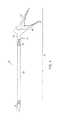
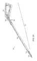
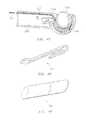
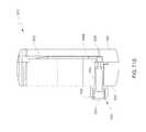
- FIG. 1is a perspective view of a suturing device of the presently disclosed embodiments.
- FIGS. 2A and 2Bare views of the suture head assembly of the suturing device of FIG. 1 .
- FIG. 2Ais a perspective assembly view of the suture head.
- FIG. 2Bis a cutaway perspective view of the suture head.
- FIGS. 3A and 3Bare segmented assembly views of the suture head assembly of FIG. 2 .
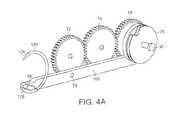
- FIGS. 4A and 4Bare cutaway segmental views of the suture head assembly showing interaction points of a suturing needle with a portion of the drive mechanism.
- FIG. 4Ashows the position of the suturing needle and drive mechanism in a “home” position prior to use or after a complete full cycle.
- FIG. 4Bshows the position of the suturing needle and drive mechanism after one full actuation of the handle, where the suturing needle is in a “rotation” position.
- FIG. 5including FIGS. 5A and 5B are expanded views of the working end of the suture head assembly with a suturing needle in the home position.
- FIG. 5Ashows the relationship between the pawl and anti-rotate spring when the suturing needle is in the home position.
- FIG. 5Bshows a close-up view of the anti-rotate spring.
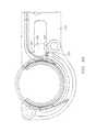
- FIGS. 6A and 6Bare expanded views of the working end of the suture head assembly during use of the device.
- FIG. 6Ashows the position of the suturing needle and the pawl immediately after the user squeezes the handle. The user then releases the handle and the pawl returns to the start position ( FIG. 6B ) while the suturing needle remains in the rotation position.
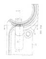
- FIG. 7including FIGS. 7A and 7B are expanded views of the pawl in contact with the C-brace while driving the suturing needle.
- FIG. 7Ashows a close-up view of the pawl spring loaded with a spring.
- FIG. 7Bshows a close-up view of the pawl, showing the heel and tip.
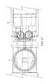
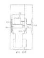
- FIGS. 8 and 9are side elevational views of a much larger scale of the internal portions of the drive mechanism located within the handle and elongated barrel.
- FIG. 8shows the drive mechanism when the handle is in an open position
- FIG. 9shows the drive mechanism when the handle is in a closed position.
- FIGS. 10-13are top and bottom views of the suture head assembly, including cables that provide the connection between the drive mechanism located in the suture head assembly and the elongated barrel when the handle is in the open and closed positions.
- FIG. 10shows a top view when the handle is in the open position.
- FIG. 11shows a bottom view when the handle is in the open position.
- FIG. 12shows a top view when the handle is in the closed position.
- FIG. 13shows a bottom view when the handle is in the closed position.
- FIG. 14is a close-up view of the cartridge holder with a tab that locks into a mating groove on the cartridge holder assembly.
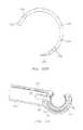
- FIG. 15is a view depicting the suturing needle positioned in the track of the cartridge.
- FIG. 16is a view showing the relation between the cartridge holder assembly, cartridge, latch and C-brace.
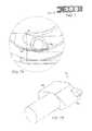
- FIGS. 17A, 17B and 17Cshow the suture head assembly.
- FIG. 17Ashows a side view of the suture head assembly.
- FIG. 17Bis a close-up side view showing the relationship between the lever and latch during attachment and ejection of the needle and cartridge from the cartridge holder assembly.
- FIG. 17Cshows a top view of the suture head assembly.
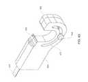
- FIG. 18is an expanded view of a curved suturing needle with notches depicted on the surface of the needle.
- FIGS. 19A and 19Bdepict two exemplary embodiments of the curved suturing needle.
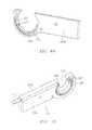
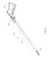
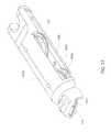
- FIGS. 20-23show different views of the suture head assembly attached to the elongated barrel via a rotation rod.
- the primary fixation point of the suture head assembly to the elongated barrelis depicted as being at the axis of lateral rotation.
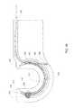
- FIG. 20shows a side view of the suture head assembly.
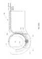
- FIG. 21shows a bottom view of the suture head assembly.
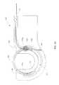
- FIG. 22shows a bottom view of the suture head assembly articulated to the left.
- FIG. 23shows a bottom view of the suture head assembly articulated to the right.
- FIGS. 24 and 25are perspective views of a suturing device.
- FIG. 24shows a perspective view of the suturing device with the handles in the open position.
- FIG. 25shows a perspective view of the suturing device with the handles in the closed position.
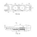
- FIG. 26is a segmented assembly view of the suture head assembly of FIGS. 24 and 25 .
- FIGS. 27A and 27Bare cutaway segmental views of the suture head assembly of FIGS. 24 and 25 showing interaction points of a suturing needle with a portion of the drive mechanism.
- FIG. 27Ashows the position of the suturing needle and drive mechanism in a “home” position prior to use or after a complete full cycle.
- FIG. 27Bshows another view of the suturing needle and drive mechanism.
- FIG. 28is a close-up view of the needle holder assembly for the suture head assembly of FIGS. 24 and 25 .
- FIG. 29is a close-up view of the distal end of the suture head assembly of FIGS. 24 and 25 .
- FIGS. 30 and 31show the suture head assembly of FIGS. 24 and 25 .
- FIG. 30shows the suture head assembly with the latch in the open position.
- FIG. 31shows the suture head assembly with the latch in the closed or locked position.
- FIG. 32is a view of a curved suturing needle with notches on the face of the suturing needle to be used with the suturing device of FIGS. 24 and 25 .
- FIG. 33shows a view of the pawl in contact with the suturing needle for the suturing device of FIGS. 24 and 25 .
- FIGS. 34 and 35show a close-up view of the suture head assembly of FIGS. 24 and 25 and the associated pulleys that move the drive mechanism.
- FIG. 34shows a top view of the suture head assembly.
- FIG. 35shows a side view of the suture head assembly.
- FIGS. 36 and 37are top views of the suture head assembly and cables that connect the drive mechanism located in the suture head assembly and the elongated barrel when the handle is in the open position for the suture device of FIGS. 24 and 25 .
- FIG. 36shows a top view of the front pulley and cable when the handle is in the open position.
- FIG. 37shows a top view of the return pulley and cable when the handle is in the open position.
- FIG. 38shows a side elevational view of the suturing device of FIGS. 24 and 25 showing parts of the drive mechanism.
- FIG. 39Ashows a top perspective view of a second embodiment of the suture head assembly made in accordance with the teachings of the invention, in which a resilient elongated member moves proximally and distally to actuate movement of the suturing needle about a circular path.
- FIG. 39Bdepicts the suturing head of FIG. 39A incorporated into a suturing device having a flexible steerable proximal segment.
- FIG. 40shows a sectional view of the drive track of the second embodiment of the suture head assembly, depicting the course of the drive tendon, the drive pawl, and the anti-rotate spring in relation to the suturing needle.
- FIG. 41is a close-up view of the distal end of the drive tendon with attached pawl.
- FIG. 42Ais an isolated view of the tendon and pawl engaging a notch in the suturing needle
- FIG. 42Bis an isolated view of an exemplary suturing needle that may be used with the second suturing head embodiment, showing a leading notch and a trailing notch on the side of the needle, and an anti-rotate notch on the outer circumference of the needle.
- FIG. 43is a sectional view of the inside structure of the drive track component of the second embodiment of the suture head assembly, without the tendon, pawl, anti-rotate spring and needle present to highlight the engagement and disengagement tracks, including a flat spring in the proximal chamber used to press the pawl against the drive notch of the needle.
- FIG. 44is a perspective view of a portion of the inside structure of the needle track component of the second embodiment of the suture head assembly, showing one of the pawl body guides, and the aperture through which the anti-rotation spring engages the outer circumference of the needle.
- FIG. 45is a top perspective view of the second embodiment of the suture head assembly, showing the placement of the thrust collar over the lateral side of the needle track, enclosing the needle within it.
- FIG. 46Ais a sectional view through the upper portion of the second embodiment of the suture head assembly, revealing the cross-section of the pawl as it engages the trailing notch of the needle, and showing the distal ends of both pawl body guides, separating the engagement track from the disengagement track. The relationship of the thrust collar to the needle and needle track is also apparent.
- FIG. 46Bis a view of the thrust collar in isolation.
- FIG. 47is a sectional view of the second embodiment of the suture head assembly showing the pawl body positioned against the flat spring, which urges the pawl tip against the side of the needle.
- the needleis partially spanning the aperture of the suture head assembly, and the anti-rotate spring is visible as it contacts the outer circumference of the needle.
- FIG. 48is an isolated view of the anti-rotate spring.
- FIG. 49is an isolated view of the flat spring, which presses against the pawl body to urge the pawl tip against the side of the needle.
- FIG. 50Ais a sectional view of the second embodiment of the suture head assembly in which the pawl is at the proximal end of the engagement drive track, immediately proximal to the trailing notch of the needle.
- FIG. 50Bis a view through section B-B of FIG. 50A showing the pawl tip pressed against the side of the needle above the notch by a compressed flat spring.
- FIG. 50Cis a top view through section C-C of FIG. 50A showing how the flat spring is deflected, pressing the pawl against the side of the needle.
- FIG. 51Ais a sectional view of the second embodiment of the suture head assembly in which the pawl is within the trailing notch of the needle at the proximal end of the engagement drive track.
- FIG. 51Bis a view through section B-B of FIG. 51A showing how the flat spring is relaxed against the pawl when the pawl tip is within the notch of the needle.
- FIG. 51Cis a top view through section C-C of FIG. 51A showing the flat spring in a non-deflected state with the pawl tip advanced within the notch of the needle, now in position to drive the needle forward.
- FIG. 52is a sectional side view of the second embodiment of the suture head assembly, showing the needle in the ‘home’ position, the anti-rotate spring engaging the needle, and the pawl within the trailing notch, in position to drive the needle through a suturing cycle.
- FIG. 53is a sectional side view of the second embodiment of the suture head assembly, showing the needle at the end of the push stroke of the first suturing cycle, the pawl having pushed the needle through the aperture, and ready to disengage from the trailing notch.
- FIG. 54is a sectional side view of the second embodiment of the suture head assembly, showing the pawl being released from the trailing notch into the distal end of the disengagement track.
- FIG. 55is a sectional side view of the second embodiment of the suture head assembly, showing the pawl being pulled by the tendon to the proximal end of the track in the pull stroke of the first suturing cycle.
- FIG. 56is a sectional side view of the second embodiment of the suture head assembly, showing the pawl approaching the proximal chamber where the proximal ends of the engagement and disengagement tracks merge. The distal end of the tendon has been deflected away from the leading notch of the needle.
- FIG. 57is a sectional side view of the second embodiment of the suture head assembly, showing the pawl being released into the leading notch of the needle by spring force from the distal tendon that had been deflected as shown in FIG. 56 .
- FIG. 58is a sectional side view of the second embodiment of the suture head assembly, showing the push stroke of the second suturing cycle, in which the pointed end of the needle is being advanced to the ‘home’ position by the pawl.
- FIG. 59is a sectional side view of the second embodiment of the suture head assembly, showing the push stroke of the second suturing cycle having been completed, the pawl being urged into the distal end of the disengagement track by the spring force of the distal tendon, and the trailing notch in proper alignment with the proximal chamber.
- FIG. 60is a sectional side view of the second embodiment of the suture head assembly, showing the pull stroke of the second suturing cycle, bringing the pawl back to the proximal end of the disengagement track to be positioned to re-initiate the suturing cycle. Backward rotation of the needle is prevented in this stroke by the anti-rotate spring engaging the anti-rotate notch of the needle.
- FIGS. 61-71Bdescribe a further embodiment of a device made in accordance with the invention.
- FIGS. 72-85describe still a further embodiment of a device made in accordance with the invention.
- the suturing device of the presently disclosed embodimentsis shown generally at 50 in FIG. 1 .
- the suturing device 50can be used to produce a continuous or interrupted stitch or suture so as to enable closure of openings internal to a patient's body.
- the suturing device 50can be utilized to suture any type of anatomical tissue in any type of anatomical cavity; and, accordingly, while the device 50 is described hereinafter for use with a cannula in endoscopic procedures, such as laparoscopy, the device 50 can be used in open surgery and with catheters and other small and large diameter tubular or hollow, cylindrical members providing access to small cavities, such as veins and arteries, as well as large cavities, such as the abdomen.
- suturing device 50includes an actuator mechanism shown generally at 52 which comprises an elongated barrel 54 and a handle 60 that extends from the undersides at a proximal end of the elongated barrel 54 .
- a suture head assembly 56is attached to the distal end of the elongated barrel 54 .
- the suture head assembly 56is removably attached to the distal end of the elongated barrel 54 .
- the length of the suture head assembly 56can range from about 20 mm to about 100 mm. In an embodiment, the length of the suture head assembly 56 is about 50 mm.
- the length of the elongated barrel 54can range from about 50 mm to about 400 mm.
- the elongated barrel 54can be made shorter or longer depending on the intended use of the device 50 .
- the elongated barrel 54is about 300 mm. In an embodiment, the elongated barrel 54 is about 350 mm.
- An articulation lever 66just distal to the top of the handle 60 is pushed or pulled to cause the suture head assembly 56 to rotate. Moving the articulation lever 66 clockwise, moves the suture head assembly 56 to the right and moving the articulation lever 66 counterclockwise, moves the suture head assembly 56 to the left. The articulation lever 66 can also be moved to articulate the suture head assembly 56 up and down.
- the suture head assembly 56is locked in place with a locking lever 64 located on an underside of the device 50 , below the articulation lever 66 .
- the suture head assembly 56may be articulated, and the elongated barrel 54 may be any length appropriate for the intended clinical application of the device 50 .
- the diameter of the device 50can range from about 3 mm to about 20 mm. In an embodiment, the diameter of the device 50 is about 12 mm. In an embodiment, the diameter of the device 50 is about 3 mm.
- a flush port 62is located on the side of the elongated barrel 54 in order to provide a port of entry for cleaning fluids or suction such that the device 50 can be cleaned prior to or after use.
- the handle 60is a grip that is squeezed in order to actuate the suturing device 50 .
- the suturing device 50is actuated by the actuator mechanism 52 coupled to a drive mechanism 70 .
- the actuator mechanism 52 of the suturing device 50may comprise a triggering mechanism that is known in the art, such as for example, the triggering mechanisms disclosed in U.S. Pat. Nos. 6,053,908 and 5,344,061, both of which are hereby incorporated by reference.
- the actuator mechanismcan be either a manually operable button or switch, or a mechanically operable by an automated electrical or a fuel driven device, such as for example, an electrical, electromagnetic or pneumatic motor powered by electrical, electromagnetic, compressed air, compressed gas, hydraulic, vacuum or hydrocarbon fuels.
- any actuator mechanism of any type known in the artcan be within the spirit and scope of the presently disclosed embodiments.
- the suturing needle(e.g., 120 , 220 ) used with the suturing device 50 has an engagement or gripping surface at one or more locations along its length.
- an engagement mechanism in the suture head assembly 56can grip the needle to advance it through the target tissue.
- This gripping surfacecan take on a number of different forms, including, for example, one or more serrations or teeth raised above or depressed below the generally toroidal surface of the suturing needle, and properly oriented to allow the suturing needle to advance smoothly through tissue.
- the engagement mechanism in the suture head assembly 56can include one or more number of interfitting teeth.
- the gripping or engagement surface of the suturing needlecan also take the form of hatch marks engraved on the surface of the suturing needle, which either may be raised above or depressed slightly below the surface of the suturing needle.
- the engagement mechanism in the suture head assembly 56can comprise a rubberized contact surface, or a collapsible mesh that can surround the body of the needle at the gripping surface to apply a trapping force against the needle.
- the gripping surfacemay include one or more notches that penetrate the surface of a suturing needle that is generally toroidal in shape, with the notches located on the outer circumference, inner circumference, or on one or both sides of the suturing needle.
- a corresponding engagement mechanism in the suture head assembly 56can comprise a pawl, which can take many forms, but which at a minimum must effectively contact the leading or forward wall of a notch on the suturing needle, either to drive the needle in a forward direction, or to prevent the needle from moving in a reverse direction.
- the following descriptionuses a particular embodiment of the gripping surface for illustrative purposes, and is not intended to limit the scope of the invention illustrated herein.
- FIG. 2Ais a perspective view of the suture head assembly 56 with a cartridge holder assembly 90 located at the distal end to which a cartridge 88 can be attached.
- the suture head assembly 56may be fabricated as a single piece.
- FIG. 2Bis a perspective assembly view of the suture head assembly of the presently disclosed embodiments showing part of the drive mechanism 70 , shown as a gear train/pulley system including pulleys 72 , 74 , 76 and 78 .
- Located within the elongated barrel 54are mechanical parts including drive shafts, belts, rods, cables, or hydraulic tubes which run from the elongated barrel 54 through the spherical portion 58 and then engages with the drive mechanism 70 in the suture head assembly 56 .
- a spherical portion 58that contains part of the drive mechanism 70 including two idler pulleys 80 and cables 84 and 86 .
- the spherical portion 58resides within the distal portion of the elongated barrel 54 and rotates in a substantially frictionless fashion.
- the drive mechanism 70includes a gear train/pulley system (“locomotive-type” drive mechanism) and cables and rods that extend from the distal end of the suture head assembly 56 to the proximal end of the elongated barrel 54 .
- the suture head assembly 56is that portion of the device 50 within which the mechanism for driving the curved needle 120 in a complete 360-degree circular arc, as well as the cartridge holder assembly 90 for attaching and releasing the cartridge 88 are situated.
- the suturing device 50is unique in the fact that the orientation of the suture head assembly 56 is such that when the cartridge 88 is attached to the suture head assembly 56 the needle 120 is driven in a curved path about an axis approximately perpendicular to the longitudinal axis of the device 50 . In this way, the needle 120 may be optimally visualized as the needle 120 is driven in a circular arc. Also, as shown in FIG. 2B , the needle 120 and cartridge 88 are in a plane parallel to the drive mechanism 70 and fit into the same space in the suture head assembly 56 .
- the improved visibility offered by the shape and configuration of the suture head assembly 56enables precise device placement over the incision or other target tissue of interest, and uniform advancement of the suturing device 50 after every stitch to provide a uniform and symmetric suture, thereby minimizing the risk of tearing tissue and bleeding due to a stitch being positioned too close to the edge of the incised tissue.
- the entire device 50 or parts of the device 50such as the suture head assembly 56 , the elongated barrel 54 , the handle 60 , and the needle 120 and cartridge 88 , may be composed of a sterilizable medical grade plastic material, in which case, the entire device 50 or parts of the device 50 may discarded and disposed after a single use.
- the device 50may be composed of a sterilizable medical grade metallic material such as stainless steel to enable reuse subsequent to sterilization following a prior use.
- the device 50is composed of a sterilizable medical grade metallic material such as titanium to enable reuse subsequent to sterilization following a prior use.
- the use of titaniumis ideal for certain procedures including Magnetic Resonance Imaging (MRI) and Computed Tomography (CT) because they are X-Ray radiolucent and do not interfere with MRI and CT scans.
- FIGS. 3A and 3Bprovide detailed segmental views of the suture head assembly 56 showing the cartridge holder assembly 90 , the disposable needle cartridge 88 , a curved suturing needle 120 , and parts of the drive mechanism 70 including a plurality of pulleys, 72 , 74 , 76 , 78 and 80 involved in driving the needle driver 98 through a semicircular path.
- the needle driveris a pawl 98 .
- a shoulder screw 108is used to keep a latch 110 locked in place over the disposable cartridge 88 and the suturing needle 120 .
- Pulleys 72 , 74 , 76 and 78are engaged with an actuator arm 102 , which is attached to the pawl 98 .
- the pawl 98interfits with two notches 132 (as depicted in FIG. 15 ) located on the needle 120 at 180 degrees apart from each other which drives the curved needle 120 in a completely circular arc.
- the suture head assembly 56is preferably configured so that the pawl 98 (or other needle driver), does not intrude into or obstruct the area within the curve of the needle 120 .
- the entire area within the circular arc of the needle 120is unobstructed; there is no hub at the center of the circular arc so that the device 50 can encompass the maximum volume of tissue within the circular arc of the curved needle 120 . In this way, the needle 120 may be rotated through a relatively large arc, allowing the needle 120 to obtain a sufficient “bite” into the tissue.
- the needle 120will have a radius of curvature of about 3 mm to about 40 mm.
- the device 50sutures within the limit of the diameter of the suture head assembly 56 , which is advantageous to suturing through small cannulas during minimally invasive surgery.
- the diameter of the curved needle 120does not exceed the diameter of the suture head assembly 56 .
- FIGS. 4A and 4Bshow detailed views of the drive mechanism 70 located in the suture head assembly 56 with respect to driving the needle 120 during use of the device 50 (the cartridge housing 88 has been removed to show the drive mechanism 70 in detail).
- the drive mechanism 70includes a plurality of pulleys, 72 , 74 , 76 and 78 , and the associated axle pins 82 , involved in driving the pawl 98 through a semicircular path.
- the actuator arm 102engages pulleys 72 and 76 and are pinned 75 to pulleys 72 and 76 .
- pulley 74acts as an idler pulley, transferring the motion to the most distal pulley 72 .
- Pulley 72 and pulley 76rotate through identical arcs.
- the actuator arm 102provides a connection to the pawl 98 .
- the pawl 98is located in the distal end of the actuator arm 102 .
- the pawl 98is attached to the actuator arm 102 by an integral shaft and collar 100 that fits loosely into the actuator arm 102 allowing smooth movement. As the handle 60 is closed and opened, the pawl 98 moves through the same arc as pulleys 72 and 76 .
- FIG. 4Ashows a detailed view of the drive mechanism 70 and the suturing needle 120 either prior to using the device 50 or after one complete full cycle of the device 50 .
- FIG. 4Bshows a detailed view of the drive mechanism 70 and the suturing needle 120 after one squeeze of the handle 60 .
- the drive mechanism 70has moved in a circular arc greater than about 180 degrees, (about 190 degrees), while the suturing needle 120 has moved in a circular arc of about 190 degrees to drive through the tissue or vessel to be sutured.
- the outer surface of the actuator arm 102is shaped to accommodate a C-brace (shown as 106 in FIG. 7 ) that causes the pawl 98 to engage the needle 120 and thereby remain in contact.
- the advancing movement of the needle 120 during operationcauses the notches 132 along the radially inner edge of the needle 120 to align with the pawl 98 in the actuator arm 102 , thereby causing the pawl 98 to engage the notches 132 due to a positive pressure exerted by the C-brace (not shown), and to “lock” into the notches 132 .
- the rotary advancing movement of the needle 120is therefore controlled to occur sequentially through about 190 degrees each time the needle is actuated.
- FIG. 5Ashows a close-up view of the distal end of the suture head assembly 56 with the cartridge 88 and the needle 120 in view as well as the relationship between the pawl 98 and the actuator arm 102 with respect to the needle 120 .
- the needle 120is enclosed within the cartridge 88 , so the sharp pointed end 124 is not exposed.
- This needle position, as loaded,is referred to as the “home” position ( FIG. 5A ).
- the needle 120In the home position, the needle 120 is fully contained within the cartridge housing 88 to eliminate needle-pricks during handling of the cartridge 88 or the loaded device. Squeezing the device handle 60 fully, two times, operates the device 50 through one full cycle. As shown in FIG.
- the first full actuation of the handle 60drives the needle 120 through an about 190 degree arc.
- the pointed end of the needle 124exits the protective enclosure of the cartridge 88 , drives through the tissue to be sutured, and re-enters the protection of the cartridge 88 of the device 50 .
- This positionafter the first squeeze of the handle 60 , is referred to as the “rotation” position.
- the handle 60is then released, and the needle 120 remains in the rotation position while the pawl 98 and the actuator arm 120 return to their start position.
- the handle 60is then squeezed again driving the needle 120 through an about 190 degree arc and returning the needle 120 to the home position.
- FIG. 5Ashows the needle 120 in the home position, the pawl 98 is engaged in the notch 132 near the suture end of needle 126 .
- An anti-rotate spring 136is engaged in the notch 134 on the outer surface of the needle 120 , not allowing the needle 120 to move backwards in the cartridge 88 of the device 50 .
- a close-up view of the anti-rotate spring 136is shown in FIG. 5B .
- the needle 120comprises at least one anti-rotate notch 134 and is engaged with at least one anti-rotate spring 136 .
- the anti-rotate spring 136slips out of the notch 134 and slides over the outer surface of the needle 120 .
- the anti-rotate spring 136snaps in behind the rear corner of the needle 120 , near the suturing material or thread 146 (see FIG. 6A ).
- the anti-rotate spring 136holds the needle 120 in place, preventing the needle 120 from moving with the pawl 98 back toward the start position.
- the pawl 98returns to the start position and engages the notch 132 in the needle 120 near the pointed end 124 (see FIG. 6B ).
- the width of the aperture 118 in the cartridge 88is comparable to and corresponds with the width of the gap in the needle 120 so that when the needle 120 is in the home position (as shown in FIG. 5A ) the needle 120 does not project materially into the aperture 118 .
- Such an alignmentcauses the needle 120 to reside entirely within the cartridge 88 , thereby preventing inadvertent contact of the sharp pointed end 124 with the user's fingers during handling of the disposable needle cartridge 88 for placement on the cartridge holder assembly 90 or disposal after use, and while operating the suturing device 50 .
- Such protection of the needle 120 in the suturing device 50prevents accidental “needle-pricks” from occurring, thereby substantially reducing the risk of infection caused by pathogenic bacteria or viruses that may contaminate the needle 120 during or after use prior to disposal.
- the needle 120may be rotated in a curved track 92 of the cartridge 88 about the longitudinal axis of the suturing device 50 to advance the pointed needle end 124 so that the needle 120 first spans the aperture 118 and then returns to the home position.
- the suturing material or thread 146is attached to the needle 120 , and therefore follows the path of the needle 120 .
- the suturing material or thread 146may then be cut and secured by an appropriate method, such as for example, by tying, or additional stitches may be placed along the entire wound or incision by repeating the aforementioned process. Every stitch, whether a single, interrupted stitch, or one of a series of continuous, running stitches may be placed in like manner.
- the suturing device 50may be used to insert either a single stitch, or to insert a suture comprising a plurality of continuous stitches as a replacement method for a more tedious and time-consuming manual suturing process.
- the terminal end of the suturing material or thread 146may contain a knot or button to prevent the suturing material or thread 146 from pulling through the sutured tissue during placement of the first stitch.
- the cartridge 88comprises the suturing needle 120 attached to the terminal end suturing material or thread 146 , and an appropriate length of suturing material or thread 146 are all packaged in a sterilizable medical packaging material.
- FIG. 7Ashows a close-up view of the pawl 98 which rides in a track formed by the C-brace 106 and the suture head assembly 56 .
- the pawl 98is spring loaded with a spring 104 .
- the spring 104is engaged to the tip of the pawl 98 b as shown in FIG. 7A .
- the spring 104engages the pawl tip 98 b into the notch 132 in the needle 120 during the driving stroke of the device 50 when the handle 60 is closed.
- the spring 104also allows the tip of the pawl 98 b to rotate out of notch 132 of the needle 120 during the return of the pawl 98 to the start position when the handle 60 is opened.
- FIG. 7Bshows a close-up view of the pawl 98 showing the pawl heel 98 a and the pawl tip 98 b.
- the userintroduces the distal end portion of suturing device 50 into a body cavity, via a cannula assembly (not shown), and then laterally articulates the suture head assembly 56 using the articulation lever 66 located just distal to the top of the handle 60 .
- the suture head assembly 56is then positioned relative to the tissue/vessel to be sutured, and the user locks the suture head assembly 56 in place using the locking lever 64 .
- the userthen, through manipulation of suturing device 50 , positions a plurality of separated tissue segments into the opening defined at the distal end portion of the suture head assembly 56 and within the aperture of the cartridge 118 .
- the usermay manipulate the device 50 while actuating the handle 60 to close an incision with a continuous suture whose stitches may be individually tensioned precisely and uniformly along the length of the suture similar to suturing done by hand in the conventional way.
- the usermay employ a single suture which would extend the entire length of the incision or multiple sutures.
- the device 50starts with the needle 120 in the home position and the handle 60 fully open (see FIG. 8 ).
- the handle 60is made up of a grip which rests in the user's palm and is squeezed in order to actuate the device 50 .
- the usersqueezes the handle 60 moving the needle 120 from the home position to the rotation position.
- the handle 60contains linkages 144 to both the upper drive rod 142 and the lower drive rod 140 . Squeezing the handle 60 (see FIG. 9 ) causes the two drive rods 140 and 142 to move in opposite directions.
- the upper drive rod 142moves forward while the lower drive rod 140 moves backward.
- the drive rodsare connected to the suture head assembly 56 with cables 84 and 86 and idler pulleys 80 .
- the upper rod 142is connected to pulley 78 with cable 84 .
- the lower rod 140is connected to pulley 76 with cable 86 .
- FIGS. 10 and 11 in conjunction with FIG. 8show the connections and positions of cables 84 and 86 and the drive pulleys 72 , 74 , 76 and 78 when the handle 60 is in the open position.
- FIGS. 12 and 13 in conjunction with FIG. 9show the connections and positions of cables 84 and 86 and the drive pulleys 72 , 74 , 76 and 78 when the handle 60 is in the closed position.
- the force to move needle 120 from the home position to the rotation positioncomes from the lower rod 140 pulling backward on the drive cable 86 .
- the lower rod 140extends nearly the full length of the elongated barrel 54 , connecting to drive cable 86 , at the proximal end of the elongated barrel 54 . As shown in FIG.
- cable 86exits the elongated barrel 54 and enters the suture head assembly 56 , passing over an idler pulley 80 located in the spherical portion 58 , then wrapping clockwise (as viewed from the bottom) around pulley 76 and is secured to pulley 76 located in the suture head assembly 56 .
- the pulling action of cable 86causes pulley 76 to rotate through an arc of approximately 190 degrees.
- the upper rod 142moves forward.
- the upper rod 142also extends nearly the full length of the elongated barrel 54 , connecting to drive cable 84 , at the proximal end of the elongated barrel 54 . As shown in FIG.
- cable 84also exits the elongated barrel 54 and enters suture head assembly 56 , passing over a second idler pulley 80 located in the spherical portion 58 , then wrapping (clockwise as viewed from the top) around pulley 78 and is secured to pulley 78 located in the suture head assembly 56 .
- Pulley 78is directly linked to pulley 76 through the actuator arm 102 , and cables 84 and 86 are wrapped in opposing directions, so that as cable 86 unwinds from pulley 76 , cable 84 winds onto pulley 78 .
- the needle 120is held in a path of rotation by a combination of three components.
- the cartridge 88 , the C-brace 106 and the cartridge holder assembly 90interact to constrain the needle 120 to the path of rotation (see FIG. 5 ).
- the cartridge 88is a semicircular shaped component that is held into the device 50 by a plurality of extensions 94 located on each end of the cartridge 88 (see FIGS. 14 and 15 ).
- the plurality of extensions 94takes the form of tabs.
- the cartridge 88is made from a sterilizable medical grade metallic material such as stainless steel.
- the cartridge 88provides some of the support structure for keeping the needle 120 in a rotational path and therefore should be constructed from a material with structural integrity.
- the plurality of extensionsare tabs extending from the cartridge housing 88 .
- the plurality of extensions 94lock into mating grooves 96 located along on the distal edge of the cartridge holder assembly 90 that are located diametrically opposite to one another, and are capable of engaging the plurality of extensions 94 correspondingly located in the needle cartridge housing 88 as shown in FIG. 16 .
- the proximal end of cartridge 88is held in place by a cartridge holder assembly 90 , as shown in FIG. 17A .
- the cartridge holder assembly 90also includes a latch 110 , a lever 112 , associated pins 114 and 116 , a shoulder screw 108 , an anti-rotate spring 136 and at least one groove 96 that can engage with the plurality of extensions 94 located on the cartridge 88 . It is the interaction of all of the elements of the cartridge holder assembly 90 that hold and lock the cartridge 88 in place.
- the latch 110slides back to release the cartridge 88 and forward to lock the cartridge 88 in place.
- the latch 110also has a built into ejector feature, as shown in FIG. 17B .
- a lever 112is located distal and below the needle 120 and the cartridge 88 .
- the lever 112pivots on a pin 114 .
- a second pin 116located above the pivot pin 114 , engages with a slot in the latch 110 .
- the latch 110is pulled back and the lever 112 is rotated up and back, causing pin 116 to move back with the latch 110 and to rotate about pin 114 thus pushing the needle 120 and the cartridge 88 from the cartridge holder assembly 90 .
- the needle 120 and the cartridge 88are then removed from the device 50 by a slight proximal motion to disengage the plurality of extensions 94 from their mating grooves 96 in the cartridge holder assembly 90 .
- 17Cshows the needle 120 as it is driven through a first semi circular arc (the handle 60 has partially completed a first full squeeze).
- the anti-rotate spring 136slips out of the notch 134 and slides over the outer surface of the needle 120 .
- Loading of the needle 120 and the cartridge 88is accomplished by engaging the plurality of extensions 94 into both grooves 96 on the cartridge holder assembly 90 and then pressing the proximal ends down against the sloped distal surface of the latch 110 .
- the latch 110is spring loaded at the proximal end, thus can slide back as the needle 120 and the cartridge 88 are pressed into place and then snap closed to the locked position, retaining the needle 120 and the cartridge 88 .
- the lever 112is down and out of the way of the operation of the needle 120 and the cartridge 88 .
- FIG. 18shows a close-up view of the needle 120 .
- the two notches 132are located about 180 degrees apart on the inner surface and assist in driving the needle 120 .
- the pawl 98engages the notches 132 when driving the needle 120 through the circular motion.
- a third notch 134is located on the outer surface of the needle 120 .
- the notch 134assists in preventing rotation of the needle 120 and provides an anti-rotation feature.
- the needle 120is formed as a circular split ring with a gap 122 , a sharp, pointed end 124 , and a blunt end 126 .
- the needle 120further comprises an opening 130 to accommodate the leading end of the suturing material or thread 146 .
- the opening 130is the form of an eye though which the leading end of the suturing material or thread 146 may be passed through for attachment to the needle 120 .
- the opening 130is located adjacent to the blunt end 126 .
- the opening 130can be positioned anywhere along the arc or the needle 120 between the apex 128 and the blunt end 126 .
- the needle 120comprises an opening 130 in the form of a cylindrical bore aligned axially with respect to the needle 120 , located at the blunt end 126 ( FIG. 19B ). The leading end of the suturing material or thread 146 is inserted into the opening 130 and restrained by mechanically crimping.
- the arc length of the needle 120is preferably about 240 degrees to about 300 degrees.
- the needle 120comprises two symmetric notches 132 along the radially inner edge (“inner notches”) that are positioned proximally to the sharp, pointed end 124 and the blunt end 126 of the needle 120 .
- the notches 132are located directly opposite to each other, each having a perpendicular (about 90 degree) segment and an angular segment that makes an angle of about 60 degrees with the perpendicular segment.
- the inner notches 132are engaged by the needle driver 98 of the drive mechanism 70 and enable the needle 120 to undergo a rotary movement upon actuation of the drive mechanism 70 , thereby causing the needle 120 to penetrate into and advance through tissue.
- a similar triangular notch 134is located on the radially outer edge (“outer notch”) of the needle 120 proximally to the inner notch 132 closer to the sharp, pointed end 124 .
- the outer notch 134engages with the anti-rotate spring 136 located on the cartridge holder assembly 90 , whereby rotation of the needle 120 in a direction opposite to the advancing direction or “needle backing-up” is prevented.
- the positive engagement of the needle outer notch 134 during operation of the suturing deviceprecludes needle 120 from straying out of sequence during the suturing process.
- the suture head assembly 56 of the device 50can be laterally articulated to the left of center and also to the right of center. In one embodiment, the suture head assembly 56 can be laterally articulated through an arc of about 22.5 degrees to the left of center and also to the right of center, for a total of about 45 degrees or more. In addition, the suture head assembly can be articulated up and down. In one embodiment, the suture head assembly 56 can be articulated up and down. The ability of the suture head assembly 56 to be articulated to the left and right of center, as well as up and down, permits the user to position the suture head assembly 56 for many different types of suturing applications.
- the articulation lever 66just distal of the top of the handle 60 , is pushed or pulled to cause the suture head assembly 56 to rotate. Viewed from above, moving the articulation lever 66 clockwise moves suture head assembly 56 to the right and moving the articulation lever 66 counterclockwise moves suture head assembly 56 to the left. The suture head assembly 56 is locked in place with the locking lever 64 located on the bottom of the device 50 , below the articulation lever 66 . Movement is accomplished using the solid articulation rod 68 to link the articulation lever 66 to the suture head assembly 56 .
- the articulation rod 68is pinned to the articulation lever 66 and to one side of the most proximal section of the suture head assembly 56 so that the articulation rod 68 pushes or pulls the suture head assembly 56 through a full range of motion (see FIGS. 20-23 ).
- FIGS. 20-23show the articulation rod 68 in the elongated barrel 54 and the connection to the suture head assembly 56 .
- the suture head assembly 56is shown moving from left articulation, to straight to right articulation (some components are not shown to allow clear viewing of the linkage).
- FIG. 20shows a side view of the suture head assembly 56 .
- FIG. 21shows a bottom view of the suture head assembly 56 with no articulation.
- FIG. 22shows a bottom view of the suture head assembly 56 articulated to the left.
- FIG. 23shows a bottom view of the suture head assembly 56 articulated to the right.
- FIGS. 20-23show a number of items.
- the articulation rod 68runs down the center of the elongated barrel 54 and is attached to one side of the spherical portion 58 .
- the function of the articulation rod 68is to push and pull the suture head assembly 56 through an articulation.
- the two idler pulleys 80which drive cables 84 and 86 are located in the spherical portion 58 . Looking at FIG. 20 , the two idler pulleys 80 seem to be one on top of the other. Instead however, they are located in plane with either pulley 76 and lower rod 140 or pulley 78 and upper rod 142 .
- the entire suturing device 50can be designed as a single unit which may be either reusable or disposed after a single use. If desired, the entire suturing device 50 can be designed from a number of units which, each unit may be either reusable or disposed after a single use.
- the suturing device 50is preferably configured to provide a “pistol like” grip for the user that includes an elongated barrel 54 and a handle 60 that extends from the proximal end of the elongated barrel 54 .
- the elongated barrel 54has either a linear or non-linear configuration, including but not limited to, straight, curved and angled configurations.
- a suture head assembly 56is removably attached to the distal end of the elongated barrel 54 .
- the suture head assembly 56contains a portion of the drive mechanism 70 of the device 50 .
- the working end of the suture head assembly 56has a cartridge holder assembly 90 to which a disposable cartridge 88 that is capable of accommodating a suturing needle 120 may reside.
- the disposable cartridge 88preferably has a generally cylindrical housing with an opening or aperture 118 in the sidewall of the housing at the distal or working end thereof.
- An arcuate suturing needle 120having a sharp, pointed end 124 is slidably mounted in a circular track 92 of the cartridge 88 .
- a blunt end of the needle 126is connected to a suturing material or thread 146 .
- the radius of the arc defining the arcuate suturing needle 120is approximately equal to the circumference to the cartridge housing 88 at the aperture 118 therein.
- the needle 120normally resides in a “home” position in the track 92 such that the gap in the arcuate suturing needle 122 is in alignment with the aperture 118 in the cartridge 88 .
- the sharp, pointed end of the needle 124is situated on one side and entirely within the confines of the housing aperture 118 ; the pointed end of the needle 124 is, therefore, shielded by the cartridge housing 88 .
- the blunt end of the suturing needle 126 that is attached to the suturing material or thread 146is located at the opposite side of the aperture 118 .
- the sharp, pointed end of the needle 124is, therefore, wholly contained within the cartridge 88 and does not protrude beyond the housing of the cartridge 88 . Thus, the sharp pointed end of the needle 124 is not exposed to the user.
- the needle 120may be releasably engaged by a needle driver 98 that is rotatably mounted within the suture head assembly 56 so that the needle 120 can be rotated from the home position by about 360 degrees about the central vertical axis of the cartridge 88 .
- a rotary action of the needle 120causes the sharp point 124 to advance across the cartridge housing 88 so as to span the aperture 118 .
- the needle 120penetrates the tissue segments and spans the incision between them.
- a continued rotary movement of the needle 120causes the needle 120 to return to the home position, and thereby causes the suturing material or thread 146 attached to the needle 120 to be pulled into and through the tissue in an inward direction on one side of the tissue incision, and upwards and out through the tissue on the opposite side of the incision.
- the suture material or thread 146follows the curved path of the needle 120 to bind the tissues together with a stitch of material or thread 146 across the incision in a manner similar to manual suturing, wherein the needle 120 is “pushed” from the blunt end 126 and then “pulled” from the pointed end 124 by the pawl 98 .
- an anchoring mechanismis provided at the trailing terminal end of the suturing material or thread 146 to prevent the material 146 from being pulled completely through and out of the tissue segments.
- the anchoring mechanismcan be a pre-tied or a welded loop, a knot wherein the suture material or thread 146 is simply tied, or a double-stranded, looped suture is that attached to the suturing needle 120 .
- the rotary movement of the needle 120 within the needle cartridge 88is accomplished by a pawl 98 that may be operated by the user by holding the suturing device 50 with one hand in a pistol-like grip around the handle 60 , and using at least one finger of that hand to activate.
- the suturing device 50 of the presently disclosed embodimentscan be used for a laparoscopic procedure, including but not limited to laparoscopic colostomy, colectomy, adrenalectomy, splenectomy, repair of paraesophageal hernia, inguinal hernia repair, ventral hernia repair, Nissen fundoplication, liver lobectomy, gastrectomy, small bowel resection, treatment of small bowel obstruction, distal pancreatectomy, nephrectomy and gastric bypass.
- laparoscopic procedureincluding but not limited to laparoscopic colostomy, colectomy, adrenalectomy, splenectomy, repair of paraesophageal hernia, inguinal hernia repair, ventral hernia repair, Nissen fundoplication, liver lobectomy, gastrectomy, small bowel resection, treatment of small bowel obstruction, distal pancreatectomy, nephrectomy and gastric bypass.
- laparoscopic colostomyincluding but not limited
- the abdomenis insufflated with gas to create a working space for the user.
- gasAny gas known to those skilled in the art including, but not limited to, nitrogen or carbon dioxide, can be used.
- Access portalsare established using trocars in locations to suit the particular surgical procedure. A variety of surgical instruments may then be inserted into the body through these access ports/cannulas. The user then introduces the distal end portion of suturing device 50 into a cannula, and then laterally articulates the suture head assembly 56 using the articulation lever 66 located just distal to the top of the handle 60 .
- the suture head assembly 56is then positioned relative to the tissue/vessel to be sutured together, and the user locks the suture head assembly 56 in place using the locking lever 64 .
- the userthen, through manipulation of suturing device 50 , positions a plurality of separated tissue segments into the opening defined at the distal end portion of the suture head assembly 56 and within the aperture 118 of the cartridge 88 .
- the userusing only one hand, may manipulate the device 50 while actuating the handle 60 to close an incision with a continuous suture whose stitches may be individually tensioned precisely and uniformly along the length of the suture similar to suturing done by hand in the conventional way.
- the usermay employ a single suture which would extend the entire length of the incision or multiple sutures.
- the suturing device 50enables the user to lay down a running stitch or interrupted stitch to close the tissue incision in a time efficient manner.
- any conventional procedure for conducting laparoscopic surgerycan be used with the device 50 .
- the needle cartridge 88is disposably mounted on a cartridge holder assembly 90 at the distal end of the suture head assembly 56 .
- the minimalized structural design of the suture head assembly 56enables the user to have a clear, unobstructed view of the suturing needle 120 during advancement through the tissue segments during the course of a suturing operation, thereby enabling precise placement of the suturing device 50 to provide uniform sutures and precluding the risk of tearing tissue by placement too close to the edge of the incision.
- the suturing device 50is then advanced a short distance along the incision and the aforementioned operation is repeated to produce another stitch comprising the suturing material or thread 146 .
- the usermay continue to manipulate the suturing device 50 , alternately advancing and actuating rotation of the needle 120 about an axis that is generally parallel to the direction of advancement to create a continuous suture which may extend through the entire length of the incision or a series of interrupted stitches.
- the stitchis tightened by exerting a pull on the suturing material or thread 146 so that the resultant suture is tensioned uniformly along the length of the incised tissue segments. Therefore, a tight closure of the segments is accomplished and bleeding and tearing of tissue are minimized.
- the usercan use a needle grasper to tighten and knot the formed stitches.
- the presently disclosed embodimentsprovide a method for suturing tissue during minimally invasive surgery including engaging a cartridge 88 to a suture head assembly 56 at a distal end of a suturing device 50 , the cartridge 88 having a protective housing and a suturing needle 120 with a pointed end 124 and a blunt end 126 ; introducing the distal end of the suturing device 50 into a body cavity; positioning an opening 118 in the cartridge 88 to span a plurality of separated tissue segments; activating an actuator 52 coupled to a drive mechanism 70 that engages the suturing needle 120 to cause rotational movement of the suturing needle 120 about an axis approximately perpendicular to a longitudinal axis of the suturing device 50 and advance the suturing needle 120 through the plurality of separated tissue segments; and pulling a suturing material 146 attached to the suturing needle 120 through the plurality of separated tissue segments forming a stitch.
- the presently disclosed embodimentsprovide a method for suturing tissue during minimally invasive surgery including (a) engaging a cartridge 88 to a suture head assembly 56 at a distal end of a suturing device 50 , the cartridge 88 having a protective housing and a suturing needle 120 with a pointed end 124 and a blunt end 126 ; (b) introducing the distal end of the suturing device 50 into a body cavity; (c) positioning an opening 118 in the cartridge 88 to span a plurality of separated tissue segments; (d) activating an actuator 52 coupled to a drive mechanism 70 that engages the suturing needle 120 to cause rotational movement of the suturing needle 120 about an axis approximately perpendicular to a longitudinal axis of the suturing device 50 and advance the suturing needle 120 through the plurality of separated tissue segments; (e) pulling a suturing material 146 attached to the suturing needle 120 through the plurality of separated tissue segments forming a stitch and repeating steps (c) through (e
- the presently disclosed embodimentsprovide a method for suturing tissue during minimally invasive surgery including inserting a distal end of a suturing device 50 having a suturing needle 120 with a pointed end 124 into a body; positioning the suturing needle 120 to span a plurality of separated tissue segments; activating an actuator 52 a first time causing the pointed end 124 of the suturing needle 120 to extend beyond a protective housing of a cartridge 88 to engage the plurality of separated tissue segments; activating the actuator 52 a second time to cause the suturing needle 120 to complete a revolution and pull a suture 146 extending from the suturing needle 120 through the plurality of separated tissue segments to form a stitch.
- the suturing device 50may be configured in different ways with respect to length and angle of the suture head assembly 56 .
- the size of the needle 120 , the needle cartridge 88 , the cartridge aperture 118 and the aperture positionmay also be varied for use in open surgery to perform procedures such as closing of the fascia, skin closure, soft tissue attachment, anastomosis, fixation of mesh, grafts and other artificial materials.
- FIGS. 24 and 25show an alternative embodiment of a suturing device shown generally at 150 .
- the suturing device 150can be used to produce a continuous or interrupted stitch or suture so as to enable closure of openings internal to a patient's body.
- the suturing device 150can be utilized to suture any type of anatomical tissue in any type of anatomical cavity; and, accordingly, while the device 150 is described hereinafter for use with a cannula in endoscopic procedures, such as laparoscopy, the device 150 can be used in open surgery and with catheters and other small and large diameter tubular or hollow, cylindrical members providing access to small cavities, such as veins and arteries, as well as large cavities, such as the abdomen.
- the suturing device 150includes an actuator mechanism shown generally at 152 which comprises an elongated barrel 154 and a handle 160 that extends from the undersides at a proximal end of the elongated barrel 154 .
- Located within the elongated barrel 154are mechanical parts including cables which run from the elongated barrel 154 through a spherical portion 158 and then engages with the drive mechanism in a suture head assembly 156 .
- the spherical portion 158resides within the distal portion of the elongated barrel 154 and rotates with low friction.
- a drive mechanism 170includes a pulley system and cables that extend from the distal end of the suture head assembly 156 to the proximal end of the elongated barrel 154 .
- the suture head assembly 156houses the mechanism for driving a curved needle 220 in a complete 360 degree circular arc.
- the orientation of the suture head assembly 156is such that when the needle 220 is attached to the suture head assembly 156 the needle 220 is driven in a curved path about an axis approximately perpendicular to the longitudinal axis of the device 150 . In this way, the needle 220 may be optimally visualized as the needle 220 is driven in a circular arc. Also, as shown in FIGS. 24 and 25 , the needle 220 is in a plane parallel to the drive mechanism and fits into the same space in the suture head assembly 156 .
- the improved visibility offered by the shape and configuration of the suture head assembly 156enables precise device placement over the incision, and uniform advancement of the suturing device 150 after every stitch to provide a uniform and symmetric suture, thereby minimizing the risk of tearing tissue and bleeding due to a stitch being positioned too close to the edge of the incised tissue.
- the entire device 150 or parts of the device 150such as the suture head assembly 156 , the elongated barrel 154 , the handle 160 , and the needle 220 , are composed of a sterilizable medical grade plastic material, in which case, the entire device 150 or parts of the device 150 may discarded and disposed after a single use.
- the device 150is composed of a sterilizable medical grade metallic material such as stainless steel to enable reuse subsequent to sterilization following a prior use.
- the device 150is composed of a sterilizable medical grade metallic material such as titanium to enable reuse subsequent to sterilization following a prior use.
- the use of titaniumis beneficial for certain procedures including Magnetic Resonance Imaging (MRI) and Computed Tomography (CT) because they are X-Ray radiolucent and do not interfere with MRI and CT scans.
- FIG. 24shows the handle 160 in an open position.
- FIG. 25shows the handle 160 in the closed position.
- the suture head assembly 156is attached to the distal end of the elongated barrel 154 .
- the suture head assembly 156is removably attached to the distal end of the elongated barrel 154 .
- the length of the suture head assembly 156can range from about 10 mm to about 100 mm. In a particular embodiment, the length of the suture head assembly 156 is about 40 mm.
- the length of the elongated barrel 154can range from about 50 mm to about 400 mm. Those skilled in the art will recognize that the elongated barrel 154 can be made shorter or longer depending on the intended use of the device 150 .
- the elongated barrel 154is about 300 mm in length. In another embodiment, the elongated barrel 154 is about 350 mm in length.
- An articulation lever 166just distal to the top of the handle 160 is pushed or pulled to cause the suture head assembly 156 to rotate. Moving the articulation lever 166 clockwise moves the suture head assembly 156 to the right and moving the articulation lever 166 counterclockwise moves the suture head assembly 156 to the left. The articulation lever 166 can also be moved to articulate the suture head assembly 156 up and down, as desired. The suture head assembly 156 is locked in place with a locking lever 164 located on an underside of the device 150 , below the articulation lever 166 .
- the suture head assembly 156may be articulated, and the elongated barrel 154 may be any length appropriate for the intended clinical application of the device 150 .
- the diameter of the device 150can range from about 3 mm to about 20 mm. In one embodiment, the diameter of the device 150 is about 12 mm. In another embodiment, the diameter of the device 150 is about 3 mm.
- the handle 160may be a grip that is squeezed in order to actuate the suturing device 150 .
- the suturing device 150is actuated by the actuator mechanism 152 coupled to a drive mechanism 170 .
- the actuator mechanism 152 of the suturing device 150may comprise a triggering mechanism that is known in the art, such as for example, the triggering mechanisms disclosed in U.S. Pat. No. 6,053,908 and U.S. Pat. No. 5,344,061, both of which are hereby incorporated by reference.
- the actuator mechanism 152can be either a manually operable button or switch, or mechanically operable by an automated electrical or a fuel driven device, such as for example, an electrical, electromagnetic or pneumatic motor powered by electrical, electromagnetic, compressed air, compressed gas, hydraulic, vacuum or hydrocarbon fuels.
- an electrical, electromagnetic or pneumatic motor powered by electrical, electromagnetic, compressed air, compressed gas, hydraulic, vacuum or hydrocarbon fuelssuch as for example, an electrical, electromagnetic or pneumatic motor powered by electrical, electromagnetic, compressed air, compressed gas, hydraulic, vacuum or hydrocarbon fuels.
- FIG. 26provides an assembly view of the suture head assembly 156 .
- the suture head assembly 156is fabricated from multiple pieces including a holder assembly 190 , a needle holder assembly 188 , a latch 210 , and parts of the drive mechanism 170 including a plurality of pulleys, 172 , 174 and 176 and two idler pulleys 180 involved in driving a needle driver 198 through a semicircular path.
- Pulleys 172 and 174may include a set of four pulleys, or two sets of pulleys, labeled 178 .
- the needle driveris a pawl 198 .
- a shoulder screw 208 and a plurality of needle assembly extensions 194may be used to keep the latch 210 locked in place over the needle holder assembly 188 and the suturing needle 220 .
- the needle holder assembly 188includes a curved track 192 where the needle 220 rides. Pulleys 172 , 174 and 176 are engaged with an actuator arm 202 , which is attached to the pawl 198 .
- the pawl 198interfits with two notches 232 located on the face of the needle 220 at about 180 degrees apart which drives the curved needle 220 in a circular arc.
- the suture head assembly 156is configured so that the pawl 198 or other needle driver known in the art, does not intrude into or obstruct the area within the curve of the needle 220 .
- the area within the circular arc of the needle 220is unobstructed; there is not a hub at the center of the circular arc so that the device 150 can encompass the maximum volume of tissue within the circular arc of the curved needle 220 .
- the needle 220may be rotated through a relatively large arc, allowing the needle 220 to obtain a sufficient “bite” into the tissue.
- the needle 220will have a radius of curvature of about 3 mm to about 40 mm.
- the device 150sutures within the limit of the diameter of the suture head assembly 156 , which is advantageous to suturing through small cannulas during minimally invasive surgery.
- the diameter of the curved needle 220does not exceed the diameter of the suture head assembly 156 .
- FIGS. 27A and 27Bshow detailed views of the drive mechanism 170 located in the suture head assembly 156 with respect to driving the needle 220 during use of the device 150 (the needle holder assembly 188 and the holder assembly 190 have been removed to show the drive mechanism 170 in detail).
- the drive mechanism 170includes the actuator arm 202 that engages pulleys 172 , 174 , and 176 and the pawl 198 that drives the needle 220 through a curved path.
- the pawl 198is located in the distal end of the actuator arm 202 and is capable of engaging the notches 232 located along the face of the needle 220 .
- a flat spring 200keeps the pawl 198 engaged into the notches 232 of the needle 220 .
- the pawl 198When the needle 220 is pushed around, the pawl 198 will be pushed back up against the flat spring 200 and allow the needle 220 to cycle. As the handle 160 is closed and opened, the pawl 198 moves through the same arc as the pulleys.
- the actuator arm 202is activated by the user upon squeezing of the handle 160 , and is capable of sweeping back and forth in an arc spanning about 190 degrees or more.
- FIG. 28shows a close-up view of the needle holder assembly 188 showing the curved track 192 where the needle 220 resides as well as the needle holder assembly extensions 194 that help keep the latch 210 in place.
- the suturing needle 220follows a curved path along the track 192 during rotation of the suturing needle 220 .
- the curved track 192 for the needle 220may be machined into the needle assembly 188 and provides a captive curved track 192 so that the needle 220 can be driven around with precision.
- the curved track 192includes an inside slot and a larger slot surrounding the inside slot.
- the larger outside slotprovides clearance for the pawl 198 , so that the pawl 198 can maneuver around without hitting anything
- the smaller inside slotprovides clearance for a pawl tip 199 , which goes through the smaller inside slot and then into the needle 220 so that the pawl tip 199 can drive the needle 220 .
- FIG. 29shows a close-up view of the suture head assembly 156 with the needle holder assembly 188 , the holder assembly 190 , the latch 210 and the needle 220 in view as well as the relationship between the pawl 198 and the actuator arm 202 with respect to the needle 220 .
- the needle 220is enclosed within the needle holder assembly 188 , so the sharp pointed end 224 of the needle 220 is not exposed.
- This needle 220 position, as loaded,is referred to as the “home” position. In the home position, the needle 220 is fully contained within the needle holder assembly 188 to eliminate needle-pricks during handling of the suture head assembly 156 .
- the needle assembly extensions 194form a “tongue-in-groove” connection with the latch 210 , which keeps the forces from the needle 220 from opening the thin members of the latch 210 .
- the needle assembly extensions 194cause an entrapment at a distal end of the suturing device, thus locking the latch 210 in place.
- Squeezing the device handle 160fully operates the device 150 through one full cycle.
- the first full actuation of the handle 160drives the needle 220 through about a 190-degree arc.
- the pointed end 224 of the needle 220exits the protective enclosure of the needle holder assembly 188 , drives through the tissue to be sutured, and re-enters the protection of the needle holder assembly 188 of the device 150 .
- This positionafter the first squeeze of the handle 160 , is referred to as the “rotation” position.
- the handle 160is then released, and the needle 220 remains in the rotation position while the pawl 198 and the actuator arm 220 return to their start position.
- the handle 160is then squeezed again driving the needle 220 through about a 190-degree arc returning the needle 220 to the home position.
- a flat pawl spring 200keeps the pawl 198 engaged into the pawl notches 232 on the needle 220 .
- the needle 220is pushed around the pawl 198 will be pushed back up against the flat pawl spring 200 and allow the needle 220 to cycle.
- FIGS. 30 and 31show top views of the suture head assembly 156 .
- Needle holder assembly 188forms a connection with the latch 210 .
- the latch 210forms a top cover over the suturing needle 220 which is in the curved track 192 of the needle holder assembly 188 .
- FIG. 30shows the latch 210 in the open position, which is for needle 220 removal and insertion into the needle holder assembly 188 .
- To insert and/or remove the needle 220a user may turn the needle 220 180 degrees in its curved track 192 from the as-drawn position.
- a usermay grab the needle 220 by hand or with a surgical tool to either install the needle 220 or remove the needle 220 . By grabbing and lifting the needle 220 out, the needle 220 is removed. By grabbing the needle 220 the needle can be inserted when the latch 210 in the open position.
- FIG. 31shows the latch 210 in the locked position, also known as the forward position.
- FIG. 32shows the suturing needle 220 .
- the two notches 232are located about 180 degrees apart on the face of the needle 220 and assist in driving the needle 220 .
- the pawl 198engages the notches 232 when driving the needle 220 through the circular motion.
- a third notch 234is located on the outer surface of the needle 220 .
- the notch 234provides an anti-rotation feature by preventing rotation of the needle 220 .
- the needle 220is formed as a circular split ring with a gap 222 , a sharp, pointed end 224 , and a blunt end 226 .
- the needle 220further comprises an opening 230 to accommodate the leading end of the suturing material or thread 246 .
- the opening 230is the form of an eye though which the leading end of the suturing material or thread 246 may be passed through for attachment to the needle 220 .
- the needle 220comprises an opening 230 in the form of a cylindrical bore aligned axially with respect to the needle 220 , located at the blunt end 226 .
- the opening 230can be positioned anywhere along the arc or the needle 220 between the apex 228 and the blunt end 226 .
- the leading end of the suturing material or thread 246is inserted into the opening 230 and restrained by mechanically crimping or other connection methods known in the art.
- the arc length of the needle 220is preferably about 240 degrees to about 300 degrees.
- the needle 220comprises two symmetric notches 232 along the face (“drive notches”). The notches 232 are located directly opposite to each other.
- a similar notch 234is located on the radially outer edge (“outer notch”) of the needle 220 proximally to the inner notch 232 closer to the sharp, pointed end 224 .
- the outer notch 234engages with an anti-rotate spring, whereby rotation of the needle 220 in a direction opposite to the advancing direction or “needle backing-up” is prevented.
- the positive engagement of the needle outer notch 234 during operation of the suturing deviceprecludes the needle 220 from straying out of sequence during the suturing process.
- FIG. 33shows a close-up view of the pawl tip 199 engaging the drive notches 232 of the needle 220 .
- the drive notches 232are engaged by the pawl tip 199 of the drive mechanism 170 and enable the needle 220 to undergo a rotary movement upon actuation of the drive mechanism 170 , thereby causing the needle 220 to penetrate into and advance through tissue.
- FIGS. 34 and 35show parts of the drive mechanism 170 including return pulleys 172 and 174 .
- Pulleys 172 and 174are connected to each other using wires 175 .
- pulleys 172 and 174are made up of four pulleys 178 that are connected together by laser welding or other methods known in the art.
- the four pulleys 178produce an over-rotation, of about 190 degrees.
- the over-rotationleads to the wire 175 design where there is a wire 175 on each set of pulleys 178 .
- FIG. 35shows a side view of the suture head assembly 156 which shows the two wires 175 connecting the four pulleys 178 together for synchronized rotation.
- FIGS. 36 and 37 in conjunction with FIG. 38show the connections and positions of cables 184 and 186 to the drive pulley 176 and to the return pulleys 172 and 174 , respectively, and to the when the handle 160 is in the open position.
- the cables 184 and 186may be made from stainless steel.
- FIG. 36shows a top view of the suture head assembly 156 with the cable 184 running through two idler pulleys 180 and wrapped around drive pulley 176 .
- FIG. 37shows a top view of the suture head assembly 156 with the cable 186 running through two idler pulleys 180 and wrapped around return pulley 174 .
- the cable 186runs from return pulley 174 through the elongated barrel 154 and to the very proximal end of the handle 160 .
- the force to move the needle 220 from the home position (shown in FIGS. 36 and 37 ) to a rotation positioncomes from a return spring 240 that is connected to the cable 184 , resulting in a pre-load (shown in FIG. 38 ).
- the trigger of the handle 160is squeezed closed, the handle 160 moves to the closed position and the drive pulley 176 turns counterclockwise, driving the needle 220 .
- the cable 186drives the return pulley 174 counterclockwise and cycles the actuator arm 202 to drive the needle 220 forward through the tissue.
- the needle 220is driven through a circular motion, through a cycle, and the cable 184 is compressing the return spring 240 on the other end.
- the actuator arm 202drives the needle.
- the front pulley 178which is now fully charged with the return spring 240 , will return the needle 220 to the home position.
- the return spring 240pulls cable 184 , returning the pulleys to their starting positions, and returning the actuator arm 202 to a position to engage the second drive notch of needle 220 .
- a second compression-release cyclereturns the needle 220 to the home position. Relaxing the trigger of handle 160 takes no power.
- FIG. 38shows a side elevational view of the suturing device 150 .
- the handle 160includes a number of internal parts—a cable connector 182 has a hole and a shoulder. The shoulder rides against the end of the return spring 240 , and the hole provides an opening for the cable 184 .
- the return spring 240is compressed and the cable 184 is soldered or locked to the connector 182 , so that the cable 184 provides a preload onto the return spring 240 .
- the cable 184runs from the connector 182 through the return spring 240 over pulley 244 , through the elongated barrel 154 , through the spherical portion 158 , between the idler pulleys 180 and fixed to the drive pulley 176 .
- the cable 186is connected at the very proximal end of the handle 160 and lies under pulley 245 , over pulley 242 , through the elongated barrel 154 , through the spherical portion 158 , between the idler pulleys 180 and fixed to the return pulley 174 .
- the handle 160When the handle 160 is translated from the open position to the closed position the needle 220 is driven through the tissue. A user has a tactile feel as the needle 220 moves. If the needle 220 runs across something that is impenetrable, the handle 160 will stop moving and the user could feel this in their hand holding the handle.
- the return spring 240takes on a charge, the return spring 240 has shortened in length.
- the return spring 240pulls the cable 184 and brings the needle 220 back to the home position and also brings the handle 160 back to the open position.
- the return spring 240provides a load on the cable 184 .
- a loopis formed throughout the suturing device 150 that includes the cables 184 and 186 and the pulleys 172 , 174 and 176 such that cable 184 is attached at one end to the return spring 240 , at the other end to the drive pulley 176 .
- the cable 186is attached to the return pulley 174 and then cable 186 attaches to the very proximal end of the handle 160 , thus forming a loop.
- the return spring 240can be set to a desired spring-rate so that the return spring 240 performs as desired by the user.
- the return spring 240should have a small amount of preload to make sure that the handle 160 opens all the way, which provides that the driving mechanism 170 would return the needle 220 to the home position.
- the cables 184 and 186extend through the elongated barrel 154 and connect to the drive mechanism 170 in the suture head assembly 156 .
- the long length of the cables 184 and 186provides a small amount of a spring buffer. If the suturing device 150 were to become bound or something locked up at the suture head assembly 156 this would not translate. If the user continued to pull on the handle 160 to close the handle 160 , the cables 184 and 186 would stretch and should not break.
- the two idler pulleys 180which drive the cables 184 and 186 are located in the spherical portion 158 . As shown in FIG. 34 , the two idler pulleys 180 appear to be one on top of the other, but they are located in a plane with either pulleys 174 and 176 or pulley 178 (see FIG. 26 ).
- FIG. 39shows an alternative embodiment of a suture head assembly 356 .
- the actuator arm 102 ( FIGS. 3A, 4A and 4B ) of the suture head assembly 56is replaced by a tendon or band filament 302 ( FIG. 39 ).
- the cables 84 and 86 , and drive rods 140 and 142 ( FIG. 8 )can be replaced by an actuator that can move fore and aft with compression and release of the handle 60 ( FIG. 8 ) or 160 ( FIG. 24 ).
- the actuatorcan be a drive rod (not shown), and can be constructed of a tensile material that permits lateral elastic flexibility but minimal longitudinal compressibility, such as steel or other metal alloys with spring-like qualities, shape memory alloys, such as NITINOL® or a flexible hardened polymer or plastic such as high density polyethylene or polypropylene.
- the drive rodcan be encased within a passageway inside the elongated barrel 54 , the walls of which can include a sufficiently lubricious material to minimize the friction of the fore and aft movement of the drive rod.
- the passagewaymay be made from or include a coating of a fluoropolymer or other lubricious material, such as silicone oil and the like.
- the drive rodcan be connected on its distal end to the tendon or filament 302 by any suitable means (including, for example, the use of a screw, a bolt, adhesive, a weld joint, a hinge joint, or a snap-lock connection).
- the suture head assembly 356can be attached rigidly to the elongated barrel 54 .
- the suture head assembly 356can be attached moveably to the elongated barrel 54 by an articulating joint as shown in FIG. 2A and FIGS. 20-23 .
- the proximal end of the suture head assembly 356( FIG. 39 ) can be modified to form a partially spherical portion similar to spherical portion 58 ( FIG. 2A ), which can permit superior-inferior motion of the suture head assembly 356 with respect to the elongated barrel 54 .
- An articulation rod 68can be used as shown in FIGS.
- the suture head assembly 356is comprised of two mating components 356 A and 356 B.
- a needle track 332is located in the needle track component 356 B.
- a drive track(not shown) is located in the drive track component 356 A next to the needle track 332 .
- the suturing needle 220exits the suture head assembly 356 from the distal end of aperture 318 , and re-enters the device at the proximal end of aperture 318 . Therefore, in its ‘home’ position, the blunt end 226 of needle 220 , and its attached suture material 246 are situated more proximally in the suture head assembly 356 than the pointed end 224 (not shown).
- device 300 equipped with a suture head assembly 356may be provided with a flexible proximal segment 354 and include a steering mechanism for controlling curvature of the shaft.
- the steering mechanismmay achieve steering in any suitable manner, such as steering wires.
- two, four or any other suitable number of steering wires 371may be used to control movement of device 300 .
- Steeringmay be controlled accordingly by way of a steering control mechanism 372 , which may be made in any way known in the art.
- an actuator 373is also provided for activating the suturing head.
- the embodiments of FIGS. 1-38may similarly be modified to include a flexible barrel ( 54 , 154 ), as desired.
- the tendon 302may include an elongated flexible member that can slide fore and aft within a track in the suture head assembly 356 . It can have any cross-sectional shape, including for example, round, oval, square, or rectangular. In a preferred embodiment, it is relatively flat, forming a band, which has the advantage of limiting the flexibility of the tendon 302 to one lateral dimension (e.g., superior-inferior and not side-to-side). It is preferably constructed of material that is minimally compressible, allowing for the longitudinal transmission of a pushing as well as a pulling force.
- the material from which a tendon is constructedhas sufficient tensile properties to exert a spring-like force that opposes lateral flexion.
- material with such propertiescan include, for example, shape memory alloys such as NITINOL®, steel or other metal alloys with spring-like qualities, or a flexible hardened polymer or plastic such as high density polyethylene or polypropylene.
- spring-like properties on lateral flexionare not required, where, for example, the lateral movement of the tendon is urged by a spring located with the suture head assembly 356 that exerts a force against the external surface of the tendon.
- the tendon 302is situated in a drive track 333 within the drive track component 356 A of the suture head assembly 356 .
- the drive track 333is substantially straight until it reaches the distal portion of the suture head assembly 356 , which at this point is shaped to define an aperture 318 .
- the drive track 333in one embodiment divides into an engagement track 334 , and disengagement track 335 , which each follow a curved path conforming to the contour of the suturing needle 220 .
- tendon 302flexes to conform to the shape of the engagement and disengagement tracks 334 and 335 .
- the pawl 308consists of a pawl body 308 A and a pawl tip 308 B.
- the cylindrical shape of the pawl body 308 A and pawl tip 308 Breduce the frictional resistance to movement of the tip of tendon 302 within engagement and disengagement tracks 334 and 335 .
- Other cross-sectional shapes of the pawl assembly 308 A and 308 Bare also possible, including, for example, an oval, a square a rectangle, or other more complex shapes.
- the pawl bodycan also be constructed as a roller bearing, further reducing frictional resistance to the fore and aft motion of the tendon 302 .
- FIG. 42Ashows how the pawl tip 308 B engages a trailing notch 232 B or leading notch 232 A on needle 220 to allow the tendon 302 to advance the needle 220 within its track 332 .
- FIG. 42Bshows the needle 220 in isolation, in which the drive notches 232 A and 232 B are located on the side of the needle 220 , and the anti-rotate notch 234 is located on the outer circumference of the needle 220 .
- a pointed end 224pierces the target tissue during forward rotation of the needle 220 , and suture material 246 is attached to the blunt end 226 of needle 220 .
- notches 232 A and 232 Bhave a substantially perpendicular leading wall 232 A 1 and 232 B 1 against which the pawl tip 308 B can engage and move the needle forward in its track 332 ; whereas the angled trailing walls 232 A 2 and 232 B 2 allow the pawl tip 308 B to slide smoothly into position in the notches 232 and 233 as it advances within the engagement track 334 .
- the leading walls 232 A 1 and 232 B 1 of notches 232 A and 232 Bcan also be inclined away from the pointed end of the needle, the angle of inclination being in the range of about 91 degrees to about 160 degrees with respect to the surface of the needle.
- the trailing walls 232 A 2 and 23 B 2 of notches 232 A and 232 Bcan also be inclined away from the pointed end of the needle, the angle of inclination being in the range of about 91 degrees to about 160 degrees with respect to the surface of the needle.
- the trailing wall 232 B 2 of trailing notch 232 Bcan also be made substantially perpendicular to the surface of the needle, with a gap between the leading wall 232 B 1 and the trailing wall 232 B 2 large enough to accommodate the pawl tip 308 B.
- This embodimentallows the user either to advance the needle 220 by pushing the tendon 302 distally, or move the needle backwards by pulling the tendon 302 proximally when the pawl tip 308 B is engaged in the trailing notch 232 B. The surgeon can thus ‘back out’ the needle from the tissue being sutured when an obstacle is encountered that prevents complete penetration of the needle 220 , or when repositioning of the needle in tissue is desired for other reasons.
- leading wall 233 A 1 of leading notch 232 Ais preferably not angled away from the pointed end in order to avoid a ‘barb-like’ structure that would impede reversal of the needle path in tissue.
- leading wall 233 A 1can have a chamfered or rounded corner at the junction with the surface of needle 220 to facilitate backing the needle out of tissue.
- the anti-rotate notch 234can have a leading wall that does not angle away from the pointed end 224 of the needle 220 , and it can have a chamfered or rounded corner at the junction with the surface of the needle 220 .
- the trailing wall 232 B 2 of trailing notch 232 Bcan also be constructed with a chamfered or rounded corner to facilitate forward movement of the needle through tissue.
- the track 333divides into engagement track 334 and disengagement track 335 .
- Engagement track 334is adjacent to and side-by-side with the needle track 332 .
- Disengagement track 335is adjacent to the outside circumference of engagement track 334 .
- Pawl body guides 336 A ( FIG. 43 ) and 336 B ( FIG. 44 )separate engagement track 334 from disengagement track 335 , except for a gap between the pawl body guides 336 A and 336 B running the length of the tracks 334 and 335 .
- the base of pawl body guide 336 Ais either formed or attached along the inside wall of the drive track side 356 A of suture head assembly 356 .
- the base of pawl body guide 336 Bis either formed or attached along the inside wall of the needle track side 356 B of suture head assembly 356 .
- the pawl body guides 336 A and 336 Bterminate short of the ends of the tracks 334 and 335 , both at their proximal and distal ends, at proximal chamber 380 and distal chamber 390 . This allows engagement track 334 to be in full communication with disengagement track 335 at both the proximal chamber 380 and the distal chamber 390 of the tracks.
- Tendon 302moves only within engagement track 334 , whereas the distal end 302 A of tendon 302 and pawl 308 can move in engagement track 334 when driving needle 220 , and move in disengagement track 305 when returning to proximal chamber 380 .
- the spring force caused by tendon 302 being flexed in a downward directioncauses the pawl 308 to move up into the proximal end of engagement track 334 .
- the tendonmoves distally in the engagement track 334 , it engages the trailing notch 232 B or leading notch 232 A of needle 220 , moving the needle 220 forward in its track 332 .
- the pawl 308reaches the distal end of the track 334 at the distal chamber 390 , the tendon 302 is flexed in an upward direction, and the spring force of tendon 302 now exerts a downward force on the pawl 308 .
- the pawl 308drops down into the distal end of disengagement track 335 .
- the distal end of tendon 302comprises a narrowed segment 302 A, allowing this distal segment to travel within the disengagement track 335 as tendon 302 is pulled proximally, because the narrower dimension of the distal end of tendon 302 clears the pawl body guides 336 A and 336 B.
- the more proximal portion of tendon 302continues to travel in engagement track 334 , being held in place by the pawl body guides 336 A and 336 B.
- FIG. 45shows a top perspective view of the suture head assembly 356 .
- the drive track side 356 Ais mated to the needle track side 356 B.
- the needle track 332is formed on the outside surface of the needle track side 356 B of the suture head assembly 356 .
- a second opening 357located at the distal end of aperture 318 , is where the pointed end 224 of needle 220 exits the device.
- a first opening 358located at the proximal end of aperture 318 , is where the pointed end 224 of needle 220 re-enters the suture head assembly 356 after penetrating the target tissue.
- 46Ashows a cutaway top perspective view of suture head assembly 356 , in which the roof of track 333 , the proximal chamber 380 , and the distal chamber 390 have been cut away.
- the pawl 308can be seen in cross-section within the proximal end of engagement track 334 , adjacent to the cross-section of needle 220 at trailing notch 232 B. Pawl tip 308 B is engaged in trailing notch 232 B of needle 220 .
- the pawl 308is held within the track by pawl body guides 336 A and 336 B.
- the narrow segment 302 A of tendon 302can pass through the gap between pawl body guides 336 A and 336 B.
- a thrust collar 360shown in FIG. 46A (and in isolation in FIG. 46B ) snaps over the outside of needle 220 into suture head assembly 356 to hold needle 220 within its needle track 332 .
- a cartridge 88as shown in FIG. 2A and FIG. 2B , can be used, which can then be attached to a cartridge holder assembly 90 .
- a cartridge 88can provide operating room personnel with the added safety of avoiding inadvertent puncture from handling an exposed needle 220 .
- FIG. 47A further enhancement of suture head assembly 356 is shown in FIG. 47 .
- An anti-rotate spring 346(shown in isolation in FIG. 48 ), anchored inside suture head assembly 356 can engage a notch on the outer circumference of needle 220 to prevent backward migration of needle 220 in its track 332 .
- the anti-rotate spring 346contacts the surface of needle 220 through an aperture 347 lateral to the disengagement track 335 so as not to interfere with movement of the distal end of tendon 302 and pawl 308 .
- the anti-rotate notch 234is located on the outer circumference of needle 220 , and sufficiently distally along the needle to cause engagement of the anti-rotate spring 346 only when the pointed end of needle 220 is within the confines of suture head assembly 356 .
- FIG. 47An additional feature to coax pawl 308 to engage the notch 232 A or 232 B of needle 220 is shown in FIG. 47 .
- a flat spring 348(shown in isolation in FIG. 49 ) is situated within proximal chamber 380 of the drive track side 356 A of suture head assembly 356 .
- the flat spring 348urges the pawl 308 against the side of needle 220 to engage the pawl tip 308 B with either the trailing notch 232 B or leading notch 232 A.
- FIG. 50Ais a cross-sectional view of suture head assembly 356 showing pawl 308 positioned immediately proximal to trailing notch 232 B of needle 220 .
- FIG. 50Bis a view of FIG.
- FIG. 50Ais a cross-sectional view of suture head assembly 356 showing pawl 308 positioned within trailing notch 232 B of needle 220 .
- FIG. 51Bis a view of FIG. 51A through section B-B.
- FIG. 51Cis a view of FIG. 51A through section C-C.
- Flat spring 348is now in a relaxed position, and pawl tip 308 B is situated within notch 232 B of needle 220 .
- FIGS. 52-59are sectional views through the length of suture head assembly 356 showing the progression of a complete four stroke movement (two push-pull cycles) that causes needle 220 to undergo a 360 degree rotation within its track 332 , penetrating the target tissue in the first stroke of the first cycle.
- the pawl 308is situated at the proximal end of engagement track 334 , and is engaged with notch 232 B of needle 220 .
- Anti-rotate spring 346is engaged with the anti-rotate notch 234 on the outer circumference of needle 220 , preventing it from moving in a reverse direction.
- FIG. 52the pawl 308 is situated at the proximal end of engagement track 334 , and is engaged with notch 232 B of needle 220 .
- Anti-rotate spring 346is engaged with the anti-rotate notch 234 on the outer circumference of needle 220 , preventing it from moving in a reverse direction.
- the pawl 308has reached the end of the pull stroke at the proximal end of disengagement track 335 .
- the tendon 302is significantly deflected downward, generating a spring force to drive pawl 308 upward into the proximal end of engagement track 334 , after it has cleared the pawl body guide 336 A and 336 B.
- the pawl 308has been driven by spring force into engagement with the leading notch 232 A of needle 220 .
- the push stroke of the second suturing cycleinvolves pushing the tendon 302 distally, driving the pawl 308 and pointed end 224 of needle 220 toward the distal end of needle track 332 (visually indistinguishable from engagement track 334 in this view). This is shown in FIG. 58 , where the pointed end 224 of needle 220 has advanced half-way through needle track 332 .
- FIG. 59the push stroke of the second suturing cycle has been completed, with the pawl having dropped into the distal end of disengagement track 335 by spring force from the upward deflection of tendon 302 .
- the needle 220has returned to its home position.
- the pull stroke of the second suturing cycleis a retraction of tendon 302 proximally, pulling the pawl 308 proximally within disengagement track 335 and bringing it into position in the proximal chamber 380 to re-engage the trailing notch 232 B of needle 220 .
- Backward migration of needle 220is prevented by anti-rotation spring 346 engaging the anti-rotation notch 234 of needle 220 .
- the suturing cycleis ready to resume if desired at this point.
- needle 220can be reversed by having the home position for the trailing notch situated in the distal end of needle track 332 .
- the pawl and tendonare situated at the distal end of engagement track 334 at the start of the first stroke of the first suturing cycle.
- the first (pull) stroke of the cyclewould cause the pointed end of needle 220 to exit the first opening 358 , pass through the target tissue, and re-enter the suture head assembly at the second opening 357 .
- the disengagement track 335would be equipped with a spring or ramp to press the pawl 308 into the notch 232 A or 232 B at the distal end of the track, and with a spring or ramp to disengage the pawl 308 from the notch 232 A or 232 B at the proximal end of the track.
- the disengagement track 335can be constructed so that it lies within the inner circumference of the engagement track 334 and needle track 332 . Under this circumstance, the spring-like property of tendon 302 will naturally drive the pawl 308 into notch 232 A or 232 B at the distal end, and out of notch 232 A and 232 B at the proximal end.
- the entire suturing device 150can be designed as a single unit which may be either reusable or disposed after a single use. In one embodiment, the entire suturing device 150 can be designed from a number of separable parts where each unit may be either reusable or disposed after a single use.
- the suturing device 150is configured to provide a “pistol like” grip for the user that includes an elongated barrel 154 and a handle 160 that extends from the proximal end of the elongated barrel 154 .
- the elongated barrel 154has either a linear or non-linear configuration, including but not limited to, straight, curved and angled configurations.
- a suture head assembly 156is removably attached to the distal end of the elongated barrel 154 .
- the suture head assembly 156contains a portion of the drive mechanism 170 of the device 150 .
- the working end of the suture head assembly 156has a needle holder assembly 188 to which a suturing needle 220 may reside.
- a latch 210forms a cover over the needle 220 .
- An arcuate suturing needle 220 having a sharp, pointed end 224is slidably mounted in a circular track 192 of the needle holder assembly 188 .
- the blunt end of the needle 226is connected to the suturing material or thread 246 .
- the needle 220normally resides in a “home” position in the track 192 such that the gap in the arcuate suturing needle 222 is in alignment with an aperture 218 in the needle holder assembly 188 .
- the sharp, pointed end of the needle 224is situated on one side and entirely within the confines of the needle holder aperture 218 ; the pointed end of the needle 224 is, therefore, shielded by the needle holder assembly 188 .
- the blunt end of the suturing needle 226 that is attached to the suturing material or thread 246is located at the opposite side of the aperture 218 .
- the sharp, pointed end of the needle 224is, therefore, wholly contained within the needle holder assembly 188 and does not protrude beyond the housing of the needle holder assembly 188 . Thus, the sharp pointed end of the needle 224 is not exposed to the user.
- the needle 220may be releasably engaged by the needle driver 198 that is rotatably mounted within the suture head assembly 156 so that the needle 220 can be rotated from the home position by about 360 degrees about the central vertical axis of the needle holder assembly 188 .
- Such a rotary action of the needle 220causes the sharp point 224 to advance across the needle holder assembly 188 so as to span the aperture 218 .
- the needle 220penetrates the tissue segments and spans the incision between them.
- a continued rotary movement of the needle 220causes the needle 220 to return to the home position, and thereby causes the suturing material or thread 246 attached to the needle 220 to be pulled into and through the tissue in an inward direction on one side of the tissue incision, and upwards and out through the tissue on the opposite side of the incision.
- the suture material or thread 246follows the curved path of the needle 220 to bind the tissues together with a stitch of material or thread 246 across the incision in a manner similar to manual suturing, wherein the needle 220 is “pushed” from the blunt end 226 and then “pulled” from the pointed end 224 by the pawl 198 .
- an anchoring mechanismis provided at the trailing terminal end of the suturing material or thread 246 to prevent the material 246 from being pulled completely through and out of the tissue segments.
- the anchoring mechanismcan be a pre-tied or a welded loop, a knot wherein the suture material or thread 246 is simply tied, or a double-stranded, looped suture is that attached to the suturing needle 220 .
- the rotary movement of the needle 220 within the needle holder assembly 188is accomplished by a pawl 198 that may be operated by the user by holding the suturing device 150 with one hand in a pistol-like grip around the handle 160 , and using at least one finger of that hand to activate.
- FIGS. 61-71depict a further embodiment of a suturing head 500 for a suturing instrument.
- FIGS. 61-62illustrate perspective views of this embodiment, both in plain view and showing hidden features, respectively.
- suturing head 500is comprised of two main housing components, 502 and 504 .
- Housing component 502defines a portion of a needle track 506 that is complete when components 502 , 504 are assembled.
- This embodimentis similar to that of FIG. 39 , but with certain differences.
- this embodimentoperates by moving needle 520 through needle track 506 during a pull stroke of filament 530 , rather than during a push stroke.
- Distal end 534 of filament 530is attached to an engagement mechanism 550 that selectively engages notches formed in the needle 520 in a manner similar to other embodiments described herein.
- engagement mechanismrides in an arcuate track 505 formed in housing component 504 that is generally concentric with the needle track 506 .
- Suturing head 500includes a tissue capture gap 540 , similar to the embodiment of FIG. 39 .
- FIG. 65depicts the engagement mechanism that rides in track 505 .
- engagement mechanism 550includes four main components: cap 552 , sleeve 554 , piston 556 and a chamber 558 housing a compression spring 559 (spring 559 is depicted in FIG. 67(B) ).
- sleeve 554is affixed to distal end 534 of filament 530
- piston 556is received within sleeve 554 .
- spring 559is inserted into cap 552 , which in turn is attached to sleeve 554 .
- Reduced diameter portion 556 a of piston 556is urged through bore 554 a of sleeve 554 .
- Portion 556 a of piston 556mates with notches 526 , 528 in needle 520 .
- needle 520 having a first pointed end 522 and a second end 524is in the home position prior to a rotation cycle, and engagement mechanism 550 is engaged with notch 528 in needle 520 .
- needleincludes a hollow 529 in second end 524 of needle 520 for receiving a suture (not shown).
- Filament 530further includes an enlarged portion 535 for riding against needle track 506 to reduce friction and ease operation of the suturing head.
- tip 562 of pawl 560is biased to engage with antirotate notch 527 formed into the outer circumferential surface of needle 527 .
- filament 530is pulled proximally through the suturing instrument, causing engagement mechanism 550 to urge against notch 528 in needle, resulting in needle 520 being drawn through track 506 , across gap 540 , and back into track 506 .
- Tip 562 of pawl 560slides out of antirotate notch 527 of needle 520 and drags along the needle 520 as needle 520 moves through needle track 506 .
- end 556 a of piston 556is urged against notch 528 of needle 520 by spring 559 .
- FIG. 68depicts needle 520 after having been moved through a 180 degree rotation. As can be seen in FIG.
- second end 524 of needlehas moved past tip 562 of pawl 560 , and tip 562 of pawl snaps into the needle track 506 to prevent the needle 520 from reversing direction.
- filament 530is once again advanced distally, causing tip 556 a of piston 556 to urge against the distal inclined surface 528 a of notch 528 .
- Inclined surface 528 aacts as a ramp to push piston 556 into chamber 558 against the force of spring 559 until surface 556 a rides up out of notch 528 , and over the outer surface of needle 520 through track 505 until it passes over needle 520 and pops back out.
- engagement mechanism 550As engagement mechanism 550 continues to be guided by arcuate notch 505 , it encounters first end 522 of needle 520 .
- the pointed end 522 of needle 520once again acts as a ramp, compressing spring 559 as surface 556 a rides up and over the needle 520 until surface 556 a reaches notch 526 .
- the pistonUpon reaching the notch 526 , the piston snaps down into the notch.
- engagement mechanismis as depicted in FIG. 69 .
- filament 530is once again pulled proximally through device causing the needle 520 to move through another 180 degree rotation, returning the needle 520 to the home position as depicted in FIGS. 70(A)-70(B) .
- antirotate notch 527can move past tip 562 of pawl 560
- needle 520will move backward slightly until notch 527 engages with pawl tip 562 .
- Suturing head 520can be constructed using any desired techniques and any desired materials as described herein, for example, with reference to suturing head 356 .
- suturing head 500is made from a polymeric material to permit manufacture of a low-cost, disposable device.
- Suturing head 500can be mounted on a flexible shaft as depicted in FIG. 39(B) .
- FIGS. 72-85depict further variations of the device generally depicted at FIGS. 1-38 .
- device 600is provided with a handle 660 that has been found to be particularly user-friendly and comfortable.
- Device 600also includes a suturing head 610 , an elongate tubular body 640 , and a roticulation region 650 .
- Roticulation sectionincludes a hub 652 that is attached to tubular body 640 .
- Hub 652is rotatably mounted on a cylindrical bearing surface 658 , having a plurality of elongate detents 659 surrounding the bearing surface 658 .
- a detent ball 654is contained within a detent housing 655 , wherein a spring 656 urges detent ball 656 into a detent 659 , preventing the hub from rotating freely, but also permitting hub to be rotated (“roticulated”) about the axis of device 600 , thereby permitting roticulation of the suturing head 610 .
- a latch 612is also provided in the embodiment of FIG. 72 to cover the suturing needle.
- latch 612is provided, and is preferably biased (e.g., by a spring) to the closed position. While latch 612 can be retracted proximally by pushing on the latch 612 itself, during a procedure latch 612 may not be easily accessible.
- a pull wire 616is provided that is attached at its distal end to the latch 612 (inside of a bore 614 ), and at its proximal end to a release trigger 618 that pivots about a point 618 a .
- the device 600can be released, the device 600 can be withdrawn, and the needle can be removed with forceps. The device 600 can then be reused with a new needle.
- FIGS. 77-83depict an alternative drive mechanism for the suturing head 610 .
- all components of the drive mechanismare fitted to one side of the suturing head 610 a , rather than being anchored to both sides of the suturing head 610 .
- Thisis very advantageous in assembly.
- all drive components(pulleys and the like) are attached to side 610 a of the suturing head. This prevents any inconvenience in needing to align the pulleys and other drive components with two opposing housing sections, and facilitates assembly generally as this design permits the drive components to be stacked and attached to a single member.
- the drive componentsbear some similarity to those depicted in FIGS. 34-35 .
- a drive cable 634is routed around a drive idler 624 , and into the drive pulley 620 a .
- Drive pulley 620 adrives an idler pulley 621 by way of an actuator arm 628 when advancing the suturing needle.
- a link or strut 622is provided that acts as a stop for rotation of pulley 621 by engaging a bearing surface 621 b in groove 621 a .
- a needle engagement mechanism/needle assembly extension 628 ais provided for driving the suturing needle (not depicted).
- a return cable 636is routed around a return idler 626 , and into the return pulley 620 b , which is concentric with the drive pulley 620 a .
- Return pulley 620 bdrives idler pulley 621 by way of actuator arm 628 in a direction opposite from the drive pulley 620 a , causing engagement mechanism 628 a to return to the home position to repeat the half cycle.
- FIGS. 84-85depict cross sectional and three dimensional wireframe views of the handle portion 660 of device 600 , respectively, depicting, for example, actuator handle 662 as well as the arrangement of interior passages through which drive and return cables are routed.
- the return cable 636is preferably spring-loaded so as to cause the needle engagement mechanism 628 a to return to its home position.
- the suturing devices of the presently disclosed embodimentscan be used for laparoscopic procedures, including but not limited to laparoscopic colostomy, colectomy, adrenalectomy, splenectomy, repair of paraesophageal hernia, inguinal hernia repair, ventral hernia repair, Nissen fundoplication, liver lobectomy, gastrectomy, small bowel resection, treatment of small bowel obstruction, distal pancreatectomy, nephrectomy and gastric bypass.
- laparoscopic proceduresincluding but not limited to laparoscopic colostomy, colectomy, adrenalectomy, splenectomy, repair of paraesophageal hernia, inguinal hernia repair, ventral hernia repair, Nissen fundoplication, liver lobectomy, gastrectomy, small bowel resection, treatment of small bowel obstruction, distal pancreatectomy, nephrectomy and gastric bypass.
- laparoscopic proceduresincluding but not limited to laparoscopic colos
- the abdomenis insufflated with gas to create a working space for the user.
- gasAny gas known to those skilled in the art including, but not limited to, nitrogen or carbon dioxide, can be used.
- Access portalsare established using trocars in locations to suit the particular surgical procedure. A variety of surgical instruments may then be inserted into the body through these access ports/cannulas. The user then introduces the distal end portion of suturing device 150 into a cannula, and then laterally articulates the suture head assembly 156 using the articulation lever 166 located just distal to the top of the handle 160 .
- the suture head assembly 156is then positioned relative to the tissue/vessel to be sutured together, and the user locks the suture head assembly 156 in place using the locking lever 164 .
- the userthen, through manipulation of the suturing device 150 , positions a plurality of separated tissue segments into the opening defined at the distal end portion of the suture head assembly 156 and within the aperture 218 of the needle holder assembly 188 .
- the userusing only one hand, may manipulate the device 150 while actuating the handle 160 to close an incision with a continuous suture whose stitches may be individually tensioned precisely and uniformly along the length of the suture similar to suturing done by hand in the conventional way.
- the usermay employ a single suture which would extend the entire length of the incision or multiple sutures.
- the suturing device 150enables the user to lay down a running stitch or interrupted stitch to close the tissue incision in a time efficient manner.
- any conventional procedure for conducting laparoscopic surgerycan be used with the device 150 .
- the minimalized structural design of the suture head assembly 156enables the user to have a clear, unobstructed view of the suturing needle 220 during advancement through the tissue segments during the course of a suturing operation, thereby enabling precise placement of the suturing device 150 to provide uniform sutures and precluding the risk of tearing tissue by placement too close to the edge of the incision.
- the suturing device 150is then advanced a short distance along the incision and the aforementioned operation is repeated to produce another stitch comprising the suturing material or thread 246 .
- the usermay continue to manipulate the suturing device 150 , alternately advancing and actuating rotation of the needle 220 about an axis that is generally parallel to the direction of advancement to create a continuous suture which may extend through the entire length of the incision or a series of interrupted stitches.
- the stitchis tightened by exerting a pull on the suturing material or thread 246 so that the resultant suture is tensioned uniformly along the length of the incised tissue segments. Therefore, a tight closure of the segments is accomplished and bleeding and tearing of tissue are minimized.
- the usercan use a needle grasper to tighten and knot the formed stitches.
- the suturing device 150may be configured in different ways with respect to length and angle of the suture head assembly 156 .
- the size of the needle 220 , the needle holder assembly 188 , the needle holder aperture 218 and the aperture positionmay also be varied for use in open surgery to perform procedures such as closing of the fascia, skin closure, soft tissue attachment, anastomosis, fixation of mesh, grafts and other artificial materials.
- devices made in accordance with the teachings hereincan be used in combination with needle loader devices described, for example, in U.S. patent application Ser. No. 12/175,442, filed Jul. 17, 2008.
Landscapes
- Health & Medical Sciences (AREA)
- Surgery (AREA)
- Life Sciences & Earth Sciences (AREA)
- Engineering & Computer Science (AREA)
- Molecular Biology (AREA)
- Biomedical Technology (AREA)
- Heart & Thoracic Surgery (AREA)
- Medical Informatics (AREA)
- Nuclear Medicine, Radiotherapy & Molecular Imaging (AREA)
- Animal Behavior & Ethology (AREA)
- General Health & Medical Sciences (AREA)
- Public Health (AREA)
- Veterinary Medicine (AREA)
- Robotics (AREA)
- Ophthalmology & Optometry (AREA)
- Pathology (AREA)
- Surgical Instruments (AREA)
Abstract
Description
Claims (18)
Priority Applications (7)
| Application Number | Priority Date | Filing Date | Title |
|---|---|---|---|
| US15/671,450US9962155B2 (en) | 2004-09-20 | 2017-08-08 | Apparatus and method for minimally invasive suturing |
| US15/885,509US10111654B2 (en) | 2004-09-20 | 2018-01-31 | Apparatus and method for minimally invasive suturing |
| US16/051,027US11253249B2 (en) | 2004-09-20 | 2018-07-31 | Apparatus and method for minimally invasive suturing |
| US16/905,758US11172922B2 (en) | 2004-09-20 | 2020-06-18 | Apparatus and method for minimally invasive suturing |
| US17/576,338US20220202413A1 (en) | 2004-09-20 | 2022-01-14 | Apparatus and method for minimally invasive suturing |
| US18/301,223US20230248355A1 (en) | 2007-05-24 | 2023-04-15 | Apparatus and method for minimally invasive suturing |
| US19/016,565US20250213245A1 (en) | 2008-11-25 | 2025-01-10 | Apparatus and method for minimally invasive suturing |
Applications Claiming Priority (14)
| Application Number | Priority Date | Filing Date | Title |
|---|---|---|---|
| US61136204P | 2004-09-20 | 2004-09-20 | |
| US11/231,135US7862572B2 (en) | 2004-09-20 | 2005-09-20 | Apparatus and method for minimally invasive suturing |
| US93988707P | 2007-05-24 | 2007-05-24 | |
| PCT/US2008/006674WO2008147555A2 (en) | 2007-05-24 | 2008-05-23 | Apparatus and method for minimally invasive suturing |
| US12/175,442US7976555B2 (en) | 2008-07-17 | 2008-07-17 | Apparatus and method for minimally invasive suturing |
| US20018008P | 2008-11-25 | 2008-11-25 | |
| US12/592,174US8123764B2 (en) | 2004-09-20 | 2009-11-20 | Apparatus and method for minimally invasive suturing |
| US13/361,444US8821519B2 (en) | 2004-09-20 | 2012-01-30 | Apparatus and method for minimally invasive suturing |
| US14/472,090US9451948B2 (en) | 2004-09-20 | 2014-08-28 | Apparatus and method for minimally invasive suturing |
| US14/796,642US9474523B2 (en) | 2004-09-20 | 2015-07-10 | Apparatus and method for minimally invasive suturing |
| US15/265,650US9597071B1 (en) | 2004-09-20 | 2016-09-14 | Apparatus and method for minimally invasive suturing |
| US15/357,375US9700301B2 (en) | 2004-09-20 | 2016-11-21 | Suturing needles |
| US15/480,561US9795376B2 (en) | 2004-09-20 | 2017-04-06 | Apparatus and method for minimally invasive suturing |
| US15/671,450US9962155B2 (en) | 2004-09-20 | 2017-08-08 | Apparatus and method for minimally invasive suturing |
Related Parent Applications (1)
| Application Number | Title | Priority Date | Filing Date |
|---|---|---|---|
| US15/480,561ContinuationUS9795376B2 (en) | 2004-09-20 | 2017-04-06 | Apparatus and method for minimally invasive suturing |
Related Child Applications (1)
| Application Number | Title | Priority Date | Filing Date |
|---|---|---|---|
| US15/885,509ContinuationUS10111654B2 (en) | 2004-09-20 | 2018-01-31 | Apparatus and method for minimally invasive suturing |
Publications (2)
| Publication Number | Publication Date |
|---|---|
| US20170360433A1 US20170360433A1 (en) | 2017-12-21 |
| US9962155B2true US9962155B2 (en) | 2018-05-08 |
Family
ID=46332363
Family Applications (20)
| Application Number | Title | Priority Date | Filing Date |
|---|---|---|---|
| US12/592,174Expired - LifetimeUS8123764B2 (en) | 2004-09-20 | 2009-11-20 | Apparatus and method for minimally invasive suturing |
| US13/361,444Expired - LifetimeUS8821519B2 (en) | 2004-09-20 | 2012-01-30 | Apparatus and method for minimally invasive suturing |
| US14/472,090Active2026-01-08US9451948B2 (en) | 2004-09-20 | 2014-08-28 | Apparatus and method for minimally invasive suturing |
| US14/796,642Expired - LifetimeUS9474523B2 (en) | 2004-09-20 | 2015-07-10 | Apparatus and method for minimally invasive suturing |
| US15/265,650Expired - LifetimeUS9597071B1 (en) | 2004-09-20 | 2016-09-14 | Apparatus and method for minimally invasive suturing |
| US15/357,533Expired - LifetimeUS9700302B2 (en) | 2004-09-20 | 2016-11-21 | Suturing needles |
| US15/357,375Expired - LifetimeUS9700301B2 (en) | 2004-09-20 | 2016-11-21 | Suturing needles |
| US15/358,210Expired - LifetimeUS9642613B1 (en) | 2004-09-20 | 2016-11-22 | Apparatus and method for minimally invasive suturing |
| US15/377,502Expired - LifetimeUS9642614B1 (en) | 2004-09-20 | 2016-12-13 | Apparatus and method for minimally invasive suturing |
| US15/480,933Expired - LifetimeUS9808238B2 (en) | 2004-09-20 | 2017-04-06 | Apparatus and method for minimally invasive suturing |
| US15/480,561Expired - LifetimeUS9795376B2 (en) | 2004-09-20 | 2017-04-06 | Apparatus and method for minimally invasive suturing |
| US15/480,945Expired - LifetimeUS9936944B2 (en) | 2004-09-20 | 2017-04-06 | Apparatus and method for minimally invasive suturing |
| US15/480,915Expired - LifetimeUS9795377B2 (en) | 2004-09-20 | 2017-04-06 | Apparatus and method for minimally invasive suturing |
| US15/640,452Expired - LifetimeUS9962153B2 (en) | 2004-09-20 | 2017-06-30 | Apparatus and method for minimally invasive suturing |
| US15/661,924Expired - LifetimeUS9962154B2 (en) | 2004-09-20 | 2017-07-27 | Apparatus and method for minimally invasive suturing |
| US15/671,450Expired - LifetimeUS9962155B2 (en) | 2004-09-20 | 2017-08-08 | Apparatus and method for minimally invasive suturing |
| US15/885,509Expired - LifetimeUS10111654B2 (en) | 2004-09-20 | 2018-01-31 | Apparatus and method for minimally invasive suturing |
| US16/051,027Active2026-05-01US11253249B2 (en) | 2004-09-20 | 2018-07-31 | Apparatus and method for minimally invasive suturing |
| US16/905,758Expired - LifetimeUS11172922B2 (en) | 2004-09-20 | 2020-06-18 | Apparatus and method for minimally invasive suturing |
| US17/576,338AbandonedUS20220202413A1 (en) | 2004-09-20 | 2022-01-14 | Apparatus and method for minimally invasive suturing |
Family Applications Before (15)
| Application Number | Title | Priority Date | Filing Date |
|---|---|---|---|
| US12/592,174Expired - LifetimeUS8123764B2 (en) | 2004-09-20 | 2009-11-20 | Apparatus and method for minimally invasive suturing |
| US13/361,444Expired - LifetimeUS8821519B2 (en) | 2004-09-20 | 2012-01-30 | Apparatus and method for minimally invasive suturing |
| US14/472,090Active2026-01-08US9451948B2 (en) | 2004-09-20 | 2014-08-28 | Apparatus and method for minimally invasive suturing |
| US14/796,642Expired - LifetimeUS9474523B2 (en) | 2004-09-20 | 2015-07-10 | Apparatus and method for minimally invasive suturing |
| US15/265,650Expired - LifetimeUS9597071B1 (en) | 2004-09-20 | 2016-09-14 | Apparatus and method for minimally invasive suturing |
| US15/357,533Expired - LifetimeUS9700302B2 (en) | 2004-09-20 | 2016-11-21 | Suturing needles |
| US15/357,375Expired - LifetimeUS9700301B2 (en) | 2004-09-20 | 2016-11-21 | Suturing needles |
| US15/358,210Expired - LifetimeUS9642613B1 (en) | 2004-09-20 | 2016-11-22 | Apparatus and method for minimally invasive suturing |
| US15/377,502Expired - LifetimeUS9642614B1 (en) | 2004-09-20 | 2016-12-13 | Apparatus and method for minimally invasive suturing |
| US15/480,933Expired - LifetimeUS9808238B2 (en) | 2004-09-20 | 2017-04-06 | Apparatus and method for minimally invasive suturing |
| US15/480,561Expired - LifetimeUS9795376B2 (en) | 2004-09-20 | 2017-04-06 | Apparatus and method for minimally invasive suturing |
| US15/480,945Expired - LifetimeUS9936944B2 (en) | 2004-09-20 | 2017-04-06 | Apparatus and method for minimally invasive suturing |
| US15/480,915Expired - LifetimeUS9795377B2 (en) | 2004-09-20 | 2017-04-06 | Apparatus and method for minimally invasive suturing |
| US15/640,452Expired - LifetimeUS9962153B2 (en) | 2004-09-20 | 2017-06-30 | Apparatus and method for minimally invasive suturing |
| US15/661,924Expired - LifetimeUS9962154B2 (en) | 2004-09-20 | 2017-07-27 | Apparatus and method for minimally invasive suturing |
Family Applications After (4)
| Application Number | Title | Priority Date | Filing Date |
|---|---|---|---|
| US15/885,509Expired - LifetimeUS10111654B2 (en) | 2004-09-20 | 2018-01-31 | Apparatus and method for minimally invasive suturing |
| US16/051,027Active2026-05-01US11253249B2 (en) | 2004-09-20 | 2018-07-31 | Apparatus and method for minimally invasive suturing |
| US16/905,758Expired - LifetimeUS11172922B2 (en) | 2004-09-20 | 2020-06-18 | Apparatus and method for minimally invasive suturing |
| US17/576,338AbandonedUS20220202413A1 (en) | 2004-09-20 | 2022-01-14 | Apparatus and method for minimally invasive suturing |
Country Status (1)
| Country | Link |
|---|---|
| US (20) | US8123764B2 (en) |
Cited By (5)
| Publication number | Priority date | Publication date | Assignee | Title |
|---|---|---|---|---|
| US10111654B2 (en)* | 2004-09-20 | 2018-10-30 | Endoevolution, Llc | Apparatus and method for minimally invasive suturing |
| US10736625B1 (en) | 2019-10-24 | 2020-08-11 | Acustitch, Llc | System and method for suturing biological material |
| US11253250B2 (en) | 2017-02-26 | 2022-02-22 | Intuitive Surgical Operations, Inc. | Apparatus and method for minimally invasive suturing |
| US11653912B2 (en) | 2019-12-12 | 2023-05-23 | Intuitive Surgical Operations, Inc. | Needle driver devices and related systems and methods |
| US12396722B2 (en) | 2020-03-31 | 2025-08-26 | Gyrus Acmi, Inc. | Movable suturing apparatus and method |
Families Citing this family (662)
| Publication number | Priority date | Publication date | Assignee | Title |
|---|---|---|---|---|
| EP2308391B1 (en) | 2001-06-14 | 2016-08-31 | Endoevolution, Llc | Apparatus for surgical suturing with thread management |
| US9060770B2 (en) | 2003-05-20 | 2015-06-23 | Ethicon Endo-Surgery, Inc. | Robotically-driven surgical instrument with E-beam driver |
| US20070084897A1 (en) | 2003-05-20 | 2007-04-19 | Shelton Frederick E Iv | Articulating surgical stapling instrument incorporating a two-piece e-beam firing mechanism |
| US11890012B2 (en) | 2004-07-28 | 2024-02-06 | Cilag Gmbh International | Staple cartridge comprising cartridge body and attached support |
| US8215531B2 (en) | 2004-07-28 | 2012-07-10 | Ethicon Endo-Surgery, Inc. | Surgical stapling instrument having a medical substance dispenser |
| US9072535B2 (en) | 2011-05-27 | 2015-07-07 | Ethicon Endo-Surgery, Inc. | Surgical stapling instruments with rotatable staple deployment arrangements |
| US11998198B2 (en) | 2004-07-28 | 2024-06-04 | Cilag Gmbh International | Surgical stapling instrument incorporating a two-piece E-beam firing mechanism |
| US7976555B2 (en) | 2008-07-17 | 2011-07-12 | Endoevolution, Llc | Apparatus and method for minimally invasive suturing |
| US9775600B2 (en) | 2010-10-01 | 2017-10-03 | Endoevolution, Llc | Devices and methods for minimally invasive suturing |
| US7993354B1 (en) | 2010-10-01 | 2011-08-09 | Endoevolution, Llc | Devices and methods for minimally invasive suturing |
| US7669746B2 (en) | 2005-08-31 | 2010-03-02 | Ethicon Endo-Surgery, Inc. | Staple cartridges for forming staples having differing formed staple heights |
| US10159482B2 (en) | 2005-08-31 | 2018-12-25 | Ethicon Llc | Fastener cartridge assembly comprising a fixed anvil and different staple heights |
| US7934630B2 (en) | 2005-08-31 | 2011-05-03 | Ethicon Endo-Surgery, Inc. | Staple cartridges for forming staples having differing formed staple heights |
| US11246590B2 (en) | 2005-08-31 | 2022-02-15 | Cilag Gmbh International | Staple cartridge including staple drivers having different unfired heights |
| US9237891B2 (en) | 2005-08-31 | 2016-01-19 | Ethicon Endo-Surgery, Inc. | Robotically-controlled surgical stapling devices that produce formed staples having different lengths |
| US11484312B2 (en) | 2005-08-31 | 2022-11-01 | Cilag Gmbh International | Staple cartridge comprising a staple driver arrangement |
| WO2014164890A1 (en)* | 2013-03-12 | 2014-10-09 | Suturenetics, Inc. | Endoscopic suturing needle loader device, system and method |
| US8257371B2 (en) | 2007-03-15 | 2012-09-04 | Suturenetics, Inc. | Limited access suturing devices, system, and methods |
| US20160030036A1 (en)* | 2005-09-14 | 2016-02-04 | Boss Instruments, Ltd., Inc. | Endoscopic Suturing Needle Loader Device, System And Method |
| US20070106317A1 (en) | 2005-11-09 | 2007-05-10 | Shelton Frederick E Iv | Hydraulically and electrically actuated articulation joints for surgical instruments |
| CA2854625C (en) | 2006-01-27 | 2017-01-24 | Suturtek Incorporated | Apparatus and method for tissue closure |
| US7753904B2 (en) | 2006-01-31 | 2010-07-13 | Ethicon Endo-Surgery, Inc. | Endoscopic surgical instrument with a handle that can articulate with respect to the shaft |
| US11278279B2 (en) | 2006-01-31 | 2022-03-22 | Cilag Gmbh International | Surgical instrument assembly |
| US11793518B2 (en) | 2006-01-31 | 2023-10-24 | Cilag Gmbh International | Powered surgical instruments with firing system lockout arrangements |
| US7845537B2 (en) | 2006-01-31 | 2010-12-07 | Ethicon Endo-Surgery, Inc. | Surgical instrument having recording capabilities |
| US20110295295A1 (en) | 2006-01-31 | 2011-12-01 | Ethicon Endo-Surgery, Inc. | Robotically-controlled surgical instrument having recording capabilities |
| US8820603B2 (en) | 2006-01-31 | 2014-09-02 | Ethicon Endo-Surgery, Inc. | Accessing data stored in a memory of a surgical instrument |
| US11224427B2 (en) | 2006-01-31 | 2022-01-18 | Cilag Gmbh International | Surgical stapling system including a console and retraction assembly |
| US8186555B2 (en) | 2006-01-31 | 2012-05-29 | Ethicon Endo-Surgery, Inc. | Motor-driven surgical cutting and fastening instrument with mechanical closure system |
| US20120292367A1 (en) | 2006-01-31 | 2012-11-22 | Ethicon Endo-Surgery, Inc. | Robotically-controlled end effector |
| US20110024477A1 (en) | 2009-02-06 | 2011-02-03 | Hall Steven G | Driven Surgical Stapler Improvements |
| US8708213B2 (en) | 2006-01-31 | 2014-04-29 | Ethicon Endo-Surgery, Inc. | Surgical instrument having a feedback system |
| US8992422B2 (en) | 2006-03-23 | 2015-03-31 | Ethicon Endo-Surgery, Inc. | Robotically-controlled endoscopic accessory channel |
| US8322455B2 (en) | 2006-06-27 | 2012-12-04 | Ethicon Endo-Surgery, Inc. | Manually driven surgical cutting and fastening instrument |
| US7506791B2 (en) | 2006-09-29 | 2009-03-24 | Ethicon Endo-Surgery, Inc. | Surgical stapling instrument with mechanical mechanism for limiting maximum tissue compression |
| US10568652B2 (en) | 2006-09-29 | 2020-02-25 | Ethicon Llc | Surgical staples having attached drivers of different heights and stapling instruments for deploying the same |
| US11980366B2 (en) | 2006-10-03 | 2024-05-14 | Cilag Gmbh International | Surgical instrument |
| US8684253B2 (en) | 2007-01-10 | 2014-04-01 | Ethicon Endo-Surgery, Inc. | Surgical instrument with wireless communication between a control unit of a robotic system and remote sensor |
| US8652120B2 (en) | 2007-01-10 | 2014-02-18 | Ethicon Endo-Surgery, Inc. | Surgical instrument with wireless communication between control unit and sensor transponders |
| US8632535B2 (en) | 2007-01-10 | 2014-01-21 | Ethicon Endo-Surgery, Inc. | Interlock and surgical instrument including same |
| US11291441B2 (en) | 2007-01-10 | 2022-04-05 | Cilag Gmbh International | Surgical instrument with wireless communication between control unit and remote sensor |
| US20080169333A1 (en) | 2007-01-11 | 2008-07-17 | Shelton Frederick E | Surgical stapler end effector with tapered distal end |
| US11039836B2 (en) | 2007-01-11 | 2021-06-22 | Cilag Gmbh International | Staple cartridge for use with a surgical stapling instrument |
| US7673782B2 (en) | 2007-03-15 | 2010-03-09 | Ethicon Endo-Surgery, Inc. | Surgical stapling instrument having a releasable buttress material |
| US8893946B2 (en) | 2007-03-28 | 2014-11-25 | Ethicon Endo-Surgery, Inc. | Laparoscopic tissue thickness and clamp load measuring devices |
| US11564682B2 (en) | 2007-06-04 | 2023-01-31 | Cilag Gmbh International | Surgical stapler device |
| US8931682B2 (en) | 2007-06-04 | 2015-01-13 | Ethicon Endo-Surgery, Inc. | Robotically-controlled shaft based rotary drive systems for surgical instruments |
| US7753245B2 (en) | 2007-06-22 | 2010-07-13 | Ethicon Endo-Surgery, Inc. | Surgical stapling instruments |
| US11849941B2 (en) | 2007-06-29 | 2023-12-26 | Cilag Gmbh International | Staple cartridge having staple cavities extending at a transverse angle relative to a longitudinal cartridge axis |
| US7819298B2 (en) | 2008-02-14 | 2010-10-26 | Ethicon Endo-Surgery, Inc. | Surgical stapling apparatus with control features operable with one hand |
| US7866527B2 (en) | 2008-02-14 | 2011-01-11 | Ethicon Endo-Surgery, Inc. | Surgical stapling apparatus with interlockable firing system |
| JP5410110B2 (en) | 2008-02-14 | 2014-02-05 | エシコン・エンド−サージェリィ・インコーポレイテッド | Surgical cutting / fixing instrument with RF electrode |
| US8758391B2 (en) | 2008-02-14 | 2014-06-24 | Ethicon Endo-Surgery, Inc. | Interchangeable tools for surgical instruments |
| US11986183B2 (en) | 2008-02-14 | 2024-05-21 | Cilag Gmbh International | Surgical cutting and fastening instrument comprising a plurality of sensors to measure an electrical parameter |
| US8573465B2 (en) | 2008-02-14 | 2013-11-05 | Ethicon Endo-Surgery, Inc. | Robotically-controlled surgical end effector system with rotary actuated closure systems |
| US8636736B2 (en) | 2008-02-14 | 2014-01-28 | Ethicon Endo-Surgery, Inc. | Motorized surgical cutting and fastening instrument |
| US9179912B2 (en) | 2008-02-14 | 2015-11-10 | Ethicon Endo-Surgery, Inc. | Robotically-controlled motorized surgical cutting and fastening instrument |
| US9585657B2 (en) | 2008-02-15 | 2017-03-07 | Ethicon Endo-Surgery, Llc | Actuator for releasing a layer of material from a surgical end effector |
| US11272927B2 (en) | 2008-02-15 | 2022-03-15 | Cilag Gmbh International | Layer arrangements for surgical staple cartridges |
| US11648005B2 (en) | 2008-09-23 | 2023-05-16 | Cilag Gmbh International | Robotically-controlled motorized surgical instrument with an end effector |
| US8210411B2 (en) | 2008-09-23 | 2012-07-03 | Ethicon Endo-Surgery, Inc. | Motor-driven surgical cutting instrument |
| US9386983B2 (en) | 2008-09-23 | 2016-07-12 | Ethicon Endo-Surgery, Llc | Robotically-controlled motorized surgical instrument |
| US9005230B2 (en) | 2008-09-23 | 2015-04-14 | Ethicon Endo-Surgery, Inc. | Motorized surgical instrument |
| US8608045B2 (en) | 2008-10-10 | 2013-12-17 | Ethicon Endo-Sugery, Inc. | Powered surgical cutting and stapling apparatus with manually retractable firing system |
| US8517239B2 (en) | 2009-02-05 | 2013-08-27 | Ethicon Endo-Surgery, Inc. | Surgical stapling instrument comprising a magnetic element driver |
| US8444036B2 (en) | 2009-02-06 | 2013-05-21 | Ethicon Endo-Surgery, Inc. | Motor driven surgical fastener device with mechanisms for adjusting a tissue gap within the end effector |
| RU2525225C2 (en) | 2009-02-06 | 2014-08-10 | Этикон Эндо-Серджери, Инк. | Improvement of drive surgical suturing instrument |
| US8851354B2 (en) | 2009-12-24 | 2014-10-07 | Ethicon Endo-Surgery, Inc. | Surgical cutting instrument that analyzes tissue thickness |
| US8220688B2 (en) | 2009-12-24 | 2012-07-17 | Ethicon Endo-Surgery, Inc. | Motor-driven surgical cutting instrument with electric actuator directional control assembly |
| CA2728905C (en)* | 2010-01-20 | 2014-07-29 | Jeffrey Wyman | Suture passer assembly |
| JP5881696B2 (en) | 2010-07-11 | 2016-03-09 | ミニンヴェイシヴ リミティッド | Annular bone tunneling device |
| US8783543B2 (en) | 2010-07-30 | 2014-07-22 | Ethicon Endo-Surgery, Inc. | Tissue acquisition arrangements and methods for surgical stapling devices |
| US9386988B2 (en) | 2010-09-30 | 2016-07-12 | Ethicon End-Surgery, LLC | Retainer assembly including a tissue thickness compensator |
| US11812965B2 (en) | 2010-09-30 | 2023-11-14 | Cilag Gmbh International | Layer of material for a surgical end effector |
| US9232941B2 (en) | 2010-09-30 | 2016-01-12 | Ethicon Endo-Surgery, Inc. | Tissue thickness compensator comprising a reservoir |
| US9788834B2 (en) | 2010-09-30 | 2017-10-17 | Ethicon Llc | Layer comprising deployable attachment members |
| US9016542B2 (en) | 2010-09-30 | 2015-04-28 | Ethicon Endo-Surgery, Inc. | Staple cartridge comprising compressible distortion resistant components |
| US12213666B2 (en) | 2010-09-30 | 2025-02-04 | Cilag Gmbh International | Tissue thickness compensator comprising layers |
| US9629814B2 (en) | 2010-09-30 | 2017-04-25 | Ethicon Endo-Surgery, Llc | Tissue thickness compensator configured to redistribute compressive forces |
| US11925354B2 (en) | 2010-09-30 | 2024-03-12 | Cilag Gmbh International | Staple cartridge comprising staples positioned within a compressible portion thereof |
| US9351730B2 (en) | 2011-04-29 | 2016-05-31 | Ethicon Endo-Surgery, Llc | Tissue thickness compensator comprising channels |
| US11298125B2 (en) | 2010-09-30 | 2022-04-12 | Cilag Gmbh International | Tissue stapler having a thickness compensator |
| US10945731B2 (en) | 2010-09-30 | 2021-03-16 | Ethicon Llc | Tissue thickness compensator comprising controlled release and expansion |
| US9364233B2 (en) | 2010-09-30 | 2016-06-14 | Ethicon Endo-Surgery, Llc | Tissue thickness compensators for circular surgical staplers |
| US8695866B2 (en) | 2010-10-01 | 2014-04-15 | Ethicon Endo-Surgery, Inc. | Surgical instrument having a power control circuit |
| AU2012250197B2 (en) | 2011-04-29 | 2017-08-10 | Ethicon Endo-Surgery, Inc. | Staple cartridge comprising staples positioned within a compressible portion thereof |
| US11207064B2 (en) | 2011-05-27 | 2021-12-28 | Cilag Gmbh International | Automated end effector component reloading system for use with a robotic system |
| CN103796597A (en) | 2011-06-08 | 2014-05-14 | 苏图勒内蒂克斯股份有限公司 | Offset jaw suturing device, system, and methods |
| WO2013022959A2 (en)* | 2011-08-08 | 2013-02-14 | Endoevolution, Llc | Devices and methods for minimally invasive suturing |
| US9125644B2 (en) | 2011-08-14 | 2015-09-08 | SafePath Medical, Inc. | Apparatus and method for suturing tissue |
| AU2012298197B2 (en) | 2011-08-24 | 2016-12-01 | Mininvasive Ltd. | Arthroscopic surgical device |
| WO2013027210A1 (en)* | 2011-08-24 | 2013-02-28 | Mininvasive Ltd. | Circular bone tunneling device employing a stabilizing element |
| DK201170532A (en)* | 2011-09-26 | 2013-03-27 | Coloplast As | Suturing device with suturing capsule removal mechanism |
| WO2013102909A2 (en) | 2012-01-08 | 2013-07-11 | Mininvasive Ltd. | Arthroscopic surgical device |
| US8702730B2 (en)* | 2012-01-11 | 2014-04-22 | Edgar Louis Shriver | Intravascular suturing device for simultaneously placing 3-7 sutures with ideal spacing to close large openings in vessels including calfified |
| US9044230B2 (en) | 2012-02-13 | 2015-06-02 | Ethicon Endo-Surgery, Inc. | Surgical cutting and fastening instrument with apparatus for determining cartridge and firing motion status |
| US9326765B2 (en) | 2012-02-22 | 2016-05-03 | SafePath Medical, Inc. | Suturing device having an internal suture dispensing mechanism |
| JP6224070B2 (en) | 2012-03-28 | 2017-11-01 | エシコン・エンド−サージェリィ・インコーポレイテッドEthicon Endo−Surgery,Inc. | Retainer assembly including tissue thickness compensator |
| MX358135B (en) | 2012-03-28 | 2018-08-06 | Ethicon Endo Surgery Inc | Tissue thickness compensator comprising a plurality of layers. |
| BR112014024098B1 (en) | 2012-03-28 | 2021-05-25 | Ethicon Endo-Surgery, Inc. | staple cartridge |
| WO2013165942A1 (en) | 2012-05-01 | 2013-11-07 | Brigham And Women's Hospital, Inc. | Suturing device for laparoscopic procedures |
| US11871901B2 (en) | 2012-05-20 | 2024-01-16 | Cilag Gmbh International | Method for situational awareness for surgical network or surgical network connected device capable of adjusting function based on a sensed situation or usage |
| US9101358B2 (en) | 2012-06-15 | 2015-08-11 | Ethicon Endo-Surgery, Inc. | Articulatable surgical instrument comprising a firing drive |
| JP6290201B2 (en) | 2012-06-28 | 2018-03-07 | エシコン・エンド−サージェリィ・インコーポレイテッドEthicon Endo−Surgery,Inc. | Lockout for empty clip cartridge |
| US12383267B2 (en) | 2012-06-28 | 2025-08-12 | Cilag Gmbh International | Robotically powered surgical device with manually-actuatable reversing system |
| US20140005718A1 (en) | 2012-06-28 | 2014-01-02 | Ethicon Endo-Surgery, Inc. | Multi-functional powered surgical device with external dissection features |
| US20140001231A1 (en) | 2012-06-28 | 2014-01-02 | Ethicon Endo-Surgery, Inc. | Firing system lockout arrangements for surgical instruments |
| US9289256B2 (en) | 2012-06-28 | 2016-03-22 | Ethicon Endo-Surgery, Llc | Surgical end effectors having angled tissue-contacting surfaces |
| BR112014032776B1 (en) | 2012-06-28 | 2021-09-08 | Ethicon Endo-Surgery, Inc | SURGICAL INSTRUMENT SYSTEM AND SURGICAL KIT FOR USE WITH A SURGICAL INSTRUMENT SYSTEM |
| US11278284B2 (en) | 2012-06-28 | 2022-03-22 | Cilag Gmbh International | Rotary drive arrangements for surgical instruments |
| US9408606B2 (en) | 2012-06-28 | 2016-08-09 | Ethicon Endo-Surgery, Llc | Robotically powered surgical device with manually-actuatable reversing system |
| US9282974B2 (en) | 2012-06-28 | 2016-03-15 | Ethicon Endo-Surgery, Llc | Empty clip cartridge lockout |
| ES2661377T3 (en)* | 2012-09-26 | 2018-03-28 | Children's National Medical Center | Anastomosis ligation tool with half loop clip |
| US9398905B2 (en)* | 2012-12-13 | 2016-07-26 | Ethicon Endo-Surgery, Llc | Circular needle applier with offset needle and carrier tracks |
| US10231728B2 (en) | 2013-02-15 | 2019-03-19 | Surgimatix, Inc. | Medical fastening device |
| CA2900385A1 (en) | 2013-02-15 | 2014-08-21 | Surgimatix, Inc. | Medical fastening device |
| BR112015021082B1 (en) | 2013-03-01 | 2022-05-10 | Ethicon Endo-Surgery, Inc | surgical instrument |
| RU2672520C2 (en) | 2013-03-01 | 2018-11-15 | Этикон Эндо-Серджери, Инк. | Hingedly turnable surgical instruments with conducting ways for signal transfer |
| US9125645B1 (en) | 2013-03-11 | 2015-09-08 | Ethicon Endo-Surgery, Inc. | Reciprocating needle drive without cables |
| US9808244B2 (en) | 2013-03-14 | 2017-11-07 | Ethicon Llc | Sensor arrangements for absolute positioning system for surgical instruments |
| US9629629B2 (en) | 2013-03-14 | 2017-04-25 | Ethicon Endo-Surgey, LLC | Control systems for surgical instruments |
| USD771811S1 (en) | 2013-03-15 | 2016-11-15 | Ethicon Endo-Surgery, Llc | Suture tray |
| US20150351749A1 (en) | 2014-06-06 | 2015-12-10 | Ethicon Endo-Surgery, Inc. | Needle Cartridge with Moveable Cover |
| US9375212B2 (en) | 2014-06-06 | 2016-06-28 | Ethicon Endo-Surgery, Llc | Circular needle applier with cleats |
| US9554793B2 (en) | 2013-03-16 | 2017-01-31 | SafePath Medical, Inc. | Means and methods for suturing tissue |
| US10206672B2 (en) | 2013-03-18 | 2019-02-19 | Mininvasive Ltd. | Arthroscopic surgical device |
| US9826976B2 (en) | 2013-04-16 | 2017-11-28 | Ethicon Llc | Motor driven surgical instruments with lockable dual drive shafts |
| BR112015026109B1 (en) | 2013-04-16 | 2022-02-22 | Ethicon Endo-Surgery, Inc | surgical instrument |
| MX369362B (en) | 2013-08-23 | 2019-11-06 | Ethicon Endo Surgery Llc | Firing member retraction devices for powered surgical instruments. |
| US9775609B2 (en) | 2013-08-23 | 2017-10-03 | Ethicon Llc | Tamper proof circuit for surgical instrument battery pack |
| US20150112278A1 (en)* | 2013-10-21 | 2015-04-23 | Optima MDevice Technology Corporation | Systems and Methods for Needle for Subclavian Vein Penetration |
| US9962161B2 (en) | 2014-02-12 | 2018-05-08 | Ethicon Llc | Deliverable surgical instrument |
| JP6462004B2 (en) | 2014-02-24 | 2019-01-30 | エシコン エルエルシー | Fastening system with launcher lockout |
| US20150272580A1 (en) | 2014-03-26 | 2015-10-01 | Ethicon Endo-Surgery, Inc. | Verification of number of battery exchanges/procedure count |
| US10013049B2 (en) | 2014-03-26 | 2018-07-03 | Ethicon Llc | Power management through sleep options of segmented circuit and wake up control |
| US12232723B2 (en) | 2014-03-26 | 2025-02-25 | Cilag Gmbh International | Systems and methods for controlling a segmented circuit |
| US10004497B2 (en) | 2014-03-26 | 2018-06-26 | Ethicon Llc | Interface systems for use with surgical instruments |
| BR112016021943B1 (en) | 2014-03-26 | 2022-06-14 | Ethicon Endo-Surgery, Llc | SURGICAL INSTRUMENT FOR USE BY AN OPERATOR IN A SURGICAL PROCEDURE |
| US10327764B2 (en) | 2014-09-26 | 2019-06-25 | Ethicon Llc | Method for creating a flexible staple line |
| CN106456176B (en) | 2014-04-16 | 2019-06-28 | 伊西康内外科有限责任公司 | Fastener Cartridge Including Extensions With Different Configurations |
| BR112016023825B1 (en) | 2014-04-16 | 2022-08-02 | Ethicon Endo-Surgery, Llc | STAPLE CARTRIDGE FOR USE WITH A SURGICAL STAPLER AND STAPLE CARTRIDGE FOR USE WITH A SURGICAL INSTRUMENT |
| CN106456159B (en) | 2014-04-16 | 2019-03-08 | 伊西康内外科有限责任公司 | Fastener Cartridge Assembly and Nail Retainer Cover Arrangement |
| US20150297225A1 (en) | 2014-04-16 | 2015-10-22 | Ethicon Endo-Surgery, Inc. | Fastener cartridges including extensions having different configurations |
| US10470768B2 (en) | 2014-04-16 | 2019-11-12 | Ethicon Llc | Fastener cartridge including a layer attached thereto |
| EP3145421B1 (en) | 2014-05-17 | 2019-05-08 | Safepath Medical, Inc. | Systems for suturing tissue |
| USD745146S1 (en) | 2014-06-06 | 2015-12-08 | Ethicon Endo-Surgery, Inc. | Surgical suturing device |
| US10004490B2 (en) | 2014-06-06 | 2018-06-26 | Ethicon Llc | Force limited needle driver |
| US10135242B2 (en) | 2014-09-05 | 2018-11-20 | Ethicon Llc | Smart cartridge wake up operation and data retention |
| BR112017004361B1 (en) | 2014-09-05 | 2023-04-11 | Ethicon Llc | ELECTRONIC SYSTEM FOR A SURGICAL INSTRUMENT |
| US11311294B2 (en) | 2014-09-05 | 2022-04-26 | Cilag Gmbh International | Powered medical device including measurement of closure state of jaws |
| WO2016038614A2 (en) | 2014-09-09 | 2016-03-17 | Mininvasive Ltd. | Padded transosseous suture |
| US10105142B2 (en) | 2014-09-18 | 2018-10-23 | Ethicon Llc | Surgical stapler with plurality of cutting elements |
| CN107427300B (en) | 2014-09-26 | 2020-12-04 | 伊西康有限责任公司 | Surgical suture buttresses and auxiliary materials |
| US11523821B2 (en) | 2014-09-26 | 2022-12-13 | Cilag Gmbh International | Method for creating a flexible staple line |
| US10076325B2 (en) | 2014-10-13 | 2018-09-18 | Ethicon Llc | Surgical stapling apparatus comprising a tissue stop |
| US9924944B2 (en) | 2014-10-16 | 2018-03-27 | Ethicon Llc | Staple cartridge comprising an adjunct material |
| WO2016061291A1 (en) | 2014-10-18 | 2016-04-21 | Stryker European Holdings I, Llc | Surgical tool with a selectively bendable shaft and cables that selectively bend the shaft and that, when the shaft is bent, are in tension |
| US10517594B2 (en) | 2014-10-29 | 2019-12-31 | Ethicon Llc | Cartridge assemblies for surgical staplers |
| US11141153B2 (en) | 2014-10-29 | 2021-10-12 | Cilag Gmbh International | Staple cartridges comprising driver arrangements |
| US11504192B2 (en) | 2014-10-30 | 2022-11-22 | Cilag Gmbh International | Method of hub communication with surgical instrument systems |
| US9844376B2 (en) | 2014-11-06 | 2017-12-19 | Ethicon Llc | Staple cartridge comprising a releasable adjunct material |
| US10736636B2 (en) | 2014-12-10 | 2020-08-11 | Ethicon Llc | Articulatable surgical instrument system |
| US9844375B2 (en) | 2014-12-18 | 2017-12-19 | Ethicon Llc | Drive arrangements for articulatable surgical instruments |
| US9987000B2 (en) | 2014-12-18 | 2018-06-05 | Ethicon Llc | Surgical instrument assembly comprising a flexible articulation system |
| US9844374B2 (en) | 2014-12-18 | 2017-12-19 | Ethicon Llc | Surgical instrument systems comprising an articulatable end effector and means for adjusting the firing stroke of a firing member |
| US10188385B2 (en) | 2014-12-18 | 2019-01-29 | Ethicon Llc | Surgical instrument system comprising lockable systems |
| MX389118B (en) | 2014-12-18 | 2025-03-20 | Ethicon Llc | SURGICAL INSTRUMENT WITH AN ANVIL THAT CAN BE SELECTIVELY MOVED ON A DISCRETE, NON-MOBILE AXIS RELATIVE TO A STAPLE CARTRIDGE. |
| US9943309B2 (en) | 2014-12-18 | 2018-04-17 | Ethicon Llc | Surgical instruments with articulatable end effectors and movable firing beam support arrangements |
| US10085748B2 (en) | 2014-12-18 | 2018-10-02 | Ethicon Llc | Locking arrangements for detachable shaft assemblies with articulatable surgical end effectors |
| CN107548295B (en) | 2014-12-30 | 2020-06-09 | 瑟吉玛蒂克斯公司 | Laparoscopic suturing device with impulse deployment |
| USD754856S1 (en)* | 2015-01-21 | 2016-04-26 | Ethicon Endo-Surgery, Llc | Suture cartridge |
| US10159483B2 (en) | 2015-02-27 | 2018-12-25 | Ethicon Llc | Surgical apparatus configured to track an end-of-life parameter |
| US10180463B2 (en) | 2015-02-27 | 2019-01-15 | Ethicon Llc | Surgical apparatus configured to assess whether a performance parameter of the surgical apparatus is within an acceptable performance band |
| US11154301B2 (en) | 2015-02-27 | 2021-10-26 | Cilag Gmbh International | Modular stapling assembly |
| US10548504B2 (en) | 2015-03-06 | 2020-02-04 | Ethicon Llc | Overlaid multi sensor radio frequency (RF) electrode system to measure tissue compression |
| US9924961B2 (en) | 2015-03-06 | 2018-03-27 | Ethicon Endo-Surgery, Llc | Interactive feedback system for powered surgical instruments |
| US10687806B2 (en) | 2015-03-06 | 2020-06-23 | Ethicon Llc | Adaptive tissue compression techniques to adjust closure rates for multiple tissue types |
| US10441279B2 (en) | 2015-03-06 | 2019-10-15 | Ethicon Llc | Multiple level thresholds to modify operation of powered surgical instruments |
| JP2020121162A (en) | 2015-03-06 | 2020-08-13 | エシコン エルエルシーEthicon LLC | Time dependent evaluation of sensor data to determine stability element, creep element and viscoelastic element of measurement |
| US9901342B2 (en) | 2015-03-06 | 2018-02-27 | Ethicon Endo-Surgery, Llc | Signal and power communication system positioned on a rotatable shaft |
| US9808246B2 (en) | 2015-03-06 | 2017-11-07 | Ethicon Endo-Surgery, Llc | Method of operating a powered surgical instrument |
| US10617412B2 (en) | 2015-03-06 | 2020-04-14 | Ethicon Llc | System for detecting the mis-insertion of a staple cartridge into a surgical stapler |
| US10245033B2 (en) | 2015-03-06 | 2019-04-02 | Ethicon Llc | Surgical instrument comprising a lockable battery housing |
| US9993248B2 (en) | 2015-03-06 | 2018-06-12 | Ethicon Endo-Surgery, Llc | Smart sensors with local signal processing |
| US10433844B2 (en) | 2015-03-31 | 2019-10-08 | Ethicon Llc | Surgical instrument with selectively disengageable threaded drive systems |
| EP3294186B1 (en)* | 2015-05-15 | 2023-07-26 | Intuitive Surgical Operations, Inc. | System for minimally invasive cutting instrument operation |
| US10022120B2 (en) | 2015-05-26 | 2018-07-17 | Ethicon Llc | Surgical needle with recessed features |
| US11033260B2 (en) | 2015-06-01 | 2021-06-15 | Lsi Solutions, Inc. | Suturing device for minimally invasive surgery and needles and methods thereof |
| US11918204B2 (en) | 2015-06-01 | 2024-03-05 | Lsi Solutions, Inc. | Suturing device for minimally invasive surgery and needles and methods thereof |
| US11337688B2 (en) | 2015-06-01 | 2022-05-24 | Lsi Solutions, Inc. | Suturing device for minimally invasive surgery and needles and methods thereof |
| US9883858B1 (en)* | 2015-06-15 | 2018-02-06 | Ethicon Endo-Surgery, Llc | Suturing instrument with robotic drive interface |
| US10004491B2 (en)* | 2015-06-15 | 2018-06-26 | Ethicon Llc | Suturing instrument with needle motion indicator |
| US9839419B2 (en)* | 2015-06-16 | 2017-12-12 | Ethicon Endo-Surgery, Llc | Suturing instrument with jaw having integral cartridge component |
| US9867608B1 (en)* | 2015-06-16 | 2018-01-16 | Ethicon Endo-Surgery, Llc | Suturing instrument with circular needle motion |
| US9888914B2 (en) | 2015-06-16 | 2018-02-13 | Ethicon Endo-Surgery, Llc | Suturing instrument with motorized needle drive |
| US9782164B2 (en)* | 2015-06-16 | 2017-10-10 | Ethicon Endo-Surgery, Llc | Suturing instrument with multi-mode cartridges |
| US10070858B2 (en)* | 2015-06-17 | 2018-09-11 | Ethicon Llc | Barbed suture dispenser |
| US10085756B2 (en) | 2015-07-24 | 2018-10-02 | Covidien Lp | Anvil assembly and anvil assembly delivery system |
| US9820774B2 (en)* | 2015-08-12 | 2017-11-21 | Bradshaw Medical, Inc. | Orthopedic trigger apparatus |
| US10835249B2 (en) | 2015-08-17 | 2020-11-17 | Ethicon Llc | Implantable layers for a surgical instrument |
| AU2016323425B2 (en) | 2015-09-15 | 2020-10-22 | Averto Medical, Inc. | Devices and methods for anchoring a sheath in a tissue cavity |
| US10105139B2 (en) | 2015-09-23 | 2018-10-23 | Ethicon Llc | Surgical stapler having downstream current-based motor control |
| US10363036B2 (en) | 2015-09-23 | 2019-07-30 | Ethicon Llc | Surgical stapler having force-based motor control |
| US10327769B2 (en) | 2015-09-23 | 2019-06-25 | Ethicon Llc | Surgical stapler having motor control based on a drive system component |
| US10238386B2 (en) | 2015-09-23 | 2019-03-26 | Ethicon Llc | Surgical stapler having motor control based on an electrical parameter related to a motor current |
| KR20180058729A (en) | 2015-09-24 | 2018-06-01 | 미닌베이시브 리미티드 | Arthroscopic device |
| US10299878B2 (en) | 2015-09-25 | 2019-05-28 | Ethicon Llc | Implantable adjunct systems for determining adjunct skew |
| US10980539B2 (en) | 2015-09-30 | 2021-04-20 | Ethicon Llc | Implantable adjunct comprising bonded layers |
| US11890015B2 (en) | 2015-09-30 | 2024-02-06 | Cilag Gmbh International | Compressible adjunct with crossing spacer fibers |
| US10433846B2 (en) | 2015-09-30 | 2019-10-08 | Ethicon Llc | Compressible adjunct with crossing spacer fibers |
| US10478188B2 (en) | 2015-09-30 | 2019-11-19 | Ethicon Llc | Implantable layer comprising a constricted configuration |
| US10561412B2 (en) | 2015-10-21 | 2020-02-18 | Ethicon Llc | Suturing instrument with integrated cover needle release |
| US10321905B2 (en)* | 2015-10-21 | 2019-06-18 | Ethicon Llc | Suturing instrument with jaw having integral needle cover |
| US10639027B2 (en)* | 2015-10-27 | 2020-05-05 | Ethicon Llc | Suturing instrument cartridge with torque limiting features |
| US11547398B2 (en)* | 2015-11-19 | 2023-01-10 | Boston Scientific Scimed, Inc. | Implant fixation devices and methods of using the same |
| DE202015008237U1 (en) | 2015-11-25 | 2016-01-18 | Jörg Neymeyer | Surgical suturing instrument for minimally invasive transendoscopic suturing |
| USD800306S1 (en) | 2015-12-10 | 2017-10-17 | Ethicon Llc | Surgical suturing device |
| US9662104B1 (en) | 2015-12-15 | 2017-05-30 | Heartstitch, Inc. | Throw and catch suturing device with a curved needle |
| US10292704B2 (en) | 2015-12-30 | 2019-05-21 | Ethicon Llc | Mechanisms for compensating for battery pack failure in powered surgical instruments |
| US10265068B2 (en) | 2015-12-30 | 2019-04-23 | Ethicon Llc | Surgical instruments with separable motors and motor control circuits |
| US10368865B2 (en) | 2015-12-30 | 2019-08-06 | Ethicon Llc | Mechanisms for compensating for drivetrain failure in powered surgical instruments |
| WO2017115355A2 (en) | 2015-12-31 | 2017-07-06 | Mininvasive Ltd. | Arthroscopic surgical device |
| US10413291B2 (en) | 2016-02-09 | 2019-09-17 | Ethicon Llc | Surgical instrument articulation mechanism with slotted secondary constraint |
| BR112018016098B1 (en) | 2016-02-09 | 2023-02-23 | Ethicon Llc | SURGICAL INSTRUMENT |
| US11213293B2 (en) | 2016-02-09 | 2022-01-04 | Cilag Gmbh International | Articulatable surgical instruments with single articulation link arrangements |
| US10258331B2 (en) | 2016-02-12 | 2019-04-16 | Ethicon Llc | Mechanisms for compensating for drivetrain failure in powered surgical instruments |
| US10448948B2 (en) | 2016-02-12 | 2019-10-22 | Ethicon Llc | Mechanisms for compensating for drivetrain failure in powered surgical instruments |
| US11224426B2 (en) | 2016-02-12 | 2022-01-18 | Cilag Gmbh International | Mechanisms for compensating for drivetrain failure in powered surgical instruments |
| US9439647B1 (en) | 2016-03-02 | 2016-09-13 | Arthrogenx, LLC. | Suture passing instruments and methods |
| US10413297B2 (en) | 2016-04-01 | 2019-09-17 | Ethicon Llc | Surgical stapling system configured to apply annular rows of staples having different heights |
| US10617413B2 (en) | 2016-04-01 | 2020-04-14 | Ethicon Llc | Closure system arrangements for surgical cutting and stapling devices with separate and distinct firing shafts |
| US11179150B2 (en) | 2016-04-15 | 2021-11-23 | Cilag Gmbh International | Systems and methods for controlling a surgical stapling and cutting instrument |
| US10405859B2 (en) | 2016-04-15 | 2019-09-10 | Ethicon Llc | Surgical instrument with adjustable stop/start control during a firing motion |
| US10456137B2 (en) | 2016-04-15 | 2019-10-29 | Ethicon Llc | Staple formation detection mechanisms |
| US11607239B2 (en) | 2016-04-15 | 2023-03-21 | Cilag Gmbh International | Systems and methods for controlling a surgical stapling and cutting instrument |
| US10828028B2 (en) | 2016-04-15 | 2020-11-10 | Ethicon Llc | Surgical instrument with multiple program responses during a firing motion |
| US10357247B2 (en) | 2016-04-15 | 2019-07-23 | Ethicon Llc | Surgical instrument with multiple program responses during a firing motion |
| US10492783B2 (en) | 2016-04-15 | 2019-12-03 | Ethicon, Llc | Surgical instrument with improved stop/start control during a firing motion |
| US10335145B2 (en) | 2016-04-15 | 2019-07-02 | Ethicon Llc | Modular surgical instrument with configurable operating mode |
| US10426467B2 (en) | 2016-04-15 | 2019-10-01 | Ethicon Llc | Surgical instrument with detection sensors |
| US11317917B2 (en) | 2016-04-18 | 2022-05-03 | Cilag Gmbh International | Surgical stapling system comprising a lockable firing assembly |
| US10363037B2 (en) | 2016-04-18 | 2019-07-30 | Ethicon Llc | Surgical instrument system comprising a magnetic lockout |
| US20170296173A1 (en) | 2016-04-18 | 2017-10-19 | Ethicon Endo-Surgery, Llc | Method for operating a surgical instrument |
| US10500000B2 (en) | 2016-08-16 | 2019-12-10 | Ethicon Llc | Surgical tool with manual control of end effector jaws |
| US10945723B2 (en) | 2016-11-17 | 2021-03-16 | SafePath Medical, Inc. | Systems and methods for suturing tissue |
| US11090048B2 (en) | 2016-12-21 | 2021-08-17 | Cilag Gmbh International | Method for resetting a fuse of a surgical instrument shaft |
| US10973516B2 (en) | 2016-12-21 | 2021-04-13 | Ethicon Llc | Surgical end effectors and adaptable firing members therefor |
| JP7010957B2 (en) | 2016-12-21 | 2022-01-26 | エシコン エルエルシー | Shaft assembly with lockout |
| US10695055B2 (en) | 2016-12-21 | 2020-06-30 | Ethicon Llc | Firing assembly comprising a lockout |
| CN110087565A (en) | 2016-12-21 | 2019-08-02 | 爱惜康有限责任公司 | Surgical stapling system |
| US10758229B2 (en) | 2016-12-21 | 2020-09-01 | Ethicon Llc | Surgical instrument comprising improved jaw control |
| US10542982B2 (en) | 2016-12-21 | 2020-01-28 | Ethicon Llc | Shaft assembly comprising first and second articulation lockouts |
| MX2019007295A (en) | 2016-12-21 | 2019-10-15 | Ethicon Llc | Surgical instrument system comprising an end effector lockout and a firing assembly lockout. |
| US11419606B2 (en) | 2016-12-21 | 2022-08-23 | Cilag Gmbh International | Shaft assembly comprising a clutch configured to adapt the output of a rotary firing member to two different systems |
| US10485543B2 (en) | 2016-12-21 | 2019-11-26 | Ethicon Llc | Anvil having a knife slot width |
| US10568625B2 (en) | 2016-12-21 | 2020-02-25 | Ethicon Llc | Staple cartridges and arrangements of staples and staple cavities therein |
| JP7010956B2 (en) | 2016-12-21 | 2022-01-26 | エシコン エルエルシー | How to staple tissue |
| US10582928B2 (en) | 2016-12-21 | 2020-03-10 | Ethicon Llc | Articulation lock arrangements for locking an end effector in an articulated position in response to actuation of a jaw closure system |
| JP6983893B2 (en) | 2016-12-21 | 2021-12-17 | エシコン エルエルシーEthicon LLC | Lockout configuration for surgical end effectors and replaceable tool assemblies |
| US20180168625A1 (en) | 2016-12-21 | 2018-06-21 | Ethicon Endo-Surgery, Llc | Surgical stapling instruments with smart staple cartridges |
| US10898186B2 (en) | 2016-12-21 | 2021-01-26 | Ethicon Llc | Staple forming pocket arrangements comprising primary sidewalls and pocket sidewalls |
| US10980536B2 (en) | 2016-12-21 | 2021-04-20 | Ethicon Llc | No-cartridge and spent cartridge lockout arrangements for surgical staplers |
| JP2020501815A (en) | 2016-12-21 | 2020-01-23 | エシコン エルエルシーEthicon LLC | Surgical stapling system |
| US10813638B2 (en) | 2016-12-21 | 2020-10-27 | Ethicon Llc | Surgical end effectors with expandable tissue stop arrangements |
| US20180168615A1 (en) | 2016-12-21 | 2018-06-21 | Ethicon Endo-Surgery, Llc | Method of deforming staples from two different types of staple cartridges with the same surgical stapling instrument |
| US11134942B2 (en) | 2016-12-21 | 2021-10-05 | Cilag Gmbh International | Surgical stapling instruments and staple-forming anvils |
| US10426471B2 (en) | 2016-12-21 | 2019-10-01 | Ethicon Llc | Surgical instrument with multiple failure response modes |
| WO2018119459A1 (en) | 2016-12-23 | 2018-06-28 | Brigham And Women's Hospital, Inc. | Systems and methods for suturing tissue |
| USD865964S1 (en) | 2017-01-05 | 2019-11-05 | Ethicon Llc | Handle for electrosurgical instrument |
| US10603031B2 (en) | 2017-02-03 | 2020-03-31 | Lsi Solutions, Inc. | Suturing device for minimally invasive surgery |
| US10368864B2 (en) | 2017-06-20 | 2019-08-06 | Ethicon Llc | Systems and methods for controlling displaying motor velocity for a surgical instrument |
| US10881399B2 (en) | 2017-06-20 | 2021-01-05 | Ethicon Llc | Techniques for adaptive control of motor velocity of a surgical stapling and cutting instrument |
| US10327767B2 (en) | 2017-06-20 | 2019-06-25 | Ethicon Llc | Control of motor velocity of a surgical stapling and cutting instrument based on angle of articulation |
| US11653914B2 (en) | 2017-06-20 | 2023-05-23 | Cilag Gmbh International | Systems and methods for controlling motor velocity of a surgical stapling and cutting instrument according to articulation angle of end effector |
| US11071554B2 (en) | 2017-06-20 | 2021-07-27 | Cilag Gmbh International | Closed loop feedback control of motor velocity of a surgical stapling and cutting instrument based on magnitude of velocity error measurements |
| US11090046B2 (en) | 2017-06-20 | 2021-08-17 | Cilag Gmbh International | Systems and methods for controlling displacement member motion of a surgical stapling and cutting instrument |
| US10307170B2 (en) | 2017-06-20 | 2019-06-04 | Ethicon Llc | Method for closed loop control of motor velocity of a surgical stapling and cutting instrument |
| US10779820B2 (en) | 2017-06-20 | 2020-09-22 | Ethicon Llc | Systems and methods for controlling motor speed according to user input for a surgical instrument |
| US10888321B2 (en) | 2017-06-20 | 2021-01-12 | Ethicon Llc | Systems and methods for controlling velocity of a displacement member of a surgical stapling and cutting instrument |
| US10881396B2 (en) | 2017-06-20 | 2021-01-05 | Ethicon Llc | Surgical instrument with variable duration trigger arrangement |
| USD890784S1 (en) | 2017-06-20 | 2020-07-21 | Ethicon Llc | Display panel with changeable graphical user interface |
| US11517325B2 (en) | 2017-06-20 | 2022-12-06 | Cilag Gmbh International | Closed loop feedback control of motor velocity of a surgical stapling and cutting instrument based on measured displacement distance traveled over a specified time interval |
| US11382638B2 (en) | 2017-06-20 | 2022-07-12 | Cilag Gmbh International | Closed loop feedback control of motor velocity of a surgical stapling and cutting instrument based on measured time over a specified displacement distance |
| US10646220B2 (en) | 2017-06-20 | 2020-05-12 | Ethicon Llc | Systems and methods for controlling displacement member velocity for a surgical instrument |
| USD879809S1 (en) | 2017-06-20 | 2020-03-31 | Ethicon Llc | Display panel with changeable graphical user interface |
| US10980537B2 (en) | 2017-06-20 | 2021-04-20 | Ethicon Llc | Closed loop feedback control of motor velocity of a surgical stapling and cutting instrument based on measured time over a specified number of shaft rotations |
| US10624633B2 (en) | 2017-06-20 | 2020-04-21 | Ethicon Llc | Systems and methods for controlling motor velocity of a surgical stapling and cutting instrument |
| US10390841B2 (en) | 2017-06-20 | 2019-08-27 | Ethicon Llc | Control of motor velocity of a surgical stapling and cutting instrument based on angle of articulation |
| US10813639B2 (en) | 2017-06-20 | 2020-10-27 | Ethicon Llc | Closed loop feedback control of motor velocity of a surgical stapling and cutting instrument based on system conditions |
| USD879808S1 (en) | 2017-06-20 | 2020-03-31 | Ethicon Llc | Display panel with graphical user interface |
| US10772629B2 (en) | 2017-06-27 | 2020-09-15 | Ethicon Llc | Surgical anvil arrangements |
| US11266405B2 (en) | 2017-06-27 | 2022-03-08 | Cilag Gmbh International | Surgical anvil manufacturing methods |
| US11090049B2 (en) | 2017-06-27 | 2021-08-17 | Cilag Gmbh International | Staple forming pocket arrangements |
| US10856869B2 (en) | 2017-06-27 | 2020-12-08 | Ethicon Llc | Surgical anvil arrangements |
| US10993716B2 (en) | 2017-06-27 | 2021-05-04 | Ethicon Llc | Surgical anvil arrangements |
| US11324503B2 (en) | 2017-06-27 | 2022-05-10 | Cilag Gmbh International | Surgical firing member arrangements |
| USD854151S1 (en) | 2017-06-28 | 2019-07-16 | Ethicon Llc | Surgical instrument shaft |
| USD851762S1 (en) | 2017-06-28 | 2019-06-18 | Ethicon Llc | Anvil |
| USD869655S1 (en) | 2017-06-28 | 2019-12-10 | Ethicon Llc | Surgical fastener cartridge |
| US11246592B2 (en) | 2017-06-28 | 2022-02-15 | Cilag Gmbh International | Surgical instrument comprising an articulation system lockable to a frame |
| US11484310B2 (en) | 2017-06-28 | 2022-11-01 | Cilag Gmbh International | Surgical instrument comprising a shaft including a closure tube profile |
| US10758232B2 (en) | 2017-06-28 | 2020-09-01 | Ethicon Llc | Surgical instrument with positive jaw opening features |
| US10211586B2 (en) | 2017-06-28 | 2019-02-19 | Ethicon Llc | Surgical shaft assemblies with watertight housings |
| EP3420947B1 (en) | 2017-06-28 | 2022-05-25 | Cilag GmbH International | Surgical instrument comprising selectively actuatable rotatable couplers |
| USD906355S1 (en) | 2017-06-28 | 2020-12-29 | Ethicon Llc | Display screen or portion thereof with a graphical user interface for a surgical instrument |
| US11564686B2 (en) | 2017-06-28 | 2023-01-31 | Cilag Gmbh International | Surgical shaft assemblies with flexible interfaces |
| US11259805B2 (en) | 2017-06-28 | 2022-03-01 | Cilag Gmbh International | Surgical instrument comprising firing member supports |
| US10903685B2 (en) | 2017-06-28 | 2021-01-26 | Ethicon Llc | Surgical shaft assemblies with slip ring assemblies forming capacitive channels |
| US10765427B2 (en) | 2017-06-28 | 2020-09-08 | Ethicon Llc | Method for articulating a surgical instrument |
| US10716614B2 (en) | 2017-06-28 | 2020-07-21 | Ethicon Llc | Surgical shaft assemblies with slip ring assemblies with increased contact pressure |
| US10398434B2 (en) | 2017-06-29 | 2019-09-03 | Ethicon Llc | Closed loop velocity control of closure member for robotic surgical instrument |
| US10898183B2 (en) | 2017-06-29 | 2021-01-26 | Ethicon Llc | Robotic surgical instrument with closed loop feedback techniques for advancement of closure member during firing |
| US10932772B2 (en) | 2017-06-29 | 2021-03-02 | Ethicon Llc | Methods for closed loop velocity control for robotic surgical instrument |
| US10258418B2 (en) | 2017-06-29 | 2019-04-16 | Ethicon Llc | System for controlling articulation forces |
| US11007022B2 (en) | 2017-06-29 | 2021-05-18 | Ethicon Llc | Closed loop velocity control techniques based on sensed tissue parameters for robotic surgical instrument |
| WO2019009738A1 (en)* | 2017-07-07 | 2019-01-10 | Ng Adrian Chun Hoow | Suturing device |
| US10292698B2 (en) | 2017-07-27 | 2019-05-21 | Endoevolution, Llc | Apparatus and method for minimally invasive suturing |
| US11944300B2 (en) | 2017-08-03 | 2024-04-02 | Cilag Gmbh International | Method for operating a surgical system bailout |
| US11304695B2 (en) | 2017-08-03 | 2022-04-19 | Cilag Gmbh International | Surgical system shaft interconnection |
| US11471155B2 (en) | 2017-08-03 | 2022-10-18 | Cilag Gmbh International | Surgical system bailout |
| US11974742B2 (en) | 2017-08-03 | 2024-05-07 | Cilag Gmbh International | Surgical system comprising an articulation bailout |
| USD917500S1 (en) | 2017-09-29 | 2021-04-27 | Ethicon Llc | Display screen or portion thereof with graphical user interface |
| USD907647S1 (en) | 2017-09-29 | 2021-01-12 | Ethicon Llc | Display screen or portion thereof with animated graphical user interface |
| USD907648S1 (en) | 2017-09-29 | 2021-01-12 | Ethicon Llc | Display screen or portion thereof with animated graphical user interface |
| US10729501B2 (en) | 2017-09-29 | 2020-08-04 | Ethicon Llc | Systems and methods for language selection of a surgical instrument |
| US10743872B2 (en) | 2017-09-29 | 2020-08-18 | Ethicon Llc | System and methods for controlling a display of a surgical instrument |
| US10796471B2 (en) | 2017-09-29 | 2020-10-06 | Ethicon Llc | Systems and methods of displaying a knife position for a surgical instrument |
| US11399829B2 (en) | 2017-09-29 | 2022-08-02 | Cilag Gmbh International | Systems and methods of initiating a power shutdown mode for a surgical instrument |
| US10765429B2 (en) | 2017-09-29 | 2020-09-08 | Ethicon Llc | Systems and methods for providing alerts according to the operational state of a surgical instrument |
| CN107582119B (en)* | 2017-10-19 | 2023-08-18 | 中国人民解放军第三军医大学第二附属医院 | Medical electric stitching instrument with guiding device and guiding method |
| EP3476325A1 (en) | 2017-10-30 | 2019-05-01 | Ethicon LLC | Surgical suturing instrument configured to manipulate tissue using mechanical and electrical power |
| EP3476332B1 (en) | 2017-10-30 | 2024-11-13 | Ethicon LLC | Surgical dissectors and manufacturing techniques |
| EP3476302B1 (en) | 2017-10-30 | 2025-03-19 | Ethicon LLC | Surgical suturing instrument comprising a non-circular needle |
| US11090075B2 (en) | 2017-10-30 | 2021-08-17 | Cilag Gmbh International | Articulation features for surgical end effector |
| US11026687B2 (en) | 2017-10-30 | 2021-06-08 | Cilag Gmbh International | Clip applier comprising clip advancing systems |
| WO2019089305A1 (en) | 2017-10-30 | 2019-05-09 | Ethicon Llc | Surgical suturing instrument configured to manipulate tissue using mechanical and electrical power |
| US11911045B2 (en) | 2017-10-30 | 2024-02-27 | Cllag GmbH International | Method for operating a powered articulating multi-clip applier |
| EP3476333B1 (en) | 2017-10-30 | 2023-10-11 | Ethicon LLC | Surgical instrument systems comprising battery arrangements |
| EP3476305B1 (en) | 2017-10-30 | 2022-09-21 | Ethicon LLC | Adaptive control programs for a surgical system comprising more than one type of cartridge |
| US10932804B2 (en) | 2017-10-30 | 2021-03-02 | Ethicon Llc | Surgical instrument with sensor and/or control systems |
| EP3488801B1 (en) | 2017-10-30 | 2021-07-14 | Ethicon LLC | Surgical instruments comprising a lockable end effector socket |
| EP3476326A1 (en) | 2017-10-30 | 2019-05-01 | Ethicon LLC | Control system arrangements for a modular surgical instrument |
| EP3477654B1 (en) | 2017-10-30 | 2025-06-25 | Ethicon LLC | Electrical power output control based on mechanical forces |
| US11291510B2 (en) | 2017-10-30 | 2022-04-05 | Cilag Gmbh International | Method of hub communication with surgical instrument systems |
| EP3476348B1 (en) | 2017-10-30 | 2024-07-03 | Ethicon LLC | Surgical dissectors configured to apply mechanical and electrical energy |
| US11311342B2 (en) | 2017-10-30 | 2022-04-26 | Cilag Gmbh International | Method for communicating with surgical instrument systems |
| US11925373B2 (en) | 2017-10-30 | 2024-03-12 | Cilag Gmbh International | Surgical suturing instrument comprising a non-circular needle |
| EP3476339A3 (en) | 2017-10-30 | 2019-07-31 | Ethicon LLC | Surgical clip applier comprising an empty clip cartridge lockout |
| US11229436B2 (en) | 2017-10-30 | 2022-01-25 | Cilag Gmbh International | Surgical system comprising a surgical tool and a surgical hub |
| EP3476307B1 (en) | 2017-10-30 | 2024-04-24 | Ethicon LLC | Surgical instruments comprising a biased shifting mechanism |
| US11134944B2 (en) | 2017-10-30 | 2021-10-05 | Cilag Gmbh International | Surgical stapler knife motion controls |
| US11801098B2 (en) | 2017-10-30 | 2023-10-31 | Cilag Gmbh International | Method of hub communication with surgical instrument systems |
| EP3476303A3 (en) | 2017-10-30 | 2019-06-26 | Ethicon LLC | Reactive algorithm for surgical system |
| EP3476301A1 (en) | 2017-10-30 | 2019-05-01 | Ethicon LLC | Surgical suturing instrument |
| US11510741B2 (en) | 2017-10-30 | 2022-11-29 | Cilag Gmbh International | Method for producing a surgical instrument comprising a smart electrical system |
| WO2019089296A1 (en) | 2017-10-30 | 2019-05-09 | Ethicon Llc | Surgical instrument systems comprising feedback mechanisms |
| US11129634B2 (en) | 2017-10-30 | 2021-09-28 | Cilag Gmbh International | Surgical instrument with rotary drive selectively actuating multiple end effector functions |
| US10736616B2 (en) | 2017-10-30 | 2020-08-11 | Ethicon Llc | Surgical instrument with remote release |
| EP3476331B1 (en) | 2017-10-30 | 2021-05-26 | Ethicon LLC | Surgical instrument comprising an adaptive electrical system |
| US11317919B2 (en) | 2017-10-30 | 2022-05-03 | Cilag Gmbh International | Clip applier comprising a clip crimping system |
| EP3476306A3 (en) | 2017-10-30 | 2019-11-20 | Ethicon LLC | Surgical instrument systems comprising handle arrangements |
| US11564756B2 (en) | 2017-10-30 | 2023-01-31 | Cilag Gmbh International | Method of hub communication with surgical instrument systems |
| US10842490B2 (en) | 2017-10-31 | 2020-11-24 | Ethicon Llc | Cartridge body design with force reduction based on firing completion |
| US10779903B2 (en) | 2017-10-31 | 2020-09-22 | Ethicon Llc | Positive shaft rotation lock activated by jaw closure |
| GB2569171B (en)* | 2017-12-08 | 2020-09-16 | Ip2Ipo Innovations Ltd | A sewing device |
| US11071543B2 (en) | 2017-12-15 | 2021-07-27 | Cilag Gmbh International | Surgical end effectors with clamping assemblies configured to increase jaw aperture ranges |
| US10828033B2 (en) | 2017-12-15 | 2020-11-10 | Ethicon Llc | Handheld electromechanical surgical instruments with improved motor control arrangements for positioning components of an adapter coupled thereto |
| US10869666B2 (en) | 2017-12-15 | 2020-12-22 | Ethicon Llc | Adapters with control systems for controlling multiple motors of an electromechanical surgical instrument |
| US10743875B2 (en) | 2017-12-15 | 2020-08-18 | Ethicon Llc | Surgical end effectors with jaw stiffener arrangements configured to permit monitoring of firing member |
| US10779825B2 (en) | 2017-12-15 | 2020-09-22 | Ethicon Llc | Adapters with end effector position sensing and control arrangements for use in connection with electromechanical surgical instruments |
| US10966718B2 (en) | 2017-12-15 | 2021-04-06 | Ethicon Llc | Dynamic clamping assemblies with improved wear characteristics for use in connection with electromechanical surgical instruments |
| US11006955B2 (en) | 2017-12-15 | 2021-05-18 | Ethicon Llc | End effectors with positive jaw opening features for use with adapters for electromechanical surgical instruments |
| US11033267B2 (en) | 2017-12-15 | 2021-06-15 | Ethicon Llc | Systems and methods of controlling a clamping member firing rate of a surgical instrument |
| US11197670B2 (en) | 2017-12-15 | 2021-12-14 | Cilag Gmbh International | Surgical end effectors with pivotal jaws configured to touch at their respective distal ends when fully closed |
| US10687813B2 (en) | 2017-12-15 | 2020-06-23 | Ethicon Llc | Adapters with firing stroke sensing arrangements for use in connection with electromechanical surgical instruments |
| US10779826B2 (en) | 2017-12-15 | 2020-09-22 | Ethicon Llc | Methods of operating surgical end effectors |
| US10743874B2 (en) | 2017-12-15 | 2020-08-18 | Ethicon Llc | Sealed adapters for use with electromechanical surgical instruments |
| US10716565B2 (en) | 2017-12-19 | 2020-07-21 | Ethicon Llc | Surgical instruments with dual articulation drivers |
| US11045270B2 (en) | 2017-12-19 | 2021-06-29 | Cilag Gmbh International | Robotic attachment comprising exterior drive actuator |
| US11020112B2 (en) | 2017-12-19 | 2021-06-01 | Ethicon Llc | Surgical tools configured for interchangeable use with different controller interfaces |
| USD910847S1 (en) | 2017-12-19 | 2021-02-16 | Ethicon Llc | Surgical instrument assembly |
| US10835330B2 (en) | 2017-12-19 | 2020-11-17 | Ethicon Llc | Method for determining the position of a rotatable jaw of a surgical instrument attachment assembly |
| US10729509B2 (en) | 2017-12-19 | 2020-08-04 | Ethicon Llc | Surgical instrument comprising closure and firing locking mechanism |
| US11179151B2 (en) | 2017-12-21 | 2021-11-23 | Cilag Gmbh International | Surgical instrument comprising a display |
| US11311290B2 (en) | 2017-12-21 | 2022-04-26 | Cilag Gmbh International | Surgical instrument comprising an end effector dampener |
| US11076853B2 (en) | 2017-12-21 | 2021-08-03 | Cilag Gmbh International | Systems and methods of displaying a knife position during transection for a surgical instrument |
| US11129680B2 (en) | 2017-12-21 | 2021-09-28 | Cilag Gmbh International | Surgical instrument comprising a projector |
| US12336705B2 (en) | 2017-12-21 | 2025-06-24 | Cilag Gmbh International | Continuous use self-propelled stapling instrument |
| US12376855B2 (en) | 2017-12-28 | 2025-08-05 | Cilag Gmbh International | Safety systems for smart powered surgical stapling |
| US11311306B2 (en) | 2017-12-28 | 2022-04-26 | Cilag Gmbh International | Surgical systems for detecting end effector tissue distribution irregularities |
| US11864728B2 (en) | 2017-12-28 | 2024-01-09 | Cilag Gmbh International | Characterization of tissue irregularities through the use of mono-chromatic light refractivity |
| US11234756B2 (en) | 2017-12-28 | 2022-02-01 | Cilag Gmbh International | Powered surgical tool with predefined adjustable control algorithm for controlling end effector parameter |
| US11818052B2 (en) | 2017-12-28 | 2023-11-14 | Cilag Gmbh International | Surgical network determination of prioritization of communication, interaction, or processing based on system or device needs |
| US11304763B2 (en) | 2017-12-28 | 2022-04-19 | Cilag Gmbh International | Image capturing of the areas outside the abdomen to improve placement and control of a surgical device in use |
| US11998193B2 (en) | 2017-12-28 | 2024-06-04 | Cilag Gmbh International | Method for usage of the shroud as an aspect of sensing or controlling a powered surgical device, and a control algorithm to adjust its default operation |
| US11464535B2 (en) | 2017-12-28 | 2022-10-11 | Cilag Gmbh International | Detection of end effector emersion in liquid |
| US11202570B2 (en) | 2017-12-28 | 2021-12-21 | Cilag Gmbh International | Communication hub and storage device for storing parameters and status of a surgical device to be shared with cloud based analytics systems |
| US11559307B2 (en) | 2017-12-28 | 2023-01-24 | Cilag Gmbh International | Method of robotic hub communication, detection, and control |
| US10695081B2 (en) | 2017-12-28 | 2020-06-30 | Ethicon Llc | Controlling a surgical instrument according to sensed closure parameters |
| US11937769B2 (en) | 2017-12-28 | 2024-03-26 | Cilag Gmbh International | Method of hub communication, processing, storage and display |
| US11147607B2 (en) | 2017-12-28 | 2021-10-19 | Cilag Gmbh International | Bipolar combination device that automatically adjusts pressure based on energy modality |
| US11786245B2 (en) | 2017-12-28 | 2023-10-17 | Cilag Gmbh International | Surgical systems with prioritized data transmission capabilities |
| US10987178B2 (en) | 2017-12-28 | 2021-04-27 | Ethicon Llc | Surgical hub control arrangements |
| US20190201142A1 (en) | 2017-12-28 | 2019-07-04 | Ethicon Llc | Automatic tool adjustments for robot-assisted surgical platforms |
| US11424027B2 (en) | 2017-12-28 | 2022-08-23 | Cilag Gmbh International | Method for operating surgical instrument systems |
| US12096916B2 (en) | 2017-12-28 | 2024-09-24 | Cilag Gmbh International | Method of sensing particulate from smoke evacuated from a patient, adjusting the pump speed based on the sensed information, and communicating the functional parameters of the system to the hub |
| US12127729B2 (en) | 2017-12-28 | 2024-10-29 | Cilag Gmbh International | Method for smoke evacuation for surgical hub |
| US11069012B2 (en) | 2017-12-28 | 2021-07-20 | Cilag Gmbh International | Interactive surgical systems with condition handling of devices and data capabilities |
| CN111787865B (en) | 2017-12-28 | 2024-12-03 | 爱惜康有限责任公司 | Surgical instrument including push button circuit |
| US11266468B2 (en) | 2017-12-28 | 2022-03-08 | Cilag Gmbh International | Cooperative utilization of data derived from secondary sources by intelligent surgical hubs |
| US10892995B2 (en) | 2017-12-28 | 2021-01-12 | Ethicon Llc | Surgical network determination of prioritization of communication, interaction, or processing based on system or device needs |
| US11284936B2 (en) | 2017-12-28 | 2022-03-29 | Cilag Gmbh International | Surgical instrument having a flexible electrode |
| US11304745B2 (en) | 2017-12-28 | 2022-04-19 | Cilag Gmbh International | Surgical evacuation sensing and display |
| US11376002B2 (en) | 2017-12-28 | 2022-07-05 | Cilag Gmbh International | Surgical instrument cartridge sensor assemblies |
| US11419630B2 (en) | 2017-12-28 | 2022-08-23 | Cilag Gmbh International | Surgical system distributed processing |
| US10932872B2 (en) | 2017-12-28 | 2021-03-02 | Ethicon Llc | Cloud-based medical analytics for linking of local usage trends with the resource acquisition behaviors of larger data set |
| US11179208B2 (en) | 2017-12-28 | 2021-11-23 | Cilag Gmbh International | Cloud-based medical analytics for security and authentication trends and reactive measures |
| US11576677B2 (en) | 2017-12-28 | 2023-02-14 | Cilag Gmbh International | Method of hub communication, processing, display, and cloud analytics |
| US11096693B2 (en) | 2017-12-28 | 2021-08-24 | Cilag Gmbh International | Adjustment of staple height of at least one row of staples based on the sensed tissue thickness or force in closing |
| US11410259B2 (en) | 2017-12-28 | 2022-08-09 | Cilag Gmbh International | Adaptive control program updates for surgical devices |
| US11056244B2 (en) | 2017-12-28 | 2021-07-06 | Cilag Gmbh International | Automated data scaling, alignment, and organizing based on predefined parameters within surgical networks |
| US11253315B2 (en) | 2017-12-28 | 2022-02-22 | Cilag Gmbh International | Increasing radio frequency to create pad-less monopolar loop |
| US10892899B2 (en) | 2017-12-28 | 2021-01-12 | Ethicon Llc | Self describing data packets generated at an issuing instrument |
| US11160605B2 (en) | 2017-12-28 | 2021-11-02 | Cilag Gmbh International | Surgical evacuation sensing and motor control |
| US11076921B2 (en) | 2017-12-28 | 2021-08-03 | Cilag Gmbh International | Adaptive control program updates for surgical hubs |
| US10966791B2 (en) | 2017-12-28 | 2021-04-06 | Ethicon Llc | Cloud-based medical analytics for medical facility segmented individualization of instrument function |
| US12062442B2 (en) | 2017-12-28 | 2024-08-13 | Cilag Gmbh International | Method for operating surgical instrument systems |
| US11696760B2 (en) | 2017-12-28 | 2023-07-11 | Cilag Gmbh International | Safety systems for smart powered surgical stapling |
| US11100631B2 (en) | 2017-12-28 | 2021-08-24 | Cilag Gmbh International | Use of laser light and red-green-blue coloration to determine properties of back scattered light |
| US11132462B2 (en) | 2017-12-28 | 2021-09-28 | Cilag Gmbh International | Data stripping method to interrogate patient records and create anonymized record |
| US11896443B2 (en) | 2017-12-28 | 2024-02-13 | Cilag Gmbh International | Control of a surgical system through a surgical barrier |
| US11896322B2 (en) | 2017-12-28 | 2024-02-13 | Cilag Gmbh International | Sensing the patient position and contact utilizing the mono-polar return pad electrode to provide situational awareness to the hub |
| US11969216B2 (en) | 2017-12-28 | 2024-04-30 | Cilag Gmbh International | Surgical network recommendations from real time analysis of procedure variables against a baseline highlighting differences from the optimal solution |
| US11423007B2 (en) | 2017-12-28 | 2022-08-23 | Cilag Gmbh International | Adjustment of device control programs based on stratified contextual data in addition to the data |
| US10758310B2 (en) | 2017-12-28 | 2020-09-01 | Ethicon Llc | Wireless pairing of a surgical device with another device within a sterile surgical field based on the usage and situational awareness of devices |
| US11659023B2 (en) | 2017-12-28 | 2023-05-23 | Cilag Gmbh International | Method of hub communication |
| US11589888B2 (en) | 2017-12-28 | 2023-02-28 | Cilag Gmbh International | Method for controlling smart energy devices |
| US11419667B2 (en) | 2017-12-28 | 2022-08-23 | Cilag Gmbh International | Ultrasonic energy device which varies pressure applied by clamp arm to provide threshold control pressure at a cut progression location |
| US11666331B2 (en) | 2017-12-28 | 2023-06-06 | Cilag Gmbh International | Systems for detecting proximity of surgical end effector to cancerous tissue |
| US11179175B2 (en) | 2017-12-28 | 2021-11-23 | Cilag Gmbh International | Controlling an ultrasonic surgical instrument according to tissue location |
| US10755813B2 (en) | 2017-12-28 | 2020-08-25 | Ethicon Llc | Communication of smoke evacuation system parameters to hub or cloud in smoke evacuation module for interactive surgical platform |
| US11304699B2 (en) | 2017-12-28 | 2022-04-19 | Cilag Gmbh International | Method for adaptive control schemes for surgical network control and interaction |
| US11678881B2 (en) | 2017-12-28 | 2023-06-20 | Cilag Gmbh International | Spatial awareness of surgical hubs in operating rooms |
| US10849697B2 (en) | 2017-12-28 | 2020-12-01 | Ethicon Llc | Cloud interface for coupled surgical devices |
| US11832840B2 (en) | 2017-12-28 | 2023-12-05 | Cilag Gmbh International | Surgical instrument having a flexible circuit |
| US11571234B2 (en) | 2017-12-28 | 2023-02-07 | Cilag Gmbh International | Temperature control of ultrasonic end effector and control system therefor |
| US12396806B2 (en) | 2017-12-28 | 2025-08-26 | Cilag Gmbh International | Adjustment of a surgical device function based on situational awareness |
| US11273001B2 (en) | 2017-12-28 | 2022-03-15 | Cilag Gmbh International | Surgical hub and modular device response adjustment based on situational awareness |
| US11364075B2 (en) | 2017-12-28 | 2022-06-21 | Cilag Gmbh International | Radio frequency energy device for delivering combined electrical signals |
| US11857152B2 (en) | 2017-12-28 | 2024-01-02 | Cilag Gmbh International | Surgical hub spatial awareness to determine devices in operating theater |
| US11540855B2 (en) | 2017-12-28 | 2023-01-03 | Cilag Gmbh International | Controlling activation of an ultrasonic surgical instrument according to the presence of tissue |
| US11308075B2 (en) | 2017-12-28 | 2022-04-19 | Cilag Gmbh International | Surgical network, instrument, and cloud responses based on validation of received dataset and authentication of its source and integrity |
| US11317937B2 (en) | 2018-03-08 | 2022-05-03 | Cilag Gmbh International | Determining the state of an ultrasonic end effector |
| US11832899B2 (en) | 2017-12-28 | 2023-12-05 | Cilag Gmbh International | Surgical systems with autonomously adjustable control programs |
| US11013563B2 (en) | 2017-12-28 | 2021-05-25 | Ethicon Llc | Drive arrangements for robot-assisted surgical platforms |
| US10943454B2 (en) | 2017-12-28 | 2021-03-09 | Ethicon Llc | Detection and escalation of security responses of surgical instruments to increasing severity threats |
| US20190201090A1 (en) | 2017-12-28 | 2019-07-04 | Ethicon Llc | Capacitive coupled return path pad with separable array elements |
| US11324557B2 (en) | 2017-12-28 | 2022-05-10 | Cilag Gmbh International | Surgical instrument with a sensing array |
| US11602393B2 (en) | 2017-12-28 | 2023-03-14 | Cilag Gmbh International | Surgical evacuation sensing and generator control |
| US11432885B2 (en) | 2017-12-28 | 2022-09-06 | Cilag Gmbh International | Sensing arrangements for robot-assisted surgical platforms |
| US20190201039A1 (en) | 2017-12-28 | 2019-07-04 | Ethicon Llc | Situational awareness of electrosurgical systems |
| US11026751B2 (en) | 2017-12-28 | 2021-06-08 | Cilag Gmbh International | Display of alignment of staple cartridge to prior linear staple line |
| US11559308B2 (en) | 2017-12-28 | 2023-01-24 | Cilag Gmbh International | Method for smart energy device infrastructure |
| US11278281B2 (en) | 2017-12-28 | 2022-03-22 | Cilag Gmbh International | Interactive surgical system |
| WO2019133144A1 (en) | 2017-12-28 | 2019-07-04 | Ethicon Llc | Detection and escalation of security responses of surgical instruments to increasing severity threats |
| US11612444B2 (en) | 2017-12-28 | 2023-03-28 | Cilag Gmbh International | Adjustment of a surgical device function based on situational awareness |
| US11969142B2 (en) | 2017-12-28 | 2024-04-30 | Cilag Gmbh International | Method of compressing tissue within a stapling device and simultaneously displaying the location of the tissue within the jaws |
| US11529187B2 (en) | 2017-12-28 | 2022-12-20 | Cilag Gmbh International | Surgical evacuation sensor arrangements |
| US11633237B2 (en) | 2017-12-28 | 2023-04-25 | Cilag Gmbh International | Usage and technique analysis of surgeon / staff performance against a baseline to optimize device utilization and performance for both current and future procedures |
| US10918310B2 (en) | 2018-01-03 | 2021-02-16 | Biosense Webster (Israel) Ltd. | Fast anatomical mapping (FAM) using volume filling |
| US11903601B2 (en) | 2017-12-28 | 2024-02-20 | Cilag Gmbh International | Surgical instrument comprising a plurality of drive systems |
| US11166772B2 (en) | 2017-12-28 | 2021-11-09 | Cilag Gmbh International | Surgical hub coordination of control and communication of operating room devices |
| US20190206569A1 (en) | 2017-12-28 | 2019-07-04 | Ethicon Llc | Method of cloud based data analytics for use with the hub |
| US11464559B2 (en) | 2017-12-28 | 2022-10-11 | Cilag Gmbh International | Estimating state of ultrasonic end effector and control system therefor |
| US10898622B2 (en) | 2017-12-28 | 2021-01-26 | Ethicon Llc | Surgical evacuation system with a communication circuit for communication between a filter and a smoke evacuation device |
| US11051876B2 (en) | 2017-12-28 | 2021-07-06 | Cilag Gmbh International | Surgical evacuation flow paths |
| US11109866B2 (en) | 2017-12-28 | 2021-09-07 | Cilag Gmbh International | Method for circular stapler control algorithm adjustment based on situational awareness |
| US11389164B2 (en) | 2017-12-28 | 2022-07-19 | Cilag Gmbh International | Method of using reinforced flexible circuits with multiple sensors to optimize performance of radio frequency devices |
| US20190201112A1 (en) | 2017-12-28 | 2019-07-04 | Ethicon Llc | Computer implemented interactive surgical systems |
| US10944728B2 (en) | 2017-12-28 | 2021-03-09 | Ethicon Llc | Interactive surgical systems with encrypted communication capabilities |
| US11304720B2 (en) | 2017-12-28 | 2022-04-19 | Cilag Gmbh International | Activation of energy devices |
| US20190201027A1 (en) | 2017-12-28 | 2019-07-04 | Ethicon Llc | Surgical instrument with acoustic-based motor control |
| US11257589B2 (en) | 2017-12-28 | 2022-02-22 | Cilag Gmbh International | Real-time analysis of comprehensive cost of all instrumentation used in surgery utilizing data fluidity to track instruments through stocking and in-house processes |
| US11744604B2 (en) | 2017-12-28 | 2023-09-05 | Cilag Gmbh International | Surgical instrument with a hardware-only control circuit |
| US11446052B2 (en) | 2017-12-28 | 2022-09-20 | Cilag Gmbh International | Variation of radio frequency and ultrasonic power level in cooperation with varying clamp arm pressure to achieve predefined heat flux or power applied to tissue |
| US11786251B2 (en) | 2017-12-28 | 2023-10-17 | Cilag Gmbh International | Method for adaptive control schemes for surgical network control and interaction |
| US11291495B2 (en) | 2017-12-28 | 2022-04-05 | Cilag Gmbh International | Interruption of energy due to inadvertent capacitive coupling |
| US11259830B2 (en) | 2018-03-08 | 2022-03-01 | Cilag Gmbh International | Methods for controlling temperature in ultrasonic device |
| US11986233B2 (en) | 2018-03-08 | 2024-05-21 | Cilag Gmbh International | Adjustment of complex impedance to compensate for lost power in an articulating ultrasonic device |
| US11534196B2 (en) | 2018-03-08 | 2022-12-27 | Cilag Gmbh International | Using spectroscopy to determine device use state in combo instrument |
| US12303159B2 (en) | 2018-03-08 | 2025-05-20 | Cilag Gmbh International | Methods for estimating and controlling state of ultrasonic end effector |
| US11213294B2 (en) | 2018-03-28 | 2022-01-04 | Cilag Gmbh International | Surgical instrument comprising co-operating lockout features |
| US11219453B2 (en) | 2018-03-28 | 2022-01-11 | Cilag Gmbh International | Surgical stapling devices with cartridge compatible closure and firing lockout arrangements |
| US11471156B2 (en) | 2018-03-28 | 2022-10-18 | Cilag Gmbh International | Surgical stapling devices with improved rotary driven closure systems |
| US11589865B2 (en) | 2018-03-28 | 2023-02-28 | Cilag Gmbh International | Methods for controlling a powered surgical stapler that has separate rotary closure and firing systems |
| US11090047B2 (en) | 2018-03-28 | 2021-08-17 | Cilag Gmbh International | Surgical instrument comprising an adaptive control system |
| US11096688B2 (en) | 2018-03-28 | 2021-08-24 | Cilag Gmbh International | Rotary driven firing members with different anvil and channel engagement features |
| US10973520B2 (en) | 2018-03-28 | 2021-04-13 | Ethicon Llc | Surgical staple cartridge with firing member driven camming assembly that has an onboard tissue cutting feature |
| US11207067B2 (en) | 2018-03-28 | 2021-12-28 | Cilag Gmbh International | Surgical stapling device with separate rotary driven closure and firing systems and firing member that engages both jaws while firing |
| US11278280B2 (en) | 2018-03-28 | 2022-03-22 | Cilag Gmbh International | Surgical instrument comprising a jaw closure lockout |
| US11298122B2 (en)* | 2018-06-07 | 2022-04-12 | EnVision Endoscopy, Inc. | Endoscopic suturing device with circular needle |
| US11259798B2 (en) | 2018-07-16 | 2022-03-01 | Intuitive Surgical Operations, Inc. | Medical devices having tissue grasping surfaces and features for manipulating surgical needles |
| KR102200138B1 (en)* | 2018-07-31 | 2021-01-11 | 주식회사 아이센스 | Continuous glucose monitoring system |
| US11253256B2 (en) | 2018-08-20 | 2022-02-22 | Cilag Gmbh International | Articulatable motor powered surgical instruments with dedicated articulation motor arrangements |
| US10779821B2 (en) | 2018-08-20 | 2020-09-22 | Ethicon Llc | Surgical stapler anvils with tissue stop features configured to avoid tissue pinch |
| US10842492B2 (en) | 2018-08-20 | 2020-11-24 | Ethicon Llc | Powered articulatable surgical instruments with clutching and locking arrangements for linking an articulation drive system to a firing drive system |
| US20200054321A1 (en) | 2018-08-20 | 2020-02-20 | Ethicon Llc | Surgical instruments with progressive jaw closure arrangements |
| US11207065B2 (en) | 2018-08-20 | 2021-12-28 | Cilag Gmbh International | Method for fabricating surgical stapler anvils |
| US11083458B2 (en) | 2018-08-20 | 2021-08-10 | Cilag Gmbh International | Powered surgical instruments with clutching arrangements to convert linear drive motions to rotary drive motions |
| US10912559B2 (en) | 2018-08-20 | 2021-02-09 | Ethicon Llc | Reinforced deformable anvil tip for surgical stapler anvil |
| US11324501B2 (en) | 2018-08-20 | 2022-05-10 | Cilag Gmbh International | Surgical stapling devices with improved closure members |
| US11039834B2 (en) | 2018-08-20 | 2021-06-22 | Cilag Gmbh International | Surgical stapler anvils with staple directing protrusions and tissue stability features |
| US11291440B2 (en) | 2018-08-20 | 2022-04-05 | Cilag Gmbh International | Method for operating a powered articulatable surgical instrument |
| USD914878S1 (en) | 2018-08-20 | 2021-03-30 | Ethicon Llc | Surgical instrument anvil |
| US11045192B2 (en) | 2018-08-20 | 2021-06-29 | Cilag Gmbh International | Fabricating techniques for surgical stapler anvils |
| US10856870B2 (en) | 2018-08-20 | 2020-12-08 | Ethicon Llc | Switching arrangements for motor powered articulatable surgical instruments |
| USD895112S1 (en) | 2018-11-15 | 2020-09-01 | Ethicon Llc | Laparoscopic bipolar electrosurgical device |
| US20220000473A1 (en)* | 2018-12-03 | 2022-01-06 | Mayo Foundation For Medical Education And Research | Method and device for vesicourethral anastomosis |
| CA3121264A1 (en)* | 2018-12-05 | 2020-06-11 | Paragon 28, Inc. | Soft tissue implant systems, instruments and related methods |
| US11357503B2 (en) | 2019-02-19 | 2022-06-14 | Cilag Gmbh International | Staple cartridge retainers with frangible retention features and methods of using same |
| US11317915B2 (en) | 2019-02-19 | 2022-05-03 | Cilag Gmbh International | Universal cartridge based key feature that unlocks multiple lockout arrangements in different surgical staplers |
| US11331100B2 (en) | 2019-02-19 | 2022-05-17 | Cilag Gmbh International | Staple cartridge retainer system with authentication keys |
| US11464511B2 (en) | 2019-02-19 | 2022-10-11 | Cilag Gmbh International | Surgical staple cartridges with movable authentication key arrangements |
| US11369377B2 (en) | 2019-02-19 | 2022-06-28 | Cilag Gmbh International | Surgical stapling assembly with cartridge based retainer configured to unlock a firing lockout |
| US11147553B2 (en) | 2019-03-25 | 2021-10-19 | Cilag Gmbh International | Firing drive arrangements for surgical systems |
| US11172929B2 (en) | 2019-03-25 | 2021-11-16 | Cilag Gmbh International | Articulation drive arrangements for surgical systems |
| US11696761B2 (en) | 2019-03-25 | 2023-07-11 | Cilag Gmbh International | Firing drive arrangements for surgical systems |
| US11147551B2 (en) | 2019-03-25 | 2021-10-19 | Cilag Gmbh International | Firing drive arrangements for surgical systems |
| US11253254B2 (en) | 2019-04-30 | 2022-02-22 | Cilag Gmbh International | Shaft rotation actuator on a surgical instrument |
| US11426251B2 (en) | 2019-04-30 | 2022-08-30 | Cilag Gmbh International | Articulation directional lights on a surgical instrument |
| US11648009B2 (en) | 2019-04-30 | 2023-05-16 | Cilag Gmbh International | Rotatable jaw tip for a surgical instrument |
| US11432816B2 (en) | 2019-04-30 | 2022-09-06 | Cilag Gmbh International | Articulation pin for a surgical instrument |
| US11903581B2 (en) | 2019-04-30 | 2024-02-20 | Cilag Gmbh International | Methods for stapling tissue using a surgical instrument |
| US11471157B2 (en) | 2019-04-30 | 2022-10-18 | Cilag Gmbh International | Articulation control mapping for a surgical instrument |
| US11452528B2 (en) | 2019-04-30 | 2022-09-27 | Cilag Gmbh International | Articulation actuators for a surgical instrument |
| USD964564S1 (en) | 2019-06-25 | 2022-09-20 | Cilag Gmbh International | Surgical staple cartridge retainer with a closure system authentication key |
| USD950728S1 (en) | 2019-06-25 | 2022-05-03 | Cilag Gmbh International | Surgical staple cartridge |
| USD952144S1 (en) | 2019-06-25 | 2022-05-17 | Cilag Gmbh International | Surgical staple cartridge retainer with firing system authentication key |
| US11291451B2 (en) | 2019-06-28 | 2022-04-05 | Cilag Gmbh International | Surgical instrument with battery compatibility verification functionality |
| US11246678B2 (en) | 2019-06-28 | 2022-02-15 | Cilag Gmbh International | Surgical stapling system having a frangible RFID tag |
| US11464601B2 (en) | 2019-06-28 | 2022-10-11 | Cilag Gmbh International | Surgical instrument comprising an RFID system for tracking a movable component |
| US11771419B2 (en) | 2019-06-28 | 2023-10-03 | Cilag Gmbh International | Packaging for a replaceable component of a surgical stapling system |
| US11298127B2 (en) | 2019-06-28 | 2022-04-12 | Cilag GmbH Interational | Surgical stapling system having a lockout mechanism for an incompatible cartridge |
| US11553971B2 (en) | 2019-06-28 | 2023-01-17 | Cilag Gmbh International | Surgical RFID assemblies for display and communication |
| US11224497B2 (en) | 2019-06-28 | 2022-01-18 | Cilag Gmbh International | Surgical systems with multiple RFID tags |
| US11241235B2 (en) | 2019-06-28 | 2022-02-08 | Cilag Gmbh International | Method of using multiple RFID chips with a surgical assembly |
| US11684434B2 (en) | 2019-06-28 | 2023-06-27 | Cilag Gmbh International | Surgical RFID assemblies for instrument operational setting control |
| US11660163B2 (en) | 2019-06-28 | 2023-05-30 | Cilag Gmbh International | Surgical system with RFID tags for updating motor assembly parameters |
| US11051807B2 (en) | 2019-06-28 | 2021-07-06 | Cilag Gmbh International | Packaging assembly including a particulate trap |
| US11523822B2 (en) | 2019-06-28 | 2022-12-13 | Cilag Gmbh International | Battery pack including a circuit interrupter |
| US11426167B2 (en) | 2019-06-28 | 2022-08-30 | Cilag Gmbh International | Mechanisms for proper anvil attachment surgical stapling head assembly |
| US11399837B2 (en) | 2019-06-28 | 2022-08-02 | Cilag Gmbh International | Mechanisms for motor control adjustments of a motorized surgical instrument |
| US12004740B2 (en) | 2019-06-28 | 2024-06-11 | Cilag Gmbh International | Surgical stapling system having an information decryption protocol |
| US11376098B2 (en) | 2019-06-28 | 2022-07-05 | Cilag Gmbh International | Surgical instrument system comprising an RFID system |
| US11478241B2 (en) | 2019-06-28 | 2022-10-25 | Cilag Gmbh International | Staple cartridge including projections |
| US11298132B2 (en) | 2019-06-28 | 2022-04-12 | Cilag GmbH Inlernational | Staple cartridge including a honeycomb extension |
| US11259803B2 (en) | 2019-06-28 | 2022-03-01 | Cilag Gmbh International | Surgical stapling system having an information encryption protocol |
| US11638587B2 (en) | 2019-06-28 | 2023-05-02 | Cilag Gmbh International | RFID identification systems for surgical instruments |
| US11497492B2 (en) | 2019-06-28 | 2022-11-15 | Cilag Gmbh International | Surgical instrument including an articulation lock |
| US11627959B2 (en) | 2019-06-28 | 2023-04-18 | Cilag Gmbh International | Surgical instruments including manual and powered system lockouts |
| US11219455B2 (en) | 2019-06-28 | 2022-01-11 | Cilag Gmbh International | Surgical instrument including a lockout key |
| EP4009881B1 (en)* | 2019-08-08 | 2025-09-24 | Novelrad Ltd. | Suturing device |
| US11576672B2 (en) | 2019-12-19 | 2023-02-14 | Cilag Gmbh International | Surgical instrument comprising a closure system including a closure member and an opening member driven by a drive screw |
| US11504122B2 (en) | 2019-12-19 | 2022-11-22 | Cilag Gmbh International | Surgical instrument comprising a nested firing member |
| US12035913B2 (en) | 2019-12-19 | 2024-07-16 | Cilag Gmbh International | Staple cartridge comprising a deployable knife |
| US11446029B2 (en) | 2019-12-19 | 2022-09-20 | Cilag Gmbh International | Staple cartridge comprising projections extending from a curved deck surface |
| US11529139B2 (en) | 2019-12-19 | 2022-12-20 | Cilag Gmbh International | Motor driven surgical instrument |
| US11607219B2 (en) | 2019-12-19 | 2023-03-21 | Cilag Gmbh International | Staple cartridge comprising a detachable tissue cutting knife |
| US11304696B2 (en) | 2019-12-19 | 2022-04-19 | Cilag Gmbh International | Surgical instrument comprising a powered articulation system |
| US11464512B2 (en) | 2019-12-19 | 2022-10-11 | Cilag Gmbh International | Staple cartridge comprising a curved deck surface |
| US11911032B2 (en) | 2019-12-19 | 2024-02-27 | Cilag Gmbh International | Staple cartridge comprising a seating cam |
| US11529137B2 (en) | 2019-12-19 | 2022-12-20 | Cilag Gmbh International | Staple cartridge comprising driver retention members |
| US11559304B2 (en) | 2019-12-19 | 2023-01-24 | Cilag Gmbh International | Surgical instrument comprising a rapid closure mechanism |
| US11291447B2 (en) | 2019-12-19 | 2022-04-05 | Cilag Gmbh International | Stapling instrument comprising independent jaw closing and staple firing systems |
| US11701111B2 (en) | 2019-12-19 | 2023-07-18 | Cilag Gmbh International | Method for operating a surgical stapling instrument |
| US11844520B2 (en) | 2019-12-19 | 2023-12-19 | Cilag Gmbh International | Staple cartridge comprising driver retention members |
| US11931033B2 (en) | 2019-12-19 | 2024-03-19 | Cilag Gmbh International | Staple cartridge comprising a latch lockout |
| US11234698B2 (en) | 2019-12-19 | 2022-02-01 | Cilag Gmbh International | Stapling system comprising a clamp lockout and a firing lockout |
| WO2021183501A1 (en)* | 2020-03-09 | 2021-09-16 | Vanderbilt University | System, apparatus, and method for suturing |
| WO2021211617A1 (en) | 2020-04-14 | 2021-10-21 | Intuitive Surgical Operations, Inc. | Automated rotation of a needle in a computer-assisted system |
| USD967421S1 (en) | 2020-06-02 | 2022-10-18 | Cilag Gmbh International | Staple cartridge |
| USD975850S1 (en) | 2020-06-02 | 2023-01-17 | Cilag Gmbh International | Staple cartridge |
| USD976401S1 (en) | 2020-06-02 | 2023-01-24 | Cilag Gmbh International | Staple cartridge |
| USD974560S1 (en) | 2020-06-02 | 2023-01-03 | Cilag Gmbh International | Staple cartridge |
| USD966512S1 (en) | 2020-06-02 | 2022-10-11 | Cilag Gmbh International | Staple cartridge |
| USD975278S1 (en) | 2020-06-02 | 2023-01-10 | Cilag Gmbh International | Staple cartridge |
| USD975851S1 (en) | 2020-06-02 | 2023-01-17 | Cilag Gmbh International | Staple cartridge |
| US11871925B2 (en) | 2020-07-28 | 2024-01-16 | Cilag Gmbh International | Surgical instruments with dual spherical articulation joint arrangements |
| AU2021339766A1 (en)* | 2020-09-10 | 2023-03-30 | Ergosurgical Group Corp. | Curved suture needles having a non-smooth profile |
| US11896217B2 (en) | 2020-10-29 | 2024-02-13 | Cilag Gmbh International | Surgical instrument comprising an articulation lock |
| US11517390B2 (en) | 2020-10-29 | 2022-12-06 | Cilag Gmbh International | Surgical instrument comprising a limited travel switch |
| USD1013170S1 (en) | 2020-10-29 | 2024-01-30 | Cilag Gmbh International | Surgical instrument assembly |
| US11779330B2 (en) | 2020-10-29 | 2023-10-10 | Cilag Gmbh International | Surgical instrument comprising a jaw alignment system |
| US11617577B2 (en) | 2020-10-29 | 2023-04-04 | Cilag Gmbh International | Surgical instrument comprising a sensor configured to sense whether an articulation drive of the surgical instrument is actuatable |
| US11534259B2 (en) | 2020-10-29 | 2022-12-27 | Cilag Gmbh International | Surgical instrument comprising an articulation indicator |
| US11931025B2 (en) | 2020-10-29 | 2024-03-19 | Cilag Gmbh International | Surgical instrument comprising a releasable closure drive lock |
| US12053175B2 (en) | 2020-10-29 | 2024-08-06 | Cilag Gmbh International | Surgical instrument comprising a stowed closure actuator stop |
| USD980425S1 (en) | 2020-10-29 | 2023-03-07 | Cilag Gmbh International | Surgical instrument assembly |
| US11717289B2 (en) | 2020-10-29 | 2023-08-08 | Cilag Gmbh International | Surgical instrument comprising an indicator which indicates that an articulation drive is actuatable |
| US11844518B2 (en) | 2020-10-29 | 2023-12-19 | Cilag Gmbh International | Method for operating a surgical instrument |
| US11452526B2 (en) | 2020-10-29 | 2022-09-27 | Cilag Gmbh International | Surgical instrument comprising a staged voltage regulation start-up system |
| US11653915B2 (en) | 2020-12-02 | 2023-05-23 | Cilag Gmbh International | Surgical instruments with sled location detection and adjustment features |
| US11744581B2 (en) | 2020-12-02 | 2023-09-05 | Cilag Gmbh International | Powered surgical instruments with multi-phase tissue treatment |
| US11849943B2 (en) | 2020-12-02 | 2023-12-26 | Cilag Gmbh International | Surgical instrument with cartridge release mechanisms |
| US11627960B2 (en) | 2020-12-02 | 2023-04-18 | Cilag Gmbh International | Powered surgical instruments with smart reload with separately attachable exteriorly mounted wiring connections |
| US11737751B2 (en) | 2020-12-02 | 2023-08-29 | Cilag Gmbh International | Devices and methods of managing energy dissipated within sterile barriers of surgical instrument housings |
| US11653920B2 (en) | 2020-12-02 | 2023-05-23 | Cilag Gmbh International | Powered surgical instruments with communication interfaces through sterile barrier |
| US11678882B2 (en) | 2020-12-02 | 2023-06-20 | Cilag Gmbh International | Surgical instruments with interactive features to remedy incidental sled movements |
| US11944296B2 (en) | 2020-12-02 | 2024-04-02 | Cilag Gmbh International | Powered surgical instruments with external connectors |
| US11890010B2 (en) | 2020-12-02 | 2024-02-06 | Cllag GmbH International | Dual-sided reinforced reload for surgical instruments |
| US11730473B2 (en) | 2021-02-26 | 2023-08-22 | Cilag Gmbh International | Monitoring of manufacturing life-cycle |
| US11749877B2 (en) | 2021-02-26 | 2023-09-05 | Cilag Gmbh International | Stapling instrument comprising a signal antenna |
| US11744583B2 (en) | 2021-02-26 | 2023-09-05 | Cilag Gmbh International | Distal communication array to tune frequency of RF systems |
| US11950779B2 (en) | 2021-02-26 | 2024-04-09 | Cilag Gmbh International | Method of powering and communicating with a staple cartridge |
| US11701113B2 (en) | 2021-02-26 | 2023-07-18 | Cilag Gmbh International | Stapling instrument comprising a separate power antenna and a data transfer antenna |
| US12324580B2 (en) | 2021-02-26 | 2025-06-10 | Cilag Gmbh International | Method of powering and communicating with a staple cartridge |
| US11812964B2 (en) | 2021-02-26 | 2023-11-14 | Cilag Gmbh International | Staple cartridge comprising a power management circuit |
| US11950777B2 (en) | 2021-02-26 | 2024-04-09 | Cilag Gmbh International | Staple cartridge comprising an information access control system |
| US12108951B2 (en) | 2021-02-26 | 2024-10-08 | Cilag Gmbh International | Staple cartridge comprising a sensing array and a temperature control system |
| US11793514B2 (en) | 2021-02-26 | 2023-10-24 | Cilag Gmbh International | Staple cartridge comprising sensor array which may be embedded in cartridge body |
| US11696757B2 (en) | 2021-02-26 | 2023-07-11 | Cilag Gmbh International | Monitoring of internal systems to detect and track cartridge motion status |
| US11723657B2 (en) | 2021-02-26 | 2023-08-15 | Cilag Gmbh International | Adjustable communication based on available bandwidth and power capacity |
| US11751869B2 (en) | 2021-02-26 | 2023-09-12 | Cilag Gmbh International | Monitoring of multiple sensors over time to detect moving characteristics of tissue |
| US11980362B2 (en) | 2021-02-26 | 2024-05-14 | Cilag Gmbh International | Surgical instrument system comprising a power transfer coil |
| US11925349B2 (en) | 2021-02-26 | 2024-03-12 | Cilag Gmbh International | Adjustment to transfer parameters to improve available power |
| US20240225634A9 (en)* | 2021-03-01 | 2024-07-11 | Gyrus Acmi, Inc. D/B/A Olympus Surgical Technologies America | Electric suturing devices for endoscopy and laparoscopy |
| US11826012B2 (en) | 2021-03-22 | 2023-11-28 | Cilag Gmbh International | Stapling instrument comprising a pulsed motor-driven firing rack |
| US11806011B2 (en) | 2021-03-22 | 2023-11-07 | Cilag Gmbh International | Stapling instrument comprising tissue compression systems |
| US11723658B2 (en) | 2021-03-22 | 2023-08-15 | Cilag Gmbh International | Staple cartridge comprising a firing lockout |
| US11717291B2 (en) | 2021-03-22 | 2023-08-08 | Cilag Gmbh International | Staple cartridge comprising staples configured to apply different tissue compression |
| US11759202B2 (en) | 2021-03-22 | 2023-09-19 | Cilag Gmbh International | Staple cartridge comprising an implantable layer |
| US11737749B2 (en) | 2021-03-22 | 2023-08-29 | Cilag Gmbh International | Surgical stapling instrument comprising a retraction system |
| US11826042B2 (en) | 2021-03-22 | 2023-11-28 | Cilag Gmbh International | Surgical instrument comprising a firing drive including a selectable leverage mechanism |
| US11903582B2 (en) | 2021-03-24 | 2024-02-20 | Cilag Gmbh International | Leveraging surfaces for cartridge installation |
| US11849945B2 (en) | 2021-03-24 | 2023-12-26 | Cilag Gmbh International | Rotary-driven surgical stapling assembly comprising eccentrically driven firing member |
| US11793516B2 (en) | 2021-03-24 | 2023-10-24 | Cilag Gmbh International | Surgical staple cartridge comprising longitudinal support beam |
| US11786243B2 (en) | 2021-03-24 | 2023-10-17 | Cilag Gmbh International | Firing members having flexible portions for adapting to a load during a surgical firing stroke |
| US11896218B2 (en) | 2021-03-24 | 2024-02-13 | Cilag Gmbh International | Method of using a powered stapling device |
| US11832816B2 (en) | 2021-03-24 | 2023-12-05 | Cilag Gmbh International | Surgical stapling assembly comprising nonplanar staples and planar staples |
| US11896219B2 (en) | 2021-03-24 | 2024-02-13 | Cilag Gmbh International | Mating features between drivers and underside of a cartridge deck |
| US11744603B2 (en) | 2021-03-24 | 2023-09-05 | Cilag Gmbh International | Multi-axis pivot joints for surgical instruments and methods for manufacturing same |
| US11857183B2 (en) | 2021-03-24 | 2024-01-02 | Cilag Gmbh International | Stapling assembly components having metal substrates and plastic bodies |
| US12102323B2 (en) | 2021-03-24 | 2024-10-01 | Cilag Gmbh International | Rotary-driven surgical stapling assembly comprising a floatable component |
| US11849944B2 (en) | 2021-03-24 | 2023-12-26 | Cilag Gmbh International | Drivers for fastener cartridge assemblies having rotary drive screws |
| US11786239B2 (en) | 2021-03-24 | 2023-10-17 | Cilag Gmbh International | Surgical instrument articulation joint arrangements comprising multiple moving linkage features |
| US11944336B2 (en) | 2021-03-24 | 2024-04-02 | Cilag Gmbh International | Joint arrangements for multi-planar alignment and support of operational drive shafts in articulatable surgical instruments |
| KR102557714B1 (en)* | 2021-03-29 | 2023-07-20 | 고려대학교 산학협력단 | Endoscopic suturing apparatus |
| US11826047B2 (en) | 2021-05-28 | 2023-11-28 | Cilag Gmbh International | Stapling instrument comprising jaw mounts |
| US12402877B2 (en) | 2021-06-07 | 2025-09-02 | Intuitive Surgical Operations, Inc. | Needle loader devices and related systems and methods |
| WO2023009831A1 (en)* | 2021-07-29 | 2023-02-02 | Ergosurgical Group Corp. | Systems and methods for suturing |
| US11957337B2 (en) | 2021-10-18 | 2024-04-16 | Cilag Gmbh International | Surgical stapling assembly with offset ramped drive surfaces |
| US12239317B2 (en) | 2021-10-18 | 2025-03-04 | Cilag Gmbh International | Anvil comprising an arrangement of forming pockets proximal to tissue stop |
| US11980363B2 (en) | 2021-10-18 | 2024-05-14 | Cilag Gmbh International | Row-to-row staple array variations |
| US11877745B2 (en) | 2021-10-18 | 2024-01-23 | Cilag Gmbh International | Surgical stapling assembly having longitudinally-repeating staple leg clusters |
| US11937816B2 (en) | 2021-10-28 | 2024-03-26 | Cilag Gmbh International | Electrical lead arrangements for surgical instruments |
| US12432790B2 (en) | 2021-10-28 | 2025-09-30 | Cilag Gmbh International | Method and device for transmitting UART communications over a security short range wireless communication |
| US12089841B2 (en) | 2021-10-28 | 2024-09-17 | Cilag CmbH International | Staple cartridge identification systems |
| KR102804567B1 (en)* | 2022-09-28 | 2025-05-08 | 고려대학교 산학협력단 | Endoscopic suturing apparatus |
| WO2024186996A2 (en)* | 2023-03-09 | 2024-09-12 | Noah Medical Corporation | Systems and methods for robotic endoluminal suturing instrument |
| DE102023114096A1 (en)* | 2023-05-30 | 2024-12-05 | Ammar Alhamwi | sewing device and sewing needle |
| CN118633979B (en)* | 2024-01-31 | 2025-06-03 | 爱美客技术发展股份有限公司 | Suture device for endoscope skull base dura mater |
| USD1096355S1 (en) | 2024-12-26 | 2025-10-07 | Jonathan Perrier | Reusable barrel grip |
Citations (198)
| Publication number | Priority date | Publication date | Assignee | Title |
|---|---|---|---|---|
| GB190818602A (en) | 1908-09-04 | 1909-09-06 | Frank Mitchell | Improvements in and relating to Surgical Stitching Instruments. |
| US1327577A (en) | 1919-03-11 | 1920-01-06 | Joseph S Turner | Surgical-needle holder |
| US1822330A (en) | 1930-01-13 | 1931-09-08 | Ainslie George | Suturing instrument |
| US2327353A (en) | 1940-12-12 | 1943-08-24 | Singer Mfg Co | Instrument for suturing |
| US2601564A (en) | 1950-07-08 | 1952-06-24 | David P Smith | Suturing device |
| US3197997A (en) | 1960-11-17 | 1965-08-03 | Leonard D Kurtz | Suture needle |
| US3311110A (en) | 1964-07-15 | 1967-03-28 | American Cyanamid Co | Flexible composite suture having a tandem linkage |
| US3344790A (en) | 1964-11-02 | 1967-10-03 | Richard L Dorner | Surgical suturing device with auxiliary spool-brake means |
| US3762418A (en) | 1972-05-17 | 1973-10-02 | W Wasson | Surgical suture |
| US3834599A (en) | 1972-08-04 | 1974-09-10 | N Herr | Needle |
| US3835912A (en) | 1973-06-25 | 1974-09-17 | S K S Ltd | Method of joining a filament to a metal rod |
| US3910282A (en) | 1974-05-22 | 1975-10-07 | American Cyanamid Co | Needling monofilament sutures |
| US3951261A (en) | 1974-08-28 | 1976-04-20 | Ethicon, Inc. | Needled suture mounting and dispensing device and package |
| US3972418A (en) | 1974-11-25 | 1976-08-03 | Ethicon, Inc. | Molded suture package |
| US4027608A (en) | 1976-02-20 | 1977-06-07 | Raymond Kelder | Suturing device |
| US4074732A (en) | 1977-01-05 | 1978-02-21 | Wilkens Kenneth A | Wire cutting, stripping and twisting tool |
| JPS556270A (en) | 1978-06-29 | 1980-01-17 | Tokyo Electric Co Ltd | Label issuing method |
| US4235177A (en) | 1979-02-23 | 1980-11-25 | Raymond C. Kelder | Suturing device |
| JPS55151956A (en) | 1979-05-17 | 1980-11-26 | Janome Sewing Machine Co Ltd | Sewing machine for medical treatment |
| US4327655A (en) | 1979-11-19 | 1982-05-04 | Addy Clarence A | Sewing needle |
| US4331277A (en) | 1980-05-23 | 1982-05-25 | United States Surgical Corporation | Self-contained gas powered surgical stapler |
| FR2540377A1 (en) | 1983-02-08 | 1984-08-10 | Innova Ab | SUTURING APPARATUS |
| US4509945A (en) | 1981-12-17 | 1985-04-09 | Sterimed Gesellschaft Fur Medizinischen Bedarf Mbh | Catheter for catheterizing central veins |
| US4527564A (en) | 1980-02-06 | 1985-07-09 | Janome Sewing Machine Co. Ltd. | Suturing needle for medical operation |
| US4621640A (en) | 1984-01-09 | 1986-11-11 | Mulhollan James S | Mechanical needle carrier and method for its use |
| US4841888A (en) | 1984-09-11 | 1989-06-27 | Mills Timothy N | Sewing machine |
| US4899746A (en)* | 1988-04-28 | 1990-02-13 | Brunk Industries, Inc. | Suturing apparatus |
| US4957502A (en) | 1989-08-22 | 1990-09-18 | Haruo Takase | Surgical needle for plastic surgery or the like |
| US5080663A (en) | 1990-09-26 | 1992-01-14 | Univerity College London | Sewing device |
| US5089012A (en) | 1989-02-20 | 1992-02-18 | Ethicon, Inc. | Surgical suture, in particular for sternotomy closure |
| US5174300A (en) | 1991-04-04 | 1992-12-29 | Symbiosis Corporation | Endoscopic surgical instruments having rotatable end effectors |
| US5201760A (en) | 1990-12-24 | 1993-04-13 | American Cyanamid Company | Surgical needle-suture combination and apparatus and method for attaching the same |
| US5210376A (en) | 1991-10-25 | 1993-05-11 | Imperial Underground Sprinkler Co. | Sealed electrical connection device and method |
| DE4310315A1 (en) | 1992-03-30 | 1993-10-07 | Lichtenberger Gyoergy | Stitch forming surgical instrument - has radial arm attached to rotatable boss which projects through gap and presses against curved bar to drive curved needle |
| US5269806A (en) | 1992-10-09 | 1993-12-14 | Ethicon, Inc. | I-beam needle having true I-beam cross-section |
| US5305281A (en) | 1992-08-06 | 1994-04-19 | National Semiconductor Corporation | Multiple array memory device with staggered read/write for high speed data access |
| US5306281A (en) | 1992-08-31 | 1994-04-26 | Merrimac Industries, Inc. | Suturing cassette device |
| US5308353A (en) | 1992-08-31 | 1994-05-03 | Merrimac Industries, Inc. | Surgical suturing device |
| US5318566A (en) | 1992-06-22 | 1994-06-07 | Danek Medical, Inc. | Sternotomy cable and method |
| US5318578A (en) | 1992-03-17 | 1994-06-07 | Harrith M. Hasson | Apparatus for delivering a suture into a body cavity and method of using the apparatus |
| CN2169381Y (en) | 1993-04-01 | 1994-06-22 | 田文端 | Ligation suture introducing device and suture needle |
| US5330502A (en) | 1992-10-09 | 1994-07-19 | Ethicon, Inc. | Rotational endoscopic mechanism with jointed drive mechanism |
| US5344061A (en) | 1993-08-03 | 1994-09-06 | Lawrence Crainich | Ratchet assembly for medical instrument |
| US5358498A (en) | 1990-02-01 | 1994-10-25 | Deknatel Technology Corporation, Inc. | Needled suture |
| US5364408A (en) | 1992-09-04 | 1994-11-15 | Laurus Medical Corporation | Endoscopic suture system |
| US5373101A (en) | 1991-05-03 | 1994-12-13 | Motorola, Inc. | Electrical interconnect apparatus |
| US5376101A (en) | 1992-10-09 | 1994-12-27 | The United States Surgical Corporation | Suture retaining clip |
| US5387221A (en) | 1991-01-17 | 1995-02-07 | Bisgaard; Therkel | Set of tools for suturing in deep surgical apertures or body cavities |
| US5403344A (en) | 1993-07-22 | 1995-04-04 | American Cyanamid Co. | Multi-faceted surgical needle |
| EP0648474A1 (en) | 1993-10-18 | 1995-04-19 | Ethicon, Inc. | Blunt tip suture needle |
| JPH07178100A (en) | 1992-01-20 | 1995-07-18 | Karl Dr Med H C Storz | Apparatus with forceps-form needle holder |
| US5437681A (en) | 1994-01-13 | 1995-08-01 | Suturtek Inc. | Suturing instrument with thread management |
| US5454819A (en) | 1994-03-17 | 1995-10-03 | Nusurg Medical, Inc. | Spring biased laparoscopic surgical needle holder |
| US5462558A (en) | 1994-08-29 | 1995-10-31 | United States Surgical Corporation | Suture clip applier |
| US5472081A (en) | 1991-12-02 | 1995-12-05 | W. L. Gore & Associates, Inc. | Needle holder for a suture package |
| US5474568A (en) | 1993-10-08 | 1995-12-12 | United States Surgical Corporation | Instrument for closing trocar puncture wounds |
| JPH07328021A (en) | 1994-06-07 | 1995-12-19 | Matsutani Seisakusho Co Ltd | Medical thread needle guide |
| US5478344A (en) | 1993-10-08 | 1995-12-26 | United States Surgical Corporation | Surgical suturing apparatus with loading mechanism |
| US5478345A (en) | 1994-08-19 | 1995-12-26 | United States Surgical Corporation | Mechanism for endoscopic suturing device |
| US5480409A (en) | 1994-05-10 | 1996-01-02 | Riza; Erol D. | Laparoscopic surgical instrument |
| US5503266A (en) | 1993-10-15 | 1996-04-02 | United States Surgical Corporation | Molded suture retainer with needle park |
| WO1996009796A2 (en) | 1994-09-26 | 1996-04-04 | Laurus Medical Corporation | Endoscopic suture system |
| WO1996009769A1 (en) | 1994-09-27 | 1996-04-04 | Unilever N.V. | Ready-to-bake brioche doughs |
| US5514159A (en) | 1994-09-13 | 1996-05-07 | United States Surgical Corporation | Guillotine suture clip |
| US5540705A (en) | 1995-05-19 | 1996-07-30 | Suturtek, Inc. | Suturing instrument with thread management |
| US5571119A (en) | 1993-10-25 | 1996-11-05 | Children's Medical Center Corporation | Retractable suture needle with self-contained driver |
| US5643295A (en) | 1994-12-29 | 1997-07-01 | Yoon; Inbae | Methods and apparatus for suturing tissue |
| US5645552A (en) | 1995-01-11 | 1997-07-08 | United States Surgical Corporation | Surgical apparatus for suturing body tissue |
| WO1997029694A1 (en) | 1996-02-20 | 1997-08-21 | Cardiothoracic Systems, Inc. | Stitcher |
| US5665109A (en) | 1994-12-29 | 1997-09-09 | Yoon; Inbae | Methods and apparatus for suturing tissue |
| US5665096A (en) | 1995-03-07 | 1997-09-09 | Yoon; Inbae | Needle driving apparatus and methods of suturing tissue |
| US5669490A (en) | 1995-06-07 | 1997-09-23 | United States Surgical Corporation | Suture retainer |
| US5675961A (en) | 1995-06-06 | 1997-10-14 | Ethicon, Inc. | Suture dispenser |
| US5709693A (en) | 1996-02-20 | 1998-01-20 | Cardiothoracic System, Inc. | Stitcher |
| US5713910A (en) | 1992-09-04 | 1998-02-03 | Laurus Medical Corporation | Needle guidance system for endoscopic suture device |
| US5715942A (en) | 1996-11-15 | 1998-02-10 | Li Medical Technologies, Inc. | Package and holder for suture anchor with sutures and surgical needles attacked |
| US5741277A (en) | 1992-09-04 | 1998-04-21 | Laurus Medical Corporation | Endoscopic suture system |
| US5755729A (en) | 1995-04-27 | 1998-05-26 | General Surgical Innovations, Inc. | Magazine for loading a needle and a length of suture onto a surgical instrument |
| US5759188A (en) | 1996-11-27 | 1998-06-02 | Yoon; Inbae | Suturing instrument with rotatably mounted needle driver and catcher |
| US5766186A (en) | 1996-12-03 | 1998-06-16 | Simon Fraser University | Suturing device |
| US5814069A (en) | 1997-04-08 | 1998-09-29 | Ethicon Endo-Surgery, Inc. | Load assist device for a suture cartridge |
| US5814071A (en) | 1994-11-10 | 1998-09-29 | Innovasive Devices, Inc. | Suture anchor assembly and methods |
| US5830234A (en) | 1997-04-04 | 1998-11-03 | Alto Development Corporation | Method for double wire sternotomy suture |
| US5833695A (en) | 1994-07-13 | 1998-11-10 | Yoon; Inbae | Surgical stapling system and method of applying staples from multiple staple cartridges |
| US5860992A (en) | 1996-01-31 | 1999-01-19 | Heartport, Inc. | Endoscopic suturing devices and methods |
| WO1999012482A1 (en) | 1997-09-11 | 1999-03-18 | Benny Gaber | Stitching tool |
| US5891160A (en) | 1996-02-23 | 1999-04-06 | Cardiovascular Technologies, Llc | Fastener delivery and deployment mechanism and method for placing the fastener in minimally invasive surgery |
| US5906273A (en) | 1997-12-05 | 1999-05-25 | Ethicon, Inc. | Armed suture package with universal dispensing capability |
| US5908426A (en) | 1997-04-24 | 1999-06-01 | Pierce; Javin | Suture needle manipulator |
| US5908428A (en) | 1997-05-27 | 1999-06-01 | United States Surgical Corporation | Stitching devices for heart valve replacement surgery |
| WO1999040850A1 (en) | 1998-02-12 | 1999-08-19 | Urogyn Ltd. | Surgical suture instrument |
| WO1999047050A2 (en) | 1998-03-20 | 1999-09-23 | Scimed Life Systems, Inc. | Endoscopic suture systems |
| JPH11276492A (en) | 1998-03-30 | 1999-10-12 | Iken Kogyo:Kk | Surgical needle and forming device for needle material of surgical needle |
| US5968077A (en) | 1997-04-04 | 1999-10-19 | Alto Development Corporation | Double wire sternothomy suture |
| US5993466A (en) | 1997-06-17 | 1999-11-30 | Yoon; Inbae | Suturing instrument with multiple rotatably mounted spreadable needle holders |
| US6016905A (en) | 1998-03-06 | 2000-01-25 | United States Surgical Corporation | Surgical suture retainer package |
| US6036694A (en) | 1998-08-03 | 2000-03-14 | Innovasive Devices, Inc. | Self-tensioning soft tissue fixation device and method |
| US6048351A (en) | 1992-09-04 | 2000-04-11 | Scimed Life Systems, Inc. | Transvaginal suturing system |
| US6053908A (en) | 1999-01-07 | 2000-04-25 | Design Standards Corporation | Ratchet assembly for surgical instrument |
| US6056771A (en) | 1995-06-02 | 2000-05-02 | United States Surgical Corporation | Radiused tip surgical needles and surgical incision members |
| JP2000139931A (en) | 1998-11-17 | 2000-05-23 | Keisei Ika Kogyo Kk | Micro-suturing needle and its manufacture |
| US6071289A (en) | 1999-03-15 | 2000-06-06 | Ethicon Endo-Surgery, Inc. | Surgical device for suturing tissue |
| US6126666A (en) | 1997-04-14 | 2000-10-03 | Forschungszcutrum Karlsruhe Gmbh | Device for inserting a surgical suture needle into an endoscopic suture apparatus |
| US6135385A (en) | 1997-10-09 | 2000-10-24 | B. Braun Surgical, S.A. | Suture material dispenser |
| US6136010A (en) | 1999-03-04 | 2000-10-24 | Perclose, Inc. | Articulating suturing device and method |
| US6159224A (en) | 1996-11-27 | 2000-12-12 | Yoon; Inbae | Multiple needle suturing instrument and method |
| WO2001012084A1 (en) | 1999-08-12 | 2001-02-22 | Urogyn Ltd. | Finger-guided surgical instrument |
| US6261307B1 (en) | 1997-05-01 | 2001-07-17 | Inbae Yoon | Method of using surgical instrument with rotatably mounted offset end effector |
| US6270508B1 (en) | 1998-10-26 | 2001-08-07 | Charles H. Klieman | End effector and instrument for endoscopic and general surgery needle control |
| US6322581B1 (en) | 1999-08-26 | 2001-11-27 | Mani, Inc. | Suturing needle for medical use |
| US20020107530A1 (en) | 2001-02-02 | 2002-08-08 | Sauer Jude S. | System for endoscopic suturing |
| US20020116011A1 (en) | 2000-09-29 | 2002-08-22 | Chee Chung Sydney Sheung | Endoscopic suturing device |
| US6454777B1 (en) | 2001-02-27 | 2002-09-24 | David T. Green | Apparatus and method for suturing a blood vessel |
| US20020173800A1 (en) | 2001-05-21 | 2002-11-21 | Peter Dreyfuss | Suture passer |
| US6494888B1 (en) | 1999-06-22 | 2002-12-17 | Ndo Surgical, Inc. | Tissue reconfiguration |
| US20020193809A1 (en) | 2001-06-14 | 2002-12-19 | Meade John C. | Apparatus and method for surgical suturing with thread management |
| US20020198542A1 (en) | 2001-06-07 | 2002-12-26 | Tetsuya Yamamoto | Suturing device for endoscope |
| US6506196B1 (en) | 1999-06-22 | 2003-01-14 | Ndo Surgical, Inc. | Device and method for correction of a painful body defect |
| WO2003028541A2 (en) | 2001-10-04 | 2003-04-10 | Gibbens & Borders, Llc | Apparatus and method for thread advancing |
| US6558400B2 (en) | 2001-05-30 | 2003-05-06 | Satiety, Inc. | Obesity treatment tools and methods |
| US20030105475A1 (en) | 2001-07-23 | 2003-06-05 | Sancoff Gregory E. | Surgical suturing instrument and method of use |
| US20030171760A1 (en) | 2000-05-19 | 2003-09-11 | Gambale Richard A | Tissue capturing and suturing device and method |
| US20030181924A1 (en) | 2002-01-30 | 2003-09-25 | Olympus Optical Co., Ltd. | Endoscopic suturing system |
| US6656194B1 (en) | 2002-11-05 | 2003-12-02 | Satiety, Inc. | Magnetic anchoring devices |
| US6663639B1 (en) | 1999-06-22 | 2003-12-16 | Ndo Surgical, Inc. | Methods and devices for tissue reconfiguration |
| US20030233104A1 (en) | 2002-06-12 | 2003-12-18 | Scimed Life Systems, Inc. | Suturing instrument with deflectable head |
| WO2004012606A1 (en) | 2002-08-02 | 2004-02-12 | Scimed Life Systems, Inc. | Placing sutures |
| US20040034369A1 (en) | 2001-02-02 | 2004-02-19 | Sauer Jude S. | System for endoscopic suturing |
| US20040044354A1 (en) | 2002-08-30 | 2004-03-04 | Satiety, Inc. | Methods and devices for maintaining a space occupying device in a relatively fixed location within a stomach |
| WO2004021894A1 (en) | 2002-09-09 | 2004-03-18 | Brian Kelleher | Device and method for endoluminal therapy |
| US20040059350A1 (en) | 1992-09-04 | 2004-03-25 | Scimed Life Systems, Inc. | Suturing instruments and methods of use |
| WO2004028402A2 (en) | 2002-09-26 | 2004-04-08 | Bioaccess, Inc. | Orthopedic medical device with unitary components |
| US6719764B1 (en) | 2001-08-24 | 2004-04-13 | Scimed Life Systems, Inc. | Forward deploying suturing device and methods of use |
| US20040082963A1 (en) | 2002-10-23 | 2004-04-29 | Jamy Gannoe | Method and device for use in endoscopic organ procedures |
| US6746460B2 (en) | 2002-08-07 | 2004-06-08 | Satiety, Inc. | Intra-gastric fastening devices |
| US20040122473A1 (en) | 2002-12-11 | 2004-06-24 | Ewers Richard C. | Delivery systems and methods for gastric reduction |
| US6755843B2 (en) | 2000-09-29 | 2004-06-29 | Olympus Optical Co., Ltd. | Endoscopic suturing device |
| US20040138682A1 (en) | 2002-07-11 | 2004-07-15 | Olympus Optical Co., Ltd. | Endoscopic suture apparatus |
| US20040147941A1 (en) | 2002-01-30 | 2004-07-29 | Olympus Corporation | Endoscopic suturing system |
| US20040147958A1 (en) | 2002-12-11 | 2004-07-29 | Usgi Medical | Apparatus and methods for forming and securing gastrointestinal tissue folds |
| US20040162568A1 (en) | 1999-06-25 | 2004-08-19 | Usgi Medical | Apparatus and methods for forming and securing gastrointestinal tissue folds |
| US20040181243A1 (en) | 2003-03-10 | 2004-09-16 | Scimed Life Systems, Inc. | Re-shapeable medical device |
| US20040194790A1 (en) | 1999-06-22 | 2004-10-07 | Ndo Surgical, Inc. | Tissue reconfiguration |
| WO2004086986A1 (en) | 2003-03-28 | 2004-10-14 | Gibbens Group Llc | Leverage locking reversible cyclic suturing and knot-tying device |
| US20040210243A1 (en) | 2003-04-16 | 2004-10-21 | Jamy Gannoe | Method and devices for modifying the function of a body organ |
| US20040260344A1 (en) | 2003-05-07 | 2004-12-23 | Anpa Medical, Inc. | Suture lock |
| US6835200B2 (en) | 1999-06-22 | 2004-12-28 | Ndo Surgical. Inc. | Method and devices for tissue reconfiguration |
| US20050035007A1 (en) | 2003-07-18 | 2005-02-17 | Jack Kennedy | Suture packaging |
| US20050070931A1 (en) | 2003-08-06 | 2005-03-31 | Rhodemann Li | Method and apparatus for creating a restriction in the stomach or other anatomical structure |
| JP2005080761A (en) | 2003-09-05 | 2005-03-31 | Bear Medic Corp | Suture having needle |
| US6877352B1 (en) | 2003-07-10 | 2005-04-12 | System for securing a suture to a needle in a swaged fashion | |
| US6908427B2 (en) | 2002-12-30 | 2005-06-21 | PARÉ Surgical, Inc. | Flexible endoscope capsule |
| JP2005253987A (en) | 2005-03-25 | 2005-09-22 | Olympus Corp | Holding device |
| US20050262984A1 (en) | 2004-04-15 | 2005-12-01 | Hetcher Jason D | Miter adjustment assembly for a saw |
| US20060069396A1 (en) | 2004-09-20 | 2006-03-30 | Suturtek Incorporated | Apparatus and method for minimally invasive suturing |
| US20060111732A1 (en) | 2002-10-03 | 2006-05-25 | George Gibbens | Cycling suturing and knot-tying device |
| US20060224184A1 (en) | 2005-03-31 | 2006-10-05 | David Stefanchik | Suturing device |
| US20060282089A1 (en) | 2005-06-13 | 2006-12-14 | Ethicon Endo-Surgery, Inc. | Endoscopic suturing device |
| US20060282091A1 (en) | 2005-06-13 | 2006-12-14 | Shelton Frederick E Iv | Adjustable vacuum chamber for a surgical suturing apparatus |
| US20060282097A1 (en) | 2005-06-13 | 2006-12-14 | Ortiz Mark S | Surgical suturing apparatus with a non-visible spectrum sensing member |
| US20060282093A1 (en) | 2005-06-13 | 2006-12-14 | Shelton Frederick E Iv | Surgical suturing apparatus with anti-backup system |
| US20060282094A1 (en) | 2005-06-13 | 2006-12-14 | Stokes Michael J | Surgical suturing apparatus |
| US20060282099A1 (en) | 2005-06-13 | 2006-12-14 | Stokes Michael J | Method for suture lacing |
| US7166116B2 (en) | 2003-06-23 | 2007-01-23 | Ethicon, Inc. | Tissue grasper/suture passer instrument |
| US20070135838A1 (en) | 2004-02-09 | 2007-06-14 | Meyer Matthew E | Safety suture needle assemblies and methods |
| WO2007089603A2 (en) | 2006-01-27 | 2007-08-09 | Suturtek Incorporated | Apparatus and method for tissue closure |
| EP1839591A1 (en) | 2006-03-31 | 2007-10-03 | Ethicon Endo-Surgery, Inc. | Endoscopic instrument with secondary vacuum source |
| US20080132919A1 (en) | 2002-10-03 | 2008-06-05 | Faising Chui | Cycling suturing and knot-tying device |
| US20080140091A1 (en) | 2006-12-12 | 2008-06-12 | Dedeyne Patrick G | Minimally invasive suture-based repair of soft tissue |
| CN201082170Y (en) | 2007-09-26 | 2008-07-09 | 同济大学 | Novel stitching instrument |
| WO2008147555A2 (en) | 2007-05-24 | 2008-12-04 | Suturtek Incorporated | Apparatus and method for minimally invasive suturing |
| EP2103262A1 (en) | 2007-01-11 | 2009-09-23 | MANI Inc. | Suturing needle |
| US7637909B2 (en) | 2002-04-30 | 2009-12-29 | Greatbatch Medical S.A. | Reamer spindle for minimally invasive joint surgery |
| US20100036415A1 (en) | 2008-08-07 | 2010-02-11 | Tyco Healthcare Group Lp | Surgical needle with reduced contact area |
| US20100049219A1 (en) | 2006-11-03 | 2010-02-25 | The Penn State Research Foundation | Endosurgery suturing device |
| US20100130990A1 (en) | 2007-07-03 | 2010-05-27 | Saliman Justin D | Methods of suturing and repairing tissue using a continuous suture passer device |
| WO2010062380A2 (en) | 2008-11-25 | 2010-06-03 | Endoevolution, Llc | Apparatus and method for minimally invasive suturing |
| US20100152751A1 (en) | 2004-09-20 | 2010-06-17 | Endoevolution, Llc | Apparatus and method for minimally invasive suturing |
| US7976555B2 (en) | 2008-07-17 | 2011-07-12 | Endoevolution, Llc | Apparatus and method for minimally invasive suturing |
| US7976533B2 (en) | 2003-12-22 | 2011-07-12 | Medela Holding Ag | Drainage apparatus and method |
| US7993354B1 (en) | 2010-10-01 | 2011-08-09 | Endoevolution, Llc | Devices and methods for minimally invasive suturing |
| US8641728B2 (en) | 2005-06-13 | 2014-02-04 | Ethicon Endo-Surgery, Inc. | Attachment apparatus for coupling with an endoscope |
| US8702732B2 (en) | 2010-11-15 | 2014-04-22 | Ethicon Endo-Surgery, Inc. | Laparoscopic suturing instrument with dual-action needle graspers |
| US20140172015A1 (en) | 2012-12-13 | 2014-06-19 | Ethicon Endo-Surgery, Inc. | Surgical Needle with Formed Steps |
| US20150133967A1 (en) | 2013-03-15 | 2015-05-14 | Ethicon Endo-Surgery, Inc. | Elongate Needle Cartridge |
| US9125645B1 (en) | 2013-03-11 | 2015-09-08 | Ethicon Endo-Surgery, Inc. | Reciprocating needle drive without cables |
| US20150351746A1 (en) | 2014-06-06 | 2015-12-10 | Ethicon Endo-Surgery, Inc. | Force Limited Needle Driver |
| US9370354B1 (en) | 2013-03-11 | 2016-06-21 | Ethicon Endo-Surgery, Llc | Automated needle loader |
| US9375212B2 (en) | 2014-06-06 | 2016-06-28 | Ethicon Endo-Surgery, Llc | Circular needle applier with cleats |
| US9427226B2 (en) | 2012-03-14 | 2016-08-30 | Ethicon Endo-Surgery, Llc | Laparoscopic suturing instrument with rack drive |
| US20160317148A1 (en) | 2015-04-29 | 2016-11-03 | Ethicon, Inc. | Stylus Winding Fixure for Winding Surgical Sutures |
| US20160346827A1 (en) | 2015-05-26 | 2016-12-01 | Ethicon Endo-Surgery, Llc | Method of Fabricating a Surgical Needle with Recessed Features |
| US20160345958A1 (en) | 2015-05-26 | 2016-12-01 | Ethicon Endo-Surgery, Llc | Surgical Needle with Recessed Features |
| US20160361055A1 (en) | 2015-06-15 | 2016-12-15 | Ethicon Endo-Surgery, Llc | Suturing instrument with needle motion indicator |
| US20160367243A1 (en) | 2015-06-16 | 2016-12-22 | Ethicon Endo-Surgery, Llc | Suturing instrument with motorized needle drive |
| US20160367238A1 (en) | 2015-06-16 | 2016-12-22 | Ethicon Endo-Surgery, Llc | Suturing instrument with jaw having integral cartridge component |
| US20160367239A1 (en) | 2015-06-16 | 2016-12-22 | Ethicon Endo-Surgery, Llc | Suturing instrument with multi-mode cartridges |
| US20160367240A1 (en) | 2015-06-17 | 2016-12-22 | Ethicon Endo-Surgery, Llc | Barbed suture dispenser |
Family Cites Families (12)
| Publication number | Priority date | Publication date | Assignee | Title |
|---|---|---|---|---|
| NL3475C (en) | 1912-11-02 | |||
| US1387839A (en)* | 1920-03-09 | 1921-08-16 | Charles T Davis | Package |
| JPS5244606A (en) | 1975-10-06 | 1977-04-07 | Matsushita Electric Ind Co Ltd | Automatic record player |
| JPS55151956U (en) | 1979-04-16 | 1980-11-01 | ||
| JPS55151955A (en) | 1979-05-17 | 1980-11-26 | Nikkiso Co Ltd | Cooling device for internal organ for operation |
| US4841886A (en) | 1988-11-14 | 1989-06-27 | Tuftco Corporation | Needle plate for double needle bar loop pile tufting apparatus |
| FR2669039A1 (en) | 1990-11-09 | 1992-05-15 | Lectra Systemes Sa | PROCESS FOR CUTTING LEATHER SKINS. |
| US5129256A (en) | 1991-03-27 | 1992-07-14 | Lrc Products, Ltd. | Method and apparatus for leak testing of condoms by pressure differential |
| JP2918360B2 (en) | 1991-07-25 | 1999-07-12 | 富士通株式会社 | Inverse quantization method and image data restoration device |
| DE10036801A1 (en) | 2000-07-28 | 2002-02-07 | Tesa Ag | Acrylic PSAs with a narrow molecular weight distribution |
| US8771754B2 (en) | 2004-09-17 | 2014-07-08 | Vanderbilt University | Use of GSK3 inhibitors in combination with radiation therapies |
| CN201062170Y (en) | 2007-06-08 | 2008-05-21 | 王绪贵 | Hydraulic lifting handling conveyor |
- 2009
- 2009-11-20USUS12/592,174patent/US8123764B2/ennot_activeExpired - Lifetime
- 2012
- 2012-01-30USUS13/361,444patent/US8821519B2/ennot_activeExpired - Lifetime
- 2014
- 2014-08-28USUS14/472,090patent/US9451948B2/enactiveActive
- 2015
- 2015-07-10USUS14/796,642patent/US9474523B2/ennot_activeExpired - Lifetime
- 2016
- 2016-09-14USUS15/265,650patent/US9597071B1/ennot_activeExpired - Lifetime
- 2016-11-21USUS15/357,533patent/US9700302B2/ennot_activeExpired - Lifetime
- 2016-11-21USUS15/357,375patent/US9700301B2/ennot_activeExpired - Lifetime
- 2016-11-22USUS15/358,210patent/US9642613B1/ennot_activeExpired - Lifetime
- 2016-12-13USUS15/377,502patent/US9642614B1/ennot_activeExpired - Lifetime
- 2017
- 2017-04-06USUS15/480,933patent/US9808238B2/ennot_activeExpired - Lifetime
- 2017-04-06USUS15/480,561patent/US9795376B2/ennot_activeExpired - Lifetime
- 2017-04-06USUS15/480,945patent/US9936944B2/ennot_activeExpired - Lifetime
- 2017-04-06USUS15/480,915patent/US9795377B2/ennot_activeExpired - Lifetime
- 2017-06-30USUS15/640,452patent/US9962153B2/ennot_activeExpired - Lifetime
- 2017-07-27USUS15/661,924patent/US9962154B2/ennot_activeExpired - Lifetime
- 2017-08-08USUS15/671,450patent/US9962155B2/ennot_activeExpired - Lifetime
- 2018
- 2018-01-31USUS15/885,509patent/US10111654B2/ennot_activeExpired - Lifetime
- 2018-07-31USUS16/051,027patent/US11253249B2/enactiveActive
- 2020
- 2020-06-18USUS16/905,758patent/US11172922B2/ennot_activeExpired - Lifetime
- 2022
- 2022-01-14USUS17/576,338patent/US20220202413A1/ennot_activeAbandoned
Patent Citations (269)
| Publication number | Priority date | Publication date | Assignee | Title |
|---|---|---|---|---|
| GB190818602A (en) | 1908-09-04 | 1909-09-06 | Frank Mitchell | Improvements in and relating to Surgical Stitching Instruments. |
| US1327577A (en) | 1919-03-11 | 1920-01-06 | Joseph S Turner | Surgical-needle holder |
| US1822330A (en) | 1930-01-13 | 1931-09-08 | Ainslie George | Suturing instrument |
| US2327353A (en) | 1940-12-12 | 1943-08-24 | Singer Mfg Co | Instrument for suturing |
| US2601564A (en) | 1950-07-08 | 1952-06-24 | David P Smith | Suturing device |
| US3197997A (en) | 1960-11-17 | 1965-08-03 | Leonard D Kurtz | Suture needle |
| US3311110A (en) | 1964-07-15 | 1967-03-28 | American Cyanamid Co | Flexible composite suture having a tandem linkage |
| US3344790A (en) | 1964-11-02 | 1967-10-03 | Richard L Dorner | Surgical suturing device with auxiliary spool-brake means |
| US3762418A (en) | 1972-05-17 | 1973-10-02 | W Wasson | Surgical suture |
| US3834599A (en) | 1972-08-04 | 1974-09-10 | N Herr | Needle |
| US3835912A (en) | 1973-06-25 | 1974-09-17 | S K S Ltd | Method of joining a filament to a metal rod |
| US3910282A (en) | 1974-05-22 | 1975-10-07 | American Cyanamid Co | Needling monofilament sutures |
| US3951261A (en) | 1974-08-28 | 1976-04-20 | Ethicon, Inc. | Needled suture mounting and dispensing device and package |
| US3972418A (en) | 1974-11-25 | 1976-08-03 | Ethicon, Inc. | Molded suture package |
| US4027608A (en) | 1976-02-20 | 1977-06-07 | Raymond Kelder | Suturing device |
| US4074732A (en) | 1977-01-05 | 1978-02-21 | Wilkens Kenneth A | Wire cutting, stripping and twisting tool |
| JPS556270A (en) | 1978-06-29 | 1980-01-17 | Tokyo Electric Co Ltd | Label issuing method |
| US4235177A (en) | 1979-02-23 | 1980-11-25 | Raymond C. Kelder | Suturing device |
| JPS55151956A (en) | 1979-05-17 | 1980-11-26 | Janome Sewing Machine Co Ltd | Sewing machine for medical treatment |
| US4437465A (en) | 1979-05-17 | 1984-03-20 | Janome Sewing Machine Co., Ltd. | Medical treatment sewing machine |
| US4327655A (en) | 1979-11-19 | 1982-05-04 | Addy Clarence A | Sewing needle |
| US4527564A (en) | 1980-02-06 | 1985-07-09 | Janome Sewing Machine Co. Ltd. | Suturing needle for medical operation |
| US4331277A (en) | 1980-05-23 | 1982-05-25 | United States Surgical Corporation | Self-contained gas powered surgical stapler |
| US4509945A (en) | 1981-12-17 | 1985-04-09 | Sterimed Gesellschaft Fur Medizinischen Bedarf Mbh | Catheter for catheterizing central veins |
| FR2540377A1 (en) | 1983-02-08 | 1984-08-10 | Innova Ab | SUTURING APPARATUS |
| US4557265A (en) | 1983-02-08 | 1985-12-10 | Innova Ab | Suturing instrument |
| US4621640A (en) | 1984-01-09 | 1986-11-11 | Mulhollan James S | Mechanical needle carrier and method for its use |
| US4841888A (en) | 1984-09-11 | 1989-06-27 | Mills Timothy N | Sewing machine |
| US4899746A (en)* | 1988-04-28 | 1990-02-13 | Brunk Industries, Inc. | Suturing apparatus |
| US5089012A (en) | 1989-02-20 | 1992-02-18 | Ethicon, Inc. | Surgical suture, in particular for sternotomy closure |
| US4957502A (en) | 1989-08-22 | 1990-09-18 | Haruo Takase | Surgical needle for plastic surgery or the like |
| US5358498A (en) | 1990-02-01 | 1994-10-25 | Deknatel Technology Corporation, Inc. | Needled suture |
| US5080663A (en) | 1990-09-26 | 1992-01-14 | Univerity College London | Sewing device |
| US5201760A (en) | 1990-12-24 | 1993-04-13 | American Cyanamid Company | Surgical needle-suture combination and apparatus and method for attaching the same |
| US5387221A (en) | 1991-01-17 | 1995-02-07 | Bisgaard; Therkel | Set of tools for suturing in deep surgical apertures or body cavities |
| US5174300A (en) | 1991-04-04 | 1992-12-29 | Symbiosis Corporation | Endoscopic surgical instruments having rotatable end effectors |
| US5373101A (en) | 1991-05-03 | 1994-12-13 | Motorola, Inc. | Electrical interconnect apparatus |
| US5210376A (en) | 1991-10-25 | 1993-05-11 | Imperial Underground Sprinkler Co. | Sealed electrical connection device and method |
| US5472081A (en) | 1991-12-02 | 1995-12-05 | W. L. Gore & Associates, Inc. | Needle holder for a suture package |
| JPH07178100A (en) | 1992-01-20 | 1995-07-18 | Karl Dr Med H C Storz | Apparatus with forceps-form needle holder |
| US5318578A (en) | 1992-03-17 | 1994-06-07 | Harrith M. Hasson | Apparatus for delivering a suture into a body cavity and method of using the apparatus |
| DE4310315A1 (en) | 1992-03-30 | 1993-10-07 | Lichtenberger Gyoergy | Stitch forming surgical instrument - has radial arm attached to rotatable boss which projects through gap and presses against curved bar to drive curved needle |
| US5318566A (en) | 1992-06-22 | 1994-06-07 | Danek Medical, Inc. | Sternotomy cable and method |
| US5305281A (en) | 1992-08-06 | 1994-04-19 | National Semiconductor Corporation | Multiple array memory device with staggered read/write for high speed data access |
| US5308353A (en) | 1992-08-31 | 1994-05-03 | Merrimac Industries, Inc. | Surgical suturing device |
| US5306281A (en) | 1992-08-31 | 1994-04-26 | Merrimac Industries, Inc. | Suturing cassette device |
| US5713910A (en) | 1992-09-04 | 1998-02-03 | Laurus Medical Corporation | Needle guidance system for endoscopic suture device |
| US5364408A (en) | 1992-09-04 | 1994-11-15 | Laurus Medical Corporation | Endoscopic suture system |
| US20040059350A1 (en) | 1992-09-04 | 2004-03-25 | Scimed Life Systems, Inc. | Suturing instruments and methods of use |
| US5578044A (en) | 1992-09-04 | 1996-11-26 | Laurus Medical Corporation | Endoscopic suture system |
| US7033370B2 (en) | 1992-09-04 | 2006-04-25 | Boston Scientific Scimed, Inc. | Suturing instruments and methods of use |
| US5575800A (en) | 1992-09-04 | 1996-11-19 | Laurus Medical Corporation | Endoscopic suture system |
| US6346111B1 (en) | 1992-09-04 | 2002-02-12 | Scimed Life Systems, Inc. | Suturing instruments and methods of use |
| US5741277A (en) | 1992-09-04 | 1998-04-21 | Laurus Medical Corporation | Endoscopic suture system |
| US6048351A (en) | 1992-09-04 | 2000-04-11 | Scimed Life Systems, Inc. | Transvaginal suturing system |
| US5269806A (en) | 1992-10-09 | 1993-12-14 | Ethicon, Inc. | I-beam needle having true I-beam cross-section |
| US5376101A (en) | 1992-10-09 | 1994-12-27 | The United States Surgical Corporation | Suture retaining clip |
| US5330502A (en) | 1992-10-09 | 1994-07-19 | Ethicon, Inc. | Rotational endoscopic mechanism with jointed drive mechanism |
| CN2169381Y (en) | 1993-04-01 | 1994-06-22 | 田文端 | Ligation suture introducing device and suture needle |
| US5403344A (en) | 1993-07-22 | 1995-04-04 | American Cyanamid Co. | Multi-faceted surgical needle |
| US5344061A (en) | 1993-08-03 | 1994-09-06 | Lawrence Crainich | Ratchet assembly for medical instrument |
| US5474568A (en) | 1993-10-08 | 1995-12-12 | United States Surgical Corporation | Instrument for closing trocar puncture wounds |
| US5478344A (en) | 1993-10-08 | 1995-12-26 | United States Surgical Corporation | Surgical suturing apparatus with loading mechanism |
| US5503266A (en) | 1993-10-15 | 1996-04-02 | United States Surgical Corporation | Molded suture retainer with needle park |
| EP0648474A1 (en) | 1993-10-18 | 1995-04-19 | Ethicon, Inc. | Blunt tip suture needle |
| US5571119A (en) | 1993-10-25 | 1996-11-05 | Children's Medical Center Corporation | Retractable suture needle with self-contained driver |
| US5437681A (en) | 1994-01-13 | 1995-08-01 | Suturtek Inc. | Suturing instrument with thread management |
| US5454819A (en) | 1994-03-17 | 1995-10-03 | Nusurg Medical, Inc. | Spring biased laparoscopic surgical needle holder |
| US5480409A (en) | 1994-05-10 | 1996-01-02 | Riza; Erol D. | Laparoscopic surgical instrument |
| JPH07328021A (en) | 1994-06-07 | 1995-12-19 | Matsutani Seisakusho Co Ltd | Medical thread needle guide |
| US5833695A (en) | 1994-07-13 | 1998-11-10 | Yoon; Inbae | Surgical stapling system and method of applying staples from multiple staple cartridges |
| US5478345A (en) | 1994-08-19 | 1995-12-26 | United States Surgical Corporation | Mechanism for endoscopic suturing device |
| US5462558A (en) | 1994-08-29 | 1995-10-31 | United States Surgical Corporation | Suture clip applier |
| US5514159A (en) | 1994-09-13 | 1996-05-07 | United States Surgical Corporation | Guillotine suture clip |
| WO1996009796A2 (en) | 1994-09-26 | 1996-04-04 | Laurus Medical Corporation | Endoscopic suture system |
| WO1996009769A1 (en) | 1994-09-27 | 1996-04-04 | Unilever N.V. | Ready-to-bake brioche doughs |
| US5814071A (en) | 1994-11-10 | 1998-09-29 | Innovasive Devices, Inc. | Suture anchor assembly and methods |
| US5643295A (en) | 1994-12-29 | 1997-07-01 | Yoon; Inbae | Methods and apparatus for suturing tissue |
| US5665109A (en) | 1994-12-29 | 1997-09-09 | Yoon; Inbae | Methods and apparatus for suturing tissue |
| US5645552A (en) | 1995-01-11 | 1997-07-08 | United States Surgical Corporation | Surgical apparatus for suturing body tissue |
| US5665096A (en) | 1995-03-07 | 1997-09-09 | Yoon; Inbae | Needle driving apparatus and methods of suturing tissue |
| US5755729A (en) | 1995-04-27 | 1998-05-26 | General Surgical Innovations, Inc. | Magazine for loading a needle and a length of suture onto a surgical instrument |
| US5540705A (en) | 1995-05-19 | 1996-07-30 | Suturtek, Inc. | Suturing instrument with thread management |
| US6056771A (en) | 1995-06-02 | 2000-05-02 | United States Surgical Corporation | Radiused tip surgical needles and surgical incision members |
| US5675961A (en) | 1995-06-06 | 1997-10-14 | Ethicon, Inc. | Suture dispenser |
| US5669490A (en) | 1995-06-07 | 1997-09-23 | United States Surgical Corporation | Suture retainer |
| US5860992A (en) | 1996-01-31 | 1999-01-19 | Heartport, Inc. | Endoscopic suturing devices and methods |
| US5709693A (en) | 1996-02-20 | 1998-01-20 | Cardiothoracic System, Inc. | Stitcher |
| WO1997029694A1 (en) | 1996-02-20 | 1997-08-21 | Cardiothoracic Systems, Inc. | Stitcher |
| US5911727A (en) | 1996-02-20 | 1999-06-15 | Cardiothoracic Systems, Inc. | Stitcher |
| US5891160A (en) | 1996-02-23 | 1999-04-06 | Cardiovascular Technologies, Llc | Fastener delivery and deployment mechanism and method for placing the fastener in minimally invasive surgery |
| US5715942A (en) | 1996-11-15 | 1998-02-10 | Li Medical Technologies, Inc. | Package and holder for suture anchor with sutures and surgical needles attacked |
| US5954733A (en) | 1996-11-27 | 1999-09-21 | Yoon; Inbae | Suturing instrument with rotatably mounted needle driver and catcher |
| US6159224A (en) | 1996-11-27 | 2000-12-12 | Yoon; Inbae | Multiple needle suturing instrument and method |
| US5759188A (en) | 1996-11-27 | 1998-06-02 | Yoon; Inbae | Suturing instrument with rotatably mounted needle driver and catcher |
| US5766186A (en) | 1996-12-03 | 1998-06-16 | Simon Fraser University | Suturing device |
| US5830234A (en) | 1997-04-04 | 1998-11-03 | Alto Development Corporation | Method for double wire sternotomy suture |
| US5968077A (en) | 1997-04-04 | 1999-10-19 | Alto Development Corporation | Double wire sternothomy suture |
| US5814069A (en) | 1997-04-08 | 1998-09-29 | Ethicon Endo-Surgery, Inc. | Load assist device for a suture cartridge |
| US6126666A (en) | 1997-04-14 | 2000-10-03 | Forschungszcutrum Karlsruhe Gmbh | Device for inserting a surgical suture needle into an endoscopic suture apparatus |
| US5908426A (en) | 1997-04-24 | 1999-06-01 | Pierce; Javin | Suture needle manipulator |
| US6261307B1 (en) | 1997-05-01 | 2001-07-17 | Inbae Yoon | Method of using surgical instrument with rotatably mounted offset end effector |
| US5908428A (en) | 1997-05-27 | 1999-06-01 | United States Surgical Corporation | Stitching devices for heart valve replacement surgery |
| US5993466A (en) | 1997-06-17 | 1999-11-30 | Yoon; Inbae | Suturing instrument with multiple rotatably mounted spreadable needle holders |
| WO1999012482A1 (en) | 1997-09-11 | 1999-03-18 | Benny Gaber | Stitching tool |
| US6443962B1 (en) | 1997-09-11 | 2002-09-03 | Benny Gaber | Stitching tool |
| US6135385A (en) | 1997-10-09 | 2000-10-24 | B. Braun Surgical, S.A. | Suture material dispenser |
| US5906273A (en) | 1997-12-05 | 1999-05-25 | Ethicon, Inc. | Armed suture package with universal dispensing capability |
| WO1999040850A1 (en) | 1998-02-12 | 1999-08-19 | Urogyn Ltd. | Surgical suture instrument |
| US6332888B1 (en) | 1998-02-12 | 2001-12-25 | Urogyn Ltd. | Finger-guided surgical instrument |
| US6016905A (en) | 1998-03-06 | 2000-01-25 | United States Surgical Corporation | Surgical suture retainer package |
| US6454778B2 (en) | 1998-03-20 | 2002-09-24 | Scimed Life Systems, Inc. | Endoscopic suture systems |
| US6096051A (en) | 1998-03-20 | 2000-08-01 | Scimed Life Systems, Inc. | Endoscopic suture systems |
| WO1999047050A2 (en) | 1998-03-20 | 1999-09-23 | Scimed Life Systems, Inc. | Endoscopic suture systems |
| JPH11276492A (en) | 1998-03-30 | 1999-10-12 | Iken Kogyo:Kk | Surgical needle and forming device for needle material of surgical needle |
| US6036694A (en) | 1998-08-03 | 2000-03-14 | Innovasive Devices, Inc. | Self-tensioning soft tissue fixation device and method |
| US6270508B1 (en) | 1998-10-26 | 2001-08-07 | Charles H. Klieman | End effector and instrument for endoscopic and general surgery needle control |
| JP2000139931A (en) | 1998-11-17 | 2000-05-23 | Keisei Ika Kogyo Kk | Micro-suturing needle and its manufacture |
| US6053908A (en) | 1999-01-07 | 2000-04-25 | Design Standards Corporation | Ratchet assembly for surgical instrument |
| US6136010A (en) | 1999-03-04 | 2000-10-24 | Perclose, Inc. | Articulating suturing device and method |
| US6071289A (en) | 1999-03-15 | 2000-06-06 | Ethicon Endo-Surgery, Inc. | Surgical device for suturing tissue |
| US20040194790A1 (en) | 1999-06-22 | 2004-10-07 | Ndo Surgical, Inc. | Tissue reconfiguration |
| US6835200B2 (en) | 1999-06-22 | 2004-12-28 | Ndo Surgical. Inc. | Method and devices for tissue reconfiguration |
| US6494888B1 (en) | 1999-06-22 | 2002-12-17 | Ndo Surgical, Inc. | Tissue reconfiguration |
| US6663639B1 (en) | 1999-06-22 | 2003-12-16 | Ndo Surgical, Inc. | Methods and devices for tissue reconfiguration |
| US6506196B1 (en) | 1999-06-22 | 2003-01-14 | Ndo Surgical, Inc. | Device and method for correction of a painful body defect |
| US20040162568A1 (en) | 1999-06-25 | 2004-08-19 | Usgi Medical | Apparatus and methods for forming and securing gastrointestinal tissue folds |
| US20050075653A1 (en) | 1999-06-25 | 2005-04-07 | Usgi Medical Inc. | Apparatus and methods for forming and securing gastrointestinal tissue folds |
| WO2001012084A1 (en) | 1999-08-12 | 2001-02-22 | Urogyn Ltd. | Finger-guided surgical instrument |
| US6322581B1 (en) | 1999-08-26 | 2001-11-27 | Mani, Inc. | Suturing needle for medical use |
| US20030171760A1 (en) | 2000-05-19 | 2003-09-11 | Gambale Richard A | Tissue capturing and suturing device and method |
| US6755843B2 (en) | 2000-09-29 | 2004-06-29 | Olympus Optical Co., Ltd. | Endoscopic suturing device |
| US6719763B2 (en) | 2000-09-29 | 2004-04-13 | Olympus Optical Co., Ltd. | Endoscopic suturing device |
| US20020116011A1 (en) | 2000-09-29 | 2002-08-22 | Chee Chung Sydney Sheung | Endoscopic suturing device |
| US20020107530A1 (en) | 2001-02-02 | 2002-08-08 | Sauer Jude S. | System for endoscopic suturing |
| US20040034369A1 (en) | 2001-02-02 | 2004-02-19 | Sauer Jude S. | System for endoscopic suturing |
| US6454777B1 (en) | 2001-02-27 | 2002-09-24 | David T. Green | Apparatus and method for suturing a blood vessel |
| US20020173800A1 (en) | 2001-05-21 | 2002-11-21 | Peter Dreyfuss | Suture passer |
| US6558400B2 (en) | 2001-05-30 | 2003-05-06 | Satiety, Inc. | Obesity treatment tools and methods |
| US20020198542A1 (en) | 2001-06-07 | 2002-12-26 | Tetsuya Yamamoto | Suturing device for endoscope |
| US7144401B2 (en) | 2001-06-07 | 2006-12-05 | Olympus Optical Co., Ltd. | Suturing device for endoscope |
| US6923819B2 (en) | 2001-06-14 | 2005-08-02 | Suturtek Incorporated | Apparatus and method for surgical suturing with thread management |
| EP2292157A2 (en) | 2001-06-14 | 2011-03-09 | Suturtek Incorporated | Apparatus for surgical suturing with thread management |
| US20020193809A1 (en) | 2001-06-14 | 2002-12-19 | Meade John C. | Apparatus and method for surgical suturing with thread management |
| WO2002102226A2 (en) | 2001-06-14 | 2002-12-27 | Suturtek Incorporated | Apparatus and method for surgical suturing with thread management |
| EP2308391A1 (en) | 2001-06-14 | 2011-04-13 | Suturtek Incorporated | Apparatus for surgical suturing with thread management |
| US8066737B2 (en) | 2001-06-14 | 2011-11-29 | Endoevolution, Llc | Needle for suturing instrument |
| US9445807B2 (en) | 2001-06-14 | 2016-09-20 | Endoevolution, Llc | Needle for suturing instrument |
| US8623048B2 (en) | 2001-06-14 | 2014-01-07 | Endoevolution, Llc | Suturing instrument |
| US20030105475A1 (en) | 2001-07-23 | 2003-06-05 | Sancoff Gregory E. | Surgical suturing instrument and method of use |
| US6719764B1 (en) | 2001-08-24 | 2004-04-13 | Scimed Life Systems, Inc. | Forward deploying suturing device and methods of use |
| US20050015101A1 (en) | 2001-10-04 | 2005-01-20 | Gibbens George H. | Leverage locking reversible cyclic suturing and knot-tying device |
| WO2003028541A2 (en) | 2001-10-04 | 2003-04-10 | Gibbens & Borders, Llc | Apparatus and method for thread advancing |
| US20030083674A1 (en) | 2001-10-04 | 2003-05-01 | Gibbens George H. | Cycling suturing and knot-tying device |
| US7004951B2 (en) | 2001-10-04 | 2006-02-28 | Gibbens Group Llc | Cycling suturing and knot-tying device |
| US20030181924A1 (en) | 2002-01-30 | 2003-09-25 | Olympus Optical Co., Ltd. | Endoscopic suturing system |
| US20040147941A1 (en) | 2002-01-30 | 2004-07-29 | Olympus Corporation | Endoscopic suturing system |
| US7637909B2 (en) | 2002-04-30 | 2009-12-29 | Greatbatch Medical S.A. | Reamer spindle for minimally invasive joint surgery |
| US20030233108A1 (en) | 2002-06-12 | 2003-12-18 | Scimed Life Systems, Inc. | Endoscopic suture instrument |
| US6955643B2 (en) | 2002-06-12 | 2005-10-18 | Boston Scientific Scimed, Inc. | Endoscopic suture instrument |
| US20030233104A1 (en) | 2002-06-12 | 2003-12-18 | Scimed Life Systems, Inc. | Suturing instrument with deflectable head |
| US20040138682A1 (en) | 2002-07-11 | 2004-07-15 | Olympus Optical Co., Ltd. | Endoscopic suture apparatus |
| WO2004012606A1 (en) | 2002-08-02 | 2004-02-12 | Scimed Life Systems, Inc. | Placing sutures |
| US20040034372A1 (en) | 2002-08-02 | 2004-02-19 | Scimed Life Systems, Inc. | Placing sutures |
| US7041111B2 (en) | 2002-08-02 | 2006-05-09 | Boston Scientific Scimed, Inc. | Placing sutures |
| US6746460B2 (en) | 2002-08-07 | 2004-06-08 | Satiety, Inc. | Intra-gastric fastening devices |
| US20040044354A1 (en) | 2002-08-30 | 2004-03-04 | Satiety, Inc. | Methods and devices for maintaining a space occupying device in a relatively fixed location within a stomach |
| WO2004021894A1 (en) | 2002-09-09 | 2004-03-18 | Brian Kelleher | Device and method for endoluminal therapy |
| US20050055038A1 (en) | 2002-09-09 | 2005-03-10 | Brian Kelleher | Device and method for endoluminal therapy |
| WO2004028402A2 (en) | 2002-09-26 | 2004-04-08 | Bioaccess, Inc. | Orthopedic medical device with unitary components |
| US20060111732A1 (en) | 2002-10-03 | 2006-05-25 | George Gibbens | Cycling suturing and knot-tying device |
| US20080132919A1 (en) | 2002-10-03 | 2008-06-05 | Faising Chui | Cycling suturing and knot-tying device |
| US7338504B2 (en) | 2002-10-03 | 2008-03-04 | Gibbens Group, L.L.C. | Cycling suturing and knot-tying device |
| US20040082963A1 (en) | 2002-10-23 | 2004-04-29 | Jamy Gannoe | Method and device for use in endoscopic organ procedures |
| US6656194B1 (en) | 2002-11-05 | 2003-12-02 | Satiety, Inc. | Magnetic anchoring devices |
| US20040088008A1 (en) | 2002-11-05 | 2004-05-06 | Satiety, Inc. | Magnetic anchoring devices |
| US20040122473A1 (en) | 2002-12-11 | 2004-06-24 | Ewers Richard C. | Delivery systems and methods for gastric reduction |
| US20040147958A1 (en) | 2002-12-11 | 2004-07-29 | Usgi Medical | Apparatus and methods for forming and securing gastrointestinal tissue folds |
| US6908427B2 (en) | 2002-12-30 | 2005-06-21 | PARÉ Surgical, Inc. | Flexible endoscope capsule |
| US20040181243A1 (en) | 2003-03-10 | 2004-09-16 | Scimed Life Systems, Inc. | Re-shapeable medical device |
| WO2004086986A1 (en) | 2003-03-28 | 2004-10-14 | Gibbens Group Llc | Leverage locking reversible cyclic suturing and knot-tying device |
| US20040210243A1 (en) | 2003-04-16 | 2004-10-21 | Jamy Gannoe | Method and devices for modifying the function of a body organ |
| US20040260344A1 (en) | 2003-05-07 | 2004-12-23 | Anpa Medical, Inc. | Suture lock |
| US7166116B2 (en) | 2003-06-23 | 2007-01-23 | Ethicon, Inc. | Tissue grasper/suture passer instrument |
| US6877352B1 (en) | 2003-07-10 | 2005-04-12 | System for securing a suture to a needle in a swaged fashion | |
| US20050035007A1 (en) | 2003-07-18 | 2005-02-17 | Jack Kennedy | Suture packaging |
| US20050070931A1 (en) | 2003-08-06 | 2005-03-31 | Rhodemann Li | Method and apparatus for creating a restriction in the stomach or other anatomical structure |
| JP2005080761A (en) | 2003-09-05 | 2005-03-31 | Bear Medic Corp | Suture having needle |
| US7976533B2 (en) | 2003-12-22 | 2011-07-12 | Medela Holding Ag | Drainage apparatus and method |
| US20070135838A1 (en) | 2004-02-09 | 2007-06-14 | Meyer Matthew E | Safety suture needle assemblies and methods |
| US20050262984A1 (en) | 2004-04-15 | 2005-12-01 | Hetcher Jason D | Miter adjustment assembly for a saw |
| US20060069396A1 (en) | 2004-09-20 | 2006-03-30 | Suturtek Incorporated | Apparatus and method for minimally invasive suturing |
| US7862572B2 (en) | 2004-09-20 | 2011-01-04 | Endoevolution, Llc | Apparatus and method for minimally invasive suturing |
| US20100152751A1 (en) | 2004-09-20 | 2010-06-17 | Endoevolution, Llc | Apparatus and method for minimally invasive suturing |
| US8123764B2 (en) | 2004-09-20 | 2012-02-28 | Endoevolution, Llc | Apparatus and method for minimally invasive suturing |
| EP1791476A2 (en) | 2004-09-20 | 2007-06-06 | Suturtek Incorporated | Apparatus and method for minimally invasive suturing |
| US9451948B2 (en) | 2004-09-20 | 2016-09-27 | Endoevolution, Llc | Apparatus and method for minimally invasive suturing |
| US9474523B2 (en) | 2004-09-20 | 2016-10-25 | Endoevolution, Llc | Apparatus and method for minimally invasive suturing |
| WO2006034209A2 (en) | 2004-09-20 | 2006-03-30 | Suturtek Incorporated | Apparatus and method for minimally invasive suturing |
| JP2005253987A (en) | 2005-03-25 | 2005-09-22 | Olympus Corp | Holding device |
| US20060224184A1 (en) | 2005-03-31 | 2006-10-05 | David Stefanchik | Suturing device |
| US7628796B2 (en) | 2005-06-13 | 2009-12-08 | Ethicon Endo-Surgery, Inc. | Surgical suturing apparatus with anti-backup system |
| US7833236B2 (en) | 2005-06-13 | 2010-11-16 | Ethicon Endo-Surgery, Inc. | Surgical suturing apparatus with collapsible vacuum chamber |
| US20060282091A1 (en) | 2005-06-13 | 2006-12-14 | Shelton Frederick E Iv | Adjustable vacuum chamber for a surgical suturing apparatus |
| US20060282089A1 (en) | 2005-06-13 | 2006-12-14 | Ethicon Endo-Surgery, Inc. | Endoscopic suturing device |
| US8641728B2 (en) | 2005-06-13 | 2014-02-04 | Ethicon Endo-Surgery, Inc. | Attachment apparatus for coupling with an endoscope |
| US20060282096A1 (en) | 2005-06-13 | 2006-12-14 | Papa Christopher A | Quick load mechanism for a surgical suturing apparatus |
| US8500756B2 (en) | 2005-06-13 | 2013-08-06 | Ethicon Endo. Surgery, Inc. | Quick load mechanism for a surgical suturing apparatus |
| US7615060B2 (en) | 2005-06-13 | 2009-11-10 | Ethicon-Endo Surgery, Inc. | Endoscopic suturing device |
| US20060282095A1 (en) | 2005-06-13 | 2006-12-14 | Stokes Michael J | Surgical suturing apparatus with collapsible vacuum chamber |
| EP1733685A1 (en) | 2005-06-13 | 2006-12-20 | Ethicon Endo-Surgery, Inc. | Endoscopic suturing device |
| US20060282092A1 (en) | 2005-06-13 | 2006-12-14 | Stokes Michael J | Surgical suturing apparatus with needle position indicator |
| US20060282093A1 (en) | 2005-06-13 | 2006-12-14 | Shelton Frederick E Iv | Surgical suturing apparatus with anti-backup system |
| US20060282094A1 (en) | 2005-06-13 | 2006-12-14 | Stokes Michael J | Surgical suturing apparatus |
| US20060282098A1 (en) | 2005-06-13 | 2006-12-14 | Shelton Frederick E Iv | Surgical suturing apparatus with detachable handle |
| US20060282099A1 (en) | 2005-06-13 | 2006-12-14 | Stokes Michael J | Method for suture lacing |
| US7766925B2 (en) | 2005-06-13 | 2010-08-03 | Ethicon Endo-Surgery, Inc. | Surgical suturing apparatus |
| US7828812B2 (en) | 2005-06-13 | 2010-11-09 | Ethicon Endo-Surgery, Inc. | Surgical suturing apparatus with needle release system |
| US20060282097A1 (en) | 2005-06-13 | 2006-12-14 | Ortiz Mark S | Surgical suturing apparatus with a non-visible spectrum sensing member |
| US7846169B2 (en) | 2005-06-13 | 2010-12-07 | Ethicon Endo-Surgery, Inc. | Adjustable vacuum chamber for a surgical suturing apparatus |
| US20060282090A1 (en) | 2005-06-13 | 2006-12-14 | Stokes Michael J | Surgical suturing apparatus with needle release system |
| US7887554B2 (en) | 2005-06-13 | 2011-02-15 | Ethicon Endo-Surgery, Inc. | Surgical suturing apparatus with needle position indicator |
| WO2007089603A2 (en) | 2006-01-27 | 2007-08-09 | Suturtek Incorporated | Apparatus and method for tissue closure |
| US20090024145A1 (en) | 2006-01-27 | 2009-01-22 | Meade John C | Apparatus and method for sternotomy closure |
| US8469973B2 (en) | 2006-01-27 | 2013-06-25 | Endoevolution, Llc | Apparatus and method for sternotomy closure |
| EP1839591A1 (en) | 2006-03-31 | 2007-10-03 | Ethicon Endo-Surgery, Inc. | Endoscopic instrument with secondary vacuum source |
| US20100049219A1 (en) | 2006-11-03 | 2010-02-25 | The Penn State Research Foundation | Endosurgery suturing device |
| US20080140091A1 (en) | 2006-12-12 | 2008-06-12 | Dedeyne Patrick G | Minimally invasive suture-based repair of soft tissue |
| EP2103262A1 (en) | 2007-01-11 | 2009-09-23 | MANI Inc. | Suturing needle |
| WO2008147555A2 (en) | 2007-05-24 | 2008-12-04 | Suturtek Incorporated | Apparatus and method for minimally invasive suturing |
| US20100130990A1 (en) | 2007-07-03 | 2010-05-27 | Saliman Justin D | Methods of suturing and repairing tissue using a continuous suture passer device |
| CN201082170Y (en) | 2007-09-26 | 2008-07-09 | 同济大学 | Novel stitching instrument |
| US7976555B2 (en) | 2008-07-17 | 2011-07-12 | Endoevolution, Llc | Apparatus and method for minimally invasive suturing |
| US20100036415A1 (en) | 2008-08-07 | 2010-02-11 | Tyco Healthcare Group Lp | Surgical needle with reduced contact area |
| EP2370002A2 (en) | 2008-11-25 | 2011-10-05 | Endoevolution, Llc | Apparatus and method for minimally invasive suturing |
| WO2010062380A2 (en) | 2008-11-25 | 2010-06-03 | Endoevolution, Llc | Apparatus and method for minimally invasive suturing |
| US7993354B1 (en) | 2010-10-01 | 2011-08-09 | Endoevolution, Llc | Devices and methods for minimally invasive suturing |
| US8702732B2 (en) | 2010-11-15 | 2014-04-22 | Ethicon Endo-Surgery, Inc. | Laparoscopic suturing instrument with dual-action needle graspers |
| US8906043B2 (en) | 2010-11-15 | 2014-12-09 | Ethicon Endo-Surgery, Inc. | Laparoscopic suturing instrument with perpendicular eccentric needle motion |
| US9427226B2 (en) | 2012-03-14 | 2016-08-30 | Ethicon Endo-Surgery, Llc | Laparoscopic suturing instrument with rack drive |
| US20160331374A1 (en) | 2012-12-13 | 2016-11-17 | Ethicon Endo-Surgery, Llc | Cartridge Interface for Surgical Suturing Device |
| US20140171977A1 (en) | 2012-12-13 | 2014-06-19 | Ethicon Endo-Surgery, Inc. | Pawl Mechanism in Circular Needle Applier |
| US9498207B2 (en) | 2012-12-13 | 2016-11-22 | Ethicon Endo-Surgery, Llc | Cartridge interface for surgical suturing device |
| US9486209B2 (en) | 2012-12-13 | 2016-11-08 | Ethicon Endo-Surgery, Llc | Transmission for driving circular needle |
| US20140171979A1 (en) | 2012-12-13 | 2014-06-19 | Ethicon Endo-Surgery, Inc. | Surgical Needle with Steps and Flats |
| US20140172015A1 (en) | 2012-12-13 | 2014-06-19 | Ethicon Endo-Surgery, Inc. | Surgical Needle with Formed Steps |
| US9220496B2 (en) | 2012-12-13 | 2015-12-29 | Ethicon Endo-Surgery, Llc | Packaging for surgical needle cartridge and suture |
| US9357998B2 (en) | 2012-12-13 | 2016-06-07 | Ethicon Endo-Surgery, Llc | Circular needle applier with articulating and rotating shaft |
| US9173655B2 (en) | 2012-12-13 | 2015-11-03 | Ethicon Endo-Surgery, Inc. | Needle driver and pawl mechanism for circular needle applier |
| US9398905B2 (en) | 2012-12-13 | 2016-07-26 | Ethicon Endo-Surgery, Llc | Circular needle applier with offset needle and carrier tracks |
| US9427227B2 (en) | 2012-12-13 | 2016-08-30 | Ethicon Endo-Surgery, Llc | Suturing device with reusable shaft and disposable cartridge |
| US9370354B1 (en) | 2013-03-11 | 2016-06-21 | Ethicon Endo-Surgery, Llc | Automated needle loader |
| US9125645B1 (en) | 2013-03-11 | 2015-09-08 | Ethicon Endo-Surgery, Inc. | Reciprocating needle drive without cables |
| US20150133967A1 (en) | 2013-03-15 | 2015-05-14 | Ethicon Endo-Surgery, Inc. | Elongate Needle Cartridge |
| US9526495B2 (en) | 2014-06-06 | 2016-12-27 | Ethicon Endo-Surgery, Llc | Articulation control for surgical instruments |
| US20150351749A1 (en) | 2014-06-06 | 2015-12-10 | Ethicon Endo-Surgery, Inc. | Needle Cartridge with Moveable Cover |
| US20150351745A1 (en) | 2014-06-06 | 2015-12-10 | Ethicon Endo-Surgery, Inc. | Ratchet Controlled Circular Needle Driver |
| US9375212B2 (en) | 2014-06-06 | 2016-06-28 | Ethicon Endo-Surgery, Llc | Circular needle applier with cleats |
| US20150351756A1 (en) | 2014-06-06 | 2015-12-10 | Ethicon Endo-Surgery, Inc. | Needle Cartridge with Cage |
| US9474522B2 (en) | 2014-06-06 | 2016-10-25 | Ethicon Endo-Surgery, Llc | Jawed receiver for needle cartridge |
| US20150351746A1 (en) | 2014-06-06 | 2015-12-10 | Ethicon Endo-Surgery, Inc. | Force Limited Needle Driver |
| US20160317148A1 (en) | 2015-04-29 | 2016-11-03 | Ethicon, Inc. | Stylus Winding Fixure for Winding Surgical Sutures |
| US20160345958A1 (en) | 2015-05-26 | 2016-12-01 | Ethicon Endo-Surgery, Llc | Surgical Needle with Recessed Features |
| US20160346827A1 (en) | 2015-05-26 | 2016-12-01 | Ethicon Endo-Surgery, Llc | Method of Fabricating a Surgical Needle with Recessed Features |
| US20160361055A1 (en) | 2015-06-15 | 2016-12-15 | Ethicon Endo-Surgery, Llc | Suturing instrument with needle motion indicator |
| US20160367243A1 (en) | 2015-06-16 | 2016-12-22 | Ethicon Endo-Surgery, Llc | Suturing instrument with motorized needle drive |
| US20160367238A1 (en) | 2015-06-16 | 2016-12-22 | Ethicon Endo-Surgery, Llc | Suturing instrument with jaw having integral cartridge component |
| US20160367239A1 (en) | 2015-06-16 | 2016-12-22 | Ethicon Endo-Surgery, Llc | Suturing instrument with multi-mode cartridges |
| US20160367240A1 (en) | 2015-06-17 | 2016-12-22 | Ethicon Endo-Surgery, Llc | Barbed suture dispenser |
Non-Patent Citations (51)
| Title |
|---|
| Decision on Petition for Inter Partes Review of U.S. Pat. No. 6,923,819 in IPR Case No. 2016-00071, dated Apr. 28, 2016, 17 pages. |
| Ethicon Exhibit 1001 in IPR Case No. 2016-00071; U.S. Pat. No. 6,923,819, issued Aug. 2, 2005, 32 pages. |
| Ethicon Exhibit 1002 in IPR Case No. 2016-00071; Prosecution History of U.S. Appl. No. 10/127,254, filed Apr. 22, 2002, 359 pages. |
| Ethicon Exhibit 1003 in IPR Case No. 2016-00071; Expert Declaration of Kevin L. Houser, M.S., dated Oct. 22, 2015, 105 pages. |
| Ethicon Exhibit 1004 in IPR Case No. 2016-00071; U.S. Pat. No. 5,437,681, issued Aug. 1, 1995, 15 pages. |
| Ethicon Exhibit 1005 in IPR Case No. 2016-00071; U.S. Pat. No. 5,306,281, issued Apr. 26, 1994, 12 pages. |
| Ethicon Exhibit 1006 in IPR Case No. 2016-00071; U.S. Pat. No. 4,557,265, issued Dec. 10, 1985, 4 pages. |
| Ethicon Exhibit 1007 in IPR Case No. 2016-00071; U.S. Pat. No. 6,053,908, issued Apr. 25, 2000, 9 pages. |
| Ethicon Exhibit 1008 in IPR Case No. 2016-00071; U.S. Pat. No. 5,911,727, issued Jun. 15, 1999, 12 pages. |
| Ethicon Exhibit 1009 in IPR Case No. 2016-00071; N. Chironis, Mechanisms, Linkages, and Mechanical Control, 5th ed. 1965, 8 pages. |
| Ethicon Exhibit 1010 in IPR Case No. 2016-00071; "Webster's New Universal Unabridged Dictionary," 2nd Edition 1983, 4 pages. |
| European Search Report dated Aug. 14, 2015 from corresponding European Application No. 11830008. |
| European Search Report dated Feb. 8, 2011 for EP10009831.8. |
| European Search Report dated Feb. 9, 2011 for EP10009832.6. |
| European Search Report dated Jun. 5, 2015 from corresponding European Application No. 12822057.1. |
| European Search Report dated Mar. 11, 2011 from corresponding European Application No. 07762862.6. |
| Examination Report issued by Hungarian IP Office on behalf of Singapore IP Office dated Feb. 8, 2012 in connection with Singapore Application No. 200907505-2. |
| Examiner Kondo, Decision of Refusal issued in JP Application No. 2015-112857, dated Dec. 8, 2016, 3 pages. |
| Exhibit 2001 in IPR Case No. 2016-00071; U.S. Pat. No. 5,709,693, issued Jan. 20, 1998, 7 pages. |
| Extended Search Report dated Feb. 17, 2011 from corresponding European Application No. 05797831.4. |
| Extended Search Report dated Feb. 21, 2011 from corresponding European Application No. 10009831.8. |
| Extended Search Report dated Feb. 21, 2011 from corresponding European Application No. 10009832.6. |
| Extended Search Report dated Nov. 29, 2012 from corresponding European Application No. 09829467.1. |
| Extended Search Report in connection with EP05797831.4 dated Feb. 25, 2011. |
| International Preliminary Examination Report dated Mar. 12, 2004 for PCT/US02/12560. |
| International Preliminary Report on Patentability dated Feb. 11, 2014 from Corresponding PCT Application No. PCT/US12/049979. |
| International Preliminary Report on Patentability dated Jan. 13, 2008 and Written Opinion dated Jun. 13, 2008 for PCT/US05/33507. |
| International Preliminary Report on Patentability dated Jan. 27, 2006 and Written Opinion dated Nov. 1, 2007 for PCT/US07/02204. |
| International Preliminary Report on Patentability dated Nov. 24, 2009 in connection with PCT/US08/006674. |
| International Search Report and Written Opinion dated Jan. 5, 2009 in connection with PCT/US08/006674. |
| International Search Report and Written Opinion dated Jul. 5, 2010 for PCT/US09/06212. |
| International Search Report and Written Opinion dated Mar. 3, 2003 for PCT/US02/12560. |
| International Search Report and Written Opinion of the International Searching Authority (ISA) dated Apr. 24, 2012 relating to PCT/US11/054334. |
| International Search Report issued in related PCT application No. PCT/US05/33507 dated Jun. 13, 2008. |
| International Search Report issued in related PCT application No. PCT/US07/002204 dated Nov. 1, 2007. |
| International Search Report issued in related PCT application No. PCT/US09/006212 dated Jul. 5, 2010. |
| Japanese Office Action dated Oct. 18, 2011 from Corresponding Japanese Application No. 2008-552444. |
| Japanese Office Action dated Oct. 18, 2017, from Japanese patent application No. 2016-187970 (English). |
| Japanese Office Action dated Oct. 18, 2017, from Japanese patent application No. 2016-187970. |
| Non-Final Office Action in U.S. Appl. No. 15/260,094, dated Jan. 17, 2017, 14 pages. |
| Office Action dated Jul. 1, 2014 from Corresponding Japanese Application No. 2013-138559. |
| Office Action with English translation in connection with Japanese Patent Application No. JP2007-532595 dated Jan. 4, 2011. |
| Patent Owner's Preliminary Response in IPR Case No. 2016-00071, dated Jan. 29, 2016, 49 pages. |
| Petition for Inter Partes Review of U.S. Pat. No. 6,923,819, dated Oct. 22, 2015, 64 pages. |
| Preliminary Amendment filed in U.S. Appl. No. 15/260,094, dated Nov. 18, 2016, 7 pages. |
| Search Report dated May 20, 2010 from SG Application No. 200805426-4. |
| Supplemental European Search Report dated Mar. 15, 2007 for EP140654.5. |
| Supplementary European Search Report dated Mar. 23, 2007 in connection with EP Application No. 02725747.6. |
| Supplementary European Search Report dated Oct. 6, 2009 in connection with EP Application No. 02725747.6. |
| Written Opinion dated Jan. 11, 2011 in connection with Singapore Patent Application No. 200907505-2. |
| Written Opinion issued in related PCT application No. PCT/US07/002204 dated Nov. 1, 2007. |
Cited By (11)
| Publication number | Priority date | Publication date | Assignee | Title |
|---|---|---|---|---|
| US10111654B2 (en)* | 2004-09-20 | 2018-10-30 | Endoevolution, Llc | Apparatus and method for minimally invasive suturing |
| US20190015095A1 (en)* | 2004-09-20 | 2019-01-17 | Endoevolution, Llc | Apparatus and method for minimally invasive suturing |
| US11172922B2 (en) | 2004-09-20 | 2021-11-16 | Intuitive Surgical Operations, Inc. | Apparatus and method for minimally invasive suturing |
| US11253249B2 (en)* | 2004-09-20 | 2022-02-22 | Intuitive Surgical Operations, Inc. | Apparatus and method for minimally invasive suturing |
| US20220202413A1 (en)* | 2004-09-20 | 2022-06-30 | Intuitive Surgical Operations, Inc. | Apparatus and method for minimally invasive suturing |
| US11253250B2 (en) | 2017-02-26 | 2022-02-22 | Intuitive Surgical Operations, Inc. | Apparatus and method for minimally invasive suturing |
| US12390211B2 (en) | 2017-02-26 | 2025-08-19 | Intuitive Surgical Operations, Inc. | Apparatus and method for minimally invasive suturing |
| US10736625B1 (en) | 2019-10-24 | 2020-08-11 | Acustitch, Llc | System and method for suturing biological material |
| US11653912B2 (en) | 2019-12-12 | 2023-05-23 | Intuitive Surgical Operations, Inc. | Needle driver devices and related systems and methods |
| US12396722B2 (en) | 2020-03-31 | 2025-08-26 | Gyrus Acmi, Inc. | Movable suturing apparatus and method |
| US12396721B2 (en) | 2020-03-31 | 2025-08-26 | Gyrus Acmi, Inc. | Movable suturing apparatus and method |
Also Published As
Similar Documents
| Publication | Publication Date | Title |
|---|---|---|
| US11172922B2 (en) | Apparatus and method for minimally invasive suturing | |
| US11039829B2 (en) | Apparatus and method for minimally invasive suturing | |
| CA2687621C (en) | Apparatus and method for minimally invasive suturing | |
| US20190307443A1 (en) | Apparatus and method for minimally invasive suturing | |
| US7862572B2 (en) | Apparatus and method for minimally invasive suturing | |
| US20250213245A1 (en) | Apparatus and method for minimally invasive suturing | |
| US20230248355A1 (en) | Apparatus and method for minimally invasive suturing |
Legal Events
| Date | Code | Title | Description |
|---|---|---|---|
| AS | Assignment | Owner name:SUTURTEK INCORPORATED, MASSACHUSETTS Free format text:ASSIGNMENT OF ASSIGNORS INTEREST;ASSIGNORS:MEADE, JOHN;GRIFFITHS, JERRY;DIFRANCESCO, FRANCIS;REEL/FRAME:043465/0680 Effective date:20041006 Owner name:ENDOEVOLUTION, LLC, MASSACHUSETTS Free format text:ASSIGNMENT OF ASSIGNORS INTEREST;ASSIGNORS:MEADE, JOHN;GRIFFITHS, JERRY;DIFRANCESCO, FRANCIS;AND OTHERS;SIGNING DATES FROM 20091110 TO 20091119;REEL/FRAME:043465/0598 Owner name:SUTURTEK INCORPORATED, MASSACHUSETTS Free format text:ASSIGNMENT OF ASSIGNORS INTEREST;ASSIGNORS:MEADE, JOHN;GRIFFITHS, JERRY;DIFRANCESCO, FRANCIS;SIGNING DATES FROM 20051205 TO 20051206;REEL/FRAME:043465/0748 Owner name:SUTURTEK INCORPORATED, MASSACHUSETTS Free format text:ASSIGNMENT OF ASSIGNORS INTEREST;ASSIGNORS:MEADE, JOHN;GRIFFITHS, JERRY;DIFRANCESCO, FRANCIS;AND OTHERS;SIGNING DATES FROM 20081024 TO 20081027;REEL/FRAME:043465/0919 Owner name:SUTURTEK INCORPORATED, MASSACHUSETTS Free format text:ASSIGNMENT OF ASSIGNORS INTEREST;ASSIGNORS:MEADE, JOHN;BRECHER, GERALD;SIGNING DATES FROM 20080818 TO 20080910;REEL/FRAME:043465/0848 | |
| FEPP | Fee payment procedure | Free format text:ENTITY STATUS SET TO SMALL (ORIGINAL EVENT CODE: SMAL) | |
| STCF | Information on status: patent grant | Free format text:PATENTED CASE | |
| AS | Assignment | Owner name:ENDOEVOLUTION, LLC, MASSACHUSETTS Free format text:ASSIGNMENT OF ASSIGNORS INTEREST;ASSIGNOR:SUTURTEK INCORPORATED;REEL/FRAME:050659/0196 Effective date:20190712 | |
| AS | Assignment | Owner name:INTUITIVE SURGICAL OPERATIONS, INC., CALIFORNIA Free format text:ASSIGNMENT OF ASSIGNORS INTEREST;ASSIGNOR:ENDOEVOLUTION, LLC;REEL/FRAME:050810/0047 Effective date:20191010 | |
| FEPP | Fee payment procedure | Free format text:ENTITY STATUS SET TO UNDISCOUNTED (ORIGINAL EVENT CODE: BIG.); ENTITY STATUS OF PATENT OWNER: LARGE ENTITY | |
| MAFP | Maintenance fee payment | Free format text:PAYMENT OF MAINTENANCE FEE, 4TH YEAR, LARGE ENTITY (ORIGINAL EVENT CODE: M1551); ENTITY STATUS OF PATENT OWNER: LARGE ENTITY Year of fee payment:4 |