US9958966B2 - Active stylus communication and position system - Google Patents
Active stylus communication and position systemDownload PDFInfo
- Publication number
- US9958966B2 US9958966B2US13/653,300US201213653300AUS9958966B2US 9958966 B2US9958966 B2US 9958966B2US 201213653300 AUS201213653300 AUS 201213653300AUS 9958966 B2US9958966 B2US 9958966B2
- Authority
- US
- United States
- Prior art keywords
- signal
- stylus
- electrode line
- strength
- touch
- Prior art date
- Legal status (The legal status is an assumption and is not a legal conclusion. Google has not performed a legal analysis and makes no representation as to the accuracy of the status listed.)
- Active, expires
Links
Images


Classifications
- G—PHYSICS
- G06—COMPUTING OR CALCULATING; COUNTING
- G06F—ELECTRIC DIGITAL DATA PROCESSING
- G06F3/00—Input arrangements for transferring data to be processed into a form capable of being handled by the computer; Output arrangements for transferring data from processing unit to output unit, e.g. interface arrangements
- G06F3/01—Input arrangements or combined input and output arrangements for interaction between user and computer
- G06F3/03—Arrangements for converting the position or the displacement of a member into a coded form
- G06F3/033—Pointing devices displaced or positioned by the user, e.g. mice, trackballs, pens or joysticks; Accessories therefor
- G06F3/0354—Pointing devices displaced or positioned by the user, e.g. mice, trackballs, pens or joysticks; Accessories therefor with detection of 2D relative movements between the device, or an operating part thereof, and a plane or surface, e.g. 2D mice, trackballs, pens or pucks
- G06F3/03545—Pens or stylus
- G—PHYSICS
- G06—COMPUTING OR CALCULATING; COUNTING
- G06F—ELECTRIC DIGITAL DATA PROCESSING
- G06F3/00—Input arrangements for transferring data to be processed into a form capable of being handled by the computer; Output arrangements for transferring data from processing unit to output unit, e.g. interface arrangements
- G06F3/01—Input arrangements or combined input and output arrangements for interaction between user and computer
- G06F3/03—Arrangements for converting the position or the displacement of a member into a coded form
- G06F3/041—Digitisers, e.g. for touch screens or touch pads, characterised by the transducing means
- G06F3/0416—Control or interface arrangements specially adapted for digitisers
- G06F3/04162—Control or interface arrangements specially adapted for digitisers for exchanging data with external devices, e.g. smart pens, via the digitiser sensing hardware
- G—PHYSICS
- G06—COMPUTING OR CALCULATING; COUNTING
- G06F—ELECTRIC DIGITAL DATA PROCESSING
- G06F3/00—Input arrangements for transferring data to be processed into a form capable of being handled by the computer; Output arrangements for transferring data from processing unit to output unit, e.g. interface arrangements
- G06F3/01—Input arrangements or combined input and output arrangements for interaction between user and computer
- G06F3/03—Arrangements for converting the position or the displacement of a member into a coded form
- G06F3/041—Digitisers, e.g. for touch screens or touch pads, characterised by the transducing means
- G06F3/044—Digitisers, e.g. for touch screens or touch pads, characterised by the transducing means by capacitive means
- G06F3/0441—Digitisers, e.g. for touch screens or touch pads, characterised by the transducing means by capacitive means using active external devices, e.g. active pens, for receiving changes in electrical potential transmitted by the digitiser, e.g. tablet driving signals
- G—PHYSICS
- G06—COMPUTING OR CALCULATING; COUNTING
- G06F—ELECTRIC DIGITAL DATA PROCESSING
- G06F3/00—Input arrangements for transferring data to be processed into a form capable of being handled by the computer; Output arrangements for transferring data from processing unit to output unit, e.g. interface arrangements
- G06F3/01—Input arrangements or combined input and output arrangements for interaction between user and computer
- G06F3/03—Arrangements for converting the position or the displacement of a member into a coded form
- G06F3/041—Digitisers, e.g. for touch screens or touch pads, characterised by the transducing means
- G06F3/044—Digitisers, e.g. for touch screens or touch pads, characterised by the transducing means by capacitive means
- G06F3/0442—Digitisers, e.g. for touch screens or touch pads, characterised by the transducing means by capacitive means using active external devices, e.g. active pens, for transmitting changes in electrical potential to be received by the digitiser
- G—PHYSICS
- G06—COMPUTING OR CALCULATING; COUNTING
- G06F—ELECTRIC DIGITAL DATA PROCESSING
- G06F3/00—Input arrangements for transferring data to be processed into a form capable of being handled by the computer; Output arrangements for transferring data from processing unit to output unit, e.g. interface arrangements
- G06F3/01—Input arrangements or combined input and output arrangements for interaction between user and computer
- G06F3/03—Arrangements for converting the position or the displacement of a member into a coded form
- G06F3/041—Digitisers, e.g. for touch screens or touch pads, characterised by the transducing means
- G06F3/044—Digitisers, e.g. for touch screens or touch pads, characterised by the transducing means by capacitive means
- G06F3/0445—Digitisers, e.g. for touch screens or touch pads, characterised by the transducing means by capacitive means using two or more layers of sensing electrodes, e.g. using two layers of electrodes separated by a dielectric layer
- G—PHYSICS
- G06—COMPUTING OR CALCULATING; COUNTING
- G06F—ELECTRIC DIGITAL DATA PROCESSING
- G06F3/00—Input arrangements for transferring data to be processed into a form capable of being handled by the computer; Output arrangements for transferring data from processing unit to output unit, e.g. interface arrangements
- G06F3/01—Input arrangements or combined input and output arrangements for interaction between user and computer
- G06F3/03—Arrangements for converting the position or the displacement of a member into a coded form
- G06F3/041—Digitisers, e.g. for touch screens or touch pads, characterised by the transducing means
- G06F3/044—Digitisers, e.g. for touch screens or touch pads, characterised by the transducing means by capacitive means
- G06F3/0446—Digitisers, e.g. for touch screens or touch pads, characterised by the transducing means by capacitive means using a grid-like structure of electrodes in at least two directions, e.g. using row and column electrodes
- G—PHYSICS
- G06—COMPUTING OR CALCULATING; COUNTING
- G06F—ELECTRIC DIGITAL DATA PROCESSING
- G06F2203/00—Indexing scheme relating to G06F3/00 - G06F3/048
- G06F2203/038—Indexing scheme relating to G06F3/038
- G06F2203/0381—Multimodal input, i.e. interface arrangements enabling the user to issue commands by simultaneous use of input devices of different nature, e.g. voice plus gesture on digitizer
Definitions
- the present inventionrelates generally to the field of touch-sensing devices and more particularly to an active stylus communication and position system.
- a touch-sensing devicemay detect the presence and location of a touch or the proximity of an object (such as a user's finger or a stylus) within a touch-sensitive area.
- a touch-sensing devicemay be, or may be associated with, a desktop computer, laptop computer, tablet computer, personal digital assistant (PDA), smartphone, satellite navigation device, portable media player, portable game console, kiosk computer, point-of-sale device, household appliance, or other suitable device.
- PDApersonal digital assistant
- Conventional touch-sensing devicesmay utilize different types of touch-sensitive technologies such as, for example, resistive touch-sensing devices, surface acoustic wave touch-sensing devices, and capacitive touch-sensing devices.
- capacitive touch-sensing deviceswhen an object touches or is brought in proximity to an electrode array of a touch-sensing device, a change in capacitance may occur within the electrode array at the location of the touch or proximity. The touch-sensing device may then process the change in capacitance to determine the position of the object.
- FIG. 1illustrates an example touch-sensing system.
- FIG. 2illustrates an example stylus that may be used in a touch-sensing system.
- FIG. 3illustrates an example sender that may be used in a stylus.
- FIG. 4illustrates an example touch-sensing device that may be used in a touch-sensing system.
- FIG. 5illustrates an example electrode array that may be used in a touch-sensing device.
- FIG. 6illustrates an example measurement circuit that may be used in a touch-sensing device.
- FIG. 7illustrates an example stylus and electrode array that may be used in a touch-sensing system.
- FIG. 8illustrates relationships between an example stylus and electrode array that may be used in a touch-sensing system.
- a methodincludes generating, by a stylus, a composite signal.
- the composite signalincludes a first signal having a first frequency, the first signal being used by a touch-sensing device to determine a position of the stylus relative to the touch-sensing device, and a second signal having a second frequency.
- the second signalincludes information indicating a status of the stylus, and the second frequency is higher than the first frequency, though in other embodiments, the second frequency may be less than or equal to the first frequency.
- the information indicating the status of the stylusmay include battery information, orientation information, sensory information (such as information indicating an amount of force exerted on the tip of the stylus, information indicating a status of a button of the stylus, etc.) information indicating input from a user of the stylus, and/or information indicating the distance between the tip of the stylus and the touch-sensing device.
- the stylussends the composite signal to the touch-sensing device.
- Utilizing a composite signal in this mannermay allow for the transmission of different types of status information, such as battery status, stylus orientation, the stylus's distance from the touch-sensing device, and the amount of force exerted on a portion of the stylus, over the same components that are used to detect the position of the stylus. This may reduce the need for additional transceiver hardware, allow for more efficient communication between the stylus and the touch-sensing device, make communication between the stylus and touch-sensing device less prone to noise, and/or increase the throughput of data transmission. Various embodiments may provide some, all, or none of these benefits.
- a systemincludes a touch-sensing device and a stylus.
- the touch sensing deviceincludes an electrode array and a controller configured to control the electrode array.
- the electrode arrayincludes a plurality of electrode line pairs, and each electrode line pair includes a first electrode line configured to send a first signal and a second electrode line configured to send a second signal.
- the stylusincludes a sensor configured to measure the first signal and the second signal, a signal processor configured to determine position information based at least on the first signal and second signal, and a transmitter configured to send a signal comprising the position information to the touch sensing device.
- the first and second signalsmay be differentiated by using quadrature phase-shifting, signal encoding, frequency modulation; amplitude modulation; phase modulation; or other suitable means for differentiating signals. This may allow the stylus to determine its own position, improve positional accuracy, and/or provide more efficient utilization of touch-sensing hardware. Various embodiments may provide some, all, or none of these benefits. Various embodiments may provide some, all, or none of these benefits.
- a methodin yet another embodiment, includes generating, by a touch-sensing device, a first signal comprising information identifying a first electrode line of an electrode array of the touch-sensing device, the first signal having a first strength.
- the first electrode linesends the first signal to a stylus, which receives the first signal, the first signal having a received strength.
- the stylussends a second signal comprising information based on the received first signal, and the touch-sensing device receives the second the second signal.
- a position of the stylusis determined based at least in part on the information identifying the first electrode line and the received strength of the first signal.
- This signaling schememay improve the ability of stylus and finger-sensing to coexist and may also reduce interference between finger-sensing and stylus-sensing that may occur when both utilize the same electrode array.
- FIG. 1illustrates an example touch-sensing system 20 .
- Touch-sensing system 20includes stylus 200 and touch-sensing device 100 , which has touch-sensitive area 104 .
- Touch-sensing device 100may be a tablet computer, smart phone, touchpad, or other device configured to detect the presence of stylus 200 on or near touch-sensitive area 104 .
- Touch-sensing device 100may have a display (not shown) situated behind touch-sensitive area 104 .
- the displaymay be a liquid crystal display (LCD), an LED display, an LED-backlight LCD, or any other suitable display, and the display may be visible through an electrode array (not shown) or a cover panel (not shown).
- Stylus 200may be an active stylus configured to communicate with touch-sensing device 100 .
- Stylus 200may interact or communicate with touch-sensing device 100 when brought in contact with or in proximity to touch-sensitive area 104 .
- interaction between stylus 200 and touch-sensing device 100may be capacitive or inductive.
- signals generated by stylus 200may influence capacitive electrodes of touch-sensing device 100
- signals generated by touch-sensing device 100may influence capacitive electrodes of stylus 200 .
- a power source of stylus 200may be inductively charged by touch-sensing device 100 , or a power source of touch-sensing device 100 may be charged by stylus 200 .
- Other embodimentsmay utilize any suitable method of interaction and/or communication between stylus 200 and touch-sensing device 100 in place of or in addition to capacitance and induction, such as mechanical forces, current, voltage, or electromagnetic fields.
- the capacitive coupling, inductive coupling, and other coupling mechanismsmay be utilized for a variety of purposes, such as detecting a position of stylus 200 or a finger and communicating information between stylus 200 and touch-sensing device 100 .
- FIG. 2illustrates an example stylus 200 that may be used in touch-sensing system 20 from FIG. 1 .
- Stylus 200includes processor 210 , sender 220 , and receiver 260 .
- stylus 200may include processor 210 and sender 220 , but not receiver 260 .
- Processor 210may control sender 220 and receiver 260 .
- Receiver 260may be configured to detect a signal generated by touch-sensing device 100 (not shown).
- Sender 220may be configured to generate a signal that is received by touch-sensitive device 100 and used to determine the position of stylus 200 and/or information indicating a status of stylus 200 .
- sender 220may generate a drive signal that is detected by touch-sensing device 100 and used to identify the position of stylus 200 .
- the drive signalmay be detected by a capacitive electrode array of touch-sensing device 100 as described above.
- sender 220generates a composite signal containing both the drive signal, which may be used to determine the position of stylus 200 , as well as a data signal that contains information indicating a status of stylus 200 .
- the status of stylus 200may include, but is not limited to, the orientation of the stylus, whether a portion of the stylus is within a threshold distance of a portion of touch-sensing device 100 , sensory information (such as an amount of force exerted on the tip of the stylus, a status of a button of the stylus, etc.) and/or the status of a battery.
- stylus 200may encode the drive signal with information indicating the amount of pressure on the tip of stylus 200 .
- the composite signalmay also communicate the orientation of stylus 200 , which may be based on gyroscopic information, or the distance of stylus 200 from touch-sensitive area 104 , which may be used to determine whether stylus 200 is in a “hover mode” with its tip positioned within a threshold distance.
- the composite signalmay include some, all, or none of this information.
- the composite signalmay be detected by the same capacitive electrode array of touch-sensing device 100 that is utilized to determine the position of stylus 200 .
- Communicating this status information to touch-sensing device 100 via electrode array 110may reduce the need for additional transceiver hardware, allow for more efficient communication between the stylus and the touch-sensing device, make communication between the stylus and touch-sensing device less prone to noise, and/or increase the throughput of data transmission.
- Sender 220may also send information to touch-sensing device 100 via a wireless transmitter.
- sender 220generates a radio frequency (RF) signal (or an electromagnetic signal with another frequency) with an antenna, the signal containing information indicating the position of the stylus and/or a status of the stylus.
- RFradio frequency
- stylus 220may include a single sender 220 configured to perform one of the functions described above, a single sender 220 configured to perform multiple functions, or multiple senders 220 .
- FIG. 3illustrates an example sender 220 that may be used in stylus 200 from FIG. 2 .
- the example sender 220may use frequency division multiplexing to combine the drive signal and data signal into a composite signal.
- Sender 220includes drive signal generator 230 and data signal generator 240 , which are connected to combiner 250 .
- Combiner 250is connected to transmitter 254 .
- Other embodiments utilizing time division multiplexingmay not include combiner 250 and may interleave transmission of the drive signal and data signal by alternating between transmission of the drive signal and the data signal.
- drive signal generator 230may generate a drive signal by utilizing a voltage driver.
- the voltage drivermay generate voltages between 5 to 50 V, though this range is not required.
- the voltage drivermay generate voltages between 12 and 20 V.
- the voltage drivermay generate a voltage of approximately 16 V.
- Data signal generator 240may generate a data signal by modulating a carrier signal with a modulation signal that contains information indicating a status of stylus 200 .
- stylus 200may encode the drive signal with information indicating its battery status and/or the amount of pressure on its tip.
- Stylus 200may also encode information indicating its orientation, which may be based on gyroscopic information, and/or the distance of stylus 200 from touch-sensitive area 104 , which may be used to determine whether stylus 200 is in a hover mode.
- the drive signal and the data signalmay serve as inputs to combiner 250 , which may combine the drive signal and the data signal into a composite signal using, for example, frequency division multiplexing. In alternative embodiments, the composite signal may be generated using time division multiplexing.
- Combiner 250may then send the composite signal to transmitter 254 , which may transmit the composite signal to touch-sensing device 100 (not shown).
- this transmissionmay utilize the capacitive or inductive touch-sensing elements of touch-sensing device 100 described above.
- a drive signalnow encoded with status information, may be sensed by electrode array 110 (not shown) based on a change in capacitance caused by the drive signal.
- This received composite signalmay then be processed by one or more receive channels of touch-sensing device 100 so that the same signal can be used to determine stylus position information (which can be determined by measuring the change in capacitance at a plurality of electrode lines of electrode array 110 ) and the status information (which can be determined by processing the composite signal as a function of the data signal frequency).
- Sending the composite signal in this mannermay allow for the transmission of different types of status information (such as the amount of force exerted on a portion of the stylus, the orientation of the stylus, whether a portion of the stylus is within a threshold distance of a portion of touch-sensing device 100 , and/or the status of a battery) over the same components that are used to detect the position of the stylus, which may reduce the need for additional transceiver hardware in stylus 200 and touch-sensing device 100 .
- the composite signalcan be processed simultaneously by two or more receive channels, which may improve data throughput.
- the data signalmay have a higher frequency than the drive signal.
- the drive signalmay have a frequency between 30 and 300 Hz, though this frequency range is not required.
- the drive signalmay have a frequency between 50 and 200 Hz.
- the drive signalmay have a frequency of approximately 100 Hz.
- the data signalmay have a frequency between 300 Hz and 300 GHz, though this frequency range is not required.
- the data signalmay have a frequency between 1 KHz and 5 GHz.
- the data signalmay have a frequency of approximately 2.4 GHz.
- the frequency of the data signalmay be at least twice the frequency of the drive signal frequency.
- the higher frequency of the data signalmay allow for transmission of larger quantities of data that may be used to communicate the status of stylus 200 .
- the higher frequency of the data signalmay also allow for transmission of the data signal via the same electrode array used to determine stylus position without disrupting the normal operation of the touch sensor.
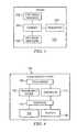
- FIG. 4illustrates an example touch-sensing device 100 that may be used in touch-sensing system 20 from FIG. 1 .
- Touch-sensing device 100includes electrode array 110 , measurement circuit 150 , controller 174 , processor 176 , receiver 180 , and memory 190 .
- electrode array 110is connected to measurement circuit 150 and controller 174 , which are both connected to processor 176 .
- Processor 176may also be connected to receiver 180 and memory 190 .
- Receiver 180may receive signals from a different medium or using different techniques from those involving electrode array 110 , described above. Some embodiments may have multiple receivers 180 , while others may not include receiver 180 .
- Touch sensor 108 and controller 174may detect the presence and location of a touch or the proximity of an object within a touch-sensitive area of touch sensor 108 .
- Touch sensor 108includes one or more touch-sensitive areas.
- touch sensor 108may include electrode array 110 (shown in FIG. 6 ).
- Electrode array 110may be a plurality of electrode lines, which may be drive and sense electrodes (or an array of electrodes of a single type), disposed on one or more substrates, which may be made of a dielectric material.
- an electrode linemay refer to a single conductive wire, a series of electrodes position in a line, or any other suitable electronic structure or series of electronic structures defining a line shape or other pattern. Such electrode lines may operate to detect finger and/or stylus position by mutual capacitance, self capacitance, induction, or any other suitable method of position detection.
- reference to an electrode arraymay encompass both the electrodes of the touch sensor as well as the substrate(s) on which they are disposed.
- An electrode(whether a ground electrode, a guard electrode, a drive electrode, or a sense electrode) may be an area of conductive material forming a shape, such as for example a disc, square, rectangle, thin line, loop, other suitable shape, or suitable combination of these.
- one or more cuts in one or more layers of conductive materialmay create the shape of an electrode, and the area of the shape may be bounded by those cuts.
- touch sensors, electrode arrays, and electrode linesmay be referred to as generating and/or sending a signal. In such cases, while the signal itself may be produced as a result of physical changes in the touch sensor or components of the touch sensor, the generation of the signal may be driven by the electrode array itself, the controller, and/or other components of touch-sensing device 100 .
- Measurement circuit 150may include circuitry configured to process signals received by electrode array 110 . The output of measurement circuit 150 may then be passed to processor 176 for further analysis, and the resulting information may be stored in memory 190 . Memory 190 also stores instructions that may be operable to, when executed by processor 176 , direct the operation of controller 174 and perform other operations. Controller 174 may be configured to control the operation of electrode array 110 . For example, controller 174 may control the generation and/or sending of signals by electrode array 110 . In some embodiments, controller 174 may control the generation and/or sending of a composite signal including a data signal and a drive signal by electrode array 110 . Controller 174 may also control the detection of signals by electrode array 110 and/or measurement circuit 150 .
- Measurement circuit 150 and controller 174may each contain multiple electronic structures on one or more chips. In some embodiments, measurement circuit 150 and controller 174 may be included in a single chip or other structure. Various operations of measurement circuit 150 and controller 174 may be controlled by hardware or by software stored in memory 190 or another memory device of touch-sensing device 100 .
- FIG. 5illustrates an example electrode array 110 that may be used in touch-sensing device 100 from FIG. 4 .
- Electrode array 100includes electrode lines 120 and electrode lines 130 .
- Electrode lines 120 and 130may be drive and/or sense lines.
- Controller 174may control the operation of electrode lines 120 and 130 such that each electrode line may operate as a drive line at one time and as a signal line at another time.
- electrode lines 120 and 130form a grid pattern, and electrode lines 120 may be orthogonal to electrode lines 130 .
- electrode lines 120 and 130may have other orientations and layouts.
- electrode lines 120may be curved, zigzagged, randomized, or have different orientations from one another, as may electrode lines 130 .
- certain embodimentsmay include multiple electrode arrays disposed in multiple layers, or electrode lines 120 may be disposed in a first layer while electrode lines 130 are disposed in a second layer.
- FIG. 6illustrates an example measurement circuit 150 that may be used in touch-sensing device 100 from FIG. 4 .
- Measurement circuit 150may process the frequency division multiplexed composite signal generated by sender 220 from FIG. 3 .
- measurement circuit 150includes electrode array connection 151 , which is connected to electrode array 110 .
- Electrode array connection 151is connected to receive channel 152 and receive channel 153 .
- Receive channel 152may be used to process the composite signal to determine the position of stylus 200 or a user's finger.
- Receive channel 153may be used to process the composite signal to determine the stylus's status information, which may include, for example, the amount of force exerted on a portion of the stylus, the orientation of the stylus, information indicating if a portion of the stylus is within a threshold distance of a portion of touch-sensing device 100 , and/or the status of a battery.
- the output of receive channels 152 and 153may be connected to processor 176 .
- Receive channels 152 and 153may allow touch-sensing device 100 to simultaneously process a composite signal received by electrode array 110 (not shown) in order to determine position information and status information in parallel. Because the signal received by the electrode lines of electrode array 110 contains both the lower frequency drive signal and the higher frequency data signal, receive channel 152 can analyze the changes in capacitance caused by the drive signal and detected at the various electrode lines of electrode array 110 in order to determine the position of stylus 200 , while receive channel 153 can analyze the higher frequency information that may be encoded in the same signal to determine the status information of stylus 200 .
- touch-sensing device 20may be able to determine the position of stylus 20 by analyzing the composite signal as a function of the first frequency and determine the information indicating the status of stylus 20 by analyzing the composite signal as a function of the second frequency.
- receive channel 152may include switch 154 , integrator 155 , ADC 160 , and signal processor 162 .
- Integrator 155includes capacitor 156 and op-amplifier 158 .
- Switch 154is connected to capacitor 156 and the inverting input of op-amplifier 158 , and the non-inverting input of op-amplifier 158 may be connected to ground 159 .
- the output of op-amplifier 158is connected to capacitor 156 and to analog-to-digital converter (ADC) 160 , which is connected to signal processor 162 .
- ADCanalog-to-digital converter
- Integrator 155may be used to detect the drive signal component of the composite signal as received by electrode array 110 , generating at its output a voltage proportional to the capacitance of one or more electrode lines of electrode array 110 .
- touching sensing devicecan determine the position of stylus 200 or a user's finger. For example, the change in capacitance is greater at intersections of electrode lines 120 and 130 that are closer to the tip of stylus 200 or a user's finger.
- touch-sensing device 100can thus determine the position of stylus 200 or a finger.
- receive channel 153may include low noise amplifier (LNA) 164 , mixer 168 , mixer input connection 166 , filter 170 , and signal processor 172 .
- Electrode array connection 151is connected to LNA 164 .
- the output of LNA 164is connected to mixer 168 , which is also connected to mixer input connection 166 .
- the output of mixer 168is connected to filter 170 , which is connected to signal processor 172 .
- Receive channel 152may be used to demodulate the data signal component of the composite signal and determine the information indicating the status of the stylus.
- the composite signalcan be processed by receive channel 153 in parallel with the processing of receive channel 152 , which may allow for greater data throughput.
- decoding the data signal in a separate channel using demodulating techniques, rather than utilizing integrator 155 to decode the data signalmay make the system less prone to noise.
- FIG. 7illustrates an example stylus 200 and electrode array 110 that may be used in touch-sensing system 20 from FIG. 1 .
- Electrode array 110has electrode lines 120 and 130 . Electrode lines 120 a and 120 b form electrode line pair 122 , and electrode lines 130 a and 130 b form electrode line pair 132 .
- Stylus 200has a position 140 with respect to electrode array 110 .
- Position 140has an X-position along dimension 142 between electrode lines 120 a and 120 b and a Y-position along dimension 144 between electrode lines 130 a and 130 b .
- Signals sent by electrode line pairs 122 and 132 , as well as other electrode line pairs formed by other electrode lines 120 and 130may be detected by stylus 200 and used to determine position 140 .
- electrode lines 120 a and 120 bmay generate and/or send quadrature signals.
- electrode lines 120 a and 120 bmay send a first signal and a second signal, respectively, each signal having the same strength and same frequency, but with the second signal having a quadrature phase shift relative to the first signal.
- Stylus 200may measure the signals sent by electrode line pair 122 , detecting the strength of the first signal and the second signal. The relative strengths of these signals, as received by stylus 200 , may be used to determine the relative distance of stylus 20 from electrode lines 120 a and 120 b and thereby determine the position of stylus 200 along dimension 142 . This same process may be done in succession by all the electrode line pairs formed by electrode lines 120 .
- this processmay be repeated with electrode line pair 132 and all other electrode line pairs formed by electrode lines 130 .
- processing quadrature signals sent by electrode line pair 122was used to determine the position of stylus 200 along dimension 142
- processing quadrature signals sent by electrode line pair 132may allow for the determination of the position of stylus 200 along dimension 144 .
- position 140 of stylus 200can be determined.
- stylus 200may have a near-field coupling mechanism so that only a limited set of signals from electrode line pairs will be received.
- stylus 200may be configured to process the quadrature signals sent by the electrode line pairs of electrode array 110 and determine its own position, which it may then communicate back to touch-sensing device 100 .
- stylus 200may be configured to detect the strengths of the received signals and communicate the strengths of the signals received from each electrode line back to touch-sensing device 100 , at which point touch-sensing device 100 may determine the position of stylus 200 based on this information.
- stylus 200may communicate this information back to touch-sensing device 100 by using a separate wireless transmitter to generate a signal that may be received by receiver 180 (not shown) of touch-sensing device 100 , or stylus 200 may communicate this information via electrode array 110 .
- Communicating the information back to touch-sensing device 100 via electrode array 110may utilize the same or similar methods to those described above for generating a data signal or a composite signal that can be detected by electrode array 110 and processed by measurement circuit 150 (not shown). For example, upon sensing quadrature signals sent by an electrode line pair of electrode array 110 , stylus 200 may determine position and/or status information based on the received signal and then combine a drive signal and a data signal including the information into a composite signal (or by otherwise encoding the information on the drive signal) which would then be received by the touch-sensing device via electrode array 110 .
- techniques other than quadrature signaling by electrode line pairsmay be utilized to allow stylus 200 to differentiate the signals received from electrode array 110 .
- information distinguishing the electrode linesmay be encoded onto the signals.
- Stylus 200would then be able to decode the information, allowing it to determine which signal was received from which electrode line.
- Using this information in conjunction with the relative strength of the received signals and/or phase shift informationmay allow the touch-sensor to operate in a finger touch mode only, with respect to sensing capacitive or inductive changes in touch sensor 108 , since stylus position could be detected by stylus 200 itself based on signals generated by the touch sensor. In other words, finger position could be directly detected by touch sensor 108 while stylus position is directly detected by stylus 200 and then communicated back to touch-sensing device 100 .
- a first electrode linesends a first signal having a first frequency
- a second electrode linesends a second signal having a second frequency.
- the second signalmay have a quadrature phase-shift relative to the first signal.
- Stylus 200receives the first signal at a first strength and receives the second signal at a second strength.
- Stylus 200sends a response signal to touch-sensing device 100 , the response signal based on the first signal and the second signal, and the position of stylus 200 is determined based on the first and the second signal.
- the position of the stylusmay be determined based at least on a difference between the first signal strength and the second signal strength.
- a third electrode linemay send a third signal having a third frequency
- a fourth electrode linemay send a fourth signal having a fourth frequency
- the first and second electrode linesmay be oriented in a first direction while the third and fourth electrode lines are oriented in a second direction, the first direction being different from the second direction.
- the first direction and the second directionmay be substantially perpendicular.
- a position along a first axismay be determined based at least on the first signal and the second signal, and a position along the second axis may be determined based at least on the third signal and the fourth signal.
- a transmitter of stylus 200may send the response signal to a wireless receiver of the touch-sensing device, or the response signal may be received by electrode array 110 .
- the position of stylus 200may be determined by stylus 200 , and the response signal may include information indicating the position of stylus 200 .
- the position of stylus 200may also be determined by touch-sensing device 100 , and the response signal may include information indicating the first strength and the second strength.
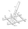
- FIG. 8illustrates example stylus 200 and electrode array 110 that may be used in touch-sensing system 20 from FIG. 1 .
- Stylus 200has a stylus position 140 with respect to electrode array 110 .
- Stylus position 140is located distance 146 from X-Y position 148 , which is an orthogonal projection of stylus position 140 onto the plane of electrode array 110 .
- X-Y position 148has an X-position along dimension 142 and a Y-position along dimension 144 .
- electrode array 110may be configured to generate and/or send signals that may be detected by stylus 200 .
- the signals sent by electrode lines 120 and 130may be encoded with information that allows stylus 200 to determine its position 140 relative to touch-sensing device 100 .
- Encoding techniquesmay include, but are not limited to, spread-spectrum techniques, closed-loop power control, and other suitable techniques for generating a data signal that is under the noise floor of capacitive, inductive, or other touch-sensing techniques described above. This may ensure that the information encoded in the signal sent by electrode array 110 does not interfere with any of the other touch-sensing operations that may be performed by touch-sensing device 100 or stylus 200 .
- electrode line 120 amay send a signal including information identifying itself as the electrode line sending the signal. This signal may also include information identifying the strength at which the signal was generated. Stylus 200 may then receive the signal sent by electrode line 120 a at a particular strength, the difference between the strength of the signal as generated and as received being proportional to the distance between electrode line 120 a and stylus 200 . This process may be repeated by electrode lines 120 b , 120 c , and other electrode lines 120 in electrode array 110 . Furthermore, the same process can be repeated with electrode lines 130 a , 130 b , and other electrode lines 130 in electrode array 110 . Thus, each electrode line 120 and 130 may send a signal to stylus 200 , each signal including information identifying which electrode line sent the signal.
- the signalmay also include information indicating the strength at which it was sent, while in other embodiments, touch-sensing device 100 may be configured to generate the signals at a known predetermined strength.
- the information identifying which electrode line sent which signal, in conjunction with the strength at which each of these signals was received by stylus 200may be used to calculate the position of stylus 200 along dimensions 142 and 144 and thus X-Y position 148 . This information may also be used to determine distance 146 and thus position 140 of stylus 200 .
- stylus 200may be configured to process the signals sent by electrode lines 120 and 130 and determine its own position, which it may then communicate back to touch-sensing device 100 .
- stylus 200may be configured to communicate the information indicating which electrode line sent each signal and the strength of each signal, as detected by stylus 200 , back to touch-sensing device 100 .
- touch-sensing device 100may then determine position 140 of stylus 200 based on this information.
- stylus 200may communicate this information back to touch-sensing device 100 by using a separate wireless transmitter to generate a signal that may be received by receiver 180 (not shown) of touch-sensing device 100 , or stylus 200 may communicate this information via electrode array 110 .
- Communicating the information back to touch-sensing device 100 via electrode array 110may utilize the same or similar methods to those described above for generating a data signal or composite signal that can be detected by electrode array 110 and processed by measurement circuit 150 (not shown).
- stylus 200may receive signals sent by electrode lines 120 and 130 , the signals encoded with information identifying which electrode line sent which signal. Stylus 200 may then send a response signal to touch-sensing device 100 via electrode array 110 based on the strength at which each signal was received and the encoded information.
- a first electrode line of an electrode arraysends a first signal including information identifying the first electrode line, the first signal having a first strength.
- the first electrode linesends the first signal to stylus 200 .
- Touch-sensing device 100then receives a received signal from stylus 200 , the received signal based at least in part on the information identifying the first electrode line and a strength at which the first signal was received by the stylus.
- the position of stylus 200is then determined based at least in part on the information identifying the first electrode line and the strength at which the first signal was received by the stylus.
- the received signalmay include information indicating the strength at which the first signal was received by stylus 200 and information identifying the first electrode line.
- the received signalmay include information indicating the position of the stylus.
- the first signalmay also include information indicating the strength at which the first signal was sent by the first electrode line, and the determination of the position of stylus 200 may be based further on the difference between the strength at which the first signal was sent by the first electrode and the strength at which the first signal was received by the stylus.
- the position of stylus 200may include a position along a first, second, and third axes, wherein the first axis is different from the second axis, the first and second axes are substantially parallel to the electrode array, and the third axis is substantially perpendicular to the electrode array.
- a second electrode line of the electrode arraymay send a second signal including information identifying the second electrode line, and determining the position of stylus 200 may be based further on the information identifying the second electrode line and a strength at which the second signal was received by stylus 200 .
- a third electrode line of the electrode arraymay send a third signal including information identifying the third electrode line, and a fourth electrode line of the electrode array may send a fourth signal including information identifying the fourth electrode line.
- the first and second electrode linesmay be oriented in a substantially similar first direction, and the third and fourth electrode lines may be oriented in a substantially similar second, the first direction being different from the second direction.
- the first direction and the second directionmay be substantially perpendicular.
- stylus 200receives a first signal including information identifying a first electrode line of an electrode array of touch-sensing device 100 , the first signal have a first received strength.
- Stylus 200analyzes the first signal to determine the first received strength and the information identifying the first electrode line.
- Stylus 200then generates a first response signal based at least in part on the first received strength and the information identifying the first electrode line and sends the first response signal to touch-sensing device 100 .
- Stylus 200may receive a second signal comprising information identifying a second electrode line of the electrode array, the second signal having a second received strength.
- the first response signalmay be based further on the second received strength and the information identifying the second electrode line, or stylus 200 may generate a second response signal based at least in part on the second received strength and the information identifying the second electrode line.
- the first signalmay further include information indicating a strength at which the first signal was sent by the first electrode line.
- the first response signalmay include the position of stylus 200 , and stylus 200 may determine its position based at least in part on the first received strength, the information identifying the first electrode line, the second received strength, and the information identifying the second electrode line
- Encoded signals generated by touch sensor 108 and received by stylus 200 with information used to determine the position of stylus 200may improve the ability of touch sensor 108 to operate without interference.
- Using methods such as spread spectrum schemes or closed-loop power controlmay allow stylus 200 to receive signals that remain below the noise floor of touch sensor 108 .
- the reduced interference of this “water-marking” signaling schememay improve the ability of finger-sensing and touch-sensing signaling to operate simultaneously.
- finger-sensing and stylus-sensing schemesmay require different signaling levels and time budgets for electrode touch sensor 108 , detecting finger position and stylus position via different pathways may improve performance of touch-sensing system 20 by obviating the need to accommodate their conflicting requirements in the same receive channel. Since design compromises caused by conflicting timing and signaling requirements of finger-sensing and stylus-sensing may be avoided, these methods may allow for improved performance of both finger-sensing and stylus-sensing.
- references in the appended claims to an apparatus or system or a component of an apparatus or system being adapted to, arranged to, capable of, configured to, enabled to, operable to, or operative to perform a particular functionencompasses that apparatus, system, component, whether or not it or that particular function is activated, turned on, or unlocked, as long as that apparatus, system, or component is so adapted, arranged, capable, configured, enabled, operable, or operative.
- touch-sensing system 20may use different types of touch-sensing device 100 and stylus 200 , and touch-sensing device 100 and stylus 200 may have different numbers and types of components, as well as different configuration and organization of those components.
- stylus 200may have different numbers and types of processor 210 , sender 220 , and receiver 260 , as well as additional components.
- electrode array 110may have different types, numbers, and orientations of electrodes lines 120 and 130 .
- electrode lines 120 and 130may form a grid of perpendicular lines, while in other embodiments, electrode lines 120 and 130 may different sizes, shapes, and orientations.
- touch-sensing system 20may utilize one or more of the communication methods described above to communicate information between touch-sensing device 100 and stylus 200 and vice versa.
- stylus 200may receive a signal from touch-sensing device 100 that includes encoded information while also sending a combined signal including a drive signal and a data signal to touch-sensing device 100 via electrode array 110 .
- stylus 200may receive quadrature signals from electrode line pairs 122 and 132 while also sending a combined signal including a drive signal and a data signal to touch-sensing device 100 via electrode array 110 .
- stylus 200may receive quadrature signals from electrode line pairs 122 and 132 , each quadrature signal encoded with information that may be used by stylus 200 to determine position and/or other information.
Landscapes
- Engineering & Computer Science (AREA)
- General Engineering & Computer Science (AREA)
- Theoretical Computer Science (AREA)
- Human Computer Interaction (AREA)
- Physics & Mathematics (AREA)
- General Physics & Mathematics (AREA)
- Position Input By Displaying (AREA)
- User Interface Of Digital Computer (AREA)
Abstract
Description
Claims (18)
Priority Applications (2)
| Application Number | Priority Date | Filing Date | Title |
|---|---|---|---|
| US13/653,300US9958966B2 (en) | 2012-10-16 | 2012-10-16 | Active stylus communication and position system |
| DE102013220920.7ADE102013220920A1 (en) | 2012-10-16 | 2013-10-16 | Active pen communication and position system |
Applications Claiming Priority (1)
| Application Number | Priority Date | Filing Date | Title |
|---|---|---|---|
| US13/653,300US9958966B2 (en) | 2012-10-16 | 2012-10-16 | Active stylus communication and position system |
Publications (2)
| Publication Number | Publication Date |
|---|---|
| US20140104188A1 US20140104188A1 (en) | 2014-04-17 |
| US9958966B2true US9958966B2 (en) | 2018-05-01 |
Family
ID=50383443
Family Applications (1)
| Application Number | Title | Priority Date | Filing Date |
|---|---|---|---|
| US13/653,300Active2034-03-13US9958966B2 (en) | 2012-10-16 | 2012-10-16 | Active stylus communication and position system |
Country Status (2)
| Country | Link |
|---|---|
| US (1) | US9958966B2 (en) |
| DE (1) | DE102013220920A1 (en) |
Families Citing this family (23)
| Publication number | Priority date | Publication date | Assignee | Title |
|---|---|---|---|---|
| US10379666B2 (en)* | 2012-05-11 | 2019-08-13 | Samsung Electronics Co., Ltd. | Position measuring apparatus, pen and position measuring method |
| US9841862B2 (en) | 2012-10-16 | 2017-12-12 | Atmel Corporation | Stylus position system |
| FR2998989B1 (en)* | 2012-12-05 | 2015-01-02 | Thales Sa | MULTITOUCHE TOUCH DEVICE WITH MULTIFREQUENCY AND BARCENTRIC CAPACITIVE DETECTION |
| US9342162B2 (en)* | 2013-01-29 | 2016-05-17 | Lg Electronics Inc. | Mobile terminal and controlling method thereof |
| KR102081817B1 (en)* | 2013-07-01 | 2020-02-26 | 삼성전자주식회사 | Method for controlling digitizer mode |
| JP2015022442A (en)* | 2013-07-17 | 2015-02-02 | 株式会社東芝 | Electronic device, control method of electronic device, and control program of electronic device |
| US20150054783A1 (en)* | 2013-08-22 | 2015-02-26 | Microchip Technology Incorporated | Touch Screen Stylus with Communication Interface |
| JP6487694B2 (en)* | 2014-12-26 | 2019-03-20 | 株式会社ワコム | Position indicator and signal processing device |
| CN107111390B (en) | 2015-01-04 | 2021-04-16 | 微软技术许可有限责任公司 | Method and system for active stylus to digitizer communication |
| CN107111388B (en) | 2015-01-04 | 2020-06-05 | 微软技术许可有限责任公司 | Method and apparatus for communicating with a universal stylus of a digitizer |
| US9977519B2 (en)* | 2015-02-25 | 2018-05-22 | Synaptics Incorporated | Active pen with bidirectional communication |
| KR102333720B1 (en) | 2015-04-09 | 2021-12-01 | 삼성전자주식회사 | Digital Pen, Touch System, and Method for providing information thereof |
| US10955977B2 (en) | 2015-11-03 | 2021-03-23 | Microsoft Technology Licensing, Llc | Extender object for multi-modal sensing |
| US9933891B2 (en)* | 2015-11-03 | 2018-04-03 | Microsoft Technology Licensing, Llc | User input comprising an event and detected motion |
| US10649572B2 (en) | 2015-11-03 | 2020-05-12 | Microsoft Technology Licensing, Llc | Multi-modal sensing surface |
| US10338753B2 (en) | 2015-11-03 | 2019-07-02 | Microsoft Technology Licensing, Llc | Flexible multi-layer sensing surface |
| US10671186B2 (en)* | 2016-06-15 | 2020-06-02 | Microsoft Technology Licensing, Llc | Autonomous haptic stylus |
| TWI648660B (en)* | 2017-07-31 | 2019-01-21 | Waltop International Corporation | Capacitive pen that provides tilt angle and azimuth detection signals |
| TWI630513B (en)* | 2017-08-04 | 2018-07-21 | Waltop International Corporation | Capacitive stylus providing signals for tilt and orientation detection |
| WO2019113906A1 (en)* | 2017-12-14 | 2019-06-20 | 深圳市汇顶科技股份有限公司 | Method and apparatus for determining coordinates of stylus, electronic device and storage medium |
| KR102468750B1 (en)* | 2017-12-29 | 2022-11-18 | 엘지디스플레이 주식회사 | Touch display device, touch system, touch driving circuit, and pen sensing method |
| US10983642B2 (en)* | 2018-07-30 | 2021-04-20 | Texas Instruments Incorporated | Using driven shield and touch elements lock algorithm for achieving liquid tolerant capacitive touch solution |
| KR102573727B1 (en)* | 2018-08-08 | 2023-09-04 | 삼성전자주식회사 | Electronic device and method for recognizing stylus pen |
Citations (37)
| Publication number | Priority date | Publication date | Assignee | Title |
|---|---|---|---|---|
| US5194852A (en) | 1986-12-01 | 1993-03-16 | More Edward S | Electro-optic slate for direct entry and display and/or storage of hand-entered textual and graphic information |
| US20070109274A1 (en) | 2005-11-15 | 2007-05-17 | Synaptics Incorporated | Methods and systems for detecting a position-based attribute of an object using digital codes |
| US20080158165A1 (en)* | 2006-12-28 | 2008-07-03 | 3M Innovative Properties Company | Location sensing system and method employing adaptive drive signal adjustment |
| US20080158167A1 (en) | 2007-01-03 | 2008-07-03 | Apple Computer, Inc. | Simultaneous sensing arrangement |
| US20080309635A1 (en) | 2007-06-14 | 2008-12-18 | Epson Imaging Devices Corporation | Capacitive input device |
| US20090153500A1 (en) | 2007-12-17 | 2009-06-18 | Samsung Electronics Co., Ltd. | Dual pointing device and method based on 3-D motion and touch sensors |
| US20090315854A1 (en) | 2008-06-18 | 2009-12-24 | Epson Imaging Devices Corporation | Capacitance type input device and display device with input function |
| US7663607B2 (en) | 2004-05-06 | 2010-02-16 | Apple Inc. | Multipoint touchscreen |
| US20100155153A1 (en)* | 2008-12-22 | 2010-06-24 | N-Trig Ltd. | Digitizer, stylus and method of synchronization therewith |
| US7864503B2 (en) | 2007-05-11 | 2011-01-04 | Sense Pad Tech Co., Ltd | Capacitive type touch panel |
| US7875814B2 (en) | 2005-07-21 | 2011-01-25 | Tpo Displays Corp. | Electromagnetic digitizer sensor array structure |
| US20110063993A1 (en) | 2009-09-11 | 2011-03-17 | Thomas James Wilson | Automatic Low Noise Frequency Selection |
| US7920129B2 (en) | 2007-01-03 | 2011-04-05 | Apple Inc. | Double-sided touch-sensitive panel with shield and drive combined layer |
| US20110084857A1 (en) | 2009-10-08 | 2011-04-14 | 3M Innovative Properties Company | Multi-touch touch device with multiple drive frequencies and maximum likelihood estimation |
| US20110175834A1 (en) | 2010-01-15 | 2011-07-21 | Samsung Electronics Co., Ltd. | Touch panel and input recognition device using the touch panel |
| US8031174B2 (en) | 2007-01-03 | 2011-10-04 | Apple Inc. | Multi-touch surface stackup arrangement |
| US8031094B2 (en) | 2009-09-11 | 2011-10-04 | Apple Inc. | Touch controller with improved analog front end |
| US8040326B2 (en) | 2007-06-13 | 2011-10-18 | Apple Inc. | Integrated in-plane switching display and touch sensor |
| US8049732B2 (en) | 2007-01-03 | 2011-11-01 | Apple Inc. | Front-end signal compensation |
| US20120044192A1 (en) | 2010-08-20 | 2012-02-23 | Chao-Yong Hsu | Touch control system with multi-touch detection functions |
| US20120050207A1 (en)* | 2010-08-30 | 2012-03-01 | Perceptive Pixel Inc. | Localizing an Electrostatic Stylus Within a Capacitive Touch Sensor |
| US20120105362A1 (en)* | 2010-10-28 | 2012-05-03 | Cypress Semiconductor Corporation | Synchronizing a stylus with a capacitive sense array |
| US8179381B2 (en) | 2008-02-28 | 2012-05-15 | 3M Innovative Properties Company | Touch screen sensor |
| US8217902B2 (en) | 2007-04-27 | 2012-07-10 | Tpk Touch Solutions Inc. | Conductor pattern structure of capacitive touch panel |
| US20120243719A1 (en) | 2011-03-21 | 2012-09-27 | Franklin Jeremy C | Display-Based Speaker Structures for Electronic Devices |
| US20120243151A1 (en) | 2011-03-21 | 2012-09-27 | Stephen Brian Lynch | Electronic Devices With Convex Displays |
| WO2012129247A2 (en) | 2011-03-21 | 2012-09-27 | Apple Inc. | Electronic devices with flexible displays |
| US20120242588A1 (en) | 2011-03-21 | 2012-09-27 | Myers Scott A | Electronic devices with concave displays |
| US20120242592A1 (en) | 2011-03-21 | 2012-09-27 | Rothkopf Fletcher R | Electronic devices with flexible displays |
| US20120327042A1 (en) | 2011-06-22 | 2012-12-27 | Harley Jonah A | Stylus orientation detection |
| US20120327041A1 (en)* | 2011-06-22 | 2012-12-27 | Harley Jonah A | Active stylus |
| US20130076612A1 (en) | 2011-09-26 | 2013-03-28 | Apple Inc. | Electronic device with wrap around display |
| US20130106798A1 (en)* | 2011-10-28 | 2013-05-02 | Atmel Corporation | Differential Sensing in an Active Stylus |
| US20140049478A1 (en)* | 2012-08-15 | 2014-02-20 | Samuel Brunet | Active stylus with passive mutual measurements |
| US20140104187A1 (en) | 2012-10-16 | 2014-04-17 | Vemund Kval Bakken | Stylus Position System |
| US20140111464A1 (en) | 2012-10-18 | 2014-04-24 | Vemund Kval Bakken | Touch Sensor With Simultaneously Driven Drive Electrodes |
| US8723824B2 (en) | 2011-09-27 | 2014-05-13 | Apple Inc. | Electronic devices with sidewall displays |
- 2012
- 2012-10-16USUS13/653,300patent/US9958966B2/enactiveActive
- 2013
- 2013-10-16DEDE102013220920.7Apatent/DE102013220920A1/ennot_activeWithdrawn
Patent Citations (38)
| Publication number | Priority date | Publication date | Assignee | Title |
|---|---|---|---|---|
| US5194852A (en) | 1986-12-01 | 1993-03-16 | More Edward S | Electro-optic slate for direct entry and display and/or storage of hand-entered textual and graphic information |
| US7663607B2 (en) | 2004-05-06 | 2010-02-16 | Apple Inc. | Multipoint touchscreen |
| US7875814B2 (en) | 2005-07-21 | 2011-01-25 | Tpo Displays Corp. | Electromagnetic digitizer sensor array structure |
| US20070109274A1 (en) | 2005-11-15 | 2007-05-17 | Synaptics Incorporated | Methods and systems for detecting a position-based attribute of an object using digital codes |
| US20080158165A1 (en)* | 2006-12-28 | 2008-07-03 | 3M Innovative Properties Company | Location sensing system and method employing adaptive drive signal adjustment |
| US7920129B2 (en) | 2007-01-03 | 2011-04-05 | Apple Inc. | Double-sided touch-sensitive panel with shield and drive combined layer |
| US20080158167A1 (en) | 2007-01-03 | 2008-07-03 | Apple Computer, Inc. | Simultaneous sensing arrangement |
| US8049732B2 (en) | 2007-01-03 | 2011-11-01 | Apple Inc. | Front-end signal compensation |
| US8031174B2 (en) | 2007-01-03 | 2011-10-04 | Apple Inc. | Multi-touch surface stackup arrangement |
| US7812827B2 (en) | 2007-01-03 | 2010-10-12 | Apple Inc. | Simultaneous sensing arrangement |
| US8217902B2 (en) | 2007-04-27 | 2012-07-10 | Tpk Touch Solutions Inc. | Conductor pattern structure of capacitive touch panel |
| US7864503B2 (en) | 2007-05-11 | 2011-01-04 | Sense Pad Tech Co., Ltd | Capacitive type touch panel |
| US8040326B2 (en) | 2007-06-13 | 2011-10-18 | Apple Inc. | Integrated in-plane switching display and touch sensor |
| US20080309635A1 (en) | 2007-06-14 | 2008-12-18 | Epson Imaging Devices Corporation | Capacitive input device |
| US20090153500A1 (en) | 2007-12-17 | 2009-06-18 | Samsung Electronics Co., Ltd. | Dual pointing device and method based on 3-D motion and touch sensors |
| US8179381B2 (en) | 2008-02-28 | 2012-05-15 | 3M Innovative Properties Company | Touch screen sensor |
| US20090315854A1 (en) | 2008-06-18 | 2009-12-24 | Epson Imaging Devices Corporation | Capacitance type input device and display device with input function |
| US20100155153A1 (en)* | 2008-12-22 | 2010-06-24 | N-Trig Ltd. | Digitizer, stylus and method of synchronization therewith |
| US20110063993A1 (en) | 2009-09-11 | 2011-03-17 | Thomas James Wilson | Automatic Low Noise Frequency Selection |
| US8031094B2 (en) | 2009-09-11 | 2011-10-04 | Apple Inc. | Touch controller with improved analog front end |
| US20110084857A1 (en) | 2009-10-08 | 2011-04-14 | 3M Innovative Properties Company | Multi-touch touch device with multiple drive frequencies and maximum likelihood estimation |
| US20110175834A1 (en) | 2010-01-15 | 2011-07-21 | Samsung Electronics Co., Ltd. | Touch panel and input recognition device using the touch panel |
| US20120044192A1 (en) | 2010-08-20 | 2012-02-23 | Chao-Yong Hsu | Touch control system with multi-touch detection functions |
| US20120050207A1 (en)* | 2010-08-30 | 2012-03-01 | Perceptive Pixel Inc. | Localizing an Electrostatic Stylus Within a Capacitive Touch Sensor |
| US20120105362A1 (en)* | 2010-10-28 | 2012-05-03 | Cypress Semiconductor Corporation | Synchronizing a stylus with a capacitive sense array |
| US20120243719A1 (en) | 2011-03-21 | 2012-09-27 | Franklin Jeremy C | Display-Based Speaker Structures for Electronic Devices |
| US20120243151A1 (en) | 2011-03-21 | 2012-09-27 | Stephen Brian Lynch | Electronic Devices With Convex Displays |
| WO2012129247A2 (en) | 2011-03-21 | 2012-09-27 | Apple Inc. | Electronic devices with flexible displays |
| US20120242588A1 (en) | 2011-03-21 | 2012-09-27 | Myers Scott A | Electronic devices with concave displays |
| US20120242592A1 (en) | 2011-03-21 | 2012-09-27 | Rothkopf Fletcher R | Electronic devices with flexible displays |
| US20120327042A1 (en) | 2011-06-22 | 2012-12-27 | Harley Jonah A | Stylus orientation detection |
| US20120327041A1 (en)* | 2011-06-22 | 2012-12-27 | Harley Jonah A | Active stylus |
| US20130076612A1 (en) | 2011-09-26 | 2013-03-28 | Apple Inc. | Electronic device with wrap around display |
| US8723824B2 (en) | 2011-09-27 | 2014-05-13 | Apple Inc. | Electronic devices with sidewall displays |
| US20130106798A1 (en)* | 2011-10-28 | 2013-05-02 | Atmel Corporation | Differential Sensing in an Active Stylus |
| US20140049478A1 (en)* | 2012-08-15 | 2014-02-20 | Samuel Brunet | Active stylus with passive mutual measurements |
| US20140104187A1 (en) | 2012-10-16 | 2014-04-17 | Vemund Kval Bakken | Stylus Position System |
| US20140111464A1 (en) | 2012-10-18 | 2014-04-24 | Vemund Kval Bakken | Touch Sensor With Simultaneously Driven Drive Electrodes |
Non-Patent Citations (30)
| Title |
|---|
| Bakken et al., U.S. Appl. No. 13/653,247, Advisory Action, dated Sep. 28, 2016. |
| Bakken et al., U.S. Appl. No. 13/653,247, Final Office Action, dated Apr. 14, 2017. |
| Bakken et al., U.S. Appl. No. 13/653,247, Final Office Action, dated Jul. 12, 2016. |
| Bakken et al., U.S. Appl. No. 13/653,247, Final Office Action, dated Jul. 15, 2015. |
| Bakken et al., U.S. Appl. No. 13/653,247, Final Office Action, dated Oct. 29, 2014. |
| Bakken et al., U.S. Appl. No. 13/653,247, Non-Final Office Action, dated Dec. 8, 2016. |
| Bakken et al., U.S. Appl. No. 13/653,247, Non-final Office Action, dated Jun. 20, 2014. |
| Bakken et al., U.S. Appl. No. 13/653,247, Non-final Office Action, dated Mar. 12, 2015. |
| Bakken et al., U.S. Appl. No. 13/653,247, Request for Continued Examination and Amendment, dated Jan. 30, 2015. |
| Bakken et al., U.S. Appl. No. 13/653,247, Request for Continued Examination and Amendment, dated Oct. 12, 2016. |
| Bakken et al., U.S. Appl. No. 13/653,247, Response Non-final Office Action, dated Jun. 12, 2015. |
| Bakken et al., U.S. Appl. No. 13/653,247, Response Non-final Office Action, dated Sep. 22, 2014. |
| Bakken et al., U.S. Appl. No. 13/653,247, Response to Final Office Action, dated Sep. 12, 2016. |
| Bakken et al., U.S. Appl. No. 13/653,247, Response to Non-Final Office Action, dated Mar. 8, 2017. |
| Bakken et al., U.S. Appl. No. 13/654,996, Final Office Action, dated Mar. 25, 2015. |
| Bakken et al., U.S. Appl. No. 13/654,996, Non-final Office Action, dated Aug. 27, 2015. |
| Bakken et al., U.S. Appl. No. 13/654,996, Non-Final Office Action, dated Jul. 31, 2014. |
| Bakken et al., U.S. Appl. No. 13/654,996, Non-Final Office Action, dated Nov. 30, 2016. |
| Bakken et al., U.S. Appl. No. 13/654,996, Request for Continued Examination and Amendment, dated Nov. 1, 2016. |
| Bakken et al., U.S. Appl. No. 13/654,996, Request for Continued Examination and Response, dated Jun. 25, 2015. |
| Bakken et al., U.S. Appl. No. 13/654,996, Response to Non-final Office Action, dated Dec. 1, 2014. |
| Bakken et al., U.S. Appl. No. 13/654,996, Response to Non-Final Office Action, dated May 30, 2017. |
| U.S. Appl. No. 61/454,894, filed Mar. 21, 2011, Rothkopf. |
| U.S. Appl. No. 61/454,936, filed Mar. 21, 2011, Myers. |
| U.S. Appl. No. 61/454,950, filed Mar. 21, 2011, Lynch. |
| V. K. Bakken et al., U.S. Appl. No. 13/653,247, Non-Final Office Action dated Feb. 29, 2016. |
| V. K. Bakken et al., U.S. Appl. No. 13/653,247, RCE and Amendment filed Jan. 14, 2016. |
| V. K. Bakken et al., U.S. Appl. No. 13/653,247, Response to Non-Final Office Action filed May 26, 2016. |
| V. K. Bakken et al., U.S. Appl. No. 13/654,996, Final Office Action dated May 2, 2016. |
| V. K. Bakken et al., U.S. Appl. No. 13/654,996, Response to NFOA filed Jan. 27, 2016. |
Also Published As
| Publication number | Publication date |
|---|---|
| US20140104188A1 (en) | 2014-04-17 |
| DE102013220920A1 (en) | 2014-04-17 |
Similar Documents
| Publication | Publication Date | Title |
|---|---|---|
| US9958966B2 (en) | Active stylus communication and position system | |
| US9841862B2 (en) | Stylus position system | |
| US10031590B2 (en) | Active stylus with a parallel communication channel | |
| US8493359B2 (en) | Capacitive stylus for a touch screen | |
| US9658720B2 (en) | Capacitive sense array for detecting passive touch objects and an active stylus | |
| US9454272B2 (en) | Touch screen for stylus emitting wireless signals | |
| US8766949B2 (en) | Systems and methods for determining user input using simultaneous transmission from multiple electrodes | |
| CN111538422B (en) | Activation pen and input system | |
| CN104731424B (en) | Method, device and system for detecting sender close to touch device | |
| CN108055870A (en) | Semi-passive stylus | |
| US20120326910A1 (en) | System and method for signaling in sensor devices | |
| TWI514205B (en) | Transmitter, touch sensitive system and transmitting method thereof | |
| US10203809B2 (en) | Interference detection | |
| US8907913B2 (en) | Backscatter stylus for use with touchscreen | |
| US12204716B2 (en) | Capacitive communication channel for auxiliary devices |
Legal Events
| Date | Code | Title | Description |
|---|---|---|---|
| AS | Assignment | Owner name:ATMEL CORPORATION, CALIFORNIA Free format text:ASSIGNMENT OF ASSIGNORS INTEREST;ASSIGNORS:BAKKEN, VEMUND KVAL;BENTOV, IZHAR;PANT, VIVEK;SIGNING DATES FROM 20121012 TO 20121015;REEL/FRAME:029139/0901 | |
| AS | Assignment | Owner name:MORGAN STANLEY SENIOR FUNDING, INC. AS ADMINISTRATIVE AGENT, NEW YORK Free format text:PATENT SECURITY AGREEMENT;ASSIGNOR:ATMEL CORPORATION;REEL/FRAME:031912/0173 Effective date:20131206 Owner name:MORGAN STANLEY SENIOR FUNDING, INC. AS ADMINISTRAT Free format text:PATENT SECURITY AGREEMENT;ASSIGNOR:ATMEL CORPORATION;REEL/FRAME:031912/0173 Effective date:20131206 | |
| AS | Assignment | Owner name:ATMEL CORPORATION, CALIFORNIA Free format text:TERMINATION AND RELEASE OF SECURITY INTEREST IN PATENT COLLATERAL;ASSIGNOR:MORGAN STANLEY SENIOR FUNDING, INC.;REEL/FRAME:038376/0001 Effective date:20160404 | |
| AS | Assignment | Owner name:JPMORGAN CHASE BANK, N.A., AS ADMINISTRATIVE AGENT, ILLINOIS Free format text:SECURITY INTEREST;ASSIGNOR:ATMEL CORPORATION;REEL/FRAME:041715/0747 Effective date:20170208 Owner name:JPMORGAN CHASE BANK, N.A., AS ADMINISTRATIVE AGENT Free format text:SECURITY INTEREST;ASSIGNOR:ATMEL CORPORATION;REEL/FRAME:041715/0747 Effective date:20170208 | |
| STCF | Information on status: patent grant | Free format text:PATENTED CASE | |
| AS | Assignment | Owner name:JPMORGAN CHASE BANK, N.A., AS ADMINISTRATIVE AGENT, ILLINOIS Free format text:SECURITY INTEREST;ASSIGNORS:MICROCHIP TECHNOLOGY INCORPORATED;SILICON STORAGE TECHNOLOGY, INC.;ATMEL CORPORATION;AND OTHERS;REEL/FRAME:046426/0001 Effective date:20180529 Owner name:JPMORGAN CHASE BANK, N.A., AS ADMINISTRATIVE AGENT Free format text:SECURITY INTEREST;ASSIGNORS:MICROCHIP TECHNOLOGY INCORPORATED;SILICON STORAGE TECHNOLOGY, INC.;ATMEL CORPORATION;AND OTHERS;REEL/FRAME:046426/0001 Effective date:20180529 | |
| AS | Assignment | Owner name:WELLS FARGO BANK, NATIONAL ASSOCIATION, AS NOTES COLLATERAL AGENT, CALIFORNIA Free format text:SECURITY INTEREST;ASSIGNORS:MICROCHIP TECHNOLOGY INCORPORATED;SILICON STORAGE TECHNOLOGY, INC.;ATMEL CORPORATION;AND OTHERS;REEL/FRAME:047103/0206 Effective date:20180914 Owner name:WELLS FARGO BANK, NATIONAL ASSOCIATION, AS NOTES C Free format text:SECURITY INTEREST;ASSIGNORS:MICROCHIP TECHNOLOGY INCORPORATED;SILICON STORAGE TECHNOLOGY, INC.;ATMEL CORPORATION;AND OTHERS;REEL/FRAME:047103/0206 Effective date:20180914 | |
| AS | Assignment | Owner name:SILICON STORAGE TECHNOLOGY, INC., ARIZONA Free format text:RELEASE OF SECURITY INTEREST IN CERTAIN PATENT RIGHTS;ASSIGNOR:JPMORGAN CHASE BANK, N.A., AS ADMINISTRATIVE AGENT;REEL/FRAME:047158/0958 Effective date:20180927 Owner name:MICROSEMI CORPORATION, ARIZONA Free format text:RELEASE OF SECURITY INTEREST IN CERTAIN PATENT RIGHTS;ASSIGNOR:JPMORGAN CHASE BANK, N.A., AS ADMINISTRATIVE AGENT;REEL/FRAME:047158/0958 Effective date:20180927 Owner name:ATMEL CORPORATION, ARIZONA Free format text:RELEASE OF SECURITY INTEREST IN CERTAIN PATENT RIGHTS;ASSIGNOR:JPMORGAN CHASE BANK, N.A., AS ADMINISTRATIVE AGENT;REEL/FRAME:047158/0958 Effective date:20180927 Owner name:MICROCHIP TECHNOLOGY INCORPORATED, ARIZONA Free format text:RELEASE OF SECURITY INTEREST IN CERTAIN PATENT RIGHTS;ASSIGNOR:JPMORGAN CHASE BANK, N.A., AS ADMINISTRATIVE AGENT;REEL/FRAME:047158/0958 Effective date:20180927 Owner name:MICROSEMI STORAGE SOLUTIONS, INC., ARIZONA Free format text:RELEASE OF SECURITY INTEREST IN CERTAIN PATENT RIGHTS;ASSIGNOR:JPMORGAN CHASE BANK, N.A., AS ADMINISTRATIVE AGENT;REEL/FRAME:047158/0958 Effective date:20180927 Owner name:MICROSEMI STORAGE SOLUTIONS, INC., ARIZONA Free format text:RELEASE OF SECURITY INTEREST IN CERTAIN PATENT RIGHTS;ASSIGNOR:WELLS FARGO BANK, NATIONAL ASSOCIATION, AS NOTES COLLATERAL AGENT;REEL/FRAME:047159/0792 Effective date:20180927 Owner name:ATMEL CORPORATION, ARIZONA Free format text:RELEASE OF SECURITY INTEREST IN CERTAIN PATENT RIGHTS;ASSIGNOR:WELLS FARGO BANK, NATIONAL ASSOCIATION, AS NOTES COLLATERAL AGENT;REEL/FRAME:047159/0792 Effective date:20180927 Owner name:MICROSEMI CORPORATION, ARIZONA Free format text:RELEASE OF SECURITY INTEREST IN CERTAIN PATENT RIGHTS;ASSIGNOR:WELLS FARGO BANK, NATIONAL ASSOCIATION, AS NOTES COLLATERAL AGENT;REEL/FRAME:047159/0792 Effective date:20180927 Owner name:SILICON STORAGE TECHNOLOGY, INC., ARIZONA Free format text:RELEASE OF SECURITY INTEREST IN CERTAIN PATENT RIGHTS;ASSIGNOR:WELLS FARGO BANK, NATIONAL ASSOCIATION, AS NOTES COLLATERAL AGENT;REEL/FRAME:047159/0792 Effective date:20180927 Owner name:MICROCHIP TECHNOLOGY INCORPORATED, ARIZONA Free format text:RELEASE OF SECURITY INTEREST IN CERTAIN PATENT RIGHTS;ASSIGNOR:WELLS FARGO BANK, NATIONAL ASSOCIATION, AS NOTES COLLATERAL AGENT;REEL/FRAME:047159/0792 Effective date:20180927 | |
| AS | Assignment | Owner name:WACOM CO., LTD., JAPAN Free format text:ASSIGNMENT OF ASSIGNORS INTEREST;ASSIGNOR:ATMEL CORPORATION;REEL/FRAME:047640/0227 Effective date:20180925 | |
| MAFP | Maintenance fee payment | Free format text:PAYMENT OF MAINTENANCE FEE, 4TH YEAR, LARGE ENTITY (ORIGINAL EVENT CODE: M1551); ENTITY STATUS OF PATENT OWNER: LARGE ENTITY Year of fee payment:4 | |
| AS | Assignment | Owner name:MICROSEMI STORAGE SOLUTIONS, INC., ARIZONA Free format text:RELEASE BY SECURED PARTY;ASSIGNOR:JPMORGAN CHASE BANK, N.A., AS ADMINISTRATIVE AGENT;REEL/FRAME:059333/0222 Effective date:20220218 Owner name:MICROSEMI CORPORATION, ARIZONA Free format text:RELEASE BY SECURED PARTY;ASSIGNOR:JPMORGAN CHASE BANK, N.A., AS ADMINISTRATIVE AGENT;REEL/FRAME:059333/0222 Effective date:20220218 Owner name:ATMEL CORPORATION, ARIZONA Free format text:RELEASE BY SECURED PARTY;ASSIGNOR:JPMORGAN CHASE BANK, N.A., AS ADMINISTRATIVE AGENT;REEL/FRAME:059333/0222 Effective date:20220218 Owner name:SILICON STORAGE TECHNOLOGY, INC., ARIZONA Free format text:RELEASE BY SECURED PARTY;ASSIGNOR:JPMORGAN CHASE BANK, N.A., AS ADMINISTRATIVE AGENT;REEL/FRAME:059333/0222 Effective date:20220218 Owner name:MICROCHIP TECHNOLOGY INCORPORATED, ARIZONA Free format text:RELEASE BY SECURED PARTY;ASSIGNOR:JPMORGAN CHASE BANK, N.A., AS ADMINISTRATIVE AGENT;REEL/FRAME:059333/0222 Effective date:20220218 | |
| AS | Assignment | Owner name:ATMEL CORPORATION, ARIZONA Free format text:RELEASE BY SECURED PARTY;ASSIGNOR:JPMORGAN CHASE BANK, N.A., AS ADMINISTRATIVE AGENT;REEL/FRAME:059262/0105 Effective date:20220218 | |
| AS | Assignment | Owner name:MICROSEMI STORAGE SOLUTIONS, INC., ARIZONA Free format text:RELEASE BY SECURED PARTY;ASSIGNOR:WELLS FARGO BANK, NATIONAL ASSOCIATION, AS NOTES COLLATERAL AGENT;REEL/FRAME:059358/0001 Effective date:20220228 Owner name:MICROSEMI CORPORATION, ARIZONA Free format text:RELEASE BY SECURED PARTY;ASSIGNOR:WELLS FARGO BANK, NATIONAL ASSOCIATION, AS NOTES COLLATERAL AGENT;REEL/FRAME:059358/0001 Effective date:20220228 Owner name:ATMEL CORPORATION, ARIZONA Free format text:RELEASE BY SECURED PARTY;ASSIGNOR:WELLS FARGO BANK, NATIONAL ASSOCIATION, AS NOTES COLLATERAL AGENT;REEL/FRAME:059358/0001 Effective date:20220228 Owner name:SILICON STORAGE TECHNOLOGY, INC., ARIZONA Free format text:RELEASE BY SECURED PARTY;ASSIGNOR:WELLS FARGO BANK, NATIONAL ASSOCIATION, AS NOTES COLLATERAL AGENT;REEL/FRAME:059358/0001 Effective date:20220228 Owner name:MICROCHIP TECHNOLOGY INCORPORATED, ARIZONA Free format text:RELEASE BY SECURED PARTY;ASSIGNOR:WELLS FARGO BANK, NATIONAL ASSOCIATION, AS NOTES COLLATERAL AGENT;REEL/FRAME:059358/0001 Effective date:20220228 |