US9958858B2 - Associating computer-executable objects with three-dimensional spaces within an architectural design environment - Google Patents
Associating computer-executable objects with three-dimensional spaces within an architectural design environmentDownload PDFInfo
- Publication number
- US9958858B2 US9958858B2US14/115,299US201314115299AUS9958858B2US 9958858 B2US9958858 B2US 9958858B2US 201314115299 AUS201314115299 AUS 201314115299AUS 9958858 B2US9958858 B2US 9958858B2
- Authority
- US
- United States
- Prior art keywords
- framework
- independent cell
- manufacturing
- spatial framework
- architectural
- Prior art date
- Legal status (The legal status is an assumption and is not a legal conclusion. Google has not performed a legal analysis and makes no representation as to the accuracy of the status listed.)
- Active
Links
Images


Classifications
- G—PHYSICS
- G05—CONTROLLING; REGULATING
- G05B—CONTROL OR REGULATING SYSTEMS IN GENERAL; FUNCTIONAL ELEMENTS OF SUCH SYSTEMS; MONITORING OR TESTING ARRANGEMENTS FOR SUCH SYSTEMS OR ELEMENTS
- G05B19/00—Programme-control systems
- G05B19/02—Programme-control systems electric
- G05B19/18—Numerical control [NC], i.e. automatically operating machines, in particular machine tools, e.g. in a manufacturing environment, so as to execute positioning, movement or co-ordinated operations by means of programme data in numerical form
- G05B19/4097—Numerical control [NC], i.e. automatically operating machines, in particular machine tools, e.g. in a manufacturing environment, so as to execute positioning, movement or co-ordinated operations by means of programme data in numerical form characterised by using design data to control NC machines, e.g. CAD/CAM
- G06F17/5004—
- G—PHYSICS
- G06—COMPUTING OR CALCULATING; COUNTING
- G06F—ELECTRIC DIGITAL DATA PROCESSING
- G06F30/00—Computer-aided design [CAD]
- G06F30/10—Geometric CAD
- G06F30/13—Architectural design, e.g. computer-aided architectural design [CAAD] related to design of buildings, bridges, landscapes, production plants or roads
- G—PHYSICS
- G05—CONTROLLING; REGULATING
- G05B—CONTROL OR REGULATING SYSTEMS IN GENERAL; FUNCTIONAL ELEMENTS OF SUCH SYSTEMS; MONITORING OR TESTING ARRANGEMENTS FOR SUCH SYSTEMS OR ELEMENTS
- G05B2219/00—Program-control systems
- G05B2219/30—Nc systems
- G05B2219/35—Nc in input of data, input till input file format
- G05B2219/35003—Kad kam knowledge aided design, knowledge aided manufacturing
- G—PHYSICS
- G05—CONTROLLING; REGULATING
- G05B—CONTROL OR REGULATING SYSTEMS IN GENERAL; FUNCTIONAL ELEMENTS OF SUCH SYSTEMS; MONITORING OR TESTING ARRANGEMENTS FOR SUCH SYSTEMS OR ELEMENTS
- G05B2219/00—Program-control systems
- G05B2219/30—Nc systems
- G05B2219/35—Nc in input of data, input till input file format
- G05B2219/35023—Constraint based modeling, keep relationships between elements
- G—PHYSICS
- G05—CONTROLLING; REGULATING
- G05B—CONTROL OR REGULATING SYSTEMS IN GENERAL; FUNCTIONAL ELEMENTS OF SUCH SYSTEMS; MONITORING OR TESTING ARRANGEMENTS FOR SUCH SYSTEMS OR ELEMENTS
- G05B2219/00—Program-control systems
- G05B2219/30—Nc systems
- G05B2219/35—Nc in input of data, input till input file format
- G05B2219/35028—Adapt design as function of manufacturing merits, features, for manufacturing, DFM
- G—PHYSICS
- G05—CONTROLLING; REGULATING
- G05B—CONTROL OR REGULATING SYSTEMS IN GENERAL; FUNCTIONAL ELEMENTS OF SUCH SYSTEMS; MONITORING OR TESTING ARRANGEMENTS FOR SUCH SYSTEMS OR ELEMENTS
- G05B2219/00—Program-control systems
- G05B2219/30—Nc systems
- G05B2219/35—Nc in input of data, input till input file format
- G05B2219/35031—Redesign, use former design
- G—PHYSICS
- G05—CONTROLLING; REGULATING
- G05B—CONTROL OR REGULATING SYSTEMS IN GENERAL; FUNCTIONAL ELEMENTS OF SUCH SYSTEMS; MONITORING OR TESTING ARRANGEMENTS FOR SUCH SYSTEMS OR ELEMENTS
- G05B2219/00—Program-control systems
- G05B2219/30—Nc systems
- G05B2219/35—Nc in input of data, input till input file format
- G05B2219/35051—Data exchange between cad systems, cad and cam
- G—PHYSICS
- G05—CONTROLLING; REGULATING
- G05B—CONTROL OR REGULATING SYSTEMS IN GENERAL; FUNCTIONAL ELEMENTS OF SUCH SYSTEMS; MONITORING OR TESTING ARRANGEMENTS FOR SUCH SYSTEMS OR ELEMENTS
- G05B2219/00—Program-control systems
- G05B2219/30—Nc systems
- G05B2219/35—Nc in input of data, input till input file format
- G05B2219/35134—3-D cad-cam
- G—PHYSICS
- G06—COMPUTING OR CALCULATING; COUNTING
- G06F—ELECTRIC DIGITAL DATA PROCESSING
- G06F2111/00—Details relating to CAD techniques
- G06F2111/04—Constraint-based CAD
- G—PHYSICS
- G06—COMPUTING OR CALCULATING; COUNTING
- G06F—ELECTRIC DIGITAL DATA PROCESSING
- G06F2111/00—Details relating to CAD techniques
- G06F2111/20—Configuration CAD, e.g. designing by assembling or positioning modules selected from libraries of predesigned modules
- G—PHYSICS
- G06—COMPUTING OR CALCULATING; COUNTING
- G06F—ELECTRIC DIGITAL DATA PROCESSING
- G06F2119/00—Details relating to the type or aim of the analysis or the optimisation
- G06F2119/18—Manufacturability analysis or optimisation for manufacturability
- G06F2217/02—
- G06F2217/06—
- G06F2217/12—
- Y—GENERAL TAGGING OF NEW TECHNOLOGICAL DEVELOPMENTS; GENERAL TAGGING OF CROSS-SECTIONAL TECHNOLOGIES SPANNING OVER SEVERAL SECTIONS OF THE IPC; TECHNICAL SUBJECTS COVERED BY FORMER USPC CROSS-REFERENCE ART COLLECTIONS [XRACs] AND DIGESTS
- Y02—TECHNOLOGIES OR APPLICATIONS FOR MITIGATION OR ADAPTATION AGAINST CLIMATE CHANGE
- Y02P—CLIMATE CHANGE MITIGATION TECHNOLOGIES IN THE PRODUCTION OR PROCESSING OF GOODS
- Y02P90/00—Enabling technologies with a potential contribution to greenhouse gas [GHG] emissions mitigation
- Y02P90/02—Total factory control, e.g. smart factories, flexible manufacturing systems [FMS] or integrated manufacturing systems [IMS]
- Y02P90/265—
Definitions
- the present inventionis a 35 U.S.C. ⁇ 371 U.S. National Stage of PCT Application No. PCT/US2013/043735 entitled “Associating Computer-Executable Objects with Three-Dimensional Spaces within an Architectural Design Environment,” filed May 31, 2013, the entire content of which is incorporated herein by reference.
- This inventionrelates to generally to computer-aided design or drafting software.
- computational technologynow extends across a broad range of applications, including a wide range of productivity and entertainment software. Indeed, computational technology and related software can now be found in a wide range of generic applications that are suited for many environments, as well as fairly industry-specific software.
- CADcomputer-aided design
- Implementations of the present inventionovercome one or more problems in the art with systems, methods, and apparatus configured to create spatial frameworks of architectural elements that are automatically adjustable to a plurality of different materials, dimensions, features, and other design constraints.
- a spatial framework of an architectural elementcan be created and then sent to a plurality of different millwork providers.
- the spatial frameworkcan then automatically adjust to account for the materials, accessories, and methods of manufacture used by the particular millwork provider.
- a single frameworkcan be used to create a plurality of architectural elements of varying sizes and shapes without having to completely redesign the framework.
- a method in accordance with at least one implementation of creating a variable spatial framework for use in designing and manufacturing an architectural componentcan include receiving input for a spatial framework for use in designing and manufacturing an architectural component up to and including an entire building design.
- the spatial frameworkcan define a three-dimensional space having a plurality of boundaries.
- the methodcan also include receiving input to divide the three-dimensional space. In such a case, input dividing the three-dimensional space changes the three-dimensional space into multiple independent cells. Additionally, each independent cell can comprise an independently executable software object. Further, a plurality of boundaries of the spatial framework can automatically adjust upon receiving an input defining a manufacturing constraint or sizing constraint.
- a methodcan include creating a variable spatial framework for use in designing and manufacturing an architectural component.
- the methodcan also include receiving input for a spatial framework for use in designing and manufacturing an architectural component.
- the spatial frameworkcan define a three-dimensional space having a plurality of boundaries.
- the methodcan also include receiving input to divide the three-dimensional space, such that the input changes the three-dimensional space into multiple independent cells.
- each independent cellcan comprise an independently executable software object.
- the methodcan include receiving at least one manufacturing constraint that defines at least one physical characteristic of an object that will be manufactured based upon the spatial framework. Further, the method can include automatically accessing at least one independently executable software object to adjust at least a portion of the spatial framework to incorporate the received manufacturing constraint.
- FIG. 1illustrates an architectural schematic diagram of a system for designing and manufacturing an architectural element
- FIGS. 2A-2Cdepict various implementations of a spatial framework
- FIG. 3depicts a planar view of a spatial framework
- FIGS. 4A and 4Bdepict various implementations of boundary detection and correction
- FIGS. 5A-5Ddepict various implementations of applying third party finishing features to an architectural element
- FIG. 6depicts a finished rendering of an architectural element
- FIGS. 7A and 7Bdepict implementations for incorporating one framework into another
- FIGS. 8A and 8Bdepict an architectural element being shrunk to fit a particular specification
- FIGS. 9A and 9Bdepict an architectural element being expanded to fit a particular specification
- FIG. 10illustrates a flowchart of a series of acts in a method in accordance with an implementation of the present invention for creating a variable spatial framework for use in designing and manufacturing an architectural component
- FIG. 11illustrates another flowchart of a series of acts in a method in accordance with an implementation of the present invention for creating a variable spatial framework for use in designing and manufacturing an architectural component.
- Implementations of the present inventionextend to systems, methods, and apparatus configured to create spatial frameworks of architectural elements that are automatically adjustable to a plurality of different materials, dimensions, features, and other design constraints.
- a spatial framework of an architectural elementcan be created and then sent to a plurality of different millwork providers.
- the spatial frameworkcan then automatically adjust to account for the materials, accessories, and methods of manufacture used by the particular millwork provider.
- a single frameworkcan be used to create a plurality of architectural elements of varying sizes and shapes without having to completely redesign the framework.
- a usercan use an object oriented CAD program of the present invention to create a spatial framework representative of an architectural element, for example, a desk with drawers.
- the CAD programcan automatically create the surfaces and spaces that will make up the architectural element by analyzing the user's input. Additionally, the CAD program can identify potential uses for the spaces.
- the spaceis identified and tracked by assigning an independently executable software object to the space.
- an independently executable software objectthe space can have independent functions and variables associated with it. As needed, these functions and variables can automatically adjust the space, and in turn the planes that define the space in response to manufacturing constraints.
- At least some independently executable software objectscan recursively link to additional independently executable software objects.
- a software object associated with a spacecan reference a second software object that is associated with another framework. As will be described more fully below, this feature can provide significant flexibility and power to a designer who is creating large or complex frameworks.
- the present inventioncan aid in automatically resolving anomalies among the joints that are used to construct the architectural element.
- an architectural elementcan use, among other possible joints, miter joints, underlap joints, and/or overlap joints. Some combinations of these joints, however, can result in an impossible configuration or a configuration with an anomaly—often at a corner.
- At least one implementation of the present inventioncan automatically identify an impossible configuration or a configuration that may create an anomaly and automatically resolve the conflict to create an architectural element with appropriate joints.
- the present inventioncan also allow a user to create a framework for an architectural element without knowing many of the end features that the element will comprise. For example, in at least one implementation, a user can create a framework for an entire kitchen without knowing the material that will be used, the dimensions of the resulting kitchen, the manufacturing specific fixtures, and many other similar details. Once the digital framework is completed a specific millwork facility can enter in the details of its materials, fixtures, configurations, and the actual specifications and/or dimensions of the end product, and the digital framework can automatically adjust to conform to the entered information.
- a usercan enter known factors before design work has began or early in the process. For example, a user can enter the length of a wall in the kitchen, a particular type of sink that will be used, a specific material type, etc. Once the known parameters have been entered, the present invention can automatically incorporate the parameters into the framework as the user designs the actual kitchen layout.
- FIG. 1depicts an architectural schematic diagram of a computer system for designing and manufacturing an architectural element.
- FIG. 1shows a computer terminal 110 that is in communication with a millwork software application 100 .
- the millwork software application 100can be executed from the computer terminal 110 , from a server (not shown) that the computer terminal 110 is accessing, or by using some other known method of execution.
- the millwork software application 100can comprise a plurality of modules 120 , 130 , 140 , 142 , 144 , 146 , 148 that are adapted to aid in designing a file for millwork.
- the millwork software application 100can comprise a user interface module 120 , a manufacturing preparation module 130 , a framework module 140 , a facet module 142 , a spaces module 144 , a boundary module 146 , a recursion module 148 , and a storage device 150 .
- a user interface module 120a manufacturing preparation module 130 , a framework module 140 , a facet module 142 , a spaces module 144 , a boundary module 146 , a recursion module 148 , and a storage device 150 .
- the separation of modules into discrete unitsis arbitrary and that modules that be combined, associated, or separated in ways other than shown in FIG. 1 and still accomplish the purposes of this invention. Accordingly, the particular modules 120 , 130 , 140 ,
- the user interface module 120can be in communication with the computer terminal 110 through a series of data packets 112 .
- the user interface module 120can display images and graphical controls to a user through a computer monitor and can receive input from a user through a keyboard and/or mouse.
- the user interface module 120can communicate to and receive instructions from the framework module 140 .
- the framework module 140can in turn communicate with the facet module 142 , the spaces module 144 , the boundary module 146 , and the recursion module 148 .
- either user interface module 120 or framework module 140can communicate with manufacturing preparation module 130 to create a file that is prepared for use in a millwork facility.
- the various modulescan communicate with a storage device 150 .
- the storage device 150can contain, among other things, templates for a variety of different designs, completed designs that can be used on a standalone basis or incorporated into other designs, tool lists and/or manufacturing information specific to particular millwork facilities, and/or particular design features.
- the user interface module 120can provide to the user an option to create and make design changes to a framework 200 .
- the user interface module 120can communicate the request to the framework module 140 .
- a usermay desire to design a desk for production at a millwork facility. Accordingly, a user may enter instructions into the computer terminal 110 to design and create the desk. The user interface module 120 can in turn communicate those instructions to the framework module 140 .
- the framework module 140can communicate with the appropriate module to execute the request. For example, if the user desires to split the upper surface of the desk into two portions, the facet module 142 can be used. The facet module 142 can modify and track surfaces within the framework 200 . In contrast, if the user desires to split a space into two spaces, the spaces module 144 can be used. The spaces module 144 can modify and track spaces within the framework 200 .
- the spaces module 144can allow the user to split the framework 200 in half and create one half of the desk that is dedicated to drawers and another half that is open space for the user to place his or her chair and feet. Additionally, a user may use the spaces module 144 to split the framework 200 into any number of other divisions, for example thirds. In at least one implementation, the divisions do not need to be proportionally equal. For instance, the spaces module 144 can allow a user to move the single split mentioned above such that the drawers of the desk only take up one-third of the framework, while the leg space takes up the remaining two-thirds. In at least one implementation, the facet module 142 can perform similar functions on surfaces within the framework 200 .
- the boundary module 146can automatically check joints within the framework 200 to determine if any “anomalies” exist. For example, if a user specifies that particular joint should be a miter joint, the boundary module 146 can analyze all of the joints within the desk to determine whether the remaining boundaries properly form around the entire desk. If anomalies are detected (e.g., improperly overlapped joints, or other inappropriate positioning), the boundary module 146 can automatically resolve them and create proper joints throughout the desk.
- anomaliese.g., improperly overlapped joints, or other inappropriate positioning
- the manufacturing preparation module 130can receive millwork facility specific details and specifications relating to the final details of the architectural element. For example, a particular millwork facility may use a dovetail joint to assemble the drawers of the dresser. Additionally, the millwork facility may use a particular type of wood that comprises a specific thickness. Upon receiving this information the manufacturing preparation module 130 can automatically adjust the framework 200 of the desk to create a design that incorporates the dovetail joint, wood type and wood thickness, and can be manufactured at the millwork facility. In contrast, in at least one implementation, the manufacturing preparation module 130 may not make any changes to the actual framework 200 , but instead the manufacturing preparation module 130 may make the necessary changes to the actual manufacturing code (e.g., CNC code).
- the manufacturing codee.g., CNC code
- the manufacturing preparation module 130can automatically adjust the framework 200 of the desk to meet final specifications. For example, a user may originally design a desk to comprise a specific length. Later the user may realize that the original length was either too long or too short. The manufacturing preparation module 130 can be used to automatically adjust the desk and all of the resulting components of the desk to fit the updated specification.
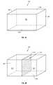
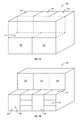
- FIGS. 2A-2Cdepict various implementations of a spatial framework 200 .
- the spatial framework 200can comprise a simple cube.
- the millwork software 100can comprise a plurality of simply shaped frameworks 200 that can be used as starting points for designing an architectural element.
- the spatial framework 200can be a computer model of an architectural element that captures the design intent of a user.
- the spatial framework 200can capture data relating to the outline of an architectural element and the position of components in the element with respect to each other.
- the spatial framework 200can comprise a space 250 that is associated with an independently executable software object.
- the independently executable software objectcan assist in tracking and managing the various components of the designed architectural element.
- the space 250 and independently executable software objectare both managed by the spaces module 144 .
- FIG. 2Aalso depicts that the framework 200 can comprise “facets” 202 , 204 , 206 and boundaries 208 .
- “facets” 202 , 204 , 206represent surfaces within the framework. Facets 202 , 204 , 206 , however, may not always correlate to surfaces within the finished architectural element. For example, facets 202 , 204 , 206 may only be quasi-two-dimensional because they can comprise a specified thickness. In some cases, a user can set the thickness of a particular facet to be zero. As a result the facet can still be a part of the framework 200 but it will not be a part of the finished architectural element. “Boundaries,” on the other hand, represent lines where facets meet. In at least one implementation, a specific boundary's location can be defined with respect to the other boundaries that the specific boundary intersects.
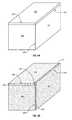
- FIG. 2Bdepicts an implementation of a framework 200 that has been bisected by a “cube splitter” 210 .
- the cube splitter 210splits or divides space 250 in half creating two new spaces 212 and 214 .
- the creation of two new spaces 212 , 214also results in the creation of two new independently executable software objects associated with each space 212 , 214 .
- cubes and squaresare used to illustrate embodiments of the present invention within this application, in at least one implementation, many different shapes and configurations of a framework 200 can be used.
- the newly created independently executable software objects associated with spaces 212 and 214may each inherit the parameters and characteristics of the independently executable software object that was originally associated with space 250 .
- space 250originally comprises a set of drawers
- spaces 212 and 214can each automatically comprise a set of drawers that mirror the original drawers of space 250 .
- the cube splitter 210can also create a new facet 216 within the framework 200 and a plurality of new facets (for example 220 , 222 ) on each external surface of the framework 200 .
- the new facets 216 , 220 , 222can each comprise a unique thicknesses such that the facets 216 , 220 , 222 comprises physical surfaces within the architectural element, or the facets 216 , 220 , 222 can comprise thicknesses of zero, resulting in the facets 216 , 220 , 222 only being represented within the framework 200 but not within the finished architectural element.
- FIG. 2Cdepicts the framework of FIG. 2B comprising two facet splitters 230 , 232 .
- the facet splitters 230 , 232can split facet 222 into three new facets 234 , 236 , 238 .
- a facet splitter 230 , 232can split only facets 220 , 222 , 234 , 236 , 238 , as opposed to a cube splitter 210 , which can split an entire space 250 , 212 , 214 .
- the new facets 234 , 236 , 238remain associated with space 214 and thus can be associated with the independently executable software object that is associated with space 214 .
- FIG. 3depicts a quasi-two-dimensional view of front face 204 of the framework 200 from FIG. 2C .
- the viewis quasi-two-dimensional because each facet can in fact comprise a thickness.
- FIG. 3shows facet 220 , which was formed by the placement of cube splitter 210 , and facets 234 , 236 , and 238 , which were formed by the placement of facet splitters 230 and 232 .
- FIG. 3depicts the end point 300 , 301 , 302 , 303 , 304 , 305 , 306 , 307 , 320 , 322 of each boundary within the front face of the framework.
- a usercan interact with the framework 200 through either a three-dimensional view (e.g., FIGS. 2A-2C ) or through a quasi-two-dimensional view (e.g., FIG. 3 ). In either view, the location and behavior of the facets can be managed by the facet module 142 .
- the location and positioning of the cube splitters 210 and facet splitters 230 , 236 , 238 within the frameworkcan be tracked with respect to the end points 300 , 301 , 302 , 303 , 304 , 305 , 306 , 307 , 320 , 322 of each respective facet splitter 230 , 236 , 238 or cube splitter 210 , and in particular, where those end points intersect other boundaries.
- the location of the end point intersectionscan be tracked as a finite distance or as a proportion of the total length of the respective boundary.
- facet splitter 230comprises end points 301 and 305 .
- the location of facet splitter 230can be designated as end point 301 being located distance 310 from the top of cube splitter 210 and end point 305 being located distance 312 from the top of side boundary 340 .
- the location of facet splitter 232can be designated as end point 302 being positioned 1 ⁇ 3 up the length of cube splitter 210 , and similarly, end point 306 being location 1 ⁇ 3 up the length of side boundary 340 .
- Facet splitter 232can change in absolute position such that each end point 302 , 306 is 1 ⁇ 3 up the length of their respective boundaries 210 , 340 .
- the framework 200can be shrunk so much that absolute distance 310 and distance 312 exceed 2 ⁇ 3 of the total length of boundaries 210 and 340 respectively.
- the framework module 140can automatically determine that either facet splitter 232 or facet splitter 230 should automatically be removed leaving only a single facet splitter 232 , 230 .
- a usercan set an option to automatically give fixed lengths 310 , 312 priority over proportional lengths 303 , 316 or to automatically give proportional lengths 303 , 316 priority over fixed lengths 310 , 312 .
- a usermay be able to set an option that gives priority to the first facet splitter 230 , 232 or cube splitter 210 created over subsequent facet splitters 230 , 232 or cube splitters 210 .
- a usermay be able to set an option that gives priority to the last facet splitter 230 , 232 or cube splitter 210 created over previous facet splitters 230 , 232 or cube splitters 210 .
- a usercan specifically designate that a particular facet splitter 230 , 23 or cube splitter 210 should be given priority over other facet splitters 230 , 232 and/or cube splitters 210 .
- Allowing a user to determine whether a facet splitter or cube splitter should be located on a proportional distance basis or on an absolute distance basiscan provide the user with significant control over how an architectural element can be resized and manipulated. Additionally, allowing a user to determine the priority that particular cube splitters and/or facet splitters can be given when the splitters conflict with each allows a user to have control over the final configuration of an architectural element that has been resized.
- FIGS. 4A and 4Bdepict various implementations of boundary detection and correction.
- the useras a user designs a framework 200 for a particular architectural element, the user is able to specify the type of joints that the user desires to join particular surfaces of the architectural element.
- the boundary module 146can analyze the framework to verify that no anomalies exists within the designated joints.
- FIG. 4Adepicts a simple architectural element that comprises a visible upper surface 400 , a visible side surface 404 , and a visible front surface 402 .
- the front surface 402 and the side surface 404meet each other at miter joint 420
- the side surface 404 and the upper surface 400meet each other at joint 430 where upper surface 400 overlaps side surface 404
- upper surface 400 and front surface 402meet each other at joint 410 where upper surface 400 overlaps front surface 402 .
- the boundary module 146can analyze the joints of FIG. 4A and determine that the above-recited joints do not create any anomalies, and can thus be left as they are.
- top surface 400meets front surface 402 at joint 412 where front panel 402 overlaps upper surface 400 .
- front surface 402meets side surface 404 at joint 422 where side surface 404 overlaps front surface 402 .
- side surface 404meets upper surface at joint 432 where upper surface 400 overlaps side surface 404 .
- the boundary module 146can analyze the joints of FIG. 4B and identify the presence of anomaly 440 . Additionally, in response to identifying the presence of anomaly 440 , the boundary module 146 can resolve the anomaly 440 by automatically adjusting the joints. For example, the boundary module 146 can change boundary 422 such that the front panel 402 overlaps the side panel 404 . One will appreciate that this change in the joint configuration will resolve the anomaly.
- the boundary module 146can operate such that the most recently specified joint is preserved and others are changed. In contrast, the boundary module 146 can change joints such that the earliest specified joints are preserved and the most recently specified joints are changed. In addition, in at least one implementation, a user can specify that a particular joint be given priority over other joints.
- the boundary module 146can allow a designer to make changes to the joints of a particular architectural element at any time without having to worry about anomalies. For example, if a designer has created a framework for a dresser, but a customer would prefer different joints, the designer can simply change the borders as requested and the boundary module 146 can automatically implement the change, verify that no anomalies exist, and if so, correct the anomaly.
- the manufacturing preparation module 130can prepare the framework 200 for actual production at a millwork facility.
- the manufacturing preparation module 130can adjust the framework 200 to meet the specification of the millwork facility and/or the end client. In at least one implementation, this can include adjusting the framework 200 to incorporate a specific material type, or a specific material thickness, adjusting the framework 200 to fit within a particular space, incorporating the appropriate third party hardware into the design, incorporating the appropriate attachments into the framework, or adjusting some other portion of the framework 200 .
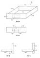
- FIG. 5Adepicts a portion of a framework 200 representing a drawer 500 .
- the depicted drawer 500comprises a backside 522 , a left side 532 , a right side 530 , a front side 520 , and a bottom 510 .
- the manufacturing preparation module 130can identify that a front side 520 comprises a third party hardware interface area 540 (i.e., a location where a handle can be attached).
- the manufacturing preparation module 130can access information relating the appropriate attachment.
- the building preferences and specifications of a variety of millwork facilitiesmay be stored within the storage device 150 .
- the manufacturing preparation module 130can determine the millwork facility that will be manufacturing the architectural element and can then access the stored information from the storage device 150 .
- the manufacturing preparation module 130can identify that the millwork facility utilizes handles that are anchored by two screws a certain distance apart. Based upon this information the manufacturing preparation module 130 can place two holes that are the appropriate distance apart within the third party hardware interface area 540 of the front side 520 as shown in FIG. 5B .
- the manufacturing preparation module 130can identify the type of connections that are appropriate for a particular framework 200 .
- the appropriate type of connectionmay be specific to the millwork facility that is manufacturing the architectural element, may be specified by an end client, or may be determined through some other means. Accordingly, prior to determining a connection type, panels are depicted as abutting with no particular connection 542 , as shown in FIG. 5C .
- the manufacturing preparation module 130can identify that a connection 542 is supposed to exist between the two surfaces 510 , 542 . Using information stored within the storage device 150 of from user input the manufacturing preparation module 130 can determine that appropriate type of connection.
- FIG. 5Ddepicts the drawer of FIG. 5C after the manufacturing preparation module 130 has applied a specified connection type 532 to the drawer.
- the connection 532can comprise the bottom side 510 being inset into the right side 530 .
- the manufacturing preparation module 130can create a file that will direct a millwork facility to cut a groove into the side wall of right side 530 at such a depth and location that the joint functions as designed in FIG. 5D .
- a millwork facilitycan prepare a parts list and design preference file and provide the list to the millwork software 100 .
- the manufacturing preparation module 130can automatically incorporate the parts and design preferences of the millwork facility into the framework 100 .
- the manufacturing preparation module 130can transform a framework consisting of planes, spaces, lines and other abstract features into a schematic that incorporates the proper measurements, materials, material widths, and third party hardware.
- the manufacturing preparation module 130can generate CNC code (or equivalent) that describes the architectural element.
- the manufacturing preparation module 130can generate parameters that are exported to a post processor that generates the CNC code. Once the appropriate CNC code is generated a millwork facility can use the code to create the designed architectural element.
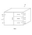
- FIG. 6depicts a finished rendering of the architectural element 200 .
- the storage unit 600comprises a cupboard 602 that correlates with space 212 that was create by the placement of cube splitter 210 .
- the door 610 of the cupboardcan be associated with facet 220 .
- the desk 600comprises three drawers 604 , 606 , 608 that were created by the combined placement of the cube splitter 210 and the facet splitters 230 and 232 .
- facet 234can be associated with drawer 604 , facet 236 with drawer 606 , and facet 238 with drawer 608 .
- additional designingthat was not depicted directly by this application may have also been added to the framework 200 .
- the drawer 500 of FIGS. 5A-5Dmay have also been designed and added to the framework 200 of FIG. 6 .
- gapscan be automatically added to the various components of a framework 200 such that features like drawers 234 , 236 , 238 and doors 610 are easy to open and close and are not overly snug.
- the gapsmay comprise slight millimeter spaces that are incorporated around the edges of a particular facet 212 , 234 , 236 , 238 .
- the storage devicecan contain visual information relating to various third party hardware that specific millwork facilities use.
- the user interface module 120can render a depiction of the architectural element, in this case the storage unit 600 , displaying the unit as it will appear in its final form, including the correct connection types and third party hardware.
- the usercan store the design within the storage device 150 for later access. For example, in at least one implementation, this allows the user to incorporate the architectural element into a new design.
- the designed frameworkcan be recursively linked to an independently executable software object within another framework.
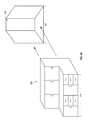
- FIGS. 7A and 7Bdepict implementations for incorporating one framework 200 into another.
- FIG. 7Adepicts a master framework 700 that includes a counter 710 , three upper spaces 702 , 704 , 706 , and two larger lower spaces 730 , 732 .
- the framework module 140can associate a distinct framework 200 with a space 730 , 732 .
- the space module 144can use the recursion module 148 to associate a distinct framework with the independently executable software object that is associated with the space 730 , 732 .
- the systemassociates each space 730 , 732 within a framework 700 with an independently-executable software object, which can recursively reference another distinct framework 200 .
- an independently executable software objectcomprises a set of computer-executable instructions used in object-oriented program code, and which relate to a particular physical component or feature.
- software objectscan be interrelated via parent/child dependency relationships where changes in a parent object flow through to a child object and vice versa.
- a software object created for a tablemay have several child objects for each leg.
- the software objectscan be related to other software objects that represent physically proximate components (e.g., a wall object that is positioned next to the table object).
- table software object and leg software objectscan independently execute in a correlated fashion to ensure each corresponding physical component (i.e., the table top, or the table legs) is positioned appropriately, or otherwise colored and designed consistent with the user's specifications.
- FIG. 7Bdepicts the resulting master framework 700 that includes spaces 702 , 704 , and 706 , which can be designed into cupboards, and spaces 730 and 732 , which both now contain frameworks 200 that are associated with storage units 600 .
- associating distinct frameworks 200 with spaces 730 , 732 within a master frameworkprovides a user with tremendous power and flexibility in creating a design.
- each framework 200can independently access a framework module 140 and all other associated modules 142 , 144 , 146 , 148 . This can allow a framework 200 to dynamically and automatically adjust to any changes that are made to a master framework 700 .
- a storage device 150can comprise a framework library of pre-designed architectural elements. Each of these stored frameworks can be associated with one or more independently executable software objects that can be recursively linked to other frameworks. For example, a designer can design an office space by accessing a group of stored frameworks that represent shelving units, desks, filing cabinets, cupboards, drawers, etc.
- a designercan simply insert the chosen framework into a space within a master framework.
- a designercan create a master framework that represents an entire office. Additionally, because the entire office was designed using spatial frameworks associated with independently executable software objects, the entire office design can change automatically to account for different sizes, materials, features, etc. and such changes will correctly propagate throughout the design.
- FIG. 8Adepicts the cabinet system 800 designed in FIGS. 7A and 7B .
- the cabinet system 800comprises a length 810
- a receiving wall 830comprises a length 820 .
- length 810is significantly longer than length 820 of the receiving wall.
- a usercan specify that the length of the cabinet system 800 should be length 820 , and the framework module 140 can automatically adjust the length of the cabinet system 800 to be length 820 , while at the same time automatically and correctly adjusting all of the features of the cabinet system.
- FIG. 8Bdepicts an implementation of an adjusted cabinet system 800 .
- the framework module 140automatically removed a cupboard and one of the storage units.
- the removal of the cupboard and storage unitmay be a result of using absolute measurements when tracking the location and behavior of the cube splitters 210 and facet splitters 230 , 232 as described with respect to FIG. 3 .
- the framework module 140may have identified that the storage unit length was reduced so much that there was no longer room to place the cube splitters 210 and facet splitters 230 , 232 as was specified. Accordingly, the framework module 140 can automatically determine that because the original length specifications cannot be met, a cupboard and a storage unit should be removed.
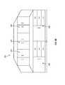
- FIGS. 9A and 9Bdepict an architectural element being expanded to fit a particular specification.
- the cabinet system 800comprises a length 810 and a receiving wall 930 comprises a length 910 .
- length 810is significantly smaller than length 910 of the receiving wall 930 .
- a usercan specify that the length of the cabinet system 800 should be 910 , and the framework module 140 can automatically adjust the length of the cabinet system 800 to be length 910 while at the same time automatically and correctly adjusting all of the features of the cabinet system.
- FIG. 9Bdepicts an implementation of an adjusted cabinet system 800 .
- the framework module 140automatically expanded the length of the storage units 600 and added double doors 940 to each of the three cabinets.
- the expansion of the storage unitmay be a result of using proportional measurements when tracking the location and behavior of the cube splitters 210 and facet splitters 230 , 232 as described with respect to FIG. 3 .
- the framework module 140may have identified that the cube splitter between spaces 730 and 732 was specified as being placed at half the length of the bottom most boundary. As such, the framework module 140 simply expanded the storage units to fill the larger length.
- the framework module 140 and/or the manufacturing preparation module 130can automatically identify some finishing features, such as, for example, whether a cupboard is narrow enough to only require a single door, or so wide as to require double doors 940 .
- the framework module 140 and/or the manufacturing preparation module 130determined that double door were appropriate due to the increased length of the cabinet system 800 .
- FIGS. 1-9 and the corresponding textillustrate or otherwise describe one or more components, modules, and/or mechanisms for creating a variable spatial framework for use in designing and manufacturing an architectural component.
- implementations of the present inventioncan also be described in terms of methods comprising one or more acts for accomplishing a particular result.
- FIGS. 10 and 11 and the corresponding textillustrate flowcharts of a sequence of acts in a method for creating a variable spatial framework for use in designing and manufacturing an architectural component. The acts of FIGS. 10 and 11 are described below with reference to the components and modules illustrated in FIGS. 1-9 .
- FIG. 10illustrates that a method for creating a variable spatial framework for use in designing and manufacturing an architectural component can comprise an act 1010 of receiving inputs for spatial framework.
- Act 1010includes receiving input for a spatial framework for use in designing and manufacturing an architectural component.
- the spatial frameworkcan define a three-dimensional space having a plurality of boundaries.
- FIGS. 1 and 2A-2Cshow various implementations of a millwork software application 100 receiving inputs regarding a spatial framework that defines a three-dimensional space having a plurality of boundaries.
- FIG. 10also shows that the method can comprise an act 1020 of receiving inputs to divide a space.
- Act 1020includes receiving input to divide the three-dimensional space, the three-dimensional space dividing input changing the three-dimensional space into multiple independent cells.
- FIG. 2A-2Cshow that a framework can be divided into multiple cells.
- FIG. 10shows that the method can comprise an element 1030 wherein each cell comprises a software object.
- Element 1030can include each independent cell comprising an independently executable software object.
- FIG. 1 and FIGS. 7A and 7Balong with the accompanying description, describe the interaction and use of the independently executable software object that can be associated with spaces within the framework.
- FIG. 10shows that the method can comprise an element 1040 wherein boundaries automatically adjust.
- Element 1040can include a plurality of boundaries of the spatial framework that can be automatically adjusted upon receiving an input defining a manufacturing constraint.
- FIGS. 8A-9Bshow various implementations of a framework automatically adjusting to meet particular specifications.
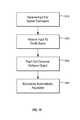
- FIG. 11shows that a method for creating a variable spatial framework for use in designing and manufacturing an architectural component can comprise an act 1110 of receiving inputs for spatial framework.
- Act 1110includes receiving input for a spatial framework for use in designing and manufacturing an architectural component, the spatial framework defining a three-dimensional space having a plurality of boundaries.
- FIGS. 1 and 2A-2Cshow various implementations of a millwork software application 100 receiving inputs regarding a spatial framework that defines a three-dimensional space having a plurality of boundaries.
- FIG. 11also shows that the method can comprise an act 1120 of receiving inputs to divide a space.
- Act 1120includes receiving input to divide the three-dimensional space, the three-dimensional space dividing input changing the three-dimensional space into multiple independent cells, wherein each independent cell comprises an independently executable software object.
- FIG. 2A-2Cshow that a framework can be divided into multiple cells
- FIG. 1 and FIGS. 7A and 7Balong with the accompanying description, describe the interaction and use of the independently executable software object that can be associated with spaces within the framework.
- FIG. 11shows that the method can comprise an act 1130 of receiving a manufacturing constraint.
- Act 1130includes receiving at least one manufacturing constraint that defines at least one physical characteristic of an object that will be manufactured based upon the spatial framework.
- FIGS. 8A-9Bshow various implementations of a framework automatically adjusting to meet manufacturing constraints relating to the final length of the object that will be manufactured.
- FIG. 11shows that the method can comprise an act 1140 of automatically accessing a software object.
- Act 1140includes automatically accessing at least one independently executable software object to adjust at least a portion of the spatial framework to incorporate the received manufacturing constraint.
- FIG. 1 and FIGS. 7A and 7Balong with the accompanying description, describe the interaction and use of the independently executable software object that can be associated with spaces within the framework.
- FIGS. 1-11provide a number of components, schematics, and mechanisms for creating a variable spatial framework for use in designing and manufacturing an architectural component. Additionally, one or more implementations can allow a user to develop an architectural element, such as a desk or even an entire kitchen, without knowing the final constraints of the design. For example, a user can design a kitchen, including cabinets, drawers, counter tops, sink locations, etc., without knowing the final size of the kitchen, the materials that will be used to construct the cabinet and counter, or the final third party elements, such as the actual sink type, knob and handle configurations, wood joints, etc.
- implementations of the present inventionprovide tremendous flexibility and power to designers and millwork facilities by allowing designers to construct detailed and specific schematics that can automatically be adjusted to the meet the needs of a user and the manufacturing process of a millwork facility.
- the embodiments of the present inventionmay comprise a special purpose or general-purpose computer including various computer hardware components, as discussed in greater detail below.
- Embodiments within the scope of the present inventionalso include computer-readable media for carrying or having computer-executable instructions or data structures stored thereon.
- Such computer-readable mediacan be any available media that can be accessed by a general purpose or special purpose computer.
- such computer-readable mediacan comprise RAM, ROM, EEPROM, CD-ROM or other optical disk storage, magnetic disk storage or other magnetic storage devices, or any other medium which can be used to carry or store desired program code means in the form of computer-executable instructions or data structures and which can be accessed by a general purpose or special purpose computer.
- a network or another communications connectioneither hardwired, wireless, or a combination of hardwired or wireless
- the computerproperly views the connection as a computer-readable medium.
- any such connectionis properly termed a computer-readable medium.
- Computer-executable instructionscomprise, for example, instructions and data which cause a general purpose computer, special purpose computer, or special purpose processing device to perform a certain function or group of functions.
- the flexible diescan include flexible protrusions on both the front and back surfaces.
- a single flexible diecan form recesses into surfaces of two different panels at the same time.
- the panelscan include recesses in both the front and back surfaces.
Landscapes
- Engineering & Computer Science (AREA)
- Physics & Mathematics (AREA)
- General Physics & Mathematics (AREA)
- Geometry (AREA)
- Theoretical Computer Science (AREA)
- Computer Hardware Design (AREA)
- Human Computer Interaction (AREA)
- Manufacturing & Machinery (AREA)
- Automation & Control Theory (AREA)
- Mathematical Optimization (AREA)
- Computational Mathematics (AREA)
- Pure & Applied Mathematics (AREA)
- Evolutionary Computation (AREA)
- General Engineering & Computer Science (AREA)
- Civil Engineering (AREA)
- Architecture (AREA)
- Mathematical Analysis (AREA)
- Structural Engineering (AREA)
- Management, Administration, Business Operations System, And Electronic Commerce (AREA)
- Stored Programmes (AREA)
Abstract
Description
Claims (20)
Applications Claiming Priority (1)
| Application Number | Priority Date | Filing Date | Title |
|---|---|---|---|
| PCT/US2013/043735WO2014193415A1 (en) | 2013-05-31 | 2013-05-31 | Associating computer-executable objects with three-dimensional spaces within an architectural design environment |
Publications (2)
| Publication Number | Publication Date |
|---|---|
| US20160070255A1 US20160070255A1 (en) | 2016-03-10 |
| US9958858B2true US9958858B2 (en) | 2018-05-01 |
Family
ID=51989266
Family Applications (2)
| Application Number | Title | Priority Date | Filing Date |
|---|---|---|---|
| US14/115,299ActiveUS9958858B2 (en) | 2013-05-31 | 2013-05-31 | Associating computer-executable objects with three-dimensional spaces within an architectural design environment |
| US14/891,007Active2034-06-03US10289758B2 (en) | 2013-05-31 | 2014-03-24 | Automatically resolving boundaries within an architectural design environment |
Family Applications After (1)
| Application Number | Title | Priority Date | Filing Date |
|---|---|---|---|
| US14/891,007Active2034-06-03US10289758B2 (en) | 2013-05-31 | 2014-03-24 | Automatically resolving boundaries within an architectural design environment |
Country Status (5)
| Country | Link |
|---|---|
| US (2) | US9958858B2 (en) |
| EP (3) | EP2956873A4 (en) |
| CA (3) | CA2883079C (en) |
| SG (3) | SG11201605983TA (en) |
| WO (2) | WO2014193415A1 (en) |
Cited By (1)
| Publication number | Priority date | Publication date | Assignee | Title |
|---|---|---|---|---|
| CN111247080A (en)* | 2017-10-04 | 2020-06-05 | 蒂森克虏伯座椅电梯有限公司 | Methods for planning platform lifts |
Families Citing this family (11)
| Publication number | Priority date | Publication date | Assignee | Title |
|---|---|---|---|---|
| US20160004247A1 (en)* | 2014-07-03 | 2016-01-07 | Thermwood Corporation | System for producing components of various product designs |
| US9836782B2 (en)* | 2015-03-27 | 2017-12-05 | Domans, Inc. | System and method for designing, receiving order of, and placing production-order of custom-made furniture and program therefor |
| US10197990B2 (en)* | 2015-08-01 | 2019-02-05 | Michael Weinig, Inc. | System for optimizing the execution of parametric joinery for solid wood products |
| US10404938B1 (en) | 2015-12-22 | 2019-09-03 | Steelcase Inc. | Virtual world method and system for affecting mind state |
| US10181218B1 (en) | 2016-02-17 | 2019-01-15 | Steelcase Inc. | Virtual affordance sales tool |
| US11480943B2 (en) | 2016-11-08 | 2022-10-25 | Aectual Holding B.V. | Method and assembly for forming a building element |
| WO2018088898A1 (en) | 2016-11-08 | 2018-05-17 | Aectual Holding B.V. | Method and assembly for forming a building element |
| US10182210B1 (en) | 2016-12-15 | 2019-01-15 | Steelcase Inc. | Systems and methods for implementing augmented reality and/or virtual reality |
| US11372390B2 (en)* | 2017-07-28 | 2022-06-28 | Domans, Inc. | System, method, and program for manufacturing computer-designed part members of furniture using machining equipment |
| JP7617749B2 (en)* | 2020-01-21 | 2025-01-20 | 株式会社電通 | Furniture Design System |
| CN112784339B (en)* | 2021-01-22 | 2024-03-29 | 深圳国研建筑科技有限公司 | BIM-based assembled shelter hospital design method, system, intelligent terminal and storage medium |
Citations (95)
| Publication number | Priority date | Publication date | Assignee | Title |
|---|---|---|---|---|
| US3972163A (en) | 1974-10-11 | 1976-08-03 | Coperthwaite William S | Concentric building |
| US4207714A (en) | 1978-12-22 | 1980-06-17 | Mehls William L | Building construction |
| US4705401A (en) | 1985-08-12 | 1987-11-10 | Cyberware Laboratory Inc. | Rapid three-dimensional surface digitizer |
| JPH0239377A (en) | 1988-07-29 | 1990-02-08 | Nippon Sheet Glass Co Ltd | Simulating method for see-through distortion of plate glass |
| US5255207A (en) | 1988-06-16 | 1993-10-19 | Larry Cornwell | Method for designing and detailing cabinets |
| US5625827A (en) | 1993-09-21 | 1997-04-29 | Gary M. Krause | Method and system of blueprint document manipulation |
| US5673374A (en) | 1992-04-28 | 1997-09-30 | Hitachi, Ltd. | Method and apparatus for non-disturbed specular reflections on textured surfaces |
| US5801958A (en) | 1990-04-06 | 1998-09-01 | Lsi Logic Corporation | Method and system for creating and validating low level description of electronic design from higher level, behavior-oriented description, including interactive system for hierarchical display of control and dataflow information |
| US5866419A (en) | 1996-09-16 | 1999-02-02 | Meder; Martin G. | Roller bottle |
| US5870771A (en) | 1996-11-15 | 1999-02-09 | Oberg; Larry B. | Computerized system for selecting, adjusting, and previewing framing product combinations for artwork and other items to be framed |
| JP2000132706A (en) | 1998-10-27 | 2000-05-12 | Sony Computer Entertainment Inc | Recording medium, image processor and image processing method |
| US6078332A (en) | 1997-01-28 | 2000-06-20 | Silicon Graphics, Inc. | Real-time lighting method using 3D texture mapping |
| US6097394A (en) | 1997-04-28 | 2000-08-01 | Board Of Trustees, Leland Stanford, Jr. University | Method and system for light field rendering |
| US6268863B1 (en) | 1997-10-02 | 2001-07-31 | National Research Council Canada | Method of simulating a photographic camera |
| US6292810B1 (en) | 1997-03-03 | 2001-09-18 | Richard Steele Richards | Polymorphic enhanced modeling |
| WO2002059545A1 (en) | 2001-01-26 | 2002-08-01 | Genex Technologies, Inc. | Three-dimensional surface profile imaging method and apparatus using single spectral light condition |
| US6493679B1 (en) | 1999-05-26 | 2002-12-10 | Wireless Valley Communications, Inc. | Method and system for managing a real time bill of materials |
| US20030011596A1 (en) | 2001-06-03 | 2003-01-16 | Zhengyou Zhang | View-dependent image synthesis |
| US6580426B1 (en) | 1999-03-03 | 2003-06-17 | Canon Kabushiki Kaisha | Computer graphics apparatus for processing of data defining a three-dimensional computer model to partition the three-dimensional space into a plurality of sectors |
| US6629065B1 (en) | 1998-09-30 | 2003-09-30 | Wisconsin Alumni Research Foundation | Methods and apparata for rapid computer-aided design of objects in virtual reality and other environments |
| US20040027371A1 (en) | 2001-02-15 | 2004-02-12 | Denny Jaeger | Metro for creating and using linear time line and play rectangle |
| US20040075655A1 (en) | 1999-02-04 | 2004-04-22 | Canon Kabushiki Kaisha | 3D computer graphics processing apparatus and method |
| US20040100465A1 (en) | 2000-08-24 | 2004-05-27 | Stowe Jason A | Computerized image system |
| US20040174358A1 (en) | 2000-09-18 | 2004-09-09 | Hitachi, Ltd. | Method and apparatus for describing solid shapes, and CAD/CAM system which employs the method |
| US20050044133A1 (en) | 2001-07-27 | 2005-02-24 | Shinichiro Hashimoto | Information processing system for manufacturing building material, building material manufacturing method and facility, and building information circulating system |
| US20050072059A1 (en) | 2003-09-20 | 2005-04-07 | Hodsdon Edwin R. | Method and adjustable apparatus for masonry wall bracing |
| US20050104883A1 (en) | 2003-08-15 | 2005-05-19 | Microsoft Corporation | Precomputed radiance transfer for rendering objects |
| US6900841B1 (en) | 1999-01-11 | 2005-05-31 | Olympus Optical Co., Ltd. | Image processing system capable of applying good texture such as blur |
| US6971063B1 (en) | 2000-07-28 | 2005-11-29 | Wireless Valley Communications Inc. | System, method, and apparatus for portable design, deployment, test, and optimization of a communication network |
| US20060041842A1 (en) | 2004-08-17 | 2006-02-23 | Loberg Barrie A | Capturing a user's intent in design software |
| US7019753B2 (en) | 2000-12-18 | 2006-03-28 | Wireless Valley Communications, Inc. | Textual and graphical demarcation of location from an environmental database, and interpretation of measurements including descriptive metrics and qualitative values |
| US7062454B1 (en) | 1999-05-06 | 2006-06-13 | Jarbridge, Inc. | Previewing system and method |
| US7085697B1 (en) | 2000-08-04 | 2006-08-01 | Motorola, Inc. | Method and system for designing or deploying a communications network which considers component attributes |
| US7096173B1 (en) | 2000-08-04 | 2006-08-22 | Motorola, Inc. | Method and system for designing or deploying a communications network which allows simultaneous selection of multiple components |
| US7099803B1 (en) | 2000-09-06 | 2006-08-29 | Proficiency Solutions Ltd. | Data exchange between computer aided design systems |
| US20060274064A1 (en) | 2005-06-01 | 2006-12-07 | Microsoft Corporation | System for softening images in screen space |
| US7155228B2 (en) | 1999-05-26 | 2006-12-26 | Wireless Valley Communications, Inc. | Method and system for analysis, design, and optimization of communication networks |
| US7171208B2 (en) | 2000-08-04 | 2007-01-30 | Motorola, Inc. | Method and system, with component kits for designing or deploying a communications network which considers frequency dependent effects |
| US20070098290A1 (en) | 2005-10-28 | 2007-05-03 | Aepx Animation, Inc. | Automatic compositing of 3D objects in a still frame or series of frames |
| US7216092B1 (en) | 2000-04-14 | 2007-05-08 | Deluxe Corporation | Intelligent personalization system and method |
| US20070109310A1 (en) | 2005-11-01 | 2007-05-17 | Microsoft Corporation | Sketching Reality |
| US7243054B2 (en) | 1999-07-14 | 2007-07-10 | Wireless Valley Communications, Inc. | Method and system for displaying network performance, cost, maintenance, and infrastructure wiring diagram |
| US7246045B1 (en) | 2000-08-04 | 2007-07-17 | Wireless Valley Communication, Inc. | System and method for efficiently visualizing and comparing communication network system performance |
| US7277830B2 (en) | 2004-08-17 | 2007-10-02 | Dirtt Environmental Solutions Ltd. | Capturing a user's design intent with resolvable objects |
| JP2007264707A (en) | 2006-03-27 | 2007-10-11 | Samii Kk | Image generation device, game machine, and image generation program |
| US7299168B2 (en) | 1999-07-14 | 2007-11-20 | Wireless Valley Communications, Inc. | System for the three-dimensional display of wireless communication system performance |
| US20070276791A1 (en) | 2006-05-26 | 2007-11-29 | Anthony Peter Fejes | System and method for modeling interactions |
| WO2007138560A2 (en) | 2006-05-31 | 2007-12-06 | Andries Hendrik Potgieter | Design facilitation |
| US20090128558A1 (en) | 2007-11-16 | 2009-05-21 | M.I.C. Industries, Inc. | Systems and methods for computational design and modeling of buildings |
| US20090187389A1 (en) | 2008-01-18 | 2009-07-23 | Lockheed Martin Corporation | Immersive Collaborative Environment Using Motion Capture, Head Mounted Display, and Cave |
| WO2009111885A1 (en) | 2008-03-11 | 2009-09-17 | Dirtt Environmental Solutions, Ltd. | Automatically creating and modifying furniture layouts in design software |
| US7623137B1 (en) | 2006-02-15 | 2009-11-24 | Adobe Systems, Incorporated | Successive-convolution-compositing technique for rendering translucent surfaces |
| KR20090126574A (en) | 2008-06-04 | 2009-12-09 | 조정구 | Design system of wooden conditional building of post and beam structure by combination method of basic building unit and design method using same |
| US20100018141A1 (en) | 2006-01-31 | 2010-01-28 | Kelly Kevin P | Modular wall system |
| US20100036520A1 (en) | 2008-08-07 | 2010-02-11 | Barbir Wesley V | Method of carving three-dimensional artwork |
| US20100128038A1 (en) | 2008-11-25 | 2010-05-27 | Sony Computer Entertainment America Inc. | Method and apparatus for interpolating color and direction as one entity in computer graphics |
| EP2207140A2 (en) | 2009-01-12 | 2010-07-14 | Navteq North America, LLC | Transit view for a traffic report |
| US7817823B1 (en) | 2007-04-27 | 2010-10-19 | Adobe Systems Incorporated | Calculating shadow from area light sources using a spatially varying blur radius |
| US20100268513A1 (en) | 2006-02-16 | 2010-10-21 | Dirtt Environmental Solutions Ltd. | Rendering and modifying cad design entities in object-oriented applications |
| US7825937B1 (en) | 2006-06-16 | 2010-11-02 | Nvidia Corporation | Multi-pass cylindrical cube map blur |
| US20110054652A1 (en) | 2009-08-27 | 2011-03-03 | Heil Duane A | Building Construction Software and System |
| US20110191706A1 (en) | 2004-08-17 | 2011-08-04 | Dirtt Environmental Solutions Ltd. | Automatically creating and modifying furniture layouts in design software |
| US20110227922A1 (en) | 2010-03-22 | 2011-09-22 | Samsung Electronics Co., Ltd. | Apparatus and method extracting light and texture, and rendering apparatus using light and texture |
| US20110227924A1 (en) | 2010-03-17 | 2011-09-22 | Casio Computer Co., Ltd. | 3d modeling apparatus, 3d modeling method, and computer readable medium |
| US20110265405A1 (en) | 2010-04-29 | 2011-11-03 | Nick Ksenych | Modular Secondary Containment System |
| US8150660B2 (en) | 2007-05-01 | 2012-04-03 | M.E.P. Cad, Inc. | Methods and apparatuses for automatically selecting a pipe in a CAD drawing |
| US8255338B1 (en) | 2006-01-10 | 2012-08-28 | Brittan Jeffrey C | Method for designing and estimating costs of food service equipment |
| US8271336B2 (en) | 1999-11-22 | 2012-09-18 | Accenture Global Services Gmbh | Increased visibility during order management in a network-based supply chain environment |
| US8276008B2 (en) | 2008-04-21 | 2012-09-25 | Adaptive Computing Enterprises, Inc. | System and method for managing energy consumption in a compute environment |
| US8285707B2 (en) | 2006-11-08 | 2012-10-09 | International Business Machines Corporation | Method of querying relational database management systems |
| US8290849B2 (en) | 2002-04-30 | 2012-10-16 | Analect Benefit Finance, Llc | Method and system for administering the hedging of an employee deferred compensation plan using swaps |
| US8301527B2 (en) | 2001-02-09 | 2012-10-30 | Tarbox Brian C | Systems and methods for improving investment performance |
| US20120288184A1 (en) | 2010-01-14 | 2012-11-15 | Humaneyes Technologies Ltd. | Method and system for adjusting depth values of objects in a three dimensional (3d) display |
| WO2012162442A2 (en) | 2011-05-23 | 2012-11-29 | Blu Homes, Inc. | Method, apparatus and system for customizing a building via a virtual environment |
| US8332401B2 (en) | 2004-10-01 | 2012-12-11 | Ricoh Co., Ltd | Method and system for position-based image matching in a mixed media environment |
| US8332827B2 (en) | 2006-12-01 | 2012-12-11 | Murex S.A.S. | Produce graph oriented programming framework with scenario support |
| US8335789B2 (en) | 2004-10-01 | 2012-12-18 | Ricoh Co., Ltd. | Method and system for document fingerprint matching in a mixed media environment |
| WO2012173741A2 (en) | 2011-06-11 | 2012-12-20 | Dirtt Environmental Solutions Inc. | Automated re-use of structural components |
| US8386918B2 (en) | 2007-12-06 | 2013-02-26 | International Business Machines Corporation | Rendering of real world objects and interactions into a virtual universe |
| USRE44054E1 (en) | 2000-12-08 | 2013-03-05 | Ganz | Graphic chatting with organizational avatars |
| US8402473B1 (en) | 2006-09-28 | 2013-03-19 | Sap Ag | Managing consistent interfaces for demand business objects across heterogeneous systems |
| WO2013040016A1 (en) | 2011-09-12 | 2013-03-21 | Modsolar, Llc | System and method for optimized automated layout of solar panels |
| US8411086B2 (en) | 2009-02-24 | 2013-04-02 | Fuji Xerox Co., Ltd. | Model creation using visual markup languages |
| US8423391B2 (en) | 2005-07-28 | 2013-04-16 | Sap Ag | Systems and methods for automated parallelization of transport load builder |
| US8442850B2 (en) | 2006-03-30 | 2013-05-14 | Sap Ag | Providing accounting software application as enterprise services |
| US8510382B2 (en) | 2007-10-15 | 2013-08-13 | Insidesales.com | Apparatus system and method for responding to web form inquiries |
| US8521737B2 (en) | 2004-10-01 | 2013-08-27 | Ricoh Co., Ltd. | Method and system for multi-tier image matching in a mixed media environment |
| US8566419B2 (en) | 2007-12-12 | 2013-10-22 | Insidesales.com | Systems and methods for enhanced user communications |
| US8600989B2 (en) | 2004-10-01 | 2013-12-03 | Ricoh Co., Ltd. | Method and system for image matching in a mixed media environment |
| US8626877B2 (en) | 2000-05-22 | 2014-01-07 | Verizon Business Global Llc | Method and system for implementing a global information bus in a global ecosystem of interrelated services |
| US8645973B2 (en) | 2006-09-22 | 2014-02-04 | Oracle International Corporation | Mobile applications |
| US8650179B2 (en) | 2005-08-18 | 2014-02-11 | International Business Machines Corporation | Generating statistics for temporary tables during query optimization |
| US20140176530A1 (en) | 2012-12-21 | 2014-06-26 | Dassault Systèmes Delmia Corp. | Location correction of virtual objects |
| US8773433B1 (en) | 2006-04-12 | 2014-07-08 | Pixar | Component-based lighting |
| WO2014191828A1 (en) | 2013-05-31 | 2014-12-04 | Dirtt Environmental Solutions Inc. | Automatically resolving boundaries within an architectural design environment |
Family Cites Families (13)
| Publication number | Priority date | Publication date | Assignee | Title |
|---|---|---|---|---|
| US4964060A (en) | 1985-12-04 | 1990-10-16 | Hartsog Charles H | Computer aided building plan review system and process |
| NZ332446A (en) | 1998-10-21 | 2001-05-25 | Scottsdale Building Systems Lt | Method for forming structural members aided by a computer with connection features for assembly as elements of building frame |
| NL1008767C2 (en) | 1998-03-31 | 1999-10-01 | Regiplan B V | Simulation device for simulating images of at least one building. |
| CN1326080C (en) | 1999-08-03 | 2007-07-11 | 二宫健一 | Furniture design support system, design support method and medium storing design support program |
| US20050071135A1 (en)* | 2003-09-30 | 2005-03-31 | Vredenburgh David W. | Knowledge management system for computer-aided design modeling |
| WO2005114495A1 (en) | 2004-05-20 | 2005-12-01 | Chi Kuen Wong | A system and method of a scalable and rule-based building chassis platform for planning, developing and implementing product family architecture solutions in multi-storey buildings |
| US7292908B2 (en) | 2004-10-13 | 2007-11-06 | Robotic Built Structures, Inc. | Systems and methods for manufacturing customized prefabricated buildings including arbitrarily modularizing a building specification without using any pre-defined modules |
| US20080249756A1 (en) | 2007-04-06 | 2008-10-09 | Pongsak Chaisuparasmikul | Method and system for integrating computer aided design and energy simulation |
| US20090145075A1 (en) | 2007-12-08 | 2009-06-11 | Colin Michael Oakley | Timber-framed building structures, and method of constructing same |
| EP2189918A1 (en) | 2008-11-07 | 2010-05-26 | Dassault Systèmes | Computer-implemented method of computing, in a computer aided design system, of a boundary of a modeled object. |
| FR2965380B1 (en) | 2010-09-28 | 2013-04-26 | C4Ci Ltd | SYSTEM FOR DESIGNING A STRUCTURE OR A BUILDING |
| KR101833581B1 (en) | 2011-03-17 | 2018-02-28 | 아디타즈, 인크. | System and method for realizing a building system |
| CN102902848B (en) | 2012-09-18 | 2015-04-22 | 大连理工大学 | 3D Visual Simulation Method for Boundary Element Analysis |
- 2013
- 2013-05-31USUS14/115,299patent/US9958858B2/enactiveActive
- 2013-05-31EPEP13885841.0Apatent/EP2956873A4/ennot_activeWithdrawn
- 2013-05-31SGSG11201605983TApatent/SG11201605983TA/enunknown
- 2013-05-31WOPCT/US2013/043735patent/WO2014193415A1/enactiveApplication Filing
- 2013-05-31CACA2883079Apatent/CA2883079C/enactiveActive
- 2013-07-16WOPCT/US2013/050764patent/WO2014193426A1/enactiveApplication Filing
- 2013-07-16EPEP13885779.2Apatent/EP3005180A4/ennot_activeCeased
- 2013-07-16CACA2895313Apatent/CA2895313C/enactiveActive
- 2013-07-16SGSG11201605818VApatent/SG11201605818VA/enunknown
- 2014
- 2014-03-24USUS14/891,007patent/US10289758B2/enactiveActive
- 2014-03-24CACA2908924Apatent/CA2908924C/enactiveActive
- 2014-03-24SGSG11201606050XApatent/SG11201606050XA/enunknown
- 2014-03-24EPEP14804947.1Apatent/EP3005185A4/ennot_activeCeased
Patent Citations (98)
| Publication number | Priority date | Publication date | Assignee | Title |
|---|---|---|---|---|
| US3972163A (en) | 1974-10-11 | 1976-08-03 | Coperthwaite William S | Concentric building |
| US4207714A (en) | 1978-12-22 | 1980-06-17 | Mehls William L | Building construction |
| US4705401A (en) | 1985-08-12 | 1987-11-10 | Cyberware Laboratory Inc. | Rapid three-dimensional surface digitizer |
| US5255207C1 (en) | 1988-06-16 | 2001-01-09 | Larry Cornwell | Method for designing and detailing cabinets |
| US5255207A (en) | 1988-06-16 | 1993-10-19 | Larry Cornwell | Method for designing and detailing cabinets |
| JPH0239377A (en) | 1988-07-29 | 1990-02-08 | Nippon Sheet Glass Co Ltd | Simulating method for see-through distortion of plate glass |
| US5801958A (en) | 1990-04-06 | 1998-09-01 | Lsi Logic Corporation | Method and system for creating and validating low level description of electronic design from higher level, behavior-oriented description, including interactive system for hierarchical display of control and dataflow information |
| US5673374A (en) | 1992-04-28 | 1997-09-30 | Hitachi, Ltd. | Method and apparatus for non-disturbed specular reflections on textured surfaces |
| US5625827A (en) | 1993-09-21 | 1997-04-29 | Gary M. Krause | Method and system of blueprint document manipulation |
| US5866419A (en) | 1996-09-16 | 1999-02-02 | Meder; Martin G. | Roller bottle |
| US5870771A (en) | 1996-11-15 | 1999-02-09 | Oberg; Larry B. | Computerized system for selecting, adjusting, and previewing framing product combinations for artwork and other items to be framed |
| US6078332A (en) | 1997-01-28 | 2000-06-20 | Silicon Graphics, Inc. | Real-time lighting method using 3D texture mapping |
| US6292810B1 (en) | 1997-03-03 | 2001-09-18 | Richard Steele Richards | Polymorphic enhanced modeling |
| US6097394A (en) | 1997-04-28 | 2000-08-01 | Board Of Trustees, Leland Stanford, Jr. University | Method and system for light field rendering |
| US6268863B1 (en) | 1997-10-02 | 2001-07-31 | National Research Council Canada | Method of simulating a photographic camera |
| US6629065B1 (en) | 1998-09-30 | 2003-09-30 | Wisconsin Alumni Research Foundation | Methods and apparata for rapid computer-aided design of objects in virtual reality and other environments |
| JP2000132706A (en) | 1998-10-27 | 2000-05-12 | Sony Computer Entertainment Inc | Recording medium, image processor and image processing method |
| US6900841B1 (en) | 1999-01-11 | 2005-05-31 | Olympus Optical Co., Ltd. | Image processing system capable of applying good texture such as blur |
| US20040075655A1 (en) | 1999-02-04 | 2004-04-22 | Canon Kabushiki Kaisha | 3D computer graphics processing apparatus and method |
| US6580426B1 (en) | 1999-03-03 | 2003-06-17 | Canon Kabushiki Kaisha | Computer graphics apparatus for processing of data defining a three-dimensional computer model to partition the three-dimensional space into a plurality of sectors |
| US7062454B1 (en) | 1999-05-06 | 2006-06-13 | Jarbridge, Inc. | Previewing system and method |
| US7155228B2 (en) | 1999-05-26 | 2006-12-26 | Wireless Valley Communications, Inc. | Method and system for analysis, design, and optimization of communication networks |
| US6493679B1 (en) | 1999-05-26 | 2002-12-10 | Wireless Valley Communications, Inc. | Method and system for managing a real time bill of materials |
| US7299168B2 (en) | 1999-07-14 | 2007-11-20 | Wireless Valley Communications, Inc. | System for the three-dimensional display of wireless communication system performance |
| US7243054B2 (en) | 1999-07-14 | 2007-07-10 | Wireless Valley Communications, Inc. | Method and system for displaying network performance, cost, maintenance, and infrastructure wiring diagram |
| US8271336B2 (en) | 1999-11-22 | 2012-09-18 | Accenture Global Services Gmbh | Increased visibility during order management in a network-based supply chain environment |
| US7216092B1 (en) | 2000-04-14 | 2007-05-08 | Deluxe Corporation | Intelligent personalization system and method |
| US8626877B2 (en) | 2000-05-22 | 2014-01-07 | Verizon Business Global Llc | Method and system for implementing a global information bus in a global ecosystem of interrelated services |
| US6971063B1 (en) | 2000-07-28 | 2005-11-29 | Wireless Valley Communications Inc. | System, method, and apparatus for portable design, deployment, test, and optimization of a communication network |
| US7171208B2 (en) | 2000-08-04 | 2007-01-30 | Motorola, Inc. | Method and system, with component kits for designing or deploying a communications network which considers frequency dependent effects |
| US7096173B1 (en) | 2000-08-04 | 2006-08-22 | Motorola, Inc. | Method and system for designing or deploying a communications network which allows simultaneous selection of multiple components |
| US7085697B1 (en) | 2000-08-04 | 2006-08-01 | Motorola, Inc. | Method and system for designing or deploying a communications network which considers component attributes |
| US7246045B1 (en) | 2000-08-04 | 2007-07-17 | Wireless Valley Communication, Inc. | System and method for efficiently visualizing and comparing communication network system performance |
| US20040100465A1 (en) | 2000-08-24 | 2004-05-27 | Stowe Jason A | Computerized image system |
| US7099803B1 (en) | 2000-09-06 | 2006-08-29 | Proficiency Solutions Ltd. | Data exchange between computer aided design systems |
| US20040174358A1 (en) | 2000-09-18 | 2004-09-09 | Hitachi, Ltd. | Method and apparatus for describing solid shapes, and CAD/CAM system which employs the method |
| USRE44054E1 (en) | 2000-12-08 | 2013-03-05 | Ganz | Graphic chatting with organizational avatars |
| US7019753B2 (en) | 2000-12-18 | 2006-03-28 | Wireless Valley Communications, Inc. | Textual and graphical demarcation of location from an environmental database, and interpretation of measurements including descriptive metrics and qualitative values |
| WO2002059545A1 (en) | 2001-01-26 | 2002-08-01 | Genex Technologies, Inc. | Three-dimensional surface profile imaging method and apparatus using single spectral light condition |
| US8301527B2 (en) | 2001-02-09 | 2012-10-30 | Tarbox Brian C | Systems and methods for improving investment performance |
| US7299416B2 (en) | 2001-02-15 | 2007-11-20 | Denny Jaeger | Metro for creating and using linear time line and play rectangle |
| US20040027371A1 (en) | 2001-02-15 | 2004-02-12 | Denny Jaeger | Metro for creating and using linear time line and play rectangle |
| US20030011596A1 (en) | 2001-06-03 | 2003-01-16 | Zhengyou Zhang | View-dependent image synthesis |
| US20050044133A1 (en) | 2001-07-27 | 2005-02-24 | Shinichiro Hashimoto | Information processing system for manufacturing building material, building material manufacturing method and facility, and building information circulating system |
| US8290849B2 (en) | 2002-04-30 | 2012-10-16 | Analect Benefit Finance, Llc | Method and system for administering the hedging of an employee deferred compensation plan using swaps |
| US20050104883A1 (en) | 2003-08-15 | 2005-05-19 | Microsoft Corporation | Precomputed radiance transfer for rendering objects |
| US20050072059A1 (en) | 2003-09-20 | 2005-04-07 | Hodsdon Edwin R. | Method and adjustable apparatus for masonry wall bracing |
| US20110191706A1 (en) | 2004-08-17 | 2011-08-04 | Dirtt Environmental Solutions Ltd. | Automatically creating and modifying furniture layouts in design software |
| US7277830B2 (en) | 2004-08-17 | 2007-10-02 | Dirtt Environmental Solutions Ltd. | Capturing a user's design intent with resolvable objects |
| US20060041842A1 (en) | 2004-08-17 | 2006-02-23 | Loberg Barrie A | Capturing a user's intent in design software |
| US8335789B2 (en) | 2004-10-01 | 2012-12-18 | Ricoh Co., Ltd. | Method and system for document fingerprint matching in a mixed media environment |
| US8332401B2 (en) | 2004-10-01 | 2012-12-11 | Ricoh Co., Ltd | Method and system for position-based image matching in a mixed media environment |
| US8521737B2 (en) | 2004-10-01 | 2013-08-27 | Ricoh Co., Ltd. | Method and system for multi-tier image matching in a mixed media environment |
| US8600989B2 (en) | 2004-10-01 | 2013-12-03 | Ricoh Co., Ltd. | Method and system for image matching in a mixed media environment |
| US20060274064A1 (en) | 2005-06-01 | 2006-12-07 | Microsoft Corporation | System for softening images in screen space |
| US8423391B2 (en) | 2005-07-28 | 2013-04-16 | Sap Ag | Systems and methods for automated parallelization of transport load builder |
| US8650179B2 (en) | 2005-08-18 | 2014-02-11 | International Business Machines Corporation | Generating statistics for temporary tables during query optimization |
| US20070098290A1 (en) | 2005-10-28 | 2007-05-03 | Aepx Animation, Inc. | Automatic compositing of 3D objects in a still frame or series of frames |
| US20070109310A1 (en) | 2005-11-01 | 2007-05-17 | Microsoft Corporation | Sketching Reality |
| US8255338B1 (en) | 2006-01-10 | 2012-08-28 | Brittan Jeffrey C | Method for designing and estimating costs of food service equipment |
| US20100018141A1 (en) | 2006-01-31 | 2010-01-28 | Kelly Kevin P | Modular wall system |
| US7623137B1 (en) | 2006-02-15 | 2009-11-24 | Adobe Systems, Incorporated | Successive-convolution-compositing technique for rendering translucent surfaces |
| US20100268513A1 (en) | 2006-02-16 | 2010-10-21 | Dirtt Environmental Solutions Ltd. | Rendering and modifying cad design entities in object-oriented applications |
| JP2007264707A (en) | 2006-03-27 | 2007-10-11 | Samii Kk | Image generation device, game machine, and image generation program |
| US8442850B2 (en) | 2006-03-30 | 2013-05-14 | Sap Ag | Providing accounting software application as enterprise services |
| US8773433B1 (en) | 2006-04-12 | 2014-07-08 | Pixar | Component-based lighting |
| US20070276791A1 (en) | 2006-05-26 | 2007-11-29 | Anthony Peter Fejes | System and method for modeling interactions |
| WO2007138560A2 (en) | 2006-05-31 | 2007-12-06 | Andries Hendrik Potgieter | Design facilitation |
| US7825937B1 (en) | 2006-06-16 | 2010-11-02 | Nvidia Corporation | Multi-pass cylindrical cube map blur |
| US8645973B2 (en) | 2006-09-22 | 2014-02-04 | Oracle International Corporation | Mobile applications |
| US8402473B1 (en) | 2006-09-28 | 2013-03-19 | Sap Ag | Managing consistent interfaces for demand business objects across heterogeneous systems |
| US8285707B2 (en) | 2006-11-08 | 2012-10-09 | International Business Machines Corporation | Method of querying relational database management systems |
| US8332827B2 (en) | 2006-12-01 | 2012-12-11 | Murex S.A.S. | Produce graph oriented programming framework with scenario support |
| US7817823B1 (en) | 2007-04-27 | 2010-10-19 | Adobe Systems Incorporated | Calculating shadow from area light sources using a spatially varying blur radius |
| US8150660B2 (en) | 2007-05-01 | 2012-04-03 | M.E.P. Cad, Inc. | Methods and apparatuses for automatically selecting a pipe in a CAD drawing |
| US8510382B2 (en) | 2007-10-15 | 2013-08-13 | Insidesales.com | Apparatus system and method for responding to web form inquiries |
| US20090128558A1 (en) | 2007-11-16 | 2009-05-21 | M.I.C. Industries, Inc. | Systems and methods for computational design and modeling of buildings |
| US8386918B2 (en) | 2007-12-06 | 2013-02-26 | International Business Machines Corporation | Rendering of real world objects and interactions into a virtual universe |
| US8566419B2 (en) | 2007-12-12 | 2013-10-22 | Insidesales.com | Systems and methods for enhanced user communications |
| US20090187389A1 (en) | 2008-01-18 | 2009-07-23 | Lockheed Martin Corporation | Immersive Collaborative Environment Using Motion Capture, Head Mounted Display, and Cave |
| WO2009111885A1 (en) | 2008-03-11 | 2009-09-17 | Dirtt Environmental Solutions, Ltd. | Automatically creating and modifying furniture layouts in design software |
| US8276008B2 (en) | 2008-04-21 | 2012-09-25 | Adaptive Computing Enterprises, Inc. | System and method for managing energy consumption in a compute environment |
| KR20090126574A (en) | 2008-06-04 | 2009-12-09 | 조정구 | Design system of wooden conditional building of post and beam structure by combination method of basic building unit and design method using same |
| US20100036520A1 (en) | 2008-08-07 | 2010-02-11 | Barbir Wesley V | Method of carving three-dimensional artwork |
| US20100128038A1 (en) | 2008-11-25 | 2010-05-27 | Sony Computer Entertainment America Inc. | Method and apparatus for interpolating color and direction as one entity in computer graphics |
| EP2207140A2 (en) | 2009-01-12 | 2010-07-14 | Navteq North America, LLC | Transit view for a traffic report |
| US8411086B2 (en) | 2009-02-24 | 2013-04-02 | Fuji Xerox Co., Ltd. | Model creation using visual markup languages |
| US20110054652A1 (en) | 2009-08-27 | 2011-03-03 | Heil Duane A | Building Construction Software and System |
| US20120288184A1 (en) | 2010-01-14 | 2012-11-15 | Humaneyes Technologies Ltd. | Method and system for adjusting depth values of objects in a three dimensional (3d) display |
| US20110227924A1 (en) | 2010-03-17 | 2011-09-22 | Casio Computer Co., Ltd. | 3d modeling apparatus, 3d modeling method, and computer readable medium |
| US20110227922A1 (en) | 2010-03-22 | 2011-09-22 | Samsung Electronics Co., Ltd. | Apparatus and method extracting light and texture, and rendering apparatus using light and texture |
| US20110265405A1 (en) | 2010-04-29 | 2011-11-03 | Nick Ksenych | Modular Secondary Containment System |
| WO2012162442A2 (en) | 2011-05-23 | 2012-11-29 | Blu Homes, Inc. | Method, apparatus and system for customizing a building via a virtual environment |
| US20140095122A1 (en) | 2011-05-23 | 2014-04-03 | Blu Homes, Inc. | Method, apparatus and system for customizing a building via a virtual environment |
| WO2012173741A2 (en) | 2011-06-11 | 2012-12-20 | Dirtt Environmental Solutions Inc. | Automated re-use of structural components |
| WO2013040016A1 (en) | 2011-09-12 | 2013-03-21 | Modsolar, Llc | System and method for optimized automated layout of solar panels |
| US20140176530A1 (en) | 2012-12-21 | 2014-06-26 | Dassault Systèmes Delmia Corp. | Location correction of virtual objects |
| WO2014191828A1 (en) | 2013-05-31 | 2014-12-04 | Dirtt Environmental Solutions Inc. | Automatically resolving boundaries within an architectural design environment |
Non-Patent Citations (46)
| Title |
|---|
| Anonymous: OpenGL FAQ / 15 Transparency, Translucency, and Using Blending. Dec. 30, 1999 (Dec. 30, 1999), XP055273530, Retrieved from the Internet: URL: http://www.opengl.org/archives/resources/faq/technical/transparency.htm [retrieved on May 19, 2016]. |
| Autodesk Revit architecture for AutoCAD Users, White Paper, Autodesk, Inc., 2011.* |
| Cruless, Ray Tracing URL: http://courses.cs.washington.edu/courses/cse557/09au/lectures/ray-tracing.pdf, Washington University, CSE 557 Falll 2009. pp. 1-40. |
| David Cohn, "Photorealistic Rendering Techniques in AutoCAD3D," Autodesk University 2009, http://www.dscohn.com/AU/handouts/AU214-2%20-%20Photorealistic%20Rendering%20Techniques%20in%20AutoCAD%203D.pdf, Dec. 31, 2009. See pp. 4-6. |
| ERCO, "ERCO Guide," http://www.erco.com/download/ data/30_media/guide_pdf/ 120_en/_erco_guide_7_simulation.pdf, May 12, 2006. See p. 376, 389-388, 399, and 427. |
| European Search Report for application No. EP 13/872,502 dated Aug. 17, 2016. |
| Final Office Action for U.S. Appl. No. 14/110,910 dated Feb. 2, 2016. |
| Final Office Action for U.S. Appl. No. 14/348,879 dated Feb. 22, 2016. |
| Gene S. Miller et al: "Illumination and Reflection Maps: Simulated Objects in Simulated and Real Environments", Course Notes for Advanced Computer Graphics Animation, SIGGRAPH 1984, Jul. 23, 1984 (Jul. 23, 1984), pp. 1-7, XP055372329, Retrieved from the Internet: URL:http://www.pauldebevec.com/ReflectionMapping/IlluMAP84.html [retrieved on May 12, 2017] *sections 3-8*. |
| International Search Report and Opinion, PCT/US2013/043735, dated Feb. 27, 2014. |
| International Search Report and Opinion, PCT/US2013/045047, dated Mar. 3, 2014. |
| International Search Report and Opinion, PCT/US2013/050764, dated Feb. 27, 2014. |
| International Search Report and Written Opinion for PCT/US2012/068805 dated Aug. 29, 2013. |
| International Search Report and written opinion for PCT/US2013/023198 dated Oct. 18, 2013. |
| International Search Report and Written Opinion for PCT/US2013/024009 dated Oct. 25, 2013. |
| International Search Report and Written Opinion for PCT/US2013/024063 dated Oct. 25, 2013. |
| International Search Report PCT/IB2014/001055, dated Mar. 24, 2014. |
| JEAN-EUDES MARVIE ; JULIEN PERRET ; KADI BOUATOUCH: "The FL-system: a functional L-system for procedural geometric modeling", THE VISUAL COMPUTER ; INTERNATIONAL JOURNAL OF COMPUTER GRAPHICS, SPRINGER, BERLIN, DE, vol. 21, no. 5, 1 June 2005 (2005-06-01), Berlin, DE, pages 329 - 339, XP019339112, ISSN: 1432-8726, DOI: 10.1007/s00371-005-0289-z |
| Jean-Eudes Marvie et al: "The FL-system: a functional L-system for procedural geometric modeling", The Visual Computer; International Journal of Computer Graphics, Springer, Berlin, DE, vol. 21, No. 5, Jun. 1, 2005 (Jun. 1, 2005), pp. 329-339, XP019339112, ISSN:1432-8726, DOI: 10.1007/500371-005-0289-Z. |
| Jeremy Birn, "Digital Lighting and Rendering," Pearson Education, 2nd ed., 2006, ISBN 0132798212. See p. 35-59. |
| John Chapman: "john-chapman.net—Deferred Rendering, Transparency & Alpha Blending", Aug. 1, 2011 (Aug. 1, 2011), pp. 1-7, XP0552959287, Retrieved from the Internet: URL:http://www.john-chapman.net/content.php?id=13 [retrieved on Aug. 17, 2016]. |
| Joseph Zupko et al., "System for Automated Interactive Lighting (SAIL)," In: Proceedings for the 4th Conference International on Foundations of Digital Games, 2009, pp. 223-230. See pp. 223-226. |
| Lau et al., "Converting 3D Furniture Models to Fabricate Parts and Connectors", ACM Transactions on Graphics Jul. 2011.* |
| Maxwell Render, "Maxwell Render 2.5 User Manual," http://www.architektur.uni-kl.de/digitalewrkzeuge/ss13/digitalewerkzeuge/maxwel-english.pdf, Dec. 31, 2010. See p. 22-25, 36-37, and 48-49. |
| Michael Kass: "Interactive Depth of Field Using Simulated Diffusion on a GPU", 2006, pp. 1-8, XP002760859, Retrieved from the Internet: URL: http://graphics.pixar.com/library/DepthOfField/paper.pdf [, retrieved on Aug. 17, 2016]. |
| Non-Final Office Action for U.S. Appl. No. 14/110,910 dated for Sep. 14, 2015. |
| Non-Final Office action for U.S. Appl. No. 14/113,260 dated Sep. 14, 2015. |
| Non-Final Office Action for U.S. Appl. No. 14/117,844 dated Sep. 29, 2016. |
| Non-Final Office action for U.S. Appl. No. 14/117,844 dated Sep. 8, 2017. |
| Non-Final Office action for U.S. Appl. No. 14/348,879 dated Sep. 22, 2015. |
| Non-Final Office Action for U.S. Appl. No. 14/891,007 dated Jan. 26, 2018. |
| Non-Final Office Action in U.S. Appl. No. 14/110,910 dated Aug. 12, 2016. |
| Notice of Allowance for U.S. Appl. No. 14/113,260 dated Mar. 23, 2016. |
| Notice of Allowance in U.S. Appl. No. 14/110,910 dated Dec. 13, 2016. |
| NOUSCH M ET AL: "CAD on the World Wide Web: virtual assembly of furniture with BEAVER", PROCEEDINGS / VRML 99, FOURTH SYMPOSIUM ON THE VIRTUAL REALITY MODELING LANGUAGE, PADERBORN, GERMANY, FEBRUARY 23 - 26, 1999, ACM, NEW YORK, NY, USA, 23 February 1999 (1999-02-23) - 26 February 1999 (1999-02-26), New York, NY, USA, pages 113 - 119, XP002172203, ISBN: 978-1-58113-079-9, DOI: 10.1145/299246.299283 |
| Nousch M et al: "CAD on the World Wide Web: virtual assembly of furniture with Beaver", Proceedings/VRML 99, Fourth Symposium on the Virtual Reality Modeling Language, Paperborn Germany, Feb. 23-26, 1999, ACM New York, NY, USA, Feb. 23, 1999 (Feb. 23, 1999), pp. 113-119, XP002172203, DOI: 10.1145/299246.299283 ISBN: 978-1-58113-079-9. |
| Pierre-Felix Breton, "Autodesk Revit and ads Max Design for Lighting and Daylighting simulation," http://www.pfbreton.com/wordpress/wp-content/uploads/2012/05/L12L07%20Handout.pdf, May 7, 2012. See pp. 28, 51-52, and 87-103. |
| Ram Schacked et al.: "Automatic Lighting Design Using a Perceptual Quality Metric"; 2001; Eurographic 2011 vol. 20 (2001); p. 1-12. |
| Ravi Mamoorthi et al., "A First-Order Analysis of Lighting, Shading, and Shadows," ACM Transactions on Graphics vol. 26, No. 1, Article 2, Jan. 31, 2007. See p. 2, 8, and 12-15. |
| Shaan Hurley: "Learn to Walk and Fly in AutoCAD", Jan. 23, 2009 (Jan. 23, 2000), pp. 1-7, XP002760860, Retrieved from the Internet: URL: http://autodesk.blogs.com/between_the_lines/2009/01/learn-to-walk-and-fly-in-autocad.html [retrieved on Aug. 17, 2016]. |
| Singapore Search Report and Written Opinion for application No. 11201608357X dated Oct. 2, 2017. |
| Supplementary European Search Report for application No. EP13/873,685 dated Sep. 7, 2016. |
| Supplementary European Search Report for application No. EP13873507 dated Jun. 15, 2017. |
| Supplementary European Search Report for application No. EP13885841 dated Sep. 30, 2016. |
| WOLFGANG HEIDRICH ; HANS-PETER SEIDEL: "Realistic, hardware-accelerated shading and lighting", COMPUTER GRAPHICS PROCEEDINGS. SIGGRAPH 99, ACM � - NEW YORK, NY, USA, 1515 BROADWAY, 17TH FLOOR NEW YORK, NY 10036 USA, 1 July 1999 (1999-07-01), 1515 Broadway, 17th Floor New York, NY 10036 USA, pages 171 - 178, XP058128790, ISBN: 978-0-201-48560-8, DOI: 10.1145/311535.311554 |
| Wolfgang Heidrich et al: "Realistic, hardware-accelerated shading and lighting", Computer Graphics Proceedings. SIGGRAPH 99; [Computer Graphics Proceedings. SIGGRAPH], ACM ?-New York, NY, USA 1515 Broadway, 17th Floor New York, NW 10036 USA, Jul. 1999 (Jul. 1999), pp. 171-178, XP058128790, DOI: 10.1145/311535.311554 ISBN: 978-0-201-48560-8 *Sections 3 and 4*. |
Cited By (3)
| Publication number | Priority date | Publication date | Assignee | Title |
|---|---|---|---|---|
| CN111247080A (en)* | 2017-10-04 | 2020-06-05 | 蒂森克虏伯座椅电梯有限公司 | Methods for planning platform lifts |
| CN111247080B (en)* | 2017-10-04 | 2023-01-06 | Tk家居解决方案有限公司 | Ways to plan your platform lift |
| US11597634B2 (en)* | 2017-10-04 | 2023-03-07 | T.K. Home Solutions B.V. | Method of planning platform lift |
Also Published As
| Publication number | Publication date |
|---|---|
| US10289758B2 (en) | 2019-05-14 |
| CA2908924C (en) | 2019-12-31 |
| EP3005185A1 (en) | 2016-04-13 |
| SG11201605818VA (en) | 2016-08-30 |
| US20160085885A1 (en) | 2016-03-24 |
| US20160070255A1 (en) | 2016-03-10 |
| EP3005180A1 (en) | 2016-04-13 |
| SG11201605983TA (en) | 2016-09-29 |
| WO2014193415A1 (en) | 2014-12-04 |
| EP3005180A4 (en) | 2017-01-11 |
| EP2956873A4 (en) | 2016-11-02 |
| CA2895313A1 (en) | 2014-12-04 |
| EP3005185A4 (en) | 2017-01-18 |
| EP2956873A1 (en) | 2015-12-23 |
| CA2895313C (en) | 2019-03-05 |
| SG11201606050XA (en) | 2016-09-29 |
| WO2014193426A1 (en) | 2014-12-04 |
| CA2883079C (en) | 2021-10-26 |
| CA2908924A1 (en) | 2014-12-04 |
| CA2883079A1 (en) | 2014-12-04 |
Similar Documents
| Publication | Publication Date | Title |
|---|---|---|
| US9958858B2 (en) | Associating computer-executable objects with three-dimensional spaces within an architectural design environment | |
| US7936354B2 (en) | Virtual trace-multiple view modeling system and method | |
| WO2014191828A1 (en) | Automatically resolving boundaries within an architectural design environment | |
| US10402506B2 (en) | Method, computer program product and apparatus for providing a building options configurator | |
| US9785727B1 (en) | Method and system of assembly design | |
| US8392150B2 (en) | Smart content and placement in a computer-aided design application | |
| US10922450B2 (en) | Associating computer-executable objects with timber frames within an architectural design environment | |
| US7353072B2 (en) | Method for interpreting design data and associating manufacturing information with the data and software and systems for implementing the method | |
| JP6022290B2 (en) | Data structure of unit, unit design apparatus and method, furniture design apparatus, furniture design system, and furniture manufacturing support apparatus | |
| US11263372B2 (en) | Method for providing details to a computer aided design (CAD) model, a computer program product and a server therefore | |
| US20160117419A1 (en) | Automatically incorporating third party features into a computer design schematic | |
| Nousch et al. | CAD on the World Wide Web: Virtual assembly of Furniture with BEAVER | |
| US20080172207A1 (en) | Semi-automated generation of frame structures in cad models | |
| TWM622821U (en) | Interior design system combined with reality device | |
| Boeykens et al. | Representational limitations and improvements in building information modeling | |
| US10394435B2 (en) | Method for manipulating a computer aided design (CAD) model by a drag operation, a computer program product and a server therefore | |
| Wang et al. | BIM technology in the information age applications in interior design |
Legal Events
| Date | Code | Title | Description |
|---|---|---|---|
| AS | Assignment | Owner name:DIRTT ENVIRONMENTAL SOLUTIONS INC., UTAH Free format text:ASSIGNMENT OF ASSIGNORS INTEREST;ASSIGNOR:LOBERG, BARRIE A.;REEL/FRAME:030528/0223 Effective date:20130531 | |
| AS | Assignment | Owner name:DIRTT ENVIRONMENTAL SOLUTIONS INC., UTAH Free format text:ASSIGNMENT OF ASSIGNORS INTEREST;ASSIGNOR:LOBERG, BARRIE A.;REEL/FRAME:031532/0326 Effective date:20130531 | |
| AS | Assignment | Owner name:DIRTT ENVIRONMENTAL SOLUTIONS, LTD., CANADA Free format text:ASSIGNMENT OF ASSIGNORS INTEREST;ASSIGNOR:DIRTT ENVIRONMENTAL SOLUTIONS INC.;REEL/FRAME:031689/0080 Effective date:20131127 | |
| AS | Assignment | Owner name:ICE EDGE BUSINESS SOLUTIONS, LTD., CANADA Free format text:ASSIGNMENT OF ASSIGNORS INTEREST;ASSIGNOR:DIRTT ENVIRONMENTAL SOLUTIONS, LTD;REEL/FRAME:031762/0378 Effective date:20131210 | |
| AS | Assignment | Owner name:ICE EDGE BUSINESS SOLUTIONS, LTD., ALBERTA Free format text:CORRECTIVE ASSIGNMENT TO CORRECT THE INADVERTENT ASSIGNMENT OF PCT APPLICATION NO. PCT/US12/41906 PREVIOUSLY RECORDED ON REEL 031762 FRAME 0378. ASSIGNOR(S) HEREBY CONFIRMS THE CORRECT PCT APPLICATION SERIAL NUMBER TO PCT/US12/38582;ASSIGNOR:DIRTT ENVIRONMENTAL SOLUTIONS, LTD.;REEL/FRAME:034294/0549 Effective date:20131210 | |
| AS | Assignment | Owner name:DIRTT ENVIRONMENTAL SOLUTIONS, LTD., ALBERTA Free format text:ASSIGNMENT OF ASSIGNORS INTEREST;ASSIGNOR:DIRTT ENVIRONMENTAL SOLUTIONS INC.;REEL/FRAME:034815/0495 Effective date:20131127 | |
| STCF | Information on status: patent grant | Free format text:PATENTED CASE | |
| AS | Assignment | Owner name:DIRTT ENVIRONMENTAL SOLUTIONS, LTD., CANADA Free format text:NUNC PRO TUNC ASSIGNMENT;ASSIGNOR:ICE EDGE BUSINESS SOLUTIONS, LTD.;REEL/FRAME:049095/0064 Effective date:20190409 | |
| AS | Assignment | Owner name:ROYAL BANK OF CANADA, CANADA Free format text:SECURITY INTEREST;ASSIGNOR:DIRTT ENVIRONMENTAL SOLUTIONS LTD;REEL/FRAME:049855/0258 Effective date:20190719 | |
| MAFP | Maintenance fee payment | Free format text:PAYMENT OF MAINTENANCE FEE, 4TH YEAR, LARGE ENTITY (ORIGINAL EVENT CODE: M1551); ENTITY STATUS OF PATENT OWNER: LARGE ENTITY Year of fee payment:4 | |
| AS | Assignment | Owner name:ARMSTRONG WORLD INDUSTRIES, INC., PENNSYLVANIA Free format text:PARTIAL ASSIGNMENT;ASSIGNOR:DIRTT ENVIRONMENTAL SOLUTIONS LTD.;REEL/FRAME:064040/0503 Effective date:20230509 | |
| AS | Assignment | Owner name:DIRTT ENVIRONMENTAL SOLUTIONS LTD., CANADA Free format text:LETTER OF CONSENT TO ASSIGNMENT;ASSIGNOR:ROYAL BANK OF CANADA;REEL/FRAME:064065/0386 Effective date:20230509 Owner name:ARMSTRONG WORLD INDUSTRIES, INC., PENNSYLVANIA Free format text:LETTER OF CONSENT TO ASSIGNMENT;ASSIGNOR:ROYAL BANK OF CANADA;REEL/FRAME:064065/0386 Effective date:20230509 Owner name:DIRTT ENVIRONMENTAL SOLUTIONS LTD., CANADA Free format text:DISCLAIMER OF INTEREST;ASSIGNOR:FIRTST AMERICAN COMMERCIAL BANCORP, INC.;REEL/FRAME:064065/0257 Effective date:20230509 Owner name:ARMSTRONG WORD INDUSTRIES, INC., PENNSYLVANIA Free format text:DISCLAIMER OF INTEREST;ASSIGNOR:FIRTST AMERICAN COMMERCIAL BANCORP, INC.;REEL/FRAME:064065/0257 Effective date:20230509 Owner name:DIRTT ENVIRONMENTAL SOLUTIONS LTD., CANADA Free format text:NO INTEREST LETTER;ASSIGNOR:UPPER CANADA FOREST PRODUCTS LTD.;REEL/FRAME:064065/0271 Effective date:20230509 Owner name:ARMSTRONG WORLD INDUSTRIES, INC., PENNSYLVANIA Free format text:NO INTEREST LETTER;ASSIGNOR:UPPER CANADA FOREST PRODUCTS LTD.;REEL/FRAME:064065/0271 Effective date:20230509 |