US9955977B2 - Medical devices with detachable pivotable jaws - Google Patents
Medical devices with detachable pivotable jawsDownload PDFInfo
- Publication number
- US9955977B2 US9955977B2US14/568,841US201414568841AUS9955977B2US 9955977 B2US9955977 B2US 9955977B2US 201414568841 AUS201414568841 AUS 201414568841AUS 9955977 B2US9955977 B2US 9955977B2
- Authority
- US
- United States
- Prior art keywords
- housing
- drive wire
- medical system
- distal
- driver
- Prior art date
- Legal status (The legal status is an assumption and is not a legal conclusion. Google has not performed a legal analysis and makes no representation as to the accuracy of the status listed.)
- Active, expires
Links
Images


Classifications
- A—HUMAN NECESSITIES
- A61—MEDICAL OR VETERINARY SCIENCE; HYGIENE
- A61B—DIAGNOSIS; SURGERY; IDENTIFICATION
- A61B17/00—Surgical instruments, devices or methods
- A61B17/12—Surgical instruments, devices or methods for ligaturing or otherwise compressing tubular parts of the body, e.g. blood vessels or umbilical cord
- A61B17/128—Surgical instruments, devices or methods for ligaturing or otherwise compressing tubular parts of the body, e.g. blood vessels or umbilical cord for applying or removing clamps or clips
- A61B17/1285—Surgical instruments, devices or methods for ligaturing or otherwise compressing tubular parts of the body, e.g. blood vessels or umbilical cord for applying or removing clamps or clips for minimally invasive surgery
- A—HUMAN NECESSITIES
- A61—MEDICAL OR VETERINARY SCIENCE; HYGIENE
- A61B—DIAGNOSIS; SURGERY; IDENTIFICATION
- A61B17/00—Surgical instruments, devices or methods
- A61B17/08—Wound clamps or clips, i.e. not or only partly penetrating the tissue ; Devices for bringing together the edges of a wound
- A—HUMAN NECESSITIES
- A61—MEDICAL OR VETERINARY SCIENCE; HYGIENE
- A61B—DIAGNOSIS; SURGERY; IDENTIFICATION
- A61B17/00—Surgical instruments, devices or methods
- A61B17/10—Surgical instruments, devices or methods for applying or removing wound clamps, e.g. containing only one clamp or staple; Wound clamp magazines
- A—HUMAN NECESSITIES
- A61—MEDICAL OR VETERINARY SCIENCE; HYGIENE
- A61B—DIAGNOSIS; SURGERY; IDENTIFICATION
- A61B17/00—Surgical instruments, devices or methods
- A61B17/12—Surgical instruments, devices or methods for ligaturing or otherwise compressing tubular parts of the body, e.g. blood vessels or umbilical cord
- A61B17/122—Clamps or clips, e.g. for the umbilical cord
- A—HUMAN NECESSITIES
- A61—MEDICAL OR VETERINARY SCIENCE; HYGIENE
- A61B—DIAGNOSIS; SURGERY; IDENTIFICATION
- A61B17/00—Surgical instruments, devices or methods
- A61B2017/0046—Surgical instruments, devices or methods with a releasable handle; with handle and operating part separable
- A61B2017/00473—Distal part, e.g. tip or head
- A—HUMAN NECESSITIES
- A61—MEDICAL OR VETERINARY SCIENCE; HYGIENE
- A61B—DIAGNOSIS; SURGERY; IDENTIFICATION
- A61B17/00—Surgical instruments, devices or methods
- A61B17/12—Surgical instruments, devices or methods for ligaturing or otherwise compressing tubular parts of the body, e.g. blood vessels or umbilical cord
- A61B2017/12004—Surgical instruments, devices or methods for ligaturing or otherwise compressing tubular parts of the body, e.g. blood vessels or umbilical cord for haemostasis, for prevention of bleeding
- A—HUMAN NECESSITIES
- A61—MEDICAL OR VETERINARY SCIENCE; HYGIENE
- A61B—DIAGNOSIS; SURGERY; IDENTIFICATION
- A61B17/00—Surgical instruments, devices or methods
- A61B17/28—Surgical forceps
- A61B17/29—Forceps for use in minimally invasive surgery
- A61B2017/2901—Details of shaft
- A61B2017/2902—Details of shaft characterized by features of the actuating rod
- A—HUMAN NECESSITIES
- A61—MEDICAL OR VETERINARY SCIENCE; HYGIENE
- A61B—DIAGNOSIS; SURGERY; IDENTIFICATION
- A61B17/00—Surgical instruments, devices or methods
- A61B17/28—Surgical forceps
- A61B17/29—Forceps for use in minimally invasive surgery
- A61B2017/2926—Details of heads or jaws
- A61B2017/2931—Details of heads or jaws with releasable head
- A—HUMAN NECESSITIES
- A61—MEDICAL OR VETERINARY SCIENCE; HYGIENE
- A61B—DIAGNOSIS; SURGERY; IDENTIFICATION
- A61B17/00—Surgical instruments, devices or methods
- A61B17/28—Surgical forceps
- A61B17/29—Forceps for use in minimally invasive surgery
- A61B2017/2926—Details of heads or jaws
- A61B2017/2932—Transmission of forces to jaw members
- A61B2017/2933—Transmission of forces to jaw members camming or guiding means
- A61B2017/2936—Pins in guiding slots
- A—HUMAN NECESSITIES
- A61—MEDICAL OR VETERINARY SCIENCE; HYGIENE
- A61B—DIAGNOSIS; SURGERY; IDENTIFICATION
- A61B17/00—Surgical instruments, devices or methods
- A61B17/28—Surgical forceps
- A61B17/29—Forceps for use in minimally invasive surgery
- A61B2017/2926—Details of heads or jaws
- A61B2017/2932—Transmission of forces to jaw members
- A61B2017/2943—Toothed members, e.g. rack and pinion
- A—HUMAN NECESSITIES
- A61—MEDICAL OR VETERINARY SCIENCE; HYGIENE
- A61B—DIAGNOSIS; SURGERY; IDENTIFICATION
- A61B17/00—Surgical instruments, devices or methods
- A61B17/28—Surgical forceps
- A61B17/29—Forceps for use in minimally invasive surgery
- A61B2017/2926—Details of heads or jaws
- A61B2017/2932—Transmission of forces to jaw members
- A61B2017/2944—Translation of jaw members
Definitions
- a clipmay be introduced into a body cavity through an endoscope to grasp living tissue of a body cavity for hemostasis, marking, and/or ligating.
- Such clipsare often known as surgical clips, endoscopic clips, hemostasis clips and vascular clips.
- clipsare now being used in a number of applications related to gastrointestinal bleeding such as peptic ulcers, Mallory-Weiss tears, Dieulafoy's lesions, angiomas, post-papillotomy bleeding, and small varices with active bleeding. Clips have also been attempted for use in closing perforations in the stomach
- Gastrointestinal bleedingis a somewhat common and serious condition that is often fatal if left untreated. This problem has prompted the development of a number of endoscopic therapeutic approaches to achieve hemostasis such as the injection of sclerosing agents and contact thermo-coagulation techniques. Although such approaches are often effective, bleeding continues for many patients and corrective surgery therefore becomes necessary. Because surgery is an invasive technique that is associated with a high morbidity rate and many other undesirable side effects, there exists a need for highly effective, less invasive procedures.
- the inventionmay include any of the following aspects in various combinations and may also include any other aspect described below in the written description or in the attached drawings.
- a medical devicefor engaging tissue, the medical device including a housing, first and second jaws, a driver, an elongated drive wire and an elongated tubular member.
- the housingdefines an internal passageway and a longitudinal axis extending between proximal and distal ends of the housing.
- the first and second jawsare rotatable relative to the housing and have proximal and distal ends.
- the driveris engaged with the proximal ends of the first and second jaws, wherein longitudinal movement of the driver rotates the first and second jaws relative to the housing.
- the elongated drive wireis selectively connected to the driver for longitudinal movement therewith, and the drive wire has an enlarged portion proximate a distal end of the drive wire.
- the elongate tubular memberdefines a lumen sized to slidably receive a connection block.
- the connection blockdefines a bore slidably receiving the drive wire, wherein the enlarged portion of the drive wire has a size that is larger than the bore and is positioned on a distal side of the connection block.
- the connection blockis operable between an extended position and a retracted position.
- the connection blockprojects from the tubular member in the extended position and is structured to engage a proximal end of the housing.
- the connection blockis positioned within the lumen of the tubular member in the retracted position and disengaged from the housing.
- the enlarged portion of the drive wireengages the connection block upon proximal retraction of the drive wire to operate the tubular member from its extended position to its retracted position and disengage the connection block from the housing.
- connection blockis preferably sized to frictionally engage the housing.
- the connection blockmay include a connection ring having a plurality of tabs, wherein the housing includes a plurality of slots extending to a proximal end of the housing that receive the plurality of tabs.
- the plurality of slotsmay each include a narrowed throat separating proximal and distal portions of the slots.
- the housingmay further include a plurality of slits formed therein, the slits each connected to a distal portion of the slots to improve flexibility of the housing.
- connection blockincludes a distal flange and a proximal flange defining a reduced diameter portion therebetween, and the tubular member includes one of a pin and a tab projecting into the lumen and positioned within the reduced diameter portion to limit longitudinal movement of the connection block.
- the connection blockmay also include a compressible member attached thereto and sized to be compressed between an interior of the housing and an exterior of the connection block.
- the systemmay also include an attachment member attached to a distal end of the tubular member, the attachment member including a passageway in communication with the lumen of the tubular member.
- the attachment memberpreferably includes diametrically opposing openings between ends of the attachment member in communication with the passageway.
- the connection blockincludes a distal flange and a proximal flange defining a reduced diameter portion therebetween, and the attachment member preferably includes at least one tab projecting into the lumen and positioned within the reduced diameter portion to limit longitudinal movement of the connection block, the tab unitarily and integrally formed with the attachment member.
- the systemmay also include a locking pin having a forked strut defined by two tines having a slot therebetween.
- the slotis sized to receive the drive wire therein, and the forked strut sized to pass through the opposing openings in the attachment member and limit longitudinal movement of the connection block.
- the systemmay still further include an applicator having a left body slidably attached to a right body, the left and right bodies including channels sized and shaped to receive portions of the tubular member and attachment member and maintain their position relative to the applicator.
- the channelsare also sized and shaped to receive portions of the locking pin, whereby relative translation of the left and right bodies positions the forked strut of the locking pin into, or out of, the opposing openings in the attachment member.
- the applicatormay simply have a main body and a forked strut projecting from the main body, the forked strut defined by two tines having a slot therebetween, the slot sized to receive the drive wire therein, the forked strut sized to pass through the opposing opening in the attachment member and limit longitudinal movement of the connection block.
- the enlarged portion of the drive wireis an enlarged distal head
- the driverincludes a socket facing proximally and receiving the distal head.
- the driveris constructed of a resilient material that flexes to adjust the size of the socket.
- the socketis sized to selectively receive the enlarged distal head of the drive wire.
- a locking tabmay be positioned at an entrance to the socket and moves to vary the size of the entrance.
- the driverincludes two locking tabs on opposing sides of the socket, and the housing includes a guide surface guiding the longitudinal movement of the driver, the guide surface including two surfaces on opposing sides of the housing corresponding to the two locking tabs.
- the housingmay also define a shoulder at the transition between the proximal portion and distal portion of the guide surface, wherein the locking tab is positioned to engage the shoulder to limit longitudinal movement of the driver.
- the shoulderpreferably deflects the tab to a position into engagement with the shoulder when a distally directed longitudinal force on the driver reaches a predetermined force to permit longitudinal movement of the driver and the first and second jaws in a distal direction.
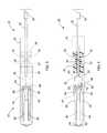
- FIG. 1is a top view of a medical system having a medical device for engaging tissue, constructed in accordance with the teachings of the present invention
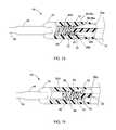
- FIG. 2is a top view similar to FIG. 1 , but showing the outer structures in dotted lines and the interior sections in solid lines and partial cross section;
- FIG. 3is a side view of the medical system and device depicted in FIG. 1 ;
- FIG. 4is a side view similar to FIG. 3 , but showing the outer structures in dotted lines and the interior structures in solid lines and partial cross section
- FIG. 5is a side view of a medical device that is part of the medical system depicted in FIGS. 1-4 ;
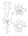
- FIG. 6is a front view of a housing forming a portion of the medical system and device depicted in FIGS. 1-5 ;
- FIG. 7is a perspective view of the housing depicted in FIG. 6 ;
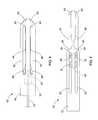
- FIGS. 8-12are side views showing operation of the medical system and device depicted in FIGS. 1-5 ;
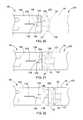
- FIGS. 13 and 14are top views, partially in cross-section, depicting operation of the medical system and device depicted in FIGS. 1-4 ;
- FIGS. 15 and 16are cross-sectional views showing operation of the medical system depicted in FIGS. 1-4 .
- FIG. 17is a perspective view of an alternate embodiment of a connection block forming a portion of the medical system of FIG. 1 ;
- FIG. 18is a front view showing the connection block of FIG. 17 ;
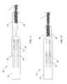
- FIG. 19is a perspective view of an alternate embodiment of the housing forming a portion of the medical system and medical device of FIG. 1 ;
- FIGS. 20-22show steps of operating the medical system depicted in FIGS. 17-19 ;
- FIG. 23is a perspective view of another alternate embodiment of a portion of the medical system and device depicted in FIG. 1 ;
- FIG. 24is a perspective view of another embodiment of the medical system depicted in FIG. 1 ;
- FIG. 25is a side view of the medical system depicted in FIG. 24 ;
- FIG. 26is a perspective view of a locking pin forming a portion of the medical system depicted in FIGS. 21-25 ;
- FIGS. 27-28are perspective views showing operation of an applicator for the locking pin depicted in FIG. 26 ;
- FIG. 29is a perspective view of an alternate embodiment of the applicator depicted in FIGS. 27 and 28 .
- proximal and distalas used herein are intended to have a reference point relative to the user. Specifically, throughout the specification, the terms “distal” and “distally” shall denote a position, direction, or orientation that is generally away from the user, and the terms “proximal” and “proximally” shall denote a position, direction, or orientation that is generally towards the user.
- FIGS. 1 through 4An exemplary medical system 20 having a medical device 40 for engaging tissue T ( FIG. 11 ) is shown in FIGS. 1 through 4 .
- the medical system 20 and device 40are generally sized and structured for operation through the working channel of an endoscope (not shown) or other scope, although the system 20 and device 40 may also be used alone or in conjunction with other elongate devices such as catheters, fiber-optic visualization systems, needles and the like.
- the medical system 20includes a drive wire 22 slidably housed within the distal end 23 of an elongated catheter 24 for selective connection to, and operation of, the medical device 40 .
- the medical device 40generally includes a housing 42 having a first jaw 44 and a second jaw 46 pivotally connected thereto for engaging the tissue T.
- the jaws 44 , 46have been shown as forming grasping forceps, although the jaws are intended to be used to clip tissue, e.g. to close an opening or for hemostasis. Accordingly, it will be recognized that the shape and structure of the jaws may take many forms and serve many purposes and functions, all in accordance with the teachings of the present invention.
- the drive wire 22slidably extends through the catheter 24 .
- wireany elongate control member capable of transmitting longitudinal force over a distance (such as is required in typical endoscopic, laparoscopic and similar procedures) may be used, and this includes plastic rods or tubes, single filament or multi-filament wires and the like.
- a connection block 26is slidably fitted within the distal end 23 of the catheter 24 and defines a bore 28 therethrough which slidably receives the drive wire 22 .
- the exterior of the connection block 26includes a recessed portion 27 , and two pins 30 (e.g., formed from stainless steel wire) are connected to the catheter 24 and positioned within the recessed portion 27 to limit the longitudinal movement of the connection block 26 .
- a distal end of the drive wire 22defines a distal head 32 that is sized larger than the drive wire 22 , and likewise larger than the bore 28 in the connection block 26 .
- the distal head 32is used to slide the connection block 26 within the catheter 24 to disconnect the medical device 40 from the medical system 20 .
- the housing 42 of the medical device 40is a tubular member defining an interior space 43 .
- a proximal end of the housing 42frictionally receives a distal end of the connection block 26 within the interior space 43 for selective connection therewith.
- the internal passageway 43 of the housing 42also receives the first and second jaws 44 , 46 and a driver 48 which is used to interconnect the drive wire 22 to the jaws 44 , 46 .
- the driver 48has a proximal portion which defines a socket 50 sized to receive enlarged distal head 32 of the drive wire 22 .
- two deflectable locking tabs 52are formed which rotate relative to the remainder of the driver 48 to increase or decrease the size of the socket 50 .
- the locking tabs 52may be separately formed and pivotally attached to the driver 48 , or may be integrally formed with the driver 48 and formed of a resilient material which flexes to permit rotation of the locking tabs 52 radially inwardly and radially outwardly.
- the locking tabs 52are plastically deformable, such that they may be locked to the drive wire 22 or to the housing 42 , as discussed further herein.
- a distal portion of the driver 48defines a rack 54 for engaging and operating the jaws 44 , 46 .
- the rack 54includes a central spine 56 having teeth 58 projecting away from the central spine 56 and on opposite sides of the spine 56 .
- One set of teeth 58 on one side of the spine 56generally operate the first jaw 44 while the other set of teeth 58 on the other side of the spine 56 operate the second jaw 46 .
- the rack 54may include a single set of teeth or other geared structures that interface with the jaws 44 , 46 .
- the first and second jaws 44 , 46include distal ends 60 , 62 that are structured to grasp and engage tissue, generally they have a talon shape as disclosed in No. 61/141,934 filed Dec. 31, 2008, the disclosure of which is incorporated herein by reference in its entirety.
- the proximal ends 64 , 66 of the first and second jaws 44 , 46each include a pinion gear 68 , 70 having a series of teeth.
- the teeth of the pinion 68 , 70mesh with the teeth of the rack 54 of the driver 48 such that longitudinal translation of the driver 48 induces rotation in the first and second jaws 44 , 46 relative to one another.
- distal translation of the driver 48causes the first and second jaws 44 , 46 to rotate outwardly away from each other, while proximal retraction of the driver 48 causes the first and second jaws 44 , 46 to rotate inwardly toward one another.
- Pins 80are fitted through each the proximal ends of the jaws 44 , 46 , to pivotally connect the jaws to the housing 42 .
- Other structures for forming a pivotal connectionmay be used, and preferably the pivotal connection is centrally arranged relative to the pinions 68 , 70 .
- the first and second jaws 44 , 46are also slidably attached to the housing 42 .
- the housing 42defines a first guide surface 82 for the first jaw 44 , and a second guide surface 84 for the second jaw 46 .
- the first and second guide surfaces 82 , 84are formed by elongated slots 82 a , 82 b , 84 a , 84 b formed in opposing sides of the housing 42 which leaves a thickness of the housing 42 exposed to serve as the guide surface.
- the slots 82 a , 82 bare aligned to receive the connecting pin 80 of the first jaw 44 , and likewise the slots 84 a , 84 b are aligned to receive the connecting pin 80 of the second jaw 46 .
- the ends of the slotsserve to restrict the longitudinal movement of the jaws 44 , 46 relative to the housing 42 .
- the proximal ends 64 , 66 of the jaws 44 , 46include apertures 72 , 74 which receive the pins 80 ( FIGS. 1, 2 and 3 ) that are used to slidably and pivotally connect the first and second jaws 44 , 46 to the housing 42 .
- the housing 42defines a third guide surface 86 which guides the longitudinal movement of the driver 48 within the housing 42 .
- the guide surface 86 in the depicted embodimentincludes a left guide surface 86 a and a right guide surface 86 b formed as C-shaped channels.
- the third guide surface 86transitions from a smaller proximal width to a larger distal width to define a shoulder 88 at the transition, which will be further described hereinbelow with reference to FIGS. 13 and 14 .
- the internal passageway 43 of the housing 42extends through the distal end of the housing, and through which the first and second jaws 44 , 46 can extend. Additionally, as shown in FIGS. 1 and 2 , the housing 42 defines opposing slots 45 which are sized to permit the first and second jaws 44 , 46 to pass therethrough when they rotate radially outwardly. Accordingly, it is also clear from FIGS. 1 and 2 that the housing 42 serves to block rotation of the first and second jaws 44 , 46 when they are entirely or partially contained within the internal passageway 43 of the housing 42 .
- Suitable plastics for forming the housinginclude, but are not limited to, polytetrafluorethylene (PTFE), expanded polytetrafluorethylene (EPTFE), polyethylene ether keytone (PEEK), polyvinylchloride (PVC), polycarbonate (PC), polyamide, polyimide, polyurethane, polyethylene (high, medium or low density), and suitable metals include stainless steel, nitinol and similar medical grade metals and alloys.
- PTFEpolytetrafluorethylene
- EPTFEexpanded polytetrafluorethylene
- PEEKpolyethylene ether keytone
- PVCpolyvinylchloride
- PCpolycarbonate
- suitable metalsinclude stainless steel, nitinol and similar medical grade metals and alloys.
- the first and second jaws 44 , 46are shown in a retracted position where they are substantially contained within the housing 42 .
- the distal ends 60 , 62 of the jaws 44 , 46may slightly project from the distal end of the housing 42 in their retracted positions, or they may be entirely positioned within the housing 42 .
- the distal head 32engages the driver 48 , and since the rack 54 of the driver 48 is meshed with the pinions 68 , 70 at the proximal ends 64 , 66 of the jaws 44 , 46 , the driver 48 and jaws 44 , 46 slide distally through the housing 42 because the housing 42 blocks their rotation. As previously mentioned, this longitudinal movement is guided by the first and second guide surfaces 82 , 84 which receive the pins 80 that slidably and pivotally connect the jaws 44 , 46 to the housing 42 .
- the first and second jaws 44 , 46have an extended position where the jaws substantially project from a distal end of the housing 42 , and their proximal ends 64 , 66 are positioned adjacent the distal end of the housing 42 . Accordingly, it will be seen that further distal advancement of drive wire 22 , and hence the driver 48 , causes the pinion 68 to rotate over the teeth 58 of the rack 54 . As best seen in FIG. 10 , the first and second jaws 44 , 46 rotate radially outwardly from each other into a tissue receiving position.
- the jaws 44 , 46are permitted to rotate a full 90°, thus forming at least a 180° between them. It will be recognized that through the sizing of the slots 45 and the construction of the rack 54 and pinions 68 , 70 , the first and second jaws 44 , 46 may rotate even further away from each other.
- the medical device 40 and its jaws 44 , 46may be positioned adjacent tissue T.
- the tissue Tmay be placed between the first and second jaws 44 , 46 and the jaws 44 , 46 rotated back towards their position shown in FIG. 9 .
- the tissue Thas been shown as a single layer, although multiple layers may be clipped between the jaws 44 , 46 .
- proximal retraction of the drive wire 22 and the driver 48again causes rotation of the first and second jaws 44 , 46 to grasp the tissue T therebetween.
- FIG. 12further proximal retraction of the drive wire 22 and driver 48 will cause the jaws 44 , 46 to move longitudinally in a proximal direction (to the left on the page in FIG. 12 ).
- the jaws 44 , 46may be locked in position and the drive wire 22 of the medical system 20 disconnected from the medical device 40 .
- the third guide surface 86(which guides the driver 48 ) includes a proximal portion 86 p and a distal portion 86 d .
- the proximal portion 86 p of the third guide surface 86has a width (measured up and down on the page in FIG. 13 ) that is greater than a width of the distal portion 86 d of the third guide 86 .
- the third guide surface 86is formed by opposing surfaces or C-shaped channels 86 a , 86 b of the housing 42 .
- the transition between the proximal portion 86 p and distal portion 86 ddefines a shoulder 88 , and namely two shoulders 88 a , 88 b on opposing sides of the housing 42 .
- the shoulders 88 a , 88 bare sized and positioned to engage the locking tabs 52 located on the driver 48 .
- the locking tabs 52are forced radially inwardly into firm frictional engagement with the drive wire 22 .
- the socket 50 formed by the driver 48 to receive the distal head 32has an entrance which is narrowed by the inward deflection of the locking tabs 52 .
- the drive wire 22is firmly engaged with the driver 48 and hence the first and second jaws 44 , 46 .
- the drive wire 22 and driver 48are retracted proximally, for example upon grasping tissue as shown in FIG.
- the proximal end of the driver 48is received within the proximal portion 86 p of the third guide surface 86 which has a larger width that permits outward movement of the locking tabs 52 .
- the locking tabs 52may be loosely and detachably connected to the distal head 32 of the drive wire 22 . That is, the proximal retraction of the jaws 44 , 46 will be limited by either the tissue T engaging the distal end of the housing 42 , or the pins 80 will abut the proximal ends of the slots 82 a , 82 b , 84 a , 84 b defining a first and second guide surfaces 82 , 84 .
- proximal movement of the jaws 44 , 46 and the driver 48when proximal movement of the jaws 44 , 46 and the driver 48 are thus limited, further proximal movement of the drive wire 22 and its distal head 32 may be used to withdraw the distal head 32 from the socket 50 of the driver 48 .
- This operationmay also be used to further deflect the locking tabs 52 radially outwardly, e.g. via plastic deformation into this outward position to maintain the closed configuration of the jaws.
- the locking tabs 52will abut the shoulders 88 a , 88 b of the third guide surface of the housing 42 to prevent further distal movement of the jaws 44 , 46 .
- connection block 26which is slidably fitted within the distal end 23 of the catheter 24 .
- Sufficient proximal force on the drive wire 22will overcome the frictional fit between the connection block 26 and the proximal end of the housing 42 , thus moving the connection block 26 proximally (to the right on the page of FIGS. 15 and 16 ) to retract the connection block 26 within the tubular connector 24 , as shown in FIG. 16 .
- the catheter 24can be used to provide a counterforce on the housing 42 while proximally retracting the drive wire 22 and connection block 26 .
- connection block 26may be fully disconnected from the medical device 40 , thereby leaving the first and second jaws 44 , 46 and the housing 42 in a state having the tissue T clipped between the jaws 44 , 46 and retained in vivo.
- the connection block 26is retained at the distal end 23 of the catheter 24 via the pins 30 , which are positioned within the recessed area 27 to engage the proximal and distal ends of the connection block 26 and limit its longitudinal movement.
- the elongated catheter 24(or other elongate tubular member such as a sheath, tube, scope or the like), which slidably encases the drive wire 22 , extends proximally therealong to a proximal end of the system 20 , and has a length suitable for placing the device 40 at any desired location within the body, while the proximal ends of drive wire 22 and catheter 24 are positioned outside of the body for use by the medical professional.
- Control handles(not shown) for controlling relative translation of the drive wire 22 and catheter 24 are well known in the art, and may be employed at the proximal end of the system 20 .
- a connection block 126is slidably fitted within the distal end 23 of the catheter 24 ( FIGS. 20-22 ) and defines a bore 128 therethrough ( FIG. 18 ) which slidably receives the drive wire 22 .
- the exterior of the connection block 126includes a recessed portion 127 defining a proximal flange 132 and a distal flange 134 .
- the distal flange 134is larger than the proximal flange 132 (longitudinally), and it is slightly smaller than an inner diameter of the tubular housing 142 of the clip device 140 (i.e. does not have a friction fit).
- a connection ring 136is attached to the distal flange 134 and includes a plurality of tabs 138 which project radially outwardly and connect to the housing 142 .
- the proximal end of the housing 142includes a plurality of slots 144 corresponding to the tabs 138 of the connection ring 136 .
- the slots 144extend longitudinally from the end surface of the housing 142 and include a narrowed region or throat 146 that is sized to retain the tabs 138 in a distal portion of the slots 144 .
- a plurality of slits 148may be formed in the housing 142 at the ends of the slots 144 to provide additional flexibility to allow the slots 144 to slightly enlarge as the tabs 138 pass through the throats 146 of the slots 144 .
- the housing 142may be formed of a suitable plastic or metal (or combination thereof) that is sufficiently flexible for passing the tabs 138 into the slots 144 , while also being sufficiently rigid to form the guide surfaces which guide the jaws and driver as previously described.
- the connection blockis initially positioned within the proximal end of housing 142 such that the tabs 138 are locked into the distal portions of the slots 144 and held in place by the throat 146 .
- the drive wire 22 and its distal head 32are retracted proximally to engage the connection block 126 (see, e.g., FIGS.
- connection block 126is moved proximally relative to the housing 142 such that the tabs 138 move past the throats 146 and into the proximal portions of the slots 144 , as shown in FIG. 21 .
- the clip device 40may be detached from the catheter 24 and drive wire 22 , as shown in FIG. 22 .
- connection block 226for a medical system 220 , shown in FIG. 23 , the block 226 again includes a bore 228 and a recessed portion 227 defined by a proximal flange 232 and a distal flange 234 .
- the distal flange 234is provided with an O-ring 236 or other similar gasket or compressible member (e.g. a disk or individual tabs made of an elastomer or rubber) that is fitted on the exterior of the distal flange 234 .
- the connection block 226may include a groove to receive the O-ring 236 , or it may be attached via friction fit, adhesives, bonding techniques such as plastic welding, or other mechanical connecting structures.
- the O-ring 236is sized to provide a friction fit between the connection block and the proximal end 244 of the housing 242 .
- the proximal end 244may also be formed with a chamfer 246 or other sloped surface to guide interconnection of the connection block 226 and the housing 242 .
- the drive wire 22 and its distal head 32could again be connected to the driver 48 and its socket 50 , thus permitting additional manipulation of the medical device to adjust the clipped tissue T.
- additional medical devicesmay be attached to the drive wire 22 and tubular connector 24 of the medical system 20 for deployment of the additional medical devices, e.g. multiple devices 40 for clipping the tissue T may be used to close a perforation or achieve hemostasis.
- the support ring 34FIGS. 1-4 ) fixed on the drive wire 22 can be used to limit the distal movement of the drive wire 22 , and can be distally advanced to a position abutting the connection block 26 .
- the drive wire 22 and support ring 34can be used to push the connection block 26 distally out of the tubular connector 24 so that it can be attached to the housing (e.g. 42 ) of a new medical device (e.g. 40 ), or the previously placed medical device 40 .
- the usermay manually press (i.e. with fingers or a tool) the connection block 26 distally out of the tubular connector 24 for connection to another medical device.
- FIGS. 24-29depict various alternate embodiments and devices that facilitate loading a clip device 40 within the medical system 20 in accordance with the foregoing.
- a catheter attachment 330takes the form of a tubular member which defines an interior passageway 332 which extends therethrough.
- the proximal end 331 of the catheter attachment 330is sized to be connected to the distal end of the catheter 24 , as shown in FIG. 25 (e.g. via friction fit, adhesives, plastic bonding or welding, mechanical connectors, etc.).
- the catheter attachment 330includes a pair of diametrically opposed openings 334 which provide access to the control wire 22 running through the catheter 24 and passageway 332 , as best seen in FIG. 25 .
- the catheter attachment 330also includes U-shaped cut-outs 336 in four places, the cut-outs 336 leaving tabs 338 .
- the tabs 338may be bent radially inwardly as shown in FIG. 25 , and thus can be used to replace the pin 30 in the catheter 24 shown in prior embodiments. That is, the tabs 338 project into the passageway 332 and fit within the recessed portion 127 of the connection plug 126 as was described with reference to FIG. 17-22 .
- the tabs 338limit the longitudinal movement of the connection block 126 , while permitting rotation of the connected block 126 and the control wire 22 and catheter 24 .
- the large openings 334 in the catheter attachment 330provide access to hold the connection block 126 in an extended position for attachment of another clip device 40 .
- a locking pin 350is shown which may be positioned through the openings 334 and the catheter attachment 330 for holding the connection block 126 in its extended position shown in FIG. 25 .
- the locking pin 350includes a main body 352 having a flange 354 projecting laterally therefrom. From the flange 354 projects a forked strut 356 which also projects laterally from the main body 352 .
- the forked strut 356includes two tines 358 that are spaced apart to define a slot 360 therebetween.
- the slot 360is sized to receive the drive wire 22 therein, and are also spaced to be entirely placed through the openings 334 in the catheter attachment 330 . In this manner, the locking pin 350 prevents proximal movement of the connection block 126 to hold it in place for attachment of another device 40 for clipping the tissue.
- FIGS. 27 and 28depict an applicator 400 for placing the locking pin 350 through the opening 334 in the catheter attachment 330 .
- the applicator 400generally includes a left body 402 and a right body 404 , each of which define openings 406 , 408 for receiving fingers of a medical professional.
- the left and right bodies 402 , 404are slidably connected to one another, for example using a plurality of rods 410 projecting from the left body 402 which are slidably received within passageways 412 formed in the right body 404 .
- the left and right bodies 402 , 404also included channels for receiving the catheter 24 and catheter attachment 330 for placement of the locking pin 350 .
- the channelsinclude a lower portion 414 which is sized to receive the catheter 24 , and an upper portion 416 which is sized to receive the catheter attachment 330 .
- the upper channel portions 416also include depressions which receive the locking pin 350 , and in particular the left body 402 includes a recess 418 a for receiving the main body 352 and flange 354 of the locking pin 350 , while the right body 404 includes a recess 418 b for receiving the ends of the tines 358 of the locking pin 350 . Accordingly, and as shown in FIG.
- the distal end of the catheter 24 and its catheter attachment 330may be loaded in the channels 414 , 416 , of the right body 404 , and then the left body 402 moved into engagement with the right body 404 such that the locking pin 350 is placed through the openings 334 in the catheter attachment 330 such that the tines 358 extend around the control wire 22 and the proximal movement of the connection block 126 is prevented, thus allowing the housing 42 , 142 of a clip device 40 , 140 to be pressed onto the connection block 26 , 126 , 226 .
- FIG. 29depicts a perspective view of another embodiment of an applicator 500 for maintaining the connection block 26 , 126 , 226 in an extended position.
- the catheter 24includes a catheter attachment 330 as previously described.
- the applicator 500is a single grasping member 502 which has recesses 504 on opposing sides for grasping between two fingers of the medical professional.
- the recesses 504open to one side of the body 502 , while the opposing side includes a fork strut 556 having two tines 558 spaced apart to define a slot 560 .
- the tines 558are sized to be passed through the openings 334 in the catheter attachment 330 such that the drive wire 22 is received within the slot 560 , whereby proximal movement of the connection block 126 is blocked to maintain its extended position for attachment of another device 40 for clipping tissue.
- connection/disconnection mechanismsmay be found in US. Appl. No. 61/391,875 and Appl. No. 61/391,881, the disclosures of which are hereby incorporated by reference in their entirety.
Landscapes
- Health & Medical Sciences (AREA)
- Life Sciences & Earth Sciences (AREA)
- Surgery (AREA)
- Molecular Biology (AREA)
- Engineering & Computer Science (AREA)
- Biomedical Technology (AREA)
- Heart & Thoracic Surgery (AREA)
- Medical Informatics (AREA)
- Nuclear Medicine, Radiotherapy & Molecular Imaging (AREA)
- Animal Behavior & Ethology (AREA)
- General Health & Medical Sciences (AREA)
- Public Health (AREA)
- Veterinary Medicine (AREA)
- Reproductive Health (AREA)
- Vascular Medicine (AREA)
- Surgical Instruments (AREA)
Abstract
Description
This application is a Divisional of U.S. patent application Ser. No. 13/270,834 filed on Oct. 11, 2011, which is a Continuation-In-Part of U.S. patent application Ser. No. 12/971,873 filed on Dec. 17, 2010, and also a Continuation-In-Part of U.S. patent application Ser. No. 14/285,009 filed May 22, 2014, which is a Divisional of Ser. No. 12/971,873, and also claims the benefit of U.S. Provisional Patent Application Ser. No. 61/289,297 filed on Dec. 22, 2009, and the benefit of U.S. Provisional Patent Application Ser. No. 61/391,878 filed on Oct. 11, 2010. All of the foregoing applications are hereby incorporated by reference.
Conventionally, a clip may be introduced into a body cavity through an endoscope to grasp living tissue of a body cavity for hemostasis, marking, and/or ligating. Such clips are often known as surgical clips, endoscopic clips, hemostasis clips and vascular clips. In addition, clips are now being used in a number of applications related to gastrointestinal bleeding such as peptic ulcers, Mallory-Weiss tears, Dieulafoy's lesions, angiomas, post-papillotomy bleeding, and small varices with active bleeding. Clips have also been attempted for use in closing perforations in the stomach
Gastrointestinal bleeding is a somewhat common and serious condition that is often fatal if left untreated. This problem has prompted the development of a number of endoscopic therapeutic approaches to achieve hemostasis such as the injection of sclerosing agents and contact thermo-coagulation techniques. Although such approaches are often effective, bleeding continues for many patients and corrective surgery therefore becomes necessary. Because surgery is an invasive technique that is associated with a high morbidity rate and many other undesirable side effects, there exists a need for highly effective, less invasive procedures.
Mechanical hemostatic devices such as clips have been used in various parts of the body, including gastrointestinal applications. One of the problems associated with conventional hemostatic devices and clips, however, is that many devices are not strong enough to cause permanent hemostasis. Further, clips have also been attempted for use in closing perforations in the stomach or gastrointestinal structures, but unfortunately traditional clips suffer from difficult placement and the capability to grasp a limited amount of tissue, potentially resulting in incomplete closure.
The invention may include any of the following aspects in various combinations and may also include any other aspect described below in the written description or in the attached drawings.
In a first aspect, a medical device is provided for engaging tissue, the medical device including a housing, first and second jaws, a driver, an elongated drive wire and an elongated tubular member. The housing defines an internal passageway and a longitudinal axis extending between proximal and distal ends of the housing. The first and second jaws are rotatable relative to the housing and have proximal and distal ends. The driver is engaged with the proximal ends of the first and second jaws, wherein longitudinal movement of the driver rotates the first and second jaws relative to the housing. The elongated drive wire is selectively connected to the driver for longitudinal movement therewith, and the drive wire has an enlarged portion proximate a distal end of the drive wire. The elongate tubular member defines a lumen sized to slidably receive a connection block. The connection block defines a bore slidably receiving the drive wire, wherein the enlarged portion of the drive wire has a size that is larger than the bore and is positioned on a distal side of the connection block. The connection block is operable between an extended position and a retracted position. The connection block projects from the tubular member in the extended position and is structured to engage a proximal end of the housing. The connection block is positioned within the lumen of the tubular member in the retracted position and disengaged from the housing. The enlarged portion of the drive wire engages the connection block upon proximal retraction of the drive wire to operate the tubular member from its extended position to its retracted position and disengage the connection block from the housing.
According to further detailed aspects, the connection block is preferably sized to frictionally engage the housing. The connection block may include a connection ring having a plurality of tabs, wherein the housing includes a plurality of slots extending to a proximal end of the housing that receive the plurality of tabs. The plurality of slots may each include a narrowed throat separating proximal and distal portions of the slots. The housing may further include a plurality of slits formed therein, the slits each connected to a distal portion of the slots to improve flexibility of the housing. The connection block includes a distal flange and a proximal flange defining a reduced diameter portion therebetween, and the tubular member includes one of a pin and a tab projecting into the lumen and positioned within the reduced diameter portion to limit longitudinal movement of the connection block. The connection block may also include a compressible member attached thereto and sized to be compressed between an interior of the housing and an exterior of the connection block.
According to further detailed aspects, the system may also include an attachment member attached to a distal end of the tubular member, the attachment member including a passageway in communication with the lumen of the tubular member. The attachment member preferably includes diametrically opposing openings between ends of the attachment member in communication with the passageway. The connection block includes a distal flange and a proximal flange defining a reduced diameter portion therebetween, and the attachment member preferably includes at least one tab projecting into the lumen and positioned within the reduced diameter portion to limit longitudinal movement of the connection block, the tab unitarily and integrally formed with the attachment member. The system may also include a locking pin having a forked strut defined by two tines having a slot therebetween. The slot is sized to receive the drive wire therein, and the forked strut sized to pass through the opposing openings in the attachment member and limit longitudinal movement of the connection block. The system may still further include an applicator having a left body slidably attached to a right body, the left and right bodies including channels sized and shaped to receive portions of the tubular member and attachment member and maintain their position relative to the applicator. The channels are also sized and shaped to receive portions of the locking pin, whereby relative translation of the left and right bodies positions the forked strut of the locking pin into, or out of, the opposing openings in the attachment member. Alternatively, the applicator may simply have a main body and a forked strut projecting from the main body, the forked strut defined by two tines having a slot therebetween, the slot sized to receive the drive wire therein, the forked strut sized to pass through the opposing opening in the attachment member and limit longitudinal movement of the connection block.
According to still further detailed aspects, the enlarged portion of the drive wire is an enlarged distal head, and the driver includes a socket facing proximally and receiving the distal head. The driver is constructed of a resilient material that flexes to adjust the size of the socket. The socket is sized to selectively receive the enlarged distal head of the drive wire. A locking tab may be positioned at an entrance to the socket and moves to vary the size of the entrance. Preferably, the driver includes two locking tabs on opposing sides of the socket, and the housing includes a guide surface guiding the longitudinal movement of the driver, the guide surface including two surfaces on opposing sides of the housing corresponding to the two locking tabs. The housing may also define a shoulder at the transition between the proximal portion and distal portion of the guide surface, wherein the locking tab is positioned to engage the shoulder to limit longitudinal movement of the driver. The shoulder preferably deflects the tab to a position into engagement with the shoulder when a distally directed longitudinal force on the driver reaches a predetermined force to permit longitudinal movement of the driver and the first and second jaws in a distal direction.
The accompanying drawings incorporated in and forming a part of the specification illustrate several aspects of the present invention, and together with the description serve to explain the principles of the invention. In the drawings:
The terms “proximal” and “distal” as used herein are intended to have a reference point relative to the user. Specifically, throughout the specification, the terms “distal” and “distally” shall denote a position, direction, or orientation that is generally away from the user, and the terms “proximal” and “proximally” shall denote a position, direction, or orientation that is generally towards the user.
An exemplarymedical system 20 having amedical device 40 for engaging tissue T (FIG. 11 ) is shown inFIGS. 1 through 4 . Themedical system 20 anddevice 40 are generally sized and structured for operation through the working channel of an endoscope (not shown) or other scope, although thesystem 20 anddevice 40 may also be used alone or in conjunction with other elongate devices such as catheters, fiber-optic visualization systems, needles and the like. Generally, themedical system 20 includes adrive wire 22 slidably housed within thedistal end 23 of anelongated catheter 24 for selective connection to, and operation of, themedical device 40. As will be described in further detail herein, themedical device 40 generally includes ahousing 42 having afirst jaw 44 and asecond jaw 46 pivotally connected thereto for engaging the tissue T. Generally, thejaws
In themedical system 20, thedrive wire 22 slidably extends through thecatheter 24. Although the term “wire” is used to refer to thedrive wire 22, it will be recognized that any elongate control member capable of transmitting longitudinal force over a distance (such as is required in typical endoscopic, laparoscopic and similar procedures) may be used, and this includes plastic rods or tubes, single filament or multi-filament wires and the like. Aconnection block 26 is slidably fitted within thedistal end 23 of thecatheter 24 and defines abore 28 therethrough which slidably receives thedrive wire 22. The exterior of theconnection block 26 includes a recessedportion 27, and two pins30 (e.g., formed from stainless steel wire) are connected to thecatheter 24 and positioned within the recessedportion 27 to limit the longitudinal movement of theconnection block 26.
A distal end of thedrive wire 22 defines adistal head 32 that is sized larger than thedrive wire 22, and likewise larger than thebore 28 in theconnection block 26. As will be described later herein, thedistal head 32 is used to slide theconnection block 26 within thecatheter 24 to disconnect themedical device 40 from themedical system 20. As also seen inFIGS. 1-4 , thehousing 42 of themedical device 40 is a tubular member defining aninterior space 43. A proximal end of thehousing 42 frictionally receives a distal end of theconnection block 26 within theinterior space 43 for selective connection therewith.
Theinternal passageway 43 of thehousing 42 also receives the first andsecond jaws driver 48 which is used to interconnect thedrive wire 22 to thejaws FIGS. 1, 2 and 5 , thedriver 48 has a proximal portion which defines asocket 50 sized to receive enlargeddistal head 32 of thedrive wire 22. At the proximal entrance of thesocket 50, twodeflectable locking tabs 52 are formed which rotate relative to the remainder of thedriver 48 to increase or decrease the size of thesocket 50. The lockingtabs 52 may be separately formed and pivotally attached to thedriver 48, or may be integrally formed with thedriver 48 and formed of a resilient material which flexes to permit rotation of the lockingtabs 52 radially inwardly and radially outwardly. Preferably the lockingtabs 52 are plastically deformable, such that they may be locked to thedrive wire 22 or to thehousing 42, as discussed further herein.
A distal portion of thedriver 48 defines arack 54 for engaging and operating thejaws rack 54 includes acentral spine 56 havingteeth 58 projecting away from thecentral spine 56 and on opposite sides of thespine 56. One set ofteeth 58 on one side of thespine 56 generally operate thefirst jaw 44 while the other set ofteeth 58 on the other side of thespine 56 operate thesecond jaw 46. It will be recognized that therack 54 may include a single set of teeth or other geared structures that interface with thejaws
As best seen inFIG. 5 , the first andsecond jaws second jaws pinion gear pinion rack 54 of thedriver 48 such that longitudinal translation of thedriver 48 induces rotation in the first andsecond jaws driver 48 causes the first andsecond jaws driver 48 causes the first andsecond jaws Pins 80 are fitted through each the proximal ends of thejaws housing 42. Other structures for forming a pivotal connection may be used, and preferably the pivotal connection is centrally arranged relative to thepinions
In addition to thejaws housing 42, the first andsecond jaws housing 42. As best seen inFIGS. 6 and 7 (and in conjunction withFIGS. 1-4 ) thehousing 42 defines afirst guide surface 82 for thefirst jaw 44, and asecond guide surface 84 for thesecond jaw 46. As seen inFIG. 3 , the first and second guide surfaces82,84 are formed byelongated slots housing 42 which leaves a thickness of thehousing 42 exposed to serve as the guide surface. Theslots pin 80 of thefirst jaw 44, and likewise theslots pin 80 of thesecond jaw 46. The ends of the slots, for example distal ends92,94 shown inFIG. 7 , serve to restrict the longitudinal movement of thejaws housing 42. The proximal ends64,66 of thejaws apertures FIGS. 1, 2 and 3 ) that are used to slidably and pivotally connect the first andsecond jaws housing 42.
It can also be seen inFIGS. 6 and 7 that thehousing 42 defines athird guide surface 86 which guides the longitudinal movement of thedriver 48 within thehousing 42. Theguide surface 86 in the depicted embodiment includes aleft guide surface 86aand aright guide surface 86bformed as C-shaped channels. As shown inFIG. 7 , thethird guide surface 86 transitions from a smaller proximal width to a larger distal width to define ashoulder 88 at the transition, which will be further described hereinbelow with reference toFIGS. 13 and 14 .
As also shown inFIG. 6 , theinternal passageway 43 of thehousing 42 extends through the distal end of the housing, and through which the first andsecond jaws FIGS. 1 and 2 , thehousing 42 defines opposingslots 45 which are sized to permit the first andsecond jaws FIGS. 1 and 2 that thehousing 42 serves to block rotation of the first andsecond jaws internal passageway 43 of thehousing 42. Suitable plastics for forming the housing include, but are not limited to, polytetrafluorethylene (PTFE), expanded polytetrafluorethylene (EPTFE), polyethylene ether keytone (PEEK), polyvinylchloride (PVC), polycarbonate (PC), polyamide, polyimide, polyurethane, polyethylene (high, medium or low density), and suitable metals include stainless steel, nitinol and similar medical grade metals and alloys.
Operation of themedical device 40 will now be described with reference toFIGS. 8-12 . As shown inFIG. 8 , the first andsecond jaws housing 42. Depending on the application, the distal ends60,62 of thejaws housing 42 in their retracted positions, or they may be entirely positioned within thehousing 42. When thedrive wire 22 is translated distally (to the right on the page inFIG. 8 ) thedistal head 32 engages thedriver 48, and since therack 54 of thedriver 48 is meshed with thepinions jaws driver 48 andjaws housing 42 because thehousing 42 blocks their rotation. As previously mentioned, this longitudinal movement is guided by the first and second guide surfaces82,84 which receive thepins 80 that slidably and pivotally connect thejaws housing 42.
As shown inFIG. 9 , the first andsecond jaws housing 42, and their proximal ends64,66 are positioned adjacent the distal end of thehousing 42. Accordingly, it will be seen that further distal advancement ofdrive wire 22, and hence thedriver 48, causes thepinion 68 to rotate over theteeth 58 of therack 54. As best seen inFIG. 10 , the first andsecond jaws slots 45 at the distal end of thehousing 42, thejaws slots 45 and the construction of therack 54 andpinions second jaws
In the tissue receiving configuration shown inFIG. 10 , themedical device 40 and itsjaws FIG. 11 , the tissue T may be placed between the first andsecond jaws jaws FIG. 9 . The tissue T has been shown as a single layer, although multiple layers may be clipped between thejaws drive wire 22 and thedriver 48 again causes rotation of the first andsecond jaws FIG. 12 , further proximal retraction of thedrive wire 22 anddriver 48 will cause thejaws FIG. 12 ).
In order for themedical device 40 to serve as a clip and maintain its grasp on the tissue T, or to maintain the clipping of two layers of tissue against each other, thejaws drive wire 22 of themedical system 20 disconnected from themedical device 40. As shown inFIG. 13 , the third guide surface86 (which guides the driver48) includes aproximal portion 86pand adistal portion 86d. Theproximal portion 86pof thethird guide surface 86 has a width (measured up and down on the page inFIG. 13 ) that is greater than a width of thedistal portion 86dof thethird guide 86. As previously discussed, thethird guide surface 86 is formed by opposing surfaces or C-shapedchannels housing 42. The transition between theproximal portion 86panddistal portion 86ddefines ashoulder 88, and namely twoshoulders 88a,88bon opposing sides of thehousing 42. Theshoulders 88a,88bare sized and positioned to engage the lockingtabs 52 located on thedriver 48.
As shown inFIG. 13 , when thedriver 48 is located within thedistal portion 86dof thethird guide surface 86, the lockingtabs 52 are forced radially inwardly into firm frictional engagement with thedrive wire 22. Stated another way, thesocket 50 formed by thedriver 48 to receive thedistal head 32 has an entrance which is narrowed by the inward deflection of the lockingtabs 52. In this state depicted inFIG. 13 , thedrive wire 22 is firmly engaged with thedriver 48 and hence the first andsecond jaws drive wire 22 anddriver 48 are retracted proximally, for example upon grasping tissue as shown inFIG. 12 , the proximal end of thedriver 48 is received within theproximal portion 86pof thethird guide surface 86 which has a larger width that permits outward movement of the lockingtabs 52. Accordingly, in the state depicted inFIG. 14 , the lockingtabs 52 may be loosely and detachably connected to thedistal head 32 of thedrive wire 22. That is, the proximal retraction of thejaws housing 42, or thepins 80 will abut the proximal ends of theslots jaws driver 48 are thus limited, further proximal movement of thedrive wire 22 and itsdistal head 32 may be used to withdraw thedistal head 32 from thesocket 50 of thedriver 48. This operation may also be used to further deflect the lockingtabs 52 radially outwardly, e.g. via plastic deformation into this outward position to maintain the closed configuration of the jaws. In the event the natural elasticity of the tissue T tends to pull thejaws tabs 52 will abut theshoulders 88a,88bof the third guide surface of thehousing 42 to prevent further distal movement of thejaws
Turning now toFIGS. 15 and 16 , upon still further proximal retraction of thedrive wire 22 anddistal head 32, the enlargeddistal head 32 will abut theconnection block 26 which is slidably fitted within thedistal end 23 of thecatheter 24. Sufficient proximal force on thedrive wire 22 will overcome the frictional fit between theconnection block 26 and the proximal end of thehousing 42, thus moving theconnection block 26 proximally (to the right on the page ofFIGS. 15 and 16 ) to retract theconnection block 26 within thetubular connector 24, as shown inFIG. 16 . Thecatheter 24 can be used to provide a counterforce on thehousing 42 while proximally retracting thedrive wire 22 andconnection block 26. Accordingly, thedrive wire 22,catheter 24 andconnection block 26 may be fully disconnected from themedical device 40, thereby leaving the first andsecond jaws housing 42 in a state having the tissue T clipped between thejaws connection block 26 is retained at thedistal end 23 of thecatheter 24 via thepins 30, which are positioned within the recessedarea 27 to engage the proximal and distal ends of theconnection block 26 and limit its longitudinal movement.
The elongated catheter24 (or other elongate tubular member such as a sheath, tube, scope or the like), which slidably encases thedrive wire 22, extends proximally therealong to a proximal end of thesystem 20, and has a length suitable for placing thedevice 40 at any desired location within the body, while the proximal ends ofdrive wire 22 andcatheter 24 are positioned outside of the body for use by the medical professional. Control handles (not shown) for controlling relative translation of thedrive wire 22 andcatheter 24 are well known in the art, and may be employed at the proximal end of thesystem 20.
In another embodiment of amedical system 120 shown inFIGS. 17-22 , aconnection block 126 is slidably fitted within thedistal end 23 of the catheter24 (FIGS. 20-22 ) and defines abore 128 therethrough (FIG. 18 ) which slidably receives thedrive wire 22. As best seen inFIGS. 17-18 , the exterior of theconnection block 126 includes a recessedportion 127 defining aproximal flange 132 and adistal flange 134. In this embodiment, thedistal flange 134 is larger than the proximal flange132 (longitudinally), and it is slightly smaller than an inner diameter of thetubular housing 142 of the clip device140 (i.e. does not have a friction fit). Here, aconnection ring 136 is attached to thedistal flange 134 and includes a plurality oftabs 138 which project radially outwardly and connect to thehousing 142.
As best seen inFIG. 19 , the proximal end of thehousing 142 includes a plurality ofslots 144 corresponding to thetabs 138 of theconnection ring 136. Theslots 144 extend longitudinally from the end surface of thehousing 142 and include a narrowed region orthroat 146 that is sized to retain thetabs 138 in a distal portion of theslots 144. A plurality ofslits 148 may be formed in thehousing 142 at the ends of theslots 144 to provide additional flexibility to allow theslots 144 to slightly enlarge as thetabs 138 pass through thethroats 146 of theslots 144. Thehousing 142 may be formed of a suitable plastic or metal (or combination thereof) that is sufficiently flexible for passing thetabs 138 into theslots 144, while also being sufficiently rigid to form the guide surfaces which guide the jaws and driver as previously described. As shown in the sequence ofFIGS. 20-22 , the connection block is initially positioned within the proximal end ofhousing 142 such that thetabs 138 are locked into the distal portions of theslots 144 and held in place by thethroat 146. When thedrive wire 22 and itsdistal head 32 are retracted proximally to engage the connection block126 (see, e.g.,FIGS. 15-16 ), theconnection block 126 is moved proximally relative to thehousing 142 such that thetabs 138 move past thethroats 146 and into the proximal portions of theslots 144, as shown inFIG. 21 . With further proximal movement of thedrive wire 22 and/orcatheter 24, theclip device 40 may be detached from thecatheter 24 and drivewire 22, as shown inFIG. 22 .
In yet another embodiment of aconnection block 226 for amedical system 220, shown inFIG. 23 , theblock 226 again includes abore 228 and a recessedportion 227 defined by aproximal flange 232 and adistal flange 234. In this embodiment, thedistal flange 234 is provided with an O-ring 236 or other similar gasket or compressible member (e.g. a disk or individual tabs made of an elastomer or rubber) that is fitted on the exterior of thedistal flange 234. Theconnection block 226 may include a groove to receive the O-ring 236, or it may be attached via friction fit, adhesives, bonding techniques such as plastic welding, or other mechanical connecting structures. The O-ring 236 is sized to provide a friction fit between the connection block and theproximal end 244 of thehousing 242. Theproximal end 244 may also be formed with achamfer 246 or other sloped surface to guide interconnection of theconnection block 226 and thehousing 242.
It will be recognized by those skilled in the art that thedrive wire 22 and itsdistal head 32 could again be connected to thedriver 48 and itssocket 50, thus permitting additional manipulation of the medical device to adjust the clipped tissue T. Likewise, additional medical devices may be attached to thedrive wire 22 andtubular connector 24 of themedical system 20 for deployment of the additional medical devices, e.g.multiple devices 40 for clipping the tissue T may be used to close a perforation or achieve hemostasis. Generally, the support ring34 (FIGS. 1-4 ) fixed on thedrive wire 22 can be used to limit the distal movement of thedrive wire 22, and can be distally advanced to a position abutting theconnection block 26. As such, thedrive wire 22 andsupport ring 34 can be used to push theconnection block 26 distally out of thetubular connector 24 so that it can be attached to the housing (e.g.42) of a new medical device (e.g.40), or the previously placedmedical device 40. Alternatively, the user may manually press (i.e. with fingers or a tool) theconnection block 26 distally out of thetubular connector 24 for connection to another medical device.
Thelarge openings 334 in thecatheter attachment 330 provide access to hold theconnection block 126 in an extended position for attachment of anotherclip device 40. Turning toFIG. 26 , alocking pin 350 is shown which may be positioned through theopenings 334 and thecatheter attachment 330 for holding theconnection block 126 in its extended position shown inFIG. 25 . Thelocking pin 350 includes amain body 352 having aflange 354 projecting laterally therefrom. From theflange 354 projects a forkedstrut 356 which also projects laterally from themain body 352. The forkedstrut 356 includes twotines 358 that are spaced apart to define aslot 360 therebetween. Theslot 360 is sized to receive thedrive wire 22 therein, and are also spaced to be entirely placed through theopenings 334 in thecatheter attachment 330. In this manner, the lockingpin 350 prevents proximal movement of theconnection block 126 to hold it in place for attachment of anotherdevice 40 for clipping the tissue.
Finally,FIG. 29 depicts a perspective view of another embodiment of anapplicator 500 for maintaining theconnection block FIGS. 24-28 , thecatheter 24 includes acatheter attachment 330 as previously described. Here, theapplicator 500 is a single graspingmember 502 which hasrecesses 504 on opposing sides for grasping between two fingers of the medical professional. Therecesses 504 open to one side of thebody 502, while the opposing side includes afork strut 556 having twotines 558 spaced apart to define aslot 560. As with the prior embodiment, thetines 558 are sized to be passed through theopenings 334 in thecatheter attachment 330 such that thedrive wire 22 is received within theslot 560, whereby proximal movement of theconnection block 126 is blocked to maintain its extended position for attachment of anotherdevice 40 for clipping tissue.
Additional embodiments of the connection/disconnection mechanisms and themedical system 20 may be found in US. Appl. No. 61/391,875 and Appl. No. 61/391,881, the disclosures of which are hereby incorporated by reference in their entirety.
The foregoing description of various embodiments of the invention has been presented for purposes of illustration and description. It is not intended to be exhaustive or to limit the invention to the precise embodiments disclosed. Numerous modifications or variations are possible in light of the above teachings. The embodiments discussed were chosen and described to provide the best illustration of the principles of the invention and its practical application to thereby enable one of ordinary skill in the art to utilize the invention in various embodiments and with various modifications as are suited to the particular use contemplated. All such modifications and variations are within the scope of the invention as determined by the appended claims when interpreted in accordance with the breadth to which they are fairly, legally, and equitably entitled.
Claims (18)
1. A medical system for engaging tissue, the medical system comprising:
a housing defining an internal passageway and a longitudinal axis extending between proximal and distal ends of the housing, the housing including a guide surface along the internal passageway, the guide surface including a proximal section and a distal section;
a first jaw pivotally connected to the housing, the first jaw having proximal and distal ends;
a second jaw pivotally connected to the housing, the second jaw having proximal and distal ends;
a driver engaged with the proximal ends of the first and second jaws, longitudinal movement of the driver rotating the first and second jaws relative to the housing, the longitudinal movement of the driver guided by the guide surface of the housing, the driver including a socket facing proximally and constructed of a resilient material that is flexible;
an elongated drive wire selectively connected to the driver for longitudinal movement therewith, the drive wire having an enlarged portion proximate a distal end of the drive wire, the enlarged portion selectively received within the socket of the driver;
a tubular member defining a lumen sized to slidably receive a connection block, the connection block defining a bore slidably receiving the drive wire, the enlarged portion of the drive wire having a size that is larger than the bore and positioned on a distal side of the connection block, the connection block operable between an extended position and a retracted position, the connection block projecting from the tubular member in the extended position and structured to engage a proximal end of the housing, the connection block positioned within the lumen of the tubular member in the retracted position and disengaged from the housing; and
the medical system operable between four states corresponding to four longitudinal positions of the enlarged portion of the drive wire, a first longitudinal position being distal to a second longitudinal position, the second longitudinal position being distal to a third longitudinal position, and the third longitudinal position being distal to a fourth longitudinal position;
wherein, in the first longitudinal position, the enlarged portion is located in the distal section of the guide surface and the socket firmly engages the drive wire;
wherein, in the second longitudinal position, the enlarged portion is located in the proximal section of the guide surface and the socket loosely and detachably engages the drive wire;
wherein, in the third longitudinal position, the socket is disengaged from the enlarged portion of the drive wire; and
wherein, in the fourth longitudinal position, the enlarged portion of the drive wire engages the connection block to operate the connection block from its extended position to its retracted position and disengage the connection block from the housing.
2. The medical system ofclaim 1 , wherein the first and second jaws are both slidably and pivotally connected to the housing, the first and second jaws configured to slide longitudinally relative to the housing.
3. The medical system ofclaim 1 , wherein the distal section of the guide surface is sized relative to the socket such that, when the socket is within the distal section, the socket non-releasably engages the enlarged portion of the drive wire.
4. The medical system ofclaim 1 , wherein the distal section has a smaller effective diameter than the proximal section of the guide surface.
5. The medical system ofclaim 1 , wherein the driver includes a locking tab positioned at an entrance to the socket that moves to vary the size of the entrance, and wherein the locking tab is moved radially inwardly when the driver and socket move distally from the proximal section to the distal section of the guide surface.
6. The medical system ofclaim 5 , wherein the distal section of the guide surface is sized relative to the socket such that, when the socket is within the distal section, the locking tab is pressed against the drive wire.
7. The medical system ofclaim 5 , wherein the driver includes two locking tabs on opposing sides of the entrance to the socket, and wherein the two locking tabs are moved radially inwardly by the distal section of the guide surface.
8. The medical system ofclaim 5 , wherein the housing defines a shoulder at a transition between the proximal section and distal section of the guide surface, and wherein the locking tab is positioned to engage the shoulder to limit longitudinal movement of the driver.
9. The medical system ofclaim 5 , wherein the locking tab is plastically deformable.
10. The medical system ofclaim 5 , wherein the shoulder deflects the tab radially inwardly to a position into engagement with the drive wire when a distally directed longitudinal force on the driver reaches a predetermined force to permit longitudinal movement of the driver and the first and second jaws in a distal direction.
11. The medical system ofclaim 10 , wherein, when the socket is located in the proximal section of the guide surface and a proximally directed longitudinal force on the drive wire reaches a predetermined force, the enlarged portion of the drive wire deflects the tab radially outwardly such that the drive wire is releasably connected to the driver.
12. The medical system ofclaim 1 , wherein the first and second jaws are slidably and pivotally connected to the housing, and wherein the first and second jaws are non-detachably connected to the housing.
13. The medical system ofclaim 1 , wherein the guide surface is defined by two grooves formed on opposite sides of the internal passageway.
14. The medical system ofclaim 1 , wherein the driver includes a locking tab positioned at an entrance to the socket that moves to vary the size of the entrance, and wherein the entrance has a smallest size in the first longitudinal position, and a largest size in the third longitudinal position, and wherein the locking tabs of the socket have a natural, unbiased configuration where the socket is engaged with the drive wire.
15. The medical system ofclaim 14 , wherein the locking tab is pressed against the drive wire in the first longitudinal position.
16. The medical system ofclaim 14 , wherein the guide surface includes a proximal section and a distal section, the distal section having a smaller effective diameter than the proximal section of the guide surface.
17. The medical system ofclaim 1 , wherein the connection block includes a distal flange and a proximal flange defining a reduced diameter portion therebetween, and wherein the tubular member includes one of a pin and a tab projecting into the lumen and positioned within the reduced diameter portion to limit longitudinal movement of the connection block.
18. The medical system ofclaim 17 , further comprising a locking device having a forked strut defined by two tines having a slot therebetween, the slot sized to receive the drive wire therein, the tubular member including an opening therein sized to receive the forked strut in a position to limit longitudinal movement of the connection block while the connection block projects from the tubular member.
Priority Applications (3)
| Application Number | Priority Date | Filing Date | Title |
|---|---|---|---|
| US14/568,841US9955977B2 (en) | 2009-12-22 | 2014-12-12 | Medical devices with detachable pivotable jaws |
| US15/915,749US11129624B2 (en) | 2009-12-22 | 2018-03-08 | Medical devices with detachable pivotable jaws |
| US17/409,049US12070224B2 (en) | 2009-12-22 | 2021-08-23 | Medical devices with detachable pivotable jaws |
Applications Claiming Priority (7)
| Application Number | Priority Date | Filing Date | Title |
|---|---|---|---|
| US28929709P | 2009-12-22 | 2009-12-22 | |
| US39187510P | 2010-10-11 | 2010-10-11 | |
| US39187810P | 2010-10-11 | 2010-10-11 | |
| US12/971,873US8771293B2 (en) | 2009-12-22 | 2010-12-17 | Medical devices with detachable pivotable jaws |
| US13/270,834US8939997B2 (en) | 2010-10-11 | 2011-10-11 | Medical devices with detachable pivotable jaws |
| US14/285,009US9375219B2 (en) | 2009-12-22 | 2014-05-22 | Medical devices with detachable pivotable jaws |
| US14/568,841US9955977B2 (en) | 2009-12-22 | 2014-12-12 | Medical devices with detachable pivotable jaws |
Related Parent Applications (2)
| Application Number | Title | Priority Date | Filing Date |
|---|---|---|---|
| US13/270,834DivisionUS8939997B2 (en) | 2009-12-22 | 2011-10-11 | Medical devices with detachable pivotable jaws |
| US14/285,009Continuation-In-PartUS9375219B2 (en) | 2009-12-22 | 2014-05-22 | Medical devices with detachable pivotable jaws |
Related Child Applications (2)
| Application Number | Title | Priority Date | Filing Date |
|---|---|---|---|
| US13/270,834Continuation-In-PartUS8939997B2 (en) | 2009-12-22 | 2011-10-11 | Medical devices with detachable pivotable jaws |
| US15/915,749ContinuationUS11129624B2 (en) | 2009-12-22 | 2018-03-08 | Medical devices with detachable pivotable jaws |
Publications (2)
| Publication Number | Publication Date |
|---|---|
| US20150100070A1 US20150100070A1 (en) | 2015-04-09 |
| US9955977B2true US9955977B2 (en) | 2018-05-01 |
Family
ID=44863255
Family Applications (3)
| Application Number | Title | Priority Date | Filing Date |
|---|---|---|---|
| US13/270,834Active2031-08-04US8939997B2 (en) | 2009-12-22 | 2011-10-11 | Medical devices with detachable pivotable jaws |
| US14/568,841Active2031-10-18US9955977B2 (en) | 2009-12-22 | 2014-12-12 | Medical devices with detachable pivotable jaws |
| US15/915,749Active2031-08-28US11129624B2 (en) | 2009-12-22 | 2018-03-08 | Medical devices with detachable pivotable jaws |
Family Applications Before (1)
| Application Number | Title | Priority Date | Filing Date |
|---|---|---|---|
| US13/270,834Active2031-08-04US8939997B2 (en) | 2009-12-22 | 2011-10-11 | Medical devices with detachable pivotable jaws |
Family Applications After (1)
| Application Number | Title | Priority Date | Filing Date |
|---|---|---|---|
| US15/915,749Active2031-08-28US11129624B2 (en) | 2009-12-22 | 2018-03-08 | Medical devices with detachable pivotable jaws |
Country Status (8)
| Country | Link |
|---|---|
| US (3) | US8939997B2 (en) |
| EP (2) | EP2627264B1 (en) |
| JP (2) | JP5676772B2 (en) |
| CN (2) | CN103228223B (en) |
| AU (1) | AU2011316687B2 (en) |
| BR (1) | BR112013008751B1 (en) |
| DK (1) | DK2627264T3 (en) |
| WO (1) | WO2012051191A2 (en) |
Cited By (10)
| Publication number | Priority date | Publication date | Assignee | Title |
|---|---|---|---|---|
| US10925616B2 (en) | 2017-03-21 | 2021-02-23 | Teleflex Medical Incorporated | Clip applier with replaceable tips |
| US11160559B2 (en) | 2017-03-21 | 2021-11-02 | Teleflex Medical Incorporated | Clip applier with stabilizing member |
| US11266408B2 (en) | 2017-03-21 | 2022-03-08 | Teleflex Medical Incorporated | Clip applier having stabilizing member |
| US11534177B2 (en) | 2017-03-21 | 2022-12-27 | Teleflex Medical Incorporated | Flexible stabilizing member for a clip applier |
| US11607227B2 (en) | 2017-03-21 | 2023-03-21 | Teleflex Medical Incorporated | Surgical clip and clip applier |
| US12023041B2 (en) | 2017-03-21 | 2024-07-02 | Teleflex Medical Incorporated | Clip applier |
| US12279774B2 (en) | 2018-09-26 | 2025-04-22 | Teleflex Medical Incorporated | Clip applier with stabilizing member |
| US12318094B2 (en) | 2019-09-26 | 2025-06-03 | Teleflex Medical Incorporated | Clip applier |
| US12402887B2 (en) | 2019-11-01 | 2025-09-02 | Conmed Corporation | Devices and methods for applying a hemostasis clip assembly |
| US12426891B2 (en) | 2019-11-01 | 2025-09-30 | Conmed Corporation | Devices and methods for applying a hemostatic clip assembly |
Families Citing this family (82)
| Publication number | Priority date | Publication date | Assignee | Title |
|---|---|---|---|---|
| US8652202B2 (en) | 2008-08-22 | 2014-02-18 | Edwards Lifesciences Corporation | Prosthetic heart valve and delivery apparatus |
| US10517719B2 (en) | 2008-12-22 | 2019-12-31 | Valtech Cardio, Ltd. | Implantation of repair devices in the heart |
| US9968452B2 (en) | 2009-05-04 | 2018-05-15 | Valtech Cardio, Ltd. | Annuloplasty ring delivery cathethers |
| US9295485B2 (en) | 2009-10-09 | 2016-03-29 | Ethicon Endo-Surgery, Inc. | Loader for exchanging end effectors in vivo |
| US8449599B2 (en) | 2009-12-04 | 2013-05-28 | Edwards Lifesciences Corporation | Prosthetic valve for replacing mitral valve |
| CN102762157B (en) | 2009-12-22 | 2015-04-01 | 库克医学技术有限责任公司 | Medical device with detachable pivotable caliper |
| US12070224B2 (en) | 2009-12-22 | 2024-08-27 | Cook Medical Technologies Llc | Medical devices with detachable pivotable jaws |
| US10010336B2 (en) | 2009-12-22 | 2018-07-03 | Cook Medical Technologies, Inc. | Medical devices with detachable pivotable jaws |
| CN103200883B (en) | 2010-10-11 | 2015-08-26 | 库克医学技术有限责任公司 | Medical device with removable pivotable jaws |
| BR112013008763B1 (en) | 2010-10-11 | 2021-02-17 | Cook Medical Technologies LLC. | medical device for engaging a tissue |
| EP2627264B1 (en) | 2010-10-11 | 2015-06-17 | Cook Medical Technologies LLC | Medical devices with detachable pivotable jaws |
| JP5681814B2 (en) | 2010-12-15 | 2015-03-11 | クック メディカル テクノロジーズ エルエルシーCook Medical Technologies Llc | Medical device with removable pivotable jaws |
| EP3345573B1 (en) | 2011-06-23 | 2020-01-29 | Valtech Cardio, Ltd. | Closure element for use with annuloplasty structure |
| WO2013067662A1 (en)* | 2011-11-11 | 2013-05-16 | Zhu Jian | Clamping or ligating device |
| US9668807B2 (en)* | 2012-05-01 | 2017-06-06 | Covidien Lp | Simplified spring load mechanism for delivering shaft force of a surgical instrument |
| US9125681B2 (en) | 2012-09-26 | 2015-09-08 | Ethicon Endo-Surgery, Inc. | Detachable end effector and loader |
| US9398905B2 (en) | 2012-12-13 | 2016-07-26 | Ethicon Endo-Surgery, Llc | Circular needle applier with offset needle and carrier tracks |
| US9439763B2 (en) | 2013-02-04 | 2016-09-13 | Edwards Lifesciences Corporation | Prosthetic valve for replacing mitral valve |
| US9451937B2 (en)* | 2013-02-27 | 2016-09-27 | Ethicon Endo-Surgery, Llc | Percutaneous instrument with collet locking mechanisms |
| US9622863B2 (en) | 2013-11-22 | 2017-04-18 | Edwards Lifesciences Corporation | Aortic insufficiency repair device and method |
| CN104367351B (en)* | 2014-12-03 | 2017-12-19 | 李鸿雁 | A kind of artificial cords intervention device |
| WO2016090308A1 (en) | 2014-12-04 | 2016-06-09 | Edwards Lifesciences Corporation | Percutaneous clip for repairing a heart valve |
| EP3294219B1 (en) | 2015-05-14 | 2020-05-13 | Edwards Lifesciences Corporation | Heart valve sealing devices and delivery devices therefor |
| JP6794369B2 (en)* | 2015-11-30 | 2020-12-02 | 株式会社カネカ | Medical clip cartridge |
| US10799677B2 (en) | 2016-03-21 | 2020-10-13 | Edwards Lifesciences Corporation | Multi-direction steerable handles for steering catheters |
| US10835714B2 (en) | 2016-03-21 | 2020-11-17 | Edwards Lifesciences Corporation | Multi-direction steerable handles for steering catheters |
| US11219746B2 (en) | 2016-03-21 | 2022-01-11 | Edwards Lifesciences Corporation | Multi-direction steerable handles for steering catheters |
| US10799675B2 (en) | 2016-03-21 | 2020-10-13 | Edwards Lifesciences Corporation | Cam controlled multi-direction steerable handles |
| US10799676B2 (en) | 2016-03-21 | 2020-10-13 | Edwards Lifesciences Corporation | Multi-direction steerable handles for steering catheters |
| US10973638B2 (en) | 2016-07-07 | 2021-04-13 | Edwards Lifesciences Corporation | Device and method for treating vascular insufficiency |
| US10653862B2 (en) | 2016-11-07 | 2020-05-19 | Edwards Lifesciences Corporation | Apparatus for the introduction and manipulation of multiple telescoping catheters |
| WO2018106710A1 (en) | 2016-12-06 | 2018-06-14 | Boston Scientific Scimed, Inc. | Compressive coupler for reloadable hemostasis clipping device |
| US10905554B2 (en) | 2017-01-05 | 2021-02-02 | Edwards Lifesciences Corporation | Heart valve coaptation device |
| US20200054309A1 (en)* | 2017-02-22 | 2020-02-20 | Jacek Krzyzanowski | Jaw assembly for surgical tool and biopsy sample collection member |
| US11224511B2 (en) | 2017-04-18 | 2022-01-18 | Edwards Lifesciences Corporation | Heart valve sealing devices and delivery devices therefor |
| EP4613214A2 (en) | 2017-04-18 | 2025-09-10 | Edwards Lifesciences Corporation | Heart valve sealing devices and delivery devices therefor |
| US10799312B2 (en) | 2017-04-28 | 2020-10-13 | Edwards Lifesciences Corporation | Medical device stabilizing apparatus and method of use |
| US10959846B2 (en) | 2017-05-10 | 2021-03-30 | Edwards Lifesciences Corporation | Mitral valve spacer device |
| US11051940B2 (en) | 2017-09-07 | 2021-07-06 | Edwards Lifesciences Corporation | Prosthetic spacer device for heart valve |
| US11065117B2 (en) | 2017-09-08 | 2021-07-20 | Edwards Lifesciences Corporation | Axisymmetric adjustable device for treating mitral regurgitation |
| US11040174B2 (en) | 2017-09-19 | 2021-06-22 | Edwards Lifesciences Corporation | Multi-direction steerable handles for steering catheters |
| JP7448112B2 (en)* | 2017-11-15 | 2024-03-12 | ユナイテッド ステイツ エンドスコピー グループ,インコーポレイテッド | End effector actuation platform |
| CN111315306B (en)* | 2017-12-26 | 2023-06-27 | 株式会社戈德曼 | Hemostatic instrument |
| KR101918711B1 (en)* | 2018-01-08 | 2018-11-14 | 주식회사 인코아 | Medical clip applier |
| US10973639B2 (en) | 2018-01-09 | 2021-04-13 | Edwards Lifesciences Corporation | Native valve repair devices and procedures |
| FI3964175T3 (en) | 2018-01-09 | 2024-12-03 | Edwards Lifesciences Corp | Native valve repair devices |
| US10245144B1 (en) | 2018-01-09 | 2019-04-02 | Edwards Lifesciences Corporation | Native valve repair devices and procedures |
| US10105222B1 (en) | 2018-01-09 | 2018-10-23 | Edwards Lifesciences Corporation | Native valve repair devices and procedures |
| US10507109B2 (en) | 2018-01-09 | 2019-12-17 | Edwards Lifesciences Corporation | Native valve repair devices and procedures |
| US10238493B1 (en) | 2018-01-09 | 2019-03-26 | Edwards Lifesciences Corporation | Native valve repair devices and procedures |
| US10159570B1 (en) | 2018-01-09 | 2018-12-25 | Edwards Lifesciences Corporation | Native valve repair devices and procedures |
| US10231837B1 (en) | 2018-01-09 | 2019-03-19 | Edwards Lifesciences Corporation | Native valve repair devices and procedures |
| US10136993B1 (en) | 2018-01-09 | 2018-11-27 | Edwards Lifesciences Corporation | Native valve repair devices and procedures |
| US10076415B1 (en) | 2018-01-09 | 2018-09-18 | Edwards Lifesciences Corporation | Native valve repair devices and procedures |
| US10111751B1 (en) | 2018-01-09 | 2018-10-30 | Edwards Lifesciences Corporation | Native valve repair devices and procedures |
| US10123873B1 (en) | 2018-01-09 | 2018-11-13 | Edwards Lifesciences Corporation | Native valve repair devices and procedures |
| US11389297B2 (en) | 2018-04-12 | 2022-07-19 | Edwards Lifesciences Corporation | Mitral valve spacer device |
| US11207181B2 (en) | 2018-04-18 | 2021-12-28 | Edwards Lifesciences Corporation | Heart valve sealing devices and delivery devices therefor |
| US10945844B2 (en) | 2018-10-10 | 2021-03-16 | Edwards Lifesciences Corporation | Heart valve sealing devices and delivery devices therefor |
| CN113226223A (en) | 2018-11-20 | 2021-08-06 | 爱德华兹生命科学公司 | Deployment tools and methods for delivering devices to native heart valves |
| CA3118988A1 (en) | 2018-11-21 | 2020-05-28 | Edwards Lifesciences Corporation | Heart valve sealing devices, delivery devices therefor, and retrieval devices |
| CR20210312A (en) | 2018-11-29 | 2021-09-14 | Edwards Lifesciences Corp | Catheterization method and apparatus |
| WO2020121401A1 (en)* | 2018-12-11 | 2020-06-18 | オリンパス株式会社 | Cartridge, clip system, and engagement method |
| WO2020121400A1 (en)* | 2018-12-11 | 2020-06-18 | オリンパス株式会社 | Medical device, applicator, and clip unit |
| CN118986456A (en)* | 2018-12-28 | 2024-11-22 | 奥林巴斯株式会社 | Ligature device |
| JP7201714B2 (en)* | 2019-01-30 | 2023-01-10 | オリンパス株式会社 | clip cartridges and medical devices |
| ES2969252T3 (en) | 2019-02-14 | 2024-05-17 | Edwards Lifesciences Corp | Heart valve sealing devices and delivery devices therefor |
| EP3725244A1 (en)* | 2019-04-17 | 2020-10-21 | Micro-Tech (Nanjing) Co., Ltd. | Medical device for causing the hemostasis of a blood vessel |
| EP3725242B1 (en) | 2019-04-17 | 2023-11-29 | Micro-Tech (Nanjing) Co., Ltd. | Medical device for causing the hemostasis of a blood vessel |
| EP3763298B1 (en) | 2019-07-10 | 2023-11-29 | Micro-Tech (Nanjing) Co., Ltd. | Medical device for causing the hemostasis of a blood vessel |
| US12167857B2 (en) | 2019-04-17 | 2024-12-17 | Micro-Tech (Nanjing) Co., Ltd. | Clamp device for hemostasis or closure of tissue and medical instrument for hemostasis or closure of tissue |
| US10925615B2 (en) | 2019-05-03 | 2021-02-23 | Syntheon 2.0, LLC | Recapturable left atrial appendage clipping device and methods for recapturing a left atrial appendage clip |
| CN113825458A (en)* | 2019-05-16 | 2021-12-21 | 柯惠有限合伙公司 | Systems and methods for endoscopic submucosal dissection |
| WO2023028250A1 (en)* | 2021-08-25 | 2023-03-02 | GastroLogic LLC | Endoscopic clip apparatus and methods |
| WO2024081434A1 (en)* | 2022-10-15 | 2024-04-18 | Kai Medtech, Llc | Embolic coil detachment coupler mechanism |
| KR102811783B1 (en) | 2023-03-09 | 2025-05-26 | 주식회사 티플랜트 | Insertion device equipped with automatically opened endo bag |
| KR102811782B1 (en) | 2023-03-09 | 2025-05-26 | 주식회사 티플랜트 | Insertion device that can adjust the endo bag from inside |
| KR102798492B1 (en) | 2023-03-13 | 2025-04-29 | (주)가영메디칼 | A laparoscopic surgery retrieval pouch |
| KR102864597B1 (en) | 2023-06-07 | 2025-09-25 | 주식회사 티플랜트 | Insertion device equipped with automatically opened endo bag |
| USD1071198S1 (en) | 2023-06-28 | 2025-04-15 | Edwards Lifesciences Corporation | Cradle |
| CN118680663B (en)* | 2024-08-23 | 2025-02-14 | 上海方润医疗科技股份有限公司 | Bendable ablation electrode with simple bending structure |
| CN119970111A (en)* | 2025-02-21 | 2025-05-13 | 上海交通大学医学院附属新华医院 | Left atrial appendage clamp occluder and clamp assembly thereof |
Citations (225)
| Publication number | Priority date | Publication date | Assignee | Title |
|---|---|---|---|---|
| US720385A (en) | 1902-10-01 | 1903-02-10 | Burlington Brass Works | Pipe-wrench. |
| FR790997A (en) | 1935-06-07 | 1935-11-30 | Surgical suture pliers | |
| US2384697A (en) | 1944-10-18 | 1945-09-11 | Riccardi Peter | Umbilical clip |
| US2598901A (en) | 1950-03-10 | 1952-06-03 | Garland Mather | Clamp for constricting flexible tubular elements and the like |
| US2614445A (en) | 1949-11-25 | 1952-10-21 | James T Clark | Flywheel spanner wrench with tooth engaging abutment |
| US3363628A (en) | 1964-09-28 | 1968-01-16 | Peter B Samuels | Hemostatic clip |
| US3463156A (en) | 1965-05-27 | 1969-08-26 | Edward B Mcdermott | Hemostatic clip and applicator |
| US3481641A (en) | 1967-06-23 | 1969-12-02 | Universal Technical Products I | Grasping implement |
| US3581745A (en) | 1968-10-23 | 1971-06-01 | William C Eller | Instrument for removing obstructions from the throat |
| US3867944A (en) | 1972-10-27 | 1975-02-25 | Wood Ernest C | Hemostatic clip and applicator therefor |
| US3924303A (en) | 1973-03-09 | 1975-12-09 | Judge Int Ltd | Line gripping pegs |
| US3932918A (en) | 1973-06-01 | 1976-01-20 | Eaton Corporation | Releasably attachable clip |
| US3958576A (en) | 1973-11-14 | 1976-05-25 | Olympus Optical Co., Ltd. | Surgical instrument for clipping any affected portion of a body cavity |
| JPS57156752A (en) | 1981-03-23 | 1982-09-28 | Olympus Optical Co | Clip apparatus |
| US4453756A (en) | 1982-02-25 | 1984-06-12 | Texaco Inc. | Wireline fishing tool |
| US4467802A (en) | 1980-03-31 | 1984-08-28 | Harald Maslanka | Surgical gripping instrument |
| US4512345A (en) | 1982-09-30 | 1985-04-23 | United States Surgical Corporation | Surgical clip applying apparatus, and clips and clip train for use therein |
| US4519392A (en) | 1982-10-12 | 1985-05-28 | Lingua Robert W | Hemostasing muscle clips for needleless surgery |
| JPS60103946A (en) | 1983-11-10 | 1985-06-08 | オリンパス光学工業株式会社 | Clip apparatus of body tissue |
| US4569131A (en) | 1983-06-01 | 1986-02-11 | Richard Wolf Gmbh | Tool having a handle with an interchangeable insert portion |
| EP0246087A2 (en) | 1986-05-15 | 1987-11-19 | Casey Medical Products Limited | Surgical clip |
| US4733664A (en) | 1983-12-01 | 1988-03-29 | University Of New Mexico | Surgical clip, applier, and method |
| US4763668A (en) | 1985-10-28 | 1988-08-16 | Mill Rose Laboratories | Partible forceps instrument for endoscopy |
| US4765335A (en) | 1987-03-16 | 1988-08-23 | Intermar, Inc. | Aneurysm clip |
| JPS63267345A (en) | 1987-04-24 | 1988-11-04 | Olympus Optical Co Ltd | Clip device of living tissue |
| JPS63288147A (en) | 1987-05-21 | 1988-11-25 | Olympus Optical Co Ltd | Clip device |
| US4805618A (en) | 1985-08-08 | 1989-02-21 | Olympus Optical Co., Ltd. | Oviduct closing apparatus |
| US4822348A (en) | 1987-05-13 | 1989-04-18 | Donn Casey | Surgical clips |
| JPH026011A (en) | 1988-06-24 | 1990-01-10 | Kobe Steel Ltd | Die for drawing |
| JPH027950A (en) | 1988-06-28 | 1990-01-11 | Olympus Optical Co Ltd | Clip device for tissue of living body |
| US4950273A (en) | 1987-10-26 | 1990-08-21 | Briggs Jeffrey M | Cable action instrument |
| US4955897A (en) | 1988-08-22 | 1990-09-11 | Ship Arthur G | Tissue forceps |
| US4990152A (en) | 1988-10-12 | 1991-02-05 | Inbae Yoon | Applicator device housing multiple elastic ligatures in series and for dilating and applying elastic ligatures onto anatomical tissue |
| US5029355A (en) | 1990-06-27 | 1991-07-09 | Hai Thai | Folding utility tool |
| US5049153A (en) | 1989-12-26 | 1991-09-17 | Nakao Naomi L | Endoscopic stapling device and method |
| JPH0426091A (en) | 1990-05-22 | 1992-01-29 | Rika Kogyo Kk | Heater breakage detection device for multiple point temperature regulator |
| US5100430A (en) | 1990-08-31 | 1992-03-31 | Cordis Corporation | Biopsy forceps device having a ball and socket flexible coupling |
| US5100418A (en) | 1987-05-14 | 1992-03-31 | Inbae Yoon | Suture tie device system and applicator therefor |
| JPH04102450A (en) | 1990-08-23 | 1992-04-03 | Olympus Optical Co Ltd | Clip for living body tissue |
| US5133727A (en) | 1990-05-10 | 1992-07-28 | Symbiosis Corporation | Radial jaw biopsy forceps |
| US5147357A (en) | 1991-03-18 | 1992-09-15 | Rose Anthony T | Medical instrument |
| US5156609A (en) | 1989-12-26 | 1992-10-20 | Nakao Naomi L | Endoscopic stapling device and method |
| US5174276A (en) | 1988-11-18 | 1992-12-29 | Hillway Surgical Limited | Endoscope device for applying an aneurysm clip |
| US5201743A (en) | 1992-05-05 | 1993-04-13 | Habley Medical Technology Corp. | Axially extendable endoscopic surgical instrument |
| US5209747A (en) | 1990-12-13 | 1993-05-11 | Knoepfler Dennis J | Adjustable angle medical forceps |
| US5211655A (en) | 1992-05-08 | 1993-05-18 | Hasson Harrith M | Multiple use forceps for endoscopy |
| EP0541930A1 (en) | 1991-10-17 | 1993-05-19 | Acufex Microsurgical Inc. | Transmission link for use in surgical instruments |
| US5222961A (en) | 1989-12-26 | 1993-06-29 | Naomi Nakao | Endoscopic stapling device and related staple |
| JPH05208020A (en) | 1992-01-31 | 1993-08-20 | Olympus Optical Co Ltd | Clip device |
| JPH05212042A (en) | 1992-02-07 | 1993-08-24 | Olympus Optical Co Ltd | Clipping device |
| JPH05212043A (en) | 1992-02-07 | 1993-08-24 | Olympus Optical Co Ltd | Clipping device |
| US5242456A (en) | 1991-11-21 | 1993-09-07 | Kensey Nash Corporation | Apparatus and methods for clamping tissue and reflecting the same |
| US5275613A (en) | 1992-02-21 | 1994-01-04 | Habley Medical Technology Corporation | Endoscopic tissue manipulator |
| US5275615A (en) | 1992-09-11 | 1994-01-04 | Anthony Rose | Medical instrument having gripping jaws |
| US5275608A (en) | 1991-10-16 | 1994-01-04 | Implemed, Inc. | Generic endoscopic instrument |
| US5282806A (en) | 1992-08-21 | 1994-02-01 | Habley Medical Technology Corporation | Endoscopic surgical instrument having a removable, rotatable, end effector assembly |
| US5304183A (en) | 1992-03-23 | 1994-04-19 | Laparomed Corporation | Tethered clamp retractor |
| US5306283A (en) | 1992-06-30 | 1994-04-26 | American Cyanamid Company | Two-part surgical ligation clip |
| US5318589A (en) | 1992-04-15 | 1994-06-07 | Microsurge, Inc. | Surgical instrument for endoscopic surgery |
| JPH06237939A (en) | 1993-02-17 | 1994-08-30 | Olympus Optical Co Ltd | Clip device |
| JPH06254101A (en) | 1993-03-03 | 1994-09-13 | Olympus Optical Co Ltd | Clip device |
| US5368606A (en) | 1992-07-02 | 1994-11-29 | Marlow Surgical Technologies, Inc. | Endoscopic instrument system |
| US5407243A (en) | 1993-12-10 | 1995-04-18 | Riemann; Mathew W. | Tick removing device |
| US5423857A (en) | 1993-11-02 | 1995-06-13 | Ethicon, Inc. | Three piece surgical staple |
| DE4404766A1 (en) | 1994-02-16 | 1995-08-17 | Georg Pauldrach | Foreign body and tissue samples removing forceps |
| US5471992A (en) | 1994-02-08 | 1995-12-05 | Boston Scientific Corporation | Multi-motion cutter multiple biopsy sampling device |
| US5474569A (en) | 1992-03-18 | 1995-12-12 | Izi Corporation | Post-surgical gross pathology specimen marker |
| JPH0819548A (en) | 1994-07-08 | 1996-01-23 | Olympus Optical Co Ltd | Colic mucosa clip device |
| US5499998A (en) | 1993-09-14 | 1996-03-19 | Microsurge, Inc. | Endoscoptic surgical instrument with guided jaws and ratchet control |
| US5501693A (en) | 1994-07-06 | 1996-03-26 | United States Surgical Corporation | Surgical hemostatic clip |
| US5507758A (en) | 1993-08-25 | 1996-04-16 | Inlet Medical, Inc. | Insertable suture grasping probe guide, and methodology for using same |
| US5509923A (en) | 1989-08-16 | 1996-04-23 | Raychem Corporation | Device for dissecting, grasping, or cutting an object |
| WO1996014020A1 (en) | 1994-11-02 | 1996-05-17 | Olympus Optical Co. Ltd. | Endoscope operative instrument |
| JPH08126648A (en) | 1994-11-02 | 1996-05-21 | Olympus Optical Co Ltd | Treatment instrument for endoscope |
| US5520701A (en) | 1993-06-16 | 1996-05-28 | Lerch; Karl-Dieter | Set for the treatment of vascular deformations |
| US5542432A (en) | 1992-02-18 | 1996-08-06 | Symbiosis Corporation | Endoscopic multiple sample bioptome |
| JPH08280701A (en) | 1995-04-13 | 1996-10-29 | Olympus Optical Co Ltd | Ligature device |
| US5569274A (en) | 1993-02-22 | 1996-10-29 | Heartport, Inc. | Endoscopic vascular clamping system and method |
| JPH08308847A (en) | 1995-05-19 | 1996-11-26 | Olympus Optical Co Ltd | Ligating tool |
| US5584855A (en) | 1995-04-27 | 1996-12-17 | Onik; Gary M. | Safety surgical grasping forceps |
| JPH0938093A (en) | 1995-08-03 | 1997-02-10 | Olympus Optical Co Ltd | Treatment tool for endoscope |
| DE19534320C1 (en) | 1995-09-15 | 1997-02-27 | Aesculap Ag | Instrument fitting and removing surgical clips |
| US5620452A (en) | 1994-12-22 | 1997-04-15 | Yoon; Inbae | Surgical clip with ductile tissue penetrating members |
| US5626607A (en) | 1995-04-03 | 1997-05-06 | Heartport, Inc. | Clamp assembly and method of use |
| US5632764A (en) | 1994-07-14 | 1997-05-27 | Symbiosis Corporation | Snap fit collar for coupling the end of a flexible coil to the actuator or clevis of an endoscopic surgical instrument and an endoscopic surgical instrument incorporating the same |
| US5634932A (en) | 1995-10-10 | 1997-06-03 | Industrial & Scientific Designs, Ltd. | Cantilever aneurysm clip system |
| US5665100A (en) | 1989-12-05 | 1997-09-09 | Yoon; Inbae | Multifunctional instrument with interchangeable operating units for performing endoscopic procedures |
| JPH09289989A (en) | 1996-02-29 | 1997-11-11 | Olympus Optical Co Ltd | Clip device |
| US5702407A (en) | 1994-11-29 | 1997-12-30 | Olympus Optical Co., Ltd. | Ligating apparatus |
| US5728121A (en) | 1996-04-17 | 1998-03-17 | Teleflex Medical, Inc. | Surgical grasper devices |
| US5782748A (en) | 1996-07-10 | 1998-07-21 | Symbiosis Corporation | Endoscopic surgical instruments having detachable proximal and distal portions |
| US5792165A (en) | 1993-07-21 | 1998-08-11 | Charles H. Klieman | Endoscopic instrument with detachable end effector |
| US5797958A (en) | 1989-12-05 | 1998-08-25 | Yoon; Inbae | Endoscopic grasping instrument with scissors |
| US5797939A (en) | 1989-12-05 | 1998-08-25 | Yoon; Inbae | Endoscopic scissors with longitudinal operating channel |
| US5797941A (en) | 1995-02-01 | 1998-08-25 | Ethicon Endo-Surgery, Inc. | Surgical instrument with expandable cutting element |
| US5797923A (en) | 1997-05-12 | 1998-08-25 | Aiyar; Harish | Electrode delivery instrument |
| US5846255A (en) | 1996-01-31 | 1998-12-08 | Casey Medical Products Limited | Surgical clip |
| US5893875A (en) | 1994-10-07 | 1999-04-13 | Tnco, Inc. | Surgical instrument with replaceable jaw assembly |
| US5893863A (en) | 1989-12-05 | 1999-04-13 | Yoon; Inbae | Surgical instrument with jaws and movable internal hook member for use thereof |
| US5893878A (en) | 1997-04-24 | 1999-04-13 | Pierce; Javin | Micro traumatic tissue manipulator apparatus |
| WO1999020183A1 (en) | 1997-10-21 | 1999-04-29 | University College London | Surgical clip |
| US5902310A (en) | 1996-08-12 | 1999-05-11 | Ethicon Endo-Surgery, Inc. | Apparatus and method for marking tissue |
| DE19750878A1 (en) | 1997-11-17 | 1999-05-20 | Lutz Kothe | Surgical instrument with closing jaw |
| US5922002A (en) | 1989-12-05 | 1999-07-13 | Yoon; Inbae | Surgical instrument with jaws and movable internal biopsy device and method for use thereof |
| US5964779A (en) | 1997-07-02 | 1999-10-12 | Aesculap Ag & Co. Kg | Surgical tubular-shafted instrument |
| US5984939A (en) | 1989-12-05 | 1999-11-16 | Yoon; Inbae | Multifunctional grasping instrument with cutting member and operating channel for use in endoscopic and non-endoscopic procedures |
| US6007552A (en) | 1997-12-18 | 1999-12-28 | Minumys | Vascular clamps and surgical retractors with directional filaments for tissue engagement |
| US6010523A (en) | 1996-07-18 | 2000-01-04 | Pierre Jean-Claude Sabin | Forceps instrument, especially of the biopsy forceps type |
| JP2000033090A (en) | 1998-07-17 | 2000-02-02 | Olympus Optical Co Ltd | Method for supporting movable member and clip for supporting movable member |
| US6059719A (en) | 1997-08-06 | 2000-05-09 | Olympus Optical Co., Ltd. | Endoscope system |
| DE19906360A1 (en) | 1999-02-16 | 2000-08-17 | Martin Storz | Surgical instrument with claw shaped tool area, has control rod accommodated inside longitudinal hollow shaft of surgical instrument which acts on two claws, positioned at tip of shaft |
| US6106041A (en) | 1998-06-22 | 2000-08-22 | Eckhardt Abform- Und Giesstechnik Gmbh | Device for removing ticks |
| US6139563A (en) | 1997-09-25 | 2000-10-31 | Allegiance Corporation | Surgical device with malleable shaft |
| JP2000335631A (en) | 1999-05-28 | 2000-12-05 | Olympus Optical Co Ltd | Endoscope clip package and packaging box |
| US6258105B1 (en) | 1996-04-18 | 2001-07-10 | Charles C. Hart | Malleable clip applier and method |
| US20010034536A1 (en) | 1997-09-25 | 2001-10-25 | Looper Anthony M. | Surgical device with malleable shaft |
| US6358197B1 (en) | 1999-08-13 | 2002-03-19 | Enteric Medical Technologies, Inc. | Apparatus for forming implants in gastrointestinal tract and kit for use therewith |
| US20020045909A1 (en) | 2000-10-16 | 2002-04-18 | Olympus Optical Co., Ltd. | Physiological tissue clipping apparatus, clipping method and clip unit mounting method |
| US6386496B1 (en) | 2000-03-15 | 2002-05-14 | Taiwan Industrial Fastener Corp. | Press-control retaining device |
| JP2002224124A (en) | 2001-02-06 | 2002-08-13 | Olympus Optical Co Ltd | Ligating device |
| US6464710B1 (en) | 1995-03-06 | 2002-10-15 | Cook Urological Incorporated | Releasable, surgical clamp |
| JP2002301082A (en) | 2001-02-05 | 2002-10-15 | Olympus Optical Co Ltd | Clip device for living body tissue |
| US20020177861A1 (en) | 2001-05-23 | 2002-11-28 | Asahi Kogaku Kogyo Kabushiki Kaisha | Clip device of endoscope |
| JP2002360585A (en) | 2001-06-12 | 2002-12-17 | Pentax Corp | Endoscope clip device |
| US20030069592A1 (en) | 2001-10-05 | 2003-04-10 | Scimed Life Systems, Inc. | Device and method for through the scope endoscopic hemostatic clipping |
| US20030097146A1 (en) | 2001-11-19 | 2003-05-22 | Scimed Life Systems, Inc. | Endoscopic surgical instrument |
| US6613059B2 (en) | 1999-03-01 | 2003-09-02 | Coalescent Surgical, Inc. | Tissue connector apparatus and methods |
| WO2004017839A1 (en) | 2002-08-21 | 2004-03-04 | Olympus Corporation | Ligating device for biological tissue |
| US20040044363A1 (en) | 2002-08-27 | 2004-03-04 | Fowler David N. | Apparatus and method for removing a clip |
| US20050033312A1 (en) | 2003-07-02 | 2005-02-10 | Olympus Corporation | Ligation apparatus |
| US20050101991A1 (en) | 2003-11-12 | 2005-05-12 | Applied Medical Resources Corporation | Overmolded grasper jaw |
| US6923818B2 (en) | 2001-03-26 | 2005-08-02 | Olympus Corporation | Apparatus for ligating living tissues |
| US20050234296A1 (en) | 2004-04-14 | 2005-10-20 | Usgi Medical Inc. | Method and apparatus for obtaining endoluminal access |
| US20050251183A1 (en) | 2002-09-13 | 2005-11-10 | Damage Control Surgical Technologies, Inc. | Method and apparatus for vascular and visceral clipping |
| US20050272977A1 (en) | 2004-04-14 | 2005-12-08 | Usgi Medical Inc. | Methods and apparatus for performing endoluminal procedures |
| US7011667B2 (en) | 2001-03-07 | 2006-03-14 | Olympus Corporation | Apparatus for ligating living tissues |
| US20060084886A1 (en) | 2004-10-14 | 2006-04-20 | Boris Reydel | Endoscopic multiple biopsy forceps with swing member |
| US7041118B2 (en) | 2001-03-22 | 2006-05-09 | Olympus Corporation | Multifunctional surgical operation device |
| US20060155308A1 (en) | 2005-01-11 | 2006-07-13 | Griego John A | Multiple clip deployment magazine |
| US20060161182A1 (en) | 2005-01-19 | 2006-07-20 | Applied Medical Resources Corporation | Single fire vascular clip applier with disposable jaw |
| US7081121B2 (en) | 2001-03-14 | 2006-07-25 | Olympus Corporation | Apparatus for ligating living tissues |
| US20060259045A1 (en) | 2001-10-24 | 2006-11-16 | Scimed Life Systems, Inc., | Multiple hemoclip system for an endoscope |
| US20060258905A1 (en) | 2004-01-27 | 2006-11-16 | Olympus Corporation | Endoscope treatment system |
| US7175649B2 (en) | 2000-02-28 | 2007-02-13 | Radiant Medical, Inc. | Method and system for control of a patient's body temperature by way of transluminally insertable heat exchange catheter |
| US20070073185A1 (en) | 2005-03-03 | 2007-03-29 | Nakao Naomi L | Needle biopsy forceps with integral sample ejector |
| US7207997B2 (en) | 1999-03-01 | 2007-04-24 | Shipp John I | Ligation clip and clip applier |
| US7223272B2 (en) | 2004-06-14 | 2007-05-29 | Ethicon Endo-Surgery, Inc. | Endoscopic clip applier with hermaphroditic jaws mounted on non-collinear axes |
| US20070135678A1 (en) | 2005-12-14 | 2007-06-14 | Olympus Medical Systems Corp. | Lifting method for lesion area, and anchoring device |
| DE102006003548A1 (en) | 2006-01-24 | 2007-08-09 | Olympus Winter & Ibe Gmbh | Endoscopic instrument, comprises partly toothed wheels acting in combination with toothed rack |
| US20070239162A1 (en) | 2002-03-18 | 2007-10-11 | Ebi, L.P. | Minimally invasive bone manipulation device and method of use |
| US20070250113A1 (en) | 2003-05-23 | 2007-10-25 | Hegeman David E | Tool with articulation lock |
| US20070282355A1 (en) | 2006-06-01 | 2007-12-06 | Wilson-Cook Medical Inc. | Release mechanisms for a clip device |
| US20070287993A1 (en) | 2006-06-13 | 2007-12-13 | Hinman Cameron D | Tool with rotation lock |
| US20080004656A1 (en) | 2006-04-28 | 2008-01-03 | Bovie Medical Corporation | Surgical instrument with detachable tool assembly |
| US7326221B2 (en) | 2004-04-07 | 2008-02-05 | Olympus Corporation | Ligature and suture device for medical application, and ligaturing and suturing method for medical application |
| JP4102450B2 (en) | 1998-01-16 | 2008-06-18 | アグロバイオジェン ゲーエムベーハー | Efficient nuclear transfer by fetal fibroblasts |
| US20080147113A1 (en) | 2006-12-14 | 2008-06-19 | Ethicon Endo-Surgery, Inc. | Manually articulating devices |
| US20080171907A1 (en) | 2007-01-12 | 2008-07-17 | Ethicon Endo-Surgery, Inc. | Magnetic Tissue Grasping |
| US20080228199A1 (en) | 2007-03-16 | 2008-09-18 | Ethicon Endo-Surgery, Inc. | Endoscopic tissue approximation method |
| US20080228202A1 (en) | 2007-03-16 | 2008-09-18 | Ethicon Endo-Surgery, Inc. | Endoscopic tissue approximation system |
| US20080234703A1 (en) | 2007-03-23 | 2008-09-25 | Ethicon Endo-Surgery, Inc. | Tissue approximation system |
| US20080234705A1 (en) | 2007-03-23 | 2008-09-25 | Ethicon Endo-Surgery, Inc. | Tissue approximation methods |
| US20080255427A1 (en) | 2007-01-26 | 2008-10-16 | Olympus Medical Systems Corp. | ligation apparatus and a ligation member |
| US20080262539A1 (en) | 2007-04-17 | 2008-10-23 | Usgi Medical, Inc. | Tissue grasping apparatus |
| US20080269557A1 (en) | 2007-04-25 | 2008-10-30 | Jacques Francois Bernard Marescaux | Surgical Method Utilizing Transluminal Endoscope and Instruments |
| US20080269566A1 (en) | 2007-04-30 | 2008-10-30 | Ethicon Endo-Surgery, Inc. | Endoscopic device |
| US20080275441A1 (en) | 2006-11-08 | 2008-11-06 | Olympus Winter & Ibe Gmbh | Jawed surgical instrument fitted with an electrode and a cable |
| US7452327B2 (en) | 2003-09-30 | 2008-11-18 | Boston Scientific Scimed, Inc. | Through the scope tension member release clip |
| US20080287963A1 (en) | 2005-12-30 | 2008-11-20 | Rogers Theodore W | Methods and apparatus to shape flexible entry guides for minimally invasive surgery |
| US20080294178A1 (en) | 2000-12-06 | 2008-11-27 | Ethicon Endo-Surgery, Inc. | Surgical clip application assembly |
| US20080300461A1 (en) | 2007-05-31 | 2008-12-04 | Ethicon Endo-Surgery, Inc. | Endoscopic Device |
| US20080300624A1 (en) | 2007-05-30 | 2008-12-04 | Ethicon Endo-Surgery, Inc. | Tissue Stabilizer and Fastener |
| US20090005638A1 (en) | 2007-06-28 | 2009-01-01 | Ethicon Endo-Surgery, Inc. | Interchangeable Endoscopic End Effectors |
| US20090018602A1 (en) | 2007-07-11 | 2009-01-15 | Vladimir Mitelberg | Methods And Systems For Performing Submucosal Medical Procedures |
| US7488334B2 (en) | 1999-11-18 | 2009-02-10 | Boston Scientific Scimed, Inc. | Apparatus for compressing body tissue |
| US7494461B2 (en) | 2003-09-30 | 2009-02-24 | Boston Scientific Scimed, Inc. | Through the scope tension member release clip |
| US20090062792A1 (en) | 2007-08-31 | 2009-03-05 | Ethicon Endo-Surgery, Inc. | Electrical ablation surgical instruments |
| US20090138006A1 (en) | 2007-11-28 | 2009-05-28 | Bales Thomas O | Cordless power-assisted medical cauterization and cutting device |
| US20090143794A1 (en) | 2007-11-29 | 2009-06-04 | Conlon Sean P | Tissue resection device |
| US20090163934A1 (en) | 1999-04-09 | 2009-06-25 | Evalve, Inc. | Detachment mechanism for implantable fixation devices |
| US20090192344A1 (en) | 2008-01-24 | 2009-07-30 | Ethicon Endo-Surgery, Inc. | Surgical devices for manipulating tissue |
| US20090221915A1 (en) | 2008-03-03 | 2009-09-03 | Ethicon Endo-Surgery, Inc. | Transluminal tissue markers |
| US7601159B2 (en) | 2004-05-07 | 2009-10-13 | Usgi Medical, Inc. | Interlocking tissue anchor apparatus and methods |
| US20090299385A1 (en) | 2008-05-30 | 2009-12-03 | Ethicon Endo-Surgery, Inc. | Surgical fastening device |
| US20090306686A1 (en) | 2006-06-30 | 2009-12-10 | Jichi Medical University | Medical holding apparatus and method of using medical holding apparatus |
| US20090306683A1 (en) | 2008-06-04 | 2009-12-10 | Ethicon Endo-Surgery, Inc. | Endoscopic drop off bag |
| US20090326518A1 (en) | 2008-02-14 | 2009-12-31 | Rabin Barry H | Devices and methods for manipulating tissue |
| US20090326578A1 (en) | 2004-09-30 | 2009-12-31 | Usgi Medical, Inc. | Interlocking tissue anchor apparatus and methods |
| US20100010512A1 (en) | 2006-10-05 | 2010-01-14 | Taylor Eric J | Flexible endoscopic stitching devices |
| US20100057085A1 (en) | 2008-09-03 | 2010-03-04 | Ethicon Endo-Surgery, Inc. | Surgical grasping device |
| US20100057078A1 (en) | 2008-09-02 | 2010-03-04 | Tyco Healthcare Group Lp | Catheter With Remotely Extendible Instruments |
| US7722628B2 (en) | 2007-04-04 | 2010-05-25 | Ethicon Endo-Surgery, Inc. | Device for plicating and fastening gastric tissue |
| US20100130817A1 (en) | 2008-11-25 | 2010-05-27 | Ethicon Endo-Surgery, Inc. | Tissue manipulation devices |
| US7727247B2 (en) | 2002-08-21 | 2010-06-01 | Olympus Corporation | Living tissue ligation device |
| US7736374B2 (en) | 2004-05-07 | 2010-06-15 | Usgi Medical, Inc. | Tissue manipulation and securement system |
| US7736372B2 (en) | 2003-11-13 | 2010-06-15 | Usgi Medical, Inc. | Apparatus and methods for endoscopic suturing |
| US7740639B2 (en) | 2003-07-26 | 2010-06-22 | Carl Stahl Gmbh | Method and device for the endoscopic application of self-closing medical clips |
| US7744613B2 (en) | 1999-06-25 | 2010-06-29 | Usgi Medical, Inc. | Apparatus and methods for forming and securing gastrointestinal tissue folds |
| US20100168787A1 (en) | 2008-12-31 | 2010-07-01 | Wilson-Cook Medical Inc. | Medical device with pivotable jaws |
| US20100179540A1 (en) | 2006-10-06 | 2010-07-15 | Stanislaw Marczyk | Endoscopic Vessel Sealer and Divider Having a Flexible Articulating Shaft |
| US7766810B2 (en) | 2005-03-10 | 2010-08-03 | Olympus Medical Systems Corp. | Probing method and holding method for luminal organ |
| US20100198149A1 (en) | 2009-01-30 | 2010-08-05 | Ethicon Endo-Surgery, Inc. | Surgical device |
| US20100198248A1 (en) | 2009-02-02 | 2010-08-05 | Ethicon Endo-Surgery, Inc. | Surgical dissector |
| US7776057B2 (en) | 1999-06-22 | 2010-08-17 | Ethicon Endo-Surgery, Inc. | Methods and devices for tissue reconfiguration |
| US20100217151A1 (en) | 2007-07-11 | 2010-08-26 | Zach Gostout | Methods and Systems for Performing Submucosal Medical Procedures |
| US20100249498A1 (en) | 2009-03-24 | 2010-09-30 | Tyco Healthcare Group Lp | Endoscopic Apparatus for Manipulating Tissue |
| US20100249808A1 (en) | 2006-05-31 | 2010-09-30 | Tyco Healthcare Group Lp | Medical Suturing Tool with Gripping Device |
| US20100249700A1 (en) | 2009-03-27 | 2010-09-30 | Ethicon Endo-Surgery, Inc. | Surgical instruments for in vivo assembly |
| US7815652B2 (en) | 2006-03-21 | 2010-10-19 | Ethicon Endo-Surgery, Inc. | Surgical fastener and instrument |
| US7896895B2 (en) | 2005-11-23 | 2011-03-01 | Ethicon Endo-Surgery, Inc. | Surgical clip and applier device and method of use |
| US20110152887A1 (en)* | 2009-12-22 | 2011-06-23 | Wilson-Cook Medical Inc. | Medical devices with detachable pivotable jaws |
| US20110152888A1 (en) | 2009-10-30 | 2011-06-23 | Ovesco Endoscopy Ag | Medical Instrument for Setting Tissue Clips |
| GB2476461A (en) | 2009-12-22 | 2011-06-29 | Neosurgical Ltd | Laparoscopic surgical device with jaws biased closed |
| US8062311B2 (en) | 2003-11-07 | 2011-11-22 | Boston Scientific Scimed, Inc. | Endoscopic hemostatic clipping apparatus |
| US20120016391A1 (en) | 2009-12-22 | 2012-01-19 | Cook Medical Technologies Llc | Medical devices with detachable pivotable jaws |
| US20120051200A1 (en) | 2010-08-30 | 2012-03-01 | Sony Corporation | Information processing apparatus and information processing method |
| US20120089158A1 (en) | 2010-10-11 | 2012-04-12 | Cook Medical Technologies Llc | Medical devices with detachable pivotable jaws |
| US20120089176A1 (en) | 2010-10-11 | 2012-04-12 | Cook Medical Technologies Llc | Medical devices with detachable pivotable jaws |
| WO2012051191A2 (en) | 2010-10-11 | 2012-04-19 | Cook Medical Technologies Llc | Medical devices with detachable pivotable jaws |
| WO2012083041A2 (en) | 2010-12-15 | 2012-06-21 | Cook Medical Technologies Llc | Medical devices with detachable pivotable jaws |
| US20120232338A1 (en) | 2011-02-11 | 2012-09-13 | Steve Livneh | Surgical instrument with detachable tip |
| JP5208020B2 (en) | 2009-02-26 | 2013-06-12 | 京セラ株式会社 | Reactive ion etching apparatus and substrate etching method |
| JP5212042B2 (en) | 2008-11-19 | 2013-06-19 | ミツミ電機株式会社 | Secondary battery overcurrent protection circuit |
| JP6237939B2 (en) | 2013-07-11 | 2017-11-29 | フリュー株式会社 | Image editing apparatus and image editing method |
| JP6254101B2 (en) | 2012-02-24 | 2017-12-27 | 積水化学工業株式会社 | Thermoplastic sheet for head-up display system |
Family Cites Families (34)
| Publication number | Priority date | Publication date | Assignee | Title |
|---|---|---|---|---|
| US8000A (en)* | 1851-03-25 | Improvement in scythe-fastenings | ||
| NL7115947A (en) | 1971-11-19 | 1973-05-22 | ||
| US3811293A (en) | 1973-03-19 | 1974-05-21 | Philco Ford Corp | Air conditioner condensate disposal apparatus |
| DE2640730C2 (en) | 1976-09-10 | 1983-08-25 | Hoechst Ag, 6230 Frankfurt | Benzoxazolyloxy and benzothiazolyloxyphenoxy compounds and herbicidal agents containing them |
| US4206632A (en) | 1979-01-23 | 1980-06-10 | Hirosuke Suzuki | Liquid detecting device |
| JPS57156752U (en) | 1981-03-28 | 1982-10-01 | ||
| JPS5928417A (en) | 1982-08-05 | 1984-02-15 | 岩田 一男 | Permanent plantation and cultivation of orchid |
| JPS5961733A (en) | 1982-09-30 | 1984-04-09 | Mitsubishi Nuclear Fuel Co Ltd | Sensor for measuring support lattice spring force |
| JPS6035722A (en) | 1983-08-09 | 1985-02-23 | Canon Inc | Roll film search device |
| JPS60103946U (en) | 1983-12-22 | 1985-07-16 | クラリオン株式会社 | AM receiver |
| US4697058A (en) | 1986-04-28 | 1987-09-29 | International Business Machines Corporation | Microweld apparatus with an improved electrode tip design and tip support |
| JPS636016A (en) | 1986-06-26 | 1988-01-12 | Shin Kobe Electric Mach Co Ltd | Production of flame-retarding resin composition for laminate |
| US5142113A (en) | 1989-11-01 | 1992-08-25 | Mitsuku Denshi Kogyo Kabushiki Kaisha | Switch |
| JPH06310461A (en) | 1993-04-23 | 1994-11-04 | Toshiba Corp | Semiconductor manufacturing equipment |
| US5518257A (en) | 1993-08-23 | 1996-05-21 | Corrosion Control Corp. | Seal device for flow line applications |
| US5513594A (en) | 1993-10-20 | 1996-05-07 | Mcclanahan; Adolphus E. | Clamp with wafer release for semiconductor wafer processing equipment |
| JPH07211724A (en) | 1994-01-25 | 1995-08-11 | Casio Comput Co Ltd | Plating apparatus, plating method, and substrate to be plated |
| WO1996008838A1 (en) | 1994-09-15 | 1996-03-21 | Materials Research Corporation | Apparatus and method for clampling a substrate |
| JPH0959795A (en) | 1995-08-24 | 1997-03-04 | Nec Kansai Ltd | Plating jig |
| JP3376258B2 (en) | 1996-11-28 | 2003-02-10 | キヤノン株式会社 | Anodizing apparatus and related apparatus and method |
| JP3490238B2 (en) | 1997-02-17 | 2004-01-26 | 三菱電機株式会社 | Plating apparatus and plating method |
| JPH11200096A (en) | 1997-11-06 | 1999-07-27 | Ebara Corp | Plating jig for wafer |
| US6156167A (en) | 1997-11-13 | 2000-12-05 | Novellus Systems, Inc. | Clamshell apparatus for electrochemically treating semiconductor wafers |
| US6416647B1 (en) | 1998-04-21 | 2002-07-09 | Applied Materials, Inc. | Electro-chemical deposition cell for face-up processing of single semiconductor substrates |
| US6322678B1 (en) | 1998-07-11 | 2001-11-27 | Semitool, Inc. | Electroplating reactor including back-side electrical contact apparatus |
| US6248222B1 (en) | 1998-09-08 | 2001-06-19 | Acm Research, Inc. | Methods and apparatus for holding and positioning semiconductor workpieces during electropolishing and/or electroplating of the workpieces |
| US6613214B2 (en) | 1998-11-30 | 2003-09-02 | Applied Materials, Inc. | Electric contact element for electrochemical deposition system and method |
| DE19859467C2 (en) | 1998-12-22 | 2002-11-28 | Steag Micro Tech Gmbh | substrate holder |
| US6217734B1 (en) | 1999-02-23 | 2001-04-17 | International Business Machines Corporation | Electroplating electrical contacts |
| US7022211B2 (en) | 2000-01-31 | 2006-04-04 | Ebara Corporation | Semiconductor wafer holder and electroplating system for plating a semiconductor wafer |
| US6241591B1 (en) | 1999-10-15 | 2001-06-05 | Prodeo Technologies, Inc. | Apparatus and method for polishing a substrate |
| EP1229154A4 (en) | 2000-03-17 | 2006-12-13 | Ebara Corp | Method and apparatus for electroplating |
| JP3860111B2 (en) | 2002-12-19 | 2006-12-20 | 大日本スクリーン製造株式会社 | Plating apparatus and plating method |
| JP4095464B2 (en)* | 2003-02-14 | 2008-06-04 | ペンタックス株式会社 | Endoscopic clip device |
- 2011
- 2011-10-11EPEP11773949.0Apatent/EP2627264B1/enactiveActive
- 2011-10-11CNCN201180056386.2Apatent/CN103228223B/enactiveActive
- 2011-10-11JPJP2013536650Apatent/JP5676772B2/enactiveActive
- 2011-10-11AUAU2011316687Apatent/AU2011316687B2/enactiveActive
- 2011-10-11BRBR112013008751-0Apatent/BR112013008751B1/enactiveIP Right Grant
- 2011-10-11WOPCT/US2011/055786patent/WO2012051191A2/enactiveApplication Filing
- 2011-10-11CNCN201610420850.6Apatent/CN106073843B/enactiveActive
- 2011-10-11EPEP15167009.8Apatent/EP2939610B1/enactiveActive
- 2011-10-11DKDK11773949.0Tpatent/DK2627264T3/enactive
- 2011-10-11USUS13/270,834patent/US8939997B2/enactiveActive
- 2014
- 2014-12-12USUS14/568,841patent/US9955977B2/enactiveActive
- 2014-12-24JPJP2014260350Apatent/JP5934332B2/enactiveActive
- 2018
- 2018-03-08USUS15/915,749patent/US11129624B2/enactiveActive
Patent Citations (267)
| Publication number | Priority date | Publication date | Assignee | Title |
|---|---|---|---|---|
| US720385A (en) | 1902-10-01 | 1903-02-10 | Burlington Brass Works | Pipe-wrench. |
| FR790997A (en) | 1935-06-07 | 1935-11-30 | Surgical suture pliers | |
| US2384697A (en) | 1944-10-18 | 1945-09-11 | Riccardi Peter | Umbilical clip |
| US2614445A (en) | 1949-11-25 | 1952-10-21 | James T Clark | Flywheel spanner wrench with tooth engaging abutment |
| US2598901A (en) | 1950-03-10 | 1952-06-03 | Garland Mather | Clamp for constricting flexible tubular elements and the like |
| US3363628A (en) | 1964-09-28 | 1968-01-16 | Peter B Samuels | Hemostatic clip |
| US3463156A (en) | 1965-05-27 | 1969-08-26 | Edward B Mcdermott | Hemostatic clip and applicator |
| US3481641A (en) | 1967-06-23 | 1969-12-02 | Universal Technical Products I | Grasping implement |
| US3581745A (en) | 1968-10-23 | 1971-06-01 | William C Eller | Instrument for removing obstructions from the throat |
| US3867944A (en) | 1972-10-27 | 1975-02-25 | Wood Ernest C | Hemostatic clip and applicator therefor |
| US3924303A (en) | 1973-03-09 | 1975-12-09 | Judge Int Ltd | Line gripping pegs |
| US3932918A (en) | 1973-06-01 | 1976-01-20 | Eaton Corporation | Releasably attachable clip |
| US3958576A (en) | 1973-11-14 | 1976-05-25 | Olympus Optical Co., Ltd. | Surgical instrument for clipping any affected portion of a body cavity |
| US4467802A (en) | 1980-03-31 | 1984-08-28 | Harald Maslanka | Surgical gripping instrument |
| JPS57156752A (en) | 1981-03-23 | 1982-09-28 | Olympus Optical Co | Clip apparatus |
| US4453756A (en) | 1982-02-25 | 1984-06-12 | Texaco Inc. | Wireline fishing tool |
| US4512345A (en) | 1982-09-30 | 1985-04-23 | United States Surgical Corporation | Surgical clip applying apparatus, and clips and clip train for use therein |
| US4519392A (en) | 1982-10-12 | 1985-05-28 | Lingua Robert W | Hemostasing muscle clips for needleless surgery |
| US4569131A (en) | 1983-06-01 | 1986-02-11 | Richard Wolf Gmbh | Tool having a handle with an interchangeable insert portion |
| JPS60103946A (en) | 1983-11-10 | 1985-06-08 | オリンパス光学工業株式会社 | Clip apparatus of body tissue |
| JPS636016B2 (en) | 1983-11-10 | 1988-02-08 | Olympus Optical Co | |
| US4733664A (en) | 1983-12-01 | 1988-03-29 | University Of New Mexico | Surgical clip, applier, and method |
| US4805618A (en) | 1985-08-08 | 1989-02-21 | Olympus Optical Co., Ltd. | Oviduct closing apparatus |
| US4763668A (en) | 1985-10-28 | 1988-08-16 | Mill Rose Laboratories | Partible forceps instrument for endoscopy |
| EP0246087A3 (en) | 1986-05-15 | 1988-07-20 | Casey Medical Products Limited | Surgical clip |
| EP0246087A2 (en) | 1986-05-15 | 1987-11-19 | Casey Medical Products Limited | Surgical clip |
| US4765335A (en) | 1987-03-16 | 1988-08-23 | Intermar, Inc. | Aneurysm clip |
| JPS63267345A (en) | 1987-04-24 | 1988-11-04 | Olympus Optical Co Ltd | Clip device of living tissue |
| US4822348A (en) | 1987-05-13 | 1989-04-18 | Donn Casey | Surgical clips |
| US5100418A (en) | 1987-05-14 | 1992-03-31 | Inbae Yoon | Suture tie device system and applicator therefor |
| JPS63288147A (en) | 1987-05-21 | 1988-11-25 | Olympus Optical Co Ltd | Clip device |
| US4950273A (en) | 1987-10-26 | 1990-08-21 | Briggs Jeffrey M | Cable action instrument |
| JPH026011A (en) | 1988-06-24 | 1990-01-10 | Kobe Steel Ltd | Die for drawing |
| JPH027950A (en) | 1988-06-28 | 1990-01-11 | Olympus Optical Co Ltd | Clip device for tissue of living body |
| US4955897A (en) | 1988-08-22 | 1990-09-11 | Ship Arthur G | Tissue forceps |
| US4990152A (en) | 1988-10-12 | 1991-02-05 | Inbae Yoon | Applicator device housing multiple elastic ligatures in series and for dilating and applying elastic ligatures onto anatomical tissue |
| US5174276A (en) | 1988-11-18 | 1992-12-29 | Hillway Surgical Limited | Endoscope device for applying an aneurysm clip |
| US5509923A (en) | 1989-08-16 | 1996-04-23 | Raychem Corporation | Device for dissecting, grasping, or cutting an object |
| US5797958A (en) | 1989-12-05 | 1998-08-25 | Yoon; Inbae | Endoscopic grasping instrument with scissors |
| US5797939A (en) | 1989-12-05 | 1998-08-25 | Yoon; Inbae | Endoscopic scissors with longitudinal operating channel |
| US5665100A (en) | 1989-12-05 | 1997-09-09 | Yoon; Inbae | Multifunctional instrument with interchangeable operating units for performing endoscopic procedures |
| US5893863A (en) | 1989-12-05 | 1999-04-13 | Yoon; Inbae | Surgical instrument with jaws and movable internal hook member for use thereof |
| US5922002A (en) | 1989-12-05 | 1999-07-13 | Yoon; Inbae | Surgical instrument with jaws and movable internal biopsy device and method for use thereof |
| US5984939A (en) | 1989-12-05 | 1999-11-16 | Yoon; Inbae | Multifunctional grasping instrument with cutting member and operating channel for use in endoscopic and non-endoscopic procedures |
| US5049153A (en) | 1989-12-26 | 1991-09-17 | Nakao Naomi L | Endoscopic stapling device and method |
| US5222961A (en) | 1989-12-26 | 1993-06-29 | Naomi Nakao | Endoscopic stapling device and related staple |
| US5156609A (en) | 1989-12-26 | 1992-10-20 | Nakao Naomi L | Endoscopic stapling device and method |
| US5141519A (en) | 1990-05-10 | 1992-08-25 | Symbiosis Corporation | Connecting elements for connecting push rod to end effectors in a disposable laparoscopic surgical instrument |
| US5192298A (en) | 1990-05-10 | 1993-03-09 | Symbiosis Corporation | Disposable laparoscopic surgical instruments |
| US5152778A (en) | 1990-05-10 | 1992-10-06 | Symbiosis Corporation | Clevis for disposable laparoscopic surgical instrument |
| US5133727A (en) | 1990-05-10 | 1992-07-28 | Symbiosis Corporation | Radial jaw biopsy forceps |
| JPH0426091A (en) | 1990-05-22 | 1992-01-29 | Rika Kogyo Kk | Heater breakage detection device for multiple point temperature regulator |
| US5029355A (en) | 1990-06-27 | 1991-07-09 | Hai Thai | Folding utility tool |
| JPH04102450A (en) | 1990-08-23 | 1992-04-03 | Olympus Optical Co Ltd | Clip for living body tissue |
| US5100430A (en) | 1990-08-31 | 1992-03-31 | Cordis Corporation | Biopsy forceps device having a ball and socket flexible coupling |
| US5209747A (en) | 1990-12-13 | 1993-05-11 | Knoepfler Dennis J | Adjustable angle medical forceps |
| US5147357A (en) | 1991-03-18 | 1992-09-15 | Rose Anthony T | Medical instrument |
| US5275608A (en) | 1991-10-16 | 1994-01-04 | Implemed, Inc. | Generic endoscopic instrument |
| EP0541930A1 (en) | 1991-10-17 | 1993-05-19 | Acufex Microsurgical Inc. | Transmission link for use in surgical instruments |
| US5242456A (en) | 1991-11-21 | 1993-09-07 | Kensey Nash Corporation | Apparatus and methods for clamping tissue and reflecting the same |
| JPH05208020A (en) | 1992-01-31 | 1993-08-20 | Olympus Optical Co Ltd | Clip device |
| JPH05212043A (en) | 1992-02-07 | 1993-08-24 | Olympus Optical Co Ltd | Clipping device |
| JPH05212042A (en) | 1992-02-07 | 1993-08-24 | Olympus Optical Co Ltd | Clipping device |
| US5542432A (en) | 1992-02-18 | 1996-08-06 | Symbiosis Corporation | Endoscopic multiple sample bioptome |
| US5275613A (en) | 1992-02-21 | 1994-01-04 | Habley Medical Technology Corporation | Endoscopic tissue manipulator |
| US5474569A (en) | 1992-03-18 | 1995-12-12 | Izi Corporation | Post-surgical gross pathology specimen marker |
| US5304183A (en) | 1992-03-23 | 1994-04-19 | Laparomed Corporation | Tethered clamp retractor |
| US5318589A (en) | 1992-04-15 | 1994-06-07 | Microsurge, Inc. | Surgical instrument for endoscopic surgery |
| US5201743A (en) | 1992-05-05 | 1993-04-13 | Habley Medical Technology Corp. | Axially extendable endoscopic surgical instrument |
| US5211655A (en) | 1992-05-08 | 1993-05-18 | Hasson Harrith M | Multiple use forceps for endoscopy |
| US5306283A (en) | 1992-06-30 | 1994-04-26 | American Cyanamid Company | Two-part surgical ligation clip |
| US5368606A (en) | 1992-07-02 | 1994-11-29 | Marlow Surgical Technologies, Inc. | Endoscopic instrument system |
| US5571137A (en) | 1992-07-02 | 1996-11-05 | Marlow Surgical Technologies, Inc. | Endoscopic instrument system and method |
| US5618303A (en) | 1992-07-02 | 1997-04-08 | Marlow Surgical Technologies, Inc. | Endoscopic instrument system and method |
| US5282806A (en) | 1992-08-21 | 1994-02-01 | Habley Medical Technology Corporation | Endoscopic surgical instrument having a removable, rotatable, end effector assembly |
| US5275615A (en) | 1992-09-11 | 1994-01-04 | Anthony Rose | Medical instrument having gripping jaws |
| JPH06237939A (en) | 1993-02-17 | 1994-08-30 | Olympus Optical Co Ltd | Clip device |
| US5569274A (en) | 1993-02-22 | 1996-10-29 | Heartport, Inc. | Endoscopic vascular clamping system and method |
| JPH06254101A (en) | 1993-03-03 | 1994-09-13 | Olympus Optical Co Ltd | Clip device |
| US5520701A (en) | 1993-06-16 | 1996-05-28 | Lerch; Karl-Dieter | Set for the treatment of vascular deformations |
| US5792165A (en) | 1993-07-21 | 1998-08-11 | Charles H. Klieman | Endoscopic instrument with detachable end effector |
| US5507758A (en) | 1993-08-25 | 1996-04-16 | Inlet Medical, Inc. | Insertable suture grasping probe guide, and methodology for using same |
| US5499998A (en) | 1993-09-14 | 1996-03-19 | Microsurge, Inc. | Endoscoptic surgical instrument with guided jaws and ratchet control |
| US5423857A (en) | 1993-11-02 | 1995-06-13 | Ethicon, Inc. | Three piece surgical staple |
| US5407243A (en) | 1993-12-10 | 1995-04-18 | Riemann; Mathew W. | Tick removing device |
| US5471992A (en) | 1994-02-08 | 1995-12-05 | Boston Scientific Corporation | Multi-motion cutter multiple biopsy sampling device |
| DE4404766A1 (en) | 1994-02-16 | 1995-08-17 | Georg Pauldrach | Foreign body and tissue samples removing forceps |
| US5501693A (en) | 1994-07-06 | 1996-03-26 | United States Surgical Corporation | Surgical hemostatic clip |
| JPH0819548A (en) | 1994-07-08 | 1996-01-23 | Olympus Optical Co Ltd | Colic mucosa clip device |
| US5632764A (en) | 1994-07-14 | 1997-05-27 | Symbiosis Corporation | Snap fit collar for coupling the end of a flexible coil to the actuator or clevis of an endoscopic surgical instrument and an endoscopic surgical instrument incorporating the same |
| US5893875A (en) | 1994-10-07 | 1999-04-13 | Tnco, Inc. | Surgical instrument with replaceable jaw assembly |
| WO1996014020A1 (en) | 1994-11-02 | 1996-05-17 | Olympus Optical Co. Ltd. | Endoscope operative instrument |
| JPH08126648A (en) | 1994-11-02 | 1996-05-21 | Olympus Optical Co Ltd | Treatment instrument for endoscope |
| EP0738501A1 (en) | 1994-11-02 | 1996-10-23 | Olympus Optical Co., Ltd. | Endoscope operative instrument |
| US5766184A (en) | 1994-11-02 | 1998-06-16 | Olympus Optical Co., Ltd. | Endoscopic treatment tool |
| US5702407A (en) | 1994-11-29 | 1997-12-30 | Olympus Optical Co., Ltd. | Ligating apparatus |
| US5620452A (en) | 1994-12-22 | 1997-04-15 | Yoon; Inbae | Surgical clip with ductile tissue penetrating members |
| US5797941A (en) | 1995-02-01 | 1998-08-25 | Ethicon Endo-Surgery, Inc. | Surgical instrument with expandable cutting element |
| US6464710B1 (en) | 1995-03-06 | 2002-10-15 | Cook Urological Incorporated | Releasable, surgical clamp |
| US5626607A (en) | 1995-04-03 | 1997-05-06 | Heartport, Inc. | Clamp assembly and method of use |
| JPH08280701A (en) | 1995-04-13 | 1996-10-29 | Olympus Optical Co Ltd | Ligature device |
| US5584855A (en) | 1995-04-27 | 1996-12-17 | Onik; Gary M. | Safety surgical grasping forceps |
| JPH08308847A (en) | 1995-05-19 | 1996-11-26 | Olympus Optical Co Ltd | Ligating tool |
| JPH0938093A (en) | 1995-08-03 | 1997-02-10 | Olympus Optical Co Ltd | Treatment tool for endoscope |
| DE19534320C1 (en) | 1995-09-15 | 1997-02-27 | Aesculap Ag | Instrument fitting and removing surgical clips |
| US5634932A (en) | 1995-10-10 | 1997-06-03 | Industrial & Scientific Designs, Ltd. | Cantilever aneurysm clip system |
| US5846255A (en) | 1996-01-31 | 1998-12-08 | Casey Medical Products Limited | Surgical clip |
| US5766189A (en) | 1996-02-29 | 1998-06-16 | Olympus Optical Co., Ltd. | Clip device |
| JPH09289989A (en) | 1996-02-29 | 1997-11-11 | Olympus Optical Co Ltd | Clip device |
| US5728121A (en) | 1996-04-17 | 1998-03-17 | Teleflex Medical, Inc. | Surgical grasper devices |
| US6258105B1 (en) | 1996-04-18 | 2001-07-10 | Charles C. Hart | Malleable clip applier and method |
| US5782748A (en) | 1996-07-10 | 1998-07-21 | Symbiosis Corporation | Endoscopic surgical instruments having detachable proximal and distal portions |
| US6010523A (en) | 1996-07-18 | 2000-01-04 | Pierre Jean-Claude Sabin | Forceps instrument, especially of the biopsy forceps type |
| US5902310A (en) | 1996-08-12 | 1999-05-11 | Ethicon Endo-Surgery, Inc. | Apparatus and method for marking tissue |
| US5893878A (en) | 1997-04-24 | 1999-04-13 | Pierce; Javin | Micro traumatic tissue manipulator apparatus |
| US5797923A (en) | 1997-05-12 | 1998-08-25 | Aiyar; Harish | Electrode delivery instrument |
| US5964779A (en) | 1997-07-02 | 1999-10-12 | Aesculap Ag & Co. Kg | Surgical tubular-shafted instrument |
| US6059719A (en) | 1997-08-06 | 2000-05-09 | Olympus Optical Co., Ltd. | Endoscope system |
| US20010034536A1 (en) | 1997-09-25 | 2001-10-25 | Looper Anthony M. | Surgical device with malleable shaft |
| US6139563A (en) | 1997-09-25 | 2000-10-31 | Allegiance Corporation | Surgical device with malleable shaft |
| WO1999020183A1 (en) | 1997-10-21 | 1999-04-29 | University College London | Surgical clip |
| JP2001520069A (en) | 1997-10-21 | 2001-10-30 | ユニバーシティ カレッジ ロンドン | Surgical clips |
| DE19750878A1 (en) | 1997-11-17 | 1999-05-20 | Lutz Kothe | Surgical instrument with closing jaw |
| US6007552A (en) | 1997-12-18 | 1999-12-28 | Minumys | Vascular clamps and surgical retractors with directional filaments for tissue engagement |
| JP4102450B2 (en) | 1998-01-16 | 2008-06-18 | アグロバイオジェン ゲーエムベーハー | Efficient nuclear transfer by fetal fibroblasts |
| US6106041A (en) | 1998-06-22 | 2000-08-22 | Eckhardt Abform- Und Giesstechnik Gmbh | Device for removing ticks |
| JP2000033090A (en) | 1998-07-17 | 2000-02-02 | Olympus Optical Co Ltd | Method for supporting movable member and clip for supporting movable member |
| DE19906360A1 (en) | 1999-02-16 | 2000-08-17 | Martin Storz | Surgical instrument with claw shaped tool area, has control rod accommodated inside longitudinal hollow shaft of surgical instrument which acts on two claws, positioned at tip of shaft |
| US7207997B2 (en) | 1999-03-01 | 2007-04-24 | Shipp John I | Ligation clip and clip applier |
| US6613059B2 (en) | 1999-03-01 | 2003-09-02 | Coalescent Surgical, Inc. | Tissue connector apparatus and methods |
| US20090163934A1 (en) | 1999-04-09 | 2009-06-25 | Evalve, Inc. | Detachment mechanism for implantable fixation devices |
| JP2000335631A (en) | 1999-05-28 | 2000-12-05 | Olympus Optical Co Ltd | Endoscope clip package and packaging box |
| US7776057B2 (en) | 1999-06-22 | 2010-08-17 | Ethicon Endo-Surgery, Inc. | Methods and devices for tissue reconfiguration |
| US20100211086A1 (en) | 1999-06-25 | 2010-08-19 | Usgi Medical, Inc. | Apparatus and methods for forming and securing gastrointestinal tissue folds |
| US7744613B2 (en) | 1999-06-25 | 2010-06-29 | Usgi Medical, Inc. | Apparatus and methods for forming and securing gastrointestinal tissue folds |
| US6358197B1 (en) | 1999-08-13 | 2002-03-19 | Enteric Medical Technologies, Inc. | Apparatus for forming implants in gastrointestinal tract and kit for use therewith |
| US7488334B2 (en) | 1999-11-18 | 2009-02-10 | Boston Scientific Scimed, Inc. | Apparatus for compressing body tissue |
| US7175649B2 (en) | 2000-02-28 | 2007-02-13 | Radiant Medical, Inc. | Method and system for control of a patient's body temperature by way of transluminally insertable heat exchange catheter |
| US6386496B1 (en) | 2000-03-15 | 2002-05-14 | Taiwan Industrial Fastener Corp. | Press-control retaining device |
| US20020045909A1 (en) | 2000-10-16 | 2002-04-18 | Olympus Optical Co., Ltd. | Physiological tissue clipping apparatus, clipping method and clip unit mounting method |
| US20050059985A1 (en) | 2000-10-16 | 2005-03-17 | Olympus Corporation | Endoscopic Clip |
| US6814742B2 (en) | 2000-10-16 | 2004-11-09 | Olympus Corporation | Physiological tissue clipping apparatus, clipping method and clip unit mounting method |
| US20080294178A1 (en) | 2000-12-06 | 2008-11-27 | Ethicon Endo-Surgery, Inc. | Surgical clip application assembly |
| JP2002301082A (en) | 2001-02-05 | 2002-10-15 | Olympus Optical Co Ltd | Clip device for living body tissue |
| US20020151916A1 (en) | 2001-02-05 | 2002-10-17 | Junichi Muramatsu | Apparatus for ligating living tissues |
| US7223271B2 (en) | 2001-02-05 | 2007-05-29 | Olympus Corporation | Apparatus for ligating living tissues |
| US20020173805A1 (en) | 2001-02-06 | 2002-11-21 | Kiyotaka Matsuno | Clipping device |
| JP2002224124A (en) | 2001-02-06 | 2002-08-13 | Olympus Optical Co Ltd | Ligating device |
| US8172859B2 (en) | 2001-02-06 | 2012-05-08 | Olympus Corporation | Clipping device |
| US7011667B2 (en) | 2001-03-07 | 2006-03-14 | Olympus Corporation | Apparatus for ligating living tissues |
| US7081121B2 (en) | 2001-03-14 | 2006-07-25 | Olympus Corporation | Apparatus for ligating living tissues |
| US7041118B2 (en) | 2001-03-22 | 2006-05-09 | Olympus Corporation | Multifunctional surgical operation device |
| US6923818B2 (en) | 2001-03-26 | 2005-08-02 | Olympus Corporation | Apparatus for ligating living tissues |
| US20020177861A1 (en) | 2001-05-23 | 2002-11-28 | Asahi Kogaku Kogyo Kabushiki Kaisha | Clip device of endoscope |
| US6991634B2 (en) | 2001-05-23 | 2006-01-31 | Pentax Corporation | Clip device of endoscope |
| JP2002360585A (en) | 2001-06-12 | 2002-12-17 | Pentax Corp | Endoscope clip device |
| US8709027B2 (en) | 2001-10-05 | 2014-04-29 | Boston Scientific Scimed, Inc. | Device and method for through the scope endoscopic hemostatic clipping |
| US20030069592A1 (en) | 2001-10-05 | 2003-04-10 | Scimed Life Systems, Inc. | Device and method for through the scope endoscopic hemostatic clipping |
| US20060259045A1 (en) | 2001-10-24 | 2006-11-16 | Scimed Life Systems, Inc., | Multiple hemoclip system for an endoscope |
| US20030097146A1 (en) | 2001-11-19 | 2003-05-22 | Scimed Life Systems, Inc. | Endoscopic surgical instrument |
| US20070239162A1 (en) | 2002-03-18 | 2007-10-11 | Ebi, L.P. | Minimally invasive bone manipulation device and method of use |
| US20100217294A1 (en) | 2002-08-21 | 2010-08-26 | Olympus Corporation | Living tissue ligation device |
| US20100217292A1 (en) | 2002-08-21 | 2010-08-26 | Olympus Corporation | Living tissue ligation device |
| US20100217293A1 (en) | 2002-08-21 | 2010-08-26 | Olympus Corporation | Living tissue ligation device |
| WO2004017839A1 (en) | 2002-08-21 | 2004-03-04 | Olympus Corporation | Ligating device for biological tissue |
| US7727247B2 (en) | 2002-08-21 | 2010-06-01 | Olympus Corporation | Living tissue ligation device |
| US8348964B2 (en) | 2002-08-21 | 2013-01-08 | Olympus Corporation | Living tissue ligation device |
| US20040044363A1 (en) | 2002-08-27 | 2004-03-04 | Fowler David N. | Apparatus and method for removing a clip |
| US20050251183A1 (en) | 2002-09-13 | 2005-11-10 | Damage Control Surgical Technologies, Inc. | Method and apparatus for vascular and visceral clipping |
| US20070250113A1 (en) | 2003-05-23 | 2007-10-25 | Hegeman David E | Tool with articulation lock |
| US20050033312A1 (en) | 2003-07-02 | 2005-02-10 | Olympus Corporation | Ligation apparatus |
| US7740639B2 (en) | 2003-07-26 | 2010-06-22 | Carl Stahl Gmbh | Method and device for the endoscopic application of self-closing medical clips |
| US8083668B2 (en) | 2003-09-30 | 2011-12-27 | Boston Scientific Scimed, Inc. | Through the scope tension member release clip |
| US8088061B2 (en) | 2003-09-30 | 2012-01-03 | Boston Scientific Scimed, Inc. | Through the scope tension member release clip |
| US20090138028A1 (en) | 2003-09-30 | 2009-05-28 | Brian Keith Wells | Through the Scope Tension Member Release Clip |
| US7494461B2 (en) | 2003-09-30 | 2009-02-24 | Boston Scientific Scimed, Inc. | Through the scope tension member release clip |
| US20090043316A1 (en) | 2003-09-30 | 2009-02-12 | Durgin Russell F | Through the Scope Tension Member Release Clip |
| US7452327B2 (en) | 2003-09-30 | 2008-11-18 | Boston Scientific Scimed, Inc. | Through the scope tension member release clip |
| US8062311B2 (en) | 2003-11-07 | 2011-11-22 | Boston Scientific Scimed, Inc. | Endoscopic hemostatic clipping apparatus |
| US20050101991A1 (en) | 2003-11-12 | 2005-05-12 | Applied Medical Resources Corporation | Overmolded grasper jaw |
| US7736372B2 (en) | 2003-11-13 | 2010-06-15 | Usgi Medical, Inc. | Apparatus and methods for endoscopic suturing |
| US20060258905A1 (en) | 2004-01-27 | 2006-11-16 | Olympus Corporation | Endoscope treatment system |
| US7326221B2 (en) | 2004-04-07 | 2008-02-05 | Olympus Corporation | Ligature and suture device for medical application, and ligaturing and suturing method for medical application |
| US20050272977A1 (en) | 2004-04-14 | 2005-12-08 | Usgi Medical Inc. | Methods and apparatus for performing endoluminal procedures |
| US20050234296A1 (en) | 2004-04-14 | 2005-10-20 | Usgi Medical Inc. | Method and apparatus for obtaining endoluminal access |
| US20100042115A1 (en) | 2004-05-07 | 2010-02-18 | Usgi Medical, Inc. | Needle assembly for tissue manipulation |
| US7601159B2 (en) | 2004-05-07 | 2009-10-13 | Usgi Medical, Inc. | Interlocking tissue anchor apparatus and methods |
| US7736374B2 (en) | 2004-05-07 | 2010-06-15 | Usgi Medical, Inc. | Tissue manipulation and securement system |
| US7223272B2 (en) | 2004-06-14 | 2007-05-29 | Ethicon Endo-Surgery, Inc. | Endoscopic clip applier with hermaphroditic jaws mounted on non-collinear axes |
| US20090326578A1 (en) | 2004-09-30 | 2009-12-31 | Usgi Medical, Inc. | Interlocking tissue anchor apparatus and methods |
| US20060084886A1 (en) | 2004-10-14 | 2006-04-20 | Boris Reydel | Endoscopic multiple biopsy forceps with swing member |
| US20060155308A1 (en) | 2005-01-11 | 2006-07-13 | Griego John A | Multiple clip deployment magazine |
| US20060161182A1 (en) | 2005-01-19 | 2006-07-20 | Applied Medical Resources Corporation | Single fire vascular clip applier with disposable jaw |
| US20070073185A1 (en) | 2005-03-03 | 2007-03-29 | Nakao Naomi L | Needle biopsy forceps with integral sample ejector |
| US7766810B2 (en) | 2005-03-10 | 2010-08-03 | Olympus Medical Systems Corp. | Probing method and holding method for luminal organ |
| US7896895B2 (en) | 2005-11-23 | 2011-03-01 | Ethicon Endo-Surgery, Inc. | Surgical clip and applier device and method of use |
| US20070135678A1 (en) | 2005-12-14 | 2007-06-14 | Olympus Medical Systems Corp. | Lifting method for lesion area, and anchoring device |
| US20080287963A1 (en) | 2005-12-30 | 2008-11-20 | Rogers Theodore W | Methods and apparatus to shape flexible entry guides for minimally invasive surgery |
| DE102006003548A1 (en) | 2006-01-24 | 2007-08-09 | Olympus Winter & Ibe Gmbh | Endoscopic instrument, comprises partly toothed wheels acting in combination with toothed rack |
| US7815652B2 (en) | 2006-03-21 | 2010-10-19 | Ethicon Endo-Surgery, Inc. | Surgical fastener and instrument |
| US20080004656A1 (en) | 2006-04-28 | 2008-01-03 | Bovie Medical Corporation | Surgical instrument with detachable tool assembly |
| US20100249808A1 (en) | 2006-05-31 | 2010-09-30 | Tyco Healthcare Group Lp | Medical Suturing Tool with Gripping Device |
| US20070282355A1 (en) | 2006-06-01 | 2007-12-06 | Wilson-Cook Medical Inc. | Release mechanisms for a clip device |
| US20070287993A1 (en) | 2006-06-13 | 2007-12-13 | Hinman Cameron D | Tool with rotation lock |
| US20090306686A1 (en) | 2006-06-30 | 2009-12-10 | Jichi Medical University | Medical holding apparatus and method of using medical holding apparatus |
| WO2008005433A1 (en) | 2006-06-30 | 2008-01-10 | Bovie Medical | Surgical instrument with detachable tool assembly |
| US20100010512A1 (en) | 2006-10-05 | 2010-01-14 | Taylor Eric J | Flexible endoscopic stitching devices |
| US20100179540A1 (en) | 2006-10-06 | 2010-07-15 | Stanislaw Marczyk | Endoscopic Vessel Sealer and Divider Having a Flexible Articulating Shaft |
| US20080275441A1 (en) | 2006-11-08 | 2008-11-06 | Olympus Winter & Ibe Gmbh | Jawed surgical instrument fitted with an electrode and a cable |
| US20080147113A1 (en) | 2006-12-14 | 2008-06-19 | Ethicon Endo-Surgery, Inc. | Manually articulating devices |
| US20080171907A1 (en) | 2007-01-12 | 2008-07-17 | Ethicon Endo-Surgery, Inc. | Magnetic Tissue Grasping |
| US20080255427A1 (en) | 2007-01-26 | 2008-10-16 | Olympus Medical Systems Corp. | ligation apparatus and a ligation member |
| US20080228199A1 (en) | 2007-03-16 | 2008-09-18 | Ethicon Endo-Surgery, Inc. | Endoscopic tissue approximation method |
| US20080228202A1 (en) | 2007-03-16 | 2008-09-18 | Ethicon Endo-Surgery, Inc. | Endoscopic tissue approximation system |
| US20080234705A1 (en) | 2007-03-23 | 2008-09-25 | Ethicon Endo-Surgery, Inc. | Tissue approximation methods |
| US20080234703A1 (en) | 2007-03-23 | 2008-09-25 | Ethicon Endo-Surgery, Inc. | Tissue approximation system |
| US7722628B2 (en) | 2007-04-04 | 2010-05-25 | Ethicon Endo-Surgery, Inc. | Device for plicating and fastening gastric tissue |
| US20080262539A1 (en) | 2007-04-17 | 2008-10-23 | Usgi Medical, Inc. | Tissue grasping apparatus |
| US20080269557A1 (en) | 2007-04-25 | 2008-10-30 | Jacques Francois Bernard Marescaux | Surgical Method Utilizing Transluminal Endoscope and Instruments |
| US20080269566A1 (en) | 2007-04-30 | 2008-10-30 | Ethicon Endo-Surgery, Inc. | Endoscopic device |
| US20080300624A1 (en) | 2007-05-30 | 2008-12-04 | Ethicon Endo-Surgery, Inc. | Tissue Stabilizer and Fastener |
| US20080300461A1 (en) | 2007-05-31 | 2008-12-04 | Ethicon Endo-Surgery, Inc. | Endoscopic Device |
| US20090005638A1 (en) | 2007-06-28 | 2009-01-01 | Ethicon Endo-Surgery, Inc. | Interchangeable Endoscopic End Effectors |
| US20100217151A1 (en) | 2007-07-11 | 2010-08-26 | Zach Gostout | Methods and Systems for Performing Submucosal Medical Procedures |
| US20090018602A1 (en) | 2007-07-11 | 2009-01-15 | Vladimir Mitelberg | Methods And Systems For Performing Submucosal Medical Procedures |
| US20090062792A1 (en) | 2007-08-31 | 2009-03-05 | Ethicon Endo-Surgery, Inc. | Electrical ablation surgical instruments |
| US20090138006A1 (en) | 2007-11-28 | 2009-05-28 | Bales Thomas O | Cordless power-assisted medical cauterization and cutting device |
| US20090143794A1 (en) | 2007-11-29 | 2009-06-04 | Conlon Sean P | Tissue resection device |
| US20090192344A1 (en) | 2008-01-24 | 2009-07-30 | Ethicon Endo-Surgery, Inc. | Surgical devices for manipulating tissue |
| US20090326518A1 (en) | 2008-02-14 | 2009-12-31 | Rabin Barry H | Devices and methods for manipulating tissue |
| US20090221915A1 (en) | 2008-03-03 | 2009-09-03 | Ethicon Endo-Surgery, Inc. | Transluminal tissue markers |
| US20090299385A1 (en) | 2008-05-30 | 2009-12-03 | Ethicon Endo-Surgery, Inc. | Surgical fastening device |
| US20090306683A1 (en) | 2008-06-04 | 2009-12-10 | Ethicon Endo-Surgery, Inc. | Endoscopic drop off bag |
| US20100057078A1 (en) | 2008-09-02 | 2010-03-04 | Tyco Healthcare Group Lp | Catheter With Remotely Extendible Instruments |
| US20100057085A1 (en) | 2008-09-03 | 2010-03-04 | Ethicon Endo-Surgery, Inc. | Surgical grasping device |
| JP5212042B2 (en) | 2008-11-19 | 2013-06-19 | ミツミ電機株式会社 | Secondary battery overcurrent protection circuit |
| US20100130817A1 (en) | 2008-11-25 | 2010-05-27 | Ethicon Endo-Surgery, Inc. | Tissue manipulation devices |
| US20100168787A1 (en) | 2008-12-31 | 2010-07-01 | Wilson-Cook Medical Inc. | Medical device with pivotable jaws |
| WO2010078163A1 (en) | 2008-12-31 | 2010-07-08 | Wilson-Cook Medical, Inc. | Medical device with pivotable jaws |
| US8317820B2 (en) | 2008-12-31 | 2012-11-27 | Cook Medical Technologies Llc | Medical device with pivotable jaws |
| US20100198149A1 (en) | 2009-01-30 | 2010-08-05 | Ethicon Endo-Surgery, Inc. | Surgical device |
| US20100198248A1 (en) | 2009-02-02 | 2010-08-05 | Ethicon Endo-Surgery, Inc. | Surgical dissector |
| JP5208020B2 (en) | 2009-02-26 | 2013-06-12 | 京セラ株式会社 | Reactive ion etching apparatus and substrate etching method |
| US20100249498A1 (en) | 2009-03-24 | 2010-09-30 | Tyco Healthcare Group Lp | Endoscopic Apparatus for Manipulating Tissue |
| US20100249700A1 (en) | 2009-03-27 | 2010-09-30 | Ethicon Endo-Surgery, Inc. | Surgical instruments for in vivo assembly |
| US20110152888A1 (en) | 2009-10-30 | 2011-06-23 | Ovesco Endoscopy Ag | Medical Instrument for Setting Tissue Clips |
| GB2476461A (en) | 2009-12-22 | 2011-06-29 | Neosurgical Ltd | Laparoscopic surgical device with jaws biased closed |
| US8771293B2 (en) | 2009-12-22 | 2014-07-08 | Cook Medical Technologies Llc | Medical devices with detachable pivotable jaws |
| US20110152887A1 (en)* | 2009-12-22 | 2011-06-23 | Wilson-Cook Medical Inc. | Medical devices with detachable pivotable jaws |
| US8545519B2 (en) | 2009-12-22 | 2013-10-01 | Cook Medical Technologies Llc | Medical devices with detachable pivotable jaws |
| WO2011087723A1 (en) | 2009-12-22 | 2011-07-21 | Wilson-Cook Medical, Inc. | Medical devices with detachable pivotable jaws |
| US20120016391A1 (en) | 2009-12-22 | 2012-01-19 | Cook Medical Technologies Llc | Medical devices with detachable pivotable jaws |
| US20120051200A1 (en) | 2010-08-30 | 2012-03-01 | Sony Corporation | Information processing apparatus and information processing method |
| US8858588B2 (en) | 2010-10-11 | 2014-10-14 | Cook Medical Technologies Llc | Medical devices with detachable pivotable jaws |
| US8939997B2 (en) | 2010-10-11 | 2015-01-27 | Cook Medical Technologies Llc | Medical devices with detachable pivotable jaws |
| US20120089158A1 (en) | 2010-10-11 | 2012-04-12 | Cook Medical Technologies Llc | Medical devices with detachable pivotable jaws |
| WO2012051188A2 (en) | 2010-10-11 | 2012-04-19 | Cook Medical Technologies Llc | Medical devices with detachable pivotable jaws |
| WO2012051191A2 (en) | 2010-10-11 | 2012-04-19 | Cook Medical Technologies Llc | Medical devices with detachable pivotable jaws |
| US20120089176A1 (en) | 2010-10-11 | 2012-04-12 | Cook Medical Technologies Llc | Medical devices with detachable pivotable jaws |
| US20120109160A1 (en) | 2010-10-11 | 2012-05-03 | Cook Medical Technologies Llc | Medical devices with detachable pivotable jaws |
| WO2012051200A2 (en) | 2010-10-11 | 2012-04-19 | Cook Medical Technologies Llc | Medical devices with detachable pivotable jaws |
| WO2012083041A2 (en) | 2010-12-15 | 2012-06-21 | Cook Medical Technologies Llc | Medical devices with detachable pivotable jaws |
| US20120165863A1 (en) | 2010-12-15 | 2012-06-28 | Cook Medical Technologies Llc | Medical devices with detachable pivotable jaws |
| US8979891B2 (en) | 2010-12-15 | 2015-03-17 | Cook Medical Technologies Llc | Medical devices with detachable pivotable jaws |
| US20120232338A1 (en) | 2011-02-11 | 2012-09-13 | Steve Livneh | Surgical instrument with detachable tip |
| JP6254101B2 (en) | 2012-02-24 | 2017-12-27 | 積水化学工業株式会社 | Thermoplastic sheet for head-up display system |
| JP6237939B2 (en) | 2013-07-11 | 2017-11-29 | フリュー株式会社 | Image editing apparatus and image editing method |
Non-Patent Citations (25)
| Title |
|---|
| Annex to Form PCT/ISA/206—Communication Relating to the Results of Partial International Search for PCT/US2011/055800 (dated Jun. 28, 2012). |
| Boston Scientific Catalog on the Resolution Clip Device. |
| CooperSurgical brochure on the Marlow Nu-Tip Laparoscopic Instruments. |
| International Search Report and Opinion for PCT/US2011/055780 (dated Jun. 14, 2012). |
| International Search Report and Opinion for PCT/US2011/055786 (dated Jun. 19, 2012). |
| International Search Report and Opinion for PCT/US2011/055800 (dated Sep. 12, 2012). |
| International Search Report and Opinion for PCT/US2011/065200 (dated Jun. 13, 2012). |
| International Search Report and Opinion for PCT/US2012/046666 (dated Oct. 8, 2012). |
| International Search Report/Written Opinion for PCT/US2009/069270 (dated May 17, 2010). |
| International Search Report/Written Opinion for PCT/US2010/061077 (dated Apr. 1, 2011). |
| Medicon Instrument Catalog, pp. 440, 441, 443, 451, 585, 686 (1986). |
| Medwork brochure,Endo Therapy for the Clipmaster 3. |
| Office Action dated Dec. 20, 2012 for U.S. Appl. No. 13/186,427 in related application. |
| Office Action dated Dec. 24, 2013 U.S. Appl. No. 13/270,784 in related application. |
| Office Action dated Feb. 26, 2014 for U.S. Appl. No. 13/327,127 in related application. |
| Office Action dated Jan. 18, 2012 for U.S. Appl. No. 12/645,004 in related application. |
| Office Action dated Mar. 10, 2014 for U.S. Appl. No. 13/270,851 in related application. |
| Office Action dated Mar. 17, 2014 for U.S. Appl. No. 13/270,834 in related application. |
| Office Action dated May 29, 2012 for U.S. Appl. No. 12/645,004 in related application. |
| Office Action dated May 6, 2013 for U.S. Appl. No. 12/971,873 in related application. |
| Office Action dated Nov. 6, 2013 for U.S. Appl. No. 12/971,873 in related application. |
| Olympus Endo Therapy brochure on the QuickClip2 Long. |
| Product brochure entitled "Hemostatic Grasper" , 2014 Olympus America, Inc., Jul. 1, 2014, pp. 1-3 (https://medical.olympusamerica.com/products/coagrasper). |
| Product brochure entitled "Titanium Hemostatic Clip", Jorgensen Laboratories, Inc., Loveland, Colorado 80538. |
| V. Mueller, The Surgical Armamentarium, pp. F176-F177 (1988). |
Cited By (13)
| Publication number | Priority date | Publication date | Assignee | Title |
|---|---|---|---|---|
| US12064115B2 (en) | 2017-03-21 | 2024-08-20 | Teleflex Medical Incorporated | Clip applier having stabilizing member |
| US11160559B2 (en) | 2017-03-21 | 2021-11-02 | Teleflex Medical Incorporated | Clip applier with stabilizing member |
| US11266408B2 (en) | 2017-03-21 | 2022-03-08 | Teleflex Medical Incorporated | Clip applier having stabilizing member |
| US11534177B2 (en) | 2017-03-21 | 2022-12-27 | Teleflex Medical Incorporated | Flexible stabilizing member for a clip applier |
| US11607227B2 (en) | 2017-03-21 | 2023-03-21 | Teleflex Medical Incorporated | Surgical clip and clip applier |
| US12023041B2 (en) | 2017-03-21 | 2024-07-02 | Teleflex Medical Incorporated | Clip applier |
| US10925616B2 (en) | 2017-03-21 | 2021-02-23 | Teleflex Medical Incorporated | Clip applier with replaceable tips |
| US12102334B2 (en) | 2017-03-21 | 2024-10-01 | Teleflex Medical Incorporated | Clip applier with stabilizing member |
| US12433603B2 (en) | 2017-03-21 | 2025-10-07 | Teleflex Medical Incorporated | Flexible stabilizing member for a clip applier |
| US12279774B2 (en) | 2018-09-26 | 2025-04-22 | Teleflex Medical Incorporated | Clip applier with stabilizing member |
| US12318094B2 (en) | 2019-09-26 | 2025-06-03 | Teleflex Medical Incorporated | Clip applier |
| US12402887B2 (en) | 2019-11-01 | 2025-09-02 | Conmed Corporation | Devices and methods for applying a hemostasis clip assembly |
| US12426891B2 (en) | 2019-11-01 | 2025-09-30 | Conmed Corporation | Devices and methods for applying a hemostatic clip assembly |
Also Published As
| Publication number | Publication date |
|---|---|
| CN106073843B (en) | 2019-05-17 |
| EP2627264B1 (en) | 2015-06-17 |
| JP2013544127A (en) | 2013-12-12 |
| EP2939610A1 (en) | 2015-11-04 |
| US8939997B2 (en) | 2015-01-27 |
| JP5934332B2 (en) | 2016-06-15 |
| EP2939610B1 (en) | 2018-11-28 |
| EP2627264A2 (en) | 2013-08-21 |
| WO2012051191A3 (en) | 2012-08-02 |
| BR112013008751B1 (en) | 2021-04-27 |
| US20180193021A1 (en) | 2018-07-12 |
| CN106073843A (en) | 2016-11-09 |
| US11129624B2 (en) | 2021-09-28 |
| CN103228223B (en) | 2016-07-06 |
| JP2015091352A (en) | 2015-05-14 |
| BR112013008751A2 (en) | 2020-09-01 |
| AU2011316687B2 (en) | 2014-10-30 |
| CN103228223A (en) | 2013-07-31 |
| DK2627264T3 (en) | 2015-09-07 |
| WO2012051191A2 (en) | 2012-04-19 |
| US20120109160A1 (en) | 2012-05-03 |
| AU2011316687A1 (en) | 2013-05-02 |
| US20150100070A1 (en) | 2015-04-09 |
| JP5676772B2 (en) | 2015-02-25 |
Similar Documents
| Publication | Publication Date | Title |
|---|---|---|
| US11129624B2 (en) | Medical devices with detachable pivotable jaws | |
| US10813650B2 (en) | Medical devices with detachable pivotable jaws | |
| US20230157701A1 (en) | Medical devices with detachable pivotable jaws | |
| AU2011316684B2 (en) | Medical devices with detachable pivotable jaws | |
| US8979891B2 (en) | Medical devices with detachable pivotable jaws | |
| US12070224B2 (en) | Medical devices with detachable pivotable jaws | |
| AU2015200218B2 (en) | Medical devices with detachable pivotable jaws |
Legal Events
| Date | Code | Title | Description |
|---|---|---|---|
| STCF | Information on status: patent grant | Free format text:PATENTED CASE | |
| MAFP | Maintenance fee payment | Free format text:PAYMENT OF MAINTENANCE FEE, 4TH YEAR, LARGE ENTITY (ORIGINAL EVENT CODE: M1551); ENTITY STATUS OF PATENT OWNER: LARGE ENTITY Year of fee payment:4 | |
| AS | Assignment | Owner name:WILMINGTON TRUST, NATIONAL ASSOCIATION, AS COLLATERAL AGENT, DELAWARE Free format text:SECURITY INTEREST;ASSIGNOR:COOK MEDICAL TECHNOLOGIES LLC;REEL/FRAME:066700/0277 Effective date:20240227 |