US9954375B2 - Wireless power transfer systems for surfaces - Google Patents
Wireless power transfer systems for surfacesDownload PDFInfo
- Publication number
- US9954375B2 US9954375B2US14/745,041US201514745041AUS9954375B2US 9954375 B2US9954375 B2US 9954375B2US 201514745041 AUS201514745041 AUS 201514745041AUS 9954375 B2US9954375 B2US 9954375B2
- Authority
- US
- United States
- Prior art keywords
- source
- resonator
- resonators
- coil
- power
- Prior art date
- Legal status (The legal status is an assumption and is not a legal conclusion. Google has not performed a legal analysis and makes no representation as to the accuracy of the status listed.)
- Active, expires
Links
Images


Classifications
- H—ELECTRICITY
- H02—GENERATION; CONVERSION OR DISTRIBUTION OF ELECTRIC POWER
- H02J—CIRCUIT ARRANGEMENTS OR SYSTEMS FOR SUPPLYING OR DISTRIBUTING ELECTRIC POWER; SYSTEMS FOR STORING ELECTRIC ENERGY
- H02J50/00—Circuit arrangements or systems for wireless supply or distribution of electric power
- H02J50/40—Circuit arrangements or systems for wireless supply or distribution of electric power using two or more transmitting or receiving devices
- H02J50/402—Circuit arrangements or systems for wireless supply or distribution of electric power using two or more transmitting or receiving devices the two or more transmitting or the two or more receiving devices being integrated in the same unit, e.g. power mats with several coils or antennas with several sub-antennas
- H02J5/005—
- H—ELECTRICITY
- H01—ELECTRIC ELEMENTS
- H01F—MAGNETS; INDUCTANCES; TRANSFORMERS; SELECTION OF MATERIALS FOR THEIR MAGNETIC PROPERTIES
- H01F38/00—Adaptations of transformers or inductances for specific applications or functions
- H01F38/14—Inductive couplings
- H—ELECTRICITY
- H02—GENERATION; CONVERSION OR DISTRIBUTION OF ELECTRIC POWER
- H02J—CIRCUIT ARRANGEMENTS OR SYSTEMS FOR SUPPLYING OR DISTRIBUTING ELECTRIC POWER; SYSTEMS FOR STORING ELECTRIC ENERGY
- H02J50/00—Circuit arrangements or systems for wireless supply or distribution of electric power
- H02J50/10—Circuit arrangements or systems for wireless supply or distribution of electric power using inductive coupling
- H02J50/12—Circuit arrangements or systems for wireless supply or distribution of electric power using inductive coupling of the resonant type
- H—ELECTRICITY
- H02—GENERATION; CONVERSION OR DISTRIBUTION OF ELECTRIC POWER
- H02J—CIRCUIT ARRANGEMENTS OR SYSTEMS FOR SUPPLYING OR DISTRIBUTING ELECTRIC POWER; SYSTEMS FOR STORING ELECTRIC ENERGY
- H02J50/00—Circuit arrangements or systems for wireless supply or distribution of electric power
- H02J50/40—Circuit arrangements or systems for wireless supply or distribution of electric power using two or more transmitting or receiving devices
- H—ELECTRICITY
- H02—GENERATION; CONVERSION OR DISTRIBUTION OF ELECTRIC POWER
- H02J—CIRCUIT ARRANGEMENTS OR SYSTEMS FOR SUPPLYING OR DISTRIBUTING ELECTRIC POWER; SYSTEMS FOR STORING ELECTRIC ENERGY
- H02J50/00—Circuit arrangements or systems for wireless supply or distribution of electric power
- H02J50/70—Circuit arrangements or systems for wireless supply or distribution of electric power involving the reduction of electric, magnetic or electromagnetic leakage fields
- H—ELECTRICITY
- H02—GENERATION; CONVERSION OR DISTRIBUTION OF ELECTRIC POWER
- H02J—CIRCUIT ARRANGEMENTS OR SYSTEMS FOR SUPPLYING OR DISTRIBUTING ELECTRIC POWER; SYSTEMS FOR STORING ELECTRIC ENERGY
- H02J50/00—Circuit arrangements or systems for wireless supply or distribution of electric power
- H02J50/90—Circuit arrangements or systems for wireless supply or distribution of electric power involving detection or optimisation of position, e.g. alignment
- H02J7/025—
- H04B5/0037—
- H04B5/0087—
- H—ELECTRICITY
- H04—ELECTRIC COMMUNICATION TECHNIQUE
- H04B—TRANSMISSION
- H04B5/00—Near-field transmission systems, e.g. inductive or capacitive transmission systems
- H04B5/20—Near-field transmission systems, e.g. inductive or capacitive transmission systems characterised by the transmission technique; characterised by the transmission medium
- H04B5/24—Inductive coupling
- H04B5/26—Inductive coupling using coils
- H04B5/263—Multiple coils at either side
- H—ELECTRICITY
- H04—ELECTRIC COMMUNICATION TECHNIQUE
- H04B—TRANSMISSION
- H04B5/00—Near-field transmission systems, e.g. inductive or capacitive transmission systems
- H04B5/70—Near-field transmission systems, e.g. inductive or capacitive transmission systems specially adapted for specific purposes
- H04B5/79—Near-field transmission systems, e.g. inductive or capacitive transmission systems specially adapted for specific purposes for data transfer in combination with power transfer
- Y—GENERAL TAGGING OF NEW TECHNOLOGICAL DEVELOPMENTS; GENERAL TAGGING OF CROSS-SECTIONAL TECHNOLOGIES SPANNING OVER SEVERAL SECTIONS OF THE IPC; TECHNICAL SUBJECTS COVERED BY FORMER USPC CROSS-REFERENCE ART COLLECTIONS [XRACs] AND DIGESTS
- Y02—TECHNOLOGIES OR APPLICATIONS FOR MITIGATION OR ADAPTATION AGAINST CLIMATE CHANGE
- Y02B—CLIMATE CHANGE MITIGATION TECHNOLOGIES RELATED TO BUILDINGS, e.g. HOUSING, HOUSE APPLIANCES OR RELATED END-USER APPLICATIONS
- Y02B70/00—Technologies for an efficient end-user side electric power management and consumption
- Y02B70/10—Technologies improving the efficiency by using switched-mode power supplies [SMPS], i.e. efficient power electronics conversion e.g. power factor correction or reduction of losses in power supplies or efficient standby modes
Definitions
- Electronic devicescan have narrow operating voltage and/or current requirements and may not be able to tolerate wide voltage swings or power surges.
- Existing power suppliesoften assume a regulated or predictable source of power such as that supplied by the household mains or a battery.
- the power source to a power supply circuitmay be unpredictable and may include wide voltage swings and surges.
- the power sourceincludes a highly resonant wireless power source, for example, power source characteristics may quickly change due to changes in coupling, positioning of devices and/or movement of devices and extraneous objects resulting in voltage fluctuations and/or surges.
- Components of existing power suppliessuch as switches, diodes, rectifiers, and the like may fail or overheat during the fluctuations and may be unable to provide a reliable output power to the electronic device.
- the disclosurefeatures asynchronous rectifiers that include an input terminal for receiving an oscillating energy signal, at least one rectifying element connected in series with the input terminal, at least one shorting element connected in parallel with the input terminal to provide an bypass path around the at least one rectifying element for the oscillating energy signal, and including at least one switching element configured to selectively activate the bypass path, and a feedback loop configured to detect an electrical parameter at an output of the rectifying element and to generate, based on the detected electrical parameter, a control signal for the at least one shorting element to selectively activate the bypass path.
- Embodiments of the rectifierscan include any one or more of the following features.
- the electrical parametercan include a voltage.
- the feedback loopcan be configured to generate the control signal to activate the bypass path when a detected voltage at the output of the rectifying element is equal to or greater than an upper bound threshold value.
- the feedback loopcan include a comparator configured to generate the control signal to activate the bypass path when the upper bound threshold value is reached.
- the comparatorcan include a resistor connecting an output of the comparator to an input of the comparator, where a resistance value of the resistor determines hysteresis of the feedback loop.
- the shorting elementcan include a diode.
- the rectifying elementcan include at least one diode.
- the rectifierscan include a synchronizing element configured to synchronize activation of the bypass path with the oscillating energy signal so that the shorting element is operated using zero voltage switching.
- the rectifierscan include a LCL impedance matching network connected to the input terminal.
- Embodiments of the rectifierscan also include any of the other features disclosed herein, including features disclosed in connection with different embodiments, in any combination as appropriate.
- the disclosurefeatures methods for rectifying and regulating voltage received from a resonator by an electronic device that includes an asynchronous rectifier, the methods including detecting a voltage equal to or greater than an upper voltage threshold at an output of the rectifier, activating a shorting element to decrease the voltage at the output of the rectifier, monitoring energy demands of the electronic device, monitoring energy delivered to the resonator by a source, predicting an adjustment to the upper voltage threshold based on a difference between the energy demands of the electronic device and the energy delivered to the resonator, and adjusting the upper voltage threshold based on the prediction.
- Embodiments of the methodscan include any one or more of the following features.
- the methodscan include adjusting the upper voltage to maintain a frequency of activation/deactivation of the shorting element of at most 10% (e.g., at most 1%) of a frequency of an oscillating energy signal delivered to the resonator.
- the methodscan include detecting a voltage equal to or lower than a lower voltage threshold at the output of the rectifier, and deactivating the shorting element to increase the voltage at the output of the rectifier.
- the methodscan include predicting an adjustment to the lower voltage threshold based on the difference between the energy demands of the electronic device and the energy delivered to the resonator, and adjusting the lower threshold based on the prediction.
- the methodscan include adjusting the lower voltage threshold to maintain a frequency of activation/deactivation of the shorting element of at most 10% (e.g., at most 1%) of a frequency of an oscillating energy signal delivered to the resonator.
- Embodiments of the methodscan also include any of the other features or steps disclosed herein, including features and steps disclosed in connection with different embodiments, in any combination as appropriate.
- the disclosurefeatures resonator coils for wireless energy transfer that include an electrical conductor having a first end and a second end, where the first end is shaped to spiral inwards in a first direction forming a first set of conductor loops, and the second end is shaped to spiral inwards in a second direction forming a second set of conductor loops.
- Embodiments of the resonators coilscan include any one or more of the following features.
- the first direction and the second directioncan be the same direction.
- the conductor loops of the first set of conductor loopscan be off center from one another.
- the conductor loops of the second set of conductor loopscan be off center from one another.
- Spacings between portions of adjacent conductor loops in the first setcan be greater for portions nearer to the second set of conductor loops than for other portions. Spacings between portions of adjacent conductor loops in the second set can be greater for portions nearer to the first set of conductor loops than for other portions.
- a width of the electrical conductorcan vary in proportion to the spacings between portions of adjacent conductor loops in the first and second sets.
- Embodiments of the resonator coilscan also include any of the other features disclosed herein, including features disclosed in combination with different embodiments, in any combination as appropriate.
- the disclosurefeatures wireless energy transfer sources that include at least two source resonators electrically connected in parallel and configured so that during operation, the at least two source resonators can each transfer energy wirelessly via an oscillating magnetic field to a device resonator, and a power source coupled to a first tunable element and to each of the at least two source resonators, and configured so that during operation, the power source provides a supply of electrical current, where each of the at least two source resonators has a nominal impedance when a device resonator is not positioned on or near any of the at least two source resonators, the nominal impedances of each of the at least two source resonators varying by 10% or less from one another, and where the at least two source resonators are configured so that during operation of the wireless energy transfer source, when a device resonator is positioned on or near a first one of the at least two source resonators: (a) the impedance of the first source resonator is reduced such
- Embodiments of the sourcescan include any one or more of the following features.
- the tunable elementcan include at least one of a tunable capacitor, a tunable inductor, and a tunable resistor.
- the sourcescan include power and control circuitry configured to control the tunable element.
- a second one of the at least two source resonatorscan draw current from the power source when the device resonator is positioned on or near both the first and second resonators.
- the at least two source resonatorscan each include an S-shaped coil, and the at least two resonators can be nested within one another.
- Each of the S-shaped coilscan be printed on a first layer of a circuit board and returning traces of the S-shaped coils can be printed on a second layer of the circuit board.
- the device resonatorcan include an S-shaped coil.
- the device resonatorcan be part of a phone or a laptop.
- the source resonatorcan be integrated into a surface of a table or desk.
- Each of the at least two source resonatorscan include a tunable capacitor.
- the power and control circuitrycan be configured to tune the tunable capacitor in response to the presence of a lossy object.
- the tunable capacitorcan include a bank of capacitors and wherein a capacitance of the bank of capacitors is controlled by a switch.
- Each of the at least two source resonatorscan include a tunable inductor. An inductance of each tunable inductor can be changed to adjust the impedance of each corresponding one of the at least two source resonators.
- the at least two source resonatorscan be overlapped such that coupling between them is reduced, relative to the coupling that would result if the source resonators were positioned adjacent one another.
- Each of the at least two source resonatorscan have a quality factor Q>100.
- Embodiments of the sourcescan also include any of the other features disclosed herein, including features disclosed in combination with different embodiments, in any combination as appropriate.
- the disclosurefeatures methods for tuning a wireless power source, the methods including driving at least two source resonators with a power source coupled to a first tunable element and to each of the at least two source resonators, where the power source is configured to provide an electrical current supply, and in response to the positioning of a device resonator on or near a first one of the at least two source resonators, supplying electrical current to the first source resonator to wirelessly transfer power from the first resonator to the device resonator, where the positioning of the device resonator on or near the first source resonator reduces an impedance of the first source resonator by a factor of at least two relative to impedances of each of the other source resonators.
- Embodiments of the methodscan include any of the features disclosed herein, including features disclosed in combination with different embodiments, in any combination as appropriate.
- the disclosurefeatures wireless energy transfer systems that include a source featuring at least two source resonators electrically connected in parallel and a driving circuit coupled to a first tunable element and to each of the at least two source resonators, the driving circuit configured to provide a current supply, and a device that includes at least one device resonator coupled to a load, where the source is configured to transfer wireless energy via an oscillating magnetic field to the at least one device resonator, where a first one of the at least two source resonators draws current from the driving circuit when the device resonator is positioned on or near the first of the at least two source resonators, and where other resonators of the at least two source resonators are detuned when the device resonator is positioned on or near the first source resonator.
- Embodiments of the systemscan include any one or more of the following features.
- the devicecan include at least two device resonators. Energy captured by the at least two device resonators can be electrically combined to deliver power to the load.
- Embodiments of the systemscan also include any of the other features disclosed herein, including features disclosed in combination with different embodiments, in any combination as appropriate.
- the disclosurefeatures sources for wireless energy transfer that include: a first S-shaped conductor in a plane, the first S-shaped conductor featuring a first top half and a first bottom half; and a second S-shaped conductor in the plane, the second S-shaped conductor featuring a second top and a second bottom half, where the first top half has a smaller area than the second top half, where the first bottom half has a greater area than the second bottom half, and where the first and second S-shaped conductors are nested into one another without overlapping.
- Embodiments of the sourcescan include any one or more of the following features.
- the first and second S-shaped conductorscan be disposed in a first layer of a printed circuit board.
- a first return trace belonging to the first S-shaped conductor and a second return trace belonging to the second S-shaped conductorcan be in a second plane.
- a first return trace belonging to the first S-shaped conductor and a second return trace belonging to the second S-shaped conductorcan be disposed in a second layer of the printed circuit board.
- Each of the S-shaped conductorscan be coupled to and driven by an amplifier.
- the S-shaped conductorscan be coupled to and driven by a single amplifier.
- Embodiments of the sourcescan also include any of the other features disclosed herein, including features disclosed in combination with different embodiments, in any combination as appropriate.
- the disclosurefeatures receivers for wireless energy transfer that include: an electronic device having a bottom surface, a first side surface, and second side surface, where a first edge corresponds to a location where the bottom surface and the first side surface intersect and a second edge corresponds to a location where the bottom surface and the second side surface intersect; a piece of magnetic material disposed on the bottom surface of the electronic device; and a device resonator coil disposed on the at least one piece of magnetic material, where the first and second edges are positioned opposite to each other, and where the piece of magnetic material extends from under the device resonator to the first edge.
- Embodiments of the receiverscan include any one or more of the following features.
- the piece of magnetic materialcan extend to the second edge.
- the receiverscan include a second piece of magnetic material disposed on the first side surface.
- the receiverscan include a third piece of magnetic material disposed on the second side surface.
- the electronic devicecan be one of a laptop, a notebook computer, a smartphone, and a tablet.
- Embodiments of the receiverscan also include any of the other features disclosed herein, including features disclosed in combination with different embodiments, in any combination as appropriate.
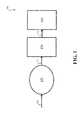
- FIG. 1is a schematic diagram showing an embodiment of an electronic device with power electronics.
- FIG. 2Ais a schematic diagram showing an embodiment of an asynchronous rectifier.
- FIG. 2Bis a schematic diagram showing an embodiment of an asynchronous rectifier with a shorting element.
- FIG. 2Cis a schematic diagram showing an embodiment of an asynchronous rectifier with a feedback loop that includes a comparator.
- FIG. 3Ais a schematic diagram showing an embodiment of an asynchronous rectifier with a synchronizer element.
- FIG. 3Bis a schematic diagram showing an embodiment of a synchronizer element.
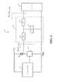
- FIG. 4is a schematic diagram showing an embodiment of an asynchronous rectifier with an impedance matching network.
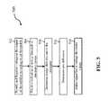
- FIG. 5is a flow chart showing a series of steps for adjusting upper/lower bound voltage thresholds in an asynchronous rectifier.
- FIGS. 6A-Bare schematic diagrams showing an embodiment of a desktop implementation of an asynchronous rectifier.
- FIG. 6Cis a plot showing the effect of device size on coupling.
- FIGS. 7A-Bare plots showing the effect of device size on coupling.
- FIGS. 8A-Bare schematic diagrams showing embodiments of a desktop implementation of an asynchronous rectifier.
- FIG. 8Cis a plot showing the effect of device offset on coupling.
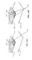
- FIGS. 9A-Care schematic diagrams showing embodiments of a multi-resonator coil device.
- FIG. 10is a schematic diagram showing an embodiment of a resonator with overlapping resonator coils.
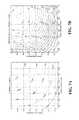
- FIG. 11is a plot showing coupling for a source with a single resonator coil as a function of vertical and horizontal displacement.
- FIGS. 12A-Bare plots showing coupling between a source and a device resonator coil as a function of vertical and horizontal displacement.
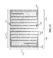
- FIG. 13is a schematic diagram showing an embodiment of a device resonator coil.
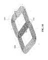
- FIG. 14is a schematic diagram showing an embodiment of a source resonator coil.
- FIG. 15is a schematic diagram showing an embodiment of a desktop with source and device resonator coils.
- FIGS. 16A-Bare schematic diagrams showing embodiments of a device resonator coil with flaps of magnetic material.
- FIGS. 17A-Eare schematic diagrams showing embodiments of resonators.
- FIGS. 18A-Fare schematic diagrams showing different examples of magnetic material configurations.
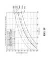
- FIG. 19is a plot showing coil-to-coil efficiency as a function of device resonator size.
- FIG. 20Ais a schematic diagram showing an embodiment of a wireless energy transfer system.
- FIGS. 20B-Care plots showing coil-to-coil efficiency as a function of device position.
- FIGS. 21A-Dare schematic diagrams showing different examples of magnetic material configurations.
- FIG. 22is a plot showing coil-to-coil efficiency as a function of magnetic material width.
- FIGS. 23A-Bare schematic diagrams showing different examples of magnetic material configurations.
- FIG. 24is a plot showing coil-to-coil efficiency as a function of hollow fraction of a magnetic material.
- FIGS. 25A-Care schematic diagrams showing different examples of magnetic material configurations.
- FIG. 26is a schematic diagram showing an embodiment of driving resonators.
- FIG. 27is a schematic diagram showing an embodiment of a source with switchable elements.
- FIG. 28is a schematic diagram showing an embodiment of a source with tunable elements.
- FIG. 29is a schematic diagram showing another embodiment of a source with tunable elements.
- FIG. 30Ais a schematic diagram showing an embodiment of a source with one or more resonators.
- FIG. 30Bis a schematic diagram showing an embodiment of one of the resonators shown in FIG. 30A .
- FIG. 31is a schematic diagram showing an embodiment of an impedance matching network for a source.
- Wireless energy transfer systems described hereinmay be implemented using a wide variety of resonators and resonant objects.
- important considerations for resonator-based power transferinclude resonator quality factor and resonator coupling.
- CMTcoupled mode theory
- coupling coefficients and factorse.g., coupling coefficients and factors
- Q-factorsquality factors
- impedance matchingis provided, for example, in U.S. patent application Ser. No. 13/428,142, published on Jul. 19, 2012 as US 2012/0184338, in U.S. patent application Ser. No. 13/567,893, published on Feb. 7, 2013 as US 2013/0033118, and in U.S. patent application Ser. No. 14/059,094, published on Apr. 24, 2014 as US 2014/0111019. The entire contents of each of these applications are incorporated by reference herein.
- Electronic devicesmay rely on electronic circuits such as rectifiers, AC to DC converters, and other power electronics to condition, monitor, maintain, and/or modify the characteristics of the voltage and/or current used to power the electronic device.
- Power electronicsmay take as input electrical energy from a power source with voltage/current characteristics that may not be compatible with the requirements of the electronic device and modify the voltage and/or current characteristics to meet the requirements of the electronic device.
- the power sourcemay be a mains connection or a battery providing a substantially stable input.
- a power mainsmay provide 120 VAC input which may be rectified and converted to 5 VDC for some electronic devices.
- the power sourcemay be highly variable.
- Power electronics receiving power via highly resonant wireless energy transfermay be required to condition or modify received voltages and/or currents because those voltages or currents may change by 10%, 50%, 100% or more and in some cases may appear as power surges.
- the power electronics used in existing devicesmay not be capable of providing a stable output to an electronic device from such a highly variable power source.
- power electronics circuitsmay include an asynchronous rectifier.
- An asynchronous rectifiermay be part of an efficient and cost effective circuit for monitoring and modifying a variable power input to an electronic device.
- the asynchronous rectifier circuitmay be configured and/or controlled to provide a substantially stable voltage/current output despite changing input voltage and/or current characteristics.
- the asynchronous rectifiermay provide efficient rectification and/or regulation even in converting power wirelessly transmitted using high operating frequencies (e.g., 6.78 MHz) without requiring precise timing for switches, as in traditional synchronous designs.
- the asynchronous rectifiers disclosed hereinmay include a feedback loop that monitors the output of the rectifier and adjusts the operation of one or more components of the rectifier. Adjusting the operation of the one or more components of the rectifier may affect the output characteristics of the rectifier.
- the output of the rectifiermay be configured to maintain a specific voltage and/or current at the output such as 3 VDC, 5 VDC, or more, or others.
- the output of the rectifiermay be adjustable or variable.
- the output of the rectifiermay be set to different operating points such as different output voltages and/or currents.
- the outputmay be set to a first operating point for a first duration of time and to a second operating point for a second duration of time.
- the output of the rectifiermay maintain the first operating point or the second operating point during variations of input power to the rectifier.
- the rectifiermay include a clamping circuit to prevent voltage and/or current surges that may occur at the input of the rectifier to propagate to the output.
- FIG. 1depicts a system 100 which may have variable power input 110 .
- the systemmay include an electronic device 106 with constraints on allowable voltages and/or currents at its power input 112 .
- the power input 110may not be compatible with the constraints of the electronic device.
- the power input 110may be generated from energy that is captured from a magnetic field by a magnetic resonator 102 and transformed into oscillating electrical energy 110 .
- Power electronics 104may be configured to modify the characteristics of the electrical energy 110 received from the resonator 102 to match the requirements of the electronic device 106 .
- the power electronicsmay be configured to rectify and regulate the oscillating electrical energy 110 received from the resonator 102 .
- the oscillating voltage and/or currentmay be rectified to generate a DC voltage or an approximately DC voltage.
- the DC outputmay be further regulated or conditioned to output a desired voltage and/or current and/or multiple voltages/currents (including AC voltages and currents).
- FIG. 2Adepicts an exemplary embodiment of an asynchronous rectifier circuit that may be included in the power electronics circuitry to rectify and regulate an oscillating voltage input from a resonator or another source of oscillating energy 208 .
- the asynchronous rectifier circuitmay include rectifying diode D 1 connected in series with the oscillating energy source 208 .
- a shorting element 212may be arranged in parallel with the oscillating energy source 208 . The shorting element may be controlled by other elements of the asynchronous rectifier to activate and/or short the oscillating energy source 208 thereby bypassing the rectifying diode D 1 .
- the rectifying diode D 1may normally conduct during the positive phase of the oscillating energy source providing a positive (rectified) voltage at the output of the diode D 1 .
- Additional elements 210such as capacitors, inductors, and other elements, may be used to reduce the ripple of the rectified voltage/current and provide a substantially DC voltage (V DC ) to the electronic device.
- the peak voltage at the output of the rectifying diode D 1may depend on the power demands of the electronic device, the peak voltage of the oscillating energy source 208 , and the like. Unless further controlled, the peak voltage at the output of the rectifying diode D 1 may be proportional to the peak voltage of the oscillating energy source 208 and may exceed the voltage constraints of the electronic device receiving energy from the rectifier 200 .
- the peak voltage at the output of the rectifying diode D 1may be controlled by the shorting element 212 .
- the shorting element 212may selectively provide an alternative path for the current from the oscillating energy source 208 such that the current bypasses the rectifying diode D 1 .
- the alternative conducting path through the shorting element 212may be activated based on the voltage at the output of the rectifying diode D 1 or the V DC output from the rectifier to the electronic device.
- the shorting elementmay be selected to have low losses (R ds,on for FET) since during the shorting time period, all transferred power may be dissipated in the resonator and shorting element.
- the switching elementmay include one or more MOSFETs, FETs, bipolar junction transistors (BJTs) or other switch and/or relay and/or transistor types and may be selected based on the performance characteristics and/or cost requirements for an application.
- the shorting elementmay be normally deactivated under normal or acceptable operating conditions. Then the shorting element may be activated when the voltage at the output of the rectifying diode D 1 reaches an upper bound threshold value. When the upper bound threshold value is reached the shorting element 212 may be activated to prevent additional energy from the oscillating energy source 208 from passing through the diode D 1 . If, during this time, the voltage at the output of the rectifying diode decreases due to changing energy demands of the electronic device and/or other circuitry, and reaches a lower bound threshold value, the shorting element may be deactivated allowing more energy to flow through the rectifying diode which may allow the voltage at the output of the rectifying diode D 1 to increase. The cycle of activating and deactivating the shorting element may be controlled by elements of the feedback loop 218 of the asynchronous rectifier to maintain the voltage at the output of the rectifying diode between the upper bound threshold value and lower bound threshold value.
- the shorting elementmay be normally activated and may be deactivated when the output voltage reaches a minimum threshold value and reactivated when the voltage reaches a maximum threshold value.
- the shorting elementmay be activated and deactivated for predetermined amounts of time, periodically, and/or in response to set of triggers such as threshold crossings, temperature measurements, control signals, communication signals and the like.
- FIG. 2Bshows an exemplary embodiment of the asynchronous rectifier circuit with one exemplary embodiment of an implementation of the shorting element 212 .
- the exemplary shorting elementincludes a diode D 2 and a switching element S 1 .
- the diode D 2 and the switching element S 1may be configured in parallel with the oscillating energy source 208 .
- the diode D 2may be configured to provide a ground path to the V DC output when the switching element S 1 is open.
- the switching elementWhen the shorting element is activated (the switch is closed) the switching element may provide for an alternative path for the current from the oscillating energy source 208 .
- the alternative pathmay bypass the rectifying diode D 1 .
- the switching elementmay be a transistors and/or relays.
- the switching elementmay include one or more MOSFETs, FETs, BJTs or other transistor types and may be selected based on the performance characteristics and/or cost requirements for an application.
- Activation and deactivation of the shorting element 212may be controlled via a feedback loop that takes as input the voltage and/or current at the output of the rectifier diode D 1 and/or the output V DC to the electronic device.
- the feedback loopmay include elements or modules or units that provide reference voltage and/or current readings 202 at the output of rectifier diode D 1 and/or other parts of the circuit such as the V DC output.
- the reference readingsmay be used by the switching control unit 204 to determine when to activate/deactivate the shorting element.
- the output of the switching control unit 204may be a signal such as a binary on/off signal to activate/deactivate the shorting element 212 .
- the signalmay be buffered by drivers 206 that provide the correct voltages and switching characteristics for the particular switching elements of the shorting element 212 .
- the feedback loopmay comprise sensing and reference circuitry 202 , a switching control unit 204 , and drivers 206 and may include digital and/or analog circuitry.
- digital logicmay be preferred over analog circuits to define upper/lower bound thresholds and activation/deactivation timers.
- Digital logicsuch as microprocessors, gate arrays, field-programmable gate arrays (FPGAs), and the like may be used to reconfigurably adjust operating points and thresholds.
- analog circuitrymay be preferred.
- Analog circuitrymay provide for faster response times and/or shorter delays between changes in rectified voltage and adjustment of the shorting element.
- a combination of digital and analog circuitrymay be used.
- FIG. 2Cshows an exemplary embodiment of the asynchronous rectifier circuit with one exemplary embodiment of an implementation of the sensing and reference circuitry 202 and switching control unit 204 elements (shown in FIG. 2B ) using analog circuitry.
- the exemplary embodimentincludes a network of resistors, diodes, at least one comparator 214 and a gate driver 216 .
- the network 218 of resistors and the Zener diode V Zmay be used to provide a reference voltage for the comparator 214 .
- the R 1 , R 2 , and R Z resistor values and the Zener voltagemay be used to determine the upper bound voltage for which the comparator 214 may trigger a signal for activating/deactivating switch S 1 .
- the maximum voltage V RECTmay be defined using the values of the resistors and the Zener voltage V Z :
- V RECT , maxV Z ⁇ R HYST + V OUT ⁇ R 1 R 1 ⁇ ( R 2 R 2 + R HYST ) + V Z , where V OUT is the voltage at the output of the comparator 214 .
- the comparator 214triggers the activation of switch S 1 .
- switch S 1Once switch S 1 is activated, the energy from the oscillating energy source 208 will bypass the rectifying diode D 1 .
- the voltage V RECTmay decrease.
- the comparatormay trigger to deactivate switch S 1 .
- the lower bound voltage of V RECT that will cause the comparator 214 to deactivate the switch S 1may be determined by exploiting the hysteresis property of the comparator 214 .
- the lower boundmay be selected by defining the value of the R HYST resistor. The larger the value of the resistor, the greater the hysteresis effect. The greater the hysteresis effect, the larger the difference between the lower bound and upper bound voltages on the V RECT .
- the difference between the lower bound threshold and upper bound thresholdmay result in a ripple in the V RECT voltage.
- the magnitude of the ripplemay be an important factor.
- the magnitude of the ripplemay affect the frequency at which the switch S 1 is turned on/off.
- the switching frequency of S 1may be proportional to the losses of the rectifier.
- the value of the R HYST resistormay be selected to provide acceptable tradeoffs between the magnitude of the ripple and switching losses associated with switch S 1 .
- the ripple at the output V DCmay be reduced by additional components 210 which may include capacitors and/or inductors.
- one or more of the resistorsmay be a variable resistor and may be an electronically adjustable resistor.
- the values of the resistorsmay be adjusted to change the operating point of the rectifier.
- the resistor valuesmay be adjusted to change the maximum voltage, the hysteresis, the magnitude of the ripple and the like.
- the valuesmay be adjusted based on the operating conditions of the electronic device, characteristics of the oscillating energy supply, and the like.
- the value of the R HYST resistormay be adjusted based on the peak voltage of the oscillating energy source.
- the value of R HYSTmay be increased as the peak voltage of the oscillating energy source decreases.
- a voltage reference for the comparatormay be generated by an alternate circuit, DC-to-DC converters, a microprocessor with suitable analog-to-digital and digital-to-analog interfaces, or a battery instead or in addition to the resistor network described herein.
- an electronic devicemay include a battery. The output voltage of the battery may be used as a reference voltage.
- analog circuits shown in FIG. 2Cmay be modified with alternative or complementary circuits and hysteresis methods including Schmitt triggers.
- the functionality of the switching control element 204may be implemented using a microprocessor and/or other digital and analog logic components.
- similar functionality to the comparatormay be implemented using analog to digital converters and a microprocessor.
- Analog to digital convertersmay be used to sample the voltage of the output of the rectifying diode D 1 and digitize the readings. The readings may be monitored and analyzed by a microcontroller. The readings may be monitored to determine if an upper/lower bound voltage threshold has been reached. When a threshold is reached, a control signal for the shorting circuitry may be generated by the microcontroller.
- the microcontroller and/or digital logicmay track the frequency, timing, and/or other characteristics of the rectified voltage and may adjust the upper/lower bound thresholds. For example, when the upper/lower bound threshold values are reached at a frequency that is within a magnitude of the frequency of the oscillating energy source, the microcontroller may adjust the upper and/or lower bound threshold values to decrease the frequency.
- FIG. 3Ashows an exemplary embodiment of an asynchronous rectifier 300 with a synchronizer element 302 that may be used to synchronize the activation/deactivation of the shorting element with the oscillating energy source 208 .
- the synchronizer element 302may synchronize switching of one or more switches of the shorting element with zero voltage and/or zero current conditions of the oscillating energy source.
- the synchronizer element 302may be implemented with analog and/or digital logic and/or circuitry.
- the synchronizer element 302may be part of the switching control element 204 .
- a microprocessor with analog to digital converters, for example,may monitor the oscillating energy input. When the input is at or near the zero value, an enable flag may be set to define when the activation/deactivation signal may be sent to the switching elements of the shorting element 212 .
- FIG. 3Bshows one exemplary embodiment of the synchronizer element 302 comprising a comparator 306 and an AND gate 304 .
- the control output (ASYNC signal) of the switching control 204may be gated by the AND gate 304 until another signal to the AND gate 304 indicates a zero voltage/current condition.
- the signal indicating a zero voltage/current conditionmay be generated by the comparator 306 .
- the comparatormay take as input (AC signal) the oscillating energy source. The comparator may output a high signal when the voltage on the AC input is low thereby allowing the high ASYNC signal to propagate. Similar designs may be used for deactivation of the shorting element switches.
- FIGS. 2A-2C and 3A-3Brelate to exemplary embodiments based on half wave rectifier designs. It is to be understood that the asynchronous rectifier may also be based on a full wave rectifier. Control and shorting elements may be used to bypass rectifying diodes on both positive and negative portions of the voltage cycle of the oscillating source.
- FIGS. 2A-2C and 3A-3Brelate to exemplary embodiments of asynchronous rectifiers capable of regulating an output voltage.
- the asynchronous rectifiersmay also regulate an output current. Currents at the output of the rectifier may be measured and the shorting circuit activated/deactivated based on upper/lower bound current thresholds.
- an asynchronous rectifiermay be directly coupled to an oscillating energy source.
- the oscillating energy sourcemay include a magnetic resonator that is part of a wireless energy transfer system.
- the magnetic resonatormay receive energy from another source via oscillating magnetic fields.
- the resonatormay be coupled to the asynchronous rectifier via a matching network.
- the matching network connecting the resonator and the asynchronous rectifiermay be configured with the operation of the rectifier in mind.
- the asynchronous rectifiermay have different impedance characteristics depending on the activation/deactivation of the shorting element. Changes in the impedance of the asynchronous rectifier may affect the performance of the resonator and affect the efficiency of wireless energy transfer.
- FIG. 4shows an exemplary embodiment of an asynchronous rectifier coupled to a resonator 410 via an impedance matching network 402 .
- the impedance matching networkmay be configured to improve or optimize the efficiency of energy transfer to resonator 410 from a wireless magnetic field source.
- the load impedance of the asynchronous rectifiermay be significantly lower when the shorting element 212 is activated compared to when the shorting element is deactivated.
- the load impedance R Lmay include the impedance of the electronic device that receives energy from the asynchronous rectifier.
- the load impedance R L,SHORTmay be significantly lower.
- the lower load impedancemay decrease the energy transfer efficiency during the time when the shorting element is activated.
- the impedance matching networkmay be configured such that when the shorting element is activated, the impedance R IN,SHORT as seen from resonator 410 through the impedance matching network is large.
- the impedance matching network 402may be configured such that when the shorting element is deactivated, the impedance R IN as seen from resonator 410 through the impedance matching network is similar to the load impedance R L .
- impedance matching network 402may be configured to minimize losses when the shorting element is activated. When the shorting element is activated no power is going to the electronic device at the V DC output, and the effective efficiency during this time may be zero.
- the elements of the impedance network X 1 406 and X 3 404may provide an inductance and may include components such as inductors.
- Element X 2 408may provide a capacitance and may include components such as capacitors.
- the elements of the impedance matching network 402may be selected to maximize the impedance R IN,SHORT , via the following equation:
- R INX 2 2 ⁇ R L R L 2 + ( X 2 + X 3 ) 2 .
- FIG. 5illustrates a set of steps that are part of a method for adjusting upper/lower bound voltage thresholds in the feedback loop of the asynchronous rectifier.
- the upper/lower bound voltage thresholds that are used trigger the activation/deactivation of the shorting elementmay be adjusted based on electrical characteristics of the electronic device connected to V DC , electrical characteristics of the resonator, and/or magnetic field characteristics.
- the asynchronous rectifiermay activate/deactivate the shorting element based on the upper/lower voltage thresholds.
- the feedback loopmay activate the shorting element and deactivate the shorting element when the lower bound threshold is reached.
- the feedback loopmay receive an indication of the energy demands of the electronic device to which the asynchronous rectifier is connected at V DC .
- a communication channel from the electronic devicemay indicate the energy demands of the device based on processor demands, user interaction, and/or the like.
- the energy demands of the electronic devicemay be estimated based on historical data of the energy demands based on time of the day, for example.
- the power consumptionmay be determined by measuring the current at the input of the electronic device.
- the energy delivery rate to the resonatormay be determined. The energy delivery rate may be determined by the peak voltages and/or currents on the resonator.
- an additional resonator or sensormay be used to measure magnetic field strength near the resonator.
- the field strengthmay be indicative of the energy delivered to the resonator.
- the difference between the available energy transfer rate at the resonator and the energy transfer rate demanded by the electronic devicemay be determined and in step 510 , the difference in energy (e.g., the difference in energy transfer rate) may be used to adjust the upper/lower bound voltage thresholds.
- a large difference between the energy demands of the electronic device and the energy delivered to the resonatormay be used to increase the upper and/or decrease the lower voltage thresholds (i.e. increase the ripple at the output of the asynchronous rectifier).
- the changes in the thresholdsmay be configured to reduce the frequency of activation/deactivation of the shorting elements of the asynchronous rectifier.
- a small difference between the energy demand of the electronic device and the energy delivered to the resonatormay be used to decrease the upper and/or increase the lower voltage thresholds.
- the thresholdsmay be adjusted to ensure the frequency of activation/deactivation of the shorting element is at least five or ten times or slower than the frequency of the oscillating energy at the input to the rectifier.
- the asynchronous rectifier designs and methods described hereinmay be applied to wireless energy transfer in a variety of applications, including desktop applications.
- a wireless energy transfer system for desktop applicationsmay power or charge a plurality of electronic devices at the same time.
- the systemmay include one or more wireless energy sources to transfer energy to one or more wireless energy receivers or devices. Energy may be transferred to devices positioned on a desk, table, shelf, lab bench, or other surface. Electronic devices such as laptops, smartphones, tablets, computer peripherals, and the like positioned on or near the surface may wirelessly receive energy from an energy source below, near, or on top of the surface.
- a sourcemay include one or more magnetic resonators that, during operation, couple and transmit power via an oscillating magnetic field to one or more electronic device magnetic resonators. The power transmitted may be sufficient and/or efficient enough to directly power or recharge electronic devices.
- Wireless power transfer on desktops, tabletops, and in similar environmentscan be challenging using conventional methods due to the large combination of arrangements or use cases that may result.
- a laptop, mouse, phone, and monitormay need to be powered or charged at the same time.
- the physical arrangement of the electronics on a wirelessly powered desktop or areamay determine the efficiency of power transfer.
- the position, materials, distance of one devicemay affect the energy delivery to all the devices.
- the position of one devicemay change the power input to one or more devices. As devices are repositioned, their coupling with the source may change, affecting the efficiency and power input to the other devices.
- the asynchronous rectifier described hereinmay be used to rectify and regulate the electrical energy received by the magnetic resonators of the electronic devices in a wireless power transfer system.
- the asynchronous rectifiermay be configured to provide constant voltage/current to the electronic devices even when the power input to the resonators is changing and may have a wide variance.
- the power input variance to the electronic devicescan be reduced. Reduced power variance may result in more efficient energy transfer and in less energy lost in regulating and rectifying components.
- the power input variations in a desktop wireless energy transfer systemmay be reduced through appropriate resonator designs.
- the design of resonatorsmay take into account lossy environments, varying proximity of one or more devices to one or more sources, human interfacing including user safety, mobility of the system or the system's parts, and similar criteria.
- resonator designmay vary according to the number of devices requiring power as well as the types of devices.
- resonator designsmay balance positional tolerance (maintaining a level of efficiency over varying positions) with achieving high efficiency at a single position or orientation.
- one or more tunable capacitorsmay be part of a resonator and/or an impedance matching network.
- One or more tunable capacitorsmay be part of a source, a device, and/or a repeater in a wireless energy transfer system.
- Capacitancemay be tuned, for example, in response to varying proximity of one or more devices to one or more sources, lossy environments, human interfacing including user safety, and/or mobility of the system or the system's parts.
- a capacitance in a sourcemay be tuned in response to the positioning of a device relative to the source.
- a capacitance in a sourcemay be tuned in response to a lossy object, such as a metallic object, being brought near the wireless energy transfer system.
- a tunable capacitormay include a bank of capacitors, where the capacitance of the bank is controlled by a switch.
- a relaymay be used to tune the capacitance.
- a switch or relay or similar componentmay be activated in response to a current or voltage measurement and may be controlled via a microcontroller. For example, current measurements may be taken at two points of the source-side impedance matching circuitry. In exemplary embodiments, the phase difference between the two current measurements may serve as a control signal for a relay (or switch or comparable component).
- the number of capacitors in a bankmay be determined, for example, by cost, spatial constraints, power requirements, and/or degree of tunability.
- a tunable capacitormay be an augmentation to a fixed capacitance and may serve as a “fine-tuning” mechanism for tuning purposes.
- wireless desktop configurationsmay include a single device resonator in each device and a single source resonator.
- FIG. 6AA desktop configuration with one source resonator coil 602 and one device resonator coil 606 attached to a device 604 is shown in FIG. 6A .
- the coupling k between the source coil 602 and device coil 606may be affected by the relative size of the source coil 602 and device coil 606 .
- the couplingmay affect the energy transfer parameters and may affect the energy transfer efficiency and variance of changes in power delivery.
- the coupling between the source and the devicemay be increased by increasing the size of the device resonator.
- coupling kmay increase with an increase in device resonator size.
- FIG. 6Bshows an exemplary embodiment of a device resonator with increased size, relative to FIG. 6A .
- FIG. 6Cshows how coupling k changes as a function of the size of the device resonator coil relative to the size of the resonator coil for the configuration shown in FIGS. 6A-6B with a 500 mm by 350 mm source resonator coil.
- the coupling k between the source resonator coil 602 and the device resonator coil 606may increase as the size of the square shaped device resonator coil increases.
- FIGS. 7A-7Bshow calculations of coupling k and energy transfer efficiency as functions of device length and width for the configuration shown in FIG. 6A .
- Wireless coupling and transfer efficiencyincrease as the size of the device resonator coil approaches the size of the source resonator coil.
- the coupling k between the source coil 602 and device coil 606may be affected by relative position of the device coil 606 with respect to the device 604 .
- Device resonator coil 606may be positioned in the middle of the device 604 as shown in FIG. 8A .
- the device resonator coil 606may be positioned in various parts of an electronic device 604 .
- FIG. 8Bshows an exemplary embodiment of a device resonator coil 606 positioned in the corner of an electronic device 604 .
- FIG. 8Cshows the coupling k between the device resonator coil 606 and the source resonator coil 602 as a function of the position of the resonator coil 606 with respect to the device 604 .
- the couplingincreases with greater offset between the centers of the device resonator coil and the device.
- the offset parameteris determined by the position of the center of the device resonator coil 606 relative to the center of the device 604 .
- an offset parameter of 0represents no offset between the center of the device 604 and resonator coil 606
- an offset parameter of 1represents a maximum offset as shown when the resonator is positioned in the corner of the device 604 ( FIG. 8B ).
- Wireless desktop configurationsmay include devices with more than one device resonator coil. Multiple device resonator coils may be positioned on or around a device. Multiple resonator coils may be selectively used and/or used in combination depending on their coupling, orientation, and/or position relative to the source resonator coil. In exemplary embodiments, devices with multiple device resonator coils may improve coupling with the source resonator coil and reduce or eliminate poor coupling due to null regions under various use-case scenarios and positions/orientations.
- FIG. 9AAn exemplary desktop configuration with one source resonator coil 902 and two device resonator coils 904 , 906 is shown in FIG. 9A .
- the device resonator coils 904 , 906may couple to a source resonator coil 902 even when positioned over a null region of the source resonator coil 902 , as shown in FIG. 9B .
- the outputs of multiple device resonatorsmay be electronically combined to deliver power to the device.
- FIG. 9Cshows a further exemplary embodiment in which a device includes four device resonator coils 910 , 912 , 914 , 916 .
- a devicemay include configurations with one resonator coil and/or configurations with two or more resonator coils.
- the multiple resonator coilsmay be positioned side by side to cover an area.
- adjacent resonator coilsmay be positioned to overlap one another.
- two source resonator coilsmay be placed such that coupling between them is minimized, i.e. they are in each other's dead spots.
- the source resonator coilsmay be driven 90 degrees out of phase or driven at different times or with different phases with respect to each other to achieve spatially uniform coupling or more uniform magnetic field density between the source resonators and the device.
- FIG. 10shows an exemplary embodiment of two overlapped source resonator coils 1004 , 1006 .
- the resonator coils 1004 , 1006overlap over a distance 1002 that spans a portion of their coil windings.
- This resonator coil arrangementmay eliminate or reduce null spots over the area enclosed by the combined resonator coils of the source, relative to a configuration in which coils 1004 and 1006 do not overlap.
- Such an arrangementmay provide for a uniform or near-uniform coupling over the area spanned or enclosed by the two resonator coils to other magnetic resonators of a wireless power transfer system.
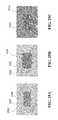
- FIG. 11shows simulated coupling coefficient magnitudes between a source and device, each with a single resonator.
- the graphshows the lack of uniformity in the coupling coefficient as the device is horizontally displaced from the center of the source coil (labeled “0” on the x-axis) to the edge of the source coil, decreasing from a coupling coefficient value
- FIG. 12Ashows simulated coupling coefficient values for a source and device, the source having two overlapped resonators similar to the resonators shown in FIG. 10 when the two resonators are driven in-phase and at the same drive frequency. In this exemplary embodiment, the coupling values are less uniform in some regions, such as in between the two coil centers.
- FIG. 12Bshows simulated coupling values for a source and device, the source having two overlapped resonators as shown in FIG. 10 and driven with the same frequency but 90 degrees out-of-phase.
- the coupling valuesare more uniform over horizontal displacements of the device over the source. Note there are no null spots in the coupling coefficient between the source and the device using the arrangement of source coil position and drive signals shown in FIG. 12B .
- Design parameters of a device resonator coilmay include size, shape, thickness, number of turns, density of the turns, span size, number of coils, and the like.
- Resonators for use in desktop applicationscan, in some embodiments, include two sets of loops formed by one contiguous conductor.
- the two sets of loopscan be positioned side by side and may spiral inwards in the same direction.
- Each loop in each set of loopscan be positioned substantially off-center from other loops in the set, each inner loop of each set of conductor loops can be positioned off-center from the outer loop away from the second set of loops.
- FIG. 13shows a resonator coil with two sets of loops 1318 , 1308 formed by one contiguous conductor with both sets of loops spiraling inwards in a counterclockwise direction.
- Each set of loops 1318 , 1308includes five loops of an electrical conductor that spiral inwards.
- Each loop in each set of loops 1318 , 1308may not be concentric with the other loops in each set.
- each conductor loop of each set of loopsmay be configured such that they are shifted off-center from the outer loop.
- the loops of the set of loops of 1318are not concentric, but offset such that the loops are off-center away from the center of the set of loops 1308 . Due to the off-center arrangement of the conductor coils, the spacing of loops relative to each other may be asymmetric. The spacing between adjacent loops may be larger on the side of the loops facing the other set of loops and smaller on the outside of the set of loops. For example, in the exemplary embodiment shown in FIG. 13 , the spacing 1304 between the conductor of adjacent loops is larger on the side facing the other set of loops than the spacing on the outside of the conductor coil 1302 , 1310 .
- the width of the conductor forming the loops of each set of loopsmay be non-uniform and may change depending on the location of the conductor in each loop, and the like.
- the width of the conductor forming the loopsmay be proportional to the spacing between the conductors of adjacent loops. The larger the spacing (e.g., where the loops are spaced by a distance 1304 ), the larger the width of the conductor. In areas where the spacing between the conductors is smaller (e.g., where the loops are spaced by a distance 1302 ), the width of the conductor traces may be relatively smaller.
- the resonator coilmay be “anti-symmetric” along its length 1314 . That is, the left side of the resonator coil may be similar to the right side of the coil but rotated 180 degrees.
- the span of the coilmay be similar along the outermost edges, but more spread out in the center.
- the thickness of the coilmay vary along its length; traces along the outer edges can be thinner, while traces in the middle region of the coil can be thicker.
- the density of the coil traces at the outer edge of the resonator coilcan vary compared to the inner area of the resonator coil, to allow for generation of a more uniform magnetic field over the overall area of the resonator coil.
- the resonator coil loopsmay have a rectangular shape as shown in FIG. 13 . More generally, coil loops with oval, circular, triangular, and other shapes may also be used. In exemplary embodiments the two sets of loops may have different shapes. One set of loops may be rectangular while the other circular, for example. In exemplary embodiments, one sets of loops may have different dimensions and/or different number of loops than the other set.
- FIG. 14shows an exemplary embodiment of a resonator coil design that may be used for a source resonator coil in various applications, including desktop applications.
- the resonator coil 1402includes more than one electrical conductor shaped to form one or more coils.
- each of the conductors in the resonator coilforms an “S” shape.
- the conductorsare nested, forming a set of nested “S” shaped conductors.
- Each conductoris shaped or curved in one direction (e.g. clockwise) to form one loop and then shaped or curved in an opposite direction (e.g. counterclockwise) to form a second loop, forming an “S” shape.
- the conductorsmay be shaped to form loops that are substantially rectangular, circular, oval, or other shapes.
- FIG. 14shows an exemplary embodiment with five conductors forming five offset “S” shapes.
- the conductors 1404 , 1406 , 1408 , 1410 , 1412are configured so that they are offset from one another.
- additional conductor traces 1414 , 1416 , 1418 , 1420 , 1422may optionally be used to close the ends of the “S” shaped conductors.
- the additional conductor traces 1414 , 1416 , 1418 , 1420 , 1422may be coupled to amplifiers and/or impedance matching networks.
- the ends of the conductorsmay be coupled to amplifiers and the conductors may be configured to be driven independently, in groups (e.g., in series or in parallel or a combination of series and parallel), and/or all at once.
- the resonator coils shown in FIG. 14may be implemented as a printed circuit coil with printed or etched conductor traces on a substrate such as a circuit board.
- the additional conductor traces 1414 , 1416 , 1418 , 1420 , 1422may be formed or printed on a different conductor layer than the “S” shaped conductors 1404 , 1406 , 1408 , 1410 , 1412 .
- FIG. 15shows an exemplary embodiment with an “S” shaped coil used for a source resonator coil 1502 and an “S” shaped coil used for a device resonator coil 1504 .
- metallic materials with good electrical conductivitysuch as aluminum, copper, gold, and the like may be used to shield a resonator coil.
- Sheets of an electrical conductor materialmay be placed under, near, or over a resonator coil to shape and/or minimize loss of the magnetic field near lossy materials.
- the size of the sheet of the conductormay be larger than the size of the resonator coils.
- the sheets of conductormay be positioned between a device and a device resonator coil.
- magnetic materialsuch as ferrite may be used to shield the coil from metallic components of devices and sources, and electronics or other lossy materials. Sheets, tiles, pieces, and other fragments of magnetic material may be positioned between the resonator coils and lossy materials.
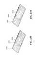
- the magnetic materialmay be shaped or configured with flaps or edges that overhang and/or wrap around the device coil.
- FIG. 16Ashows an exemplary embodiment of a resonator coil with a flap 1608 (shown as a darker material) around one edge of the device 1602 .
- FIG. 16Bshows an exemplary embodiment of a resonator coil with two flaps 1608 around two edges of the device 1602 . The addition of two flaps formed of magnetic material has been shown to provide over 40% improvement in the coupling coefficient over a configuration with no flaps.
- FIGS. 17A-Eshow various exemplary embodiments of a device resonator coil and magnetic material that improve coil-to-coil coupling efficiency.
- FIG. 17 Ashows a first exemplary embodiment in which the resonator coil 1704 is placed near the edge of the apparatus 1702 ;
- FIG. 17Bshows another exemplary embodiment in which magnetic material 1706 is used as an overhang;
- FIG. 17Cshows another exemplary embodiment in which magnetic material 1708 forms both a bridge (between the overhang material and the resonator coil which is sitting on top of a layer of magnetic materials) and an overhang;
- FIG. 17 Ashows a first exemplary embodiment in which the resonator coil 1704 is placed near the edge of the apparatus 1702 ;
- FIG. 17Bshows another exemplary embodiment in which magnetic material 1706 is used as an overhang;
- FIG. 17Cshows another exemplary embodiment in which magnetic material 1708 forms both a bridge (between the overhang material and the resonator coil which is sitting on top of a layer of magnetic
- FIG. 17Dshows another exemplary embodiment in which the resonator coil 1704 abuts the magnetic material overhang 1710 ;
- FIG. 17Eshows another exemplary embodiment in which the resonator coil 1704 is wrapped over the corner of the apparatus.
- the coil-to-coil efficiency in the exemplary embodiments shown in FIGS. 17D-Emay be greater than those shown in FIGS. 17A-C . Without wishing to be bound by theory, it is believed that this may be due to the positioning of the resonator 1704 , which is nearer the edge of the apparatus 1702 in FIGS. 17D-17E .
- FIG. 18Ashows an exemplary embodiment of a device resonator with magnetic material placed below the resonator coil 1808 , between the resonator coil 1808 and the device 1802 .
- FIG. 18Bshows a variation to that exemplary embodiment where the magnetic material 1804 has been extended out from beneath the coil 1808 and positioned to one side of the device 1802 as a single “bridge” to the edge of the device 1802 .
- FIG. 18Cshows a further exemplary embodiment where the magnetic material is arranged as a dual “bridge” 1810 that is constructed to cover an area that runs along the length of the device 1802 .
- FIG. 18Dshows an exemplary embodiment of a device resonator with magnetic material placed below the resonator coil 1808 , between the resonator coil 1808 and the device 1802 .
- the length 1812 of the resonator coil 1808has been increased as compared to the resonator coil 1808 shown in FIG. 18A .
- FIG. 18Eshows an exemplary resonator embodiment that includes magnetic material shaped as a single “bridge” 1804 and an increased resonator coil length 1812 .
- FIG. 18Fshows an exemplary resonator embodiment featuring magnetic material shaped as a dual “bridge” 1810 and an increased resonator coil length 1812 .
- FIG. 19shows the calculated coil-to-coil coupling efficiency values in a wireless energy transfer system that includes a source and a device similar to the exemplary embodiments shown in FIGS. 18A-F .
- the source resonatorhas dimensions of 273 mm by 160 mm whereas the device resonator has a fixed width of 86 mm and variable length between 50 mm-200 mm.
- the coil-to-coil efficiency valuesare plotted as a function of device resonator coil length 1812 . As resonator coil length 1812 is increased from 50 mm (as shown in FIGS. 18A-C ) to 200 mm (as shown in FIGS. 18D-F ), efficiency values increase.
- Coil-to-coil coupling efficiency valuesare plotted for each magnetic material configuration shown in FIGS. 18A-C and FIGS. 18D-F .
- the predicted coupling efficienciesare shown by traces 1912 and 1908 respectively.
- the arrangement shown in FIG. 18B and FIG. 18Ei.e., single bridge, 0.25 mm thick ferrite and 0.5 mm thick ferrite results are shown in traces 1910 and 1904 respectively.
- FIG. 18C and FIG. 18Fi.e. dual bridge, 0.25 mm thick ferrite and 0.5 mm thick ferrite are shown in traces 1906 and 1902 respectively.
- FIG. 20Ashows a schematic diagram of an embodiment of a wireless energy transfer system that includes a source resonator 2002 and a device resonator 2004 in a Cartesian (X-Y) coordinate system.
- FIGS. 20B-Cshow coil-to-coil efficiency values for device resonator 2004 as a function of position relative to the center of source resonator 2002 . Note that for this exemplary embodiment the device resonator 2004 has fixed dimensions of 200 mm by 86 mm while the source resonator 2002 has fixed dimensions of 273 mm by 160 mm.
- FIG. 20Bshows coil-to-coil efficiencies as a function of position along the X-axis for exemplary magnetic material configurations shown in FIGS. 18A-C . For the arrangement shown in FIG.
- a source with dual bridge and overhang or “lip”produces the best coil-to-coil efficiency for a span of positions in the X-axis.
- FIG. 20Cshows coil-to-coil efficiencies as a function of position in the Y-axis for the exemplary magnetic material configurations shown in FIGS. 18A-C .
- the predicted coupling efficienciesare shown by traces 2018 and 2020 respectively.
- the predicted coupling efficienciesare shown by traces 2022 and 2024 respectively.
- the predicted coupling efficienciesare shown by traces 2026 and 2028 respectively.
- a source with dual bridge and overhang or “lip”produces the best coil-to-coil efficiency for a span of positions in the Y-axis.
- the width of a bridge made of magnetic materialmay also affect efficiency of energy transfer.
- FIGS. 21A-Bshow examples of devices 2102 with device resonators 2104 that include a thin bridge of magnetic material, single 2106 and dual 2112 , respectively.
- FIGS. 21C-Dshow device resonators 2104 with a thicker bridge of magnetic material, single 2110 and dual 2114 , respectively.
- FIG. 22shows the coil-to-coil coupling efficiency values of the exemplary embodiments shown in FIGS. 21A-21D .
- FIG. 22also shows the coil-to-coil coupling efficiency values of a “baseline” measurement of a device resonator with magnetic material that has no bridge or overhang configuration.
- a device resonator with magnetic material of 0.25 mm and 0.5 mm thicknessefficiencies are shown in traces 2202 and 2204 respectively.
- traces 2202 and 2204For the arrangement shown in FIG. 21A and FIG. 21C , i.e., a single bridge of 0.25 mm thick ferrite and 0.5 mm thick ferrite, efficiencies are shown in traces 2206 and 2208 respectively.
- FIG. 21B and FIG. 21Di.e., a dual bridge of 0.25 mm thick ferrite and 0.5 mm thick ferrite, efficiencies are shown in traces 2210 and 2212 respectively.
- the shape of magnetic materialmay be varied to realize certain performance and/or system parameters such as energy transfer efficiency, resonator weight, resonator cost, and the like.
- FIGS. 23A-Bshow two exemplary resonator embodiments in which the weight has been reduced by using magnetic material structures 2304 that have been hollowed out near their centers.
- 10% of a 75 by 50 by 0.25 mm 3 volume 2306 of magnetic material 2304has been removed from near the center of the slab of magnetic material used on a device resonator 2302 .
- FIG. 23A10% of a 75 by 50 by 0.25 mm 3 volume 2306 of magnetic material 2304 has been removed from near the center of the slab of magnetic material used on a device resonator 2302 .
- FIG. 24shows the coil-to-coil coupling efficiency of the device resonator as a function of the fraction of the magnetic material slab that has been hollowed out. As this fraction increases, the coil-to-coil efficiency decreases.
- the efficiency calculations shownare for a device with magnetic material that does not cover the width of the device (plot 2402 ) and a device with magnetic material that covers the width of the device and has overhang (plot 2404 ). There is a marked increase in the coil-to-coil efficiency for a device with magnetic material that covers the width of the device and has an overhang, as shown in FIGS. 23A-B .
- highly conducting and/or metallic materialssuch as aluminum and/or copper may be used for shielding a resonator to attain high efficiency and coupling and to preserve the high quality factor of the magnetic resonators.
- these materialsmay be placed under, near, or over a resonator coil to shape and minimize loss of the magnetic field near lossy materials, such as other metals.
- FIGS. 25A-Cshow three exemplary embodiments in which differently sized highly conducting materials 2506 , 2508 , 2510 are used to shield device coil 2504 from, for example, the chassis of a device such as a laptop 2502 .
- the chassis of a devicemay be lossy to magnetic fields and may affect wireless power transfer efficiency.
- the material used to shield the device coilmay be copper, aluminum, and the like. Increasing the size of the shield may decrease magnetic field losses.
- one or more amplifiersmay be used to drive one or more source resonators.
- the use of more than one amplifiermay be advantageous for actively tuning resonator circuits and detecting resonator coils that are being used for power transfer.
- An additional advantage of using more than one amplifiermay be to provide protection against the back driving of current.
- FIG. 26shows an exemplary embodiment of a circuit where each resonator is driven by its own amplifier. As shown, there are N amplifiers 2602 to drive N resonators 2604 .
- more than one amplifiercan drive each resonator. For example, N ⁇ M amplifiers may be used to drive N resonators, where M is a scaling integer such as 2, resulting in 2 amplifiers driving each resonator. In yet another exemplary embodiment, each amplifier may drive more than one resonator.
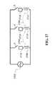
- FIG. 27shows an exemplary embodiment of a single amplifier 2702 driving a circuit that includes one or more resonators, each including an inductor 2708 , 2710 , 2712 and an element 2714 , 2716 , 2718 such as a capacitor, inductor, resistor, and the like, that may be switched in or out. There may be mutual inductance 2704 , 2706 between resonators. Similarly, one or more resonators may be switched in or out of the circuit using switches “S”.
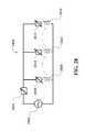
- FIG. 28shows an exemplary embodiment of wireless power source 2800 that includes a single amplifier 2802 driving one or more resonators in parallel.
- the resonatorsinclude circuit elements 2804 , 2810 , 2814 , 2816 which are tunable and may be inductors, capacitors, resistors, and the like, as well as inductors 2808 , 2812 , 2816 .
- the source 2800can be “automatically” tuned by allowing certain resonators to preferentially draw current from amplifier 2802 .
- “automatic tuning”can occur when a device is positioned on or near a source that has inductors 2808 , 2812 , 2816 in parallel.
- a devicemay be able to charge by “detuning” the inductor that it is closer to.
- inductors 2808 , 2812 , 2816may be tuned to a particular impedance and the device detunes the inductor it rests on or near.
- the devicemay be able to charge by “tuning” the inductor that it is closer to.
- the inductors 2808 , 2812 , 2816can each be driven by a power source (e.g., amplifier 2802 ). These inductors have impedances Z 1 , Z 2 , and Z 3 , respectively, and can be considered “detuned” in the absence of a device placed in proximity to the inductors.
- a deviceis positioned on or near one of the inductors, mutual coupling between the device and the inductor can modify the impedance of the source resonator represented by the inductor, which “tunes” the inductor.
- inductor 28suppose a device is placed on or near inductor 2812 with impedance Z 2 . Coupling between the device and inductor 2812 can change the impedance Z 2 of inductor 2812 , such that it “tunes” the impedance value Z 2 of that particular inductor. In other words, the presence of the device can decrease the impedance Z 2 at inductor 2812 , such that current from amplifier 2802 is preferentially drawn to inductor 2812 , allowing for wireless power transfer to preferentially occur between the resonator represented by inductor 2812 and the device.
- the impedances Z 1 and Z 3 of inductors 2808 and 2816are higher than the impedance Z 2 of inductor 2812 , so that the amount of power transfer between the resonators represented by inductors 2808 and 2816 and the device is significantly less, and in some embodiments, is even zero.
- impedance characteristics of source 2800are controlled through appropriate selection of various parameters of resonator (e.g., inductor) coils, including the size, shape, thickness, number of turns, and density of turns.
- resonatore.g., inductor
- inductors 2808 , 2812 , and 2816are designed so that, in the absence of a device positioned in proximity to any of the inductors, the impedances Z 1 , Z 2 , and Z 3 vary by 10% or less (e.g., 5% or less, 1% or less).
- inductors 2808 , 2812 , and 2816are designed so that when a device is positioned on top of, or near to, a particular one of the inductors, the impedance of that inductor is significantly reduced, thereby causing wireless power transfer between the resonator represented by that inductor and the device, in strong preference to wireless power transfer from the resonators represented by the other inductors.
- the impedance Z 2is reduced so that the impedances Z 1 and Z 3 of inductors 2808 and 2816 are each larger than Z 2 by a factor of 2 or more (e.g., by a factor of 5 or more, by a factor of 10 or more).
- the source shown in FIG. 28can have certain advantages from a cost standpoint compared to the source shown in FIG. 27 , as there are no potentially costly switches used for operation. This may also be preferable from a control standpoint because the source may rely on automatic tuning to achieve higher efficiency at the resonator being activated by a device. In exemplary embodiments, this tuning scheme may be referred to as a “fixed” scheme, as the multiple source resonators are wired to the circuit.
- FIG. 29shows an exemplary embodiment of an amplifier 2902 driving a circuit that includes source resonators with tunable inductors 2904 , 2906 , 2908 and elements 2910 , 2912 , 2914 such as capacitors, inductors, resistors, and the like.
- the inductance of tunable inductors 2904 , 2906 , 2908may be changed to tune or detune the one or more resonators, e.g., by a controller or control circuit (not shown in FIG. 29 ), as discussed previously.
- this tuning schememay also be referred to as a “fixed” scheme, as the multiple source resonators are wired to the circuit.
- FIGS. 30A-Bshow exemplary embodiments of wireless power sources where the source resonators and/or tuning components are not permanently fixed or wired to an amplifier.
- an amplifier 3002drives an inductor 3004 which is inductively coupled (as shown by arrows 3006 ) to multiple separate resonators 3008 .
- An example of resonator 3008is shown in FIG. 30B .
- the resonatorincludes an inductor 3014 and additional elements 3016 , 3018 , 3020 which may be connected in series and/or parallel with inductor 3014 .
- These additional elements 3016 , 3018 , 3020may be capacitors, inductors, resistors, switches, diodes, and the like.
- One advantage to this sourceis the positional freedom of resonators 3008 .
- FIG. 31shows one or more amplifiers 3102 connected to a matching network 3106 which may be connected to one or more source resonators 3104 .
- the matching network 3106may be used to provide impedance matching for one, some, or all of the source resonators 3104 .
- any of the amplifiers 3102may be switched to drive one, some, or all of the resonators 3104 .
- amplifiers 3102 , matching network 3106 , and source resonators 3104can be controlled by a microcontroller (not shown) to determine which amplifiers drive which resonators.
- the distance, distribution, number of electronic devices that can be powered or chargedmay be enhanced by the use of passive, intermediate magnetic resonator repeaters.
- active magnetic resonator repeatersmay be used to enhance, facilitate, or control the distance, distribution, or number of electronic devices that can be powered or charged.
- desktop wireless power transfer applicationse.g., power transfer to electronic devices such as laptops, smartphones, and other mobile electronic devices that are commonly placed on desktops, tabletops, and other user work surfaces.
- devices that can receive power using the devices, components, and methods disclosed hereincan include a wide range of electrical devices, and are not limited to those devices described for illustrative purposes herein.
- any portable electronic devicesuch as a cell phone, keyboard, mouse, radio, camera, mobile handset, headset, watch, headphones, dongles, multifunction cards, food and drink accessories, and the like, and any workspace electronic devices such as printers, clocks, lamps, headphones, external drives, projectors, digital photo frames, additional displays, and the like, can receive power wirelessly using the devices, components, and methods disclosed herein.
- circuit componentssuch as capacitors, inductors, resistors, diodes, and switches are referred to as circuit “components” or “elements.”
- the disclosurealso refers to series and parallel combinations of these components or elements as elements, networks, topologies, circuits, and the like. Further, combinations of capacitors, diodes, transistors, and/or switches are described. More generally, however, where a single component or a specific network of components is described herein, it should be understood that alternative embodiments may include networks for elements, alternative networks, and/or the like.
Landscapes
- Engineering & Computer Science (AREA)
- Power Engineering (AREA)
- Computer Networks & Wireless Communication (AREA)
- Signal Processing (AREA)
- Physics & Mathematics (AREA)
- Electromagnetism (AREA)
- Dc-Dc Converters (AREA)
- Charge And Discharge Circuits For Batteries Or The Like (AREA)
Abstract
Description
where VOUTis the voltage at the output of the
while satisfying
Claims (23)
Priority Applications (4)
| Application Number | Priority Date | Filing Date | Title |
|---|---|---|---|
| US14/745,041US9954375B2 (en) | 2014-06-20 | 2015-06-19 | Wireless power transfer systems for surfaces |
| US15/956,791US20180241220A1 (en) | 2014-06-20 | 2018-04-19 | Wireless power transfer systems for surfaces |
| US15/956,797US10923921B2 (en) | 2014-06-20 | 2018-04-19 | Wireless power transfer systems for surfaces |
| US17/174,820US11637458B2 (en) | 2014-06-20 | 2021-02-12 | Wireless power transfer systems for surfaces |
Applications Claiming Priority (2)
| Application Number | Priority Date | Filing Date | Title |
|---|---|---|---|
| US201462015078P | 2014-06-20 | 2014-06-20 | |
| US14/745,041US9954375B2 (en) | 2014-06-20 | 2015-06-19 | Wireless power transfer systems for surfaces |
Related Child Applications (2)
| Application Number | Title | Priority Date | Filing Date |
|---|---|---|---|
| US15/956,791ContinuationUS20180241220A1 (en) | 2014-06-20 | 2018-04-19 | Wireless power transfer systems for surfaces |
| US15/956,797ContinuationUS10923921B2 (en) | 2014-06-20 | 2018-04-19 | Wireless power transfer systems for surfaces |
Publications (2)
| Publication Number | Publication Date |
|---|---|
| US20150372495A1 US20150372495A1 (en) | 2015-12-24 |
| US9954375B2true US9954375B2 (en) | 2018-04-24 |
Family
ID=53514403
Family Applications (4)
| Application Number | Title | Priority Date | Filing Date |
|---|---|---|---|
| US14/745,041Active2036-05-13US9954375B2 (en) | 2014-06-20 | 2015-06-19 | Wireless power transfer systems for surfaces |
| US15/956,791AbandonedUS20180241220A1 (en) | 2014-06-20 | 2018-04-19 | Wireless power transfer systems for surfaces |
| US15/956,797ActiveUS10923921B2 (en) | 2014-06-20 | 2018-04-19 | Wireless power transfer systems for surfaces |
| US17/174,820ActiveUS11637458B2 (en) | 2014-06-20 | 2021-02-12 | Wireless power transfer systems for surfaces |
Family Applications After (3)
| Application Number | Title | Priority Date | Filing Date |
|---|---|---|---|
| US15/956,791AbandonedUS20180241220A1 (en) | 2014-06-20 | 2018-04-19 | Wireless power transfer systems for surfaces |
| US15/956,797ActiveUS10923921B2 (en) | 2014-06-20 | 2018-04-19 | Wireless power transfer systems for surfaces |
| US17/174,820ActiveUS11637458B2 (en) | 2014-06-20 | 2021-02-12 | Wireless power transfer systems for surfaces |
Country Status (2)
| Country | Link |
|---|---|
| US (4) | US9954375B2 (en) |
| WO (1) | WO2015196123A2 (en) |
Cited By (1)
| Publication number | Priority date | Publication date | Assignee | Title |
|---|---|---|---|---|
| US20220117098A1 (en)* | 2020-10-09 | 2022-04-14 | Apple Inc. | Accessory devices that communicate with electronic devices |
Families Citing this family (28)
| Publication number | Priority date | Publication date | Assignee | Title |
|---|---|---|---|---|
| KR102028112B1 (en)* | 2013-01-14 | 2019-10-04 | 삼성전자주식회사 | Apparatus for power and data transmission and data reception using mutual resonance, apparatus for power and data reception and data transmission using mutual resonance, method thereof |
| JP2015015452A (en)* | 2013-06-06 | 2015-01-22 | Tdk株式会社 | Coil device for wireless power transmission |
| US10114120B2 (en) | 2014-04-16 | 2018-10-30 | The Regents Of The University Of Michigan | Unidirectional near-field focusing using near-field plates |
| US9793720B2 (en) | 2014-04-16 | 2017-10-17 | The Regents Of The University Of Michigan | Wireless power transfer using multiple near-field plates |
| US9954375B2 (en) | 2014-06-20 | 2018-04-24 | Witricity Corporation | Wireless power transfer systems for surfaces |
| WO2016176236A1 (en) | 2015-04-29 | 2016-11-03 | Zpower, Llc | Temperature dependent charge algorithm |
| KR102543298B1 (en)* | 2015-11-17 | 2023-06-14 | 삼성전자주식회사 | Method and device to transfer power wirelessly |
| CN106602741A (en)* | 2016-12-16 | 2017-04-26 | 中海阳能源集团股份有限公司 | Magnetic coupling wireless charging device having properties of high efficiency and high safety factor |
| WO2019051022A1 (en)* | 2017-09-06 | 2019-03-14 | Zpower, Llc | Wireless charging system and related metho |
| JP7283127B2 (en)* | 2019-02-27 | 2023-05-30 | Tdk株式会社 | coil parts |
| EP3754187B1 (en)* | 2019-06-18 | 2023-12-13 | ThrustMe | Radio-frequency generator for plasma source and method for adjusting the same |
| CN110544992A (en)* | 2019-09-16 | 2019-12-06 | 国网安徽省电力有限公司检修分公司 | Wireless charging and positioning control system and method for power inspection equipment |
| US11133714B1 (en) | 2020-11-03 | 2021-09-28 | Quaze Technologies Inc. | Apparatus for wireless power transmission and method of use thereof |
| US12374921B2 (en) | 2020-11-03 | 2025-07-29 | Quaze Technologies Inc. | Apparatus for wireless power transmission and method of use thereof |
| WO2023053442A1 (en)* | 2021-10-01 | 2023-04-06 | 住友電気工業株式会社 | Coil device |
| US11862991B2 (en) | 2021-11-03 | 2024-01-02 | Nucurrent, Inc. | Wireless power transmission antenna with internal repeater and in-coil tuning |
| US11831173B2 (en) | 2021-11-03 | 2023-11-28 | Nucurrent, Inc. | Wireless power transmission antenna with series coil molecule configuration |
| US11824373B2 (en) | 2021-11-03 | 2023-11-21 | Nucurrent, Inc. | Wireless power transmission antenna with parallel coil molecule configuration |
| US11962337B2 (en) | 2021-11-03 | 2024-04-16 | Nucurrent, Inc. | Communications demodulation in wireless power transmission system having an internal repeater |
| US11862984B2 (en) | 2021-11-03 | 2024-01-02 | Nucurrent, Inc. | Wireless power receiver with repeater for enhanced power harvesting |
| US12027880B2 (en) | 2021-11-03 | 2024-07-02 | Nucurrent, Inc. | Wireless power transfer from mouse pad to mouse |
| US11824372B2 (en) | 2021-11-03 | 2023-11-21 | Nucurrent, Inc. | Wireless power transmission antenna with puzzled antenna molecules |
| US11831176B2 (en) | 2021-11-03 | 2023-11-28 | Nucurrent, Inc. | Wireless power transfer systems with substantial uniformity over a large area |
| US11831175B2 (en)* | 2021-11-03 | 2023-11-28 | Nucurrent, Inc. | Wireless power transmission antenna with antenna molecules |
| US11831177B2 (en) | 2021-11-03 | 2023-11-28 | Nucurrent, Inc. | Wireless power transmitter with internal repeater and enhanced uniformity |
| US11824371B2 (en) | 2021-11-03 | 2023-11-21 | Nucurrent, Inc. | Wireless power transmission antenna with internal repeater and repeater filter |
| US11848566B2 (en) | 2021-11-03 | 2023-12-19 | Nucurrent, Inc. | Dual communications demodulation of a wireless power transmission system having an internal repeater |
| US12316135B2 (en) | 2022-08-09 | 2025-05-27 | Samsung Electronics Co., Ltd. | Electronic device for wirelessly transmitting power including a plurality of coils, and method of operating the same |
Citations (576)
| Publication number | Priority date | Publication date | Assignee | Title |
|---|---|---|---|---|
| US645576A (en) | 1897-09-02 | 1900-03-20 | Nikola Tesla | System of transmission of electrical energy. |
| US787412A (en) | 1900-05-16 | 1905-04-18 | Nikola Tesla | Art of transmitting electrical energy through the natural mediums. |
| CA142352A (en) | 1905-04-17 | 1912-08-13 | Nikola Tesla | Electrical energy transmission |
| US1119732A (en) | 1907-05-04 | 1914-12-01 | Nikola Tesla | Apparatus for transmitting electrical energy. |
| US2133494A (en) | 1936-10-24 | 1938-10-18 | Harry F Waters | Wirelessly energized electrical appliance |
| US3517350A (en) | 1969-07-07 | 1970-06-23 | Bell Telephone Labor Inc | Energy translating device |
| US3535543A (en) | 1969-05-01 | 1970-10-20 | Nasa | Microwave power receiving antenna |
| US3780425A (en) | 1970-01-30 | 1973-12-25 | Atomic Energy Authority Uk | Thermoelectric units |
| US3871176A (en) | 1973-03-08 | 1975-03-18 | Combustion Eng | Large sodium valve actuator |
| US4088999A (en) | 1976-05-21 | 1978-05-09 | Nasa | RF beam center location method and apparatus for power transmission system |
| US4095998A (en) | 1976-09-30 | 1978-06-20 | The United States Of America As Represented By The Secretary Of The Army | Thermoelectric voltage generator |
| US4180795A (en) | 1976-12-14 | 1979-12-25 | Bridgestone Tire Company, Limited | Alarm device for informing reduction of pneumatic pressure of tire |
| US4280129A (en) | 1978-09-09 | 1981-07-21 | Wells Donald H | Variable mutual transductance tuned antenna |
| US4450431A (en) | 1981-05-26 | 1984-05-22 | Hochstein Peter A | Condition monitoring system (tire pressure) |
| US4588978A (en) | 1984-06-21 | 1986-05-13 | Transensory Devices, Inc. | Remote switch-sensing system |
| DE3824972A1 (en) | 1988-07-22 | 1989-01-12 | Roland Hiering | Illumination of christmas trees, decorations and artwork |
| JPH0297005A (en) | 1988-10-03 | 1990-04-09 | Tokyo Cosmos Electric Co Ltd | variable inductance |
| US5027709A (en) | 1990-04-26 | 1991-07-02 | Slagle Glenn B | Magnetic induction mine arming, disarming and simulation system |
| US5034658A (en) | 1990-01-12 | 1991-07-23 | Roland Hierig | Christmas-tree, decorative, artistic and ornamental object illumination apparatus |
| US5033295A (en) | 1988-05-04 | 1991-07-23 | Robert Bosch Gmbh | Device for transmission and evaluation of measurement signals for the tire pressure of motor vehicles |
| US5053774A (en) | 1987-07-31 | 1991-10-01 | Texas Instruments Deutschland Gmbh | Transponder arrangement |
| US5070293A (en) | 1989-03-02 | 1991-12-03 | Nippon Soken, Inc. | Electric power transmitting device with inductive coupling |
| US5118997A (en) | 1991-08-16 | 1992-06-02 | General Electric Company | Dual feedback control for a high-efficiency class-d power amplifier circuit |
| JPH04265875A (en) | 1991-02-21 | 1992-09-22 | Seiko Instr Inc | Plane type gradiometer |
| WO1992017929A1 (en) | 1991-03-26 | 1992-10-15 | Piper, James, William | Inductive power distribution system |
| US5216402A (en) | 1992-01-22 | 1993-06-01 | Hughes Aircraft Company | Separable inductive coupler |
| US5229652A (en) | 1992-04-20 | 1993-07-20 | Hough Wayne E | Non-contact data and power connector for computer based modules |
| WO1993023908A1 (en) | 1992-05-10 | 1993-11-25 | Auckland Uniservices Limited | A non-contact power distribution system |
| US5287112A (en) | 1993-04-14 | 1994-02-15 | Texas Instruments Incorporated | High speed read/write AVI system |
| US5341083A (en) | 1991-09-27 | 1994-08-23 | Electric Power Research Institute, Inc. | Contactless battery charging system |
| US5367242A (en) | 1991-09-20 | 1994-11-22 | Ericsson Radio Systems B.V. | System for charging a rechargeable battery of a portable unit in a rack |
| WO1994028560A1 (en) | 1993-05-21 | 1994-12-08 | Era Patents Limited | Power coupling |
| JPH06341410A (en) | 1993-06-02 | 1994-12-13 | Yaskawa Electric Corp | Universal hydraulic device |
| US5408209A (en) | 1993-11-02 | 1995-04-18 | Hughes Aircraft Company | Cooled secondary coils of electric automobile charging transformer |
| WO1995011545A1 (en) | 1993-10-21 | 1995-04-27 | Auckland Uniservices Limited | Inductive power pick-up coils |
| US5437057A (en) | 1992-12-03 | 1995-07-25 | Xerox Corporation | Wireless communications using near field coupling |
| US5455467A (en) | 1991-12-18 | 1995-10-03 | Apple Computer, Inc. | Power connection scheme |
| WO1996002970A1 (en) | 1994-07-13 | 1996-02-01 | Auckland Uniservices Limited | Inductively powered lighting |
| US5493691A (en) | 1993-12-23 | 1996-02-20 | Barrett; Terence W. | Oscillator-shuttle-circuit (OSC) networks for conditioning energy in higher-order symmetry algebraic topological forms and RF phase conjugation |
| US5522856A (en) | 1994-09-20 | 1996-06-04 | Vitatron Medical, B.V. | Pacemaker with improved shelf storage capacity |
| US5541604A (en) | 1993-09-03 | 1996-07-30 | Texas Instruments Deutschland Gmbh | Transponders, Interrogators, systems and methods for elimination of interrogator synchronization requirement |
| US5550452A (en) | 1993-07-26 | 1996-08-27 | Nintendo Co., Ltd. | Induction charging apparatus |
| US5565763A (en) | 1993-11-19 | 1996-10-15 | Lockheed Martin Corporation | Thermoelectric method and apparatus for charging superconducting magnets |
| US5630835A (en) | 1995-07-24 | 1997-05-20 | Cardiac Control Systems, Inc. | Method and apparatus for the suppression of far-field interference signals for implantable device data transmission systems |
| JPH09182323A (en) | 1995-12-28 | 1997-07-11 | Rohm Co Ltd | Non-contact type electric power transmission device |
| JPH09298847A (en) | 1996-04-30 | 1997-11-18 | Sony Corp | Non-contact charger |
| US5697956A (en) | 1995-06-02 | 1997-12-16 | Pacesetter, Inc. | Implantable stimulation device having means for optimizing current drain |
| US5703461A (en) | 1995-06-28 | 1997-12-30 | Kabushiki Kaisha Toyoda Jidoshokki Seisakusho | Inductive coupler for electric vehicle charger |
| US5703573A (en) | 1995-01-11 | 1997-12-30 | Sony Chemicals Corp. | Transmitter-receiver for non-contact IC card system |
| US5710413A (en) | 1995-03-29 | 1998-01-20 | Minnesota Mining And Manufacturing Company | H-field electromagnetic heating system for fusion bonding |
| US5742471A (en) | 1996-11-25 | 1998-04-21 | The Regents Of The University Of California | Nanostructure multilayer dielectric materials for capacitors and insulators |
| JPH10164837A (en) | 1996-11-26 | 1998-06-19 | Sony Corp | Power supply |
| US5821731A (en) | 1996-01-30 | 1998-10-13 | Sumitomo Wiring Systems, Ltd. | Connection system and connection method for an electric automotive vehicle |
| US5821728A (en) | 1996-07-22 | 1998-10-13 | Schwind; John P. | Armature induction charging of moving electric vehicle batteries |
| WO1998050993A1 (en) | 1997-05-06 | 1998-11-12 | Auckland Uniservices Limited | Inductive power transfer across an extended gap |
| US5864323A (en) | 1995-12-22 | 1999-01-26 | Texas Instruments Incorporated | Ring antennas for resonant circuits |
| JPH1175329A (en) | 1997-08-29 | 1999-03-16 | Hitachi Ltd | Non-contact IC card system |
| US5903134A (en) | 1998-03-30 | 1999-05-11 | Nippon Electric Industry Co., Ltd. | Inductive battery charger |
| US5923544A (en) | 1996-07-26 | 1999-07-13 | Tdk Corporation | Noncontact power transmitting apparatus |
| JPH11188113A (en) | 1997-12-26 | 1999-07-13 | Nec Corp | POWER TRANSMISSION SYSTEM, POWER TRANSMISSION METHOD, AND ELECTRIC STIMULATION DEVICE HAVING THE POWER TRANSMISSION SYSTEM |
| US5940509A (en) | 1995-06-30 | 1999-08-17 | Intermec Ip Corp. | Method and apparatus for controlling country specific frequency allocation |
| US5957956A (en) | 1994-06-21 | 1999-09-28 | Angeion Corp | Implantable cardioverter defibrillator having a smaller mass |
| US5959245A (en) | 1996-05-30 | 1999-09-28 | Commscope, Inc. Of North Carolina | Coaxial cable |
| US5986895A (en) | 1998-06-05 | 1999-11-16 | Astec International Limited | Adaptive pulse width modulated resonant Class-D converter |
| US5993996A (en) | 1997-09-16 | 1999-11-30 | Inorganic Specialists, Inc. | Carbon supercapacitor electrode materials |
| US5999308A (en) | 1998-04-01 | 1999-12-07 | Massachusetts Institute Of Technology | Methods and systems for introducing electromagnetic radiation into photonic crystals |
| US6012659A (en) | 1995-06-16 | 2000-01-11 | Daicel Chemical Industries, Ltd. | Method for discriminating between used and unused gas generators for air bags during car scrapping process |
| US6047214A (en) | 1998-06-09 | 2000-04-04 | North Carolina State University | System and method for powering, controlling, and communicating with multiple inductively-powered devices |
| US6067473A (en) | 1998-04-29 | 2000-05-23 | Medtronic, Inc. | Implantable medical device using audible sound communication to provide warnings |
| US6066163A (en) | 1996-02-02 | 2000-05-23 | John; Michael Sasha | Adaptive brain stimulation method and system |
| US6108579A (en) | 1996-04-15 | 2000-08-22 | Pacesetter, Inc. | Battery monitoring apparatus and method for programmers of cardiac stimulating devices |
| US6127799A (en) | 1999-05-14 | 2000-10-03 | Gte Internetworking Incorporated | Method and apparatus for wireless powering and recharging |
| WO2000077910A1 (en) | 1999-06-11 | 2000-12-21 | Abb Research Ltd. | Method and assembly for the wireless supply of electric energy to a number of actuators, actuator and primary winding therefor and system for a machine with a number of actuators |
| US6176433B1 (en) | 1997-05-15 | 2001-01-23 | Hitachi, Ltd. | Reader/writer having coil arrangements to restrain electromagnetic field intensity at a distance |
| US6184651B1 (en) | 2000-03-20 | 2001-02-06 | Motorola, Inc. | Contactless battery charger with wireless control link |
| US6207887B1 (en) | 1999-07-07 | 2001-03-27 | Hi-2 Technology, Inc. | Miniature milliwatt electric power generator |
| US6232841B1 (en) | 1999-07-01 | 2001-05-15 | Rockwell Science Center, Llc | Integrated tunable high efficiency power amplifier |
| US6238387B1 (en) | 1996-08-23 | 2001-05-29 | Team Medical, L.L.C. | Electrosurgical generator |
| US6252762B1 (en) | 1999-04-21 | 2001-06-26 | Telcordia Technologies, Inc. | Rechargeable hybrid battery/supercapacitor system |
| JP2001309580A (en) | 2000-04-25 | 2001-11-02 | Matsushita Electric Works Ltd | Non-contact power transfer apparatus |
| DE10029147A1 (en) | 2000-06-14 | 2001-12-20 | Ulf Tiemens | Installation for supplying toys with electrical energy, preferably for production of light, comprises a sender of electromagnetic waves which is located at a small distance above a play area with the toys |
| JP2002010535A (en) | 2000-06-27 | 2002-01-11 | Matsushita Electric Works Ltd | Non-contact power transmission device |
| DE20016655U1 (en) | 2000-09-25 | 2002-02-14 | iC-Haus GmbH, 55294 Bodenheim | System for wireless energy and data transmission |
| US20020032471A1 (en) | 2000-09-06 | 2002-03-14 | Loftin Scott M. | Low-power, high-modulation-index amplifier for use in battery-powered device |
| US20020105343A1 (en) | 1999-06-11 | 2002-08-08 | Guntram Scheible | System for a machine having a large number of proximity sensors, as well as a proximity sensor, and a primary winding for this purpose |
| US6436299B1 (en) | 1999-06-21 | 2002-08-20 | Amway Corporation | Water treatment system with an inductively coupled ballast |
| US6452465B1 (en) | 2000-06-27 | 2002-09-17 | M-Squared Filters, Llc | High quality-factor tunable resonator |
| US6450946B1 (en) | 2000-02-11 | 2002-09-17 | Obtech Medical Ag | Food intake restriction with wireless energy transfer |
| US20020130642A1 (en) | 2001-03-02 | 2002-09-19 | Ettes Wilhelmus Gerardus Maria | Inductive coupling system with capacitive parallel compensation of the mutual self-inductance between the primary and the secondary windings |
| US6459218B2 (en) | 1994-07-13 | 2002-10-01 | Auckland Uniservices Limited | Inductively powered lamp unit |
| US6473028B1 (en) | 1999-04-07 | 2002-10-29 | Stmicroelectronics S.A. | Detection of the distance between an electromagnetic transponder and a terminal |
| US20020167294A1 (en) | 2001-05-08 | 2002-11-14 | International Business Machines Corporation | Rechargeable power supply system and method of protection against abnormal charging |
| US6483202B1 (en) | 1997-11-17 | 2002-11-19 | Auckland Uniservices Limited | Control of inductive power transfer pickups |
| US6515878B1 (en) | 1997-08-08 | 2003-02-04 | Meins Juergen G. | Method and apparatus for supplying contactless power |
| US20030038641A1 (en) | 2000-03-02 | 2003-02-27 | Guntram Scheible | Proximity sensor |
| US6535133B2 (en) | 2000-11-16 | 2003-03-18 | Yazaki Corporation | Vehicle slide door power supply apparatus and method of supplying power to vehicle slide door |
| US20030062794A1 (en) | 2001-09-15 | 2003-04-03 | Guntram Scheible | Magnetic field production system, and configuration for wire-free supply of a large number of sensors and/or actuators using a magnetic field production system |
| US20030062980A1 (en) | 2000-03-09 | 2003-04-03 | Guntram Scheible | Configuration for producing electrical power from a magnetic field |
| US20030071034A1 (en) | 1998-07-10 | 2003-04-17 | Thompson Leslie L. | Resonant frequency tracking system and method for use in a radio frequency (RF) power supply |
| US6561975B1 (en) | 2000-04-19 | 2003-05-13 | Medtronic, Inc. | Method and apparatus for communicating with medical device systems |
| US6563425B2 (en) | 2000-08-11 | 2003-05-13 | Escort Memory Systems | RFID passive repeater system and apparatus |
| JP2003179526A (en) | 2001-12-11 | 2003-06-27 | Sony Corp | Non-contact communication system, and auxiliary device and method for non-contact communication |
| US20030124050A1 (en) | 2002-01-03 | 2003-07-03 | Tapesh Yadav | Post-processed nanoscale powders and method for such post-processing |
| US20030126948A1 (en) | 2000-02-15 | 2003-07-10 | Tapesh Yadav | High purity fine metal powders and methods to produce such powders |
| US6609023B1 (en) | 2002-09-20 | 2003-08-19 | Angel Medical Systems, Inc. | System for the detection of cardiac events |
| US20030160590A1 (en) | 2002-02-26 | 2003-08-28 | Schaefer Martin A. | Method and apparatus for charging sterilizable rechargeable batteries |
| US6631072B1 (en) | 1998-12-05 | 2003-10-07 | Energy Storage Systems Pty Ltd | Charge storage device |
| US20030199778A1 (en) | 1998-12-22 | 2003-10-23 | Marlin Mickle | Apparatus for energizing a remote station and related method |
| WO2003092329A2 (en) | 2002-04-26 | 2003-11-06 | Access Business Group International Llc | Inductively powered lamp assembly |
| US6650227B1 (en) | 1999-12-08 | 2003-11-18 | Hid Corporation | Reader for a radio frequency identification system having automatic tuning capability |
| US20030214255A1 (en) | 1999-06-21 | 2003-11-20 | Baarman David W. | Inductively powered apparatus |
| WO2003096512A2 (en) | 2002-05-13 | 2003-11-20 | Splashpower Limited | Contact-less power transfer |
| DE10221484A1 (en) | 2002-05-15 | 2003-11-27 | Hans-Joachim Laue | Inductive coils are used to provide electrical energy for inductive coupling used to transmit data from identification tag on animal to processing unit |
| US6664770B1 (en) | 1999-12-05 | 2003-12-16 | Iq- Mobil Gmbh | Wireless power transmission system with increased output voltage |
| US20040000974A1 (en) | 2002-06-26 | 2004-01-01 | Koninklijke Philips Electronics N.V. | Planar resonator for wireless power transfer |
| US6673250B2 (en) | 1999-06-21 | 2004-01-06 | Access Business Group International Llc | Radio frequency identification system for a fluid treatment system |
| US6683256B2 (en) | 2002-03-27 | 2004-01-27 | Ta-San Kao | Structure of signal transmission line |
| US20040026998A1 (en) | 2002-07-24 | 2004-02-12 | Henriott Jay M. | Low voltage electrified furniture unit |
| WO2004015885A1 (en) | 2002-08-12 | 2004-02-19 | Mobilewise, Inc. | Wireless power supply system for small devices |
| US6696647B2 (en) | 2002-03-05 | 2004-02-24 | Hitachi Cable, Ltd. | Coaxial cable and coaxial multicore cable |
| US6703921B1 (en) | 1999-04-07 | 2004-03-09 | Stmicroelectronics S.A. | Operation in very close coupling of an electromagnetic transponder system |
| WO2004038888A2 (en) | 2002-10-28 | 2004-05-06 | Splashpower Limited | Unit and system for contactless power transfer |
| US20040100338A1 (en) | 2002-11-13 | 2004-05-27 | Clark Roger L. | Oscillator module incorporating looped-stub resonator |
| JP2004166459A (en) | 2002-11-15 | 2004-06-10 | Mitsui Eng & Shipbuild Co Ltd | Wireless power supply |
| US20040113847A1 (en) | 2002-12-12 | 2004-06-17 | Yihong Qi | Antenna with near-field radiation control |
| WO2004055654A2 (en) | 2002-12-16 | 2004-07-01 | Splashpower Limited | Adapting portable electrical devices to receive power wirelessly |
| US20040130915A1 (en) | 1999-06-21 | 2004-07-08 | Baarman David W. | Adaptive inductive power supply with communication |
| US20040130916A1 (en) | 1999-06-21 | 2004-07-08 | Baarman David W. | Adaptive inductive power supply |
| JP2004201458A (en) | 2002-12-20 | 2004-07-15 | Toko Inc | Multi-output power supply transformer |
| US20040142733A1 (en) | 1997-05-09 | 2004-07-22 | Parise Ronald J. | Remote power recharge for electronic equipment |
| US6772011B2 (en) | 2002-08-20 | 2004-08-03 | Thoratec Corporation | Transmission of information from an implanted medical device |
| US20040150934A1 (en) | 2003-02-04 | 2004-08-05 | Baarman David W. | Adapter |
| JP2004229144A (en) | 2003-01-24 | 2004-08-12 | Citizen Electronics Co Ltd | Surface mounting antenna |
| DE10304584A1 (en) | 2003-02-05 | 2004-08-19 | Abb Research Ltd. | Communication of power and data to sensors and actuators in a process uses field transmission and avoids wiring |
| US6798716B1 (en) | 2003-06-19 | 2004-09-28 | Bc Systems, Inc. | System and method for wireless electrical power transmission |
| US20040189246A1 (en) | 2002-12-23 | 2004-09-30 | Claudiu Bulai | System and method for inductive charging a wireless mouse |
| US6803744B1 (en) | 1999-11-01 | 2004-10-12 | Anthony Sabo | Alignment independent and self aligning inductive power transfer system |
| US20040201361A1 (en) | 2003-04-09 | 2004-10-14 | Samsung Electronics Co., Ltd. | Charging system for robot |
| US6806649B2 (en) | 2002-02-19 | 2004-10-19 | Access Business Group International Llc | Starter assembly for a gas discharge lamp |
| US20040227057A1 (en) | 2003-04-17 | 2004-11-18 | Ailocom Oy | Wireless power transmission |
| US20040233043A1 (en) | 2003-05-23 | 2004-11-25 | Hitachi, Ltd. | Communication system |
| US6825620B2 (en) | 1999-06-21 | 2004-11-30 | Access Business Group International Llc | Inductively coupled ballast circuit |
| WO2004112216A1 (en) | 2003-06-16 | 2004-12-23 | Abb Ab | Industrial robot |
| US20040267501A1 (en) | 2001-04-19 | 2004-12-30 | Freed Mason L. | Sensor apparatus management methods and apparatus |
| US6839035B1 (en) | 2003-10-07 | 2005-01-04 | A.C.C. Systems | Magnetically coupled antenna range extender |
| US20050007067A1 (en) | 1999-06-21 | 2005-01-13 | Baarman David W. | Vehicle interface |
| US6844702B2 (en) | 2002-05-16 | 2005-01-18 | Koninklijke Philips Electronics N.V. | System, method and apparatus for contact-less battery charging with dynamic control |
| US20050021134A1 (en) | 2003-06-30 | 2005-01-27 | Opie John C. | Method of rendering a mechanical heart valve non-thrombogenic with an electrical device |
| US20050027192A1 (en) | 2003-07-29 | 2005-02-03 | Assaf Govari | Energy transfer amplification for intrabody devices |
| US20050033382A1 (en) | 2003-08-04 | 2005-02-10 | Peter Single | Temperature regulated implant |
| US6856291B2 (en) | 2002-08-15 | 2005-02-15 | University Of Pittsburgh- Of The Commonwealth System Of Higher Education | Energy harvesting circuits and associated methods |
| US6858970B2 (en) | 2002-10-21 | 2005-02-22 | The Boeing Company | Multi-frequency piezoelectric energy harvester |
| JP2005057444A (en) | 2003-08-01 | 2005-03-03 | Mitsui Chemicals Inc | Small-sized high-sensitivity antenna |
| WO2005024865A2 (en) | 2003-09-08 | 2005-03-17 | Splashpower Limited | Inductive power transfer units having flux shields |
| EP1521206A2 (en) | 2003-10-01 | 2005-04-06 | Sony Corporation | Relaying apparatus and communication system |
| EP1524010A1 (en) | 2003-10-17 | 2005-04-20 | Alfred E. Mann Foundation for Scientific Research | Method and apparatus for efficient power/data transmission |
| US20050104453A1 (en) | 2003-10-17 | 2005-05-19 | Firefly Power Technologies, Inc. | Method and apparatus for a wireless power supply |
| US20050104064A1 (en) | 2002-03-01 | 2005-05-19 | John Hegarty | Semiconductor photodetector |
| US20050116683A1 (en) | 2002-05-13 | 2005-06-02 | Splashpower Limited | Contact-less power transfer |
| JP2005149238A (en) | 2003-11-17 | 2005-06-09 | Tdk Corp | Battery charger for ic card and passcase |
| US6906495B2 (en) | 2002-05-13 | 2005-06-14 | Splashpower Limited | Contact-less power transfer |
| US20050127866A1 (en) | 2003-12-11 | 2005-06-16 | Alistair Hamilton | Opportunistic power supply charge system for portable unit |
| US20050135122A1 (en) | 2002-05-13 | 2005-06-23 | Cheng Lily K. | Contact-less power transfer |
| US20050140482A1 (en) | 2002-05-13 | 2005-06-30 | Cheng Lily K. | Contact-less power transfer |
| WO2005060068A1 (en) | 2003-12-17 | 2005-06-30 | Abb Research Ltd | Tool for an industrial robot |
| US6917431B2 (en) | 2001-05-15 | 2005-07-12 | Massachusetts Institute Of Technology | Mach-Zehnder interferometer using photonic band gap crystals |
| US20050151511A1 (en) | 2004-01-14 | 2005-07-14 | Intel Corporation | Transferring power between devices in a personal area network |
| US20050156560A1 (en) | 2002-04-08 | 2005-07-21 | Motohiro Shimaoka | Charging apparatus by non-contact dielectric feeding |
| SG112842A1 (en) | 2002-06-28 | 2005-07-28 | Tunity Pte Ltd | Passive range extender/booster for rfid tag/reader |
| US20050189945A1 (en) | 2004-02-09 | 2005-09-01 | Arcady Reiderman | Method and apparatus of using magnetic material with residual magnetization in transient electromagnetic measurement |
| US20050194926A1 (en) | 2004-03-02 | 2005-09-08 | Di Stefano Michael V. | Wireless battery charger via carrier frequency signal |
| US6961619B2 (en) | 2000-08-29 | 2005-11-01 | Casey Don E | Subcutaneously implantable power supply |
| US20050253152A1 (en) | 2004-05-11 | 2005-11-17 | Klimov Victor I | Non-contact pumping of light emitters via non-radiative energy transfer |
| WO2005109598A1 (en) | 2004-05-11 | 2005-11-17 | Splashpower Limited | Controlling inductive power transfer systems |
| WO2005109597A1 (en) | 2004-05-11 | 2005-11-17 | Splashpower Limited | Controlling inductive power transfer systems |
| US6967462B1 (en) | 2003-06-05 | 2005-11-22 | Nasa Glenn Research Center | Charging of devices by microwave power beaming |
| US6975198B2 (en) | 2003-02-04 | 2005-12-13 | Access Business Group International Llc | Inductive coil assembly |
| US20050288741A1 (en) | 2004-06-24 | 2005-12-29 | Ethicon Endo-Surgery, Inc. | Low frequency transcutaneous energy transfer to implanted medical device |
| US20050288740A1 (en) | 2004-06-24 | 2005-12-29 | Ethicon Endo-Surgery, Inc. | Low frequency transcutaneous telemetry to implanted medical device |
| US20050288739A1 (en) | 2004-06-24 | 2005-12-29 | Ethicon, Inc. | Medical implant having closed loop transcutaneous energy transfer (TET) power transfer regulation circuitry |
| US20050288742A1 (en) | 2004-06-24 | 2005-12-29 | Ethicon Endo-Surgery, Inc. | Transcutaneous energy transfer primary coil with a high aspect ferrite core |
| US20060001509A1 (en) | 2004-06-30 | 2006-01-05 | Gibbs Phillip R | Systems and methods for automated resonant circuit tuning |
| US6988026B2 (en) | 1995-06-07 | 2006-01-17 | Automotive Technologies International Inc. | Wireless and powerless sensor and interrogator |
| US20060010902A1 (en) | 2003-06-06 | 2006-01-19 | Trinh David L | Thermal therapeutic method |
| WO2006011769A1 (en) | 2004-07-29 | 2006-02-02 | Jc Protek Co., Ltd. | An amplification relay device of electromagnetic wave and a radio electric power conversion apparatus using the above device |
| US20060022636A1 (en) | 2004-07-30 | 2006-02-02 | Kye Systems Corporation | Pulse frequency modulation for induction charge device |
| US20060053296A1 (en) | 2002-05-24 | 2006-03-09 | Axel Busboom | Method for authenticating a user to a service of a service provider |
| JP2006074848A (en) | 2004-08-31 | 2006-03-16 | Hokushin Denki Kk | Non-contact power transmission system |
| US20060066443A1 (en) | 2004-09-15 | 2006-03-30 | Tagsys Sa | Self-adjusting RF assembly |
| US7035076B1 (en) | 2005-08-15 | 2006-04-25 | Greatbatch-Sierra, Inc. | Feedthrough filter capacitor assembly with internally grounded hermetic insulator |
| US20060090956A1 (en) | 2004-11-04 | 2006-05-04 | Advanced Ultrasonic Solutions, Inc. | Ultrasonic rod waveguide-radiator |
| US20060132045A1 (en) | 2004-12-17 | 2006-06-22 | Baarman David W | Heating system and heater |
| US7069064B2 (en) | 2001-08-22 | 2006-06-27 | Telefonaktiebolaget Lm Ericsson (Publ) | Tunable ferroelectric resonator arrangement |
| US7084605B2 (en) | 2003-10-29 | 2006-08-01 | University Of Pittsburgh | Energy harvesting circuit |
| US20060184210A1 (en) | 2003-05-16 | 2006-08-17 | Medtronic, Inc. | Explantation of implantable medical device |
| US20060184209A1 (en) | 2004-09-02 | 2006-08-17 | John Constance M | Device for brain stimulation using RF energy harvesting |
| US20060185809A1 (en) | 2005-02-23 | 2006-08-24 | Abb. | Actuator system for use in control of a sheet or web forming process |
| US20060199620A1 (en) | 2005-02-24 | 2006-09-07 | Firefly Power Technologies, Inc. | Method, apparatus and system for power transmission |
| US20060202665A1 (en) | 2005-03-10 | 2006-09-14 | Microsoft Corporation | Inductive powering surface for powering portable devices |
| US20060214626A1 (en) | 2005-03-25 | 2006-09-28 | Nilson Lee A | Battery charging assembly for use on a locomotive |
| US20060219448A1 (en) | 2005-04-04 | 2006-10-05 | Grieve Malcolm J | Electric vehicle having multiple-use APU system |
| US7127293B2 (en) | 2002-03-15 | 2006-10-24 | Biomed Solutions, Llc | Biothermal power source for implantable devices |
| US20060238365A1 (en) | 2005-04-24 | 2006-10-26 | Elio Vecchione | Short-range wireless power transmission and reception |
| US20060270440A1 (en) | 2005-05-24 | 2006-11-30 | Firefly Power Technologies, Inc. | Power transmission network |
| US7147604B1 (en) | 2002-08-07 | 2006-12-12 | Cardiomems, Inc. | High Q factor sensor |
| US20060281435A1 (en) | 2005-06-08 | 2006-12-14 | Firefly Power Technologies, Inc. | Powering devices using RF energy harvesting |
| US20070010295A1 (en) | 2005-07-08 | 2007-01-11 | Firefly Power Technologies, Inc. | Power transmission system, apparatus and method with communication |
| US20070013483A1 (en) | 2005-07-15 | 2007-01-18 | Allflex U.S.A. Inc. | Passive dynamic antenna tuning circuit for a radio frequency identification reader |
| US20070016089A1 (en) | 2005-07-15 | 2007-01-18 | Fischell David R | Implantable device for vital signs monitoring |
| WO2007008646A2 (en) | 2005-07-12 | 2007-01-18 | Massachusetts Institute Of Technology | Wireless non-radiative energy transfer |
| US20070021140A1 (en) | 2005-07-22 | 2007-01-25 | Keyes Marion A Iv | Wireless power transmission systems and methods |
| US20070024246A1 (en) | 2005-07-27 | 2007-02-01 | Flaugher David J | Battery Chargers and Methods for Extended Battery Life |
| KR20070017804A (en) | 2005-08-08 | 2007-02-13 | (주)제이씨 프로텍 | Compact and lightweight wireless power transceiver |
| DE102005036290A1 (en) | 2005-08-02 | 2007-02-15 | Gebrüder Frei GmbH & Co. KG | Switching device for e.g. operator console, has switching unit that is designed as switch and is selected and operated by operating unit through wireless transmission of data between operating unit and switching unit |
| WO2007020583A2 (en) | 2005-08-16 | 2007-02-22 | Access Business Group International Llc | Inductive power supply, remote device powered by inductive power supply and method for operating same |
| US7191007B2 (en) | 2004-06-24 | 2007-03-13 | Ethicon Endo-Surgery, Inc | Spatially decoupled twin secondary coils for optimizing transcutaneous energy transfer (TET) power transfer characteristics |
| US7193418B2 (en) | 2004-07-23 | 2007-03-20 | Bruker Biospin Ag | Resonator system |
| US20070069687A1 (en) | 2005-09-29 | 2007-03-29 | Sony Ericsson Mobile Communications Japan, Inc. | Charging apparatus and charging system |
| WO2007042952A1 (en) | 2005-10-07 | 2007-04-19 | Koninklijke Philips Electronics, N.V. | Ear-thermometer with ear identification |
| USD541322S1 (en) | 2004-05-05 | 2007-04-24 | Russell Finex Limited | Resonator |
| US20070096875A1 (en) | 2005-10-02 | 2007-05-03 | Paul Waterhouse | Radio tag and system |
| US20070105429A1 (en) | 2005-11-04 | 2007-05-10 | Georgia Tech Research Corporation | High performance interconnect devices & structures |
| US20070117596A1 (en) | 2005-11-21 | 2007-05-24 | Powercast, Llc | Radio-frequency (RF) power portal |
| US20070126650A1 (en) | 2004-05-13 | 2007-06-07 | Wulf Guenther | Antenna Arrangement For Inductive Power Transmission And Use Of The Antenna Arrangement |
| US7233137B2 (en) | 2003-09-30 | 2007-06-19 | Sharp Kabushiki Kaisha | Power supply system |
| US20070145830A1 (en) | 2005-12-27 | 2007-06-28 | Mobilewise, Inc. | System and method for contact free transfer of power |
| US20070164839A1 (en) | 2004-06-14 | 2007-07-19 | Matsushita Electric Industrial Co., Ltd. | Electric machine signal selecting element |
| WO2007084716A2 (en) | 2006-01-18 | 2007-07-26 | Nigel Power Llc | Method and system for powering an electronic device via a wireless link |
| WO2007084717A2 (en) | 2006-01-18 | 2007-07-26 | Nigel Power Llc. | Method and apparatus for delivering energy to an electrical or electronic device via a wireless link |
| US7251527B2 (en) | 1997-09-15 | 2007-07-31 | Cardiac Pacemakers, Inc. | Method for monitoring end of life for battery |
| US20070176840A1 (en) | 2003-02-06 | 2007-08-02 | James Pristas | Multi-receiver communication system with distributed aperture antenna |
| US20070182367A1 (en) | 2006-01-31 | 2007-08-09 | Afshin Partovi | Inductive power source and charging system |
| US20070208263A1 (en) | 2006-03-01 | 2007-09-06 | Michael Sasha John | Systems and methods of medical monitoring according to patient state |
| JP2007266892A (en) | 2006-03-28 | 2007-10-11 | Sumida Corporation | Coil antenna |
| US20070257636A1 (en) | 2006-04-28 | 2007-11-08 | Medtronic, Inc. | Holster for charging pectorally implanted medical devices |
| US20070267918A1 (en) | 2004-04-30 | 2007-11-22 | Gyland Geir O | Device and Method of Non-Contact Energy Transmission |
| US20080012569A1 (en) | 2005-05-21 | 2008-01-17 | Hall David R | Downhole Coils |
| US20080014897A1 (en) | 2006-01-18 | 2008-01-17 | Cook Nigel P | Method and apparatus for delivering energy to an electrical or electronic device via a wireless link |
| KR20080007635A (en) | 2005-04-28 | 2008-01-22 | 마이크로튠 텍사스 엘. 피. | Dynamic Impedance Control System and Method for Minimizing Return Loss |
| US20080030415A1 (en) | 2006-08-02 | 2008-02-07 | Schlumberger Technology Corporation | Flexible Circuit for Downhole Antenna |
| US20080036588A1 (en) | 2006-06-23 | 2008-02-14 | Rod Iverson | Wireless electromagnetic parasitic power transfer |
| US20080051854A1 (en) | 2005-11-04 | 2008-02-28 | Cherik Bulkes | Mri compatible implanted electronic medical device with power and data communication capability |
| US20080047727A1 (en) | 2003-09-05 | 2008-02-28 | Newire, Inc. | Electrical wire and method of fabricating the electrical wire |
| US7340304B2 (en) | 2002-03-15 | 2008-03-04 | Biomed Soutions, Llc | Biothermal power source for implantable devices |
| US20080067874A1 (en) | 2006-09-14 | 2008-03-20 | Ryan Tseng | Method and apparatus for wireless power transmission |
| DE102006044057A1 (en) | 2006-09-20 | 2008-04-10 | Abb Patent Gmbh | Wireless power supply system for multiple electronic devices e.g. sensors, actuators has at least one field reinforcement or deflection unit that is brought into magnetic field such that resonance is adjusted |
| US7375492B2 (en) | 2003-12-12 | 2008-05-20 | Microsoft Corporation | Inductively charged battery pack |
| US7375493B2 (en) | 2003-12-12 | 2008-05-20 | Microsoft Corporation | Inductive battery charger |
| US7378817B2 (en) | 2003-12-12 | 2008-05-27 | Microsoft Corporation | Inductive power adapter |
| US7382636B2 (en) | 2005-10-14 | 2008-06-03 | Access Business Group International Llc | System and method for powering a load |
| US20080132909A1 (en) | 2006-12-01 | 2008-06-05 | Medtronic Navigation, Inc. | Portable electromagnetic navigation system |
| US7385357B2 (en) | 1999-06-21 | 2008-06-10 | Access Business Group International Llc | Inductively coupled ballast circuit |
| US20080154331A1 (en) | 2006-12-21 | 2008-06-26 | Varghese John | Device for multicentric brain modulation, repair and interface |
| US20080176521A1 (en) | 2007-01-19 | 2008-07-24 | Samsung Electronics Co., Ltd. | Method and system for power saving in wireless communications |
| US20080197802A1 (en) | 2007-02-16 | 2008-08-21 | Seiko Epson Corporation | Power transmission control device, power reception control device, non-contact power transmission system, power transmission device, power reception device, and electronic instrument |
| US20080197710A1 (en) | 2004-11-30 | 2008-08-21 | Abb Research Ltd. | Transmission Of Power Supply For Robot Applications Between A First Member And A Second Member Arranged Rotatable Relative To One Another |
| US20080211320A1 (en) | 2007-03-02 | 2008-09-04 | Nigelpower, Llc | Wireless power apparatus and methods |
| JP2008206231A (en) | 2007-02-16 | 2008-09-04 | Seiko Epson Corp | Power reception control device, power transmission control device, non-contact power transmission system, power reception device, power transmission device, and electronic device |
| JP2008206327A (en) | 2007-02-21 | 2008-09-04 | Seiko Epson Corp | Power transmission control device, power reception control device, non-contact power transmission system, power transmission device, power reception device, and electronic equipment |
| US20080238364A1 (en) | 2007-04-02 | 2008-10-02 | Visteon Global Technologies, Inc. | System for inductive power transfer |
| WO2008118178A1 (en) | 2007-03-27 | 2008-10-02 | Massachusetts Institute Of Technology | Wireless energy transfer |
| US20080255901A1 (en) | 2007-03-26 | 2008-10-16 | John Stuart Carroll | Kiosk systems and methods |
| US7443135B2 (en) | 2005-03-21 | 2008-10-28 | Hanrim Postech Co., Ltd. | No point of contact charging system |
| US20080265684A1 (en) | 2006-10-25 | 2008-10-30 | Laszlo Farkas | High power wireless resonant energy transfer system |
| US20080272860A1 (en) | 2007-05-01 | 2008-11-06 | M/A-Com, Inc. | Tunable Dielectric Resonator Circuit |
| US20080273242A1 (en) | 2003-09-30 | 2008-11-06 | Graham John Woodgate | Directional Display Apparatus |
| US20080278264A1 (en) | 2005-07-12 | 2008-11-13 | Aristeidis Karalis | Wireless energy transfer |
| US20080291277A1 (en) | 2007-01-12 | 2008-11-27 | Jacobsen Jeffrey J | Monocular display device |
| US20080300657A1 (en) | 2007-05-31 | 2008-12-04 | Mark Raymond Stultz | Therapy system |
| US20080300660A1 (en) | 2007-06-01 | 2008-12-04 | Michael Sasha John | Power generation for implantable devices |
| US7462951B1 (en) | 2004-08-11 | 2008-12-09 | Access Business Group International Llc | Portable inductive power station |
| US7466213B2 (en) | 2003-10-06 | 2008-12-16 | Nxp B.V. | Resonator structure and method of producing it |
| US7471062B2 (en) | 2002-06-12 | 2008-12-30 | Koninklijke Philips Electronics N.V. | Wireless battery charging |
| US20090015075A1 (en) | 2007-07-09 | 2009-01-15 | Nigel Power, Llc | Wireless Energy Transfer Using Coupled Antennas |
| US20090033564A1 (en) | 2007-08-02 | 2009-02-05 | Nigel Power, Llc | Deployable Antennas for Wireless Power |
| US20090033280A1 (en) | 2006-01-31 | 2009-02-05 | Sung-Uk Choi | Contact-less power supply, contact-less charger systems and method for charging rechargeable battery cell |
| US20090038623A1 (en) | 2004-09-21 | 2009-02-12 | Pavad Medical, Inc. | Inductive power transfer system for palatal implant |
| US7492247B2 (en) | 2003-03-19 | 2009-02-17 | Sew-Eurodrive Gmbh & Co. Kg | Transmitter head and system for contactless energy transmission |
| WO2009023155A2 (en) | 2007-08-09 | 2009-02-19 | Nigelpower, Llc | Increasing the q factor of a resonator |
| WO2009023646A2 (en) | 2007-08-13 | 2009-02-19 | Nigelpower, Llc | Long range low frequency resonator and materials |
| US20090045772A1 (en) | 2007-06-11 | 2009-02-19 | Nigelpower, Llc | Wireless Power System and Proximity Effects |
| US20090067198A1 (en) | 2007-08-29 | 2009-03-12 | David Jeffrey Graham | Contactless power supply |
| WO2009033043A2 (en) | 2007-09-05 | 2009-03-12 | University Of Florida Research Foundation, Inc. | Planar near-field wireless power charger and high-speed data communication platform |
| US20090072782A1 (en) | 2002-12-10 | 2009-03-19 | Mitch Randall | Versatile apparatus and method for electronic devices |
| US20090072628A1 (en) | 2007-09-13 | 2009-03-19 | Nigel Power, Llc | Antennas for Wireless Power applications |
| US20090072627A1 (en) | 2007-03-02 | 2009-03-19 | Nigelpower, Llc | Maximizing Power Yield from Wireless Power Magnetic Resonators |
| US20090072629A1 (en) | 2007-09-17 | 2009-03-19 | Nigel Power, Llc | High Efficiency and Power Transfer in Wireless Power Magnetic Resonators |
| US20090079268A1 (en) | 2007-03-02 | 2009-03-26 | Nigel Power, Llc | Transmitters and receivers for wireless energy transfer |
| US20090079387A1 (en) | 2007-09-26 | 2009-03-26 | Seiko Epson Corporation | Power transmission control device, power transmitting device, power-transmitting-side device, and non-contact power transmission system |
| US20090085408A1 (en) | 2007-09-01 | 2009-04-02 | Maquet Gmbh & Co. Kg | Apparatus and method for wireless energy and/or data transmission between a source device and at least one target device |
| US20090085706A1 (en) | 2007-09-28 | 2009-04-02 | Access Business Group International Llc | Printed circuit board coil |
| US7514818B2 (en) | 2005-10-26 | 2009-04-07 | Matsushita Electric Works, Ltd. | Power supply system |
| US20090096413A1 (en) | 2006-01-31 | 2009-04-16 | Mojo Mobility, Inc. | System and method for inductive charging of portable devices |
| US20090102292A1 (en) | 2007-09-19 | 2009-04-23 | Nigel Power, Llc | Biological Effects of Magnetic Power Transfer |
| US20090108997A1 (en) | 2007-10-31 | 2009-04-30 | Intermec Ip Corp. | System, devices, and method for energizing passive wireless data communication devices |
| US20090108679A1 (en) | 2007-10-30 | 2009-04-30 | Ati Technologies Ulc | Wireless energy transfer |
| US20090115628A1 (en) | 2006-10-24 | 2009-05-07 | Kent Dicks | Systems and methods for wireless processing and adapter-based communication with a medical device |
| US20090127937A1 (en) | 2007-11-16 | 2009-05-21 | Nigelpower, Llc | Wireless Power Bridge |
| WO2009062438A1 (en) | 2007-11-09 | 2009-05-22 | City University Of Hong Kong | Planar battery charging system |
| US20090134712A1 (en) | 2007-11-28 | 2009-05-28 | Nigel Power Llc | Wireless Power Range Increase Using Parasitic Antennas |
| WO2009070730A2 (en) | 2007-11-27 | 2009-06-04 | University Of Florida Research Foundation, Inc. | Method and apparatus for high efficiency scalable near-field wireless power transfer |
| US20090146892A1 (en) | 2007-12-07 | 2009-06-11 | Sony Ericsson Mobile Communications Japan, Inc. | Non-contact wireless communication apparatus, method of adjusting resonance frequency of non-contact wireless communication antenna, and mobile terminal apparatus |
| US20090153273A1 (en) | 2007-12-14 | 2009-06-18 | Darfon Electronics Corp. | Energy transferring system and method thereof |
| US20090160261A1 (en) | 2007-12-19 | 2009-06-25 | Nokia Corporation | Wireless energy transfer |
| US20090161078A1 (en) | 2007-12-21 | 2009-06-25 | Oculon Optoelectronics, Inc. | Projector, and mobile device and computer device having the same |
| US20090167449A1 (en) | 2007-10-11 | 2009-07-02 | Nigel Power, Llc | Wireless Power Transfer using Magneto Mechanical Systems |
| US20090174263A1 (en) | 2008-01-07 | 2009-07-09 | Access Business Group International Llc | Inductive power supply with duty cycle control |
| US20090179502A1 (en) | 2008-01-14 | 2009-07-16 | Nigelpower, Llc | Wireless powering and charging station |
| US20090189458A1 (en) | 2008-01-23 | 2009-07-30 | Toyota Jidosha Kabushiki Kaisha | Vehicle power supply apparatus and vehicle window member |
| US20090188396A1 (en) | 2007-08-06 | 2009-07-30 | Hofmann Matthias C | Oven with wireless temperature sensor for use in monitoring food temperature |
| US20090213028A1 (en) | 2008-02-27 | 2009-08-27 | Nigel Power, Llc | Antennas and Their Coupling Characteristics for Wireless Power Transfer via Magnetic Coupling |
| US20090212636A1 (en) | 2008-01-10 | 2009-08-27 | Nigel Power Llc | Wireless desktop IT environment |
| US20090218884A1 (en) | 2005-06-28 | 2009-09-03 | Soar Roger J | Contactless Battery Charging Apparel |
| US20090224723A1 (en) | 2008-03-07 | 2009-09-10 | Canon Kabushiki Kaisha | Charging apparatus |
| US20090224609A1 (en) | 2008-03-10 | 2009-09-10 | Nigel Power, Llc | Packaging and Details of a Wireless Power device |
| US20090224608A1 (en) | 2008-02-24 | 2009-09-10 | Nigel Power, Llc | Ferrite Antennas for Wireless Power Transfer |
| US20090230777A1 (en) | 2008-03-13 | 2009-09-17 | Access Business Group International Llc | Inductive power supply system with multiple coil primary |
| US20090237194A1 (en) | 2006-09-18 | 2009-09-24 | Koninklijke Philips Electronics N. V. | Apparatus, a system and a method for enabling electromagnetic energy transfer |
| US20090243394A1 (en) | 2008-03-28 | 2009-10-01 | Nigelpower, Llc | Tuning and Gain Control in Electro-Magnetic power systems |
| US20090243397A1 (en) | 2008-03-05 | 2009-10-01 | Nigel Power, Llc | Packaging and Details of a Wireless Power device |
| US20090251008A1 (en) | 2008-04-04 | 2009-10-08 | Shigeru Sugaya | Power Exchange Device, Power Exchange Method, Program, and Power Exchange System |
| WO2009126963A2 (en) | 2008-04-11 | 2009-10-15 | University Of Florida Research Foundation, Inc. | Power control duty cycle throttling scheme for planar wireless power transmission system |
| US20090261778A1 (en) | 2006-10-24 | 2009-10-22 | Hanrim Postech Co., Ltd. | Non-Contact Charger Available Of Wireless Data and Power Transmission, Charging Battery-Pack and Mobile Device Using Non-Contact Charger |
| US20090271047A1 (en) | 2008-04-28 | 2009-10-29 | Masataka Wakamatsu | Power transmitting apparatus, power receiving apparatus, power transmission method, program, and power transmission system |
| US20090267558A1 (en) | 2008-04-28 | 2009-10-29 | Chun-Kil Jung | Wireless Power Charging System |
| US20090271048A1 (en) | 2008-04-28 | 2009-10-29 | Masataka Wakamatsu | Power Transmitting Apparatus, Power Transmission Method, Program, and Power Transmission System |
| US20090273242A1 (en) | 2008-05-05 | 2009-11-05 | Nigelpower, Llc | Wireless Delivery of power to a Fixed-Geometry power part |
| US20090273318A1 (en) | 2008-04-30 | 2009-11-05 | Medtronic, Inc. | Time remaining to charge an implantable medical device, charger indicator, system and method therefore |
| US20090281678A1 (en) | 2008-05-12 | 2009-11-12 | Masataka Wakamatsu | Power Transmission Device, Power Transmission Method, Program, Power Receiving Device and Power Transfer System |
| US20090284369A1 (en) | 2008-05-13 | 2009-11-19 | Qualcomm Incorporated | Transmit power control for a wireless charging system |
| US20090284083A1 (en) | 2008-05-14 | 2009-11-19 | Aristeidis Karalis | Wireless energy transfer, including interference enhancement |
| KR20090122072A (en) | 2008-05-23 | 2009-11-26 | 고려대학교 산학협력단 | Wireless power supply control system |
| US20090289595A1 (en) | 2008-05-20 | 2009-11-26 | Darfon Electronics Corp. | Wireless charging module and electronic apparatus |
| US20090299918A1 (en) | 2008-05-28 | 2009-12-03 | Nigelpower, Llc | Wireless delivery of power to a mobile powered device |
| WO2009149464A2 (en) | 2008-06-06 | 2009-12-10 | University Of Florida Research Foundation, Inc. | Method and apparatus for contactless power transfer |
| US20090308933A1 (en) | 2006-11-20 | 2009-12-17 | Semiconductor Energy Laboratory Co., Ltd. | Wireless power receiving device |
| WO2009155000A2 (en) | 2008-05-27 | 2009-12-23 | University Of Florida Research Foundation, Inc. | Method and apparatus for producing substantially uniform magnetic field |
| US20090322280A1 (en) | 2008-06-25 | 2009-12-31 | Seiko Epson Corporation | Power transmission control device, power transmission device, power receiving control device, power receiving device, and electronic apparatus |
| US20100015918A1 (en) | 2008-07-18 | 2010-01-21 | Ferro Solutions, Inc. | Wireless transfer of information using magneto-electric devices |
| US20100017249A1 (en) | 2008-07-11 | 2010-01-21 | Fincham Carson C K | Systems and methods for electric vehicle charging and power management |
| US20100036773A1 (en) | 2008-08-05 | 2010-02-11 | Broadcom Corporation | Integrated wireless resonant power charging and communication channel |
| US20100033021A1 (en) | 2008-08-05 | 2010-02-11 | Broadcom Corporation | Phased array wireless resonant power delivery system |
| US20100034238A1 (en) | 2008-08-05 | 2010-02-11 | Broadcom Corporation | Spread spectrum wireless resonant power delivery |
| US20100038970A1 (en) | 2008-04-21 | 2010-02-18 | Nigel Power, Llc | Short Range Efficient Wireless Power Transfer |
| US20100045114A1 (en) | 2008-08-20 | 2010-02-25 | Sample Alanson P | Adaptive wireless power transfer apparatus and method thereof |
| US20100052431A1 (en) | 2008-09-02 | 2010-03-04 | Sony Corporation | Non-contact power transmission device |
| US20100060077A1 (en) | 2006-11-15 | 2010-03-11 | Pilkington Automotive Deutschland Gmbh | Glazing |
| US20100065352A1 (en) | 2008-09-18 | 2010-03-18 | Toyota Jidosha Kabushiki Kaisha | Noncontact electric power receiving device, noncontact electric power transmitting device, noncontact electric power feeding system, and electrically powered vehicle |
| WO2010030977A2 (en) | 2008-09-12 | 2010-03-18 | University Of Florida Research Foundation, Inc. | Method and apparatus for load detection for a planar wireless power system |
| US20100076524A1 (en) | 2003-10-02 | 2010-03-25 | Medtronic, Inc. | Inductively rechargeable external energy source, charger, system and method for a transcutaneous inductive charger for an implantable medical device |
| WO2010036980A1 (en) | 2008-09-27 | 2010-04-01 | Witricity Corporation | Wireless energy transfer systems |
| US20100081379A1 (en) | 2008-08-20 | 2010-04-01 | Intel Corporation | Wirelessly powered speaker |
| WO2010039967A1 (en) | 2008-10-01 | 2010-04-08 | Massachusetts Institute Of Technology | Efficient near-field wireless energy transfer using adiabatic system variations |
| US20100094381A1 (en) | 2008-10-13 | 2010-04-15 | Electronics And Telecommunications Research Institute | Apparatus for driving artificial retina using medium-range wireless power transmission technique |
| US20100104031A1 (en) | 2007-03-27 | 2010-04-29 | Delachaux S.A. | System for electrical power supply and for transmitting data without electrical contact |
| US20100109604A1 (en) | 2007-05-10 | 2010-05-06 | John Talbot Boys | Multi power sourced electric vehicle |
| US20100115474A1 (en) | 2008-11-04 | 2010-05-06 | Kabushiki Kaisha Toyota Jidoshokki | Non-contact power transmission apparatus and method for designing non-contact power transmission apparatus |
| US20100109443A1 (en) | 2008-07-28 | 2010-05-06 | Qualcomm Incorporated | Wireless power transmission for electronic devices |
| US20100117596A1 (en) | 2008-07-08 | 2010-05-13 | Qualcomm Incorporated | Wireless high power transfer under regulatory constraints |
| US20100117454A1 (en) | 2008-07-17 | 2010-05-13 | Qualcomm Incorporated | Adaptive matching and tuning of hf wireless power transmit antenna |
| US20100123452A1 (en) | 2008-11-17 | 2010-05-20 | Toyota Jidosha Kabushiki Kaisha | Power supply system and method of controlling power supply system |
| US20100123530A1 (en) | 2008-11-17 | 2010-05-20 | Samsung Electronics Co., Ltd. | Apparatus for wireless power transmission using high Q low frequency near magnetic field resonator |
| US20100127660A1 (en) | 2008-08-19 | 2010-05-27 | Qualcomm Incorporated | Wireless power transmission for portable wireless power charging |
| US20100151808A1 (en) | 2008-11-21 | 2010-06-17 | Qualcomm Incorporated | Reduced jamming between receivers and wireless power transmitters |
| US20100148723A1 (en) | 2008-09-02 | 2010-06-17 | Qualcomm Incorporated | Bidirectional wireless power transmission |
| US20100156355A1 (en) | 2008-12-19 | 2010-06-24 | Gm Global Technology Operations, Inc. | System and method for charging a plug-in electric vehicle |
| US20100156346A1 (en) | 2008-12-24 | 2010-06-24 | Kabushiki Kaisha Toyota Jidoshokki | Resonance-type non-contact charging apparatus |
| US20100156570A1 (en) | 2008-12-18 | 2010-06-24 | Samsung Electronics Co., Ltd. | Resonator for wireless power transmission |
| US20100164296A1 (en) | 2008-09-27 | 2010-07-01 | Kurs Andre B | Wireless energy transfer using variable size resonators and system monitoring |
| US20100164298A1 (en) | 2008-09-27 | 2010-07-01 | Aristeidis Karalis | Wireless energy transfer using magnetic materials to shape field and reduce loss |
| US20100164295A1 (en) | 2008-12-26 | 2010-07-01 | Katsuei Ichikawa | Wireless power transfer system and a load apparatus in the same wireless power transfer system |
| US20100164297A1 (en) | 2008-09-27 | 2010-07-01 | Kurs Andre B | Wireless energy transfer using conducting surfaces to shape fields and reduce loss |
| US20100171368A1 (en) | 2008-09-27 | 2010-07-08 | Schatz David A | Wireless energy transfer with frequency hopping |
| US20100179384A1 (en) | 2008-04-25 | 2010-07-15 | Hans David Hoeg | Wirelessly Powered Medical Devices And Instruments |
| US20100181964A1 (en) | 2009-01-22 | 2010-07-22 | Mark Huggins | Wireless power distribution system and method for power tools |
| US20100181961A1 (en) | 2009-01-22 | 2010-07-22 | Qualcomm Incorporated | Adaptive power control for wireless charging |
| US20100181845A1 (en) | 2008-09-27 | 2010-07-22 | Ron Fiorello | Temperature compensation in a wireless transfer system |
| US20100184371A1 (en) | 2008-09-17 | 2010-07-22 | Qualcomm Incorporated | Transmitters for wireless power transmission |
| US20100187913A1 (en) | 2008-08-20 | 2010-07-29 | Smith Joshua R | Wireless power transfer apparatus and method thereof |
| US20100190436A1 (en) | 2008-08-26 | 2010-07-29 | Qualcomm Incorporated | Concurrent wireless power transmission and near-field communication |
| US20100188183A1 (en) | 2007-06-12 | 2010-07-29 | Advanced Magnetic Solutions Limited | Magnetic Induction Devices And Methods For Producing Them |
| US20100190435A1 (en) | 2008-08-25 | 2010-07-29 | Qualcomm Incorporated | Passive receivers for wireless power transmission |
| US20100194334A1 (en) | 2008-11-20 | 2010-08-05 | Qualcomm Incorporated | Retrofitting wireless power and near-field communication in electronic devices |
| US20100194206A1 (en) | 2009-02-05 | 2010-08-05 | Qualcomm Incorporated | Wireless power for charging devices |
| US20100194207A1 (en) | 2009-02-04 | 2010-08-05 | Graham David S | Wireless power transfer with lighting |
| US20100194335A1 (en) | 2008-11-13 | 2010-08-05 | Qualcomm Incorporated | Wireless power and data transfer for electronic devices |
| US20100201313A1 (en) | 2009-02-06 | 2010-08-12 | Broadcom Corporation | Increasing efficiency of wireless power transfer |
| US20100201203A1 (en) | 2008-09-27 | 2010-08-12 | Schatz David A | Wireless energy transfer with feedback control for lighting applications |
| US20100201513A1 (en) | 2009-02-06 | 2010-08-12 | Broadcom Corporation | Efficiency indicator for increasing efficiency of wireless power transfer |
| US20100201201A1 (en) | 2009-02-10 | 2010-08-12 | Qualcomm Incorporated | Wireless power transfer in public places |
| US20100201189A1 (en) | 2008-05-13 | 2010-08-12 | Qualcomm Incorporated | Wireless power transfer for vehicles |
| WO2010090538A1 (en) | 2009-02-05 | 2010-08-12 | Auckland Uniservices Limited | Inductive power transfer apparatus |
| US20100201204A1 (en) | 2009-02-09 | 2010-08-12 | Kabushiki Kaisha Toyota Jidoshokki | Non-contact power transmission apparatus |
| US20100201316A1 (en) | 2009-02-09 | 2010-08-12 | Kabushiki Kaisha Toyota Jidoshokki | Non-contact power transmission apparatus |
| US20100201312A1 (en) | 2009-02-10 | 2010-08-12 | Qualcomm Incorporated | Wireless power transfer for portable enclosures |
| US20100201310A1 (en) | 2009-02-06 | 2010-08-12 | Broadcom Corporation | Wireless power transfer system |
| WO2010090539A1 (en) | 2009-02-05 | 2010-08-12 | Auckland Uniservices Limited | Inductive power transfer apparatus |
| WO2010093997A1 (en) | 2009-02-13 | 2010-08-19 | Witricity Corporation | Wireless energy transfer in lossy environments |
| US20100210233A1 (en) | 2008-09-08 | 2010-08-19 | Qualcomm Incorporated | Receive antenna arrangement for wireless power |
| US20100217553A1 (en) | 2009-01-22 | 2010-08-26 | Qualcomm Incorporated | Impedance change detection in wireless power transmission |
| US20100213895A1 (en) | 2009-02-24 | 2010-08-26 | Qualcomm Incorporated | Wireless power charging timing and charging control |
| US20100213770A1 (en) | 2007-09-17 | 2010-08-26 | Hideo Kikuchi | Induced power transmission circuit |
| US20100219694A1 (en) | 2008-09-27 | 2010-09-02 | Kurs Andre B | Wireless energy transfer in lossy environments |
| US20100219695A1 (en) | 2009-02-27 | 2010-09-02 | Sony Corporation | Electric power supplying apparatus and electric power transmitting system using the same |
| US20100222010A1 (en) | 2009-02-13 | 2010-09-02 | Qualcomm Incorporated | Antenna sharing for wirelessly powered devices |
| US20100219696A1 (en) | 2009-02-27 | 2010-09-02 | Toko, Inc. | Noncontact Electric Power Transmission System |
| US20100225270A1 (en) | 2009-03-08 | 2010-09-09 | Qualcomm Incorporated | Wireless power transfer for chargeable devices |
| US20100225272A1 (en) | 2009-02-13 | 2010-09-09 | Qualcomm Incorporated | Wireless power for chargeable and charging devices |
| US20100225271A1 (en) | 2007-10-25 | 2010-09-09 | Toyota Jidosha Kabushiki Kaisha | Electrical powered vehicle and power feeding device for vehicle |
| US7795708B2 (en) | 2006-06-02 | 2010-09-14 | Honeywell International Inc. | Multilayer structures for magnetic shielding |
| US20100231163A1 (en) | 2007-09-26 | 2010-09-16 | Governing Dynamics, Llc | Self-Charging Electric Vehicles and Aircraft, and Wireless Energy Distribution System |
| US20100231340A1 (en) | 2008-09-27 | 2010-09-16 | Ron Fiorello | Wireless energy transfer resonator enclosures |
| US20100235006A1 (en) | 2009-03-12 | 2010-09-16 | Wendell Brown | Method and Apparatus for Automatic Charging of an Electrically Powered Vehicle |
| WO2010104569A1 (en) | 2009-03-09 | 2010-09-16 | Neurds Inc. | System and method for wireless power transfer in implantable medical devices |
| US20100234922A1 (en) | 2007-10-16 | 2010-09-16 | Peter Forsell | Method and apparatus for supplying energy to a medical device |
| US20100237709A1 (en) | 2008-09-27 | 2010-09-23 | Hall Katherine L | Resonator arrays for wireless energy transfer |
| US20100244839A1 (en) | 2009-03-31 | 2010-09-30 | Fujitsu Limited | Power transmitting apparatus |
| US20100244583A1 (en) | 2009-03-31 | 2010-09-30 | Fujitsu Limited | Wireless power apparatus and wireless power-receiving method |
| US20100244581A1 (en) | 2009-03-31 | 2010-09-30 | Fujitsu Limited | Wireless electric power supply method and wireless electric power supply apparatus |
| US20100244578A1 (en) | 2009-03-31 | 2010-09-30 | Fujitsu Limited | Power transmmission apparatus, power transmission/reception apparatus, and method of transmitting power |
| US20100244580A1 (en) | 2009-03-31 | 2010-09-30 | Fujitsu Limited | Wireless power supply apparatus |
| US20100244579A1 (en) | 2009-03-26 | 2010-09-30 | Seiko Epson Corporation | Coil unit, and power transmission device and power reception device using the coil unit |
| US20100244577A1 (en) | 2009-03-30 | 2010-09-30 | Fujitsu Limited | Wireless power supply system and wireless power supply method |
| US20100244582A1 (en) | 2009-03-31 | 2010-09-30 | Fujitsu Limited | Power Transfer Apparatus |
| US20100248622A1 (en) | 2009-03-28 | 2010-09-30 | Qualcomm Incorporated | Tracking receiver devices with wireless power systems, apparatuses, and methods |
| US20100244576A1 (en) | 2009-03-25 | 2010-09-30 | Qualcomm Incorporated | Optimization of wireless power devices |
| US20100244767A1 (en) | 2009-03-27 | 2010-09-30 | Microsoft Corporation | Magnetic inductive charging with low far fields |
| US20100256481A1 (en) | 2007-09-27 | 2010-10-07 | Mareci Thomas H | Method and Apparatus for Providing a Wireless Multiple-Frequency MR Coil |
| US20100256831A1 (en) | 2009-04-03 | 2010-10-07 | Keith Abramo | Wireless power infrastructure |
| US20100253281A1 (en) | 2009-04-07 | 2010-10-07 | Qualcomm Incorporated | Wireless power transmission scheduling |
| US20100259108A1 (en) | 2008-09-27 | 2010-10-14 | Giler Eric R | Wireless energy transfer using repeater resonators |
| US20100259110A1 (en) | 2008-09-27 | 2010-10-14 | Kurs Andre B | Resonator optimizations for wireless energy transfer |
| US20100259109A1 (en) | 2009-04-14 | 2010-10-14 | Sony Corporation | Power transmission device, power transmission method, power reception device, power reception method, and power transmission system |
| US20100264746A1 (en) | 2009-03-31 | 2010-10-21 | Fujitsu Limited | Wireless power transmitting system, power receiving station, power transmitting station, and recording medium |
| US20100264747A1 (en) | 2008-09-27 | 2010-10-21 | Hall Katherine L | Wireless energy transfer converters |
| US7825544B2 (en) | 2005-12-02 | 2010-11-02 | Koninklijke Philips Electronics N.V. | Coupling system |
| US20100276995A1 (en) | 2009-04-29 | 2010-11-04 | Thomas Louis Marzetta | Security for wireless transfer of electrical power |
| US20100277121A1 (en) | 2008-09-27 | 2010-11-04 | Hall Katherine L | Wireless energy transfer between a source and a vehicle |
| US20100277003A1 (en) | 2009-03-20 | 2010-11-04 | Qualcomm Incorporated | Adaptive impedance tuning in wireless power transmission |
| US20100277120A1 (en) | 2009-04-28 | 2010-11-04 | Qualcomm Incorporated | Parasitic devices for wireless power transfer |
| US20100277004A1 (en) | 2007-12-25 | 2010-11-04 | Masayuki Suzuki | Planar coil and contactless electric power transmission device using the same |
| US7835417B2 (en) | 2008-07-15 | 2010-11-16 | Octrolix Bv | Narrow spectrum light source |
| US20100289341A1 (en) | 2009-02-10 | 2010-11-18 | Qualcomm Incorporated | Systems and methods relating to multi-dimensional wireless charging |
| US20100295505A1 (en) | 2009-05-22 | 2010-11-25 | Chun-Kil Jung | Mobile terminals and battery packs for mobile terminals |
| US20100295506A1 (en) | 2008-09-19 | 2010-11-25 | Toyota Jidosha Kabushiki Kaisha | Noncontact power receiving apparatus and vehicle including the same |
| US7843288B2 (en) | 2007-11-15 | 2010-11-30 | Samsung Electronics Co., Ltd. | Apparatus and system for transmitting power wirelessly |
| US20100308939A1 (en) | 2008-09-27 | 2010-12-09 | Kurs Andre B | Integrated resonator-shield structures |
| US20100314946A1 (en) | 2006-10-26 | 2010-12-16 | Koninklijke Philips Electronics N.V. | Floor covering and inductive power system |
| US20100328044A1 (en) | 2006-10-26 | 2010-12-30 | Koninklijke Philips Electronics N.V. | Inductive power system and method of operation |
| US20110004269A1 (en) | 2004-06-10 | 2011-01-06 | Medtronic Urinary Solutions, Inc. | Implantable pulse generator for providing functional and/or therapeutic stimulation of muscles and/or nerves and/or central nervous system tissue |
| US7884697B2 (en) | 2007-06-01 | 2011-02-08 | Industrial Technology Research Institute | Tunable embedded inductor devices |
| US20110031928A1 (en) | 2007-12-21 | 2011-02-10 | Soar Roger J | Soldier system wireless power and data transmission |
| US20110043047A1 (en) | 2008-09-27 | 2011-02-24 | Aristeidis Karalis | Wireless energy transfer using field shaping to reduce loss |
| US20110043049A1 (en) | 2008-09-27 | 2011-02-24 | Aristeidis Karalis | Wireless energy transfer with high-q resonators using field shaping to improve k |
| US20110043048A1 (en) | 2008-09-27 | 2011-02-24 | Aristeidis Karalis | Wireless energy transfer using object positioning for low loss |
| US20110049995A1 (en) | 2009-08-26 | 2011-03-03 | Sony Corporation | Noncontact electric power feeding apparatus, noncontact electric power receiving apparatus, noncontact electric power feeding method, noncontact electric power receiving method, and noncontact electric power feeding system |
| US20110074346A1 (en) | 2009-09-25 | 2011-03-31 | Hall Katherine L | Vehicle charger safety system and method |
| US7919886B2 (en) | 2007-08-31 | 2011-04-05 | Sony Corporation | Power receiving device and power transfer system |
| JP2011072074A (en) | 2009-09-24 | 2011-04-07 | Panasonic Electric Works Co Ltd | Noncontact charging system |
| US7923870B2 (en) | 2007-03-20 | 2011-04-12 | Seiko Epson Corporation | Noncontact power transmission system and power transmitting device |
| US7932798B2 (en) | 2005-03-14 | 2011-04-26 | Koninklijke Philips Electronics N.V. | System, an inductive power device, an energizable load and a method for enabling a wireless power transfer |
| US20110095618A1 (en) | 2008-09-27 | 2011-04-28 | Schatz David A | Wireless energy transfer using repeater resonators |
| KR20110050920A (en) | 2009-11-09 | 2011-05-17 | 삼성전자주식회사 | Load impedance determination device, wireless power transmission device and method |
| US20110115431A1 (en) | 2009-11-17 | 2011-05-19 | Qualcomm Incorporated | Selective wireless power transfer |
| US20110115303A1 (en) | 2009-11-19 | 2011-05-19 | Access Business Group International Llc | Multiple use wireless power systems |
| US7948209B2 (en) | 2007-07-13 | 2011-05-24 | Hanrim Postech Co., Ltd. | Wireless charger system for battery pack solution and controlling method thereof |
| WO2011061821A1 (en) | 2009-11-18 | 2011-05-26 | 株式会社 東芝 | Wireless power transmission device |
| WO2011061388A1 (en) | 2009-11-18 | 2011-05-26 | Nokia Corporation | Wireless energy repeater |
| WO2011062827A2 (en) | 2009-11-17 | 2011-05-26 | Apple Inc. | Wireless power utilization in a local computing environment |
| US20110121920A1 (en) | 2008-09-27 | 2011-05-26 | Kurs Andre B | Wireless energy transfer resonator thermal management |
| US20110128015A1 (en) | 2009-11-03 | 2011-06-02 | Robert Bosch Gmbh | Foreign Object Detection in Inductive Coupled Devices |
| US7963941B2 (en) | 2005-04-12 | 2011-06-21 | Wilk Peter J | Intra-abdominal medical method and associated device |
| US7969045B2 (en) | 2006-05-30 | 2011-06-28 | Sew-Eurodrive Gmbh & Co. Kg | Installation |
| US20110193416A1 (en) | 2008-09-27 | 2011-08-11 | Campanella Andrew J | Tunable wireless energy transfer systems |
| US7999506B1 (en) | 2008-04-09 | 2011-08-16 | SeventhDigit Corporation | System to automatically recharge vehicles with batteries |
| EP2357716A2 (en) | 2008-12-12 | 2011-08-17 | Hanrim Postech Co., Ltd. | Contactless power transmission device |
| US20110215086A1 (en) | 2010-03-02 | 2011-09-08 | Winharbor Technology Co., Ltd. | Wirelessly-chargeable stretch-resistant light-emitting or heat-emitting structure |
| WO2011112795A1 (en) | 2010-03-10 | 2011-09-15 | Witricity Corporation | Wireless energy transfer converters |
| US20110248573A1 (en) | 2010-04-07 | 2011-10-13 | Panasonic Corporation | Wireless power transmission system |
| US20110254503A1 (en) | 2010-04-08 | 2011-10-20 | Qualcomm Incorporated | Wireless power antenna alignment adjustment system for vehicles |
| US20110254377A1 (en) | 2010-04-08 | 2011-10-20 | Qualcomm Incorporated | Wireless power transmission in electric vehicles |
| US20110278943A1 (en) | 2010-05-11 | 2011-11-17 | Searete Llc, A Limited Liability Corporation Of The State Of Delaware | System including wearable power receiver and wearable power-output device |
| US20120001593A1 (en) | 2010-06-30 | 2012-01-05 | Stmicroelectronics S.R.L. | Apparatus for power wireless transfer between two devices and simultaneous data transfer |
| US20120007435A1 (en) | 2010-06-30 | 2012-01-12 | Panasonic Corporation | Power generator and power generation system |
| US20120032522A1 (en) | 2008-09-27 | 2012-02-09 | Schatz David A | Wireless energy transfer for implantable devices |
| US20120038525A1 (en) | 2008-09-12 | 2012-02-16 | Advanced Automotive Antennas S.L | Flush-mounted low-profile resonant hole antenna |
| US8131378B2 (en) | 1999-03-24 | 2012-03-06 | Second Sight Medical Products, Inc. | Inductive repeater coil for an implantable device |
| US20120062345A1 (en) | 2008-09-27 | 2012-03-15 | Kurs Andre B | Low resistance electrical conductor |
| WO2012037279A1 (en) | 2010-09-14 | 2012-03-22 | Witricity Corporation | Wireless energy distribution system |
| US20120086284A1 (en) | 2008-09-27 | 2012-04-12 | Capanella Andrew J | Wireless transmission of solar generated power |
| US20120086867A1 (en) | 2008-09-27 | 2012-04-12 | Kesler Morris P | Modular upgrades for wirelessly powered televisions |
| US20120091796A1 (en) | 2008-09-27 | 2012-04-19 | Kesler Morris P | Wireless powered projector |
| US20120091795A1 (en) | 2008-09-27 | 2012-04-19 | Ron Fiorello | Wireless powered television |
| US20120091797A1 (en) | 2008-09-27 | 2012-04-19 | Kesler Morris P | Energized tabletop |
| US20120091949A1 (en) | 2008-09-27 | 2012-04-19 | Campanella Andrew J | Wireless energy transfer for energizing power tools |
| US20120091794A1 (en) | 2008-09-27 | 2012-04-19 | Campanella Andrew J | Wirelessly powered laptop and desktop environment |
| US20120091819A1 (en) | 2008-09-27 | 2012-04-19 | Konrad Kulikowski | Computer that wirelessly powers accessories |
| US20120091820A1 (en) | 2008-09-27 | 2012-04-19 | Campanella Andrew J | Wireless power transfer within a circuit breaker |
| US20120091950A1 (en) | 2008-09-27 | 2012-04-19 | Campanella Andrew J | Position insensitive wireless charging |
| US20120098350A1 (en) | 2008-09-27 | 2012-04-26 | Campanella Andrew J | Wireless energy transfer for photovoltaic panels |
| US20120112535A1 (en) | 2008-09-27 | 2012-05-10 | Aristeidis Karalis | Wireless energy transfer for vehicles |
| US20120112538A1 (en) | 2008-09-27 | 2012-05-10 | Kesler Morris P | Wireless energy transfer for vehicle applications |
| US20120112534A1 (en) | 2008-09-27 | 2012-05-10 | Kesler Morris P | Wireless energy transfer with multi resonator arrays for vehicle applications |
| US20120112532A1 (en) | 2008-09-27 | 2012-05-10 | Kesler Morris P | Tunable wireless energy transfer for in-vehicle applications |
| US20120112531A1 (en) | 2008-09-27 | 2012-05-10 | Kesler Morris P | Secure wireless energy transfer for vehicle applications |
| US20120112536A1 (en) | 2008-09-27 | 2012-05-10 | Aristeidis Karalis | Wireless energy transfer for vehicles |
| US20120112691A1 (en) | 2008-09-27 | 2012-05-10 | Kurs Andre B | Wireless energy transfer for vehicles |
| US20120119569A1 (en) | 2008-09-27 | 2012-05-17 | Aristeidis Karalis | Multi-resonator wireless energy transfer inside vehicles |
| US20120119698A1 (en) | 2008-09-27 | 2012-05-17 | Aristeidis Karalis | Wireless energy transfer for vehicles |
| US20120119575A1 (en) | 2008-09-27 | 2012-05-17 | Kurs Andre B | Wireless energy transfer for vehicles |
| US20120119576A1 (en) | 2008-09-27 | 2012-05-17 | Kesler Morris P | Safety systems for wireless energy transfer in vehicle applications |
| US8193769B2 (en) | 2007-10-18 | 2012-06-05 | Powermat Technologies, Ltd | Inductively chargeable audio devices |
| US20120139355A1 (en) | 2008-09-27 | 2012-06-07 | Ganem Steven J | Wireless energy transfer for medical applications |
| US20120146575A1 (en) | 2010-12-10 | 2012-06-14 | EverHeart Systems LLC | Implantable wireless power system |
| US20120153732A1 (en) | 2008-09-27 | 2012-06-21 | Kurs Andre B | Wireless energy transfer for computer peripheral applications |
| US20120153735A1 (en) | 2008-09-27 | 2012-06-21 | Aristeidis Karalis | Wireless energy transfer with high-q resonators using field shaping to improve k |
| US20120153737A1 (en) | 2008-09-27 | 2012-06-21 | Aristeidis Karalis | Wireless energy transfer over distance using field shaping to improve the coupling factor |
| US20120153734A1 (en) | 2008-09-27 | 2012-06-21 | Kurs Andre B | Wireless energy transfer using conducting surfaces to shape field and improve k |
| US20120153893A1 (en) | 2008-09-27 | 2012-06-21 | Schatz David A | Wireless energy transfer for supplying power and heat to a device |
| US20120153736A1 (en) | 2008-09-27 | 2012-06-21 | Aristeidis Karalis | Wireless energy transfer using object positioning for improved k |
| US20120153738A1 (en) | 2008-09-27 | 2012-06-21 | Aristeidis Karalis | Wireless energy transfer across variable distances using field shaping with magnetic materials to improve the coupling factor |
| US20120153733A1 (en) | 2008-09-27 | 2012-06-21 | Schatz David A | Wireless energy transfer systems |
| US8212414B2 (en) | 2008-07-10 | 2012-07-03 | Lockheed Martin Corporation | Resonant, contactless radio frequency power coupling |
| US20120184338A1 (en) | 2008-09-27 | 2012-07-19 | Kesler Morris P | Integrated repeaters for cell phone applications |
| US20120223573A1 (en) | 2008-09-27 | 2012-09-06 | Schatz David A | Flexible resonator attachment |
| US20120228954A1 (en) | 2008-09-27 | 2012-09-13 | Kesler Morris P | Tunable wireless energy transfer for clothing applications |
| US20120228952A1 (en) | 2008-09-27 | 2012-09-13 | Hall Katherine L | Tunable wireless energy transfer for appliances |
| US20120228953A1 (en) | 2008-09-27 | 2012-09-13 | Kesler Morris P | Tunable wireless energy transfer for furniture applications |
| US20120235567A1 (en) | 2008-09-27 | 2012-09-20 | Aristeidis Karalis | Tunable wireless energy transfer for outdoor lighting applications |
| US20120235502A1 (en) | 2008-09-27 | 2012-09-20 | Kesler Morris P | Multi-resonator wireless energy transfer for implanted medical devices |
| US20120235633A1 (en)* | 2008-09-27 | 2012-09-20 | Kesler Morris P | Wireless energy transfer with variable size resonators for implanted medical devices |
| US20120235503A1 (en) | 2008-09-27 | 2012-09-20 | Kesler Morris P | Secure wireless energy transfer in medical applications |
| US20120235566A1 (en) | 2008-09-27 | 2012-09-20 | Aristeidis Karalis | Tunable wireless energy transfer for lighting applications |
| US20120239117A1 (en) | 2008-09-27 | 2012-09-20 | Kesler Morris P | Wireless energy transfer with resonator arrays for medical applications |
| US20120235504A1 (en) | 2008-09-27 | 2012-09-20 | Kesler Morris P | Tunable wireless energy transfer for sensors |
| US20120235634A1 (en) | 2008-09-27 | 2012-09-20 | Hall Katherine L | Wireless energy transfer with variable size resonators for medical applications |
| US20120235500A1 (en) | 2008-09-27 | 2012-09-20 | Ganem Steven J | Wireless energy distribution system |
| US20120235501A1 (en) | 2008-09-27 | 2012-09-20 | Kesler Morris P | Multi-resonator wireless energy transfer for medical applications |
| US20120242159A1 (en) | 2008-09-27 | 2012-09-27 | Herbert Toby Lou | Multi-resonator wireless energy transfer for appliances |
| US20120242225A1 (en) | 2008-09-27 | 2012-09-27 | Aristeidis Karalis | Multi-resonator wireless energy transfer for exterior lighting |
| US20120248886A1 (en) | 2008-09-27 | 2012-10-04 | Kesler Morris P | Multi-resonator wireless energy transfer to mobile devices |
| US20120248888A1 (en) | 2008-09-27 | 2012-10-04 | Kesler Morris P | Wireless energy transfer with resonator arrays for medical applications |
| US20120248887A1 (en) | 2008-09-27 | 2012-10-04 | Kesler Morris P | Multi-resonator wireless energy transfer for sensors |
| US20120248981A1 (en) | 2008-09-27 | 2012-10-04 | Aristeidis Karalis | Multi-resonator wireless energy transfer for lighting |
| US20120256494A1 (en) | 2008-09-27 | 2012-10-11 | Kesler Morris P | Tunable wireless energy transfer for medical applications |
| US20120267960A1 (en) | 2011-04-19 | 2012-10-25 | Qualcomm Incorporated | Wireless power transmitter tuning |
| US20120280765A1 (en) | 2008-09-27 | 2012-11-08 | Kurs Andre B | Low AC resistance conductor designs |
| US20120313742A1 (en) | 2008-09-27 | 2012-12-13 | Witricity Corporation | Compact resonators for wireless energy transfer in vehicle applications |
| WO2012170278A2 (en) | 2011-06-06 | 2012-12-13 | Witricity Corporation | Wireless energy transfer for implantable devices |
| US20120313449A1 (en) | 2008-09-27 | 2012-12-13 | Witricity Corporation | Resonator optimizations for wireless energy transfer |
| US20130007949A1 (en) | 2011-07-08 | 2013-01-10 | Witricity Corporation | Wireless energy transfer for person worn peripherals |
| US20130020878A1 (en) | 2011-07-21 | 2013-01-24 | Witricity Corporation | Wireless power component selection |
| WO2013020138A2 (en) | 2011-08-04 | 2013-02-07 | Witricity Corporation | Tunable wireless power architectures |
| US20130038402A1 (en) | 2011-07-21 | 2013-02-14 | Witricity Corporation | Wireless power component selection |
| US20130057364A1 (en) | 2008-09-27 | 2013-03-07 | Witricity Corporation | Resonator enclosure |
| US20130062966A1 (en) | 2011-09-12 | 2013-03-14 | Witricity Corporation | Reconfigurable control architectures and algorithms for electric vehicle wireless energy transfer systems |
| WO2013036947A2 (en) | 2011-09-09 | 2013-03-14 | Witricity Corporation | Foreign object detection in wireless energy transfer systems |
| US20130069753A1 (en)* | 2011-09-16 | 2013-03-21 | Witricity Corporation | High frequency pcb coils |
| US20130099587A1 (en) | 2011-10-18 | 2013-04-25 | Witricity Corporation | Wireless energy transfer for packaging |
| WO2013059441A1 (en) | 2011-10-18 | 2013-04-25 | Witricity Corporation | Wireless energy transfer for photovoltaic panels |
| WO2013067484A1 (en) | 2011-11-04 | 2013-05-10 | Witricity Corporation | Wireless energy transfer modeling tool |
| US8457547B2 (en) | 2008-04-28 | 2013-06-04 | Cochlear Limited | Magnetic induction signal repeater |
| US8461817B2 (en) | 2007-09-11 | 2013-06-11 | Powercast Corporation | Method and apparatus for providing wireless power to a load device |
| US20130154383A1 (en) | 2011-12-16 | 2013-06-20 | Qualcomm Incorporated | System and method for low loss wireless power transmission |
| US20130175875A1 (en) | 2008-09-27 | 2013-07-11 | Witricity Corporation | Wireless energy transfer systems |
| US20130175874A1 (en) | 2012-01-09 | 2013-07-11 | Witricity Corporation | Wireless energy transfer for promotional items |
| US8487480B1 (en) | 2008-09-27 | 2013-07-16 | Witricity Corporation | Wireless energy transfer resonator kit |
| WO2013113017A1 (en) | 2012-01-26 | 2013-08-01 | Witricity Corporation | Wireless energy transfer with reduced fields |
| US20130221744A1 (en) | 2008-09-27 | 2013-08-29 | Witricity Corporation | Mechanically removable wireless power vehicle seat assembly |
| WO2013142840A1 (en) | 2012-03-23 | 2013-09-26 | Witricity Corporation | Integrated repeaters for cell phone applications |
| EP2660948A2 (en) | 2012-05-04 | 2013-11-06 | Ionel Dan Jitaru | Multiple resonant cells for inductive charging pads |
| WO2013179639A1 (en) | 2012-05-28 | 2013-12-05 | パナソニック株式会社 | Contactless connector system |
| US20130334892A1 (en) | 2008-09-27 | 2013-12-19 | Witricity Corporation | Wireless energy transfer converters |
| US20140002012A1 (en) | 2012-06-27 | 2014-01-02 | Witricity Corporation | Wireless energy transfer for rechargeable batteries |
| WO2014004843A1 (en) | 2012-06-27 | 2014-01-03 | Witricity Corporation | Wireless energy transfer for rechargeable batteries |
| US20140070622A1 (en) | 2012-09-11 | 2014-03-13 | Qualcomm Incorporated | Wireless power transfer system coil arrangements and method of operation |
Family Cites Families (6)
| Publication number | Priority date | Publication date | Assignee | Title |
|---|---|---|---|---|
| JPH1127870A (en)* | 1997-07-03 | 1999-01-29 | Toyota Autom Loom Works Ltd | Charge method, charging equipment, charger, and vehicle |
| AU2010234396A1 (en)* | 2009-04-08 | 2011-10-27 | Access Business Group International Llc | Selectable coil array |
| US8536906B2 (en)* | 2011-06-10 | 2013-09-17 | Rogers Corporation | Direct drive waveform generator |
| EP2909912B1 (en) | 2012-10-19 | 2022-08-10 | WiTricity Corporation | Foreign object detection in wireless energy transfer systems |
| KR20150049963A (en)* | 2013-10-31 | 2015-05-08 | 삼성전기주식회사 | Power supply apparatus |
| US9954375B2 (en) | 2014-06-20 | 2018-04-24 | Witricity Corporation | Wireless power transfer systems for surfaces |
- 2015
- 2015-06-19USUS14/745,041patent/US9954375B2/enactiveActive
- 2015-06-19WOPCT/US2015/036766patent/WO2015196123A2/enactiveApplication Filing
- 2018
- 2018-04-19USUS15/956,791patent/US20180241220A1/ennot_activeAbandoned
- 2018-04-19USUS15/956,797patent/US10923921B2/enactiveActive
- 2021
- 2021-02-12USUS17/174,820patent/US11637458B2/enactiveActive
Patent Citations (801)
| Publication number | Priority date | Publication date | Assignee | Title |
|---|---|---|---|---|
| US645576A (en) | 1897-09-02 | 1900-03-20 | Nikola Tesla | System of transmission of electrical energy. |
| US649621A (en) | 1897-09-02 | 1900-05-15 | Nikola Tesla | Apparatus for transmission of electrical energy. |
| US787412A (en) | 1900-05-16 | 1905-04-18 | Nikola Tesla | Art of transmitting electrical energy through the natural mediums. |
| CA142352A (en) | 1905-04-17 | 1912-08-13 | Nikola Tesla | Electrical energy transmission |
| US1119732A (en) | 1907-05-04 | 1914-12-01 | Nikola Tesla | Apparatus for transmitting electrical energy. |
| US2133494A (en) | 1936-10-24 | 1938-10-18 | Harry F Waters | Wirelessly energized electrical appliance |
| US3535543A (en) | 1969-05-01 | 1970-10-20 | Nasa | Microwave power receiving antenna |
| US3517350A (en) | 1969-07-07 | 1970-06-23 | Bell Telephone Labor Inc | Energy translating device |
| US3780425A (en) | 1970-01-30 | 1973-12-25 | Atomic Energy Authority Uk | Thermoelectric units |
| US3871176A (en) | 1973-03-08 | 1975-03-18 | Combustion Eng | Large sodium valve actuator |
| US4088999A (en) | 1976-05-21 | 1978-05-09 | Nasa | RF beam center location method and apparatus for power transmission system |
| US4095998A (en) | 1976-09-30 | 1978-06-20 | The United States Of America As Represented By The Secretary Of The Army | Thermoelectric voltage generator |
| US4180795A (en) | 1976-12-14 | 1979-12-25 | Bridgestone Tire Company, Limited | Alarm device for informing reduction of pneumatic pressure of tire |
| US4280129A (en) | 1978-09-09 | 1981-07-21 | Wells Donald H | Variable mutual transductance tuned antenna |
| US4450431A (en) | 1981-05-26 | 1984-05-22 | Hochstein Peter A | Condition monitoring system (tire pressure) |
| US4588978A (en) | 1984-06-21 | 1986-05-13 | Transensory Devices, Inc. | Remote switch-sensing system |
| US5053774A (en) | 1987-07-31 | 1991-10-01 | Texas Instruments Deutschland Gmbh | Transponder arrangement |
| US5033295A (en) | 1988-05-04 | 1991-07-23 | Robert Bosch Gmbh | Device for transmission and evaluation of measurement signals for the tire pressure of motor vehicles |
| DE3824972A1 (en) | 1988-07-22 | 1989-01-12 | Roland Hiering | Illumination of christmas trees, decorations and artwork |
| JPH0297005A (en) | 1988-10-03 | 1990-04-09 | Tokyo Cosmos Electric Co Ltd | variable inductance |
| US5070293A (en) | 1989-03-02 | 1991-12-03 | Nippon Soken, Inc. | Electric power transmitting device with inductive coupling |
| US5034658A (en) | 1990-01-12 | 1991-07-23 | Roland Hierig | Christmas-tree, decorative, artistic and ornamental object illumination apparatus |
| US5027709A (en) | 1990-04-26 | 1991-07-02 | Slagle Glenn B | Magnetic induction mine arming, disarming and simulation system |
| JPH04265875A (en) | 1991-02-21 | 1992-09-22 | Seiko Instr Inc | Plane type gradiometer |
| WO1992017929A1 (en) | 1991-03-26 | 1992-10-15 | Piper, James, William | Inductive power distribution system |
| US5118997A (en) | 1991-08-16 | 1992-06-02 | General Electric Company | Dual feedback control for a high-efficiency class-d power amplifier circuit |
| US5367242A (en) | 1991-09-20 | 1994-11-22 | Ericsson Radio Systems B.V. | System for charging a rechargeable battery of a portable unit in a rack |
| US5341083A (en) | 1991-09-27 | 1994-08-23 | Electric Power Research Institute, Inc. | Contactless battery charging system |
| US5455467A (en) | 1991-12-18 | 1995-10-03 | Apple Computer, Inc. | Power connection scheme |
| US5216402A (en) | 1992-01-22 | 1993-06-01 | Hughes Aircraft Company | Separable inductive coupler |
| US5229652A (en) | 1992-04-20 | 1993-07-20 | Hough Wayne E | Non-contact data and power connector for computer based modules |
| WO1993023908A1 (en) | 1992-05-10 | 1993-11-25 | Auckland Uniservices Limited | A non-contact power distribution system |
| US5898579A (en) | 1992-05-10 | 1999-04-27 | Auckland Uniservices Limited | Non-contact power distribution system |
| US5437057A (en) | 1992-12-03 | 1995-07-25 | Xerox Corporation | Wireless communications using near field coupling |
| US5374930A (en) | 1993-04-14 | 1994-12-20 | Texas Instruments Deutschland Gmbh | High speed read/write AVI system |
| US5287112A (en) | 1993-04-14 | 1994-02-15 | Texas Instruments Incorporated | High speed read/write AVI system |
| WO1994028560A1 (en) | 1993-05-21 | 1994-12-08 | Era Patents Limited | Power coupling |
| JPH06341410A (en) | 1993-06-02 | 1994-12-13 | Yaskawa Electric Corp | Universal hydraulic device |
| US5550452A (en) | 1993-07-26 | 1996-08-27 | Nintendo Co., Ltd. | Induction charging apparatus |
| US5541604A (en) | 1993-09-03 | 1996-07-30 | Texas Instruments Deutschland Gmbh | Transponders, Interrogators, systems and methods for elimination of interrogator synchronization requirement |
| US5528113A (en) | 1993-10-21 | 1996-06-18 | Boys; John T. | Inductive power pick-up coils |
| WO1995011545A1 (en) | 1993-10-21 | 1995-04-27 | Auckland Uniservices Limited | Inductive power pick-up coils |
| US5408209A (en) | 1993-11-02 | 1995-04-18 | Hughes Aircraft Company | Cooled secondary coils of electric automobile charging transformer |
| US5565763A (en) | 1993-11-19 | 1996-10-15 | Lockheed Martin Corporation | Thermoelectric method and apparatus for charging superconducting magnets |
| US5493691A (en) | 1993-12-23 | 1996-02-20 | Barrett; Terence W. | Oscillator-shuttle-circuit (OSC) networks for conditioning energy in higher-order symmetry algebraic topological forms and RF phase conjugation |
| US5957956A (en) | 1994-06-21 | 1999-09-28 | Angeion Corp | Implantable cardioverter defibrillator having a smaller mass |
| US6459218B2 (en) | 1994-07-13 | 2002-10-01 | Auckland Uniservices Limited | Inductively powered lamp unit |
| WO1996002970A1 (en) | 1994-07-13 | 1996-02-01 | Auckland Uniservices Limited | Inductively powered lighting |
| EP1335477A2 (en) | 1994-07-13 | 2003-08-13 | Auckland Uniservices Limited | Inductively powered lighting |
| US5522856A (en) | 1994-09-20 | 1996-06-04 | Vitatron Medical, B.V. | Pacemaker with improved shelf storage capacity |
| US5703573A (en) | 1995-01-11 | 1997-12-30 | Sony Chemicals Corp. | Transmitter-receiver for non-contact IC card system |
| US5710413A (en) | 1995-03-29 | 1998-01-20 | Minnesota Mining And Manufacturing Company | H-field electromagnetic heating system for fusion bonding |
| US5697956A (en) | 1995-06-02 | 1997-12-16 | Pacesetter, Inc. | Implantable stimulation device having means for optimizing current drain |
| US6988026B2 (en) | 1995-06-07 | 2006-01-17 | Automotive Technologies International Inc. | Wireless and powerless sensor and interrogator |
| US6012659A (en) | 1995-06-16 | 2000-01-11 | Daicel Chemical Industries, Ltd. | Method for discriminating between used and unused gas generators for air bags during car scrapping process |
| US5703461A (en) | 1995-06-28 | 1997-12-30 | Kabushiki Kaisha Toyoda Jidoshokki Seisakusho | Inductive coupler for electric vehicle charger |
| US5940509A (en) | 1995-06-30 | 1999-08-17 | Intermec Ip Corp. | Method and apparatus for controlling country specific frequency allocation |
| US5630835A (en) | 1995-07-24 | 1997-05-20 | Cardiac Control Systems, Inc. | Method and apparatus for the suppression of far-field interference signals for implantable device data transmission systems |
| US5864323A (en) | 1995-12-22 | 1999-01-26 | Texas Instruments Incorporated | Ring antennas for resonant circuits |
| JPH09182323A (en) | 1995-12-28 | 1997-07-11 | Rohm Co Ltd | Non-contact type electric power transmission device |
| US5821731A (en) | 1996-01-30 | 1998-10-13 | Sumitomo Wiring Systems, Ltd. | Connection system and connection method for an electric automotive vehicle |
| US6066163A (en) | 1996-02-02 | 2000-05-23 | John; Michael Sasha | Adaptive brain stimulation method and system |
| US6108579A (en) | 1996-04-15 | 2000-08-22 | Pacesetter, Inc. | Battery monitoring apparatus and method for programmers of cardiac stimulating devices |
| JPH09298847A (en) | 1996-04-30 | 1997-11-18 | Sony Corp | Non-contact charger |
| US5959245A (en) | 1996-05-30 | 1999-09-28 | Commscope, Inc. Of North Carolina | Coaxial cable |
| US5821728A (en) | 1996-07-22 | 1998-10-13 | Schwind; John P. | Armature induction charging of moving electric vehicle batteries |
| US5923544A (en) | 1996-07-26 | 1999-07-13 | Tdk Corporation | Noncontact power transmitting apparatus |
| US6238387B1 (en) | 1996-08-23 | 2001-05-29 | Team Medical, L.L.C. | Electrosurgical generator |
| US5742471A (en) | 1996-11-25 | 1998-04-21 | The Regents Of The University Of California | Nanostructure multilayer dielectric materials for capacitors and insulators |
| JPH10164837A (en) | 1996-11-26 | 1998-06-19 | Sony Corp | Power supply |
| WO1998050993A1 (en) | 1997-05-06 | 1998-11-12 | Auckland Uniservices Limited | Inductive power transfer across an extended gap |
| US20040142733A1 (en) | 1997-05-09 | 2004-07-22 | Parise Ronald J. | Remote power recharge for electronic equipment |
| US6176433B1 (en) | 1997-05-15 | 2001-01-23 | Hitachi, Ltd. | Reader/writer having coil arrangements to restrain electromagnetic field intensity at a distance |
| US6515878B1 (en) | 1997-08-08 | 2003-02-04 | Meins Juergen G. | Method and apparatus for supplying contactless power |
| JPH1175329A (en) | 1997-08-29 | 1999-03-16 | Hitachi Ltd | Non-contact IC card system |
| US7251527B2 (en) | 1997-09-15 | 2007-07-31 | Cardiac Pacemakers, Inc. | Method for monitoring end of life for battery |
| US5993996A (en) | 1997-09-16 | 1999-11-30 | Inorganic Specialists, Inc. | Carbon supercapacitor electrode materials |
| US6483202B1 (en) | 1997-11-17 | 2002-11-19 | Auckland Uniservices Limited | Control of inductive power transfer pickups |
| JPH11188113A (en) | 1997-12-26 | 1999-07-13 | Nec Corp | POWER TRANSMISSION SYSTEM, POWER TRANSMISSION METHOD, AND ELECTRIC STIMULATION DEVICE HAVING THE POWER TRANSMISSION SYSTEM |
| US5903134A (en) | 1998-03-30 | 1999-05-11 | Nippon Electric Industry Co., Ltd. | Inductive battery charger |
| US5999308A (en) | 1998-04-01 | 1999-12-07 | Massachusetts Institute Of Technology | Methods and systems for introducing electromagnetic radiation into photonic crystals |
| US6067473A (en) | 1998-04-29 | 2000-05-23 | Medtronic, Inc. | Implantable medical device using audible sound communication to provide warnings |
| US5986895A (en) | 1998-06-05 | 1999-11-16 | Astec International Limited | Adaptive pulse width modulated resonant Class-D converter |
| US6047214A (en) | 1998-06-09 | 2000-04-04 | North Carolina State University | System and method for powering, controlling, and communicating with multiple inductively-powered devices |
| US20030071034A1 (en) | 1998-07-10 | 2003-04-17 | Thompson Leslie L. | Resonant frequency tracking system and method for use in a radio frequency (RF) power supply |
| US6631072B1 (en) | 1998-12-05 | 2003-10-07 | Energy Storage Systems Pty Ltd | Charge storage device |
| US20030199778A1 (en) | 1998-12-22 | 2003-10-23 | Marlin Mickle | Apparatus for energizing a remote station and related method |
| US8131378B2 (en) | 1999-03-24 | 2012-03-06 | Second Sight Medical Products, Inc. | Inductive repeater coil for an implantable device |
| US6703921B1 (en) | 1999-04-07 | 2004-03-09 | Stmicroelectronics S.A. | Operation in very close coupling of an electromagnetic transponder system |
| US6473028B1 (en) | 1999-04-07 | 2002-10-29 | Stmicroelectronics S.A. | Detection of the distance between an electromagnetic transponder and a terminal |
| US6252762B1 (en) | 1999-04-21 | 2001-06-26 | Telcordia Technologies, Inc. | Rechargeable hybrid battery/supercapacitor system |
| US6127799A (en) | 1999-05-14 | 2000-10-03 | Gte Internetworking Incorporated | Method and apparatus for wireless powering and recharging |
| US20020105343A1 (en) | 1999-06-11 | 2002-08-08 | Guntram Scheible | System for a machine having a large number of proximity sensors, as well as a proximity sensor, and a primary winding for this purpose |
| WO2000077910A1 (en) | 1999-06-11 | 2000-12-21 | Abb Research Ltd. | Method and assembly for the wireless supply of electric energy to a number of actuators, actuator and primary winding therefor and system for a machine with a number of actuators |
| US20020118004A1 (en) | 1999-06-11 | 2002-08-29 | Guntram Scheible | System for wirelessly supplying a large number of actuators of a machine with electrical power |
| US6749119B2 (en) | 1999-06-11 | 2004-06-15 | Abb Research Ltd. | System for a machine having a large number of proximity sensors, as well as a proximity sensor, and a primary winding for this purpose |
| US6597076B2 (en) | 1999-06-11 | 2003-07-22 | Abb Patent Gmbh | System for wirelessly supplying a large number of actuators of a machine with electrical power |
| US20040130916A1 (en) | 1999-06-21 | 2004-07-08 | Baarman David W. | Adaptive inductive power supply |
| US7118240B2 (en) | 1999-06-21 | 2006-10-10 | Access Business Group International Llc | Inductively powered apparatus |
| US7385357B2 (en) | 1999-06-21 | 2008-06-10 | Access Business Group International Llc | Inductively coupled ballast circuit |
| US6825620B2 (en) | 1999-06-21 | 2004-11-30 | Access Business Group International Llc | Inductively coupled ballast circuit |
| US6831417B2 (en) | 1999-06-21 | 2004-12-14 | Access Business Group International Llc | Method of manufacturing a lamp assembly |
| US20050007067A1 (en) | 1999-06-21 | 2005-01-13 | Baarman David W. | Vehicle interface |
| US20050093475A1 (en) | 1999-06-21 | 2005-05-05 | Kuennen Roy W. | Inductively coupled ballast circuit |
| US20050116650A1 (en) | 1999-06-21 | 2005-06-02 | Baarman David W. | Method of manufacturing a lamp assembly |
| US20050122059A1 (en) | 1999-06-21 | 2005-06-09 | Baarman David W. | Inductively powered apparatus |
| US20050122058A1 (en) | 1999-06-21 | 2005-06-09 | Baarman David W. | Inductively powered apparatus |
| US20050127849A1 (en) | 1999-06-21 | 2005-06-16 | Baarman David W. | Inductively powered apparatus |
| US20050127850A1 (en) | 1999-06-21 | 2005-06-16 | Baarman David W. | Inductively powered apparatus |
| US20040130915A1 (en) | 1999-06-21 | 2004-07-08 | Baarman David W. | Adaptive inductive power supply with communication |
| US6436299B1 (en) | 1999-06-21 | 2002-08-20 | Amway Corporation | Water treatment system with an inductively coupled ballast |
| US20080191638A1 (en) | 1999-06-21 | 2008-08-14 | Access Business Group International Llc | Inductively coupled ballast circuit |
| US7474058B2 (en) | 1999-06-21 | 2009-01-06 | Access Business Group International Llc | Inductively powered secondary assembly |
| US6812645B2 (en) | 1999-06-21 | 2004-11-02 | Access Business Group International Llc | Inductively powered lamp assembly |
| US6731071B2 (en) | 1999-06-21 | 2004-05-04 | Access Business Group International Llc | Inductively powered lamp assembly |
| US7126450B2 (en) | 1999-06-21 | 2006-10-24 | Access Business Group International Llc | Inductively powered apparatus |
| US7180248B2 (en) | 1999-06-21 | 2007-02-20 | Access Business Group International, Llc | Inductively coupled ballast circuit |
| US20030214255A1 (en) | 1999-06-21 | 2003-11-20 | Baarman David W. | Inductively powered apparatus |
| US20070171681A1 (en) | 1999-06-21 | 2007-07-26 | Access Business Group International Llc | Adaptive inductive power supply |
| US7615936B2 (en) | 1999-06-21 | 2009-11-10 | Access Business Group International Llc | Inductively powered apparatus |
| US7212414B2 (en) | 1999-06-21 | 2007-05-01 | Access Business Group International, Llc | Adaptive inductive power supply |
| US6673250B2 (en) | 1999-06-21 | 2004-01-06 | Access Business Group International Llc | Radio frequency identification system for a fluid treatment system |
| US7639514B2 (en) | 1999-06-21 | 2009-12-29 | Access Business Group International Llc | Adaptive inductive power supply |
| US6232841B1 (en) | 1999-07-01 | 2001-05-15 | Rockwell Science Center, Llc | Integrated tunable high efficiency power amplifier |
| US6207887B1 (en) | 1999-07-07 | 2001-03-27 | Hi-2 Technology, Inc. | Miniature milliwatt electric power generator |
| US6803744B1 (en) | 1999-11-01 | 2004-10-12 | Anthony Sabo | Alignment independent and self aligning inductive power transfer system |
| US6664770B1 (en) | 1999-12-05 | 2003-12-16 | Iq- Mobil Gmbh | Wireless power transmission system with increased output voltage |
| US6650227B1 (en) | 1999-12-08 | 2003-11-18 | Hid Corporation | Reader for a radio frequency identification system having automatic tuning capability |
| US6450946B1 (en) | 2000-02-11 | 2002-09-17 | Obtech Medical Ag | Food intake restriction with wireless energy transfer |
| US20030126948A1 (en) | 2000-02-15 | 2003-07-10 | Tapesh Yadav | High purity fine metal powders and methods to produce such powders |
| US20030038641A1 (en) | 2000-03-02 | 2003-02-27 | Guntram Scheible | Proximity sensor |
| US20030062980A1 (en) | 2000-03-09 | 2003-04-03 | Guntram Scheible | Configuration for producing electrical power from a magnetic field |
| US6184651B1 (en) | 2000-03-20 | 2001-02-06 | Motorola, Inc. | Contactless battery charger with wireless control link |
| US6561975B1 (en) | 2000-04-19 | 2003-05-13 | Medtronic, Inc. | Method and apparatus for communicating with medical device systems |
| JP2001309580A (en) | 2000-04-25 | 2001-11-02 | Matsushita Electric Works Ltd | Non-contact power transfer apparatus |
| US6917163B2 (en) | 2000-06-12 | 2005-07-12 | Access Business Group International Llc | Inductively powered lamp assembly |
| DE10029147A1 (en) | 2000-06-14 | 2001-12-20 | Ulf Tiemens | Installation for supplying toys with electrical energy, preferably for production of light, comprises a sender of electromagnetic waves which is located at a small distance above a play area with the toys |
| JP2002010535A (en) | 2000-06-27 | 2002-01-11 | Matsushita Electric Works Ltd | Non-contact power transmission device |
| US6452465B1 (en) | 2000-06-27 | 2002-09-17 | M-Squared Filters, Llc | High quality-factor tunable resonator |
| US6563425B2 (en) | 2000-08-11 | 2003-05-13 | Escort Memory Systems | RFID passive repeater system and apparatus |
| US6961619B2 (en) | 2000-08-29 | 2005-11-01 | Casey Don E | Subcutaneously implantable power supply |
| US20020032471A1 (en) | 2000-09-06 | 2002-03-14 | Loftin Scott M. | Low-power, high-modulation-index amplifier for use in battery-powered device |
| DE20016655U1 (en) | 2000-09-25 | 2002-02-14 | iC-Haus GmbH, 55294 Bodenheim | System for wireless energy and data transmission |
| US6535133B2 (en) | 2000-11-16 | 2003-03-18 | Yazaki Corporation | Vehicle slide door power supply apparatus and method of supplying power to vehicle slide door |
| US20020130642A1 (en) | 2001-03-02 | 2002-09-19 | Ettes Wilhelmus Gerardus Maria | Inductive coupling system with capacitive parallel compensation of the mutual self-inductance between the primary and the secondary windings |
| US20040267501A1 (en) | 2001-04-19 | 2004-12-30 | Freed Mason L. | Sensor apparatus management methods and apparatus |
| US20060181242A1 (en) | 2001-04-19 | 2006-08-17 | Freed Mason L | Sensor apparatus management methods and apparatus |
| US20020167294A1 (en) | 2001-05-08 | 2002-11-14 | International Business Machines Corporation | Rechargeable power supply system and method of protection against abnormal charging |
| US6917431B2 (en) | 2001-05-15 | 2005-07-12 | Massachusetts Institute Of Technology | Mach-Zehnder interferometer using photonic band gap crystals |
| US7069064B2 (en) | 2001-08-22 | 2006-06-27 | Telefonaktiebolaget Lm Ericsson (Publ) | Tunable ferroelectric resonator arrangement |
| US20030062794A1 (en) | 2001-09-15 | 2003-04-03 | Guntram Scheible | Magnetic field production system, and configuration for wire-free supply of a large number of sensors and/or actuators using a magnetic field production system |
| US6937130B2 (en) | 2001-09-15 | 2005-08-30 | Abb Research Ltd. | Magnetic field production system, and configuration for wire-free supply of a large number of sensors and/or actuators using a magnetic field production system |
| JP2003179526A (en) | 2001-12-11 | 2003-06-27 | Sony Corp | Non-contact communication system, and auxiliary device and method for non-contact communication |
| US20030124050A1 (en) | 2002-01-03 | 2003-07-03 | Tapesh Yadav | Post-processed nanoscale powders and method for such post-processing |
| US6806649B2 (en) | 2002-02-19 | 2004-10-19 | Access Business Group International Llc | Starter assembly for a gas discharge lamp |
| US20040222751A1 (en) | 2002-02-19 | 2004-11-11 | Mollema Scott A. | Starter assembly for a gas discharge lamp |
| US20030160590A1 (en) | 2002-02-26 | 2003-08-28 | Schaefer Martin A. | Method and apparatus for charging sterilizable rechargeable batteries |
| US20050104064A1 (en) | 2002-03-01 | 2005-05-19 | John Hegarty | Semiconductor photodetector |
| US6696647B2 (en) | 2002-03-05 | 2004-02-24 | Hitachi Cable, Ltd. | Coaxial cable and coaxial multicore cable |
| US7127293B2 (en) | 2002-03-15 | 2006-10-24 | Biomed Solutions, Llc | Biothermal power source for implantable devices |
| US7340304B2 (en) | 2002-03-15 | 2008-03-04 | Biomed Soutions, Llc | Biothermal power source for implantable devices |
| US6683256B2 (en) | 2002-03-27 | 2004-01-27 | Ta-San Kao | Structure of signal transmission line |
| US20050156560A1 (en) | 2002-04-08 | 2005-07-21 | Motohiro Shimaoka | Charging apparatus by non-contact dielectric feeding |
| WO2003092329A2 (en) | 2002-04-26 | 2003-11-06 | Access Business Group International Llc | Inductively powered lamp assembly |
| US6906495B2 (en) | 2002-05-13 | 2005-06-14 | Splashpower Limited | Contact-less power transfer |
| US7525283B2 (en) | 2002-05-13 | 2009-04-28 | Access Business Group International Llc | Contact-less power transfer |
| WO2003096361A1 (en) | 2002-05-13 | 2003-11-20 | Splashpower Limited | Improvements relating to the transfer of electromagnetic power |
| US20050116683A1 (en) | 2002-05-13 | 2005-06-02 | Splashpower Limited | Contact-less power transfer |
| US7042196B2 (en) | 2002-05-13 | 2006-05-09 | Splashpower Limited | Contact-less power transfer |
| US7239110B2 (en) | 2002-05-13 | 2007-07-03 | Splashpower Limited | Primary units, methods and systems for contact-less power transfer |
| US7248017B2 (en) | 2002-05-13 | 2007-07-24 | Spashpower Limited | Portable contact-less power transfer devices and rechargeable batteries |
| US20050135122A1 (en) | 2002-05-13 | 2005-06-23 | Cheng Lily K. | Contact-less power transfer |
| US20050140482A1 (en) | 2002-05-13 | 2005-06-30 | Cheng Lily K. | Contact-less power transfer |
| WO2003096512A2 (en) | 2002-05-13 | 2003-11-20 | Splashpower Limited | Contact-less power transfer |
| DE10221484A1 (en) | 2002-05-15 | 2003-11-27 | Hans-Joachim Laue | Inductive coils are used to provide electrical energy for inductive coupling used to transmit data from identification tag on animal to processing unit |
| US6844702B2 (en) | 2002-05-16 | 2005-01-18 | Koninklijke Philips Electronics N.V. | System, method and apparatus for contact-less battery charging with dynamic control |
| US20060053296A1 (en) | 2002-05-24 | 2006-03-09 | Axel Busboom | Method for authenticating a user to a service of a service provider |
| US7471062B2 (en) | 2002-06-12 | 2008-12-30 | Koninklijke Philips Electronics N.V. | Wireless battery charging |
| US20040000974A1 (en) | 2002-06-26 | 2004-01-01 | Koninklijke Philips Electronics N.V. | Planar resonator for wireless power transfer |
| US6960968B2 (en) | 2002-06-26 | 2005-11-01 | Koninklijke Philips Electronics N.V. | Planar resonator for wireless power transfer |
| SG112842A1 (en) | 2002-06-28 | 2005-07-28 | Tunity Pte Ltd | Passive range extender/booster for rfid tag/reader |
| US20040026998A1 (en) | 2002-07-24 | 2004-02-12 | Henriott Jay M. | Low voltage electrified furniture unit |
| US7147604B1 (en) | 2002-08-07 | 2006-12-12 | Cardiomems, Inc. | High Q factor sensor |
| US20040130425A1 (en) | 2002-08-12 | 2004-07-08 | Tal Dayan | Enhanced RF wireless adaptive power provisioning system for small devices |
| WO2004015885A1 (en) | 2002-08-12 | 2004-02-19 | Mobilewise, Inc. | Wireless power supply system for small devices |
| US6856291B2 (en) | 2002-08-15 | 2005-02-15 | University Of Pittsburgh- Of The Commonwealth System Of Higher Education | Energy harvesting circuits and associated methods |
| US6772011B2 (en) | 2002-08-20 | 2004-08-03 | Thoratec Corporation | Transmission of information from an implanted medical device |
| US6609023B1 (en) | 2002-09-20 | 2003-08-19 | Angel Medical Systems, Inc. | System for the detection of cardiac events |
| US6858970B2 (en) | 2002-10-21 | 2005-02-22 | The Boeing Company | Multi-frequency piezoelectric energy harvester |
| US20060061323A1 (en) | 2002-10-28 | 2006-03-23 | Cheng Lily K | Contact-less power transfer |
| WO2004038888A2 (en) | 2002-10-28 | 2004-05-06 | Splashpower Limited | Unit and system for contactless power transfer |
| US20040100338A1 (en) | 2002-11-13 | 2004-05-27 | Clark Roger L. | Oscillator module incorporating looped-stub resonator |
| JP2004166459A (en) | 2002-11-15 | 2004-06-10 | Mitsui Eng & Shipbuild Co Ltd | Wireless power supply |
| US20090072782A1 (en) | 2002-12-10 | 2009-03-19 | Mitch Randall | Versatile apparatus and method for electronic devices |
| US20040113847A1 (en) | 2002-12-12 | 2004-06-17 | Yihong Qi | Antenna with near-field radiation control |
| US20060205381A1 (en) | 2002-12-16 | 2006-09-14 | Beart Pilgrim G | Adapting portable electrical devices to receive power wirelessly |
| WO2004055654A2 (en) | 2002-12-16 | 2004-07-01 | Splashpower Limited | Adapting portable electrical devices to receive power wirelessly |
| JP2004201458A (en) | 2002-12-20 | 2004-07-15 | Toko Inc | Multi-output power supply transformer |
| US20040189246A1 (en) | 2002-12-23 | 2004-09-30 | Claudiu Bulai | System and method for inductive charging a wireless mouse |
| JP2004229144A (en) | 2003-01-24 | 2004-08-12 | Citizen Electronics Co Ltd | Surface mounting antenna |
| US20040232845A1 (en) | 2003-02-04 | 2004-11-25 | Baarman David W. | Inductive coil assembly |
| WO2004073150A1 (en) | 2003-02-04 | 2004-08-26 | Access Business Group International Llc | Adaptive inductive power supply |
| US7132918B2 (en) | 2003-02-04 | 2006-11-07 | Access Business Group International Llc | Inductive coil assembly |
| WO2004073176A2 (en) | 2003-02-04 | 2004-08-26 | Access Business Group International Llc | Adapter |
| US7116200B2 (en) | 2003-02-04 | 2006-10-03 | Access Business Group International Llc | Inductive coil assembly |
| US6975198B2 (en) | 2003-02-04 | 2005-12-13 | Access Business Group International Llc | Inductive coil assembly |
| US20040150934A1 (en) | 2003-02-04 | 2004-08-05 | Baarman David W. | Adapter |
| WO2004073166A2 (en) | 2003-02-04 | 2004-08-26 | Access Business Group International Llc | Adaptive inductive power supply with communication |
| WO2004073177A2 (en) | 2003-02-04 | 2004-08-26 | Access Business Group International Llc | Inductively powered apparatus |
| US7518267B2 (en) | 2003-02-04 | 2009-04-14 | Access Business Group International Llc | Power adapter for a remote device |
| DE10304584A1 (en) | 2003-02-05 | 2004-08-19 | Abb Research Ltd. | Communication of power and data to sensors and actuators in a process uses field transmission and avoids wiring |
| US20070176840A1 (en) | 2003-02-06 | 2007-08-02 | James Pristas | Multi-receiver communication system with distributed aperture antenna |
| US7492247B2 (en) | 2003-03-19 | 2009-02-17 | Sew-Eurodrive Gmbh & Co. Kg | Transmitter head and system for contactless energy transmission |
| US20040201361A1 (en) | 2003-04-09 | 2004-10-14 | Samsung Electronics Co., Ltd. | Charging system for robot |
| US20040227057A1 (en) | 2003-04-17 | 2004-11-18 | Ailocom Oy | Wireless power transmission |
| US20060184210A1 (en) | 2003-05-16 | 2006-08-17 | Medtronic, Inc. | Explantation of implantable medical device |
| US20040233043A1 (en) | 2003-05-23 | 2004-11-25 | Hitachi, Ltd. | Communication system |
| US6967462B1 (en) | 2003-06-05 | 2005-11-22 | Nasa Glenn Research Center | Charging of devices by microwave power beaming |
| US20060010902A1 (en) | 2003-06-06 | 2006-01-19 | Trinh David L | Thermal therapeutic method |
| WO2004112216A1 (en) | 2003-06-16 | 2004-12-23 | Abb Ab | Industrial robot |
| US6798716B1 (en) | 2003-06-19 | 2004-09-28 | Bc Systems, Inc. | System and method for wireless electrical power transmission |
| US20050021134A1 (en) | 2003-06-30 | 2005-01-27 | Opie John C. | Method of rendering a mechanical heart valve non-thrombogenic with an electrical device |
| US20050027192A1 (en) | 2003-07-29 | 2005-02-03 | Assaf Govari | Energy transfer amplification for intrabody devices |
| JP2005057444A (en) | 2003-08-01 | 2005-03-03 | Mitsui Chemicals Inc | Small-sized high-sensitivity antenna |
| US20050033382A1 (en) | 2003-08-04 | 2005-02-10 | Peter Single | Temperature regulated implant |
| US20080047727A1 (en) | 2003-09-05 | 2008-02-28 | Newire, Inc. | Electrical wire and method of fabricating the electrical wire |
| US20070064406A1 (en) | 2003-09-08 | 2007-03-22 | Beart Pilgrim G W | Inductive power transfer units having flux shields |
| WO2005024865A2 (en) | 2003-09-08 | 2005-03-17 | Splashpower Limited | Inductive power transfer units having flux shields |
| JP2007505480A (en) | 2003-09-08 | 2007-03-08 | スプラッシュパワー リミテッド | Inductive power transmission unit with magnetic flux shield |
| US20080273242A1 (en) | 2003-09-30 | 2008-11-06 | Graham John Woodgate | Directional Display Apparatus |
| US7233137B2 (en) | 2003-09-30 | 2007-06-19 | Sharp Kabushiki Kaisha | Power supply system |
| US20050125093A1 (en) | 2003-10-01 | 2005-06-09 | Sony Corporation | Relaying apparatus and communication system |
| EP1521206A2 (en) | 2003-10-01 | 2005-04-06 | Sony Corporation | Relaying apparatus and communication system |
| US20100076524A1 (en) | 2003-10-02 | 2010-03-25 | Medtronic, Inc. | Inductively rechargeable external energy source, charger, system and method for a transcutaneous inductive charger for an implantable medical device |
| US7466213B2 (en) | 2003-10-06 | 2008-12-16 | Nxp B.V. | Resonator structure and method of producing it |
| US6839035B1 (en) | 2003-10-07 | 2005-01-04 | A.C.C. Systems | Magnetically coupled antenna range extender |
| EP1524010A1 (en) | 2003-10-17 | 2005-04-20 | Alfred E. Mann Foundation for Scientific Research | Method and apparatus for efficient power/data transmission |
| US20050085873A1 (en) | 2003-10-17 | 2005-04-21 | Gord John C. | Method and apparatus for efficient power/data transmission |
| US20050104453A1 (en) | 2003-10-17 | 2005-05-19 | Firefly Power Technologies, Inc. | Method and apparatus for a wireless power supply |
| US20060164866A1 (en) | 2003-10-17 | 2006-07-27 | Vanderelli Timm A | Method and apparatus for a wireless power supply |
| US7027311B2 (en) | 2003-10-17 | 2006-04-11 | Firefly Power Technologies, Inc. | Method and apparatus for a wireless power supply |
| US7084605B2 (en) | 2003-10-29 | 2006-08-01 | University Of Pittsburgh | Energy harvesting circuit |
| JP2005149238A (en) | 2003-11-17 | 2005-06-09 | Tdk Corp | Battery charger for ic card and passcase |
| US20050127866A1 (en) | 2003-12-11 | 2005-06-16 | Alistair Hamilton | Opportunistic power supply charge system for portable unit |
| US7378817B2 (en) | 2003-12-12 | 2008-05-27 | Microsoft Corporation | Inductive power adapter |
| US7375493B2 (en) | 2003-12-12 | 2008-05-20 | Microsoft Corporation | Inductive battery charger |
| US7375492B2 (en) | 2003-12-12 | 2008-05-20 | Microsoft Corporation | Inductively charged battery pack |
| US20070276538A1 (en) | 2003-12-17 | 2007-11-29 | Abb Research Ltd. | Tool for an Industrial Robot |
| WO2005060068A1 (en) | 2003-12-17 | 2005-06-30 | Abb Research Ltd | Tool for an industrial robot |
| US20050151511A1 (en) | 2004-01-14 | 2005-07-14 | Intel Corporation | Transferring power between devices in a personal area network |
| US20050189945A1 (en) | 2004-02-09 | 2005-09-01 | Arcady Reiderman | Method and apparatus of using magnetic material with residual magnetization in transient electromagnetic measurement |
| US20050194926A1 (en) | 2004-03-02 | 2005-09-08 | Di Stefano Michael V. | Wireless battery charger via carrier frequency signal |
| US7288918B2 (en) | 2004-03-02 | 2007-10-30 | Distefano Michael Vincent | Wireless battery charger via carrier frequency signal |
| US20070267918A1 (en) | 2004-04-30 | 2007-11-22 | Gyland Geir O | Device and Method of Non-Contact Energy Transmission |
| USD541322S1 (en) | 2004-05-05 | 2007-04-24 | Russell Finex Limited | Resonator |
| USD545855S1 (en) | 2004-05-05 | 2007-07-03 | Russell Finex Limited | Resonator |
| US20090322158A1 (en) | 2004-05-11 | 2009-12-31 | Access Business Group International Llc | Controlling inductive power transfer systems |
| US7554316B2 (en) | 2004-05-11 | 2009-06-30 | Access Business Group International Llc | Controlling inductive power transfer systems |
| US20050253152A1 (en) | 2004-05-11 | 2005-11-17 | Klimov Victor I | Non-contact pumping of light emitters via non-radiative energy transfer |
| WO2005109598A1 (en) | 2004-05-11 | 2005-11-17 | Splashpower Limited | Controlling inductive power transfer systems |
| WO2005109597A1 (en) | 2004-05-11 | 2005-11-17 | Splashpower Limited | Controlling inductive power transfer systems |
| US20070126650A1 (en) | 2004-05-13 | 2007-06-07 | Wulf Guenther | Antenna Arrangement For Inductive Power Transmission And Use Of The Antenna Arrangement |
| US7545337B2 (en) | 2004-05-13 | 2009-06-09 | Vacuumscmelze Gmbh & Co. Kg | Antenna arrangement for inductive power transmission and use of the antenna arrangement |
| JP2007537637A (en) | 2004-05-13 | 2007-12-20 | バクームシュメルツェ ゲゼルシャフト ミット ベシュレンクテル ハフツング ウント コンパニ コマンディートゲゼルシャフト | Inductive energy transmission antenna device and method of using the antenna device |
| US20110004269A1 (en) | 2004-06-10 | 2011-01-06 | Medtronic Urinary Solutions, Inc. | Implantable pulse generator for providing functional and/or therapeutic stimulation of muscles and/or nerves and/or central nervous system tissue |
| US20070164839A1 (en) | 2004-06-14 | 2007-07-19 | Matsushita Electric Industrial Co., Ltd. | Electric machine signal selecting element |
| US20050288742A1 (en) | 2004-06-24 | 2005-12-29 | Ethicon Endo-Surgery, Inc. | Transcutaneous energy transfer primary coil with a high aspect ferrite core |
| US20050288741A1 (en) | 2004-06-24 | 2005-12-29 | Ethicon Endo-Surgery, Inc. | Low frequency transcutaneous energy transfer to implanted medical device |
| US7599743B2 (en) | 2004-06-24 | 2009-10-06 | Ethicon Endo-Surgery, Inc. | Low frequency transcutaneous energy transfer to implanted medical device |
| US20050288740A1 (en) | 2004-06-24 | 2005-12-29 | Ethicon Endo-Surgery, Inc. | Low frequency transcutaneous telemetry to implanted medical device |
| US20050288739A1 (en) | 2004-06-24 | 2005-12-29 | Ethicon, Inc. | Medical implant having closed loop transcutaneous energy transfer (TET) power transfer regulation circuitry |
| US7191007B2 (en) | 2004-06-24 | 2007-03-13 | Ethicon Endo-Surgery, Inc | Spatially decoupled twin secondary coils for optimizing transcutaneous energy transfer (TET) power transfer characteristics |
| US20060001509A1 (en) | 2004-06-30 | 2006-01-05 | Gibbs Phillip R | Systems and methods for automated resonant circuit tuning |
| US7193418B2 (en) | 2004-07-23 | 2007-03-20 | Bruker Biospin Ag | Resonator system |
| JP2008508842A (en) | 2004-07-29 | 2008-03-21 | ジェーシー プロテク カンパニー リミテッド | Electromagnetic wave amplification repeater and wireless power conversion device using the same |
| WO2006011769A1 (en) | 2004-07-29 | 2006-02-02 | Jc Protek Co., Ltd. | An amplification relay device of electromagnetic wave and a radio electric power conversion apparatus using the above device |
| US20080266748A1 (en) | 2004-07-29 | 2008-10-30 | Hyung-Joo Lee | Amplification Relay Device of Electromagnetic Wave and a Radio Electric Power Conversion Apparatus Using the Above Device |
| US7885050B2 (en) | 2004-07-29 | 2011-02-08 | Jc Protek Co., Ltd. | Amplification relay device of electromagnetic wave and a radio electric power conversion apparatus using the above device |
| US20060022636A1 (en) | 2004-07-30 | 2006-02-02 | Kye Systems Corporation | Pulse frequency modulation for induction charge device |
| US7462951B1 (en) | 2004-08-11 | 2008-12-09 | Access Business Group International Llc | Portable inductive power station |
| JP2006074848A (en) | 2004-08-31 | 2006-03-16 | Hokushin Denki Kk | Non-contact power transmission system |
| US20060184209A1 (en) | 2004-09-02 | 2006-08-17 | John Constance M | Device for brain stimulation using RF energy harvesting |
| US20060066443A1 (en) | 2004-09-15 | 2006-03-30 | Tagsys Sa | Self-adjusting RF assembly |
| US20090038623A1 (en) | 2004-09-21 | 2009-02-12 | Pavad Medical, Inc. | Inductive power transfer system for palatal implant |
| US20060090956A1 (en) | 2004-11-04 | 2006-05-04 | Advanced Ultrasonic Solutions, Inc. | Ultrasonic rod waveguide-radiator |
| US20080197710A1 (en) | 2004-11-30 | 2008-08-21 | Abb Research Ltd. | Transmission Of Power Supply For Robot Applications Between A First Member And A Second Member Arranged Rotatable Relative To One Another |
| US20060132045A1 (en) | 2004-12-17 | 2006-06-22 | Baarman David W | Heating system and heater |
| US20060185809A1 (en) | 2005-02-23 | 2006-08-24 | Abb. | Actuator system for use in control of a sheet or web forming process |
| US20060199620A1 (en) | 2005-02-24 | 2006-09-07 | Firefly Power Technologies, Inc. | Method, apparatus and system for power transmission |
| US20060202665A1 (en) | 2005-03-10 | 2006-09-14 | Microsoft Corporation | Inductive powering surface for powering portable devices |
| US7932798B2 (en) | 2005-03-14 | 2011-04-26 | Koninklijke Philips Electronics N.V. | System, an inductive power device, an energizable load and a method for enabling a wireless power transfer |
| US7443135B2 (en) | 2005-03-21 | 2008-10-28 | Hanrim Postech Co., Ltd. | No point of contact charging system |
| US20060214626A1 (en) | 2005-03-25 | 2006-09-28 | Nilson Lee A | Battery charging assembly for use on a locomotive |
| US20060219448A1 (en) | 2005-04-04 | 2006-10-05 | Grieve Malcolm J | Electric vehicle having multiple-use APU system |
| US7963941B2 (en) | 2005-04-12 | 2011-06-21 | Wilk Peter J | Intra-abdominal medical method and associated device |
| US20060238365A1 (en) | 2005-04-24 | 2006-10-26 | Elio Vecchione | Short-range wireless power transmission and reception |
| KR20080007635A (en) | 2005-04-28 | 2008-01-22 | 마이크로튠 텍사스 엘. 피. | Dynamic Impedance Control System and Method for Minimizing Return Loss |
| US20080012569A1 (en) | 2005-05-21 | 2008-01-17 | Hall David R | Downhole Coils |
| US7844306B2 (en) | 2005-05-24 | 2010-11-30 | Powercast Corporation | Power transmission network |
| US20060270440A1 (en) | 2005-05-24 | 2006-11-30 | Firefly Power Technologies, Inc. | Power transmission network |
| US20060281435A1 (en) | 2005-06-08 | 2006-12-14 | Firefly Power Technologies, Inc. | Powering devices using RF energy harvesting |
| US7863859B2 (en) | 2005-06-28 | 2011-01-04 | Cynetic Designs Ltd. | Contactless battery charging apparel |
| US20090218884A1 (en) | 2005-06-28 | 2009-09-03 | Soar Roger J | Contactless Battery Charging Apparel |
| US20070010295A1 (en) | 2005-07-08 | 2007-01-11 | Firefly Power Technologies, Inc. | Power transmission system, apparatus and method with communication |
| US20110089895A1 (en) | 2005-07-12 | 2011-04-21 | Aristeidis Karalis | Wireless energy transfer |
| US20100096934A1 (en) | 2005-07-12 | 2010-04-22 | Joannopoulos John D | Wireless energy transfer with high-q similar resonant frequency resonators |
| US20100187911A1 (en) | 2005-07-12 | 2010-07-29 | Joannopoulos John D | Wireless energy transfer over distances to a moving device |
| US8097983B2 (en) | 2005-07-12 | 2012-01-17 | Massachusetts Institute Of Technology | Wireless energy transfer |
| US20100181844A1 (en) | 2005-07-12 | 2010-07-22 | Aristeidis Karalis | High efficiency and power transfer in wireless power magnetic resonators |
| US8084889B2 (en) | 2005-07-12 | 2011-12-27 | Massachusetts Institute Of Technology | Wireless non-radiative energy transfer |
| US20100171370A1 (en) | 2005-07-12 | 2010-07-08 | Aristeidis Karalis | Maximizing power yield from wireless power magnetic resonators |
| US8076800B2 (en) | 2005-07-12 | 2011-12-13 | Massachusetts Institute Of Technology | Wireless non-radiative energy transfer |
| US20120248884A1 (en) | 2005-07-12 | 2012-10-04 | Aristeidis Karalis | Wireless power transmission apparatus |
| US8395282B2 (en) | 2005-07-12 | 2013-03-12 | Massachusetts Institute Of Technology | Wireless non-radiative energy transfer |
| US8395283B2 (en) | 2005-07-12 | 2013-03-12 | Massachusetts Institute Of Technology | Wireless energy transfer over a distance at high efficiency |
| US7741734B2 (en) | 2005-07-12 | 2010-06-22 | Massachusetts Institute Of Technology | Wireless non-radiative energy transfer |
| US8400023B2 (en) | 2005-07-12 | 2013-03-19 | Massachusetts Institute Of Technology | Wireless energy transfer with high-Q capacitively loaded conducting loops |
| US8400024B2 (en) | 2005-07-12 | 2013-03-19 | Massachusetts Institute Of Technology | Wireless energy transfer across variable distances |
| US8400019B2 (en) | 2005-07-12 | 2013-03-19 | Massachusetts Institute Of Technology | Wireless energy transfer with high-Q from more than one source |
| US20100133919A1 (en) | 2005-07-12 | 2010-06-03 | Joannopoulos John D | Wireless energy transfer across variable distances with high-q capacitively-loaded conducting-wire loops |
| US20100133918A1 (en) | 2005-07-12 | 2010-06-03 | Joannopoulos John D | Wireless energy transfer over variable distances between resonators of substantially similar resonant frequencies |
| US20100133920A1 (en) | 2005-07-12 | 2010-06-03 | Joannopoulos John D | Wireless energy transfer across a distance to a moving device |
| US20100127575A1 (en) | 2005-07-12 | 2010-05-27 | Joannopoulos John D | Wireless energy transfer with high-q to more than one device |
| US20080278264A1 (en) | 2005-07-12 | 2008-11-13 | Aristeidis Karalis | Wireless energy transfer |
| US20110241618A1 (en) | 2005-07-12 | 2011-10-06 | Aristeidis Karalis | Methods and systems for wireless power transmission |
| US20100127574A1 (en) | 2005-07-12 | 2010-05-27 | Joannopoulos John D | Wireless energy transfer with high-q at high efficiency |
| US20100127573A1 (en) | 2005-07-12 | 2010-05-27 | Joannopoulos John D | Wireless energy transfer over a distance at high efficiency |
| US20100123355A1 (en) | 2005-07-12 | 2010-05-20 | Joannopoulos John D | Wireless energy transfer with high-q sub-wavelength resonators |
| US20100123353A1 (en) | 2005-07-12 | 2010-05-20 | Joannopoulos John D | Wireless energy transfer with high-q from more than one source |
| US8400021B2 (en) | 2005-07-12 | 2013-03-19 | Massachusetts Institute Of Technology | Wireless energy transfer with high-Q sub-wavelength resonators |
| US20100123354A1 (en) | 2005-07-12 | 2010-05-20 | Joannopoulos John D | Wireless energy transfer with high-q devices at variable distances |
| US8400018B2 (en) | 2005-07-12 | 2013-03-19 | Massachusetts Institute Of Technology | Wireless energy transfer with high-Q at high efficiency |
| US20100201205A1 (en) | 2005-07-12 | 2010-08-12 | Aristeidis Karalis | Biological effects of magnetic power transfer |
| US20100117456A1 (en) | 2005-07-12 | 2010-05-13 | Aristeidis Karalis | Applications of wireless energy transfer using coupled antennas |
| US20100117455A1 (en) | 2005-07-12 | 2010-05-13 | Joannopoulos John D | Wireless energy transfer using coupled resonators |
| US20110227530A1 (en) | 2005-07-12 | 2011-09-22 | Aristeidis Karalis | Wireless power transmission for portable wireless power charging |
| US20110227528A1 (en) | 2005-07-12 | 2011-09-22 | Aristeidis Karalis | Adaptive matching, tuning, and power transfer of wireless power |
| US20070222542A1 (en) | 2005-07-12 | 2007-09-27 | Joannopoulos John D | Wireless non-radiative energy transfer |
| US8400020B2 (en) | 2005-07-12 | 2013-03-19 | Massachusetts Institute Of Technology | Wireless energy transfer with high-Q devices at variable distances |
| US8400022B2 (en) | 2005-07-12 | 2013-03-19 | Massachusetts Institute Of Technology | Wireless energy transfer with high-Q similar resonant frequency resonators |
| US20100102639A1 (en) | 2005-07-12 | 2010-04-29 | Joannopoulos John D | Wireless non-radiative energy transfer |
| US20100102640A1 (en) | 2005-07-12 | 2010-04-29 | Joannopoulos John D | Wireless energy transfer to a moving device between high-q resonators |
| US20100102641A1 (en) | 2005-07-12 | 2010-04-29 | Joannopoulos John D | Wireless energy transfer across variable distances |
| US8022576B2 (en) | 2005-07-12 | 2011-09-20 | Massachusetts Institute Of Technology | Wireless non-radiative energy transfer |
| US20110221278A1 (en) | 2005-07-12 | 2011-09-15 | Aristeidis Karalis | Power supply system and method of controlling power supply system |
| US20110198939A1 (en) | 2005-07-12 | 2011-08-18 | Aristeidis Karalis | Flat, asymmetric, and e-field confined wireless power transfer apparatus and method thereof |
| US20110193419A1 (en) | 2005-07-12 | 2011-08-11 | Aristeidis Karalis | Wireless energy transfer |
| US20100207458A1 (en) | 2005-07-12 | 2010-08-19 | Joannopoulos John D | Wireless energy transfer over a distance with devices at variable distances |
| US20110181122A1 (en) | 2005-07-12 | 2011-07-28 | Aristeidis Karalis | Wirelessly powered speaker |
| US20110169339A1 (en) | 2005-07-12 | 2011-07-14 | Aristeidis Karalis | Method and apparatus of load detection for a planar wireless power system |
| US20110162895A1 (en) | 2005-07-12 | 2011-07-07 | Aristeidis Karalis | Noncontact electric power receiving device, noncontact electric power transmitting device, noncontact electric power feeding system, and electrically powered vehicle |
| US20110148219A1 (en) | 2005-07-12 | 2011-06-23 | Aristeidis Karalis | Short range efficient wireless power transfer |
| US20100225175A1 (en) | 2005-07-12 | 2010-09-09 | Aristeidis Karalis | Wireless power bridge |
| US20110140544A1 (en) | 2005-07-12 | 2011-06-16 | Aristeidis Karalis | Adaptive wireless power transfer apparatus and method thereof |
| US20100231053A1 (en) | 2005-07-12 | 2010-09-16 | Aristeidis Karalis | Wireless power range increase using parasitic resonators |
| WO2007008646A2 (en) | 2005-07-12 | 2007-01-18 | Massachusetts Institute Of Technology | Wireless non-radiative energy transfer |
| US20100237707A1 (en) | 2005-07-12 | 2010-09-23 | Aristeidis Karalis | Increasing the q factor of a resonator |
| US20100237706A1 (en) | 2005-07-12 | 2010-09-23 | Aristeidis Karalis | Wireless power system and proximity effects |
| US20100237708A1 (en) | 2005-07-12 | 2010-09-23 | Aristeidis Karalis | Transmitters and receivers for wireless energy transfer |
| US20110074347A1 (en) | 2005-07-12 | 2011-03-31 | Aristeidis Karalis | Wireless energy transfer |
| US20110074218A1 (en) | 2005-07-12 | 2011-03-31 | Aristedis Karalis | Wireless energy transfer |
| US20110049996A1 (en) | 2005-07-12 | 2011-03-03 | Aristeidis Karalis | Wireless desktop it environment |
| US20110049998A1 (en) | 2005-07-12 | 2011-03-03 | Aristeidis Karalis | Wireless delivery of power to a fixed-geometry power part |
| US20110043046A1 (en) | 2005-07-12 | 2011-02-24 | Joannopoulos John D | Wireless energy transfer with high-q capacitively loaded conducting loops |
| US20090267710A1 (en) | 2005-07-12 | 2009-10-29 | Joannopoulos John D | Wireless non-radiative energy transfer |
| US20110025131A1 (en) | 2005-07-12 | 2011-02-03 | Aristeidis Karalis | Packaging and details of a wireless power device |
| US20100253152A1 (en) | 2005-07-12 | 2010-10-07 | Aristeidis Karalis | Long range low frequency resonator |
| US20090267709A1 (en) | 2005-07-12 | 2009-10-29 | Joannopoulos John D | Wireless non-radiative energy transfer |
| US20110018361A1 (en) | 2005-07-12 | 2011-01-27 | Aristeidis Karalis | Tuning and gain control in electro-magnetic power systems |
| US20110012431A1 (en) | 2005-07-12 | 2011-01-20 | Aristeidis Karalis | Resonators for wireless power transfer |
| US20090224856A1 (en) | 2005-07-12 | 2009-09-10 | Aristeidis Karalis | Wireless energy transfer |
| US20100327661A1 (en) | 2005-07-12 | 2010-12-30 | Aristeidis Karalis | Packaging and details of a wireless power device |
| US20100327660A1 (en) | 2005-07-12 | 2010-12-30 | Aristeidis Karalis | Resonators and their coupling characteristics for wireless power transfer via magnetic coupling |
| US20100264745A1 (en) | 2005-07-12 | 2010-10-21 | Aristeidis Karalis | Resonators for wireless power applications |
| US7825543B2 (en) | 2005-07-12 | 2010-11-02 | Massachusetts Institute Of Technology | Wireless energy transfer |
| US20090195332A1 (en) | 2005-07-12 | 2009-08-06 | John D Joannopoulos | Wireless non-radiative energy transfer |
| US20100277005A1 (en) | 2005-07-12 | 2010-11-04 | Aristeidis Karalis | Wireless powering and charging station |
| US20090195333A1 (en) | 2005-07-12 | 2009-08-06 | John D Joannopoulos | Wireless non-radiative energy transfer |
| US20070016089A1 (en) | 2005-07-15 | 2007-01-18 | Fischell David R | Implantable device for vital signs monitoring |
| US20070013483A1 (en) | 2005-07-15 | 2007-01-18 | Allflex U.S.A. Inc. | Passive dynamic antenna tuning circuit for a radio frequency identification reader |
| US20070021140A1 (en) | 2005-07-22 | 2007-01-25 | Keyes Marion A Iv | Wireless power transmission systems and methods |
| US20070024246A1 (en) | 2005-07-27 | 2007-02-01 | Flaugher David J | Battery Chargers and Methods for Extended Battery Life |
| DE102005036290A1 (en) | 2005-08-02 | 2007-02-15 | Gebrüder Frei GmbH & Co. KG | Switching device for e.g. operator console, has switching unit that is designed as switch and is selected and operated by operating unit through wireless transmission of data between operating unit and switching unit |
| KR20070017804A (en) | 2005-08-08 | 2007-02-13 | (주)제이씨 프로텍 | Compact and lightweight wireless power transceiver |
| US7035076B1 (en) | 2005-08-15 | 2006-04-25 | Greatbatch-Sierra, Inc. | Feedthrough filter capacitor assembly with internally grounded hermetic insulator |
| WO2007020583A2 (en) | 2005-08-16 | 2007-02-22 | Access Business Group International Llc | Inductive power supply, remote device powered by inductive power supply and method for operating same |
| US20090010028A1 (en) | 2005-08-16 | 2009-01-08 | Access Business Group International Llc | Inductive power supply, remote device powered by inductive power supply and method for operating same |
| US20070069687A1 (en) | 2005-09-29 | 2007-03-29 | Sony Ericsson Mobile Communications Japan, Inc. | Charging apparatus and charging system |
| US20070096875A1 (en) | 2005-10-02 | 2007-05-03 | Paul Waterhouse | Radio tag and system |
| WO2007042952A1 (en) | 2005-10-07 | 2007-04-19 | Koninklijke Philips Electronics, N.V. | Ear-thermometer with ear identification |
| US7382636B2 (en) | 2005-10-14 | 2008-06-03 | Access Business Group International Llc | System and method for powering a load |
| US7514818B2 (en) | 2005-10-26 | 2009-04-07 | Matsushita Electric Works, Ltd. | Power supply system |
| US20070105429A1 (en) | 2005-11-04 | 2007-05-10 | Georgia Tech Research Corporation | High performance interconnect devices & structures |
| US20080051854A1 (en) | 2005-11-04 | 2008-02-28 | Cherik Bulkes | Mri compatible implanted electronic medical device with power and data communication capability |
| US20070117596A1 (en) | 2005-11-21 | 2007-05-24 | Powercast, Llc | Radio-frequency (RF) power portal |
| US7825544B2 (en) | 2005-12-02 | 2010-11-02 | Koninklijke Philips Electronics N.V. | Coupling system |
| US7521890B2 (en) | 2005-12-27 | 2009-04-21 | Power Science Inc. | System and method for selective transfer of radio frequency power |
| US20070145830A1 (en) | 2005-12-27 | 2007-06-28 | Mobilewise, Inc. | System and method for contact free transfer of power |
| WO2007084717A2 (en) | 2006-01-18 | 2007-07-26 | Nigel Power Llc. | Method and apparatus for delivering energy to an electrical or electronic device via a wireless link |
| WO2007084716A2 (en) | 2006-01-18 | 2007-07-26 | Nigel Power Llc | Method and system for powering an electronic device via a wireless link |
| US20080014897A1 (en) | 2006-01-18 | 2008-01-17 | Cook Nigel P | Method and apparatus for delivering energy to an electrical or electronic device via a wireless link |
| US20070178945A1 (en) | 2006-01-18 | 2007-08-02 | Cook Nigel P | Method and system for powering an electronic device via a wireless link |
| US20070182367A1 (en) | 2006-01-31 | 2007-08-09 | Afshin Partovi | Inductive power source and charging system |
| US7952322B2 (en) | 2006-01-31 | 2011-05-31 | Mojo Mobility, Inc. | Inductive power source and charging system |
| US20090096413A1 (en) | 2006-01-31 | 2009-04-16 | Mojo Mobility, Inc. | System and method for inductive charging of portable devices |
| US20090033280A1 (en) | 2006-01-31 | 2009-02-05 | Sung-Uk Choi | Contact-less power supply, contact-less charger systems and method for charging rechargeable battery cell |
| US20070208263A1 (en) | 2006-03-01 | 2007-09-06 | Michael Sasha John | Systems and methods of medical monitoring according to patient state |
| JP2007266892A (en) | 2006-03-28 | 2007-10-11 | Sumida Corporation | Coil antenna |
| US20070257636A1 (en) | 2006-04-28 | 2007-11-08 | Medtronic, Inc. | Holster for charging pectorally implanted medical devices |
| US7969045B2 (en) | 2006-05-30 | 2011-06-28 | Sew-Eurodrive Gmbh & Co. Kg | Installation |
| US7795708B2 (en) | 2006-06-02 | 2010-09-14 | Honeywell International Inc. | Multilayer structures for magnetic shielding |
| US20080036588A1 (en) | 2006-06-23 | 2008-02-14 | Rod Iverson | Wireless electromagnetic parasitic power transfer |
| US20080030415A1 (en) | 2006-08-02 | 2008-02-07 | Schlumberger Technology Corporation | Flexible Circuit for Downhole Antenna |
| US20080067874A1 (en) | 2006-09-14 | 2008-03-20 | Ryan Tseng | Method and apparatus for wireless power transmission |
| US20090237194A1 (en) | 2006-09-18 | 2009-09-24 | Koninklijke Philips Electronics N. V. | Apparatus, a system and a method for enabling electromagnetic energy transfer |
| DE102006044057A1 (en) | 2006-09-20 | 2008-04-10 | Abb Patent Gmbh | Wireless power supply system for multiple electronic devices e.g. sensors, actuators has at least one field reinforcement or deflection unit that is brought into magnetic field such that resonance is adjusted |
| US20090261778A1 (en) | 2006-10-24 | 2009-10-22 | Hanrim Postech Co., Ltd. | Non-Contact Charger Available Of Wireless Data and Power Transmission, Charging Battery-Pack and Mobile Device Using Non-Contact Charger |
| US20090115628A1 (en) | 2006-10-24 | 2009-05-07 | Kent Dicks | Systems and methods for wireless processing and adapter-based communication with a medical device |
| US7880337B2 (en) | 2006-10-25 | 2011-02-01 | Laszlo Farkas | High power wireless resonant energy transfer system |
| US20080265684A1 (en) | 2006-10-25 | 2008-10-30 | Laszlo Farkas | High power wireless resonant energy transfer system |
| US20100328044A1 (en) | 2006-10-26 | 2010-12-30 | Koninklijke Philips Electronics N.V. | Inductive power system and method of operation |
| US20100314946A1 (en) | 2006-10-26 | 2010-12-16 | Koninklijke Philips Electronics N.V. | Floor covering and inductive power system |
| US20100060077A1 (en) | 2006-11-15 | 2010-03-11 | Pilkington Automotive Deutschland Gmbh | Glazing |
| US20090308933A1 (en) | 2006-11-20 | 2009-12-17 | Semiconductor Energy Laboratory Co., Ltd. | Wireless power receiving device |
| US20080132909A1 (en) | 2006-12-01 | 2008-06-05 | Medtronic Navigation, Inc. | Portable electromagnetic navigation system |
| US20080154331A1 (en) | 2006-12-21 | 2008-06-26 | Varghese John | Device for multicentric brain modulation, repair and interface |
| US20080291277A1 (en) | 2007-01-12 | 2008-11-27 | Jacobsen Jeffrey J | Monocular display device |
| US20080176521A1 (en) | 2007-01-19 | 2008-07-24 | Samsung Electronics Co., Ltd. | Method and system for power saving in wireless communications |
| JP2008206231A (en) | 2007-02-16 | 2008-09-04 | Seiko Epson Corp | Power reception control device, power transmission control device, non-contact power transmission system, power reception device, power transmission device, and electronic device |
| US20080197802A1 (en) | 2007-02-16 | 2008-08-21 | Seiko Epson Corporation | Power transmission control device, power reception control device, non-contact power transmission system, power transmission device, power reception device, and electronic instrument |
| JP2008206327A (en) | 2007-02-21 | 2008-09-04 | Seiko Epson Corp | Power transmission control device, power reception control device, non-contact power transmission system, power transmission device, power reception device, and electronic equipment |
| US20090079268A1 (en) | 2007-03-02 | 2009-03-26 | Nigel Power, Llc | Transmitters and receivers for wireless energy transfer |
| WO2008109489A2 (en) | 2007-03-02 | 2008-09-12 | Nigelpower, Llc | Wireless power apparatus and methods |
| US20090051224A1 (en) | 2007-03-02 | 2009-02-26 | Nigelpower, Llc | Increasing the q factor of a resonator |
| US20110266878A9 (en) | 2007-03-02 | 2011-11-03 | Nigel Power, Llc | Transmitters and receivers for wireless energy transfer |
| US20120001492A9 (en) | 2007-03-02 | 2012-01-05 | Nigelpower, Llc | Increasing the q factor of a resonator |
| US20080211320A1 (en) | 2007-03-02 | 2008-09-04 | Nigelpower, Llc | Wireless power apparatus and methods |
| US20090072627A1 (en) | 2007-03-02 | 2009-03-19 | Nigelpower, Llc | Maximizing Power Yield from Wireless Power Magnetic Resonators |
| US8482157B2 (en) | 2007-03-02 | 2013-07-09 | Qualcomm Incorporated | Increasing the Q factor of a resonator |
| US7923870B2 (en) | 2007-03-20 | 2011-04-12 | Seiko Epson Corporation | Noncontact power transmission system and power transmitting device |
| US20080255901A1 (en) | 2007-03-26 | 2008-10-16 | John Stuart Carroll | Kiosk systems and methods |
| WO2008118178A1 (en) | 2007-03-27 | 2008-10-02 | Massachusetts Institute Of Technology | Wireless energy transfer |
| US20100104031A1 (en) | 2007-03-27 | 2010-04-29 | Delachaux S.A. | System for electrical power supply and for transmitting data without electrical contact |
| US20080238364A1 (en) | 2007-04-02 | 2008-10-02 | Visteon Global Technologies, Inc. | System for inductive power transfer |
| US20080272860A1 (en) | 2007-05-01 | 2008-11-06 | M/A-Com, Inc. | Tunable Dielectric Resonator Circuit |
| US20100109604A1 (en) | 2007-05-10 | 2010-05-06 | John Talbot Boys | Multi power sourced electric vehicle |
| US20080300657A1 (en) | 2007-05-31 | 2008-12-04 | Mark Raymond Stultz | Therapy system |
| US8115448B2 (en) | 2007-06-01 | 2012-02-14 | Michael Sasha John | Systems and methods for wireless power |
| US20080300660A1 (en) | 2007-06-01 | 2008-12-04 | Michael Sasha John | Power generation for implantable devices |
| US20120206096A1 (en) | 2007-06-01 | 2012-08-16 | Witricity Corporation | Systems and methods for wireless power |
| US7884697B2 (en) | 2007-06-01 | 2011-02-08 | Industrial Technology Research Institute | Tunable embedded inductor devices |
| US20090058361A1 (en) | 2007-06-01 | 2009-03-05 | Michael Sasha John | Systems and Methods for Wireless Power |
| US20120007441A1 (en) | 2007-06-01 | 2012-01-12 | Michael Sasha John | Wireless Power Harvesting and Transmission with Heterogeneous Signals. |
| US20090045772A1 (en) | 2007-06-11 | 2009-02-19 | Nigelpower, Llc | Wireless Power System and Proximity Effects |
| US20100188183A1 (en) | 2007-06-12 | 2010-07-29 | Advanced Magnetic Solutions Limited | Magnetic Induction Devices And Methods For Producing Them |
| US20090015075A1 (en) | 2007-07-09 | 2009-01-15 | Nigel Power, Llc | Wireless Energy Transfer Using Coupled Antennas |
| WO2009009559A1 (en) | 2007-07-09 | 2009-01-15 | Nigelpower, Llc | Wireless energy transfer using coupled antennas |
| US7948209B2 (en) | 2007-07-13 | 2011-05-24 | Hanrim Postech Co., Ltd. | Wireless charger system for battery pack solution and controlling method thereof |
| US20090033564A1 (en) | 2007-08-02 | 2009-02-05 | Nigel Power, Llc | Deployable Antennas for Wireless Power |
| WO2009018568A2 (en) | 2007-08-02 | 2009-02-05 | Nigelpower, Llc | Deployable antennas for wireless power |
| US20090188396A1 (en) | 2007-08-06 | 2009-07-30 | Hofmann Matthias C | Oven with wireless temperature sensor for use in monitoring food temperature |
| WO2009023155A2 (en) | 2007-08-09 | 2009-02-19 | Nigelpower, Llc | Increasing the q factor of a resonator |
| US20090058189A1 (en) | 2007-08-13 | 2009-03-05 | Nigelpower, Llc | Long range low frequency resonator and materials |
| WO2009023646A2 (en) | 2007-08-13 | 2009-02-19 | Nigelpower, Llc | Long range low frequency resonator and materials |
| US20090067198A1 (en) | 2007-08-29 | 2009-03-12 | David Jeffrey Graham | Contactless power supply |
| US7919886B2 (en) | 2007-08-31 | 2011-04-05 | Sony Corporation | Power receiving device and power transfer system |
| US20090085408A1 (en) | 2007-09-01 | 2009-04-02 | Maquet Gmbh & Co. Kg | Apparatus and method for wireless energy and/or data transmission between a source device and at least one target device |
| WO2009033043A2 (en) | 2007-09-05 | 2009-03-12 | University Of Florida Research Foundation, Inc. | Planar near-field wireless power charger and high-speed data communication platform |
| US8461817B2 (en) | 2007-09-11 | 2013-06-11 | Powercast Corporation | Method and apparatus for providing wireless power to a load device |
| US20090072628A1 (en) | 2007-09-13 | 2009-03-19 | Nigel Power, Llc | Antennas for Wireless Power applications |
| US20090072629A1 (en) | 2007-09-17 | 2009-03-19 | Nigel Power, Llc | High Efficiency and Power Transfer in Wireless Power Magnetic Resonators |
| US20100213770A1 (en) | 2007-09-17 | 2010-08-26 | Hideo Kikuchi | Induced power transmission circuit |
| US20090102292A1 (en) | 2007-09-19 | 2009-04-23 | Nigel Power, Llc | Biological Effects of Magnetic Power Transfer |
| US20090079387A1 (en) | 2007-09-26 | 2009-03-26 | Seiko Epson Corporation | Power transmission control device, power transmitting device, power-transmitting-side device, and non-contact power transmission system |
| US20100231163A1 (en) | 2007-09-26 | 2010-09-16 | Governing Dynamics, Llc | Self-Charging Electric Vehicles and Aircraft, and Wireless Energy Distribution System |
| US20100256481A1 (en) | 2007-09-27 | 2010-10-07 | Mareci Thomas H | Method and Apparatus for Providing a Wireless Multiple-Frequency MR Coil |
| US20090085706A1 (en) | 2007-09-28 | 2009-04-02 | Access Business Group International Llc | Printed circuit board coil |
| US20090167449A1 (en) | 2007-10-11 | 2009-07-02 | Nigel Power, Llc | Wireless Power Transfer using Magneto Mechanical Systems |
| US20100234922A1 (en) | 2007-10-16 | 2010-09-16 | Peter Forsell | Method and apparatus for supplying energy to a medical device |
| US8193769B2 (en) | 2007-10-18 | 2012-06-05 | Powermat Technologies, Ltd | Inductively chargeable audio devices |
| US20100225271A1 (en) | 2007-10-25 | 2010-09-09 | Toyota Jidosha Kabushiki Kaisha | Electrical powered vehicle and power feeding device for vehicle |
| US20090108679A1 (en) | 2007-10-30 | 2009-04-30 | Ati Technologies Ulc | Wireless energy transfer |
| US20090108997A1 (en) | 2007-10-31 | 2009-04-30 | Intermec Ip Corp. | System, devices, and method for energizing passive wireless data communication devices |
| WO2009062438A1 (en) | 2007-11-09 | 2009-05-22 | City University Of Hong Kong | Planar battery charging system |
| US7843288B2 (en) | 2007-11-15 | 2010-11-30 | Samsung Electronics Co., Ltd. | Apparatus and system for transmitting power wirelessly |
| US20090127937A1 (en) | 2007-11-16 | 2009-05-21 | Nigelpower, Llc | Wireless Power Bridge |
| WO2009070730A2 (en) | 2007-11-27 | 2009-06-04 | University Of Florida Research Foundation, Inc. | Method and apparatus for high efficiency scalable near-field wireless power transfer |
| US20090134712A1 (en) | 2007-11-28 | 2009-05-28 | Nigel Power Llc | Wireless Power Range Increase Using Parasitic Antennas |
| US20090146892A1 (en) | 2007-12-07 | 2009-06-11 | Sony Ericsson Mobile Communications Japan, Inc. | Non-contact wireless communication apparatus, method of adjusting resonance frequency of non-contact wireless communication antenna, and mobile terminal apparatus |
| US8260200B2 (en) | 2007-12-07 | 2012-09-04 | Sony Mobile Communications Japan, Inc. | Non-contact wireless communication apparatus, method of adjusting resonance frequency of non-contact wireless communication antenna, and mobile terminal apparatus |
| US20090153273A1 (en) | 2007-12-14 | 2009-06-18 | Darfon Electronics Corp. | Energy transferring system and method thereof |
| US7994880B2 (en) | 2007-12-14 | 2011-08-09 | Darfon Electronics Corp. | Energy transferring system and method thereof |
| US20100289449A1 (en) | 2007-12-19 | 2010-11-18 | Harri Heikki Elo | Wireless energy transfer |
| US20090160261A1 (en) | 2007-12-19 | 2009-06-25 | Nokia Corporation | Wireless energy transfer |
| US20090161078A1 (en) | 2007-12-21 | 2009-06-25 | Oculon Optoelectronics, Inc. | Projector, and mobile device and computer device having the same |
| US20110031928A1 (en) | 2007-12-21 | 2011-02-10 | Soar Roger J | Soldier system wireless power and data transmission |
| US20100277004A1 (en) | 2007-12-25 | 2010-11-04 | Masayuki Suzuki | Planar coil and contactless electric power transmission device using the same |
| US20090174263A1 (en) | 2008-01-07 | 2009-07-09 | Access Business Group International Llc | Inductive power supply with duty cycle control |
| US20090212636A1 (en) | 2008-01-10 | 2009-08-27 | Nigel Power Llc | Wireless desktop IT environment |
| US20090179502A1 (en) | 2008-01-14 | 2009-07-16 | Nigelpower, Llc | Wireless powering and charging station |
| US20090189458A1 (en) | 2008-01-23 | 2009-07-30 | Toyota Jidosha Kabushiki Kaisha | Vehicle power supply apparatus and vehicle window member |
| US20090224608A1 (en) | 2008-02-24 | 2009-09-10 | Nigel Power, Llc | Ferrite Antennas for Wireless Power Transfer |
| US20090213028A1 (en) | 2008-02-27 | 2009-08-27 | Nigel Power, Llc | Antennas and Their Coupling Characteristics for Wireless Power Transfer via Magnetic Coupling |
| US20090243397A1 (en) | 2008-03-05 | 2009-10-01 | Nigel Power, Llc | Packaging and Details of a Wireless Power device |
| US20090224723A1 (en) | 2008-03-07 | 2009-09-10 | Canon Kabushiki Kaisha | Charging apparatus |
| US20090224609A1 (en) | 2008-03-10 | 2009-09-10 | Nigel Power, Llc | Packaging and Details of a Wireless Power device |
| US20090230777A1 (en) | 2008-03-13 | 2009-09-17 | Access Business Group International Llc | Inductive power supply system with multiple coil primary |
| US20090243394A1 (en) | 2008-03-28 | 2009-10-01 | Nigelpower, Llc | Tuning and Gain Control in Electro-Magnetic power systems |
| US20090251008A1 (en) | 2008-04-04 | 2009-10-08 | Shigeru Sugaya | Power Exchange Device, Power Exchange Method, Program, and Power Exchange System |
| US7999506B1 (en) | 2008-04-09 | 2011-08-16 | SeventhDigit Corporation | System to automatically recharge vehicles with batteries |
| WO2009126963A2 (en) | 2008-04-11 | 2009-10-15 | University Of Florida Research Foundation, Inc. | Power control duty cycle throttling scheme for planar wireless power transmission system |
| US20100038970A1 (en) | 2008-04-21 | 2010-02-18 | Nigel Power, Llc | Short Range Efficient Wireless Power Transfer |
| US20100179384A1 (en) | 2008-04-25 | 2010-07-15 | Hans David Hoeg | Wirelessly Powered Medical Devices And Instruments |
| US20090271048A1 (en) | 2008-04-28 | 2009-10-29 | Masataka Wakamatsu | Power Transmitting Apparatus, Power Transmission Method, Program, and Power Transmission System |
| US8457547B2 (en) | 2008-04-28 | 2013-06-04 | Cochlear Limited | Magnetic induction signal repeater |
| US20090271047A1 (en) | 2008-04-28 | 2009-10-29 | Masataka Wakamatsu | Power transmitting apparatus, power receiving apparatus, power transmission method, program, and power transmission system |
| US20090267558A1 (en) | 2008-04-28 | 2009-10-29 | Chun-Kil Jung | Wireless Power Charging System |
| US20090273318A1 (en) | 2008-04-30 | 2009-11-05 | Medtronic, Inc. | Time remaining to charge an implantable medical device, charger indicator, system and method therefore |
| US20090273242A1 (en) | 2008-05-05 | 2009-11-05 | Nigelpower, Llc | Wireless Delivery of power to a Fixed-Geometry power part |
| US20090281678A1 (en) | 2008-05-12 | 2009-11-12 | Masataka Wakamatsu | Power Transmission Device, Power Transmission Method, Program, Power Receiving Device and Power Transfer System |
| US20090284220A1 (en) | 2008-05-13 | 2009-11-19 | Qualcomm Incorporated | Method and apparatus for adaptive tuning of wireless power transfer |
| US20090284245A1 (en) | 2008-05-13 | 2009-11-19 | Qualcomm Incorporated | Wireless power transfer for appliances and equipments |
| US20090284218A1 (en) | 2008-05-13 | 2009-11-19 | Qualcomm Incorporated | Method and apparatus for an enlarged wireless charging area |
| US20100201202A1 (en) | 2008-05-13 | 2010-08-12 | Qualcomm Incorporated | Wireless power transfer for furnishings and building elements |
| US20090286475A1 (en) | 2008-05-13 | 2009-11-19 | Qualcomm Incorporated | Signaling charging in wireless power environment |
| US20090284369A1 (en) | 2008-05-13 | 2009-11-19 | Qualcomm Incorporated | Transmit power control for a wireless charging system |
| US20090284082A1 (en) | 2008-05-13 | 2009-11-19 | Qualcomm Incorporated | Method and apparatus with negative resistance in wireless power transfers |
| US20090286476A1 (en) | 2008-05-13 | 2009-11-19 | Qualcomm Incorporated | Reverse link signaling via receive antenna impedance modulation |
| US20090284227A1 (en) | 2008-05-13 | 2009-11-19 | Qualcomm Incorporated | Receive antenna for wireless power transfer |
| US20090286470A1 (en) | 2008-05-13 | 2009-11-19 | Qualcomm Incorporated | Repeaters for enhancement of wireless power transfer |
| US20100201189A1 (en) | 2008-05-13 | 2010-08-12 | Qualcomm Incorporated | Wireless power transfer for vehicles |
| US20090284083A1 (en) | 2008-05-14 | 2009-11-19 | Aristeidis Karalis | Wireless energy transfer, including interference enhancement |
| WO2009140506A1 (en) | 2008-05-14 | 2009-11-19 | Massachusetts Institute Of Technology | Wireless energy transfer, including interference enhancement |
| US8076801B2 (en) | 2008-05-14 | 2011-12-13 | Massachusetts Institute Of Technology | Wireless energy transfer, including interference enhancement |
| US20120068549A1 (en) | 2008-05-14 | 2012-03-22 | Aristeidis Karalis | Wireless energy transfer, including interference enhancement |
| US20090289595A1 (en) | 2008-05-20 | 2009-11-26 | Darfon Electronics Corp. | Wireless charging module and electronic apparatus |
| KR20090122072A (en) | 2008-05-23 | 2009-11-26 | 고려대학교 산학협력단 | Wireless power supply control system |
| WO2009155000A2 (en) | 2008-05-27 | 2009-12-23 | University Of Florida Research Foundation, Inc. | Method and apparatus for producing substantially uniform magnetic field |
| US20090299918A1 (en) | 2008-05-28 | 2009-12-03 | Nigelpower, Llc | Wireless delivery of power to a mobile powered device |
| WO2009149464A2 (en) | 2008-06-06 | 2009-12-10 | University Of Florida Research Foundation, Inc. | Method and apparatus for contactless power transfer |
| US20090322280A1 (en) | 2008-06-25 | 2009-12-31 | Seiko Epson Corporation | Power transmission control device, power transmission device, power receiving control device, power receiving device, and electronic apparatus |
| US20100117596A1 (en) | 2008-07-08 | 2010-05-13 | Qualcomm Incorporated | Wireless high power transfer under regulatory constraints |
| US8212414B2 (en) | 2008-07-10 | 2012-07-03 | Lockheed Martin Corporation | Resonant, contactless radio frequency power coupling |
| US20100017249A1 (en) | 2008-07-11 | 2010-01-21 | Fincham Carson C K | Systems and methods for electric vehicle charging and power management |
| US7835417B2 (en) | 2008-07-15 | 2010-11-16 | Octrolix Bv | Narrow spectrum light source |
| US20100117454A1 (en) | 2008-07-17 | 2010-05-13 | Qualcomm Incorporated | Adaptive matching and tuning of hf wireless power transmit antenna |
| US20100015918A1 (en) | 2008-07-18 | 2010-01-21 | Ferro Solutions, Inc. | Wireless transfer of information using magneto-electric devices |
| US20100109443A1 (en) | 2008-07-28 | 2010-05-06 | Qualcomm Incorporated | Wireless power transmission for electronic devices |
| US20100036773A1 (en) | 2008-08-05 | 2010-02-11 | Broadcom Corporation | Integrated wireless resonant power charging and communication channel |
| US20100033021A1 (en) | 2008-08-05 | 2010-02-11 | Broadcom Corporation | Phased array wireless resonant power delivery system |
| US20100034238A1 (en) | 2008-08-05 | 2010-02-11 | Broadcom Corporation | Spread spectrum wireless resonant power delivery |
| US20100127660A1 (en) | 2008-08-19 | 2010-05-27 | Qualcomm Incorporated | Wireless power transmission for portable wireless power charging |
| US20100052811A1 (en) | 2008-08-20 | 2010-03-04 | Smith Joshua R | Flat, asymmetric, and e-field confined wireless power transfer apparatus and method thereof |
| US20100081379A1 (en) | 2008-08-20 | 2010-04-01 | Intel Corporation | Wirelessly powered speaker |
| US20100187913A1 (en) | 2008-08-20 | 2010-07-29 | Smith Joshua R | Wireless power transfer apparatus and method thereof |
| US20100045114A1 (en) | 2008-08-20 | 2010-02-25 | Sample Alanson P | Adaptive wireless power transfer apparatus and method thereof |
| US20100190435A1 (en) | 2008-08-25 | 2010-07-29 | Qualcomm Incorporated | Passive receivers for wireless power transmission |
| US20100190436A1 (en) | 2008-08-26 | 2010-07-29 | Qualcomm Incorporated | Concurrent wireless power transmission and near-field communication |
| US20100052431A1 (en) | 2008-09-02 | 2010-03-04 | Sony Corporation | Non-contact power transmission device |
| US20100148723A1 (en) | 2008-09-02 | 2010-06-17 | Qualcomm Incorporated | Bidirectional wireless power transmission |
| US20100210233A1 (en) | 2008-09-08 | 2010-08-19 | Qualcomm Incorporated | Receive antenna arrangement for wireless power |
| US20120038525A1 (en) | 2008-09-12 | 2012-02-16 | Advanced Automotive Antennas S.L | Flush-mounted low-profile resonant hole antenna |
| US20100066349A1 (en) | 2008-09-12 | 2010-03-18 | University Of Florida Research Foundation, Inc. | Method and Apparatus of Load Detection for a Planar Wireless Power System |
| WO2010030977A2 (en) | 2008-09-12 | 2010-03-18 | University Of Florida Research Foundation, Inc. | Method and apparatus for load detection for a planar wireless power system |
| US20100184371A1 (en) | 2008-09-17 | 2010-07-22 | Qualcomm Incorporated | Transmitters for wireless power transmission |
| US20100065352A1 (en) | 2008-09-18 | 2010-03-18 | Toyota Jidosha Kabushiki Kaisha | Noncontact electric power receiving device, noncontact electric power transmitting device, noncontact electric power feeding system, and electrically powered vehicle |
| US20100295506A1 (en) | 2008-09-19 | 2010-11-25 | Toyota Jidosha Kabushiki Kaisha | Noncontact power receiving apparatus and vehicle including the same |
| US20120119698A1 (en) | 2008-09-27 | 2012-05-17 | Aristeidis Karalis | Wireless energy transfer for vehicles |
| US20120248981A1 (en) | 2008-09-27 | 2012-10-04 | Aristeidis Karalis | Multi-resonator wireless energy transfer for lighting |
| US8643326B2 (en) | 2008-09-27 | 2014-02-04 | Witricity Corporation | Tunable wireless energy transfer systems |
| US8629578B2 (en) | 2008-09-27 | 2014-01-14 | Witricity Corporation | Wireless energy transfer systems |
| US8618696B2 (en) | 2008-09-27 | 2013-12-31 | Witricity Corporation | Wireless energy transfer systems |
| US20100308939A1 (en) | 2008-09-27 | 2010-12-09 | Kurs Andre B | Integrated resonator-shield structures |
| US20100277121A1 (en) | 2008-09-27 | 2010-11-04 | Hall Katherine L | Wireless energy transfer between a source and a vehicle |
| US20130334892A1 (en) | 2008-09-27 | 2013-12-19 | Witricity Corporation | Wireless energy transfer converters |
| US20100264747A1 (en) | 2008-09-27 | 2010-10-21 | Hall Katherine L | Wireless energy transfer converters |
| US20130320773A1 (en) | 2008-09-27 | 2013-12-05 | Witricity Corporation | Wireless energy transfer for implantable devices |
| US8598743B2 (en) | 2008-09-27 | 2013-12-03 | Witricity Corporation | Resonator arrays for wireless energy transfer |
| US20100259110A1 (en) | 2008-09-27 | 2010-10-14 | Kurs Andre B | Resonator optimizations for wireless energy transfer |
| US20100259108A1 (en) | 2008-09-27 | 2010-10-14 | Giler Eric R | Wireless energy transfer using repeater resonators |
| US20130307349A1 (en) | 2008-09-27 | 2013-11-21 | Witricity Corporation | Wireless energy transfer converters |
| US8587153B2 (en) | 2008-09-27 | 2013-11-19 | Witricity Corporation | Wireless energy transfer using high Q resonators for lighting applications |
| US8587155B2 (en) | 2008-09-27 | 2013-11-19 | Witricity Corporation | Wireless energy transfer using repeater resonators |
| US20130300353A1 (en) | 2008-09-27 | 2013-11-14 | Witricity Corporation | Low ac resistance conductor designs |
| US8569914B2 (en) | 2008-09-27 | 2013-10-29 | Witricity Corporation | Wireless energy transfer using object positioning for improved k |
| US20130278073A1 (en) | 2008-09-27 | 2013-10-24 | Witricity Corporation | Wireless energy transfer using variable size resonators and system monitoring |
| US20110043047A1 (en) | 2008-09-27 | 2011-02-24 | Aristeidis Karalis | Wireless energy transfer using field shaping to reduce loss |
| US20130278074A1 (en) | 2008-09-27 | 2013-10-24 | WiTricity Corportion | Wireless energy transfer using variable size resonators and system monitoring |
| US20110043049A1 (en) | 2008-09-27 | 2011-02-24 | Aristeidis Karalis | Wireless energy transfer with high-q resonators using field shaping to improve k |
| US20110043048A1 (en) | 2008-09-27 | 2011-02-24 | Aristeidis Karalis | Wireless energy transfer using object positioning for low loss |
| US20130278075A1 (en) | 2008-09-27 | 2013-10-24 | Witricity Corporation | Wireless energy transfer using variable size resonators and system monitoring |
| US8552592B2 (en) | 2008-09-27 | 2013-10-08 | Witricity Corporation | Wireless energy transfer with feedback control for lighting applications |
| US20130221744A1 (en) | 2008-09-27 | 2013-08-29 | Witricity Corporation | Mechanically removable wireless power vehicle seat assembly |
| US20130200716A1 (en) | 2008-09-27 | 2013-08-08 | Morris P. Kesler | Wireless energy transfer resonator kit |
| US8497601B2 (en) | 2008-09-27 | 2013-07-30 | Witricity Corporation | Wireless energy transfer converters |
| US8487480B1 (en) | 2008-09-27 | 2013-07-16 | Witricity Corporation | Wireless energy transfer resonator kit |
| US20130175875A1 (en) | 2008-09-27 | 2013-07-11 | Witricity Corporation | Wireless energy transfer systems |
| WO2010036980A1 (en) | 2008-09-27 | 2010-04-01 | Witricity Corporation | Wireless energy transfer systems |
| US8482158B2 (en) | 2008-09-27 | 2013-07-09 | Witricity Corporation | Wireless energy transfer using variable size resonators and system monitoring |
| US20100237709A1 (en) | 2008-09-27 | 2010-09-23 | Hall Katherine L | Resonator arrays for wireless energy transfer |
| US8476788B2 (en) | 2008-09-27 | 2013-07-02 | Witricity Corporation | Wireless energy transfer with high-Q resonators using field shaping to improve K |
| US20110095618A1 (en) | 2008-09-27 | 2011-04-28 | Schatz David A | Wireless energy transfer using repeater resonators |
| US8471410B2 (en) | 2008-09-27 | 2013-06-25 | Witricity Corporation | Wireless energy transfer over distance using field shaping to improve the coupling factor |
| US20130154389A1 (en) | 2008-09-27 | 2013-06-20 | Witricity Corporation | Wireless energy transfer systems |
| US8466583B2 (en) | 2008-09-27 | 2013-06-18 | Witricity Corporation | Tunable wireless energy transfer for outdoor lighting applications |
| US8461721B2 (en) | 2008-09-27 | 2013-06-11 | Witricity Corporation | Wireless energy transfer using object positioning for low loss |
| US8461722B2 (en) | 2008-09-27 | 2013-06-11 | Witricity Corporation | Wireless energy transfer using conducting surfaces to shape field and improve K |
| US20100164298A1 (en) | 2008-09-27 | 2010-07-01 | Aristeidis Karalis | Wireless energy transfer using magnetic materials to shape field and reduce loss |
| US8461720B2 (en) | 2008-09-27 | 2013-06-11 | Witricity Corporation | Wireless energy transfer using conducting surfaces to shape fields and reduce loss |
| US20110121920A1 (en) | 2008-09-27 | 2011-05-26 | Kurs Andre B | Wireless energy transfer resonator thermal management |
| US20100231340A1 (en) | 2008-09-27 | 2010-09-16 | Ron Fiorello | Wireless energy transfer resonator enclosures |
| US8461719B2 (en) | 2008-09-27 | 2013-06-11 | Witricity Corporation | Wireless energy transfer systems |
| US20120184338A1 (en) | 2008-09-27 | 2012-07-19 | Kesler Morris P | Integrated repeaters for cell phone applications |
| US8441154B2 (en) | 2008-09-27 | 2013-05-14 | Witricity Corporation | Multi-resonator wireless energy transfer for exterior lighting |
| US8410636B2 (en) | 2008-09-27 | 2013-04-02 | Witricity Corporation | Low AC resistance conductor designs |
| US8400017B2 (en) | 2008-09-27 | 2013-03-19 | Witricity Corporation | Wireless energy transfer for computer peripheral applications |
| US20100109445A1 (en) | 2008-09-27 | 2010-05-06 | Kurs Andre B | Wireless energy transfer systems |
| US20100219694A1 (en) | 2008-09-27 | 2010-09-02 | Kurs Andre B | Wireless energy transfer in lossy environments |
| US20120223573A1 (en) | 2008-09-27 | 2012-09-06 | Schatz David A | Flexible resonator attachment |
| US20100141042A1 (en) | 2008-09-27 | 2010-06-10 | Kesler Morris P | Wireless energy transfer systems |
| US20120153733A1 (en) | 2008-09-27 | 2012-06-21 | Schatz David A | Wireless energy transfer systems |
| US20110193416A1 (en) | 2008-09-27 | 2011-08-11 | Campanella Andrew J | Tunable wireless energy transfer systems |
| US20130057364A1 (en) | 2008-09-27 | 2013-03-07 | Witricity Corporation | Resonator enclosure |
| US20120153738A1 (en) | 2008-09-27 | 2012-06-21 | Aristeidis Karalis | Wireless energy transfer across variable distances using field shaping with magnetic materials to improve the coupling factor |
| US20120313449A1 (en) | 2008-09-27 | 2012-12-13 | Witricity Corporation | Resonator optimizations for wireless energy transfer |
| US20120313742A1 (en) | 2008-09-27 | 2012-12-13 | Witricity Corporation | Compact resonators for wireless energy transfer in vehicle applications |
| US8324759B2 (en) | 2008-09-27 | 2012-12-04 | Witricity Corporation | Wireless energy transfer using magnetic materials to shape field and reduce loss |
| US20120280765A1 (en) | 2008-09-27 | 2012-11-08 | Kurs Andre B | Low AC resistance conductor designs |
| US8304935B2 (en) | 2008-09-27 | 2012-11-06 | Witricity Corporation | Wireless energy transfer using field shaping to reduce loss |
| US20120256494A1 (en) | 2008-09-27 | 2012-10-11 | Kesler Morris P | Tunable wireless energy transfer for medical applications |
| US20100164296A1 (en) | 2008-09-27 | 2010-07-01 | Kurs Andre B | Wireless energy transfer using variable size resonators and system monitoring |
| US20120248887A1 (en) | 2008-09-27 | 2012-10-04 | Kesler Morris P | Multi-resonator wireless energy transfer for sensors |
| US8035255B2 (en) | 2008-09-27 | 2011-10-11 | Witricity Corporation | Wireless energy transfer using planar capacitively loaded conducting loop resonators |
| US20120248888A1 (en) | 2008-09-27 | 2012-10-04 | Kesler Morris P | Wireless energy transfer with resonator arrays for medical applications |
| US20120248886A1 (en) | 2008-09-27 | 2012-10-04 | Kesler Morris P | Multi-resonator wireless energy transfer to mobile devices |
| US20120242225A1 (en) | 2008-09-27 | 2012-09-27 | Aristeidis Karalis | Multi-resonator wireless energy transfer for exterior lighting |
| US20120242159A1 (en) | 2008-09-27 | 2012-09-27 | Herbert Toby Lou | Multi-resonator wireless energy transfer for appliances |
| CN102239633A (en) | 2008-09-27 | 2011-11-09 | 韦特里西提公司 | Wireless Energy Transfer System |
| US20120235501A1 (en) | 2008-09-27 | 2012-09-20 | Kesler Morris P | Multi-resonator wireless energy transfer for medical applications |
| US20100201203A1 (en) | 2008-09-27 | 2010-08-12 | Schatz David A | Wireless energy transfer with feedback control for lighting applications |
| US20120235500A1 (en) | 2008-09-27 | 2012-09-20 | Ganem Steven J | Wireless energy distribution system |
| US20120153736A1 (en) | 2008-09-27 | 2012-06-21 | Aristeidis Karalis | Wireless energy transfer using object positioning for improved k |
| US20120235634A1 (en) | 2008-09-27 | 2012-09-20 | Hall Katherine L | Wireless energy transfer with variable size resonators for medical applications |
| US20120235504A1 (en) | 2008-09-27 | 2012-09-20 | Kesler Morris P | Tunable wireless energy transfer for sensors |
| US20120235505A1 (en) | 2008-09-27 | 2012-09-20 | Schatz David A | Wireless energy transfer using repeater resonators |
| US20120239117A1 (en) | 2008-09-27 | 2012-09-20 | Kesler Morris P | Wireless energy transfer with resonator arrays for medical applications |
| US20120235566A1 (en) | 2008-09-27 | 2012-09-20 | Aristeidis Karalis | Tunable wireless energy transfer for lighting applications |
| US8106539B2 (en) | 2008-09-27 | 2012-01-31 | Witricity Corporation | Wireless energy transfer for refrigerator application |
| US20120235503A1 (en) | 2008-09-27 | 2012-09-20 | Kesler Morris P | Secure wireless energy transfer in medical applications |
| US20120032522A1 (en) | 2008-09-27 | 2012-02-09 | Schatz David A | Wireless energy transfer for implantable devices |
| US20100181845A1 (en) | 2008-09-27 | 2010-07-22 | Ron Fiorello | Temperature compensation in a wireless transfer system |
| JP2012504387A (en) | 2008-09-27 | 2012-02-16 | ウィトリシティ コーポレーション | Wireless energy transfer system |
| US20120235633A1 (en)* | 2008-09-27 | 2012-09-20 | Kesler Morris P | Wireless energy transfer with variable size resonators for implanted medical devices |
| US20120235502A1 (en) | 2008-09-27 | 2012-09-20 | Kesler Morris P | Multi-resonator wireless energy transfer for implanted medical devices |
| US20120062345A1 (en) | 2008-09-27 | 2012-03-15 | Kurs Andre B | Low resistance electrical conductor |
| US20120235567A1 (en) | 2008-09-27 | 2012-09-20 | Aristeidis Karalis | Tunable wireless energy transfer for outdoor lighting applications |
| US20100181843A1 (en) | 2008-09-27 | 2010-07-22 | Schatz David A | Wireless energy transfer for refrigerator application |
| US20120086284A1 (en) | 2008-09-27 | 2012-04-12 | Capanella Andrew J | Wireless transmission of solar generated power |
| US20120086867A1 (en) | 2008-09-27 | 2012-04-12 | Kesler Morris P | Modular upgrades for wirelessly powered televisions |
| US20120091796A1 (en) | 2008-09-27 | 2012-04-19 | Kesler Morris P | Wireless powered projector |
| US20120091795A1 (en) | 2008-09-27 | 2012-04-19 | Ron Fiorello | Wireless powered television |
| US20120091797A1 (en) | 2008-09-27 | 2012-04-19 | Kesler Morris P | Energized tabletop |
| US20120091949A1 (en) | 2008-09-27 | 2012-04-19 | Campanella Andrew J | Wireless energy transfer for energizing power tools |
| US20120091794A1 (en) | 2008-09-27 | 2012-04-19 | Campanella Andrew J | Wirelessly powered laptop and desktop environment |
| US20120091819A1 (en) | 2008-09-27 | 2012-04-19 | Konrad Kulikowski | Computer that wirelessly powers accessories |
| US20120091820A1 (en) | 2008-09-27 | 2012-04-19 | Campanella Andrew J | Wireless power transfer within a circuit breaker |
| US20120091950A1 (en) | 2008-09-27 | 2012-04-19 | Campanella Andrew J | Position insensitive wireless charging |
| US20120098350A1 (en) | 2008-09-27 | 2012-04-26 | Campanella Andrew J | Wireless energy transfer for photovoltaic panels |
| US20120228953A1 (en) | 2008-09-27 | 2012-09-13 | Kesler Morris P | Tunable wireless energy transfer for furniture applications |
| US20120112535A1 (en) | 2008-09-27 | 2012-05-10 | Aristeidis Karalis | Wireless energy transfer for vehicles |
| US20120112538A1 (en) | 2008-09-27 | 2012-05-10 | Kesler Morris P | Wireless energy transfer for vehicle applications |
| US20120112534A1 (en) | 2008-09-27 | 2012-05-10 | Kesler Morris P | Wireless energy transfer with multi resonator arrays for vehicle applications |
| US20120112532A1 (en) | 2008-09-27 | 2012-05-10 | Kesler Morris P | Tunable wireless energy transfer for in-vehicle applications |
| US20120112531A1 (en) | 2008-09-27 | 2012-05-10 | Kesler Morris P | Secure wireless energy transfer for vehicle applications |
| US20120112536A1 (en) | 2008-09-27 | 2012-05-10 | Aristeidis Karalis | Wireless energy transfer for vehicles |
| US20120112691A1 (en) | 2008-09-27 | 2012-05-10 | Kurs Andre B | Wireless energy transfer for vehicles |
| US20120228952A1 (en) | 2008-09-27 | 2012-09-13 | Hall Katherine L | Tunable wireless energy transfer for appliances |
| US20120119569A1 (en) | 2008-09-27 | 2012-05-17 | Aristeidis Karalis | Multi-resonator wireless energy transfer inside vehicles |
| US20100171368A1 (en) | 2008-09-27 | 2010-07-08 | Schatz David A | Wireless energy transfer with frequency hopping |
| US20120119575A1 (en) | 2008-09-27 | 2012-05-17 | Kurs Andre B | Wireless energy transfer for vehicles |
| US20120119576A1 (en) | 2008-09-27 | 2012-05-17 | Kesler Morris P | Safety systems for wireless energy transfer in vehicle applications |
| US20100164297A1 (en) | 2008-09-27 | 2010-07-01 | Kurs Andre B | Wireless energy transfer using conducting surfaces to shape fields and reduce loss |
| US20120139355A1 (en) | 2008-09-27 | 2012-06-07 | Ganem Steven J | Wireless energy transfer for medical applications |
| US20120228954A1 (en) | 2008-09-27 | 2012-09-13 | Kesler Morris P | Tunable wireless energy transfer for clothing applications |
| US20120153732A1 (en) | 2008-09-27 | 2012-06-21 | Kurs Andre B | Wireless energy transfer for computer peripheral applications |
| US20120153735A1 (en) | 2008-09-27 | 2012-06-21 | Aristeidis Karalis | Wireless energy transfer with high-q resonators using field shaping to improve k |
| US20120153737A1 (en) | 2008-09-27 | 2012-06-21 | Aristeidis Karalis | Wireless energy transfer over distance using field shaping to improve the coupling factor |
| US20120153734A1 (en) | 2008-09-27 | 2012-06-21 | Kurs Andre B | Wireless energy transfer using conducting surfaces to shape field and improve k |
| US20120153893A1 (en) | 2008-09-27 | 2012-06-21 | Schatz David A | Wireless energy transfer for supplying power and heat to a device |
| US8362651B2 (en) | 2008-10-01 | 2013-01-29 | Massachusetts Institute Of Technology | Efficient near-field wireless energy transfer using adiabatic system variations |
| US20100148589A1 (en) | 2008-10-01 | 2010-06-17 | Hamam Rafif E | Efficient near-field wireless energy transfer using adiabatic system variations |
| WO2010039967A1 (en) | 2008-10-01 | 2010-04-08 | Massachusetts Institute Of Technology | Efficient near-field wireless energy transfer using adiabatic system variations |
| US20100094381A1 (en) | 2008-10-13 | 2010-04-15 | Electronics And Telecommunications Research Institute | Apparatus for driving artificial retina using medium-range wireless power transmission technique |
| US20100115474A1 (en) | 2008-11-04 | 2010-05-06 | Kabushiki Kaisha Toyota Jidoshokki | Non-contact power transmission apparatus and method for designing non-contact power transmission apparatus |
| US20100194335A1 (en) | 2008-11-13 | 2010-08-05 | Qualcomm Incorporated | Wireless power and data transfer for electronic devices |
| US20100123530A1 (en) | 2008-11-17 | 2010-05-20 | Samsung Electronics Co., Ltd. | Apparatus for wireless power transmission using high Q low frequency near magnetic field resonator |
| US8178995B2 (en) | 2008-11-17 | 2012-05-15 | Toyota Jidosha Kabushiki Kaisha | Power supply system and method of controlling power supply system |
| US20100123452A1 (en) | 2008-11-17 | 2010-05-20 | Toyota Jidosha Kabushiki Kaisha | Power supply system and method of controlling power supply system |
| US20100194334A1 (en) | 2008-11-20 | 2010-08-05 | Qualcomm Incorporated | Retrofitting wireless power and near-field communication in electronic devices |
| US20100151808A1 (en) | 2008-11-21 | 2010-06-17 | Qualcomm Incorporated | Reduced jamming between receivers and wireless power transmitters |
| EP2357716A2 (en) | 2008-12-12 | 2011-08-17 | Hanrim Postech Co., Ltd. | Contactless power transmission device |
| US20100156570A1 (en) | 2008-12-18 | 2010-06-24 | Samsung Electronics Co., Ltd. | Resonator for wireless power transmission |
| US20100156355A1 (en) | 2008-12-19 | 2010-06-24 | Gm Global Technology Operations, Inc. | System and method for charging a plug-in electric vehicle |
| US20100156346A1 (en) | 2008-12-24 | 2010-06-24 | Kabushiki Kaisha Toyota Jidoshokki | Resonance-type non-contact charging apparatus |
| US20100164295A1 (en) | 2008-12-26 | 2010-07-01 | Katsuei Ichikawa | Wireless power transfer system and a load apparatus in the same wireless power transfer system |
| US20100181961A1 (en) | 2009-01-22 | 2010-07-22 | Qualcomm Incorporated | Adaptive power control for wireless charging |
| US20100181964A1 (en) | 2009-01-22 | 2010-07-22 | Mark Huggins | Wireless power distribution system and method for power tools |
| US20100217553A1 (en) | 2009-01-22 | 2010-08-26 | Qualcomm Incorporated | Impedance change detection in wireless power transmission |
| US20100194207A1 (en) | 2009-02-04 | 2010-08-05 | Graham David S | Wireless power transfer with lighting |
| US20120025602A1 (en) | 2009-02-05 | 2012-02-02 | John Talbot Boys | Inductive power transfer apparatus |
| US20100194206A1 (en) | 2009-02-05 | 2010-08-05 | Qualcomm Incorporated | Wireless power for charging devices |
| WO2010090538A1 (en) | 2009-02-05 | 2010-08-12 | Auckland Uniservices Limited | Inductive power transfer apparatus |
| WO2010090539A1 (en) | 2009-02-05 | 2010-08-12 | Auckland Uniservices Limited | Inductive power transfer apparatus |
| US20100201513A1 (en) | 2009-02-06 | 2010-08-12 | Broadcom Corporation | Efficiency indicator for increasing efficiency of wireless power transfer |
| US20100201313A1 (en) | 2009-02-06 | 2010-08-12 | Broadcom Corporation | Increasing efficiency of wireless power transfer |
| US20100201310A1 (en) | 2009-02-06 | 2010-08-12 | Broadcom Corporation | Wireless power transfer system |
| US20100201204A1 (en) | 2009-02-09 | 2010-08-12 | Kabushiki Kaisha Toyota Jidoshokki | Non-contact power transmission apparatus |
| US20100201316A1 (en) | 2009-02-09 | 2010-08-12 | Kabushiki Kaisha Toyota Jidoshokki | Non-contact power transmission apparatus |
| US20100201312A1 (en) | 2009-02-10 | 2010-08-12 | Qualcomm Incorporated | Wireless power transfer for portable enclosures |
| US20100289341A1 (en) | 2009-02-10 | 2010-11-18 | Qualcomm Incorporated | Systems and methods relating to multi-dimensional wireless charging |
| US20100201201A1 (en) | 2009-02-10 | 2010-08-12 | Qualcomm Incorporated | Wireless power transfer in public places |
| US20100222010A1 (en) | 2009-02-13 | 2010-09-02 | Qualcomm Incorporated | Antenna sharing for wirelessly powered devices |
| US20100225272A1 (en) | 2009-02-13 | 2010-09-09 | Qualcomm Incorporated | Wireless power for chargeable and charging devices |
| CN102439669A (en) | 2009-02-13 | 2012-05-02 | 韦特里西提公司 | Wireless energy transfer in lossy environments |
| WO2010093997A1 (en) | 2009-02-13 | 2010-08-19 | Witricity Corporation | Wireless energy transfer in lossy environments |
| US20100213895A1 (en) | 2009-02-24 | 2010-08-26 | Qualcomm Incorporated | Wireless power charging timing and charging control |
| US20100219695A1 (en) | 2009-02-27 | 2010-09-02 | Sony Corporation | Electric power supplying apparatus and electric power transmitting system using the same |
| US20100219696A1 (en) | 2009-02-27 | 2010-09-02 | Toko, Inc. | Noncontact Electric Power Transmission System |
| US20100225270A1 (en) | 2009-03-08 | 2010-09-09 | Qualcomm Incorporated | Wireless power transfer for chargeable devices |
| WO2010104569A1 (en) | 2009-03-09 | 2010-09-16 | Neurds Inc. | System and method for wireless power transfer in implantable medical devices |
| US20100235006A1 (en) | 2009-03-12 | 2010-09-16 | Wendell Brown | Method and Apparatus for Automatic Charging of an Electrically Powered Vehicle |
| US20100277003A1 (en) | 2009-03-20 | 2010-11-04 | Qualcomm Incorporated | Adaptive impedance tuning in wireless power transmission |
| US20100244576A1 (en) | 2009-03-25 | 2010-09-30 | Qualcomm Incorporated | Optimization of wireless power devices |
| US20100244579A1 (en) | 2009-03-26 | 2010-09-30 | Seiko Epson Corporation | Coil unit, and power transmission device and power reception device using the coil unit |
| US20100244767A1 (en) | 2009-03-27 | 2010-09-30 | Microsoft Corporation | Magnetic inductive charging with low far fields |
| US20100248622A1 (en) | 2009-03-28 | 2010-09-30 | Qualcomm Incorporated | Tracking receiver devices with wireless power systems, apparatuses, and methods |
| US20100244577A1 (en) | 2009-03-30 | 2010-09-30 | Fujitsu Limited | Wireless power supply system and wireless power supply method |
| US20100244839A1 (en) | 2009-03-31 | 2010-09-30 | Fujitsu Limited | Power transmitting apparatus |
| US20100244580A1 (en) | 2009-03-31 | 2010-09-30 | Fujitsu Limited | Wireless power supply apparatus |
| US20100264746A1 (en) | 2009-03-31 | 2010-10-21 | Fujitsu Limited | Wireless power transmitting system, power receiving station, power transmitting station, and recording medium |
| US20100244582A1 (en) | 2009-03-31 | 2010-09-30 | Fujitsu Limited | Power Transfer Apparatus |
| US20100244583A1 (en) | 2009-03-31 | 2010-09-30 | Fujitsu Limited | Wireless power apparatus and wireless power-receiving method |
| US20100244581A1 (en) | 2009-03-31 | 2010-09-30 | Fujitsu Limited | Wireless electric power supply method and wireless electric power supply apparatus |
| US20100244578A1 (en) | 2009-03-31 | 2010-09-30 | Fujitsu Limited | Power transmmission apparatus, power transmission/reception apparatus, and method of transmitting power |
| US20100256831A1 (en) | 2009-04-03 | 2010-10-07 | Keith Abramo | Wireless power infrastructure |
| US20100253281A1 (en) | 2009-04-07 | 2010-10-07 | Qualcomm Incorporated | Wireless power transmission scheduling |
| US20100259109A1 (en) | 2009-04-14 | 2010-10-14 | Sony Corporation | Power transmission device, power transmission method, power reception device, power reception method, and power transmission system |
| US20100277120A1 (en) | 2009-04-28 | 2010-11-04 | Qualcomm Incorporated | Parasitic devices for wireless power transfer |
| US20100276995A1 (en) | 2009-04-29 | 2010-11-04 | Thomas Louis Marzetta | Security for wireless transfer of electrical power |
| US20100295505A1 (en) | 2009-05-22 | 2010-11-25 | Chun-Kil Jung | Mobile terminals and battery packs for mobile terminals |
| US20110049995A1 (en) | 2009-08-26 | 2011-03-03 | Sony Corporation | Noncontact electric power feeding apparatus, noncontact electric power receiving apparatus, noncontact electric power feeding method, noncontact electric power receiving method, and noncontact electric power feeding system |
| JP2011072074A (en) | 2009-09-24 | 2011-04-07 | Panasonic Electric Works Co Ltd | Noncontact charging system |
| US20110074346A1 (en) | 2009-09-25 | 2011-03-31 | Hall Katherine L | Vehicle charger safety system and method |
| US20110128015A1 (en) | 2009-11-03 | 2011-06-02 | Robert Bosch Gmbh | Foreign Object Detection in Inductive Coupled Devices |
| US8334620B2 (en) | 2009-11-09 | 2012-12-18 | Samsung Electronics Co., Ltd. | Load impedance decision device, wireless power transmission device, and wireless power transmission method |
| KR20110050920A (en) | 2009-11-09 | 2011-05-17 | 삼성전자주식회사 | Load impedance determination device, wireless power transmission device and method |
| WO2011062827A2 (en) | 2009-11-17 | 2011-05-26 | Apple Inc. | Wireless power utilization in a local computing environment |
| US20110115431A1 (en) | 2009-11-17 | 2011-05-19 | Qualcomm Incorporated | Selective wireless power transfer |
| WO2011061388A1 (en) | 2009-11-18 | 2011-05-26 | Nokia Corporation | Wireless energy repeater |
| WO2011061821A1 (en) | 2009-11-18 | 2011-05-26 | 株式会社 東芝 | Wireless power transmission device |
| US20110115303A1 (en) | 2009-11-19 | 2011-05-19 | Access Business Group International Llc | Multiple use wireless power systems |
| US20110215086A1 (en) | 2010-03-02 | 2011-09-08 | Winharbor Technology Co., Ltd. | Wirelessly-chargeable stretch-resistant light-emitting or heat-emitting structure |
| WO2011112795A1 (en) | 2010-03-10 | 2011-09-15 | Witricity Corporation | Wireless energy transfer converters |
| US20110248573A1 (en) | 2010-04-07 | 2011-10-13 | Panasonic Corporation | Wireless power transmission system |
| US20110254503A1 (en) | 2010-04-08 | 2011-10-20 | Qualcomm Incorporated | Wireless power antenna alignment adjustment system for vehicles |
| US20110254377A1 (en) | 2010-04-08 | 2011-10-20 | Qualcomm Incorporated | Wireless power transmission in electric vehicles |
| US20110278943A1 (en) | 2010-05-11 | 2011-11-17 | Searete Llc, A Limited Liability Corporation Of The State Of Delaware | System including wearable power receiver and wearable power-output device |
| US20120007435A1 (en) | 2010-06-30 | 2012-01-12 | Panasonic Corporation | Power generator and power generation system |
| US20120001593A1 (en) | 2010-06-30 | 2012-01-05 | Stmicroelectronics S.R.L. | Apparatus for power wireless transfer between two devices and simultaneous data transfer |
| JP2013543718A (en) | 2010-09-14 | 2013-12-05 | ウィットリシティ コーポレイション | Wireless energy distribution system |
| CN103329397A (en) | 2010-09-14 | 2013-09-25 | 无线电力公司 | Wireless energy distribution system |
| WO2012037279A1 (en) | 2010-09-14 | 2012-03-22 | Witricity Corporation | Wireless energy distribution system |
| US20120146575A1 (en) | 2010-12-10 | 2012-06-14 | EverHeart Systems LLC | Implantable wireless power system |
| US20120267960A1 (en) | 2011-04-19 | 2012-10-25 | Qualcomm Incorporated | Wireless power transmitter tuning |
| WO2012170278A2 (en) | 2011-06-06 | 2012-12-13 | Witricity Corporation | Wireless energy transfer for implantable devices |
| US20130007949A1 (en) | 2011-07-08 | 2013-01-10 | Witricity Corporation | Wireless energy transfer for person worn peripherals |
| US20130020878A1 (en) | 2011-07-21 | 2013-01-24 | Witricity Corporation | Wireless power component selection |
| US20130038402A1 (en) | 2011-07-21 | 2013-02-14 | Witricity Corporation | Wireless power component selection |
| WO2013013235A2 (en) | 2011-07-21 | 2013-01-24 | Witricity Corporation | Wireless power component selection |
| WO2013020138A2 (en) | 2011-08-04 | 2013-02-07 | Witricity Corporation | Tunable wireless power architectures |
| US20130033118A1 (en) | 2011-08-04 | 2013-02-07 | Witricity Corporation | Tunable wireless power architectures |
| US20130069441A1 (en) | 2011-09-09 | 2013-03-21 | Witricity Corporation | Foreign object detection in wireless energy transfer systems |
| WO2013036947A2 (en) | 2011-09-09 | 2013-03-14 | Witricity Corporation | Foreign object detection in wireless energy transfer systems |
| US20130062966A1 (en) | 2011-09-12 | 2013-03-14 | Witricity Corporation | Reconfigurable control architectures and algorithms for electric vehicle wireless energy transfer systems |
| US20130069753A1 (en)* | 2011-09-16 | 2013-03-21 | Witricity Corporation | High frequency pcb coils |
| US20130099587A1 (en) | 2011-10-18 | 2013-04-25 | Witricity Corporation | Wireless energy transfer for packaging |
| WO2013059441A1 (en) | 2011-10-18 | 2013-04-25 | Witricity Corporation | Wireless energy transfer for photovoltaic panels |
| WO2013067484A1 (en) | 2011-11-04 | 2013-05-10 | Witricity Corporation | Wireless energy transfer modeling tool |
| US20130159956A1 (en) | 2011-11-04 | 2013-06-20 | Witricity Corporation | Wireless energy transfer modeling tool |
| US20130154383A1 (en) | 2011-12-16 | 2013-06-20 | Qualcomm Incorporated | System and method for low loss wireless power transmission |
| US20130175874A1 (en) | 2012-01-09 | 2013-07-11 | Witricity Corporation | Wireless energy transfer for promotional items |
| WO2013113017A1 (en) | 2012-01-26 | 2013-08-01 | Witricity Corporation | Wireless energy transfer with reduced fields |
| US20130200721A1 (en) | 2012-01-26 | 2013-08-08 | Witricity Corporation | Wireless energy transfer with reduced fields |
| WO2013142840A1 (en) | 2012-03-23 | 2013-09-26 | Witricity Corporation | Integrated repeaters for cell phone applications |
| EP2660948A2 (en) | 2012-05-04 | 2013-11-06 | Ionel Dan Jitaru | Multiple resonant cells for inductive charging pads |
| WO2013179639A1 (en) | 2012-05-28 | 2013-12-05 | パナソニック株式会社 | Contactless connector system |
| US20140197694A1 (en) | 2012-05-28 | 2014-07-17 | Panasonic Corporation | Contactless connector system tolerant of position displacement between transmitter coil and receiver coil and having high transmission efficiency |
| WO2014004843A1 (en) | 2012-06-27 | 2014-01-03 | Witricity Corporation | Wireless energy transfer for rechargeable batteries |
| US20140002012A1 (en) | 2012-06-27 | 2014-01-02 | Witricity Corporation | Wireless energy transfer for rechargeable batteries |
| US20140070622A1 (en) | 2012-09-11 | 2014-03-13 | Qualcomm Incorporated | Wireless power transfer system coil arrangements and method of operation |
| US20140070764A1 (en) | 2012-09-11 | 2014-03-13 | Qualcomm Incorporated | Wireless power transfer system coil arrangements and method of operation |
Non-Patent Citations (120)
| Title |
|---|
| "In pictures: A year in technology", BBC News, (Dec. 28, 2007). |
| "Intel CTO Says Gap between Humans, Machines Will Close by 2050", Intel News Release, (See intel.com/.../20080821comp.htm?iid=S . . .) (Printed Nov. 6, 2009). |
| "Next Little Thing 2010 Electricity without wires", CNN Money (See money.cnn.com/galleries/2009/smallbusiness/0911/gallery.next_little_thing_2010.smb/) (dated Nov. 30, 2009). |
| "Physics Update, Unwired Energy", Physics Today, pp. 26, (Jan. 2007) (See http://arxiv.org/abs/physics/0611063.). |
| Abe et al. "A Noncontact Charger Using a Resonant Converter with Parallel Capacitor of the Secondary Coil". IEEE, 36(2):444-451, Mar./Apr. 2000. |
| Ahmadian, M. et al., "Miniature Transmitter for Implantable Micro Systems", Proceedings of the 25th Annual International Conference of the IEEE EMBS Cancun, Mexico, pp. 3028-3031 (Sep. 17-21, 2003). |
| Aoki, T. et al., "Observation of strong coupling between one atom and a monolithic microresonator", Nature, vol. 443:671-674 (2006). |
| Apneseth et al. "Introducing wireless proximity switches" ABB Review Apr. 2002. |
| Aristeidis Karalis et al., "Efficient Wireless non-radiative mid-range energy transfer", Annals of Physics, vol. 323, pp. 34-48 (2008). |
| Baker et al., "Feedback Analysis and Design of RF Power Links for Low-Power Bionic Systems," IEEE Transactions on Biomedical Circuits and Systems, vol. 1(1):28-38 (Mar. 2007). |
| Balanis, C.A., "Antenna Theory: Analysis and Design," 3rd Edition, Sections 4.2, 4.3, 5.2, 5.3 (Wiley, New Jersey, 2005). |
| Berardelli, P., "Outlets Are Out", ScienceNOW Daily News, Science Now, http://sciencenow.sciencemag.org/cgi/content/ful1/2006/1114/2, (Nov. 14, 2006) 2 pages. |
| Biever, C., "Evanescent coupling' could power gadgets wirelessly", NewScientistsTech.com, http://www. newscientisttech.com/article.ns?id=dn1 0575&print=true, (Nov. 15, 2006) 2 pages. |
| Borenstein, S., "Man tries wirelessly boosting batteries", (The Associated Press), USA Today, (Nov. 16, 2006) 1 page. |
| Borenstein, S., "Man tries wirelessly boosting batteries", AP Science Writer, Boston.com, (See http://www.boston.com/business/technology/articles/2006/11/15/man_tries_wirelessly_b . . .) (Nov. 15, 2006). |
| Boyle, A., "Electro-nirvana? Not so fast", MSNBC, http:/lcosmiclog.msnbc.msn.com/_news/2007/06/08/4350760- electro-nirvana-not-so-fast, (Jun. 8, 2007) 1 page. |
| Budhia, M. et al., "A New IPT Magnetic Coupler for Electric Vehicle Charging Systems", IECON 2010—36th Annual Conference on IEEE Industrial Electronics Society, Glendale, AZ, pp. 2487-2492 (Nov. 7-10, 2010). |
| Budhia, M. et al., "Development and evaluation of single sided flux couplers for contactless electric vehicle charging", 2011 IEEE Energy Conversion Congress and Exposition (ECCE), Phoenix, AZ, pp. 614-621 (Sep. 17-22, 2011). |
| Budhia, M. et al.,"Development of a Single-Sided Flux Magnetic Coupler for Electric Vehicle IPT", IEEE Transactions on Industrial Electronics, vol. 60:318-328 (Jan. 2013). |
| Bulkeley, W. M., "MIT Scientists Pave the Way for Wireless Battery Charging", The Wall Street Journal (See http://online.wsj.com/article/SB118123955549228045.html?mod=googlenews_wsj), (Jun. 8, 2007) 2 pages. |
| Burri et al., "Invention Description", (Feb. 5, 2008). |
| Cass, S., "Air Power—Wireless data connections are common—now scientists are working on wireless power", Sponsored by IEEE Spectrum, http://spectrum.ieee.org/computing/hardware/air-power, (Nov. 2006) 2 pages. |
| Castelvecchi, Davide, "The Power of Induction—Cutting the last cord could resonate with our increasingly gadget dependent lives", Science News Online, vol. 172, No. 3, Jul. 21, 2007, 6 pages. |
| Chang, A., "Recharging The Wireless Way—Even physicists forget to recharge their cell phones sometimes.", PC Magazine, ABC News Internet Ventures, (Dec. 12, 2006) 1 page. |
| Chinaview"Scientists light bulb with ‘wireless electricity’",www.Chinaview.en, http://news.xinhuanet.com/english/2007-06/08/content_6215681.htm,Jun. 2007,1 page. |
| Cooks, G., "The vision of an MIT physicist: Getting rid of pesky rechargers", Boston.com, (Dec. 11, 2006) 1 page. |
| Derbyshire, D., "The end of the plug? Scientists invent wireless device that beams electricity through your home", Daily Mail, http://www.dailymail.co.uk/pages/live/articles/technology/technology.html?in_article_id=4 . . .), (Jun. 7, 2007) 3 pages. |
| Eisenberg, Anne, "Automatic Recharging, From a Distance", The New York Times, (see www.nytimes.com/2012/03/11/business/built-in-wireless-chargeing-for-electronic-devices.html?_r=0) (published on Mar. 10, 2012). |
| Esser et al., "A New Approach to Power Supplies for Robots", IEEE, vol. 27(5):872-875, (Sep./Oct. 1991). |
| Fan, Shanhui et al., "Rate-Equation Analysis of Output Efficiency and Modulation Rate of Photomic-Crystal Light-Emitting Diodes", IEEE Journal of Quantum Electronics, vol. 36(10):1123-1130 (Oct. 2000). |
| Fenske et al., "Dielectric Materials at Microwave Frequencies", Applied Microwave & Wireless, pp. 92-100 (2000). |
| Fernandez, C. et al., "A simple dc-dc converter for the power supply of a cochlear implant", IEEE, pp. 1965-1970 (2003). |
| Ferris, David, "How Wireless Charging Will Make Life Simpler (And Greener)", Forbes (See forbes.com/sites/davidferris/2012/07/24/how-wireless-charging-will-make-life-simpler-and-greener/print/) (dated Jul. 24, 2012). |
| Fildes, J., "Physics Promises Wireless Power", (Science and Technology Reporter), BBC News, (Nov. 15, 2006) 3 pages. |
| Fildes, J., "The technology with impact 2007", BBC News, (Dec. 27, 2007) 3 pages. |
| Fildes, J., "Wireless energy promise powers up", BBC News, http://news.bbc.co.uk/2/hi/technology/6725955.stm, (Jun. 7, 2007) 3 pages. |
| Finkenzeller, Klaus, "RFID Handbook (2nd Edition)", The Nikkan Kogyo Shimbun, Ltd., pp. 19, 20, 38, 39, 43, 44, 62, 63, 67, 68, 87, 88, 291, 292 (Published on May 31, 2004). |
| Finkenzeller, Klaus, "RFID Handbook—Fundamentals and Applications in Contactless Smart Cards", Nikkan Kohgyo-sya, Kanno Taihei, first version, pp. 32-37, 253 (Aug. 21, 2001). |
| Freedman, D.H., "Power on a Chip", MIT Technology Review, (Nov. 2004). |
| Gary Peterson, "MIT WiTricity Not So Original After All", Feed Line No. 9, (See http://www.tfcbooks.com/articles/witricity.htm) printed Nov. 12, 2009. |
| Geyi, Wen, "A Method for the Evaluation of Small Antenna Q", IEEE Transactions on Antennas and Propagation, vol. 51(8):2124-2129 (Aug. 2003). |
| Hadley, F., "Goodbye Wires—MIT Team Experimentally Demonstrates Wireless Power Transfer, Potentially Useful for Power Laptops, Cell-Phones Without Cords", Massachusetts Institute of Technology, Institute for Soldier D Nanotechnologies, http://web.mit.edu/newsoffice/2007/wireless-0607.html, (Jun. 7, 2007) 3 pages. |
| Haus, H.A., "Waves and Fields in Optoelectronics," Chapter 7 "Coupling of Modes—Reasonators and Couplers" (Prentice-Hall, New Jersey, 1984). |
| Heikkinen et al., "Performance and Efficiency of Planar Rectennas for Short-Range Wireless Power Transfer at 2.45 GHz", Microwave and Optical Technology Letters, vol. 31(2):86-91, (Oct. 20, 2001). |
| Highfield, R., "Wireless revolution could spell end of plugs",(Science Editor), Telegraph.co.uk, http://www. telegraph.co.uk/news/main.jhtml?xml=/news/2007/06/07/nwireless1 07.xml, (Jun. 7, 2007) 3 pages. |
| Hirai et al., "Integral Motor with Driver and Wireless Transmission of Power and Information for Autonomous Subspindle Drive", IEEE, vol. 15(1):13-20, (Jan. 2000). |
| Hirai et al., "Practical Study on Wireless Transmission of Power and Information for Autonomous Decentralized Manufacturing System", IEEE, vol. 46(2):349-359, Apr. 1999. |
| Hirai et al., "Study on Intelligent Battery Charging Using Inductive Transmission of Power and Information", IEEE, vol. 15(2):335-345, (Mar. 2000). |
| Hirai et al., "Wireless Transmission of Power and Information and Information for Cableless Linear Motor Drive", IEEE, vol. 15(1):21-27, (Jan. 2000). |
| Hirayama, M., "Splashpower—World Leaders in Wireless Power", PowerPoint presentation, Splashpower Japan, (Sep. 3, 2007) 30 pages. |
| Ho, S. L. et al., "A Comparative Study Between Novel Witricity and Traditional Inductive Magnetic Coupling in Wireless Charging", IEEE Transactions on Magnetics, vol. 47(5):1522-1525 (May 2011). |
| Infotech Online, "Recharging gadgets without cables", infotech.indiatimes.com, (Nov. 17, 2006) 1 page. |
| International Preliminary Report on Patentability and Written Opinion of the International Searching Authority for International Application No. PCT/US2015/036766 dated Dec. 29, 2016 (16 pages). |
| International Search Report and Written Opinion of the International Searching Authority for International Application No. PCT/US2015/036766 dated Jan. 21, 2016 (22 pages). |
| Invitation to Pay Additional Fees for International Application No. PCT/US2015/036766 dated Nov. 16, 2015 (6 pages). |
| Jackson, J. D., "Classical Electrodynamics", 3rd Edition, Wiley, New York, 1999, pp. 201-203. |
| Jackson, J.D., "Classical Electrodynamics," 3rd Edition, Sections 1.11, 5.5, 5.17, 6.9, 8.1, 8.8, 9.2, 9.3 (Wiley, New York, 1999). |
| Jacob, M. V. et al., "Lithium Tantalate—A High Permittivity Dielectric Material for Microwave Communication Systems", Proceedings of IEEE TENCON—Poster Papers, pp. 1362-1366, 2003. |
| Karalis, Aristeidis, "Electricity Unplugged", Feature: Wireless Energy Physics World, physicsworld.com, pp. 23-25 (Feb. 2009). |
| Kawamura et al., "Wireless Transmission of Power and Information Through One High-Frequency Resonant AC Link Inverter for Robot Manipulator Applications", IEEE, vol. 32(3):503-508, (May/Jun. 1996). |
| Kurs, A. et al., "Simultaneous mid-range power transfer to multiple devices", Applied Physics Letters, vol. 96, No. 044102 (2010). |
| Kurs, A. et al., "Wireless Power Transfer via Strongly Coupled Magnetic Resonances", Science vol. 317, pp. 83-86 (Jul. 6, 2007). |
| Kurs, A. et al.,"Optimized design of a low-resistance electrical conductor for the multimegahertz range", Applied Physics Letters, vol. 98:172504-172504-3 (Apr. 2011). |
| Lamb, Gregory M. ,"Look Ma—no wires!—Electricity broadcast through the air may someday run your home",The Christian Science Monitor,http://www.csmonitor.com/2006/1116/p14s01-stct.html,Nov. 15, 2006,2 pages. |
| Lee, "Antenna Circuit Design for RFID Applications," Microchip Technology Inc., AN710, 50 pages (2003). |
| Lee, "RFID Coil Design," Microchip Technology Inc., AN678, 21 pages (1998). |
| Liang et al., "Silicon waveguide two-photon absorption detector at 1.5 μm wavelength for autocorrelation measurements," Applied Physics Letters, 81(7):1323-1325 (Aug. 12, 2002). |
| Markoff, J. ,"Intel Moves to Free Gadgets of Their Recharging Cords", The New York Times—nytimes.com, Aug. 21, 2008, 2 pages. |
| Mediano, A. et al. "Design of class E amplifier with nonlinear and linear shunt capacitances for any duty cycle", IEEE Trans. Microwave Theor. Tech., vol. 55, No. 3, pp. 484-492, (2007). |
| Microchip Technology Inc., "microID 13.56 MHz Design Guide—MCRF355/360 Reader Reference Design," 24 pages (2001). |
| Minkel, J R. ,"Wireless Energy Lights Bulb from Seven Feet Away—Physicists vow to cut the cord between your laptop battery and the wall socket—with just a simple loop of wire",Scientific American,http://www.scientificamerican.com/article.cfm?id=wireless-energy-lights-bulb-from-seven-feet-away,Jun. 7, 2007,1 page. |
| Minkel, J R. ,"Wireless Energy Transfer May Power Devices at a Distance",Scientific American,Nov. 14, 2006,1 page. |
| Morgan, J., "Lab report: Pull the plug for a positive charge", The Herald, Web Issue 2680, (Nov. 16, 2006) 3 pages. |
| Moskvitch, Katia, "Wireless charging—the future for electric cars?", BBC News Technology (See www.bbc.co.uk/news/technology-14183409) (dated Jul. 21, 2011). |
| O'Brien et al., "Analysis of Wireless Power Supplies for Industrial Automation Systems", IEEE, pp. 367-372 (Nov. 2-6, 2003). |
| O'Brien et al., "Design of Large Air-Gap Transformers for Wireless Power Supplies", IEEE, pp. 1557-1562 (Jun. 15-19, 2003). |
| Pendry, J. B., "A Chiral Route to Negative Refraction", Science, vol. 306:1353-1355 (2004). |
| Physics Today, "Unwired energy questions asked answered", Sep. 2007, pp. 16-17. |
| Powercast LLC. "White Paper" Powercast simply wire free, 2003. |
| PR News Wire, "The Big Story for CES 2007: The public debut of eCoupled Intelligent Wireless Power", Press Release, Fulton Innovation LLC, Las Vegas, NV, (Dec. 27, 2006) 3 pages. |
| Press Release, "The world's first sheet-type wireless power transmission system: Will a socket be replaced by e-wall?",Public Relations Office, School of Engineering, University of Tokyo, Japan,Dec. 12, 2006,4 pages. |
| Presstv, "Wireless power transfer possible", http://edition.presstv.ir/detail/12754.html, Jun. 11, 2007, 1 page. |
| Reidy, C. (Globe Staff), "MIT discovery could unplug your iPod forever", Boston.com, http://www.boston.com/ business/ticker/2007/06/mit_discovery_c.html, (Jun. 7, 2007) 3 pages. |
| Risen, C., "Wireless Energy", The New York Times, (Dec. 9, 2007) 1 page. |
| Sakamoto et al., "A Novel Circuit for Non-Contact Charging Through Electro-Magnetic Coupling", IEEE, pp. 168-174 (1992). |
| Scheible, G. et al., "Novel Wireless Power Supply System for Wireless Communication Devices in Industrial Automation Systems", IEEE, pp. 1358-1363, (Nov. 5-8, 2002). |
| Schneider, D. "A Critical Look at Wireless Power", IEEE Spectrum, pp. 35-39 (May 2010). |
| Schneider, David, "Electrons Unplugged. Wireless power at a distance is still far away", IEEE Spectrum, pp. 35-39 (May 2010). |
| Schuder, J. C. et al., "An Inductively Coupled RF System for the Transmission of 1 kW of Power Through the Skin", IEEE Transactions on Bio-Medical Engineering, vol. BME-18, No. 4, pp. 265-273 (Jul. 1971). |
| Schuder, J. C., "Powering an Artificial Heart: Birth of the Inductively Coupled-Radio Frequency System in 1960", Artificial Organs, vol. 26:909-915 (2002). |
| Schuder, J.C. et al., "Energy Transport Into the Closed Chest From a Set of Very-Large Mutually Orthogonal Coils", Communication Electronics, vol. 64:527-534 (Jan. 1963). |
| Schutz, J. et al., "Load Adaptive Medium Frequency Resonant Power Supply", IEEE, pp. 282-287 (Nov. 2002). |
| Sekitani et al. "A large-area wireless power-transmission sheet using printed organic transistors and plastic MEMS switches" www.nature.com/naturematerials. Published online Apr. 29, 2007. |
| Sekitani et al., "A large-area flexible wireless power transmission sheet using printed plastic MEMS switches and organic field-effect transistors", IEDM '06, International Electron Devices Meeting, (Dec. 11-13, 2006) 4 pages. |
| Sekiya, H. et al., "FM/PWM control scheme in class DE inverter", IEEE Trans. Circuits Syst. I, vol. 51(7) (Jul. 2004). |
| Senge, M., "MIT's wireless electricity for mobile phones", Vanguard, http://www.vanguardngr.com/articles/2002/features/gsm/gsm211062007.htm, (Jun. 11, 2007) 1 page. |
| Sensiper, S., "Electromagnetic wave propogation on helical conductors", Technical Report No. 194 (based on PhD Thesis), Massachusetts Institute of Technology, (May 16, 1951) 126 pages. |
| Soljacic, M. , "Wireless Non-Radiative Energy Transfer—PowerPoint presentation". Massachusetts Institute of Technology, (Oct. 6, 2005). |
| Soljacic, M. et al., "Photonic-crystal slow-light enhancement of nonlinear phase sensitivity", J. Opt. Soc. Am B, vol. 19, No. 9, pp. 2052-2059 (Sep. 2002). |
| Soljacic, M. et al., "Wireless Energy Transfer Can Potentially Recharge Laptops Cell Phones Without Cords", (Nov. 14, 2006) 3 pages. |
| Soljacic, M., "Wireless nonradiative energy transfer", Visions of Discovery New Light on Physics, Cosmology, and Consciousness, Cambridge University Press, New York, NY pp. 530-542 (2011). |
| Someya, Takao. "The world's first sheet-type wireless power transmission system". University of Tokyo, (Dec. 12, 2006). |
| Staelin, David H. et al., Electromagnetic Waves, Chapters 2, 3, 4, and 8, pp. 46-176 and 336-405 (Prentice Hall Upper Saddle River, New Jersey 1998). |
| Stark III, Joseph C., "Wireless Power Transmission Utilizing a Phased Array of Tesla Coils", Master Thesis, Massachusetts Institute of Technology (2004). |
| Stewart, W., "The Power to Set you Free", Science, vol. 317:55-56 (Jul. 6, 2007). |
| Tang, S.C. et al., "Evaluation of the Shielding Effects on Printed-Circuit-Board Transformers Using Ferrite Plates and Copper Sheets", IEEE Transactions on Power Electronics, vol. 17:1080-1088 (Nov. 2002). |
| Tesla, Nikola, "High Frequency Oscillators for Electro-Therapeutic and Other Purposes", Proceedings of the IEEE, vol. 87:1282-1292 (Jul. 1999). |
| Tesla, Nikola, "High Frequency Oscillators for Electro-Therapeutic and Other Purposes", The Electrical Engineer, vol. XXVI, No. 50 (Nov. 17, 1898). |
| Texas Instruments, "HF Antenna Design Notes—Technical Application Report," Literature No. 11-08-26-003, 47 pages (Sep. 2003). |
| Thomsen et al., "Ultrahigh speed all-optical demultiplexing based on two-photon absorption in a laser diode," Electronics Letters, 34(19):1871-1872 (Sep. 17, 1998). |
| UPM Rafsec, "Tutorial overview of inductively coupled RFID Systems," 7 pages (May 2003). |
| Valtchev et al. "Efficient Resonant Inductive Coupling Energy Transfer Using New Magnetic and Design Criteria". IEEE, pp. 1293-1298, 2005. |
| Vandevoorde et al., "Wireless energy transfer for stand-alone systems: a comparison between low and high power applicability", Sensors and Actuators, vol. 92:305-311 (2001). |
| Vilkomerson, David et al., "Implantable Doppler System for Self-Monitoring Vascular Grafts", IEEE Ultrasonics Symposium, pp. 461-465 (2004). |
| Villeneuve, Pierre R. et al., "Microcavities in photonic crystals: Mode symmetry, tunability, and coupling efficiency", Physical Review B, vol. 54:7837-7842 (Sep. 15, 1996). |
| Yariv, Amnon et al., "Coupled-resonator optical waveguide: a proposal and analysis", Optics Letters, vol. 24(11):711-713 (Jun. 1, 1999). |
| Yates, David C. et al., "Optimal Transmission Frequency for Ultralow-Power Short-Range Radio Links", IEEE Transactions on Circuits and Systems—1, Regular Papers, vol. 51:1405-1413 (Jul. 2004). |
| Yoshihiro Konishi, Microwave Electronic Circuit Technology, Chapter 4, pp. 145-197 (Marcel Dekker, Inc., New York, NY 1998). |
| Ziaie, Babak et al., "A Low-Power Miniature Transmitter Using a Low-Loss Silicon Platfoiiii for Biotelemetry", Proceedings—19th International Conference IEEE/EMBS, pp. 2221-2224, (Oct. 30-Nov. 2, 1997) 4 pages. |
| Zierhofer, Clemens M. et al., "High-Efficiency Coupling-Insensitive Transcutaneous Power and Data Transmission Via an Inductive Link", IEEE Transactions on Biomedical Engineering, vol. 37, No. 7, pp. 716-722 (Jul. 1990). |
Cited By (2)
| Publication number | Priority date | Publication date | Assignee | Title |
|---|---|---|---|---|
| US20220117098A1 (en)* | 2020-10-09 | 2022-04-14 | Apple Inc. | Accessory devices that communicate with electronic devices |
| US11856720B2 (en)* | 2020-10-09 | 2023-12-26 | Apple Inc. | Accessory devices that communicate with electronic devices |
Also Published As
| Publication number | Publication date |
|---|---|
| WO2015196123A3 (en) | 2016-03-10 |
| US20180241221A1 (en) | 2018-08-23 |
| US20180241220A1 (en) | 2018-08-23 |
| WO2015196123A2 (en) | 2015-12-23 |
| US20210167633A1 (en) | 2021-06-03 |
| US11637458B2 (en) | 2023-04-25 |
| US20150372495A1 (en) | 2015-12-24 |
| US10923921B2 (en) | 2021-02-16 |
Similar Documents
| Publication | Publication Date | Title |
|---|---|---|
| US20210167633A1 (en) | Wireless power transfer systems for surfaces | |
| US10069340B2 (en) | Wireless power receiver for adjusting magnitude of wireless power | |
| US12100987B2 (en) | Wireless charging transmitter system and method for controlling same | |
| US10063099B2 (en) | Wireless power receiver for controlling wireless power by using switch | |
| JP6160880B2 (en) | Wireless power transmission device | |
| EP4277084A2 (en) | System for wireless power charging | |
| US20170025901A1 (en) | Low power inductive power receiver | |
| JP2018183051A (en) | Wireless power supply device | |
| US9755536B2 (en) | Contactless inductively coupled power transfer system | |
| US20140225447A1 (en) | High-frequency wireless power system | |
| JP2011514781A (en) | Wireless Power Device Packaging and Details | |
| US11018532B2 (en) | Wireless power charger | |
| CN110098655B (en) | Electronic unit and feed system | |
| US20160308393A1 (en) | Contactless power receiver and method for operating same | |
| JP2014501477A (en) | DC-DC voltage converter and conversion method used in wireless power receiver, and wireless power receiver including the same | |
| EP3089376A1 (en) | Hanging-type flexible wireless charging device | |
| EP2985846A1 (en) | Wireless power transmission | |
| US20220149662A1 (en) | Wireless Charging Transmitter System and Method for Controlling Same | |
| US10879736B2 (en) | Wireless power transfer systems and methods using non-resonant power receiver | |
| Oh et al. | A 15-W quadruple-mode reconfigurable bidirectional wireless power transceiver with 95% system efficiency for wireless charging applications | |
| US20180226834A1 (en) | An Inductive Power Receiver | |
| Chang et al. | Cognitive wireless charger: Sensing-based real-time frequency control for near-field wireless charging | |
| US12438395B2 (en) | Wireless power transfer system | |
| US11121573B1 (en) | Low-profile power converter | |
| CN106464024A (en) | Devices for inductive energy transfer |
Legal Events
| Date | Code | Title | Description |
|---|---|---|---|
| AS | Assignment | Owner name:WITRICITY CORPORATION, MASSACHUSETTS Free format text:ASSIGNMENT OF ASSIGNORS INTEREST;ASSIGNORS:ROY, ARUNANSHU M.;KATZ, NOAM;KURS, ANDRE B.;AND OTHERS;SIGNING DATES FROM 20150622 TO 20150715;REEL/FRAME:043752/0396 Owner name:WITRICITY CORPORATION, MASSACHUSETTS Free format text:EMPLOYEE CONFIDENTIALITY AND ASSIGNMENT AGREEMENT;ASSIGNOR:MCCAULEY, ALEXANDER P.;REEL/FRAME:044095/0989 Effective date:20111117 | |
| AS | Assignment | Owner name:WITRICITY CORPORATION, MASSACHUSETTS Free format text:ASSIGNMENT OF ASSIGNORS INTEREST;ASSIGNOR:MCCAULEY, ALEXANDER P.;REEL/FRAME:043830/0196 Effective date:20170927 | |
| STCF | Information on status: patent grant | Free format text:PATENTED CASE | |
| MAFP | Maintenance fee payment | Free format text:PAYMENT OF MAINTENANCE FEE, 4TH YEAR, LARGE ENTITY (ORIGINAL EVENT CODE: M1551); ENTITY STATUS OF PATENT OWNER: LARGE ENTITY Year of fee payment:4 |