US9950221B2 - Aerodynamic golf club head - Google Patents
Aerodynamic golf club headDownload PDFInfo
- Publication number
- US9950221B2 US9950221B2US15/334,790US201615334790AUS9950221B2US 9950221 B2US9950221 B2US 9950221B2US 201615334790 AUS201615334790 AUS 201615334790AUS 9950221 B2US9950221 B2US 9950221B2
- Authority
- US
- United States
- Prior art keywords
- apex
- crown
- club head
- curvature
- top edge
- Prior art date
- Legal status (The legal status is an assumption and is not a legal conclusion. Google has not performed a legal analysis and makes no representation as to the accuracy of the status listed.)
- Active
Links
Images


Classifications
- A—HUMAN NECESSITIES
- A63—SPORTS; GAMES; AMUSEMENTS
- A63B—APPARATUS FOR PHYSICAL TRAINING, GYMNASTICS, SWIMMING, CLIMBING, OR FENCING; BALL GAMES; TRAINING EQUIPMENT
- A63B53/00—Golf clubs
- A63B53/04—Heads
- A63B53/0466—Heads wood-type
- A—HUMAN NECESSITIES
- A63—SPORTS; GAMES; AMUSEMENTS
- A63B—APPARATUS FOR PHYSICAL TRAINING, GYMNASTICS, SWIMMING, CLIMBING, OR FENCING; BALL GAMES; TRAINING EQUIPMENT
- A63B53/00—Golf clubs
- A63B53/04—Heads
- A63B53/0408—Heads characterised by specific dimensions, e.g. thickness
- A63B2053/0408—
- A63B2053/0412—
- A63B2053/0437—
- A63B2060/006—
- A—HUMAN NECESSITIES
- A63—SPORTS; GAMES; AMUSEMENTS
- A63B—APPARATUS FOR PHYSICAL TRAINING, GYMNASTICS, SWIMMING, CLIMBING, OR FENCING; BALL GAMES; TRAINING EQUIPMENT
- A63B2225/00—Miscellaneous features of sport apparatus, devices or equipment
- A63B2225/01—Special aerodynamic features, e.g. airfoil shapes, wings or air passages
- A—HUMAN NECESSITIES
- A63—SPORTS; GAMES; AMUSEMENTS
- A63B—APPARATUS FOR PHYSICAL TRAINING, GYMNASTICS, SWIMMING, CLIMBING, OR FENCING; BALL GAMES; TRAINING EQUIPMENT
- A63B53/00—Golf clubs
- A63B53/04—Heads
- A63B53/0408—Heads characterised by specific dimensions, e.g. thickness
- A63B53/0412—Volume
- A—HUMAN NECESSITIES
- A63—SPORTS; GAMES; AMUSEMENTS
- A63B—APPARATUS FOR PHYSICAL TRAINING, GYMNASTICS, SWIMMING, CLIMBING, OR FENCING; BALL GAMES; TRAINING EQUIPMENT
- A63B53/00—Golf clubs
- A63B53/04—Heads
- A63B53/0437—Heads with special crown configurations
- A—HUMAN NECESSITIES
- A63—SPORTS; GAMES; AMUSEMENTS
- A63B—APPARATUS FOR PHYSICAL TRAINING, GYMNASTICS, SWIMMING, CLIMBING, OR FENCING; BALL GAMES; TRAINING EQUIPMENT
- A63B60/00—Details or accessories of golf clubs, bats, rackets or the like
- A63B60/006—Surfaces specially adapted for reducing air resistance
Definitions
- This inventionwas not made as part of a federally sponsored research or development project.
- the present inventionrelates to sports equipment; particularly, to a high volume aerodynamic golf club head.
- the front-to-back dimension of a golf club headoften annotated the FB dimension, is measured from the leading edge of the club face to the furthest back portion of the club head.
- CGcenter of gravity
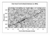
- the graph of FIG. 2illustrates player test data with drivers having an FB dimension greater than 3.6 inches.
- the graphillustrates considerably lower club head speeds for large FB dimension drivers when compared to the club head speeds of drivers having FB dimensions less than 4.4 inches.
- a club head speed of 104.6 mphwas achieved when swinging a driver having a FB dimension of less than 3.8 inches, while the swing speed dropped over 3% to 101.5 mph when swinging a driver with a FB dimension of slightly less than 4.8 inches.
- orientation oneis identified in FIG. 11 with a flow arrow labeled as “Air Flow—90°” and is referred to in the graphs of the figures as “lie 90 degree orientation.”
- This orientationcan be thought of as the club head resting on the ground plane (GP) with the shaft axis (SA) at the club head's design lie angle, as seen in FIG. 8 .
- SAshaft axis
- a 100 mph windis directed parallel to the ground plane (GP) directly at the club face ( 200 ), as illustrated by the flow arrow labeled “Air Flow—90°” in FIG. 11 .
- orientation twois identified in FIG. 11 with a flow arrow labeled as “Air Flow—60°” and is referred to in the graphs of the figures as “lie 60 degree orientation.”
- This orientationcan be thought of as the club head resting on the ground plane (GP) with the shaft axis (SA) at the club head's design lie angle, as seen in FIG. 8 .
- SAshaft axis
- a 100 mph windis wind is oriented thirty degrees from a vertical plane normal to the face ( 200 ) with the wind originating from the heel ( 116 ) side of the club head, as illustrated by the flow arrow labeled “Air Flow—60°” in FIG. 11 .
- orientation threeis identified in FIG. 12 with a flow arrow labeled as “Air Flow—Vert.—0°” and is referred to in the graphs of the figures as “vertical 0 degree orientation.”
- This orientationcan be thought of as the club head being oriented upside down with the shaft axis (SA) vertical while being exposed to a horizontal 100 mph wind directed at the heel ( 116 ), as illustrated by the flow arrow labeled “Air Flow—Vert.—0°” in FIG. 12 .
- the air flowis parallel to the vertical plane created by the shaft axis (SA) seen in FIG. 11 , blowing from the heel ( 116 ) to the toe ( 118 ) but with the club head oriented as seen in FIG. 12 .
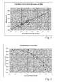
- the normalized aerodynamic drag forceincreases non-linearly from a low of 1.2 lbf with a short 3.8 inch FB dimension club head to a high of 2.65 lbf for a club head having a FB dimension of almost 4.8 inches.
- the increase in normalized aerodynamic drag forceis in excess of 120% as the FB dimension increases slightly less than one inch, contributing to the significant decrease in club head speed previously discussed.
- the graph of FIG. 6correlates the player test club head speed data of FIG. 2 with the maximum normalized aerodynamic drag force for each club head from FIG. 3, 4 , or 5 .
- FIG. 6shows that the club head speed drops from 104.6 mph, when the maximum normalized aerodynamic drag force is only 1.2 lbf, down to 101.5 mph, when the maximum normalized aerodynamic drag force is 2.65 lbf.
- the drop in club head speed just describedhas a significant impact on the speed at which the golf ball leaves the club face after impact and thus the distance that the golf ball travels. In fact, for a club head speed of approximately 100 mph, each 1 mph reduction in club head speed results in approximately a 1% loss in distance.
- the present golf club headhas identified these relationships, the reason for the drop in club head speed associated with long FB dimension clubs, and several ways to reduce the aerodynamic drag force of golf club heads.
- the claimed aerodynamic golf club head having a post apex attachment promoting regionhas recognized that the poor aerodynamic performance of large FB dimension drivers is not due solely to the large FB dimension; rather, in an effort to create large FB dimension drivers with a high MOIy value and low center of gravity (CG) dimension, golf club designers have generally created clubs that have very poor aerodynamic shaping.
- CGcenter of gravity
- Several problemsare the lack of proper shaping to account for airflow reattachment in the crown area trailing the face, the lack of proper shaping to promote airflow attachment after is passes the highest point on the crown, and the lack of proper trailing edge design.
- current large FB dimension driver designshave ignored, or even tried to maximize in some cases, the frontal cross sectional area of the golf club head which increases the aerodynamic drag force.
- the present aerodynamic golf club head having a post apex attachment promoting regionsolves these issues and results in a high volume aerodynamic golf club head having a relatively large FB dimension with beneficial moment of inertia values, while also obtaining superior aerodynamic properties unseen by other large volume, large FB dimension, high MOI golf club heads.
- the golf club headobtains superior aerodynamic performance through the use of unique club head shapes and the incorporation of a having a post apex attachment promoting region directed to keeping the airflow attached to the club head as it passes the crown apex.
- the club headhas a crown section having a post apex attachment promoting region that at the crown apex and extends toward the back of the club head.
- the post apex attachment promoting regionis a relatively flat portion of the crown section that is behind the crown apex, yet above the maximum height on the face of the club head.
- the post apex attachment promoting regionaides in keeping airflow attached to the club head once it flows past the crown apex thereby resulting in reduced aerodynamic drag forces and producing higher club head speeds.
- FIG. 1shows a graph of FB dimensions versus MOIy
- FIG. 2shows a graph of FB dimensions versus club head speed
- FIG. 3shows a graph of FB dimensions versus club head normalized aerodynamic drag force
- FIG. 4shows a graph of FB dimensions versus club head normalized aerodynamic drag force
- FIG. 5shows a graph of FB dimensions versus club head normalized aerodynamic drag force
- FIG. 6shows a graph of club head normalized aerodynamic drag force versus club head speed
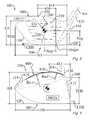
- FIG. 7shows a top plan view of a high volume aerodynamic golf club head, not to scale
- FIG. 8shows a front elevation view of a high volume aerodynamic golf club head, not to scale
- FIG. 9shows a toe side elevation view of a high volume aerodynamic golf club head, not to scale
- FIG. 10shows a front elevation view of a high volume aerodynamic golf club head, not to scale
- FIG. 11shows a top plan view of a high volume aerodynamic golf club head, not to scale
- FIG. 12shows a rotated front elevation view of a high volume aerodynamic golf club head with a vertical shaft axis orientation, not to scale;
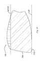
- FIG. 13shows a front elevation view of a high volume aerodynamic golf club head, not to scale
- FIG. 14shows a top plan view of a high volume aerodynamic golf club head having a post apex attachment promoting region, not to scale;
- FIG. 15shows a top plan view of a high volume aerodynamic golf club head having a post apex attachment promoting region, not to scale;
- FIG. 16shows a top plan view of a high volume aerodynamic golf club head having a post apex attachment promoting region, not to scale;
- FIG. 17shows a top plan view of a high volume aerodynamic golf club head having a post apex attachment promoting region, not to scale;
- FIG. 18shows a partial isometric view of a high volume aerodynamic golf club head having a post apex attachment promoting region intersected by the maximum top edge plane, not to scale;
- FIG. 19shows a cross-sectional view taken through a center of the face of a high volume aerodynamic golf club head having a post apex attachment promoting region, not to scale;
- FIG. 20shows a cross-sectional view taken through a center of the face of a high volume aerodynamic golf club head having a post apex attachment promoting region, not to scale;
- FIG. 21shows a heel-side elevation view of a high volume aerodynamic golf club head having a post apex attachment promoting region, not to scale;
- FIG. 22shows a toe-side elevation view of a high volume aerodynamic golf club head having a post apex attachment promoting region, not to scale;
- FIG. 23shows a rear elevation view of a high volume aerodynamic golf club head having a post apex attachment promoting region, not to scale;
- FIG. 24shows a bottom plan view of a high volume aerodynamic golf club head having a post apex attachment promoting region, not to scale.
- FIG. 25shows a top plan view of a high volume aerodynamic golf club head having a post apex attachment promoting region, not to scale.
- the claimed high volume aerodynamic golf club head ( 100 )enables a significant advance in the state of the art.
- the preferred embodiments of the club head ( 100 )accomplish this by new and novel arrangements of elements and methods that are configured in unique and novel ways and which demonstrate previously unavailable but preferred and desirable capabilities.
- the description set forth below in connection with the drawingsis intended merely as a description of the presently preferred embodiments of the club head ( 100 ), and is not intended to represent the only form in which the club head ( 100 ) may be constructed or utilized.
- the descriptionsets forth the designs, functions, means, and methods of implementing the club head ( 100 ) in connection with the illustrated embodiments. It is to be understood, however, that the same or equivalent functions and features may be accomplished by different embodiments that are also intended to be encompassed within the spirit and scope of the club head ( 100 ).
- the present high volume aerodynamic golf club head ( 100 )has recognized that the poor aerodynamic performance of large FB dimension drivers is not due solely to the large FB dimension; rather, in an effort to create large FB dimension drivers with a high MOIy value and low center of gravity (CG) dimension, golf club designers have generally created clubs that have very poor aerodynamic shaping.
- the main problemsare the significantly flat surfaces on the body, the lack of proper shaping to account for airflow reattachment in the crown area trailing the face, and the lack of proper trailing edge design.
- current large FB dimension driver designshave ignored, or even tried to maximize in some cases, the frontal cross sectional area of the golf club head which increases the aerodynamic drag force.
- the present aerodynamic golf club head ( 100 )solves these issues and results in a high volume aerodynamic golf club head ( 100 ) having a large FB dimension and a high MOIy.
- the present high volume aerodynamic golf club head ( 100 )has a volume of at least 400 cc. It is characterized by a face-on normalized aerodynamic drag force of less than 1.5 lbf when exposed to a 100 mph wind parallel to the ground plane (GP) when the high volume aerodynamic golf club head ( 100 ) is positioned in a design orientation and the wind is oriented at the front ( 112 ) of the high volume aerodynamic golf club head ( 100 ), as previously described with respect to FIG. 11 and the flow arrow labeled “air flow—90.” As explained in the “Background” section, but worthy of repeating in this section, all of the aerodynamic drag forces mentioned herein, unless otherwise stated, are aerodynamic drag forces normalized to a 120 mph airstream velocity.
- the above mentioned normalized aerodynamic drag force of less than 1.5 lbf when exposed to a 100 mph windis the actual measured drag force at the indicated 100 mph airstream velocity multiplied by the square of the reference velocity, which is 120 mph, then divided by the square of the actual airstream velocity, which is 100 mph.
- the high volume aerodynamic golf club head ( 100 )includes a hollow body ( 110 ) having a face ( 200 ), a sole section ( 300 ), and a crown section ( 400 ).
- the hollow body ( 110 )may be further defined as having a front ( 112 ), a back ( 114 ), a heel ( 116 ), and a toe ( 118 ).
- the hollow body ( 110 )has a front-to-back dimension (FB) of at least 4.4 inches, as previously defined and illustrated in FIG. 7 .
- the relatively large FB dimension of the present high volume aerodynamic golf club head ( 100 )aids in obtaining beneficial moment of inertia values while also obtaining superior aerodynamic properties unseen by other large volume, large FB dimension, high MOI golf club heads.
- an embodiment of the high volume aerodynamic golf club head ( 100 )obtains a first moment of inertia (MOIy) about a vertical axis through a center of gravity (CG) of the golf club head ( 100 ), illustrated in FIG. 7 , that is at least 4000 g*cm 2 .
- MOIyis the moment of inertia of the golf club head ( 100 ) that resists opening and closing moments induced by ball strikes towards the toe side or heel side of the face.
- this embodimentobtains a second moment of inertia (MOIx) about a horizontal axis through the center of gravity (CG), as seen in FIG. 9 , that is at least 2000 g*cm 2 .
- MOIxis the moment of inertia of the golf club head ( 100 ) that resists lofting and delofting moments induced by ball strikes high or low on the face ( 200 ).
- the golf club head ( 100 )obtains superior aerodynamic performance through the use of unique club head shapes.
- the crown section ( 400 )has a crown apex ( 410 ) located an apex height (AH) above a ground plane (GP).
- the crown section ( 400 )has three distinct radii that improve the aerodynamic performance of the present club head ( 100 ). First, as seen in FIG.
- a portion of the crown section ( 400 ) between the crown apex ( 410 ) and the front ( 112 )has an apex-to-front radius of curvature (Ra-f) that is less than 3 inches.
- the apex-to-front radius of curvature (Ra-f)is measured in a vertical plane that is perpendicular to a vertical plane passing through the shaft axis (SA), and the apex-to-front radius of curvature (Ra-f) is further measured at the point on the crown section ( 400 ) between the crown apex ( 410 ) and the front ( 112 ) that has the smallest the radius of curvature.
- At least fifty percent of the vertical plane cross sections taken perpendicular to a vertical plane passing through the shaft axis (SA), which intersect a portion of a face top edge ( 210 ),are characterized by an apex-to-front radius of curvature (Ra-f) of less than 3 inches.
- at least ninety percent of the vertical plane cross sections taken perpendicular to a vertical plane passing through the shaft axis (SA), which intersect a portion of the face top edge ( 210 )are characterized by an apex-to-front radius of curvature (Ra-f) of less than 3 inches.
- At least fifty percent of the vertical plane cross sections taken perpendicular to a vertical plane passing through the shaft axis (SA), which intersect a portion of the face top edge ( 210 ) between the center of the face ( 200 ) and the toeward most point on the face ( 200 ),are characterized by an apex-to-front radius of curvature (Ra-f) of less than 3 inches.
- another embodimenthas at least fifty percent of the vertical plane cross sections taken perpendicular to a vertical plane passing through the shaft axis (SA), which intersect a portion of the face top edge ( 210 ) between the center of the face ( 200 ) and the toeward most point on the face ( 200 ), are characterized by an apex-to-front radius of curvature (Ra-f) of less than 3 inches.
- the center of the face ( 200 )shall be determined in accordance with the USGA “Procedure for Measuring the Flexibility of a Golf Clubhead,” Revision 2.0, Mar. 25, 2005, which is incorporated herein by reference.
- This USGA procedureidentifies a process for determining the impact location on the face of a golf club that is to be tested, also referred therein as the face center.
- the USGA procedureutilizes a template that is placed on the face of the golf club to determine the face center.
- a portion of the crown section ( 400 ) between the crown apex ( 410 ) and the back ( 114 ) of the hollow body ( 110 )has an apex-to-rear radius of curvature (Ra-r) that is less than 3.75 inches.
- the apex-to-rear radius of curvature (Ra-r)is also measured in a vertical plane that is perpendicular to a vertical plane passing through the shaft axis (SA), and the apex-to-rear radius of curvature (Ra-r) is further measured at the point on the crown section ( 400 ) between the crown apex ( 410 ) and the back ( 114 ) that has the smallest the radius of curvature.
- At least fifty percent of the vertical plane cross sections taken perpendicular to a vertical plane passing through the shaft axis (SA), which intersect a portion of the face top edge ( 210 ),are characterized by an apex-to-rear radius of curvature (Ra-r) of less than 3.75 inches.
- at least ninety percent of the vertical plane cross sections taken perpendicular to a vertical plane passing through the shaft axis (SA), which intersect a portion of the face top edge ( 210 )are characterized by an apex-to-rear radius of curvature (Ra-r) of less than 3.75 inches.
- one hundred percent of the vertical plane cross sections taken perpendicular to a vertical plane passing through the shaft axis (SA), which intersect a portion of the face top edge ( 210 ) between the center of the face ( 200 ) and the toeward most point on the face ( 200 ),are characterized by an apex-to-rear radius of curvature (Ra-r) of less than 3.75 inches.
- a portion of the crown section ( 400 )has a heel-to-toe radius of curvature (Rh-t) at the crown apex ( 410 ) in a direction parallel to the vertical plane created by the shaft axis (SA) that is less than 4 inches.
- at least ninety percent of the crown section ( 400 ) located between the most heelward point on the face ( 200 ) and the most toeward point on the face ( 200 )has a heel-to-toe radius of curvature (Rh-t) at the crown apex ( 410 ) in a direction parallel to the vertical plane created by the shaft axis (SA) that is less than 4 inches.
- a further embodimenthas one hundred percent of the crown section ( 400 ) located between the most heelward point on the face ( 200 ) and the most toeward point on the face ( 200 ) exhibiting a heel-to-toe radius of curvature (Rh-t), at the crown apex ( 410 ) in a direction parallel to the vertical plane created by the shaft axis (SA), that is less than 4 inches.
- Rh-theel-to-toe radius of curvature
- the face ( 200 )has a top edge ( 210 ) and a lower edge ( 220 ).
- the top edge ( 210 )has a top edge height (TEH) that is the elevation of the top edge ( 210 ) above the ground plane (GP).
- the lower edge ( 220 )has a lower edge height (LEH) that is the elevation of the lower edge ( 220 ) above the ground plane (GP).
- the highest point along the top edge ( 210 )produces a maximum top edge height (TEH) that is at least 2 inches.
- the lowest point along the lower edge ( 220 )is a minimum lower edge height (LEH).
- the apex ratiois the ratio of apex height (AH) to the maximum top edge height (TEH).
- AHapex height
- THtop edge height
- the apex ratiois at least 1.13, thereby encouraging airflow reattachment as soon as possible.
- this embodiment of the club head ( 100 )has a frontal cross sectional area that is less than 11 square inches.
- the frontal cross sectional areais the single plane area measured in a vertical plane bounded by the outline of the golf club head ( 100 ) when it is resting on the ground plane (GP) at the design lie angle and viewed from directly in front of the face ( 200 ).
- the frontal cross sectional areais illustrated by the cross-hatched area of FIG. 13 .
- a second aerodynamic drag forceis introduced, namely the 30 degree offset aerodynamic drag force, as previously explained with reference to FIG. 11 .
- the 30 degree offset normalized aerodynamic drag forceis less than 1.3 lbf when exposed to a 100 mph wind parallel to the ground plane (GP) when the high volume aerodynamic golf club head ( 100 ) is positioned in a design orientation and the wind is oriented thirty degrees from a vertical plane normal to the face ( 200 ) with the wind originating from the heel ( 116 ) side of the high volume aerodynamic golf club head ( 100 ).
- introducing a 30 degree offset normalized aerodynamic drag force of less than 1.3 lbffurther reduces the drop in club head speed associated with large volume, large FB dimension golf club heads.
- Yet another embodimentintroduces a third aerodynamic drag force, namely the heel normalized aerodynamic drag force, as previously explained with reference to FIG. 12 .
- the heel normalized aerodynamic drag forceis less than 1.9 lbf when exposed to a horizontal 100 mph wind directed at the heel ( 116 ) with the body ( 110 ) oriented to have a vertical shaft axis (SA).
- SAvertical shaft axis
- having the face-on normalized aerodynamic drag force of less than 1.5 lbf and the 30 degree offset normalized aerodynamic drag force of less than 1.3 lbfhaving a heel normalized aerodynamic drag force of less than 1.9 lbf further reduces the drop in club head speed associated with large volume, large FB dimension golf club heads.
- a still further embodimenthas recognized that having the apex-to-front radius of curvature (Ra-f) at least 25% less than the apex-to-rear radius of curvature (Ra-r) produces a particularly aerodynamic golf club head ( 100 ) further assisting in airflow reattachment and preferred airflow attachment over the crown section ( 400 ).
- Yet another embodimentfurther encourages quick airflow reattachment by incorporating an apex ratio of the apex height (AH) to the maximum top edge height (TEH) that is at least 1.2. This concept is taken even further in yet another embodiment in which the apex ratio of the apex height (AH) to the maximum top edge height (TEH) is at least 1.25. Again, these large apex ratios produce a bulbous crown section ( 400 ) that facilitates airflow reattachment as close to the face ( 200 ) as possible, thereby resulting in reduced aerodynamic drag forces and resulting in higher club head speeds.
- Reducing aerodynamic drag by encouraging airflow reattachment, or conversely discouraging extended lengths of airflow separationmay be further obtained in yet another embodiment in which the apex-to-front radius of curvature (Ra-f) is less than the apex-to-rear radius of curvature (Ra-r), and the apex-to-rear radius of curvature (Ra-r) is less than the heel-to-toe radius of curvature (Rh-t).
- apex-to-front radius of curvatureRa-f
- the apex-to-rear radius of curvature (Ra-r)is less than the heel-to-toe radius of curvature (Rh-t).
- a high volume aerodynamic golf club head ( 100 ) having the apex-to-front radius of curvature (Ra-f) less than 2.85 inches and the heel-to-toe radius of curvature (Rh-t) less than 3.85 inchesproduces a reduced face-on aerodynamic drag force.
- Another embodimentfocuses on the playability of the high volume aerodynamic golf club head ( 100 ) by having a maximum top edge height (TEH) that is at least 2 inches, thereby ensuring that the face area is not reduced to an unforgiving level. Even further, another embodiment incorporates a maximum top edge height (TEH) that is at least 2.15 inches, further instilling confidence in the golfer that they are not swinging a golf club head ( 100 ) with a small striking face ( 200 ).
- FBfront-to-back dimension
- FBfront-to-back dimension
- FBfront-to-back dimension
- Yet a further embodimentbalances all of the radii of curvature requirements to obtain a high volume aerodynamic golf club head ( 100 ) while minimizing the risk of an unnatural appearing golf club head by ensuring that less than 10% of the club head volume is above the elevation of the maximum top edge height (TEH).
- a further embodimentaccomplishes the goals herein with a golf club head ( 100 ) having between 5% to 10% of the club head volume located above the elevation of the maximum top edge height (TEH). This range achieves the desired crown apex ( 410 ) and radii of curvature to ensure desirable aerodynamic drag while maintaining an aesthetically pleasing look of the golf club head ( 100 ).
- the location of the crown apex ( 410 )is dictated to a degree by the apex-to-front radius of curvature (Ra-f); however, yet a further embodiment identifies that the crown apex ( 410 ) should be behind the forwardmost point on the face ( 200 ) a distance that is a crown apex setback dimension ( 412 ), seen in FIG. 9 , which is greater than 10% of the FB dimension and less than 70% of the FB dimension, thereby further reducing the period of airflow separation and resulting in desirable airflow over the crown section ( 400 ).
- a crown apex setback dimension ( 412 )that is less than 1.75 inches.
- An even further embodimentbalances playability with the volume shift toward the face ( 200 ) inherent in the present club head ( 100 ) by positioning the performance mass to produce a center of gravity (CG) further away from the forwardmost point on the face ( 200 ) than the crown apex setback dimension ( 412 ).
- CGcenter of gravity
- the heel-to-toe location of the crown apex ( 410 )also plays a significant role in the aerodynamic drag force.
- the location of the crown apex ( 410 ) in the heel-to-toe directionis identified by the crown apex ht dimension ( 414 ), as seen in FIG. 8 .
- This figurealso introduces a heel-to-toe (HT) dimension which is measured in accordance with USGA rules.
- the location of the crown apex ( 410 )is dictated to a degree by the heel-to-toe radius of curvature (Rh-t); however, yet a further embodiment identifies that the crown apex ( 410 ) location should result in a crown apex ht dimension ( 414 ) that is greater than 30% of the HT dimension and less than 70% of the HT dimension, thereby aiding in reducing the period of airflow separation.
- the crown apex ( 410 )is located in the heel-to-toe direction between the center of gravity (CG) and the toe ( 118 ).
- the present high volume aerodynamic golf club head ( 100 )has a club head volume of at least 400 cc. Further embodiments incorporate the various features of the above described embodiments and increase the club head volume to at least 440 cc, or even further to the current USGA limit of 460 cc. However, one skilled in the art will appreciate that the specified radii and aerodynamic drag requirements are not limited to these club head sizes and apply to even larger club head volumes. Likewise, a heel-to-toe (HT) dimension of the present club head ( 100 ), as seen in FIG. 8 , is greater than the FB dimension, as measured in accordance with USGA rules.
- HTheel-to-toe
- the hollow body ( 110 )has a center of gravity (CG).
- the location of the center of gravity (CG)is described with reference to an origin point, seen in FIG. 8 .
- the origin pointis the point at which a shaft axis (SA) with intersects with a horizontal ground plane (GP).
- the hollow body ( 110 )has a bore having a center that defines the shaft axis (SA).
- the boreis present in club heads having traditional hosels, as well as hosel-less club heads.
- the center of gravity (CG)is located vertically toward the crown section ( 400 ) from the origin point a distance Ycg in a direction orthogonal to the ground plane (GP), as seen in FIG. 8 .
- the center of gravity (CG)is located horizontally from the origin point toward the toe ( 118 ) a distance Xcg that is parallel to a vertical plane defined by the shaft axis (SA) and parallel to the ground plane (GP).
- the center of gravity (CG)is located a distance Zcg, seen in FIG. 14 , from the origin point toward the back ( 114 ) in a direction orthogonal to the vertical direction used to measure Ycg and orthogonal to the horizontal direction used to measure Xcg.
- FIGS. 14-25incorporate a post apex attachment promoting region ( 420 ) on the surface of the crown section ( 400 ) at an elevation above a maximum top edge plane (MTEP), illustrated in FIGS. 18, 19, and 22 , wherein the post apex attachment promoting region ( 420 ) begins at the crown apex ( 410 ) and extends toward the back ( 114 ) of the club head ( 100 ).
- the incorporation of this post apex attachment promoting region ( 420 )creates a high volume aerodynamic golf club head having a post apex attachment promoting region ( 100 ) as seen in several embodiments in FIGS. 14-25 .
- the post apex attachment promoting region ( 420 )is a relatively flat portion of the crown section ( 400 ) that is behind the crown apex ( 410 ), yet above the maximum top edge plane (MTEP), and aids in keeping airflow attached to the club head ( 100 ) once it flows past the crown apex ( 410 ).
- the embodiments containing the post apex attachment promoting region ( 420 )include a maximum top edge height (TEH) of at least 2 inches and an apex ratio of the apex height (AH) to the maximum top edge height (TEH) of at least 1.13.
- the crown apex ( 410 )is located a distance from the origin point toward the toe ( 118 ) a crown apex x-dimension ( 416 ) distance that is parallel to the vertical plane defined by the shaft axis (SA) and parallel to the ground plane (GP).
- the crown section ( 400 )includes a post apex attachment promoting region ( 420 ) on the surface of the crown section ( 400 ).
- a post apex attachment promoting region ( 420 )on the surface of the crown section ( 400 ).
- Many of the previously described embodimentsincorporate characteristics of the crown section ( 400 ) located between the crown apex ( 410 ) and the face ( 200 ) that promote airflow attachment to the club head ( 100 ) thereby reducing aerodynamic drag.
- the post apex attachment promoting region ( 420 )is also aimed at reducing aerodynamic drag by encouraging the airflow passing over the crown section ( 400 ) to stay attached to the club head ( 100 ); however, the post apex attachment promoting region ( 420 ) is located between the crown apex ( 410 ) and the back ( 114 ) of the club head ( 100 ), while also being above the maximum top edge height (TEH), and thus above the maximum top edge plane (MTEP).
- the present club head ( 100 )has recognized the significance of proper club head shaping to account for rapid airflow reattachment in the crown section ( 400 ) trailing the face ( 200 ) via the apex ratio, as well as encouraging the to airflow remain attached to the club head ( 100 ) behind the crown apex ( 410 ) via the apex ratio and the post apex attachment promoting region ( 420 ).
- the post apex attachment promoting region ( 420 )includes an attachment promoting region length ( 422 ) measured along the surface of the crown section ( 400 ) and orthogonal to the vertical plane defined by the shaft axis (SA).
- the attachment promoting region length ( 422 )is at least as great as fifty percent of the crown apex setback dimension ( 412 ).
- the post apex attachment promoting region ( 420 )also has an apex promoting region width ( 424 ) measured along the surface of the crown section ( 400 ) in a direction parallel to the vertical plane defined by the shaft axis (SA).
- the attachment promoting region width ( 424 )is at least as great as the difference between the crown apex x-dimension ( 416 ) and the distance Xcg.
- the relationship of the attachment promoting region length ( 422 ) to the crown apex setback dimension ( 412 )recognizes the natural desire of the airflow to separate from the club head ( 100 ) as it passes over the crown apex ( 410 ).
- the relationship of the attachment promoting region width ( 424 ) to the difference between the crown apex x-dimension ( 416 ) and the distance Xcgrecognizes the natural desire of the airflow to separate from the club head ( 100 ) as it passes over the crown apex ( 410 ) in a direction other than directly from the face ( 200 ) to the back ( 114 ).
- Incorporating a post apex attachment promoting region ( 420 ) that has the claimed length ( 422 ) and width ( 424 )establishes the amount of the club head ( 100 ) that is above the maximum top edge plane (MTEP) and behind the crown apex ( 410 ).
- FIG. 16illustrates an elliptical post apex attachment promoting region ( 420 ) having both a length ( 422 ) and a width ( 424 ), which may be thought of as a major axis and a minor axis.
- the post apex attachment promoting region ( 420 )may be in the shape of any polygon or curved object including, but not limited to, triangles (equilateral, scalene, isosceles, right, acute, obtuse, etc.), quadrilaterals (trapezoid, parallelogram, rectangle, square, rhombus, kite), polygons, circles, ellipses, and ovals.
- the post apex attachment promoting region ( 420 )is simply an area on the surface of the crown section ( 400 ) possessing the claimed attributes, and one skilled in the art will recognize that it will blend into the rest of the crown section ( 400 ) and may be indistinguishable by the naked eye.
- the present embodiment incorporating the post apex attachment promoting region ( 420 ) located behind the crown apex ( 410 )also has a face-on normalized aerodynamic drag force of less than 1.5 lbf when exposed to a 100 mph wind parallel to the ground plane (GP) when the high volume aerodynamic golf club head having a post apex attachment promoting region ( 100 ) is positioned in a design orientation and the wind is oriented at the front ( 112 ) of the high volume aerodynamic golf club head having a post apex attachment promoting region ( 100 ), as previously explained in detail.
- GPground plane
- a second aerodynamic drag forceis introduced, namely the 30 degree offset aerodynamic drag force, as previously explained with reference to FIG. 11 .
- the 30 degree offset normalized aerodynamic drag forceis less than 1.3 lbf when exposed to a 100 mph wind parallel to the ground plane (GP) when the high volume aerodynamic golf club head having a post apex attachment promoting region ( 100 ) is positioned in a design orientation and the wind is oriented thirty degrees from a vertical plane normal to the face ( 200 ) with the wind originating from the heel ( 116 ) side of the high volume aerodynamic golf club head having a post apex attachment promoting region ( 100 ).
- introducing a 30 degree offset normalized aerodynamic drag force of less than 1.3 lbffurther reduces the drop in club head speed associated with large volume, large FB dimension golf club heads.
- Yet another embodimentintroduces a third aerodynamic drag force, namely the heel normalized aerodynamic drag force, as previously explained with reference to FIG. 12 .
- the heel normalized aerodynamic drag forceis less than 1.9 lbf when exposed to a horizontal 100 mph wind directed at the heel ( 116 ) with the body ( 110 ) oriented to have a vertical shaft axis (SA).
- SAvertical shaft axis
- having the face-on normalized aerodynamic drag force of less than 1.5 lbf and the 30 degree offset normalized aerodynamic drag force of less than 1.3 lbfhaving a heel normalized aerodynamic drag force of less than 1.9 lbf further reduces the drop in club head speed associated with large volume, large FB dimension golf club heads.
- the post apex attachment promoting region ( 420 )is located above the maximum top edge plane (MTEP), which means that if the apex ratio is less than 1 then there can be no post apex attachment promoting region ( 420 ).
- An apex ratio of at least 1.13provides for the height of the crown apex ( 410 ) that enables the incorporation of the post apex attachment promoting region ( 420 ) to reduce aerodynamic drag forces. Yet another embodiment further encourages airflow attachment behind the crown apex ( 410 ) by incorporating an apex ratio that is at least 1.2, thereby further increasing the available area on the crown section ( 400 ) above the maximum top edge height (TEH) suitable for a post apex attachment promoting region ( 420 ).
- the attachment promoting region length ( 422 )is at least as great as seventy five percent of the crown apex setback dimension ( 412 ). As the attachment promoting region length ( 422 ) increases in proportion to the crown apex setback dimension ( 412 ), the amount of airflow separation behind the crown apex ( 410 ) is reduced.
- the geometry of the club head ( 100 )is partially defined in that the amount of crown section ( 400 ) above the maximum top edge plane (MTEP) is set, thereby establishing the deviation of the crown section ( 400 ) from the crown apex ( 410 ) in the area behind the crown apex ( 410 ).
- MTEPmaximum top edge plane
- at least a portion of the crown section ( 400 ) behind the crown apex ( 410 )must be relatively flat, or deviate from an apex plane (AP), seen in FIG. 22 , by less than twenty degrees thereby reducing the amount of airflow separation behind the crown apex ( 410 ).
- the apex promoting region width ( 424 )is at least twice as great as the difference between the crown apex x-dimension ( 416 ) and the distance Xcg. As the apex promoting region width ( 424 ) increases, more airflow coming over the crown apex ( 410 ) is exposed to the post apex attachment promoting region ( 420 ) further promoting airflow attachment to the club head ( 100 ) behind the crown apex ( 410 ) and reducing aerodynamic drag force.
- Yet another embodimentfocuses not solely on the size of the post apex attachment promoting region ( 420 ), but also on the location of it. It is helpful to define a new dimension to further characterize the placement of the post apex attachment promoting region ( 420 ); namely, as seen in FIG. 17 , the hollow body ( 110 ) has a crown apex-to-toe dimension ( 418 ) measured from the crown apex ( 410 ) to the toewardmost point on the hollow body ( 110 ) in a direction parallel to the vertical plane defined by the shaft axis (SA) and parallel to the ground plane (GP).
- SAshaft axis
- GPground plane
- the present embodimentrecognizes the significance of having the major portion of the crown section ( 400 ) between the crown apex ( 410 ) and the toe ( 118 ) incorporating a post apex attachment promoting region ( 420 ).
- the post apex attachment promoting region width ( 424 )is at least fifty percent of the crown apex-to-toe dimension ( 418 ).
- at least fifty percent of the crown apex-to-toe dimension ( 418 )includes a portion of the post apex attachment promoting region ( 420 ).
- Another embodimentbuilds upon the post apex attachment promoting region ( 420 ) by having at least 7.5 percent of the club head volume located above the maximum top edge plane (MTEP), illustrated in FIG. 18 . Incorporating such a volume above the maximum top edge plane (MTEP) increases the surface area of the club head ( 100 ) above the maximum top edge height (TEH) facilitating the post apex attachment promoting region ( 420 ) and reducing airflow separation between the crown apex ( 410 ) and the back ( 114 ) of the club head ( 100 ).
- TSHmaximum top edge height
- a club head ( 100 ) designcharacterized by a vertical cross-section taken through the hollow body ( 110 ) at a center of the face ( 200 ) extending orthogonal to the vertical plane through the shaft axis (SA) has at least 7.5 percent of the cross-sectional area located above the maximum top edge plane (MTEP).
- MTEPmaximum top edge plane
- at least a portion of the crown section ( 400 )has to be relatively flat and not aggressively sloped from the crown apex ( 410 ) toward the ground plane (GP).
- a portion of the post apex attachment promoting region ( 420 )has an apex-to-rear radius of curvature (Ra-r), seen in FIG. 20 , that is greater than 5 inches.
- a portion of the post apex attachment promoting region ( 420 )has an apex-to-rear radius of curvature (Ra-r) that is greater than both the bulge and the roll of the face ( 200 ).
- An even further embodimenthas a portion of the post apex attachment promoting region ( 420 ) having an apex-to-rear radius of curvature (Ra-r) that is greater than 20 inches.
- FIG. 420Further embodiments incorporate a post apex attachment promoting region ( 420 ) in which a majority of the cross sections taken from the face ( 200 ) to the back ( 114 ) of the club head ( 100 ), perpendicular to the vertical plane through the shaft axis (SA), which pass through the post apex attachment promoting region ( 420 ), have an apex-to-rear radius of curvature (Ra-r) that is greater than 5 inches.
- SAshaft axis
- At least seventy five percent of the vertical plane cross sections taken perpendicular to a vertical plane passing through the shaft axis (SA), which pass through the post apex attachment promoting region ( 420 ),are characterized by an apex-to-rear radius of curvature (Ra-r) that is greater than 5 inches within the post apex attachment promoting region ( 420 ); thereby further promoting airflow attachment between the crown apex ( 410 ) and the back ( 114 ) of the club head ( 100 ).
- FIG. 20Another embodiment incorporates features that promote airflow attachment both in front of the crown apex ( 410 ) and behind the crown apex ( 410 ).
- the previously described vertical plane cross sections taken perpendicular to a vertical plane passing through the shaft axis (SA), which pass through the post apex attachment promoting region ( 420 )also have an apex-to-front radius of curvature (Ra-f) that is less than 3 inches, and wherein at least fifty percent of the vertical plane cross sections taken perpendicular to a vertical plane passing through the shaft axis (SA), which pass through the post apex attachment promoting region ( 420 ), are characterized by an apex-to-front radius of curvature (Ra-f) of at least 50% less than the apex-to-rear radius of curvature (Ra-r).
- MTEPmaximum top edge plane
- Yet another embodimenttakes this relationship further and increases the percentage of the vertical plane cross sections taken perpendicular to a vertical plane passing through the shaft axis (SA), previously discussed, to at least seventy five percent of the vertical plane cross sections taken perpendicular to a vertical plane passing through the shaft axis (SA); thus further promoting airflow attachment over the crown section ( 400 ) of the club head ( 100 ).
- the attributes of the claimed crown section ( 400 )tend to keep the crown section ( 400 ) distant from the sole section ( 300 ).
- One embodimentseen in FIGS. 21 and 22 , incorporates a skirt ( 500 ) connecting a portion of the crown section ( 400 ) to the sole section ( 300 ).
- the skirt ( 500 )includes a skirt profile ( 550 ) that is concave within a profile region angle ( 552 ), seen in FIG. 25 , originating at the crown apex ( 410 ) wherein the profile region angle ( 552 ) is at least 45 degrees.
- the concave skirt profile ( 550 )creates a skirt-to-sole transition region ( 510 ), also referred to as “SSTR,” at the connection to the sole section ( 300 ) and the skirt-to-sole transition region ( 510 ) has a rearwardmost SSTR point ( 512 ) located above the ground plane (GP) at a rearwardmost SSTR point elevation ( 513 ).
- SSTRskirt-to-sole transition region
- a skirt-to-crown transition region ( 520 ), also referred to as “SSCR,”is present at the connection to the crown section ( 400 ) and the skirt-to-crown transition region ( 520 ) has a rearwardmost SCTR point ( 522 ) located above the ground plane (GP) at a rearwardmost SCTR point elevation ( 523 ).
- the rearwardmost SSTR point ( 512 ) and the rearwardmost SCTR point ( 522 )need not be located vertically in-line with one another, however they are both located within the profile region angle ( 552 ) of FIG. 25 .
- the rearwardmost SSTR point ( 512 ) and the rearwardmost SCTR point ( 522 )are vertically separated by a vertical separation distance ( 530 ) that is at least thirty percent of the apex height (AH); while also being horizontally separated in a heel-to-toe direction by a heel-to-toe horizontal separation distance ( 545 ), seen in FIG.
- FIG. 22This combination of relationships among the elements of the skirt ( 500 ) further promotes airflow attachment in that it establishes the location and elevation of the rear of the crown section ( 400 ), and thus a profile of the crown section ( 400 ) from the crown apex ( 410 ) to the back ( 114 ) of the club head ( 100 ).
- another embodiment incorporating a rearwardmost SSTR point elevation ( 513 ) that is at least twenty five percent of the rearwardmost SCTR point elevation ( 523 )defines a sole section ( 300 ) curvature that promotes airflow attachment on the sole section ( 300 ).
- the rearwardmost SCTR point ( 522 )is substantially in-line vertically with the crown apex ( 410 ) producing the longest airflow path over the crown section ( 400 ) along the vertical cross section that passes through the crown apex ( 410 ) and thus maximizing the airflow attachment propensity of the crown section ( 400 ) design.
- a heel-to-toe horizontal separation distance ( 545 )is at least at great as the difference between the crown apex x-dimension ( 416 ) and the distance Xcg.
- a further embodimenthas the front-to-back horizontal separation distance ( 540 ) is at least thirty percent of the difference between the apex height (AH) and the maximum top edge height (TEH).
- Another embodiment advancing this principlehas the rearwardmost SSTR point ( 512 ) is located on the heel ( 116 ) side of the center of gravity, and the rearwardmost SCTR point ( 522 ) is located on the toe ( 118 ) side of the center of gravity, as seen in FIG. 23 .
- An alternative embodimenthas both the rearwardmost SSTR point and the rearwardmost SCTR point ( 522 ) located on the toe ( 118 ) side of the center of gravity, but offset by a heel-to-toe horizontal separation distance ( 545 ) that is at least as great as the difference between the apex height (AH) and the maximum top edge height (TEH).
- the various parts of the golf club head ( 100 )may be made from any suitable or desired materials without departing from the claimed club head ( 100 ), including conventional metallic and nonmetallic materials known and used in the art, such as steel (including stainless steel), titanium alloys, magnesium alloys, aluminum alloys, carbon fiber composite materials, glass fiber composite materials, carbon pre-preg materials, polymeric materials, and the like.
- the various sections of the club head ( 100 )may be produced in any suitable or desired manner without departing from the claimed club head ( 100 ), including in conventional manners known and used in the art, such as by casting, forging, molding (e.g., injection or blow molding), etc.
- the various sectionsmay be held together as a unitary structure in any suitable or desired manner, including in conventional manners known and used in the art, such as using mechanical connectors, adhesives, cements, welding, brazing, soldering, bonding, and other known material joining techniques. Additionally, the various sections of the golf club head ( 100 ) may be constructed from one or more individual pieces, optionally pieces made from different materials having different densities, without departing from the claimed club head ( 100 ).
Landscapes
- Health & Medical Sciences (AREA)
- General Health & Medical Sciences (AREA)
- Physical Education & Sports Medicine (AREA)
- Life Sciences & Earth Sciences (AREA)
- Engineering & Computer Science (AREA)
- Wood Science & Technology (AREA)
- Golf Clubs (AREA)
Abstract
Description
Claims (20)
Priority Applications (6)
| Application Number | Priority Date | Filing Date | Title |
|---|---|---|---|
| US15/334,790US9950221B2 (en) | 2008-07-15 | 2016-10-26 | Aerodynamic golf club head |
| US15/959,896US10391366B2 (en) | 2008-07-15 | 2018-04-23 | Aerodynamic golf club head |
| US16/550,361US10888747B2 (en) | 2008-07-15 | 2019-08-26 | Aerodynamic golf club head |
| US17/145,511US11465019B2 (en) | 2008-07-15 | 2021-01-11 | Aerodynamic golf club head |
| US17/963,005US12128278B2 (en) | 2008-07-15 | 2022-10-10 | Aerodynamic golf club head |
| US18/911,709US20250032866A1 (en) | 2008-07-15 | 2024-10-10 | Aerodynamic golf club head |
Applications Claiming Priority (11)
| Application Number | Priority Date | Filing Date | Title |
|---|---|---|---|
| US8089208P | 2008-07-15 | 2008-07-15 | |
| US10191908P | 2008-10-01 | 2008-10-01 | |
| US12/367,839US8083609B2 (en) | 2008-07-15 | 2009-02-09 | High volume aerodynamic golf club head |
| US12/409,998US8088021B2 (en) | 2008-07-15 | 2009-03-24 | High volume aerodynamic golf club head having a post apex attachment promoting region |
| US13/305,978US20120071268A1 (en) | 2008-07-15 | 2011-11-29 | High volume aerodynamic golf club head having a post apex attachment promoting region |
| US13/683,299US8540586B1 (en) | 2008-07-15 | 2012-11-21 | High volume aerodynamic golf club head having a post apex attachment promoting region |
| US13/960,879US8597137B1 (en) | 2008-07-15 | 2013-08-07 | High volume aerodynamic golf club head having a post apex attachment promoting region |
| US14/069,448US8771101B2 (en) | 2008-07-15 | 2013-11-01 | High volume aerodynamic golf club head having a post apex attachment promoting region |
| US14/259,475US9168433B2 (en) | 2008-07-15 | 2014-04-23 | Aerodynamic golf club head having a post apex attachment promoting region |
| US14/789,263US9504886B2 (en) | 2008-07-15 | 2015-07-01 | Multi-material aerodynamic golf club head |
| US15/334,790US9950221B2 (en) | 2008-07-15 | 2016-10-26 | Aerodynamic golf club head |
Related Parent Applications (1)
| Application Number | Title | Priority Date | Filing Date |
|---|---|---|---|
| US14/789,263ContinuationUS9504886B2 (en) | 2008-07-15 | 2015-07-01 | Multi-material aerodynamic golf club head |
Related Child Applications (1)
| Application Number | Title | Priority Date | Filing Date |
|---|---|---|---|
| US15/959,896ContinuationUS10391366B2 (en) | 2008-07-15 | 2018-04-23 | Aerodynamic golf club head |
Publications (2)
| Publication Number | Publication Date |
|---|---|
| US20170043224A1 US20170043224A1 (en) | 2017-02-16 |
| US9950221B2true US9950221B2 (en) | 2018-04-24 |
Family
ID=41530786
Family Applications (11)
| Application Number | Title | Priority Date | Filing Date |
|---|---|---|---|
| US12/409,998Active2029-08-08US8088021B2 (en) | 2008-07-15 | 2009-03-24 | High volume aerodynamic golf club head having a post apex attachment promoting region |
| US13/305,978AbandonedUS20120071268A1 (en) | 2008-07-15 | 2011-11-29 | High volume aerodynamic golf club head having a post apex attachment promoting region |
| US13/683,299ActiveUS8540586B1 (en) | 2008-07-15 | 2012-11-21 | High volume aerodynamic golf club head having a post apex attachment promoting region |
| US13/960,879ActiveUS8597137B1 (en) | 2008-07-15 | 2013-08-07 | High volume aerodynamic golf club head having a post apex attachment promoting region |
| US14/069,448ActiveUS8771101B2 (en) | 2008-07-15 | 2013-11-01 | High volume aerodynamic golf club head having a post apex attachment promoting region |
| US14/259,475ActiveUS9168433B2 (en) | 2008-07-15 | 2014-04-23 | Aerodynamic golf club head having a post apex attachment promoting region |
| US14/789,263ActiveUS9504886B2 (en) | 2008-07-15 | 2015-07-01 | Multi-material aerodynamic golf club head |
| US15/334,790ActiveUS9950221B2 (en) | 2008-07-15 | 2016-10-26 | Aerodynamic golf club head |
| US15/959,896ActiveUS10391366B2 (en) | 2008-07-15 | 2018-04-23 | Aerodynamic golf club head |
| US17/963,005Active2029-09-10US12128278B2 (en) | 2008-07-15 | 2022-10-10 | Aerodynamic golf club head |
| US18/911,709PendingUS20250032866A1 (en) | 2008-07-15 | 2024-10-10 | Aerodynamic golf club head |
Family Applications Before (7)
| Application Number | Title | Priority Date | Filing Date |
|---|---|---|---|
| US12/409,998Active2029-08-08US8088021B2 (en) | 2008-07-15 | 2009-03-24 | High volume aerodynamic golf club head having a post apex attachment promoting region |
| US13/305,978AbandonedUS20120071268A1 (en) | 2008-07-15 | 2011-11-29 | High volume aerodynamic golf club head having a post apex attachment promoting region |
| US13/683,299ActiveUS8540586B1 (en) | 2008-07-15 | 2012-11-21 | High volume aerodynamic golf club head having a post apex attachment promoting region |
| US13/960,879ActiveUS8597137B1 (en) | 2008-07-15 | 2013-08-07 | High volume aerodynamic golf club head having a post apex attachment promoting region |
| US14/069,448ActiveUS8771101B2 (en) | 2008-07-15 | 2013-11-01 | High volume aerodynamic golf club head having a post apex attachment promoting region |
| US14/259,475ActiveUS9168433B2 (en) | 2008-07-15 | 2014-04-23 | Aerodynamic golf club head having a post apex attachment promoting region |
| US14/789,263ActiveUS9504886B2 (en) | 2008-07-15 | 2015-07-01 | Multi-material aerodynamic golf club head |
Family Applications After (3)
| Application Number | Title | Priority Date | Filing Date |
|---|---|---|---|
| US15/959,896ActiveUS10391366B2 (en) | 2008-07-15 | 2018-04-23 | Aerodynamic golf club head |
| US17/963,005Active2029-09-10US12128278B2 (en) | 2008-07-15 | 2022-10-10 | Aerodynamic golf club head |
| US18/911,709PendingUS20250032866A1 (en) | 2008-07-15 | 2024-10-10 | Aerodynamic golf club head |
Country Status (6)
| Country | Link |
|---|---|
| US (11) | US8088021B2 (en) |
| EP (1) | EP2300109A4 (en) |
| JP (2) | JP2011528263A (en) |
| CN (2) | CN102089043B (en) |
| CA (1) | CA2729962A1 (en) |
| WO (1) | WO2010008937A1 (en) |
Cited By (2)
| Publication number | Priority date | Publication date | Assignee | Title |
|---|---|---|---|---|
| US10864413B2 (en)* | 2016-11-18 | 2020-12-15 | Karsten Manufacturing Corporation | Club head having balanced impact and swing performance characteristics |
| US10967232B2 (en) | 2019-05-15 | 2021-04-06 | Karsten Manufacturing Corporation | Club head having balanced impact and swing performance characteristics |
Families Citing this family (64)
| Publication number | Priority date | Publication date | Assignee | Title |
|---|---|---|---|---|
| US8235844B2 (en) | 2010-06-01 | 2012-08-07 | Adams Golf Ip, Lp | Hollow golf club head |
| US8900069B2 (en) | 2010-12-28 | 2014-12-02 | Taylor Made Golf Company, Inc. | Fairway wood center of gravity projection |
| US9943734B2 (en) | 2004-11-08 | 2018-04-17 | Taylor Made Golf Company, Inc. | Golf club |
| US20100016095A1 (en) | 2008-07-15 | 2010-01-21 | Michael Scott Burnett | Golf club head having trip step feature |
| US8858359B2 (en) | 2008-07-15 | 2014-10-14 | Taylor Made Golf Company, Inc. | High volume aerodynamic golf club head |
| US8088021B2 (en) | 2008-07-15 | 2012-01-03 | Adams Golf Ip, Lp | High volume aerodynamic golf club head having a post apex attachment promoting region |
| US10888747B2 (en) | 2008-07-15 | 2021-01-12 | Taylor Made Golf Company, Inc. | Aerodynamic golf club head |
| US8162775B2 (en) | 2009-05-13 | 2012-04-24 | Nike, Inc. | Golf club assembly and golf club with aerodynamic features |
| US8758156B2 (en) | 2009-05-13 | 2014-06-24 | Nike, Inc. | Golf club assembly and golf club with aerodynamic features |
| US8366565B2 (en) | 2009-05-13 | 2013-02-05 | Nike, Inc. | Golf club assembly and golf club with aerodynamic features |
| US8821309B2 (en)* | 2009-05-13 | 2014-09-02 | Nike, Inc. | Golf club assembly and golf club with aerodynamic features |
| US8574096B2 (en)* | 2010-02-10 | 2013-11-05 | Callaway Golf Company | Golf club head with improved aerodynamic characteristics |
| US9089749B2 (en) | 2010-06-01 | 2015-07-28 | Taylor Made Golf Company, Inc. | Golf club head having a shielded stress reducing feature |
| US8821312B2 (en)* | 2010-06-01 | 2014-09-02 | Taylor Made Golf Company, Inc. | Golf club head having a stress reducing feature with aperture |
| US8827831B2 (en) | 2010-06-01 | 2014-09-09 | Taylor Made Golf Company, Inc. | Golf club head having a stress reducing feature |
| US8241142B2 (en)* | 2010-07-16 | 2012-08-14 | Callaway Golf Company | Golf club head with improved aerodynamic characteristics |
| US8585510B1 (en) | 2010-08-30 | 2013-11-19 | Callaway Golf Company | Golf club head with improved aerodynamic characteristics |
| US8393977B1 (en)* | 2010-09-10 | 2013-03-12 | Callaway Golf Company | Golf club |
| US8568247B1 (en) | 2010-12-10 | 2013-10-29 | Callaway Golf Company | Golf club head with improved aerodynamic characteristics |
| US8758157B1 (en) | 2010-12-10 | 2014-06-24 | Callaway Golf Company | Golf club head with improved aerodynamic characteristics |
| US10639524B2 (en) | 2010-12-28 | 2020-05-05 | Taylor Made Golf Company, Inc. | Golf club head |
| US8888607B2 (en) | 2010-12-28 | 2014-11-18 | Taylor Made Golf Company, Inc. | Fairway wood center of gravity projection |
| US9707457B2 (en) | 2010-12-28 | 2017-07-18 | Taylor Made Golf Company, Inc. | Golf club |
| JP2013000237A (en)* | 2011-06-14 | 2013-01-07 | Bridgestone Sports Co Ltd | Golf club head |
| US8608587B2 (en)* | 2011-10-31 | 2013-12-17 | Karsten Manufacturing Corporation | Golf club heads with turbulators and methods to manufacture golf club heads with turbulators |
| US8876634B2 (en)* | 2011-11-21 | 2014-11-04 | Bridgestone Sports Co., Ltd | Golf club head |
| US9044660B2 (en)* | 2011-12-28 | 2015-06-02 | Brian K. Selfridge | Golf club with cut-out cavity |
| JP5944744B2 (en) | 2012-05-30 | 2016-07-05 | ブリヂストンスポーツ株式会社 | Golf club head |
| US8932149B2 (en) | 2012-05-31 | 2015-01-13 | Nike, Inc. | Golf club assembly and golf club with aerodynamic features |
| US8753224B1 (en) | 2013-02-08 | 2014-06-17 | Callaway Golf Company | Golf club head with improved aerodynamic characteristics |
| US9205311B2 (en)* | 2013-03-04 | 2015-12-08 | Karsten Manufacturing Corporation | Club head with sole mass element and related method |
| US9750991B2 (en)* | 2013-03-07 | 2017-09-05 | Taylor Made Golf Company, Inc. | Golf club head |
| US9144722B2 (en) | 2013-03-14 | 2015-09-29 | Karsten Manufacturing Corporation | Golf club heads with optimized characteristics and related methods |
| US10434381B2 (en) | 2013-03-14 | 2019-10-08 | Karsten Manufacturing Corporation | Club head having balanced impact and swing performance characteristics |
| US10610745B2 (en) | 2013-03-14 | 2020-04-07 | Karsten Manufacturing Corporation | Golf club heads with optimized characteristics and related methods |
| US9168429B2 (en) | 2013-03-14 | 2015-10-27 | Karsten Manufacturing Corporation | Golf club heads with optimized characteristics and related methods |
| JP2016512154A (en)* | 2013-03-14 | 2016-04-25 | カーステン マニュファクチュアリング コーポレーション | Golf club head with optimized properties and related methods |
| US10080933B2 (en) | 2013-03-14 | 2018-09-25 | Karsten Manufacturing Corporation | Golf club heads with optimized characteristics and related methods |
| US9186561B2 (en) | 2013-03-14 | 2015-11-17 | Karsten Manufacturing Corporation | Golf club heads with optimized characteristics and related methods |
| US8992338B2 (en) | 2013-03-15 | 2015-03-31 | Taylor Made Golf Company, Inc. | Golf club head with stepped crown |
| US9861864B2 (en) | 2013-11-27 | 2018-01-09 | Taylor Made Golf Company, Inc. | Golf club |
| US9393464B2 (en)* | 2014-02-10 | 2016-07-19 | Posting Co., Ltd. | Golf club head and golf club |
| GB2546227B (en)* | 2014-10-23 | 2020-04-08 | Karsten Mfg Corp | Golf club heads with aerodynamic features and related methods |
| US10286272B2 (en)* | 2014-10-23 | 2019-05-14 | Karsten Manufacturing Corporation | Golf club heads with aerodynamic features and related methods |
| US9861865B1 (en) | 2014-12-24 | 2018-01-09 | Taylor Made Golf Company, Inc. | Hollow golf club head with step-down crown and shroud forming second cavity |
| US10035048B2 (en)* | 2015-08-13 | 2018-07-31 | Karsten Manufacturing Corporation | Golf club head with transition profiles to reduce aerodynamic drag |
| US10086240B1 (en) | 2015-08-14 | 2018-10-02 | Taylor Made Golf Company, Inc. | Golf club head |
| US10874914B2 (en) | 2015-08-14 | 2020-12-29 | Taylor Made Golf Company, Inc. | Golf club head |
| US10035049B1 (en) | 2015-08-14 | 2018-07-31 | Taylor Made Golf Company, Inc. | Golf club head |
| DE102016207342A1 (en)* | 2016-04-29 | 2017-11-02 | Bayerische Motoren Werke Aktiengesellschaft | Method for determining shape deviations of a surface, surface evaluation system and computer program product |
| US10195497B1 (en) | 2016-09-13 | 2019-02-05 | Taylor Made Golf Company, Inc | Oversized golf club head and golf club |
| AU2017232187B2 (en) | 2016-09-30 | 2023-11-09 | Seminis Vegetable Seeds, Inc. | Xanthomonas resistant brassica oleracea plants |
| CN109420298B (en)* | 2017-08-17 | 2021-02-26 | 大田精密工业股份有限公司 | Ball serving bar for improving golf swing sound and speed by using aerodynamic principle |
| US10653926B2 (en) | 2018-07-23 | 2020-05-19 | Taylor Made Golf Company, Inc. | Golf club heads |
| US11813508B2 (en) | 2018-10-01 | 2023-11-14 | Karsten Manufacturing Corporation | Multi-component putter |
| US11331546B2 (en)* | 2018-12-13 | 2022-05-17 | Acushnet Company | Golf club head with improved inertia performance |
| JP2023540265A (en)* | 2020-08-26 | 2023-09-22 | カーステン マニュファクチュアリング コーポレーション | A club head with balanced impact performance characteristics and swing performance characteristics |
| GB2614473A (en)* | 2020-09-10 | 2023-07-05 | Karsten Mfg Corp | Fairway wood golf club head with low CG |
| US20220184469A1 (en)* | 2020-12-16 | 2022-06-16 | Taylor Made Golf Company, Inc. | Multi-piece golf club head |
| US11406881B2 (en) | 2020-12-28 | 2022-08-09 | Taylor Made Golf Company, Inc. | Golf club heads |
| US11759685B2 (en) | 2020-12-28 | 2023-09-19 | Taylor Made Golf Company, Inc. | Golf club heads |
| JP7673428B2 (en)* | 2021-03-08 | 2025-05-09 | ヤマハ株式会社 | Wood type golf club head |
| US12420153B2 (en) | 2021-12-07 | 2025-09-23 | Acushnet Company | Shaft for golf club |
| US12179076B2 (en)* | 2021-12-07 | 2024-12-31 | Acushnet Company | Low drag clubhead |
Citations (162)
| Publication number | Priority date | Publication date | Assignee | Title |
|---|---|---|---|---|
| US2083189A (en) | 1936-08-13 | 1937-06-08 | Crooker Sylvan Jay | Golf club |
| US3085804A (en) | 1960-09-12 | 1963-04-16 | Ernest O Pieper | Golf putter |
| US3166320A (en) | 1961-06-29 | 1965-01-19 | Onions John Henry | Golf club |
| US3266805A (en) | 1962-01-25 | 1966-08-16 | Stewart S Freedman | Golf club head |
| US3468544A (en) | 1965-10-22 | 1969-09-23 | Antonious A J | Golf club of the wood type with improved aerodynamic characteristics |
| US3893672A (en) | 1974-05-23 | 1975-07-08 | Theodore R Schonher | Golf club |
| US3985363A (en) | 1973-08-13 | 1976-10-12 | Acushnet Company | Golf club wood |
| US3997170A (en) | 1975-08-20 | 1976-12-14 | Goldberg Marvin B | Golf wood, or iron, club |
| US4065133A (en) | 1976-03-26 | 1977-12-27 | Gordos Ambrose L | Golf club head structure |
| US4077633A (en) | 1976-05-26 | 1978-03-07 | George Studen | Golf putter |
| US4139196A (en) | 1977-01-21 | 1979-02-13 | The Pinseeker Corporation | Distance golf clubs |
| US4147349A (en) | 1975-12-18 | 1979-04-03 | Fabrique Nationale Herstal S.A. | Set of golf clubs |
| US4165076A (en) | 1977-02-07 | 1979-08-21 | Cella Richard T | Golf putter |
| US4193601A (en) | 1978-03-20 | 1980-03-18 | Acushnet Company | Separate component construction wood type golf club |
| USD256709S (en) | 1977-11-25 | 1980-09-02 | Acushnet Company | Wood type golf club head or similar article |
| US4247105A (en) | 1975-12-18 | 1981-01-27 | Fabrique National Herstal S.A. | Set of golf clubs |
| USD265112S (en) | 1980-09-18 | 1982-06-22 | Lyons Jr Charles J | Golf club head |
| US4431192A (en) | 1981-02-06 | 1984-02-14 | Stuff Jr Alfred O | Golf club head |
| US4432549A (en) | 1978-01-25 | 1984-02-21 | Pro-Pattern, Inc. | Metal golf driver |
| US4471961A (en) | 1982-09-15 | 1984-09-18 | Pepsico, Inc. | Golf club with bulge radius and increased moment of inertia about an inclined axis |
| US4527799A (en) | 1982-08-27 | 1985-07-09 | Kasten Solheim | Golf club head |
| US4592552A (en) | 1985-01-30 | 1986-06-03 | Garber Robert L | Golf club putter |
| US4754974A (en) | 1986-01-31 | 1988-07-05 | Maruman Golf Co., Ltd. | Golf club head |
| US4787636A (en) | 1985-02-13 | 1988-11-29 | Kabushiki Kaisha Honma Gorufu Kurabu Seisakusho (Honma Golf Club Mfg., Co., Ltd.) | Golf club head |
| US4881739A (en) | 1987-11-16 | 1989-11-21 | Larry Garcia | Golf putter |
| US4895367A (en) | 1987-06-05 | 1990-01-23 | Bridgestone Corporation | Golf club set |
| US4919428A (en) | 1988-09-06 | 1990-04-24 | Perkins Sonnie J | Golf putter with blade tracking, twist prevention and alignment transfer structure, alignment maintaining structures, and audible impact features |
| US5000454A (en) | 1988-08-31 | 1991-03-19 | Maruman Golf Kabushiki Kaisha | Golf club head |
| EP0446935A1 (en) | 1990-03-15 | 1991-09-18 | Mizuno Corporation | Golf club |
| US5054784A (en) | 1990-09-24 | 1991-10-08 | Collins Frank T | Golf club head |
| US5092599A (en) | 1989-04-20 | 1992-03-03 | The Yokohama Rubber Co., Ltd. | Wood golf club head |
| US5116054A (en) | 1990-08-21 | 1992-05-26 | Alexander T. Johnson | Golf putter |
| US5193810A (en) | 1991-11-07 | 1993-03-16 | Antonious A J | Wood type aerodynamic golf club head having an air foil member on the upper surface |
| US5221086A (en) | 1992-06-04 | 1993-06-22 | Antonious A J | Wood type golf club head with aerodynamic configuration |
| US5255919A (en) | 1990-08-21 | 1993-10-26 | Johnson Alexander T | Golf putter |
| US5301944A (en) | 1993-01-14 | 1994-04-12 | Koehler Terry B | Golf club head with improved sole |
| US5318297A (en) | 1990-07-05 | 1994-06-07 | Prince Manufacturing, Inc. | Golf club |
| JPH06190088A (en) | 1992-12-25 | 1994-07-12 | Maruman Golf Corp | Golf club head |
| USD349543S (en) | 1992-11-03 | 1994-08-09 | Macdougall Alexandar S | Stepped golf club driver head |
| US5340106A (en) | 1993-05-21 | 1994-08-23 | Ravaris Paul A | Moment of inertia golf putter |
| US5435558A (en) | 1993-03-04 | 1995-07-25 | Makser, S.A. | Golf club head with aerodyamic design |
| US5482280A (en) | 1994-01-14 | 1996-01-09 | Taylor Made Golf Company | Set of golf clubs |
| US5511786A (en) | 1994-09-19 | 1996-04-30 | Antonious; Anthony J. | Wood type aerodynamic golf club head having an air foil member on the upper surface |
| US5558332A (en) | 1993-01-11 | 1996-09-24 | Kliker Golf Company, Inc. | Golf club head |
| USD375130S (en) | 1995-03-01 | 1996-10-29 | Wilson Sporting Goods Co. | Clubhead |
| USD378770S (en) | 1995-03-01 | 1997-04-08 | Wilson Sporting Goods Co. | Clubhead |
| US5632695A (en) | 1995-03-01 | 1997-05-27 | Wilson Sporting Goods Co. | Golf clubhead |
| US5700208A (en) | 1996-08-13 | 1997-12-23 | Nelms; Kevin | Golf club head |
| US5759114A (en) | 1997-02-14 | 1998-06-02 | John McGee | Bell-shaped putter with counterweight and offset shaft |
| US5785608A (en) | 1995-06-09 | 1998-07-28 | Collins; Clark E. | Putter golf club with rearwardly positioned shaft |
| US5797807A (en) | 1996-04-12 | 1998-08-25 | Moore; James T. | Golf club head |
| JPH10263118A (en) | 1997-03-24 | 1998-10-06 | Asics Corp | Golf club head |
| USRE35931E (en) | 1992-08-31 | 1998-10-20 | Schroder; Edward W. | Golf club |
| USD401650S (en) | 1997-10-09 | 1998-11-24 | Burrows Bruce D | Wood-type head for a golf club |
| US5851160A (en) | 1997-04-09 | 1998-12-22 | Taylor Made Golf Company, Inc. | Metalwood golf club head |
| US5876293A (en) | 1997-09-03 | 1999-03-02 | Musty; David C. | Golf putter head |
| US5885166A (en) | 1995-08-21 | 1999-03-23 | The Yokohama Rubber Co., Ltd. | Golf club set |
| JPH11114102A (en) | 1997-10-14 | 1999-04-27 | Daiwa Seiko Inc | Golf club |
| JPH11155982A (en) | 1997-11-28 | 1999-06-15 | Bridgestone Sports Co Ltd | Golf club head |
| US5935020A (en) | 1998-09-16 | 1999-08-10 | Tom Stites & Associates, Inc. | Golf club head |
| US5954595A (en) | 1998-01-27 | 1999-09-21 | Antonious; Anthony J. | Metalwood type golf club head with bi-level off-set outer side-walls |
| US6001029A (en) | 1997-12-04 | 1999-12-14 | K.K. Endo Seisakusho | Golf club |
| US6033319A (en) | 1998-12-21 | 2000-03-07 | Farrar; Craig H. | Golf club |
| US6074308A (en) | 1997-02-10 | 2000-06-13 | Domas; Andrew A. | Golf club wood head with optimum aerodynamic structure |
| US6083115A (en) | 1996-11-12 | 2000-07-04 | King; Bruce | Golf putter |
| US6093113A (en) | 1998-02-03 | 2000-07-25 | D. W. Golf Club, Inc. | Golf club head with improved sole configuration |
| US6123627A (en) | 1998-05-21 | 2000-09-26 | Antonious; Anthony J. | Golf club head with reinforcing outer support system having weight inserts |
| US6139445A (en) | 1998-08-14 | 2000-10-31 | Frank D. Werner | Golf club face surface shape |
| US6168537B1 (en) | 1998-12-17 | 2001-01-02 | Golf Planning Co., Ltd. | Golf club head |
| US6344002B1 (en) | 1998-09-16 | 2002-02-05 | Bridgestone Sports Co., Ltd. | Wood club head |
| JP2002052099A (en) | 2000-08-04 | 2002-02-19 | Daiwa Seiko Inc | Golf club head |
| JP2002136625A (en) | 2000-11-06 | 2002-05-14 | Mizuno Corp | Golf club |
| US6402639B1 (en)* | 1999-10-28 | 2002-06-11 | Mizuno Corporation | Metal wood club head |
| US6458042B1 (en) | 2001-07-02 | 2002-10-01 | Midas Trading Co., Ltd. | Air flow guiding slot structure of wooden golf club head |
| US6464598B1 (en) | 2000-08-30 | 2002-10-15 | Dale D. Miller | Golf club for chipping and putting |
| US20020183134A1 (en) | 1999-06-24 | 2002-12-05 | Allen Dillis V. | Golf club head with face wall flexure control system |
| US20020183130A1 (en) | 2001-05-30 | 2002-12-05 | Pacinella Daril A. | Golf club putter |
| US6530847B1 (en) | 2000-08-21 | 2003-03-11 | Anthony J. Antonious | Metalwood type golf club head having expanded additions to the ball striking club face |
| JP2003135632A (en) | 2001-11-07 | 2003-05-13 | Sumitomo Rubber Ind Ltd | Iron-type golf club head |
| US20030114239A1 (en) | 2000-09-06 | 2003-06-19 | Mase George Thomas | Golf club set |
| JP2003210621A (en) | 2002-01-23 | 2003-07-29 | Yokohama Rubber Co Ltd:The | Hollow golf club head |
| JP2003524487A (en) | 1999-12-30 | 2003-08-19 | キャラウェイ・ゴルフ・カンパニ | Golf club with deformable face |
| JP2003320061A (en) | 2002-05-01 | 2003-11-11 | Sumitomo Rubber Ind Ltd | Wood type golf club head |
| USD482420S1 (en) | 2002-09-03 | 2003-11-18 | Burrows Golf, Inc. | Wood type head for a golf club |
| US20030220154A1 (en) | 2002-05-22 | 2003-11-27 | Anelli Albert M. | Apparatus for reducing unwanted asymmetric forces on a driver head during a golf swing |
| US6723002B1 (en) | 2003-01-22 | 2004-04-20 | David R. Barlow | Golf putter with offset shaft |
| US20040097299A1 (en)* | 2002-11-18 | 2004-05-20 | Callaway Golf Company | Golf club head |
| JP2004174224A (en) | 2002-12-20 | 2004-06-24 | Endo Mfg Co Ltd | Golf club |
| US6773359B1 (en) | 2003-04-23 | 2004-08-10 | O-Ta Precision Casting Co., Ltd. | Wood type golf club head |
| US20040157678A1 (en) | 2002-12-19 | 2004-08-12 | Masaru Kohno | Golf club head |
| US6776723B2 (en) | 2002-06-17 | 2004-08-17 | Karsten Manufacturing Corporation | Metal wood golf club with progressive weighting |
| US20040162156A1 (en) | 2002-11-28 | 2004-08-19 | Masaru Kohno | Wood type golf club head |
| JP2004232397A (en) | 2003-01-31 | 2004-08-19 | Arao Kk | Packing for construction and construction method for building using the packing |
| JP2004261451A (en) | 2003-03-03 | 2004-09-24 | Sumitomo Rubber Ind Ltd | Golf club head |
| JP2004265992A (en) | 2003-02-28 | 2004-09-24 | Toto Ltd | Manufacturing apparatus for composite structure object |
| US20040192463A1 (en) | 2003-03-31 | 2004-09-30 | K. K. Endo Seisakusho | Golf club |
| JP2004271516A (en) | 2003-03-04 | 2004-09-30 | Shimadzu Corp | Substrate inspection device and substrate inspection method |
| JP2004313762A (en) | 2003-03-31 | 2004-11-11 | Endo Mfg Co Ltd | Golf club |
| JP2004351173A (en) | 2003-05-27 | 2004-12-16 | Atsuo Hirota | High resilience golf club head |
| JP2004351054A (en) | 2003-05-30 | 2004-12-16 | Daiwa Seiko Inc | Metal hollow golf club head |
| US20050009622A1 (en) | 2002-06-11 | 2005-01-13 | Antonious Anthony J. | Metalwood type golf clubhead having an improved structural system for reduction of the cubic centimeter displacement and the elimination of adverse aerodynamic drag effect |
| WO2005009543A2 (en) | 2003-05-07 | 2005-02-03 | Callaway Golf Company | Multiple material golf club head |
| USD501903S1 (en) | 2003-12-22 | 2005-02-15 | Kouji Tanaka | Golf club head |
| US20050059508A1 (en) | 2003-09-15 | 2005-03-17 | Burnett Michael Scott | Multi-component golf club head |
| JP2005073736A (en) | 2003-08-28 | 2005-03-24 | Daiwa Seiko Inc | Golf club head |
| JP2005111172A (en) | 2003-10-10 | 2005-04-28 | Daiwa Seiko Inc | Golf club head |
| JP2005137494A (en) | 2003-11-05 | 2005-06-02 | Bridgestone Sports Co Ltd | Golf club head |
| JP2005137788A (en) | 2003-11-10 | 2005-06-02 | Sumitomo Rubber Ind Ltd | Golf club head |
| US6939247B1 (en) | 2004-03-29 | 2005-09-06 | Karsten Manufacturing Corporation | Golf club head with high center of gravity |
| US20060009305A1 (en) | 2002-10-21 | 2006-01-12 | Lindsay Norman M | Putter heads |
| US6994636B2 (en) | 2003-03-31 | 2006-02-07 | Callaway Golf Company | Golf club head |
| USD515643S1 (en) | 2005-02-14 | 2006-02-21 | Bobby Jones Golf Company | Golf club head |
| US7004849B2 (en) | 2001-01-25 | 2006-02-28 | Acushnet Company | Putter |
| US7025695B2 (en) | 2003-04-03 | 2006-04-11 | Sri Sports Limited | Golf club head |
| US20060116218A1 (en) | 2003-09-15 | 2006-06-01 | Burnett Michael S | Golf club head |
| USD522601S1 (en) | 2005-06-06 | 2006-06-06 | Karsten Manufacturing Corporation | Golf driver head |
| US20060258481A1 (en) | 2005-05-13 | 2006-11-16 | Sri Sports Limited | Wood-type golf club head |
| US20060281581A1 (en) | 2005-06-08 | 2006-12-14 | Sri Sports Limited | Golf club head and golf club using the same |
| US7163470B2 (en) | 2004-06-25 | 2007-01-16 | Callaway Golf Company | Golf club head |
| US7166038B2 (en) | 2005-01-03 | 2007-01-23 | Callaway Golf Company | Golf club head |
| US7169058B1 (en) | 2004-03-10 | 2007-01-30 | Fagan Robert P | Golf putter head having multiple striking surfaces |
| US20070105657A1 (en) | 2005-11-04 | 2007-05-10 | Sri Sports Limited | Golf club head and method for manufacturing the same |
| USD543600S1 (en) | 2006-08-16 | 2007-05-29 | Nike, Inc. | Portion of a golf club head |
| USD544939S1 (en) | 2006-12-15 | 2007-06-19 | Roger Cleveland Golf Co., Inc. | Portion of a golf club head |
| USD549792S1 (en) | 2006-06-20 | 2007-08-28 | Monty James Parise | Golf club driver head |
| USD554720S1 (en) | 2006-11-06 | 2007-11-06 | Taylor Made Golf Company, Inc. | Golf club head |
| US7294064B2 (en) | 2003-03-31 | 2007-11-13 | K.K Endo Seisakusho | Golf club |
| US20070275792A1 (en) | 2006-05-26 | 2007-11-29 | Roger Cleveland Golf Co., Inc. | Golf club head |
| USD564611S1 (en) | 2006-12-12 | 2008-03-18 | Mizuno Usa | Golf club wood head |
| US20080132356A1 (en) | 2006-11-30 | 2008-06-05 | Bing-Ling Chao | Golf club head having dent resistant thin crown |
| US20080146374A1 (en) | 2006-12-19 | 2008-06-19 | Taylor Made Golf Company, Inc. | Golf club-heads having a particular relationship of face area to face mass |
| US7390266B2 (en) | 2006-06-19 | 2008-06-24 | Young Doo Gwon | Golf club |
| USD589103S1 (en) | 2008-01-17 | 2009-03-24 | Sri Sports Ltd. | Head for golf club |
| US20090124411A1 (en) | 2006-12-22 | 2009-05-14 | Roger Cleveland Golf Co., Inc. | Golf club head |
| US20090137338A1 (en) | 2007-11-27 | 2009-05-28 | Bridgestone Sports Co., Ltd. | Wood-type golf club head |
| US20090170632A1 (en) | 2007-12-31 | 2009-07-02 | Taylor Made Golf Company, Inc. | Golf club |
| US20090191980A1 (en) | 2007-12-21 | 2009-07-30 | Taylor Made Golf Company, Inc. | Golf club head |
| US20100016095A1 (en) | 2008-07-15 | 2010-01-21 | Michael Scott Burnett | Golf club head having trip step feature |
| US7674189B2 (en) | 2007-04-12 | 2010-03-09 | Taylor Made Golf Company, Inc. | Golf club head |
| US7674187B2 (en) | 2005-01-03 | 2010-03-09 | Callaway Golf Company | Golf club with high moment of inertia |
| US7731603B2 (en) | 2007-09-27 | 2010-06-08 | Taylor Made Golf Company, Inc. | Golf club head |
| US7771291B1 (en) | 2007-10-12 | 2010-08-10 | Taylor Made Golf Company, Inc. | Golf club head with vertical center of gravity adjustment |
| USD622338S1 (en) | 2009-01-08 | 2010-08-24 | Sri Sports Ltd. | Head for golf club |
| USD622795S1 (en) | 2009-01-16 | 2010-08-31 | Seiko Sports Life Kabushiki Kaisha | Golf club head |
| US20110014992A1 (en) | 2009-07-16 | 2011-01-20 | Morrissey John E | Mass and/or Geometry Centered Golf Clubs |
| US7927229B2 (en) | 2007-08-30 | 2011-04-19 | Karsten Manufacturing Corporation | Golf club heads and methods to manufacture the same |
| US8012038B1 (en) | 2008-12-11 | 2011-09-06 | Taylor Made Golf Company, Inc. | Golf club head |
| US8088021B2 (en) | 2008-07-15 | 2012-01-03 | Adams Golf Ip, Lp | High volume aerodynamic golf club head having a post apex attachment promoting region |
| US8133135B2 (en) | 2007-06-21 | 2012-03-13 | Nike, Inc. | High moment of inertia wood-type golf clubs and golf club heads |
| US8187115B2 (en) | 2009-01-29 | 2012-05-29 | Acushnet Company | Set of constant face center metal woods |
| US20120172146A1 (en) | 2010-12-31 | 2012-07-05 | Taylor Made Golf Company, Inc. | High loft, low center-of-gravity golf club heads |
| US20130123040A1 (en) | 2008-07-15 | 2013-05-16 | Taylor Made Golf Company, Inc. | High volume aerodynamic golf club head |
| USD686679S1 (en) | 2012-03-21 | 2013-07-23 | Taylor Made Golf Company, Inc. | Golf club head |
| US8496544B2 (en) | 2009-06-24 | 2013-07-30 | Acushnet Company | Golf club with improved performance characteristics |
| US8523705B2 (en) | 2005-04-21 | 2013-09-03 | Cobra Golf Incorporated | Golf club head |
| US8529368B2 (en) | 2011-12-21 | 2013-09-10 | Callaway Golf Company | Golf club head |
| USD692077S1 (en) | 2012-03-21 | 2013-10-22 | Taylor Made Golf Company, Inc. | Golf club head |
| USD696367S1 (en) | 2012-11-07 | 2013-12-24 | Taylor Made Golf Company, Inc. | Golf club head |
| USD696366S1 (en) | 2012-10-23 | 2013-12-24 | Taylor Made Golf Company, Inc. | Golf club head |
| USD697152S1 (en) | 2012-10-18 | 2014-01-07 | Taylor Made Golf Company, Inc. | Golf club head |
| US20140256461A1 (en) | 2013-03-07 | 2014-09-11 | Taylor Made Golf Company, Inc. | Adjustable golf club |
| US9044653B2 (en) | 2012-06-08 | 2015-06-02 | Taylor Made Golf Company, Inc. | Iron type golf club head |
Family Cites Families (247)
| Publication number | Priority date | Publication date | Assignee | Title |
|---|---|---|---|---|
| US1541126A (en)* | 1923-03-24 | 1925-06-09 | Dunn William | Golf club |
| US1526438A (en) | 1923-07-16 | 1925-02-17 | Stream Line Company | Golf driver |
| US2460435A (en) | 1948-04-23 | 1949-02-01 | Fred B Schaffer | Golf club |
| US3226805A (en) | 1964-04-16 | 1966-01-04 | Columbia Products Co | Method of making a strain insulator |
| DE1514822A1 (en) | 1964-08-14 | 1969-06-26 | Telefunken Patent | Method for manufacturing a semiconductor device |
| JPS4632342Y1 (en) | 1968-05-25 | 1971-11-09 | ||
| JPS4634828Y1 (en) | 1968-05-31 | 1971-12-01 | ||
| JPS4944830B1 (en) | 1969-02-07 | 1974-11-30 | ||
| JPS4741388Y1 (en) | 1969-06-16 | 1972-12-14 | ||
| US3637218A (en) | 1969-09-11 | 1972-01-25 | Anthony L Carlino | Spherical golf club head |
| JPS5037446B1 (en) | 1970-09-29 | 1975-12-02 | ||
| US3941390A (en) | 1970-10-23 | 1976-03-02 | Douglas Hussey | Heel and toe weighted golf club head |
| JPS507332B1 (en) | 1970-12-15 | 1975-03-25 | ||
| JPS473085U (en) | 1971-01-27 | 1972-09-02 | ||
| JPS517404B1 (en) | 1971-06-30 | 1976-03-08 | ||
| US4043563A (en) | 1972-08-03 | 1977-08-23 | Roy Alexander Churchward | Golf club |
| JPS4993481U (en) | 1972-12-04 | 1974-08-13 | ||
| JPS5213014Y2 (en) | 1972-12-05 | 1977-03-23 | ||
| JPS5418113Y2 (en) | 1973-08-02 | 1979-07-10 | ||
| JPS5075143U (en) | 1973-11-12 | 1975-07-01 | ||
| JPS5086884U (en) | 1973-12-13 | 1975-07-24 | ||
| JPS5361Y2 (en) | 1974-06-20 | 1978-01-05 | ||
| JPS5152431U (en) | 1974-10-21 | 1976-04-21 | ||
| JPS559912Y2 (en) | 1974-12-05 | 1980-03-04 | ||
| JPS5181052U (en) | 1974-12-20 | 1976-06-28 | ||
| JPS5185992U (en) | 1974-12-30 | 1976-07-09 | ||
| JPS542055Y2 (en) | 1975-08-06 | 1979-01-29 | ||
| JPS5238628U (en) | 1975-09-11 | 1977-03-18 | ||
| JPS5435254Y2 (en) | 1975-10-04 | 1979-10-26 | ||
| JPS5534932Y2 (en) | 1975-10-27 | 1980-08-18 | ||
| JPS5439817Y2 (en) | 1975-12-15 | 1979-11-24 | ||
| JPS5280914U (en) | 1975-12-15 | 1977-06-16 | ||
| JPS5324992U (en) | 1976-08-11 | 1978-03-02 | ||
| JPS5341993U (en) | 1976-09-15 | 1978-04-11 | ||
| JPS5342393U (en) | 1976-09-16 | 1978-04-12 | ||
| JPS5349006U (en) | 1976-09-29 | 1978-04-25 | ||
| JPS5715436Y2 (en) | 1976-10-22 | 1982-03-31 | ||
| JPS5374108U (en) | 1976-11-24 | 1978-06-21 | ||
| JPS5377299U (en) | 1976-12-01 | 1978-06-27 | ||
| JPS5818248Y2 (en) | 1977-07-15 | 1983-04-13 | 日本電気株式会社 | variable resistance attenuator |
| JPS5451187U (en) | 1977-09-14 | 1979-04-09 | ||
| JPS5628202Y2 (en) | 1977-10-20 | 1981-07-04 | ||
| JPS59592Y2 (en) | 1978-09-12 | 1984-01-09 | 東芝テック株式会社 | Load cell scale safety device |
| JPS5583717U (en) | 1978-12-05 | 1980-06-09 | ||
| JPS561726U (en) | 1979-06-12 | 1981-01-09 | ||
| JPS561669U (en) | 1979-06-19 | 1981-01-09 | ||
| JPS5742293Y2 (en) | 1979-08-29 | 1982-09-17 | ||
| JPS5671507U (en) | 1979-11-07 | 1981-06-12 | ||
| JPS6138125Y2 (en) | 1979-12-12 | 1986-11-04 | ||
| JPS5785893U (en) | 1980-11-14 | 1982-05-27 | ||
| JPS5785895U (en) | 1980-11-17 | 1982-05-27 | ||
| JPS5795919U (en) | 1980-12-05 | 1982-06-12 | ||
| JPS5920745Y2 (en) | 1981-08-07 | 1984-06-16 | 東光株式会社 | piezoelectric pushbutton switch |
| JPS5920744Y2 (en) | 1981-08-07 | 1984-06-16 | 東光株式会社 | piezoelectric pushbutton switch |
| JPS5886595U (en) | 1981-12-08 | 1983-06-11 | セイコーインスツルメンツ株式会社 | button switch for electronic watch |
| JPS5886652U (en) | 1981-12-09 | 1983-06-11 | 株式会社東芝 | phenomenon device |
| JPS5952655U (en) | 1982-09-29 | 1984-04-06 | 株式会社東芝 | Pulsed laser generator |
| JPS5996573U (en) | 1982-12-21 | 1984-06-30 | 富士電機株式会社 | Vending machine internal cooling system |
| JPS602713U (en) | 1983-06-20 | 1985-01-10 | 株式会社日立ホームテック | Gas table with rice cooker |
| JPS6011044U (en) | 1983-07-01 | 1985-01-25 | 三菱電線工業株式会社 | temperature measuring device |
| JPS6074924U (en) | 1983-10-27 | 1985-05-25 | 新日本工機株式会社 | Automatic tool loading/unloading device for attachments |
| JPS6082366U (en) | 1983-11-07 | 1985-06-07 | ローレルバンクマシン株式会社 | coin sorting device |
| JPS6335268A (en) | 1986-07-31 | 1988-02-15 | マルマンゴルフ株式会社 | Head of golf club |
| JPH0176226U (en) | 1987-11-09 | 1989-05-23 | ||
| US5120061A (en) | 1989-04-19 | 1992-06-09 | Yamaha Corporation | Golf club head |
| US5193811A (en) | 1990-11-09 | 1993-03-16 | The Yokohama Rubber Co., Ltd. | Wood type golf club head |
| US5219408A (en) | 1992-03-02 | 1993-06-15 | Sun Donald J C | One-body precision cast metal wood |
| FR2689407A1 (en) | 1992-04-01 | 1993-10-08 | Taylor Made Golf Co | Golf club head composed of a plastic hollow body and a sealing element. |
| US5460371A (en) | 1993-05-19 | 1995-10-24 | Kabushiki Kaisha Endo Seisakusho | Golf club wood head |
| JP2949691B2 (en) | 1993-10-19 | 1999-09-20 | ブリヂストンスポーツ株式会社 | Golf club head |
| US5499814A (en) | 1994-09-08 | 1996-03-19 | Lu; Clive S. | Hollow club head with deflecting insert face plate |
| US5518243A (en) | 1995-01-25 | 1996-05-21 | Zubi Golf Company | Wood-type golf club head with improved adjustable weight configuration |
| US5676606A (en) | 1995-09-08 | 1997-10-14 | The Founders Club Golf Company | Golf putter |
| US5720674A (en) | 1996-04-30 | 1998-02-24 | Taylor Made Golf Co. | Golf club head |
| JPH10225538A (en) | 1997-02-17 | 1998-08-25 | Yokohama Rubber Co Ltd:The | Golf club head and manufacture thereof |
| USD397750S (en) | 1997-04-04 | 1998-09-01 | Crunch Golf Company | Golf club head |
| US5785609A (en)* | 1997-06-09 | 1998-07-28 | Lisco, Inc. | Golf club head |
| US6592466B2 (en) | 1997-10-23 | 2003-07-15 | Callaway Golf Company | Sound enhance composite golf club head |
| US6607452B2 (en) | 1997-10-23 | 2003-08-19 | Callaway Golf Company | High moment of inertia composite golf club head |
| US6248025B1 (en) | 1997-10-23 | 2001-06-19 | Callaway Golf Company | Composite golf club head and method of manufacturing |
| JP3580476B2 (en) | 1999-01-18 | 2004-10-20 | ダイワ精工株式会社 | Metal wood |
| US6332848B1 (en) | 1999-01-28 | 2001-12-25 | Cobra Golf Incorporated | Metal wood golf club head |
| JP2000245876A (en) | 1999-02-25 | 2000-09-12 | Yonex Co Ltd | Golf club head |
| US6663504B2 (en) | 1999-11-01 | 2003-12-16 | Callaway Golf Company | Multiple material golf club head |
| TW577761B (en) | 1999-11-01 | 2004-03-01 | Callaway Golf Co | Multiple material golf club head |
| US6997821B2 (en) | 1999-11-01 | 2006-02-14 | Callaway Golf Company | Golf club head |
| US6575845B2 (en) | 1999-11-01 | 2003-06-10 | Callaway Golf Company | Multiple material golf club head |
| US7118493B2 (en) | 1999-11-01 | 2006-10-10 | Callaway Golf Company | Multiple material golf club head |
| US7128661B2 (en) | 1999-11-01 | 2006-10-31 | Callaway Golf Company | Multiple material golf club head |
| US6491592B2 (en) | 1999-11-01 | 2002-12-10 | Callaway Golf Company | Multiple material golf club head |
| US6739983B2 (en) | 1999-11-01 | 2004-05-25 | Callaway Golf Company | Golf club head with customizable center of gravity |
| US6565452B2 (en) | 1999-11-01 | 2003-05-20 | Callaway Golf Company | Multiple material golf club head with face insert |
| US6582323B2 (en) | 1999-11-01 | 2003-06-24 | Callaway Golf Company | Multiple material golf club head |
| JP3070587U (en) | 2000-01-28 | 2000-08-04 | 復盛股▲分▼有限公司 | Golf club head structure |
| JP4445629B2 (en) | 2000-02-04 | 2010-04-07 | ブリヂストンスポーツ株式会社 | Wood type golf club head |
| CN2411028Y (en)* | 2000-03-02 | 2000-12-20 | 王志鸿 | Golf club head |
| WO2001083049A1 (en) | 2000-05-02 | 2001-11-08 | Mizuno Corporation | Golf club |
| CN2436182Y (en)* | 2000-09-05 | 2001-06-27 | 黄振智 | Improved golf club head |
| JP2002119627A (en) | 2000-10-16 | 2002-04-23 | Yokohama Rubber Co Ltd:The | Golf club head |
| US6991558B2 (en) | 2001-03-29 | 2006-01-31 | Taylor Made Golf Co., Lnc. | Golf club head |
| KR100596958B1 (en) | 2001-10-24 | 2006-07-07 | 요코하마 고무 가부시키가이샤 | Golf club head |
| JP4097666B2 (en) | 2001-10-24 | 2008-06-11 | 横浜ゴム株式会社 | Golf club head |
| JP3762906B2 (en) | 2001-10-24 | 2006-04-05 | 横浜ゴム株式会社 | Golf club head |
| US6602149B1 (en) | 2002-03-25 | 2003-08-05 | Callaway Golf Company | Bonded joint design for a golf club head |
| JP4033035B2 (en) | 2002-05-16 | 2008-01-16 | ブリヂストンスポーツ株式会社 | Golf club head |
| US6860818B2 (en) | 2002-06-17 | 2005-03-01 | Callaway Golf Company | Golf club head with peripheral weighting |
| US6645086B1 (en) | 2002-06-27 | 2003-11-11 | Arthur C. C. Chen | Compound golf club head |
| JP2004041681A (en) | 2002-07-12 | 2004-02-12 | Callaway Golf Co | Golf club head equipped with metallic striking plate insert |
| US6648773B1 (en) | 2002-07-12 | 2003-11-18 | Callaway Golf Company | Golf club head with metal striking plate insert |
| JP2004097551A (en)* | 2002-09-10 | 2004-04-02 | Sumitomo Rubber Ind Ltd | Golf club head |
| JP4047682B2 (en) | 2002-09-25 | 2008-02-13 | Sriスポーツ株式会社 | Golf club head |
| US20040138002A1 (en)* | 2002-10-22 | 2004-07-15 | Murray Jeffrey C. | Golf club with improved structural integrity |
| US8353786B2 (en) | 2007-09-27 | 2013-01-15 | Taylor Made Golf Company, Inc. | Golf club head |
| US8235844B2 (en) | 2010-06-01 | 2012-08-07 | Adams Golf Ip, Lp | Hollow golf club head |
| US8622847B2 (en) | 2008-05-16 | 2014-01-07 | Taylor Made Golf Company, Inc. | Golf club |
| AU2003287728A1 (en) | 2002-11-12 | 2004-06-03 | Vyatek Sports, Inc. | Multi-material golf club head |
| TWI277435B (en) | 2002-12-02 | 2007-04-01 | Mizuno Kk | Golf club head and method for producing the same |
| KR100779414B1 (en) | 2002-12-06 | 2007-11-28 | 요코하마 고무 가부시키가이샤 | Golf club head and golf club |
| JP2005137940A (en) | 2002-12-06 | 2005-06-02 | Yokohama Rubber Co Ltd:The | Hollow golf club head |
| KR100768417B1 (en) | 2002-12-06 | 2007-10-18 | 요코하마 고무 가부시키가이샤 | Hollow golf club head |
| TWI222375B (en) | 2003-05-05 | 2004-10-21 | Fu Sheng Ind Co Ltd | Golf club head and manufacturing method therefor |
| US7070517B2 (en) | 2003-05-27 | 2006-07-04 | Callaway Golf Company | Golf club head (Corporate Docket PU2150) |
| US6875129B2 (en) | 2003-06-04 | 2005-04-05 | Callaway Golf Company | Golf club head |
| JP4222119B2 (en) | 2003-06-18 | 2009-02-12 | ブリヂストンスポーツ株式会社 | Golf club head |
| JP4222118B2 (en) | 2003-06-18 | 2009-02-12 | ブリヂストンスポーツ株式会社 | Golf club head |
| JP4632342B2 (en) | 2003-11-11 | 2011-02-16 | Sriスポーツ株式会社 | Golf club head |
| US7025692B2 (en) | 2004-02-05 | 2006-04-11 | Callaway Golf Company | Multiple material golf club head |
| US7189165B2 (en) | 2004-03-18 | 2007-03-13 | Sri Sports Limited | Golf club head |
| JP4355245B2 (en) | 2004-03-24 | 2009-10-28 | Sriスポーツ株式会社 | Golf club head |
| JP4335064B2 (en) | 2004-04-20 | 2009-09-30 | Sriスポーツ株式会社 | Golf club head |
| JP4410606B2 (en) | 2004-06-03 | 2010-02-03 | Sriスポーツ株式会社 | Golf club head |
| JP4482387B2 (en) | 2004-07-13 | 2010-06-16 | Sriスポーツ株式会社 | Golf club head |
| US7175541B2 (en) | 2004-07-20 | 2007-02-13 | Fu Sheng Industrial Co., Ltd. | Golf club head |
| US7258625B2 (en) | 2004-09-08 | 2007-08-21 | Nike, Inc. | Golf clubs and golf club heads |
| US7059973B2 (en) | 2004-09-10 | 2006-06-13 | Callaway Golf Company | Multiple material golf club head |
| US7066835B2 (en) | 2004-09-10 | 2006-06-27 | Callaway Golf Company | Multiple material golf club head |
| US7549935B2 (en) | 2005-01-03 | 2009-06-23 | Callaway Golf Company | Golf club head |
| US7121957B2 (en) | 2004-10-08 | 2006-10-17 | Callaway Golf Company | Multiple material golf club head |
| US20060100028A1 (en) | 2004-11-05 | 2006-05-11 | Min-Hui Kuo | Golf club head |
| US7607991B2 (en) | 2004-11-29 | 2009-10-27 | Momentus Golf | Golf putter and putter head |
| US7229362B2 (en) | 2004-12-14 | 2007-06-12 | Nike, Inc. | Golf club head or other ball striking device with discrete regions of different density |
| JP4634828B2 (en) | 2005-03-10 | 2011-02-16 | Sriスポーツ株式会社 | Golf club head |
| US8938871B2 (en) | 2005-04-21 | 2015-01-27 | Cobra Golf Incorporated | Golf club head with high specific-gravity materials |
| US7524249B2 (en) | 2005-04-21 | 2009-04-28 | Acushnet Company | Golf club head with concave insert |
| US7803065B2 (en) | 2005-04-21 | 2010-09-28 | Cobra Golf, Inc. | Golf club head |
| US9393471B2 (en) | 2005-04-21 | 2016-07-19 | Cobra Golf Incorporated | Golf club head with removable component |
| US9616301B2 (en) | 2005-04-21 | 2017-04-11 | Cobra Golf Incorporated | Releasable threaded component for a golf club having a mechanism for preventing over rotation |
| US7658686B2 (en) | 2005-04-21 | 2010-02-09 | Acushnet Company | Golf club head with concave insert |
| US9440123B2 (en) | 2005-04-21 | 2016-09-13 | Cobra Golf Incorporated | Golf club head with accessible interior |
| US8007371B2 (en) | 2005-04-21 | 2011-08-30 | Cobra Golf, Inc. | Golf club head with concave insert |
| US9421438B2 (en) | 2005-04-21 | 2016-08-23 | Cobra Golf Incorporated | Golf club head with accessible interior |
| US20130178306A1 (en) | 2005-04-21 | 2013-07-11 | Cobra Golf Incorporated | Golf club head with separable component |
| US8147354B2 (en) | 2009-12-21 | 2012-04-03 | Cobra Golf Incorporated | Golf club head with multi-component construction |
| US7938740B2 (en) | 2005-04-21 | 2011-05-10 | Cobra Golf, Inc. | Golf club head |
| US8303433B2 (en) | 2005-04-21 | 2012-11-06 | Cobra Golf Incorporated | Golf club head with moveable insert |
| US7377860B2 (en) | 2005-07-13 | 2008-05-27 | Acushnet Company | Metal wood golf club head |
| US9643065B2 (en) | 2005-05-10 | 2017-05-09 | Nike, Inc. | Golf clubs and golf club heads |
| DE102005037857A1 (en) | 2005-08-10 | 2007-02-15 | Thielen Feinmechanik Gmbh & Co. Fertigungs Kg | golf club |
| JP2007136068A (en) | 2005-11-22 | 2007-06-07 | Sri Sports Ltd | Golf club head |
| US20090069114A1 (en) | 2007-09-06 | 2009-03-12 | Callaway Golf Company | Golf club head with tungsten alloy sole component |
| JP2007229002A (en) | 2006-02-27 | 2007-09-13 | Sri Sports Ltd | Golf club head |
| JP4741388B2 (en) | 2006-03-03 | 2011-08-03 | Sriスポーツ株式会社 | Golf club head |
| JP2007275552A (en) | 2006-03-16 | 2007-10-25 | Sri Sports Ltd | Golf club head and manufacturing method thereof |
| TWI290844B (en) | 2006-05-09 | 2007-12-11 | Ota Precision Ind Co Ltd | Golf club head |
| US7811178B2 (en) | 2006-06-16 | 2010-10-12 | Prince Sports, Inc. | Golf head having a ported construction |
| US20070298903A1 (en) | 2006-06-22 | 2007-12-27 | Nike, Inc. | Golf clubs and golf club heads |
| US8419569B2 (en) | 2006-10-25 | 2013-04-16 | Acushnet Company | Metal wood club with improved moment of inertia |
| US7931546B2 (en) | 2006-10-25 | 2011-04-26 | Acushnet Company | Metal wood club with improved moment of inertia |
| US7497789B2 (en) | 2006-10-25 | 2009-03-03 | Acushnet Company | Metal wood club with improved moment of inertia |
| US9498688B2 (en) | 2006-10-25 | 2016-11-22 | Acushnet Company | Golf club head with stiffening member |
| US9320949B2 (en) | 2006-10-25 | 2016-04-26 | Acushnet Company | Golf club head with flexure |
| US8409032B2 (en) | 2011-08-10 | 2013-04-02 | Acushnet Company | Golf club head with multi-material face |
| US8834289B2 (en) | 2012-09-14 | 2014-09-16 | Acushnet Company | Golf club head with flexure |
| US8986133B2 (en) | 2012-09-14 | 2015-03-24 | Acushnet Company | Golf club head with flexure |
| US9636559B2 (en) | 2006-10-25 | 2017-05-02 | Acushnet Company | Golf club head with depression |
| US8834290B2 (en) | 2012-09-14 | 2014-09-16 | Acushnet Company | Golf club head with flexure |
| KR200437841Y1 (en) | 2007-01-11 | 2008-01-02 | 주식회사 지브이골프코리아 | Golf club to prevent hook and slice |
| JP4554625B2 (en) | 2007-01-26 | 2010-09-29 | Sriスポーツ株式会社 | Golf club head |
| US20080188320A1 (en) | 2007-02-01 | 2008-08-07 | Toru Kamatari | Golf club head with dimpled surfaces |
| WO2008102501A1 (en) | 2007-02-20 | 2008-08-28 | E & F Co., Ltd. | Golf club head, and method for manufacturing the golf club head |
| JP4993471B2 (en) | 2007-02-28 | 2012-08-08 | グローブライド株式会社 | Golf club |
| US7413519B1 (en) | 2007-03-09 | 2008-08-19 | Callaway Golf Company | Golf club head with high moment of inertia |
| JP4993481B2 (en) | 2007-03-28 | 2012-08-08 | グローブライド株式会社 | Golf club |
| JP2009000292A (en) | 2007-06-21 | 2009-01-08 | Daiwa Seiko Inc | Golf club |
| US8784232B2 (en) | 2007-08-30 | 2014-07-22 | Karsten Manufacturing Corporation | Golf club heads and methods to manufacture the same |
| US20130079172A1 (en) | 2007-11-20 | 2013-03-28 | Gregory James Roger | Golf Club |
| US20090149276A1 (en)* | 2007-12-07 | 2009-06-11 | Golden Charles E | Metal Wood Club with Improved Moment of Inertia |
| US8506421B2 (en) | 2008-02-11 | 2013-08-13 | Nike, Inc. | Golf clubs and golf club heads having targeted weighting characteristics |
| US7806782B2 (en) | 2008-02-12 | 2010-10-05 | Nike, Inc. | Golf clubs and golf club heads having adjustable weight members |
| US7785212B2 (en) | 2008-02-14 | 2010-08-31 | Nike, Inc. | Extreme weighted hybrid and other wood-type golf clubs and golf club heads |
| JP5102084B2 (en) | 2008-03-26 | 2012-12-19 | ブリヂストンスポーツ株式会社 | Golf club head |
| JP4944830B2 (en) | 2008-04-03 | 2012-06-06 | Sriスポーツ株式会社 | Golf club head |
| JP5086884B2 (en) | 2008-05-13 | 2012-11-28 | ダンロップスポーツ株式会社 | Golf club head and manufacturing method thereof |
| US8033930B2 (en) | 2008-07-17 | 2011-10-11 | Nike, Inc. | Weight element for a golf club |
| JP5037446B2 (en) | 2008-07-31 | 2012-09-26 | グローブライド株式会社 | Golf club |
| JP5037445B2 (en) | 2008-07-31 | 2012-09-26 | グローブライド株式会社 | Golf club |
| US8062151B2 (en) | 2008-08-15 | 2011-11-22 | Nike, Inc. | Golf club head and system |
| JP5374108B2 (en) | 2008-10-10 | 2013-12-25 | グローブライド株式会社 | Golf club |
| JP5349006B2 (en) | 2008-10-29 | 2013-11-20 | ブリヂストンスポーツ株式会社 | Golf club head |
| US7993216B2 (en) | 2008-11-17 | 2011-08-09 | Nike, Inc. | Golf club head or other ball striking device having multi-piece construction |
| US8070623B2 (en) | 2008-11-21 | 2011-12-06 | Nike, Inc. | Golf club head or other ball striking device having stiffened face portion |
| US8043167B2 (en) | 2008-12-18 | 2011-10-25 | Nike, Inc. | Golf clubs and golf club heads having interchangeable rear body members |
| JP5075143B2 (en) | 2008-12-19 | 2012-11-14 | ダンロップスポーツ株式会社 | Manufacturing method of golf club head |
| JP5280914B2 (en) | 2009-03-27 | 2013-09-04 | グローブライド株式会社 | Golf club |
| JP5324992B2 (en) | 2009-04-02 | 2013-10-23 | ダンロップスポーツ株式会社 | Golf club head |
| JP5451187B2 (en) | 2009-06-02 | 2014-03-26 | ブリヂストンスポーツ株式会社 | Golf club head |
| JP5238628B2 (en) | 2009-06-30 | 2013-07-17 | グローブライド株式会社 | Golf club |
| JP5280975B2 (en) | 2009-08-31 | 2013-09-04 | グローブライド株式会社 | Golf club |
| JP5342393B2 (en) | 2009-09-29 | 2013-11-13 | グローブライド株式会社 | Golf club |
| JP5223844B2 (en) | 2009-10-27 | 2013-06-26 | ヤマハ株式会社 | Golf club head |
| JP5359782B2 (en) | 2009-10-27 | 2013-12-04 | ヤマハ株式会社 | Golf club head |
| JP5427598B2 (en) | 2009-12-28 | 2014-02-26 | グローブライド株式会社 | Golf club |
| JP5249257B2 (en) | 2010-01-27 | 2013-07-31 | グローブライド株式会社 | Golf club |
| JP5421147B2 (en) | 2010-02-15 | 2014-02-19 | ブリヂストンスポーツ株式会社 | Golf club head |
| US8632419B2 (en) | 2010-03-05 | 2014-01-21 | Callaway Golf Company | Golf club head |
| US8475292B2 (en) | 2010-05-05 | 2013-07-02 | Nike, Inc. | Wood-type golf clubs with tubing and weights |
| JP3165282U (en) | 2010-10-26 | 2011-01-13 | 復盛股▲分▼有限公司 | Golf club head and face plate |
| JP5185992B2 (en) | 2010-11-02 | 2013-04-17 | ダンロップスポーツ株式会社 | Golf club |
| JP5174129B2 (en) | 2010-11-22 | 2013-04-03 | ダンロップスポーツ株式会社 | Golf club head |
| JP5823121B2 (en) | 2010-12-28 | 2015-11-25 | ダンロップスポーツ株式会社 | Golf club |
| JP5823122B2 (en) | 2010-12-29 | 2015-11-25 | ダンロップスポーツ株式会社 | Golf club |
| US8678946B2 (en) | 2011-06-14 | 2014-03-25 | Nike, Inc. | Golf club assembly and golf club with aerodynamic features |
| JP5583717B2 (en) | 2011-07-12 | 2014-09-03 | 美津濃株式会社 | Golf club head and golf club |
| JP5181052B2 (en) | 2011-08-12 | 2013-04-10 | ダンロップスポーツ株式会社 | Golf club set |
| JP5795919B2 (en) | 2011-09-21 | 2015-10-14 | 株式会社本間ゴルフ | Golf club head with uneven face |
| CN103007502A (en) | 2011-09-21 | 2013-04-03 | 复盛应用科技股份有限公司 | Method for manufacturing striking faceplate of golf club head |
| JP5886595B2 (en) | 2011-10-28 | 2016-03-16 | ダンロップスポーツ株式会社 | Golf club head |
| US10232232B2 (en) | 2011-10-31 | 2019-03-19 | Karsten Manufacturing Corporation | Golf club heads with turbulators and methods to manufacture golf club heads with turbulators |
| JP5886652B2 (en) | 2012-02-16 | 2016-03-16 | ダンロップスポーツ株式会社 | Golf club head |
| JP5690766B2 (en) | 2012-03-14 | 2015-03-25 | グローブライド株式会社 | Golf club head |
| JP5785893B2 (en) | 2012-03-28 | 2015-09-30 | グローブライド株式会社 | Golf club head and golf club |
| JP5785895B2 (en) | 2012-03-28 | 2015-09-30 | グローブライド株式会社 | Golf club head |
| US9308423B1 (en) | 2012-06-08 | 2016-04-12 | Callaway Golf Company | Golf club head with center of gravity adjustability |
| US9101811B1 (en) | 2012-06-08 | 2015-08-11 | Callaway Golf Company | CG height adjustability by conformal weighting |
| US8834294B1 (en) | 2012-06-08 | 2014-09-16 | Callaway Golf Company | Golf club head with center of gravity adjustability |
| JP6011044B2 (en) | 2012-06-11 | 2016-10-19 | ブリヂストンスポーツ株式会社 | Golf club head |
| JP6074924B2 (en) | 2012-06-22 | 2017-02-08 | ブリヂストンスポーツ株式会社 | Golf club head |
| JP5952655B2 (en) | 2012-06-28 | 2016-07-13 | ダンロップスポーツ株式会社 | Golf club head and manufacturing method thereof |
| JP5152431B1 (en) | 2012-08-03 | 2013-02-27 | 横浜ゴム株式会社 | Golf club head |
| JP6102228B2 (en) | 2012-12-05 | 2017-03-29 | ブリヂストンスポーツ株式会社 | Golf club head |
| US9205311B2 (en) | 2013-03-04 | 2015-12-08 | Karsten Manufacturing Corporation | Club head with sole mass element and related method |
| GB2589229B (en) | 2015-05-05 | 2021-08-18 | Karsten Mfg Corp | Low and back crown mass for a golf club head |
| JP6790352B2 (en) | 2015-08-19 | 2020-11-25 | 住友ゴム工業株式会社 | Golf club head |
| US9908013B2 (en) | 2015-12-30 | 2018-03-06 | Acushnet Company | Golf club having concentrated weighting |
| JP2017196247A (en) | 2016-04-28 | 2017-11-02 | 光廣 佐想 | Golf club with air layer formed on head surface |
| JP6852467B2 (en) | 2017-03-06 | 2021-03-31 | 住友ゴム工業株式会社 | Golf club head |
| US10245481B1 (en) | 2017-12-21 | 2019-04-02 | Acushnet Compnay | Golf club head |
- 2009
- 2009-03-24USUS12/409,998patent/US8088021B2/enactiveActive
- 2009-07-01CACA2729962Apatent/CA2729962A1/ennot_activeAbandoned
- 2009-07-01CNCN2009801273427Apatent/CN102089043B/ennot_activeExpired - Fee Related
- 2009-07-01CNCN201210360630.0Apatent/CN102824729B/enactiveActive
- 2009-07-01JPJP2011518784Apatent/JP2011528263A/enactivePending
- 2009-07-01WOPCT/US2009/049418patent/WO2010008937A1/enactiveApplication Filing
- 2009-07-01EPEP09798552.7Apatent/EP2300109A4/ennot_activeWithdrawn
- 2011
- 2011-11-29USUS13/305,978patent/US20120071268A1/ennot_activeAbandoned
- 2012
- 2012-11-21USUS13/683,299patent/US8540586B1/enactiveActive
- 2012-12-04JPJP2012265732Apatent/JP2013063301A/enactivePending
- 2013
- 2013-08-07USUS13/960,879patent/US8597137B1/enactiveActive
- 2013-11-01USUS14/069,448patent/US8771101B2/enactiveActive
- 2014
- 2014-04-23USUS14/259,475patent/US9168433B2/enactiveActive
- 2015
- 2015-07-01USUS14/789,263patent/US9504886B2/enactiveActive
- 2016
- 2016-10-26USUS15/334,790patent/US9950221B2/enactiveActive
- 2018
- 2018-04-23USUS15/959,896patent/US10391366B2/enactiveActive
- 2022
- 2022-10-10USUS17/963,005patent/US12128278B2/enactiveActive
- 2024
- 2024-10-10USUS18/911,709patent/US20250032866A1/enactivePending
Patent Citations (178)
| Publication number | Priority date | Publication date | Assignee | Title |
|---|---|---|---|---|
| US2083189A (en) | 1936-08-13 | 1937-06-08 | Crooker Sylvan Jay | Golf club |
| US3085804A (en) | 1960-09-12 | 1963-04-16 | Ernest O Pieper | Golf putter |
| US3166320A (en) | 1961-06-29 | 1965-01-19 | Onions John Henry | Golf club |
| US3266805A (en) | 1962-01-25 | 1966-08-16 | Stewart S Freedman | Golf club head |
| US3468544A (en) | 1965-10-22 | 1969-09-23 | Antonious A J | Golf club of the wood type with improved aerodynamic characteristics |
| US3985363A (en) | 1973-08-13 | 1976-10-12 | Acushnet Company | Golf club wood |
| US3893672A (en) | 1974-05-23 | 1975-07-08 | Theodore R Schonher | Golf club |
| US3997170A (en) | 1975-08-20 | 1976-12-14 | Goldberg Marvin B | Golf wood, or iron, club |
| US4247105A (en) | 1975-12-18 | 1981-01-27 | Fabrique National Herstal S.A. | Set of golf clubs |
| US4147349A (en) | 1975-12-18 | 1979-04-03 | Fabrique Nationale Herstal S.A. | Set of golf clubs |
| US4065133A (en) | 1976-03-26 | 1977-12-27 | Gordos Ambrose L | Golf club head structure |
| US4077633A (en) | 1976-05-26 | 1978-03-07 | George Studen | Golf putter |
| US4139196A (en) | 1977-01-21 | 1979-02-13 | The Pinseeker Corporation | Distance golf clubs |
| US4165076A (en) | 1977-02-07 | 1979-08-21 | Cella Richard T | Golf putter |
| USD256709S (en) | 1977-11-25 | 1980-09-02 | Acushnet Company | Wood type golf club head or similar article |
| US4432549A (en) | 1978-01-25 | 1984-02-21 | Pro-Pattern, Inc. | Metal golf driver |
| US4193601A (en) | 1978-03-20 | 1980-03-18 | Acushnet Company | Separate component construction wood type golf club |
| USD265112S (en) | 1980-09-18 | 1982-06-22 | Lyons Jr Charles J | Golf club head |
| US4431192A (en) | 1981-02-06 | 1984-02-14 | Stuff Jr Alfred O | Golf club head |
| US4527799A (en) | 1982-08-27 | 1985-07-09 | Kasten Solheim | Golf club head |
| US4471961A (en) | 1982-09-15 | 1984-09-18 | Pepsico, Inc. | Golf club with bulge radius and increased moment of inertia about an inclined axis |
| US4592552A (en) | 1985-01-30 | 1986-06-03 | Garber Robert L | Golf club putter |
| US4787636A (en) | 1985-02-13 | 1988-11-29 | Kabushiki Kaisha Honma Gorufu Kurabu Seisakusho (Honma Golf Club Mfg., Co., Ltd.) | Golf club head |
| US4754974A (en) | 1986-01-31 | 1988-07-05 | Maruman Golf Co., Ltd. | Golf club head |
| US4895367A (en) | 1987-06-05 | 1990-01-23 | Bridgestone Corporation | Golf club set |
| US4881739A (en) | 1987-11-16 | 1989-11-21 | Larry Garcia | Golf putter |
| US5000454A (en) | 1988-08-31 | 1991-03-19 | Maruman Golf Kabushiki Kaisha | Golf club head |
| US4919428A (en) | 1988-09-06 | 1990-04-24 | Perkins Sonnie J | Golf putter with blade tracking, twist prevention and alignment transfer structure, alignment maintaining structures, and audible impact features |
| US5092599A (en) | 1989-04-20 | 1992-03-03 | The Yokohama Rubber Co., Ltd. | Wood golf club head |
| EP0446935A1 (en) | 1990-03-15 | 1991-09-18 | Mizuno Corporation | Golf club |
| US5190289A (en) | 1990-03-15 | 1993-03-02 | Mizuno Corporation | Golf club |
| US5318297A (en) | 1990-07-05 | 1994-06-07 | Prince Manufacturing, Inc. | Golf club |
| US5116054A (en) | 1990-08-21 | 1992-05-26 | Alexander T. Johnson | Golf putter |
| US5255919A (en) | 1990-08-21 | 1993-10-26 | Johnson Alexander T | Golf putter |
| US5054784A (en) | 1990-09-24 | 1991-10-08 | Collins Frank T | Golf club head |
| US5193810A (en) | 1991-11-07 | 1993-03-16 | Antonious A J | Wood type aerodynamic golf club head having an air foil member on the upper surface |
| US5221086A (en) | 1992-06-04 | 1993-06-22 | Antonious A J | Wood type golf club head with aerodynamic configuration |
| USRE35931E (en) | 1992-08-31 | 1998-10-20 | Schroder; Edward W. | Golf club |
| USD349543S (en) | 1992-11-03 | 1994-08-09 | Macdougall Alexandar S | Stepped golf club driver head |
| JPH06190088A (en) | 1992-12-25 | 1994-07-12 | Maruman Golf Corp | Golf club head |
| US5558332A (en) | 1993-01-11 | 1996-09-24 | Kliker Golf Company, Inc. | Golf club head |
| US5695412A (en) | 1993-01-11 | 1997-12-09 | Betty Forsythe Cook | Golf club head |
| US5301944A (en) | 1993-01-14 | 1994-04-12 | Koehler Terry B | Golf club head with improved sole |
| US5435558A (en) | 1993-03-04 | 1995-07-25 | Makser, S.A. | Golf club head with aerodyamic design |
| US5340106A (en) | 1993-05-21 | 1994-08-23 | Ravaris Paul A | Moment of inertia golf putter |
| US5482280A (en) | 1994-01-14 | 1996-01-09 | Taylor Made Golf Company | Set of golf clubs |
| US5511786A (en) | 1994-09-19 | 1996-04-30 | Antonious; Anthony J. | Wood type aerodynamic golf club head having an air foil member on the upper surface |
| USD378770S (en) | 1995-03-01 | 1997-04-08 | Wilson Sporting Goods Co. | Clubhead |
| USD375130S (en) | 1995-03-01 | 1996-10-29 | Wilson Sporting Goods Co. | Clubhead |
| US5632695A (en) | 1995-03-01 | 1997-05-27 | Wilson Sporting Goods Co. | Golf clubhead |
| US5785608A (en) | 1995-06-09 | 1998-07-28 | Collins; Clark E. | Putter golf club with rearwardly positioned shaft |
| US5885166A (en) | 1995-08-21 | 1999-03-23 | The Yokohama Rubber Co., Ltd. | Golf club set |
| US5890971A (en) | 1995-08-21 | 1999-04-06 | The Yokohama Rubber Co., Ltd. | Golf club set |
| US5797807A (en) | 1996-04-12 | 1998-08-25 | Moore; James T. | Golf club head |
| US5700208A (en) | 1996-08-13 | 1997-12-23 | Nelms; Kevin | Golf club head |
| US6083115A (en) | 1996-11-12 | 2000-07-04 | King; Bruce | Golf putter |
| US6074308A (en) | 1997-02-10 | 2000-06-13 | Domas; Andrew A. | Golf club wood head with optimum aerodynamic structure |
| US5759114A (en) | 1997-02-14 | 1998-06-02 | John McGee | Bell-shaped putter with counterweight and offset shaft |
| JPH10263118A (en) | 1997-03-24 | 1998-10-06 | Asics Corp | Golf club head |
| US5851160A (en) | 1997-04-09 | 1998-12-22 | Taylor Made Golf Company, Inc. | Metalwood golf club head |
| US5876293A (en) | 1997-09-03 | 1999-03-02 | Musty; David C. | Golf putter head |
| USD401650S (en) | 1997-10-09 | 1998-11-24 | Burrows Bruce D | Wood-type head for a golf club |
| JPH11114102A (en) | 1997-10-14 | 1999-04-27 | Daiwa Seiko Inc | Golf club |
| JPH11155982A (en) | 1997-11-28 | 1999-06-15 | Bridgestone Sports Co Ltd | Golf club head |
| US6001029A (en) | 1997-12-04 | 1999-12-14 | K.K. Endo Seisakusho | Golf club |
| US5954595A (en) | 1998-01-27 | 1999-09-21 | Antonious; Anthony J. | Metalwood type golf club head with bi-level off-set outer side-walls |
| US6093113A (en) | 1998-02-03 | 2000-07-25 | D. W. Golf Club, Inc. | Golf club head with improved sole configuration |
| US6123627A (en) | 1998-05-21 | 2000-09-26 | Antonious; Anthony J. | Golf club head with reinforcing outer support system having weight inserts |
| US6139445A (en) | 1998-08-14 | 2000-10-31 | Frank D. Werner | Golf club face surface shape |
| US5935020A (en) | 1998-09-16 | 1999-08-10 | Tom Stites & Associates, Inc. | Golf club head |
| US6344002B1 (en) | 1998-09-16 | 2002-02-05 | Bridgestone Sports Co., Ltd. | Wood club head |
| US6168537B1 (en) | 1998-12-17 | 2001-01-02 | Golf Planning Co., Ltd. | Golf club head |
| US6033319A (en) | 1998-12-21 | 2000-03-07 | Farrar; Craig H. | Golf club |
| US20020183134A1 (en) | 1999-06-24 | 2002-12-05 | Allen Dillis V. | Golf club head with face wall flexure control system |
| US6402639B1 (en)* | 1999-10-28 | 2002-06-11 | Mizuno Corporation | Metal wood club head |
| JP2003524487A (en) | 1999-12-30 | 2003-08-19 | キャラウェイ・ゴルフ・カンパニ | Golf club with deformable face |
| JP2002052099A (en) | 2000-08-04 | 2002-02-19 | Daiwa Seiko Inc | Golf club head |
| US6530847B1 (en) | 2000-08-21 | 2003-03-11 | Anthony J. Antonious | Metalwood type golf club head having expanded additions to the ball striking club face |
| US6855068B2 (en) | 2000-08-21 | 2005-02-15 | Anthony J. Antonious | Metalwood type golf clubhead having expanded sections extending the ball-striking clubface |
| US6464598B1 (en) | 2000-08-30 | 2002-10-15 | Dale D. Miller | Golf club for chipping and putting |
| US20030114239A1 (en) | 2000-09-06 | 2003-06-19 | Mase George Thomas | Golf club set |
| JP2002136625A (en) | 2000-11-06 | 2002-05-14 | Mizuno Corp | Golf club |
| US20060094535A1 (en) | 2001-01-25 | 2006-05-04 | Acushnet Company | Putter |
| US7004849B2 (en) | 2001-01-25 | 2006-02-28 | Acushnet Company | Putter |
| US20020183130A1 (en) | 2001-05-30 | 2002-12-05 | Pacinella Daril A. | Golf club putter |
| US6458042B1 (en) | 2001-07-02 | 2002-10-01 | Midas Trading Co., Ltd. | Air flow guiding slot structure of wooden golf club head |
| JP2003135632A (en) | 2001-11-07 | 2003-05-13 | Sumitomo Rubber Ind Ltd | Iron-type golf club head |
| JP2003210621A (en) | 2002-01-23 | 2003-07-29 | Yokohama Rubber Co Ltd:The | Hollow golf club head |
| JP2003320061A (en) | 2002-05-01 | 2003-11-11 | Sumitomo Rubber Ind Ltd | Wood type golf club head |
| US20030220154A1 (en) | 2002-05-22 | 2003-11-27 | Anelli Albert M. | Apparatus for reducing unwanted asymmetric forces on a driver head during a golf swing |
| US20050009622A1 (en) | 2002-06-11 | 2005-01-13 | Antonious Anthony J. | Metalwood type golf clubhead having an improved structural system for reduction of the cubic centimeter displacement and the elimination of adverse aerodynamic drag effect |
| US6776723B2 (en) | 2002-06-17 | 2004-08-17 | Karsten Manufacturing Corporation | Metal wood golf club with progressive weighting |
| USD482420S1 (en) | 2002-09-03 | 2003-11-18 | Burrows Golf, Inc. | Wood type head for a golf club |
| US20060009305A1 (en) | 2002-10-21 | 2006-01-12 | Lindsay Norman M | Putter heads |
| US20040097299A1 (en)* | 2002-11-18 | 2004-05-20 | Callaway Golf Company | Golf club head |
| US20040162156A1 (en) | 2002-11-28 | 2004-08-19 | Masaru Kohno | Wood type golf club head |
| US20040157678A1 (en) | 2002-12-19 | 2004-08-12 | Masaru Kohno | Golf club head |
| JP2004174224A (en) | 2002-12-20 | 2004-06-24 | Endo Mfg Co Ltd | Golf club |
| US6723002B1 (en) | 2003-01-22 | 2004-04-20 | David R. Barlow | Golf putter with offset shaft |
| JP2004232397A (en) | 2003-01-31 | 2004-08-19 | Arao Kk | Packing for construction and construction method for building using the packing |
| JP2004265992A (en) | 2003-02-28 | 2004-09-24 | Toto Ltd | Manufacturing apparatus for composite structure object |
| JP2004261451A (en) | 2003-03-03 | 2004-09-24 | Sumitomo Rubber Ind Ltd | Golf club head |
| JP2004271516A (en) | 2003-03-04 | 2004-09-30 | Shimadzu Corp | Substrate inspection device and substrate inspection method |
| US20040192463A1 (en) | 2003-03-31 | 2004-09-30 | K. K. Endo Seisakusho | Golf club |
| US7294064B2 (en) | 2003-03-31 | 2007-11-13 | K.K Endo Seisakusho | Golf club |
| JP2004313762A (en) | 2003-03-31 | 2004-11-11 | Endo Mfg Co Ltd | Golf club |
| US6994636B2 (en) | 2003-03-31 | 2006-02-07 | Callaway Golf Company | Golf club head |
| US7025695B2 (en) | 2003-04-03 | 2006-04-11 | Sri Sports Limited | Golf club head |
| US6773359B1 (en) | 2003-04-23 | 2004-08-10 | O-Ta Precision Casting Co., Ltd. | Wood type golf club head |
| WO2005009543A2 (en) | 2003-05-07 | 2005-02-03 | Callaway Golf Company | Multiple material golf club head |
| JP2004351173A (en) | 2003-05-27 | 2004-12-16 | Atsuo Hirota | High resilience golf club head |
| JP2004351054A (en) | 2003-05-30 | 2004-12-16 | Daiwa Seiko Inc | Metal hollow golf club head |
| JP2005073736A (en) | 2003-08-28 | 2005-03-24 | Daiwa Seiko Inc | Golf club head |
| US20060116218A1 (en) | 2003-09-15 | 2006-06-01 | Burnett Michael S | Golf club head |
| US20050059508A1 (en) | 2003-09-15 | 2005-03-17 | Burnett Michael Scott | Multi-component golf club head |
| JP2005111172A (en) | 2003-10-10 | 2005-04-28 | Daiwa Seiko Inc | Golf club head |
| JP2005137494A (en) | 2003-11-05 | 2005-06-02 | Bridgestone Sports Co Ltd | Golf club head |
| JP2005137788A (en) | 2003-11-10 | 2005-06-02 | Sumitomo Rubber Ind Ltd | Golf club head |
| USD501903S1 (en) | 2003-12-22 | 2005-02-15 | Kouji Tanaka | Golf club head |
| US7169058B1 (en) | 2004-03-10 | 2007-01-30 | Fagan Robert P | Golf putter head having multiple striking surfaces |
| US6939247B1 (en) | 2004-03-29 | 2005-09-06 | Karsten Manufacturing Corporation | Golf club head with high center of gravity |
| US7163470B2 (en) | 2004-06-25 | 2007-01-16 | Callaway Golf Company | Golf club head |
| US20080039234A1 (en) | 2005-01-03 | 2008-02-14 | Callaway Golf Company | Golf club head |
| US7674187B2 (en) | 2005-01-03 | 2010-03-09 | Callaway Golf Company | Golf club with high moment of inertia |
| US7166038B2 (en) | 2005-01-03 | 2007-01-23 | Callaway Golf Company | Golf club head |
| USD515643S1 (en) | 2005-02-14 | 2006-02-21 | Bobby Jones Golf Company | Golf club head |
| US8523705B2 (en) | 2005-04-21 | 2013-09-03 | Cobra Golf Incorporated | Golf club head |
| US7766765B2 (en) | 2005-05-13 | 2010-08-03 | Sri Sports Limited | Wood-type golf club head |
| US20060258481A1 (en) | 2005-05-13 | 2006-11-16 | Sri Sports Limited | Wood-type golf club head |
| USD537495S1 (en) | 2005-06-06 | 2007-02-27 | Karsten Manufacturing Corporation | Golf club head |
| USD552198S1 (en) | 2005-06-06 | 2007-10-02 | Karsten Manufacturing Corporation | Golf driver head |
| USD522601S1 (en) | 2005-06-06 | 2006-06-06 | Karsten Manufacturing Corporation | Golf driver head |
| US20060281581A1 (en) | 2005-06-08 | 2006-12-14 | Sri Sports Limited | Golf club head and golf club using the same |
| US20070105657A1 (en) | 2005-11-04 | 2007-05-10 | Sri Sports Limited | Golf club head and method for manufacturing the same |
| US20070275792A1 (en) | 2006-05-26 | 2007-11-29 | Roger Cleveland Golf Co., Inc. | Golf club head |
| US7390266B2 (en) | 2006-06-19 | 2008-06-24 | Young Doo Gwon | Golf club |
| USD549792S1 (en) | 2006-06-20 | 2007-08-28 | Monty James Parise | Golf club driver head |
| USD543600S1 (en) | 2006-08-16 | 2007-05-29 | Nike, Inc. | Portion of a golf club head |
| USD554720S1 (en) | 2006-11-06 | 2007-11-06 | Taylor Made Golf Company, Inc. | Golf club head |
| US20080132356A1 (en) | 2006-11-30 | 2008-06-05 | Bing-Ling Chao | Golf club head having dent resistant thin crown |
| USD564611S1 (en) | 2006-12-12 | 2008-03-18 | Mizuno Usa | Golf club wood head |
| USD544939S1 (en) | 2006-12-15 | 2007-06-19 | Roger Cleveland Golf Co., Inc. | Portion of a golf club head |
| US20080146374A1 (en) | 2006-12-19 | 2008-06-19 | Taylor Made Golf Company, Inc. | Golf club-heads having a particular relationship of face area to face mass |
| US20090149275A1 (en) | 2006-12-22 | 2009-06-11 | Roger Cleveland Golf Co., Inc. | Golf club head |
| US20090124411A1 (en) | 2006-12-22 | 2009-05-14 | Roger Cleveland Golf Co., Inc. | Golf club head |
| US7674189B2 (en) | 2007-04-12 | 2010-03-09 | Taylor Made Golf Company, Inc. | Golf club head |
| US8133135B2 (en) | 2007-06-21 | 2012-03-13 | Nike, Inc. | High moment of inertia wood-type golf clubs and golf club heads |
| US7927229B2 (en) | 2007-08-30 | 2011-04-19 | Karsten Manufacturing Corporation | Golf club heads and methods to manufacture the same |
| US7731603B2 (en) | 2007-09-27 | 2010-06-08 | Taylor Made Golf Company, Inc. | Golf club head |
| US7771291B1 (en) | 2007-10-12 | 2010-08-10 | Taylor Made Golf Company, Inc. | Golf club head with vertical center of gravity adjustment |
| US20090137338A1 (en) | 2007-11-27 | 2009-05-28 | Bridgestone Sports Co., Ltd. | Wood-type golf club head |
| US20090191980A1 (en) | 2007-12-21 | 2009-07-30 | Taylor Made Golf Company, Inc. | Golf club head |
| US8012039B2 (en) | 2007-12-21 | 2011-09-06 | Taylor Made Golf Company, Inc. | Golf club head |
| US20090170632A1 (en) | 2007-12-31 | 2009-07-02 | Taylor Made Golf Company, Inc. | Golf club |
| US8663029B2 (en) | 2007-12-31 | 2014-03-04 | Taylor Made Golf Company | Golf club |
| USD589103S1 (en) | 2008-01-17 | 2009-03-24 | Sri Sports Ltd. | Head for golf club |
| US20120316007A1 (en) | 2008-07-15 | 2012-12-13 | Michael Scott Burnett | Golf club head having trip step feature |
| US20100016095A1 (en) | 2008-07-15 | 2010-01-21 | Michael Scott Burnett | Golf club head having trip step feature |
| US8088021B2 (en) | 2008-07-15 | 2012-01-03 | Adams Golf Ip, Lp | High volume aerodynamic golf club head having a post apex attachment promoting region |
| US8083609B2 (en) | 2008-07-15 | 2011-12-27 | Adams Golf Ip, Lp | High volume aerodynamic golf club head |
| US20130123040A1 (en) | 2008-07-15 | 2013-05-16 | Taylor Made Golf Company, Inc. | High volume aerodynamic golf club head |
| US20120071267A1 (en) | 2008-07-15 | 2012-03-22 | Michael Scott Burnett | High volume aerodynamic golf club head |
| US20120071268A1 (en) | 2008-07-15 | 2012-03-22 | Albertsen Jeffrey J | High volume aerodynamic golf club head having a post apex attachment promoting region |
| US8012038B1 (en) | 2008-12-11 | 2011-09-06 | Taylor Made Golf Company, Inc. | Golf club head |
| USD622338S1 (en) | 2009-01-08 | 2010-08-24 | Sri Sports Ltd. | Head for golf club |
| USD622795S1 (en) | 2009-01-16 | 2010-08-31 | Seiko Sports Life Kabushiki Kaisha | Golf club head |
| US8187115B2 (en) | 2009-01-29 | 2012-05-29 | Acushnet Company | Set of constant face center metal woods |
| US8496544B2 (en) | 2009-06-24 | 2013-07-30 | Acushnet Company | Golf club with improved performance characteristics |
| US20110014992A1 (en) | 2009-07-16 | 2011-01-20 | Morrissey John E | Mass and/or Geometry Centered Golf Clubs |
| US20120172146A1 (en) | 2010-12-31 | 2012-07-05 | Taylor Made Golf Company, Inc. | High loft, low center-of-gravity golf club heads |
| US8529368B2 (en) | 2011-12-21 | 2013-09-10 | Callaway Golf Company | Golf club head |
| USD692077S1 (en) | 2012-03-21 | 2013-10-22 | Taylor Made Golf Company, Inc. | Golf club head |
| USD686679S1 (en) | 2012-03-21 | 2013-07-23 | Taylor Made Golf Company, Inc. | Golf club head |
| US9044653B2 (en) | 2012-06-08 | 2015-06-02 | Taylor Made Golf Company, Inc. | Iron type golf club head |
| USD697152S1 (en) | 2012-10-18 | 2014-01-07 | Taylor Made Golf Company, Inc. | Golf club head |
| USD696366S1 (en) | 2012-10-23 | 2013-12-24 | Taylor Made Golf Company, Inc. | Golf club head |
| USD696367S1 (en) | 2012-11-07 | 2013-12-24 | Taylor Made Golf Company, Inc. | Golf club head |
| US20140256461A1 (en) | 2013-03-07 | 2014-09-11 | Taylor Made Golf Company, Inc. | Adjustable golf club |
Non-Patent Citations (13)
| Title |
|---|
| "Cleveland HiBore Driver Review," http://thesandtrip.com , 7 pages, May 19, 2006. |
| "Invalidity Search Report for Japanese Registered Patent No. 4128970," 4pg. (dated Nov. 29, 2013.). |
| Declaration, Nov. 30, 2012. |
| Excerpts from Golf Digest; magazine; Feb. 2004; Article entitled: "The Hot List", cover page from magazine and article on pp. 82-88. |
| Excerpts from Golf Digest; magazine; Feb. 2005; Article entitled: "The Hot List", article on pp. 131-143. (Part 2). |
| Excerpts from Golf Digest; magazine; Feb. 2005; Article entitled: "The Hot List", cover page from magazine and article on pp. 119-130. (Part 1). |
| Excerpts from Golf Digest; magazine; Feb. 2006; Article entitled: "The Hot List", article on pp. 133-143. (Part 2). |
| Excerpts from Golf Digest; magazine; Feb. 2006; Article entitled: "The Hot List", cover page from magazine and article on pp. 122-132. (Part 1). |
| Excerpts from Golf Digest; magazine; Feb. 2007; Article entitled: "The Hot List", cover page from magazine and article on pp. 130-151. |
| Excerpts from Golf Digest; magazine; Feb. 2008; Article entitled: "The Hot List", cover page from magazine and article on pp. 114-139. |
| Excerpts from Golf Digest; magazine; Feb. 2009; Article entitled: "The Hot List", cover page from magazine and article on pp. 101-127. |
| International Searching Authority (USPTO), International Search Report and Written Opinion for International Application No. PCT/US 09/49742, dated Aug. 27, 2009, 11 pages. |
| International Searching Authority (USPTO), International Search Report and Written Opinion for International Application No. PCT/US2009/049418, dated Aug. 26, 2009, 10 pages. |
Cited By (6)
| Publication number | Priority date | Publication date | Assignee | Title |
|---|---|---|---|---|
| US10864413B2 (en)* | 2016-11-18 | 2020-12-15 | Karsten Manufacturing Corporation | Club head having balanced impact and swing performance characteristics |
| US11358037B2 (en)* | 2016-11-18 | 2022-06-14 | Karsten Manufacturing Corporation | Club head having balanced impact and swing performance characteristics |
| US11738244B2 (en) | 2016-11-18 | 2023-08-29 | Karsten Manufacturing Corporation | Club head having balanced impact and swing performance characteristics |
| US10967232B2 (en) | 2019-05-15 | 2021-04-06 | Karsten Manufacturing Corporation | Club head having balanced impact and swing performance characteristics |
| US11541287B2 (en) | 2019-05-15 | 2023-01-03 | Karsten Manufacturing Corporation | Club head having balanced impact and swing performance characteristics |
| US12042700B2 (en) | 2019-05-15 | 2024-07-23 | Karsten Manufacturing Corporation | Club head having balanced impact and swing performance characteristics |
Also Published As
| Publication number | Publication date |
|---|---|
| US20140066224A1 (en) | 2014-03-06 |
| CN102089043B (en) | 2012-11-21 |
| US20180236321A1 (en) | 2018-08-23 |
| WO2010008937A1 (en) | 2010-01-21 |
| US20150306471A1 (en) | 2015-10-29 |
| EP2300109A4 (en) | 2018-01-10 |
| EP2300109A1 (en) | 2011-03-30 |
| US20120071268A1 (en) | 2012-03-22 |
| US10391366B2 (en) | 2019-08-27 |
| US8088021B2 (en) | 2012-01-03 |
| US20170043224A1 (en) | 2017-02-16 |
| US8597137B1 (en) | 2013-12-03 |
| US9504886B2 (en) | 2016-11-29 |
| US9168433B2 (en) | 2015-10-27 |
| US8540586B1 (en) | 2013-09-24 |
| US12128278B2 (en) | 2024-10-29 |
| US20100016097A1 (en) | 2010-01-21 |
| US20250032866A1 (en) | 2025-01-30 |
| CN102824729B (en) | 2015-08-26 |
| CN102824729A (en) | 2012-12-19 |
| US20140235367A1 (en) | 2014-08-21 |
| US20130344982A1 (en) | 2013-12-26 |
| CN102089043A (en) | 2011-06-08 |
| JP2013063301A (en) | 2013-04-11 |
| US8771101B2 (en) | 2014-07-08 |
| JP2011528263A (en) | 2011-11-17 |
| CA2729962A1 (en) | 2010-01-21 |
| US20230029944A1 (en) | 2023-02-02 |
Similar Documents
| Publication | Publication Date | Title |
|---|---|---|
| US12128278B2 (en) | Aerodynamic golf club head | |
| US11045694B2 (en) | Aerodynamic golf club head | |
| US10500451B2 (en) | Aerodynamic golf club head | |
| US11465019B2 (en) | Aerodynamic golf club head |
Legal Events
| Date | Code | Title | Description |
|---|---|---|---|
| AS | Assignment | Owner name:TAYLOR MADE GOLF COMPANY, INC., CALIFORNIA Free format text:ASSIGNMENT OF ASSIGNORS INTEREST;ASSIGNOR:ADAMS GOLF, IP, LP;REEL/FRAME:040140/0146 Effective date:20120910 Owner name:ADAMS GOLF, IP, LP, TEXAS Free format text:ASSIGNMENT OF ASSIGNORS INTEREST;ASSIGNORS:ALBERTSEN, JEFFREY J.;BURNETT, MICHAEL SCOTT;SIGNING DATES FROM 20090325 TO 20090331;REEL/FRAME:040140/0074 | |
| AS | Assignment | Owner name:KPS CAPITAL FINANCE MANAGEMENT, LLC, AS COLLATERAL AGENT, NEW YORK Free format text:SECURITY INTEREST;ASSIGNOR:TAYLOR MADE GOLF COMPANY, INC.;REEL/FRAME:044207/0745 Effective date:20171002 Owner name:ADIDAS NORTH AMERICA, INC., AS COLLATERAL AGENT, OREGON Free format text:SECURITY INTEREST;ASSIGNOR:TAYLOR MADE GOLF COMPANY, INC.;REEL/FRAME:044206/0765 Effective date:20171002 Owner name:PNC BANK, NATIONAL ASSOCIATION, AS COLLATERAL AGENT, PENNSYLVANIA Free format text:SECURITY INTEREST;ASSIGNOR:TAYLOR MADE GOLF COMPANY, INC.;REEL/FRAME:044206/0712 Effective date:20171002 Owner name:KPS CAPITAL FINANCE MANAGEMENT, LLC, AS COLLATERAL Free format text:SECURITY INTEREST;ASSIGNOR:TAYLOR MADE GOLF COMPANY, INC.;REEL/FRAME:044207/0745 Effective date:20171002 Owner name:PNC BANK, NATIONAL ASSOCIATION, AS COLLATERAL AGEN Free format text:SECURITY INTEREST;ASSIGNOR:TAYLOR MADE GOLF COMPANY, INC.;REEL/FRAME:044206/0712 Effective date:20171002 Owner name:ADIDAS NORTH AMERICA, INC., AS COLLATERAL AGENT, O Free format text:SECURITY INTEREST;ASSIGNOR:TAYLOR MADE GOLF COMPANY, INC.;REEL/FRAME:044206/0765 Effective date:20171002 | |
| STCF | Information on status: patent grant | Free format text:PATENTED CASE | |
| AS | Assignment | Owner name:TAYLOR MADE GOLF COMPANY, INC., CALIFORNIA Free format text:RELEASE BY SECURED PARTY;ASSIGNOR:ADIDAS NORTH AMERICA, INC.;REEL/FRAME:057453/0167 Effective date:20210802 Owner name:TAYLOR MADE GOLF COMPANY, INC., CALIFORNIA Free format text:RELEASE BY SECURED PARTY;ASSIGNOR:PNC BANK, NATIONAL ASSOCIATION;REEL/FRAME:057085/0314 Effective date:20210802 Owner name:TAYLOR MADE GOLF COMPANY, INC., CALIFORNIA Free format text:RELEASE BY SECURED PARTY;ASSIGNOR:KPS CAPITAL FINANCE MANAGEMENT, LLC;REEL/FRAME:057085/0262 Effective date:20210802 | |
| AS | Assignment | Owner name:KOOKMIN BANK, AS SECURITY AGENT, KOREA, REPUBLIC OF Free format text:NOTICE OF GRANT OF SECURITY INTEREST IN PATENTS;ASSIGNOR:TAYLOR MADE GOLF COMPANY, INC.;REEL/FRAME:057300/0058 Effective date:20210824 Owner name:KOOKMIN BANK, AS COLLATERAL AGENT, KOREA, REPUBLIC OF Free format text:NOTICE OF GRANT OF SECURITY INTEREST IN PATENTS;ASSIGNOR:TAYLOR MADE GOLF COMPANY, INC.;REEL/FRAME:057293/0207 Effective date:20210824 | |
| MAFP | Maintenance fee payment | Free format text:PAYMENT OF MAINTENANCE FEE, 4TH YEAR, LARGE ENTITY (ORIGINAL EVENT CODE: M1551); ENTITY STATUS OF PATENT OWNER: LARGE ENTITY Year of fee payment:4 | |
| AS | Assignment | Owner name:JPMORGAN CHASE BANK, N.A., AS COLLATERAL AGENT, NEW YORK Free format text:NOTICE OF GRANT OF SECURITY INTEREST IN PATENTS;ASSIGNOR:TAYLOR MADE GOLF COMPANY, INC.;REEL/FRAME:058963/0671 Effective date:20220207 Owner name:BANK OF AMERICA, N.A., AS COLLATERAL AGENT, NEW YORK Free format text:NOTICE OF GRANT OF SECURITY INTEREST IN PATENTS;ASSIGNOR:TAYLOR MADE GOLF COMPANY, INC.;REEL/FRAME:058962/0415 Effective date:20220207 | |
| AS | Assignment | Owner name:TAYLOR MADE GOLF COMPANY, INC., CALIFORNIA Free format text:RELEASE OF SECURITY INTEREST IN PATENTS;ASSIGNOR:KOOKMIN BANK;REEL/FRAME:058983/0516 Effective date:20220208 Owner name:TAYLOR MADE GOLF COMPANY, INC., CALIFORNIA Free format text:RELEASE OF SECURITY INTEREST IN PATENTS;ASSIGNOR:KOOKMIN BANK;REEL/FRAME:058978/0211 Effective date:20220208 |