US9949822B2 - Intraocular lens for inhibiting cell growth and reducing glare - Google Patents
Intraocular lens for inhibiting cell growth and reducing glareDownload PDFInfo
- Publication number
- US9949822B2 US9949822B2US14/181,146US201414181146AUS9949822B2US 9949822 B2US9949822 B2US 9949822B2US 201414181146 AUS201414181146 AUS 201414181146AUS 9949822 B2US9949822 B2US 9949822B2
- Authority
- US
- United States
- Prior art keywords
- optic
- peripheral
- edge
- anterior
- optical axis
- Prior art date
- Legal status (The legal status is an assumption and is not a legal conclusion. Google has not performed a legal analysis and makes no representation as to the accuracy of the status listed.)
- Expired - Fee Related
Links
Images


Classifications
- A—HUMAN NECESSITIES
- A61—MEDICAL OR VETERINARY SCIENCE; HYGIENE
- A61F—FILTERS IMPLANTABLE INTO BLOOD VESSELS; PROSTHESES; DEVICES PROVIDING PATENCY TO, OR PREVENTING COLLAPSING OF, TUBULAR STRUCTURES OF THE BODY, e.g. STENTS; ORTHOPAEDIC, NURSING OR CONTRACEPTIVE DEVICES; FOMENTATION; TREATMENT OR PROTECTION OF EYES OR EARS; BANDAGES, DRESSINGS OR ABSORBENT PADS; FIRST-AID KITS
- A61F2/00—Filters implantable into blood vessels; Prostheses, i.e. artificial substitutes or replacements for parts of the body; Appliances for connecting them with the body; Devices providing patency to, or preventing collapsing of, tubular structures of the body, e.g. stents
- A61F2/02—Prostheses implantable into the body
- A61F2/14—Eye parts, e.g. lenses or corneal implants; Artificial eyes
- A61F2/16—Intraocular lenses
- A61F2/1613—Intraocular lenses having special lens configurations, e.g. multipart lenses; having particular optical properties, e.g. pseudo-accommodative lenses, lenses having aberration corrections, diffractive lenses, lenses for variably absorbing electromagnetic radiation, lenses having variable focus
- A61F2/1659—Intraocular lenses having special lens configurations, e.g. multipart lenses; having particular optical properties, e.g. pseudo-accommodative lenses, lenses having aberration corrections, diffractive lenses, lenses for variably absorbing electromagnetic radiation, lenses having variable focus having variable absorption coefficient for electromagnetic radiation, e.g. photochromic lenses
- A—HUMAN NECESSITIES
- A61—MEDICAL OR VETERINARY SCIENCE; HYGIENE
- A61F—FILTERS IMPLANTABLE INTO BLOOD VESSELS; PROSTHESES; DEVICES PROVIDING PATENCY TO, OR PREVENTING COLLAPSING OF, TUBULAR STRUCTURES OF THE BODY, e.g. STENTS; ORTHOPAEDIC, NURSING OR CONTRACEPTIVE DEVICES; FOMENTATION; TREATMENT OR PROTECTION OF EYES OR EARS; BANDAGES, DRESSINGS OR ABSORBENT PADS; FIRST-AID KITS
- A61F2/00—Filters implantable into blood vessels; Prostheses, i.e. artificial substitutes or replacements for parts of the body; Appliances for connecting them with the body; Devices providing patency to, or preventing collapsing of, tubular structures of the body, e.g. stents
- A61F2/0077—Special surfaces of prostheses, e.g. for improving ingrowth
- A61F2002/009—Special surfaces of prostheses, e.g. for improving ingrowth for hindering or preventing attachment of biological tissue
- A61F2002/0091—Having cellular growth inhibitors
- A—HUMAN NECESSITIES
- A61—MEDICAL OR VETERINARY SCIENCE; HYGIENE
- A61F—FILTERS IMPLANTABLE INTO BLOOD VESSELS; PROSTHESES; DEVICES PROVIDING PATENCY TO, OR PREVENTING COLLAPSING OF, TUBULAR STRUCTURES OF THE BODY, e.g. STENTS; ORTHOPAEDIC, NURSING OR CONTRACEPTIVE DEVICES; FOMENTATION; TREATMENT OR PROTECTION OF EYES OR EARS; BANDAGES, DRESSINGS OR ABSORBENT PADS; FIRST-AID KITS
- A61F2/00—Filters implantable into blood vessels; Prostheses, i.e. artificial substitutes or replacements for parts of the body; Appliances for connecting them with the body; Devices providing patency to, or preventing collapsing of, tubular structures of the body, e.g. stents
- A61F2/02—Prostheses implantable into the body
- A61F2/14—Eye parts, e.g. lenses or corneal implants; Artificial eyes
- A61F2/16—Intraocular lenses
- A61F2002/1681—Intraocular lenses having supporting structure for lens, e.g. haptics
- A61F2002/16901—Supporting structure conforms to shape of capsular bag
- A—HUMAN NECESSITIES
- A61—MEDICAL OR VETERINARY SCIENCE; HYGIENE
- A61F—FILTERS IMPLANTABLE INTO BLOOD VESSELS; PROSTHESES; DEVICES PROVIDING PATENCY TO, OR PREVENTING COLLAPSING OF, TUBULAR STRUCTURES OF THE BODY, e.g. STENTS; ORTHOPAEDIC, NURSING OR CONTRACEPTIVE DEVICES; FOMENTATION; TREATMENT OR PROTECTION OF EYES OR EARS; BANDAGES, DRESSINGS OR ABSORBENT PADS; FIRST-AID KITS
- A61F2/00—Filters implantable into blood vessels; Prostheses, i.e. artificial substitutes or replacements for parts of the body; Appliances for connecting them with the body; Devices providing patency to, or preventing collapsing of, tubular structures of the body, e.g. stents
- A61F2/02—Prostheses implantable into the body
- A61F2/14—Eye parts, e.g. lenses or corneal implants; Artificial eyes
- A61F2/16—Intraocular lenses
- A61F2002/1696—Having structure for blocking or reducing amount of light transmitted, e.g. glare reduction
- A—HUMAN NECESSITIES
- A61—MEDICAL OR VETERINARY SCIENCE; HYGIENE
- A61F—FILTERS IMPLANTABLE INTO BLOOD VESSELS; PROSTHESES; DEVICES PROVIDING PATENCY TO, OR PREVENTING COLLAPSING OF, TUBULAR STRUCTURES OF THE BODY, e.g. STENTS; ORTHOPAEDIC, NURSING OR CONTRACEPTIVE DEVICES; FOMENTATION; TREATMENT OR PROTECTION OF EYES OR EARS; BANDAGES, DRESSINGS OR ABSORBENT PADS; FIRST-AID KITS
- A61F2/00—Filters implantable into blood vessels; Prostheses, i.e. artificial substitutes or replacements for parts of the body; Appliances for connecting them with the body; Devices providing patency to, or preventing collapsing of, tubular structures of the body, e.g. stents
- A61F2/02—Prostheses implantable into the body
- A61F2/14—Eye parts, e.g. lenses or corneal implants; Artificial eyes
- A61F2/16—Intraocular lenses
- A61F2002/16965—Lens includes ultraviolet absorber
- A61F2002/1699—Additional features not otherwise provided for
Definitions
- This inventionrelates to intraocular lenses (IOLs) and, more particularly, to IOLs which inhibit migration or growth of cells from the eye onto the IOL and reduce glare in the eye.
- IOLsintraocular lenses
- An intraocular lensis commonly used to replace the natural lens of a human eye when warranted by medical conditions. It is common practice to implant an IOL in a region of the eye known as the capsular bag or posterior capsule.
- Another potential concern after certain IOLs are implantedhas to do with glare caused by light reflecting off of the IOLs, in particular, the edges of IOLs. Such glare can be an annoyance to the patient and may even lead to removal and replacement of the IOL.
- IOLswhich inhibit growth of cells from the eye onto the IOLs and/or which reduce glare caused by the IOLs in the eye.
- IOLsare effective to inhibit cell growth, in particular epithelial cell growth, from the eye onto the optic of the IOLs.
- the IOLsare structured so as to reduce glare, in particular edge glare, in the eye resulting in from the presence of the IOL.
- the present IOLsare straightforward in design and construction, are easily manufactured, can be implanted, or inserted in the eye using conventional techniques, and are effective and produce substantial benefits in use in the eye.
- the present IOLsare implantable in the eye and comprise an optic having a central optical axis, an anterior face, an opposing posterior face and a peripheral edge or edge surface between the faces.
- the opticis adapted for placement in the capsular bag of the eye and for directing light toward the retina of the eye.
- the IOLsfurther comprise at least one fixation member, preferably two fixation members, and more preferably two elongated fixation members, coupled to the optic for use in fixing the IOLs in the eye.
- the present inventionprovides a reduced-glare intraocular lens implantable in the eye and including an optic adapted for placement in the capsular bag of the eye for directing light toward the retina of the eye.
- the optichas a central optical axis, an anterior face, an opposing posterior face, and a peripheral edge.
- the peripheral edgehas a least one surface with a linear cross-sectional configuration that is oriented other than parallel to the central optical axis. Further, the peripheral edge and the anterior face, and/or the peripheral edge and the posterior face, intersect to form at least one peripheral edge corner located at a discontinuity between the peripheral edge and the intersecting anterior or posterior face.
- the peripheral edgemay also include a rounded transition surface on its anterior side, wherein the peripheral edge corner is provided only between the peripheral edge and intersecting posterior face.
- the peripheral edgemay also include two linear surfaces angled with respect to one another, wherein the other linear surface may be oriented parallel to the optical axis.
- a reduced-glare intraocular lens implantable in an eyecomprises an optic adapted for placement in the capsular bag of the eye and for directing light toward the retina of the eye.
- the optichas a central optical axis, an anterior face, and a posterior face.
- An outer edge of the opticis defined by a peripheral edge that includes, in cross-section, a linear surface that is non-parallel with respect to the optical axis and a posterior corner defining the posterior limit of the peripheral edge.
- cell growth from the eye in front of or in back of the opticis more inhibited relative to a substantially identical intraocular lens without the posterior corner, and reduced glare is obtained in the eye relative to a substantially identical intraocular lens having a peripheral linear surface that is parallel to the central optical axis.
- the opticmay also include a convex surface on the peripheral edge defining a transition surface between the anterior face and the linear surface.
- a second linear surface that is parallel with respect to the optical axismay also be provided.
- the opticmay include first and second linear surfaces, wherein the first linear surface is anteriorly-facing and second linear surface is parallel with respect to the optical axis.
- an intraocular lens implantable in an eyeincludes an optic adapted for placement in the capsular bag of the eye and for directing light toward the retina of the eye.
- the opticincludes a peripheral edge extending between an anterior face and a posterior face consisting only of a conical surface.
- the conical surfacemay be posteriorly-facing, wherein the conical surface is sufficiently angled with respect to the optical axis so as to increase transmission of light from the optic through the conical surface relative to a substantially identical intraocular lens with a peripheral edge consisting only of a surface parallel to the optical axis.
- a peripheral landextends between the anterior face and conical surface, wherein the conical surface is generally posteriorly-facing and wherein the conical surface and the peripheral land adjacent the conical surface define an acute included angle.
- the conical surfacemay be anteriorly-facing, wherein the conical surface is sufficiently angled with respect to the optical axis so as to decrease the probability of light internal to the optic contacting the conical surface relative to a substantially identical intraocular lens with a peripheral edge consisting only of a surface parallel to the optical axis.
- an intraocular lensincluding an optic defining a central optical axis, an anterior face, and a posterior face.
- a peripheral edge extending between the anterior face and the posterior faceincludes, in cross-section, a linear edge surface terminating at its anterior side in an anterior edge corner.
- the present inventionprovides an intraocular lens having optic defining optical axis, an anterior face, and a posterior face.
- a peripheral edgestands between the anterior face and posterior face and includes, in cross-section, at least two linear edge surfaces that are not parallel to the optical axis.
- the two linear edge surfacesmay be angled radially inwardly toward each other to meet an apex and together define a groove. Further, a plurality of such grooves may be provided by adjoining linear edge surfaces.
- a rounded transition surface extending between an anteriorly-facing edge surface and the anterior face of the opticmay also be provided.
- the peripheral edge of the present IOLsmay have a substantially continuous curved configuration in the direction between the anterior and posterior faces of the optic, that is between the faces in a cross-sectional plane including the optical axis. Indeed, the entire peripheral edge may have a substantially continuous curved configuration in the direction between the anterior and posterior faces of the optic.
- the peripheral edge of the present IOLsmay have a curved surface, a flat surface that is either parallel to the optical axis or not, or a combination of flat and/or curved surfaces.
- a portion of the peripheral edgehas a substantially continuous curved configuration
- another portion, for example, the remaining portion, of the peripheral edgepreferably has a linear configuration in the direction between the anterior and posterior faces of the optic which is not parallel to the optical axis.
- peripheral cornerwhich may be considered a sharp, abrupt or angled peripheral corner, is effective in inhibiting migration or growth of cells from the eye onto the IOL.
- the present IOLswith one or two such angled peripheral corners, provide that cell growth from the eye in front of or in back of the optic is more inhibited relative to a substantially identical IOL without the sharp, abrupt or angled peripheral corner or corners.
- peripheral edge and the intersecting face or facesintersect at an angle or angles, preferably in a range of about 45° to about 135°, more preferably in a range of about 60° to about 120°.
- an obtuse anglethat is greater than 90° and less than 180°. Such angles of intersection are very effective in facilitating the inhibition of cell migration or growth onto and/or over the anterior face and/or posterior face of the optic of the present IOL.
- At least one, conceivably both, of the anterior face and the posterior facehas a peripheral region extending from the peripheral edge toward the central optical axis.
- the peripheral region or regionspreferably are substantially planar, and may or may not be substantially perpendicular to the central optical axis.
- only the anterior facehas a peripheral region extending from the peripheral edge toward the central optical axis which is substantially planar, more preferably substantially perpendicular to the central optical axis.
- the peripheral regionpreferably has a radial dimension of at least about 0.1 mm, and more preferably no greater than about 2 mm.
- the dimension of the optic parallel to the central optical axis between the anterior face and the posterior facepreferably is smaller at or near the peripheral edge, for example, at the peripheral region or regions, than at the central optical axis.
- the peripheral edge and/or the peripheral region or regionscircumscribe the central optical axis.
- the anterior face and the posterior facepreferably are both generally circular in configuration, although other configurations, such as oval, elliptical and the like, may be employed.
- At least one of the anterior and posterior faceshas an additional region, located radially inwardly of the peripheral region, which is other than substantially planar.
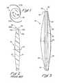
- FIG. 1is a plan view of one form of intraocular lens (IOL) constructed in accordance with the teachings of present invention.
- IOLintraocular lens
- FIG. 2is a cross-sectional view of an optic of a prior art IOL.
- FIG. 3is an elevational view of an optic of an exemplary embodiment of an IOL of the present invention having a medium diopter value.
- FIG. 4is an elevational view of an optic of a further exemplary IOL of the present invention having a small diopter value.
- FIG. 5is an elevational view of an optic of a further exemplary IOL of the present invention having a large diopter value.
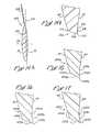
- FIG. 6is an elevational view of a peripheral edge region of the IOL of FIG. 3 showing the paths of a plurality of light rays passing therethrough.
- FIG. 7is a cross-sectional view of a peripheral edge region of an IOL of the present invention having an edge surface that is parallel to the optical axis, an anteriorly-facing edge surface that is not parallel to the optical axis and an anterior JO peripheral land that is perpendicular to the optical axis.
- FIG. 8is a cross-sectional view of a peripheral edge region of an IOL of the present invention having an anteriorly-facing edge surface not parallel to the optical axis and an anterior peripheral land perpendicular to the optical axis.
- FIG. 9is a cross-sectional view of a peripheral edge region of an IOL of the present invention having an anteriorly-facing edge surface that is not parallel to the optical axis and no peripheral land.
- FIG. 10is a cross-sectional view of a peripheral edge region of an IOL of the present invention having an edge surface that is parallel to the optical axis and an anterior peripheral land that is not perpendicular to the optical axis.
- FIG. 11is a cross-sectional view of a peripheral edge region of an IOL of the present invention having an edge surface that is parallel to the optical axis, an anterior peripheral land that is perpendicular to the optical axis, and an anterior peripheral land that is not perpendicular to the optical axis.
- FIG. 12is a cross-sectional view of a peripheral edge region of an IOL of the present invention having a posteriorly-facing edge surface that is not parallel to the optical axis and no peripheral land.
- FIG. 13is a cross-sectional view of a peripheral edge region of an IOL of the present invention having a posteriorly-facing edge surface that is not parallel to the optical axis and an anterior peripheral land that is perpendicular to the optical axis.
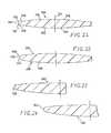
- FIG. 14 ais a radial sectional view of an IOL of the present invention showing a fixation member extending from a peripheral edge.
- FIG. 14 bis an elevational view of a peripheral edge region of the IOL of FIG. 14 a.
- FIGS. 15-17are elevational views of peripheral edge regions of IOLs of the present invention each having an anteriorly-facing edge surface that is not parallel to the optical axis, a rounded transition surface between the edge surface and the anterior face of the IOL, and a posterior peripheral land.
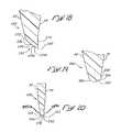
- FIG. 18is an elevational view of a peripheral edge region of an IOL of the present invention having a baffle structure disposed along an anteriorly-facing edge surface.
- FIG. 19is an elevational view of a peripheral edge region of an IOL of the present invention having an anteriorly-facing edge surface and a rounded transition surface between the edge surface and the anterior face of the IOL.
- FIG. 20is an elevational view of a peripheral edge region of an IOL of the present invention having both anteriorly- and posteriorly-facing edge surfaces.
- FIG. 21is a cross-sectional view of the optic of an alternative IOL of the present invention.
- FIG. 22is a cross-sectional view of the optic of an alternate embodiment of an IOL in accordance with the present invention.
- FIG. 23is a partial cross-sectional view of the optic of a further embodiment of an IOL in accordance with the present invention.
- FIG. 24is a partial cross-sectional view of an additional embodiment of an IOL in accordance with the present invention.
- FIG. 25is a partial cross-sectional view of the optic of another embodiment of an IOL in accordance with the present invention.
- FIG. 26is a partial cross-sectional view of the optic of a further alternate embodiment of an IOL in accordance with the present invention.
- FIG. 28is a partial cross-sectional view of the optic of still another embodiment of an IOL in accordance with the present invention.
- FIG. 1shows an IOL 20 which generally comprises an optic 22 and fixation members 24 a and 24 b .
- the optic 22may be considered as effective for focusing light on or near the retina of the eye.
- Optical axis 26passes through the center of optic 22 in a direction generally transverse to the plane of the optic.
- the optic 22is circular in plan and bi-convex approaching the optical axis 26 .
- the optic 22may be constructed of any of the commonly employed materials used for rigid optics, such as polymethylmethacrylate (PMMA), or commonly employed materials used for resiliently deformable optics, such as silicone polymeric materials, acrylic polymeric materials, hydrogel-forming polymeric materials, mixtures thereof and the like.
- PMMApolymethylmethacrylate
- silicone polymeric materialsacrylic polymeric materials
- hydrogel-forming polymeric materialsmixtures thereof and the like.
- fixation members 24 a and 24 b in this embodimentare generally C-shaped and are integral with the optic 22 .
- the IOLs of the present inventionmay consist of one piece, with unitary optic and fixation members, or may be three or more pieces, with two or more fixation members connected to the optic.
- IOL 20can be produced using conventional techniques well-known in the art.
- IOL 20Unless expressly described hereinafter, the general structural characteristics of IOL 20 apply to the other IOLs noted herein.
- FIG. 2illustrates an optic 30 of an IOL of the prior art having an optical axis OA, a convex anterior face AF, a convex posterior face PF, and a peripheral edge 32 .
- the peripheral edge 32is typically circular and has a constant cross-section circumscribing the optic 30 .
- the optic 30 illustratedis of the square-cornered variety which provides some inhibition of cell growth onto the optic 30 , a condition known as posterior capsule opacification (PCO).
- PCOposterior capsule opacification
- the peripheral edge 32comprises an edge surface 34 that is parallel to the optical axis OA, and both anterior and posterior edge corners 36 a , 36 b , respectively.
- anterior and posterior lands 38 a , 38 bextend between the anterior face AF and posterior face PF and respective edge corner 36 a or 36 b . Both the anterior and posterior lands 38 a , 38 b extend substantially perpendicularly with respect to the optical axis OA. Because of the parallel edge surface 34 , the prior art optic 30 does not provide reduced edge glare as do the IOLs in accordance with the present invention.
- anterior and posteriorare used in their conventional sense; anterior refers to the front side of the eye, while posterior refers to the rear side.
- a number of surfaces of the intraocular lens of present inventionare denoted either “anteriorly-facing” or “posteriorly-facing” to indicate their orientation with respect to the optical axis of the lens.
- a surface that is parallel to the optical axisis neither anteriorly-facing or posteriorly-facing.
- a surface that is even slightly angled in one direction or the othercan be identified with either the anterior or posterior side of the lens, depending on which side that surface faces.
- FIG. 3illustrates an optic 40 of an IOL of the present invention having an advantageous peripheral edge 42 .
- the optic 40defines an optical axis OA, a convex anterior face AF, and a convex posterior face PF.
- the peripheral edge 42is desirably circular in shape, and has a constant cross-section circumscribing the optic 40 .
- the peripheral edge 42may not extend completely around the optic 40 , and may be interrupted by alternative peripheral edge configurations, including combinations of peripheral edge configurations in accordance with the present invention.
- the optic 40is shown in elevational view to better illustrate the peripheral edge 42 in relation to the convex anterior face AF and posterior face PF.
- the peripheral edge 42includes a curved or rounded transition surface 44 leading to an anterior peripheral land or region 46 that is desirably linear and substantially perpendicular to the optical axis OA.
- a discontinuous posterior edge corner 50separates the peripheral edge 42 from the posterior face PF, with no peripheral land. The edge corner 50 defines the posterior limit of the peripheral edge 42 .
- the peripheral edge 42further comprises an edge surface 52 that is linear and substantially parallel to the optical axis OA adjacent the posterior edge corner 50 , and an anteriorly-facing edge surface 54 that is linear and non-parallel to the optical axis OA adjacent the rounded transition surface 44 .
- a shallow corner or discontinuity 56separates the parallel edge surface 52 from the non-parallel edge surface 54 .
- discontinuityrefers to a transition between two peripheral edge surfaces that is visible as a corner or peripheral line on the optic.
- all cornersultimately have a radius, but discontinuity in this regard pertains only to a corner that is visible as a discrete line as opposed to a more rounded region.
- “visible” in this regardrefers to visible as seen by the naked eye, or with the assistance of certain low-power magnification devices, such as an ocular.
- Another way to define corners in the presence senseis the intersection between two linear surfaces, at least with respect to the magnification shown in the drawings of the present application.
- Still another way to look at the effect of a discontinuity at the corner of the peripheral edgeis that cell growth from the eye in front of or in back of the optic is more inhibited relative to a substantially identical intraocular lens without the discontinuity.
- edge geometry around the periphery of any particular lens of the present inventionmay not be constant, and the edge surfaces disclosed herein should not be construed as necessarily extending in a constant configuration around the entire periphery of the lens.
- the anterior peripheral land or region 46is shown as being linear and substantially perpendicular to the optical axis OA, other configurations are contemplated.
- the peripheral land 46could be other than linear, i.e., convex or concave with respect to a plane through the medial plane of the optic.
- the peripheral land 46could be angled toward or away from the anterior side.
- there may be more than one surface defining the peripheral land 46such as a curved and a linear surface.
- FIGS. 4 and 5illustrate two further optics 60 a and 60 b that have substantially the same configuration as the optic 40 of FIG. 3 . That is, both optics 60 a and 60 b have an optical axis OA, a convex anterior face AF, a convex posterior face PF, and a peripheral edge 62 a , 62 b , respectively.
- Each peripheral edge 62 a , 62 bcomprises, respectively, a rounded transition surface 64 a , 64 b , and anterior peripheral land 66 a , 66 b that is substantially perpendicular to the optical axis OA, a posterior edge corner 70 a , 70 b , an edge surface 72 a , 72 b that is substantially parallel to the optical axis OA, and an anteriorly-facing edge surface 74 a , 74 b that is non-parallel to the optical axis OA.
- FIGS. 4 and 5Various dimensions for the respective peripheral edges of the exemplary optics shown in FIGS. 3-5 are also given in FIGS. 4 and 5 . That is, the thickness of each peripheral edge is given as t, the thickness of the parallel edge surface is given as A, the angle of the non-parallel edge surface is given as ⁇ , and a radius of curvature of the transition surface is given as R.
- the following tablesprovide exemplary values for these dimensions for the optics 60 a and 60 b of FIGS. 4 and 5 . These dimensions are considered suitable for optics 60 a and 60 b that are made from silicone. It should be noted that the dimensions for the optic 40 of FIG. 3 are desirably approximately equal to those for the optic 60 b of FIG. 5 . It should also be noted that the following dimensions are believed to provide certain benefits as far as reducing glare and PCO in IOLs, although not all the dimensions have been selected for either of those particular purposes. For example, some of the dimensions may be desirable to facilitate manufacturing of the respective IOL.
- Table Iprovides exemplary values for optics that are made from acrylic.
- Table IIprovides exemplary values for the same dimensions as shown in FIGS. 4-5 , but for optics that are made from acrylic.
- the subscript “1”pertains to optics having a diopter value of 10
- the subscript “2”pertains to optics having a diopter value of either 20 or 30.
- the convexity of the various lenses along the optical axis OAincreases with increasing diopter value (the posterior face and especially the anterior face are more highly convex).
- some surgeonsprefer the intraocular lenses to have approximately the same volume or center thickness at the optical axis regardless of diopter power. This permits the surgeon to use the same surgical technique across the diopter range. Therefore, the present invention contemplates varying the overall diameter of the optic for different diopter values. That is, the center thickness of the intraocular lenses for different diopter values remains the same regardless of diameter. Therefore, the diameter of lenses having greater convexity should be reduced to reduce the center thickness, and the diameter of flatter lenses should be increased, both to an intermediate value.
- the diameter of the lower diopter value optic 60 a shown in FIG. 4may be increased so that the center thickness is closer to the intermediate diopter value optic 40 shown in FIG. 3 .
- the diameter of the higher diopter value optic 60 b shown in FIG. 5may be decreased so that the center thickness is closer to the optic 40 shown in FIG. 3 .
- the present inventioncontemplates a set of intraocular lenses having varying diopter values wherein the diameter of the optics varies generally inversely (although not necessarily linearly) with respect to the diopter value.
- a set of intraocular lenses having approximately the same center thicknesscan be provided to the surgeon to help make the implantation procedure more consistent and predictable.
- One example of a set of intraocular lensesmay include the optics shown in FIGS. 3-5 .
- the lower diopter lens 60 a of FIG. 4may have a diameter of approximately 6.25 mm
- the intermediate diopter lens 40 of FIG. 3may have a diameter of 6.0 mm
- the higher diopter lens 60 b of FIG. 5may have a diameter of 5.75 mm.
- an increased diameter for lower diopter lensescorresponds to human physiology. That is, people who require lower diopter lenses typically have larger eyes, while people requiring high diopters tend to have smaller eyes.
- FIG. 6illustrates a section of the peripheral edge 42 of the optic 40 of FIG. 3 with a plurality of discrete light rays 80 a , 80 b , 80 c , entering the peripheral edge from the anterior side.
- the refracted/reflected path of each light ray through the peripheral edge 42is indicated, with the path of each light ray as it exits the peripheral edge 42 indicated as 82 a , 82 b and 82 c.
- FIG. 6thus illustrates the advantageous characteristic of the peripheral edge 42 in diffusing incoming parallel light rays so that the reflected light intensity is reduced. That is, any light that ordinarily would reflect back towards the optical axis at near its original intensity is instead diffused to reduce glare in the IOL.
- the present inventioncontemplates utilizing a curved or rounded transition surface, such as the surface 44 , in combination with one or more planar edge surfaces that are not parallel to the optical axis, such as the edge surface 54 .
- the peripheral edge 42further includes the edge surface 52 that is substantially parallel to the optical axis. It is believed that the combination of the rounded transition surface 44 on the anterior side leading to the anteriorly-facing edge surface 54 substantially reduces glare within the optic 40 .
- FIGS. 7-9each illustrates one half of an optic of an IOL in section having a configuration that reduces glare.
- incoming lightis refracted so as to decrease the probability of light reflecting off the peripheral edge surfaces toward the optical axis relative to conventional lenses.
- incoming lightreflects off of an internal peripheral edge surface at a shallow angle of incidence not toward the optical axis so as to decrease the probability of light reflecting off of other edge surfaces relative to conventional lenses.
- All of the optics disclosed in FIGS. 7-9comprise an optical axis OA, a convex anterior face AF, and a convex posterior face PF.
- An incoming light ray 106is illustrated passing through the peripheral land 104 to reflect off the second edge surface 96 within the optic 90 .
- the resulting reflected ray 108is deflected through the optic 90 so that it misses the first edge surface 94 .
- a substantial portion of the light entering the optic 90 in the region of the peripheral edge 92is reflected at a relatively shallow angle of incidence off of the second edge surface 96 , and is not reflected off the first edge surface 94 toward the optical axis OA.
- the anteriorly-facing second edge surface 96is desirably angled at least about 10° with respect to the optical axis OA.
- FIG. 8illustrates an optic 110 having a peripheral edge 112 comprising a single anteriorly-facing edge surface 114 that is linear and non-parallel with respect to the optical axis OA.
- the optic 110has a single conical anteriorly-facing edge surface 114 .
- a posterior edge corner 116separates the edge surface 114 from the posterior face PF, and an anterior edge corner 118 separates the edge surface 114 from a peripheral land 120 that is substantially perpendicular to the optical axis OA.
- An incoming light ray 122is illustrated striking the peripheral land 120 and passing through the optic 110 .
- the light raymay refract slightly on passage through the optic 110 , as indicated at 124 , but will not reflect off the surface edge 114 . That is, the posterior, edge corner 116 is located farther radially outward from the optical axis OA than the anterior edge corner 118 and a substantial portion of light passing into the region of the peripheral edge 112 simply passes through the material of the optic 110 .
- the anteriorly-facing edge surface 114is desirably angled at least about 5° with respect to the optical axis OA.
- FIG. 9illustrates an optic 130 that is substantially similar to the optic 110 of FIG. 8 , with a peripheral edge 132 defined by a single anteriorly-facing edge surface 134 that is linear and non-parallel with respect to the optical axis OA.
- the optic 130has a single conical anteriorly-facing edge surface 134 .
- a posterior edge corner 136separates the peripheral edge 132 from the posterior face PF.
- An anterior edge corner 138separates the peripheral edge 132 from the anterior face AF, and there is no anterior peripheral land.
- the path of a light ray 140 passing through the region of the peripheral edge 132illustrates the elimination of any reflection off a peripheral edge surface.
- the anteriorly-facing edge surface 134is desirably angled at least about 5° with respect to the optical axis OA.
- FIGS. 10-13illustrate a number of optics of the present invention that are configured to transmit internal light radially outward from their peripheral edges as opposed to reflecting it toward the optical axis. This can be done in a number of ways, all of which result in light hitting the peripheral edge from the interior of the optic at an angle that is less than the critical angle for the refractive index of the lens material.
- each of the optics in FIGS. 10-13includes an optical axis OA, a convex anterior face AF, and a convex posterior face PF.
- FIGS. 10 and 11illustrate two substantially similar optics 150 a , 150 b that will be given corresponding element numbers.
- Each of the optics 150 a , 150 hhas a peripheral edge 152 b , 152 b defined by an edge surface 154 a , 154 b that is linear and substantially parallel to the optical axis OA.
- a posterior edge corner 156 a , 156 bseparates the edge surface 154 a , 154 b from the respective posterior face PF.
- Both optics 150 a , 150 binclude an acute anterior edge corner 158 a , 158 b separating the edge surface 154 a , 154 b from an anterior peripheral land 160 a , 160 b .
- the peripheral lands 160 a , 160 bare shown as linear and non-perpendicular with respect to the optical axis OA, but it should be understood that non-linear lands may perform equally as well, and may further diffuse the incoming light.
- the peripheral land 160 a of the optic 150 a of FIG. 10joins with its anterior face AF at a discontinuity 162 .
- a peripheral land 164 that is linear and substantially perpendicular to the optical axis OAjoins the peripheral land 160 b of the optic 150 b of FIG. 11 to its anterior face AF; that is, there are two peripheral lands 160 b and 164 on the optic 150 b of FIG. 11 .
- Incoming light rays 166 a , 166 bare illustrated in FIGS. 10 and 11 striking the respective peripheral lands 160 a , 160 b and passing through the material of the respective optics 150 a , 150 b toward the edge surfaces 154 a , 154 b . Because of the particular angle of the peripheral lands 160 a , 160 b , the light rays strike the edge surfaces 154 a , 154 b at angles that are less than the critical angle for the refractive index of the lens material.
- the light rayspass through the peripheral edges 152 a , 152 b as indicated by the exit rays 168 a , 168 b .
- the included angles between the edge surfaces 154 a , 154 b and the peripheral lands 160 a , 160 bare shown ⁇ 1 and ⁇ a . These angles are preferably less than 90°, more preferably within the range of about 45° to 88°, and most preferably within the range of about 70° to 88°. Of course, these ranges may differ depending on the refractive index of the material.
- FIGS. 12 and 13illustrate similar optics 170 a , 170 b that each have a peripheral edge 172 a , 172 b defined by a posteriorly-facing edge surface 174 a , 174 b that is linear and non-parallel with respect to the optical axis OA.
- a posterior edge corner 176 a , 176 bseparates the edge surface 174 a , 174 b from the posterior face PF.
- an anterior edge corner 178 aseparates the edge surface 174 a from the anterior face AF, without a peripheral land.
- FIG. 12illustrate similar optics 170 a , 170 b that each have a peripheral edge 172 a , 172 b defined by a posteriorly-facing edge surface 174 a , 174 b that is linear and non-parallel with respect to the optical axis OA.
- a posterior edge corner 176 a , 176 bseparates the edge surface 174 a , 174 b
- an anterior edge corner 178 bseparates the edge surface 174 b from a peripheral land 180 that is linear and substantially perpendicular to the optical axis OA of the optic 170 b .
- the peripheral land 180meets the anterior face AF at a discontinuity 182 .
- the angles of the anterior edge corners 178 a and 17813are indicated at ⁇ 1 and ⁇ 2 .
- the magnitude of the angle ⁇ 1depends both on the convexity of the anterior face AF and the angle of the posteriorly-facing edge surface 174 a with respect to the optical axis OA.
- the anterior face AFmay have widely differing convexities, but desirably the posteriorly-facing edge surface 174 a is at least 2° (clockwise in the drawing) with respect to the optical axis OA. Therefore, the angle ⁇ 1 is preferably less than about 120°, and more preferably are within the range of about 70° to 120°.
- the peripheral land 180is shown as linear and perpendicular with respect to the optical axis OA, but it should be understood that non-linear and non-parallel lands may perform equally as well.
- the posteriorly-facing edge surface 174 bis at least 2° (clockwise in the drawing) with respect to the optical axis OA. Therefore, the angle ⁇ 2 is preferably acute, and more preferably is within the range of about 30° to 88°. Of course, these ranges may differ depending on the refractive index of the material.
- FIGS. 12 and 13illustrate incoming light rays 184 a , 184 b that strike the anterior side of the respective optic 170 a , 170 b adjacent the peripheral edges 172 a , 172 b and subsequently pass through the material of the optic and through the edge surfaces 174 a , 174 b without reflection.
- this phenomenonis caused by the angles at which the light rays strike the edge surfaces 174 a , 174 b , which are lower than the critical angle for the refractive index of the lens material.
- the light rayssimply pass through the peripheral edges 172 a , 172 b without reflecting back towards the optical axis OA.
- FIG. 14 aillustrates a further embodiment of an IOL 200 of the present invention having an optic 202 and a plurality of fixation members 204 extending radially outward therefrom, only one of which is shown.
- FIG. 14 bis an enlargement of a peripheral edge region of the optic 202 .
- the optic 202includes an optical axis OA, a convex anterior face AF, and a convex posterior face PF.
- the optic 202includes a peripheral edge 206 defined by an anteriorly-facing edge surface 208 that is linear and non-parallel with respect to the optical axis OA.
- a curved or rounded transition surface 210smoothly blends the linear edge surface 208 to the convex anterior face AF.
- An acute posterior edge corner 212separates the edge surface 208 from a peripheral land 214 that is linear and substantially perpendicular to the optical axis OA.
- the peripheral land 214joins with the convex posterior face PF at a discontinuity 216 .
- FIG. 14 aillustrates a plane 218 coincident with the circular posterior edge corner 212 . This plane represents a separation line between two mold halves used to form the optic 202 . In this manner, the acute peripheral edge corner 212 can be easily formed between the mold halves.
- FIGS. 14 a and 14 bincorporates a combination of several advantageous features previously described. That is, the rounded transition surface 210 tends to diffuse light rays entering from the anterior side, as described above with respect to the embodiment of FIGS. 3-5 .
- the edge surface 208is angled in such a manner that some of the light passing through the transition surface 210 will not even strike it, and the light that does will be reflected at a relatively shallow angle of incidence that reduces glare.
- FIGS. 15-17illustrate the peripheral edges of three optics 220 a , 220 b , 220 c having similar shapes.
- the optic 220 a of FIG. 15has a peripheral edge defined by an anteriorly-facing surface 222 a that is linear and non-parallel with respect to the optical axis, an acute posterior edge corner 224 a , and a rounded anterior transition surface 226 a blending with the anterior face AF.
- a peripheral land 228 athat is generally perpendicular with respect to the optical axis extends between the posterior face PF and the edge corner 224 a , and joins with the posterior face PF at a discontinuity 230 a .
- the included angle between the surface 222 a and the peripheral land 228 ais relatively small, and the rounded transition surface 226 a protrudes slightly outward from the surface 222 a.
- the peripheral edge of the optic 220 b shown in FIG. 16also includes—an anteriorly-facing surface 222 b that is linear and non-parallel with respect to the optical axis, an acute posterior edge corner 224 b , and a rounded anterior transition surface 226 b blending with the anterior face AF.
- a peripheral land 228 b that is not perpendicular to the optical axisextends between the posterior face PF and the edge corner 224 b .
- the peripheral land 228 bjoins with the posterior face PF at a discontinuity 230 b .
- the included angle between the surface 222 b and the peripheral land 228 bis slightly larger than that shown in FIG. 15 , primarily because the surface 222 b has a shallower angle with respect to the optical axis than the surface 222 a.
- the peripheral edge of the optic 220 c shown in FIG. 17also includes—an anteriorly-facing surface 222 e that is linear and non-parallel with respect to the optical axis, an acute posterior edge corner 224 c , and a rounded anterior transition surface 226 c blending with the anterior face AF.
- a peripheral land 228 c that is not perpendicular to the optical axisextends between the posterior face PF and the edge corner 224 c .
- the peripheral land 228 cjoins with the posterior face PF at a discontinuity 230 c .
- the optic 220 cis fairly similar to the optic 220 b , but has a slightly less convex posterior face PF.
- FIG. 18illustrates the peripheral edge of an optic 240 having a saw-tooth or baffled edge surface 242 .
- the edge surface 242is generally aligned to face the anterior side of the optic 240 and includes multiple tooth facets or surfaces 244 a and 244 b defining peaks 246 and troughs 248 .
- Each tooth surface 244 ais desirably parallel to the other surfaces on the same side of each tooth, as is each tooth surface 244 b with respect to the others on the other side of each tooth.
- the peripheral edge of the optic 240further includes a posterior edge corner 250 and a rounded transition surface 252 blending into the anterior face AF.
- a peripheral land 254that is generally perpendicular to the optical axis extends between the posterior face PF and the edge corner 250 .
- edge surface 242is angled so as to be non-parallel with respect to the optical axis, and thus some of the light rays internal to the optic 240 will not even strike this edge surface to further reduce glare.
- FIG. 19An optic 260 that includes a linear posteriorly-facing edge surface 262 is seen in FIG. 19 .
- the peripheral edge of the optic 260comprises the edge surface 262 , a rounded transition surface 264 blending to the anterior face AF, and a peripheral edge corner 266 adjacent a short peripheral land 268 .
- the advantages of the posteriorly-facing edge surface 262were described previously with respect to FIGS. 12 and 13 , and primarily involved light being transmitted through the edge surface as opposed to being internally reflected off of it. Of course, light that is transmitted through the edge surface 262 as opposed to being reflected off of it cannot contribute to glare.
- the rounded transition surface 264helps to diffuse light rays striking the peripheral edge, thus further reducing glare.
- FIG. 20illustrates an optic 280 having both an anterior edge corner 282 and posterior edge corner 284 .
- a posteriorly-facing edge surface 286extends from the anterior edge corner 282 to an apex 288
- an anteriorly-facing edge surface 290extends between the apex and the posterior edge corner 284 .
- the apex 288defines the midpoint of a groove, and the resulting configuration in cross-section is something like a forked-tongue.
- a pair of peripheral lands 292 a , 292 bextends between the edge corners 282 , 284 and the respective anterior and posterior faces of the optic 280 .
- the peripheral lands 292 a , 292 bare desirably perpendicular to the optical axis.
- the provision of linear edge surfaces that are non-parallel with respect to the optical axishelps reduce glare within the optic 280 .
- the relatively sharp edge corners 282 , 284helps reduce PCO by inhibiting cell growth on both the anterior and posterior sides of the optic 280 .
- FIG. 21Another embodiment of the invention seen in FIG. 21 has an optic 300 with an anterior face 302 , a posterior face 304 , an anterior peripheral region 306 , a posterior peripheral region 308 and a peripheral edge surface 310 .
- the peripheral edge surface 310has a continuously curved, concave configuration, for example, in cross-section.
- the peripheral edge surface 310intersects anterior peripheral region 306 at anterior peripheral corner edge 312 at an angle of about 70°. Corner edge 312 is at a discontinuity between anterior face 302 (anterior peripheral region 306 ) and peripheral edge surface 310 , and circumscribes optical axis 314 .
- Peripheral edge surface 310intersects posterior peripheral region 308 at posterior peripheral corner edge 316 at an angle of about 70° Corner edge 316 is at a discontinuity between posterior face 304 (posterior peripheral region 308 ) and peripheral edge surface 310 , and circumscribes optical axis 314 .
- the anterior and posterior peripheral regions 306 and 308extend radially inwardly, for example, for a distance of about 0.1 mm to about 1.0 mm or more (about 0.5 mm as shown in FIG. 21 ), from the peripheral edge surface 310 , and peripheral corner edge 312 and 316 respectively, and are substantially planar, more particularly, substantially perpendicular to the optical axis 314 of optic 300 .
- Anterior face 302includes an additional anterior region 318 which is convex, not planar.
- Posterior face 304includes an additional posterior region 320 which also is convex, not planar.
- the dimension of optic 300 between anterior face 302 and posterior face 304 at the peripheral regions 306 and 308is smaller than the same dimension at the optical axis 314 .
- an IOL having the optic 300 in the capsular bag of an eyeeffectively inhibits or retards cell migration or growth, for example, epithelial cell migration or growth, from the eye onto and/or over the anterior and, posterior faces 302 and 304 of optic 300 .
- a reduced amount of edge glareis obtained with an IOL having the optic 300 implanted in the capsular bag of the eye.
- an IOL having the optic 300provides for inhibition of cell migration or growth onto and/or over the optic 300 because of the sharp or abrupt peripheral corner edges 312 and 316 .
- the cells from the eyehave a reduced tendency to grow onto and/or over the anterior face 302 and posterior face 304 relative to a substantially identical IOL without such peripheral corner edge.
- the reduced glare obtained using an IOL having the optic 300results from the curved configuration of the peripheral edge surface 310 .
- an IOL having the optic 300 including the substantially continuously curved peripheral edge surface 310provides reduced glare relative to a substantially similar IOL having a peripheral edge surface which is substantially parallel, for example, in cross-section, to the optical axis of the IOL.
- FIG. 22illustrates an alternate embodiment of an IOL in accordance with the present invention.
- This IOLhas an optic shown generally at 330 .
- optic 330is structured and functions similarly to optic 300 .
- anterior face 332 and posterior face 334can be independently provided to address the needs of any given specific application including the following factors; the vision correction or corrections desired, the size of optic 330 , the size of the eye in which an IOL having optic 330 is to be placed and the like factors.
- Optic 330inhibits or retards cell migration or growth and provides a reduced amount of edge glare as does the optic 300 , described above.
- FIG. 23illustrates a further embodiment of an IOL in accordance with the present invention.
- This IOLhas an optic shown generally at 350 .
- optic 350is structured and functions similarly to optic 330 .
- FIG. 24illustrates an additional embodiment of the present invention.
- the IOL illustrated in FIG. 24has an optic shown generally at 360 .
- optic 360is structured and functions similarly to optic 330 .
- the primary difference between optic 360 and optic 330relates to the configuration of peripheral edge surface 362 .
- the curvature of peripheral edge surface 362varies substantially continuously (in a manner which is substantially the reverse of the curvature of peripheral edge surface 352 of optic 350 ) while the curvature of edge 336 is a substantially constant concave are (in cross-section).
- the peripheral edge surface 362 of optic 360is effective in reducing the glare caused by the presence of optic 360 in the eye relative to the glare obtained with IOL 30 of FIG. 2 in the eye.
- FIG. 25illustrates an additional embodiment of an IOL in accordance with the present invention. Except as expressly described herein, this IOL, having an optic shown generally at 370 is structured and functions similarly to optic 330 .
- peripheral edge surface 372includes a first portion 374 which is concave relative to the optical axis 376 of optic 370 .
- Peripheral edge surface 372also includes a second portion 378 which is convex relative to the optical axis 376 of optic 370 .
- the curvature of the peripheral edge surface of the present IOLsfor example, peripheral edge surface 372 of optic 370 , can be relatively complex.
- Peripheral edge surface 372is effective to provide reduced glare in the eye relative to IOL 30 of FIG. 2 .
- peripheral edge surface 372intersects anterior face 380 at anterior peripheral corner edge 382 at an angle of about 90°.
- peripheral edge surface 372intersects posterior peripheral region 384 at posterior peripheral corner edge 386 at an angle of about 90°.
- Optic 370is effective in inhibiting or retarding cell migration or growth from the eye onto or over the optic 370 .
- FIG. 26illustrates a further alternate embodiment of an IOL in accordance with the present invention.
- This IOLhas an optic shown generally at 400 .
- optic 400is structured and functions substantially similarly to optic 330 .
- peripheral edge surface 402has a continuously curved configuration somewhat similar to peripheral edge surface 372 of optic 370 .
- the anterior face 404intersects peripheral edge surface 402 on a curve (that is on a continuity not at a discontinuity). In other words, the intersection of anterior face 404 and peripheral edge surface 402 is smooth or continuous, not sharp or discontinuous.
- Optic 400is effective in reducing the amount of glare obtained with optic 400 in the eye relative to IOL 30 of FIG. 2 in the eye. Also, optic 370 is effective in retarding or inhibiting migration from the eye onto and/or over cell growth or migration from the eye onto and/or over the posterior face 406 of optic 400 .
- FIG. 27illustrates a still further embodiment of an IOL in accordance with the present invention. Except as expressly described herein, this IOL, having an optic shown generally at 410 is structured and functions similarly to optic 330 .
- peripheral edge surface 412is convex relative to the optical axis 416 of optic 410 .
- Peripheral edge surface 412does not intersect anterior face 418 at a sharp or discontinuous corner edge, but does intersect posterior face 414 at an obtuse angle at posterior peripheral corner 420 .
- Posterior face 414includes a peripheral region 422 which is substantially perpendicular to optical axis 416 .
- Anterior face 418includes a peripheral region 424 which is roughened to be at least partially opaque to the transmission of light. The combination of the convex peripheral edge surface 412 and the at least partially opaque peripheral region 424 is particularly effective in reducing glare, for example, from corner 420 , obtained with an IOL having optic 410 in the eye.
- FIG. 28illustrates still another embodiment of an IOL in accordance with the present invention.
- This IOLhas an optic shown generally at 440 .
- optic 440is structured and functions substantially similarly to optic 330 .
- Peripheral edge surface 442includes a first portion 448 which is convex relative to optic axis 450 of optic 440 .
- Peripheral edge surface 442also includes a second portion 452 which transitions from first portion 448 and intersects posterior face 446 at corner 454 .
- Peripheral edge surface 442does not intersect anterior face 444 at a sharp or discontinuance corner edge.
- Posterior face 446includes a peripheral region 456 which is substantially perpendicular to optical axis 450 .
- Anterior face 444includes the peripheral region 458 which is roughened to be at least partially opaque to the transmission of light. Region 460 of peripheral edge surface 442 and region 462 of posterior face 446 are also roughened to be at least partially opaque to the transmission of light.
- the combination of the peripheral edge surface 442 and the at least partially opaque regions 458 , 460 , 462is particularly effective in reducing glare, for example, from corner edge 454 , obtained with optic 440 in the eye.
- the edges and surfaces near the edgesmay be “textured” or frosted to cause scatter of light impinging on the peripheral region. Such scattering helps reduce edge glare.
- use of texture in combination with various edge geometriesmay help reduce PCO.
- Various texturing regimensmay be used, as described in U.S. Pat. No. 5,693,094, entitled IOL for Reducing Secondary Opacification, hereby expressly incorporated by reference.
- IOLs made of siliconedesirably include texturing/frosting on at least one edge surface as well as on a peripheral region of the posterior face, or intermediate land.
- Acrylic IOLsdesirably include texturing/frosting on at least one edge surface, and preferably on an edge surface that is parallel to the optical axis.
- the intraocular lenses of the present inventionmay be manufactured using a variety of techniques, including injection molding, compression molding, lathing, and milling. Those of skill in the art will understand how to form the mold dies, or program the cutting tools to shape the lenses in accordance with present invention. Importantly, care must be taken to avoid rounding the various corners or discontinuities for the particular optic during the polishing process. Therefore, the corners must be masked or otherwise protected while the lens is being polished. Alternatively, the unmasked lens may be polished and then the various edge surfaces re-cut to insure sharp corners.
- the design of the fixation members 24 a , 24 bmay play an important role in reducing the risk of PCO for any particular lens. That is, the fixation members 24 a , 24 b must be designed such that during capsular contraction, there is enough axial movement and accompanying bias of the lens against the posterior capsule to seal the capsule around the posterior edge corners of the lens.
- a variety of fixation members 24 a , 24 bare known in the art that can provide the required posterior bias to the lens.
- fixation members 24 a , 24 bmay vary depending on the overall lens diameter, the diameter of the optic, the angle of the fixation member, the stiffness of the fixation member material, the gauge of the fixation member, the geometry of the fixation member, and the way in which the fixation member is attached to the lens.
- the present inventionvery effectively provides IOLs which inhibit cell growth or migration, in particular epithelial cell growth or migration from a capsular bag, onto and/or over the IOL optics.
- the IOLsproduce reduced glare, in particular edge glare, relative to a lens having a peripheral edge which is substantially parallel, in cross-section, to the optical axis of the IOL optic.
Landscapes
- Health & Medical Sciences (AREA)
- Ophthalmology & Optometry (AREA)
- Biomedical Technology (AREA)
- Heart & Thoracic Surgery (AREA)
- Cardiology (AREA)
- Oral & Maxillofacial Surgery (AREA)
- Transplantation (AREA)
- Engineering & Computer Science (AREA)
- Veterinary Medicine (AREA)
- Public Health (AREA)
- Vascular Medicine (AREA)
- Life Sciences & Earth Sciences (AREA)
- Animal Behavior & Ethology (AREA)
- General Health & Medical Sciences (AREA)
- Electromagnetism (AREA)
- Physics & Mathematics (AREA)
- Prostheses (AREA)
Abstract
Description
| TABLE I |
| EXEMPLARY DIMENSIONS FOR SILICONE IOLs |
| T1(in) | t2(in) | A1(in) | A2(in) | θ1 | θ2 | R1(in) | R2(in) |
| .023-.027 | .012-.014 | .002-.007 | .002-.007 | 13-17° | 13-17° | .001-.003 | .004-.006 |
| TABLE II |
| EXEMPLARY DIMENSIONS FOR ACRYLIC IOLs |
| t1(in) | t2(in) | A1(in) | A2(in) | θ1 | θ2 | R1(in) | R2(in) |
| .015-.019 | .013-.017 | .002-.007 | .002-.007 | 13-17° | 13-17° | .004-.008 | .004-.008 |
Claims (12)
Priority Applications (1)
| Application Number | Priority Date | Filing Date | Title |
|---|---|---|---|
| US14/181,146US9949822B2 (en) | 1998-05-29 | 2014-02-14 | Intraocular lens for inhibiting cell growth and reducing glare |
Applications Claiming Priority (7)
| Application Number | Priority Date | Filing Date | Title |
|---|---|---|---|
| US09/086,882US6162249A (en) | 1998-05-29 | 1998-05-29 | IOI for inhibiting cell growth and reducing glare |
| US44871399A | 1999-11-24 | 1999-11-24 | |
| US09/507,602US6468306B1 (en) | 1998-05-29 | 2000-02-18 | IOL for inhibiting cell growth and reducing glare |
| US10/245,290US20030058060A1 (en) | 2001-09-21 | 2002-09-18 | Noise reduction high frequency circuit |
| US10/284,802US20030130733A1 (en) | 1998-05-29 | 2002-10-30 | Novel intraocular lens for reducing glare |
| US11/552,429US20070106378A1 (en) | 1998-05-29 | 2006-10-24 | Intraocular lens for inhibiting cell growth and reducing glare |
| US14/181,146US9949822B2 (en) | 1998-05-29 | 2014-02-14 | Intraocular lens for inhibiting cell growth and reducing glare |
Related Parent Applications (1)
| Application Number | Title | Priority Date | Filing Date |
|---|---|---|---|
| US11/552,429ContinuationUS20070106378A1 (en) | 1998-05-29 | 2006-10-24 | Intraocular lens for inhibiting cell growth and reducing glare |
Publications (2)
| Publication Number | Publication Date |
|---|---|
| US20140163674A1 US20140163674A1 (en) | 2014-06-12 |
| US9949822B2true US9949822B2 (en) | 2018-04-24 |
Family
ID=26775258
Family Applications (7)
| Application Number | Title | Priority Date | Filing Date |
|---|---|---|---|
| US09/507,602Expired - LifetimeUS6468306B1 (en) | 1998-05-29 | 2000-02-18 | IOL for inhibiting cell growth and reducing glare |
| US10/213,308AbandonedUS20030055498A1 (en) | 1998-05-29 | 2002-08-06 | IOL for inhibiting cell growth and reducing glare |
| US10/229,250AbandonedUS20030060879A1 (en) | 1998-05-29 | 2002-08-27 | IOL for inhibiting cell growth and reducing glare |
| US10/245,920Expired - Fee RelatedUS7252683B2 (en) | 1998-05-29 | 2002-09-18 | Intraocular lens for inhibiting cell growth and reducing glare |
| US10/284,802AbandonedUS20030130733A1 (en) | 1998-05-29 | 2002-10-30 | Novel intraocular lens for reducing glare |
| US11/552,429AbandonedUS20070106378A1 (en) | 1998-05-29 | 2006-10-24 | Intraocular lens for inhibiting cell growth and reducing glare |
| US14/181,146Expired - Fee RelatedUS9949822B2 (en) | 1998-05-29 | 2014-02-14 | Intraocular lens for inhibiting cell growth and reducing glare |
Family Applications Before (6)
| Application Number | Title | Priority Date | Filing Date |
|---|---|---|---|
| US09/507,602Expired - LifetimeUS6468306B1 (en) | 1998-05-29 | 2000-02-18 | IOL for inhibiting cell growth and reducing glare |
| US10/213,308AbandonedUS20030055498A1 (en) | 1998-05-29 | 2002-08-06 | IOL for inhibiting cell growth and reducing glare |
| US10/229,250AbandonedUS20030060879A1 (en) | 1998-05-29 | 2002-08-27 | IOL for inhibiting cell growth and reducing glare |
| US10/245,920Expired - Fee RelatedUS7252683B2 (en) | 1998-05-29 | 2002-09-18 | Intraocular lens for inhibiting cell growth and reducing glare |
| US10/284,802AbandonedUS20030130733A1 (en) | 1998-05-29 | 2002-10-30 | Novel intraocular lens for reducing glare |
| US11/552,429AbandonedUS20070106378A1 (en) | 1998-05-29 | 2006-10-24 | Intraocular lens for inhibiting cell growth and reducing glare |
Country Status (1)
| Country | Link |
|---|---|
| US (7) | US6468306B1 (en) |
Families Citing this family (59)
| Publication number | Priority date | Publication date | Assignee | Title |
|---|---|---|---|---|
| US5693094A (en)* | 1995-05-09 | 1997-12-02 | Allergan | IOL for reducing secondary opacification |
| US6468306B1 (en) | 1998-05-29 | 2002-10-22 | Advanced Medical Optics, Inc | IOL for inhibiting cell growth and reducing glare |
| US20060238702A1 (en) | 1999-04-30 | 2006-10-26 | Advanced Medical Optics, Inc. | Ophthalmic lens combinations |
| FR2795944B1 (en)* | 1999-07-08 | 2001-11-02 | Corneal Ind | INTRAOCULAR IMPLANT |
| US7204849B2 (en)* | 2001-03-15 | 2007-04-17 | Valdemar Portney | Narrow profile intraocular lens |
| US6558419B1 (en)* | 2001-11-08 | 2003-05-06 | Bausch & Lomb Incorporated | Intraocular lens |
| US20030120342A1 (en)* | 2001-12-21 | 2003-06-26 | Green George F. | Intraocular lens |
| US7326246B2 (en)* | 2002-01-14 | 2008-02-05 | Advanced Medical Optics, Inc. | Accommodating intraocular lens with elongated suspension structure |
| US7763069B2 (en) | 2002-01-14 | 2010-07-27 | Abbott Medical Optics Inc. | Accommodating intraocular lens with outer support structure |
| US6648741B2 (en)* | 2002-03-14 | 2003-11-18 | Advanced Medical Optics, Inc. | Apparatus for protecting the edge geometry of an intraocular lens during glass bead polishing process |
| WO2003077803A1 (en)* | 2002-03-18 | 2003-09-25 | Hanita Lenses Ltd. | Sharp angle intraocular lens optic |
| US7160324B2 (en) | 2002-05-17 | 2007-01-09 | Amo Groningen, B.V. | Method in eye surgery |
| GB0217606D0 (en)* | 2002-07-30 | 2002-09-11 | Rayner Intraocular Lenses Ltd | Intraocular lens |
| US7662180B2 (en) | 2002-12-05 | 2010-02-16 | Abbott Medical Optics Inc. | Accommodating intraocular lens and method of manufacture thereof |
| US20040188872A1 (en)* | 2003-03-31 | 2004-09-30 | Jani Dharmendra M. | Method for fabricating intraocular lens with peripheral sharp edge |
| JP4974527B2 (en)* | 2003-04-28 | 2012-07-11 | Hoya株式会社 | Integrated intraocular lens and manufacturing method thereof |
| US20050033422A1 (en) | 2003-08-08 | 2005-02-10 | Advanced Medical Optics, Inc. | Glare reducing rough surfaces |
| US7217289B2 (en)* | 2003-09-12 | 2007-05-15 | Minas Theodore Coronco | Treatment of photic disturbances in the eye |
| EP1667610A1 (en)* | 2003-09-30 | 2006-06-14 | Bausch & Lomb Incorporated | Intraocular lens for inhibiting pco and aco |
| US7144423B2 (en)* | 2003-11-12 | 2006-12-05 | Mcdonald Marguerite B | Intraocular multifocal lens |
| CA2548735C (en) | 2003-12-09 | 2012-11-13 | Advanced Medical Optics, Inc. | Foldable intraocular lens and method of making |
| US7615073B2 (en)* | 2003-12-09 | 2009-11-10 | Advanced Medical Optics, Inc. | Foldable intraocular lens and method of making |
| US7813836B2 (en)* | 2003-12-09 | 2010-10-12 | Intouch Technologies, Inc. | Protocol for a remotely controlled videoconferencing robot |
| US20050131535A1 (en) | 2003-12-15 | 2005-06-16 | Randall Woods | Intraocular lens implant having posterior bendable optic |
| FR2865381B1 (en)* | 2004-01-28 | 2006-04-28 | Corneal Ind | INTRAOCULAR IMPLANT WITH FLEXIBLE OPTICS |
| US20050187621A1 (en)* | 2004-02-24 | 2005-08-25 | Brady Daniel G. | Foldable unitary intraocular lens |
| US7569073B2 (en)* | 2004-12-29 | 2009-08-04 | Bausch & Lomb Incorporated | Small incision intraocular lens with anti-PCO feature |
| US20070067031A1 (en)* | 2005-09-22 | 2007-03-22 | Alcon, Inc. | Intraocular lens |
| US9636213B2 (en) | 2005-09-30 | 2017-05-02 | Abbott Medical Optics Inc. | Deformable intraocular lenses and lens systems |
| US8709078B1 (en)* | 2011-08-03 | 2014-04-29 | Lockheed Martin Corporation | Ocular implant with substantially constant retinal spacing for transmission of nerve-stimulation light |
| US20070244560A1 (en)* | 2006-04-12 | 2007-10-18 | Alexei Ossipov | Intraocular lens with distortion free valve |
| US8568478B2 (en) | 2006-09-21 | 2013-10-29 | Abbott Medical Optics Inc. | Intraocular lenses for managing glare, adhesion, and cell migration |
| US20080077238A1 (en) | 2006-09-21 | 2008-03-27 | Advanced Medical Optics, Inc. | Intraocular lenses for managing glare, adhesion, and cell migration |
| US20080161914A1 (en) | 2006-12-29 | 2008-07-03 | Advanced Medical Optics, Inc. | Pre-stressed haptic for accommodating intraocular lens |
| US20080269890A1 (en)* | 2007-04-30 | 2008-10-30 | Alcon Universal Ltd. | Intraocular lens with peripheral region designed to reduce negative dysphotopsia |
| US20080269886A1 (en)* | 2007-04-30 | 2008-10-30 | Simpson Michael J | IOL Peripheral Surface Designs to Reduce Negative Dysphotopsia |
| US20080269885A1 (en)* | 2007-04-30 | 2008-10-30 | Simpson Michael J | IOL Peripheral Surface Designs to Reduce Negative Dysphotopsia |
| US20080269882A1 (en)* | 2007-04-30 | 2008-10-30 | Alcon Universal Ltd. | Intraocular lens with asymmetric optics |
| US20080269891A1 (en)* | 2007-04-30 | 2008-10-30 | Alcon, Inc. | Intraocular lens with edge modification |
| US8034108B2 (en) | 2008-03-28 | 2011-10-11 | Abbott Medical Optics Inc. | Intraocular lens having a haptic that includes a cap |
| WO2010151691A2 (en) | 2009-06-26 | 2010-12-29 | Abbott Medical Optics Inc. | Accommodating intraocular lenses |
| CA2770074C (en) | 2009-08-03 | 2017-09-05 | Abbott Medical Optics Inc. | Intraocular lens for providing accomodative vision |
| RU2012127318A (en)* | 2009-12-01 | 2014-01-20 | Алькон Рисерч, Лтд. | INTRAOCULAR LENS WITH EDGE EXECUTED WITH THE POSSIBILITY OF REDUCING THE DISTURBANCE OF THE REAR CAPSULE |
| NL2006307C2 (en) | 2011-02-28 | 2012-08-29 | Oculentis B V | Ophthalmic lens having enhanced optical blending zone. |
| EP2790565B1 (en)* | 2011-03-25 | 2018-10-31 | EOS Holdings, LLC | Ophthalmic inspection lens |
| EP2805694B1 (en) | 2012-01-19 | 2019-06-26 | Eyebright Medical Technology (Beijing) Co., Ltd. | Posterior chamber-type intraocular lens |
| US9084674B2 (en) | 2012-05-02 | 2015-07-21 | Abbott Medical Optics Inc. | Intraocular lens with shape changing capability to provide enhanced accomodation and visual acuity |
| AU2013282349B2 (en)* | 2012-06-29 | 2017-09-14 | Johnson & Johnson Surgical Vision, Inc. | Reduced glare intraocular lens |
| AU2013356553B2 (en)* | 2012-12-06 | 2017-10-19 | Alcon Inc. | Edge design for reducing photic effects in intraocular lenses |
| US9805508B1 (en)* | 2013-04-01 | 2017-10-31 | Marvell International Ltd | Active augmented reality display enhancement |
| WO2016058051A1 (en) | 2014-10-15 | 2016-04-21 | Minas Theodore Coroneo | An improved lens design |
| CN106901871B (en)* | 2015-12-23 | 2021-08-24 | 爱博诺德(北京)医疗科技股份有限公司 | Intraocular lens with one or more additional portions |
| EP3681438A1 (en) | 2017-09-11 | 2020-07-22 | AMO Groningen B.V. | Methods and apparatuses to increase intraocular lenses positional stability |
| TW201927263A (en)* | 2017-12-18 | 2019-07-16 | 瑞士商諾華公司 | Intraocular lens platform having improved haptic force distribution |
| TW202002915A (en)* | 2018-04-06 | 2020-01-16 | 瑞士商愛爾康股份有限公司 | Hybrid optical edge for an intraocular lens (IOL) |
| WO2020083828A1 (en)* | 2018-10-24 | 2020-04-30 | Amo Groningen B.V. | Intraocular lenses for reducing the risk of posterior capsule opacification |
| JP7550760B2 (en)* | 2018-12-21 | 2024-09-13 | アルコン インコーポレイティド | Multi-curvature edges for ophthalmic lenses |
| CN115515531A (en)* | 2020-03-11 | 2022-12-23 | 华柏恩视觉研究中心有限公司 | Intraocular lens for reducing peripheral pseudoglare phantom |
| US12064338B2 (en) | 2020-09-17 | 2024-08-20 | Desikan Raiguru Kadambi | Implantable accommodating intraocular lenses and related methods |
Citations (245)
| Publication number | Priority date | Publication date | Assignee | Title |
|---|---|---|---|---|
| US2043840A (en) | 1934-06-23 | 1936-06-09 | Optical Res Corp | Ophthalmic lens |
| US2110724A (en) | 1936-08-20 | 1938-03-08 | Goettel Peter | Waxing device |
| SU142482A1 (en) | 1961-04-05 | 1961-11-30 | В.Н. Киселев-Цецхладзе | Fish protection device mounted on the suction pipe of the pumping station |
| US3034403A (en) | 1959-04-03 | 1962-05-15 | Neefe Hamilton Res Company | Contact lens of apparent variable light absorption |
| US3284406A (en) | 1963-12-18 | 1966-11-08 | Dow Corning | Organosiloxane encapsulating resins |
| US3341490A (en) | 1964-08-13 | 1967-09-12 | Dow Corning | Blends of two polysiloxane copolymers with silica |
| US3454332A (en) | 1966-11-03 | 1969-07-08 | Robert Siegel | Corneal plastic contact lens with colored peripheral zone |
| US3457214A (en) | 1965-12-15 | 1969-07-22 | Gen Electric | Low temperature vulcanizing composition and article made therefrom |
| US3578850A (en) | 1970-02-11 | 1971-05-18 | Alan H Grant | Anti-flare contact lens |
| US3992355A (en) | 1974-01-25 | 1976-11-16 | Shinetsu Chemical Company | Heat-curable organopolysiloxane compositions |
| US3996187A (en) | 1975-04-29 | 1976-12-07 | American Optical Corporation | Optically clear filled silicone elastomers |
| US3996189A (en) | 1975-04-29 | 1976-12-07 | American Optical Corporation | Optically clear filled silicone elastomers |
| US3996935A (en) | 1969-02-14 | 1976-12-14 | Surgical Design Corporation | Surgical-type method for removing material |
| US4056855A (en) | 1976-04-07 | 1977-11-08 | Charles Kelman | Intraocular lens and method of implanting same |
| US4092743A (en) | 1976-10-04 | 1978-06-06 | Kelman Charles D | Intraocular lenses |
| US4168547A (en) | 1977-04-01 | 1979-09-25 | Medicinska Akademia | Anterior-chamber lens-carrier |
| US4172297A (en) | 1976-02-24 | 1979-10-30 | Inprohold Establishment | Artificial implant lens |
| US4173798A (en) | 1978-05-04 | 1979-11-13 | Welsh Robert C | Intra-ocular lens |
| US4189546A (en) | 1977-07-25 | 1980-02-19 | Bausch & Lomb Incorporated | Polysiloxane shaped article for use in biomedical applications |
| US4370760A (en) | 1981-03-25 | 1983-02-01 | Kelman Charles D | Anterior chamber intraocular lens |
| US4377873A (en) | 1980-10-30 | 1983-03-29 | Reichert Jr Henry L | Intraocular lens |
| US4380643A (en) | 1981-08-24 | 1983-04-19 | Asahi Glass Company, Ltd. | Benzotriazole compound and homopolymer or copolymers thereof |
| WO1983001566A1 (en) | 1981-10-30 | 1983-05-11 | Koester, Charles, J. | Intraocular lens for patients with central retinal degeneration |
| GB2111835A (en) | 1981-12-17 | 1983-07-13 | Frederick Thomason Feaster | Intraocular lens |
| GB2114315A (en) | 1982-02-05 | 1983-08-17 | Mazzocco Thomas R | Deformable intraocular lens structures and methods and devices for implantation |
| US4402579A (en) | 1981-07-29 | 1983-09-06 | Lynell Medical Technology Inc. | Contact-lens construction |
| US4412359A (en) | 1982-04-26 | 1983-11-01 | Myers William D | Posterior chamber lens implant |
| US4418165A (en) | 1980-06-03 | 1983-11-29 | Dow Corning Corporation | Optically clear silicone compositions curable to elastomers |
| US4423809A (en) | 1982-02-05 | 1984-01-03 | Staar Surgical Company, Inc. | Packaging system for intraocular lens structures |
| US4424597A (en) | 1981-05-13 | 1984-01-10 | Inprohold Establishment | Posterior chamber implant lens |
| EP0099641A2 (en) | 1982-06-28 | 1984-02-01 | Kelman, Charles D. | Intraocular lens |
| US4429421A (en) | 1982-02-03 | 1984-02-07 | Levy Chauncey F | Method of implanting an intraocular lens |
| GB2124500A (en) | 1982-07-22 | 1984-02-22 | Mazzocco Thomas R | Improved fixation system for intraocular lens structures |
| US4435050A (en) | 1980-02-26 | 1984-03-06 | Stanley Poler | Contact lens assembly with haptic and method for making the same |
| US4435856A (en) | 1982-04-14 | 1984-03-13 | Esperance Francis A L | Bifocal intraocular lens structure and spectacle actuation frame |
| US4435866A (en) | 1982-03-04 | 1984-03-13 | Royden Brown | Pollen trap for beehives with dual entranceways |
| US4439873A (en) | 1980-02-26 | 1984-04-03 | Stanley Poler | Intra-ocular lens construction |
| US4440918A (en) | 1982-01-18 | 1984-04-03 | Minnesota Mining And Manufacturing Company | Contact lens containing a fluorinated telechelic polyether |
| US4449267A (en) | 1982-05-26 | 1984-05-22 | Siemion Edward D | Floor seal strip |
| US4449257A (en) | 1982-05-03 | 1984-05-22 | Barnes-Hind/Hydrocurve, Inc. | Intraocular lens and method of retaining in place |
| US4450593A (en) | 1981-11-09 | 1984-05-29 | Lynell Medical Technology Inc. | Intraocular and contact lens construction |
| US4451938A (en) | 1982-09-24 | 1984-06-05 | Kelman Charles D | Intraocular lens and method of positioning the same in an eye |
| EP0110537A2 (en) | 1982-12-02 | 1984-06-13 | Dow Corning Corporation | Surface treatment of inorganic fillers |
| DE3246306A1 (en) | 1982-12-14 | 1984-06-14 | Titmus Eurocon Kontaktlinsen Gmbh & Co Kg, 8750 Aschaffenburg | Bifocal lens of bivisual type |
| USRE31626E (en) | 1978-12-01 | 1984-07-10 | Intraocular lens | |
| US4468820A (en) | 1982-05-10 | 1984-09-04 | Precision-Cosmet Co., Inc. | Haptic attachment for intraocular lenses |
| US4470159A (en) | 1982-03-03 | 1984-09-11 | Peyman Gholam A | Keratoprosthesis |
| US4494254A (en) | 1982-05-03 | 1985-01-22 | Osvaldo Lopez | Intraocular lens |
| US4495361A (en) | 1983-04-29 | 1985-01-22 | Bausch & Lomb Incorporated | Polysiloxane composition with improved surface wetting characteristics and biomedical devices made thereof |
| EP0134489A1 (en) | 1983-07-20 | 1985-03-20 | McTigue, John | Intraocular lens |
| US4521273A (en) | 1980-02-26 | 1985-06-04 | Stanley Poler | Method of making a lens and haptic assembly |
| US4525346A (en) | 1981-09-28 | 1985-06-25 | Alcon Laboratories, Inc. | Aqueous antimicrobial ophthalmic solutions |
| US4532267A (en) | 1984-02-15 | 1985-07-30 | Board Of Regents, University Of Washington | Vision correction lens made from an aminopolysaccharide compound or an ether or ester thereof |
| US4535141A (en) | 1984-03-23 | 1985-08-13 | Dow Corning Corporation | Liquid curable polyorganosiloxane compositions |
| US4535488A (en) | 1982-09-30 | 1985-08-20 | Haddad Heskel M | Anterior-posterior chamber intraocular lens |
| US4537943A (en) | 1983-07-21 | 1985-08-27 | Innovative Surgical Products, Inc. | Correction of defects in the eye and compositions therefor |
| US4541206A (en) | 1983-10-17 | 1985-09-17 | Iolab Corp. | Fixture for holding an optical lens during tumbling |
| US4542542A (en) | 1983-07-21 | 1985-09-24 | Innovative Surgical Products, Inc. | Correction of defects in the eye and compositions therefor |
| US4543398A (en) | 1983-04-28 | 1985-09-24 | Minnesota Mining And Manufacturing Company | Ophthalmic devices fabricated from urethane acrylates of polysiloxane alcohols |
| US4562600A (en) | 1983-10-18 | 1986-01-07 | Stephen P. Ginsberg | Intraocular lens |
| US4570626A (en) | 1984-01-20 | 1986-02-18 | Norris John L | Corneal light shield |
| US4571040A (en) | 1980-02-26 | 1986-02-18 | Lynell Medical Technology, Inc. | Contact lens and haptic |
| US4575373A (en) | 1984-11-02 | 1986-03-11 | Johnson Don R | Laser adjustable intraocular lens and method of altering lens power |
| US4576607A (en) | 1984-07-13 | 1986-03-18 | Kelman Charles D | Intraocular lenses |
| US4580371A (en) | 1983-10-17 | 1986-04-08 | Iolab Corporation | Method for tumble grinding optical lens edge |
| US4585455A (en) | 1983-10-28 | 1986-04-29 | Ioptex Inc. | Intraocular lens with iris spacer mechanism |
| US4585457A (en) | 1985-05-16 | 1986-04-29 | Kalb Irvin M | Inflatable intraocular lens |
| US4588406A (en) | 1985-08-15 | 1986-05-13 | Fedorov Svjatoslav N | Intraocular lens |
| US4597388A (en) | 1983-12-15 | 1986-07-01 | Trutek Research, Inc. | Apparatus for removing cataracts |
| EP0186634A2 (en) | 1984-12-03 | 1986-07-02 | Precision-Cosmet Co., Inc. | Intraocular lens with foldable sides |
| US4601722A (en) | 1984-10-30 | 1986-07-22 | Kelman Charles D | Intraocular lens |
| US4601545A (en) | 1984-05-16 | 1986-07-22 | Kern Seymour P | Variable power lens system |
| US4605409A (en) | 1984-05-21 | 1986-08-12 | Kelman Charles D | Intraocular lens with miniature optic having expandable and contractible glare-reducing means |
| US4608050A (en) | 1983-07-21 | 1986-08-26 | Innovative Surgical Products, Inc. | Correction of defects in the eye and compositions therefor |
| GB2171912A (en) | 1985-03-05 | 1986-09-10 | Charles William Simcoe | Hinged intraocular lens |
| EP0195881A1 (en) | 1985-03-27 | 1986-10-01 | Pharmacia Ab | Intraocular lens |
| US4615702A (en) | 1984-09-10 | 1986-10-07 | Koziol Jeffrey E | Intraocular lens and method of forming the lens |
| US4619662A (en) | 1985-04-19 | 1986-10-28 | Juergens Jr Albert M | Intraocular lens |
| US4619657A (en) | 1984-09-07 | 1986-10-28 | Keates Richard H | Flexible intraocular lens holder |
| EP0202049A1 (en) | 1985-04-30 | 1986-11-20 | Baxter Travenol Laboratories, Inc. | Bi-concave small incision intraocular lens |
| US4624670A (en) | 1983-04-08 | 1986-11-25 | Bechert Ii Charles H | Intraocular lens |
| US4629460A (en) | 1984-06-25 | 1986-12-16 | Dyer Robert L | Intraocular lens |
| US4632844A (en) | 1984-02-04 | 1986-12-30 | Japan Synthetic Rubber Co., Ltd. | Optical product having a thin film on the surface |
| US4636210A (en) | 1985-12-09 | 1987-01-13 | Hoffer Kenneth J | Multi-part intraocular lens and method of implanting it in an eye |
| US4647282A (en) | 1985-08-27 | 1987-03-03 | Moskovsky Nauchno-Issledovatelsky Institut Mikrokhirurgii Glaza | Material for ocular prosthetics |
| US4652622A (en) | 1983-04-29 | 1987-03-24 | Bausch & Lomb Incorporated | Polysiloxane composition with improved surface wetting characteristics and biomedical devices made thereof |
| EP0215468A2 (en) | 1985-09-14 | 1987-03-25 | Fromberg, Gunther, Dr. | Artificial lens for implantation in the eye |
| US4657546A (en) | 1983-07-08 | 1987-04-14 | Shearing Steven P | Intraocular lens |
| GB2181355A (en) | 1985-10-15 | 1987-04-23 | Storz Instr Co | Lens implant |
| US4661108A (en) | 1985-07-03 | 1987-04-28 | Surgidev Corporation | Intraocular lens |
| US4664667A (en) | 1982-06-28 | 1987-05-12 | Kelman Charles D | Deformable intraocular lens |
| US4666445A (en) | 1985-10-01 | 1987-05-19 | Tillay Michael J | Intraocular lens with shape memory alloy haptic/optic and method of use |
| US4673406A (en) | 1984-10-29 | 1987-06-16 | Inprohold Establishment | One-piece implantation lens |
| EP0226400A2 (en) | 1985-12-04 | 1987-06-24 | Allergan, Inc | Intraocular lens |
| US4676793A (en) | 1984-05-17 | 1987-06-30 | Bechert Ii Charles H | Intraocular lens |
| US4676791A (en) | 1985-08-01 | 1987-06-30 | Surgidev Corporation | Intraocular lens and method for making same |
| US4678469A (en) | 1986-10-20 | 1987-07-07 | Kelman Charles D | Intraocular lens with glare-inhibiting closure, the method of inhibiting glare, and the closure for same |
| US4681102A (en) | 1985-09-11 | 1987-07-21 | Bartell Michael T | Apparatus and method for insertion of an intra-ocular lens |
| US4685922A (en) | 1986-06-25 | 1987-08-11 | Peyman Gholam A | Alterable refractive power intraocular lenses |
| EP0242159A1 (en) | 1986-04-14 | 1987-10-21 | Iolab Corporation | Reduced glare intraocular lens |
| US4702244A (en) | 1982-02-05 | 1987-10-27 | Staar Surgical Company | Surgical device for implantation of a deformable intraocular lens |
| US4704123A (en) | 1986-07-02 | 1987-11-03 | Iolab Corporation | Soft intraocular lens |
| US4704124A (en) | 1985-01-22 | 1987-11-03 | Shearing Steven P | Intraocular lens |
| EP0246754A1 (en) | 1986-04-21 | 1987-11-25 | Kelman, Charles D. | Intraocular lens having glare-inhibiting means |
| US4710195A (en) | 1986-04-18 | 1987-12-01 | Giovinazzo Vincent J | Posterior chamber intraocular lens |
| US4710194A (en) | 1986-10-20 | 1987-12-01 | Kelman Charles D | Intraocular lens with optic of expandable hydrophilic material |
| US4711638A (en) | 1986-05-12 | 1987-12-08 | Lindstrom Richard L | Intraocular lens |
| US4713072A (en) | 1985-11-22 | 1987-12-15 | Swedish Graft Technique Ab | Implant lens and method and apparatus for its production |
| US4715373A (en) | 1985-09-27 | 1987-12-29 | Mazzocco Thomas R | Devices for implantation of deformable intraocular lens structures |
| US4718906A (en) | 1986-03-11 | 1988-01-12 | Mackool Richard J | Intraocular lens |
| US4720286A (en) | 1984-07-20 | 1988-01-19 | Bailey Kelvin E | Multifocus intraocular lens |
| US4725278A (en) | 1985-01-22 | 1988-02-16 | Shearing Steven P | Intraocular lens |
| US4731079A (en) | 1986-11-26 | 1988-03-15 | Kingston Technologies, Inc. | Intraocular lenses |
| US4731078A (en) | 1985-08-21 | 1988-03-15 | Kingston Technologies Limited Partnership | Intraocular lens |
| US4737558A (en) | 1985-11-25 | 1988-04-12 | Alcon Laboratories, Inc. | Siloxane copolymers for ophthalmic applications |
| US4738680A (en) | 1986-07-03 | 1988-04-19 | Herman Wesley K | Laser edge lens |
| US4743254A (en) | 1985-01-31 | 1988-05-10 | American Hospital Supply Company | Small incision intraocular lens |
| EP0268569A1 (en) | 1986-11-03 | 1988-05-25 | Precision-Cosmet Co., Inc. | Foldable intraocular lens |
| US4753653A (en) | 1986-11-03 | 1988-06-28 | Precision-Cosmet Co., Inc. | Foldable bifocal intraocular lens |
| US4759763A (en) | 1986-11-03 | 1988-07-26 | Precision-Cosmet Co., Inc. | Foldable intraocular lens |
| US4764169A (en) | 1986-12-04 | 1988-08-16 | Grendahl Dennis T | Intraocular lens |
| US4769034A (en) | 1987-03-26 | 1988-09-06 | Poley Brooks J | Folded intraocular lens, method of implanting folded intraocular lens |
| US4769035A (en) | 1987-06-02 | 1988-09-06 | Kelman Charles D | Artificial lens and the method for implanting such lens |
| US4781717A (en) | 1985-07-24 | 1988-11-01 | Grendahl Dennis T | Intraocular lens |
| US4781718A (en) | 1987-10-09 | 1988-11-01 | Lindstrom Richard L | Intraocular lens |
| US4785047A (en) | 1987-07-30 | 1988-11-15 | Dow Corning Corporation | Method for preparing clear polyorganosiloxane elastomers |
| US4790846A (en) | 1985-12-09 | 1988-12-13 | Allergan Pharmaceuticals, Inc. | Haptic to optic attachment for a soft IOL |
| US4806382A (en) | 1987-04-10 | 1989-02-21 | University Of Florida | Ocular implants and methods for their manufacture |
| US4808181A (en) | 1987-08-07 | 1989-02-28 | Kelman Charles D | Intraocular lens having roughened surface area |
| US4834754A (en) | 1983-07-08 | 1989-05-30 | Shearing Steven P | Intraocular lens |
| US4840627A (en) | 1986-04-08 | 1989-06-20 | Michael Blumenthal | Artificial eye lens and method of transplanting same |
| US4842782A (en) | 1986-10-14 | 1989-06-27 | Allergan, Inc. | Manufacture of ophthalmic lenses by excimer laser |
| EP0326373A1 (en) | 1988-01-26 | 1989-08-02 | Nestle S.A. | Intraocular Lens |
| US4856234A (en) | 1988-02-26 | 1989-08-15 | Research Machine Center, Inc. | Optical lens manufacturing apparatus and method |
| US4863466A (en) | 1986-04-01 | 1989-09-05 | Schlegel Hans Joachim | Intra-ocular implant lens |
| US4863465A (en) | 1987-02-10 | 1989-09-05 | Kelman Charles D | Intraocular lens with multiple-fulcrum haptic |
| US4868251A (en) | 1986-12-24 | 1989-09-19 | Allergan, Inc. | Ultraviolet light absorbing silicone compositions |
| US4868151A (en) | 1986-06-25 | 1989-09-19 | Jujo Paper Co., Ltd. | Heat-sensitive recording material |
| EP0335312A2 (en) | 1988-03-28 | 1989-10-04 | Hoya Corporation | Intraocular lens |
| WO1989009578A1 (en) | 1988-04-11 | 1989-10-19 | Albrektsson Bjoern | Knee-joint prosthesis |
| US4878912A (en) | 1988-11-09 | 1989-11-07 | Castleman Lawrence D | Foldable intraocular disc lens |
| US4878910A (en) | 1988-06-13 | 1989-11-07 | Koziol Jeffrey E | Intraocular lens assembly |
| US4880427A (en) | 1984-06-25 | 1989-11-14 | Anis Aziz Y | Flexible posterior chamber lens |
| US4882398A (en) | 1988-08-26 | 1989-11-21 | Dow Corning Corporation | Optically clear reinforced organosiloxane compositions |
| SU1537244A1 (en) | 1987-07-14 | 1990-01-23 | Всесоюзный Научно-Исследовательский Институт Глазных Болезней | Artificial eye lens |
| WO1990001306A1 (en) | 1988-08-10 | 1990-02-22 | Gunter Fromberg | Artificial intraocular lens |
| US4911714A (en) | 1987-03-26 | 1990-03-27 | Poley Brooks J | Foldable intraocular lens and improved fold retaining means |
| US4917680A (en) | 1988-06-30 | 1990-04-17 | Poley Brooks J | Folded intraocular lens with endless band retainer |
| CA1273144A (en) | 1985-05-07 | 1990-08-21 | Takafumi Uemiya | Cross-linked optical siloxane polymer |
| US4963148A (en) | 1988-04-11 | 1990-10-16 | Ceskoslvnska Akademie Ved | Intraocular optical system |
| US4978352A (en) | 1989-06-07 | 1990-12-18 | Fedorov Svjatoslav N | Process for producing collagen-based cross-linked biopolymer, an implant from said biopolymer, method for producing said implant, and method for hermetization of corneal or scleral wounds involved in eye injuries, using said implant |
| EP0404478A1 (en) | 1989-06-19 | 1990-12-27 | Ioptex Research Inc. | Single piece ovoid introcular lenses with haptics |
| JPH0323857A (en) | 1989-06-22 | 1991-01-31 | Menikon:Kk | Intraocular lens |
| US4990159A (en) | 1988-12-02 | 1991-02-05 | Kraff Manus C | Intraocular lens apparatus with haptics of varying cross-sectional areas |
| US5002571A (en) | 1989-02-06 | 1991-03-26 | Donnell Jr Francis E O | Intraocular lens implant and method of locating and adhering within the posterior chamber |
| EP0419740A1 (en) | 1989-09-27 | 1991-04-03 | HANITA LENSES (a Limited Partnership) | Negative-power intraocular lens |
| US5011494A (en) | 1988-09-16 | 1991-04-30 | Clemson University | Soft tissue implant with micron-scale surface texture to optimize anchorage |
| FR2655842A1 (en) | 1989-12-20 | 1991-06-21 | Maigret Yves | Ocular implant with variable index gradient and a method for its manufacture |
| US5041134A (en) | 1989-08-11 | 1991-08-20 | Donnell Francis E O | Intraocular lens assembly |
| US5053171A (en) | 1986-10-14 | 1991-10-01 | Allergan, Inc. | Manufacture of ophthalmic lenses by excimer laser |
| US5054905A (en) | 1987-11-12 | 1991-10-08 | Cohen Allen L | Progressive intensity phase bifocal |
| US5061840A (en) | 1986-10-14 | 1991-10-29 | Allergan, Inc. | Manufacture of ophthalmic lenses by excimer laser |
| EP0457553A2 (en) | 1990-05-14 | 1991-11-21 | Iolab Corporation | Multifocal multizone diffractive ophthalmic lenses |
| EP0458508A2 (en) | 1990-05-14 | 1991-11-27 | Iolab Corporation | A tuned fresnel lens for multifocal intraocular applications including small incision surgeries |
| EP0458608A1 (en) | 1990-05-22 | 1991-11-27 | BICC Public Limited Company | Multi-part optical fibre connectors |
| US5074875A (en) | 1981-10-30 | 1991-12-24 | Anthony Donn | Intraocular-external lens combination system and method of using same |
| US5074876A (en) | 1987-12-04 | 1991-12-24 | Kelman Charles D | Two piece intraocular lens |
| US5076684A (en) | 1988-04-01 | 1991-12-31 | Minnesota Mining And Manufacturing Company | Multi-focal diffractive ophthalmic lenses |
| US5078740A (en) | 1990-04-02 | 1992-01-07 | Walman Gerald B | Intraocular lens |
| US5089023A (en) | 1990-03-22 | 1992-02-18 | Massachusetts Institute Of Technology | Diffractive/refractive lens implant |
| FR2666735A1 (en) | 1990-09-13 | 1992-03-20 | Klw | Intraocular implant with internal cavity |
| US5108428A (en) | 1988-03-02 | 1992-04-28 | Minnesota Mining And Manufacturing Company | Corneal implants and manufacture and use thereof |
| FR2668922A1 (en) | 1990-11-14 | 1992-05-15 | Franceschi Francois | CRYSTALLINE IMPLANT OF POSTERIOR CHAMBER. |
| US5133751A (en) | 1991-05-20 | 1992-07-28 | Jon Bayers | Intraocular lens |
| US5133749A (en) | 1991-05-13 | 1992-07-28 | Nordan Lee T | Centrating haptics |
| WO1992014421A1 (en) | 1991-02-21 | 1992-09-03 | Grendahl Dennis T | Halo-reducing ophthalmic lens for small incision implant surgery |
| US5147395A (en) | 1991-07-16 | 1992-09-15 | Allergan Inc. | Small incision endocapsulator IOL |
| US5147394A (en) | 1987-10-09 | 1992-09-15 | Siepser Steven B | High refractive index polymeric compositions suitable for use as expansile hydrogel intraocular lenses |
| WO1992015260A1 (en) | 1991-03-01 | 1992-09-17 | Arnott Eric J | Intraocular lens with tapered holding loops |
| EP0507292A1 (en) | 1991-04-04 | 1992-10-07 | Menicon Co., Ltd. | Device for inhibiting aftercataract |
| US5171320A (en) | 1990-11-30 | 1992-12-15 | Menicon Co., Ltd. | Intraocular lens having annular groove formed in its peripheral portion |
| US5179262A (en) | 1986-10-14 | 1993-01-12 | Allergan, Inc. | Manufacture of ophthalmic lenses by excimer laser |
| US5180390A (en) | 1991-07-30 | 1993-01-19 | Drews Robert C | Intraocular lens with reinforcing element |
| US5192318A (en) | 1986-06-05 | 1993-03-09 | Schneider Richard T | One-piece bifocal intraocular lens construction |
| US5197981A (en) | 1992-04-23 | 1993-03-30 | Alcon Surgical, Inc. | Intraocular lens having haptic of specific curvature and proportion |
| US5201763A (en) | 1992-02-28 | 1993-04-13 | Allergan, Inc. | Thin intraocular lens |
| US5203789A (en) | 1991-11-12 | 1993-04-20 | Henry H. McDonald | Foldable plastic optical lens with reduced thickness light blocking segments |
| US5203790A (en) | 1991-11-12 | 1993-04-20 | Henry H. McDonald | Foldable plastic optical lens with reduced thickness light blocking segments, and anchoring means |
| WO1993009732A1 (en) | 1991-11-14 | 1993-05-27 | Stanley Poler | Secondary eye growth impeding device and method |
| US5217491A (en) | 1990-12-27 | 1993-06-08 | American Cyanamid Company | Composite intraocular lens |
| JPH05146461A (en) | 1991-05-13 | 1993-06-15 | Ioptex Res Inc | Variable elastic intraocular lens |
| US5236970A (en) | 1987-02-05 | 1993-08-17 | Allergan, Inc. | Optically clear reinforced silicone elastomers of high optical refractive index and improved mechanical properties for use in intraocular lenses |
| EP0556040A1 (en) | 1992-02-12 | 1993-08-18 | Iolab Corporation | Haptic attachment for soft intraocular lens |
| EP0566461A1 (en) | 1992-04-14 | 1993-10-20 | Corneal | Intraocular implant for capsular bag |
| EP0579528A1 (en) | 1992-07-16 | 1994-01-19 | Corneal | Soft intra-ocular implant lens |
| US5281294A (en) | 1990-04-17 | 1994-01-25 | Pilkington Diffractive Lenses Limited | Manufacture of visual lenses |
| US5300117A (en) | 1990-09-04 | 1994-04-05 | Laboratories Domilens | Intraocular implant for correction of myopia |
| EP0599457A1 (en) | 1992-09-28 | 1994-06-01 | Iolab Corporation | Ophthalmic lens with reduced edge glare |
| JPH06218001A (en) | 1993-01-29 | 1994-08-09 | Hoya Corp | One piece intraocular implanted lens |
| US5366501A (en) | 1993-05-12 | 1994-11-22 | Langerman David W | Intraocular lens with dual 360 degree haptics |
| US5376115A (en) | 1993-08-02 | 1994-12-27 | Pharmacia Ab | Intraocular lens with vaulting haptic |
| WO1995006446A2 (en) | 1993-08-27 | 1995-03-09 | Cumming J Stuart | Accommodating intraocular lens |
| US5405385A (en) | 1992-04-02 | 1995-04-11 | Clemson University | Intraocular lens with integrated means of fixation |
| US5405386A (en) | 1993-07-09 | 1995-04-11 | Kabi Pharmacia Ophthalmics, Inc. | Intraocular lens with improved cylindrical haptic |
| US5429838A (en) | 1992-10-07 | 1995-07-04 | Pharmacia Ab | Method for the production of intraocular lenses |
| EP0668061A1 (en) | 1994-02-17 | 1995-08-23 | Iolab Corporation | Opthalmic lens with reduced edge glare and method of making opthalmic |
| US5476513A (en) | 1992-02-28 | 1995-12-19 | Allergan, Inc. | Intraocular lens |
| JPH08503506A (en) | 1992-11-09 | 1996-04-16 | アラーガン、インコーポレイテッド | Polymer composition and intraocular lens made therefrom |
| US5549670A (en) | 1995-05-09 | 1996-08-27 | Allergan, Inc. | IOL for reducing secondary opacification |
| WO1996025962A1 (en) | 1995-02-23 | 1996-08-29 | Hoya Corporation | Soft intraocular lens |
| JPH08308921A (en) | 1995-05-24 | 1996-11-26 | Hoya Corp | Soft intraocular lens |
| US5578078A (en) | 1993-07-15 | 1996-11-26 | Canon Staar Co., Inc. | Deformable intraocular lens |
| US5593438A (en) | 1995-01-20 | 1997-01-14 | Akhavi; David S. | Intraocular lens with metallic coatings for preventing secondary cataracts |
| US5674283A (en) | 1994-12-01 | 1997-10-07 | Stoy; Vladimir A. | Implantable ophthalmic lens, a method of manufacturing same and a mold for carrying out said method |
| US5693094A (en) | 1995-05-09 | 1997-12-02 | Allergan | IOL for reducing secondary opacification |
| US5693074A (en) | 1993-12-06 | 1997-12-02 | Pacesetter Ab | Cardiac electrotherapy device for cardiac contraction measurement |
| JPH10211A (en) | 1996-06-18 | 1998-01-06 | Okifumi Nishi | Intraocular lens |
| US5713956A (en) | 1991-04-10 | 1998-02-03 | F.C.I. (France Chirurgie Instrumentation) | Microporous support for a keratoprosthesis |
| US5716403A (en) | 1995-12-06 | 1998-02-10 | Alcon Laboratories, Inc. | Single piece foldable intraocular lens |
| US5725811A (en) | 1994-06-27 | 1998-03-10 | Chiron Vision Corporation | IOL tumbling process |
| WO1998016161A1 (en) | 1996-10-11 | 1998-04-23 | Transvascular, Inc. | Methods and apparatus for bypassing arterial obstructions and/or performing other transvascular procedures |
| US5755786A (en) | 1992-09-28 | 1998-05-26 | Iolab Corporation | Ophthalmic lens with reduced edge glare |
| US5961370A (en) | 1997-05-08 | 1999-10-05 | Chiron Vision Corporation | Intraocular lens tumbling process using coated beads |
| WO1999062435A1 (en) | 1998-05-29 | 1999-12-09 | Allergan Sales, Inc. | Iol for inhibiting cell growth and reducing glare |
| US6010391A (en) | 1996-11-01 | 2000-01-04 | Alcon Laboratories, Inc. | Cryogenic polishing method for soft acrylic articles |
| US6027531A (en) | 1997-10-14 | 2000-02-22 | Tassignon; Marie-Joseb. R. | Intraocular lens and method for preventing secondary opacification |
| US6051025A (en) | 1996-03-14 | 2000-04-18 | Corneal Laboratoires | Flexible intraocular implant and set of such implants |
| US6129759A (en) | 1997-12-10 | 2000-10-10 | Staar Surgical Company, Inc. | Frosted haptic intraocular lens |
| WO2000066042A1 (en) | 1999-04-29 | 2000-11-09 | Bausch & Lomb Surgical, Inc. | Intraocular lenses |
| US6158802A (en) | 1997-11-13 | 2000-12-12 | Honda Giken Kogyo Kabushiki Kaisha | Switch mounting structure in a vehicle |
| US6264693B1 (en) | 1998-12-11 | 2001-07-24 | Bausch & Lomb Surgical, Inc. | Air abrasive texturing process for intraocular implants |
| US6280471B1 (en) | 1999-09-16 | 2001-08-28 | Gholam A. Peyman | Glare-free intraocular lens and method for using the same |
| US20020028330A1 (en) | 2000-09-06 | 2002-03-07 | Alcon Universal Ltd. | Switchable tackiness coating compositions for ophthalmic implants |
| US20020045938A1 (en) | 1992-02-28 | 2002-04-18 | Brady Daniel G | Intraocular lens |
| US6406739B1 (en) | 2000-01-12 | 2002-06-18 | Alcon Universal Ltd. | Coating compositions and methods for reducing edge glare in implantable ophthalmic lenses |
| US20020095211A1 (en) | 1995-05-09 | 2002-07-18 | Craig Young | IOL for reducing secondary opacification |
| US6425917B1 (en) | 2000-05-12 | 2002-07-30 | Tekia | Phakic iol film frame |
| US6432246B1 (en) | 1988-10-26 | 2002-08-13 | Pharmacia & Upjohn Company | Fabrication of an intraocular lens |
| US6468306B1 (en) | 1998-05-29 | 2002-10-22 | Advanced Medical Optics, Inc | IOL for inhibiting cell growth and reducing glare |
| WO2003015669A1 (en) | 2001-08-21 | 2003-02-27 | Nulens Ltd. | Accommodating lens assembly |
| US6648741B2 (en) | 2002-03-14 | 2003-11-18 | Advanced Medical Optics, Inc. | Apparatus for protecting the edge geometry of an intraocular lens during glass bead polishing process |
| US6790873B2 (en) | 2001-06-25 | 2004-09-14 | Menicon Co., Ltd. | Ocular lens and process for its production |
| US6884262B2 (en) | 1998-05-29 | 2005-04-26 | Advanced Medical Optics, Inc. | Enhanced intraocular lens for reducing glare |
| US20050177230A1 (en) | 1996-08-27 | 2005-08-11 | Craig Young | IOL for reducing secondary opacification |
| EP1595881A1 (en) | 2004-05-12 | 2005-11-16 | Pfizer Limited | Tetrahydronaphthyridine derivates useful as histamine H3 receptor ligands |
Family Cites Families (4)
| Publication number | Priority date | Publication date | Assignee | Title |
|---|---|---|---|---|
| KR900700061A (en) | 1988-04-15 | 1990-08-11 | 티. 쉬네이더 리차드 | Single piece bifocal lens |
| FR2661816A1 (en) | 1990-05-14 | 1991-11-15 | Arneodo Jacques | Artificial crystalline lens comprising means promoting implantation in order to ensure imperviousness and prevent the migration of the aqueous humor towards the rear |
| PL170815B1 (en) | 1991-06-24 | 1997-01-31 | Gillette Co | Method of making a safety-razor blade and safety-razor blade as such |
| FR2735680B1 (en)* | 1995-06-22 | 1998-01-02 | W K Et Associes | INTRAOCULAR IMPLANT DEVICE FOR CORRECTING OCULAR ANISOTROPY |
- 2000
- 2000-02-18USUS09/507,602patent/US6468306B1/ennot_activeExpired - Lifetime
- 2002
- 2002-08-06USUS10/213,308patent/US20030055498A1/ennot_activeAbandoned
- 2002-08-27USUS10/229,250patent/US20030060879A1/ennot_activeAbandoned
- 2002-09-18USUS10/245,920patent/US7252683B2/ennot_activeExpired - Fee Related
- 2002-10-30USUS10/284,802patent/US20030130733A1/ennot_activeAbandoned
- 2006
- 2006-10-24USUS11/552,429patent/US20070106378A1/ennot_activeAbandoned
- 2014
- 2014-02-14USUS14/181,146patent/US9949822B2/ennot_activeExpired - Fee Related
Patent Citations (270)
| Publication number | Priority date | Publication date | Assignee | Title |
|---|---|---|---|---|
| US2043840A (en) | 1934-06-23 | 1936-06-09 | Optical Res Corp | Ophthalmic lens |
| US2110724A (en) | 1936-08-20 | 1938-03-08 | Goettel Peter | Waxing device |
| US3034403A (en) | 1959-04-03 | 1962-05-15 | Neefe Hamilton Res Company | Contact lens of apparent variable light absorption |
| SU142482A1 (en) | 1961-04-05 | 1961-11-30 | В.Н. Киселев-Цецхладзе | Fish protection device mounted on the suction pipe of the pumping station |
| US3284406A (en) | 1963-12-18 | 1966-11-08 | Dow Corning | Organosiloxane encapsulating resins |
| US3341490A (en) | 1964-08-13 | 1967-09-12 | Dow Corning | Blends of two polysiloxane copolymers with silica |
| US3457214A (en) | 1965-12-15 | 1969-07-22 | Gen Electric | Low temperature vulcanizing composition and article made therefrom |
| US3454332A (en) | 1966-11-03 | 1969-07-08 | Robert Siegel | Corneal plastic contact lens with colored peripheral zone |
| US3996935A (en) | 1969-02-14 | 1976-12-14 | Surgical Design Corporation | Surgical-type method for removing material |
| US3578850A (en) | 1970-02-11 | 1971-05-18 | Alan H Grant | Anti-flare contact lens |
| US3992355A (en) | 1974-01-25 | 1976-11-16 | Shinetsu Chemical Company | Heat-curable organopolysiloxane compositions |
| US3996187A (en) | 1975-04-29 | 1976-12-07 | American Optical Corporation | Optically clear filled silicone elastomers |
| US3996189A (en) | 1975-04-29 | 1976-12-07 | American Optical Corporation | Optically clear filled silicone elastomers |
| US4172297A (en) | 1976-02-24 | 1979-10-30 | Inprohold Establishment | Artificial implant lens |
| US4056855A (en) | 1976-04-07 | 1977-11-08 | Charles Kelman | Intraocular lens and method of implanting same |
| US4092743A (en) | 1976-10-04 | 1978-06-06 | Kelman Charles D | Intraocular lenses |
| US4168547A (en) | 1977-04-01 | 1979-09-25 | Medicinska Akademia | Anterior-chamber lens-carrier |
| US4189546A (en) | 1977-07-25 | 1980-02-19 | Bausch & Lomb Incorporated | Polysiloxane shaped article for use in biomedical applications |
| US4173798A (en) | 1978-05-04 | 1979-11-13 | Welsh Robert C | Intra-ocular lens |
| USRE31626E (en) | 1978-12-01 | 1984-07-10 | Intraocular lens | |
| US4571040A (en) | 1980-02-26 | 1986-02-18 | Lynell Medical Technology, Inc. | Contact lens and haptic |
| US4521273A (en) | 1980-02-26 | 1985-06-04 | Stanley Poler | Method of making a lens and haptic assembly |
| US4439873A (en) | 1980-02-26 | 1984-04-03 | Stanley Poler | Intra-ocular lens construction |
| US4435050A (en) | 1980-02-26 | 1984-03-06 | Stanley Poler | Contact lens assembly with haptic and method for making the same |
| US4418165A (en) | 1980-06-03 | 1983-11-29 | Dow Corning Corporation | Optically clear silicone compositions curable to elastomers |
| US4377873A (en) | 1980-10-30 | 1983-03-29 | Reichert Jr Henry L | Intraocular lens |
| US4370760A (en) | 1981-03-25 | 1983-02-01 | Kelman Charles D | Anterior chamber intraocular lens |
| US4424597A (en) | 1981-05-13 | 1984-01-10 | Inprohold Establishment | Posterior chamber implant lens |
| US4402579A (en) | 1981-07-29 | 1983-09-06 | Lynell Medical Technology Inc. | Contact-lens construction |
| US4380643A (en) | 1981-08-24 | 1983-04-19 | Asahi Glass Company, Ltd. | Benzotriazole compound and homopolymer or copolymers thereof |
| US4525346A (en) | 1981-09-28 | 1985-06-25 | Alcon Laboratories, Inc. | Aqueous antimicrobial ophthalmic solutions |
| WO1983001566A1 (en) | 1981-10-30 | 1983-05-11 | Koester, Charles, J. | Intraocular lens for patients with central retinal degeneration |
| US5074875A (en) | 1981-10-30 | 1991-12-24 | Anthony Donn | Intraocular-external lens combination system and method of using same |
| US4450593A (en) | 1981-11-09 | 1984-05-29 | Lynell Medical Technology Inc. | Intraocular and contact lens construction |
| US4418431A (en) | 1981-12-17 | 1983-12-06 | Feaster Fred T | Intraocular lens |
| GB2111835A (en) | 1981-12-17 | 1983-07-13 | Frederick Thomason Feaster | Intraocular lens |
| US4440918A (en) | 1982-01-18 | 1984-04-03 | Minnesota Mining And Manufacturing Company | Contact lens containing a fluorinated telechelic polyether |
| US4429421A (en) | 1982-02-03 | 1984-02-07 | Levy Chauncey F | Method of implanting an intraocular lens |
| US4702244A (en) | 1982-02-05 | 1987-10-27 | Staar Surgical Company | Surgical device for implantation of a deformable intraocular lens |
| US4423809A (en) | 1982-02-05 | 1984-01-03 | Staar Surgical Company, Inc. | Packaging system for intraocular lens structures |
| US4573998A (en) | 1982-02-05 | 1986-03-04 | Staar Surgical Co. | Methods for implantation of deformable intraocular lenses |
| GB2114315A (en) | 1982-02-05 | 1983-08-17 | Mazzocco Thomas R | Deformable intraocular lens structures and methods and devices for implantation |
| US4470159A (en) | 1982-03-03 | 1984-09-11 | Peyman Gholam A | Keratoprosthesis |
| US4435866A (en) | 1982-03-04 | 1984-03-13 | Royden Brown | Pollen trap for beehives with dual entranceways |
| US4435856A (en) | 1982-04-14 | 1984-03-13 | Esperance Francis A L | Bifocal intraocular lens structure and spectacle actuation frame |
| US4412359A (en) | 1982-04-26 | 1983-11-01 | Myers William D | Posterior chamber lens implant |
| US4449257A (en) | 1982-05-03 | 1984-05-22 | Barnes-Hind/Hydrocurve, Inc. | Intraocular lens and method of retaining in place |
| US4494254A (en) | 1982-05-03 | 1985-01-22 | Osvaldo Lopez | Intraocular lens |
| US4468820A (en) | 1982-05-10 | 1984-09-04 | Precision-Cosmet Co., Inc. | Haptic attachment for intraocular lenses |
| US4449267A (en) | 1982-05-26 | 1984-05-22 | Siemion Edward D | Floor seal strip |
| EP0099641A2 (en) | 1982-06-28 | 1984-02-01 | Kelman, Charles D. | Intraocular lens |
| US4664667A (en) | 1982-06-28 | 1987-05-12 | Kelman Charles D | Deformable intraocular lens |
| US4608049A (en) | 1982-06-28 | 1986-08-26 | Kelman Charles D | Intraocular lens and method of inserting an intraocular lens into an eye |
| GB2124500A (en) | 1982-07-22 | 1984-02-22 | Mazzocco Thomas R | Improved fixation system for intraocular lens structures |
| US4451938A (en) | 1982-09-24 | 1984-06-05 | Kelman Charles D | Intraocular lens and method of positioning the same in an eye |
| US4535488A (en) | 1982-09-30 | 1985-08-20 | Haddad Heskel M | Anterior-posterior chamber intraocular lens |
| EP0110537A2 (en) | 1982-12-02 | 1984-06-13 | Dow Corning Corporation | Surface treatment of inorganic fillers |
| DE3246306A1 (en) | 1982-12-14 | 1984-06-14 | Titmus Eurocon Kontaktlinsen Gmbh & Co Kg, 8750 Aschaffenburg | Bifocal lens of bivisual type |
| US4624670A (en) | 1983-04-08 | 1986-11-25 | Bechert Ii Charles H | Intraocular lens |
| US4543398A (en) | 1983-04-28 | 1985-09-24 | Minnesota Mining And Manufacturing Company | Ophthalmic devices fabricated from urethane acrylates of polysiloxane alcohols |
| US4652622A (en) | 1983-04-29 | 1987-03-24 | Bausch & Lomb Incorporated | Polysiloxane composition with improved surface wetting characteristics and biomedical devices made thereof |
| US4495361A (en) | 1983-04-29 | 1985-01-22 | Bausch & Lomb Incorporated | Polysiloxane composition with improved surface wetting characteristics and biomedical devices made thereof |
| US4657546A (en) | 1983-07-08 | 1987-04-14 | Shearing Steven P | Intraocular lens |
| US4834754A (en) | 1983-07-08 | 1989-05-30 | Shearing Steven P | Intraocular lens |
| EP0134489A1 (en) | 1983-07-20 | 1985-03-20 | McTigue, John | Intraocular lens |
| US4542542A (en) | 1983-07-21 | 1985-09-24 | Innovative Surgical Products, Inc. | Correction of defects in the eye and compositions therefor |
| US4537943A (en) | 1983-07-21 | 1985-08-27 | Innovative Surgical Products, Inc. | Correction of defects in the eye and compositions therefor |
| US4608050A (en) | 1983-07-21 | 1986-08-26 | Innovative Surgical Products, Inc. | Correction of defects in the eye and compositions therefor |
| US4541206A (en) | 1983-10-17 | 1985-09-17 | Iolab Corp. | Fixture for holding an optical lens during tumbling |
| US4580371A (en) | 1983-10-17 | 1986-04-08 | Iolab Corporation | Method for tumble grinding optical lens edge |
| US4562600A (en) | 1983-10-18 | 1986-01-07 | Stephen P. Ginsberg | Intraocular lens |
| US4585455A (en) | 1983-10-28 | 1986-04-29 | Ioptex Inc. | Intraocular lens with iris spacer mechanism |
| US4597388A (en) | 1983-12-15 | 1986-07-01 | Trutek Research, Inc. | Apparatus for removing cataracts |
| US4570626A (en) | 1984-01-20 | 1986-02-18 | Norris John L | Corneal light shield |
| US4632844A (en) | 1984-02-04 | 1986-12-30 | Japan Synthetic Rubber Co., Ltd. | Optical product having a thin film on the surface |
| US4532267A (en) | 1984-02-15 | 1985-07-30 | Board Of Regents, University Of Washington | Vision correction lens made from an aminopolysaccharide compound or an ether or ester thereof |
| US4535141A (en) | 1984-03-23 | 1985-08-13 | Dow Corning Corporation | Liquid curable polyorganosiloxane compositions |
| US4601545A (en) | 1984-05-16 | 1986-07-22 | Kern Seymour P | Variable power lens system |
| US4676793A (en) | 1984-05-17 | 1987-06-30 | Bechert Ii Charles H | Intraocular lens |
| US4605409A (en) | 1984-05-21 | 1986-08-12 | Kelman Charles D | Intraocular lens with miniature optic having expandable and contractible glare-reducing means |
| US4629460A (en) | 1984-06-25 | 1986-12-16 | Dyer Robert L | Intraocular lens |
| US4880427A (en) | 1984-06-25 | 1989-11-14 | Anis Aziz Y | Flexible posterior chamber lens |
| US4576607A (en) | 1984-07-13 | 1986-03-18 | Kelman Charles D | Intraocular lenses |
| US4720286A (en) | 1984-07-20 | 1988-01-19 | Bailey Kelvin E | Multifocus intraocular lens |
| US4619657A (en) | 1984-09-07 | 1986-10-28 | Keates Richard H | Flexible intraocular lens holder |
| US4615702A (en) | 1984-09-10 | 1986-10-07 | Koziol Jeffrey E | Intraocular lens and method of forming the lens |
| US4673406A (en) | 1984-10-29 | 1987-06-16 | Inprohold Establishment | One-piece implantation lens |
| US4601722A (en) | 1984-10-30 | 1986-07-22 | Kelman Charles D | Intraocular lens |
| US4575373A (en) | 1984-11-02 | 1986-03-11 | Johnson Don R | Laser adjustable intraocular lens and method of altering lens power |
| US4664665A (en) | 1984-12-03 | 1987-05-12 | Precision-Cosmet Co., Inc. | Intraocular lens with foldable sides |
| EP0186634A2 (en) | 1984-12-03 | 1986-07-02 | Precision-Cosmet Co., Inc. | Intraocular lens with foldable sides |
| US4725278A (en) | 1985-01-22 | 1988-02-16 | Shearing Steven P | Intraocular lens |
| US4704124A (en) | 1985-01-22 | 1987-11-03 | Shearing Steven P | Intraocular lens |
| US4743254A (en) | 1985-01-31 | 1988-05-10 | American Hospital Supply Company | Small incision intraocular lens |
| GB2171912A (en) | 1985-03-05 | 1986-09-10 | Charles William Simcoe | Hinged intraocular lens |
| EP0195881A1 (en) | 1985-03-27 | 1986-10-01 | Pharmacia Ab | Intraocular lens |
| US4619662A (en) | 1985-04-19 | 1986-10-28 | Juergens Jr Albert M | Intraocular lens |
| US4704122A (en) | 1985-04-30 | 1987-11-03 | American Hospital Supply Corp. | Bi-concave small incision intraocular lens |
| EP0202049A1 (en) | 1985-04-30 | 1986-11-20 | Baxter Travenol Laboratories, Inc. | Bi-concave small incision intraocular lens |
| CA1273144A (en) | 1985-05-07 | 1990-08-21 | Takafumi Uemiya | Cross-linked optical siloxane polymer |
| US4585457A (en) | 1985-05-16 | 1986-04-29 | Kalb Irvin M | Inflatable intraocular lens |
| US4661108A (en) | 1985-07-03 | 1987-04-28 | Surgidev Corporation | Intraocular lens |
| US4781717A (en) | 1985-07-24 | 1988-11-01 | Grendahl Dennis T | Intraocular lens |
| US4676791A (en) | 1985-08-01 | 1987-06-30 | Surgidev Corporation | Intraocular lens and method for making same |
| US4588406A (en) | 1985-08-15 | 1986-05-13 | Fedorov Svjatoslav N | Intraocular lens |
| US4731078A (en) | 1985-08-21 | 1988-03-15 | Kingston Technologies Limited Partnership | Intraocular lens |
| US4647282A (en) | 1985-08-27 | 1987-03-03 | Moskovsky Nauchno-Issledovatelsky Institut Mikrokhirurgii Glaza | Material for ocular prosthetics |
| US4681102A (en) | 1985-09-11 | 1987-07-21 | Bartell Michael T | Apparatus and method for insertion of an intra-ocular lens |
| EP0215468A2 (en) | 1985-09-14 | 1987-03-25 | Fromberg, Gunther, Dr. | Artificial lens for implantation in the eye |
| US4715373A (en) | 1985-09-27 | 1987-12-29 | Mazzocco Thomas R | Devices for implantation of deformable intraocular lens structures |
| US4666445A (en) | 1985-10-01 | 1987-05-19 | Tillay Michael J | Intraocular lens with shape memory alloy haptic/optic and method of use |
| GB2181355A (en) | 1985-10-15 | 1987-04-23 | Storz Instr Co | Lens implant |
| JPS62161360A (en) | 1985-10-15 | 1987-07-17 | スト−ツ インスツルメント カンパニ− | Intraocular lens and its production |
| US4713072A (en) | 1985-11-22 | 1987-12-15 | Swedish Graft Technique Ab | Implant lens and method and apparatus for its production |
| US4737558A (en) | 1985-11-25 | 1988-04-12 | Alcon Laboratories, Inc. | Siloxane copolymers for ophthalmic applications |
| EP0226400A2 (en) | 1985-12-04 | 1987-06-24 | Allergan, Inc | Intraocular lens |
| US4636210A (en) | 1985-12-09 | 1987-01-13 | Hoffer Kenneth J | Multi-part intraocular lens and method of implanting it in an eye |
| US4790846A (en) | 1985-12-09 | 1988-12-13 | Allergan Pharmaceuticals, Inc. | Haptic to optic attachment for a soft IOL |
| US4718906A (en) | 1986-03-11 | 1988-01-12 | Mackool Richard J | Intraocular lens |
| US4863466A (en) | 1986-04-01 | 1989-09-05 | Schlegel Hans Joachim | Intra-ocular implant lens |
| US4840627A (en) | 1986-04-08 | 1989-06-20 | Michael Blumenthal | Artificial eye lens and method of transplanting same |
| EP0242159A1 (en) | 1986-04-14 | 1987-10-21 | Iolab Corporation | Reduced glare intraocular lens |
| US4710195A (en) | 1986-04-18 | 1987-12-01 | Giovinazzo Vincent J | Posterior chamber intraocular lens |
| EP0246754A1 (en) | 1986-04-21 | 1987-11-25 | Kelman, Charles D. | Intraocular lens having glare-inhibiting means |
| US4711638A (en) | 1986-05-12 | 1987-12-08 | Lindstrom Richard L | Intraocular lens |
| US5192318A (en) | 1986-06-05 | 1993-03-09 | Schneider Richard T | One-piece bifocal intraocular lens construction |
| US4685922A (en) | 1986-06-25 | 1987-08-11 | Peyman Gholam A | Alterable refractive power intraocular lenses |
| US4868151A (en) | 1986-06-25 | 1989-09-19 | Jujo Paper Co., Ltd. | Heat-sensitive recording material |
| US4704123A (en) | 1986-07-02 | 1987-11-03 | Iolab Corporation | Soft intraocular lens |
| EP0255759A1 (en) | 1986-07-02 | 1988-02-10 | Iolab Corporation | A soft intraocular lens |
| US4738680A (en) | 1986-07-03 | 1988-04-19 | Herman Wesley K | Laser edge lens |
| US5053171A (en) | 1986-10-14 | 1991-10-01 | Allergan, Inc. | Manufacture of ophthalmic lenses by excimer laser |
| US5061840A (en) | 1986-10-14 | 1991-10-29 | Allergan, Inc. | Manufacture of ophthalmic lenses by excimer laser |
| US5179262A (en) | 1986-10-14 | 1993-01-12 | Allergan, Inc. | Manufacture of ophthalmic lenses by excimer laser |
| US4842782A (en) | 1986-10-14 | 1989-06-27 | Allergan, Inc. | Manufacture of ophthalmic lenses by excimer laser |
| US4678469A (en) | 1986-10-20 | 1987-07-07 | Kelman Charles D | Intraocular lens with glare-inhibiting closure, the method of inhibiting glare, and the closure for same |
| US4710194A (en) | 1986-10-20 | 1987-12-01 | Kelman Charles D | Intraocular lens with optic of expandable hydrophilic material |
| US4759763A (en) | 1986-11-03 | 1988-07-26 | Precision-Cosmet Co., Inc. | Foldable intraocular lens |
| EP0268569A1 (en) | 1986-11-03 | 1988-05-25 | Precision-Cosmet Co., Inc. | Foldable intraocular lens |
| US4753653A (en) | 1986-11-03 | 1988-06-28 | Precision-Cosmet Co., Inc. | Foldable bifocal intraocular lens |
| EP0269288A1 (en) | 1986-11-26 | 1988-06-01 | Kingston Technologies, Inc. | Intraocular lenses |
| US4731079A (en) | 1986-11-26 | 1988-03-15 | Kingston Technologies, Inc. | Intraocular lenses |
| US4764169A (en) | 1986-12-04 | 1988-08-16 | Grendahl Dennis T | Intraocular lens |
| US4868251A (en) | 1986-12-24 | 1989-09-19 | Allergan, Inc. | Ultraviolet light absorbing silicone compositions |
| US5236970A (en) | 1987-02-05 | 1993-08-17 | Allergan, Inc. | Optically clear reinforced silicone elastomers of high optical refractive index and improved mechanical properties for use in intraocular lenses |
| US5376694A (en) | 1987-02-05 | 1994-12-27 | Allergan, Inc. | Optically clear reinforced silicone elastomers of high optical refractive index and improved mechanical properties for use in intraocular lenses |
| US5494946A (en) | 1987-02-05 | 1996-02-27 | Allergan, Inc. | Optically clear reinforced silicone elastomers of high optical refractive index and improved mechanical properties for use in intraocular lenses |
| US4863465A (en) | 1987-02-10 | 1989-09-05 | Kelman Charles D | Intraocular lens with multiple-fulcrum haptic |
| US4769034A (en) | 1987-03-26 | 1988-09-06 | Poley Brooks J | Folded intraocular lens, method of implanting folded intraocular lens |
| US4911714A (en) | 1987-03-26 | 1990-03-27 | Poley Brooks J | Foldable intraocular lens and improved fold retaining means |
| US4806382A (en) | 1987-04-10 | 1989-02-21 | University Of Florida | Ocular implants and methods for their manufacture |
| US4769035A (en) | 1987-06-02 | 1988-09-06 | Kelman Charles D | Artificial lens and the method for implanting such lens |
| SU1537244A1 (en) | 1987-07-14 | 1990-01-23 | Всесоюзный Научно-Исследовательский Институт Глазных Болезней | Artificial eye lens |
| US4785047A (en) | 1987-07-30 | 1988-11-15 | Dow Corning Corporation | Method for preparing clear polyorganosiloxane elastomers |
| US4808181A (en) | 1987-08-07 | 1989-02-28 | Kelman Charles D | Intraocular lens having roughened surface area |
| US5147394A (en) | 1987-10-09 | 1992-09-15 | Siepser Steven B | High refractive index polymeric compositions suitable for use as expansile hydrogel intraocular lenses |
| US4781718A (en) | 1987-10-09 | 1988-11-01 | Lindstrom Richard L | Intraocular lens |
| US5054905A (en) | 1987-11-12 | 1991-10-08 | Cohen Allen L | Progressive intensity phase bifocal |
| US5074876A (en) | 1987-12-04 | 1991-12-24 | Kelman Charles D | Two piece intraocular lens |
| EP0326373A1 (en) | 1988-01-26 | 1989-08-02 | Nestle S.A. | Intraocular Lens |
| US4856234A (en) | 1988-02-26 | 1989-08-15 | Research Machine Center, Inc. | Optical lens manufacturing apparatus and method |
| US5108428A (en) | 1988-03-02 | 1992-04-28 | Minnesota Mining And Manufacturing Company | Corneal implants and manufacture and use thereof |
| EP0335312A2 (en) | 1988-03-28 | 1989-10-04 | Hoya Corporation | Intraocular lens |
| US5147396A (en) | 1988-03-28 | 1992-09-15 | Hoya Corporation | Intraocular lens |
| US5076684A (en) | 1988-04-01 | 1991-12-31 | Minnesota Mining And Manufacturing Company | Multi-focal diffractive ophthalmic lenses |
| US4963148A (en) | 1988-04-11 | 1990-10-16 | Ceskoslvnska Akademie Ved | Intraocular optical system |
| WO1989009578A1 (en) | 1988-04-11 | 1989-10-19 | Albrektsson Bjoern | Knee-joint prosthesis |
| WO1991006259A1 (en) | 1988-06-13 | 1991-05-16 | Koziol Jeffrey E | Intraocular lens assembly |
| US4878910A (en) | 1988-06-13 | 1989-11-07 | Koziol Jeffrey E | Intraocular lens assembly |
| US4917680A (en) | 1988-06-30 | 1990-04-17 | Poley Brooks J | Folded intraocular lens with endless band retainer |
| WO1990001306A1 (en) | 1988-08-10 | 1990-02-22 | Gunter Fromberg | Artificial intraocular lens |
| US4882398A (en) | 1988-08-26 | 1989-11-21 | Dow Corning Corporation | Optically clear reinforced organosiloxane compositions |
| US5011494A (en) | 1988-09-16 | 1991-04-30 | Clemson University | Soft tissue implant with micron-scale surface texture to optimize anchorage |
| US6432246B1 (en) | 1988-10-26 | 2002-08-13 | Pharmacia & Upjohn Company | Fabrication of an intraocular lens |
| US4878912A (en) | 1988-11-09 | 1989-11-07 | Castleman Lawrence D | Foldable intraocular disc lens |
| US4990159A (en) | 1988-12-02 | 1991-02-05 | Kraff Manus C | Intraocular lens apparatus with haptics of varying cross-sectional areas |
| US5002571A (en) | 1989-02-06 | 1991-03-26 | Donnell Jr Francis E O | Intraocular lens implant and method of locating and adhering within the posterior chamber |
| US4978352A (en) | 1989-06-07 | 1990-12-18 | Fedorov Svjatoslav N | Process for producing collagen-based cross-linked biopolymer, an implant from said biopolymer, method for producing said implant, and method for hermetization of corneal or scleral wounds involved in eye injuries, using said implant |
| EP0404478A1 (en) | 1989-06-19 | 1990-12-27 | Ioptex Research Inc. | Single piece ovoid introcular lenses with haptics |
| JPH0323857A (en) | 1989-06-22 | 1991-01-31 | Menikon:Kk | Intraocular lens |
| US5041134A (en) | 1989-08-11 | 1991-08-20 | Donnell Francis E O | Intraocular lens assembly |
| EP0419740A1 (en) | 1989-09-27 | 1991-04-03 | HANITA LENSES (a Limited Partnership) | Negative-power intraocular lens |
| FR2655842A1 (en) | 1989-12-20 | 1991-06-21 | Maigret Yves | Ocular implant with variable index gradient and a method for its manufacture |
| US5089023A (en) | 1990-03-22 | 1992-02-18 | Massachusetts Institute Of Technology | Diffractive/refractive lens implant |
| US5078740A (en) | 1990-04-02 | 1992-01-07 | Walman Gerald B | Intraocular lens |
| US5281294A (en) | 1990-04-17 | 1994-01-25 | Pilkington Diffractive Lenses Limited | Manufacture of visual lenses |
| EP0458508A2 (en) | 1990-05-14 | 1991-11-27 | Iolab Corporation | A tuned fresnel lens for multifocal intraocular applications including small incision surgeries |
| EP0457553A2 (en) | 1990-05-14 | 1991-11-21 | Iolab Corporation | Multifocal multizone diffractive ophthalmic lenses |
| EP0458608A1 (en) | 1990-05-22 | 1991-11-27 | BICC Public Limited Company | Multi-part optical fibre connectors |
| US5300117A (en) | 1990-09-04 | 1994-04-05 | Laboratories Domilens | Intraocular implant for correction of myopia |
| FR2666735A1 (en) | 1990-09-13 | 1992-03-20 | Klw | Intraocular implant with internal cavity |
| WO1992008422A1 (en) | 1990-11-14 | 1992-05-29 | Franceschi Francois | Posterior chamber lens implant |
| FR2668922A1 (en) | 1990-11-14 | 1992-05-15 | Franceschi Francois | CRYSTALLINE IMPLANT OF POSTERIOR CHAMBER. |
| US5171320A (en) | 1990-11-30 | 1992-12-15 | Menicon Co., Ltd. | Intraocular lens having annular groove formed in its peripheral portion |
| US5217491A (en) | 1990-12-27 | 1993-06-08 | American Cyanamid Company | Composite intraocular lens |
| WO1992014421A1 (en) | 1991-02-21 | 1992-09-03 | Grendahl Dennis T | Halo-reducing ophthalmic lens for small incision implant surgery |
| WO1992015260A1 (en) | 1991-03-01 | 1992-09-17 | Arnott Eric J | Intraocular lens with tapered holding loops |
| EP0507292A1 (en) | 1991-04-04 | 1992-10-07 | Menicon Co., Ltd. | Device for inhibiting aftercataract |
| US5713956A (en) | 1991-04-10 | 1998-02-03 | F.C.I. (France Chirurgie Instrumentation) | Microporous support for a keratoprosthesis |
| US5133749A (en) | 1991-05-13 | 1992-07-28 | Nordan Lee T | Centrating haptics |
| JPH05146461A (en) | 1991-05-13 | 1993-06-15 | Ioptex Res Inc | Variable elastic intraocular lens |
| US5133751A (en) | 1991-05-20 | 1992-07-28 | Jon Bayers | Intraocular lens |
| US5147395A (en) | 1991-07-16 | 1992-09-15 | Allergan Inc. | Small incision endocapsulator IOL |
| US5180390A (en) | 1991-07-30 | 1993-01-19 | Drews Robert C | Intraocular lens with reinforcing element |
| US5203789A (en) | 1991-11-12 | 1993-04-20 | Henry H. McDonald | Foldable plastic optical lens with reduced thickness light blocking segments |
| US5203790A (en) | 1991-11-12 | 1993-04-20 | Henry H. McDonald | Foldable plastic optical lens with reduced thickness light blocking segments, and anchoring means |
| US5370687A (en) | 1991-11-14 | 1994-12-06 | Poler; Stanley | Implantable device and method for impeding secondary growth within an eye |
| US5376116A (en) | 1991-11-14 | 1994-12-27 | Poler; Stanley | Implantable device and method for impeding secondary growth within an eye |
| JPH06504709A (en) | 1991-11-14 | 1994-06-02 | ポーラー,スタンレイ | Apparatus and method for preventing intraocular secondary growth |
| WO1993009732A1 (en) | 1991-11-14 | 1993-05-27 | Stanley Poler | Secondary eye growth impeding device and method |
| EP0556040A1 (en) | 1992-02-12 | 1993-08-18 | Iolab Corporation | Haptic attachment for soft intraocular lens |
| US20020045938A1 (en) | 1992-02-28 | 2002-04-18 | Brady Daniel G | Intraocular lens |
| US5476513A (en) | 1992-02-28 | 1995-12-19 | Allergan, Inc. | Intraocular lens |
| EP0627901A1 (en) | 1992-02-28 | 1994-12-14 | Allergan, Inc. | Thin intraocular lens |
| US6692525B2 (en) | 1992-02-28 | 2004-02-17 | Advanced Medical Optics, Inc. | Intraocular lens |
| US5201763A (en) | 1992-02-28 | 1993-04-13 | Allergan, Inc. | Thin intraocular lens |
| US5405385A (en) | 1992-04-02 | 1995-04-11 | Clemson University | Intraocular lens with integrated means of fixation |
| EP0566461A1 (en) | 1992-04-14 | 1993-10-20 | Corneal | Intraocular implant for capsular bag |
| US5197981A (en) | 1992-04-23 | 1993-03-30 | Alcon Surgical, Inc. | Intraocular lens having haptic of specific curvature and proportion |
| EP0579528A1 (en) | 1992-07-16 | 1994-01-19 | Corneal | Soft intra-ocular implant lens |
| EP0599457A1 (en) | 1992-09-28 | 1994-06-01 | Iolab Corporation | Ophthalmic lens with reduced edge glare |
| US5693093A (en) | 1992-09-28 | 1997-12-02 | Iolab Corporation | Ophthalmic lens with reduced edge glare |
| JPH06189986A (en) | 1992-09-28 | 1994-07-12 | Iolab Corp | Edge glare-reduced lens for ophthalmology |
| US5755786A (en) | 1992-09-28 | 1998-05-26 | Iolab Corporation | Ophthalmic lens with reduced edge glare |
| US5429838A (en) | 1992-10-07 | 1995-07-04 | Pharmacia Ab | Method for the production of intraocular lenses |
| JPH08503506A (en) | 1992-11-09 | 1996-04-16 | アラーガン、インコーポレイテッド | Polymer composition and intraocular lens made therefrom |
| JPH06218001A (en) | 1993-01-29 | 1994-08-09 | Hoya Corp | One piece intraocular implanted lens |
| JPH08507233A (en) | 1993-02-19 | 1996-08-06 | アラーガン・インコーポレイテッド | Intraocular lens |
| US5366501A (en) | 1993-05-12 | 1994-11-22 | Langerman David W | Intraocular lens with dual 360 degree haptics |
| US5405386A (en) | 1993-07-09 | 1995-04-11 | Kabi Pharmacia Ophthalmics, Inc. | Intraocular lens with improved cylindrical haptic |
| US5578078A (en) | 1993-07-15 | 1996-11-26 | Canon Staar Co., Inc. | Deformable intraocular lens |
| US5376115A (en) | 1993-08-02 | 1994-12-27 | Pharmacia Ab | Intraocular lens with vaulting haptic |
| WO1995006446A2 (en) | 1993-08-27 | 1995-03-09 | Cumming J Stuart | Accommodating intraocular lens |
| US5693074A (en) | 1993-12-06 | 1997-12-02 | Pacesetter Ab | Cardiac electrotherapy device for cardiac contraction measurement |
| EP0668061A1 (en) | 1994-02-17 | 1995-08-23 | Iolab Corporation | Opthalmic lens with reduced edge glare and method of making opthalmic |
| JPH0847504A (en) | 1994-02-17 | 1996-02-20 | Iolab Corp | Optic lens with reduced edge glare and its production |
| US5725811A (en) | 1994-06-27 | 1998-03-10 | Chiron Vision Corporation | IOL tumbling process |
| US5674283A (en) | 1994-12-01 | 1997-10-07 | Stoy; Vladimir A. | Implantable ophthalmic lens, a method of manufacturing same and a mold for carrying out said method |
| US5593438A (en) | 1995-01-20 | 1997-01-14 | Akhavi; David S. | Intraocular lens with metallic coatings for preventing secondary cataracts |
| WO1996025962A1 (en) | 1995-02-23 | 1996-08-29 | Hoya Corporation | Soft intraocular lens |
| US5693094A (en) | 1995-05-09 | 1997-12-02 | Allergan | IOL for reducing secondary opacification |
| US5549670A (en) | 1995-05-09 | 1996-08-27 | Allergan, Inc. | IOL for reducing secondary opacification |
| US20020095211A1 (en) | 1995-05-09 | 2002-07-18 | Craig Young | IOL for reducing secondary opacification |
| US6258123B1 (en) | 1995-05-09 | 2001-07-10 | Allergan | IOL for reducing secondary opacification |
| JPH08308921A (en) | 1995-05-24 | 1996-11-26 | Hoya Corp | Soft intraocular lens |
| US5716403A (en) | 1995-12-06 | 1998-02-10 | Alcon Laboratories, Inc. | Single piece foldable intraocular lens |
| US6051025A (en) | 1996-03-14 | 2000-04-18 | Corneal Laboratoires | Flexible intraocular implant and set of such implants |
| JPH10211A (en) | 1996-06-18 | 1998-01-06 | Okifumi Nishi | Intraocular lens |
| US20050177230A1 (en) | 1996-08-27 | 2005-08-11 | Craig Young | IOL for reducing secondary opacification |
| WO1998016161A1 (en) | 1996-10-11 | 1998-04-23 | Transvascular, Inc. | Methods and apparatus for bypassing arterial obstructions and/or performing other transvascular procedures |
| US6010391A (en) | 1996-11-01 | 2000-01-04 | Alcon Laboratories, Inc. | Cryogenic polishing method for soft acrylic articles |
| US5961370A (en) | 1997-05-08 | 1999-10-05 | Chiron Vision Corporation | Intraocular lens tumbling process using coated beads |
| US6027531A (en) | 1997-10-14 | 2000-02-22 | Tassignon; Marie-Joseb. R. | Intraocular lens and method for preventing secondary opacification |
| US6158802A (en) | 1997-11-13 | 2000-12-12 | Honda Giken Kogyo Kabushiki Kaisha | Switch mounting structure in a vehicle |
| US6129759A (en) | 1997-12-10 | 2000-10-10 | Staar Surgical Company, Inc. | Frosted haptic intraocular lens |
| US7252683B2 (en) | 1998-05-29 | 2007-08-07 | Advanced Medical Optics, Inc. | Intraocular lens for inhibiting cell growth and reducing glare |
| US6884262B2 (en) | 1998-05-29 | 2005-04-26 | Advanced Medical Optics, Inc. | Enhanced intraocular lens for reducing glare |
| US6162249A (en) | 1998-05-29 | 2000-12-19 | Allergan | IOI for inhibiting cell growth and reducing glare |
| WO1999062435A1 (en) | 1998-05-29 | 1999-12-09 | Allergan Sales, Inc. | Iol for inhibiting cell growth and reducing glare |
| US6468306B1 (en) | 1998-05-29 | 2002-10-22 | Advanced Medical Optics, Inc | IOL for inhibiting cell growth and reducing glare |
| US6264693B1 (en) | 1998-12-11 | 2001-07-24 | Bausch & Lomb Surgical, Inc. | Air abrasive texturing process for intraocular implants |
| WO2000066042A1 (en) | 1999-04-29 | 2000-11-09 | Bausch & Lomb Surgical, Inc. | Intraocular lenses |
| US6280471B1 (en) | 1999-09-16 | 2001-08-28 | Gholam A. Peyman | Glare-free intraocular lens and method for using the same |
| US6406739B1 (en) | 2000-01-12 | 2002-06-18 | Alcon Universal Ltd. | Coating compositions and methods for reducing edge glare in implantable ophthalmic lenses |
| US6425917B1 (en) | 2000-05-12 | 2002-07-30 | Tekia | Phakic iol film frame |
| US20020028330A1 (en) | 2000-09-06 | 2002-03-07 | Alcon Universal Ltd. | Switchable tackiness coating compositions for ophthalmic implants |
| US6790873B2 (en) | 2001-06-25 | 2004-09-14 | Menicon Co., Ltd. | Ocular lens and process for its production |
| WO2003015669A1 (en) | 2001-08-21 | 2003-02-27 | Nulens Ltd. | Accommodating lens assembly |
| US6648741B2 (en) | 2002-03-14 | 2003-11-18 | Advanced Medical Optics, Inc. | Apparatus for protecting the edge geometry of an intraocular lens during glass bead polishing process |
| EP1595881A1 (en) | 2004-05-12 | 2005-11-16 | Pfizer Limited | Tetrahydronaphthyridine derivates useful as histamine H3 receptor ligands |
Non-Patent Citations (39)
| Title |
|---|
| "The Elastic Lens," Staar Surgical Company Pamphlet, 1988. |
| Acrylens.TM. "A Technical Evaluation of Foldable Intraocular Lenses," Ioptex Research, Inc., 1990. |
| Apple D.J., "Modern Foldable 10ls Make Major Inroads Against PCO," Ocular Surgery News, 1999, vol. 17 (1), pp. 13-14. |
| Apple D.J., et al., Foldable Intraocular Lenses: Evolution, Clinicopathologic Correlations, and Complications, Slack Incorporated, 2002, pp. 26, 31 and 184-186. |
| Apple J., et al., "Will PCO Soon Be a Concern of the Past", Ocular Surgery News, 1999, vol. 17 (13), pp. 44. |
| Boutevin et al, "Properties at Low and High Temperatures of Polysiloxanes with Fluronated Graft Macromolecules, ," Synthesis of Fluorinated Polysiloxanes , pp. 629-632, 1991, vol. 24 (3). |
| Brunette, "Spreading and Orientation of Epithelial Cells on Grooved Substrata," Experimental Cell Research, pp. 203-217, 1986, vol. 167. |
| Chiroflex TM. Foldable, One Piece Intraocular Lens, Chiron Ophthalmics, 1991. |
| Christ F.R., et al., "Evaluation of the Chemical, Optical, and Mechanical Properties of Elastomeric Intraocular Lens Materials and their Clinical Significance . . . ," Journal of Cataract and Refractive Surgery, 1989, vol. 15 (2), pp. 176-184. |
| Computer generated English language translation of WO 90/01306 A1, published on Feb. 22, 1990.* |
| Coombes A., et al., "Posterior Capsular Opacification Prevention: lol Design and Material," The British Journal of Ophthalmology, 1999, vol. 83 (6), pp. 640-641. |
| Co-pending U.S. Appl. No. 09/448,713, filed Nov. 24, 1999. |
| Database WPI Section PQ, Week 9032 Derwent Publications Ltd., London, GB; Class P32, AN 90-244636 XP002110724 & SU 1 537 244 A (Eye Disease Res Ins), Jan. 23, 1990 (Jan. 23, 1990) abstract. |
| DATABASE WPI WORLD PATENT INF 1 January 1900 (1900-01-01), XP002110724, Database accession no. 90-244636 |
| English language translation of Fromberg, WO 90/01306 A1, published on Feb. 22, 1990.* |
| Fish et al., "Ring Opening Polymerization of Cyclotetrasiloxanes with Large Substituents," Polymer Reprints, pp. 36-37, 1990, vol. 31 (1). |
| Gills J.P., et al., "Use of Small Incisions to Control Induced Astigmatism and Inflammation Following Catartact Surgery," Journal of Cataract and Refractive Surgery , 1991, vol. 17, pp. 740-744. |
| Grabow H., et al., ""Implantation of the &oar AA-4203 Single-Piece Silicone Lens,"" in: Single needle sutures offer high performance with a competitive edge, Chapter 3, 1990, 66-77. |
| Grigoras et al., "Conformation Analysis of Substituted Polysiloxane polymers," American Chemical Society, pp. 125-144, 1990. |
| Grigoras, "Substituted Polysiloxane Polymers: Conformation of the Pendant Group," Preprints , pp. 697, 1990, vol. 31 (1). |
| Guttman C., "Square-Edge Silicone Ids Strikingly Prevents Pco," Ophthalmology Times, 1999, pp. 14. |
| Holladay J.T., et al., "Analysis of Edge Glare Phenomena in Intraocular Lens Edge Designs," Journal of Cataract and Refractive Surgery, 1999, vol. 25 (6), pp. 748-752. |
| International Search Report for Application No. PCT/US00/31371, dated Mar. 27, 2001, 5 pages. |
| International Search Report for Application No. PCT/US99/08532, dated Aug. 9, 1999, 3 pages. |
| Martin R.G., et al., "Effect of Posterior Chamber Intraocular Lens Design and Surgical Placement on Postoperative Outcome," Journal of Cataract and Refractive Surgery, 1992, vol. 18 (4), pp. 333-341. |
| Masket S., et al., "Undesired Light Images Associated With Ovoid Intraocular Lenses," Journal of Cataract Refractive Surgery, 1993, vol. 19, pp. 690-694. |
| Nadler D.J., et al, "Glare Disability in Eyes with Intraocular Lenses," American Journal of Ophthalmology, 1984, vol. 97 (1), pp. 43-47. |
| Nagata T., et al., "Optic Sharp Edge or Convexity: Comparison of Effects on Posterior Capsular Opacification," Japanese Journal of Ophthalmology, 1996, vol. 40 (3), pp. 397-403. |
| Nishi O., et al., "Inhibition of Migrating Lens Epithelial Cells at the Capsular Bend Created by the Rectangular Optic Edge of a Posterior Chamber Intraocular Lens," Ophthalmic Surgery and Lasers, 1998, vol. 29 (7), pp. 587-594. |
| Nishi O., et al., "Preventing Posterior Capsule Opacification by Creating a Discontinuous Sharp bend in the Capsule," Journal of Cataract Refractive Surgery, 1999, vol. 25 (4), pp. 521-526. |
| Nishi, "Square-edged optics of both acrylic and PMMA inhibited PCO in experimental study," New Ocular Surgery, pp. 45, 1999. |
| Patel A.S., et al., "Evaluation of an Unused 1952 Ridley Intraocular Lens," Journal of Cataract and Refractive Surgery, 1999, vol. 25 (11), pp. 1535-1539. |
| Peng, Q. et al, "The IOL barrier effect functions as a second line of defense against PCO. A new classification of capsular bag status after ECCE," Chicago Ophthalmology Society Meeting, pp. 1-26, 1997. |
| Rasoul A.A., et al., "Thermal and Rheological Properites of Alkyl-Substitute Polysiloxanes," American Chemical Society, 1990, pp. 91-96. |
| Rayner & Keeler Limited, Catalogue No. 469 "The Rayner Choyce Mark VIII Anterior Chamber Implant" Jul. 31, 1978, 3 pages. |
| Saam, "Formation of Linear Siloxane Polymers," American Chemical Society, pp. 71-89, 1990. |
| Thompson C.G., et al, "Implantation of a Black Diaphragm Intraocular Lens for Traumatic Aniridia," Journal of Cataract and Refractive Surgery, 1999, vol. 25 (6), pp. 808-813. |
| Waller S et al , "Symptomatic intraocular reflections from oval intraocular lens implants," American Journal of Ophthalmology, pp. 374-376, 1993, vol. 116 (3). |
| Zaph et al ., "Synthesis and Properties of New UV-Curable Silicones With High Refractive Index, ," Polymeric Prints , pp. 107, 1989, vol. 30 (2). |
Also Published As
| Publication number | Publication date |
|---|---|
| US6468306B1 (en) | 2002-10-22 |
| US20070106378A1 (en) | 2007-05-10 |
| US20030114926A1 (en) | 2003-06-19 |
| US20030060879A1 (en) | 2003-03-27 |
| US20030130733A1 (en) | 2003-07-10 |
| US7252683B2 (en) | 2007-08-07 |
| US20140163674A1 (en) | 2014-06-12 |
| US20030055498A1 (en) | 2003-03-20 |
Similar Documents
| Publication | Publication Date | Title |
|---|---|---|
| US9949822B2 (en) | Intraocular lens for inhibiting cell growth and reducing glare | |
| US6884262B2 (en) | Enhanced intraocular lens for reducing glare | |
| EP1246586B1 (en) | Iol for inhibiting cell growth and reducing glare | |
| US6162249A (en) | IOI for inhibiting cell growth and reducing glare | |
| EP2152202B1 (en) | Iol peripheral surface designs to reduce negative dysphotopsia | |
| US6656222B2 (en) | IOL for reducing secondary opacification | |
| US20080269885A1 (en) | IOL Peripheral Surface Designs to Reduce Negative Dysphotopsia | |
| US20080269890A1 (en) | Intraocular lens with peripheral region designed to reduce negative dysphotopsia | |
| US20030195621A1 (en) | IOL for reducing secondary opacification | |
| US20080269882A1 (en) | Intraocular lens with asymmetric optics | |
| US20070106379A1 (en) | Intraocular lens | |
| US20080015690A1 (en) | IOL For Reducing Secondary Opacification | |
| US20020095211A1 (en) | IOL for reducing secondary opacification | |
| AU2003271372B2 (en) | IOL for inhibiting cell growth and reducing glare |
Legal Events
| Date | Code | Title | Description |
|---|---|---|---|
| AS | Assignment | Owner name:ALLERGAN SALES, INC., CALIFORNIA Free format text:ASSIGNMENT OF ASSIGNORS INTEREST;ASSIGNORS:PAUL, MARLENE L.;BRADY, DANIEL G.;DEACON, JIM;SIGNING DATES FROM 20000210 TO 20000214;REEL/FRAME:039112/0083 Owner name:ALLERGAN SALES, LLC, CALIFORNIA Free format text:MERGER;ASSIGNOR:ALLERGAN SALES, INC.;REEL/FRAME:039112/0212 Effective date:20020603 Owner name:ADVANCED MEDICAL OPTICS, INC., CALIFORNIA Free format text:ASSIGNMENT OF ASSIGNORS INTEREST;ASSIGNOR:ALLERGAN SALES, LLC;REEL/FRAME:039112/0298 Effective date:20030625 Owner name:ABBOTT MEDICAL OPTICS INC., CALIFORNIA Free format text:MERGER;ASSIGNOR:ADVANCED MEDICAL OPTICS, INC.;REEL/FRAME:039291/0259 Effective date:20090226 | |
| AS | Assignment | Owner name:JOHNSON & JOHNSON SURGICAL VISION, INC., CALIFORNI Free format text:CHANGE OF NAME;ASSIGNOR:ABBOTT MEDICAL OPTICS INC.;REEL/FRAME:045644/0108 Effective date:20180209 | |
| STCF | Information on status: patent grant | Free format text:PATENTED CASE | |
| AS | Assignment | Owner name:JOHNSON & JOHNSON SURGICAL VISION, INC., CALIFORNIA Free format text:CHANGE OF NAME;ASSIGNOR:ABBOTT MEDICAL OPTICS INC.;REEL/FRAME:047101/0021 Effective date:20180209 Owner name:JOHNSON & JOHNSON SURGICAL VISION, INC., CALIFORNI Free format text:CHANGE OF NAME;ASSIGNOR:ABBOTT MEDICAL OPTICS INC.;REEL/FRAME:047101/0021 Effective date:20180209 | |
| FEPP | Fee payment procedure | Free format text:MAINTENANCE FEE REMINDER MAILED (ORIGINAL EVENT CODE: REM.); ENTITY STATUS OF PATENT OWNER: LARGE ENTITY | |
| LAPS | Lapse for failure to pay maintenance fees | Free format text:PATENT EXPIRED FOR FAILURE TO PAY MAINTENANCE FEES (ORIGINAL EVENT CODE: EXP.); ENTITY STATUS OF PATENT OWNER: LARGE ENTITY | |
| STCH | Information on status: patent discontinuation | Free format text:PATENT EXPIRED DUE TO NONPAYMENT OF MAINTENANCE FEES UNDER 37 CFR 1.362 | |
| FP | Lapsed due to failure to pay maintenance fee | Effective date:20220424 |