US9949812B2 - Vaginal operation method for the treatment of anal incontinence in women - Google Patents
Vaginal operation method for the treatment of anal incontinence in womenDownload PDFInfo
- Publication number
- US9949812B2 US9949812B2US12/839,162US83916210AUS9949812B2US 9949812 B2US9949812 B2US 9949812B2US 83916210 AUS83916210 AUS 83916210AUS 9949812 B2US9949812 B2US 9949812B2
- Authority
- US
- United States
- Prior art keywords
- energy
- restriction device
- patient
- implanting
- wireless
- Prior art date
- Legal status (The legal status is an assumption and is not a legal conclusion. Google has not performed a legal analysis and makes no representation as to the accuracy of the status listed.)
- Active, expires
Links
Images


Classifications
- A—HUMAN NECESSITIES
- A61—MEDICAL OR VETERINARY SCIENCE; HYGIENE
- A61F—FILTERS IMPLANTABLE INTO BLOOD VESSELS; PROSTHESES; DEVICES PROVIDING PATENCY TO, OR PREVENTING COLLAPSING OF, TUBULAR STRUCTURES OF THE BODY, e.g. STENTS; ORTHOPAEDIC, NURSING OR CONTRACEPTIVE DEVICES; FOMENTATION; TREATMENT OR PROTECTION OF EYES OR EARS; BANDAGES, DRESSINGS OR ABSORBENT PADS; FIRST-AID KITS
- A61F2/00—Filters implantable into blood vessels; Prostheses, i.e. artificial substitutes or replacements for parts of the body; Appliances for connecting them with the body; Devices providing patency to, or preventing collapsing of, tubular structures of the body, e.g. stents
- A61F2/0004—Closure means for urethra or rectum, i.e. anti-incontinence devices or support slings against pelvic prolapse
- A61F2/0031—Closure means for urethra or rectum, i.e. anti-incontinence devices or support slings against pelvic prolapse for constricting the lumen; Support slings for the urethra
- A61F2/0036—Closure means for urethra or rectum, i.e. anti-incontinence devices or support slings against pelvic prolapse for constricting the lumen; Support slings for the urethra implantable
- A—HUMAN NECESSITIES
- A61—MEDICAL OR VETERINARY SCIENCE; HYGIENE
- A61B—DIAGNOSIS; SURGERY; IDENTIFICATION
- A61B17/00—Surgical instruments, devices or methods
- A61B17/04—Surgical instruments, devices or methods for suturing wounds; Holders or packages for needles or suture materials
- A61B17/06—Needles ; Sutures; Needle-suture combinations; Holders or packages for needles or suture materials
- A61B17/06066—Needles, e.g. needle tip configurations
- A61B17/06109—Big needles, either gripped by hand or connectable to a handle
- A—HUMAN NECESSITIES
- A61—MEDICAL OR VETERINARY SCIENCE; HYGIENE
- A61B—DIAGNOSIS; SURGERY; IDENTIFICATION
- A61B17/00—Surgical instruments, devices or methods
- A61B17/00234—Surgical instruments, devices or methods for minimally invasive surgery
- A—HUMAN NECESSITIES
- A61—MEDICAL OR VETERINARY SCIENCE; HYGIENE
- A61B—DIAGNOSIS; SURGERY; IDENTIFICATION
- A61B17/00—Surgical instruments, devices or methods
- A61B17/04—Surgical instruments, devices or methods for suturing wounds; Holders or packages for needles or suture materials
- A61B17/0483—Hand-held instruments for holding sutures
- A—HUMAN NECESSITIES
- A61—MEDICAL OR VETERINARY SCIENCE; HYGIENE
- A61B—DIAGNOSIS; SURGERY; IDENTIFICATION
- A61B17/00—Surgical instruments, devices or methods
- A61B17/04—Surgical instruments, devices or methods for suturing wounds; Holders or packages for needles or suture materials
- A61B17/06—Needles ; Sutures; Needle-suture combinations; Holders or packages for needles or suture materials
- A61B17/06004—Means for attaching suture to needle
- A61B2017/06009—Means for attaching suture to needle having additional means for releasably clamping the suture to the needle, e.g. actuating rod slideable within the needle
- A—HUMAN NECESSITIES
- A61—MEDICAL OR VETERINARY SCIENCE; HYGIENE
- A61B—DIAGNOSIS; SURGERY; IDENTIFICATION
- A61B17/00—Surgical instruments, devices or methods
- A61B17/04—Surgical instruments, devices or methods for suturing wounds; Holders or packages for needles or suture materials
- A61B17/06—Needles ; Sutures; Needle-suture combinations; Holders or packages for needles or suture materials
- A61B17/06004—Means for attaching suture to needle
- A61B2017/06042—Means for attaching suture to needle located close to needle tip
- A—HUMAN NECESSITIES
- A61—MEDICAL OR VETERINARY SCIENCE; HYGIENE
- A61B—DIAGNOSIS; SURGERY; IDENTIFICATION
- A61B17/00—Surgical instruments, devices or methods
- A61B17/28—Surgical forceps
- A61B17/29—Forceps for use in minimally invasive surgery
- A61B2017/2901—Details of shaft
- A61B2017/2905—Details of shaft flexible
- A—HUMAN NECESSITIES
- A61—MEDICAL OR VETERINARY SCIENCE; HYGIENE
- A61F—FILTERS IMPLANTABLE INTO BLOOD VESSELS; PROSTHESES; DEVICES PROVIDING PATENCY TO, OR PREVENTING COLLAPSING OF, TUBULAR STRUCTURES OF THE BODY, e.g. STENTS; ORTHOPAEDIC, NURSING OR CONTRACEPTIVE DEVICES; FOMENTATION; TREATMENT OR PROTECTION OF EYES OR EARS; BANDAGES, DRESSINGS OR ABSORBENT PADS; FIRST-AID KITS
- A61F2/00—Filters implantable into blood vessels; Prostheses, i.e. artificial substitutes or replacements for parts of the body; Appliances for connecting them with the body; Devices providing patency to, or preventing collapsing of, tubular structures of the body, e.g. stents
- A61F2/0004—Closure means for urethra or rectum, i.e. anti-incontinence devices or support slings against pelvic prolapse
- A61F2/0031—Closure means for urethra or rectum, i.e. anti-incontinence devices or support slings against pelvic prolapse for constricting the lumen; Support slings for the urethra
- A61F2/0036—Closure means for urethra or rectum, i.e. anti-incontinence devices or support slings against pelvic prolapse for constricting the lumen; Support slings for the urethra implantable
- A61F2/004—Closure means for urethra or rectum, i.e. anti-incontinence devices or support slings against pelvic prolapse for constricting the lumen; Support slings for the urethra implantable inflatable
- A—HUMAN NECESSITIES
- A61—MEDICAL OR VETERINARY SCIENCE; HYGIENE
- A61F—FILTERS IMPLANTABLE INTO BLOOD VESSELS; PROSTHESES; DEVICES PROVIDING PATENCY TO, OR PREVENTING COLLAPSING OF, TUBULAR STRUCTURES OF THE BODY, e.g. STENTS; ORTHOPAEDIC, NURSING OR CONTRACEPTIVE DEVICES; FOMENTATION; TREATMENT OR PROTECTION OF EYES OR EARS; BANDAGES, DRESSINGS OR ABSORBENT PADS; FIRST-AID KITS
- A61F2/00—Filters implantable into blood vessels; Prostheses, i.e. artificial substitutes or replacements for parts of the body; Appliances for connecting them with the body; Devices providing patency to, or preventing collapsing of, tubular structures of the body, e.g. stents
- A61F2/02—Prostheses implantable into the body
- A61F2/04—Hollow or tubular parts of organs, e.g. bladders, tracheae, bronchi or bile ducts
- A61F2002/045—Stomach, intestines
- A—HUMAN NECESSITIES
- A61—MEDICAL OR VETERINARY SCIENCE; HYGIENE
- A61F—FILTERS IMPLANTABLE INTO BLOOD VESSELS; PROSTHESES; DEVICES PROVIDING PATENCY TO, OR PREVENTING COLLAPSING OF, TUBULAR STRUCTURES OF THE BODY, e.g. STENTS; ORTHOPAEDIC, NURSING OR CONTRACEPTIVE DEVICES; FOMENTATION; TREATMENT OR PROTECTION OF EYES OR EARS; BANDAGES, DRESSINGS OR ABSORBENT PADS; FIRST-AID KITS
- A61F2/00—Filters implantable into blood vessels; Prostheses, i.e. artificial substitutes or replacements for parts of the body; Appliances for connecting them with the body; Devices providing patency to, or preventing collapsing of, tubular structures of the body, e.g. stents
- A61F2/02—Prostheses implantable into the body
- A61F2/30—Joints
- A61F2002/30001—Additional features of subject-matter classified in A61F2/28, A61F2/30 and subgroups thereof
- A61F2002/30667—Features concerning an interaction with the environment or a particular use of the prosthesis
- A61F2002/30668—Means for transferring electromagnetic energy to implants
- A61F2002/3067—Means for transferring electromagnetic energy to implants for data transfer
- A—HUMAN NECESSITIES
- A61—MEDICAL OR VETERINARY SCIENCE; HYGIENE
- A61F—FILTERS IMPLANTABLE INTO BLOOD VESSELS; PROSTHESES; DEVICES PROVIDING PATENCY TO, OR PREVENTING COLLAPSING OF, TUBULAR STRUCTURES OF THE BODY, e.g. STENTS; ORTHOPAEDIC, NURSING OR CONTRACEPTIVE DEVICES; FOMENTATION; TREATMENT OR PROTECTION OF EYES OR EARS; BANDAGES, DRESSINGS OR ABSORBENT PADS; FIRST-AID KITS
- A61F2250/00—Special features of prostheses classified in groups A61F2/00 - A61F2/26 or A61F2/82 or A61F9/00 or A61F11/00 or subgroups thereof
- A61F2250/0001—Means for transferring electromagnetic energy to implants
- A61F2250/0002—Means for transferring electromagnetic energy to implants for data transfer
Definitions
- the present inventionrelates to treatment of female patients suffering of anal incontinence.
- the urethracan be accessed through the vagina in order to for instance 1) place a staple into the pelvic bone that lifts and supports the bladder and the urethra (WO 92/16152) 2), inserting a sling that supports the urethra (U.S. Pat. No. 6,641,524), and 3) inserting a shaft that guides a sling that is anchored and supports the bladder (US 2008/0125621 A1).
- U.S. Pat. No. 6,911,003discloses a rigid surgical instrument for inserting a sling for the treatment of urinary incontinence. This instrument is helix-shaped and is intended to be inserted through an incision in the pelvis.
- US patent application 2008/0004487discloses the use of an instrument disclosed in U.S. Pat. No. 6,911,003 for treating anal incontinence in women.
- the disclosed methodsuggests the insertion of the instrument trough an incision in the pelvis.
- the inventionprovides a surgical method, the method comprising the steps of: a) accessing trough an opening in the vaginal wall of the patient, at least one organ selected from group consisting of: the colon, the rectum and the anal sphincter, b) dissecting in the patient at least one organ selected from the group consisting of: the colon, the rectum and the anal sphincter, c) implanting at least one powered restriction device in a position that enables it to at least partially restrict the movement of faeces through the rectum and/or anus, wherein said restriction device is used to decrease the cross sectional area of the faecal passageway in order to at least decrease the movement of faces through said passageway.
- a first preferred method for treating a female anal incontinent patientcomprising the steps of;
- the second preferred methodis involving a vaginal approach for operating anal incontinence and comprising the steps of:
- the methodmay include the additional step of;
- the methodmay include the additional step of the additional step of;
- the methodcomprising a system for implantation of said restriction device, wherein said system comprising a introductionary hose being hollow and having at least partially a conical shape, adapted to hold said device inside the hollow space to compact the device and make it smaller and conical at the first introductionary end to ease the introduction of the device, the introductionary hose should in this case be represented in covering the restriction device the method comprises;
- said hosecomprising a holding part, adapted to allow an instrument to hold said hose at the first introductionary end to ease the introduction of the device, wherein the method step of introducing said restriction device by using said introductionary hose ( 8 ) in FIG. 6 c comprises;
- the method and the step of implanting a restriction devicemay include an additional step of adjusting said restriction device manually non-invasively.
- the operation methodincludes the additional step of implanting an energy receiver in the patient.
- the energy receiveris preferable implanted subcutaneously, in the pelvic region or the abdomen.
- the methodmay include that the energy receiver comprises a motor or a pump that is able to use wireless energy directly and transfer it to kinetic energy.
- the methodmay also include the alternative that the energy receiver comprises an energy transforming device, which may be used for powering a motor or pump directly during energy transfer or indirect through a rechargeable battery, charged by the energy transforming device.
- the energy receivercomprises an energy transforming device, which may be used for powering a motor or pump directly during energy transfer or indirect through a rechargeable battery, charged by the energy transforming device.
- One advantage with the disclosed inventionis that the risk of infection is reduced compared to surgery accessing the rectum or colon from the outside. This is because the acid environment of the vagina makes it very hostile to pathogens. By accessing the colon or rectum though an incision in the vagina, patient trauma and discomfort can be kept to a minimum. This will shorten recovery time.
- Another advantage of the inventionis that it does not involve complicated surgery.
- a restriction devicecan be placed low, near the anus. This has the advantage that the faeces will be stored in the natural ampulla also after surgery. Placing the restriction device high causes faeces to be stored too high in the colon, which is disadvantageous. Placing the device in closer to the anal sphincter muscle will enable placement in a region below the abdomen reducing risk if the restriction device would as a complication penetrate the intestine.
- a method for surgery to be performed on a female patient suffering from anal incontinencewhereby the faecal passageway is accessed through an incision in the vaginal wall of the patient.
- a surgical instrument for carrying out the procedureand a restriction device adapted to work in concert with the surgical instrument.
- a method for treating a female anal incontinent patientcomprising the steps of: a) accessing trough an opening in the vaginal wall of the patient, at least one organ selected from group consisting of: the colon, the rectum and the anal sphincter, b) dissecting in the patient at least one organ selected from the group consisting of: the colon, the rectum and the anal sphincter, c) implanting at least one powered restriction device in a position that enables it to at least partially restrict the movement of faeces through the rectum and/or anus, wherein said restriction device is used to decrease the cross sectional area of the faecal passageway in order to at least decrease the movement of faces through said passageway.
- the methodcomprises steps normally carried out before, under and after surgery such as, but not limited to: preparing the patient for surgery, sedating the patient, monitoring sedation and waking up the patient.
- a laparoscopical methodis used for surgery.
- the surgical stepis combined with a coloscopic method to observe the patient.
- Laproscopic method in this caseis synonym with key hole surgery and do not need to be performed through the abdominal cavity.
- a coloscopic methodis used for placing a sensor in the patient. In one embodiment a coloscopic method is used for calibrating the restriction device.
- the senoris used to measure a parameter selected from the group consisting of an electrical parameter, pressure, volume, diameter, stretching, elongation, extension, movement, elasticity, muscle contraction, temperature, flow and nerve impulse.
- the restriction deviceis adjustable in order to allow defecation when the patients so needs, and then closing the restriction device in order to stop the movement of faeces.
- the deviceis adjusted manually.
- the deviceis adjusted non-manually. Normally, the patient will herself determine when the manual adjustment will be used.
- the deviceis adjusted automatically. Automatic release is in one embodiment and is only used in emergency situations, such as preventing rupture if the pressure becomes too high. That could occur, for example, if the patient loses consciousness.
- the restriction deviceis adjusted from outside the body of the patient, for example by a remote control that is conveniently handled by the patient.
- the patientuses an implanted switch to control the restriction device. This is useful in case the remote control is lost or breaks down.
- the switchis implanted subcutaneously at a convenient location, which in one embodiment is a site which is placed at a distance from the restriction device.
- the methodcomprises the additional step of placing in the body of the patient at least one sensor that measures at least one physiological parameter of the patient.
- parametersinclude, but are not limited to: pressure, volume, diameter, stretching, elongation, extension, movement, elasticity, muscle contraction, temperature and nerve impulse.
- said sensoris adapted to sending an alarm signal to the patient.
- the methodcomprises the additional step of implanting in the body of the patient at least one sensor that measures at least one functional parameter of said restriction device.
- the parameteris selected from the group consisting of an electrical parameter, pressure, volume, diameter, stretching, elongation, extension, movement, elasticity, temperature and flow.
- said sensoris adapted to sending an alarm signal to the patient.
- more than one restriction deviceis implanted as to engage the rectum, colon or anal sphincter.
- two or more restriction devisesare implanted.
- one restriction deviceis designed as to restrict in more than one location.
- the method according to any of the embodimentscould be adapted to comprise implanting at least one switch in the patient for manually and non-invasively controlling the restriction device.
- the energized systemenables an operation device to operate the restriction device.
- the methodcould, according to one embodiment, further comprise implanting a hydraulic device having an implantable hydraulic reservoir, which could be hydraulically connected to the restriction device.
- the restriction devicecould be adapted to be non-invasively regulated by manually pressing the hydraulic reservoir.
- the methodcould further comprise using a wireless remote control for non-invasively controlling the restriction device.
- the wireless remote controlcould comprise at least one external signal transmitter and/or receiver, further comprising an internal signal receiver and/or transmitter implantable in the patient for receiving signals transmitted by the external signal transmitter or transmitting signals to the external signal receiver.
- the wireless remote controlcould further be adapted to transmit at least one wireless control signal for controlling the restriction device.
- the wireless control signalcould comprise a frequency, amplitude, or phase modulated signal or a combination thereof.
- the wireless remote controlcould further be adapted to transmit an electromagnetic carrier wave signal for carrying the control signal.
- the methodcould comprise using a wireless energy-transmission device for non-invasively energizing the implantable energy consuming components of the restriction device with wireless energy.
- the wireless energycould comprise a wave signal, selected from the following: a sound wave signal, an ultrasound wave signal, an electromagnetic wave signal, an infrared light signal, a visible light signal, an ultra violet light signal, a laser light signal, a micro wave signal, a radio wave signal, an x-ray radiation signal, gamma radiation signal, an electric field, a magnetic field, a combined electric and magnetic field.
- a control signalcould comprise an electric field, a magnetic field, a combined electric and magnetic field.
- the signalcould comprise an analogue signal, a digital signal, or a combination of an analogue and digital signal.
- the implantable restriction devicecould comprise or be connected to an implantable internal energy source.
- the methodcomprises an external energy source for transferring energy in a wireless mode, wherein the internal energy source is chargeable by the energy transferred in the wireless mode.
- the methodcould further comprise implanting a sensor or a measuring device sensing or measuring a functional parameter correlated to the transfer of energy for charging the internal energy source, and a feedback device for sending feedback information from inside the patient's body to the outside thereof, the feedback information could be related to the functional parameter sensed by the sensor or measured by the measuring device.
- the methodcould further comprise using a feedback device for sending feedback information from inside the patient's body to the outside thereof, the feedback information being related to at least one of a physical parameter of the patient and a functional parameter related to the restriction device.
- the methodcould, according to one embodiment, further comprise implanting a sensor and/or a measuring device and an implantable internal control unit for controlling the restriction device in response to information being related to at least one of a physical parameter of the patient sensed by the sensor or measured by the measuring device and a functional parameter related to the restriction device sensed by the sensor or measured by the measuring device.
- the physical parametercould according to one embodiment be a pressure or a motility movement.
- the methodcould, according to one embodiment, comprise using an external data communicator and an implantable internal data communicator communicating with the external data communicator, the internal communicator feeds data related to the restriction device or the patient to the external data communicator and/or the external data communicator feeds data to the internal data communicator.
- the method according to any of the embodiments hereincould further comprise using a motor or a pump for operating the restriction device, or a hydraulic operation device for operating the restriction device.
- the operation devicecould comprise a servo designed to decrease the force needed for the operation device to operate the restriction device instead the operation device acting a longer way, increasing the time for a determined action.
- the methodcould further comprise using an operation device for operating the restriction device and components connected thereto.
- the wireless energycould be used in its wireless state to directly power the operation device to create kinetic energy for the operation of the restriction device, as the wireless energy is being transmitted by the energy-transmission device.
- the methodcould also comprise using an energy-transforming device for transforming the wireless energy transmitted by the energy-transmission device from a first form into a second form energy.
- the energy-transforming devicecould be adapted to directly power implantable energy consuming components of the restriction device with the second form energy, as the energy-transforming device transforms the first form energy transmitted by the energy-transmission device into the second form energy.
- the second form energycould comprise at least one of a direct current, pulsating direct current and an alternating current.
- the energy of the first or second formcould comprise at least one of magnetic energy, kinetic energy, sound energy, chemical energy, radiant energy, electromagnetic energy, photo energy, nuclear energy thermal energy, non-magnetic energy, non-kinetic energy, non-chemical energy, non-sonic energy, non-nuclear energy and non-thermal energy.
- the methodcould further comprise implanting an implantable electrical component including at least one voltage level guard and/or at least one constant current guard.
- a control devicecould be arranged to control the transmission of wireless energy from the energy-transmission device, and an implantable internal energy receiver for receiving the transmitted wireless energy, the internal energy receiver could be connected to implantable energy consuming components of the restriction device for directly or indirectly supplying received energy thereto, the method could further comprise a determination device adapted to determine an energy balance between the energy received by the internal energy receiver and the energy used for the implantable energy consuming components of the restriction device, the control device could be adapted to control the transmission of wireless energy from the external energy-transmission device, based on the energy balance determined by the determination device.
- the determination devicecould be adapted to detect a change in the energy balance, the control device could be adapted to control the transmission of wireless energy based on the detected energy balance change.
- the determination devicecould in turn be adapted to detect a difference between energy received by the internal energy receiver and energy used for the implantable energy consuming components of the restriction device, and the control device could be adapted to control the transmission of wireless energy based on the detected energy difference.
- the energy-transmission devicecould comprise a coil placed externally to the human body, which in turn could further comprise an implantable energy receiver to be placed internally in the human body and an electric circuit connected to power the external coil with electrical pulses to transmit the wireless energy, the electrical pulses having leading and trailing edges, the electric circuit adapted to vary first time intervals between successive leading and trailing edges and/or second time intervals between successive trailing and leading edges of the electrical pulses to vary the power of the transmitted wireless energy, the energy receiver receiving the transmitted wireless energy having a varied power.
- the electric circuitcould be adapted to deliver the electrical pulses to remain unchanged except varying the first and/or second time intervals.
- the methodcould according to one embodiment comprise using an electric circuit having a time constant which is adapted to vary the first and second time intervals only in the range of the first time constant, so that when the lengths of the first and/or second time intervals are varied, the transmitted power over the coil is varied.
- the implantable internal energy receiver for receiving wireless energycould comprise an internal first coil and a first electronic circuit connected to the first coil, and an external energy transmitter for transmitting wireless energy, the energy transmitter having an external second coil and a second electronic circuit connected to the second coil, wherein the external second coil of the energy transmitter transmits wireless energy which is received by the first coil of the energy receiver, the method further comprises using a power switch for switching the connection of the internal first coil to the first electronic circuit on and off, such that feedback information related to the charging of the first coil is received by the external energy transmitter in the form of an impedance variation in the load of the external second coil, when the power switch switches the connection of the internal first coil to the first electronic circuit on and off.
- the methodcould also comprise implanting and internal energy receiver for receiving wireless energy, the energy receiver having an internal first coil and a first electronic circuit connected to the first coil, and an external energy transmitter for transmitting wireless energy, the energy transmitter having an external second coil and a second electronic circuit connected to the second coil, wherein the external second coil of the energy transmitter transmits wireless energy which is received by the first coil of the energy receiver, the method further comprising a feedback device for communicating out the amount of energy received in the first coil as a feedback information, and wherein the second electronic circuit includes a determination device for receiving the feedback information and for comparing the amount of transferred energy by the second coil with the feedback information related to the amount of energy received in the first coil to obtain the coupling factors between the first and second coils.
- the external second coilcould be adapted to be moved in relation to the internal first coil to establish the optimal placement of the second coil, in which the coupling factor is maximized.
- the external second coilcould also be adapted to calibrate the amount of transferred energy to achieve the feedback information in the determination device, before the coupling factor is maximized.
- the surgical procedureis carried out with a laparoscopical procedure.
- the laparoscopial procedureis carried out after the surgical site has been insufflated with a gas.
- At least one trocaris used. In one embodiment at least two trocars are used. In one embodiment at least one trocar with a diameter from 5 to 12 mm is used.
- At least one laparoscopic trocaris inserted through the vaginal wall of the patient, and the dissection is performed using at least one dissecting tool which is inserted through the trocar.
- the methodcomprises the following steps: a) inserting a tube or needle into the body of the patient, b) using the tube or needle to insufflate a site of the body of the patient with a gas c) inserting at least two laparoscopic trocars into said site, d) inserting at least one camera trough at least one laparoscopic trocar, and e) inserting at least one dissecting tool through at least one laparoscopic trocar.
- the methodcomprises the additional step of fixating said restriction device.
- the restriction deviceis fixed in the adjacent tissue.
- the restriction deviceis fixated by creating a tunnel from a part of the colon.
- the methodcomprises the additional step of suturing in layers.
- the methodcomprises the additional step of stimulating contraction by using electricity in at least one selected from the group consisting of a) the colon, b) the rectum, c) the anal sphincter and d) muscle surrounding said organs. In one embodiment the method comprises the additional step of stimulating in more than one location of the restriction device.
- the inventionprovides an implantable restriction device for the treatment of anal incontinence in women that engages the colon or rectum by forming a loop around the colon or rectum characterised in that said device can adapt a straight conformation during implantation of the device and a loop conformation when the device is implanted and engaging the colon or rectum, and where said straight conformation has a) surface with low friction relative to body tissue, b) has a shape that is streamlined with respect to movement in the direction of the main axis of the device in its straight conformation.
- At least one end of the straight conformationis rounded, pointed or streamlined.
- the streamlined shapeis achieved by the restriction device lacking protruding portions.
- the low frictionis obtained by coating at least a part of the device with a lubricating compound.
- the low friction surfaceis obtained by the device having a surface made of smooth plastic.
- At least one end of the straight conformationhas an attachment structure for attaching a surgical instrument.
- the attachment structurecomprises a fast coupling.
- restriction deviceexamples include but are not limited to U.S. Pat. No. 7,367,938 and EP 1 255 511.
- an implantable restriction device for the treatment of anal incontinence in womenthat engages the colon or rectum by forming a loop around the colon or rectum characterised in that said device can adapt a straight conformation during implantation of the device and a loop conformation when the device is implanted and engaging the colon or rectum, and where said straight conformation has a) surface with low friction relative to body tissue, b) has a shape that is streamlined with respect to movement in the direction of the main axis of the device in its straight conformation.
- the disclosed restriction devicehas a smooth surface without protruding parts that makes it adapted to be dragged around behind the rectum by the surgical instrument without snagging or getting stuck.
- the inventionprovides a surgical instrument having an elongated main part of the instrument attached to an elongated member, wherein an angle (A) between the extension of the main part of the instrument ( 21 ) and the elongated member is between 0 and 160 degrees, and wherein said elongated member comprises a flexible tip that exhibits a conformation which is reversibly changeable from an essentially straight conformation to a loop conformation, where the flexible tip comprises a dissector, and where the flexible tip comprises an attachment structure adapted to attach to a implantable restriction device.
- the instrumentmay be used for several surgical procedures preferable laparoscopic procedures.
- the instrumentmay for example be used to take any part of the body or any part of implanted material around a body part or around any other part of implanted material.
- the surgical instrumenthas improved operability when implanting a medical device in a body cavity.
- the instrumentgenerally has an elongated main part attached to an elongated member, wherein an angle (A) between the extension of the main part of the instrument ( 21 ) and the elongated member is between 0 and 160 degrees.
- the elongated memberfurther comprises a flexible tip that exhibits a conformation which is reversibly changeable from an essentially straight conformation to a loop conformation, where the flexible tip comprises a dissector, and where the flexible tip comprises an attachment structure adapted to attach to an implantable restriction device.
- the angle (A) between the main part of the instrument and the elongated memberis adjustable, preferably, the angle A is adjustable independently from the change of conformation of the flexible tip.
- the elongated membercan be turned around its own axis so that the plane of the loop is continuously adjustable.
- the surgical devicecan be provided with an adjustable joint for adjusting the angle (A) between the main part of the instrument and the elongated member.
- the surgical instrumentcan comprise an additional adjustable joint located on the elongated member for adjusting the elongated member, preferable independently of the conformation of the flexible tip.
- the disclosed surgical instrumentis particularly useful to be inserted from an incision in the vagina and then change its shape so that it extends around the rectum or colon, or around the urethra.
- the disclosed surgical instrumentis in the method for treating anal incontinence intended to be inserted from an incision in the vagina and then change its shape so that it extends around the rectum or colon.
- the restriction deviceis intended to work together with the surgical instrument as follows.
- the restriction devicecan adopt two conformations: a straight conformation and a loop conformation.
- the straight conformationis used during surgical implantation.
- the disclosed surgical instrumentcan reach around behind the rectum, connect to the restriction device in its straight conformation and drag it into place behind the rectum.
- the restriction devicecan then be closed to form a loop around the rectum or colon.
- the flexible tipmay work as a dissector, and the flexible tip comprises an attachment structure adapted to attach to an implantable restriction device.
- the angle (A) between the main part of the instrument and the elongated memberis adjustable.
- the angle Ais adjustable independently from the change of conformation of the flexible tip.
- the surgical instrumentcomprises an adjustable joint for adjusting the angle (A) between the main part of the instrument and the elongated member, independently of the conformation of the flexible tip.
- the surgical instrumentcomprises additional adjustable joint located on the elongated member for adjusting the elongated member.
- the additional jointis adjustable independently of how the first joint is adjusted and the conformation of the flexible tip.
- Angles (A) and (B)can preferably retain the same angular intervals, but are preferably, adjustable independently of each other in order to obtain optimal flexibility of the instrument.
- the elongated membercan be turned around its own axis so that the plane of the loop is continuously adjustable.
- the attachment structurecomprises a quick coupling.
- the attachment structurecomprises a pincer.
- the instrumentcomprises a viewing scope.
- the dissectoris a tissue dissector.
- angle A and Bindependently of each other are between 10 and 160 degrees. All embodiments below describing angle A is also applicable on angle B.
- the angle Ais between 30 and 120 degrees. In one embodiment the angle A is between 40 and 120 degrees. In one embodiment the angle A is between 0 and 90 degrees. In one embodiment the angle A is between 10 and 90 degrees. In one embodiment the angle A is between 20 and 90 degrees. In one embodiment the angle A is between 30 and 90 degrees. In one embodiment the angle A is between 40 and 90 degrees. In one embodiment the angle A is between 0 and 80 degrees. In one embodiment the angle A is between 10 and 80 degrees. In one embodiment the angle A is between 20 and 80 degrees. In one embodiment the angle A is between 30 and 80 degrees. In one embodiment the angle A is between 40 and 80 degrees. In one embodiment the angle A is variable within said intervals. Angle B can retain the same angular intervals, but is preferably, adjustable independently of angle A, with the additional joint.
- the main part of the instrumentis extendable. In one embodiment the main part of the instrument is continuously extendable.
- the change of conformation of the loopis achieved by wires that run inside the flexible tip.
- the surgical instrumentfurther comprises a control unit that can independently control any parameter from the group selected from: the change of conformation of the flexible tip, the attachment structure, the angle A, turning of the elongated member around its own axis, and extension of the main part of the instrument.
- control unitis integrated into the handle of the instrument.
- the surgical instrument as describedwill be exemplified in methods for treating anal incontinence in female patients, it should be regarded as widely applicable when implanting a medical device in a body cavity.
- the presently invented surgical instrumentis useful for implanting restriction devices operable to restrict and release body canals.
- the plane of the loopis perpendicular to the plane shared by the main part of the instrument and the elongated member, but not perpendicular to the axis of the elongated member.
- the angle A between the main part of the instrument and the elongated memberis variable.
- anal incontinencerefers to inability to control discharge of faeces
- “consumed energy”refers to energy consumed by a system
- energy balancerefers to the difference between two measurements of energy
- “received energy”refers to energy received by a system by means energy transfer method
- rectumrefers to the rectum, the anal canal and the anal sphincter
- “restriction device”refers to a device that is able to at least decrease the flow through a tubular organ
- transmitted energyrefers to energy transmitted from a system by means of an energy transfer method.
- restriction device and components connected theretoincludes the restriction device and any operating device, energy receiver, determination device, energy-transforming device, switches and other components connected (wireless or not to the restriction device whether electrical, mechanical or hydraulical.
- systemrefers to the restriction device and components connected thereto includes the restriction device and any operating device, energy receiver, determination device, energy-transforming device, switches and other components connected (wireless or not) to the restriction device whether electrical, mechanical or hydraulic.
- FIG. 1-3shows a surgical method whereby a restriction device is placed as to engage the rectum by accessing the rectum trough an incision in the vagina.
- FIG. 4shows an embodiment of the method where a laparoscopic method is used.
- FIGS. 5 a - hshows a surgical instrument according to the invention.
- FIGS. 6 a - dshows the use the surgical instrument in FIG. 5 .
- FIG. 7is an example of a restriction device according to the invention.
- FIG. 8shows the restriction device when it has been implanted and is engaging the rectum of a patient.
- FIGS. 9 a - bshows open and closed states, respectively, of the restriction device when implanted to engage the rectum of a patient.
- FIG. 10shows how coloscopy is combined with a minimally invasive method for placing a restriction device on the colon.
- FIG. 11shows how the restriction device is combined with a control device, a remote control an external energy source.
- FIG. 12is a flow chart that describes a method for treatment of a female patient suffering from anal incontinence involving a laparoscopic surgery method.
- FIG. 13is a flow chart showing how the method for treating a female patient suffering from anal incontinence is used postoperatively.
- FIG. 14illustrates an overview of the restriction device with components connected thereto comprising a system.
- FIGS. 15-29schematically show various embodiments of the system for wirelessly powering the restriction device and components connected thereto shown in FIG. 14 .
- FIG. 30is a schematic block diagram illustrating an arrangement for supplying an accurate amount of energy used for the operation of the restriction device and components connected thereto shown in FIG. 14 .
- FIG. 31schematically shows an embodiment of the system, in which the restriction device is operated with wire-bound energy.
- FIG. 32is a more detailed block diagram of an arrangement for controlling the transmission of wireless energy used for the operation of the restriction device shown in FIG. 14 .
- FIG. 33is a circuit for the arrangement shown in FIG. 32 , according to a possible implementation example.
- FIGS. 34-40show various ways of arranging hydraulic or pneumatic powering of a restriction device implanted in a patient.
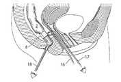
- FIG. 1shows how a surgeon uses a surgical tool 1 to access the rectum or colon 2 through an incision 3 in the wall 4 of the vagina 5 of the patient.
- FIG. 2 ashows a subsequent step of the method, where a viewing scope 6 has been inserted through the incision 3 in the wall 4 of the vagina 5 .
- the viewing scopeallows the surgeon to carry out surgical procedures in a minimally invasive manner.
- a surgical instrument 7which is described in detail below, is used for dissecting the area 9 around the rectum 2 to enable the implantation of the restriction device 8 .
- FIG. 2 ashows how the surgical instrument 7 is used for introducing the restriction device 8 in its open conformation into the vagina for subsequent insertion to the correct place in a manner described in more detail below.
- FIG. 2 bshows the next step of the method, where the surgical instrument has brought the restriction device 8 , which is still in its open conformation, though an incision 3 in the wall 4 of the vagina 5 , to the rectum 2 .
- FIG. 3shows an even later step in the surgical procedure.
- the restriction device 8is now in place engaging the rectum 2 and the surgical instrument 7 is being retracted.
- the restriction deviceis now in its closed conformation.
- Other devices that are to be connected to the restriction devicesuch a control device, a switch, a energy source and a sensor can be implanted and connected to the restriction device during the same procedure, if desired.
- FIG. 4shows en embodiment of the invention where a laparoscopical method is used for carrying out the implantation of the restriction device.
- Laparoscopic proceduresinvolve percutaneously accessing an internal surgical site with small-diameter access tubes (typically 5 to 12 mm diameter), usually referred to as laparoscopic trocars, which penetrate the skin and permit access to the surgical site.
- a viewing scopeis introduced through at least one laparoscopic trocar and the surgeon performs surgery using instruments inserted through other appropriately placed laparoscopic trocar(s) while viewing the operative site on for instance a video monitor connected to the viewing scope.
- the surgeonis thus able to perform a wide variety of surgical procedures requiring only a few 5 to 12 mm punctures at the surgical site. Consequently, patient trauma and recovery time are greatly reduced.
- Laparoscopic proceduresinvolve the insufflation of the surgical site with gas in order to create sufficient operating space to perform a desired procedure. Usually more than one trocar is used.
- trocarsare inserted in the vagina 5 and trough the wall of the vagina 4 of the patient in order to access the rectum 2 .
- One trocar 16is used for placing a restriction device 8 around the rectum 2 and one trocar 17 is used for inserting a viewing scope or a camera for observing the rectum 2 from the outside.
- FIG. 5 ashows a surgical instrument 7 according to the invention.
- the instrumentis used for being held by the surgeon, being inserted through an incision in the vagina so that it reaches a portion of the rectum or colon where the restriction device is going to be implanted, dissecting a portion of the rectum or colon so that the instrument, which can form a loop, can reach around the rectum or colon.
- the instrumentis then connected to the restriction device and the restriction device is then in its straight conformation.
- the instrumentis then retracted, pulling the restriction device in place behind the rectum or colon.
- the restriction deviceis then closed to form a loop around the rectum or colon.
- the instrument 7comprises a main part with a handle 21 on to which an elongated member 23 is mounted at an angle A between the extension of the main part of the instrument 21 and the elongated member 23 of from 0° to 160° to the main part of the instrument 21 .
- the elongated member 23is connected to the main part of the instrument by a joint 42 such that the angle A between the main part of the instrument and the elongated member is variable.
- the main part of the instrument 21is preferably elongated in order for the surgeon to reach the rectum and/or colon through an incision in the vagina.
- the flexible tip 24 of the elongated member 23is flexible and can change conformation from an essentially straight conformation to a loop conformation as seen in FIG. 5 b -5 c . In one embodiment this is achieved by a flexible gooseneck that is essentially smooth. In one embodiment, the flexible tip 24 can move in any direction.
- the loopdoes not necessarily have to form a closed circle but preferably a large enough portion of a circle so that the attachment structure 26 protrudes from the other side of the rectum or colon when the flexible tip 24 surrounds the rectum or colon.
- the loopforms 270 degrees of a circle, or more.
- the flexibility of the flexible tip 24can be achieved in different manners that are disclosed by prior art. The change in conformation can be carried out mechanically, i.e.
- the bending of the flexible tip 24is controlled by a means selected from the group consisting of a mechanical mean, an electric mean and a hydraulic mean.
- the control of the bending of the flexible tip 24is achieved by at least two parallel wires that run inside the flexible tip 24 , where one end of each wire is connected to the head 25 and one end of the wire is connected to the elongated member 23 , and tension can be applied to each of the wires independently.
- the instrumenthas one device 40 for manoeuvring the bending of the flexible tip 24 and one switch 41 for controlling the attachment structure 26 .
- the flexible tip 24is connected to the elongated member by a ball-and-socket joint. This makes it possibly to use the instrument from right to left or from left to right, depending on the preferences of the surgeon.
- the head 25 of the flexible tip 24has two functions. It comprises a soft tissue dissector 27 and an attachment structure 26 for the restriction device.
- the dissectoris adapted for dissecting soft tissue and passing through the tissue surrounding the rectum or colon.
- the flexible tip 24is flexible it is still rigid enough to be used to dissect the area around the rectum or colon.
- the tissue surrounding the rectum and colonconsists mostly of fibrotic tissue and fat tissue that is comparatively soft and can be dissected by using a blunt instrument.
- the loop conformation of the flexible tip 24 of the surgical instrument 7is adapted to reach around the rectum or colon and thus has an inner diameter that is larger than the outer diameter of the rectum or colon.
- the loophas an inner diameter of 6-12 cm.
- FIG. 5 dshows a different embodiment of the surgical instrument.
- the elongated member 23is equipped with an extra joint 43 that facilitates the bending of the elongated member 23 around the rectum 2 .
- the additional joint 43introduces a second angle (B) between the parts of elongated member 23 separated by joint 43 .
- the angle (B)can retain the same values as angle (A), but can be adjusted separately therefrom with the joint 43 .
- the additional jointincreases the flexibility when operating the surgical instrument.
- the additional joint 43facilitates the bending of the elongated member 23 around a body lumen (such as the rectum or the urethra.)
- the head 25 of the flexible tip 24comprises an attachment structure 26 for reversibly associating the instrument with an implantable restriction device.
- Various embodiments of the attachment structure 26are shown in FIGS. 5 c - f .
- the attachment structure 26is selected from a notch where a string can be attached ( 5 c ), a pincer ( 5 d ), a toothed pincer ( 5 e ) and a noose ( 5 f ).
- the attachment structure 26 of the instrument 7comprises a coupling that can be associated with a corresponding coupling on the restriction device 8 .
- the attachment structure 26 of the instrument 7comprises a fast coupling.
- the attachment structurecomprises a fast coupling.
- the attachment structurecomprises a pincer.
- the instrumentcomprises a viewing scope which the surgeon can use to observe the site of surgery.
- the dissectoris a soft tissue dissector.
- FIGS. 6 a - dshows one intended use of the surgical instrument 7 .
- the soft tissue dissector 27 of the end 25 of the flexible tip 24is used to push through the tissue 9 surrounding the rectum or colon 2 as shown in FIG. 6 a .
- the flexible tip 24When the flexible tip 24 has reached behind the rectum or colon 2 it is slightly bent so that it can dissect behind the rectum or colon 2 .
- the flexible tip 24is then slightly bent and moved inwards so that it can reach even further behind the colon or rectum 2 until the attachment structure 26 of the head 25 of the flexible tip 24 protrudes from the other side of the rectum or colon as shown in FIG. 6 b .
- the restriction device 8which is in its straight conformation, is brought into the site of surgery with the means of another instrument 29 .
- the attachment structure 26 of the surgical instrument 7is then attached to the restriction device 8 .
- the flexible tip 24is then retracted by performing the reverse movement, thereby pulling the restriction device 8 in place behind the colon or rectum 2 as shown in FIG. 6 c .
- the restriction device 8is now essentially in place and is detached from the attachment structure 26 of the surgical instrument 7 .
- the restriction device 8is then closed to form a loop around the rectum 2 as seen in FIG. 6 d.
- the introductionary hoseshould in this case be represented in ( 8 ) covering the restriction device as in FIG. 60 .
- the methodcomprises;
- said hosecomprising a holding part, adapted to allow an instrument to hold said hose at the first introductionary end to ease the introduction of the device, wherein the method step of introducing said restriction device by using said introductionary hose ( 8 ) in FIG. 6 c comprises;
- the device 8is attached to the instrument 7 before the flexible tip 24 is brought in behind the colon or rectum 2 .
- the device 8is brought in place as the flexible tip 24 bends around the colon or rectum 2 and the additional instrument 29 is not needed.
- the instrument 7comprises a viewing scope allowing implantation of the device to be carried out with a minimally invasive procedure.
- the surgical instrument 7is in one embodiment used for implanting devices that are associated with the restriction device, such as a control device for controlling the adjustment of the restriction device, and devices for powering the device and for storing energy. Also, in one embodiment, switches sensors and leads are implanted. In one embodiment, more than one restriction device is implanted.
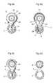
- FIG. 7shows a restriction device 8 according to the invention.
- the restriction deviceis flexible and can change conformation from being essentially straight to being a loop with an inner circumference of a size such that it engages the rectum or colon.
- the restriction device 8has a smooth surface 44 without protruding parts that makes it adapted to be dragged around behind the rectum or colon by the surgical instrument without snagging or getting stuck. In one embodiment it is pointed, rounded or streamlined making it suitable for being pulled in place without damaging the colon or rectum or surrounding tissues. Thus, at least one end 45 of the restriction device is pointed.
- the restriction device 8has locking mechanism 28 whereby it can be made to form a loop.
- the locking mechanismis of a self-lock type.
- At least one end 45 of the restriction device 8has an attachment structure adapted to be reversibly associated with the attachment structure 26 of the surgical instrument 7 . In one embodiment this is a fast coupling.
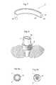
- FIG. 8shows the restriction device 8 in place as it is engaging the rectum 2 .
- the restriction device 8forms a loop around the rectum 2 .
- the inner diameter) of the loopis adjustable, thereby opening or closing the rectum as seen in FIG. 9 a and FIG. 9 b where FIG. 9 a shows the open state and 9 b shows the closed state where the lumen 30 of the colon or rectum 2 is essentially extinct.
- the change in diameteris carried out by mean selected from a hydraulic mean and a mechanical mean well known to the person skilled in the art. Examples of prior art include but are not limited to U.S. Pat. No. 7,367,938 and EP 1 255 511. In the embodiment shown in FIG. 9 the change of diameter is achieved by a hydraulic mean.
- Coloscopyis a technology that involves inserting a probe with a camera in the colon of the patient. This enables the operator to visually inspect the rectum or the colon.
- the surgical procedureis combined with coloscopy. This enables the surgeon to observe the lumen of the colon or rectum while surgery is being performed. This is used to, for example, see how much the rectum contracts when the restriction device is engaged and allows for the verification of the correct positioning of the restriction device.
- FIG. 10shows how a coloscope 18 is inserted through the rectum 2 enabling the surgeon to observe the interior of the rectum 2 , while using trocars 16 , 17 for placing a restriction device 8 as to engage the colon 2 and for observing the colon 2 from the outside.
- coloscopyis used for placing a sensor in the patient.
- the sensormeasures an electrical parameter.
- the sensormeasures at least one parameter from the group consisting of pressure, volume, diameter, stretching, elongation, extension, movement, elasticity, muscle contraction, temperature, flow and nerve impulse.
- output from the sensoris used for calibrating the restriction device.
- the restriction deviceis placed as to engage the colon rather than the rectum.
- the restriction deviceis fixed in the body of the patient. In one embodiment this is done by fixating the restriction device in the adjacent tissue. In one embodiment the restriction device is fixed in the patient by creating a tunnel of tissue from the colon or rectum of the patient. After fixating, the incision(s) in the patient is closed. In one embodiment this is achieved by suturing in layers. If a minimally invasive procedure has been used, the incision may be so small that other means are used. Examples include, but are not limited to, stapling and taping.
- the rectum, the colon and the anal sphincterare equipped with muscle tissue that is able to contract and thus control the movement of faeces. Dysfunction of this capacity can be one cause of anal incontinence. However, the capacity of muscle tissue to contract may be partially or completely restored by stimulating the muscle tissue with electricity. In one embodiment the method comprises stimulating contraction of the muscles surrounding the rectum, colon and/or anal sphincter by using electricity. In one embodiment, the stimulation takes place in more than one location of the restriction device.
- FIG. 11shows the restriction device 8 implanted as to engage the rectum 2 . It is adjustable and connected to the control device 38 by a power- and control cord 30 .
- the control devicemay comprise a subcutaneous switch 31 , a receiver for wireless energy 32 , a battery 33 , a receiver 34 for energy and a remote control 35 . Wireless energy is transmitted by a transmitter 36 .
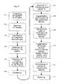
- FIG. 12is a flow chart showing one embodiment that includes several of the steps of the disclosed method where a laparoscopic method for surgery is used. In other embodiments, one or more steps may be omitted or performed in a different order.
- the patientis prepared for surgery in a manner that is known to a person skilled in the art. In one embodiment the method is performed on the patient in the supine position.
- a needleis introduced into the site of operation.
- the site of operationis insufflated with a gas so that the site of operation is expanded.
- Step 104is the insertion into the vagina of trocars. At least one trocar is used for viewing the operation site and at least one trocar is used for performing various surgical steps.
- the trocarsare then in step 105 inserted through the wall of the vagina.
- the trocarsare inserted through the posterior wall of the vagina.
- the tips of the trocarsare brought up to site of surgery which is the outside of the colon and/or rectum.
- Step 106is dissection of the colon and/or rectum.
- a colonoscopeis then, in step 107 , inserted through the anus.
- a sensor(sensor A in the figure) is introduced by using the colonoscope.
- the colonoscopeis used to observe the rectum and/or colon from the inside during step 108 , which is the implantation of the restriction device so that it engages the rectum and/or colon.
- the surgeoncan ensure that the restriction device engages the rectum and/or colon in a correct manner.
- the restriction deviceis fixated in the surrounding tissue of the patient in step 108 .
- Sensor Ais used in step 109 to calibrate the restriction device.
- Sensor Ais then removed from the patient.
- other partsare implanted in the patient, such as, but not limited to, an energy source, a control device and a switch. These may be included in the same subcutaneous implant.
- a control cord, that connects the restriction device to the control device, and sensor B,are also implanted, in one embodiment.
- Step 111is the withdrawal of the trocars, the colonoscope and sensor A.
- step 112the incisions are closed by suturing or other means, such as taping, clamping or stapling.
- step 109is omitted.
- step 107is omitted.
- step 107is carried out before step 106 .
- step 110is carried out before step 109 .
- FIG. 13shows one embodiment of how the method is used postoperatively, where the implanted parts are used to control defecation in an anal incontinent patient.
- step 201energy is transferred to the energy source.
- step 202the energy balance is used to optimize the transfer of energy.
- step 203the patient opens the restriction device to allow defecation.
- step 204the restriction device is closed after the patient has finished defecation. Simultaneously, electricity is used to stimulate contraction of muscles of the rectum or colon.
- the implanted sensor Bis used to calibrate the restriction device.
- step 205is omitted. In one embodiment, step 205 is carried out before step 203 .
- FIG. 14illustrates a method for treating a disease comprising the implantation of a system 1000 comprising a restriction device 8 of the present invention, in the patient.
- An implanted energy-transforming device 1002is adapted to supply energy consuming components of the restriction device 8 with energy via a power supply line 1003 .
- An external energy-transmission device 1004 for non-invasively energizing the restriction device 8transmits energy by at least one wireless energy signal.
- the implanted energy-transforming device 1002transforms energy from the wireless energy signal into electric energy which is supplied via the power supply line 1003 .
- the implanted energy-transforming device 1002may also comprise other components, such as: a coil for reception and/or transmission of signals and energy, an antenna for reception and/or transmission of signals, a microcontroller, a charge control unit, optionally comprising an energy storage, such as a capacitor, one or more sensors, such as temperature sensor, pressure sensor, position sensor, motion sensor etc., a transceiver, a motor, optionally including a motor controller, a pump, and other parts for controlling the operation of a medical implant.
- a coilfor reception and/or transmission of signals and energy
- an antennafor reception and/or transmission of signals
- a microcontrollere.g., a microcontroller
- a charge control unitoptionally comprising an energy storage, such as a capacitor
- sensorssuch as temperature sensor, pressure sensor, position sensor, motion sensor etc.
- a transceivere.g., a motor controller, a pump, and other parts for controlling the operation of a medical implant.
- the wireless energy signalmay include a wave signal selected from the following: a sound wave signal, an ultrasound wave signal, an electromagnetic wave signal, an infrared light signal, a visible light signal, an ultra violet light signal, a laser light signal, a micro wave signal, a radio wave signal, an x-ray radiation signal and a gamma radiation signal.
- the wireless energy signalmay include an electric or magnetic field, or a combined electric and magnetic field.
- the wireless energy-transmission device 1004may transmit a carrier signal for carrying the wireless energy signal.
- a carrier signalmay include digital, analogue or a combination of digital and analogue signals.
- the wireless energy signalincludes an analogue or a digital signal, or a combination of an analogue and digital signal.
- the energy-transforming device 1002is provided for transforming wireless energy of a first form transmitted by the energy-transmission device 1004 into energy of a second form, which typically is different from the energy of the first form.
- the implanted restriction device Bis operable in response to the energy of the second form.
- the energy-transforming device 1002may directly power the restriction device 8 with the second form energy, as the energy-transforming device 1002 transforms the first form energy transmitted by the energy-transmission device 1004 into the second form energy.
- the systemmay further include an implantable accumulator, wherein the second form energy is used at least partly to charge the accumulator.
- the wireless energy transmitted by the energy-transmission device 1004may be used to directly power the restriction device 8 and any components connected thereto, as the wireless energy is being transmitted by the energy-transmission device 1004 .
- the systemcomprises an operation device for operating the restriction device 8
- the wireless energy transmitted by the energy-transmission device 1004may be used to directly power the operation device to create kinetic energy for the operation of the restriction device.
- the wireless energy of the first formmay comprise sound waves and the energy-transforming device 1002 may include a piezo-electric element for transforming the sound waves into electric energy.
- the energy of the second formmay comprise electric energy in the form of a direct current or pulsating direct current, or a combination of a direct current and pulsating direct current, or an alternating current or a combination of a direct and alternating current.
- the restriction device 8comprises electric components that are energized with electrical energy.
- Other implantable electric components of the systemmay be at least one voltage level guard or at least one constant current guard connected with the electric components of the restriction device 8 .
- the energy of the first form and the energy of the second formmay comprise magnetic energy, kinetic energy, sound energy, chemical energy, radiant energy, electromagnetic energy, photo energy, nuclear energy or thermal energy.
- the energy of the first form and the energy of the second formare non-magnetic, non-kinetic, non-chemical, non-sonic, non-nuclear or non-thermal.
- the energy-transmission devicemay be controlled from outside the patient's body to release electromagnetic wireless energy, and the released electromagnetic wireless energy is used for operating the restriction device 8 .
- the energy-transmission deviceis controlled from outside the patient's body to release non-magnetic wireless energy, and the released non-magnetic wireless energy is used for operating the restriction device 8 .
- the external energy-transmission device 1004also includes a wireless remote control having an external signal transmitter for transmitting a wireless control signal for non-invasively controlling the restriction device 8 .
- the control signalis received by an implanted signal receiver which may be incorporated in the implanted energy-transforming device 1002 or be separate there from.
- the wireless control signalmay include a frequency, amplitude, or phase modulated signal or a combination thereof.
- the wireless control signalincludes an analogue or a digital signal, or a combination of an analogue and digital signal.
- the wireless control signalcomprises an electric or magnetic field, or a combined electric and magnetic field.
- the wireless remote controlmay transmit a carrier signal for carrying the wireless control signal.
- a carrier signalmay include digital, analogue or a combination of digital and analogue signals.
- the control signalincludes an analogue or a digital signal, or a combination of an analogue and digital signal
- the wireless remote controlpreferably transmits an electromagnetic carrier wave signal for carrying the digital or analogue control signals.
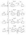
- FIG. 15illustrates the system 1000 of FIG. 14 in the form of a more generalized block diagram showing the restriction device 8 , the energy-transforming device 1002 powering the restriction device 8 via power supply line 1003 , and the external energy-transmission device 1004 .
- the patient's skin 1005generally shown by a vertical line, separates the interior of the patient to the right of the line from the exterior to the left of the line.
- FIG. 16shows an embodiment of the invention identical to that of FIG. 15 , except that a reversing device in the form of an electric switch 1006 operable for example by polarized energy also is implanted in the patient for reversing the restriction device 8 .
- the wireless remote control of the external energy-transmission device 1004transmits a wireless signal that carries polarized energy and the implanted energy-transforming device 1002 transforms the wireless polarized energy into a polarized current for operating the electric switch 1006 .
- the electric switch 1006reverses the function performed by the restriction device 8 .
- FIG. 17shows an embodiment of the invention identical to that of FIG. 15 , except that an operation device 1007 implanted in the patient for operating the restriction device 8 is provided between the implanted energy-transforming device 1002 and the restriction device 8 .
- This operation devicecan be in the form of a motor 1007 , such as an electric servomotor.
- the motor 1007is powered with energy from the implanted energy-transforming device 1002 , as the remote control of the external energy-transmission device 1004 transmits a wireless signal to the receiver of the implanted energy-transforming device 1002 .
- FIG. 18shows an embodiment of the invention identical to that of FIG. 15 , except that it also comprises an operation device in the form of an assembly 1008 including a motor/pump unit 1009 and a fluid reservoir 1010 is implanted in the patient.
- the restriction device 8is hydraulically operated, i.e. hydraulic fluid is pumped by the motor/pump unit 1009 from the fluid reservoir 1010 through a conduit 1011 to the restriction device 8 to operate the restriction device 8 , and hydraulic fluid is pumped by the motor/pump unit 1009 back from the restriction device 8 to the fluid reservoir 1010 to return the restriction device 8 to a starting position.
- the implanted energy-transforming device 1002transforms wireless energy into a current, for example a polarized current, for powering the motor/pump unit 1009 via an electric power supply line 1012 .
- the operation devicecomprises a pneumatic operation device.
- the hydraulic fluidcan be pressurized air to be used for regulation and the fluid reservoir is replaced by an air chamber.
- the energy-transforming device 1002may include a rechargeable accumulator like a battery or a capacitor to be charged by the wireless energy and supplies energy for any energy consuming part of the system.
- the wireless remote control described abovemay be replaced by manual control of any implanted part to make contact with by the patient's hand most likely indirect, for example a press button placed under the skin.
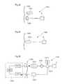
- FIG. 19shows an embodiment of the invention comprising the external energy-transmission device 1004 with its wireless remote control, the restriction device 8 , in this case hydraulically operated, and the implanted energy-transforming device 1002 , and further comprising a hydraulic fluid reservoir 1013 , a motor/pump unit 1009 and an reversing device in the form of a hydraulic valve shifting device 1014 , all implanted in the patient.
- the remote controlmay be a device separated from the external energy-transmission device or included in the same.
- the motor of the motor/pump unit 1009is an electric motor.
- the implanted energy-transforming device 1002powers the motor/pump unit 1009 with energy from the energy carried by the control signal, whereby the motor/pump unit 1009 distributes hydraulic fluid between the hydraulic fluid reservoir 1013 and the restriction device 8 .
- the remote control of the external energy-transmission device 1004controls the hydraulic valve shifting device 1014 to shift the hydraulic fluid flow direction between one direction in which the fluid is pumped by the motor/pump unit 1009 from the hydraulic fluid reservoir 1013 to the restriction device 8 to operate the restriction device 9 , and another opposite direction in which the fluid is pumped by the motor/pump unit 1009 back from the restriction device 8 to the hydraulic fluid reservoir 1013 to return the restriction device 8 to a starting position.
- FIG. 20shows an embodiment of the invention comprising the external energy-transmission device 1004 with its wireless remote control, the restriction device 8 , the implanted energy-transforming device 1002 , an implanted internal control unit 1015 controlled by the wireless remote control of the external energy-transmission device 1004 , an implanted accumulator 1016 and an implanted capacitor 1017 .
- the internal control unit 1015arranges storage of electric energy received from the implanted energy-transforming device 1002 in the accumulator 1016 , which supplies energy to the restriction device 8 .
- the internal control unit 1015In response to a control signal from the wireless remote control of the external energy-transmission device 1004 , the internal control unit 1015 either releases electric energy from the accumulator 1016 and transfers the released energy via power lines 1018 and 1019 , or directly transfers electric energy from the implanted energy-transforming device 1002 via a power line 1020 , the capacitor 1017 , which stabilizes the electric current, a power line 1021 and the power line 1019 , for the operation of the restriction device 8 .
- the internal control unitis preferably programmable from outside the patient's body.
- the internal control unitis programmed to regulate the restriction device 8 according to a pre-programmed time-schedule or to input from any sensor sensing any possible physical parameter of the patient or any functional parameter of the system.
- the capacitor 1017 in the embodiment of FIG. 20, 10may be omitted.
- the accumulator 1016 in this embodimentmay be omitted.
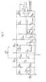
- FIG. 21shows an embodiment of the invention identical to that of FIG. 15 , except that a battery 1022 for supplying energy for the operation of the restriction device 8 and an electric switch 1023 for switching the operation of the restriction device 8 also are implanted in the patient.
- the electric switch 1023may be controlled by the remote control and may also be operated by the energy supplied by the implanted energy-transforming device 1002 to switch from an off mode, in which the battery 1022 is not in use, to an on mode, in which the battery 1022 supplies energy for the operation of the restriction device 8 .
- FIG. 22shows an embodiment of the invention identical to that of FIG. 21 , except that an internal control unit 1015 controllable by the wireless remote control of the external energy-transmission device 1004 also is implanted in the patient.
- the electric switch 1023is operated by the energy supplied by the implanted energy-transforming device 1002 to switch from an off mode, in which the wireless remote control is prevented from controlling the internal control unit 1015 and the battery is not in use, to a standby mode, in which the remote control is permitted to control the internal control unit 1015 to release electric energy from the battery 1022 for the operation of the restriction device 8 .
- FIG. 23shows an embodiment of the invention identical to that of FIG. 22 , except that an accumulator 1016 is substituted for the battery 1022 and the implanted components are interconnected differently.
- the accumulator 1016stores energy from the implanted energy-transforming device 1002 .
- the internal control unit 1015controls the electric switch 1023 to switch from an off mode, in which the accumulator 1016 is not in use, to an on mode, in which the accumulator 1016 supplies energy for the operation of the restriction device 8 .
- the accumulatormay be combined with or replaced by a capacitor.
- FIG. 24shows an embodiment of the invention identical to that of FIG. 23 , except that a battery 1022 also is implanted in the patient and the implanted components are interconnected differently.
- the internal control unit 1015controls the accumulator 1016 to deliver energy for operating the electric switch 1023 to switch from an off mode, in which the battery 1022 is not in use, to an on mode, in which the battery 1022 supplies electric energy for the operation of the restriction device 8 .
- the electric switch 1023may be operated by energy supplied by the accumulator 1016 to switch from an off mode, in which the wireless remote control is prevented from controlling the battery 1022 to supply electric energy and is not in use, to a standby mode, in which the wireless remote control is permitted to control the battery 1022 to supply electric energy for the operation of the restriction device 8 .
- switch 1023 and all other switches in this applicationshould be interpreted in its broadest embodiment.
- the switchis controlled from outside the body, or alternatively by an implanted internal control unit.
- FIG. 25shows an embodiment of the invention identical to that of FIG. 21 , except that a motor 1007 , a mechanical reversing device in the form of a gear box 1024 , and an internal control unit 1015 for controlling the gear box 1024 also are implanted in the patient.
- the internal control unit 1015controls the gear box 1024 to reverse the function performed by the restriction device 8 (mechanically operated). Even simpler is to switch the direction of the motor electronically.
- the gear box interpreted in its broadest embodimentmay stand for a servo arrangement saving force for the operation device in favour of longer stroke to act.
- FIG. 26shows an embodiment of the invention identical to that of FIG. 25 except that the implanted components are interconnected differently.
- the internal control unit 1015is powered by the battery 1022 when the accumulator 1016 , suitably a capacitor, activates the electric switch 1023 to switch to an on mode.
- the electric switch 1023is in its on mode the internal control unit 1015 is permitted to control the battery 1022 to supply, or not supply, energy for the operation of the restriction device 8 .
- FIG. 27schematically shows conceivable combinations of implanted components of the restriction device 8 for achieving various communication options.
- the restriction device 8there are the restriction device 8 , the internal control unit 1015 , motor or pump unit 1009 , and the external energy-transmission device 1004 including the external wireless remote control.
- the wireless remote controltransmits a control signal which is received by the internal control unit 1015 , which in turn controls the various implanted components of the restriction device 8 .
- a feedback devicepreferably comprising a sensor or measuring device 1025 , may be implanted in the patient for sensing a physical parameter of the patient.
- the physical parametermay be at least one selected from the group consisting of pressure, volume, diameter, stretching, elongation, extension, movement, bending, elasticity, muscle contraction, nerve impulse, body temperature, blood pressure, blood flow, heartbeats and breathing.
- the sensormay sense any of the above physical parameters.
- the sensormay be a pressure or motility sensor.
- the sensor 1025may be arranged to sense a functional parameter.
- the functional parametermay be correlated to the transfer of energy for charging an implanted energy source and may further include at least one selected from the group of parameters consisting of; electricity, any electrical parameter, pressure, volume, diameter, stretch, elongation, extension, movement, bending, elasticity, temperature and flow.
- the feedbackmay be sent to the internal control unit or out to an external control unit preferably via the internal control unit.
- Feedbackmay be sent out from the body via the energy transfer system or a separate communication system with receiver and transmitters.
- the internal control unit 1015may control the restriction device 8 in response to signals from the sensor 1025 .
- a transceivermay be combined with the sensor 1025 for sending information on the sensed physical parameter to the external wireless remote control.
- the wireless remote controlmay comprise a signal transmitter or transceiver and the internal control unit 1015 may comprise a signal receiver or transceiver.
- the wireless remote controlmay comprise a signal receiver or transceiver and the internal control unit 1015 may comprise a signal transmitter or transceiver.
- the above transceivers, transmitters and receiversmay be used for sending information or data related to the restriction device 8 from inside the patient's body to the outside thereof.
- FIG. 28shows an alternative embodiment wherein the restriction device 8 is regulated from outside the patient's body.
- the system 1000comprises a battery 1022 connected to the restriction device 8 via a subcutaneous electric switch 1026 .
- the regulation of the restriction device 8is performed non-invasively by manually pressing the subcutaneous switch, whereby the operation of the restriction device 8 is switched on and off.
- additional componentssuch as an internal control unit or any other part disclosed in the present application can be added to the system.
- Two subcutaneous switchesmay also be used. In the preferred embodiment one implanted switch sends information to the internal control unit to perform a certain predetermined performance and when the patient press the switch again the performance is reversed.
- FIG. 29shows an alternative embodiment, wherein the system 1000 comprises a hydraulic fluid reservoir 1013 hydraulically connected to the restriction device 8 .
- Non-invasive regulationis performed by manually pressing the hydraulic reservoir connected to the restriction device 8 .
- the hydraulic fluid reservoir 1013is adapted to work with an injection port for the injection of hydraulic fluid, preferably for calibration of hydraulic fluid.
- the systemmay include an external data communicator and an implantable internal data communicator communicating with the external data communicator.
- the internal communicatorfeeds data related to the restriction device 8 or the patient to the external data communicator and/or the external data communicator feeds data to the internal data communicator.
- FIG. 30schematically illustrates an arrangement of the system that is capable of sending information from inside the patient's body to the outside thereof to give feedback information related to at least one functional parameter of the restriction device 8 or system, or related to a physical parameter of the patient, in order to supply an accurate amount of energy to an implanted internal energy receiver 1002 connected to implanted energy consuming components of the restriction device 8 .
- an energy receiver 1002may include an energy source and/or an energy-transforming device. Briefly described, wireless energy is transmitted from an external energy source 1004 a located outside the patient and is received by the internal energy receiver 1002 located inside the patient. The internal energy receiver is adapted to directly or indirectly supply received energy to the energy consuming components of the restriction device 8 via a switch 1026 .
- An energy balanceis determined between the energy received by the internal energy receiver 1002 and the energy used for the restriction device 8 , and the transmission of wireless energy is then controlled based on the determined energy balance.
- the energy balancethus provides an accurate indication of the correct amount of energy needed, which is sufficient to operate the restriction device 8 properly, but without causing undue temperature rise.
- the patient's skinis indicated by a vertical line 1005 .
- the energy receivercomprises an energy-transforming device 1002 located inside the patient, preferably just beneath, the patient's skin 1005 .
- the implanted energy-transforming device 1002may be placed in the abdomen, thorax, muscle fascia (e.g. in the abdominal wall), subcutaneously, or at any other suitable location.
- the implanted energy-transforming device 1002is adapted to receive wireless energy E transmitted from the external energy-source 1004 a provided in an external energy-transmission device 1004 located outside the patient's skin 1005 in the vicinity of the implanted energy-transforming device 1002 .
- the wireless energy Emay generally be transferred by means of any suitable Transcutaneous Energy Transfer (TET) device, such as a device including a primary coil arranged in the external energy source 1004 a and an adjacent secondary coil arranged in the implanted energy-transforming device 1002 .
- TETTranscutaneous Energy Transfer
- a device including a primary coil arranged in the external energy source 1004 a and an adjacent secondary coil arranged in the implanted energy-transforming device 1002When an electric current is fed through the primary coil, energy in the form of a voltage is induced in the secondary coil which can be used to power the implanted energy consuming components of the restriction device 8 , e.g. after storing the incoming energy in an implanted energy source, such as a rechargeable battery or a capacitor.
- an implanted energy sourcesuch as a rechargeable battery or a capacitor.
- the present inventionis generally not limited to any particular energy transfer technique, TET devices or energy sources, and any kind of wireless energy may be used.
- the amount of energy received by the implanted energy receivermay be compared with the energy used by the implanted components of the restriction device 8 .
- the term “energy used”is then understood to include also energy stored by implanted components of the restriction device 8 .
- a control deviceincludes an external control unit 1004 b that controls the external energy source 1004 a based on the determined energy balance to regulate the amount of transferred energy. In order to transfer the correct amount of energy, the energy balance and the required amount of energy is determined by means of a determination device including an implanted internal control unit 1015 connected between the switch 1026 and the restriction device 8 .
- the internal control unit 1015may thus be arranged to receive various measurements obtained by suitable sensors or the like, not shown, measuring certain characteristics of the restriction device 8 , somehow reflecting the required amount of energy needed for proper operation of the restriction device 8 .
- the current condition of the patientmay also be detected by means of suitable measuring devices or sensors, in order to provide parameters reflecting the patient's condition.
- characteristics and/or parametersmay be related to the current state of the restriction device 8 , such as power consumption, operational mode and temperature, as well as the patient's condition reflected by parameters such as; body temperature, blood pressure, heartbeats and breathing.
- Other kinds of physical parameters of the patient and functional parameters of the deviceare described elsewhere.
- an energy source in the form of an accumulator 1016may optionally be connected to the implanted energy-transforming device 1002 via the control unit 1015 for accumulating received energy for later use by the restriction device 8 .
- characteristics of such an accumulatoralso reflecting the required amount of energy, may be measured as well.
- the accumulatormay be replaced by a rechargeable battery, and the measured characteristics may be related to the current state of the battery, any electrical parameter such as energy consumption voltage, temperature, etc. In order to provide sufficient voltage and current to the restriction device 8 , and also to avoid excessive heating, it is clearly understood that the battery should be charged optimally by receiving a correct amount of energy from the implanted energy-transforming device 1002 , i.e. not too little or too much.
- the accumulatormay also be a capacitor with corresponding characteristics.
- battery characteristicsmay be measured on a regular basis to determine the current state of the battery, which then may be stored as state information in a suitable storage means in the internal control unit 1015 .
- state informationin a suitable storage means in the internal control unit 1015 .
- the stored battery state informationcan be updated accordingly.
- the state of the batterycan be “calibrated” by transferring a correct amount of energy, so as to maintain the battery in an optimal condition.
- the internal control unit 1015 of the determination deviceis adapted to determine the energy balance and/or the currently required amount of energy, (either energy per time unit or accumulated energy) based on measurements made by the above-mentioned sensors or measuring devices of the restriction device 8 , or the patient, or an implanted energy source if used, or any combination thereof.
- the internal control unit 1015is further connected to an internal signal transmitter 1027 , arranged to transmit a control signal reflecting the determined required amount of energy, to an external signal receiver 1004 c connected to the external control unit 1004 b .
- the amount of energy transmitted from the external energy source 1004 amay then be regulated in response to the received control signal.
- the determination devicemay include the external control unit 1004 b .
- sensor measurementscan be transmitted directly to the external control unit 1004 b wherein the energy balance and/or the currently required amount of energy can be determined by the external control unit 1004 b , thus integrating the above-described function of the internal control unit 1015 in the external control unit 1004 b .
- the internal control unit 1015can be omitted and the sensor measurements are supplied directly to the internal signal transmitter 1027 which sends the measurements over to the external signal receiver 1004 c and the external control unit 1004 b .
- the energy balance and the currently required amount of energycan then be determined by the external control unit 1004 b based on those sensor measurements.
- the present solution according to the arrangement of FIG. 30employs the feedback of information indicating the required energy, which is more efficient than previous solutions because it is based on the actual use of energy that is compared to the received energy, e.g. with respect to the amount of energy, the energy difference, or the energy receiving rate as compared to the energy rate used by implanted energy consuming components of the restriction device 8 .
- the restriction device 8may use the received energy either for consuming or for storing the energy in an implanted energy source or the like.
- the different parameters discussed abovewould thus be used if relevant and needed and then as a tool for determining the actual energy balance. However, such parameters may also be needed per se for any actions taken internally to specifically operate the restriction device 8 .
- the internal signal transmitter 1027 and the external signal receiver 1004 cmay be implemented as separate units using suitable signal transfer means, such as radio, IR (Infrared) or ultrasonic signals.
- suitable signal transfer meanssuch as radio, IR (Infrared) or ultrasonic signals.
- the internal signal transmitter 1027 and the external signal receiver 1004 cmay be integrated in the implanted energy-transforming device 1002 and the external energy source 1004 a , respectively, so as to convey control signals in a reverse direction relative to the energy transfer, basically using the same transmission technique.
- the control signalsmay be modulated with respect to frequency, phase or amplitude.
- the feedback informationmay be transferred either by a separate communication system including receivers and transmitters or may be integrated in the energy system.
- an integrated information feedback and energy systemcomprises an implantable internal energy receiver for receiving wireless energy, the energy receiver having an internal first coil and a first electronic circuit connected to the first coil, and an external energy transmitter for transmitting wireless energy, the energy transmitter having an external second coil and a second electronic circuit connected to the second coil.
- the external second coil of the energy transmittertransmits wireless energy which is received by the first coil of the energy receiver.
- This systemfurther comprises a power switch for switching the connection of the internal first coil to the first electronic circuit on and off, such that feedback information related to the charging of the first coil is received by the external energy transmitter in the form of an impedance variation in the load of the external second coil, when the power switch switches the connection of the internal first coil to the first electronic circuit on and off.
- the switch 1026is either separate and controlled by the internal control unit 1015 , or integrated in the internal control unit 1015 . It should be understood that the switch 1026 should be interpreted in its broadest embodiment. This means a transistor, MCU, MCPU, ASIC FPGA or a DA converter or any other electronic component or circuit that may switch the power on and off.
- the energy supply arrangement illustrated in FIG. 30may operate basically in the following manner.
- the energy balanceis first determined by the internal control unit 1015 of the determination device.
- a control signal reflecting the required amount of energyis also created by the internal control unit 1015 , and the control signal is transmitted from the internal signal transmitter 1027 to the external signal receiver 1004 c .
- the energy balancecan be determined by the external control unit 1004 b instead depending on the implementation, as mentioned above.
- the control signalmay carry measurement results from various sensors.
- the amount of energy emitted from the external energy source 1004 acan then be regulated by the external control unit 1004 b , based on the determined energy balance, e.g. in response to the received control signal. This process may be repeated intermittently at certain intervals during ongoing energy transfer, or may be executed on a more or less continuous basis during the energy transfer.
- the amount of transferred energycan generally be regulated by adjusting various transmission parameters in the external energy source 1004 a , such as voltage, current, amplitude, wave frequency and pulse characteristics.
- This systemmay also be used to obtain information about the coupling factors between the coils in a TET system even to calibrate the system both to find an optimal place for the external coil in relation to the internal coil and to optimize energy transfer. Simply comparing in this case the amount of energy transferred with the amount of energy received. For example if the external coil is moved the coupling factor may vary and correctly displayed movements could cause the external coil to find the optimal place for energy transfer.
- the external coilis adapted to calibrate the amount of transferred energy to achieve the feedback information in the determination device, before the coupling factor is maximized.
- the energy system of the present inventioncomprises an implantable internal energy receiver for receiving wireless energy, the energy receiver having an internal first coil and a first electronic circuit connected to the first coil, and an external energy transmitter for transmitting wireless energy, the energy transmitter having an external second coil and a second electronic circuit connected to the second coil.
- the external second coil of the energy transmittertransmits wireless energy which is received by the first coil of the energy receiver.
- This systemfurther comprises a feedback device for communicating out the amount of energy received in the first coil as a feedback information
- the second electronic circuitincludes a determination device for receiving the feedback information and for comparing the amount of transferred energy by the second coil with the feedback information related to the amount of energy received in the first coil to obtain the coupling factor between the first and second coils.
- the energy transmittermay regulate the transmitted energy in response to the obtained coupling factor.
- FIG. 31Although wireless transfer of energy for operating the restriction device 8 has been described above to enable non-invasive operation, it will be appreciated that the restriction device 8 can be operated with wire bound energy as well.
- an external switch 1026is interconnected between the external energy source 1004 a and an operation device, such as an electric motor 1007 operating the restriction device 8 .
- An external control unit 1004 bcontrols the operation of the external switch 1026 to effect proper operation of the restriction device 8 .
- FIG. 32illustrates different embodiments for how received energy can be supplied to and used by the restriction device 8 .
- an internal energy receiver 1002receives wireless energy E from an external energy source 1004 a which is controlled by a transmission control unit 1004 b .
- the internal energy receiver 1002may comprise a constant voltage circuit, indicated as a dashed box “constant V” in the figure, for supplying energy at constant voltage to the restriction device 8 .
- the internal energy receiver 1002may further comprise a constant current circuit, indicated as a dashed box “constant C” in the figure, for supplying energy at constant current to the restriction device 8 .
- the restriction device 8comprises an energy consuming part 8 a , which may be a motor, pump, restriction device, or any other medical appliance that requires energy for its electrical operation.
- the restriction device 8may further comprise an energy storage device 8 b for storing energy supplied from the internal energy receiver 1002 .
- the supplied energymay be directly consumed by the energy consuming part 8 a , or stored by the energy storage device 8 b , or the supplied energy may be partly consumed and partly stored.
- the restriction device 8may further comprise an energy stabilizing unit 8 c for stabilizing the energy supplied from the internal energy receiver 1002 .
- the energymay be supplied in a fluctuating manner such that it may be necessary to stabilize the energy before consumed or stored.
- the energy supplied from the internal energy receiver 1002may further be accumulated and/or stabilized by a separate energy stabilizing unit 1028 located outside the restriction device 8 , before being consumed and/or stored by the restriction device 8 .
- the energy stabilizing unit 1028may be integrated in the internal energy receiver 1002 .
- the energy stabilizing unit 1028may comprise a constant voltage circuit and/or a constant current circuit.
- FIG. 30 and FIG. 32illustrate some possible but non-limiting implementation options regarding how the various shown functional components and elements can be arranged and connected to each other.
- FIG. 30 and FIG. 32illustrate some possible but non-limiting implementation options regarding how the various shown functional components and elements can be arranged and connected to each other.
- the skilled personwill readily appreciate that many variations and modifications can be made within the scope of the present invention.
- FIG. 33schematically shows an energy balance measuring circuit of one of the proposed designs of the system for controlling transmission of wireless energy, or energy balance control system.
- the circuithas an output signal centred on 2.5V and proportionally related to the energy imbalance. The derivative of this signal shows if the value goes up and down and how fast such a change takes place. If the amount of received energy is lower than the energy used by implanted components of the restriction device 8 , more energy is transferred and thus charged into the energy source.
- the output signal from the circuitis typically feed to an A/D converter and converted into a digital format. The digital information can then be sent to the external energy-transmission device allowing it to adjust the level of the transmitted energy.
- Another possibilityis to have a completely analogue system that uses comparators comparing the energy balance level with certain maximum and minimum thresholds sending information to external energy-transmission device if the balance drifts out of the max/min window.
- the schematic FIG. 33shows a circuit implementation for a system that transfers energy to the implanted energy components of the restriction device 8 of the present invention from outside of the patient's body using inductive energy transfer.
- An inductive energy transfer systemtypically uses an external transmitting coil and an internal receiving coil.
- the receiving coil, L 1is included in the schematic FIG. 33 ; the transmitting parts of the system are excluded.
- Energy to power the circuitis received by the energy receiving coil L 1 .
- Energy to implanted componentsis transmitted in this particular case at a frequency of 25 kHz.
- the energy balance output signalis present at test point Y 1 .
- the electric switch 1006 of FIG. 16could be incorporated in any of the embodiments of FIGS. 19-25
- the hydraulic valve shifting device 1014 of FIG. 19could be incorporated in the embodiment of FIG. 18
- the gear box 1024could be incorporated in the embodiment of FIG. 17 .
- the switchsimply could mean any electronic circuit or component.
- FIGS. 30, 32 and 33identify a method and a system for controlling transmission of wireless energy to implanted energy external energy transmitter can of course be implemented in numerous different ways.
- the schematic FIG. 33 and the above described method of evaluating and transmitting the informationshould only be regarded as examples of how to implement the control system.
- Energy to power the circuitis received by the energy receiving coil L 1 .
- Energy to implanted componentsis transmitted in this particular case at a frequency of 25 kHz.
- the energy balance output signalis present at test point Y 1 .
- the electric switch 1006 of FIG. 16could be incorporated in any of the embodiments of FIGS. 19-25
- the hydraulic valve shifting device 1014 of FIG. 19could be incorporated in the embodiment of FIG. 18
- the gear box 1024could be incorporated in the embodiment of FIG. 17 .
- the switchsimply could mean any electronic circuit or component.
- FIGS. 30, 32 and 33identify a method and a system for controlling transmission of wireless energy to implanted energy consuming components of an electrically operable restriction device 8 .
- Such a method and systemwill be defined in general terms in the following.
- a methodfor controlling transmission of wireless energy supplied to implanted energy consuming components of a restriction device 8 as described above.
- the wireless energy Eis transmitted from an external energy source located outside the patient and is received by an internal energy receiver located inside the patient, the internal energy receiver being connected to the implanted energy consuming components of the restriction device 8 for directly or indirectly supplying received energy thereto.
- An energy balanceis determined between the energy received by the internal energy receiver and the energy used for the restriction device 8 .
- the transmission of wireless energy E from the external energy sourceis then controlled based on the determined energy balance.
- the wireless energymay be transmitted inductively from a primary coil in the external energy source to a secondary coil in the internal energy receiver.
- a change in the energy balancemay be detected to control the transmission of wireless energy based on the detected energy balance change.
- a differencemay also be detected between energy received by the internal energy receiver and energy used for the medical device, to control the transmission of wireless energy based on the detected energy difference.
- the amount of transmitted wireless energymay be decreased if the detected energy balance change implies that the energy balance is increasing, or vice versa.
- the decrease/increase of energy transmissionmay further correspond to a detected change rate.
- the amount of transmitted wireless energymay further be decreased if the detected energy difference implies that the received energy is greater than the used energy, or vice versa.
- the decrease/increase of energy transmissionmay then correspond to the magnitude of the detected energy difference.
- the energy used for the medical devicemay be consumed to operate the medical device, and/or stored in at least one energy storage device of the medical device.
- the energymay be transmitted for consumption and storage according to a transmission rate per time unit which is determined based on said parameters.
- the total amount of transmitted energymay also be determined based on said parameters.
- the integralmay be determined for a monitored voltage and/or current related to the energy balance.
- the derivativeWhen the derivative is determined over time of a measured electrical parameter related to the amount of consumed and/or stored energy, the derivative may be determined for a monitored voltage and/or current related to the energy balance.
- the transmission of wireless energy from the external energy sourcemay be controlled by applying to the external energy source electrical pulses from a first electric circuit to transmit the wireless energy, the electrical pulses having leading and trailing edges, varying the lengths of first time intervals between successive leading and trailing edges of the electrical pulses and/or the lengths of second time intervals between successive trailing and leading edges of the electrical pulses, and transmitting wireless energy, the transmitted energy generated from the electrical pulses having a varied power, the varying of the power depending on the lengths of the first and/or second time intervals.
- the frequency of the electrical pulsesmay be substantially constant when varying the first and/or second time intervals.
- the electrical pulsesmay remain unchanged, except for varying the first and/or second time intervals.
- the amplitude of the electrical pulsesmay be substantially constant when varying the first and/or second time intervals. Further, the electrical pulses may be varied by only varying the lengths of first time intervals between successive leading and trailing edges of the electrical pulses.
- a train of two or more electrical pulsesmay be supplied in a row, wherein when applying the train of pulses, the train having a first electrical pulse at the start of the pulse train and having a second electrical pulse at the end of the pulse train, two or more pulse trains may be supplied in a row, wherein the lengths of the second time intervals between successive trailing edge of the second electrical pulse in a first pulse train and leading edge of the first electrical pulse of a second pulse train are varied.
- the electrical pulsesWhen applying the electrical pulses, the electrical pulses may have a substantially constant current and a substantially constant voltage.
- the electrical pulsesmay also have a substantially constant current and a substantially constant voltage. Further, the electrical pulses may also have a substantially constant frequency.
- the electrical pulses within a pulse trainmay likewise have a substantially constant frequency.
- the circuit formed by the first electric circuit and the external energy sourcemay have a first characteristic time period or first time constant, and when effectively varying the transmitted energy, such frequency time period may be in the range of the first characteristic time period or time constant or shorter.
- a system comprising an restriction device 8 as described aboveis thus also provided for controlling transmission of wireless energy supplied to implanted energy consuming components of the restriction device 8 .
- the systemcomprises a control device for controlling the transmission of wireless energy from an energy-transmission device, and an implantable internal energy receiver for receiving the transmitted wireless energy, the internal energy receiver being connected to implantable energy consuming components of the restriction device 8 for directly or indirectly supplying received energy thereto.
- the systemfurther comprises a determination device adapted to determine an energy balance between the energy received by the internal energy receiver and the energy used for the implantable energy consuming components of the restriction device 8 , wherein the control device controls the transmission of wireless energy from the external energy-transmission device, based on the energy balance determined by the determination device.
- At least one batterymay be a part of or replace the energy-transforming device 1002 to supply energy to the restriction device 8 over a power supply line.
- the batteryis not rechargeable.
- the batteryis rechargeable.
- the battery supplymay of course be placed both remote to and incorporated in the device.
- systemmay comprise any of the following:
- FIGS. 34-37show in more detail block diagrams of four different ways of hydraulically or pneumatically powering the implanted restriction device 8 according to the invention.
- FIG. 34shows a system as described above with.
- the systemcomprises an implanted restriction device 8 and further a separate regulation reservoir 1013 , a one way pump 1009 and an alternate valve 1014 .
- FIG. 35shows the restriction device 8 and a fluid reservoir 1013 .
- the adjustment of the restriction device 8may be performed without any valve, just free passage of fluid any time by moving the reservoir wall.
- FIG. 36shows the restriction device 8 , a two way pump 1009 and the regulation reservoir 1013 .
- FIG. 37shows a block diagram of a reversed servo system with a first closed system controlling a second closed system.
- the servo systemcomprises a regulation reservoir 1013 and a servo reservoir 1050 .
- the servo reservoir 1050mechanically controls an implanted restriction device 8 via a mechanical interconnection 1054 .
- the restriction device 8has an expandable/contactable cavity. This cavity is preferably expanded or contracted by supplying hydraulic fluid from the larger adjustable reservoir 1052 in fluid connection with the restriction device 8 . Alternatively, the cavity contains compressible gas, which can be compressed and expanded under the control of the servo reservoir 1050 .
- the servo reservoir 1050can also be part of the restriction device 8 itself.
- the regulation reservoiris placed subcutaneous under the patient's skin and is operated by pushing the outer surface thereof by means of a finger.
- This systemis illustrated in FIGS. 38 a - c .
- a flexible subcutaneous regulation reservoir 1013is shown connected to a bulge shaped servo reservoir 1050 by means of a conduit 1011 .
- This bellow shaped servo reservoir 1050is comprised in a flexible restriction device 8 .
- the servo reservoir 1050contains a minimum of fluid and most fluid is found in the regulation reservoir 1013 . Due to the mechanical interconnection between the servo reservoir 1050 and the restriction device 8 , the outer shape of the restriction device 8 is contracted, i.e., it occupies less than its maximum volume. This maximum volume is shown with dashed lines in the figure.
- FIG. 38 bshows a state wherein a user, such as the patient in with the restriction device 8 is implanted, presses the regulation reservoir 1013 so that fluid contained therein is brought to flow through the conduit 1011 and into the servo reservoir 1050 , which, thanks to its bellow shape, expands longitudinally. This expansion in turn expands the restriction device 8 so that it occupies its maximum volume, thereby stretching the stomach wall (not shown), which it contacts.
- the regulation reservoir 1013is preferably provided with means 1013 a for keeping its shape after compression. This means, which is schematically shown in the figure, will thus keep the restriction device 8 in a stretched position also when the user releases the regulation reservoir. In this way, the regulation reservoir essentially operates as an on/off switch for the system.
- FIG. 39comprises with a first closed system controlling a second closed system.
- the first systemcomprises a regulation reservoir 1013 and a servo reservoir 1050 .
- the servo reservoir 1050mechanically controls a larger adjustable reservoir 1052 via a mechanical interconnection 1054 .
- An implanted restriction device 8 having an expandable/contactable cavityis in turn controlled by the larger adjustable reservoir 1052 by supply of hydraulic fluid from the larger adjustable reservoir 1052 in fluid connection with the restriction device 8 .
- the regulation reservoiris placed subcutaneous under the patient's skin and is operated by pushing the outer surface thereof by means of a finger.
- the regulation reservoir 1013is in fluid connection with a bellow shaped servo reservoir 1050 by means of a conduit 1011 .
- the servo reservoir 1050contains a minimum of fluid and most fluid is found in the regulation reservoir 1013 .
- the servo reservoir 1050is mechanically connected to a larger adjustable reservoir 1052 , in this example also having a bellow shape but with a larger diameter than the servo reservoir 1050 .
- the larger adjustable reservoir 1052is in fluid connection with the restriction device 8 . This means that when a user pushes the regulation reservoir 1013 , thereby displacing fluid from the regulation reservoir 1013 to the servo reservoir 1050 , the expansion of the servo reservoir 1050 will displace a larger volume of fluid from the larger adjustable reservoir 1052 to the restriction device 8 . In other words, in this reversed servo, a small volume in the regulation reservoir is compressed with a higher force and this creates a movement of a larger total area with less force per area unit.
- the regulation reservoir 1013is preferably provided with means 1013 a for keeping its shape after compression. This means, which is schematically shown in the figure, will thus keep the restriction device 8 in a stretched position also when the user releases the regulation reservoir. In this way, the regulation reservoir essentially operates as an on/off switch for the system.
Landscapes
- Health & Medical Sciences (AREA)
- Life Sciences & Earth Sciences (AREA)
- General Health & Medical Sciences (AREA)
- Urology & Nephrology (AREA)
- Surgery (AREA)
- Veterinary Medicine (AREA)
- Engineering & Computer Science (AREA)
- Biomedical Technology (AREA)
- Heart & Thoracic Surgery (AREA)
- Public Health (AREA)
- Animal Behavior & Ethology (AREA)
- Transplantation (AREA)
- Vascular Medicine (AREA)
- Oral & Maxillofacial Surgery (AREA)
- Nuclear Medicine, Radiotherapy & Molecular Imaging (AREA)
- Cardiology (AREA)
- Medical Informatics (AREA)
- Molecular Biology (AREA)
- Prostheses (AREA)
Abstract
Description
- inserting a tube or needle trough an opening in the vaginal wall of the patient into the body of the patient,
- using said tube or needle to insufflate a site in a surrounding of at least one organ selected from group consisting of: the colon, anal channel, the rectum, and the anal sphincter, of the body of the patient with a gas
- inserting at least two laparoscopic tracers into said site,
- inserting at least one camera trough at least one of said at least two laparoscopic trocars, and
- inserting at least one dissecting tool through at least one of said laparoscopic trocars,
- dissecting in the patient at least one organ selected from the group consisting of: the colon, anal channel, the small intestine connected to the anus, the rectum, and the anal sphincter,
- implanting at least one powered restriction device in a position that enables it to decrease the cross-sectional area of the colon or rectum or anal sphincter in order to at least decrease the movement of faces through said passageway.
- entering the abdominal sac from the vaginal opening,
- placing said device in the abdominal peritoneal cavity,
- fixating said device by the a tunnel created in the mesenterium of the intestine.
- entering the fibrotic tissue surrounding the anal channel below the abdominal sac from the vaginal opening,
- placing said device in a tunnel of said fibrotic tissue below the abdominal peritoneal cavity,
- fixating said device by said tunnel.
- placing an energy receiver for receiving wireless energy subcutaneously just above the symphysis bone
- placing an electrical wire between the energy receiver and the device using said vaginal opening as an intermediate passage by,
- tunnelating the wire subcutaneously from the energy receiver to the device.
- placing an energy receiver for receiving wireless energy subcutaneously just above the symphysis bone
- placing a pump and reservoir above the symphysis bone preferable in the abdominal cavity,
- tunnelating a hydraulic tube subcutaneously from the pump to the device using said vaginal opening as an intermediate passage.
- introducing a camera through said vaginal opening.
- when introducing a camera through said vaginal opening,
- using said camera to go around the intestine and
- attaching said device to said camera to thereby,
- passing said device around the intestine,
- using said camera.
- mounting the restriction device inside said introductionary hose,
- introducing said restriction device around the colon or anus or a small intestine connected to the anus, by using said introductionary hose (8),
- releasing said restriction device from said introductionary hose, and
- withdrawing said hose from the device.
- inserting said instrument (7) via vagina around the colon or anus or a small intestine connected to the anus,
- attaching said holding part of said introductionary hose to said instrument, and
- introducing said hose around the colon or anus or a small intestine connected to the anus.
“system” refers to the restriction device and components connected thereto includes the restriction device and any operating device, energy receiver, determination device, energy-transforming device, switches and other components connected (wireless or not) to the restriction device whether electrical, mechanical or hydraulic.
- mounting the restriction device inside said introductionary hose,
- introducing said restriction device around the colon or anus or a small intestine connected to the anus, by using said introductionary hose (8),
- releasing said restriction device from said introductionary hose, and
- withdrawing said hose from the device.
- inserting said instrument (7) via vagina around the colon or anus or a small intestine connected to the anus,
- attaching said holding part of said introductionary hose to said instrument, and
- introducing said hose around the colon or anus or a small intestine connected to the anus.
- A primary coil in the external energy source adapted to transmit the wireless energy inductively to a secondary coil in the internal energy receiver.
- The determination device is adapted to detect a change in the energy balance, and the control device controls the transmission of wireless energy based on the detected energy balance change
- The determination device is adapted to detect a difference between energy received by the internal energy receiver and energy used for the implantable energy consuming components of the
restriction device 8, and the control device controls the transmission of wireless energy based on the detected energy difference. - The control device controls the external energy-transmission device to decrease the amount of transmitted wireless energy if the detected energy balance change implies that the energy balance is increasing, or vice versa, wherein the decrease/increase of energy transmission corresponds to a detected change rate.
- The control device controls the external energy-transmission device to decrease the amount of transmitted wireless energy if the detected energy difference implies that the received energy is greater than the used energy, or vice versa, wherein the decrease/increase of energy transmission corresponds to the magnitude of said detected energy difference.
- The energy used for the
restriction device 8 is consumed to operate therestriction device 8, and/or stored in at least one energy storage device of therestriction device 8. - Where electrical and/or physical parameters of the
restriction device 8 and/or physical parameters of the patient are determined, the energy-transmission device transmits the energy for consumption and storage according to a transmission rate per time unit which is determined by the determination device based on said parameters. The determination device also determines the total amount of transmitted energy based on said parameters. - When a difference is detected between the total amount of energy received by the internal energy receiver and the total amount of consumed and/or stored energy, and the detected difference is related to the integral over time of at least one measured electrical parameter related to the energy balance, the determination device determines the integral for a monitored voltage and/or current related to the energy balance.
- When the derivative is determined over time of a measured electrical parameter related to the amount of consumed and/or stored energy, the determination device determines the derivative for a monitored voltage and/or current related to the energy balance.
- The energy-transmission device comprises a coil placed externally to the human body, and an electric circuit is provided to power the external coil with electrical pulses to transmit the wireless energy. The electrical pulses have leading and trailing edges, and the electric circuit is adapted to vary first time intervals between successive leading and trailing edges and/or second time intervals between successive trailing and leading edges of the electrical pulses to vary the power of the transmitted wireless energy. As a result, the energy receiver receiving the transmitted wireless energy has a varied power.
- The electric circuit is adapted to deliver the electrical pulses to remain unchanged except varying the first and/or second time intervals.
- The electric circuit has a time constant and is adapted to vary the first and second time intervals only in the range of the first time constant, so that when the lengths of the first and/or second time intervals are varied, the transmitted power over the coil is varied.
- The electric circuit is adapted to deliver the electrical pulses to be varied by only varying the lengths of first time intervals between successive leading and trailing edges of the electrical pulses.
- The electric circuit is adapted to supplying a train of two or more electrical pulses in a row, said train having a first electrical pulse at the start of the pulse train and having a second electrical pulse at the end of the pulse train, and
- the lengths of the second time intervals between successive trailing edge of the second electrical pulse in a first pulse train and leading edge of the first electrical pulse of a second pulse train are varied by the first electronic circuit.
- The electric circuit is adapted to provide the electrical pulses as pulses having a substantially constant height and/or amplitude and/or intensity and/or voltage and/or current and/or frequency.
- The electric circuit has a time constant, and is adapted to vary the first and second time intervals only in the range of the first time constant, so that when the lengths of the first and/or second time intervals are varied, the transmitted power over the first coil are varied.
- The electric circuit is adapted to provide the electrical pulses varying the lengths of the first and/or the second time intervals only within a range that includes the first time constant or that is located relatively close to the first time constant, compared to the magnitude of the first time constant.
Claims (85)
Priority Applications (1)
| Application Number | Priority Date | Filing Date | Title |
|---|---|---|---|
| US12/839,162US9949812B2 (en) | 2009-07-17 | 2010-07-19 | Vaginal operation method for the treatment of anal incontinence in women |
Applications Claiming Priority (4)
| Application Number | Priority Date | Filing Date | Title |
|---|---|---|---|
| US21381909P | 2009-07-17 | 2009-07-17 | |
| SE0901003-4 | 2009-07-17 | ||
| SE0901003 | 2009-07-17 | ||
| US12/839,162US9949812B2 (en) | 2009-07-17 | 2010-07-19 | Vaginal operation method for the treatment of anal incontinence in women |
Publications (2)
| Publication Number | Publication Date |
|---|---|
| US20110015474A1 US20110015474A1 (en) | 2011-01-20 |
| US9949812B2true US9949812B2 (en) | 2018-04-24 |
Family
ID=43465759
Family Applications (1)
| Application Number | Title | Priority Date | Filing Date |
|---|---|---|---|
| US12/839,162Active2031-10-11US9949812B2 (en) | 2009-07-17 | 2010-07-19 | Vaginal operation method for the treatment of anal incontinence in women |
Country Status (1)
| Country | Link |
|---|---|
| US (1) | US9949812B2 (en) |
Families Citing this family (33)
| Publication number | Priority date | Publication date | Assignee | Title |
|---|---|---|---|---|
| US6471635B1 (en) | 2000-02-10 | 2002-10-29 | Obtech Medical Ag | Anal incontinence disease treatment with controlled wireless energy supply |
| US6482145B1 (en) | 2000-02-14 | 2002-11-19 | Obtech Medical Ag | Hydraulic anal incontinence treatment |
| US6464628B1 (en) | 1999-08-12 | 2002-10-15 | Obtech Medical Ag | Mechanical anal incontinence |
| US6450173B1 (en) | 1999-08-12 | 2002-09-17 | Obtech Medical Ag | Heartburn and reflux disease treatment with controlled wireless energy supply |
| CA2635435C (en)* | 2000-02-10 | 2010-05-25 | Potencia Medical Ag | Controlled urinary incontinence treatment |
| ATE391468T1 (en)* | 2000-02-10 | 2008-04-15 | Potencia Medical Ag | MECHANICAL DEVICE FOR IMPOTENCY TREATMENT |
| AU764705B2 (en)* | 2000-02-10 | 2003-08-28 | Implantica Patent Ltd. | Urinary incontinence treatment with wireless energy supply |
| ATE416743T1 (en)* | 2000-02-11 | 2008-12-15 | Potentica Ag | DEVICE WITH ENERGY CONVERSION MEANS FOR TREATING IMPOTENCY |
| CA2396224C (en)* | 2000-02-11 | 2011-07-12 | Potencia Medical Ag | Controlled impotence treatment |
| WO2001047440A2 (en)* | 2000-02-14 | 2001-07-05 | Potencia Medical Ag | Male impotence prosthesis apparatus with wireless energy supply |
| US20030100929A1 (en) | 2000-02-14 | 2003-05-29 | Peter Forsell | Controlled penile prosthesis |
| US7442165B2 (en) | 2000-02-14 | 2008-10-28 | Obtech Medical Ag | Penile prosthesis |
| WO2009096851A1 (en)* | 2008-01-28 | 2009-08-06 | Milux Holding Sa | A drainage device comprising a filter cleaning device |
| MX2010008003A (en) | 2008-01-29 | 2010-09-24 | Milux Holding Sa | Apparatus for treating obesity. |
| US8874215B2 (en) | 2008-10-10 | 2014-10-28 | Peter Forsell | System, an apparatus, and a method for treating a sexual dysfunctional female patient |
| WO2010042011A1 (en)* | 2008-10-10 | 2010-04-15 | Milux Holding Sa | Heart help device, system, and method |
| AU2009302955B2 (en)* | 2008-10-10 | 2017-01-05 | Implantica Patent Ltd. | Fastening means for implantable medical control assembly |
| EP3851076A1 (en) | 2008-10-10 | 2021-07-21 | MedicalTree Patent Ltd. | An improved artificial valve |
| WO2010042046A1 (en) | 2008-10-10 | 2010-04-15 | Milux Holding S.A. | Apparatus, system and operation method for the treatment of female sexual dysfunction |
| WO2010042018A1 (en)* | 2008-10-10 | 2010-04-15 | Milux Holding S.A. | Heart help device, system and method |
| US10952836B2 (en)* | 2009-07-17 | 2021-03-23 | Peter Forsell | Vaginal operation method for the treatment of urinary incontinence in women |
| US9072578B2 (en) | 2010-03-16 | 2015-07-07 | Pelvalon, Inc. | Intra-vaginal device for fecal incontinence |
| US9289278B2 (en) | 2010-03-16 | 2016-03-22 | Pelvalon, Inc. | Intra-vaginal devices and methods for treating fecal incontinence |
| US8594806B2 (en) | 2010-04-30 | 2013-11-26 | Cyberonics, Inc. | Recharging and communication lead for an implantable device |
| JP2014530678A (en) | 2011-09-22 | 2014-11-20 | ペルヴァロン・インコーポレイテッド | Intravaginal device and method for treating fecal incontinence |
| US10441399B2 (en) | 2012-12-21 | 2019-10-15 | MyoPowers Medical Technologies France SAS | Medical device comprising an artificial contractile structure |
| WO2013091730A1 (en)* | 2011-12-23 | 2013-06-27 | Myopowers Medical Technologies Sa | Medical device comprising an artificial contractile structure |
| US11246695B2 (en) | 2011-12-23 | 2022-02-15 | MyoPowers Medical Technologies France SAS | Medical device comprising an artificial contractile structure |
| US9343923B2 (en) | 2012-08-23 | 2016-05-17 | Cyberonics, Inc. | Implantable medical device with backscatter signal based communication |
| US9935498B2 (en) | 2012-09-25 | 2018-04-03 | Cyberonics, Inc. | Communication efficiency with an implantable medical device using a circulator and a backscatter signal |
| US9999490B2 (en) | 2013-02-14 | 2018-06-19 | Pelvalon, Inc. | Intra-vaginal devices and methods for treating fecal incontinence |
| JP6521872B2 (en)* | 2013-03-15 | 2019-05-29 | インプランティカ・パテント・リミテッド | Restraint device |
| US11896823B2 (en) | 2017-04-04 | 2024-02-13 | Btl Healthcare Technologies A.S. | Method and device for pelvic floor tissue treatment |
Citations (473)
| Publication number | Priority date | Publication date | Assignee | Title |
|---|---|---|---|---|
| US2060913A (en) | 1934-07-07 | 1936-11-17 | Western Electric Co | Electrical conductor |
| US2455859A (en)* | 1946-05-13 | 1948-12-07 | Frederic E B Foley | Artificial sphincter and method |
| US2795641A (en) | 1953-12-03 | 1957-06-11 | Rowell Ross Fredrick | Cord supporting coil |
| GB885674A (en) | 1959-07-20 | 1961-12-28 | Interscience Res Corp | Improvements in or relating to mechanical hearts |
| US3209081A (en) | 1961-10-02 | 1965-09-28 | Behrman A Ducote | Subcutaneously implanted electronic device |
| GB1194358A (en) | 1967-11-22 | 1970-06-10 | Dana Christopher Mears | Fluid Flow Control Valve. |
| US3598287A (en) | 1969-08-01 | 1971-08-10 | Heiko T De Man | Liquid dispenser with level control |
| US3662758A (en) | 1969-06-30 | 1972-05-16 | Mentor Corp | Stimulator apparatus for muscular organs with external transmitter and implantable receiver |
| US3692027A (en) | 1971-04-23 | 1972-09-19 | Everett H Ellinwood Jr | Implanted medication dispensing device and method |
| US3705575A (en) | 1969-09-26 | 1972-12-12 | Lynn Euryl Edwards | Incontinence device for female use |
| US3731679A (en) | 1970-10-19 | 1973-05-08 | Sherwood Medical Ind Inc | Infusion system |
| US3731681A (en) | 1970-05-18 | 1973-05-08 | Univ Minnesota | Implantable indusion pump |
| US3750194A (en) | 1971-03-16 | 1973-08-07 | Fairchild Industries | Apparatus and method for reversibly closing a natural or implanted body passage |
| US3817237A (en) | 1972-08-24 | 1974-06-18 | Medtronic Inc | Regulatory apparatus |
| US3855122A (en) | 1971-05-24 | 1974-12-17 | Rhone Poulenc Sa | Process for the preparation of anisotropic semi-permeable membranes of polyaryl ether/sulphones |
| US3863622A (en) | 1973-01-09 | 1975-02-04 | Robert Enno Buuck | Incontinence system and methods of implanting and using same |
| US3875928A (en) | 1973-08-16 | 1975-04-08 | Angelchik Jean P | Method for maintaining the reduction of a sliding esophageal hiatal hernia |
| US3906674A (en) | 1973-12-13 | 1975-09-23 | Lowell D Stone | Valve cleaner |
| US3923060A (en) | 1974-04-23 | 1975-12-02 | Jr Everett H Ellinwood | Apparatus and method for implanted self-powered medication dispensing having timing and evaluator means |
| US3954102A (en) | 1974-07-19 | 1976-05-04 | American Medical Systems, Inc. | Penile erection system and methods of implanting and using same |
| US4003379A (en) | 1974-04-23 | 1977-01-18 | Ellinwood Jr Everett H | Apparatus and method for implanted self-powered medication dispensing |
| US4009711A (en) | 1976-03-17 | 1977-03-01 | Uson Aurelio C | Penile prosthesis for the management of erectile impotence |
| US4026305A (en) | 1975-06-26 | 1977-05-31 | Research Corporation | Low current telemetry system for cardiac pacers |
| US4044401A (en) | 1975-08-04 | 1977-08-30 | Jacques Guiset | Artificial bladder |
| US4201202A (en) | 1978-09-25 | 1980-05-06 | Medical Engineering Corp. | Penile implant |
| US4221219A (en) | 1978-07-31 | 1980-09-09 | Metal Bellows Corporation | Implantable infusion apparatus and method |
| US4235222A (en) | 1978-10-19 | 1980-11-25 | Istrate Ionescu | Heat-responsive alignment system and solar collection device |
| US4243306A (en) | 1978-05-30 | 1981-01-06 | Bononi Walter H | Pad device |
| US4246893A (en) | 1978-07-05 | 1981-01-27 | Daniel Berson | Inflatable gastric device for treating obesity |
| US4265241A (en) | 1979-02-28 | 1981-05-05 | Andros Incorporated | Implantable infusion device |
| US4271827A (en) | 1979-09-13 | 1981-06-09 | Angelchik Jean P | Method for prevention of gastro esophageal reflux |
| US4274407A (en) | 1979-11-13 | 1981-06-23 | Med Pump, Inc. | Fluid injection system |
| US4303225A (en) | 1978-09-15 | 1981-12-01 | Sten Engwall | Self-tailing winch |
| US4304225A (en) | 1979-04-30 | 1981-12-08 | Lloyd And Associates | Control system for body organs |
| US4318396A (en) | 1980-05-15 | 1982-03-09 | Medical Engineering Corporation | Penile prosthesis |
| US4342308A (en) | 1980-10-02 | 1982-08-03 | Medical Engineering Corporation | Penile erectile system |
| US4369771A (en) | 1981-09-24 | 1983-01-25 | Medical Engineering Corporation | Penile erectile system |
| US4400169A (en) | 1980-10-27 | 1983-08-23 | University Of Utah Research Foundation | Subcutaneous peritoneal injection catheter |
| US4412530A (en) | 1981-09-21 | 1983-11-01 | American Medical Systems, Inc. | Dual-mode valve pressure regulating system |
| US4424807A (en) | 1981-10-20 | 1984-01-10 | Evans Sr Alvin S | Penile implant |
| US4426893A (en) | 1980-04-28 | 1984-01-24 | Lear Siegler, Inc. | High production serrator |
| EP0102548A2 (en) | 1982-08-09 | 1984-03-14 | Medtronic, Inc. | Apparatus including an at least partially implantable device and method for maintaining such a device viable |
| WO1984001282A1 (en) | 1982-09-30 | 1984-04-12 | Fred Michael Cohen | Artificial heart valve |
| US4456175A (en) | 1981-12-03 | 1984-06-26 | Dnepropetrovsky Khimiko-Tekhnologichesky Institut Imeni F. E. Dzerzhinskogo | Nozzle assembly for liquid spraying in coke oven ascension pipe |
| US4464628A (en) | 1980-11-07 | 1984-08-07 | Mitsubishi Denki Kabushiki Kaisha | Relay tester |
| US4491461A (en) | 1983-05-17 | 1985-01-01 | Hoekstra Irenus A | Method of desulfurization of flue gases |
| US4505710A (en) | 1983-05-13 | 1985-03-19 | Collins Earl R | Implantable fluid dispensing system |
| EP0134340A1 (en) | 1983-08-22 | 1985-03-20 | The University of Utah Research Foundation | Peritoneal injection catheter apparatus |
| US4509947A (en) | 1982-08-02 | 1985-04-09 | Medtronic, Inc. | Self-cleaning drug delivery catheter and storage bladder |
| US4542753A (en) | 1982-12-22 | 1985-09-24 | Biosonics, Inc. | Apparatus and method for stimulating penile erectile tissue |
| US4549531A (en)* | 1982-04-26 | 1985-10-29 | Medical Engineering Corporation | Artificial sphincter with inflatable cuff |
| US4550720A (en) | 1983-11-15 | 1985-11-05 | Medical Engineering Corporation | Capacitance device for medical implant |
| US4556050A (en) | 1984-05-02 | 1985-12-03 | Hodgson Darel E | Artificial sphincter including a shape memory member |
| US4559939A (en) | 1984-02-13 | 1985-12-24 | Lockheed Corporation | Compatible smoke and oxygen masks for use on aircraft |
| US4559930A (en) | 1984-05-07 | 1985-12-24 | Cobiski John F | Thoracic bench |
| US4563175A (en) | 1983-12-19 | 1986-01-07 | Lafond Margaret | Multiple syringe pump |
| US4568851A (en) | 1984-09-11 | 1986-02-04 | Raychem Corporation | Piezoelectric coaxial cable having a helical inner conductor |
| US4583523A (en) | 1984-07-02 | 1986-04-22 | Lloyd & Associates | Implantable heart assist device and method of implanting same |
| US4584994A (en) | 1983-09-30 | 1986-04-29 | Charles Bamberger | Electromagnetic implant |
| US4592355A (en) | 1983-01-28 | 1986-06-03 | Eliahu Antebi | Process for tying live tissue and an instrument for performing the tying operation |
| US4592339A (en) | 1985-06-12 | 1986-06-03 | Mentor Corporation | Gastric banding device |
| US4602621A (en) | 1984-12-18 | 1986-07-29 | Hakky Said I | Manually actuated, self contained penile implant |
| US4610658A (en) | 1985-02-21 | 1986-09-09 | Henry Buchwald | Automated peritoneovenous shunt |
| EP0200286A2 (en) | 1985-02-28 | 1986-11-05 | Quotidian No. 100 Pty. Limited | Control of blood flow |
| US4623350A (en) | 1983-11-18 | 1986-11-18 | Didier Lapeyre | Total heart prothesis comprising two uncoupled pumps associated in a functionally undissociable unit |
| US4628928A (en) | 1982-08-09 | 1986-12-16 | Medtronic, Inc. | Robotic implantable medical device and/or component restoration system |
| US4664100A (en) | 1984-11-19 | 1987-05-12 | Rudloff David A C | Penile implant |
| US4677534A (en) | 1984-12-28 | 1987-06-30 | Kabushiki Kaisha Toshiba | Stabilizing power source apparatus |
| US4679560A (en) | 1985-04-02 | 1987-07-14 | Board Of Trustees Of The Leland Stanford Junior University | Wide band inductive transdermal power and data link |
| US4696288A (en) | 1985-08-14 | 1987-09-29 | Kuzmak Lubomyr I | Calibrating apparatus and method of using same for gastric banding surgery |
| US4711231A (en) | 1986-11-03 | 1987-12-08 | Aaron N. Finegold | Implantable prosthesis system |
| US4723538A (en) | 1986-10-16 | 1988-02-09 | Stewart Edward T | Penile constrictor ring |
| US4756949A (en) | 1984-11-29 | 1988-07-12 | Kimberly-Clark Corporation | Method for producing pad structures with viscoelastic cores and article so made |
| US4771772A (en) | 1982-08-09 | 1988-09-20 | Medtronic, Inc. | Robotic implantable medical device and/or component restoration system |
| US4771780A (en) | 1987-01-15 | 1988-09-20 | Siemens-Pacesetter, Inc. | Rate-responsive pacemaker having digital motion sensor |
| EP0300552A1 (en) | 1987-07-13 | 1989-01-25 | Cordis Europa N.V. | An infusion system for infusion of fluids into a living body |
| FR2621248A1 (en) | 1987-03-31 | 1989-04-07 | Sroussi Donald | Device which can be implanted within the body for repeated injection of precise doses of liquid medicinal substances |
| US4828990A (en) | 1984-12-27 | 1989-05-09 | Naoki Higashi | Method for purifying an interferon |
| US4828544A (en) | 1984-09-05 | 1989-05-09 | Quotidian No. 100 Pty Limited | Control of blood flow |
| US4829990A (en) | 1987-06-25 | 1989-05-16 | Thueroff Joachim | Implantable hydraulic penile erector |
| US4846794A (en) | 1987-08-13 | 1989-07-11 | The Cleveland Clinic Foundation | Coiled tubing for intravenous and intra-arterial applications |
| US4902279A (en) | 1988-10-05 | 1990-02-20 | Autoject Systems Inc. | Liquid medicament safety injector |
| US4925443A (en) | 1987-02-27 | 1990-05-15 | Heilman Marlin S | Biocompatible ventricular assist and arrhythmia control device |
| US4941461A (en) | 1989-09-05 | 1990-07-17 | Fischell Robert | Electrically actuated inflatable penile erection device |
| EP0378251A2 (en) | 1981-03-18 | 1990-07-18 | Günther Walter Otto Bramm | Magnetically suspended and rotated impellor pump apparatus |
| US4942668A (en) | 1988-05-11 | 1990-07-24 | Zircon International, Inc. | Digital inclinometer |
| US4950224A (en) | 1988-08-05 | 1990-08-21 | Healthdyne, Inc. | Apparatus and method for in vivo plasma separation |
| US4958630A (en) | 1989-10-06 | 1990-09-25 | Advanced Surgical Intervention, Inc. | Method and apparatus for treating impotence |
| US4979955A (en) | 1988-06-06 | 1990-12-25 | Smith Robert M | Power assisted prosthetic heart valve |
| US4982731A (en) | 1988-10-26 | 1991-01-08 | The Regents Of The University Of California | Implantable system and method for augmenting penile erection |
| US4983177A (en) | 1990-01-03 | 1991-01-08 | Wolf Gerald L | Method and apparatus for reversibly occluding a biological tube |
| WO1991000094A1 (en) | 1989-06-28 | 1991-01-10 | Finn Tranberg | A new papaverine injection system |
| EP0412191A1 (en) | 1989-08-09 | 1991-02-13 | Siemens Aktiengesellschaft | Implantable infusion device |
| US5006106A (en) | 1990-10-09 | 1991-04-09 | Angelchik Jean P | Apparatus and method for laparoscopic implantation of anti-reflux prosthesis |
| US5012822A (en) | 1988-10-11 | 1991-05-07 | Schwarz Gerald R | Method for controlling urinary incontinence |
| US5042084A (en) | 1989-09-07 | 1991-08-20 | Cochlear Pty. Limited | Three wire system for Cochlear implant processor |
| US5048511A (en) | 1989-10-06 | 1991-09-17 | Advanced Surgical Intervention, Inc. | Method and apparatus for treating impotence |
| US5057075A (en) | 1989-12-13 | 1991-10-15 | Moncrief Jack W | Method for implanting a catheter |
| US5062416A (en) | 1988-12-01 | 1991-11-05 | Stucks Albert A | Penile erection system |
| US5074868A (en) | 1990-08-03 | 1991-12-24 | Inamed Development Company | Reversible stoma-adjustable gastric band |
| US5098369A (en) | 1987-02-27 | 1992-03-24 | Vascor, Inc. | Biocompatible ventricular assist and arrhythmia control device including cardiac compression pad and compression assembly |
| US5112202A (en) | 1990-01-31 | 1992-05-12 | Ntn Corporation | Turbo pump with magnetically supported impeller |
| US5123428A (en) | 1988-10-11 | 1992-06-23 | Schwarz Gerald R | Laparoscopically implanting bladder control apparatus |
| US5151082A (en) | 1988-08-05 | 1992-09-29 | Heathdyne, Inc. | Apparatus and method for kidney dialysis using plasma in lieu of blood |
| US5152743A (en) | 1988-08-05 | 1992-10-06 | Healthdyne, Inc. | Apparatus and method for selective separation of blood cholesterol |
| US5160338A (en) | 1991-11-13 | 1992-11-03 | Inamed Development Co. | Device for removing implantable articles |
| US5194145A (en) | 1984-03-21 | 1993-03-16 | William F. McLaughlin | Method and apparatus for separation of matter from suspension |
| US5224926A (en) | 1988-08-05 | 1993-07-06 | Healthdyne, Inc. | Transvivo plasma extraction catheter device |
| US5226429A (en) | 1991-06-20 | 1993-07-13 | Inamed Development Co. | Laparoscopic gastric band and method |
| FR2688693A1 (en) | 1992-03-19 | 1993-09-24 | Ferriere Xavier | Artificial sphincter, especially urethral (urinary) sphincter |
| US5250020A (en) | 1991-09-12 | 1993-10-05 | Mentor Corporation | Unitary inflatable penile prosthesis |
| US5272664A (en) | 1993-04-21 | 1993-12-21 | Silicon Graphics, Inc. | High memory capacity DRAM SIMM |
| FR2692777A1 (en) | 1992-06-26 | 1993-12-31 | Alfieri Patrick | Remote control unit for implant esp. artificial sphincter in human body - uses oscillator, amplifier, and transmitting antenna to send energy to tuned receiving antenna on implant |
| US5297536A (en) | 1992-08-25 | 1994-03-29 | Wilk Peter J | Method for use in intra-abdominal surgery |
| US5304206A (en) | 1991-11-18 | 1994-04-19 | Cyberonics, Inc. | Activation techniques for implantable medical device |
| US5316543A (en) | 1990-11-27 | 1994-05-31 | Cook Incorporated | Medical apparatus and methods for treating sliding hiatal hernias |
| US5337736A (en)* | 1992-09-30 | 1994-08-16 | Reddy Pratap K | Method of using a laparoscopic retractor |
| EP0611561A1 (en) | 1993-02-18 | 1994-08-24 | Lubomyr Ihor Kuzmak | Laparoscopic adjustable gastric banding device and method for implantation and removal thereof |
| US5358474A (en) | 1991-07-02 | 1994-10-25 | Intermed, Inc. | Subcutaneous drug delivery device |
| EP0626154A1 (en) | 1993-05-27 | 1994-11-30 | Ali M. Helmy | Remote controllable penile prosthetic system and method of operating the same |
| WO1994027504A1 (en) | 1993-05-27 | 1994-12-08 | Inamed Development Company | Universal gastric band |
| US5397354A (en) | 1992-08-19 | 1995-03-14 | Wilk; Peter J. | Method and device for removing a toxic substance from blood |
| US5415660A (en) | 1994-01-07 | 1995-05-16 | Regents Of The University Of Minnesota | Implantable limb lengthening nail driven by a shape memory alloy |
| US5449368A (en) | 1993-02-18 | 1995-09-12 | Kuzmak; Lubomyr I. | Laparoscopic adjustable gastric banding device and method for implantation and removal thereof |
| US5453079A (en) | 1994-06-15 | 1995-09-26 | Schwaninger; Claude L. | Blood flow valve for treatment of male sexual impotence |
| US5454840A (en) | 1994-04-05 | 1995-10-03 | Krakovsky; Alexander A. | Potency package |
| WO1996001597A2 (en) | 1994-07-11 | 1996-01-25 | Dacomed Corporation | Vessel occlusive prosthesis ___________________________ |
| US5501703A (en) | 1994-01-24 | 1996-03-26 | Medtronic, Inc. | Multichannel apparatus for epidural spinal cord stimulator |
| US5504700A (en) | 1994-02-22 | 1996-04-02 | Sun Microsystems, Inc. | Method and apparatus for high density sixteen and thirty-two megabyte single in-line memory module |
| US5505733A (en) | 1993-10-22 | 1996-04-09 | Justin; Daniel F. | Intramedullary skeletal distractor and method |
| WO1996011036A1 (en) | 1994-10-05 | 1996-04-18 | Vtv Verfahrenstechnik Verwaltung Gmbh | Process and device for providing implanted measuring, control and regulating systems with power and bidirectional data transfer |
| US5509888A (en) | 1994-07-26 | 1996-04-23 | Conceptek Corporation | Controller valve device and method |
| US5518499A (en) | 1995-06-06 | 1996-05-21 | Aghr; Arif H. | Intracavernous vasoactive pharmacological pump |
| US5518504A (en) | 1993-12-28 | 1996-05-21 | American Medical Systems, Inc. | Implantable sphincter system utilizing lifting means |
| US5540731A (en) | 1994-09-21 | 1996-07-30 | Medtronic, Inc. | Method and apparatus for pressure detecting and treating obstructive airway disorders |
| DE19511998A1 (en) | 1995-03-31 | 1996-10-02 | Eska Medical Gmbh & Co | Controller for discharge of urine from urethra |
| US5569187A (en) | 1994-08-16 | 1996-10-29 | Texas Instruments Incorporated | Method and apparatus for wireless chemical supplying |
| US5578069A (en) | 1995-12-06 | 1996-11-26 | Vnetritex, Inc. | Electrode deployment mechanism and method using artificial muscle |
| US5582580A (en) | 1992-07-30 | 1996-12-10 | Temple University - Of The Commonwealth System Of Higher Education | Direct manual cardiac compression device |
| WO1996039932A1 (en) | 1995-06-07 | 1996-12-19 | Uromed Corporation | Apparatus and method for locating a nerve |
| US5665065A (en) | 1995-05-26 | 1997-09-09 | Minimed Inc. | Medication infusion device with blood glucose data input |
| US5676674A (en) | 1994-10-02 | 1997-10-14 | Bolanos; Henry | Non-invasive treatment of gastroesophageal reflux disease |
| WO1997041799A1 (en) | 1996-05-05 | 1997-11-13 | Influence Medical Technologies Ltd. | Implantable pump and prosthetic devices |
| US5690108A (en) | 1994-11-28 | 1997-11-25 | Chakeres; Donald W. | Interventional medicine apparatus |
| US5702431A (en) | 1995-06-07 | 1997-12-30 | Sulzer Intermedics Inc. | Enhanced transcutaneous recharging system for battery powered implantable medical device |
| WO1998006358A1 (en) | 1996-08-12 | 1998-02-19 | Demetrio Bicer | Central opening curved bileaflet heart valve prosthesis |
| US5735809A (en) | 1996-12-05 | 1998-04-07 | Matria Healthcare, Inc. | Fiber assembly for in vivo plasma separation |
| US5735887A (en) | 1996-12-10 | 1998-04-07 | Exonix Corporation | Closed-loop, RF-coupled implanted medical device |
| US5743917A (en)* | 1993-01-13 | 1998-04-28 | Saxon; Allen | Prosthesis for the repair of soft tissue defects |
| US5749909A (en) | 1996-11-07 | 1998-05-12 | Sulzer Intermedics Inc. | Transcutaneous energy coupling using piezoelectric device |
| FR2756485A1 (en) | 1996-11-29 | 1998-06-05 | Cusset Claude | PROSTHETIC URINARY SPHINCTER WITH EXTERNAL CONTROL |
| US5769877A (en) | 1995-01-04 | 1998-06-23 | Plexus, Inc. | High value capacitive, replenishable power source |
| US5771903A (en) | 1995-09-22 | 1998-06-30 | Kirk Promotions Limited | Surgical method for reducing the food intake of a patient |
| US5814020A (en) | 1995-09-11 | 1998-09-29 | Elan Medical Technlogies Limited | Medicament delivery device |
| US5823991A (en) | 1995-07-31 | 1998-10-20 | Shim; Youngtack | Penile erection assist device and method |
| US5827286A (en) | 1997-02-14 | 1998-10-27 | Incavo; Stephen J. | Incrementally adjustable tibial osteotomy fixation device and method |
| EP0876808A1 (en) | 1997-05-07 | 1998-11-11 | Klasamed S.A. | Adjustable gastric band device for tightening the stomach of a patient |
| WO1998050099A1 (en) | 1997-05-01 | 1998-11-12 | S.L.I.M. Tech, Ltd. | Improved method and system for removing materials from lymphatic and other fluids |
| US5848962A (en) | 1993-05-27 | 1998-12-15 | Fraunhofer-Gesellschaft Zur Forderung Der Angewandten Forschung E.V. | Device for assisting cardiac function |
| US5858001A (en) | 1995-12-11 | 1999-01-12 | Elan Medical Technologies Limited | Cartridge-based drug delivery device |
| US5876425A (en) | 1989-09-22 | 1999-03-02 | Advanced Bionics Corporation | Power control loop for implantable tissue stimulator |
| WO1999018885A1 (en) | 1997-10-15 | 1999-04-22 | Patrick Sangouard | Artificial sphincter with magnetic control |
| US5900909A (en) | 1995-04-13 | 1999-05-04 | Eastman Kodak Company | Electronic still camera having automatic orientation sensing and image correction |
| US5902336A (en) | 1996-10-15 | 1999-05-11 | Mirimedical, Inc. | Implantable device and method for removing fluids from the blood of a patient method for implanting such a device and method for treating a patient experiencing renal failure |
| US5910149A (en) | 1998-04-29 | 1999-06-08 | Kuzmak; Lubomyr I. | Non-slipping gastric band |
| US5928195A (en) | 1996-01-31 | 1999-07-27 | Malamud; Daniel | Remote control drug delivery device |
| US5938584A (en) | 1997-11-14 | 1999-08-17 | Cybernetic Medical Systems Corporation | Cavernous nerve stimulation device |
| US5954715A (en) | 1997-06-05 | 1999-09-21 | Adiana, Inc. | Method and apparatus for tubal occlusion |
| US5964789A (en) | 1992-12-24 | 1999-10-12 | Karsdon; Jeffrey | Transcutaneous electric muscle/nerve controller/feedback unit |
| US5978712A (en) | 1996-10-30 | 1999-11-02 | Nihon Kohden Corporation | Stimulating apparatus for preventing urinary incontinence |
| US5980478A (en) | 1997-10-10 | 1999-11-09 | Transvivo, Inc. | Apparatus and method for the treatment of acute and chronic renal disease by continuous passive plasma ultrafiltration |
| US5995874A (en) | 1998-02-09 | 1999-11-30 | Dew Engineering And Development Limited | Transcutaneous energy transfer device |
| US5997501A (en) | 1993-11-18 | 1999-12-07 | Elan Corporation, Plc | Intradermal drug delivery device |
| US6003736A (en) | 1997-06-09 | 1999-12-21 | Novo Nordisk A/S | Device for controlled dispensing of a dose of a liquid contained in a cartridge |
| WO2000009047A1 (en) | 1998-08-13 | 2000-02-24 | Obtech Medical Ag | Food intake restriction device |
| WO2000009048A1 (en) | 1998-08-13 | 2000-02-24 | Obtech Medical Ag | Food intake restriction device |
| US6034878A (en) | 1996-12-16 | 2000-03-07 | Hitachi, Ltd. | Source-clock-synchronized memory system and memory unit |
| WO2000015158A1 (en) | 1998-09-14 | 2000-03-23 | Sofradim Production | Gastric constriction device |
| WO2000016686A2 (en) | 1998-09-24 | 2000-03-30 | Data Sciences International, Inc. | Implantable sensor with wireless communication |
| EP1004330A1 (en) | 1998-11-25 | 2000-05-31 | Medtronic, Inc. | System and method of stimulation for treating gastro-esophageal reflux disease |
| US6074341A (en) | 1998-06-09 | 2000-06-13 | Timm Medical Technologies, Inc. | Vessel occlusive apparatus and method |
| WO2000033825A2 (en) | 1998-12-10 | 2000-06-15 | Nexmed Holdings, Inc. | Compositions and methods for amelioration of human female sexual dysfunction |
| US6077215A (en) | 1998-10-08 | 2000-06-20 | Implex Gmbh Spezialhorgerate | Method for coupling an electromechanical transducer of an implantable hearing aid or tinnitus masker to a middle ear ossicle |
| US6095968A (en) | 1998-04-10 | 2000-08-01 | Cardio Technologies, Inc. | Reinforcement device |
| US6099460A (en) | 1998-04-28 | 2000-08-08 | Denker; Stephen | Electromagnetic heart assist technique and apparatus |
| US6102887A (en) | 1998-08-11 | 2000-08-15 | Biocardia, Inc. | Catheter drug delivery system and method for use |
| US6102922A (en) | 1995-09-22 | 2000-08-15 | Kirk Promotions Limited | Surgical method and device for reducing the food intake of patient |
| US6113574A (en) | 1998-07-27 | 2000-09-05 | Spinello; Ronald P. | Anesthetic injection apparatus and methods |
| EP1033142A1 (en) | 1998-08-28 | 2000-09-06 | Juan Hernandez Herrero | Apparatus aiding physiologic systolic and diastolic dynamics of cardiac cavities |
| US6117067A (en) | 1998-03-10 | 2000-09-12 | Gil-Vernet; Josema | Device for the height-adjustable fixing and support of internal anatomical organs |
| US6116193A (en) | 1999-11-05 | 2000-09-12 | Goeckner; Troy C. | Sow breeding saddle |
| US6134470A (en) | 1998-11-09 | 2000-10-17 | Medtronic, Inc. | Method and apparatus for treating a tachyarrhythmic patient |
| US6135945A (en) | 1997-08-04 | 2000-10-24 | Sultan; Hashem | Anti-incontinence device |
| US6145505A (en) | 1995-06-07 | 2000-11-14 | Conceptus, Inc. | Electrically affixed transcervical fallopian tube occlusion devices |
| US6162238A (en) | 1999-02-24 | 2000-12-19 | Aaron V. Kaplan | Apparatus and methods for control of body lumens |
| EP1072238A1 (en) | 1999-02-11 | 2001-01-31 | Universidad Complutense De Madrid | External magnetic actuation valve for intraurethral artificial urinary sphincter |
| US6185452B1 (en) | 1997-02-26 | 2001-02-06 | Joseph H. Schulman | Battery-powered patient implantable device |
| FR2797181A1 (en) | 1999-08-05 | 2001-02-09 | Richard Cancel | GASTRIC BAND REMOTE CONTROL DEVICE FOR RESTRICTED OPENING OF STOMA IN STOMACH |
| WO2001012078A1 (en) | 1999-08-12 | 2001-02-22 | Potencia Medical Ag | Stoma opening forming apparatus |
| WO2001012108A1 (en) | 1999-08-12 | 2001-02-22 | Potencia Medical Ag | Medical implant apparatus with wireless energy transmission |
| US6197055B1 (en) | 1999-07-06 | 2001-03-06 | Herbert L. Matthews | Single chamber mechanical heart |
| US6215727B1 (en) | 2000-04-04 | 2001-04-10 | Intel Corporation | Method and apparatus for utilizing parallel memory in a serial memory system |
| US6221060B1 (en) | 1997-08-19 | 2001-04-24 | Abbeymoor Medical, Inc. | Urethral device with anchoring system |
| US6233474B1 (en) | 1996-11-05 | 2001-05-15 | Jerome Lemelson | System and method for treating select tissue in a living being |
| WO2001045487A2 (en) | 2000-02-10 | 2001-06-28 | Potencia Medical Ag | Anal incontinence treatment apparatus with wireless energy supply |
| WO2001045590A2 (en) | 1999-12-23 | 2001-06-28 | Percusurge, Inc. | Strut design for an occlusion device |
| WO2001047575A2 (en) | 2000-02-11 | 2001-07-05 | Obtech Medical Ag | Food intake restriction apparatus with controlled wireless energy supply |
| WO2001047431A2 (en) | 2000-02-11 | 2001-07-05 | Potencia Medical Ag | Anal incontinence treatment apparatus |
| WO2001047439A2 (en) | 2000-02-14 | 2001-07-05 | Potencia Medical Ag | Controlled penile prosthesis |
| WO2001047435A2 (en) | 2000-02-14 | 2001-07-05 | Obtech Medical Ag | Heartburn and reflux disease treatment apparatus |
| WO2001047434A2 (en) | 2000-02-10 | 2001-07-05 | Potencia Medical Ag | Mechanical impotence treatment apparatus |
| WO2001054615A2 (en) | 2000-01-25 | 2001-08-02 | Harridan Medical | Device for preventing fecal incontinence |
| US6275737B1 (en) | 1998-10-14 | 2001-08-14 | Advanced Bionics Corporation | Transcutaneous transmission pouch |
| WO2001058391A1 (en) | 2000-02-11 | 2001-08-16 | Obtech Medical Ag | Food intake restriction apparatus with wireless energy supply |
| US20010016738A1 (en) | 1999-02-01 | 2001-08-23 | Harrington Douglas C. | Method and apparatus for tubal occlusion |
| WO2001067964A2 (en) | 2000-03-16 | 2001-09-20 | Medigus Ltd. | Fundoplication apparatus and method |
| US20010041824A1 (en) | 2000-05-12 | 2001-11-15 | Zappala Stephen M. | Implantable delivery system and method for the pharmacologic management of erectile dysfunction |
| US6319191B1 (en) | 1998-03-26 | 2001-11-20 | Precision Medical Devices, Inc. | Implantable body fluid flow control device |
| US6321282B1 (en) | 1999-10-19 | 2001-11-20 | Rambus Inc. | Apparatus and method for topography dependent signaling |
| US6332466B1 (en) | 1997-07-08 | 2001-12-25 | Inbae Yoon | Ovarian capsules and methods of surgical contraception by ovarian encapsulation |
| US20020022759A1 (en) | 2001-06-28 | 2002-02-21 | Peter Forsell | Implantable pump |
| US20020028980A1 (en) | 2000-09-07 | 2002-03-07 | American Medical Systems | Implantable article and method |
| US20020040208A1 (en) | 2000-10-04 | 2002-04-04 | Flaherty J. Christopher | Data collection assembly for patient infusion system |
| US6377640B2 (en) | 1997-07-31 | 2002-04-23 | Stanford Syncom, Inc. | Means and method for a synchronous network communications system |
| US20020055711A1 (en) | 2000-06-30 | 2002-05-09 | Gilad Lavi | Needle device and method thereof |
| WO2002038217A2 (en) | 2000-11-09 | 2002-05-16 | Neuropace, Inc. | Implantable neuromuscular stimulator for the treatment of gastrointestinal disorders |
| WO2002040083A2 (en) | 2000-11-09 | 2002-05-23 | Insulet Corporation | Transcutaneous delivery means |
| US6400988B1 (en) | 2000-02-18 | 2002-06-04 | Pacesetter, Inc. | Implantable cardiac device having precision RRT indication |
| US20020072759A1 (en) | 2000-08-15 | 2002-06-13 | Fry William R. | Low-profile, shape-memory surgical occluder |
| US20020072698A1 (en) | 2000-12-13 | 2002-06-13 | Chiang Jih Chung | Pumping device for helping severe failing of left ventricle or heart |
| WO2002053210A2 (en) | 2001-01-04 | 2002-07-11 | Transvivo, Inc. | Apparatus and method for in-vivo plasmapheresis using periodic backflush |
| US20020095164A1 (en) | 1997-06-26 | 2002-07-18 | Andreas Bernard H. | Device and method for suturing tissue |
| US20020095139A1 (en) | 2001-01-13 | 2002-07-18 | Keogh James R. | Method for organ positioning and stabilization |
| WO2002058563A1 (en) | 2001-01-23 | 2002-08-01 | American Medical Systems, Inc. | Implantable sling |
| US6436054B1 (en) | 1998-11-25 | 2002-08-20 | United States Surgical Corporation | Biopsy system |
| US20020120219A1 (en) | 1998-11-18 | 2002-08-29 | Urometrics, Inc. | Devices and methods for treatment of incontinence |
| US6450173B1 (en) | 1999-08-12 | 2002-09-17 | Obtech Medical Ag | Heartburn and reflux disease treatment with controlled wireless energy supply |
| US6454698B1 (en) | 1999-08-12 | 2002-09-24 | Obtech Medical Ag | Anal incontinence treatment with energy transfer device |
| US6456883B1 (en) | 2000-04-26 | 2002-09-24 | Medtronic, Inc. | Apparatus and method for allowing immediate retrieval for information and identification from an implantable medical device having a depleted power source |
| US6454701B1 (en) | 1999-08-12 | 2002-09-24 | Obtech Medical Ag | Heartburn and reflux disease treatment apparatus with energy transfer device |
| US6454700B1 (en) | 2000-02-09 | 2002-09-24 | Obtech Medical Ag | Heartburn and reflux disease treatment apparatus with wireless energy supply |
| US6453907B1 (en) | 1999-08-12 | 2002-09-24 | Obtech Medical Ag | Food intake restriction with energy transfer device |
| US6454699B1 (en) | 2000-02-11 | 2002-09-24 | Obtech Medical Ag | Food intake restriction with controlled wireless energy supply |
| US6460543B1 (en) | 1998-08-13 | 2002-10-08 | Obtech Medical Ag | Non-injection port food intake restriction device |
| US6464655B1 (en) | 1999-03-17 | 2002-10-15 | Environmental Robots, Inc. | Electrically-controllable multi-fingered resilient heart compression devices |
| US6463935B1 (en) | 2000-02-10 | 2002-10-15 | Obtech Medical Ag | Controlled heartburn and reflux disease treatment |
| US20020151922A1 (en) | 1998-05-13 | 2002-10-17 | Michael Hogendijk | Apparatus and methods for removing emboli during a surgical procedure |
| US6471688B1 (en) | 2000-02-15 | 2002-10-29 | Microsolutions, Inc. | Osmotic pump drug delivery systems and methods |
| US6471635B1 (en) | 2000-02-10 | 2002-10-29 | Obtech Medical Ag | Anal incontinence disease treatment with controlled wireless energy supply |
| US6470892B1 (en) | 2000-02-10 | 2002-10-29 | Obtech Medical Ag | Mechanical heartburn and reflux treatment |
| US20020165575A1 (en) | 2001-05-07 | 2002-11-07 | Saleh Fathy M.A. | Vascular filtration device |
| WO2002087657A2 (en) | 2001-05-01 | 2002-11-07 | Intrapace, Inc. | Gastric device and suction assisted method for implanting a device on a stomach wall |
| US6480946B1 (en) | 1998-11-09 | 2002-11-12 | Mitsubishi Denki Kabushiki Kaisha | Memory system for synchronized and high speed data transfer |
| US6482145B1 (en) | 2000-02-14 | 2002-11-19 | Obtech Medical Ag | Hydraulic anal incontinence treatment |
| US20020183588A1 (en) | 1999-12-22 | 2002-12-05 | Eduardo Fierro | Sling with pad for treatment of urinary incontinence |
| WO2002100481A1 (en) | 2001-05-23 | 2002-12-19 | Surgical Development Ag | Heartburn and reflux disease treatment apparatus |
| US6502161B1 (en) | 2000-01-05 | 2002-12-31 | Rambus Inc. | Memory system including a point-to-point linked memory subsystem |
| US20030009201A1 (en) | 2001-06-28 | 2003-01-09 | Peter Forsell | Urinary dysfunction treatment apparatus |
| US20030009221A1 (en) | 2001-06-28 | 2003-01-09 | Peter Forsell | Intestine dysfunction treatment apparatus |
| US20030014086A1 (en) | 2001-07-14 | 2003-01-16 | Sharma Virender K. | Method and apparatus for electrical stimulation of the lower esophageal sphincter |
| US20030014010A1 (en) | 2001-07-10 | 2003-01-16 | Carpenter Kenneth W. | Flexible tissue injection catheter with controlled depth penetration |
| US20030021822A1 (en) | 2001-07-25 | 2003-01-30 | Lloyd Greg A. | Method and apparatus for treating obesity and for delivering time-released medicaments |
| US6516282B2 (en) | 2001-04-19 | 2003-02-04 | Ge Medical Systems Global Technology Company | Predictive thermal control used with a vacuum enclosed coil assembly of a magnetic resonance imaging device |
| US20030050591A1 (en) | 2000-02-08 | 2003-03-13 | Patrick Mchale Anthony | Loading system and method for using the same |
| US20030055442A1 (en) | 1999-06-22 | 2003-03-20 | Laufer Michael D. | Method and devices for tissue reconfiguration |
| US20030060893A1 (en) | 2000-02-10 | 2003-03-27 | Peter Forsell | Controlled urinary incontinence treatment |
| US20030069547A1 (en) | 2001-10-09 | 2003-04-10 | Bertrand Gonon | Catheter with retractable perforating or injecting end tool |
| WO2003033054A1 (en) | 2001-10-17 | 2003-04-24 | Transvivo, Inc. | Plasmapheresis filter device and apparatus for therapeutic apheresis |
| US6571127B1 (en) | 1997-07-16 | 2003-05-27 | Impulse Dynamics N.V. | Method of increasing the motility of a GI tract |
| US20030100929A1 (en) | 2000-02-14 | 2003-05-29 | Peter Forsell | Controlled penile prosthesis |
| US6572585B2 (en) | 2001-07-12 | 2003-06-03 | Soo Bong Choi | Remote-controlled portable automatic syringe device |
| US20030105385A1 (en) | 2000-02-10 | 2003-06-05 | Peter Forsell | Urinary incontinence treatment with wireless energy supply |
| US20030125605A1 (en) | 2000-02-11 | 2003-07-03 | Peter Forsell | Controlled impotence treatment |
| US20030125768A1 (en) | 2000-02-11 | 2003-07-03 | Forsell Peter | Impotence treatment apparatus with energy transforming means |
| US6589229B1 (en) | 2000-07-31 | 2003-07-08 | Becton, Dickinson And Company | Wearable, self-contained drug infusion device |
| US6600953B2 (en) | 2000-12-11 | 2003-07-29 | Impulse Dynamics N.V. | Acute and chronic electrical signal therapy for obesity |
| US20030144648A1 (en) | 2000-02-14 | 2003-07-31 | Peter Forsell | Hydraulic urinary incontinence treatment apparatus |
| US20030144575A1 (en) | 2000-02-11 | 2003-07-31 | Peter Forsell | Urinary incontinence treatment apparatus |
| US20030163029A1 (en) | 2000-09-21 | 2003-08-28 | Elazar Sonnenschein | Multiple view endoscopes |
| US20030200407A1 (en) | 2000-05-18 | 2003-10-23 | Hideki Osaka | Memory system |
| US6638208B1 (en) | 1998-09-15 | 2003-10-28 | Infinite Biomedical Technologies, Llc | Intraurethral continent prothesis |
| US6640309B2 (en) | 1999-02-19 | 2003-10-28 | Sun Microsystems, Inc. | Computer system providing low skew clock signals to a synchronous memory unit |
| US6638303B1 (en) | 1998-03-13 | 2003-10-28 | Carbomedics, Inc. | Heart valve prosthesis |
| US20030208247A1 (en) | 2001-09-28 | 2003-11-06 | Michele Spinelli | Implantable stimulation lead with tissue in-growth anchor |
| US6650943B1 (en) | 2000-04-07 | 2003-11-18 | Advanced Bionics Corporation | Fully implantable neurostimulator for cavernous nerve stimulation as a therapy for erectile dysfunction and other sexual dysfunction |
| US6659936B1 (en) | 1999-08-04 | 2003-12-09 | University Of Melbourne | Method and apparatus for treating incontinence |
| US20030231543A1 (en) | 2002-06-13 | 2003-12-18 | Elpida Memory, Inc. | Memory system and control method for the same |
| US20030233143A1 (en) | 2002-06-17 | 2003-12-18 | Morteza Gharib | Intravascular miniature stent pump |
| US20040015041A1 (en) | 2002-07-18 | 2004-01-22 | The University Of Cincinnati | Protective sheath apparatus and method for use with a heart wall actuation system for the natural heart |
| US20040024419A1 (en) | 1988-08-24 | 2004-02-05 | Endoluminal Therapeutics, Inc. | Biodegradable polymeric endoluminal sealing process, apparatus and polymeric products for use therein |
| US20040024285A1 (en) | 2002-06-21 | 2004-02-05 | Helmut Muckter | Blood pump with impeller |
| US6689085B1 (en) | 1996-07-11 | 2004-02-10 | Eunoe, Inc. | Method and apparatus for treating adult-onset dementia of the Alzheimer's type |
| WO2004012806A1 (en) | 2002-08-02 | 2004-02-12 | Potencia Medical Ag | Apparatus for distributing liquid in a patient's body |
| US20040034275A1 (en) | 2002-07-29 | 2004-02-19 | Peter Forsell | Multi-material incontinence treatment constriction device |
| WO2004018037A1 (en) | 2002-08-20 | 2004-03-04 | Thoratec Corporation | Transmission of information from an implanted medical device |
| WO2004019765A2 (en) | 2002-08-30 | 2004-03-11 | Satiety, Inc. | Methods and devices for maintaining a space-occupying device within a stomach |
| US20040068299A1 (en) | 2002-10-02 | 2004-04-08 | Laske Timothy G. | Active fluid delivery catheter |
| US20040089313A1 (en) | 1998-02-19 | 2004-05-13 | Curon Medical, Inc. | Systems and methods for treating obesity and other gastrointestinal conditions |
| US20040098545A1 (en) | 2002-11-15 | 2004-05-20 | Pline Steven L. | Transferring data in selectable transfer modes |
| US6740075B2 (en) | 2000-01-21 | 2004-05-25 | Medtronic Minimed, Inc. | Ambulatory medical apparatus with hand held communication device |
| US20040102804A1 (en) | 1999-08-10 | 2004-05-27 | Chin Albert K. | Apparatus and methods for endoscopic surgical procedures |
| US6745077B1 (en)* | 2000-10-11 | 2004-06-01 | Advanced Bionics Corporation | Electronic impedance transformer for inductively-coupled load stabilization |
| US6743220B2 (en)* | 2002-05-01 | 2004-06-01 | Michael Sheffer | Grasper device for use in minimally invasive surgery |
| US20040122527A1 (en) | 2002-12-23 | 2004-06-24 | Imran Mir A. | Implantable digestive tract organ |
| US20040122526A1 (en) | 2002-12-23 | 2004-06-24 | Imran Mir A. | Stomach prosthesis |
| WO2004060171A1 (en) | 2003-01-06 | 2004-07-22 | Atamjit Gill | Surgical instrument for the treatment of female urinary incontinence and methods of use |
| US20040147871A1 (en) | 2002-02-25 | 2004-07-29 | Burnett Daniel R. | Implantable fluid management system for the removal of excess fluid |
| US20040162568A1 (en) | 1999-06-25 | 2004-08-19 | Usgi Medical | Apparatus and methods for forming and securing gastrointestinal tissue folds |
| WO2004071684A1 (en) | 2003-02-14 | 2004-08-26 | Council For The Central Laboratory Of The Research Councils | Self-cleaning tube |
| US20040177918A1 (en) | 2001-07-30 | 2004-09-16 | Akihisa Murata | Method of heat-peeling chip cut pieces from heat peel type adhesive sheet, electronic part, and circuit board |
| US20040230718A1 (en) | 2003-05-13 | 2004-11-18 | Advanced Micro Devices, Inc. | System including a host connected to a plurality of memory modules via a serial memory interconnet |
| WO2004101029A1 (en) | 2003-05-13 | 2004-11-25 | Cardianove Inc. | Blood pump with frusto-conical bearing structure |
| US20040236877A1 (en) | 1997-12-17 | 2004-11-25 | Lee A. Burton | Switch/network adapter port incorporating shared memory resources selectively accessible by a direct execution logic element and one or more dense logic devices in a fully buffered dual in-line memory module format (FB-DIMM) |
| US20040249451A1 (en) | 2003-06-06 | 2004-12-09 | Po-Chien Lu | Tri-leaflet mechanical heart valve |
| US20040260316A1 (en) | 2003-06-20 | 2004-12-23 | Beta Medical, Inc. | Gastro-esophageal reflux disease (GERD) treatment method and apparatus |
| US6839393B1 (en) | 1999-07-14 | 2005-01-04 | Rambus Inc. | Apparatus and method for controlling a master/slave system via master device synchronization |
| US20050009178A1 (en) | 2003-06-04 | 2005-01-13 | University Of South Carolina | Tissue scaffold having aligned fibrils, apparatus and method for producing the same, and artificial tissue and methods of use thereof |
| US6843766B1 (en)* | 2002-12-21 | 2005-01-18 | X-L Synergy | Fecal incontinence management device |
| US20050038484A1 (en) | 2003-02-03 | 2005-02-17 | Enteromedics, Inc. | Controlled vagal blockage therapy |
| US6862479B1 (en) | 2000-08-30 | 2005-03-01 | Advanced Bionics Corporation | Spinal cord stimulation as a therapy for sexual dysfunction |
| US20050049509A1 (en)* | 2003-08-28 | 2005-03-03 | Mansour Hebah Noshy | Cervix monitoring system and related devices and methods |
| US20050055025A1 (en) | 1996-07-22 | 2005-03-10 | Fred Zacouto | Skeletal implant |
| EP1514526A2 (en) | 1996-08-09 | 2005-03-16 | Edwards Lifesciences Corporation | Mechanical prosthetic valve and methods of its construction |
| US20050060030A1 (en) | 2000-01-31 | 2005-03-17 | Lashinski Randall T. | Remotely activated mitral annuloplasty system and methods |
| US20050075697A1 (en) | 2003-10-02 | 2005-04-07 | Medtronic, Inc. | External power source for an implantable medical device having an adjustable carrier frequency and system and method related therefore |
| US6895280B2 (en) | 1999-07-27 | 2005-05-17 | Advanced Bionics Corporation | Rechargeable spinal cord stimulator system |
| US6928338B1 (en) | 2001-08-10 | 2005-08-09 | Medtronic, Inc. | Decision information system for drug delivery devices |
| WO2005072169A2 (en) | 2004-01-20 | 2005-08-11 | Massachusetts General Hospital | Permanent thrombus filtering stent |
| US6929625B2 (en) | 1997-05-29 | 2005-08-16 | Venetec International, Inc. | Medical line anchoring system |
| EP1563866A2 (en) | 1998-02-05 | 2005-08-17 | Biosense Webster, Inc. | Intracardiac drug delivery |
| EP1563814A1 (en) | 2000-02-10 | 2005-08-17 | Potencia Medical AG | Mechanical impotence treatment apparatus |
| EP1563886A1 (en) | 2004-01-23 | 2005-08-17 | Fuji Photo Film Co., Ltd. | Extraction system |
| US20050209633A1 (en) | 2004-02-02 | 2005-09-22 | Ovion, Inc. | Enhancing tissue ingrowth for contraception |
| US6948918B2 (en) | 2002-09-27 | 2005-09-27 | Novo Nordisk A/S | Membrane pump with stretchable pump membrane |
| US20050222678A1 (en) | 2004-04-05 | 2005-10-06 | Lashinski Randall T | Remotely adjustable coronary sinus implant |
| US6954871B2 (en) | 2001-05-16 | 2005-10-11 | Infineon Technologies Ag | Method of matching different signal propagation times between a controller and at least two processing units, and a computer system |
| EP1586283A2 (en) | 2000-02-11 | 2005-10-19 | Potencia Medical AG | Urinary incontinence treatment apparatus |
| US20050240229A1 (en) | 2001-04-26 | 2005-10-27 | Whitehurst Tood K | Methods and systems for stimulation as a therapy for erectile dysfunction |
| US20050238506A1 (en) | 2002-06-21 | 2005-10-27 | The Charles Stark Draper Laboratory, Inc. | Electromagnetically-actuated microfluidic flow regulators and related applications |
| US6960233B1 (en) | 2002-12-10 | 2005-11-01 | Torax Medical, Inc. | Methods and apparatus for improving the function of biological passages |
| US20050245957A1 (en) | 2004-04-30 | 2005-11-03 | Medtronic, Inc. | Biasing stretch receptors in stomach wall to treat obesity |
| WO2005105003A1 (en) | 2004-04-26 | 2005-11-10 | Synecor, Llc | Restrictive and/or obstructive implant for inducing weight loss |
| EP1598030A1 (en) | 2000-02-10 | 2005-11-23 | Potencia Medical AG | Controlled urinary incontinence treatment |
| US20050266042A1 (en) | 2004-05-27 | 2005-12-01 | Medtronic Vascular, Inc. | Methods and apparatus for treatment of aneurysmal tissue |
| US20050267405A1 (en) | 2004-05-26 | 2005-12-01 | Shah Tilak M | Gastro-occlusive device |
| US20050267596A1 (en) | 2004-05-03 | 2005-12-01 | Fulfillium, Inc. A Delaware Corporation | Devices and systems for gastric volume control |
| US20050276261A1 (en) | 2004-06-09 | 2005-12-15 | Rambus, Inc. | Communication channel calibration using feedback |
| US20060025855A1 (en) | 2004-05-05 | 2006-02-02 | Lashinski Randall T | Translumenally implantable heart valve with multiple chamber formed in place support |
| US20060034358A1 (en) | 2004-08-16 | 2006-02-16 | Hitoshi Okamura | Methods and transmitters for loop-back adaptive pre-emphasis data transmission |
| US7003684B2 (en) | 2002-03-27 | 2006-02-21 | Via Technologies, Inc. | Memory control chip, control method and control circuit |
| US20060041243A1 (en)* | 2001-01-13 | 2006-02-23 | Medtronic, Inc. | Devices and methods for interstitial injection of biologic agents into tissue |
| US7008372B2 (en)* | 2002-11-30 | 2006-03-07 | Willy Rüsch GmbH | Artificial endosphincter |
| US7011624B2 (en) | 2000-02-14 | 2006-03-14 | Obtech Medical Ag | Male impotence prosthesis apparatus with wireless energy supply |
| US20060069414A1 (en) | 2001-05-01 | 2006-03-30 | Imran Mir A | Endoscopic instrument system for implanting a device in the stomach |
| US20060083899A1 (en) | 1998-08-06 | 2006-04-20 | Kimberly-Clark Worldwide, Inc. | Tissue sheets having improved properties |
| US7043295B2 (en) | 2002-04-26 | 2006-05-09 | Medtronic, Inc. | Methods and apparatus for delivering a drug influencing appetite for treatment of eating disorders |
| US20060129028A1 (en) | 2004-03-31 | 2006-06-15 | Krakousky Alexander A | Potency package |
| US20060127246A1 (en) | 2002-10-01 | 2006-06-15 | Potenica Medical Ag | Implantable pump for operation of hydraulic implant |
| US7066922B2 (en) | 2001-10-26 | 2006-06-27 | Massachusetts Institute Of Technology | Transdermal transport device with suction |
| US20060142635A1 (en) | 2003-01-31 | 2006-06-29 | Peter Forsell | Electrically operable incontinence treatment apparatus |
| US20060149124A1 (en) | 2003-01-31 | 2006-07-06 | Peter Forsell | Electrically operable impotence treatment apparatus |
| US20060149129A1 (en) | 2005-01-05 | 2006-07-06 | Watts H D | Catheter with multiple visual elements |
| EP1681041A1 (en) | 2005-01-14 | 2006-07-19 | Ethicon Endo-Surgery, Inc. | Adjustable implant band with actuator |
| US20060161217A1 (en) | 2004-12-21 | 2006-07-20 | Jaax Kristen N | Methods and systems for treating obesity |
| US20060167539A1 (en) | 2005-01-24 | 2006-07-27 | Technology Advancement Group, Inc. | Implantable prosthetic device for connection to a fluid flow pathway of a patient |
| US7108686B2 (en) | 2000-01-11 | 2006-09-19 | Bard Access Systems, Inc. | Implantable, refillable infusion device and septum replacement kit |
| US20060212055A1 (en) | 2005-01-25 | 2006-09-21 | Karabey Halil I | Expandable occlusive structure |
| US20060224177A1 (en) | 2005-04-01 | 2006-10-05 | Stephanos Finitsis | Thrombus removal system and process |
| US20060229688A1 (en) | 2005-04-08 | 2006-10-12 | Mcclure Kelly H | Controlling stimulation parameters of implanted tissue stimulators |
| WO2006114004A2 (en) | 2005-04-25 | 2006-11-02 | Hafeez, Naila | A remote controlled tubular implant device and implanting apparatus |
| US20060258898A1 (en)* | 2005-04-29 | 2006-11-16 | Montpetit Karen P | Pelvic floor health articles and procedures |
| US20060257446A1 (en) | 2005-04-29 | 2006-11-16 | Medtronic, Inc. | Devices for augmentation of lumen walls |
| WO2006122285A2 (en) | 2005-05-11 | 2006-11-16 | Board Of Regents, The University Of Texas System | Methods and devices for treating obesity |
| US20060264699A1 (en)* | 2004-10-27 | 2006-11-23 | Michael Gertner | Extragastric minimally invasive methods and devices to treat obesity |
| WO2006134106A1 (en) | 2005-06-15 | 2006-12-21 | Q Medical International Ag | A closing means for hollow organs |
| US7165153B2 (en) | 2003-06-04 | 2007-01-16 | Intel Corporation | Memory channel with unidirectional links |
| US20070038831A1 (en) | 2005-05-03 | 2007-02-15 | Hong-Kyun Kim | Memory module and memory system |
| US20070038232A1 (en) | 2005-08-12 | 2007-02-15 | Kraemer Stefan J M | Apparatus and method for securing the stomach to the diaphragm for use, for example, in treating hiatal hernias and gastroesophageal reflux disease |
| WO2007017880A2 (en) | 2005-08-11 | 2007-02-15 | Stimplant Ltd. | Implantable device for obesity prevention |
| US20070043256A1 (en)* | 2002-05-10 | 2007-02-22 | Banik Michael S | Electroactive polymer based artificial sphincters and artificial muscle patches |
| US20070049790A1 (en) | 2005-09-01 | 2007-03-01 | Boston Scientific Scimed, Inc. | Adjustable surgical sling |
| WO2007041795A1 (en) | 2005-10-14 | 2007-04-19 | Continence Control Systems International Pty Ltd | A method and apparatus for treating fecal incontinence |
| US7207936B2 (en) | 2003-01-31 | 2007-04-24 | Potencia Medical Ag | Careful impotence treatment apparatus |
| US20070092862A1 (en) | 2005-10-21 | 2007-04-26 | Medtronic, Inc. | Flow sensors for penile tumescence |
| WO2007051563A1 (en) | 2005-11-02 | 2007-05-10 | Prosthesica Ag | Implantable infusion device with advanceable and retractable needle |
| US7217236B2 (en) | 2003-05-30 | 2007-05-15 | Innovamedica S.A. De C.V. | Universal pneumatic ventricular assist device |
| US20070109019A1 (en) | 2005-11-16 | 2007-05-17 | Larry Wu | High speed transceiver with low power consumption |
| US7222224B2 (en) | 2004-05-21 | 2007-05-22 | Rambus Inc. | System and method for improving performance in computer memory systems supporting multiple memory access latencies |
| US20070121389A1 (en) | 2005-11-16 | 2007-05-31 | Montage Technology Group, Ltd | Memory interface to bridge memory buses |
| US7238165B2 (en) | 2002-02-21 | 2007-07-03 | Design Mentor, Inc. | Fluid pump |
| US20070156204A1 (en) | 2006-01-04 | 2007-07-05 | Kenergy, Inc. | Extracorporeal power supply with a wireless feedback system for an implanted medical device |
| US20070162670A1 (en) | 2005-11-16 | 2007-07-12 | Montage Technology Group, Ltd | Memory interface to bridge memory buses |
| US20070167670A1 (en) | 2003-04-23 | 2007-07-19 | Coleman Edward J | Implantable cardiac assist device with a phased electrode array |
| US7250037B2 (en) | 2002-07-22 | 2007-07-31 | Becton, Dickinson And Company | Patch-like infusion device |
| US20070185373A1 (en)* | 2006-02-03 | 2007-08-09 | Ethicon Endo-Surgery, Inc. | Gastric band introduction device |
| US20070193632A1 (en) | 2006-02-21 | 2007-08-23 | Jianchao Shu | Artificial heart valve and rotary pressure porting mechanisms |
| US20070204924A1 (en) | 2004-10-28 | 2007-09-06 | Pall Corporation | Valve |
| WO2007109759A2 (en) | 2006-03-22 | 2007-09-27 | C. R. Bard, Inc. | Female urinary incontinence treatment device and method |
| US20070250020A1 (en) | 2006-04-19 | 2007-10-25 | Steven Kim | Devices and methods for treatment of obesity |
| US20070265675A1 (en) | 2006-05-09 | 2007-11-15 | Ams Research Corporation | Testing Efficacy of Therapeutic Mechanical or Electrical Nerve or Muscle Stimulation |
| WO2007137026A2 (en) | 2006-05-18 | 2007-11-29 | Cedars-Sinai Medical Center | Electrical stimulation of the lower esophageal sphincter |
| US7313639B2 (en) | 2003-01-13 | 2007-12-25 | Rambus Inc. | Memory system and device with serialized data transfer |
| WO2007149555A2 (en) | 2006-06-22 | 2007-12-27 | Ams Research Corporation | Adjustable tension incontinence sling assemblies |
| US20080004487A1 (en) | 2006-06-29 | 2008-01-03 | Haverfield Maxwell E | Method of treating anal incontinence |
| EP1878452A2 (en) | 2006-07-12 | 2008-01-16 | Allegheny-Singer Research Institute | Apical torsion device for cardiac assist |
| EP1884259A1 (en) | 2005-05-27 | 2008-02-06 | Olympus Corporation | Device for introduction into subject |
| US7330753B2 (en) | 2001-04-18 | 2008-02-12 | Metacure N.V. | Analysis of eating habits |
| US20080051718A1 (en) | 2006-08-23 | 2008-02-28 | Medtronic Minimed, Inc. | Infusion medium delivery system, device and method with needle inserter and needle inserter device and method |
| US7338437B2 (en) | 2000-02-14 | 2008-03-04 | Obtech Medical Ag | Male sexual impotence treatment apparatus |
| US20080086179A1 (en) | 2006-10-09 | 2008-04-10 | Virender K Sharma | Method and apparatus for treatment of the gastrointestinal tract |
| EP1913880A1 (en) | 2006-10-20 | 2008-04-23 | Ethicon Endo-Surgery, Inc. | Stomach invagination apparatus |
| US20080097487A1 (en)* | 2006-10-20 | 2008-04-24 | Scott Pool | Method and apparatus for adjusting a gastrointestinal restriction device |
| US20080103544A1 (en) | 2006-10-28 | 2008-05-01 | Weiner Richard L | Method of treating female sexual dysfunction |
| US7371208B2 (en) | 2003-01-31 | 2008-05-13 | Potencia Medical Ag | Careful incontinence treatment apparatus |
| FR2908979A1 (en) | 2006-11-28 | 2008-05-30 | Saidi Abdelkader | Erectile dysfunction treating device for use during e.g. prostatectomy, has infusing unit for infusing therapeutic solution into cavernous tissue of penis of patient having erectile dysfunction in discontinuous or continuous manner |
| US20080139873A1 (en) | 1999-06-10 | 2008-06-12 | William Suttle Peters | Heart Assist Devices, Systems and Methods |
| US20080154256A1 (en) | 2006-12-21 | 2008-06-26 | Cytyc Corporation | Method and Apparatus for Sterilization |
| US7395822B1 (en) | 1999-04-30 | 2008-07-08 | Uromedica, Inc. | Method and apparatus for adjustable sling for treatment of urinary stress incontinence |
| US20080178889A1 (en) | 2005-02-15 | 2008-07-31 | Tal Michael G | Intrauterine Fallopian Tube Occlusion Device and Method For Use |
| US7407481B2 (en) | 2003-01-31 | 2008-08-05 | Peter Forsell | Impotence treatment apparatus with connection device |
| US7407479B2 (en) | 2003-01-31 | 2008-08-05 | Peter Forsell | Incontinence treatment apparatus with connection device |
| US20080214888A1 (en) | 2005-07-19 | 2008-09-04 | Zvi Ben Shalom | Organ Assist System and Method |
| US20080245371A1 (en) | 2007-04-06 | 2008-10-09 | William Harwick Gruber | Systems, methods and devices for performing gynecological procedures |
| US7442165B2 (en) | 2000-02-14 | 2008-10-28 | Obtech Medical Ag | Penile prosthesis |
| US20080269548A1 (en) | 2007-04-28 | 2008-10-30 | Vecchiotti Richard G | Dynamic and adjustable support devices |
| WO2008135988A2 (en) | 2007-05-03 | 2008-11-13 | Leviticus-Cardio Ltd. | Permanent ventricular assist device for treating heart failure |
| US20080300449A1 (en)* | 2007-05-30 | 2008-12-04 | Medtronic, Inc | Evaluating patient incontinence |
| US20090024108A1 (en) | 2004-02-25 | 2009-01-22 | Kathy Lee-Sepsick | Methods and Devices for Delivery of Compositions to Conduits |
| WO2009010799A2 (en) | 2007-07-17 | 2009-01-22 | Sheppard & Charnley Limited | Electric motor/generator assembly |
| US20090082705A1 (en) | 2007-04-06 | 2009-03-26 | Asfora Wilson T | Analgesic implant device and system |
| US20090131959A1 (en) | 2006-04-20 | 2009-05-21 | Liquidia Technologies Inc. | Biological Vessel Flow Control Devices and Methods |
| US7569050B2 (en) | 2005-05-06 | 2009-08-04 | Medtronic Minimed, Inc. | Infusion device and method with drive device in infusion device and method with drive device in separable durable housing portion |
| WO2009096868A1 (en) | 2008-01-29 | 2009-08-06 | Milux Holding Sa | Apparatus for treating obesity and reflux disease |
| WO2009096854A1 (en) | 2008-01-28 | 2009-08-06 | Milux Holding Sa | An implantable fluid movement device |
| WO2009115645A1 (en) | 2008-03-19 | 2009-09-24 | Helsinki University Of Technology | Internal osteodistraction device |
| US20090240294A1 (en) | 2007-10-11 | 2009-09-24 | Milux Holding S.A. | Method for controlling flow of eggs in a uterine tube |
| US20090240100A1 (en) | 2007-10-11 | 2009-09-24 | Milux Holding S.A. Schneider, Luxembourg | Method for controlling flow of intestinal contents in a patient's intestines |
| US20090248033A1 (en) | 2007-10-11 | 2009-10-01 | Milux Holding S.A. | Method for the treatment of gallstones |
| US20090247817A1 (en) | 2007-10-11 | 2009-10-01 | Milux Holding S.A. | Method for controlling flow of urine in a patient's urethra, ureter, renal pelvis or bladder |
| US20090247818A1 (en) | 2007-10-11 | 2009-10-01 | Milux Holding S.A. | Method for treating female sexual dysfunction |
| US20090250068A1 (en) | 2007-10-11 | 2009-10-08 | Peter Forsell | Method of obtaining male contraception |
| US20090254106A1 (en) | 2007-10-11 | 2009-10-08 | Milux Holding Sa | Method for controlling flow of sperms in a uterine tube |
| US20090259092A1 (en)* | 2006-06-22 | 2009-10-15 | Ogdahl Jason W | Adjustable Sling and Method of Treating Pelvic Conditions |
| US20090266366A1 (en) | 2008-04-25 | 2009-10-29 | Betsy Swann | Devices and methods for occluding a fallopian tube |
| US7670280B2 (en) | 2004-05-11 | 2010-03-02 | David Gloth | Device and method for enhancing female sexual stimulation |
| US20100286735A1 (en) | 2009-04-07 | 2010-11-11 | Garfield Robert E | Uterine Electrical Stimulation System and Method |
| US7844342B2 (en) | 2008-02-07 | 2010-11-30 | Ethicon Endo-Surgery, Inc. | Powering implantable restriction systems using light |
| US20100305656A1 (en) | 2001-05-01 | 2010-12-02 | Intrapace, Inc. | Gastric Simulation Anchor and Method |
| US20100312164A1 (en) | 2008-01-28 | 2010-12-09 | Peter Forsell | Implantable drainage device |
| US20110015473A1 (en) | 2009-07-17 | 2011-01-20 | Teslux Holdings S.A. | Vaginal operation method for the treatment of urinary incontinence in women |
| US20110066254A1 (en) | 2007-10-11 | 2011-03-17 | Peter Forsell | Method for controlling flow in a bodily organ |
| US20110087337A1 (en) | 2007-10-11 | 2011-04-14 | Peter Forsell | Apparatus for controlling flow in a bodily organ |
| US7991476B2 (en) | 2006-05-22 | 2011-08-02 | Empire Bio-Medical Devices, Inc. | Method and device for enhanced blood flow |
| US20110196192A1 (en) | 2008-10-10 | 2011-08-11 | Milux Holding S.A. | Heart help device, system, and method |
| US20110196476A1 (en) | 2008-10-10 | 2011-08-11 | Milux Holdings S.A. | Improved artificial valve |
| US20110196484A1 (en) | 2008-10-10 | 2011-08-11 | Milux Holding Sa | Heart help method |
| US20110196506A1 (en) | 2008-10-10 | 2011-08-11 | Milux Holdings SA | Artificial stomach |
| US20110196481A1 (en) | 2008-10-10 | 2011-08-11 | Milux Holdings S.A. | Artificial valve |
| US20110196486A1 (en) | 2008-10-10 | 2011-08-11 | Milux Holdings SA | Heart help device, system, and method |
| US20110196194A1 (en) | 2008-10-10 | 2011-08-11 | Milux Holding Sa | Implantable device for internal urinary control |
| US20110196483A1 (en) | 2008-10-10 | 2011-08-11 | Milux Holding Sa | Heart help device, system, and method |
| US20110196435A1 (en) | 2008-10-31 | 2011-08-11 | Milux Holding Sa | Device and method for bone adjustment operating with wireless transmission energy |
| US20110196271A1 (en) | 2008-10-10 | 2011-08-11 | Milux Holding Sa | Apparatus, system and operation method for the treatment of male sexual dysfunction |
| US20110196466A1 (en) | 2008-10-10 | 2011-08-11 | Milux Holding Sa | Apparatus, system and operation method for the treatment of female sexual dysfunction |
| US20110192402A1 (en) | 2008-10-10 | 2011-08-11 | Milux Holding S.A. | Apparatus for temporary male contraception |
| US20110202041A1 (en) | 2008-10-10 | 2011-08-18 | Milux Holding Sa | Fastening means for implantable medical control assembly |
| US20110201873A1 (en) | 2008-10-10 | 2011-08-18 | Milux Holding Sa | Variable sling for urinary continence |
| US20110202129A1 (en) | 2008-10-10 | 2011-08-18 | Milux Holding S.A. | Improved artificial valve |
| US20110201870A1 (en) | 2008-01-01 | 2011-08-18 | Peter Forsell | Heart help pump, system and method |
| US20110208231A1 (en) | 2008-10-10 | 2011-08-25 | Milux Holding Sa | System, an apparatus, and a method for treating a sexual dysfunctional female patient |
| US20110230930A1 (en) | 2008-10-10 | 2011-09-22 | Milux Holding Sa | System, an apparatus, and a method for treating a sexual dysfunctional female patient |
| US20120029550A1 (en) | 2009-01-29 | 2012-02-02 | Milux Holding S.A. | Obesity treatment |
| US8195296B2 (en) | 2006-03-03 | 2012-06-05 | Ams Research Corporation | Apparatus for treating stress and urge incontinence |
- 2010
- 2010-07-19USUS12/839,162patent/US9949812B2/enactiveActive
Patent Citations (576)
| Publication number | Priority date | Publication date | Assignee | Title |
|---|---|---|---|---|
| US2060913A (en) | 1934-07-07 | 1936-11-17 | Western Electric Co | Electrical conductor |
| US2455859A (en)* | 1946-05-13 | 1948-12-07 | Frederic E B Foley | Artificial sphincter and method |
| US2795641A (en) | 1953-12-03 | 1957-06-11 | Rowell Ross Fredrick | Cord supporting coil |
| GB885674A (en) | 1959-07-20 | 1961-12-28 | Interscience Res Corp | Improvements in or relating to mechanical hearts |
| US3209081A (en) | 1961-10-02 | 1965-09-28 | Behrman A Ducote | Subcutaneously implanted electronic device |
| GB1194358A (en) | 1967-11-22 | 1970-06-10 | Dana Christopher Mears | Fluid Flow Control Valve. |
| US3662758A (en) | 1969-06-30 | 1972-05-16 | Mentor Corp | Stimulator apparatus for muscular organs with external transmitter and implantable receiver |
| US3598287A (en) | 1969-08-01 | 1971-08-10 | Heiko T De Man | Liquid dispenser with level control |
| US3705575A (en) | 1969-09-26 | 1972-12-12 | Lynn Euryl Edwards | Incontinence device for female use |
| US3731681A (en) | 1970-05-18 | 1973-05-08 | Univ Minnesota | Implantable indusion pump |
| US3731679A (en) | 1970-10-19 | 1973-05-08 | Sherwood Medical Ind Inc | Infusion system |
| US3750194A (en) | 1971-03-16 | 1973-08-07 | Fairchild Industries | Apparatus and method for reversibly closing a natural or implanted body passage |
| US3692027A (en) | 1971-04-23 | 1972-09-19 | Everett H Ellinwood Jr | Implanted medication dispensing device and method |
| US3855122A (en) | 1971-05-24 | 1974-12-17 | Rhone Poulenc Sa | Process for the preparation of anisotropic semi-permeable membranes of polyaryl ether/sulphones |
| US3817237A (en) | 1972-08-24 | 1974-06-18 | Medtronic Inc | Regulatory apparatus |
| US3863622A (en) | 1973-01-09 | 1975-02-04 | Robert Enno Buuck | Incontinence system and methods of implanting and using same |
| US3875928A (en) | 1973-08-16 | 1975-04-08 | Angelchik Jean P | Method for maintaining the reduction of a sliding esophageal hiatal hernia |
| US3906674A (en) | 1973-12-13 | 1975-09-23 | Lowell D Stone | Valve cleaner |
| US3923060A (en) | 1974-04-23 | 1975-12-02 | Jr Everett H Ellinwood | Apparatus and method for implanted self-powered medication dispensing having timing and evaluator means |
| US4003379A (en) | 1974-04-23 | 1977-01-18 | Ellinwood Jr Everett H | Apparatus and method for implanted self-powered medication dispensing |
| US3954102A (en) | 1974-07-19 | 1976-05-04 | American Medical Systems, Inc. | Penile erection system and methods of implanting and using same |
| US4026305A (en) | 1975-06-26 | 1977-05-31 | Research Corporation | Low current telemetry system for cardiac pacers |
| US4044401A (en) | 1975-08-04 | 1977-08-30 | Jacques Guiset | Artificial bladder |
| US4009711A (en) | 1976-03-17 | 1977-03-01 | Uson Aurelio C | Penile prosthesis for the management of erectile impotence |
| US4243306A (en) | 1978-05-30 | 1981-01-06 | Bononi Walter H | Pad device |
| US4246893A (en) | 1978-07-05 | 1981-01-27 | Daniel Berson | Inflatable gastric device for treating obesity |
| US4221219A (en) | 1978-07-31 | 1980-09-09 | Metal Bellows Corporation | Implantable infusion apparatus and method |
| US4303225A (en) | 1978-09-15 | 1981-12-01 | Sten Engwall | Self-tailing winch |
| US4201202A (en) | 1978-09-25 | 1980-05-06 | Medical Engineering Corp. | Penile implant |
| US4235222A (en) | 1978-10-19 | 1980-11-25 | Istrate Ionescu | Heat-responsive alignment system and solar collection device |
| US4265241A (en) | 1979-02-28 | 1981-05-05 | Andros Incorporated | Implantable infusion device |
| US4304225A (en) | 1979-04-30 | 1981-12-08 | Lloyd And Associates | Control system for body organs |
| US4271827A (en) | 1979-09-13 | 1981-06-09 | Angelchik Jean P | Method for prevention of gastro esophageal reflux |
| US4274407A (en) | 1979-11-13 | 1981-06-23 | Med Pump, Inc. | Fluid injection system |
| US4426893A (en) | 1980-04-28 | 1984-01-24 | Lear Siegler, Inc. | High production serrator |
| US4318396A (en) | 1980-05-15 | 1982-03-09 | Medical Engineering Corporation | Penile prosthesis |
| US4342308A (en) | 1980-10-02 | 1982-08-03 | Medical Engineering Corporation | Penile erectile system |
| US4400169A (en) | 1980-10-27 | 1983-08-23 | University Of Utah Research Foundation | Subcutaneous peritoneal injection catheter |
| US4464628A (en) | 1980-11-07 | 1984-08-07 | Mitsubishi Denki Kabushiki Kaisha | Relay tester |
| EP0378251A2 (en) | 1981-03-18 | 1990-07-18 | Günther Walter Otto Bramm | Magnetically suspended and rotated impellor pump apparatus |
| US4412530A (en) | 1981-09-21 | 1983-11-01 | American Medical Systems, Inc. | Dual-mode valve pressure regulating system |
| US4369771A (en) | 1981-09-24 | 1983-01-25 | Medical Engineering Corporation | Penile erectile system |
| US4424807A (en) | 1981-10-20 | 1984-01-10 | Evans Sr Alvin S | Penile implant |
| US4456175A (en) | 1981-12-03 | 1984-06-26 | Dnepropetrovsky Khimiko-Tekhnologichesky Institut Imeni F. E. Dzerzhinskogo | Nozzle assembly for liquid spraying in coke oven ascension pipe |
| US4549531A (en)* | 1982-04-26 | 1985-10-29 | Medical Engineering Corporation | Artificial sphincter with inflatable cuff |
| US4509947A (en) | 1982-08-02 | 1985-04-09 | Medtronic, Inc. | Self-cleaning drug delivery catheter and storage bladder |
| US4628928A (en) | 1982-08-09 | 1986-12-16 | Medtronic, Inc. | Robotic implantable medical device and/or component restoration system |
| US4771772A (en) | 1982-08-09 | 1988-09-20 | Medtronic, Inc. | Robotic implantable medical device and/or component restoration system |
| EP0102548A2 (en) | 1982-08-09 | 1984-03-14 | Medtronic, Inc. | Apparatus including an at least partially implantable device and method for maintaining such a device viable |
| US4599081A (en) | 1982-09-30 | 1986-07-08 | Cohen Fred M | Artificial heart valve |
| WO1984001282A1 (en) | 1982-09-30 | 1984-04-12 | Fred Michael Cohen | Artificial heart valve |
| US4542753A (en) | 1982-12-22 | 1985-09-24 | Biosonics, Inc. | Apparatus and method for stimulating penile erectile tissue |
| US4592355A (en) | 1983-01-28 | 1986-06-03 | Eliahu Antebi | Process for tying live tissue and an instrument for performing the tying operation |
| US4505710A (en) | 1983-05-13 | 1985-03-19 | Collins Earl R | Implantable fluid dispensing system |
| US4491461A (en) | 1983-05-17 | 1985-01-01 | Hoekstra Irenus A | Method of desulfurization of flue gases |
| EP0134340A1 (en) | 1983-08-22 | 1985-03-20 | The University of Utah Research Foundation | Peritoneal injection catheter apparatus |
| US4584994A (en) | 1983-09-30 | 1986-04-29 | Charles Bamberger | Electromagnetic implant |
| US4550720A (en) | 1983-11-15 | 1985-11-05 | Medical Engineering Corporation | Capacitance device for medical implant |
| US4623350A (en) | 1983-11-18 | 1986-11-18 | Didier Lapeyre | Total heart prothesis comprising two uncoupled pumps associated in a functionally undissociable unit |
| US4563175A (en) | 1983-12-19 | 1986-01-07 | Lafond Margaret | Multiple syringe pump |
| US4559939A (en) | 1984-02-13 | 1985-12-24 | Lockheed Corporation | Compatible smoke and oxygen masks for use on aircraft |
| US5738792A (en) | 1984-03-21 | 1998-04-14 | Baxter International Inc. | Method for separation of matter from suspension |
| US5194145A (en) | 1984-03-21 | 1993-03-16 | William F. McLaughlin | Method and apparatus for separation of matter from suspension |
| US4556050A (en) | 1984-05-02 | 1985-12-03 | Hodgson Darel E | Artificial sphincter including a shape memory member |
| US4559930A (en) | 1984-05-07 | 1985-12-24 | Cobiski John F | Thoracic bench |
| US4583523A (en) | 1984-07-02 | 1986-04-22 | Lloyd & Associates | Implantable heart assist device and method of implanting same |
| US4828544A (en) | 1984-09-05 | 1989-05-09 | Quotidian No. 100 Pty Limited | Control of blood flow |
| US4568851A (en) | 1984-09-11 | 1986-02-04 | Raychem Corporation | Piezoelectric coaxial cable having a helical inner conductor |
| US4664100A (en) | 1984-11-19 | 1987-05-12 | Rudloff David A C | Penile implant |
| US4756949A (en) | 1984-11-29 | 1988-07-12 | Kimberly-Clark Corporation | Method for producing pad structures with viscoelastic cores and article so made |
| US4602621A (en) | 1984-12-18 | 1986-07-29 | Hakky Said I | Manually actuated, self contained penile implant |
| US4828990A (en) | 1984-12-27 | 1989-05-09 | Naoki Higashi | Method for purifying an interferon |
| US4677534A (en) | 1984-12-28 | 1987-06-30 | Kabushiki Kaisha Toshiba | Stabilizing power source apparatus |
| US4610658A (en) | 1985-02-21 | 1986-09-09 | Henry Buchwald | Automated peritoneovenous shunt |
| EP0200286A2 (en) | 1985-02-28 | 1986-11-05 | Quotidian No. 100 Pty. Limited | Control of blood flow |
| US4679560A (en) | 1985-04-02 | 1987-07-14 | Board Of Trustees Of The Leland Stanford Junior University | Wide band inductive transdermal power and data link |
| US4592339A (en) | 1985-06-12 | 1986-06-03 | Mentor Corporation | Gastric banding device |
| US4696288A (en) | 1985-08-14 | 1987-09-29 | Kuzmak Lubomyr I | Calibrating apparatus and method of using same for gastric banding surgery |
| US4723538A (en) | 1986-10-16 | 1988-02-09 | Stewart Edward T | Penile constrictor ring |
| US4711231A (en) | 1986-11-03 | 1987-12-08 | Aaron N. Finegold | Implantable prosthesis system |
| US4771780A (en) | 1987-01-15 | 1988-09-20 | Siemens-Pacesetter, Inc. | Rate-responsive pacemaker having digital motion sensor |
| US4925443A (en) | 1987-02-27 | 1990-05-15 | Heilman Marlin S | Biocompatible ventricular assist and arrhythmia control device |
| US5098369A (en) | 1987-02-27 | 1992-03-24 | Vascor, Inc. | Biocompatible ventricular assist and arrhythmia control device including cardiac compression pad and compression assembly |
| EP0583012A1 (en) | 1987-02-27 | 1994-02-16 | VASCOR, Inc. | Ventricular assist device |
| FR2621248A1 (en) | 1987-03-31 | 1989-04-07 | Sroussi Donald | Device which can be implanted within the body for repeated injection of precise doses of liquid medicinal substances |
| US4829990A (en) | 1987-06-25 | 1989-05-16 | Thueroff Joachim | Implantable hydraulic penile erector |
| EP0300552A1 (en) | 1987-07-13 | 1989-01-25 | Cordis Europa N.V. | An infusion system for infusion of fluids into a living body |
| US4846794A (en) | 1987-08-13 | 1989-07-11 | The Cleveland Clinic Foundation | Coiled tubing for intravenous and intra-arterial applications |
| US4942668A (en) | 1988-05-11 | 1990-07-24 | Zircon International, Inc. | Digital inclinometer |
| US4979955A (en) | 1988-06-06 | 1990-12-25 | Smith Robert M | Power assisted prosthetic heart valve |
| US4950224A (en) | 1988-08-05 | 1990-08-21 | Healthdyne, Inc. | Apparatus and method for in vivo plasma separation |
| US5152743A (en) | 1988-08-05 | 1992-10-06 | Healthdyne, Inc. | Apparatus and method for selective separation of blood cholesterol |
| US5151082A (en) | 1988-08-05 | 1992-09-29 | Heathdyne, Inc. | Apparatus and method for kidney dialysis using plasma in lieu of blood |
| US5224926A (en) | 1988-08-05 | 1993-07-06 | Healthdyne, Inc. | Transvivo plasma extraction catheter device |
| US20040024419A1 (en) | 1988-08-24 | 2004-02-05 | Endoluminal Therapeutics, Inc. | Biodegradable polymeric endoluminal sealing process, apparatus and polymeric products for use therein |
| US4902279A (en) | 1988-10-05 | 1990-02-20 | Autoject Systems Inc. | Liquid medicament safety injector |
| US5012822A (en) | 1988-10-11 | 1991-05-07 | Schwarz Gerald R | Method for controlling urinary incontinence |
| US5123428A (en) | 1988-10-11 | 1992-06-23 | Schwarz Gerald R | Laparoscopically implanting bladder control apparatus |
| US4982731A (en) | 1988-10-26 | 1991-01-08 | The Regents Of The University Of California | Implantable system and method for augmenting penile erection |
| US5062416A (en) | 1988-12-01 | 1991-11-05 | Stucks Albert A | Penile erection system |
| WO1991000094A1 (en) | 1989-06-28 | 1991-01-10 | Finn Tranberg | A new papaverine injection system |
| EP0412191A1 (en) | 1989-08-09 | 1991-02-13 | Siemens Aktiengesellschaft | Implantable infusion device |
| US4941461A (en) | 1989-09-05 | 1990-07-17 | Fischell Robert | Electrically actuated inflatable penile erection device |
| US5042084A (en) | 1989-09-07 | 1991-08-20 | Cochlear Pty. Limited | Three wire system for Cochlear implant processor |
| US5876425A (en) | 1989-09-22 | 1999-03-02 | Advanced Bionics Corporation | Power control loop for implantable tissue stimulator |
| US5048511A (en) | 1989-10-06 | 1991-09-17 | Advanced Surgical Intervention, Inc. | Method and apparatus for treating impotence |
| US4958630A (en) | 1989-10-06 | 1990-09-25 | Advanced Surgical Intervention, Inc. | Method and apparatus for treating impotence |
| US5057075A (en) | 1989-12-13 | 1991-10-15 | Moncrief Jack W | Method for implanting a catheter |
| US4983177A (en) | 1990-01-03 | 1991-01-08 | Wolf Gerald L | Method and apparatus for reversibly occluding a biological tube |
| US5112202A (en) | 1990-01-31 | 1992-05-12 | Ntn Corporation | Turbo pump with magnetically supported impeller |
| US5074868A (en) | 1990-08-03 | 1991-12-24 | Inamed Development Company | Reversible stoma-adjustable gastric band |
| US5006106A (en) | 1990-10-09 | 1991-04-09 | Angelchik Jean P | Apparatus and method for laparoscopic implantation of anti-reflux prosthesis |
| US5316543A (en) | 1990-11-27 | 1994-05-31 | Cook Incorporated | Medical apparatus and methods for treating sliding hiatal hernias |
| US5226429A (en) | 1991-06-20 | 1993-07-13 | Inamed Development Co. | Laparoscopic gastric band and method |
| US5358474A (en) | 1991-07-02 | 1994-10-25 | Intermed, Inc. | Subcutaneous drug delivery device |
| US5250020A (en) | 1991-09-12 | 1993-10-05 | Mentor Corporation | Unitary inflatable penile prosthesis |
| US5160338A (en) | 1991-11-13 | 1992-11-03 | Inamed Development Co. | Device for removing implantable articles |
| US5304206A (en) | 1991-11-18 | 1994-04-19 | Cyberonics, Inc. | Activation techniques for implantable medical device |
| FR2688693A1 (en) | 1992-03-19 | 1993-09-24 | Ferriere Xavier | Artificial sphincter, especially urethral (urinary) sphincter |
| FR2692777A1 (en) | 1992-06-26 | 1993-12-31 | Alfieri Patrick | Remote control unit for implant esp. artificial sphincter in human body - uses oscillator, amplifier, and transmitting antenna to send energy to tuned receiving antenna on implant |
| US5582580A (en) | 1992-07-30 | 1996-12-10 | Temple University - Of The Commonwealth System Of Higher Education | Direct manual cardiac compression device |
| US5397354A (en) | 1992-08-19 | 1995-03-14 | Wilk; Peter J. | Method and device for removing a toxic substance from blood |
| US5297536A (en) | 1992-08-25 | 1994-03-29 | Wilk Peter J | Method for use in intra-abdominal surgery |
| US5337736A (en)* | 1992-09-30 | 1994-08-16 | Reddy Pratap K | Method of using a laparoscopic retractor |
| US5964789A (en) | 1992-12-24 | 1999-10-12 | Karsdon; Jeffrey | Transcutaneous electric muscle/nerve controller/feedback unit |
| US5743917A (en)* | 1993-01-13 | 1998-04-28 | Saxon; Allen | Prosthesis for the repair of soft tissue defects |
| EP0611561A1 (en) | 1993-02-18 | 1994-08-24 | Lubomyr Ihor Kuzmak | Laparoscopic adjustable gastric banding device and method for implantation and removal thereof |
| US5449368A (en) | 1993-02-18 | 1995-09-12 | Kuzmak; Lubomyr I. | Laparoscopic adjustable gastric banding device and method for implantation and removal thereof |
| US5272664A (en) | 1993-04-21 | 1993-12-21 | Silicon Graphics, Inc. | High memory capacity DRAM SIMM |
| US5848962A (en) | 1993-05-27 | 1998-12-15 | Fraunhofer-Gesellschaft Zur Forderung Der Angewandten Forschung E.V. | Device for assisting cardiac function |
| EP0626154A1 (en) | 1993-05-27 | 1994-11-30 | Ali M. Helmy | Remote controllable penile prosthetic system and method of operating the same |
| WO1994027504A1 (en) | 1993-05-27 | 1994-12-08 | Inamed Development Company | Universal gastric band |
| US5437605A (en) | 1993-05-27 | 1995-08-01 | Helmy; Ali M. | Remote controllable penile prosthetic system |
| US5505733A (en) | 1993-10-22 | 1996-04-09 | Justin; Daniel F. | Intramedullary skeletal distractor and method |
| US5997501A (en) | 1993-11-18 | 1999-12-07 | Elan Corporation, Plc | Intradermal drug delivery device |
| US5518504A (en) | 1993-12-28 | 1996-05-21 | American Medical Systems, Inc. | Implantable sphincter system utilizing lifting means |
| US5415660A (en) | 1994-01-07 | 1995-05-16 | Regents Of The University Of Minnesota | Implantable limb lengthening nail driven by a shape memory alloy |
| US5501703A (en) | 1994-01-24 | 1996-03-26 | Medtronic, Inc. | Multichannel apparatus for epidural spinal cord stimulator |
| US5504700A (en) | 1994-02-22 | 1996-04-02 | Sun Microsystems, Inc. | Method and apparatus for high density sixteen and thirty-two megabyte single in-line memory module |
| US5454840A (en) | 1994-04-05 | 1995-10-03 | Krakovsky; Alexander A. | Potency package |
| US5453079A (en) | 1994-06-15 | 1995-09-26 | Schwaninger; Claude L. | Blood flow valve for treatment of male sexual impotence |
| WO1996001597A2 (en) | 1994-07-11 | 1996-01-25 | Dacomed Corporation | Vessel occlusive prosthesis ___________________________ |
| US5704893A (en) | 1994-07-11 | 1998-01-06 | Dacomed Corportion | Vessel occlusive apparatus and method |
| US5509888A (en) | 1994-07-26 | 1996-04-23 | Conceptek Corporation | Controller valve device and method |
| US5569187A (en) | 1994-08-16 | 1996-10-29 | Texas Instruments Incorporated | Method and apparatus for wireless chemical supplying |
| US5540731A (en) | 1994-09-21 | 1996-07-30 | Medtronic, Inc. | Method and apparatus for pressure detecting and treating obstructive airway disorders |
| US5676674A (en) | 1994-10-02 | 1997-10-14 | Bolanos; Henry | Non-invasive treatment of gastroesophageal reflux disease |
| WO1996011036A1 (en) | 1994-10-05 | 1996-04-18 | Vtv Verfahrenstechnik Verwaltung Gmbh | Process and device for providing implanted measuring, control and regulating systems with power and bidirectional data transfer |
| US5690108A (en) | 1994-11-28 | 1997-11-25 | Chakeres; Donald W. | Interventional medicine apparatus |
| US5769877A (en) | 1995-01-04 | 1998-06-23 | Plexus, Inc. | High value capacitive, replenishable power source |
| DE19511998A1 (en) | 1995-03-31 | 1996-10-02 | Eska Medical Gmbh & Co | Controller for discharge of urine from urethra |
| US5900909A (en) | 1995-04-13 | 1999-05-04 | Eastman Kodak Company | Electronic still camera having automatic orientation sensing and image correction |
| US5665065A (en) | 1995-05-26 | 1997-09-09 | Minimed Inc. | Medication infusion device with blood glucose data input |
| US5518499A (en) | 1995-06-06 | 1996-05-21 | Aghr; Arif H. | Intracavernous vasoactive pharmacological pump |
| US5702431A (en) | 1995-06-07 | 1997-12-30 | Sulzer Intermedics Inc. | Enhanced transcutaneous recharging system for battery powered implantable medical device |
| US6145505A (en) | 1995-06-07 | 2000-11-14 | Conceptus, Inc. | Electrically affixed transcervical fallopian tube occlusion devices |
| WO1996039932A1 (en) | 1995-06-07 | 1996-12-19 | Uromed Corporation | Apparatus and method for locating a nerve |
| US5823991A (en) | 1995-07-31 | 1998-10-20 | Shim; Youngtack | Penile erection assist device and method |
| US5814020A (en) | 1995-09-11 | 1998-09-29 | Elan Medical Technlogies Limited | Medicament delivery device |
| US5771903A (en) | 1995-09-22 | 1998-06-30 | Kirk Promotions Limited | Surgical method for reducing the food intake of a patient |
| US6102922A (en) | 1995-09-22 | 2000-08-15 | Kirk Promotions Limited | Surgical method and device for reducing the food intake of patient |
| US5578069A (en) | 1995-12-06 | 1996-11-26 | Vnetritex, Inc. | Electrode deployment mechanism and method using artificial muscle |
| US5858001A (en) | 1995-12-11 | 1999-01-12 | Elan Medical Technologies Limited | Cartridge-based drug delivery device |
| US5928195A (en) | 1996-01-31 | 1999-07-27 | Malamud; Daniel | Remote control drug delivery device |
| WO1997041799A1 (en) | 1996-05-05 | 1997-11-13 | Influence Medical Technologies Ltd. | Implantable pump and prosthetic devices |
| US6689085B1 (en) | 1996-07-11 | 2004-02-10 | Eunoe, Inc. | Method and apparatus for treating adult-onset dementia of the Alzheimer's type |
| US20050055025A1 (en) | 1996-07-22 | 2005-03-10 | Fred Zacouto | Skeletal implant |
| EP1514526A2 (en) | 1996-08-09 | 2005-03-16 | Edwards Lifesciences Corporation | Mechanical prosthetic valve and methods of its construction |
| WO1998006358A1 (en) | 1996-08-12 | 1998-02-19 | Demetrio Bicer | Central opening curved bileaflet heart valve prosthesis |
| US5902336A (en) | 1996-10-15 | 1999-05-11 | Mirimedical, Inc. | Implantable device and method for removing fluids from the blood of a patient method for implanting such a device and method for treating a patient experiencing renal failure |
| US5978712A (en) | 1996-10-30 | 1999-11-02 | Nihon Kohden Corporation | Stimulating apparatus for preventing urinary incontinence |
| US6233474B1 (en) | 1996-11-05 | 2001-05-15 | Jerome Lemelson | System and method for treating select tissue in a living being |
| US5749909A (en) | 1996-11-07 | 1998-05-12 | Sulzer Intermedics Inc. | Transcutaneous energy coupling using piezoelectric device |
| FR2756485A1 (en) | 1996-11-29 | 1998-06-05 | Cusset Claude | PROSTHETIC URINARY SPHINCTER WITH EXTERNAL CONTROL |
| US5735809A (en) | 1996-12-05 | 1998-04-07 | Matria Healthcare, Inc. | Fiber assembly for in vivo plasma separation |
| US5735887A (en) | 1996-12-10 | 1998-04-07 | Exonix Corporation | Closed-loop, RF-coupled implanted medical device |
| US6034878A (en) | 1996-12-16 | 2000-03-07 | Hitachi, Ltd. | Source-clock-synchronized memory system and memory unit |
| US5827286A (en) | 1997-02-14 | 1998-10-27 | Incavo; Stephen J. | Incrementally adjustable tibial osteotomy fixation device and method |
| US6185452B1 (en) | 1997-02-26 | 2001-02-06 | Joseph H. Schulman | Battery-powered patient implantable device |
| WO1998050099A1 (en) | 1997-05-01 | 1998-11-12 | S.L.I.M. Tech, Ltd. | Improved method and system for removing materials from lymphatic and other fluids |
| EP0876808A1 (en) | 1997-05-07 | 1998-11-11 | Klasamed S.A. | Adjustable gastric band device for tightening the stomach of a patient |
| US5938669A (en) | 1997-05-07 | 1999-08-17 | Klasamed S.A. | Adjustable gastric banding device for contracting a patient's stomach |
| US6929625B2 (en) | 1997-05-29 | 2005-08-16 | Venetec International, Inc. | Medical line anchoring system |
| US5954715A (en) | 1997-06-05 | 1999-09-21 | Adiana, Inc. | Method and apparatus for tubal occlusion |
| US6003736A (en) | 1997-06-09 | 1999-12-21 | Novo Nordisk A/S | Device for controlled dispensing of a dose of a liquid contained in a cartridge |
| US20020095164A1 (en) | 1997-06-26 | 2002-07-18 | Andreas Bernard H. | Device and method for suturing tissue |
| US6332466B1 (en) | 1997-07-08 | 2001-12-25 | Inbae Yoon | Ovarian capsules and methods of surgical contraception by ovarian encapsulation |
| US6571127B1 (en) | 1997-07-16 | 2003-05-27 | Impulse Dynamics N.V. | Method of increasing the motility of a GI tract |
| US6377640B2 (en) | 1997-07-31 | 2002-04-23 | Stanford Syncom, Inc. | Means and method for a synchronous network communications system |
| US6135945A (en) | 1997-08-04 | 2000-10-24 | Sultan; Hashem | Anti-incontinence device |
| US6221060B1 (en) | 1997-08-19 | 2001-04-24 | Abbeymoor Medical, Inc. | Urethral device with anchoring system |
| US5980478A (en) | 1997-10-10 | 1999-11-09 | Transvivo, Inc. | Apparatus and method for the treatment of acute and chronic renal disease by continuous passive plasma ultrafiltration |
| WO1999018885A1 (en) | 1997-10-15 | 1999-04-22 | Patrick Sangouard | Artificial sphincter with magnetic control |
| US5938584A (en) | 1997-11-14 | 1999-08-17 | Cybernetic Medical Systems Corporation | Cavernous nerve stimulation device |
| US20040236877A1 (en) | 1997-12-17 | 2004-11-25 | Lee A. Burton | Switch/network adapter port incorporating shared memory resources selectively accessible by a direct execution logic element and one or more dense logic devices in a fully buffered dual in-line memory module format (FB-DIMM) |
| EP1563866A2 (en) | 1998-02-05 | 2005-08-17 | Biosense Webster, Inc. | Intracardiac drug delivery |
| US5995874A (en) | 1998-02-09 | 1999-11-30 | Dew Engineering And Development Limited | Transcutaneous energy transfer device |
| US20040089313A1 (en) | 1998-02-19 | 2004-05-13 | Curon Medical, Inc. | Systems and methods for treating obesity and other gastrointestinal conditions |
| US6117067A (en) | 1998-03-10 | 2000-09-12 | Gil-Vernet; Josema | Device for the height-adjustable fixing and support of internal anatomical organs |
| US6638303B1 (en) | 1998-03-13 | 2003-10-28 | Carbomedics, Inc. | Heart valve prosthesis |
| US6319191B1 (en) | 1998-03-26 | 2001-11-20 | Precision Medical Devices, Inc. | Implantable body fluid flow control device |
| US6095968A (en) | 1998-04-10 | 2000-08-01 | Cardio Technologies, Inc. | Reinforcement device |
| US6099460A (en) | 1998-04-28 | 2000-08-08 | Denker; Stephen | Electromagnetic heart assist technique and apparatus |
| US5910149A (en) | 1998-04-29 | 1999-06-08 | Kuzmak; Lubomyr I. | Non-slipping gastric band |
| US20020151922A1 (en) | 1998-05-13 | 2002-10-17 | Michael Hogendijk | Apparatus and methods for removing emboli during a surgical procedure |
| US6074341A (en) | 1998-06-09 | 2000-06-13 | Timm Medical Technologies, Inc. | Vessel occlusive apparatus and method |
| US6113574A (en) | 1998-07-27 | 2000-09-05 | Spinello; Ronald P. | Anesthetic injection apparatus and methods |
| US20060083899A1 (en) | 1998-08-06 | 2006-04-20 | Kimberly-Clark Worldwide, Inc. | Tissue sheets having improved properties |
| US6346099B1 (en) | 1998-08-11 | 2002-02-12 | Biocardia, Inc. | Catheter drug delivery system and method for use |
| US6102887A (en) | 1998-08-11 | 2000-08-15 | Biocardia, Inc. | Catheter drug delivery system and method for use |
| US6210347B1 (en) | 1998-08-13 | 2001-04-03 | Peter Forsell | Remote control food intake restriction device |
| US6460543B1 (en) | 1998-08-13 | 2002-10-08 | Obtech Medical Ag | Non-injection port food intake restriction device |
| US6067991A (en) | 1998-08-13 | 2000-05-30 | Forsell; Peter | Mechanical food intake restriction device |
| WO2000009048A1 (en) | 1998-08-13 | 2000-02-24 | Obtech Medical Ag | Food intake restriction device |
| WO2000009047A1 (en) | 1998-08-13 | 2000-02-24 | Obtech Medical Ag | Food intake restriction device |
| EP1033142A1 (en) | 1998-08-28 | 2000-09-06 | Juan Hernandez Herrero | Apparatus aiding physiologic systolic and diastolic dynamics of cardiac cavities |
| WO2000015158A1 (en) | 1998-09-14 | 2000-03-23 | Sofradim Production | Gastric constriction device |
| US6638208B1 (en) | 1998-09-15 | 2003-10-28 | Infinite Biomedical Technologies, Llc | Intraurethral continent prothesis |
| WO2000016686A2 (en) | 1998-09-24 | 2000-03-30 | Data Sciences International, Inc. | Implantable sensor with wireless communication |
| US6077215A (en) | 1998-10-08 | 2000-06-20 | Implex Gmbh Spezialhorgerate | Method for coupling an electromechanical transducer of an implantable hearing aid or tinnitus masker to a middle ear ossicle |
| US6275737B1 (en) | 1998-10-14 | 2001-08-14 | Advanced Bionics Corporation | Transcutaneous transmission pouch |
| US6480946B1 (en) | 1998-11-09 | 2002-11-12 | Mitsubishi Denki Kabushiki Kaisha | Memory system for synchronized and high speed data transfer |
| US6134470A (en) | 1998-11-09 | 2000-10-17 | Medtronic, Inc. | Method and apparatus for treating a tachyarrhythmic patient |
| US20020120219A1 (en) | 1998-11-18 | 2002-08-29 | Urometrics, Inc. | Devices and methods for treatment of incontinence |
| US6436054B1 (en) | 1998-11-25 | 2002-08-20 | United States Surgical Corporation | Biopsy system |
| EP1004330A1 (en) | 1998-11-25 | 2000-05-31 | Medtronic, Inc. | System and method of stimulation for treating gastro-esophageal reflux disease |
| WO2000033825A2 (en) | 1998-12-10 | 2000-06-15 | Nexmed Holdings, Inc. | Compositions and methods for amelioration of human female sexual dysfunction |
| US20010016738A1 (en) | 1999-02-01 | 2001-08-23 | Harrington Douglas C. | Method and apparatus for tubal occlusion |
| EP1072238A1 (en) | 1999-02-11 | 2001-01-31 | Universidad Complutense De Madrid | External magnetic actuation valve for intraurethral artificial urinary sphincter |
| US6640309B2 (en) | 1999-02-19 | 2003-10-28 | Sun Microsystems, Inc. | Computer system providing low skew clock signals to a synchronous memory unit |
| US6162238A (en) | 1999-02-24 | 2000-12-19 | Aaron V. Kaplan | Apparatus and methods for control of body lumens |
| US6464655B1 (en) | 1999-03-17 | 2002-10-15 | Environmental Robots, Inc. | Electrically-controllable multi-fingered resilient heart compression devices |
| US20030032855A1 (en) | 1999-03-17 | 2003-02-13 | Mohsen Shahinpoor | Electrically-controllable multi-fingered resilient heart compression devices |
| US7395822B1 (en) | 1999-04-30 | 2008-07-08 | Uromedica, Inc. | Method and apparatus for adjustable sling for treatment of urinary stress incontinence |
| US20080139873A1 (en) | 1999-06-10 | 2008-06-12 | William Suttle Peters | Heart Assist Devices, Systems and Methods |
| US20030055442A1 (en) | 1999-06-22 | 2003-03-20 | Laufer Michael D. | Method and devices for tissue reconfiguration |
| US20040162568A1 (en) | 1999-06-25 | 2004-08-19 | Usgi Medical | Apparatus and methods for forming and securing gastrointestinal tissue folds |
| US6197055B1 (en) | 1999-07-06 | 2001-03-06 | Herbert L. Matthews | Single chamber mechanical heart |
| US6839393B1 (en) | 1999-07-14 | 2005-01-04 | Rambus Inc. | Apparatus and method for controlling a master/slave system via master device synchronization |
| US6895280B2 (en) | 1999-07-27 | 2005-05-17 | Advanced Bionics Corporation | Rechargeable spinal cord stimulator system |
| US6659936B1 (en) | 1999-08-04 | 2003-12-09 | University Of Melbourne | Method and apparatus for treating incontinence |
| FR2797181A1 (en) | 1999-08-05 | 2001-02-09 | Richard Cancel | GASTRIC BAND REMOTE CONTROL DEVICE FOR RESTRICTED OPENING OF STOMA IN STOMACH |
| US20040102804A1 (en) | 1999-08-10 | 2004-05-27 | Chin Albert K. | Apparatus and methods for endoscopic surgical procedures |
| US20030092962A1 (en) | 1999-08-12 | 2003-05-15 | Obtech Medical Ag | Anal incontinence disease treatment with controlled wireless energy supply |
| US7017583B2 (en) | 1999-08-12 | 2006-03-28 | Peter Forsell | Food intake restriction with controlled wireless energy supply |
| US7235044B2 (en) | 1999-08-12 | 2007-06-26 | Obtech Medical Ag | Hydraulic anal incontinence treatment |
| WO2001012078A1 (en) | 1999-08-12 | 2001-02-22 | Potencia Medical Ag | Stoma opening forming apparatus |
| US6450173B1 (en) | 1999-08-12 | 2002-09-17 | Obtech Medical Ag | Heartburn and reflux disease treatment with controlled wireless energy supply |
| US6454698B1 (en) | 1999-08-12 | 2002-09-24 | Obtech Medical Ag | Anal incontinence treatment with energy transfer device |
| US20030088148A1 (en) | 1999-08-12 | 2003-05-08 | Obtech Medical Ag. | Controlled anal incontinence disease treatment |
| US6454701B1 (en) | 1999-08-12 | 2002-09-24 | Obtech Medical Ag | Heartburn and reflux disease treatment apparatus with energy transfer device |
| US7666132B2 (en) | 1999-08-12 | 2010-02-23 | Obtech Medical Ag | Anal incontinence disease treatment with controlled wireless energy supply |
| US6453907B1 (en) | 1999-08-12 | 2002-09-24 | Obtech Medical Ag | Food intake restriction with energy transfer device |
| US20030066536A1 (en) | 1999-08-12 | 2003-04-10 | Obtech Medical Ag | Controlled food intake restriction |
| US6461293B1 (en) | 1999-08-12 | 2002-10-08 | Obtech Medical Ag | Controlled food intake restriction |
| US6461292B1 (en) | 1999-08-12 | 2002-10-08 | Obtech Medical Ag | Anal incontinence treatment with wireless energy supply |
| US6503189B1 (en) | 1999-08-12 | 2003-01-07 | Obtech Medical Ag | Controlled anal incontinence disease treatment |
| WO2001012108A1 (en) | 1999-08-12 | 2001-02-22 | Potencia Medical Ag | Medical implant apparatus with wireless energy transmission |
| US6464628B1 (en) | 1999-08-12 | 2002-10-15 | Obtech Medical Ag | Mechanical anal incontinence |
| US20100217067A1 (en) | 1999-08-12 | 2010-08-26 | Obtech Medical Ag | Anal incontinence disease treatment with controlled wireless energy supply |
| US8096938B2 (en) | 1999-08-12 | 2012-01-17 | Obtech Medical Ag | Controlled anal incontinence disease treatment |
| US20010011543A1 (en) | 1999-08-12 | 2001-08-09 | Peter Forsell | Controlled food flow in a patient |
| US6321282B1 (en) | 1999-10-19 | 2001-11-20 | Rambus Inc. | Apparatus and method for topography dependent signaling |
| US6116193A (en) | 1999-11-05 | 2000-09-12 | Goeckner; Troy C. | Sow breeding saddle |
| US6911002B2 (en) | 1999-12-22 | 2005-06-28 | Promedon S.A. | Sling with pad for treatment of urinary incontinence |
| US20020183588A1 (en) | 1999-12-22 | 2002-12-05 | Eduardo Fierro | Sling with pad for treatment of urinary incontinence |
| WO2001045590A2 (en) | 1999-12-23 | 2001-06-28 | Percusurge, Inc. | Strut design for an occlusion device |
| US6502161B1 (en) | 2000-01-05 | 2002-12-31 | Rambus Inc. | Memory system including a point-to-point linked memory subsystem |
| US7108686B2 (en) | 2000-01-11 | 2006-09-19 | Bard Access Systems, Inc. | Implantable, refillable infusion device and septum replacement kit |
| US6740075B2 (en) | 2000-01-21 | 2004-05-25 | Medtronic Minimed, Inc. | Ambulatory medical apparatus with hand held communication device |
| WO2001054615A2 (en) | 2000-01-25 | 2001-08-02 | Harridan Medical | Device for preventing fecal incontinence |
| US20050060030A1 (en) | 2000-01-31 | 2005-03-17 | Lashinski Randall T. | Remotely activated mitral annuloplasty system and methods |
| US20030050591A1 (en) | 2000-02-08 | 2003-03-13 | Patrick Mchale Anthony | Loading system and method for using the same |
| US6454700B1 (en) | 2000-02-09 | 2002-09-24 | Obtech Medical Ag | Heartburn and reflux disease treatment apparatus with wireless energy supply |
| US20100145139A1 (en) | 2000-02-10 | 2010-06-10 | Obtech Medical Ag | Controlled urinary incontinence treatment |
| EP1598030A1 (en) | 2000-02-10 | 2005-11-23 | Potencia Medical AG | Controlled urinary incontinence treatment |
| US8287444B2 (en) | 2000-02-10 | 2012-10-16 | Obtech Medical Ag | Mechanical impotence treatment apparatus |
| US7367938B2 (en) | 2000-02-10 | 2008-05-06 | Obtech Medical Ag | Mechanical impotence treatment apparatus |
| US20100145138A1 (en) | 2000-02-10 | 2010-06-10 | Obtech Medical Ag | Urinary incontinence treatment with wireless energy supply |
| US6463935B1 (en) | 2000-02-10 | 2002-10-15 | Obtech Medical Ag | Controlled heartburn and reflux disease treatment |
| US7648455B2 (en) | 2000-02-10 | 2010-01-19 | Obtech Medical Ag | Controlled urinary incontinence treatment |
| WO2001047434A2 (en) | 2000-02-10 | 2001-07-05 | Potencia Medical Ag | Mechanical impotence treatment apparatus |
| EP1563814A1 (en) | 2000-02-10 | 2005-08-17 | Potencia Medical AG | Mechanical impotence treatment apparatus |
| US7621863B2 (en) | 2000-02-10 | 2009-11-24 | Obtech Medical Ag | Urinary incontinence treatment with wireless energy supply |
| US20030060893A1 (en) | 2000-02-10 | 2003-03-27 | Peter Forsell | Controlled urinary incontinence treatment |
| WO2001045487A2 (en) | 2000-02-10 | 2001-06-28 | Potencia Medical Ag | Anal incontinence treatment apparatus with wireless energy supply |
| US20090054725A1 (en) | 2000-02-10 | 2009-02-26 | Obtech Medical Ag | Mechanical impotence treatment apparatus |
| US20030109771A1 (en) | 2000-02-10 | 2003-06-12 | Peter Forsell | Mechanical impotence treatment apparatus |
| US8096939B2 (en) | 2000-02-10 | 2012-01-17 | Obtech Medical Ag | Urinary incontinence treatment with wireless energy supply |
| US6470892B1 (en) | 2000-02-10 | 2002-10-29 | Obtech Medical Ag | Mechanical heartburn and reflux treatment |
| US6471635B1 (en) | 2000-02-10 | 2002-10-29 | Obtech Medical Ag | Anal incontinence disease treatment with controlled wireless energy supply |
| US20030105385A1 (en) | 2000-02-10 | 2003-06-05 | Peter Forsell | Urinary incontinence treatment with wireless energy supply |
| US20080275296A1 (en) | 2000-02-10 | 2008-11-06 | Obtech Medical Ag | Mechanical impotence treatment apparatus |
| US7931582B2 (en) | 2000-02-11 | 2011-04-26 | Obtech Medical Ag | Controlled impotence treatment |
| US8290594B2 (en) | 2000-02-11 | 2012-10-16 | Obtech Medical Ag | Impotence treatment apparatus with energy transforming means |
| US20030125605A1 (en) | 2000-02-11 | 2003-07-03 | Peter Forsell | Controlled impotence treatment |
| US20030125768A1 (en) | 2000-02-11 | 2003-07-03 | Forsell Peter | Impotence treatment apparatus with energy transforming means |
| US20030032857A1 (en) | 2000-02-11 | 2003-02-13 | Obtech Medical Ag | Mechanical anal incontinence |
| US20110184230A1 (en) | 2000-02-11 | 2011-07-28 | Obtech Medical Ag | Controlled impotence treatment |
| EP1586283A2 (en) | 2000-02-11 | 2005-10-19 | Potencia Medical AG | Urinary incontinence treatment apparatus |
| US6709385B2 (en) | 2000-02-11 | 2004-03-23 | Obtech Medical Ag | Urinary incontinence treatment apparatus |
| US20110040143A1 (en) | 2000-02-11 | 2011-02-17 | Obtech Medical Ag | Impotence treatment apparatus with energy transforming means |
| US20030144575A1 (en) | 2000-02-11 | 2003-07-31 | Peter Forsell | Urinary incontinence treatment apparatus |
| WO2001058391A1 (en) | 2000-02-11 | 2001-08-16 | Obtech Medical Ag | Food intake restriction apparatus with wireless energy supply |
| US6454699B1 (en) | 2000-02-11 | 2002-09-24 | Obtech Medical Ag | Food intake restriction with controlled wireless energy supply |
| WO2001047575A2 (en) | 2000-02-11 | 2001-07-05 | Obtech Medical Ag | Food intake restriction apparatus with controlled wireless energy supply |
| US6450946B1 (en) | 2000-02-11 | 2002-09-17 | Obtech Medical Ag | Food intake restriction with wireless energy transfer |
| US20070073099A1 (en) | 2000-02-11 | 2007-03-29 | Obtech Medical Ag | Mechanical anal incontinence |
| WO2001047431A2 (en) | 2000-02-11 | 2001-07-05 | Potencia Medical Ag | Anal incontinence treatment apparatus |
| US6482145B1 (en) | 2000-02-14 | 2002-11-19 | Obtech Medical Ag | Hydraulic anal incontinence treatment |
| US20030100929A1 (en) | 2000-02-14 | 2003-05-29 | Peter Forsell | Controlled penile prosthesis |
| US20070232848A1 (en) | 2000-02-14 | 2007-10-04 | Obtech Medical Ag. | Hydraulic anal incontinence treatment |
| WO2001047435A2 (en) | 2000-02-14 | 2001-07-05 | Obtech Medical Ag | Heartburn and reflux disease treatment apparatus |
| US8313423B2 (en) | 2000-02-14 | 2012-11-20 | Peter Forsell | Hydraulic anal incontinence treatment |
| US6475136B1 (en) | 2000-02-14 | 2002-11-05 | Obtech Medical Ag | Hydraulic heartburn and reflux treatment |
| US8126558B2 (en) | 2000-02-14 | 2012-02-28 | Obtech Medical Ag | Controlled penile prosthesis |
| US20070015959A1 (en) | 2000-02-14 | 2007-01-18 | Obtech Medical Ag | Male impotence prosthesis apparatus with wireless energy supply |
| US20060235482A1 (en) | 2000-02-14 | 2006-10-19 | Obtech Medicalag | Controlled penile prosthesis |
| WO2001047439A2 (en) | 2000-02-14 | 2001-07-05 | Potencia Medical Ag | Controlled penile prosthesis |
| US6953429B2 (en) | 2000-02-14 | 2005-10-11 | Obtech Medical Ag | Hydraulic urinary incontinence treatment apparatus |
| US20030144648A1 (en) | 2000-02-14 | 2003-07-31 | Peter Forsell | Hydraulic urinary incontinence treatment apparatus |
| US7442165B2 (en) | 2000-02-14 | 2008-10-28 | Obtech Medical Ag | Penile prosthesis |
| US20090018388A1 (en) | 2000-02-14 | 2009-01-15 | Peter Forsell | Penile prosthesis |
| US7011624B2 (en) | 2000-02-14 | 2006-03-14 | Obtech Medical Ag | Male impotence prosthesis apparatus with wireless energy supply |
| US7338437B2 (en) | 2000-02-14 | 2008-03-04 | Obtech Medical Ag | Male sexual impotence treatment apparatus |
| US6471688B1 (en) | 2000-02-15 | 2002-10-29 | Microsolutions, Inc. | Osmotic pump drug delivery systems and methods |
| US6400988B1 (en) | 2000-02-18 | 2002-06-04 | Pacesetter, Inc. | Implantable cardiac device having precision RRT indication |
| WO2001067964A2 (en) | 2000-03-16 | 2001-09-20 | Medigus Ltd. | Fundoplication apparatus and method |
| US6215727B1 (en) | 2000-04-04 | 2001-04-10 | Intel Corporation | Method and apparatus for utilizing parallel memory in a serial memory system |
| US6650943B1 (en) | 2000-04-07 | 2003-11-18 | Advanced Bionics Corporation | Fully implantable neurostimulator for cavernous nerve stimulation as a therapy for erectile dysfunction and other sexual dysfunction |
| US6456883B1 (en) | 2000-04-26 | 2002-09-24 | Medtronic, Inc. | Apparatus and method for allowing immediate retrieval for information and identification from an implantable medical device having a depleted power source |
| US20010041824A1 (en) | 2000-05-12 | 2001-11-15 | Zappala Stephen M. | Implantable delivery system and method for the pharmacologic management of erectile dysfunction |
| US20030200407A1 (en) | 2000-05-18 | 2003-10-23 | Hideki Osaka | Memory system |
| US20020055711A1 (en) | 2000-06-30 | 2002-05-09 | Gilad Lavi | Needle device and method thereof |
| US6589229B1 (en) | 2000-07-31 | 2003-07-08 | Becton, Dickinson And Company | Wearable, self-contained drug infusion device |
| US20020072759A1 (en) | 2000-08-15 | 2002-06-13 | Fry William R. | Low-profile, shape-memory surgical occluder |
| US6862479B1 (en) | 2000-08-30 | 2005-03-01 | Advanced Bionics Corporation | Spinal cord stimulation as a therapy for sexual dysfunction |
| US20020028980A1 (en) | 2000-09-07 | 2002-03-07 | American Medical Systems | Implantable article and method |
| US20030163029A1 (en) | 2000-09-21 | 2003-08-28 | Elazar Sonnenschein | Multiple view endoscopes |
| US20020040208A1 (en) | 2000-10-04 | 2002-04-04 | Flaherty J. Christopher | Data collection assembly for patient infusion system |
| US6745077B1 (en)* | 2000-10-11 | 2004-06-01 | Advanced Bionics Corporation | Electronic impedance transformer for inductively-coupled load stabilization |
| WO2002040083A2 (en) | 2000-11-09 | 2002-05-23 | Insulet Corporation | Transcutaneous delivery means |
| WO2002038217A2 (en) | 2000-11-09 | 2002-05-16 | Neuropace, Inc. | Implantable neuromuscular stimulator for the treatment of gastrointestinal disorders |
| US6600953B2 (en) | 2000-12-11 | 2003-07-29 | Impulse Dynamics N.V. | Acute and chronic electrical signal therapy for obesity |
| US20020072698A1 (en) | 2000-12-13 | 2002-06-13 | Chiang Jih Chung | Pumping device for helping severe failing of left ventricle or heart |
| WO2002053210A2 (en) | 2001-01-04 | 2002-07-11 | Transvivo, Inc. | Apparatus and method for in-vivo plasmapheresis using periodic backflush |
| US20060041243A1 (en)* | 2001-01-13 | 2006-02-23 | Medtronic, Inc. | Devices and methods for interstitial injection of biologic agents into tissue |
| US20020095139A1 (en) | 2001-01-13 | 2002-07-18 | Keogh James R. | Method for organ positioning and stabilization |
| WO2002058563A1 (en) | 2001-01-23 | 2002-08-01 | American Medical Systems, Inc. | Implantable sling |
| US7330753B2 (en) | 2001-04-18 | 2008-02-12 | Metacure N.V. | Analysis of eating habits |
| US6516282B2 (en) | 2001-04-19 | 2003-02-04 | Ge Medical Systems Global Technology Company | Predictive thermal control used with a vacuum enclosed coil assembly of a magnetic resonance imaging device |
| US20050240229A1 (en) | 2001-04-26 | 2005-10-27 | Whitehurst Tood K | Methods and systems for stimulation as a therapy for erectile dysfunction |
| US20100305656A1 (en) | 2001-05-01 | 2010-12-02 | Intrapace, Inc. | Gastric Simulation Anchor and Method |
| US20060069414A1 (en) | 2001-05-01 | 2006-03-30 | Imran Mir A | Endoscopic instrument system for implanting a device in the stomach |
| WO2002087657A2 (en) | 2001-05-01 | 2002-11-07 | Intrapace, Inc. | Gastric device and suction assisted method for implanting a device on a stomach wall |
| US20020165575A1 (en) | 2001-05-07 | 2002-11-07 | Saleh Fathy M.A. | Vascular filtration device |
| US6954871B2 (en) | 2001-05-16 | 2005-10-11 | Infineon Technologies Ag | Method of matching different signal propagation times between a controller and at least two processing units, and a computer system |
| WO2002100481A1 (en) | 2001-05-23 | 2002-12-19 | Surgical Development Ag | Heartburn and reflux disease treatment apparatus |
| US6678561B2 (en) | 2001-05-23 | 2004-01-13 | Surgical Development Ag | Heartburn and reflux disease treatment apparatus |
| US20030009221A1 (en) | 2001-06-28 | 2003-01-09 | Peter Forsell | Intestine dysfunction treatment apparatus |
| US20020022759A1 (en) | 2001-06-28 | 2002-02-21 | Peter Forsell | Implantable pump |
| US20030009201A1 (en) | 2001-06-28 | 2003-01-09 | Peter Forsell | Urinary dysfunction treatment apparatus |
| US6915165B2 (en) | 2001-06-28 | 2005-07-05 | Obtech Medical Ag | Intestine dysfunction treatment apparatus |
| WO2003002192A1 (en) | 2001-06-28 | 2003-01-09 | Surgical Development Ag | Urinary dysfunction treatment apparatus |
| US20030014010A1 (en) | 2001-07-10 | 2003-01-16 | Carpenter Kenneth W. | Flexible tissue injection catheter with controlled depth penetration |
| US6572585B2 (en) | 2001-07-12 | 2003-06-03 | Soo Bong Choi | Remote-controlled portable automatic syringe device |
| US20030014086A1 (en) | 2001-07-14 | 2003-01-16 | Sharma Virender K. | Method and apparatus for electrical stimulation of the lower esophageal sphincter |
| US20030021822A1 (en) | 2001-07-25 | 2003-01-30 | Lloyd Greg A. | Method and apparatus for treating obesity and for delivering time-released medicaments |
| US20040177918A1 (en) | 2001-07-30 | 2004-09-16 | Akihisa Murata | Method of heat-peeling chip cut pieces from heat peel type adhesive sheet, electronic part, and circuit board |
| US6928338B1 (en) | 2001-08-10 | 2005-08-09 | Medtronic, Inc. | Decision information system for drug delivery devices |
| US20030208247A1 (en) | 2001-09-28 | 2003-11-06 | Michele Spinelli | Implantable stimulation lead with tissue in-growth anchor |
| US20030069547A1 (en) | 2001-10-09 | 2003-04-10 | Bertrand Gonon | Catheter with retractable perforating or injecting end tool |
| WO2003033054A1 (en) | 2001-10-17 | 2003-04-24 | Transvivo, Inc. | Plasmapheresis filter device and apparatus for therapeutic apheresis |
| US7066922B2 (en) | 2001-10-26 | 2006-06-27 | Massachusetts Institute Of Technology | Transdermal transport device with suction |
| US7238165B2 (en) | 2002-02-21 | 2007-07-03 | Design Mentor, Inc. | Fluid pump |
| US20040147871A1 (en) | 2002-02-25 | 2004-07-29 | Burnett Daniel R. | Implantable fluid management system for the removal of excess fluid |
| US7311690B2 (en) | 2002-02-25 | 2007-12-25 | Novashunt Ag | Implantable fluid management system for the removal of excess fluid |
| US7003684B2 (en) | 2002-03-27 | 2006-02-21 | Via Technologies, Inc. | Memory control chip, control method and control circuit |
| US7043295B2 (en) | 2002-04-26 | 2006-05-09 | Medtronic, Inc. | Methods and apparatus for delivering a drug influencing appetite for treatment of eating disorders |
| US6743220B2 (en)* | 2002-05-01 | 2004-06-01 | Michael Sheffer | Grasper device for use in minimally invasive surgery |
| US20070043256A1 (en)* | 2002-05-10 | 2007-02-22 | Banik Michael S | Electroactive polymer based artificial sphincters and artificial muscle patches |
| US20030231543A1 (en) | 2002-06-13 | 2003-12-18 | Elpida Memory, Inc. | Memory system and control method for the same |
| US20030233143A1 (en) | 2002-06-17 | 2003-12-18 | Morteza Gharib | Intravascular miniature stent pump |
| US20050238506A1 (en) | 2002-06-21 | 2005-10-27 | The Charles Stark Draper Laboratory, Inc. | Electromagnetically-actuated microfluidic flow regulators and related applications |
| US20040024285A1 (en) | 2002-06-21 | 2004-02-05 | Helmut Muckter | Blood pump with impeller |
| US20040015041A1 (en) | 2002-07-18 | 2004-01-22 | The University Of Cincinnati | Protective sheath apparatus and method for use with a heart wall actuation system for the natural heart |
| US7250037B2 (en) | 2002-07-22 | 2007-07-31 | Becton, Dickinson And Company | Patch-like infusion device |
| US20080045783A1 (en) | 2002-07-29 | 2008-02-21 | Peter Forsell | Multi-material incontinence treatment construction device |
| US20040034275A1 (en) | 2002-07-29 | 2004-02-19 | Peter Forsell | Multi-material incontinence treatment constriction device |
| US20040098113A1 (en) | 2002-08-02 | 2004-05-20 | Peter Forsell | Implantable ceramic valve pump assembly |
| WO2004012806A1 (en) | 2002-08-02 | 2004-02-12 | Potencia Medical Ag | Apparatus for distributing liquid in a patient's body |
| US6979351B2 (en) | 2002-08-02 | 2005-12-27 | Potencia Medical Ag | Implantable ceramic valve pump assembly |
| US6772011B2 (en) | 2002-08-20 | 2004-08-03 | Thoratec Corporation | Transmission of information from an implanted medical device |
| WO2004018037A1 (en) | 2002-08-20 | 2004-03-04 | Thoratec Corporation | Transmission of information from an implanted medical device |
| WO2004019765A2 (en) | 2002-08-30 | 2004-03-11 | Satiety, Inc. | Methods and devices for maintaining a space-occupying device within a stomach |
| US7214233B2 (en) | 2002-08-30 | 2007-05-08 | Satiety, Inc. | Methods and devices for maintaining a space occupying device in a relatively fixed location within a stomach |
| US6948918B2 (en) | 2002-09-27 | 2005-09-27 | Novo Nordisk A/S | Membrane pump with stretchable pump membrane |
| US20060127246A1 (en) | 2002-10-01 | 2006-06-15 | Potenica Medical Ag | Implantable pump for operation of hydraulic implant |
| US20040068299A1 (en) | 2002-10-02 | 2004-04-08 | Laske Timothy G. | Active fluid delivery catheter |
| US20040098545A1 (en) | 2002-11-15 | 2004-05-20 | Pline Steven L. | Transferring data in selectable transfer modes |
| US7008372B2 (en)* | 2002-11-30 | 2006-03-07 | Willy Rüsch GmbH | Artificial endosphincter |
| US6960233B1 (en) | 2002-12-10 | 2005-11-01 | Torax Medical, Inc. | Methods and apparatus for improving the function of biological passages |
| US6843766B1 (en)* | 2002-12-21 | 2005-01-18 | X-L Synergy | Fecal incontinence management device |
| US20040122526A1 (en) | 2002-12-23 | 2004-06-24 | Imran Mir A. | Stomach prosthesis |
| US20040122527A1 (en) | 2002-12-23 | 2004-06-24 | Imran Mir A. | Implantable digestive tract organ |
| WO2004060171A1 (en) | 2003-01-06 | 2004-07-22 | Atamjit Gill | Surgical instrument for the treatment of female urinary incontinence and methods of use |
| US7313639B2 (en) | 2003-01-13 | 2007-12-25 | Rambus Inc. | Memory system and device with serialized data transfer |
| US7371208B2 (en) | 2003-01-31 | 2008-05-13 | Potencia Medical Ag | Careful incontinence treatment apparatus |
| US20060149124A1 (en) | 2003-01-31 | 2006-07-06 | Peter Forsell | Electrically operable impotence treatment apparatus |
| US7207936B2 (en) | 2003-01-31 | 2007-04-24 | Potencia Medical Ag | Careful impotence treatment apparatus |
| US20080200753A1 (en) | 2003-01-31 | 2008-08-21 | Potencia Medical Ag | Electrically operable incontinence treatment apparatus |
| US7407479B2 (en) | 2003-01-31 | 2008-08-05 | Peter Forsell | Incontinence treatment apparatus with connection device |
| US7407481B2 (en) | 2003-01-31 | 2008-08-05 | Peter Forsell | Impotence treatment apparatus with connection device |
| US20060142635A1 (en) | 2003-01-31 | 2006-06-29 | Peter Forsell | Electrically operable incontinence treatment apparatus |
| US20050038484A1 (en) | 2003-02-03 | 2005-02-17 | Enteromedics, Inc. | Controlled vagal blockage therapy |
| WO2004071684A1 (en) | 2003-02-14 | 2004-08-26 | Council For The Central Laboratory Of The Research Councils | Self-cleaning tube |
| US20070167670A1 (en) | 2003-04-23 | 2007-07-19 | Coleman Edward J | Implantable cardiac assist device with a phased electrode array |
| US20040230718A1 (en) | 2003-05-13 | 2004-11-18 | Advanced Micro Devices, Inc. | System including a host connected to a plurality of memory modules via a serial memory interconnet |
| WO2004101029A1 (en) | 2003-05-13 | 2004-11-25 | Cardianove Inc. | Blood pump with frusto-conical bearing structure |
| US7217236B2 (en) | 2003-05-30 | 2007-05-15 | Innovamedica S.A. De C.V. | Universal pneumatic ventricular assist device |
| US7165153B2 (en) | 2003-06-04 | 2007-01-16 | Intel Corporation | Memory channel with unidirectional links |
| US20050009178A1 (en) | 2003-06-04 | 2005-01-13 | University Of South Carolina | Tissue scaffold having aligned fibrils, apparatus and method for producing the same, and artificial tissue and methods of use thereof |
| US20040249451A1 (en) | 2003-06-06 | 2004-12-09 | Po-Chien Lu | Tri-leaflet mechanical heart valve |
| US20040260316A1 (en) | 2003-06-20 | 2004-12-23 | Beta Medical, Inc. | Gastro-esophageal reflux disease (GERD) treatment method and apparatus |
| US20050049509A1 (en)* | 2003-08-28 | 2005-03-03 | Mansour Hebah Noshy | Cervix monitoring system and related devices and methods |
| US20050075697A1 (en) | 2003-10-02 | 2005-04-07 | Medtronic, Inc. | External power source for an implantable medical device having an adjustable carrier frequency and system and method related therefore |
| WO2005072169A2 (en) | 2004-01-20 | 2005-08-11 | Massachusetts General Hospital | Permanent thrombus filtering stent |
| EP1563886A1 (en) | 2004-01-23 | 2005-08-17 | Fuji Photo Film Co., Ltd. | Extraction system |
| US20050209633A1 (en) | 2004-02-02 | 2005-09-22 | Ovion, Inc. | Enhancing tissue ingrowth for contraception |
| US20090024108A1 (en) | 2004-02-25 | 2009-01-22 | Kathy Lee-Sepsick | Methods and Devices for Delivery of Compositions to Conduits |
| US20060129028A1 (en) | 2004-03-31 | 2006-06-15 | Krakousky Alexander A | Potency package |
| US20050222678A1 (en) | 2004-04-05 | 2005-10-06 | Lashinski Randall T | Remotely adjustable coronary sinus implant |
| US20050261712A1 (en) | 2004-04-26 | 2005-11-24 | Balbierz Daniel J | Restrictive and/or obstructive implant for inducing weight loss |
| WO2005105003A1 (en) | 2004-04-26 | 2005-11-10 | Synecor, Llc | Restrictive and/or obstructive implant for inducing weight loss |
| US20050245957A1 (en) | 2004-04-30 | 2005-11-03 | Medtronic, Inc. | Biasing stretch receptors in stomach wall to treat obesity |
| US20050267596A1 (en) | 2004-05-03 | 2005-12-01 | Fulfillium, Inc. A Delaware Corporation | Devices and systems for gastric volume control |
| US20060025855A1 (en) | 2004-05-05 | 2006-02-02 | Lashinski Randall T | Translumenally implantable heart valve with multiple chamber formed in place support |
| US7670280B2 (en) | 2004-05-11 | 2010-03-02 | David Gloth | Device and method for enhancing female sexual stimulation |
| US7222224B2 (en) | 2004-05-21 | 2007-05-22 | Rambus Inc. | System and method for improving performance in computer memory systems supporting multiple memory access latencies |
| US20050267405A1 (en) | 2004-05-26 | 2005-12-01 | Shah Tilak M | Gastro-occlusive device |
| US20050266042A1 (en) | 2004-05-27 | 2005-12-01 | Medtronic Vascular, Inc. | Methods and apparatus for treatment of aneurysmal tissue |
| US20050276261A1 (en) | 2004-06-09 | 2005-12-15 | Rambus, Inc. | Communication channel calibration using feedback |
| US20060034358A1 (en) | 2004-08-16 | 2006-02-16 | Hitoshi Okamura | Methods and transmitters for loop-back adaptive pre-emphasis data transmission |
| US20060264699A1 (en)* | 2004-10-27 | 2006-11-23 | Michael Gertner | Extragastric minimally invasive methods and devices to treat obesity |
| US20070204924A1 (en) | 2004-10-28 | 2007-09-06 | Pall Corporation | Valve |
| US20060161217A1 (en) | 2004-12-21 | 2006-07-20 | Jaax Kristen N | Methods and systems for treating obesity |
| US20060149129A1 (en) | 2005-01-05 | 2006-07-06 | Watts H D | Catheter with multiple visual elements |
| EP1681041A1 (en) | 2005-01-14 | 2006-07-19 | Ethicon Endo-Surgery, Inc. | Adjustable implant band with actuator |
| US20060167539A1 (en) | 2005-01-24 | 2006-07-27 | Technology Advancement Group, Inc. | Implantable prosthetic device for connection to a fluid flow pathway of a patient |
| US20060212055A1 (en) | 2005-01-25 | 2006-09-21 | Karabey Halil I | Expandable occlusive structure |
| US7972354B2 (en) | 2005-01-25 | 2011-07-05 | Tyco Healthcare Group Lp | Method and apparatus for impeding migration of an implanted occlusive structure |
| US20080178889A1 (en) | 2005-02-15 | 2008-07-31 | Tal Michael G | Intrauterine Fallopian Tube Occlusion Device and Method For Use |
| US7669601B2 (en) | 2005-02-15 | 2010-03-02 | Tal Michael G | Intrauterine fallopian tube occlusion device and method for use |
| US20060224177A1 (en) | 2005-04-01 | 2006-10-05 | Stephanos Finitsis | Thrombus removal system and process |
| US20060229688A1 (en) | 2005-04-08 | 2006-10-12 | Mcclure Kelly H | Controlling stimulation parameters of implanted tissue stimulators |
| WO2006114004A2 (en) | 2005-04-25 | 2006-11-02 | Hafeez, Naila | A remote controlled tubular implant device and implanting apparatus |
| US20060257446A1 (en) | 2005-04-29 | 2006-11-16 | Medtronic, Inc. | Devices for augmentation of lumen walls |
| US20060258898A1 (en)* | 2005-04-29 | 2006-11-16 | Montpetit Karen P | Pelvic floor health articles and procedures |
| US20070038831A1 (en) | 2005-05-03 | 2007-02-15 | Hong-Kyun Kim | Memory module and memory system |
| US7569050B2 (en) | 2005-05-06 | 2009-08-04 | Medtronic Minimed, Inc. | Infusion device and method with drive device in infusion device and method with drive device in separable durable housing portion |
| WO2006122285A2 (en) | 2005-05-11 | 2006-11-16 | Board Of Regents, The University Of Texas System | Methods and devices for treating obesity |
| EP1884259A1 (en) | 2005-05-27 | 2008-02-06 | Olympus Corporation | Device for introduction into subject |
| WO2006134106A1 (en) | 2005-06-15 | 2006-12-21 | Q Medical International Ag | A closing means for hollow organs |
| US20080214888A1 (en) | 2005-07-19 | 2008-09-04 | Zvi Ben Shalom | Organ Assist System and Method |
| WO2007017880A2 (en) | 2005-08-11 | 2007-02-15 | Stimplant Ltd. | Implantable device for obesity prevention |
| US20070038232A1 (en) | 2005-08-12 | 2007-02-15 | Kraemer Stefan J M | Apparatus and method for securing the stomach to the diaphragm for use, for example, in treating hiatal hernias and gastroesophageal reflux disease |
| US20070049790A1 (en) | 2005-09-01 | 2007-03-01 | Boston Scientific Scimed, Inc. | Adjustable surgical sling |
| WO2007041795A1 (en) | 2005-10-14 | 2007-04-19 | Continence Control Systems International Pty Ltd | A method and apparatus for treating fecal incontinence |
| US20070092862A1 (en) | 2005-10-21 | 2007-04-26 | Medtronic, Inc. | Flow sensors for penile tumescence |
| WO2007051563A1 (en) | 2005-11-02 | 2007-05-10 | Prosthesica Ag | Implantable infusion device with advanceable and retractable needle |
| US20070162670A1 (en) | 2005-11-16 | 2007-07-12 | Montage Technology Group, Ltd | Memory interface to bridge memory buses |
| US20070109019A1 (en) | 2005-11-16 | 2007-05-17 | Larry Wu | High speed transceiver with low power consumption |
| US20070121389A1 (en) | 2005-11-16 | 2007-05-31 | Montage Technology Group, Ltd | Memory interface to bridge memory buses |
| US20070156204A1 (en) | 2006-01-04 | 2007-07-05 | Kenergy, Inc. | Extracorporeal power supply with a wireless feedback system for an implanted medical device |
| US20070185373A1 (en)* | 2006-02-03 | 2007-08-09 | Ethicon Endo-Surgery, Inc. | Gastric band introduction device |
| US20070193632A1 (en) | 2006-02-21 | 2007-08-23 | Jianchao Shu | Artificial heart valve and rotary pressure porting mechanisms |
| US8195296B2 (en) | 2006-03-03 | 2012-06-05 | Ams Research Corporation | Apparatus for treating stress and urge incontinence |
| WO2007109759A2 (en) | 2006-03-22 | 2007-09-27 | C. R. Bard, Inc. | Female urinary incontinence treatment device and method |
| US8070768B2 (en) | 2006-04-19 | 2011-12-06 | Vibrynt, Inc. | Devices and methods for treatment of obesity |
| US20070250020A1 (en) | 2006-04-19 | 2007-10-25 | Steven Kim | Devices and methods for treatment of obesity |
| US20090131959A1 (en) | 2006-04-20 | 2009-05-21 | Liquidia Technologies Inc. | Biological Vessel Flow Control Devices and Methods |
| US20070265675A1 (en) | 2006-05-09 | 2007-11-15 | Ams Research Corporation | Testing Efficacy of Therapeutic Mechanical or Electrical Nerve or Muscle Stimulation |
| WO2007137026A2 (en) | 2006-05-18 | 2007-11-29 | Cedars-Sinai Medical Center | Electrical stimulation of the lower esophageal sphincter |
| US7991476B2 (en) | 2006-05-22 | 2011-08-02 | Empire Bio-Medical Devices, Inc. | Method and device for enhanced blood flow |
| US20090259092A1 (en)* | 2006-06-22 | 2009-10-15 | Ogdahl Jason W | Adjustable Sling and Method of Treating Pelvic Conditions |
| WO2007149555A2 (en) | 2006-06-22 | 2007-12-27 | Ams Research Corporation | Adjustable tension incontinence sling assemblies |
| US20080004487A1 (en) | 2006-06-29 | 2008-01-03 | Haverfield Maxwell E | Method of treating anal incontinence |
| EP1878452A2 (en) | 2006-07-12 | 2008-01-16 | Allegheny-Singer Research Institute | Apical torsion device for cardiac assist |
| US7455663B2 (en) | 2006-08-23 | 2008-11-25 | Medtronic Minimed, Inc. | Infusion medium delivery system, device and method with needle inserter and needle inserter device and method |
| US20080051718A1 (en) | 2006-08-23 | 2008-02-28 | Medtronic Minimed, Inc. | Infusion medium delivery system, device and method with needle inserter and needle inserter device and method |
| US20080086179A1 (en) | 2006-10-09 | 2008-04-10 | Virender K Sharma | Method and apparatus for treatment of the gastrointestinal tract |
| EP1913880A1 (en) | 2006-10-20 | 2008-04-23 | Ethicon Endo-Surgery, Inc. | Stomach invagination apparatus |
| US20080097487A1 (en)* | 2006-10-20 | 2008-04-24 | Scott Pool | Method and apparatus for adjusting a gastrointestinal restriction device |
| US20080103544A1 (en) | 2006-10-28 | 2008-05-01 | Weiner Richard L | Method of treating female sexual dysfunction |
| FR2908979A1 (en) | 2006-11-28 | 2008-05-30 | Saidi Abdelkader | Erectile dysfunction treating device for use during e.g. prostatectomy, has infusing unit for infusing therapeutic solution into cavernous tissue of penis of patient having erectile dysfunction in discontinuous or continuous manner |
| US7846160B2 (en) | 2006-12-21 | 2010-12-07 | Cytyc Corporation | Method and apparatus for sterilization |
| US20080154256A1 (en) | 2006-12-21 | 2008-06-26 | Cytyc Corporation | Method and Apparatus for Sterilization |
| US20090082705A1 (en) | 2007-04-06 | 2009-03-26 | Asfora Wilson T | Analgesic implant device and system |
| US20080245371A1 (en) | 2007-04-06 | 2008-10-09 | William Harwick Gruber | Systems, methods and devices for performing gynecological procedures |
| US20080269548A1 (en) | 2007-04-28 | 2008-10-30 | Vecchiotti Richard G | Dynamic and adjustable support devices |
| WO2008135988A2 (en) | 2007-05-03 | 2008-11-13 | Leviticus-Cardio Ltd. | Permanent ventricular assist device for treating heart failure |
| US20080300449A1 (en)* | 2007-05-30 | 2008-12-04 | Medtronic, Inc | Evaluating patient incontinence |
| WO2009010799A2 (en) | 2007-07-17 | 2009-01-22 | Sheppard & Charnley Limited | Electric motor/generator assembly |
| US20090247817A1 (en) | 2007-10-11 | 2009-10-01 | Milux Holding S.A. | Method for controlling flow of urine in a patient's urethra, ureter, renal pelvis or bladder |
| US20090248033A1 (en) | 2007-10-11 | 2009-10-01 | Milux Holding S.A. | Method for the treatment of gallstones |
| US20090247818A1 (en) | 2007-10-11 | 2009-10-01 | Milux Holding S.A. | Method for treating female sexual dysfunction |
| US20090240100A1 (en) | 2007-10-11 | 2009-09-24 | Milux Holding S.A. Schneider, Luxembourg | Method for controlling flow of intestinal contents in a patient's intestines |
| US20090250068A1 (en) | 2007-10-11 | 2009-10-08 | Peter Forsell | Method of obtaining male contraception |
| US20110066254A1 (en) | 2007-10-11 | 2011-03-17 | Peter Forsell | Method for controlling flow in a bodily organ |
| US20090254106A1 (en) | 2007-10-11 | 2009-10-08 | Milux Holding Sa | Method for controlling flow of sperms in a uterine tube |
| US20110087337A1 (en) | 2007-10-11 | 2011-04-14 | Peter Forsell | Apparatus for controlling flow in a bodily organ |
| US20090240294A1 (en) | 2007-10-11 | 2009-09-24 | Milux Holding S.A. | Method for controlling flow of eggs in a uterine tube |
| US20110263928A1 (en) | 2008-01-01 | 2011-10-27 | Milux Holding Sa | Implantable device for internal urinary control |
| US20110201870A1 (en) | 2008-01-01 | 2011-08-18 | Peter Forsell | Heart help pump, system and method |
| US20100312164A1 (en) | 2008-01-28 | 2010-12-09 | Peter Forsell | Implantable drainage device |
| US20100324591A1 (en) | 2008-01-28 | 2010-12-23 | Peter Forsell | Blood clot removal device, system, and method |
| US20100318116A1 (en) | 2008-01-28 | 2010-12-16 | Peter Forsell | drainage device comprising a filter cleaning device |
| WO2009096854A1 (en) | 2008-01-28 | 2009-08-06 | Milux Holding Sa | An implantable fluid movement device |
| US20100318117A1 (en) | 2008-01-28 | 2010-12-16 | Peter Forsell | Blood clot removal device, system, and method |
| US20100318118A1 (en) | 2008-01-28 | 2010-12-16 | Peter Forsell | Drainage device comprising an active filter |
| US20100312163A1 (en) | 2008-01-28 | 2010-12-09 | Peter Forsell | Implantable fluid movement device |
| WO2009096865A1 (en) | 2008-01-29 | 2009-08-06 | Milux Holding Sa | Apparatus for treating obesity |
| US20100331945A1 (en) | 2008-01-29 | 2010-12-30 | Peter Forsell | Apparatus for treating gerd comprising a stimulation device |
| US20100331617A1 (en) | 2008-01-29 | 2010-12-30 | Peter Forsell | Device, system and method for treating obesity |
| US20110009897A1 (en) | 2008-01-29 | 2011-01-13 | Peter Forsell | Apparatus for treating obesity and reflux disease |
| US20110009896A1 (en) | 2008-01-29 | 2011-01-13 | Peter Forsell | Apparatus for treating obesity |
| US20110009894A1 (en) | 2008-01-29 | 2011-01-13 | Peter Forsell | Apparatus for treating reflux disease (gerd) and obesity |
| US20100331615A1 (en) | 2008-01-29 | 2010-12-30 | Peter Forsell | Method and instruments for treating gerd |
| US20100331614A1 (en) | 2008-01-29 | 2010-12-30 | Peter Forsell | Methods and instruments for treating obesity and gastroesophageal reflux disease |
| US20100312050A1 (en) | 2008-01-29 | 2010-12-09 | Peter Forsell | Method and instrument for treating obesity |
| US20100312356A1 (en) | 2008-01-29 | 2010-12-09 | Peter Forsell | Methods and instruments for treating gerd and haital hernia |
| US20100332000A1 (en) | 2008-01-29 | 2010-12-30 | Peter Forsell | Device for treating obesity |
| US20100324362A1 (en) | 2008-01-29 | 2010-12-23 | Peter Forsell | Apparatus for treating obesity and reflux disease |
| US20110172693A1 (en) | 2008-01-29 | 2011-07-14 | Peter Forsell | Apparatus and method for treating obesity |
| US20100324361A1 (en) | 2008-01-29 | 2010-12-23 | Peter Forsell | Apparatus for treating obesity |
| US20100324360A1 (en) | 2008-01-29 | 2010-12-23 | Peter Forsell | Apparatus for treating gerd |
| WO2009096868A1 (en) | 2008-01-29 | 2009-08-06 | Milux Holding Sa | Apparatus for treating obesity and reflux disease |
| US20100312048A1 (en) | 2008-01-29 | 2010-12-09 | Peter Forsell | apparatus for treating gerd |
| US20100312049A1 (en) | 2008-01-29 | 2010-12-09 | Peter Forsell | Apparatus for treating obesity |
| US7844342B2 (en) | 2008-02-07 | 2010-11-30 | Ethicon Endo-Surgery, Inc. | Powering implantable restriction systems using light |
| WO2009115645A1 (en) | 2008-03-19 | 2009-09-24 | Helsinki University Of Technology | Internal osteodistraction device |
| US20090266366A1 (en) | 2008-04-25 | 2009-10-29 | Betsy Swann | Devices and methods for occluding a fallopian tube |
| US7987853B2 (en) | 2008-04-25 | 2011-08-02 | Conceptus, Inc. | Devices and methods for occluding a fallopian tube |
| US20110202129A1 (en) | 2008-10-10 | 2011-08-18 | Milux Holding S.A. | Improved artificial valve |
| US20110196486A1 (en) | 2008-10-10 | 2011-08-11 | Milux Holdings SA | Heart help device, system, and method |
| US20110196194A1 (en) | 2008-10-10 | 2011-08-11 | Milux Holding Sa | Implantable device for internal urinary control |
| US20110196483A1 (en) | 2008-10-10 | 2011-08-11 | Milux Holding Sa | Heart help device, system, and method |
| US20110196505A1 (en) | 2008-10-10 | 2011-08-11 | Milux Holding Sa | Artificial stomach |
| US20100312047A1 (en) | 2008-10-10 | 2010-12-09 | Peter Forsell | Methods and instruments for treating obesity |
| US20100331616A1 (en) | 2008-10-10 | 2010-12-30 | Peter Forsell | Method and instrument for treating obesity |
| US20110196193A1 (en) | 2008-10-10 | 2011-08-11 | Milux Holding Sa | Heart help device, system and method |
| US20110196485A1 (en) | 2008-10-10 | 2011-08-11 | Peter Forsell | Heart help device, system, and method |
| US20110196482A1 (en) | 2008-10-10 | 2011-08-11 | Milux Holding S.A. | Improved artificial valve |
| US20110196271A1 (en) | 2008-10-10 | 2011-08-11 | Milux Holding Sa | Apparatus, system and operation method for the treatment of male sexual dysfunction |
| US20110196466A1 (en) | 2008-10-10 | 2011-08-11 | Milux Holding Sa | Apparatus, system and operation method for the treatment of female sexual dysfunction |
| US20110192402A1 (en) | 2008-10-10 | 2011-08-11 | Milux Holding S.A. | Apparatus for temporary male contraception |
| US20110202041A1 (en) | 2008-10-10 | 2011-08-18 | Milux Holding Sa | Fastening means for implantable medical control assembly |
| US20110201873A1 (en) | 2008-10-10 | 2011-08-18 | Milux Holding Sa | Variable sling for urinary continence |
| US20110201871A1 (en) | 2008-10-10 | 2011-08-18 | Milux Holding Sa | Heart help device, system, and method |
| US20110202131A1 (en) | 2008-10-10 | 2011-08-18 | Milux Holding Sa | Heart help device, system, and method |
| US20110196411A1 (en) | 2008-10-10 | 2011-08-11 | Milux Holding Sa | Apparatus for treating obesity |
| US20110196481A1 (en) | 2008-10-10 | 2011-08-11 | Milux Holdings S.A. | Artificial valve |
| US20110208231A1 (en) | 2008-10-10 | 2011-08-25 | Milux Holding Sa | System, an apparatus, and a method for treating a sexual dysfunctional female patient |
| US20110218394A1 (en) | 2008-10-10 | 2011-09-08 | Milux Holding Sa | Apparatus and method for treating gerd |
| US20110224787A1 (en) | 2008-10-10 | 2011-09-15 | Milux Holding Sa | Heart help device, system, and method |
| US20110230930A1 (en) | 2008-10-10 | 2011-09-22 | Milux Holding Sa | System, an apparatus, and a method for treating a sexual dysfunctional female patient |
| US20110196506A1 (en) | 2008-10-10 | 2011-08-11 | Milux Holdings SA | Artificial stomach |
| US20110196484A1 (en) | 2008-10-10 | 2011-08-11 | Milux Holding Sa | Heart help method |
| US20110196391A1 (en) | 2008-10-10 | 2011-08-11 | Milux Holding Sa | Apparatus for treating gerd |
| US20110196476A1 (en) | 2008-10-10 | 2011-08-11 | Milux Holdings S.A. | Improved artificial valve |
| US20110196192A1 (en) | 2008-10-10 | 2011-08-11 | Milux Holding S.A. | Heart help device, system, and method |
| US20110196371A1 (en) | 2008-10-31 | 2011-08-11 | Milux Holdings SA | Device and method for bone adjustment with anchoring function |
| US20110196435A1 (en) | 2008-10-31 | 2011-08-11 | Milux Holding Sa | Device and method for bone adjustment operating with wireless transmission energy |
| US20120029550A1 (en) | 2009-01-29 | 2012-02-02 | Milux Holding S.A. | Obesity treatment |
| US20100286735A1 (en) | 2009-04-07 | 2010-11-11 | Garfield Robert E | Uterine Electrical Stimulation System and Method |
| US20110015473A1 (en) | 2009-07-17 | 2011-01-20 | Teslux Holdings S.A. | Vaginal operation method for the treatment of urinary incontinence in women |
Non-Patent Citations (33)
| Title |
|---|
| "NPC-102 N Medical Angioplasty Sensor" web page at www.novasensor.com/catalog/NPC_102.html and NPC-102 Datasheet, circa 1997, retrieved from the Internet Archives for www.novasensor.com. |
| Anand, Sneh. "Electrical Pacing of the Ampullary Isthmic Junction for Contraception", IEEE Engineering in Medicine & Biology 10th Annual International Conference, 1988. |
| U.S. Appl. No. 09/373,224, filed Aug. 12, 1999, Forsell. |
| U.S. Appl. No. 11/988,450, filed May 27, 2009, Forsell. |
| U.S. Appl. No. 13/122,907, Forsell; 2011-0196466; filed Aug. 11, 2011. |
| U.S. Appl. No. 13/123,019, Forsell; 2011-0196411; filed Aug. 11, 2011. |
| U.S. Appl. No. 13/123,025, Forsell; 2011-0218394; filed Sep. 8, 2011. |
| U.S. Appl. No. 13/123,037, Forsell; 2011-0201873; filed Aug. 18, 2011. |
| U.S. Appl. No. 13/123,041, Forsell; 2011-0263928; filed Oct. 27, 2011. |
| U.S. Appl. No. 13/123,082, Forsell; 2011-0196194; filed Aug. 11, 2011. |
| U.S. Appl. No. 13/123,145, Forsell; 2011-0230930; filed Sep. 22, 2011. |
| U.S. Appl. No. 13/123,151, Forsell; 2011-0196476; filed Aug. 11, 2011. |
| U.S. Appl. No. 13/123,182, Forsell; 2011-0196481; filed Aug. 11, 2011. |
| U.S. Appl. No. 13/123,183, Forsell; 2011-0196271; filed Aug. 11, 2011. |
| U.S. Appl. No. 13/123,197, Forsell; 2011-0196482; filed Aug. 11, 2011. |
| U.S. Appl. No. 13/123,231, Forsell; 2011-0201870; filed Aug. 18, 2011. |
| U.S. Appl. No. 13/123,232, Forsell; 2011-0196483; filed Aug. 11, 2011. |
| U.S. Appl. No. 13/123,255, Forsell; 2011-0196486; filed Aug. 11, 2011. |
| U.S. Appl. No. 13/123,261, Forsell; 2011-0196391; filed Aug. 11, 2001. |
| U.S. Appl. No. 13/123,284, Forsell; 2011-0196192; filed Aug. 11, 2011. |
| U.S. Appl. No. 13/123,330, Forsell; 2011-0192402; filed Aug. 11, 2011. |
| U.S. Appl. No. 13/123,394, Forsell; 2011-0196485; filed Aug. 11, 2011. |
| U.S. Appl. No. 13/123,402, Forsell; 2011-0196484; filed Aug. 11, 2011. |
| U.S. Appl. No. 13/123,425, Forsell; 2011-0208231; filed Aug. 25, 2011. |
| U.S. Appl. No. 13/123,436, Forsell; 2011-0196193; filed Aug. 11, 2011. |
| U.S. Appl. No. 13/123,446, Forsell; 2011-0202131; filed Aug. 18, 2011. |
| U.S. Appl. No. 13/123,536, Forsell; 2011-0196371; filed Aug. 11, 2011. |
| U.S. Appl. No. 13/123,537, Forsell; 2011-0196435; filed Aug. 11, 2011. |
| U.S. Appl. No. 13/123,583, Forsell; 2011-0202041; filed Aug. 18, 2011. |
| U.S. Appl. No. 13/123,586, Forsell; 2011-0224787; filed Sep. 15, 2011. |
| U.S. Appl. No. 13/123,587, Forsell; 2011-0201871; filed Aug. 18, 2011. |
| U.S. Appl. No. 13/123,667, Forsell; 2011-0202129; filed Aug. 18, 2011. |
| Webster's II New River side University, 1984, pp. 573, 1000. |
Also Published As
| Publication number | Publication date |
|---|---|
| US20110015474A1 (en) | 2011-01-20 |
Similar Documents
| Publication | Publication Date | Title |
|---|---|---|
| US12011345B2 (en) | Vaginal operation method for the treatment of urinary incontinence in women | |
| US9949812B2 (en) | Vaginal operation method for the treatment of anal incontinence in women | |
| US11446047B2 (en) | Surgical instrument | |
| US11806263B2 (en) | Apparatus for treating obesity | |
| US10390923B2 (en) | Implantable device for internal urinary control | |
| JP6905005B2 (en) | Implantable device to control the urinary system in the body | |
| US12226331B2 (en) | Apparatus for treating obesity | |
| US20250017611A1 (en) | Surgical method |
Legal Events
| Date | Code | Title | Description |
|---|---|---|---|
| AS | Assignment | Owner name:TESLUX HOLDINGS S.A., LUXEMBOURG Free format text:ASSIGNMENT OF ASSIGNORS INTEREST;ASSIGNOR:FORSELL, PETER;REEL/FRAME:025072/0108 Effective date:20100908 | |
| AS | Assignment | Owner name:MILUX HOLDING S.A., LUXEMBOURG Free format text:ASSIGNMENT OF ASSIGNORS INTEREST;ASSIGNOR:TESLUX HOLDING S.A.;REEL/FRAME:032025/0237 Effective date:20140116 | |
| AS | Assignment | Owner name:KIRK PROMOTION LTD., OREGON Free format text:ASSIGNMENT OF ASSIGNORS INTEREST;ASSIGNOR:MILUX HOLDING S.A.;REEL/FRAME:032252/0391 Effective date:20140207 | |
| AS | Assignment | Owner name:FORSELL, PETER, SWITZERLAND Free format text:ASSIGNMENT OF ASSIGNORS INTEREST;ASSIGNOR:KIRK PROMOTION LTD.;REEL/FRAME:032910/0670 Effective date:20140131 | |
| STCF | Information on status: patent grant | Free format text:PATENTED CASE | |
| MAFP | Maintenance fee payment | Free format text:PAYMENT OF MAINTENANCE FEE, 4TH YR, SMALL ENTITY (ORIGINAL EVENT CODE: M2551); ENTITY STATUS OF PATENT OWNER: SMALL ENTITY Year of fee payment:4 | |
| MAFP | Maintenance fee payment | Free format text:PAYMENT OF MAINTENANCE FEE, 8TH YR, SMALL ENTITY (ORIGINAL EVENT CODE: M2552); ENTITY STATUS OF PATENT OWNER: SMALL ENTITY Year of fee payment:8 |