US9949761B2 - Noninvasive device for adjusting fastener - Google Patents
Noninvasive device for adjusting fastenerDownload PDFInfo
- Publication number
- US9949761B2 US9949761B2US13/712,387US201213712387AUS9949761B2US 9949761 B2US9949761 B2US 9949761B2US 201213712387 AUS201213712387 AUS 201213712387AUS 9949761 B2US9949761 B2US 9949761B2
- Authority
- US
- United States
- Prior art keywords
- fastener
- rod
- rod holder
- component
- holder member
- Prior art date
- Legal status (The legal status is an assumption and is not a legal conclusion. Google has not performed a legal analysis and makes no representation as to the accuracy of the status listed.)
- Active, expires
Links
- 0C1C2C#CC1C1(CCC3)CCCCC*23CC1Chemical compoundC1C2C#CC1C1(CCC3)CCCCC*23CC10.000description1
Images


Classifications
- A—HUMAN NECESSITIES
- A61—MEDICAL OR VETERINARY SCIENCE; HYGIENE
- A61B—DIAGNOSIS; SURGERY; IDENTIFICATION
- A61B17/00—Surgical instruments, devices or methods
- A61B17/56—Surgical instruments or methods for treatment of bones or joints; Devices specially adapted therefor
- A61B17/58—Surgical instruments or methods for treatment of bones or joints; Devices specially adapted therefor for osteosynthesis, e.g. bone plates, screws or setting implements
- A61B17/68—Internal fixation devices, including fasteners and spinal fixators, even if a part thereof projects from the skin
- A61B17/70—Spinal positioners or stabilisers, e.g. stabilisers comprising fluid filler in an implant
- A61B17/7001—Screws or hooks combined with longitudinal elements which do not contact vertebrae
- A61B17/7002—Longitudinal elements, e.g. rods
- A61B17/7019—Longitudinal elements having flexible parts, or parts connected together, such that after implantation the elements can move relative to each other
- A61B17/7022—Tethers, i.e. longitudinal elements capable of transmitting tension only, e.g. straps, sutures or cables
- A—HUMAN NECESSITIES
- A61—MEDICAL OR VETERINARY SCIENCE; HYGIENE
- A61B—DIAGNOSIS; SURGERY; IDENTIFICATION
- A61B17/00—Surgical instruments, devices or methods
- A61B17/56—Surgical instruments or methods for treatment of bones or joints; Devices specially adapted therefor
- A61B17/58—Surgical instruments or methods for treatment of bones or joints; Devices specially adapted therefor for osteosynthesis, e.g. bone plates, screws or setting implements
- A61B17/68—Internal fixation devices, including fasteners and spinal fixators, even if a part thereof projects from the skin
- A61B17/70—Spinal positioners or stabilisers, e.g. stabilisers comprising fluid filler in an implant
- A61B17/7001—Screws or hooks combined with longitudinal elements which do not contact vertebrae
- A61B17/7002—Longitudinal elements, e.g. rods
- A61B17/7014—Longitudinal elements, e.g. rods with means for adjusting the distance between two screws or hooks
- A61B17/7016—Longitudinal elements, e.g. rods with means for adjusting the distance between two screws or hooks electric or electromagnetic means
- A—HUMAN NECESSITIES
- A61—MEDICAL OR VETERINARY SCIENCE; HYGIENE
- A61B—DIAGNOSIS; SURGERY; IDENTIFICATION
- A61B17/00—Surgical instruments, devices or methods
- A61B17/56—Surgical instruments or methods for treatment of bones or joints; Devices specially adapted therefor
- A61B17/58—Surgical instruments or methods for treatment of bones or joints; Devices specially adapted therefor for osteosynthesis, e.g. bone plates, screws or setting implements
- A61B17/68—Internal fixation devices, including fasteners and spinal fixators, even if a part thereof projects from the skin
- A61B17/70—Spinal positioners or stabilisers, e.g. stabilisers comprising fluid filler in an implant
- A61B17/7062—Devices acting on, attached to, or simulating the effect of, vertebral processes, vertebral facets or ribs ; Tools for such devices
- A61B17/707—Devices acting on, or attached to, a transverse process or rib; Tools therefor
Definitions
- a noninvasive spinal tensioning devicemay be utilized in the treatment of scoliosis.
- an elongated rod holdermay have a first end oppositely disposed from a second end, where an associated rod or rods may pass through respective ends of the holder.
- One or more magnetically, selectively adjustable fastenerssuch as set screws, can be used to secure the rod(s) in the rod holder.
- an external devicemay generate a desired magnetic field that can cause the fastener(s) to loosen and/or tighten, thereby allowing for adjustment of the rod(s), without a need for surgery.
- a noninvasive tensioning devicemay comprise a rod holder comprising a first end and a second end, where the rod holder can be configured to hold at least a first rod.
- the noninvasive tensioning devicemay further comprise a first fastener that can be disposed at the first end of the rod holder.
- the first fastenercan be operably coupled with a first magnet that may be configured to apply torque to the first fastener when subjected to a desired magnetic field. Additionally, the first fastener can be configured to secure the first rod with respect to said rod holder.
- FIG. 1illustrates a perspective view of an example growing rod apparatus.
- FIG. 2illustrates a perspective view of another example growing rod apparatus.
- FIG. 3a component diagram illustrating a perspective view of one or more portions an exemplary growth rod in accordance with one or more systems described herein.
- FIG. 5is a component diagram illustrating a perspective view of an example implementation of one or more portions of one or more systems described herein.
- FIG. 6is a component diagram illustrating an exploded view of an example implementation of one or more portions of one or more systems described herein.
- FIG. 7is a component diagram illustrating an exploded view of an example implementation of one or more portions of one or more systems described herein.
- FIGS. 8A, 8B, 8C, and 8Dare component diagrams illustrating various views of an example implementation of one or more portions of one or more systems described herein.
- FIGS. 9A, 9B, 9C, and 9Dare component diagrams illustrating various views of an example implementation of one or more portions of one or more systems described herein.
- FIGS. 10A, 10B, 10C, and 10Dare component diagrams illustrating various views of an example implementation of one or more portions of one or more systems described herein.
- FIGS. 11A and 11Bare component diagrams illustrating various views of an example implementation of one or more portions of one or more systems described herein.
- FIGS. 13A, 13B, and 13Care component diagrams illustrating various views of an example implementation of one or more portions of one or more systems described herein.
- FIG. 14is a component diagram illustrating a perspective view of an example implementation of one or more portions of one or more systems described herein.
- FIG. 15is a component diagram illustrating a perspective view of an example implementation of one or more portions of one or more systems described herein.
- FIGS. 16A, 16B, and 16Care component diagrams illustrating various views of an example implementation of one or more portions of one or more systems described herein.
- FIG. 17is an example implementation of one or more portions of one or more systems described herein.
- FIG. 18is a cross sectional view of FIG. 17 .
- FIG. 19is an enlarged view of a portion of FIG. 18 .
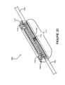
- FIG. 20is an example implementation of one or more portions of one or more systems described herein.
- Spinal fusionis a common form of surgical treatment for progressive scoliosis in adults and skeletally mature children. Spinal fusion usually involves placement of rods, hooks, pedicle screws, and/or bone grafts to correct the affected portion of the spine. However, this type of surgery can immobilize the treated sections of the spine.
- spinal fusion treatmentcan limit the potential growth of the child, which may lead to other potential health problems, such as thoracic insufficiency syndrome, in which reduced or halted growth of the thorax may fail to provide sufficient volume for healthy adult respiratory function.
- DGRdual growing rods
- VPTRvertical expandable prosthetic titanium rib
- rodscan be anchored to bones, including the spine, the rib, and/or the pelvis, and the rods are configured to be selectively lengthened.
- patients undergoing these treatmentstypically need repetitive surgical interventions to first implant, and subsequently lengthen the implants, sometimes as often as every four months.
- FIG. 1illustrates a perspective view of an example growing rod apparatus 100 .
- some existing growth rod devices used to treat scoliosis in humanscomprise a rod holder 102 , one or more growth rods 104 , 106 , and one or more pairs of set screws 108 , 110 used to secure the rod(s) 104 , 106 to the rod holder 102 .
- the set screws 108 , 110comprise a tool engagement opening 112 that is designed to receive a tool used to loosen and/or tighten the screw.
- a hex-toole.g., allen-wrench
- a hex-toolmay be inserted into the tool engagement opening 112 and rotated (e.g., clock-wise, counter clock-wise) to loosen and/or tighten the screw 108 , 110 .
- the patientneeds to undergo invasive surgery (e.g., be cut open).
- invasive surgerye.g., be cut open
- an open spinal surgerymay be needed every six months until the age of skeletal maturity.
- a severe psychosocial hurdlemay be imposed, particularly for the skeletally immature and their care givers.
- morbiditytypically arises from the need for repeated surgical intervention. Infections and skin-related complications may lead to additional surgeries, long term antibiotics therapy, and psychosocial stress from chronic hospitalization on both the patient and the care-giver.
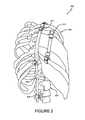
- FIG. 2illustrates a perspective view of one implementation 200 of an example of a growing rod apparatus.
- a first type of growing rod system 208may be engaged with (e.g., screwed into) a patient's spine 202 at a first end 206 , and with the patients ribcage 204 at a second end 210 .
- a desired orientation of the patient's spine 202may be obtained.
- the desired orientationmay be adjusted periodically, by surgically opening the patient and manually manipulating the device 208 , for example, in order to adjust the spine to a desired final orientation.
- a second type of growth rod system 212may be merely engaged with the patient's ribcage 204 ; however, manual manipulation via invasive surgery may still be needed.
- a non-invasive system and/or devicemay be devised that can provide a treatment for scoliosis, may allow for continued thoracic growth, and may mitigate repetitive surgical interventions.
- a systemmay utilize one or more rods respectively secured to a rod holder by one or more fasteners, where respective fasteners can be tightened and/or loosened by an external device (e.g., without surgical intrusion of the patient). That is, for example, a fastener can be coupled with a magnetic component that may be rotated by the external device. In this example, when the magnetic component rotates it may apply torque to the fastener, thereby tightening and/or loosening the fastener.
- the fastenermay be situated in the rod holder such that tightening the fastener can secure a corresponding rod, with respect to the rod holder.
- adjustment procedures for such a non-invasive devicemay be undertaken an exam room, for example, instead of an operating room.
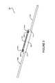
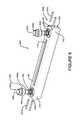
- the non-invasive tensioning system 300comprises a rod holder 308 comprising a first end 310 and a second end 312 .
- the rod holder 308is configured to selectively engage with a first rod 304 a .
- the non-invasive tensioning system 300comprises a first fastener 302 a disposed at the first end 310 .
- the first fastener 302 ais configured to secure the first rod 304 a with respect to the rod holder 308 . Additionally, the non-invasive tensioning system 300 comprises a first magnet component 602 a that is operably coupled with the first fastener 302 a . The first magnet component 602 a is configured to apply torque to the first fastener 302 a when it is subjected to a desired magnetic field.
- the non-invasive tensioning system 300can comprise a second fastener 302 b disposed at the second end 312 of the rod holder 308 .
- the second fastener 302 bcan be configured to secure a second rod 304 b with respect to said rod holder 308 .
- the second fastener 302 bmay be configured to secure the first rod 304 a to the rod holder 308 , for example, where the first rod 304 a extends from the first end 310 to the second end 312 of the rod holder (e.g., through an entire length of the rod holder 308 ).
- the non-invasive tensioning system 300can comprise a second magnet component 602 b , that is operably coupled with the second fastener 302 b .
- the second magnet component 602 bcan be configured to apply torque to the second fastener 302 b when it is subjected to the desired magnetic field.
- the fasteners 302may be rotated (e.g., loosened or tightened) by applying a desired magnetic field to the magnetic components 602 .
- a magnetic fieldmay induce a force upon certain components as described herein.
- the force induced by the magnetic fieldwill be referred to as magnetic force.
- the desired magnetic fieldcan comprise a magnetic field that provides a desired amount of magnetic force in a desired orientation, for example, that cause the fastener to rotate in a desired direction (e.g., clockwise, counter-clockwise).
- the rod holder 308 of the exemplary system/device 300can comprise a rod receiving shaft 506 , sleeve, tube or any aperture that is entirely hollow or partially hollow.
- the rod holder 308(e.g., as illustrated in FIGS. 8B and 8C ) can comprise a first rod receiving shaft 506 a with an opening at the first end 310 , where the first rod receiving shaft portion 506 a is configured to selectively engage the first rod 304 a .
- the rod holder 308can comprise a second rod receiving shaft portion 506 b with an opening at the second end 312 , where the second rod receiving shaft portion 506 b is configured to selectively engage the second rod 304 b.
- first rod receiving shaft portion 506 a and the second rod receiving shaft portion 506 bmay be disposed along a same shaft axis, for example, such that the first rod receiving shaft portion 506 a and second rod receiving shaft portion 506 b may form a continuous rod receiving shaft 506 through the rod holder 308 .
- An elongated slot 314can be disposed between the first end 310 and the second end 312 .
- first rod receiving shaft portion 506 a and the second rod receiving shaft portion 506 bmay intersect the elongated slot 314 , for example, such that the first rod 304 a and/or the second rod 304 b may be visible through an opening of the elongated slot 314 (e.g., to visibly determine a location of respective rods engaged in the shaft(s)).
- the first rod receiving shaft portion 506 amay lie along a first shaft axis and the second rod receiving shaft portion 506 b may lie along a second shaft axis.
- the first and second shaft axesmay be offset with respect to the rod holder 308 . That is, for example the first rod receiving shaft portion 506 a may run along the length of the rod holder 308 on a first side, while the second rod receiving shaft portion 506 b may run along the length of the rod holder 308 on a second side.
- first rod 304 acan engage the first rod receiving shaft portion 506 a
- second rod 304 bcan engage the second rod receiving shaft portion 506 b
- the two rodsmay not meet inside the rod holder, and they may extend completely through the length of the rod holder 308 .
- multiple fastenersmay be disposed at respective ends 310 , 312 of the rod holder 308 (e.g., as in FIG. 1 ). That is, for example, one or more additional fasteners can be disposed at the first end 310 , along with the first fastener 302 a . The one or more additional fasteners can also be configured to secure the first rod 304 a with respect to the rod holder 308 . Further, two or more second fasteners (e.g., the second fastener 302 b and one or more additional fasteners) can be disposed at the second end 312 , and can also be configured to secure the second rod 304 b with respect to the rod holder 308 .
- the second fastener 302 b and one or more additional fastenerscan be disposed at the second end 312 , and can also be configured to secure the second rod 304 b with respect to the rod holder 308 .
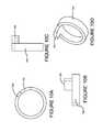
- respective fasteners 302may comprise screw head 306 , a screw shank 402 , and a threaded portion 404 .
- the threaded portion 404may be configured to be received by, and engage with, a threaded receiving portion 406 , for example, disposed in the rod holder 308 , such as at the first end 310 and/or the second end 312 .
- the magnet component 602may be operably coupled with the fastener 302 (e.g., such as at the screw shank 402 ), such that a north pole portion of the magnet component 602 resides at a first side 408 of the fastener 302 , and a south pole portion of the magnet component 602 resides at a second side 410 of the fastener 302 .
- a north pole magnetic force applied to the first side 408 of the fastener 302may cause the fastener 302 to rotate in a desired direction; and a south pole magnetic force applied to the second side 410 of the fastener 302 , may cause the fastener 302 to continue to rotate in the desired direction.
- the application of the north pole and the south pole forceis continuously alternated (e.g., rotationally), the fastener 302 may continue to rotate in the desired direction.
- the magnet component 602may be disposed in rotational engagement with at least a portion of the fastener 302 .
- the first magnet component 602 amay be rotationally engaged with the screw shank 402 of the first fastener 302 a
- the second magnet componentmay be rotationally engaged with the screw shank 402 of the second fastener 302 b .
- the geometry of the fastener(s) 302may be any form chosen with sound engineering judgment.
- the screw shank 402may comprise a cylinder form.
- the fastener 302can comprise an interior portion 902 , in which the magnet component 602 may be disposed, in rotational engagement with the fastener's shank 402 .
- the magnet component 602(e.g., comprising one or more magnets) may be free floating or seated inside the interior portion 902 , such that they are not fixedly engaged with any portion of the interior 902 .
- the magnet component 602as illustrated in FIGS. 11A and 11B , comprising opposite north 1102 and south 1104 poles, may freely rotate inside the interior portion 902 when subjected to the desired magnetic field, as described above.
- the fastenermay comprise a magnet engaging component 904 , such as an extension disposed in the interior portion 902 of the screw shank 402 , that is engaged with the first fastener.
- the magnet engaging component 904may be formed with the fastener 302 ; and in another implementation, the magnet engaging component 904 may be attached to the fastener 302 .
- the magnet engaging component 904can be configured to selectively engage with the magnet component 602 , such that an application of torque to the first magnet component 602 that is engaged with the magnet engaging component 904 causes torque to be applied to the fastener 302 .
- the magnet component 602may comprise a collar extension 702 , which extends from a magnet collar 704 fixedly engaged with the magnet component 602 .
- the magnet collar component 704may comprise an annular shape configured to merely fit around the magnet component 602 in fixed engagement.
- the magnet collar component 704may be formed with the magnet component 602 ; in another implementation the magnet collar component 704 may be attached (e.g., press fit, adhered, glued, welded, soldered, etc.) to the magnet component 602 .
- the magnet collar component 704can comprise the collar extension 702 , which is configured to be disposed in opposing engagement with respect to the interior extension 904 disposed in the interior portion 902 of the screw shank 402 .
- the magnet component 602can rotate (e.g., in a direction dependent on the rotation of the desired magnetic field, as described above), and the collar extension 702 can engage the interior extension portion 904 of the fastener 302 , which may cause the fastener 302 to rotate in the same direction of rotation.
- the interior portion 902may comprise a track for the magnet component (e.g., and/or magnet collar 704 ) to improve engagement of the collar extension 704 with magnet engaging component 904 (e.g., interior portion extension), in order to provide the appropriate torque to the fastener 302 .
- the magnet component 602when the magnetic force provided by the desired magnetic field causes the magnet component 602 (e.g., the collar extension 704 of the magnet collar 702 ) to engage the magnet engaging component 904 of the fastener 302 , the magnet component 602 may rebound (e.g., bounce back from engagement), depending on an amount of rotational resistance extant for the fastener.
- the magnet component 602upon the magnet component 602 disengaging (e.g., bouncing away from) the magnet engaging component 904 , when the fastener encounters a certain amount of rotational resistance (e.g., stops rotating), the magnet component 602 can re-engage the magnet engaging component 904 , when the magnet component 602 is subjected to the desired magnetic field.
- a rotational hammering forcemay be applied to the fastener 302 .
- the magnetic force provided by the desired magnetic fieldcan be re-applied to the magnet component 602 , causing it to re-contact the collar extension 702 of the magnet collar 704 within the screw shank 402 of the fastener 302 .
- a repeated bounce-back and re-engagement actioncan cause a type of hammering effect between the collar extension 702 and the magnet engaging component 904 (e.g., the interior extension of the screw shank 402 ). It may be the hammering action, for example, that can cause the fastener 302 to rotate, particularly when subjected to rotational resistance. In this way, for example, a loose screw may be tightened more effectively, and a tight screw may be loosened more effectively.
- a screw cap 604may be operatively coupled with the fastener 302 , for example, with the magnet component 602 positioned therebetween, as illustrated in FIGS. 6 and 7 .
- the screw shank 402may comprise a blunt end disposed at an end portion of the threaded portion 404 . The blunt end may be engaged with the screw cap 604 , such as by pressure fitting.
- the blunt end engaged with the screw cap 604may be configured to apply pressure to a rod 304 inserted into the rod holder 308 (e.g., when the threaded portion is tightened down), such that the rod 304 may be secured (e.g., to a desired tensioning force) within the rod receiving shaft 506 of the rod holder 308 .
- a first screw stop component 508 amay disposed in the first end 310 , and/or a second screw stop component 508 b may disposed in the second end 312 of the rod holder 308 .
- the screw stop component 508may be configured to mitigate over-rotation of the fastener 302 , past a desired setting.
- the screw stop component 508can comprise a stop receiver 502 , comprising a tube disposed in the rod holder, and a stop pin 504 , configured to be selectively engaged with the stop receiver 502 .
- the stop pin 504may be inserted into the stop receiver 502 after the fastener 302 is inserted into a fastener receiving hole 802 of the rod holder 308 .
- a portion of the screw head 306may engage the stop pin 504 when the fastener 302 is loosened (e.g., rotated out), preventing the fastener 302 from rotating past the position of the stop pin 504 .
- the screw stop component 508may mitigate inadvertently unscrewing the fastener completely from the fastener receiving hole 802 , thereby becoming disengaged from the rod holder 308 .
- the screw stop component 508may comprise any mechanical stop chosen with sound engineering judgment.
- the screw stop component 508may be internal to the rod holder 308 , as illustrated in FIG. 5 , and/or it may be external to the rod holder 308 .
- the screw stop component 508may be integrated with the fastener 302 itself, and/or may be fastened to the interior or exterior of the fastener 302 .
- the rod holder 308may comprise a first screw receiving hold 802 a and a second screw receiving hold 802 b .
- the screw receiving hole(s)may be configured to receive a fastener 302 , such as a set screw. It is anticipated that alternate configurations of the rod holder/fastener configuration may be designed by those skilled in the art.
- a rod holdermay comprise a type of rod clamp 1402 , where a set screw-type fastener 302 may be utilized to secure one or more rods in respective rod holding shafts 1404 .
- one or more portions of the fastener 302 and/or fastener receiving hole 802may be encapsulated with a suitable (e.g., medically inert) material.
- the magnet component 602can be encapsulated within fastener 302 , for example, to mitigate corrosion of the magnet component 602 .
- the screw cap 604may seal the magnet component 602 inside the interior portion 902 of the screw shank 402 .
- encapsulation of the entire non-invasive tensioning device 300may mitigate formation of undesirable materials on working parts of the device 300 , for example, which may interfere with the ability of the threaded portion 404 to effectively engage with the screw receiving hold 802 of the rod holder 308 .
- a first fastener 302 amay be inserted in a first screw receiving hole 802 a
- a second fastener 302 bmay be inserted into a second screw receiving hold 802 b
- the first and/or second fasteners 302may comprise set screws, for example, where a set screw may comprise a flat or relatively blunt end, configured to engage a rod 304 , to secure the rod 304 against the rod holder 308 using pressure.
- the set screwmay comprise a pointed or relatively pointed end, configured to engage an indentation, hole, valley, notch, or other set screw receiving cut-out, of the rod 304 .
- the rod 304may comprise a plurality of rod positioning elements (e.g., indentations, holes, valleys, notches, etc.) respectively configured to facilitate securing of the rod with respect to said rod holder at a desired position.
- the rod positioning elementsmay be disposed at locations along the rod suitable for adjusting the rod with respect to the desired scoliosis treatment.
- the respective one or more rodsmay comprise a plurality of indentations respectively disposed at a desired interval, and/or a plurality of rises respectively disposed at a desired interval, where the indentations and/or valleys between the rises may selectively engage the set screw, and help secure the rod 304 in the rod holder 308 .
- the rod 304may comprise one or more teeth that are configured to engage corresponding teeth disposed in the rod holder 308 .
- the teeth on the rod 304may engage the teeth in the rod holder 308 to provide a type of ratcheting adjustment system, where the rod may be selectively adjusted according to desired ratcheting positions of the teeth.
- a first stop pin 504 amay be engaged with (e.g., inserted into) a first stop receiver 504 a
- a second stop pin 504 bmay be engaged with a second stop receiver 504 b .
- the fastener(s)may not be inadvertently disengaged from the rod holder 308 .
- a first growing rod 304 amay be inserted into the first rod receiving shaft 506 a of the rod holder 308 , and a second growing rod 304 a may be inserted into the second rod receiving shaft 506 b of the rod holder 308 .
- the first and/or second growing rods 304may be selectively fastened to bone, such as a portion of the spine and/or ribcage.
- the rod holder 308may be selectively fastened to bone (e.g., in a human), for example, such as using the rod clamp of FIG. 14 .
- the patientmay be surgically closed.
- a magnetic field generation component 1502may be utilized.
- the magnetic field generation component 1502can comprise one or more actuation magnets 1604 , and an axle 1602 operably coupled with the one or more actuation magnets 1604 .
- the axle 1602may be configured to cause the actuation magnet(s) 1604 to rotate around an axis of magnet rotation to generate the desired magnetic field.
- the rotating magnetscan provide the magnetic force needed to rotate the fastener, when brought in close proximity to the magnet component 602 disposed in the fastener 302 .
- a first actuation magnet 1604 amay comprise a north pole disposed its outward facing end
- a second actuation magnet 1604 bmay comprise a south pole disposed its outward facing end
- a third actuation magnet 1604 cmay comprise a north pole disposed its outward facing end
- a fourth actuation magnet 1604 dmay comprise a south pole disposed its outward facing end.
- an alternating north-south magnetic forcemay be provided at a face of the magnetic field generation component 1502 .
- the magnetic field generation component 1502can comprise a housing 1606 , a face of which may be placed proximate to a location of a fastener 302 in the non-invasive tensioning device 300 disposed in the patient.
- the alternating north-south magnetic forcecan be provided at the housing face, which may cause the fastener 302 to rotate (e.g., non-invasively), as described above.
- the one or more magnets 1604 of the magnetic field generation component 1502can be rotated in a first direction (e.g., clockwise), for example, causing rotational torque to be applied to a fastener 302 in the first direction.
- the one or more magnets 1604 of the magnetic field generation component 1502can be rotated in a second direction (e.g., counter-clockwise), for example, causing rotational torque to be applied to the fastener 302 in the second direction.
- an orientation of the magnetic field generation component 1502 with respect to a rotating magnetic component, disposed adjacent,may determine whether the adjacent rotating magnetic component is affected by the resulting magnetic field. For example, where two rotating magnetic components are disposed relatively perpendicular to each other (e.g., disposed on a growing rod apparatus in a patient), placing the magnetic field generation component 1502 in a first orientation, with respect to the rotating magnetic components, may cause rotational torque to be applied to merely a first one of the rotating magnetic components. In this example, placing the magnetic field generation component 1502 in a second orientation, with respect to the rotating magnetic components, may cause rotational torque to be applied to merely a second one or the rotating magnetic components, and not to the first.
- an appropriate orientation of the magnetic field generation component 1502may be used such that the desired fastener is affected by the resulting magnetic field, and not non-desired fasteners.
- the action of the magnetic force from the magnetic field generation component 1502can produce a hammering force, as described above.
- the magnet component 602may rotate in a one to one revolution relative to the screw shank 402 and threaded portion 404 until rotational resistance is encountered, such as from a tightening against the growing rod 304 , or against the screw stop component 508 .
- the magnet component 602may not rotate at the same speed as the screw shank 402 and threaded portion 404 . That is, for example, the magnets component 602 may have a greater velocity than the screw shank 402 .
- respective turns of the magnet component 602may attempt to rotate the screw shank 402 one revolution. However, if rotational resistance is encountered, the fastener 302 may not turn an entire revolution.
- the magnetic field generation component 1502may be used to loosen the fastener(s) securing the one or more tensioning rods 304 .
- the magnetic field generation component 1502can be placed in close proximity to the patient, and rotated (e.g., manually or by a powered rotation source, such as a powered screwdriver, drill, etc.). Further, the rotation can be applied in a direction that causes the magnet component 602 to rotate (e.g., in a clockwise direction) within the fastener 302 , in a fashion that produces torque, for example. As described above, the torque can cause the fastener 302 to rotate (e.g., loosen).
- non-invasive tensioning devicemay comprise a fastener locking component configured to mitigate loosening of the fastener 302 from secure engagement with the rod 304 .
- meansmay be used to measure the change in position of the rods.
- any means chosen with sound engineering judgmentmay be applied.
- the use of beads (not shown) on the growing rodsmay be used, which can be detected using a non-invasive scan, such as CT scan, fluoroscopy, or other noninvasive means.
- electromagnetic meansmay be used to determine a distance of distraction, such as during adjustment.
- a sensing meanse.g., sensor device
- a polarity change of a rotating magnetic componentsuch magnetic drive screw.
- a polarity change of the rotating magnetic componentmay indicate particular amount of rotation (e.g., one rotation) of the rotating magnetic component. This may further indicate a distance traveled by combining the amount of rotation with a thread distance to determine how far the component travels per rotation, for example.
- a control devicemay be used to limit an amount of rotation (e.g., and distance traveled) of the rotating magnetic component (e.g., fastener and/or drive screw), for example, by mitigating the effects of the magnetic force applied to the rotating magnetic component when a predetermined amount of rotation (e.g., and/or distance traveled) has been met.
- a physicianmay indicate that the magnetic drive screw can be adjusted by five millimeters.
- the control devicemay shut off the magnetic force generation component (e.g., or shield the magnetic drive screw from the magnetic force) upon the sensing means identifying that the magnetic drive screw has traveled the desired five millimeters. In this way, for example, the desired distraction may be applied, while mitigating a chance that the growing rods may be over or under distracted.
- the device 300may be removed from the pediatric patient upon reaching orthopedic maturity such that a different implant system could be utilized to fuse the spine as needed.
- the device 300may be adaptable such that the rotating magnet 36 will not need to be utilized to loosen it.
- the magnet 36 of the devicemay be loosened with a wrench or set screw driver and external surgical instruments to remove it and provides increased flexibility and adaptation to benefit the patient.
- One significant difference from the prior artis the absence of a drive mechanism inside the shaft 20 . There is no complicated gearing, springs, batteries, or other components to operate the present invention.
- the present inventionwhile described in detail for application with scoliosis can be applied to a variety of orthopaedic applications including but not limited to, any application where set screws are utilized.
- Non-limiting examplesmay include the set screws being utilized in conjunction with bone plates, bone rods, or other screws. It can be used to treat a variety of conditions including without limitation, fractures or any bone deformity.
- FIGS. 17-20another implementation of an exemplary growth rod apparatus 1700 is shown in FIGS. 17-20 .
- one or more growing rods 1702may be adjusted by a device method similar to that described above, such as a magnetic field generation component (e.g., 1502 in FIG. 15 ).
- a rod holder 1704may be provided (e.g., such as 308 of FIG. 3 ), for example, configured to hold the one or more growing rods 1702 .
- a first magnet-based set screw 1706such as described above (e.g., 302 of FIG. 3 ), may be rotationally engaged with a first end of the rod holder 1708 , and configured to selectively engage the growing rod 1702 , for example, when rotated down into the rod holder 1704 .
- a second magnet-based set screw 1710may be rotationally engaged with a second end of the rod holder 1712 , and configured to selectively engage the growing rod 1702 , for example, when rotated down into the rod holder 1704 .
- a shaft portion 1714 of the rod holder 1704which may be engaged with one or more of the growing rods 1702 can comprise internal threading (e.g., female threading).
- a magnetic drive screw 1716may be disposed in the shaft portion 1714 .
- the magnetic drive screw 1716may comprise a drive magnet 1718 (e.g., similar to 602 of FIG. 6 ) disposed therein.
- the drive magnet 1718can be configured to be driven (e.g., rotated) using an external drive device, such as the magnetic field generation component described above (e.g., 1502 in FIG. 15 ), in a manner similar to that described above in FIGS. 2-16 .
- a magnet collar(e.g., 702 of FIG. 7 ) may be fixedly attached to the drive magnet 1718 , and the magnetic drive screw 1716 may comprise an internal magnet engaging component (e.g., 904 of FIG. 9A ) disposed in opposing rotational engagement with the magnet collar of the drive magnet 1718 .
- the magnet collar of the drive magnet 1718may apply rotational force to the magnet engaging component inside the magnetic drive screw 1716 , for example, thereby causing the magnetic drive screw 1716 to rotate in accordance with the applied rotational magnetic force.
- the magnetic drive screw 1716may comprise external threading (e.g., male threading) that is configured to threadedly engage the internal threading of the shaft portion 1714 of the rod holder 1704 .
- magnetically rotating the magnetic drive screw 1716may cause the magnetic drive screw 1716 to travel along the shaft portion 1714 of the rod holder 1704 , with the direction of travel dependent upon a direction of rotation of the magnetic drive screw 1716 (e.g., and therefore the rotation and/or orientation of the magnetic force generation component 1502 ).
- one or more of the growing rods 1702may be engaged with the shaft portion 1714 , for example, and secured in the rod holder 1704 by means of the first and/or second fasteners 1706 , 1710 .
- the magnetic drive screw 1716may be used to extend the growing rod 1702 .
- the magnetic drive screw 1716can be magnetically rotated to cause the magnetic drive screw 1716 to engage an end of the growing rod 1702 disposed in the shaft portion 1714 , such that the magnetic drive screw 1716 pushes at least a portion of the growing rod 1702 out of the shaft portion 1714 .
- the fastener 1706may then be tightened (e.g., magnetically) to secure the growing rod 1702 in the rod holder 1704 at a desired position.
- the growing rod 1702may translate in the rod holder 1704 between about 5 mm and about 20 mm per adjustment.
- the one or more magnetic set screws 1706 , 1710can be loosened with the magnetic field generation component (e.g., 1502 in FIG. 15 , in an appropriate orientation), which may cause the growing rod 1702 to loosen with respect to the rod holder 1704 .
- the magnetic field generation componentcan actuate the magnetic drive screw 1716 , rotating the magnetic drive screw 1716 within the shaft portion 1714 of the rod holder 1704 .
- the magnetic drive screw 1716can apply force to the growing rod 1702 , for example, thereby causing the growing rod 1702 to advance a desired distance in the rod holder 1704 .
- the one or more magnetic set screws 1706 , 1710may be tightened with the magnetic field generation component, securing the growing rod(s) 1702 in the rod holder 1704 .
- any devices and methodology chosen with sound engineering judgmentmay be utilized to obtain the desired distance of travel of the growing rod within the rod holder as long as the magnetic drive screw 1716 is directly or indirectly engaged with the growing rod 1702 , and the drive magnet 1718 is actuated by the magnetic field generation component 1502 .
- exemplaryis used herein to mean serving as an example, instance or illustration. Any aspect or design described herein as “exemplary” is not necessarily to be construed as advantageous over other aspects or designs. Rather, use of the word exemplary is intended to present concepts in a concrete fashion.
- the term “or”is intended to mean an inclusive “or” rather than an exclusive “or.” That is, unless specified otherwise, or clear from context, “X employs A or B” is intended to mean any of the natural inclusive permutations. That is, if X employs A; X employs B; or X employs both A and B, then “X employs A or B” is satisfied under any of the foregoing instances.
- At least one of A and B and/or the likegenerally means A or B or both A and B.
- the articles “a” and “an” as used in this application and the appended claimsmay generally be construed to mean “one or more” unless specified otherwise or clear from context to be directed to a singular form.
Landscapes
- Health & Medical Sciences (AREA)
- Orthopedic Medicine & Surgery (AREA)
- Surgery (AREA)
- Life Sciences & Earth Sciences (AREA)
- Neurology (AREA)
- Engineering & Computer Science (AREA)
- Nuclear Medicine, Radiotherapy & Molecular Imaging (AREA)
- Biomedical Technology (AREA)
- Heart & Thoracic Surgery (AREA)
- Medical Informatics (AREA)
- Molecular Biology (AREA)
- Animal Behavior & Ethology (AREA)
- General Health & Medical Sciences (AREA)
- Public Health (AREA)
- Veterinary Medicine (AREA)
- Electromagnetism (AREA)
- Physics & Mathematics (AREA)
- Surgical Instruments (AREA)
Abstract
Description
Claims (11)
Priority Applications (3)
| Application Number | Priority Date | Filing Date | Title |
|---|---|---|---|
| US13/712,387US9949761B2 (en) | 2011-12-12 | 2012-12-12 | Noninvasive device for adjusting fastener |
| US14/303,169US10016226B2 (en) | 2011-12-12 | 2014-06-12 | Noninvasive device for adjusting fastener |
| US15/808,454US10675064B2 (en) | 2011-12-12 | 2017-11-09 | Distraction Osteogenesis system |
Applications Claiming Priority (3)
| Application Number | Priority Date | Filing Date | Title |
|---|---|---|---|
| US201161569453P | 2011-12-12 | 2011-12-12 | |
| US201261585450P | 2012-01-11 | 2012-01-11 | |
| US13/712,387US9949761B2 (en) | 2011-12-12 | 2012-12-12 | Noninvasive device for adjusting fastener |
Related Child Applications (1)
| Application Number | Title | Priority Date | Filing Date |
|---|---|---|---|
| US14/303,169Continuation-In-PartUS10016226B2 (en) | 2011-12-12 | 2014-06-12 | Noninvasive device for adjusting fastener |
Publications (2)
| Publication Number | Publication Date |
|---|---|
| US20130150889A1 US20130150889A1 (en) | 2013-06-13 |
| US9949761B2true US9949761B2 (en) | 2018-04-24 |
Family
ID=47520258
Family Applications (1)
| Application Number | Title | Priority Date | Filing Date |
|---|---|---|---|
| US13/712,387Active2034-06-02US9949761B2 (en) | 2011-12-12 | 2012-12-12 | Noninvasive device for adjusting fastener |
Country Status (10)
| Country | Link |
|---|---|
| US (1) | US9949761B2 (en) |
| EP (1) | EP2790600B1 (en) |
| JP (1) | JP6265911B2 (en) |
| CN (1) | CN104010583B (en) |
| AU (1) | AU2012352418B2 (en) |
| CA (1) | CA2859166C (en) |
| DK (1) | DK2790600T3 (en) |
| ES (1) | ES2629056T3 (en) |
| PT (1) | PT2790600T (en) |
| WO (1) | WO2013090345A1 (en) |
Cited By (4)
| Publication number | Priority date | Publication date | Assignee | Title |
|---|---|---|---|---|
| US20200187993A1 (en)* | 2018-12-18 | 2020-06-18 | Frank J. Schwab | Technologies for lines coupled to spines |
| US11065037B2 (en) | 2016-05-19 | 2021-07-20 | Auctus Surgical, Inc. | Spinal curvature modulation systems and methods |
| US12262917B2 (en) | 2016-05-19 | 2025-04-01 | Auctus Surgical, Inc. | Spinal curvature modulation systems and methods |
| US12310629B2 (en) | 2021-02-10 | 2025-05-27 | Alphatec Spine, Inc. | Methods and devices for augmenting the spine |
Families Citing this family (52)
| Publication number | Priority date | Publication date | Assignee | Title |
|---|---|---|---|---|
| US7955357B2 (en) | 2004-07-02 | 2011-06-07 | Ellipse Technologies, Inc. | Expandable rod system to treat scoliosis and method of using the same |
| US7862502B2 (en) | 2006-10-20 | 2011-01-04 | Ellipse Technologies, Inc. | Method and apparatus for adjusting a gastrointestinal restriction device |
| US20090112262A1 (en) | 2007-10-30 | 2009-04-30 | Scott Pool | Skeletal manipulation system |
| US11202707B2 (en) | 2008-03-25 | 2021-12-21 | Nuvasive Specialized Orthopedics, Inc. | Adjustable implant system |
| US11241257B2 (en) | 2008-10-13 | 2022-02-08 | Nuvasive Specialized Orthopedics, Inc. | Spinal distraction system |
| US8382756B2 (en) | 2008-11-10 | 2013-02-26 | Ellipse Technologies, Inc. | External adjustment device for distraction device |
| US8197490B2 (en) | 2009-02-23 | 2012-06-12 | Ellipse Technologies, Inc. | Non-invasive adjustable distraction system |
| US9622792B2 (en) | 2009-04-29 | 2017-04-18 | Nuvasive Specialized Orthopedics, Inc. | Interspinous process device and method |
| US8876867B2 (en) | 2009-06-24 | 2014-11-04 | Zimmer Spine, Inc. | Spinal correction tensioning system |
| JP5751642B2 (en) | 2009-09-04 | 2015-07-22 | エリプス テクノロジーズ, インク.Ellipse Technologies, Inc. | Bone growth apparatus and method |
| US9248043B2 (en) | 2010-06-30 | 2016-02-02 | Ellipse Technologies, Inc. | External adjustment device for distraction device |
| WO2012021378A2 (en) | 2010-08-09 | 2012-02-16 | Ellipse Technologies, Inc. | Maintenance feature in magnetic implant |
| WO2012112396A2 (en) | 2011-02-14 | 2012-08-23 | Ellipse Technologies, Inc. | Device and method for treating fractured bones |
| US10743794B2 (en) | 2011-10-04 | 2020-08-18 | Nuvasive Specialized Orthopedics, Inc. | Devices and methods for non-invasive implant length sensing |
| US10016220B2 (en) | 2011-11-01 | 2018-07-10 | Nuvasive Specialized Orthopedics, Inc. | Adjustable magnetic devices and methods of using same |
| US10016226B2 (en) | 2011-12-12 | 2018-07-10 | Children's Hospital Medical Center Of Akron | Noninvasive device for adjusting fastener |
| US9949761B2 (en) | 2011-12-12 | 2018-04-24 | Children's Hospital Medical Center Of Akron | Noninvasive device for adjusting fastener |
| US9427261B2 (en)* | 2012-06-13 | 2016-08-30 | Warsaw Orthopedic, Inc. | Spinal correction system and method |
| US20130338714A1 (en) | 2012-06-15 | 2013-12-19 | Arvin Chang | Magnetic implants with improved anatomical compatibility |
| US9044281B2 (en) | 2012-10-18 | 2015-06-02 | Ellipse Technologies, Inc. | Intramedullary implants for replacing lost bone |
| EP2911616B1 (en) | 2012-10-29 | 2020-10-07 | NuVasive Specialized Orthopedics, Inc. | Adjustable devices for treating arthritis of the knee |
| US9179938B2 (en) | 2013-03-08 | 2015-11-10 | Ellipse Technologies, Inc. | Distraction devices and method of assembling the same |
| US10226242B2 (en) | 2013-07-31 | 2019-03-12 | Nuvasive Specialized Orthopedics, Inc. | Noninvasively adjustable suture anchors |
| US9801734B1 (en) | 2013-08-09 | 2017-10-31 | Nuvasive, Inc. | Lordotic expandable interbody implant |
| US10751094B2 (en) | 2013-10-10 | 2020-08-25 | Nuvasive Specialized Orthopedics, Inc. | Adjustable spinal implant |
| US9486252B2 (en)* | 2014-01-09 | 2016-11-08 | Warsaw Orthopedic, Inc. | Spinal correction system and method |
| CN106456215B (en) | 2014-04-28 | 2020-04-10 | 诺威适骨科专科公司 | External adjustment device for adjusting a medical implant |
| US9872709B2 (en)* | 2014-05-23 | 2018-01-23 | Warsaw Orthopedic, Inc. | Spinal correction construct and method |
| US9931138B2 (en)* | 2014-10-15 | 2018-04-03 | Globus Medical, Inc. | Orthopedic extendable rods |
| KR102588501B1 (en) | 2014-10-23 | 2023-10-11 | 누베이시브 스페셜라이즈드 오소페딕스, 인크. | Remotely adjustable interactive bone reshaping implant |
| US9980757B2 (en)* | 2014-12-01 | 2018-05-29 | Ebi, Llc | Anchor and rod connector |
| ES2908064T3 (en) | 2014-12-26 | 2022-04-27 | Nuvasive Specialized Orthopedics Inc | distraction systems |
| CA2917676A1 (en) | 2015-01-13 | 2016-07-13 | Stryker European Holdings I, Llc | Growing rods and methods of use |
| US10238427B2 (en) | 2015-02-19 | 2019-03-26 | Nuvasive Specialized Orthopedics, Inc. | Systems and methods for vertebral adjustment |
| US10226281B2 (en)* | 2015-10-05 | 2019-03-12 | Globus Medical, Inc. | Growing rod for treating spinal deformities and method for using same |
| BR112018007347A2 (en) | 2015-10-16 | 2018-10-23 | Nuvasive Specialized Orthopedics, Inc. | adjustable devices for the treatment of knee arthritis |
| CN108601611B (en) | 2015-12-10 | 2021-11-02 | 诺威适骨科专科公司 | External adjustment device for stretcher |
| BR112018015504A2 (en) | 2016-01-28 | 2018-12-18 | Nuvasive Specialized Orthopedics, Inc. | bone transport systems |
| WO2017139548A1 (en) | 2016-02-10 | 2017-08-17 | Nuvasive Specialized Orthopedics, Inc. | Systems and methods for controlling multiple surgical variables |
| WO2018102101A2 (en) | 2016-11-09 | 2018-06-07 | Children's Hospital Medical Center Of Akron | Distraction osteogenesis system |
| US10206719B2 (en) | 2016-12-16 | 2019-02-19 | Nuvasive, Inc. | Bone hook apparatus |
| US11446064B2 (en) | 2018-04-26 | 2022-09-20 | Stryker European Operations Holdings Llc | Orthopedic growing devices |
| US10835292B2 (en) | 2018-06-13 | 2020-11-17 | Nuvasive, Inc. | Rib fixation device and related methods |
| JP2022519380A (en) | 2019-02-07 | 2022-03-23 | ニューベイシブ スペシャライズド オーソペディックス,インコーポレイテッド | Ultrasonic communication in medical devices |
| US11589901B2 (en) | 2019-02-08 | 2023-02-28 | Nuvasive Specialized Orthopedics, Inc. | External adjustment device |
| CN110593129B (en)* | 2019-10-14 | 2021-01-22 | 济南鑫顺莉贸易有限公司 | Waterproof fastening device is used in public road bridge roof beam construction |
| CN111588454A (en)* | 2020-05-27 | 2020-08-28 | 安生健康科技(天津)有限公司 | Internal automatic growth rod for treating early-onset scoliosis of children |
| US12213708B2 (en) | 2020-09-08 | 2025-02-04 | Nuvasive Specialized Orthopedics, Inc. | Remote control module for adjustable implants |
| US20220265326A1 (en) | 2021-02-23 | 2022-08-25 | Nuvasive Specialized Orthopedics, Inc. | Adjustable implant, system and methods |
| US11737787B1 (en) | 2021-05-27 | 2023-08-29 | Nuvasive, Inc. | Bone elongating devices and methods of use |
| US20240358412A1 (en)* | 2021-06-25 | 2024-10-31 | Nuvasive Specialized Orthopedics, Inc. | Adjustable implant, system and methods |
| EP4380480A1 (en) | 2021-08-03 | 2024-06-12 | NuVasive Specialized Orthopedics, Inc. | Adjustable implant |
Citations (55)
| Publication number | Priority date | Publication date | Assignee | Title |
|---|---|---|---|---|
| USRE24066E (en)* | 1955-10-04 | Magnetic fastener-holding device | ||
| US5575790A (en) | 1995-03-28 | 1996-11-19 | Rensselaer Polytechnic Institute | Shape memory alloy internal linear actuator for use in orthopedic correction |
| US5704939A (en) | 1996-04-09 | 1998-01-06 | Justin; Daniel F. | Intramedullary skeletal distractor and method |
| DE19807663A1 (en) | 1998-02-24 | 1999-09-09 | Baur | Connection means for releasably connecting a first component and a second component and method for releasing a connection of a first component and a second component |
| US6004349A (en)* | 1997-01-06 | 1999-12-21 | Jackson; Roger P. | Set screw for use with osteosynthesis apparatus |
| US6033412A (en) | 1997-04-03 | 2000-03-07 | Losken; H. Wolfgang | Automated implantable bone distractor for incremental bone adjustment |
| DE20013178U1 (en) | 2000-07-29 | 2000-10-26 | Baur, Franz, 87534 Oberstaufen | Connection means for releasably connecting a first component and a second component |
| US6514255B1 (en)* | 2000-02-25 | 2003-02-04 | Bret Ferree | Sublaminar spinal fixation apparatus |
| US20040030395A1 (en) | 2000-04-13 | 2004-02-12 | Gordon Blunn | Surgical distraction device |
| WO2004019796A1 (en) | 2002-08-30 | 2004-03-11 | Arnaud Soubeiran | Implantable mechanical device with adjustable geometry |
| US20040236329A1 (en) | 2003-05-02 | 2004-11-25 | Panjabi Manohar M. | Dynamic spine stabilizer |
| US20040254575A1 (en) | 2003-06-13 | 2004-12-16 | Obenchain Theodore G. | Method and apparatus for stabilization of facet joint |
| US20050090827A1 (en)* | 2003-10-28 | 2005-04-28 | Tewodros Gedebou | Comprehensive tissue attachment system |
| US20060047282A1 (en)* | 2004-08-30 | 2006-03-02 | Vermillion Technologies, Llc | Implant for correction of spinal deformity |
| US20060058792A1 (en)* | 2004-09-16 | 2006-03-16 | Hynes Richard A | Intervertebral support device with bias adjustment and related methods |
| US20060074448A1 (en) | 2004-09-29 | 2006-04-06 | The Regents Of The University Of California | Apparatus and methods for magnetic alteration of deformities |
| US20060079897A1 (en) | 2004-09-29 | 2006-04-13 | Harrison Michael R | Apparatus and methods for magnetic alteration of anatomical features |
| US20060229615A1 (en)* | 2005-02-18 | 2006-10-12 | Abdou M S | Devices and methods for dynamic fixation of skeletal structure |
| US20070233098A1 (en)* | 2004-06-30 | 2007-10-04 | Brooke Mastrorio | Adjustable Posterior Spinal Column Positioner |
| WO2007118179A2 (en) | 2006-04-06 | 2007-10-18 | Synthes (U.S.A.) | Remotely adjustable tissue displacement device |
| US20070276378A1 (en) | 2004-09-29 | 2007-11-29 | The Regents Of The University Of California | Apparatus and methods for magnetic alteration of anatomical features |
| US20080027436A1 (en)* | 2006-07-14 | 2008-01-31 | John Cournoyer | Rod to Rod Connectors and Methods of Adjusting The Length Of A Spinal Rod Construct |
| US20080033436A1 (en) | 2004-08-30 | 2008-02-07 | Vermillion Technologies, Llc | Device and method for treatment of spinal deformity |
| WO2008135250A2 (en) | 2007-05-08 | 2008-11-13 | Lamello Ag | Connection means and method for connecting a first component and a second component |
| US20090005821A1 (en)* | 2007-06-29 | 2009-01-01 | Spineworks Medical, Inc. | Methods and devices for stabilizing bone compatible for use with bone screws |
| US20090012565A1 (en) | 2007-06-06 | 2009-01-08 | Vertech, Inc. | Medical device and method to correct deformity |
| DE202008016179U1 (en) | 2007-05-08 | 2009-03-05 | Baur, Franz, Dipl.-Ing. | Connecting means for establishing a connection of a first component and a second component |
| US20090082815A1 (en)* | 2007-09-20 | 2009-03-26 | Zimmer Gmbh | Spinal stabilization system with transition member |
| US20090112263A1 (en) | 2007-10-30 | 2009-04-30 | Scott Pool | Skeletal manipulation system |
| CN101466321A (en) | 2006-04-06 | 2009-06-24 | 新特斯有限责任公司 | Remotely adjustable tissue displacement device |
| US20090198279A1 (en)* | 2008-02-02 | 2009-08-06 | Texas Scottish Rite Hospital For Children | Spinal Rod Link Reducer |
| US20090198273A1 (en)* | 2008-02-02 | 2009-08-06 | Texas Scottish Rite Hospital For Children | Pedicle Screw |
| US20090204154A1 (en) | 2004-07-02 | 2009-08-13 | Ellipse Technologies, Inc. | expandable rod system to treat scoliosis and method of using the same |
| US7650888B2 (en) | 2006-02-22 | 2010-01-26 | Siemens Aktiengesellschaft | Method and system for identification of a medical implant |
| US20100094306A1 (en) | 2008-10-13 | 2010-04-15 | Arvin Chang | Spinal distraction system |
| US20100114103A1 (en) | 2008-11-06 | 2010-05-06 | The Regents Of The University Of California | Apparatus and methods for alteration of anatomical features |
| US20100121323A1 (en) | 2008-11-10 | 2010-05-13 | Ellipse Technologies, Inc. | External adjustment device for distraction device |
| US20100137911A1 (en)* | 2008-12-03 | 2010-06-03 | Zimmer Spine, Inc. | Adjustable Assembly for Correcting Spinal Abnormalities |
| US7753915B1 (en)* | 2007-06-14 | 2010-07-13 | August Eksler | Bi-directional bone length adjustment system |
| US20100217271A1 (en) | 2009-02-23 | 2010-08-26 | Ellipse Technologies, Inc. | Spinal distraction system |
| DE102009042844A1 (en) | 2009-03-16 | 2010-09-23 | Baur, Franz, Dipl.-Ing. | Connecting unit for connecting two furniture parts, has two connecting elements arranged at two components, respectively, where one of connecting elements is anchored by external cutting threads in receiving holes of components |
| US20100280551A1 (en) | 2009-04-29 | 2010-11-04 | Ellipse Technologies, Inc. | Interspinous process device and method |
| US7862502B2 (en) | 2006-10-20 | 2011-01-04 | Ellipse Technologies, Inc. | Method and apparatus for adjusting a gastrointestinal restriction device |
| US20110060336A1 (en) | 2009-09-04 | 2011-03-10 | Ellipse Technologies, Inc. | Bone growth device and method |
| US20110137347A1 (en) | 2009-12-01 | 2011-06-09 | Synthes Usa, Llc | Non-fusion scoliosis expandable spinal rod |
| US7963978B2 (en)* | 2007-06-05 | 2011-06-21 | Spartek Medical, Inc. | Method for implanting a deflection rod system and customizing the deflection rod system for a particular patient need for dynamic stabilization and motion preservation spinal implantation system |
| DE102009043179A1 (en) | 2009-09-26 | 2011-09-15 | Franz Baur | Connecting device for detachable connection of two components, has anchoring device for anchoring connecting device in former component and another anchoring device for anchoring connecting device in latter component |
| US20120035661A1 (en) | 2010-08-09 | 2012-02-09 | Ellipse Technologies, Inc. | Maintenance feature in magnetic implant |
| US20120035656A1 (en) | 2010-08-09 | 2012-02-09 | Ellipse Technologies, Inc. | External maintenance feature for magnetic implant |
| US20120130428A1 (en) | 2010-11-22 | 2012-05-24 | Synthes Usa, Llc | Non-fusion scoliosis expandable spinal rod |
| EP2602494A1 (en) | 2011-12-08 | 2013-06-12 | Bal Seal Engineering Co., Inc. | Multi-latching mechanisms and related method |
| US20130150889A1 (en) | 2011-12-12 | 2013-06-13 | Stephen D. Fening | Noninvasive device for adjusting fastener |
| US8529609B2 (en)* | 2009-12-01 | 2013-09-10 | Osteomed Llc | Polyaxial facet fixation screw system |
| US8632548B2 (en) | 2006-10-03 | 2014-01-21 | Arnaud Soubeiran | Intracorporeal elongation device with a permanent magnet |
| US20140296919A1 (en)* | 2011-11-01 | 2014-10-02 | Ellipse Technologies, Inc. | Adjustable magnetic devices and methods of using same |
Family Cites Families (1)
| Publication number | Priority date | Publication date | Assignee | Title |
|---|---|---|---|---|
| JP2009207877A (en)* | 2008-02-07 | 2009-09-17 | Showa Ika Kohgyo Co Ltd | Rod connector |
- 2012
- 2012-12-12USUS13/712,387patent/US9949761B2/enactiveActive
- 2012-12-12CNCN201280061104.2Apatent/CN104010583B/ennot_activeExpired - Fee Related
- 2012-12-12EPEP12812444.3Apatent/EP2790600B1/ennot_activeNot-in-force
- 2012-12-12AUAU2012352418Apatent/AU2012352418B2/ennot_activeCeased
- 2012-12-12ESES12812444.3Tpatent/ES2629056T3/enactiveActive
- 2012-12-12CACA2859166Apatent/CA2859166C/enactiveActive
- 2012-12-12PTPT128124443Tpatent/PT2790600T/enunknown
- 2012-12-12JPJP2014547364Apatent/JP6265911B2/ennot_activeExpired - Fee Related
- 2012-12-12WOPCT/US2012/069118patent/WO2013090345A1/enactiveApplication Filing
- 2012-12-12DKDK12812444.3Tpatent/DK2790600T3/enactive
Patent Citations (80)
| Publication number | Priority date | Publication date | Assignee | Title |
|---|---|---|---|---|
| USRE24066E (en)* | 1955-10-04 | Magnetic fastener-holding device | ||
| US5575790A (en) | 1995-03-28 | 1996-11-19 | Rensselaer Polytechnic Institute | Shape memory alloy internal linear actuator for use in orthopedic correction |
| US5704939A (en) | 1996-04-09 | 1998-01-06 | Justin; Daniel F. | Intramedullary skeletal distractor and method |
| US6004349A (en)* | 1997-01-06 | 1999-12-21 | Jackson; Roger P. | Set screw for use with osteosynthesis apparatus |
| US6033412A (en) | 1997-04-03 | 2000-03-07 | Losken; H. Wolfgang | Automated implantable bone distractor for incremental bone adjustment |
| DE19807663A1 (en) | 1998-02-24 | 1999-09-09 | Baur | Connection means for releasably connecting a first component and a second component and method for releasing a connection of a first component and a second component |
| US6514255B1 (en)* | 2000-02-25 | 2003-02-04 | Bret Ferree | Sublaminar spinal fixation apparatus |
| US6849076B2 (en) | 2000-04-13 | 2005-02-01 | University College London | Surgical distraction device |
| US20040030395A1 (en) | 2000-04-13 | 2004-02-12 | Gordon Blunn | Surgical distraction device |
| DE20013178U1 (en) | 2000-07-29 | 2000-10-26 | Baur, Franz, 87534 Oberstaufen | Connection means for releasably connecting a first component and a second component |
| WO2004019796A1 (en) | 2002-08-30 | 2004-03-11 | Arnaud Soubeiran | Implantable mechanical device with adjustable geometry |
| US20040236329A1 (en) | 2003-05-02 | 2004-11-25 | Panjabi Manohar M. | Dynamic spine stabilizer |
| US20040254575A1 (en) | 2003-06-13 | 2004-12-16 | Obenchain Theodore G. | Method and apparatus for stabilization of facet joint |
| US20050090827A1 (en)* | 2003-10-28 | 2005-04-28 | Tewodros Gedebou | Comprehensive tissue attachment system |
| US20070233098A1 (en)* | 2004-06-30 | 2007-10-04 | Brooke Mastrorio | Adjustable Posterior Spinal Column Positioner |
| US7955357B2 (en) | 2004-07-02 | 2011-06-07 | Ellipse Technologies, Inc. | Expandable rod system to treat scoliosis and method of using the same |
| US8343192B2 (en) | 2004-07-02 | 2013-01-01 | Ellipse Technologies, Inc. | Expandable rod system to treat scoliosis and method of using the same |
| US8852236B2 (en) | 2004-07-02 | 2014-10-07 | Ellipse Technologies, Inc. | Expandable rod system to treat scoliosis and method of using the same |
| US20140371796A1 (en) | 2004-07-02 | 2014-12-18 | Ellipse Technologies, Inc. | Expandable rod system to treat scoliosis and method of using the same |
| US9011499B1 (en) | 2004-07-02 | 2015-04-21 | Ellipse Technologies, Inc | Expandable rod system to treat scoliosis and method of using the same |
| US20090204154A1 (en) | 2004-07-02 | 2009-08-13 | Ellipse Technologies, Inc. | expandable rod system to treat scoliosis and method of using the same |
| US20060047282A1 (en)* | 2004-08-30 | 2006-03-02 | Vermillion Technologies, Llc | Implant for correction of spinal deformity |
| US20080033436A1 (en) | 2004-08-30 | 2008-02-07 | Vermillion Technologies, Llc | Device and method for treatment of spinal deformity |
| US7763053B2 (en) | 2004-08-30 | 2010-07-27 | Gordon Jeffrey D | Implant for correction of spinal deformity |
| US20060058792A1 (en)* | 2004-09-16 | 2006-03-16 | Hynes Richard A | Intervertebral support device with bias adjustment and related methods |
| US20060074448A1 (en) | 2004-09-29 | 2006-04-06 | The Regents Of The University Of California | Apparatus and methods for magnetic alteration of deformities |
| US20060079897A1 (en) | 2004-09-29 | 2006-04-13 | Harrison Michael R | Apparatus and methods for magnetic alteration of anatomical features |
| US20070276378A1 (en) | 2004-09-29 | 2007-11-29 | The Regents Of The University Of California | Apparatus and methods for magnetic alteration of anatomical features |
| US20060229615A1 (en)* | 2005-02-18 | 2006-10-12 | Abdou M S | Devices and methods for dynamic fixation of skeletal structure |
| US7650888B2 (en) | 2006-02-22 | 2010-01-26 | Siemens Aktiengesellschaft | Method and system for identification of a medical implant |
| WO2007118179A2 (en) | 2006-04-06 | 2007-10-18 | Synthes (U.S.A.) | Remotely adjustable tissue displacement device |
| US20070270803A1 (en) | 2006-04-06 | 2007-11-22 | Lukas Giger | Remotely Adjustable Tissue Displacement Device |
| JP2009532190A (en) | 2006-04-06 | 2009-09-10 | ジンテス ゲゼルシャフト ミット ベシュレンクテル ハフツング | Remotely adjustable tissue displacement device |
| US8016837B2 (en)* | 2006-04-06 | 2011-09-13 | Synthes Usa, Llc | Remotely adjustable tissue displacement device |
| CN101466321A (en) | 2006-04-06 | 2009-06-24 | 新特斯有限责任公司 | Remotely adjustable tissue displacement device |
| US20080027436A1 (en)* | 2006-07-14 | 2008-01-31 | John Cournoyer | Rod to Rod Connectors and Methods of Adjusting The Length Of A Spinal Rod Construct |
| US8632548B2 (en) | 2006-10-03 | 2014-01-21 | Arnaud Soubeiran | Intracorporeal elongation device with a permanent magnet |
| US7981025B2 (en) | 2006-10-20 | 2011-07-19 | Ellipse Technologies, Inc. | Adjustable implant and method of use |
| US7862502B2 (en) | 2006-10-20 | 2011-01-04 | Ellipse Technologies, Inc. | Method and apparatus for adjusting a gastrointestinal restriction device |
| US8240942B2 (en) | 2007-05-08 | 2012-08-14 | Franz Baur | Connecting means and method of producing a connection between a first component and a second component |
| DE202008016178U1 (en) | 2007-05-08 | 2009-03-05 | Baur, Franz, Dipl.-Ing. | Connecting means for establishing a connection of a first component and a second component |
| DE202008016179U1 (en) | 2007-05-08 | 2009-03-05 | Baur, Franz, Dipl.-Ing. | Connecting means for establishing a connection of a first component and a second component |
| US20100111599A1 (en) | 2007-05-08 | 2010-05-06 | Franz Baur | Connecting means and method of producing a connection between a first component and a second component |
| WO2008135250A2 (en) | 2007-05-08 | 2008-11-13 | Lamello Ag | Connection means and method for connecting a first component and a second component |
| US7963978B2 (en)* | 2007-06-05 | 2011-06-21 | Spartek Medical, Inc. | Method for implanting a deflection rod system and customizing the deflection rod system for a particular patient need for dynamic stabilization and motion preservation spinal implantation system |
| US20090012565A1 (en) | 2007-06-06 | 2009-01-08 | Vertech, Inc. | Medical device and method to correct deformity |
| US7753915B1 (en)* | 2007-06-14 | 2010-07-13 | August Eksler | Bi-directional bone length adjustment system |
| US20090005821A1 (en)* | 2007-06-29 | 2009-01-01 | Spineworks Medical, Inc. | Methods and devices for stabilizing bone compatible for use with bone screws |
| US20090082815A1 (en)* | 2007-09-20 | 2009-03-26 | Zimmer Gmbh | Spinal stabilization system with transition member |
| US8419734B2 (en) | 2007-10-30 | 2013-04-16 | Ellipse Technologies, Inc. | Skeletal manipulation method |
| WO2009058546A1 (en) | 2007-10-30 | 2009-05-07 | Ellipse Technologies, Inc. | Skeletal manipulation system |
| US20090112262A1 (en) | 2007-10-30 | 2009-04-30 | Scott Pool | Skeletal manipulation system |
| JP2011502003A (en) | 2007-10-30 | 2011-01-20 | エリプス テクノロジーズ,インク. | Skeletal correction system |
| US8057472B2 (en) | 2007-10-30 | 2011-11-15 | Ellipse Technologies, Inc. | Skeletal manipulation method |
| US20090112263A1 (en) | 2007-10-30 | 2009-04-30 | Scott Pool | Skeletal manipulation system |
| US20090198273A1 (en)* | 2008-02-02 | 2009-08-06 | Texas Scottish Rite Hospital For Children | Pedicle Screw |
| US20090198279A1 (en)* | 2008-02-02 | 2009-08-06 | Texas Scottish Rite Hospital For Children | Spinal Rod Link Reducer |
| US20100094306A1 (en) | 2008-10-13 | 2010-04-15 | Arvin Chang | Spinal distraction system |
| US20100094303A1 (en)* | 2008-10-13 | 2010-04-15 | Arvin Chang | Spinal distraction system |
| US20100114103A1 (en) | 2008-11-06 | 2010-05-06 | The Regents Of The University Of California | Apparatus and methods for alteration of anatomical features |
| US8382756B2 (en) | 2008-11-10 | 2013-02-26 | Ellipse Technologies, Inc. | External adjustment device for distraction device |
| US20100121323A1 (en) | 2008-11-10 | 2010-05-13 | Ellipse Technologies, Inc. | External adjustment device for distraction device |
| US20100137911A1 (en)* | 2008-12-03 | 2010-06-03 | Zimmer Spine, Inc. | Adjustable Assembly for Correcting Spinal Abnormalities |
| US20100217271A1 (en) | 2009-02-23 | 2010-08-26 | Ellipse Technologies, Inc. | Spinal distraction system |
| US8197490B2 (en) | 2009-02-23 | 2012-06-12 | Ellipse Technologies, Inc. | Non-invasive adjustable distraction system |
| DE102009042844A1 (en) | 2009-03-16 | 2010-09-23 | Baur, Franz, Dipl.-Ing. | Connecting unit for connecting two furniture parts, has two connecting elements arranged at two components, respectively, where one of connecting elements is anchored by external cutting threads in receiving holes of components |
| US20100280551A1 (en) | 2009-04-29 | 2010-11-04 | Ellipse Technologies, Inc. | Interspinous process device and method |
| US20110060336A1 (en) | 2009-09-04 | 2011-03-10 | Ellipse Technologies, Inc. | Bone growth device and method |
| DE102009043179A1 (en) | 2009-09-26 | 2011-09-15 | Franz Baur | Connecting device for detachable connection of two components, has anchoring device for anchoring connecting device in former component and another anchoring device for anchoring connecting device in latter component |
| US8529609B2 (en)* | 2009-12-01 | 2013-09-10 | Osteomed Llc | Polyaxial facet fixation screw system |
| US20110137347A1 (en) | 2009-12-01 | 2011-06-09 | Synthes Usa, Llc | Non-fusion scoliosis expandable spinal rod |
| US8568457B2 (en) | 2009-12-01 | 2013-10-29 | DePuy Synthes Products, LLC | Non-fusion scoliosis expandable spinal rod |
| WO2012021378A3 (en) | 2010-08-09 | 2012-05-03 | Ellipse Technologies, Inc. | Maintenance feature in magnetic implant |
| WO2012021378A2 (en) | 2010-08-09 | 2012-02-16 | Ellipse Technologies, Inc. | Maintenance feature in magnetic implant |
| US20120035656A1 (en) | 2010-08-09 | 2012-02-09 | Ellipse Technologies, Inc. | External maintenance feature for magnetic implant |
| US20120035661A1 (en) | 2010-08-09 | 2012-02-09 | Ellipse Technologies, Inc. | Maintenance feature in magnetic implant |
| US20120130428A1 (en) | 2010-11-22 | 2012-05-24 | Synthes Usa, Llc | Non-fusion scoliosis expandable spinal rod |
| US20140296919A1 (en)* | 2011-11-01 | 2014-10-02 | Ellipse Technologies, Inc. | Adjustable magnetic devices and methods of using same |
| EP2602494A1 (en) | 2011-12-08 | 2013-06-12 | Bal Seal Engineering Co., Inc. | Multi-latching mechanisms and related method |
| US20130150889A1 (en) | 2011-12-12 | 2013-06-13 | Stephen D. Fening | Noninvasive device for adjusting fastener |
Non-Patent Citations (5)
| Title |
|---|
| Crown Heritage, Crown Heritage—EasAlign. Brochure, 2012, 3 pages. |
| INVIS (North America), Inc., INVIS Invisible, detachable joining. Brochure, 2010, 6 pages. |
| PCT International Preliminary Report on Patentability, International Application PCT/US2012/069118, dated Jun. 26, 2004, 9 pages. |
| PCT International Search Report and Written Opinion from International Application No. PCT/US2012/069118, dated Feb. 26, 2013, 14 pages. |
| Pot International Search Report and Written Opinion from International Application No. PCT/US2015/035597, dated Sep. 1, 2015, 15 pages. |
Cited By (6)
| Publication number | Priority date | Publication date | Assignee | Title |
|---|---|---|---|---|
| US11065037B2 (en) | 2016-05-19 | 2021-07-20 | Auctus Surgical, Inc. | Spinal curvature modulation systems and methods |
| US12262917B2 (en) | 2016-05-19 | 2025-04-01 | Auctus Surgical, Inc. | Spinal curvature modulation systems and methods |
| US20200187993A1 (en)* | 2018-12-18 | 2020-06-18 | Frank J. Schwab | Technologies for lines coupled to spines |
| US11712272B2 (en)* | 2018-12-18 | 2023-08-01 | Frank J. Schwab | Technologies for lines coupled to spines |
| US20240074794A1 (en)* | 2018-12-18 | 2024-03-07 | Frank J. Schwab | Technologies for lines coupled to spines |
| US12310629B2 (en) | 2021-02-10 | 2025-05-27 | Alphatec Spine, Inc. | Methods and devices for augmenting the spine |
Also Published As
| Publication number | Publication date |
|---|---|
| AU2012352418B2 (en) | 2017-02-02 |
| EP2790600B1 (en) | 2017-04-26 |
| ES2629056T3 (en) | 2017-08-07 |
| US20130150889A1 (en) | 2013-06-13 |
| DK2790600T3 (en) | 2017-07-10 |
| CN104010583A (en) | 2014-08-27 |
| CA2859166A1 (en) | 2013-06-20 |
| AU2012352418A1 (en) | 2014-06-26 |
| JP2015507485A (en) | 2015-03-12 |
| EP2790600A1 (en) | 2014-10-22 |
| CA2859166C (en) | 2021-02-16 |
| CN104010583B (en) | 2017-02-22 |
| PT2790600T (en) | 2017-07-21 |
| WO2013090345A1 (en) | 2013-06-20 |
| JP6265911B2 (en) | 2018-01-24 |
Similar Documents
| Publication | Publication Date | Title |
|---|---|---|
| US9949761B2 (en) | Noninvasive device for adjusting fastener | |
| US10016226B2 (en) | Noninvasive device for adjusting fastener | |
| JP7177494B2 (en) | spinal curvature adjustment system | |
| US8915915B2 (en) | Apparatus and methods for magnetic alteration of anatomical features | |
| US10675064B2 (en) | Distraction Osteogenesis system | |
| US20100094302A1 (en) | Spinal distraction system | |
| KR101780225B1 (en) | An exterial fixator and a system of an exterial fixing | |
| US12156678B2 (en) | Post-operatively adjustable angled rod | |
| US12161368B2 (en) | Magnetically actuatable rod insertion for minimally invasive surgery | |
| US20160317200A1 (en) | Intramedullary device for mid-shaft clavicle fractures | |
| US11446063B2 (en) | Post-operatively adjustable angled rod | |
| CN204484281U (en) | Spinal column non-fused inner fixing device | |
| EP3087937A1 (en) | Surgical screw with an inverted thread for pertrochanteric fractures on the left side |
Legal Events
| Date | Code | Title | Description |
|---|---|---|---|
| AS | Assignment | Owner name:AUSTEN BIOINNOVATION INSTITUTE IN AKRON, OHIO Free format text:ASSIGNMENT OF ASSIGNORS INTEREST;ASSIGNOR:FENING, STEPHEN D.;REEL/FRAME:029511/0086 Effective date:20121211 Owner name:CHILDREN'S HOSPITAL MEDICAL CENTER OF AKRON, OHIO Free format text:ASSIGNMENT OF ASSIGNORS INTEREST;ASSIGNOR:RITZMAN, TODD;REEL/FRAME:029511/0182 Effective date:20121211 Owner name:AUSTEN BIOINNOVATION INSTITUTE IN AKRON, OHIO Free format text:ASSIGNMENT OF ASSIGNORS INTEREST;ASSIGNOR:FENING, STEPHEN D.;REEL/FRAME:029510/0951 Effective date:20121211 Owner name:CHILDREN'S HOSPITAL MEDICAL CENTER OF AKRON, OHIO Free format text:ASSIGNMENT OF ASSIGNORS INTEREST;ASSIGNOR:RITZMAN, TODD;REEL/FRAME:029510/0815 Effective date:20121211 | |
| STCF | Information on status: patent grant | Free format text:PATENTED CASE | |
| AS | Assignment | Owner name:CHILDREN'S HOSPITAL MEDICAL CENTER OF AKRON, OHIO Free format text:ASSIGNMENT OF ASSIGNORS INTEREST;ASSIGNOR:AUSTEN BIOINNOVATION INSTITUTE IN AKRON;REEL/FRAME:056243/0942 Effective date:20201125 | |
| MAFP | Maintenance fee payment | Free format text:PAYMENT OF MAINTENANCE FEE, 4TH YR, SMALL ENTITY (ORIGINAL EVENT CODE: M2551); ENTITY STATUS OF PATENT OWNER: SMALL ENTITY Year of fee payment:4 |