US9949210B2 - Remedying power drain via a coverage map - Google Patents
Remedying power drain via a coverage mapDownload PDFInfo
- Publication number
- US9949210B2 US9949210B2US15/454,579US201715454579AUS9949210B2US 9949210 B2US9949210 B2US 9949210B2US 201715454579 AUS201715454579 AUS 201715454579AUS 9949210 B2US9949210 B2US 9949210B2
- Authority
- US
- United States
- Prior art keywords
- wireless communication
- communication device
- power
- drain
- map
- Prior art date
- Legal status (The legal status is an assumption and is not a legal conclusion. Google has not performed a legal analysis and makes no representation as to the accuracy of the status listed.)
- Active
Links
- 238000004891communicationMethods0.000claimsabstractdescription132
- 230000004048modificationEffects0.000claimsabstract3
- 238000012986modificationMethods0.000claimsabstract3
- 230000006399behaviorEffects0.000claimsdescription26
- 230000001965increasing effectEffects0.000claimsdescription13
- 230000009471actionEffects0.000claimsdescription11
- 230000005540biological transmissionEffects0.000claimsdescription7
- 230000033001locomotionEffects0.000claimsdescription4
- 230000004807localizationEffects0.000claimsdescription2
- 238000005259measurementMethods0.000claims2
- 238000000034methodMethods0.000abstractdescription28
- 230000003111delayed effectEffects0.000abstractdescription2
- 238000010295mobile communicationMethods0.000abstractdescription2
- 230000003542behavioural effectEffects0.000abstract1
- 230000008569processEffects0.000description16
- 230000001413cellular effectEffects0.000description8
- 230000008901benefitEffects0.000description5
- 238000010586diagramMethods0.000description3
- 238000005516engineering processMethods0.000description3
- 230000006870functionEffects0.000description3
- 230000000694effectsEffects0.000description1
- 230000002708enhancing effectEffects0.000description1
- 230000000977initiatory effectEffects0.000description1
- 230000003993interactionEffects0.000description1
- 230000007774longtermEffects0.000description1
- 238000004519manufacturing processMethods0.000description1
Images


Classifications
- H—ELECTRICITY
- H04—ELECTRIC COMMUNICATION TECHNIQUE
- H04W—WIRELESS COMMUNICATION NETWORKS
- H04W52/00—Power management, e.g. Transmission Power Control [TPC] or power classes
- H04W52/02—Power saving arrangements
- H04W52/0209—Power saving arrangements in terminal devices
- H04W52/0251—Power saving arrangements in terminal devices using monitoring of local events, e.g. events related to user activity
- H04W52/0258—Power saving arrangements in terminal devices using monitoring of local events, e.g. events related to user activity controlling an operation mode according to history or models of usage information, e.g. activity schedule or time of day
- H—ELECTRICITY
- H04—ELECTRIC COMMUNICATION TECHNIQUE
- H04L—TRANSMISSION OF DIGITAL INFORMATION, e.g. TELEGRAPHIC COMMUNICATION
- H04L41/00—Arrangements for maintenance, administration or management of data switching networks, e.g. of packet switching networks
- H04L41/14—Network analysis or design
- H04L41/145—Network analysis or design involving simulating, designing, planning or modelling of a network
- H—ELECTRICITY
- H04—ELECTRIC COMMUNICATION TECHNIQUE
- H04L—TRANSMISSION OF DIGITAL INFORMATION, e.g. TELEGRAPHIC COMMUNICATION
- H04L43/00—Arrangements for monitoring or testing data switching networks
- H04L43/04—Processing captured monitoring data, e.g. for logfile generation
- H—ELECTRICITY
- H04—ELECTRIC COMMUNICATION TECHNIQUE
- H04W—WIRELESS COMMUNICATION NETWORKS
- H04W16/00—Network planning, e.g. coverage or traffic planning tools; Network deployment, e.g. resource partitioning or cells structures
- H04W16/18—Network planning tools
- H—ELECTRICITY
- H04—ELECTRIC COMMUNICATION TECHNIQUE
- H04W—WIRELESS COMMUNICATION NETWORKS
- H04W4/00—Services specially adapted for wireless communication networks; Facilities therefor
- H04W4/02—Services making use of location information
- H—ELECTRICITY
- H04—ELECTRIC COMMUNICATION TECHNIQUE
- H04W—WIRELESS COMMUNICATION NETWORKS
- H04W4/00—Services specially adapted for wireless communication networks; Facilities therefor
- H04W4/02—Services making use of location information
- H04W4/029—Location-based management or tracking services
- H—ELECTRICITY
- H04—ELECTRIC COMMUNICATION TECHNIQUE
- H04W—WIRELESS COMMUNICATION NETWORKS
- H04W52/00—Power management, e.g. Transmission Power Control [TPC] or power classes
- H04W52/02—Power saving arrangements
- H04W52/0209—Power saving arrangements in terminal devices
- H04W52/0251—Power saving arrangements in terminal devices using monitoring of local events, e.g. events related to user activity
- H—ELECTRICITY
- H04—ELECTRIC COMMUNICATION TECHNIQUE
- H04W—WIRELESS COMMUNICATION NETWORKS
- H04W64/00—Locating users or terminals or network equipment for network management purposes, e.g. mobility management
- H—ELECTRICITY
- H04—ELECTRIC COMMUNICATION TECHNIQUE
- H04W—WIRELESS COMMUNICATION NETWORKS
- H04W84/00—Network topologies
- H04W84/02—Hierarchically pre-organised networks, e.g. paging networks, cellular networks, WLAN [Wireless Local Area Network] or WLL [Wireless Local Loop]
- H04W84/10—Small scale networks; Flat hierarchical networks
- H04W84/12—WLAN [Wireless Local Area Networks]
- Y—GENERAL TAGGING OF NEW TECHNOLOGICAL DEVELOPMENTS; GENERAL TAGGING OF CROSS-SECTIONAL TECHNOLOGIES SPANNING OVER SEVERAL SECTIONS OF THE IPC; TECHNICAL SUBJECTS COVERED BY FORMER USPC CROSS-REFERENCE ART COLLECTIONS [XRACs] AND DIGESTS
- Y02—TECHNOLOGIES OR APPLICATIONS FOR MITIGATION OR ADAPTATION AGAINST CLIMATE CHANGE
- Y02D—CLIMATE CHANGE MITIGATION TECHNOLOGIES IN INFORMATION AND COMMUNICATION TECHNOLOGIES [ICT], I.E. INFORMATION AND COMMUNICATION TECHNOLOGIES AIMING AT THE REDUCTION OF THEIR OWN ENERGY USE
- Y02D30/00—Reducing energy consumption in communication networks
- Y02D30/70—Reducing energy consumption in communication networks in wireless communication networks
Definitions
- the present disclosureis related generally to mobile-device power usage and, more particularly, to a system and method for enhancing mobile-device power conservation through network selection.
- Mobile wireless communication devicessuch as cellular and other wireless phones, tablets, watches, and so on are ubiquitous in large part because of their mobility. Certainly such devices have extensive capabilities, and these capabilities seem to be constantly increasing. However, a large stationary system will almost always have a greater computing capability than a small mobile device. Thus, the primary benefit of mobile devices remains their mobility.
- the usable mobility of such devicesis directly related to the extent to which wireless communications are available.
- the availability of wireless communicationsis sometimes referred to as coverage.
- An absence of coveragecan cause dropped calls, failures to load media or applications, missed messages, and so on.
- coveragenot only does coverage affect connectivity, it also directly impacts the power cost of communications. For example, in an area of poor coverage due to a distant base station, the power cost of transmitting over the required distance may be much greater than the power cost would be if the base station were closer.
- the present disclosureis directed to a system that may conserve device battery resources by strategic coverage tracking and network selection.
- any such benefitis not necessarily a limitation on the scope of the disclosed principles or of the attached claims, except to the extent expressly noted in the claims.
- the discussion of technology in this Background sectionis merely reflective of inventor observations or considerations and is not intended to be admitted or assumed prior art as to the discussed details.
- the identification of the desirability of a certain course of actionis the inventors' observation, not an art-recognized desirability.
- FIG. 1is a generalized schematic of an example device with respect to which the presently disclosed innovations may be implemented;
- FIG. 2is a coverage map showing a geographical component of wireless coverage of various communication modes in accordance with various embodiments of the disclosed principles
- FIG. 3is an example power-drain map data for a specific device at specific locations in accordance with an embodiment of the disclosed principles
- FIG. 4is a flowchart showing a process for utilizing a power-drain map to improve device efficiency and network behavior in accordance with various embodiments of the disclosed principles.
- FIG. 5is a flowchart showing an alternative process for utilizing a power-drain map to improve device efficiency and network behavior in accordance with various embodiments of the disclosed principles.
- the quality of wireless connectivity available to a mobile devicecan affect the power required of the device to engage in wireless communications.
- a wireless devicemay investigate to determine whether a wireless communication mode different from the one currently being used by the device offers better coverage. If so, the device may switch and start using this alternative communication mode.
- the alternative modemay represent an entirely different communication technology.
- a local WiFi networkmay provide better connectivity than a cellular network that a mobile device is currently using.
- the alternative modemay include a different provider of the same technology.
- a new cellular providermay provide better coverage at the current location than the current cellular provider.
- a coverage mapmay be used to eliminate the need to investigate alternative modes in real time.
- GPSGlobal Positioning System
- a deviceBy noting its own geographical location (e.g., by means of a Global Positioning System (“GPS”)) and then referencing an appropriate coverage map, a device is able to select a best communication mode for its present location. The device can then switch to that mode without expending the power to search for alternative modes.
- GPSGlobal Positioning System
- the coverage mapcan reveal that the mode currently used by the device, though of less than optimal quality, is no worse than the alternatives. This again saves the device from expending the power that would have been needed to independently investigate other available modes in real time, and the device does not switch modes.
- coverage mapsare generated and provided that take into direct consideration the power needs of different types of devices with different capabilities in different stages of power use. For example, a device that is low on power can consult such a map to determine, given its current battery level, its communications needs, and its current geographic location, what communication mode it should be using.
- this type of coverage mapis sometimes referred to as a “power-drain map.”
- wireless devicescollect information to create the coverage map and share collected information with a map server.
- the coverage mapincludes information specific to a type of communication device and to each communication mode usable by that type of device in a further embodiment. If a particular communication mode is usable by a device but has been disabled, then the coverage map, as presented to this device, can be altered to remove references to the disabled mode. Alternatively, the user is alerted that this currently disabled mode is preferable to other enabled modes, such that the user may consider enabling this mode.
- a deviceuses the power-drain map (whether earlier created by itself or retrieved from a map server), it can consult the map informed by its current battery level and communications needs and then apply an appropriate remedy. For example, it might be advisable based on the power-drain map to search for an alternative communication mode.
- the power-drain mapmay indicate that no alternative communication mode is viable at this location.
- the power-drain mapmay even guide the user of the device to a nearby location with better connectivity or further communication-mode options.
- the devicemay lead the device (or its user) to consider turning off data transmission or even all transmission (i.e., by going into airplane mode).
- the current connectivitymay be so good relative to upcoming locations that the device is advised to take advantage of the current connectivity by preemptively downloading as much data as possible before the device leaves the present area of good connectivity.
- the device's predicted future locationis taken into account when generating current guidance for device communication and connectivity behavior.
- the device's predicted pathcan be compared against the coverage map to take preemptive action as needed. The preemptive download when in a location having good connectivity is an example of this.
- FIG. 1illustrates an example mobile device within which embodiments of the disclosed principles may be implemented, it will be appreciated that many other devices such as but not limited to laptop computers, tablet computers, personal computers, embedded automobile computing systems and so on may also be used.
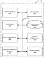
- FIG. 1shows an exemplary device 110 forming part of an environment within which aspects of the present disclosure may be implemented.
- the schematic diagramillustrates a user device 110 including several exemplary components. It will be appreciated that additional or alternative components may be used in a given implementation depending upon user preference, cost, and other considerations.
- the components of the user device 110include a display screen 120 , applications 130 , a processor 140 , a memory 150 , one or more input components 160 such as speech- and text-input facilities, and one or more output components 170 such as text- and audible-output facilities, e.g., one or more speakers.
- the one or more input components 160 of the device 110also include a sensor or system that measures or monitors a condition associated with wireless network connectivity or power drain.
- the conditionmay be, for example, power drain per unit time, power drain per unit data during transmission or receipt of data, and the like, sensed parameters such as device orientation relative to the earth, and relative to the user (e.g., pocket location or hand grip), and communication network parameters such as transmission frequency, band or channel grouping, bandwidth allocation, and modulation format.
- the device 110also includes a sensor configured for determining location of the device such as a GPS module and associated circuitry and software.
- the processor 140can be any of a microprocessor, microcomputer, application-specific integrated circuit, or the like.
- the processor 140can be implemented by one or more microprocessors or controllers from any desired family or manufacturer.
- the memory 150may reside on the same integrated circuit as the processor 140 . Additionally or alternatively, the memory 150 may be accessed via a network, e.g., via cloud-based storage.
- the memory 150may include a random-access memory. Additionally or alternatively, the memory 150 may include a read-only memory (i.e., a hard drive, flash memory, or any other desired type of memory device).
- the information that is stored by the memory 150can include program code associated with one or more operating systems or applications as well as informational data, e.g., program parameters, process data, etc.
- the operating system and applicationsare typically implemented via executable instructions stored in a non-transitory computer-readable medium (e.g., memory 150 ) to control basic functions of the electronic device 110 .
- Such functionsmay include, for example, interaction among various internal components and storage and retrieval of applications and data to and from the memory 150 .
- the illustrated device 110also includes a network interface module 180 to provide wireless communications to and from the device 110 .
- the network interface module 180may include multiple communications interfaces, e.g., for cellular, WiFi, broadband, and other communications.
- a power supply 190such as a battery, is included for providing power to the device 110 and its components.
- all or some of the internal componentscommunicate with one another by way of one or more shared or dedicated internal communication links 195 , such as an internal bus.
- applicationstypically utilize the operating system to provide more specific functionality, such as file-system service and handling of protected and unprotected data stored in the memory 150 .
- applicationsmay govern standard or required functionality of the user device 110
- applicationsgovern optional or specialized functionality, which can be provided, in some cases, by third-party vendors unrelated to the device manufacturer.
- informational datae.g., program parameters and process data
- this non-executable informationcan be referenced, manipulated, or written by the operating system or an application.
- informational datacan include, for example, data that are preprogrammed into the device during manufacture, data that are created by the device, or any of a variety of types of information that are uploaded to, downloaded from, or otherwise accessed at servers or other devices with which the device 110 is in communication during its ongoing operation.
- the device 110is programmed such that the processor 140 and memory 150 interact with the other components of the device 110 to perform a variety of functions.
- the processor 140may include or implement various modules and execute programs for initiating different activities such as launching an application, transferring data, and toggling through various graphical user-interface objects (e.g., toggling through various icons that are linked to executable applications).
- a mobile communication devicesuch as a mobile phone operating in accordance with an embodiment of the disclosed principles can operate with greater energy efficiency by using a power-drain map.
- the devicemay use the map to more efficiently select communication modes and optionally to predict future communication modes and modify device communication behavior accordingly.
- FIG. 2shows an example environment 200 within which an example device 201 is shown to be traveling and operating. As shown, the device 201 is currently (at time T 0 ) in a first position 202 , but is predicted to be in a different position 203 at a later time T 1 and in yet another position 204 at a still later time T 2 .
- the methodology used to predict the device's motionmay include any suitable prediction technique, including techniques based on known routes (e.g., learned user routes or known roads), device long-term history, device trajectory, user-calendar data, and so on.
- known routese.g., learned user routes or known roads
- device long-term historye.g., device trajectory, user-calendar data, and so on.
- the illustrated network environment 200includes network 205 , network 206 , and network 207 .
- the coverage areas of all three networks 205 , 206 , 207overlap.
- the coverage area of network 207is entirely contained within the coverage area of network 206 in the illustrated example.
- the device 201traverses the overall area, it is first within the coverage areas of networks 205 and 206 , moves into the coverage area of network 207 , and then moves out of all coverage areas except that of network 206 .
- FIG. 3a series of example power-drain map entries is shown in FIG. 3 corresponding to positions 202 , 203 and 204 for device 201 .
- this network 207provides an attractive option when it becomes available in the second entry.
- the coverage area for network 207does not extend far, and for most of its travel, the device 201 is outside of the coverage area of network 207 .
- the mobile device 201may choose to modify its behavior to most efficiently utilize its remaining power. For example, the device 201 (e.g., using a network selection and connection utilization application or routine run by the device processor) may decide to delay a power-intensive download at position 202 . Instead, the device may connect to network 207 once at position 203 and execute the needed download or downloads.
- the device 201e.g., using a network selection and connection utilization application or routine run by the device processor
- network 207is of a type that the device 201 supports but that is currently (at position 202 ) disabled on the device 201 .
- the mobile device 201may enable the network type associated with network 207 .
- the device 201may request that the user enable the network type associated with network 207 . However, if the device battery level is high, then the device 201 may opt for a less efficient immediate download in the interest of eliminating any delay in the user experience. Thus, the device battery level is also a consideration in determining what remedy to effectuate based on the map data. Other options, alternatives, and variations will become apparent.
- the coverage map datasuch as those shown in FIG. 3 may be retrieved from a coverage map server, e.g., a remote server, or from a local memory. Moreover, the coverage data may be communally created by numerous devices at various times or may be created by the single device in question over time.
- a deviceuses a power-drain map (whether earlier created by itself or retrieved from a map server), it can consult the map informed by its current battery level and communications needs and then apply an appropriate remedy. For example, it might be advisable based on the power-drain map to search for an alternative communication mode.
- the power-drain mapmay indicate that no alternative communication mode is viable at this location.
- the power-drain mapmay even guide the user of the device to a nearby location with better connectivity or to further communication mode options.
- the devicemay lead the device (or its user) to consider turning off data transmission or even all transmission (i.e., by going into airplane mode).
- the current connectivitymay be so good relative to upcoming locations that the device is advised to take advantage of the current connectivity by preemptively downloading as much data as possible before the device leaves the present area of good connectivity, similar to the delayed download discussed above.
- the device's predicted future locationis taken into account when generating current guidance for device communication and connectivity behavior.
- the device's predicted pathcan be compared against the coverage map to take preemptive action as needed. The preemptive download when in a location having good connectivity is an example of this.
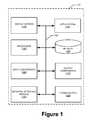
- the flowchart of FIG. 4illustrates a process 400 for utilizing a power-drain map to improve device efficiency and network behavior.
- the devicee.g., device 110 , 201 , retrieves a power-drain map from a map server over a network connection, e.g., a cellular or other network connection.
- a network connectione.g., a cellular or other network connection.
- the devicemay alternatively have created the map over time based on data it collected from the current location as well as other locations.
- the devicedetermines its geographical location at stage 402 .
- this stepis accomplished via GPS, although it will be appreciated that other methodologies such as WiFi localization may be used.
- the deviceaccesses the map data associated with its determined current position at stage 403 .
- the map datamay show condition data associated with the particular device and the determined position, e.g., an expected power drain associated with each available mode of communication.
- Modes of communicationmay include one or more cellular connections, one or more WiFi connections, or one or more other types of connections.
- Condition datamay also include present or predicted network condition data such as operating channel or band and modulation format.
- Condition datamay also include sensor data or conditions inferred from sensor data such as the device orientation with respect to the earth or the device position relative to the body of the user or a user grip.
- the devicedetermines its remaining battery power, also referred to as battery-charge level.
- the deviceBased on the map data and optionally on the current battery-charge level of the device, the device chooses and implements a course of action in stage 405 .
- a more extensive though not exhaustive listing of optionsincludes altering an interval of scanning for communications modes usable by the device, turning roaming off, disabling switching of communications modes by the device, switching to a different communications mode usable by the device, altering public land mobile network preference thresholds, turning off data reception, preemptively downloading data, and turning on airplane mode.
- optionsmay include informing the user of potentially advantageous changes in device orientation, position, or grip.
- the process 400is described as taking place at the device, it will be appreciated that the process 400 may be executed partially or entirely elsewhere.
- the map servermay execute some or all of the process 400 , with the understanding that the device may need to supply its location or data usable to determine its location.
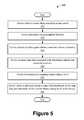
- FIG. 5A flowchart of an example process 500 in accordance with such an embodiment is shown in FIG. 5 .
- the deviceretrieves a power-drain map from a map server over a network connection, e.g., a cellular or other network connection.
- a network connectione.g., a cellular or other network connection.
- the devicemay alternatively create the map itself.
- the devicedetermines its geographical location at stage 502 , e.g., via GPS or other suitable methodology.
- the devicepredicts its future path within a certain frame of time or distance. For example, the prediction may be executed for a period of ten minutes or a distance of a quarter mile.
- the path predictionmay be based on any suitable factors, including, for example, current location of the device, current direction of movement of the device, a geographical map, observations of past behavior of the device, observations of past behavior of a user of the device, stored preferences, observations of a plurality of devices, observations of a plurality of users of devices, a time of day, and a current weather condition.
- the predictionmay actually be received from a device distinct from, and perhaps remote from, the wireless communications device itself.
- the deviceaccesses the map data associated with its determined current and predicted positions at stage 504 .
- the devicemay determine its remaining battery power at stage 505 .
- the devicechooses a path of action in stage 506 , choosing and implementing a remedy.
- options in the predictive caseinclude time-shifting options.
- the process 500is described as taking place at the device, it will be appreciated that the process 500 may be executed partially or entirely elsewhere.
- the map servermay execute some or all of the process 500 , with the understanding that the device may need to supply its location or data usable to determine its location.
- the power-drain mapmay be created by the device or the map server.
- the map serverreceives an association of a measured condition (wireless network connectivity or power drain for example) and a geographical location from a wireless communications device.
- the serverprogressively builds the power-drain map comprising the associated measured condition and location.
- the conditionmay relate to a communication mode usable by the wireless communications device.
- the conditionmay relate to the device orientation relative to the earth.
- the conditionmay also relate to the device orientation or position relative to a user.
- the mapincludes conditions and locations for each of a plurality of communication modes usable by wireless communications devices.
- the mapmay also include information associated with a model of the wireless communication device. For example, a power-drain model may be applied assuming a linear discharge of the device battery with increasing drain. Similarly, a more complex model may assume additional resistive losses with increased drain.
- the map serverincludes a communications interface configured to receive the association of a measured condition and a geographical location, as well as a processor configured to build the map comprising the associated measured condition and geographical location.
Landscapes
- Engineering & Computer Science (AREA)
- Computer Networks & Wireless Communication (AREA)
- Signal Processing (AREA)
- Data Mining & Analysis (AREA)
- Mobile Radio Communication Systems (AREA)
- Telephone Function (AREA)
Abstract
Description
This application is a continuation of and claims priority to U.S. patent application Ser. No. 14/457,190, filed on Aug. 12, 2014, which, in turn, claims priority under 35 U.S.C. § 119(e) to U.S. Provisional Patent Application 61/916,473, filed on Dec. 16, 2013, which is incorporated herein by reference in its entirety.
The present disclosure is related generally to mobile-device power usage and, more particularly, to a system and method for enhancing mobile-device power conservation through network selection.
Mobile wireless communication devices such as cellular and other wireless phones, tablets, watches, and so on are ubiquitous in large part because of their mobility. Certainly such devices have extensive capabilities, and these capabilities seem to be constantly increasing. However, a large stationary system will almost always have a greater computing capability than a small mobile device. Thus, the primary benefit of mobile devices remains their mobility.
In this connection, the usable mobility of such devices is directly related to the extent to which wireless communications are available. The availability of wireless communications is sometimes referred to as coverage. An absence of coverage can cause dropped calls, failures to load media or applications, missed messages, and so on. However, not only does coverage affect connectivity, it also directly impacts the power cost of communications. For example, in an area of poor coverage due to a distant base station, the power cost of transmitting over the required distance may be much greater than the power cost would be if the base station were closer.
The present disclosure is directed to a system that may conserve device battery resources by strategic coverage tracking and network selection. However, it should be appreciated that any such benefit is not necessarily a limitation on the scope of the disclosed principles or of the attached claims, except to the extent expressly noted in the claims. Additionally, the discussion of technology in this Background section is merely reflective of inventor observations or considerations and is not intended to be admitted or assumed prior art as to the discussed details. Moreover, the identification of the desirability of a certain course of action is the inventors' observation, not an art-recognized desirability.
While the appended claims set forth the features of the present techniques with particularity, these techniques, together with their objects and advantages, may be best understood from the following detailed description taken in conjunction with the accompanying drawings of which:
Before presenting a detailed discussion of embodiments of the disclosed principles, an overview of certain embodiments is given to aid the reader in approaching the later discussion. As noted above, the quality of wireless connectivity available to a mobile device can affect the power required of the device to engage in wireless communications. To accommodate varying coverage conditions, a wireless device may investigate to determine whether a wireless communication mode different from the one currently being used by the device offers better coverage. If so, the device may switch and start using this alternative communication mode.
The alternative mode may represent an entirely different communication technology. For example, a local WiFi network may provide better connectivity than a cellular network that a mobile device is currently using. Alternatively, the alternative mode may include a different provider of the same technology. For example, a new cellular provider may provide better coverage at the current location than the current cellular provider.
However, searching for better communications modes and frequently switching among communications modes are both energy-intensive processes that consume substantial amounts of battery power on the device. To minimize this power drain, a coverage map may be used to eliminate the need to investigate alternative modes in real time. By noting its own geographical location (e.g., by means of a Global Positioning System (“GPS”)) and then referencing an appropriate coverage map, a device is able to select a best communication mode for its present location. The device can then switch to that mode without expending the power to search for alternative modes.
Alternatively, the coverage map can reveal that the mode currently used by the device, though of less than optimal quality, is no worse than the alternatives. This again saves the device from expending the power that would have been needed to independently investigate other available modes in real time, and the device does not switch modes.
In an embodiment of the disclosed principles, coverage maps are generated and provided that take into direct consideration the power needs of different types of devices with different capabilities in different stages of power use. For example, a device that is low on power can consult such a map to determine, given its current battery level, its communications needs, and its current geographic location, what communication mode it should be using. Herein, this type of coverage map is sometimes referred to as a “power-drain map.”
In an embodiment, wireless devices collect information to create the coverage map and share collected information with a map server. The coverage map includes information specific to a type of communication device and to each communication mode usable by that type of device in a further embodiment. If a particular communication mode is usable by a device but has been disabled, then the coverage map, as presented to this device, can be altered to remove references to the disabled mode. Alternatively, the user is alerted that this currently disabled mode is preferable to other enabled modes, such that the user may consider enabling this mode.
When a device uses the power-drain map (whether earlier created by itself or retrieved from a map server), it can consult the map informed by its current battery level and communications needs and then apply an appropriate remedy. For example, it might be advisable based on the power-drain map to search for an alternative communication mode. Alternatively, the power-drain map may indicate that no alternative communication mode is viable at this location. The power-drain map may even guide the user of the device to a nearby location with better connectivity or further communication-mode options.
In extreme cases, consulting with the map may lead the device (or its user) to consider turning off data transmission or even all transmission (i.e., by going into airplane mode). On the other hand, the current connectivity may be so good relative to upcoming locations that the device is advised to take advantage of the current connectivity by preemptively downloading as much data as possible before the device leaves the present area of good connectivity.
Regarding the comparison of upcoming locations to the device's current locations, in an embodiment, the device's predicted future location is taken into account when generating current guidance for device communication and connectivity behavior. In one aspect of this behavior, the device's predicted path can be compared against the coverage map to take preemptive action as needed. The preemptive download when in a location having good connectivity is an example of this.
Having considered a high level overview of the disclosed principles and turning now to a more detailed discussion in conjunction with the attached figures, techniques of the present disclosure are illustrated as being implemented in a suitable environment. The following description is based on embodiments of the disclosed principles and should not be taken as limiting the claims with regard to alternative embodiments that are not explicitly described herein. Thus, for example, whileFIG. 1 illustrates an example mobile device within which embodiments of the disclosed principles may be implemented, it will be appreciated that many other devices such as but not limited to laptop computers, tablet computers, personal computers, embedded automobile computing systems and so on may also be used.
The schematic diagram ofFIG. 1 shows anexemplary device 110 forming part of an environment within which aspects of the present disclosure may be implemented. In particular, the schematic diagram illustrates auser device 110 including several exemplary components. It will be appreciated that additional or alternative components may be used in a given implementation depending upon user preference, cost, and other considerations.
In the illustrated embodiment, the components of theuser device 110 include adisplay screen 120,applications 130, aprocessor 140, amemory 150, one ormore input components 160 such as speech- and text-input facilities, and one ormore output components 170 such as text- and audible-output facilities, e.g., one or more speakers.
The one ormore input components 160 of thedevice 110 also include a sensor or system that measures or monitors a condition associated with wireless network connectivity or power drain. The condition may be, for example, power drain per unit time, power drain per unit data during transmission or receipt of data, and the like, sensed parameters such as device orientation relative to the earth, and relative to the user (e.g., pocket location or hand grip), and communication network parameters such as transmission frequency, band or channel grouping, bandwidth allocation, and modulation format. Similarly, thedevice 110 also includes a sensor configured for determining location of the device such as a GPS module and associated circuitry and software.
Theprocessor 140 can be any of a microprocessor, microcomputer, application-specific integrated circuit, or the like. For example, theprocessor 140 can be implemented by one or more microprocessors or controllers from any desired family or manufacturer. Similarly, thememory 150 may reside on the same integrated circuit as theprocessor 140. Additionally or alternatively, thememory 150 may be accessed via a network, e.g., via cloud-based storage. Thememory 150 may include a random-access memory. Additionally or alternatively, thememory 150 may include a read-only memory (i.e., a hard drive, flash memory, or any other desired type of memory device).
The information that is stored by thememory 150 can include program code associated with one or more operating systems or applications as well as informational data, e.g., program parameters, process data, etc. The operating system and applications are typically implemented via executable instructions stored in a non-transitory computer-readable medium (e.g., memory150) to control basic functions of theelectronic device 110. Such functions may include, for example, interaction among various internal components and storage and retrieval of applications and data to and from thememory 150.
The illustrateddevice 110 also includes anetwork interface module 180 to provide wireless communications to and from thedevice 110. Thenetwork interface module 180 may include multiple communications interfaces, e.g., for cellular, WiFi, broadband, and other communications. Apower supply 190, such as a battery, is included for providing power to thedevice 110 and its components. In an embodiment, all or some of the internal components communicate with one another by way of one or more shared or dedicatedinternal communication links 195, such as an internal bus.
Further with respect to the applications, these typically utilize the operating system to provide more specific functionality, such as file-system service and handling of protected and unprotected data stored in thememory 150. Although many applications may govern standard or required functionality of theuser device 110, in many cases applications govern optional or specialized functionality, which can be provided, in some cases, by third-party vendors unrelated to the device manufacturer.
Finally, with respect to informational data, e.g., program parameters and process data, this non-executable information can be referenced, manipulated, or written by the operating system or an application. Such informational data can include, for example, data that are preprogrammed into the device during manufacture, data that are created by the device, or any of a variety of types of information that are uploaded to, downloaded from, or otherwise accessed at servers or other devices with which thedevice 110 is in communication during its ongoing operation.
In an embodiment, thedevice 110 is programmed such that theprocessor 140 andmemory 150 interact with the other components of thedevice 110 to perform a variety of functions. Theprocessor 140 may include or implement various modules and execute programs for initiating different activities such as launching an application, transferring data, and toggling through various graphical user-interface objects (e.g., toggling through various icons that are linked to executable applications).
As noted above in overview, a mobile communication device such as a mobile phone operating in accordance with an embodiment of the disclosed principles can operate with greater energy efficiency by using a power-drain map. In particular, the device may use the map to more efficiently select communication modes and optionally to predict future communication modes and modify device communication behavior accordingly.
Before describing the process flows involved in these techniques, an example network environment is described for common reference later. In particular, the simplified network diagram ofFIG. 2 shows anexample environment 200 within which anexample device 201 is shown to be traveling and operating. As shown, thedevice 201 is currently (at time T0) in afirst position 202, but is predicted to be in adifferent position 203 at a later time T1and in yet anotherposition 204 at a still later time T2.
The methodology used to predict the device's motion may include any suitable prediction technique, including techniques based on known routes (e.g., learned user routes or known roads), device long-term history, device trajectory, user-calendar data, and so on.
The illustratednetwork environment 200 includesnetwork 205,network 206, andnetwork 207. In the example, the coverage areas of all threenetworks network 207 is entirely contained within the coverage area ofnetwork 206 in the illustrated example. As thedevice 201 traverses the overall area, it is first within the coverage areas ofnetworks network 207, and then moves out of all coverage areas except that ofnetwork 206.
Given this progression, a series of example power-drain map entries is shown inFIG. 3 corresponding topositions device 201. As can be seen, although coverage fornetwork 207 is not initially available, thisnetwork 207 provides an attractive option when it becomes available in the second entry. The coverage area fornetwork 207 does not extend far, and for most of its travel, thedevice 201 is outside of the coverage area ofnetwork 207.
Having predicted the illustrated path and retrieved at least the illustrated power-drain map entries, themobile device 201 may choose to modify its behavior to most efficiently utilize its remaining power. For example, the device201 (e.g., using a network selection and connection utilization application or routine run by the device processor) may decide to delay a power-intensive download atposition 202. Instead, the device may connect to network207 once atposition 203 and execute the needed download or downloads.
In an embodiment,network 207 is of a type that thedevice 201 supports but that is currently (at position202) disabled on thedevice 201. Upon predicting the illustrated path, retrieving the illustrated power-drain map entries, and determining that a download inposition 203 will be more power efficient than a download atposition 202, themobile device 201 may enable the network type associated withnetwork 207.
Alternatively, thedevice 201 may request that the user enable the network type associated withnetwork 207. However, if the device battery level is high, then thedevice 201 may opt for a less efficient immediate download in the interest of eliminating any delay in the user experience. Thus, the device battery level is also a consideration in determining what remedy to effectuate based on the map data. Other options, alternatives, and variations will become apparent.
In yet another alternative embodiment, if a particular communication mode is usable by a device but has been disabled, then the coverage map, as presented to this device, is altered to remove data for the disabled mode.
The coverage map data such as those shown inFIG. 3 may be retrieved from a coverage map server, e.g., a remote server, or from a local memory. Moreover, the coverage data may be communally created by numerous devices at various times or may be created by the single device in question over time.
When a device uses a power-drain map (whether earlier created by itself or retrieved from a map server), it can consult the map informed by its current battery level and communications needs and then apply an appropriate remedy. For example, it might be advisable based on the power-drain map to search for an alternative communication mode. Alternatively, the power-drain map may indicate that no alternative communication mode is viable at this location. The power-drain map may even guide the user of the device to a nearby location with better connectivity or to further communication mode options.
In extreme cases, consulting with the map may lead the device (or its user) to consider turning off data transmission or even all transmission (i.e., by going into airplane mode). On the other hand, the current connectivity may be so good relative to upcoming locations that the device is advised to take advantage of the current connectivity by preemptively downloading as much data as possible before the device leaves the present area of good connectivity, similar to the delayed download discussed above.
Regarding the comparison of upcoming locations to the device's current locations, in an embodiment, the device's predicted future location is taken into account when generating current guidance for device communication and connectivity behavior. In one aspect of this behavior, the device's predicted path can be compared against the coverage map to take preemptive action as needed. The preemptive download when in a location having good connectivity is an example of this.
The flowchart ofFIG. 4 illustrates aprocess 400 for utilizing a power-drain map to improve device efficiency and network behavior. Atstage 401 of theprocess 400, the device, e.g.,device
The device determines its geographical location atstage 402. In an embodiment, this step is accomplished via GPS, although it will be appreciated that other methodologies such as WiFi localization may be used.
The device accesses the map data associated with its determined current position atstage 403. In keeping with the foregoing discussion, the map data may show condition data associated with the particular device and the determined position, e.g., an expected power drain associated with each available mode of communication. Modes of communication may include one or more cellular connections, one or more WiFi connections, or one or more other types of connections. Condition data may also include present or predicted network condition data such as operating channel or band and modulation format. Condition data may also include sensor data or conditions inferred from sensor data such as the device orientation with respect to the earth or the device position relative to the body of the user or a user grip. Atstage 404, the device determines its remaining battery power, also referred to as battery-charge level.
Based on the map data and optionally on the current battery-charge level of the device, the device chooses and implements a course of action instage 405. Although certain types of actions were discussed above, a more extensive though not exhaustive listing of options includes altering an interval of scanning for communications modes usable by the device, turning roaming off, disabling switching of communications modes by the device, switching to a different communications mode usable by the device, altering public land mobile network preference thresholds, turning off data reception, preemptively downloading data, and turning on airplane mode. Furthermore, options may include informing the user of potentially advantageous changes in device orientation, position, or grip.
Although theprocess 400 is described as taking place at the device, it will be appreciated that theprocess 400 may be executed partially or entirely elsewhere. For example, the map server may execute some or all of theprocess 400, with the understanding that the device may need to supply its location or data usable to determine its location.
As noted above, device-path prediction is used as an additional factor in an embodiment of the disclosed principles to determine a course of action for the device. A flowchart of anexample process 500 in accordance with such an embodiment is shown inFIG. 5 . Atstage 501 of theprocess 500, the device retrieves a power-drain map from a map server over a network connection, e.g., a cellular or other network connection. As noted above, the device may alternatively create the map itself.
The device determines its geographical location atstage 502, e.g., via GPS or other suitable methodology. Atstage 503, the device predicts its future path within a certain frame of time or distance. For example, the prediction may be executed for a period of ten minutes or a distance of a quarter mile.
The path prediction may be based on any suitable factors, including, for example, current location of the device, current direction of movement of the device, a geographical map, observations of past behavior of the device, observations of past behavior of a user of the device, stored preferences, observations of a plurality of devices, observations of a plurality of users of devices, a time of day, and a current weather condition. Moreover, the prediction may actually be received from a device distinct from, and perhaps remote from, the wireless communications device itself.
The device accesses the map data associated with its determined current and predicted positions atstage 504. As with the prior embodiment, the device may determine its remaining battery power atstage 505. Based on the map data and optionally the current battery-charge level of the device, the device chooses a path of action instage 506, choosing and implementing a remedy. Unlike the non-predictive case, options in the predictive case include time-shifting options.
Although theprocess 500 is described as taking place at the device, it will be appreciated that theprocess 500 may be executed partially or entirely elsewhere. For example, the map server may execute some or all of theprocess 500, with the understanding that the device may need to supply its location or data usable to determine its location.
As noted above, the power-drain map may be created by the device or the map server. In the latter case, the map server receives an association of a measured condition (wireless network connectivity or power drain for example) and a geographical location from a wireless communications device. The server progressively builds the power-drain map comprising the associated measured condition and location. The condition may relate to a communication mode usable by the wireless communications device. The condition may relate to the device orientation relative to the earth. The condition may also relate to the device orientation or position relative to a user.
In an embodiment, the map includes conditions and locations for each of a plurality of communication modes usable by wireless communications devices. The map may also include information associated with a model of the wireless communication device. For example, a power-drain model may be applied assuming a linear discharge of the device battery with increasing drain. Similarly, a more complex model may assume additional resistive losses with increased drain.
Although the map server architecture is not critical, in an embodiment, the map server includes a communications interface configured to receive the association of a measured condition and a geographical location, as well as a processor configured to build the map comprising the associated measured condition and geographical location.
In view of the many possible embodiments to which the principles of the present disclosure may be applied, it should be recognized that the embodiments described herein with respect to the drawing figures are meant to be illustrative only and should not be taken as limiting the scope of the claims. Therefore, the techniques as described herein contemplate all such embodiments as may come within the scope of the following claims and equivalents thereof.
Claims (20)
1. A wireless communication device comprising:
a location sensor;
a power drain sensor;
a battery;
a processor; and
a memory comprising instructions that configure the wireless communication device to build a power-drain map, the instructions executable by the processor to configure the wireless communication device to:
determine a current geographical location using the location sensor;
measure, using the power drain sensor, a power drain associated with wireless connectivity at the current geographical location related to a current communication mode in use by the wireless communication device;
associate the measured power drain with the current geographical location and the current communication mode; and
build the power-drain map comprising the measured power drain, the current communication mode, current geographical location, and information associated with a power-drain model for increasing drain of the battery, the power-drain map being usable by the wireless communication device to modify a communication behavior to reduce consumption of remaining battery power.
2. The wireless communication device ofclaim 1 , wherein the power-drain map comprises associated measured power drains and geographical locations for each of a plurality of communication modes usable by the wireless communication device.
3. The wireless communication device ofclaim 1 , wherein the power-drain map omits the power drains and the geographical locations for a communication mode that is disabled.
4. The wireless communication device ofclaim 1 , wherein the measurement of the power drain includes the measurement of one or more of a power drain per unit time, a power drain per unit data during transmission, or a power drain per unit data during reception.
5. The wireless communication device ofclaim 1 , wherein the location sensor is a Global Positioning System module.
6. The wireless communication device ofclaim 1 , further comprising a Wi-Fi communication interface, and wherein the determination of the current geographical location employs Wi-Fi localization to identify the current geographical location.
7. The wireless communication device ofclaim 1 , further comprising an orientation sensor, and the instructions executable to configure the wireless communication device to measure one or more of a device orientation relative to the earth, or a device orientation relative to a user.
8. A system for modifying a communication behavior of a wireless communication device, the system comprising:
a location module;
a processor; and
a memory comprising instructions for modifying the communication behavior of the wireless communication device, the instructions executable by the processor to configure the system to:
determine, using the location module, a current geographical location and at least one predicted future geographical location of the wireless communication device;
determine, based on a power-drain map, the power-drain map including information associated with a power-drain model for increasing drain of a battery of the wireless communication device, a power-drain condition associated with one or more available communication modes at each of the current geographical location, and the at least one predicted future geographical location; and
based at least in part on the determined power drains associated with the one or more available communication modes at each of the current geographical location and the at least one predicted future geographical location, modify the communication behavior of the wireless communication device to reduce consumption of remaining battery power of the wireless communication device using the model for the increasing drain of the battery.
9. The system ofclaim 8 , the instructions executable by the processor to further configure the system to create the power-drain map.
10. The system ofclaim 8 , wherein the power-drain map is received from a map server.
11. The system ofclaim 8 , wherein the modification of the communication behavior includes: altering an interval of scanning for communication modes available to the wireless communication device, turning roaming off, disabling switching of communications modes, switching to a different communication mode, altering public land mobile network preference thresholds, turning off data reception, preemptively downloading data, delaying a data communication, turning on airplane mode, and advising a user to change at least one of device orientation, position, and grip.
12. The system ofclaim 8 , wherein the modification of the communication behavior is based, at least in part, on a current battery-charge level of the wireless communication device.
13. The system ofclaim 8 , wherein the determination of the at least one predicted future geographical location of the wireless communication device is based, at least in part, on one or more of: a current location of the wireless communication device, a current direction of movement of the wireless communication device, a geographical map, observations of past behavior of the wireless communication device, observations of past behavior of a user of the wireless communication device, stored preferences, observations of a plurality of wireless communication devices, observations of a plurality of users of wireless communication devices, a time of day, or a current weather condition.
14. The system ofclaim 8 , wherein the determination of the at least one predicted future geographical location of the wireless communication device is performed on a device remote from the wireless communication device.
15. The system ofclaim 8 , wherein the power-drain model for increasing drain of the battery of the wireless communication device assumes a linear discharge of the battery with increasing drain.
16. The system ofclaim 8 , wherein the power-drain model for increasing drain of the battery of the wireless communication device assumes increasing resistive losses with increasing drain.
17. A map server comprising:
a processor; and
memory comprising instructions that configure the map server to modify a communication behavior of a wireless communication device, the instructions executable to configure the map server to:
receive a report of a current geographical location of the wireless communication device;
predict a future location of the wireless communication device;
read a power-drain map to obtain power-drain data associated with the current geographical location and the future location of the wireless communication device, the power-drain data for each location reflecting a wireless connectivity power cost for each of one or more communication modes available at that location and including information associated with a power-drain model for increasing drain of a battery of the wireless communication device; and
based at least in part on the obtained power-drain data, select a course of action regarding behavior of the wireless communication device with respect to wireless communication, the course of action including modifying the communication behavior of the wireless communication device, using the model for the increasing drain of the battery, to reduce consumption of remaining battery power of the wireless communication device.
18. The map server ofclaim 17 , wherein the course of action regarding behavior of the wireless communication device with respect to wireless communication includes: preemptively downloading data to the wireless communication device, instructing the wireless communication device to advise a user to change at least one of device orientation, position, and grip, or suggest to the wireless communication device one of: altering its interval of scanning for usable communication modes, turning roaming off or on, disabling switching of communications modes, switching to a different communication mode, altering its public land mobile network preference thresholds, turning off data reception, or turning on airplane mode.
19. The map server ofclaim 17 , wherein the selection of the course of action regarding behavior of the wireless communication device with respect to wireless communication is based, at least in part, on a current battery-charge level reported by the wireless communication device.
20. The map server ofclaim 17 , wherein predicting the future location of the wireless communication device uses one or more of: a current location of the wireless communication device, a current direction of movement of the wireless communication device, a geographical map, observations of past behavior of the wireless communication device, observations of past behavior of a user of the wireless communication device, stored preferences, observations of a plurality of wireless communication devices, observations of a plurality of users of wireless communication devices, a time of day, or a current weather condition.
Priority Applications (1)
| Application Number | Priority Date | Filing Date | Title |
|---|---|---|---|
| US15/454,579US9949210B2 (en) | 2013-12-16 | 2017-03-09 | Remedying power drain via a coverage map |
Applications Claiming Priority (3)
| Application Number | Priority Date | Filing Date | Title |
|---|---|---|---|
| US201361916473P | 2013-12-16 | 2013-12-16 | |
| US14/457,190US9596653B2 (en) | 2013-12-16 | 2014-08-12 | Remedying power drain via a coverage map |
| US15/454,579US9949210B2 (en) | 2013-12-16 | 2017-03-09 | Remedying power drain via a coverage map |
Related Parent Applications (1)
| Application Number | Title | Priority Date | Filing Date |
|---|---|---|---|
| US14/457,190ContinuationUS9596653B2 (en) | 2013-12-16 | 2014-08-12 | Remedying power drain via a coverage map |
Publications (2)
| Publication Number | Publication Date |
|---|---|
| US20170188309A1 US20170188309A1 (en) | 2017-06-29 |
| US9949210B2true US9949210B2 (en) | 2018-04-17 |
Family
ID=53370187
Family Applications (2)
| Application Number | Title | Priority Date | Filing Date |
|---|---|---|---|
| US14/457,190ActiveUS9596653B2 (en) | 2013-12-16 | 2014-08-12 | Remedying power drain via a coverage map |
| US15/454,579ActiveUS9949210B2 (en) | 2013-12-16 | 2017-03-09 | Remedying power drain via a coverage map |
Family Applications Before (1)
| Application Number | Title | Priority Date | Filing Date |
|---|---|---|---|
| US14/457,190ActiveUS9596653B2 (en) | 2013-12-16 | 2014-08-12 | Remedying power drain via a coverage map |
Country Status (2)
| Country | Link |
|---|---|
| US (2) | US9596653B2 (en) |
| WO (1) | WO2015095072A1 (en) |
Cited By (1)
| Publication number | Priority date | Publication date | Assignee | Title |
|---|---|---|---|---|
| US11191034B2 (en)* | 2019-08-13 | 2021-11-30 | Samsung Electronics Co., Ltd. | Electronic device for backing off transmission power based on SAR and operation method thereof |
Families Citing this family (12)
| Publication number | Priority date | Publication date | Assignee | Title |
|---|---|---|---|---|
| US9596653B2 (en) | 2013-12-16 | 2017-03-14 | Google Technology Holdings LLC | Remedying power drain via a coverage map |
| US9865897B2 (en) | 2014-06-02 | 2018-01-09 | Google Llc | Stacked electrochemical cell with increased energy density |
| US9472965B2 (en) | 2014-09-08 | 2016-10-18 | Google Technology Holdings LLC | Battery cycle life through smart overnight charging |
| US9913230B1 (en) | 2017-04-11 | 2018-03-06 | Motorola Mobility Llc | Reduced power device discovery and corresponding devices and methods |
| CN109195203A (en)* | 2018-10-22 | 2019-01-11 | Oppo广东移动通信有限公司 | parameter configuration method, device, terminal and storage medium of wireless local area network |
| US10506650B1 (en) | 2018-11-19 | 2019-12-10 | Motorola Mobility Llc | Methods and systems for pairing electronic devices based upon proximity |
| US10849034B1 (en) | 2019-11-26 | 2020-11-24 | Motorola Mobility Llc | Signal map for wireless connectivity |
| US11129032B2 (en) | 2019-11-26 | 2021-09-21 | Motorola Mobility Llc | Optimal device position for wireless communication |
| WO2022071639A1 (en) | 2020-10-02 | 2022-04-07 | 삼성전자 주식회사 | Network switching device and operating method of network switching device |
| CN114828172A (en)* | 2021-01-29 | 2022-07-29 | 深圳市万普拉斯科技有限公司 | Method and device for reducing standby power consumption, communication terminal and readable storage medium |
| US12021716B2 (en)* | 2021-09-03 | 2024-06-25 | Dish Wireless L.L.C. | Systems and methods for implementing digital twin with a live streaming map |
| US12267912B2 (en) | 2021-12-21 | 2025-04-01 | Dish Wireless L.L.C. | Systems and methods for providing applications with access to network functionality |
Citations (167)
| Publication number | Priority date | Publication date | Assignee | Title |
|---|---|---|---|---|
| US2499663A (en) | 1949-06-08 | 1950-03-07 | Sterlingworth Company | Safety device for thermally controlled battery chargers |
| US2529038A (en) | 1949-04-14 | 1950-11-07 | Sterlingworth Company | Maximum temperature cutoff system for battery chargers |
| US2563234A (en) | 1949-10-14 | 1951-08-07 | Sterlingworth Company | Safety thermal control system for battery chargers |
| US2627060A (en) | 1947-12-23 | 1953-01-27 | Charles B Berg | Controlling means for battery chargers |
| US2637836A (en) | 1950-11-24 | 1953-05-05 | Gen Motors Corp | Method for charging storage batteries |
| US3678363A (en) | 1970-04-06 | 1972-07-18 | Globe Union Inc | Automatic battery charger with multiple rate charging |
| US4061956A (en) | 1975-11-06 | 1977-12-06 | Utah Research And Development Company | Electronic DC battery charger |
| US4082097A (en) | 1976-05-20 | 1978-04-04 | Pacesetter Systems Inc. | Multimode recharging system for living tissue stimulators |
| US4629965A (en) | 1985-02-26 | 1986-12-16 | General Battery Corporation | Battery charger termination circuit |
| US4649333A (en) | 1985-04-30 | 1987-03-10 | Levitt-Safety Limited | Two terminal nicad battery charger with battery voltage and temperature sensing |
| US4692682A (en) | 1985-12-23 | 1987-09-08 | Levitt Safety Limited | Nicad battery charger |
| US4712055A (en) | 1987-04-01 | 1987-12-08 | The Singer Company | Battery charger circuit |
| US4727306A (en) | 1986-06-26 | 1988-02-23 | Motorola, Inc. | Portable battery charger |
| US4745349A (en) | 1986-10-16 | 1988-05-17 | Allied Corporation | Apparatus and method for charging and testing batteries |
| US5012176A (en) | 1990-04-03 | 1991-04-30 | Baxter International, Inc. | Apparatus and method for calorimetrically determining battery charge state |
| US5136231A (en) | 1990-10-12 | 1992-08-04 | Compaq Computer Corporation | Ni-cad battery charge rate controller |
| US5166596A (en) | 1991-08-29 | 1992-11-24 | Motorola, Inc. | Battery charger having variable-magnitude charging current source |
| US5172044A (en) | 1990-02-27 | 1992-12-15 | Sony Corporation | Multi-rate constant voltage battery charger with display |
| US5179335A (en) | 1987-10-09 | 1993-01-12 | Norvik Inc. | Battery charger |
| US5185566A (en) | 1990-05-04 | 1993-02-09 | Motorola, Inc. | Method and apparatus for detecting the state of charge of a battery |
| WO1993006682A1 (en) | 1991-09-16 | 1993-04-01 | Motorola, Inc. | Battery saver for wireless telephone |
| US5363031A (en) | 1989-12-05 | 1994-11-08 | Norand Corporation | Fast battery charger |
| US5481175A (en) | 1993-12-20 | 1996-01-02 | Motorola, Inc. | System and method for charging auxiliary batteries |
| US5504416A (en) | 1993-12-15 | 1996-04-02 | Unitrode Corporation | Battery charger circuit including battery temperature control |
| US5523667A (en) | 1992-01-27 | 1996-06-04 | Feldstein; Robert S. | Alkaline battery charger and method of operating same |
| US5600230A (en) | 1994-12-15 | 1997-02-04 | Intel Corporation | Smart battery providing programmable remaining capacity and run-time alarms based on battery-specific characteristics |
| US5640059A (en) | 1995-12-21 | 1997-06-17 | Reltec Corporation | Power supply system including thermal current limiting protection |
| US5656920A (en) | 1992-10-13 | 1997-08-12 | Gnb Battery Technologies, Inc. | Method and apparatus for charging a lead-acid battery |
| JPH09247852A (en) | 1996-03-08 | 1997-09-19 | Sony Corp | Battery pack and controlling method of battery |
| US5731694A (en) | 1993-03-23 | 1998-03-24 | Linear Technology Corporation | Control circuit and method for maintaining high efficiency over broard current ranges in a switching regulator circuit |
| US5736834A (en) | 1995-12-12 | 1998-04-07 | Toyota Jidosha Kabushiki Kaisha | Battery charger and method for completing charging at designated time |
| US5804944A (en) | 1997-04-07 | 1998-09-08 | Motorola, Inc. | Battery protection system and process for charging a battery |
| US5815389A (en) | 1996-10-03 | 1998-09-29 | Reltec Corporation | System level current limiting |
| US5900718A (en) | 1996-08-16 | 1999-05-04 | Total Battery Management, | Battery charger and method of charging batteries |
| US6094033A (en) | 1998-10-02 | 2000-07-25 | Georgia Tech Research Corporation | Battery state of charge detector with rapid charging capability and method |
| US6144186A (en) | 1999-07-16 | 2000-11-07 | Motorola, Inc. | Low power enable circuit |
| US6236189B1 (en) | 1999-02-11 | 2001-05-22 | Braun Gmbh | Method for determining a charge status of a battery |
| US6275006B1 (en) | 1998-05-27 | 2001-08-14 | Matsushita Electric Industrial Co., Ltd. | Method for charging secondary battery |
| US20010017602A1 (en) | 2000-01-07 | 2001-08-30 | Mario Hieb | Digital exciter/phasor/transmitter for directional antenna system |
| US6298233B1 (en) | 1999-08-13 | 2001-10-02 | Motorola, Inc. | Method and apparatus in a two-way wireless communication system for detection and deferred reporting of a communication difficulty |
| US6330455B1 (en) | 1998-07-27 | 2001-12-11 | Nec Corporation | Transmission power controller for use in mobile communication terminal equipment |
| US6470003B1 (en) | 1999-12-07 | 2002-10-22 | Motorola, Inc. | Method and apparatus in a two-way radio messaging unit for limiting a total transmission duration within a sliding time window |
| DE10118189A1 (en) | 2001-04-11 | 2002-11-07 | Siemens Ag | Test circuit to check state of switch in battery powered equipment operating in standby mode has voltage supply connected to parallel circuit that connects with control unit and switching stage |
| US6495992B1 (en) | 1996-03-26 | 2002-12-17 | Norvik Traction Inc. | Method and apparatus for charging batteries utilizing heterogeneous reaction kinetics |
| EP1298809A2 (en) | 2001-09-28 | 2003-04-02 | Siemens Information and Communication Mobile LLC | System and method for reducing SAR values |
| US20030085684A1 (en) | 2001-11-07 | 2003-05-08 | Quallion Llc | Implantable medical power module |
| US20030189417A1 (en) | 1992-10-07 | 2003-10-09 | Dallas Semiconductor Corporation | Method of controlling the charging of a battery |
| US6639462B1 (en) | 2002-06-27 | 2003-10-28 | Harris Corporation | Digital AM transmitter having tracking power supply compensation |
| JP2003333200A (en) | 2002-05-13 | 2003-11-21 | Yazaki Corp | Prepaid gas remaining amount management system and gas meter |
| US20030228875A1 (en) | 2002-06-05 | 2003-12-11 | Alapuranen Pertti O. | MAC protocol with duty-cycle limitation for portable devices in a wireless Ad-Hoc communication network and a method for using the same |
| US20030228891A1 (en) | 2002-06-05 | 2003-12-11 | Nec Corporation | Mobile phone, analysis device included therein, and analysis method |
| US20040075494A1 (en) | 2002-10-17 | 2004-04-22 | Armin Klomsdorf | Power amplification circuit and method for supplying power at a plurality of desired power output levels |
| US20040117330A1 (en) | 2002-03-28 | 2004-06-17 | Ehlers Gregory A. | System and method for controlling usage of a commodity |
| US6771051B2 (en) | 2002-06-29 | 2004-08-03 | Motorola, Inc. | Thermally limited battery protection and charging circuit |
| US20040176125A1 (en) | 2003-03-05 | 2004-09-09 | Samsung Electronics Co., Ltd. | Method and apparatus for controlling specific absorption rate in a mobile communication terminal |
| US6803746B2 (en) | 2001-11-02 | 2004-10-12 | Aker Wade Power Technologies, Llc | Fast charger for high capacity batteries |
| US20040222769A1 (en) | 2001-05-14 | 2004-11-11 | Adnan Al-Anbuky | Stress management of battery recharge and method of state charge estimation |
| US20040257040A1 (en) | 2003-06-19 | 2004-12-23 | Xiong Seng P. | Charge boost battery charging and protection circuit |
| US20050017677A1 (en) | 2003-07-24 | 2005-01-27 | Burton Andrew F. | Method and system for providing induction charging having improved efficiency |
| US20050030094A1 (en) | 2003-08-05 | 2005-02-10 | Motorola, Inc. | Low power consumption adaptive power amplifier |
| US20050046387A1 (en) | 2001-11-02 | 2005-03-03 | Aker John F. | Fast charger for high capacity batteries |
| US20050168193A1 (en) | 2003-05-03 | 2005-08-04 | Xiong Seng P. | Charging circuit with two levels of safety |
| US6927555B2 (en) | 2002-06-13 | 2005-08-09 | Motorola, Inc. | Sleep mode batteries in electronics devices and methods therefor |
| US20050253561A1 (en) | 2004-05-11 | 2005-11-17 | Tibbs Bobby L | Temperature sensitive charging of batteries with simple chargers |
| US20060028176A1 (en) | 2004-07-22 | 2006-02-09 | Qingfeng Tang | Cellular telephone battery recharging apparatus |
| US20060158156A1 (en) | 2005-01-17 | 2006-07-20 | Paul Gamboa | Method and apparatus for charging and discharging a rechargeable battery |
| US20060269835A1 (en) | 2005-05-18 | 2006-11-30 | Samsung Sdi Co., Ltd. | Jelly-roll type electrode assembly and lithium secondary battery with the same |
| US7151411B2 (en) | 2004-03-17 | 2006-12-19 | Paratek Microwave, Inc. | Amplifier system and method |
| US7158804B2 (en) | 2002-11-27 | 2007-01-02 | Lucent Technologies Inc. | Uplink scheduling for wireless networks |
| US20070069735A1 (en) | 2004-07-13 | 2007-03-29 | Siemen Aktiengesellschaft | Battery sensor and method for the operation of a battery sensor |
| US20070188139A1 (en) | 2006-02-16 | 2007-08-16 | Summit Microelectronics, Inc | System and method of charging a battery using a switching regulator |
| US20080074084A1 (en) | 2006-09-26 | 2008-03-27 | Motorola, Inc. | Electronic device and method for controlling charging current |
| US20080154624A1 (en) | 2006-06-29 | 2008-06-26 | Carina Technology, Inc. | System and method for monitoring, controlling, and displaying utility information |
| US20080197711A1 (en) | 2007-02-20 | 2008-08-21 | Sony Ericsson Mobile Communications Japan, Inc. | Electronic device |
| US20080211455A1 (en) | 2005-07-30 | 2008-09-04 | Dong-Young Park | Rechargeable Power Supply, Battery Device, Contactless Charger System And Method For Charging Rechargeable Battery Cell |
| US20080303480A1 (en) | 2007-06-05 | 2008-12-11 | Impulse Dynamics Nv | Transcutaneous charging device |
| US20090102294A1 (en) | 2007-10-18 | 2009-04-23 | Hammerhead International, Llc | System and Method for Load Control |
| US20090131074A1 (en) | 2007-11-20 | 2009-05-21 | Intermec Ip Corp. | Utilizing location-based data to manipulate power states of embedded devices |
| US7549177B2 (en) | 2005-03-28 | 2009-06-16 | Intel Corporation | Advanced thermal management using an average power controller over an adjustable time window |
| EP1505725B1 (en) | 2003-08-07 | 2009-07-01 | NTT DoCoMo, Inc. | Power amplifier |
| EP2077682A1 (en) | 2006-09-26 | 2009-07-08 | Qualcomm Incorporated | Sensor Networks Based on Wireless Devices |
| US20090206797A1 (en) | 2008-02-17 | 2009-08-20 | Dell Products L.P. | Methods and Apparatus for Dynamically Charging Batteries for an Information Handling System |
| US20090295226A1 (en) | 2007-10-18 | 2009-12-03 | Hammerhead International, Llc | System and Method for Load Control |
| US20090305121A1 (en) | 2006-05-15 | 2009-12-10 | Lg Chem, Ltd. | Double winding-typed electrode assembly |
| US20100033138A1 (en) | 2006-09-21 | 2010-02-11 | Ethan Alger | Charging methods for nickel-zinc battery packs |
| US20100085010A1 (en) | 2008-10-08 | 2010-04-08 | Makita Corporation | Battery pack for power tool, and power tool |
| US7724194B2 (en) | 2006-06-30 | 2010-05-25 | Motorola, Inc. | Dual autodiplexing antenna |
| US20100127666A1 (en) | 2008-11-25 | 2010-05-27 | Ball Alan R | Multiple mode battery charger |
| US20100127889A1 (en) | 2008-11-21 | 2010-05-27 | William Steven Vogel | Methods and systems for virtual energy management display |
| US20100156355A1 (en) | 2008-12-19 | 2010-06-24 | Gm Global Technology Operations, Inc. | System and method for charging a plug-in electric vehicle |
| US20100198423A1 (en) | 2006-10-13 | 2010-08-05 | Responsiveload Limited | Optimisation of use or provision of a resource or service |
| US20100198713A1 (en) | 2007-08-28 | 2010-08-05 | Forbes Jr Joseph W | System and method for manipulating controlled energy using devices to manage customer bills |
| US20100225272A1 (en) | 2009-02-13 | 2010-09-09 | Qualcomm Incorporated | Wireless power for chargeable and charging devices |
| US20100233989A1 (en) | 2009-03-11 | 2010-09-16 | Scott Douglas Constien | Methods and apparatus for modeling, monitoring, estimating and controlling power consumption in battery-operated devices |
| US20100266066A1 (en) | 2007-11-05 | 2010-10-21 | Nec Corporation | Power amplifier and radio wave transmitter having the same |
| US20100283691A1 (en) | 2009-05-07 | 2010-11-11 | Ethertronics, Inc. | Spatial filter for near field modification in a wireless communication device |
| US20110012562A1 (en) | 2009-07-17 | 2011-01-20 | Tesla Motors, Inc. | Low temperature charging of li-ion cells |
| US20110018346A1 (en) | 2009-07-27 | 2011-01-27 | Dixon Ryan G | Location-Based Power Profiles |
| US20110037439A1 (en) | 2009-08-17 | 2011-02-17 | Apple Inc. | Increasing energy density in rechargeable lithium battery cells |
| US20110071597A1 (en) | 2009-09-18 | 2011-03-24 | Boston Scientific Neuromodulation Corporation | External Charger Usable with an Implantable Medical Device Having a Programmable or Time-Varying Temperature Set Point |
| US20110070848A1 (en) | 2009-09-21 | 2011-03-24 | Broadcom Corporation | Dynamic stability, gain, efficiency and impedance control in a linear/non-linear CMOS power amplifier |
| US20110090126A1 (en) | 2009-10-21 | 2011-04-21 | Motorola, Inc. | Active reduction of electric field generated by a transmit antenna via an auxillary antenna structure |
| EP2222371B1 (en) | 2007-10-26 | 2011-05-18 | Medtronic, Inc. | Method and apparatus for dynamic adjustment of recharge parameters |
| US20110119005A1 (en) | 2008-07-11 | 2011-05-19 | Mitsumi Electric Co., Ltd. | Battery-state monitoring apparatus |
| US20110121836A1 (en) | 2009-11-24 | 2011-05-26 | Samsung Sdi Co., Ltd. | Method of controlling secondary battery |
| US20110140538A1 (en) | 2008-12-12 | 2011-06-16 | Hanrim Postech Co., Ltd. | Non-Contact Power Transmission Apparatus |
| US20110151942A1 (en) | 2009-12-17 | 2011-06-23 | Motorola Inc. | Dynamic current limiting charging circuit |
| US20110156661A1 (en) | 2009-12-31 | 2011-06-30 | Tesla Motors, Inc. | Fast charging with negative ramped current profile |
| WO2011090769A1 (en) | 2010-01-22 | 2011-07-28 | Badger Berkley C | Battery pack charging system with maneuvered charge head |
| US8013674B2 (en) | 2009-02-05 | 2011-09-06 | Quantance, Inc. | Amplifier compression adjustment circuit |
| US20110222469A1 (en) | 2010-03-11 | 2011-09-15 | Shirook Ali | Modulation and coding scheme selection method for a specific absorption rate compliant communication device |
| US20110275369A1 (en) | 2010-05-05 | 2011-11-10 | Vodafone Ip Licensing Limited | Telecommunications networks |
| US20110291619A1 (en) | 2009-11-06 | 2011-12-01 | Jun Asakura | Battery power source device, and battery power source system |
| US20110316475A1 (en) | 2008-12-12 | 2011-12-29 | Hanrim Postech Co., Ltd. | Non-Contact Power Reception Apparatus and Jig for Fabricating Core for Non-Contact Power Reception Apparatus |
| US20120021800A1 (en) | 2010-07-20 | 2012-01-26 | Research In Motion Limited | Radiation Power Level Control System and Method for a Wireless Communication Device Based on a Tracked Radiation History |
| US20120032646A1 (en) | 2010-08-06 | 2012-02-09 | Samsung Sdi Co., Ltd. | Battery pack and method of controlling the same |
| US20120071195A1 (en) | 2010-09-21 | 2012-03-22 | Broadcom Corporation | Transmit Power Management for Specific Absorption Rates |
| US8155081B1 (en) | 2007-05-21 | 2012-04-10 | Marvell International Ltd. | Self learning roaming optimization |
| US20120146576A1 (en) | 2010-06-11 | 2012-06-14 | Mojo Mobility, Inc. | System for wireless power transfer that supports interoperability, and multi-pole magnets for use therewith |
| US20120147801A1 (en) | 2010-11-04 | 2012-06-14 | Qualcomm Incorporated | Specific absorption rate backoff in power headroom report |
| US8204446B2 (en) | 2009-10-29 | 2012-06-19 | Motorola Mobility, Inc. | Adaptive antenna tuning systems and methods |
| US8232685B2 (en) | 2008-03-07 | 2012-07-31 | Glithouby Mgmt. Llc | Energy conserving (stand-by mode) power saving design for battery chargers and power supplies with a control signal |
| US20120210325A1 (en) | 2011-02-10 | 2012-08-16 | Alcatel-Lucent Usa Inc. | Method And Apparatus Of Smart Power Management For Mobile Communication Terminals Using Power Thresholds |
| US20120213172A1 (en) | 2011-02-21 | 2012-08-23 | Samsung Electronics Co. Ltd. | Transmit power control method and apparatus |
| US8269467B2 (en) | 2009-12-03 | 2012-09-18 | Ambit Microsystems (Shanghai) Ltd. | Dual-mode charger circuit |
| US20120235636A1 (en) | 2011-01-18 | 2012-09-20 | Afshin Partovi | Systems and methods for providing positioning freedom, and support of different voltages, protocols, and power levels in a wireless power system |
| US20120242906A1 (en) | 2011-03-25 | 2012-09-27 | Sony Corporation | System and methods for automatic power saving via device location identification |
| US8278871B2 (en) | 2009-04-03 | 2012-10-02 | Medtronic, Inc. | Open-loop recharge for an implantable medical device |
| US8288994B2 (en) | 2008-03-31 | 2012-10-16 | Lenovo (Singapore) Pte. Ltd. | Management of fast battery charging in mobile devices |
| US20130020862A1 (en) | 2011-07-21 | 2013-01-24 | Ut-Battelle, Llc | Regulation control and energy management scheme for wireless power transfer |
| US20130069658A1 (en) | 2011-09-16 | 2013-03-21 | Research In Motion Limited | Diagnostic use of physical and electrical battery parameters and storing relative condition data |
| US20130122827A1 (en) | 2011-11-14 | 2013-05-16 | Research In Motion Limited | Radiation Power Level Control System and Method for a Wireless Communication Device Having Tunable Elements |
| US20130121194A1 (en) | 2011-11-15 | 2013-05-16 | Ardalan Heshmati | Method and apparatus for locally optimizing wireless operation in mobile devices |
| EP2595269A1 (en) | 2011-11-16 | 2013-05-22 | Research In Motion Limited | Method and system for determining a charge rate for a rechargeable battery |
| US20130169348A1 (en) | 2012-01-04 | 2013-07-04 | Futurewei Technologies, Inc. | SAR Control Using Capacitive Sensor and Transmission Duty Cycle Control in a Wireless Device |
| US20130237254A1 (en) | 2012-03-09 | 2013-09-12 | Matthew Nicholas Papakipos | Substantially Continuous Location Logging for Geographic-Positioning Capable Devices |
| US20130249479A1 (en) | 2011-01-18 | 2013-09-26 | Mojo Mobility, Inc. | Systems and methods for wireless power transfer |
| US20130257359A1 (en) | 2010-12-14 | 2013-10-03 | Makita Corporation | Charger |
| WO2013152149A1 (en) | 2012-04-05 | 2013-10-10 | A123 Systems, Inc. | The lithium ion prismatic cell comprising multiple jelly rolls with additional material between jelly rolls |
| US8592065B2 (en) | 2010-11-02 | 2013-11-26 | Apple Inc. | Rechargeable battery with a jelly roll having multiple thicknesses |
| US20140018077A1 (en)* | 2011-03-21 | 2014-01-16 | Alcatel Lucent | Method for energy saving in a mobile communication system |
| US20140068288A1 (en) | 2012-09-04 | 2014-03-06 | Motorola Mobility, Inc. | Method and device with enhanced battery capacity savings |
| US20140070762A1 (en) | 2012-09-10 | 2014-03-13 | Jatupum Jenwatanavet | Miniature wireless power receiver module |
| US20140070761A1 (en) | 2012-09-07 | 2014-03-13 | Greatbatch, Ltd. | Implant current controlled battery charging based on temperature |
| US20140084856A1 (en) | 2012-09-25 | 2014-03-27 | Motorola Mobility Llc | Methods and systems for rapid wireless charging |
| US20140092243A1 (en) | 2011-06-20 | 2014-04-03 | Toyota Jidosha Kabushiki Kaisha | Non-contact power receiving apparatus, non-contact power transmitting apparatus, and non-contact power transmitting and receiving system |
| US20140097671A1 (en) | 2011-06-20 | 2014-04-10 | Toyota Jidosha Kabushiki Kaisha | Non-contact power receiving apparatus, non-contact power transmitting apparatus, and non-contact power transmitting/receiving system |
| US8754614B2 (en) | 2009-07-17 | 2014-06-17 | Tesla Motors, Inc. | Fast charging of battery using adjustable voltage control |
| US20140176067A1 (en) | 2011-08-09 | 2014-06-26 | Fdk Twicell Co., Ltd. | Contactless Rechargeable Secondary Battery and Contactless Battery Charger |
| US8805764B1 (en) | 2013-05-03 | 2014-08-12 | Asurion, Llc | Battery drain analysis and prediction for wireless devices |
| US20140232330A1 (en) | 2010-11-16 | 2014-08-21 | Powerbyproxi Limited | Wirelessly rechargeable battery and power transmitter |
| US20140274188A1 (en) | 2013-03-13 | 2014-09-18 | Motorola Mobility Llc | Reduced-power transmitting from a communications device |
| US20140266462A1 (en) | 2013-03-14 | 2014-09-18 | Motorola Mobility Llc | Low power consumption adaptive power amplifier |
| US20150064528A1 (en) | 2013-08-29 | 2015-03-05 | Htc Corporation | Battery structure, electronic device and manufacturing method of battery structure |
| US20150063181A1 (en) | 2013-08-27 | 2015-03-05 | Life360, Inc. | Apparatus and Method for Conservation of Battery Power of Mobile Devices within a Location-Based Group |
| US20150079933A1 (en)* | 2013-09-19 | 2015-03-19 | Ned M. Smith | Securely managed location-and-tracking service access |
| US20150092676A1 (en) | 2013-09-30 | 2015-04-02 | Blackberry Limited | Macrocell Enabled MM-Wave Superspot for Mobility |
| US20150170496A1 (en)* | 2010-02-04 | 2015-06-18 | Google Inc. | Device and method for monitoring the presence of items and issuing an alert if an item is not detected |
| US20150236800A1 (en) | 2011-11-09 | 2015-08-20 | At&T Mobility Ii Llc | Received signal strength indicator snapshot analysis |
| US20150234054A1 (en)* | 2013-07-24 | 2015-08-20 | Samsung Electronics Co., Ltd. | System, method, and apparatus for minimizing power consumption in a portable device capable of receiving satellite navigational system signals |
| US20150349372A1 (en) | 2014-06-02 | 2015-12-03 | Motorola Mobility Llc | Stacked electrochemical cell with increased energy density |
| US20150358851A1 (en) | 2013-02-26 | 2015-12-10 | Nec Corporation | Portable information terminal, communication system, communication control method, and program |
| US20150379533A1 (en) | 2012-09-18 | 2015-12-31 | Google Technology Holdings LLC | Prediction of an estimated remaining utility usage via meter and adjusting an alert threshold |
| US20160043752A1 (en) | 2014-08-05 | 2016-02-11 | Google Technology Holdings LLC | Tunable circuit elements for dynamic, per element power |
| US20160072326A1 (en) | 2014-09-08 | 2016-03-10 | Google Technology Holdings LLC | Battery cycle life through smart overnight charging |
| US20160100364A1 (en)* | 2014-10-07 | 2016-04-07 | Verizon Patent And Licensing Inc. | Reducing power consumption on location reference devices |
| US9596653B2 (en) | 2013-12-16 | 2017-03-14 | Google Technology Holdings LLC | Remedying power drain via a coverage map |
- 2014
- 2014-08-12USUS14/457,190patent/US9596653B2/enactiveActive
- 2014-12-15WOPCT/US2014/070384patent/WO2015095072A1/enactiveApplication Filing
- 2017
- 2017-03-09USUS15/454,579patent/US9949210B2/enactiveActive
Patent Citations (191)
| Publication number | Priority date | Publication date | Assignee | Title |
|---|---|---|---|---|
| US2627060A (en) | 1947-12-23 | 1953-01-27 | Charles B Berg | Controlling means for battery chargers |
| US2529038A (en) | 1949-04-14 | 1950-11-07 | Sterlingworth Company | Maximum temperature cutoff system for battery chargers |
| US2499663A (en) | 1949-06-08 | 1950-03-07 | Sterlingworth Company | Safety device for thermally controlled battery chargers |
| US2563234A (en) | 1949-10-14 | 1951-08-07 | Sterlingworth Company | Safety thermal control system for battery chargers |
| US2637836A (en) | 1950-11-24 | 1953-05-05 | Gen Motors Corp | Method for charging storage batteries |
| US3678363A (en) | 1970-04-06 | 1972-07-18 | Globe Union Inc | Automatic battery charger with multiple rate charging |
| US4061956A (en) | 1975-11-06 | 1977-12-06 | Utah Research And Development Company | Electronic DC battery charger |
| US4082097A (en) | 1976-05-20 | 1978-04-04 | Pacesetter Systems Inc. | Multimode recharging system for living tissue stimulators |
| US4629965A (en) | 1985-02-26 | 1986-12-16 | General Battery Corporation | Battery charger termination circuit |
| US4649333A (en) | 1985-04-30 | 1987-03-10 | Levitt-Safety Limited | Two terminal nicad battery charger with battery voltage and temperature sensing |
| US4692682A (en) | 1985-12-23 | 1987-09-08 | Levitt Safety Limited | Nicad battery charger |
| US4727306A (en) | 1986-06-26 | 1988-02-23 | Motorola, Inc. | Portable battery charger |
| US4745349A (en) | 1986-10-16 | 1988-05-17 | Allied Corporation | Apparatus and method for charging and testing batteries |
| US4712055A (en) | 1987-04-01 | 1987-12-08 | The Singer Company | Battery charger circuit |
| US5179335A (en) | 1987-10-09 | 1993-01-12 | Norvik Inc. | Battery charger |
| US5363031A (en) | 1989-12-05 | 1994-11-08 | Norand Corporation | Fast battery charger |
| US5172044A (en) | 1990-02-27 | 1992-12-15 | Sony Corporation | Multi-rate constant voltage battery charger with display |
| US5012176A (en) | 1990-04-03 | 1991-04-30 | Baxter International, Inc. | Apparatus and method for calorimetrically determining battery charge state |
| US5185566A (en) | 1990-05-04 | 1993-02-09 | Motorola, Inc. | Method and apparatus for detecting the state of charge of a battery |
| US5136231A (en) | 1990-10-12 | 1992-08-04 | Compaq Computer Corporation | Ni-cad battery charge rate controller |
| US5166596A (en) | 1991-08-29 | 1992-11-24 | Motorola, Inc. | Battery charger having variable-magnitude charging current source |
| WO1993006682A1 (en) | 1991-09-16 | 1993-04-01 | Motorola, Inc. | Battery saver for wireless telephone |
| US5523667A (en) | 1992-01-27 | 1996-06-04 | Feldstein; Robert S. | Alkaline battery charger and method of operating same |
| US20030189417A1 (en) | 1992-10-07 | 2003-10-09 | Dallas Semiconductor Corporation | Method of controlling the charging of a battery |
| US5656920A (en) | 1992-10-13 | 1997-08-12 | Gnb Battery Technologies, Inc. | Method and apparatus for charging a lead-acid battery |
| US5731694A (en) | 1993-03-23 | 1998-03-24 | Linear Technology Corporation | Control circuit and method for maintaining high efficiency over broard current ranges in a switching regulator circuit |
| US5504416A (en) | 1993-12-15 | 1996-04-02 | Unitrode Corporation | Battery charger circuit including battery temperature control |
| US5481175A (en) | 1993-12-20 | 1996-01-02 | Motorola, Inc. | System and method for charging auxiliary batteries |
| US5600230A (en) | 1994-12-15 | 1997-02-04 | Intel Corporation | Smart battery providing programmable remaining capacity and run-time alarms based on battery-specific characteristics |
| US5736834A (en) | 1995-12-12 | 1998-04-07 | Toyota Jidosha Kabushiki Kaisha | Battery charger and method for completing charging at designated time |
| US5640059A (en) | 1995-12-21 | 1997-06-17 | Reltec Corporation | Power supply system including thermal current limiting protection |
| JPH09247852A (en) | 1996-03-08 | 1997-09-19 | Sony Corp | Battery pack and controlling method of battery |
| US6495992B1 (en) | 1996-03-26 | 2002-12-17 | Norvik Traction Inc. | Method and apparatus for charging batteries utilizing heterogeneous reaction kinetics |
| US5900718A (en) | 1996-08-16 | 1999-05-04 | Total Battery Management, | Battery charger and method of charging batteries |
| US5815389A (en) | 1996-10-03 | 1998-09-29 | Reltec Corporation | System level current limiting |
| US5804944A (en) | 1997-04-07 | 1998-09-08 | Motorola, Inc. | Battery protection system and process for charging a battery |
| US6275006B1 (en) | 1998-05-27 | 2001-08-14 | Matsushita Electric Industrial Co., Ltd. | Method for charging secondary battery |
| US6330455B1 (en) | 1998-07-27 | 2001-12-11 | Nec Corporation | Transmission power controller for use in mobile communication terminal equipment |
| US6094033A (en) | 1998-10-02 | 2000-07-25 | Georgia Tech Research Corporation | Battery state of charge detector with rapid charging capability and method |
| US6236189B1 (en) | 1999-02-11 | 2001-05-22 | Braun Gmbh | Method for determining a charge status of a battery |
| US6144186A (en) | 1999-07-16 | 2000-11-07 | Motorola, Inc. | Low power enable circuit |
| US6298233B1 (en) | 1999-08-13 | 2001-10-02 | Motorola, Inc. | Method and apparatus in a two-way wireless communication system for detection and deferred reporting of a communication difficulty |
| US6470003B1 (en) | 1999-12-07 | 2002-10-22 | Motorola, Inc. | Method and apparatus in a two-way radio messaging unit for limiting a total transmission duration within a sliding time window |
| US20010017602A1 (en) | 2000-01-07 | 2001-08-30 | Mario Hieb | Digital exciter/phasor/transmitter for directional antenna system |
| DE10118189A1 (en) | 2001-04-11 | 2002-11-07 | Siemens Ag | Test circuit to check state of switch in battery powered equipment operating in standby mode has voltage supply connected to parallel circuit that connects with control unit and switching stage |
| US20040222769A1 (en) | 2001-05-14 | 2004-11-11 | Adnan Al-Anbuky | Stress management of battery recharge and method of state charge estimation |
| EP1298809A2 (en) | 2001-09-28 | 2003-04-02 | Siemens Information and Communication Mobile LLC | System and method for reducing SAR values |
| US7146139B2 (en) | 2001-09-28 | 2006-12-05 | Siemens Communications, Inc. | System and method for reducing SAR values |
| US6803746B2 (en) | 2001-11-02 | 2004-10-12 | Aker Wade Power Technologies, Llc | Fast charger for high capacity batteries |
| US7301308B2 (en) | 2001-11-02 | 2007-11-27 | Aker Wade Power Technologies, Llc | Fast charger for high capacity batteries |
| US20050046387A1 (en) | 2001-11-02 | 2005-03-03 | Aker John F. | Fast charger for high capacity batteries |
| US20030085684A1 (en) | 2001-11-07 | 2003-05-08 | Quallion Llc | Implantable medical power module |
| US20040117330A1 (en) | 2002-03-28 | 2004-06-17 | Ehlers Gregory A. | System and method for controlling usage of a commodity |
| JP2003333200A (en) | 2002-05-13 | 2003-11-21 | Yazaki Corp | Prepaid gas remaining amount management system and gas meter |
| US20030228891A1 (en) | 2002-06-05 | 2003-12-11 | Nec Corporation | Mobile phone, analysis device included therein, and analysis method |
| US20030228875A1 (en) | 2002-06-05 | 2003-12-11 | Alapuranen Pertti O. | MAC protocol with duty-cycle limitation for portable devices in a wireless Ad-Hoc communication network and a method for using the same |
| US6927555B2 (en) | 2002-06-13 | 2005-08-09 | Motorola, Inc. | Sleep mode batteries in electronics devices and methods therefor |
| US6639462B1 (en) | 2002-06-27 | 2003-10-28 | Harris Corporation | Digital AM transmitter having tracking power supply compensation |
| US6771051B2 (en) | 2002-06-29 | 2004-08-03 | Motorola, Inc. | Thermally limited battery protection and charging circuit |
| US20040075494A1 (en) | 2002-10-17 | 2004-04-22 | Armin Klomsdorf | Power amplification circuit and method for supplying power at a plurality of desired power output levels |
| US7158804B2 (en) | 2002-11-27 | 2007-01-02 | Lucent Technologies Inc. | Uplink scheduling for wireless networks |
| US20040176125A1 (en) | 2003-03-05 | 2004-09-09 | Samsung Electronics Co., Ltd. | Method and apparatus for controlling specific absorption rate in a mobile communication terminal |
| US20050168193A1 (en) | 2003-05-03 | 2005-08-04 | Xiong Seng P. | Charging circuit with two levels of safety |
| US6850040B2 (en) | 2003-06-19 | 2005-02-01 | Motorola, Inc. | Charge boost battery charging and protection circuit |
| US20040257040A1 (en) | 2003-06-19 | 2004-12-23 | Xiong Seng P. | Charge boost battery charging and protection circuit |
| US6917182B2 (en) | 2003-07-24 | 2005-07-12 | Motorola, Inc. | Method and system for providing induction charging having improved efficiency |
| US20050017677A1 (en) | 2003-07-24 | 2005-01-27 | Burton Andrew F. | Method and system for providing induction charging having improved efficiency |
| US7170341B2 (en) | 2003-08-05 | 2007-01-30 | Motorola, Inc. | Low power consumption adaptive power amplifier |
| US20050030094A1 (en) | 2003-08-05 | 2005-02-10 | Motorola, Inc. | Low power consumption adaptive power amplifier |
| EP1505725B1 (en) | 2003-08-07 | 2009-07-01 | NTT DoCoMo, Inc. | Power amplifier |
| US7151411B2 (en) | 2004-03-17 | 2006-12-19 | Paratek Microwave, Inc. | Amplifier system and method |
| US20050253561A1 (en) | 2004-05-11 | 2005-11-17 | Tibbs Bobby L | Temperature sensitive charging of batteries with simple chargers |
| US20070069735A1 (en) | 2004-07-13 | 2007-03-29 | Siemen Aktiengesellschaft | Battery sensor and method for the operation of a battery sensor |
| US20060028176A1 (en) | 2004-07-22 | 2006-02-09 | Qingfeng Tang | Cellular telephone battery recharging apparatus |
| US20060158156A1 (en) | 2005-01-17 | 2006-07-20 | Paul Gamboa | Method and apparatus for charging and discharging a rechargeable battery |
| US7549177B2 (en) | 2005-03-28 | 2009-06-16 | Intel Corporation | Advanced thermal management using an average power controller over an adjustable time window |
| US20060269835A1 (en) | 2005-05-18 | 2006-11-30 | Samsung Sdi Co., Ltd. | Jelly-roll type electrode assembly and lithium secondary battery with the same |
| US20080211455A1 (en) | 2005-07-30 | 2008-09-04 | Dong-Young Park | Rechargeable Power Supply, Battery Device, Contactless Charger System And Method For Charging Rechargeable Battery Cell |
| US20070188139A1 (en) | 2006-02-16 | 2007-08-16 | Summit Microelectronics, Inc | System and method of charging a battery using a switching regulator |
| US20090305121A1 (en) | 2006-05-15 | 2009-12-10 | Lg Chem, Ltd. | Double winding-typed electrode assembly |
| US20080154624A1 (en) | 2006-06-29 | 2008-06-26 | Carina Technology, Inc. | System and method for monitoring, controlling, and displaying utility information |
| US7724194B2 (en) | 2006-06-30 | 2010-05-25 | Motorola, Inc. | Dual autodiplexing antenna |
| US20100033138A1 (en) | 2006-09-21 | 2010-02-11 | Ethan Alger | Charging methods for nickel-zinc battery packs |
| EP2077682A1 (en) | 2006-09-26 | 2009-07-08 | Qualcomm Incorporated | Sensor Networks Based on Wireless Devices |
| US20080074084A1 (en) | 2006-09-26 | 2008-03-27 | Motorola, Inc. | Electronic device and method for controlling charging current |
| US20100198423A1 (en) | 2006-10-13 | 2010-08-05 | Responsiveload Limited | Optimisation of use or provision of a resource or service |
| US20080197711A1 (en) | 2007-02-20 | 2008-08-21 | Sony Ericsson Mobile Communications Japan, Inc. | Electronic device |
| US8155081B1 (en) | 2007-05-21 | 2012-04-10 | Marvell International Ltd. | Self learning roaming optimization |
| US20080303480A1 (en) | 2007-06-05 | 2008-12-11 | Impulse Dynamics Nv | Transcutaneous charging device |
| US20100198713A1 (en) | 2007-08-28 | 2010-08-05 | Forbes Jr Joseph W | System and method for manipulating controlled energy using devices to manage customer bills |
| US20090295226A1 (en) | 2007-10-18 | 2009-12-03 | Hammerhead International, Llc | System and Method for Load Control |
| US20090102294A1 (en) | 2007-10-18 | 2009-04-23 | Hammerhead International, Llc | System and Method for Load Control |
| EP2222371B1 (en) | 2007-10-26 | 2011-05-18 | Medtronic, Inc. | Method and apparatus for dynamic adjustment of recharge parameters |
| US20100266066A1 (en) | 2007-11-05 | 2010-10-21 | Nec Corporation | Power amplifier and radio wave transmitter having the same |
| US20090131074A1 (en) | 2007-11-20 | 2009-05-21 | Intermec Ip Corp. | Utilizing location-based data to manipulate power states of embedded devices |
| US20090206797A1 (en) | 2008-02-17 | 2009-08-20 | Dell Products L.P. | Methods and Apparatus for Dynamically Charging Batteries for an Information Handling System |
| US8232685B2 (en) | 2008-03-07 | 2012-07-31 | Glithouby Mgmt. Llc | Energy conserving (stand-by mode) power saving design for battery chargers and power supplies with a control signal |
| US8288994B2 (en) | 2008-03-31 | 2012-10-16 | Lenovo (Singapore) Pte. Ltd. | Management of fast battery charging in mobile devices |
| US20110119005A1 (en) | 2008-07-11 | 2011-05-19 | Mitsumi Electric Co., Ltd. | Battery-state monitoring apparatus |
| US20100085010A1 (en) | 2008-10-08 | 2010-04-08 | Makita Corporation | Battery pack for power tool, and power tool |
| US20100127889A1 (en) | 2008-11-21 | 2010-05-27 | William Steven Vogel | Methods and systems for virtual energy management display |
| US20100127666A1 (en) | 2008-11-25 | 2010-05-27 | Ball Alan R | Multiple mode battery charger |
| US8552593B2 (en) | 2008-12-12 | 2013-10-08 | Hanrim Postech Co., Ltd. | Non-contact power transmission apparatus |
| US8760010B2 (en) | 2008-12-12 | 2014-06-24 | Hanrim Postech Co., Ltd. | Contactless power transmission device |
| US8427011B2 (en) | 2008-12-12 | 2013-04-23 | Hanrim Postech Co., Ltd. | Non-contact power transmission apparatus |
| US8436492B2 (en) | 2008-12-12 | 2013-05-07 | Hanrim Postech, Ltd. | Non-contact power transmission apparatus |
| US20110316475A1 (en) | 2008-12-12 | 2011-12-29 | Hanrim Postech Co., Ltd. | Non-Contact Power Reception Apparatus and Jig for Fabricating Core for Non-Contact Power Reception Apparatus |
| US8624546B2 (en) | 2008-12-12 | 2014-01-07 | Hanrim Postech Co., Ltd. | Non-contact power reception apparatus and jig for fabricating core for non-contact power reception apparatus |
| US20110140538A1 (en) | 2008-12-12 | 2011-06-16 | Hanrim Postech Co., Ltd. | Non-Contact Power Transmission Apparatus |
| US20100156355A1 (en) | 2008-12-19 | 2010-06-24 | Gm Global Technology Operations, Inc. | System and method for charging a plug-in electric vehicle |
| US8054039B2 (en) | 2008-12-19 | 2011-11-08 | GM Global Technology Operations LLC | System and method for charging a plug-in electric vehicle |
| US8013674B2 (en) | 2009-02-05 | 2011-09-06 | Quantance, Inc. | Amplifier compression adjustment circuit |
| US20100225272A1 (en) | 2009-02-13 | 2010-09-09 | Qualcomm Incorporated | Wireless power for chargeable and charging devices |
| US20100233989A1 (en) | 2009-03-11 | 2010-09-16 | Scott Douglas Constien | Methods and apparatus for modeling, monitoring, estimating and controlling power consumption in battery-operated devices |
| US8278871B2 (en) | 2009-04-03 | 2012-10-02 | Medtronic, Inc. | Open-loop recharge for an implantable medical device |
| US20100283691A1 (en) | 2009-05-07 | 2010-11-11 | Ethertronics, Inc. | Spatial filter for near field modification in a wireless communication device |
| US8754614B2 (en) | 2009-07-17 | 2014-06-17 | Tesla Motors, Inc. | Fast charging of battery using adjustable voltage control |
| US20140253023A1 (en) | 2009-07-17 | 2014-09-11 | Tesla Motors, Inc. | Fast charging of battery using adjustable voltage control |
| US20110012562A1 (en) | 2009-07-17 | 2011-01-20 | Tesla Motors, Inc. | Low temperature charging of li-ion cells |
| US8552693B2 (en) | 2009-07-17 | 2013-10-08 | Tesla Motors, Inc. | Low temperature charging of Li-ion cells |
| US20110018346A1 (en) | 2009-07-27 | 2011-01-27 | Dixon Ryan G | Location-Based Power Profiles |
| US20110037439A1 (en) | 2009-08-17 | 2011-02-17 | Apple Inc. | Increasing energy density in rechargeable lithium battery cells |
| US20110071597A1 (en) | 2009-09-18 | 2011-03-24 | Boston Scientific Neuromodulation Corporation | External Charger Usable with an Implantable Medical Device Having a Programmable or Time-Varying Temperature Set Point |
| US20110070848A1 (en) | 2009-09-21 | 2011-03-24 | Broadcom Corporation | Dynamic stability, gain, efficiency and impedance control in a linear/non-linear CMOS power amplifier |
| US20110090126A1 (en) | 2009-10-21 | 2011-04-21 | Motorola, Inc. | Active reduction of electric field generated by a transmit antenna via an auxillary antenna structure |
| US8204446B2 (en) | 2009-10-29 | 2012-06-19 | Motorola Mobility, Inc. | Adaptive antenna tuning systems and methods |
| US20110291619A1 (en) | 2009-11-06 | 2011-12-01 | Jun Asakura | Battery power source device, and battery power source system |
| US20110121836A1 (en) | 2009-11-24 | 2011-05-26 | Samsung Sdi Co., Ltd. | Method of controlling secondary battery |
| US8269467B2 (en) | 2009-12-03 | 2012-09-18 | Ambit Microsystems (Shanghai) Ltd. | Dual-mode charger circuit |
| US20110151942A1 (en) | 2009-12-17 | 2011-06-23 | Motorola Inc. | Dynamic current limiting charging circuit |
| WO2011084367A2 (en) | 2009-12-17 | 2011-07-14 | Motorola Mobility, Inc. | Dynamic current limiting charging circuit |
| US20110156661A1 (en) | 2009-12-31 | 2011-06-30 | Tesla Motors, Inc. | Fast charging with negative ramped current profile |
| US8643342B2 (en) | 2009-12-31 | 2014-02-04 | Tesla Motors, Inc. | Fast charging with negative ramped current profile |
| WO2011090769A1 (en) | 2010-01-22 | 2011-07-28 | Badger Berkley C | Battery pack charging system with maneuvered charge head |
| US20150170496A1 (en)* | 2010-02-04 | 2015-06-18 | Google Inc. | Device and method for monitoring the presence of items and issuing an alert if an item is not detected |
| US20110222469A1 (en) | 2010-03-11 | 2011-09-15 | Shirook Ali | Modulation and coding scheme selection method for a specific absorption rate compliant communication device |
| US20110275369A1 (en) | 2010-05-05 | 2011-11-10 | Vodafone Ip Licensing Limited | Telecommunications networks |
| US8538428B2 (en) | 2010-05-05 | 2013-09-17 | Vodafone Ip Licensing Limited | Radio coverage mapping for telecommunications network |
| US20120146576A1 (en) | 2010-06-11 | 2012-06-14 | Mojo Mobility, Inc. | System for wireless power transfer that supports interoperability, and multi-pole magnets for use therewith |
| US20120021800A1 (en) | 2010-07-20 | 2012-01-26 | Research In Motion Limited | Radiation Power Level Control System and Method for a Wireless Communication Device Based on a Tracked Radiation History |
| US20120032646A1 (en) | 2010-08-06 | 2012-02-09 | Samsung Sdi Co., Ltd. | Battery pack and method of controlling the same |
| US20120071195A1 (en) | 2010-09-21 | 2012-03-22 | Broadcom Corporation | Transmit Power Management for Specific Absorption Rates |
| US8592065B2 (en) | 2010-11-02 | 2013-11-26 | Apple Inc. | Rechargeable battery with a jelly roll having multiple thicknesses |
| US20120147801A1 (en) | 2010-11-04 | 2012-06-14 | Qualcomm Incorporated | Specific absorption rate backoff in power headroom report |
| US20140232330A1 (en) | 2010-11-16 | 2014-08-21 | Powerbyproxi Limited | Wirelessly rechargeable battery and power transmitter |
| US20130257359A1 (en) | 2010-12-14 | 2013-10-03 | Makita Corporation | Charger |
| US20130249479A1 (en) | 2011-01-18 | 2013-09-26 | Mojo Mobility, Inc. | Systems and methods for wireless power transfer |
| US20120235636A1 (en) | 2011-01-18 | 2012-09-20 | Afshin Partovi | Systems and methods for providing positioning freedom, and support of different voltages, protocols, and power levels in a wireless power system |
| US20120210325A1 (en) | 2011-02-10 | 2012-08-16 | Alcatel-Lucent Usa Inc. | Method And Apparatus Of Smart Power Management For Mobile Communication Terminals Using Power Thresholds |
| US20120213172A1 (en) | 2011-02-21 | 2012-08-23 | Samsung Electronics Co. Ltd. | Transmit power control method and apparatus |
| US20140018077A1 (en)* | 2011-03-21 | 2014-01-16 | Alcatel Lucent | Method for energy saving in a mobile communication system |
| US20120242906A1 (en) | 2011-03-25 | 2012-09-27 | Sony Corporation | System and methods for automatic power saving via device location identification |
| US20140097671A1 (en) | 2011-06-20 | 2014-04-10 | Toyota Jidosha Kabushiki Kaisha | Non-contact power receiving apparatus, non-contact power transmitting apparatus, and non-contact power transmitting/receiving system |
| US20140092243A1 (en) | 2011-06-20 | 2014-04-03 | Toyota Jidosha Kabushiki Kaisha | Non-contact power receiving apparatus, non-contact power transmitting apparatus, and non-contact power transmitting and receiving system |
| US20130020862A1 (en) | 2011-07-21 | 2013-01-24 | Ut-Battelle, Llc | Regulation control and energy management scheme for wireless power transfer |
| US20140176067A1 (en) | 2011-08-09 | 2014-06-26 | Fdk Twicell Co., Ltd. | Contactless Rechargeable Secondary Battery and Contactless Battery Charger |
| US20130069658A1 (en) | 2011-09-16 | 2013-03-21 | Research In Motion Limited | Diagnostic use of physical and electrical battery parameters and storing relative condition data |
| US20150236800A1 (en) | 2011-11-09 | 2015-08-20 | At&T Mobility Ii Llc | Received signal strength indicator snapshot analysis |
| US20130122827A1 (en) | 2011-11-14 | 2013-05-16 | Research In Motion Limited | Radiation Power Level Control System and Method for a Wireless Communication Device Having Tunable Elements |
| US20130121194A1 (en) | 2011-11-15 | 2013-05-16 | Ardalan Heshmati | Method and apparatus for locally optimizing wireless operation in mobile devices |
| EP2595269A1 (en) | 2011-11-16 | 2013-05-22 | Research In Motion Limited | Method and system for determining a charge rate for a rechargeable battery |
| US20130169348A1 (en) | 2012-01-04 | 2013-07-04 | Futurewei Technologies, Inc. | SAR Control Using Capacitive Sensor and Transmission Duty Cycle Control in a Wireless Device |
| US20130237254A1 (en) | 2012-03-09 | 2013-09-12 | Matthew Nicholas Papakipos | Substantially Continuous Location Logging for Geographic-Positioning Capable Devices |
| WO2013152149A1 (en) | 2012-04-05 | 2013-10-10 | A123 Systems, Inc. | The lithium ion prismatic cell comprising multiple jelly rolls with additional material between jelly rolls |
| US20140068288A1 (en) | 2012-09-04 | 2014-03-06 | Motorola Mobility, Inc. | Method and device with enhanced battery capacity savings |
| US9419457B2 (en) | 2012-09-04 | 2016-08-16 | Google Technology Holdings LLC | Method and device with enhanced battery capacity savings |
| US20140070761A1 (en) | 2012-09-07 | 2014-03-13 | Greatbatch, Ltd. | Implant current controlled battery charging based on temperature |
| US20140070762A1 (en) | 2012-09-10 | 2014-03-13 | Jatupum Jenwatanavet | Miniature wireless power receiver module |
| US20150379533A1 (en) | 2012-09-18 | 2015-12-31 | Google Technology Holdings LLC | Prediction of an estimated remaining utility usage via meter and adjusting an alert threshold |
| US9356461B2 (en) | 2012-09-25 | 2016-05-31 | Google Technology Holdings, LLC | Methods and systems for rapid wireless charging where the low state of charge (SOC) temperature dependent charging current and low SOC temperature limit are higher than the high SOC temperature dependent charging current and high SOC temperature limit |
| US20140084856A1 (en) | 2012-09-25 | 2014-03-27 | Motorola Mobility Llc | Methods and systems for rapid wireless charging |
| US20150358851A1 (en) | 2013-02-26 | 2015-12-10 | Nec Corporation | Portable information terminal, communication system, communication control method, and program |
| US20140274188A1 (en) | 2013-03-13 | 2014-09-18 | Motorola Mobility Llc | Reduced-power transmitting from a communications device |
| US9491706B2 (en) | 2013-03-13 | 2016-11-08 | Google Technology Holdings LLC | Reduced-power transmitting from a communications device |
| US20140266462A1 (en) | 2013-03-14 | 2014-09-18 | Motorola Mobility Llc | Low power consumption adaptive power amplifier |
| US9246454B2 (en) | 2013-03-14 | 2016-01-26 | Google Technology Holdings, LLC | Low power consumption adaptive power amplifier |
| US8805764B1 (en) | 2013-05-03 | 2014-08-12 | Asurion, Llc | Battery drain analysis and prediction for wireless devices |
| US20150234054A1 (en)* | 2013-07-24 | 2015-08-20 | Samsung Electronics Co., Ltd. | System, method, and apparatus for minimizing power consumption in a portable device capable of receiving satellite navigational system signals |
| US20150063181A1 (en) | 2013-08-27 | 2015-03-05 | Life360, Inc. | Apparatus and Method for Conservation of Battery Power of Mobile Devices within a Location-Based Group |
| US20150064528A1 (en) | 2013-08-29 | 2015-03-05 | Htc Corporation | Battery structure, electronic device and manufacturing method of battery structure |
| US20150079933A1 (en)* | 2013-09-19 | 2015-03-19 | Ned M. Smith | Securely managed location-and-tracking service access |
| US20150092676A1 (en) | 2013-09-30 | 2015-04-02 | Blackberry Limited | Macrocell Enabled MM-Wave Superspot for Mobility |
| US9596653B2 (en) | 2013-12-16 | 2017-03-14 | Google Technology Holdings LLC | Remedying power drain via a coverage map |
| US20150349372A1 (en) | 2014-06-02 | 2015-12-03 | Motorola Mobility Llc | Stacked electrochemical cell with increased energy density |
| US20160043752A1 (en) | 2014-08-05 | 2016-02-11 | Google Technology Holdings LLC | Tunable circuit elements for dynamic, per element power |
| US9438293B2 (en) | 2014-08-05 | 2016-09-06 | Google Technology Holdings LLC | Tunable circuit elements for dynamic, per element power |
| US20160072326A1 (en) | 2014-09-08 | 2016-03-10 | Google Technology Holdings LLC | Battery cycle life through smart overnight charging |
| US9472965B2 (en) | 2014-09-08 | 2016-10-18 | Google Technology Holdings LLC | Battery cycle life through smart overnight charging |
| US20170033584A1 (en) | 2014-09-08 | 2017-02-02 | Google Inc. | Smart Charging of Rechargeable Batteries |
| US9847661B2 (en) | 2014-09-08 | 2017-12-19 | Google Llc | Extended battery cycle life through smart charging of rechargeable batteries |
| US20160100364A1 (en)* | 2014-10-07 | 2016-04-07 | Verizon Patent And Licensing Inc. | Reducing power consumption on location reference devices |
Non-Patent Citations (60)
| Title |
|---|
| "3GTPP TS 36.213 V9.3.0 3rd Generation Partnership Project Technical Speficiation Group Radio Access Network", Evolved Universal Terrestrial Radio Access (E-UTRA); Physical layer procedures (Release 9), Sep. 2010, 80 pages. |
| "Corrected Notice of Allowance", U.S. Appl. No. 13/625,976, dated May 4, 2016, 2 pages. |
| "Corrected Notice of Allowance", U.S. Appl. No. 14/457,190, dated Nov. 14, 2016, 2 pages. |
| "Corrected Notice of Allowance", U.S. Appl. No. 14/479,679, dated Aug. 3, 2016, 2 pages. |
| "Corrected Notice of Allowance", U.S. Appl. No. 14/479,679, dated Sep. 21, 2016, 2 pages. |
| "Ex Parte Quayle Action", U.S. Appl. No. 13/625,976, Dec. 11, 2015, 11 pages. |
| "Ex Parte Quayle Action", U.S. Appl. No. 14/108,544, Apr. 23, 2015, 8 pages. |
| "Ex Parte Quayle Action", U.S. Appl. No. 14/451,950, Aug. 4, 2015, 7 pages. |
| "Final Office Action", U.S. Appl. No. 13/477,609, Jul. 31, 2015, 11 pages. |
| "Final Office Action", U.S. Appl. No. 13/625,976, dated Jun. 5, 2015, 40 pages. |
| "Final Office Action", U.S. Appl. No. 13/798,682, dated Jul. 30, 2015, 12 pages. |
| "Final Office Action", U.S. Appl. No. 14/293,182, dated Sep. 22, 2016, 9 pages. |
| "Final Office Action", U.S. Appl. No. 14/457,190, dated Mar. 3, 2016, 33 pages. |
| "First Choice Power", http://www.firstchoicepower.com/plans-services/electricity-plans/variable-rate-electricity-plans.aspx-Retrieved on May 18, 2012, 1 page. |
| "Foreign Office Action", EP Application No. 13726055.0, dated Nov. 23, 2016, 4 pages. |
| "How Does Prepaid Electricity Work", http://www.mxenergy.com/does-prepaid-electricity-work-a-19.html-Retrieved on Jan. 15, 2012, 3 pages. |
| "International Preliminary Report on Patentability", Application No. PCT/US2013/042042, dated Mar. 10, 2015, 8 pages. |
| "International Preliminary Report on Patentability", Application No. PCT/US2013/054623, dated Apr. 9, 2015, 12 pages. |
| "International Preliminary Report on Patentability", Application No. PCT/US2013/060170, dated Mar. 24, 2015, 6 pages. |
| "International Preliminary Report on Patentability", Application No. PCT/US2014/014994, dated Sep. 15, 2015, 8 pages. |
| "International Search Report and the Written Opinion", Application No. PCT/US2013/040242, dated Oct. 4, 2013, 14 pages. |
| "International Search Report and the Written Opinion", Application No. PCT/US2013/054623, dated May 14, 2014, 14 pages. |
| "International Search Report and the Written Opinion", Application No. PCT/US2013/060170, dated Dec. 5, 2013, 8 pages. |
| "International Search Report and the Written Opinion", Application No. PCT/US2014/014994, dated Mar. 21, 2014, 12 pages. |
| "International Search Report and the Written Opinion", Application No. PCT/US2014/018479, dated Jul. 22, 2014, 17 pages. |
| "International Search Report and the Written Opinion", Application No. PCT/US2014/070384, dated Mar. 13, 2015, 12 pages. |
| "Non-Final Office Action", U.S. Appl. No. 13/477,609, dated Dec. 14, 2015, 9 pages. |
| "Non-Final Office Action", U.S. Appl. No. 13/477,609, dated Dec. 3, 2014, 7 pages. |
| "Non-Final Office Action", U.S. Appl. No. 13/621,857, dated Nov. 14, 2014, 5 pages. |
| "Non-Final Office Action", U.S. Appl. No. 13/625,976, dated Feb. 5, 2015, 38 pages. |
| "Non-Final Office Action", U.S. Appl. No. 13/798,682, dated Dec. 4, 2015, 13 pages. |
| "Non-Final Office Action", U.S. Appl. No. 13/798,682, dated Feb. 17, 2015, 10 pages. |
| "Non-Final Office Action", U.S. Appl. No. 14/293,182, dated May 20, 2016, 10 pages. |
| "Non-Final Office Action", U.S. Appl. No. 14/293,182, dated May 4, 2017, 13 pages. |
| "Non-Final Office Action", U.S. Appl. No. 14/457,190, dated Sep. 18, 2015, 25 pages. |
| "Non-Final Office Action", U.S. Appl. No. 15/295,929, dated Jun. 2, 2017, 7 pages. |
| "Notice of Allowance", U.S. Appl. No. 13/477,609, dated Apr. 11, 2016, 5 pages. |
| "Notice of Allowance", U.S. Appl. No. 13/621,857, dated Jan. 26, 2015, 7 pages. |
| "Notice of Allowance", U.S. Appl. No. 13/621,857, dated May 11, 2015, 5 pages. |
| "Notice of Allowance", U.S. Appl. No. 13/625,976, dated Mar. 3, 2016, 8 pages. |
| "Notice of Allowance", U.S. Appl. No. 13/798,682, dated Jun. 20, 2016, 10 pages. |
| "Notice of Allowance", U.S. Appl. No. 14/108,544, dated Oct. 15, 2015, 6 pages. |
| "Notice of Allowance", U.S. Appl. No. 14/293,182, dated Nov. 7, 2017, 10 pages. |
| "Notice of Allowance", U.S. Appl. No. 14/451,950, dated Apr. 22, 2016, 5 pages. |
| "Notice of Allowance", U.S. Appl. No. 14/451,950, dated Jan. 15, 2016, 5 pages. |
| "Notice of Allowance", U.S. Appl. No. 14/457,190, dated Oct. 31, 2016, 8 pages. |
| "Notice of Allowance", U.S. Appl. No. 14/479,679, dated Jun. 21, 2016, 9 pages. |
| "Notice of Allowance", U.S. Appl. No. 15/295,929, dated Aug. 16, 2017, 9 pages. |
| "Restriction Requirement", U.S. Appl. No. 13/621,857, dated Aug. 18, 2014, 7 pages. |
| "Supplemental Notice of Allowance", U.S. Appl. No. 13/477,609, dated Jun. 16, 2016, 2 pages. |
| "Supplemental Notice of Allowance", U.S. Appl. No. 13/625,976, dated Mar. 24, 2016, 5 pages. |
| "Supplemental Notice of Allowance", U.S. Appl. No. 14/451,950, dated Aug. 3, 2016, 2 pages. |
| "Supplemental Notice of Allowance", U.S. Appl. No. 14/451,950, dated Jan. 29, 2016, 2 pages. |
| "Supplemental Notice of Allowance", U.S. Appl. No. 14/451,950, dated Jun. 10, 2016, 2 pages. |
| "Supplemental Notice of Allowance", U.S. Appl. No. 14/457,190, dated Feb. 13, 2017, 2 pages. |
| "Your Choice Your Plan", GreyStone Power Corporation, http://www.greystonepower.com/UploadedFiles/pdf/prepaid%20brochure.pdf-Retrieved on Jun. 4, 2012, 2 pages. |
| "First Choice Power", http://www.firstchoicepower.com/plans-services/electricity-plans/variable-rate-electricity-plans.aspx—Retrieved on May 18, 2012, 1 page. |
| "How Does Prepaid Electricity Work", http://www.mxenergy.com/does-prepaid-electricity-work-a-19.html—Retrieved on Jan. 15, 2012, 3 pages. |
| "Your Choice Your Plan", GreyStone Power Corporation, http://www.greystonepower.com/UploadedFiles/pdf/prepaid%20brochure.pdf—Retrieved on Jun. 4, 2012, 2 pages. |
| Park,"Energy Maps for Large-scale, Mobile Wireless Networks", IEEE International Conference on Communications, 2007, Jun. 24, 2007, 6 pages. |
Cited By (1)
| Publication number | Priority date | Publication date | Assignee | Title |
|---|---|---|---|---|
| US11191034B2 (en)* | 2019-08-13 | 2021-11-30 | Samsung Electronics Co., Ltd. | Electronic device for backing off transmission power based on SAR and operation method thereof |
Also Published As
| Publication number | Publication date |
|---|---|
| US9596653B2 (en) | 2017-03-14 |
| US20150173022A1 (en) | 2015-06-18 |
| WO2015095072A1 (en) | 2015-06-25 |
| US20170188309A1 (en) | 2017-06-29 |
Similar Documents
| Publication | Publication Date | Title |
|---|---|---|
| US9949210B2 (en) | Remedying power drain via a coverage map | |
| US11071062B2 (en) | Selecting power consumption modes of electronic devices | |
| KR101665573B1 (en) | Methods for providing a navigation route based on network availability and device attributes | |
| KR20130093008A (en) | System and method for providing network access to electronic devices | |
| KR20150020080A (en) | Method for communicating data and electronic device thereof | |
| CN104768127A (en) | Positioning method, device and server | |
| US10993186B2 (en) | Energy budgeted system recovery | |
| EP3241362A1 (en) | Cloud support for discovery and data transfer for mobile client devices | |
| JP4760490B2 (en) | Network switching method and portable wireless terminal | |
| US12389476B2 (en) | Dynamic selection of radio access network (RAN) among available RAN architectural alternatives | |
| US20120120816A1 (en) | Location and network based mobile device power management | |
| US9049582B1 (en) | Method and apparatus to monitor power management efficiency | |
| KR20110068619A (en) | Method and apparatus for selecting a network interface for a wireless terminal having a plurality of heterogeneous network interfaces | |
| US11963084B2 (en) | Intelligent route selection of messages for low-power wide-area devices and other devices | |
| US12245148B2 (en) | Control of suspend/resume and deactivate/activate UICC features in device | |
| CN108141805B (en) | Techniques to Minimize User Interruption During Network Connection Switching | |
| US20250293763A1 (en) | Methods and systems for network awareness of discontinuous coverage by non-terrestrial networks | |
| US20200367164A1 (en) | Wireless network controllers with machine learning | |
| US20250286616A1 (en) | Systems and methods for traffic management based on uplink power requirements in non-terrestrial networks | |
| KR101531003B1 (en) | Method and apparatus for controlling connection to a wireless network based on mobility of a terminal and properties of network use | |
| JP2015019265A (en) | Mobile terminal, mobile phone service provider system, radio communication system, control method, and control program |
Legal Events
| Date | Code | Title | Description |
|---|---|---|---|
| AS | Assignment | Owner name:MOTOROLA MOBILITY LLC, ILLINOIS Free format text:ASSIGNMENT OF ASSIGNORS INTEREST;ASSIGNORS:BLACK, GREGORY R.;MCCUNE, TIMOTHY M.;SIGNING DATES FROM 20140807 TO 20140812;REEL/FRAME:041530/0688 Owner name:GOOGLE TECHNOLOGY HOLDINGS LLC, CALIFORNIA Free format text:ASSIGNMENT OF ASSIGNORS INTEREST;ASSIGNOR:MOTOROLA MOBILITY LLC;REEL/FRAME:041530/0737 Effective date:20141028 | |
| STCF | Information on status: patent grant | Free format text:PATENTED CASE | |
| MAFP | Maintenance fee payment | Free format text:PAYMENT OF MAINTENANCE FEE, 4TH YEAR, LARGE ENTITY (ORIGINAL EVENT CODE: M1551); ENTITY STATUS OF PATENT OWNER: LARGE ENTITY Year of fee payment:4 |