US9948567B2 - System and method for dynamic rate control in Ethernet fabrics - Google Patents
System and method for dynamic rate control in Ethernet fabricsDownload PDFInfo
- Publication number
- US9948567B2 US9948567B2US15/056,550US201615056550AUS9948567B2US 9948567 B2US9948567 B2US 9948567B2US 201615056550 AUS201615056550 AUS 201615056550AUS 9948567 B2US9948567 B2US 9948567B2
- Authority
- US
- United States
- Prior art keywords
- data rate
- rate limit
- buffer
- class
- receive
- Prior art date
- Legal status (The legal status is an assumption and is not a legal conclusion. Google has not performed a legal analysis and makes no representation as to the accuracy of the status listed.)
- Active
Links
Images


Classifications
- H—ELECTRICITY
- H04—ELECTRIC COMMUNICATION TECHNIQUE
- H04L—TRANSMISSION OF DIGITAL INFORMATION, e.g. TELEGRAPHIC COMMUNICATION
- H04L47/00—Traffic control in data switching networks
- H04L47/10—Flow control; Congestion control
- H04L47/30—Flow control; Congestion control in combination with information about buffer occupancy at either end or at transit nodes
- G—PHYSICS
- G06—COMPUTING OR CALCULATING; COUNTING
- G06F—ELECTRIC DIGITAL DATA PROCESSING
- G06F5/00—Methods or arrangements for data conversion without changing the order or content of the data handled
- G06F5/06—Methods or arrangements for data conversion without changing the order or content of the data handled for changing the speed of data flow, i.e. speed regularising or timing, e.g. delay lines, FIFO buffers; over- or underrun control therefor
- G06F5/10—Methods or arrangements for data conversion without changing the order or content of the data handled for changing the speed of data flow, i.e. speed regularising or timing, e.g. delay lines, FIFO buffers; over- or underrun control therefor having a sequence of storage locations each being individually accessible for both enqueue and dequeue operations, e.g. using random access memory
- G06F5/12—Means for monitoring the fill level; Means for resolving contention, i.e. conflicts between simultaneous enqueue and dequeue operations
Definitions
- the present disclosuregenerally relates to information handling systems, and more particularly relates to dynamic rate control in an Ethernet fabric including an information handling system.
- An information handling systemgenerally processes, compiles, stores, or communicates information or data for business, personal, or other purposes.
- Technology and information handling needs and requirementscan vary between different applications.
- information handling systemscan also vary regarding what information is handled, how the information is handled, how much information is processed, stored, or communicated, and how quickly and efficiently the information can be processed, stored, or communicated.
- the variations in information handling systemsallow information handling systems to be general or configured for a specific user or specific use such as financial transaction processing, airline reservations, enterprise data storage, or global communications.
- information handling systemscan include a variety of hardware and software resources that can be configured to process, store, and communicate information and can include one or more computer systems, graphics interface systems, data storage systems, and networking systems.
- Information handlings systemscan also implement various virtualized architectures.
- FIG. 1is a block diagram of an Ethernet fabric according to an embodiment of the present disclosure
- FIG. 2illustrates a data rate limit (DLR) frame that is operable on the Ethernet fabric of FIG. 1 , according to an embodiment of the present disclosure
- FIG. 3illustrates data transfers and DRL frames communicated on the Ethernet fabric of FIG. 1 , according to an embodiment of the present disclosure
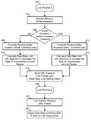
- FIG. 4is a flowchart illustrating a method of implementing a DRL mechanism on an Ethernet fabric, according to an embodiment of the present disclosure
- FIG. 5illustrates an underutilized buffer of an Ethernet switch, according to an embodiment of the present disclosure
- FIG. 6is a flowchart illustrating a method of modifying a DRL when the buffer of FIG. 5 is underutilized
- FIG. 7illustrates an overutilized buffer of an Ethernet switch, according to an embodiment of the present disclosure
- FIG. 8is a flowchart illustrating a method of modifying a DRL when the buffer of FIG. 7 is overutilized.
- FIG. 9is a block diagram illustrating an information handling system according to another embodiment of the present disclosure.
- FIG. 1illustrates an embodiment of an Ethernet fabric 100 that can include one or more information handling systems.
- the information handling systemmay include any instrumentality or aggregate of instrumentalities operable to compute, classify, process, transmit, receive, retrieve, originate, switch, store, display, manifest, detect, record, reproduce, handle, or utilize any form of information, intelligence, or data for business, scientific, control, entertainment, or other purposes.
- an information handling systemmay be a personal computer, a PDA, a consumer electronic device, a network server or storage device, a switch router or other network communication device, or any other suitable device and may vary in size, shape, performance, functionality, and price.
- the information handling systemmay include memory, one or more processing resources such as a central processing unit (CPU) or hardware or software control logic. Additional components of the information handling system may include one or more storage devices, one or more communications ports for communicating with external devices as well as various input and output (I/O) devices, such as a keyboard, a mouse, and a video display. The information handling system may also include one or more buses operable to transmit communications between the various hardware components.
- processing resourcessuch as a central processing unit (CPU) or hardware or software control logic.
- Additional components of the information handling systemmay include one or more storage devices, one or more communications ports for communicating with external devices as well as various input and output (I/O) devices, such as a keyboard, a mouse, and a video display.
- I/Oinput and output
- the information handling systemmay also include one or more buses operable to transmit communications between the various hardware components.
- Ethernet fabric 100operates to implement a priority-based flow control (PFC), as defined by the Institute of Electrical and Electronics Engineers (IEEE) standard 802.1Qbb, to provide a link level flow control mechanism that can be controlled independently for each class of service (CoS), as defined by IEEE standard 802.1p, and includes Ethernet switches 110 and 120 that are linked together by a transmit link 130 and by a receive link 140 .
- Ethernet switch 110includes eight transmit buffers 111 , 112 , 113 , 114 , 115 , 116 , 117 , and 118 .
- Each transmit buffer 111 - 118is associated with network traffic of a particular CoS 0-7, such that transmit buffer 111 is associated with CoS 0 traffic, transmit buffer 112 is associated with CoS 1 traffic, etc.
- Ethernet switch 110also includes a receive buffer 119 .
- Ethernet switch 120includes eight receive buffers 121 , 122 , 123 , 124 , 125 , 126 , 127 , and 128 .
- Each receive buffer 121 - 128is associated with network traffic of a particular CoS 0-7, such that receive buffer 121 is associated with CoS 0 traffic, receive buffer 122 is associated with CoS 1 traffic, etc.
- Ethernet switch 120also includes a transmit buffer 129 .
- Ethernet switches 110 and 120each include one or more additional sets of transmit buffers and receive buffers.
- switchincludes other types of networking equipment, such as a router, a hub, a bridge, a gateway, a repeater, another type of networking equipment, or a combination thereof.
- Ethernet switch 110 , Ethernet switch 120 , or bothimplement a buffer management scheme wherein each buffer is implemented as a separate buffer that is dedicated to the network traffic of the associated CoS.
- Ethernet switch 110 , Ethernet switch 120 , or bothimplement a buffer management scheme wherein the buffers share a common pool of memory, and each CoS uses a portion of the common pool of memory based on the network traffic flow through the ports that is associated with the particular CoS.
- Transmit buffers 111 - 118are each connected to a corresponding receive buffer 121 - 128 via transmit link 130 .
- Transmit link 130represents a particular physical data link that operates to transmit data from Ethernet switch 110 to Ethernet switch 120 , and is partitioned into eight virtual links 131 , 132 , 133 , 134 , 135 , 136 , 137 , and 138 , such that the transmit buffer 111 is connected to receive buffer 121 via virtual link 131 , transmit buffer 112 is connected to receive buffer 122 via virtual link 132 , etc.
- Transmit buffer 129is connected to receive buffer 119 via receive link 140 , and represents a particular physical data link that operates to transmit data from Ethernet switch 120 to Ethernet switch 110 , and can be partitioned into virtual links similar to virtual links 131 , 132 , 133 , 134 , 135 , 136 , 137 , and 138 , as needed or desired.
- Ethernet fabric 100operates to enforce a per CoS data rate limit (DRL).
- each of receive buffers 121 - 128measure a current buffer utilization (CBU) and compare the CBU with a threshold level. If the CBU is below the threshold, then the receive buffer can handle a higher data rate of traffic for the associated CoS, but if the CBU is above the threshold, then the receive buffer should handle a lower data rate of traffic for the associated CoS.
- Ethernet switch 120sends a DRL frame 150 over receive link 140 to Ethernet switch 110 .
- Ethernet switch 110When Ethernet switch 110 receives DRL frame 150 , then Ethernet switch 110 adjusts the egress bandwidth for the associated transmit buffer 111 - 118 to the DRL specified in the DRL frame, thereby matching the egress bandwidth to the data rate desired by the associated receive buffer 121 - 128 . Thus if DRL frame 150 indicates a lower DRL than a current data rate for one of the transmit buffers 121 - 128 , then Ethernet switch 110 reduces the egress bandwidth of the affected transmit buffer to the DRL specific in the DRL frame. If the DRL frame indicates a higher DRL than a current data rate for a transmit buffer, then Ethernet switch 110 increases the egress bandwidth of the affected transmit buffer to the DRL specific in the DRL frame. In a particular embodiment, Ethernet switch gradually increases the egress bandwidth of the affected transmit buffer to the DRL specific in the DRL frame.
- transmit link 130can be a 10 gigabits per second (10 Gb/s) link where CoSs 0-3 each have a maximum link speed of 2 Gb/s, and CoSs 4-7 each have a maximum link speed of 500 megabits per second (500 Mb/s).
- a particular linkcan have a DRL less than the maximum link speed associated with the link.
- virtual link 135can have a DRL that is 400 Mb/s.
- the congestion clearsthe CBU of receive buffer 125 can drop below the threshold for the receive buffer and Ethernet switch 120 can send DRL frame 150 to Ethernet switch 110 , indicating that the data rate for transmit buffer 115 can increase.
- DRL frame 150can indicate to Ethernet switch 110 that the data rate for transmit buffer 115 needs to be decreased.
- FIG. 2illustrates DRL frame 150 , and includes a header field 151 , an opcode field 152 , a class enable vector field 153 , eight DRL fields 154 - 161 , and a cyclic redundancy check (CRC) field 162 .
- Header field 151includes a destination Media Access Control (MAC) address, a source MAC address, and an EtherType for the DRL frame.
- Opcode field 152includes a coded identifier that the present frame is a DRL frame.
- Class enable vector field 153is an 8-bit field where each bit represents one of the eight CoS, and the class enable vector field acts as a mask for the eight DRL fields 154 - 161 .
- a particular bit of class enable vector field 153includes a digital “1,” then the associated DRL field 154 , 155 , 156 , 157 , 158 , 159 , 160 , or 161 is selected and the DRL of the selected DRL field is applied to the associated transmit buffer 111 - 118 . If a particular bit of class enable vector field 153 includes a digital “0,” then the associated DRL field 154 , 155 , 156 , 157 , 158 , 159 , 160 , or 161 is not selected and the DRL of the associated transmit buffer 111 - 118 is unchanged.
- FIG. 3illustrates data transfers and DRL frames communicated between Ethernet switch 110 and Ethernet switch 120 .
- CoS 0 datacan be communicated from CoS 0 transmit buffer 111 to CoS 0 receive buffer 121 at a data rate of 2 Gb/s.
- Receive buffer 121can measure the CBU and compare the CBU with the threshold level for the receive buffer.
- the CBUcan be determined to be above the threshold, and Ethernet switch 120 can place a DRL frame in transmit buffer 129 to be communicated to receive buffer 119 .
- the DRL framecan specify a lower DRL, such as a DRL of 1 Gb/s for CoS 0 data transfers.
- Ethernet switch 110When Ethernet switch 110 receives the DRL frame, the data rate for CoS data transfers can be lowered to 1 Gb/s, and at time 230 CoS 0 data can be communicated from CoS 0 transmit buffer 111 to CoS 0 receive buffer 121 at a data rate of 1 Gb/s.
- the CBUcan be determined to be below the threshold, and Ethernet switch 120 can place another DRL frame in transmit buffer 129 to be communicated to receive buffer 119 .
- the DRL framecan specify a higher DRL, such as a DRL of 1.5 Gb/s for CoS 0 data transfers.
- Ethernet switch 110When Ethernet switch 110 receives the DRL frame, the data rate for CoS data transfers can be raised to 1.5 Gb/s, and CoS 0 data can be communicated from CoS 0 transmit buffer 111 to CoS 0 receive buffer 121 at a data rate of 1.5 Gb/s at time 250 .
- FIG. 4illustrates a method of implementing a DRL mechanism on an Ethernet fabric, and begins in block 302 at a particular link partner, such as Ethernet switch 120 .
- the receive buffer utilizationis monitored at block 304 .
- each of receive buffers 121 - 128can monitor their respective CBUs.
- a determinationis made as to whether or not the buffer utilization is less than a buffer utilization threshold in decision block 306 . If not, the “NO” branch of decision block 306 is taken and the delta that the receive buffer utilization is above the threshold is computed in block 308 .
- a decrease DRL algorithmis used to calculate a new DRL to decrease the data transmission rate from the transmitting link partner in block 310 .
- the new DRLis included in a DRL frame and the DRL frame is sent to the transmitting link partner in block 316 .
- DRL frame 150can be sent from Ethernet switch 120 to Ethernet switch 110 .
- decision block 306If in decision block 306 the buffer utilization is less than the buffer utilization threshold, the “YES” branch of decision block 306 is taken and the delta that the receive buffer utilization is below the threshold is computed in block 312 .
- An increase DRL algorithmis used to calculate a new DRL to increase the data transmission rate from the transmitting link partner in block 314 , and processing continues in block 316 where the new DRL is included in the DRL frame and the DRL frame is sent to the transmitting link partner.
- each new DRLcan be included in the DRL frame.
- the methodproceeds in block 318 at the transmit link partner, such as Ethernet switch 110 .
- the transmit link partnerreceives the DRL frame in block 320 .
- Ethernet switch 110can receive DRL frame 150 at receive buffer 119 .
- the new DRLsare applied to adjust the data rates for the transmits buffers in block 322 .
- FIG. 5illustrates a buffer 402 that is underutilized.
- Buffer 402includes a threshold 404 .
- the thresholdcan be at a 50% level. In another embodiment, the threshold can be at a different level, as needed or desired.
- a CBU 406 for buffer 402is below threshold 404 , and a DRL increase factor 408 is shown as the difference between the threshold and the CBU.
- FIG. 6is a flowchart illustrating a method of modifying a DRL when buffer 402 is underutilized.
- the methodbegins at block 332 , and a decision is made as to whether or not a CBU for a buffer is less than a threshold for the buffer in decision block 334 . If not, the “NO” branch of decision block 334 is taken and processing proceeds at a decrease DRL algorithm in block 336 . If the CBU for the buffer is less than the threshold for the buffer, the “YES” branch of decision block 334 is taken, and a decision is made as to whether or not the current DRL is less than a maximum link speed in decision block 338 .
- the “NO” branch of decision block 338is taken, and the DRL is left unchanged in block 342 . If the current DRL is less than the maximum link speed, the “YES” branch of decision block 338 is taken, and a decision is made as to whether or not the CBU is greater than or equal to 10% of the previous buffer utilization in decision block 340 . If not, the “NO” branch of decision block 340 is taken, and the DRL is left unchanged in block 342 .
- the decision in decision block 340provides for a 10% factor in determining whether or not to modify a DRL. In this way, small changes in CBU do not trigger the sending of an excessive number of DRL packets. Another percentage can be used, as needed or desired. In another embodiment, instead of a particular percentage, a time period can be used to determine whether or not to modify a DRL.
- FIG. 7illustrates buffer 402 when it is overutilized.
- a CBU 410 for buffer 402is above threshold 404 , and a DRL decrease factor 408 is shown as the difference between the CBU and the threshold.
- FIG. 8illustrates a method of modifying a DRL when buffer 402 is overutilized. The method begins at block 352 , and a decision is made as to whether or not a CBU for a buffer is less than a threshold for the buffer in decision block 354 . If not, the “NO” branch of decision block 354 is taken and processing proceeds at an increase DRL algorithm in block 356 .
- the disclosed functions, devices, and methodsare applicable to various embodiments of switches, routers, and other network devices.
- the disclosed functions, devices, and methodsare applicable in an embodiment where a network device implements a buffer management scheme where each buffer is implemented as a separate buffer that is dedicated to the network traffic of the associated CoS.
- the disclosed functions, devices and methodsare applicable in an embodiment where the network device implements a buffer management scheme where the buffers share a common pool of memory, and each CoS uses a portion of the common pool of memory based on the network traffic flow through the ports that is associated with the particular CoS.
- a thresholdcan be applied to the common pool of memory on a per CoS basis, and a determination can be made whether or not a particular portion of the common pool associated with a particular CoS is above or below the associated threshold, and can modify the DRL for that CoS accordingly.
- a thresholdcan be applied to the common pool of memory. Then, if the current utilization of the common pool of memory exceeds the threshold, then a lower DRL can be applied to a particular CoS that is using the largest portion of the common pool of memory, and if the current utilization of the common pool of memory is lower than the threshold, then a higher DRL can be applied to a particular CoS that is using the smallest portion of the common pool of memory.
- FIG. 9is a block diagram illustrating an embodiment of an information handling system 500 , including a processor 510 , a chipset 520 , a memory 530 , a graphics interface 540 , an input/output (I/O) interface 550 , a disk controller 560 , a network interface 570 , and a disk emulator 580 .
- information handling system 500is used to carry out one or more of the methods described herein.
- one or more of the systems described hereinare implemented in the form of information handling system 500 .
- Chipset 520is connected to and supports processor 510 , allowing the processor to execute machine-executable code.
- information handling system 500includes one or more additional processors, and chipset 520 supports the multiple processors, allowing for simultaneous processing by each of the processors and permitting the exchange of information among the processors and the other elements of the information handling system.
- Chipset 520can be connected to processor 510 via a unique channel, or via a bus that shares information among the processor, the chipset, and other elements of information handling system 500 .
- Memory 530is connected to chipset 520 .
- Memory 530 and chipset 520can be connected via a unique channel, or via a bus that shares information among the chipset, the memory, and other elements of information handling system 500 .
- processor 510is connected to memory 530 via a unique channel.
- information handling system 500includes separate memory dedicated to each of the one or more additional processors.
- a non-limiting example of memory 530includes static random access memory (SRAM), dynamic random access memory (DRAM), non-volatile random access memory (NVRAM), read only memory (ROM), flash memory, another type of memory, or any combination thereof.
- Graphics interface 540is connected to chipset 520 . Graphics interface 540 and chipset 520 can be connected via a unique channel, or via a bus that shares information among the chipset, the graphics interface, and other elements of information handling system 500 . Graphics interface 540 is connected to a video display 542 . Other graphics interfaces (not illustrated) can also be used in addition to graphics interface 540 as needed or desired. Video display 542 includes one or more types of video displays, such as a flat panel display, another type of display device, or any combination thereof.
- I/O interface 550is connected to chipset 520 .
- I/O interface 550 and chipset 520can be connected via a unique channel, or via a bus that shares information among the chipset, the I/O interface, and other elements of information handling system 500 .
- Other I/O interfaces(not illustrated) can also be used in addition to I/O interface 550 as needed or desired.
- I/O interface 550is connected via an I/O interface 552 to one or more add-on resources 554 .
- Add-on resource 554is connected to a storage system 590 , and can also include another data storage system, a graphics interface, a network interface card (NIC), a sound/video processing card, another suitable add-on resource or any combination thereof.
- NICnetwork interface card
- I/O interface 550is also connected via I/O interface 552 to one or more platform fuses 556 and to a security resource 558 .
- Platform fuses 556function to set or modify the functionality of information handling system 500 in hardware.
- Security resource 558provides a secure cryptographic functionality and includes secure storage of cryptographic keys.
- a non-limiting example of security resource 558includes a Unified Security Hub (USH), a Trusted Platform Module (TPM), a General Purpose Encryption (GPE) engine, another security resource, or a combination thereof.
- Disk controller 560is connected to chipset 520 . Disk controller 560 and chipset 520 can be connected via a unique channel, or via a bus that shares information among the chipset, the disk controller, and other elements of information handling system 500 . Other disk controllers (not illustrated) can also be used in addition to disk controller 560 as needed or desired. Disk controller 560 includes a disk interface 562 . Disk controller 560 is connected to one or more disk drives via disk interface 562 . Such disk drives include a hard disk drive (HDD) 564 , and an optical disk drive (ODD) 566 , and can include one or more disk drive as needed or desired.
- HDDhard disk drive
- ODDoptical disk drive
- ODD 566can include a Read/Write Compact Disk (R/W-CD), a Read/Write Digital Video Disk (R/W-DVD), a Read/Write mini Digital Video Disk (R/W mini-DVD, another type of optical disk drive, or any combination thereof.
- disk controller 560is connected to disk emulator 580 .
- Disk emulator 580permits a solid-state drive 584 to be coupled to information handling system 500 via an external interface 582 .
- External interface 582can include industry standard busses such as USB or IEEE 1394 (Firewire) or proprietary busses, or any combination thereof.
- solid-state drive 584can be disposed within information handling system 500 .
- Network interface device 570is connected to I/O interface 550 .
- Network interface 570 and I/O interface 550can be coupled via a unique channel, or via a bus that shares information among the I/O interface, the network interface, and other elements of information handling system 500 .
- Other network interfacescan also be used in addition to network interface 570 as needed or desired.
- Network interface 570can be a network interface card (NIC) disposed within information handling system 500 , on a main circuit board such as a baseboard, a motherboard, or any combination thereof, integrated onto another component such as chipset 520 , in another suitable location, or any combination thereof.
- Network interface 570includes a network channel 572 that provide interfaces between information handling system 500 and other devices (not illustrated) that are external to information handling system 500 .
- Network interface 570can also include additional network channels (not illustrated).
- Information handling system 500includes one or more application programs 532 , and Basic Input/Output System and Firmware (BIOS/FW) code 534 .
- BIOS/FW code 534functions to initialize information handling system 500 on power up, to launch an operating system, and to manage input and output interactions between the operating system and the other elements of information handling system 500 .
- application programs 532 and BIOS/FW code 534reside in memory 530 , and include machine-executable code that is executed by processor 510 to perform various functions of information handling system 500 .
- application programs and BIOS/FW codereside in another storage medium of information handling system 500 .
- application programs and BIOS/FW codecan reside in HDD 564 , in a ROM (not illustrated) associated with information handling system 500 , in an option-ROM (not illustrated) associated with various devices of information handling system 500 , in storage system 590 , in a storage system (not illustrated) associated with network channel 572 , in another storage medium of information handling system 500 , or a combination thereof.
- Application programs 532 and BIOS/FW code 534can each be implemented as single programs, or as separate programs carrying out the various features as described herein.
- an information handling systemincludes any instrumentality or aggregate of instrumentalities operable to compute, classify, process, transmit, receive, retrieve, originate, switch, store, display, manifest, detect, record, reproduce, handle, or use any form of information, intelligence, or data for business, scientific, control, entertainment, or other purposes.
- an information handling systemcan be a personal computer, a consumer electronic device, a network server or storage device, a switch router, wireless router, or other network communication device, a network connected device (cellular telephone, tablet device, etc.), or any other suitable device, and can vary in size, shape, performance, price, and functionality.
- the information handling systemcan include memory (volatile (e.g.
- processing resourcessuch as a central processing unit (CPU), a graphics processing unit (GPU), hardware or software control logic, or any combination thereof.
- Additional components of the information handling systemcan include one or more storage devices, one or more communications ports for communicating with external devices, as well as, various input and output (I/O) devices, such as a keyboard, a mouse, a video/graphic display, or any combination thereof.
- the information handling systemcan also include one or more buses operable to transmit communications between the various hardware components. Portions of an information handling system may themselves be considered information handling systems.
- an information handling system devicemay be hardware such as, for example, an integrated circuit (such as an Application Specific Integrated Circuit (ASIC), a Field Programmable Gate Array (FPGA), a structured ASIC, or a device embedded on a larger chip), a card (such as a Peripheral Component Interface (PCI) card, a PCI-express card, a Personal Computer Memory Card International Association (PCMCIA) card, or other such expansion card), or a system (such as a motherboard, a system-on-a-chip (SoC), or a stand-alone device).
- an integrated circuitsuch as an Application Specific Integrated Circuit (ASIC), a Field Programmable Gate Array (FPGA), a structured ASIC, or a device embedded on a larger chip
- a cardsuch as a Peripheral Component Interface (PCI) card, a PCI-express card, a Personal Computer Memory Card International Association (PCMCIA) card, or other such expansion card
- PCIPeripheral Component Interface
- the device or modulecan include software, including firmware embedded at a device, such as a Pentium class or PowerPCTM brand processor, or other such device, or software capable of operating a relevant environment of the information handling system.
- the device or modulecan also include a combination of the foregoing examples of hardware or software.
- an information handling systemcan include an integrated circuit or a board-level product having portions thereof that can also be any combination of hardware and software.
- Devices, modules, resources, or programs that are in communication with one anotherneed not be in continuous communication with each other, unless expressly specified otherwise.
- devices, modules, resources, or programs that are in communication with one anothercan communicate directly or indirectly through one or more intermediaries.
Landscapes
- Engineering & Computer Science (AREA)
- Theoretical Computer Science (AREA)
- Computer Networks & Wireless Communication (AREA)
- Signal Processing (AREA)
- Physics & Mathematics (AREA)
- General Engineering & Computer Science (AREA)
- General Physics & Mathematics (AREA)
- Small-Scale Networks (AREA)
- Data Exchanges In Wide-Area Networks (AREA)
Abstract
Description
DRL=(Max_Link_Speed×(Threhold−CBU))+
in
DRL=Current_DRL−(Max_Link_Speed×(CBU−Threshold))
in
Claims (15)
Priority Applications (1)
| Application Number | Priority Date | Filing Date | Title |
|---|---|---|---|
| US15/056,550US9948567B2 (en) | 2011-06-24 | 2016-02-29 | System and method for dynamic rate control in Ethernet fabrics |
Applications Claiming Priority (2)
| Application Number | Priority Date | Filing Date | Title |
|---|---|---|---|
| US13/168,205US9300590B2 (en) | 2011-06-24 | 2011-06-24 | System and method for dynamic rate control in Ethernet fabrics |
| US15/056,550US9948567B2 (en) | 2011-06-24 | 2016-02-29 | System and method for dynamic rate control in Ethernet fabrics |
Related Parent Applications (1)
| Application Number | Title | Priority Date | Filing Date |
|---|---|---|---|
| US13/168,205ContinuationUS9300590B2 (en) | 2011-06-24 | 2011-06-24 | System and method for dynamic rate control in Ethernet fabrics |
Publications (2)
| Publication Number | Publication Date |
|---|---|
| US20160182389A1 US20160182389A1 (en) | 2016-06-23 |
| US9948567B2true US9948567B2 (en) | 2018-04-17 |
Family
ID=47361759
Family Applications (2)
| Application Number | Title | Priority Date | Filing Date |
|---|---|---|---|
| US13/168,205Active2032-12-17US9300590B2 (en) | 2011-06-24 | 2011-06-24 | System and method for dynamic rate control in Ethernet fabrics |
| US15/056,550ActiveUS9948567B2 (en) | 2011-06-24 | 2016-02-29 | System and method for dynamic rate control in Ethernet fabrics |
Family Applications Before (1)
| Application Number | Title | Priority Date | Filing Date |
|---|---|---|---|
| US13/168,205Active2032-12-17US9300590B2 (en) | 2011-06-24 | 2011-06-24 | System and method for dynamic rate control in Ethernet fabrics |
Country Status (1)
| Country | Link |
|---|---|
| US (2) | US9300590B2 (en) |
Families Citing this family (6)
| Publication number | Priority date | Publication date | Assignee | Title |
|---|---|---|---|---|
| US9571410B2 (en)* | 2013-04-09 | 2017-02-14 | International Business Machines Corporation | Credit-based link level flow control and credit exchange using DCBX |
| US9634944B2 (en) | 2013-10-24 | 2017-04-25 | Dell Products, Lp | Multi-level iSCSI QoS for target differentiated data in DCB networks |
| US10708819B2 (en)* | 2016-02-25 | 2020-07-07 | Telefonaktiebolaget Lm Ericsson (Publ) | Back-pressure control in a telecommunications network |
| WO2017146620A1 (en)* | 2016-02-25 | 2017-08-31 | Telefonaktiebolaget Lm Ericsson (Publ) | Congestion control in a telecommunications network |
| US11543967B2 (en)* | 2017-02-23 | 2023-01-03 | Samsung Electronics Co., Ltd. | Method for controlling BW SLA in NVME-of ethernet SSD storage systems |
| US10972396B2 (en)* | 2017-09-29 | 2021-04-06 | Hewlett Packard Enterprise Development Lp | Mapping network frame flows to classes of service to minimize network frame flow disruption |
Citations (20)
| Publication number | Priority date | Publication date | Assignee | Title |
|---|---|---|---|---|
| US6473867B2 (en) | 1991-08-20 | 2002-10-29 | Hitachi, Ltd. | Parity storage unit, in a disk array system, for generating updated parity data from received data records |
| US20060062233A1 (en)* | 2000-12-19 | 2006-03-23 | Chiaro Networks Ltd. | System and method for router queue and congestion management |
| US20060092845A1 (en)* | 2004-10-29 | 2006-05-04 | Broadcom Corporation | Service aware flow control |
| US7076606B2 (en) | 2002-09-20 | 2006-07-11 | Quantum Corporation | Accelerated RAID with rewind capability |
| US7340672B2 (en) | 2004-09-20 | 2008-03-04 | Intel Corporation | Providing data integrity for data streams |
| US20080288664A1 (en) | 2003-01-21 | 2008-11-20 | Nextio Inc. | Switching apparatus and method for link initialization in a shared i/o environment |
| US20080310342A1 (en) | 2007-06-12 | 2008-12-18 | Cisco Technology, Inc. | Addressing Messages in a Two-Tier Network |
| US7551559B1 (en)* | 2004-10-22 | 2009-06-23 | Cisco Technology, Inc. | System and method for performing security actions for inter-layer binding protocol traffic |
| US20090161584A1 (en) | 2006-08-30 | 2009-06-25 | Huawei Technologies Co., Ltd. | Method for a root path calculation in a shortest path bridge |
| US20090204757A1 (en) | 2008-02-11 | 2009-08-13 | Dell Products L.P. | Systems and Methods for Automatically Generating A Mirrored Storage Configuration For a Storage Array |
| US20100027420A1 (en) | 2008-07-31 | 2010-02-04 | Cisco Technology, Inc. | Dynamic distribution of virtual machines in a communication network |
| US20100061269A1 (en) | 2008-09-09 | 2010-03-11 | Cisco Technology, Inc. | Differentiated services for unicast and multicast frames in layer 2 topologies |
| US20100103819A1 (en)* | 2003-07-29 | 2010-04-29 | Samuels Allen R | Flow control system architecture |
| US20100165995A1 (en) | 2008-12-29 | 2010-07-01 | Juniper Networks, Inc. | Routing frames in a computer network using bridge identifiers |
| US20100189440A1 (en)* | 2009-01-28 | 2010-07-29 | Telefonaktiebolaget L M Ericsson (Publ) | Methods and Systems for Transmitting Data in Scalable Passive Optical Networks |
| US7783716B2 (en) | 2001-11-28 | 2010-08-24 | Emc Corporation | Systems and methods for implementing content sensitive routing over a wide area network (WAN) |
| US20100318647A1 (en) | 2009-06-10 | 2010-12-16 | At&T Intellectual Property I, L.P. | System and Method to Determine Network Usage |
| US20120026877A1 (en)* | 2010-07-30 | 2012-02-02 | Mayflower Communications Company, Inc. | High performance data transport system and method |
| US20120163175A1 (en)* | 2010-12-23 | 2012-06-28 | Brocade Communications Systems, Inc. | Ingress rate limiting |
| US8255515B1 (en)* | 2006-01-17 | 2012-08-28 | Marvell Israel (M.I.S.L.) Ltd. | Rate limiting per-flow of traffic to CPU on network switching and routing devices |
- 2011
- 2011-06-24USUS13/168,205patent/US9300590B2/enactiveActive
- 2016
- 2016-02-29USUS15/056,550patent/US9948567B2/enactiveActive
Patent Citations (20)
| Publication number | Priority date | Publication date | Assignee | Title |
|---|---|---|---|---|
| US6473867B2 (en) | 1991-08-20 | 2002-10-29 | Hitachi, Ltd. | Parity storage unit, in a disk array system, for generating updated parity data from received data records |
| US20060062233A1 (en)* | 2000-12-19 | 2006-03-23 | Chiaro Networks Ltd. | System and method for router queue and congestion management |
| US7783716B2 (en) | 2001-11-28 | 2010-08-24 | Emc Corporation | Systems and methods for implementing content sensitive routing over a wide area network (WAN) |
| US7076606B2 (en) | 2002-09-20 | 2006-07-11 | Quantum Corporation | Accelerated RAID with rewind capability |
| US20080288664A1 (en) | 2003-01-21 | 2008-11-20 | Nextio Inc. | Switching apparatus and method for link initialization in a shared i/o environment |
| US20100103819A1 (en)* | 2003-07-29 | 2010-04-29 | Samuels Allen R | Flow control system architecture |
| US7340672B2 (en) | 2004-09-20 | 2008-03-04 | Intel Corporation | Providing data integrity for data streams |
| US7551559B1 (en)* | 2004-10-22 | 2009-06-23 | Cisco Technology, Inc. | System and method for performing security actions for inter-layer binding protocol traffic |
| US20060092845A1 (en)* | 2004-10-29 | 2006-05-04 | Broadcom Corporation | Service aware flow control |
| US8255515B1 (en)* | 2006-01-17 | 2012-08-28 | Marvell Israel (M.I.S.L.) Ltd. | Rate limiting per-flow of traffic to CPU on network switching and routing devices |
| US20090161584A1 (en) | 2006-08-30 | 2009-06-25 | Huawei Technologies Co., Ltd. | Method for a root path calculation in a shortest path bridge |
| US20080310342A1 (en) | 2007-06-12 | 2008-12-18 | Cisco Technology, Inc. | Addressing Messages in a Two-Tier Network |
| US20090204757A1 (en) | 2008-02-11 | 2009-08-13 | Dell Products L.P. | Systems and Methods for Automatically Generating A Mirrored Storage Configuration For a Storage Array |
| US20100027420A1 (en) | 2008-07-31 | 2010-02-04 | Cisco Technology, Inc. | Dynamic distribution of virtual machines in a communication network |
| US20100061269A1 (en) | 2008-09-09 | 2010-03-11 | Cisco Technology, Inc. | Differentiated services for unicast and multicast frames in layer 2 topologies |
| US20100165995A1 (en) | 2008-12-29 | 2010-07-01 | Juniper Networks, Inc. | Routing frames in a computer network using bridge identifiers |
| US20100189440A1 (en)* | 2009-01-28 | 2010-07-29 | Telefonaktiebolaget L M Ericsson (Publ) | Methods and Systems for Transmitting Data in Scalable Passive Optical Networks |
| US20100318647A1 (en) | 2009-06-10 | 2010-12-16 | At&T Intellectual Property I, L.P. | System and Method to Determine Network Usage |
| US20120026877A1 (en)* | 2010-07-30 | 2012-02-02 | Mayflower Communications Company, Inc. | High performance data transport system and method |
| US20120163175A1 (en)* | 2010-12-23 | 2012-06-28 | Brocade Communications Systems, Inc. | Ingress rate limiting |
Also Published As
| Publication number | Publication date |
|---|---|
| US9300590B2 (en) | 2016-03-29 |
| US20120327774A1 (en) | 2012-12-27 |
| US20160182389A1 (en) | 2016-06-23 |
Similar Documents
| Publication | Publication Date | Title |
|---|---|---|
| US9948567B2 (en) | System and method for dynamic rate control in Ethernet fabrics | |
| US12073241B2 (en) | Learning of tunnel endpoint selections | |
| US8325713B2 (en) | System and method to enable large MTUs in data center ethernet networks | |
| US11494212B2 (en) | Technologies for adaptive platform resource assignment | |
| US9912616B2 (en) | Grouping tunnel endpoints of a bridge cluster | |
| US9559948B2 (en) | System and method for managing unknown flows in a flow-based switching device | |
| US9509597B2 (en) | System and method for dataplane extensibility in a flow-based switching device | |
| US8929255B2 (en) | System and method for input/output virtualization using virtualized switch aggregation zones | |
| US20150033222A1 (en) | Network Interface Card with Virtual Switch and Traffic Flow Policy Enforcement | |
| US10164885B2 (en) | Load balancing over multiple tunnel endpoints | |
| US20120042095A1 (en) | System and Method to Create Virtual Links for End-to-End Virtualization | |
| US20130223226A1 (en) | System and Method for Providing a Split Data Plane in a Flow-Based Switching Device | |
| US9325617B2 (en) | Overlay capabilities exchange using DCBX | |
| US9569383B2 (en) | Method of handling network traffic through optimization of receive side scaling | |
| US20130195113A1 (en) | System and Method for Network Switch Data Plane Virtualization | |
| US10193811B1 (en) | Flow distribution using telemetry and machine learning techniques | |
| US20240195749A1 (en) | Path selection for packet transmission | |
| EP3378201B1 (en) | Load balancing over multiple tunnel endpoints | |
| US20070002826A1 (en) | System implementing shared interface for network link aggregation and system management | |
| US20210224138A1 (en) | Packet processing with load imbalance handling | |
| CN120604500A (en) | Congestion notification in a multi-queue environment | |
| US12289240B2 (en) | Dynamic service rebalancing in network interface cards having processing units | |
| US20250036783A1 (en) | Network interface device-based memory access to reduce write amplification factor and provide attestation | |
| US20250086284A1 (en) | Scalable trusted platform module in programmable network interface devices | |
| US20230155988A1 (en) | Packet security over multiple networks |
Legal Events
| Date | Code | Title | Description |
|---|---|---|---|
| AS | Assignment | Owner name:BANK OF AMERICA, N.A., AS ADMINISTRATIVE AGENT, NORTH CAROLINA Free format text:SUPPLEMENT TO PATENT SECURITY AGREEMENT (ABL);ASSIGNORS:DELL PRODUCTS L.P.;DELL SOFTWARE INC.;WYSE TECHNOLOGY, L.L.C.;REEL/FRAME:038665/0001 Effective date:20160511 Owner name:THE BANK OF NEW YORK MELLON TRUST COMPANY, N.A., AS FIRST LIEN COLLATERAL AGENT, TEXAS Free format text:SUPPLEMENT TO PATENT SECURITY AGREEMENT (NOTES);ASSIGNORS:DELL SOFTWARE INC.;WYSE TECHNOLOGY, L.L.C.;DELL PRODUCTS L.P.;REEL/FRAME:038664/0908 Effective date:20160511 Owner name:BANK OF AMERICA, N.A., AS COLLATERAL AGENT, NORTH CAROLINA Free format text:SUPPLEMENT TO PATENT SECURITY AGREEMENT (TERM LOAN);ASSIGNORS:DELL PRODUCTS L.P.;DELL SOFTWARE INC.;WYSE TECHNOLOGY, L.L.C.;REEL/FRAME:038665/0041 Effective date:20160511 Owner name:THE BANK OF NEW YORK MELLON TRUST COMPANY, N.A., A Free format text:SUPPLEMENT TO PATENT SECURITY AGREEMENT (NOTES);ASSIGNORS:DELL SOFTWARE INC.;WYSE TECHNOLOGY, L.L.C.;DELL PRODUCTS L.P.;REEL/FRAME:038664/0908 Effective date:20160511 Owner name:BANK OF AMERICA, N.A., AS COLLATERAL AGENT, NORTH Free format text:SUPPLEMENT TO PATENT SECURITY AGREEMENT (TERM LOAN);ASSIGNORS:DELL PRODUCTS L.P.;DELL SOFTWARE INC.;WYSE TECHNOLOGY, L.L.C.;REEL/FRAME:038665/0041 Effective date:20160511 Owner name:BANK OF AMERICA, N.A., AS ADMINISTRATIVE AGENT, NO Free format text:SUPPLEMENT TO PATENT SECURITY AGREEMENT (ABL);ASSIGNORS:DELL PRODUCTS L.P.;DELL SOFTWARE INC.;WYSE TECHNOLOGY, L.L.C.;REEL/FRAME:038665/0001 Effective date:20160511 | |
| AS | Assignment | Owner name:SECUREWORKS, CORP., GEORGIA Free format text:RELEASE OF REEL 038665 FRAME 0001 (ABL);ASSIGNOR:BANK OF AMERICA, N.A., AS ADMINISTRATIVE AGENT;REEL/FRAME:040021/0348 Effective date:20160907 Owner name:WYSE TECHNOLOGY L.L.C., CALIFORNIA Free format text:RELEASE OF REEL 038665 FRAME 0001 (ABL);ASSIGNOR:BANK OF AMERICA, N.A., AS ADMINISTRATIVE AGENT;REEL/FRAME:040021/0348 Effective date:20160907 Owner name:DELL SOFTWARE INC., CALIFORNIA Free format text:RELEASE OF REEL 038665 FRAME 0001 (ABL);ASSIGNOR:BANK OF AMERICA, N.A., AS ADMINISTRATIVE AGENT;REEL/FRAME:040021/0348 Effective date:20160907 Owner name:DELL PRODUCTS L.P., TEXAS Free format text:RELEASE OF REEL 038665 FRAME 0001 (ABL);ASSIGNOR:BANK OF AMERICA, N.A., AS ADMINISTRATIVE AGENT;REEL/FRAME:040021/0348 Effective date:20160907 | |
| AS | Assignment | Owner name:SECUREWORKS, CORP., GEORGIA Free format text:RELEASE OF REEL 038665 FRAME 0041 (TL);ASSIGNOR:BANK OF AMERICA, N.A., AS COLLATERAL AGENT;REEL/FRAME:040028/0375 Effective date:20160907 Owner name:WYSE TECHNOLOGY L.L.C., CALIFORNIA Free format text:RELEASE OF REEL 038665 FRAME 0041 (TL);ASSIGNOR:BANK OF AMERICA, N.A., AS COLLATERAL AGENT;REEL/FRAME:040028/0375 Effective date:20160907 Owner name:DELL PRODUCTS L.P., TEXAS Free format text:RELEASE OF REEL 038665 FRAME 0041 (TL);ASSIGNOR:BANK OF AMERICA, N.A., AS COLLATERAL AGENT;REEL/FRAME:040028/0375 Effective date:20160907 Owner name:DELL SOFTWARE INC., CALIFORNIA Free format text:RELEASE OF REEL 038665 FRAME 0041 (TL);ASSIGNOR:BANK OF AMERICA, N.A., AS COLLATERAL AGENT;REEL/FRAME:040028/0375 Effective date:20160907 Owner name:WYSE TECHNOLOGY L.L.C., CALIFORNIA Free format text:RELEASE OF REEL 038664 FRAME 0908 (NOTE);ASSIGNOR:BANK OF NEW YORK MELLON TRUST COMPANY, N.A., AS COLLATERAL AGENT;REEL/FRAME:040027/0390 Effective date:20160907 Owner name:DELL SOFTWARE INC., CALIFORNIA Free format text:RELEASE OF REEL 038664 FRAME 0908 (NOTE);ASSIGNOR:BANK OF NEW YORK MELLON TRUST COMPANY, N.A., AS COLLATERAL AGENT;REEL/FRAME:040027/0390 Effective date:20160907 Owner name:DELL PRODUCTS L.P., TEXAS Free format text:RELEASE OF REEL 038664 FRAME 0908 (NOTE);ASSIGNOR:BANK OF NEW YORK MELLON TRUST COMPANY, N.A., AS COLLATERAL AGENT;REEL/FRAME:040027/0390 Effective date:20160907 Owner name:SECUREWORKS, CORP., GEORGIA Free format text:RELEASE OF REEL 038664 FRAME 0908 (NOTE);ASSIGNOR:BANK OF NEW YORK MELLON TRUST COMPANY, N.A., AS COLLATERAL AGENT;REEL/FRAME:040027/0390 Effective date:20160907 | |
| AS | Assignment | Owner name:CREDIT SUISSE AG, CAYMAN ISLANDS BRANCH, AS COLLATERAL AGENT, NORTH CAROLINA Free format text:SECURITY AGREEMENT;ASSIGNORS:ASAP SOFTWARE EXPRESS, INC.;AVENTAIL LLC;CREDANT TECHNOLOGIES, INC.;AND OTHERS;REEL/FRAME:040134/0001 Effective date:20160907 Owner name:THE BANK OF NEW YORK MELLON TRUST COMPANY, N.A., AS NOTES COLLATERAL AGENT, TEXAS Free format text:SECURITY AGREEMENT;ASSIGNORS:ASAP SOFTWARE EXPRESS, INC.;AVENTAIL LLC;CREDANT TECHNOLOGIES, INC.;AND OTHERS;REEL/FRAME:040136/0001 Effective date:20160907 Owner name:THE BANK OF NEW YORK MELLON TRUST COMPANY, N.A., A Free format text:SECURITY AGREEMENT;ASSIGNORS:ASAP SOFTWARE EXPRESS, INC.;AVENTAIL LLC;CREDANT TECHNOLOGIES, INC.;AND OTHERS;REEL/FRAME:040136/0001 Effective date:20160907 Owner name:CREDIT SUISSE AG, CAYMAN ISLANDS BRANCH, AS COLLAT Free format text:SECURITY AGREEMENT;ASSIGNORS:ASAP SOFTWARE EXPRESS, INC.;AVENTAIL LLC;CREDANT TECHNOLOGIES, INC.;AND OTHERS;REEL/FRAME:040134/0001 Effective date:20160907 | |
| STCF | Information on status: patent grant | Free format text:PATENTED CASE | |
| AS | Assignment | Owner name:THE BANK OF NEW YORK MELLON TRUST COMPANY, N.A., TEXAS Free format text:SECURITY AGREEMENT;ASSIGNORS:CREDANT TECHNOLOGIES, INC.;DELL INTERNATIONAL L.L.C.;DELL MARKETING L.P.;AND OTHERS;REEL/FRAME:049452/0223 Effective date:20190320 Owner name:THE BANK OF NEW YORK MELLON TRUST COMPANY, N.A., T Free format text:SECURITY AGREEMENT;ASSIGNORS:CREDANT TECHNOLOGIES, INC.;DELL INTERNATIONAL L.L.C.;DELL MARKETING L.P.;AND OTHERS;REEL/FRAME:049452/0223 Effective date:20190320 | |
| AS | Assignment | Owner name:THE BANK OF NEW YORK MELLON TRUST COMPANY, N.A., TEXAS Free format text:SECURITY AGREEMENT;ASSIGNORS:CREDANT TECHNOLOGIES INC.;DELL INTERNATIONAL L.L.C.;DELL MARKETING L.P.;AND OTHERS;REEL/FRAME:053546/0001 Effective date:20200409 | |
| MAFP | Maintenance fee payment | Free format text:PAYMENT OF MAINTENANCE FEE, 4TH YEAR, LARGE ENTITY (ORIGINAL EVENT CODE: M1551); ENTITY STATUS OF PATENT OWNER: LARGE ENTITY Year of fee payment:4 | |
| AS | Assignment | Owner name:WYSE TECHNOLOGY L.L.C., CALIFORNIA Free format text:RELEASE BY SECURED PARTY;ASSIGNOR:CREDIT SUISSE AG, CAYMAN ISLANDS BRANCH;REEL/FRAME:058216/0001 Effective date:20211101 Owner name:SCALEIO LLC, MASSACHUSETTS Free format text:RELEASE BY SECURED PARTY;ASSIGNOR:CREDIT SUISSE AG, CAYMAN ISLANDS BRANCH;REEL/FRAME:058216/0001 Effective date:20211101 Owner name:MOZY, INC., WASHINGTON Free format text:RELEASE BY SECURED PARTY;ASSIGNOR:CREDIT SUISSE AG, CAYMAN ISLANDS BRANCH;REEL/FRAME:058216/0001 Effective date:20211101 Owner name:MAGINATICS LLC, CALIFORNIA Free format text:RELEASE BY SECURED PARTY;ASSIGNOR:CREDIT SUISSE AG, CAYMAN ISLANDS BRANCH;REEL/FRAME:058216/0001 Effective date:20211101 Owner name:FORCE10 NETWORKS, INC., CALIFORNIA Free format text:RELEASE BY SECURED PARTY;ASSIGNOR:CREDIT SUISSE AG, CAYMAN ISLANDS BRANCH;REEL/FRAME:058216/0001 Effective date:20211101 Owner name:EMC IP HOLDING COMPANY LLC, TEXAS Free format text:RELEASE BY SECURED PARTY;ASSIGNOR:CREDIT SUISSE AG, CAYMAN ISLANDS BRANCH;REEL/FRAME:058216/0001 Effective date:20211101 Owner name:EMC CORPORATION, MASSACHUSETTS Free format text:RELEASE BY SECURED PARTY;ASSIGNOR:CREDIT SUISSE AG, CAYMAN ISLANDS BRANCH;REEL/FRAME:058216/0001 Effective date:20211101 Owner name:DELL SYSTEMS CORPORATION, TEXAS Free format text:RELEASE BY SECURED PARTY;ASSIGNOR:CREDIT SUISSE AG, CAYMAN ISLANDS BRANCH;REEL/FRAME:058216/0001 Effective date:20211101 Owner name:DELL SOFTWARE INC., CALIFORNIA Free format text:RELEASE BY SECURED PARTY;ASSIGNOR:CREDIT SUISSE AG, CAYMAN ISLANDS BRANCH;REEL/FRAME:058216/0001 Effective date:20211101 Owner name:DELL PRODUCTS L.P., TEXAS Free format text:RELEASE BY SECURED PARTY;ASSIGNOR:CREDIT SUISSE AG, CAYMAN ISLANDS BRANCH;REEL/FRAME:058216/0001 Effective date:20211101 Owner name:DELL MARKETING L.P., TEXAS Free format text:RELEASE BY SECURED PARTY;ASSIGNOR:CREDIT SUISSE AG, CAYMAN ISLANDS BRANCH;REEL/FRAME:058216/0001 Effective date:20211101 Owner name:DELL INTERNATIONAL, L.L.C., TEXAS Free format text:RELEASE BY SECURED PARTY;ASSIGNOR:CREDIT SUISSE AG, CAYMAN ISLANDS BRANCH;REEL/FRAME:058216/0001 Effective date:20211101 Owner name:DELL USA L.P., TEXAS Free format text:RELEASE BY SECURED PARTY;ASSIGNOR:CREDIT SUISSE AG, CAYMAN ISLANDS BRANCH;REEL/FRAME:058216/0001 Effective date:20211101 Owner name:CREDANT TECHNOLOGIES, INC., TEXAS Free format text:RELEASE BY SECURED PARTY;ASSIGNOR:CREDIT SUISSE AG, CAYMAN ISLANDS BRANCH;REEL/FRAME:058216/0001 Effective date:20211101 Owner name:AVENTAIL LLC, CALIFORNIA Free format text:RELEASE BY SECURED PARTY;ASSIGNOR:CREDIT SUISSE AG, CAYMAN ISLANDS BRANCH;REEL/FRAME:058216/0001 Effective date:20211101 Owner name:ASAP SOFTWARE EXPRESS, INC., ILLINOIS Free format text:RELEASE BY SECURED PARTY;ASSIGNOR:CREDIT SUISSE AG, CAYMAN ISLANDS BRANCH;REEL/FRAME:058216/0001 Effective date:20211101 | |
| AS | Assignment | Owner name:SCALEIO LLC, MASSACHUSETTS Free format text:RELEASE OF SECURITY INTEREST IN PATENTS PREVIOUSLY RECORDED AT REEL/FRAME (040136/0001);ASSIGNOR:THE BANK OF NEW YORK MELLON TRUST COMPANY, N.A., AS NOTES COLLATERAL AGENT;REEL/FRAME:061324/0001 Effective date:20220329 Owner name:EMC IP HOLDING COMPANY LLC (ON BEHALF OF ITSELF AND AS SUCCESSOR-IN-INTEREST TO MOZY, INC.), TEXAS Free format text:RELEASE OF SECURITY INTEREST IN PATENTS PREVIOUSLY RECORDED AT REEL/FRAME (040136/0001);ASSIGNOR:THE BANK OF NEW YORK MELLON TRUST COMPANY, N.A., AS NOTES COLLATERAL AGENT;REEL/FRAME:061324/0001 Effective date:20220329 Owner name:EMC CORPORATION (ON BEHALF OF ITSELF AND AS SUCCESSOR-IN-INTEREST TO MAGINATICS LLC), MASSACHUSETTS Free format text:RELEASE OF SECURITY INTEREST IN PATENTS PREVIOUSLY RECORDED AT REEL/FRAME (040136/0001);ASSIGNOR:THE BANK OF NEW YORK MELLON TRUST COMPANY, N.A., AS NOTES COLLATERAL AGENT;REEL/FRAME:061324/0001 Effective date:20220329 Owner name:DELL MARKETING CORPORATION (SUCCESSOR-IN-INTEREST TO FORCE10 NETWORKS, INC. AND WYSE TECHNOLOGY L.L.C.), TEXAS Free format text:RELEASE OF SECURITY INTEREST IN PATENTS PREVIOUSLY RECORDED AT REEL/FRAME (040136/0001);ASSIGNOR:THE BANK OF NEW YORK MELLON TRUST COMPANY, N.A., AS NOTES COLLATERAL AGENT;REEL/FRAME:061324/0001 Effective date:20220329 Owner name:DELL PRODUCTS L.P., TEXAS Free format text:RELEASE OF SECURITY INTEREST IN PATENTS PREVIOUSLY RECORDED AT REEL/FRAME (040136/0001);ASSIGNOR:THE BANK OF NEW YORK MELLON TRUST COMPANY, N.A., AS NOTES COLLATERAL AGENT;REEL/FRAME:061324/0001 Effective date:20220329 Owner name:DELL INTERNATIONAL L.L.C., TEXAS Free format text:RELEASE OF SECURITY INTEREST IN PATENTS PREVIOUSLY RECORDED AT REEL/FRAME (040136/0001);ASSIGNOR:THE BANK OF NEW YORK MELLON TRUST COMPANY, N.A., AS NOTES COLLATERAL AGENT;REEL/FRAME:061324/0001 Effective date:20220329 Owner name:DELL USA L.P., TEXAS Free format text:RELEASE OF SECURITY INTEREST IN PATENTS PREVIOUSLY RECORDED AT REEL/FRAME (040136/0001);ASSIGNOR:THE BANK OF NEW YORK MELLON TRUST COMPANY, N.A., AS NOTES COLLATERAL AGENT;REEL/FRAME:061324/0001 Effective date:20220329 Owner name:DELL MARKETING L.P. (ON BEHALF OF ITSELF AND AS SUCCESSOR-IN-INTEREST TO CREDANT TECHNOLOGIES, INC.), TEXAS Free format text:RELEASE OF SECURITY INTEREST IN PATENTS PREVIOUSLY RECORDED AT REEL/FRAME (040136/0001);ASSIGNOR:THE BANK OF NEW YORK MELLON TRUST COMPANY, N.A., AS NOTES COLLATERAL AGENT;REEL/FRAME:061324/0001 Effective date:20220329 Owner name:DELL MARKETING CORPORATION (SUCCESSOR-IN-INTEREST TO ASAP SOFTWARE EXPRESS, INC.), TEXAS Free format text:RELEASE OF SECURITY INTEREST IN PATENTS PREVIOUSLY RECORDED AT REEL/FRAME (040136/0001);ASSIGNOR:THE BANK OF NEW YORK MELLON TRUST COMPANY, N.A., AS NOTES COLLATERAL AGENT;REEL/FRAME:061324/0001 Effective date:20220329 | |
| AS | Assignment | Owner name:SCALEIO LLC, MASSACHUSETTS Free format text:RELEASE OF SECURITY INTEREST IN PATENTS PREVIOUSLY RECORDED AT REEL/FRAME (045455/0001);ASSIGNOR:THE BANK OF NEW YORK MELLON TRUST COMPANY, N.A., AS NOTES COLLATERAL AGENT;REEL/FRAME:061753/0001 Effective date:20220329 Owner name:EMC IP HOLDING COMPANY LLC (ON BEHALF OF ITSELF AND AS SUCCESSOR-IN-INTEREST TO MOZY, INC.), TEXAS Free format text:RELEASE OF SECURITY INTEREST IN PATENTS PREVIOUSLY RECORDED AT REEL/FRAME (045455/0001);ASSIGNOR:THE BANK OF NEW YORK MELLON TRUST COMPANY, N.A., AS NOTES COLLATERAL AGENT;REEL/FRAME:061753/0001 Effective date:20220329 Owner name:EMC CORPORATION (ON BEHALF OF ITSELF AND AS SUCCESSOR-IN-INTEREST TO MAGINATICS LLC), MASSACHUSETTS Free format text:RELEASE OF SECURITY INTEREST IN PATENTS PREVIOUSLY RECORDED AT REEL/FRAME (045455/0001);ASSIGNOR:THE BANK OF NEW YORK MELLON TRUST COMPANY, N.A., AS NOTES COLLATERAL AGENT;REEL/FRAME:061753/0001 Effective date:20220329 Owner name:DELL MARKETING CORPORATION (SUCCESSOR-IN-INTEREST TO FORCE10 NETWORKS, INC. AND WYSE TECHNOLOGY L.L.C.), TEXAS Free format text:RELEASE OF SECURITY INTEREST IN PATENTS PREVIOUSLY RECORDED AT REEL/FRAME (045455/0001);ASSIGNOR:THE BANK OF NEW YORK MELLON TRUST COMPANY, N.A., AS NOTES COLLATERAL AGENT;REEL/FRAME:061753/0001 Effective date:20220329 Owner name:DELL PRODUCTS L.P., TEXAS Free format text:RELEASE OF SECURITY INTEREST IN PATENTS PREVIOUSLY RECORDED AT REEL/FRAME (045455/0001);ASSIGNOR:THE BANK OF NEW YORK MELLON TRUST COMPANY, N.A., AS NOTES COLLATERAL AGENT;REEL/FRAME:061753/0001 Effective date:20220329 Owner name:DELL INTERNATIONAL L.L.C., TEXAS Free format text:RELEASE OF SECURITY INTEREST IN PATENTS PREVIOUSLY RECORDED AT REEL/FRAME (045455/0001);ASSIGNOR:THE BANK OF NEW YORK MELLON TRUST COMPANY, N.A., AS NOTES COLLATERAL AGENT;REEL/FRAME:061753/0001 Effective date:20220329 Owner name:DELL USA L.P., TEXAS Free format text:RELEASE OF SECURITY INTEREST IN PATENTS PREVIOUSLY RECORDED AT REEL/FRAME (045455/0001);ASSIGNOR:THE BANK OF NEW YORK MELLON TRUST COMPANY, N.A., AS NOTES COLLATERAL AGENT;REEL/FRAME:061753/0001 Effective date:20220329 Owner name:DELL MARKETING L.P. (ON BEHALF OF ITSELF AND AS SUCCESSOR-IN-INTEREST TO CREDANT TECHNOLOGIES, INC.), TEXAS Free format text:RELEASE OF SECURITY INTEREST IN PATENTS PREVIOUSLY RECORDED AT REEL/FRAME (045455/0001);ASSIGNOR:THE BANK OF NEW YORK MELLON TRUST COMPANY, N.A., AS NOTES COLLATERAL AGENT;REEL/FRAME:061753/0001 Effective date:20220329 Owner name:DELL MARKETING CORPORATION (SUCCESSOR-IN-INTEREST TO ASAP SOFTWARE EXPRESS, INC.), TEXAS Free format text:RELEASE OF SECURITY INTEREST IN PATENTS PREVIOUSLY RECORDED AT REEL/FRAME (045455/0001);ASSIGNOR:THE BANK OF NEW YORK MELLON TRUST COMPANY, N.A., AS NOTES COLLATERAL AGENT;REEL/FRAME:061753/0001 Effective date:20220329 | |
| AS | Assignment | Owner name:DELL MARKETING L.P. (ON BEHALF OF ITSELF AND AS SUCCESSOR-IN-INTEREST TO CREDANT TECHNOLOGIES, INC.), TEXAS Free format text:RELEASE OF SECURITY INTEREST IN PATENTS PREVIOUSLY RECORDED AT REEL/FRAME (053546/0001);ASSIGNOR:THE BANK OF NEW YORK MELLON TRUST COMPANY, N.A., AS NOTES COLLATERAL AGENT;REEL/FRAME:071642/0001 Effective date:20220329 Owner name:DELL INTERNATIONAL L.L.C., TEXAS Free format text:RELEASE OF SECURITY INTEREST IN PATENTS PREVIOUSLY RECORDED AT REEL/FRAME (053546/0001);ASSIGNOR:THE BANK OF NEW YORK MELLON TRUST COMPANY, N.A., AS NOTES COLLATERAL AGENT;REEL/FRAME:071642/0001 Effective date:20220329 Owner name:DELL PRODUCTS L.P., TEXAS Free format text:RELEASE OF SECURITY INTEREST IN PATENTS PREVIOUSLY RECORDED AT REEL/FRAME (053546/0001);ASSIGNOR:THE BANK OF NEW YORK MELLON TRUST COMPANY, N.A., AS NOTES COLLATERAL AGENT;REEL/FRAME:071642/0001 Effective date:20220329 Owner name:DELL USA L.P., TEXAS Free format text:RELEASE OF SECURITY INTEREST IN PATENTS PREVIOUSLY RECORDED AT REEL/FRAME (053546/0001);ASSIGNOR:THE BANK OF NEW YORK MELLON TRUST COMPANY, N.A., AS NOTES COLLATERAL AGENT;REEL/FRAME:071642/0001 Effective date:20220329 Owner name:EMC CORPORATION, MASSACHUSETTS Free format text:RELEASE OF SECURITY INTEREST IN PATENTS PREVIOUSLY RECORDED AT REEL/FRAME (053546/0001);ASSIGNOR:THE BANK OF NEW YORK MELLON TRUST COMPANY, N.A., AS NOTES COLLATERAL AGENT;REEL/FRAME:071642/0001 Effective date:20220329 Owner name:DELL MARKETING CORPORATION (SUCCESSOR-IN-INTEREST TO FORCE10 NETWORKS, INC. AND WYSE TECHNOLOGY L.L.C.), TEXAS Free format text:RELEASE OF SECURITY INTEREST IN PATENTS PREVIOUSLY RECORDED AT REEL/FRAME (053546/0001);ASSIGNOR:THE BANK OF NEW YORK MELLON TRUST COMPANY, N.A., AS NOTES COLLATERAL AGENT;REEL/FRAME:071642/0001 Effective date:20220329 Owner name:EMC IP HOLDING COMPANY LLC, TEXAS Free format text:RELEASE OF SECURITY INTEREST IN PATENTS PREVIOUSLY RECORDED AT REEL/FRAME (053546/0001);ASSIGNOR:THE BANK OF NEW YORK MELLON TRUST COMPANY, N.A., AS NOTES COLLATERAL AGENT;REEL/FRAME:071642/0001 Effective date:20220329 | |
| MAFP | Maintenance fee payment | Free format text:PAYMENT OF MAINTENANCE FEE, 8TH YEAR, LARGE ENTITY (ORIGINAL EVENT CODE: M1552); ENTITY STATUS OF PATENT OWNER: LARGE ENTITY Year of fee payment:8 |