US9943847B2 - Microfluidic system including a bubble valve for regulating fluid flow through a microchannel - Google Patents
Microfluidic system including a bubble valve for regulating fluid flow through a microchannelDownload PDFInfo
- Publication number
- US9943847B2 US9943847B2US14/689,508US201514689508AUS9943847B2US 9943847 B2US9943847 B2US 9943847B2US 201514689508 AUS201514689508 AUS 201514689508AUS 9943847 B2US9943847 B2US 9943847B2
- Authority
- US
- United States
- Prior art keywords
- microchannel
- reservoir
- bubble
- actuator
- liquid
- Prior art date
- Legal status (The legal status is an assumption and is not a legal conclusion. Google has not performed a legal analysis and makes no representation as to the accuracy of the status listed.)
- Expired - Lifetime
Links
- 239000012530fluidSubstances0.000titleclaimsabstractdescription43
- 230000001105regulatory effectEffects0.000titleabstractdescription16
- 239000007788liquidSubstances0.000claimsabstractdescription90
- 239000012528membraneSubstances0.000claimsabstractdescription7
- 239000002245particleSubstances0.000claimsdescription36
- 230000001965increasing effectEffects0.000claimsdescription11
- 239000000758substrateSubstances0.000claimsdescription2
- 230000005499meniscusEffects0.000abstractdescription51
- 239000007789gasSubstances0.000description50
- 239000000126substanceSubstances0.000description19
- 238000000034methodMethods0.000description16
- 238000005259measurementMethods0.000description13
- 230000002209hydrophobic effectEffects0.000description11
- 238000002347injectionMethods0.000description9
- 239000007924injectionSubstances0.000description9
- 238000004458analytical methodMethods0.000description8
- 238000012546transferMethods0.000description8
- 230000008569processEffects0.000description7
- 230000001276controlling effectEffects0.000description6
- 238000012545processingMethods0.000description6
- 238000000926separation methodMethods0.000description6
- 238000003786synthesis reactionMethods0.000description6
- 238000004891communicationMethods0.000description5
- 238000002156mixingMethods0.000description5
- 230000009467reductionEffects0.000description5
- 230000001052transient effectEffects0.000description5
- 230000004913activationEffects0.000description4
- 230000033228biological regulationEffects0.000description4
- 239000003153chemical reaction reagentSubstances0.000description4
- 238000010438heat treatmentMethods0.000description4
- 230000002829reductive effectEffects0.000description4
- 230000015572biosynthetic processEffects0.000description3
- 230000007423decreaseEffects0.000description3
- 230000003247decreasing effectEffects0.000description3
- 238000001962electrophoresisMethods0.000description3
- 238000004519manufacturing processMethods0.000description3
- 230000000717retained effectEffects0.000description3
- 239000000725suspensionSubstances0.000description3
- 238000004873anchoringMethods0.000description2
- 238000001816coolingMethods0.000description2
- 238000006073displacement reactionMethods0.000description2
- 230000000694effectsEffects0.000description2
- 230000006872improvementEffects0.000description2
- 239000002243precursorSubstances0.000description2
- 230000002411adverseEffects0.000description1
- 230000008901benefitEffects0.000description1
- 230000000903blocking effectEffects0.000description1
- 238000006243chemical reactionMethods0.000description1
- 239000013626chemical specieSubstances0.000description1
- 239000002894chemical wasteSubstances0.000description1
- 150000001875compoundsChemical class0.000description1
- 239000000470constituentSubstances0.000description1
- 238000010276constructionMethods0.000description1
- 239000000356contaminantSubstances0.000description1
- 230000009849deactivationEffects0.000description1
- 238000001514detection methodMethods0.000description1
- 238000009792diffusion processMethods0.000description1
- 229940000406drug candidateDrugs0.000description1
- 238000007876drug discoveryMethods0.000description1
- 238000005370electroosmosisMethods0.000description1
- 238000000684flow cytometryMethods0.000description1
- 230000006870functionEffects0.000description1
- 238000013537high throughput screeningMethods0.000description1
- 238000012988high-throughput synthesisMethods0.000description1
- 230000001939inductive effectEffects0.000description1
- 230000000670limiting effectEffects0.000description1
- 230000005012migrationEffects0.000description1
- 238000013508migrationMethods0.000description1
- 239000000203mixtureSubstances0.000description1
- 239000002547new drugSubstances0.000description1
- 230000009057passive transportEffects0.000description1
- 230000037361pathwayEffects0.000description1
- 230000004044responseEffects0.000description1
- 239000000523sampleSubstances0.000description1
- 238000007789sealingMethods0.000description1
- 238000012163sequencing techniqueMethods0.000description1
- 230000032258transportEffects0.000description1
- 239000011800void materialSubstances0.000description1
- 239000002699waste materialSubstances0.000description1
Images


Classifications
- B—PERFORMING OPERATIONS; TRANSPORTING
- B01—PHYSICAL OR CHEMICAL PROCESSES OR APPARATUS IN GENERAL
- B01L—CHEMICAL OR PHYSICAL LABORATORY APPARATUS FOR GENERAL USE
- B01L3/00—Containers or dishes for laboratory use, e.g. laboratory glassware; Droppers
- B01L3/50—Containers for the purpose of retaining a material to be analysed, e.g. test tubes
- B01L3/502—Containers for the purpose of retaining a material to be analysed, e.g. test tubes with fluid transport, e.g. in multi-compartment structures
- B01L3/5027—Containers for the purpose of retaining a material to be analysed, e.g. test tubes with fluid transport, e.g. in multi-compartment structures by integrated microfluidic structures, i.e. dimensions of channels and chambers are such that surface tension forces are important, e.g. lab-on-a-chip
- B01L3/502746—Containers for the purpose of retaining a material to be analysed, e.g. test tubes with fluid transport, e.g. in multi-compartment structures by integrated microfluidic structures, i.e. dimensions of channels and chambers are such that surface tension forces are important, e.g. lab-on-a-chip characterised by the means for controlling flow resistance, e.g. flow controllers, baffles
- B—PERFORMING OPERATIONS; TRANSPORTING
- B01—PHYSICAL OR CHEMICAL PROCESSES OR APPARATUS IN GENERAL
- B01L—CHEMICAL OR PHYSICAL LABORATORY APPARATUS FOR GENERAL USE
- B01L3/00—Containers or dishes for laboratory use, e.g. laboratory glassware; Droppers
- B01L3/50—Containers for the purpose of retaining a material to be analysed, e.g. test tubes
- B01L3/502—Containers for the purpose of retaining a material to be analysed, e.g. test tubes with fluid transport, e.g. in multi-compartment structures
- B01L3/5027—Containers for the purpose of retaining a material to be analysed, e.g. test tubes with fluid transport, e.g. in multi-compartment structures by integrated microfluidic structures, i.e. dimensions of channels and chambers are such that surface tension forces are important, e.g. lab-on-a-chip
- B01L3/502738—Containers for the purpose of retaining a material to be analysed, e.g. test tubes with fluid transport, e.g. in multi-compartment structures by integrated microfluidic structures, i.e. dimensions of channels and chambers are such that surface tension forces are important, e.g. lab-on-a-chip characterised by integrated valves
- F—MECHANICAL ENGINEERING; LIGHTING; HEATING; WEAPONS; BLASTING
- F16—ENGINEERING ELEMENTS AND UNITS; GENERAL MEASURES FOR PRODUCING AND MAINTAINING EFFECTIVE FUNCTIONING OF MACHINES OR INSTALLATIONS; THERMAL INSULATION IN GENERAL
- F16K—VALVES; TAPS; COCKS; ACTUATING-FLOATS; DEVICES FOR VENTING OR AERATING
- F16K99/00—Subject matter not provided for in other groups of this subclass
- F16K99/0001—Microvalves
- F16K99/0003—Constructional types of microvalves; Details of the cutting-off member
- F16K99/0019—Valves using a microdroplet or microbubble as the valve member
- F—MECHANICAL ENGINEERING; LIGHTING; HEATING; WEAPONS; BLASTING
- F16—ENGINEERING ELEMENTS AND UNITS; GENERAL MEASURES FOR PRODUCING AND MAINTAINING EFFECTIVE FUNCTIONING OF MACHINES OR INSTALLATIONS; THERMAL INSULATION IN GENERAL
- F16K—VALVES; TAPS; COCKS; ACTUATING-FLOATS; DEVICES FOR VENTING OR AERATING
- F16K99/00—Subject matter not provided for in other groups of this subclass
- F16K99/0001—Microvalves
- F16K99/0034—Operating means specially adapted for microvalves
- F16K99/0055—Operating means specially adapted for microvalves actuated by fluids
- F16K99/0061—Operating means specially adapted for microvalves actuated by fluids actuated by an expanding gas or liquid volume
- B—PERFORMING OPERATIONS; TRANSPORTING
- B01—PHYSICAL OR CHEMICAL PROCESSES OR APPARATUS IN GENERAL
- B01L—CHEMICAL OR PHYSICAL LABORATORY APPARATUS FOR GENERAL USE
- B01L2200/00—Solutions for specific problems relating to chemical or physical laboratory apparatus
- B01L2200/06—Fluid handling related problems
- B01L2200/0605—Metering of fluids
- B—PERFORMING OPERATIONS; TRANSPORTING
- B01—PHYSICAL OR CHEMICAL PROCESSES OR APPARATUS IN GENERAL
- B01L—CHEMICAL OR PHYSICAL LABORATORY APPARATUS FOR GENERAL USE
- B01L2300/00—Additional constructional details
- B01L2300/08—Geometry, shape and general structure
- B01L2300/0809—Geometry, shape and general structure rectangular shaped
- B01L2300/0816—Cards, e.g. flat sample carriers usually with flow in two horizontal directions
- B—PERFORMING OPERATIONS; TRANSPORTING
- B01—PHYSICAL OR CHEMICAL PROCESSES OR APPARATUS IN GENERAL
- B01L—CHEMICAL OR PHYSICAL LABORATORY APPARATUS FOR GENERAL USE
- B01L2300/00—Additional constructional details
- B01L2300/08—Geometry, shape and general structure
- B01L2300/0848—Specific forms of parts of containers
- B01L2300/0858—Side walls
- B—PERFORMING OPERATIONS; TRANSPORTING
- B01—PHYSICAL OR CHEMICAL PROCESSES OR APPARATUS IN GENERAL
- B01L—CHEMICAL OR PHYSICAL LABORATORY APPARATUS FOR GENERAL USE
- B01L2400/00—Moving or stopping fluids
- B01L2400/06—Valves, specific forms thereof
- B—PERFORMING OPERATIONS; TRANSPORTING
- B01—PHYSICAL OR CHEMICAL PROCESSES OR APPARATUS IN GENERAL
- B01L—CHEMICAL OR PHYSICAL LABORATORY APPARATUS FOR GENERAL USE
- B01L2400/00—Moving or stopping fluids
- B01L2400/08—Regulating or influencing the flow resistance
- B01L2400/082—Active control of flow resistance, e.g. flow controllers
- B—PERFORMING OPERATIONS; TRANSPORTING
- B01—PHYSICAL OR CHEMICAL PROCESSES OR APPARATUS IN GENERAL
- B01L—CHEMICAL OR PHYSICAL LABORATORY APPARATUS FOR GENERAL USE
- B01L3/00—Containers or dishes for laboratory use, e.g. laboratory glassware; Droppers
- B01L3/50—Containers for the purpose of retaining a material to be analysed, e.g. test tubes
- B01L3/502—Containers for the purpose of retaining a material to be analysed, e.g. test tubes with fluid transport, e.g. in multi-compartment structures
- B01L3/5027—Containers for the purpose of retaining a material to be analysed, e.g. test tubes with fluid transport, e.g. in multi-compartment structures by integrated microfluidic structures, i.e. dimensions of channels and chambers are such that surface tension forces are important, e.g. lab-on-a-chip
- B01L3/502715—Containers for the purpose of retaining a material to be analysed, e.g. test tubes with fluid transport, e.g. in multi-compartment structures by integrated microfluidic structures, i.e. dimensions of channels and chambers are such that surface tension forces are important, e.g. lab-on-a-chip characterised by interfacing components, e.g. fluidic, electrical, optical or mechanical interfaces
- F—MECHANICAL ENGINEERING; LIGHTING; HEATING; WEAPONS; BLASTING
- F16—ENGINEERING ELEMENTS AND UNITS; GENERAL MEASURES FOR PRODUCING AND MAINTAINING EFFECTIVE FUNCTIONING OF MACHINES OR INSTALLATIONS; THERMAL INSULATION IN GENERAL
- F16K—VALVES; TAPS; COCKS; ACTUATING-FLOATS; DEVICES FOR VENTING OR AERATING
- F16K99/00—Subject matter not provided for in other groups of this subclass
- F16K2099/0082—Microvalves adapted for a particular use
- F16K2099/0084—Chemistry or biology, e.g. "lab-on-a-chip" technology
Definitions
- the present inventionrelates to microscale fluid handling devices and systems. More particularly, the present invention relates to a method and system for controlling liquid flow in a microchannel by the introduction of a gas bubble to a microfluidic system.
- Microfluidic devices and systemsprovide improved methods of performing chemical, biochemical and biological analysis and synthesis. Microfluidic devices and systems allow for the performance of multi-step, multi-species chemical operations in chip-based micro chemical analysis systems.
- Chip-based microfluidic systemsgenerally comprise conventional ‘microfluidic’ elements, particularly capable of handling and analyzing chemical and biological specimens.
- microfluidic in the artrefers to systems or devices having a network of processing nodes, chambers and reservoirs connected by channels, in which the channels have typical cross-sectional dimensions in the range between about 1.0 ⁇ m and about 500 ⁇ m. In the art, channels having these cross-sectional dimensions are referred to as ‘microchannels’.
- Downscaling dimensionsallows for diffusional processes, such as heating, cooling and passive transport of species (diffusional mass-transport), to proceed faster.
- diffusional processessuch as heating, cooling and passive transport of species (diffusional mass-transport)
- thermal processing of liquidswhich is typically a required step in chemical synthesis and analysis.
- thermal processing of liquidsis accelerated in a microchannel due to reduced diffusional distances.
- Another example of the efficiency of microfluidic systemsis the mixing of dissolved species in a liquid, a process that is also diffusion limited.
- Milliliter-sized systemstypically require milliliter volumes of these substances, while microliter sized microfluidic systems only require microliters volumes.
- the ability to perform these processes using smaller volumesresults in significant cost savings, allowing the economic operation of chemical synthesis and analysis operations.
- the amount of chemical waste produced during the chemical operationsis correspondingly reduced.
- a flow control devicemay be used to regulate the flow of liquid through a microchannel. Regulation includes control of flow rate, impeding of flow, switching of flows between various input channels and output channels as well as volumetric dosing.
- U.S. Pat. No. 6,062,681describes a bubble valve for a liquid flow channel in which the flow of a liquid is controlled by the generation of a gas bubble in the channel using a heater placed in the liquid. As the heater is activated, a bubble is formed which can be enlarged or reduced in size by increasing or decreasing, respectively, the temperature of the heater.
- the described systempresents a number of disadvantages, namely, the required power to operate the valve and the inherent requirement that liquid in the channel be heated upon passing the valve. Even small increases in liquid temperature, by only a couple of degrees, can have disastrous effects on the highly heat sensitive biochemical substances present in the liquids to be controlled in many microfluidic systems.
- the required on-chip electric circuitry for the heaterincreases the complexity of the described valve and consequently results in unacceptably high costs, particularly if the fluidic system employing the bubble valve only used for a single application.
- valves in the prior artuse electrochemical means to produce a bubble in a liquid.
- the present inventionprovides a bubble valve for controlling, regulating or varying fluid flow through a microfluidic system.
- the bubble valveregulates fluid flow through a channel using an externally operated mechanical or pneumatic actuator.
- the actuatorcauses a deflection of a fluid meniscus into the interior of the channel to regulate liquid flow.
- the actuatormay mechanically force a gas bubble into a fluid carrying microchannel to inhibit liquid flow or to cause liquid flow by applying a sufficiently high pressure to the meniscus.
- the bubble valveeffectively controls the flow of liquids in microfluidic systems, without heating the fluid and without complex on-chip circuitry.
- the microfluidic systemincludes a microchannel and a sealed, gas-filled reservoir positioned adjacent to and connected to the microchannel.
- the gas filled reservoirhas a movable wall and a meniscus formed by a liquid in the microchannel that forms an interface between the reservoir and the microchannel interior.
- the meniscusmay form a portion of the side wall of the microchannel.
- An external mechanical actuatormay be used to deflect the movable wall of the reservoir. As the movable wall is deflected, the volume of the reservoir decreases and the gas pressure inside the reservoir increases, causing the meniscus to deflect into the microchannel, thereby modifying the cross-sectional area of the microchannel and consequently varying the flow of liquid through the channel.
- the increased pressure in the reservoirpushes gas from the reservoir into the microchannel.
- the gasmay result in a local gas bubble being forced into the microchannel from the gas-filled reservoir.
- the resulting gas bubbleoccupies a portion of the cross-section of the channel, allowing liquid flow through the channel to be effectively controlled by controlling the size of the gas bubble via the external actuator.
- the meniscusmay comprise a virtual wall formed in a side wall of the microchannel.
- the virtual wallis a meniscus formed by a liquid in the microchannel that fills an aperture formed in the side wall of the microchannel and essentially replaces the removed portion of the side wall without affecting the properties of liquid flow through the channel.
- a gas bubblecan be forced into the channel by applying a gas pressure at the opening using an external pneumatic actuator. The gas pressure forces the meniscus inside the channel, which varies the flow of liquid through the channel interior.
- the microchannelincludes a hydrophobic patch spanning the width of the microchannel at the location where the gas bubble is introduced to enhanced on-off switching of the bubble valve.
- the hydrophobic patchanchors the bubble in a particular location in the microchannel. If the introduced gas bubble covers the whole area of the patch, the bubble is effectively retained by capillary forces and blocks any liquid flow up to a certain pressure difference, depending on the level of hydrophobicity of the patch.
- the microchannelcan be locally shaped into a cavity for receiving and anchoring the gas bubble.
- the bubblecan be kept in place during operation, reducing the risk that the gas bubble is carried away with the liquid.
- a microfluidic devicecomprises a microchannel having an interior bounded by a side wall and a valve for regulating the flow of fluid through the microchannel.
- the valvecomprises a gas-filled reservoir, a fluid meniscus interfacing the reservoir and the interior and an actuator for varying the volume of the reservoir to increase an internal pressure of the reservoir to vary the flow of liquid through the channel.
- a microfluidic devicecomprising a first plate having a groove formed therein defining a microchannel, a second plate for enclosing the microchannel and a flexible membrane.
- the second plateis bonded to the first plate and has an aperture adjacent to the groove sized and dimensioned to form a meniscus when the microchannel is filled with a liquid.
- the aperturedefines a reservoir adjacent to the microchannel, wherein the meniscus forms an interface between the microchannel and the reservoir.
- the flexible membraneis bonded to the second plate to seal the reservoir.
- a method of making a bubble valvecomprises providing a microchannel having an interior bounded by a side wall, an aperture formed in the side wall and a valve chamber adjacent to the aperture in communication with the interior, filling the microchannel with a liquid to form a meniscus of the liquid in the aperture, whereby the step of filling traps a gas in the valve chamber and providing an actuator for increasing the pressure in the valve chamber to deflect the meniscus into the interior.
- a method of making a bubble valvecomprises providing a microchannel having an interior bounded by a side wall, an aperture formed in the side wall and a valve chamber adjacent to the aperture in communication with the interior, filling the microchannel with a liquid to form a meniscus of the liquid in the aperture and applying and sealing an actuator comprising a chamber to a top surface of the microchannel to form a gas-filled chamber adjacent to the meniscus.
- the actuatorvaries the pressure in the gas-filled chamber to deflect the meniscus into the interior, thereby regulating fluid flow.
- a microfluidic devicecomprising a microchannel having an interior bounded by a side wall, a bubble valve for creating and injecting a bubble into the microchannel interior to regulate fluid flow through the microchannel and a hydrophobic patch for retaining the bubble in a predetermined position in the microchannel interior.
- a bubble valve in a particle sorting devicefor separating particles having a predetermined characteristic from particles not having a predetermined characteristic.
- the bubble valvecomprises a gas-filled reservoir, a side channel in communication with a channel through which a stream of particles in a carrier fluid passes, wherein the carrier fluid forms a meniscus in the side channel adjacent to the gas-filled reservoir and an actuator for deflecting the meniscus to create a pressure pulse to selectively deflect a particle having the predetermined characteristic from the stream of particles.
- a method of varying an electrical resistance in a microchannelcomprises generating a bubble and injecting the bubble into a liquid in the microchannel, whereby the bubble varies the electrical resistance of the microchannel.
- an electrophoretic systemcomprising an electrokinetically operated microchannel, a sample well for providing an sample to the microchannel, a voltage source and a bubble valve for injecting a bubble into the microchannel to vary the electrical resistance of the microchannel.
- an electrokinetic column to column switchcomprising a first electrokinetically operated microchannel, a second electrokinetically operated microchannel in communication with the first electrokinetically operated microchannel and a bubble valve for selectively blocking flow from the first electrokinetically operated microchannel to the second electrokinetically operated microchannel by selectively injecting a bubble into a microchannel.
- FIG. 1is a schematic view of a microfluidic system suitable for implementing the illustrative embodiment of the invention.
- FIG. 2shows an exploded view of a bubble valve according to an illustrative embodiment of the present invention.
- FIG. 3shows an isometric view of the bubble valve of FIG. 2 .
- FIG. 4shows a top view of the bubble valve of FIG. 2 .
- FIGS. 5 a - care cross-sectional views of the bubble valve of FIG. 2 in operation.
- FIG. 6shows an exploded view of an alternative embodiment of a bubble valve according to the present invention.
- FIG. 7shows a top view of the bubble valve of FIG. 6 .
- FIGS. 8 a - care cross-sectional view of the bubble valve of FIG. 6 in operation.
- FIG. 9shows an application of the bubble valve of an illustrative embodiment of the present invention in a microchannel.
- FIG. 10shows a Y-intersection in a microfluidic system of an embodiment of the invention that implements a bubble valve to control liquid flow according to the teachings of the present invention.
- FIG. 11shows a Y-intersection in a microfluidic system of another embodiment of the invention that implements a bubble valve to control liquid flow according to the teachings of the present invention.
- FIGS. 12 a - cshows an electrophoresis system that implements a bubble valve to control electrical current during electrokinetic injection according to the teachings of the present invention.
- FIG. 13 ashows an electrokinetic column-column switch implementing a bubble valve according to the teachings of the present invention.
- FIG. 13 bshows an alternate electrokinetic column-column switch implementing a bubble valve according to another embodiment of the present invention.
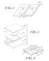
- FIG. 14shows a selective resistance circuit that employs a bubble valve to control electrical current according to the teachings of the present invention.
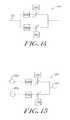
- FIG. 15shows an alternative selective resistance circuit that employs a bubble valve to control electrical current according to the teachings of the present invention.
- FIG. 16shows a particle sorting system that implements a bubble valve of the present invention to produce fluid impulses to sort particles.
- FIGS. 17 a , 17 b and 17 cillustrate the operation of the particle sorting system of FIG. 16 .
- the present inventionprovides an improved bubble valve for controlling fluid flow through a microchannel in a microfluidic system.
- the inventionfurther provides a method of forming the bubble valve.
- the bubble valve of the present inventioncan be applied in numerous microfluidic systems for controlling and switching fluid flows. Examples of suitable applications include, but are not limited to: flow cytometry, column switching, 2-D separations, cell or particle sorting applications on a chip, regulating pressurized fluid flows including on-off switching, regulating electrokinetic fluid flows and electrokinetically induced processes including on-off switching and electrokinetic sample injection and channel to channel switching.
- FIG. 1illustrates a microfluidic system suitable for implementing the illustrative embodiment of the present invention.
- the illustrative microfluidic system 100comprises a substrate 101 having one or more microchannels 21 disposed therein.
- the microchannelstransport fluid through the microfluidic system 100 for processing, handling, and/or performing any suitable operation on a liquid sample.
- microfluidicrefers to a system or device for handling, processing, ejecting and/or analyzing a fluid sample including at least one channel having microscale dimensions.
- channelrefers to a pathway formed in or through a medium that allows for movement of fluids, such as liquids and gases.
- microchannelrefers to a channel preferably formed in a microfluidic system or device having cross-sectional dimensions in the range between about 1.0 ⁇ m and about 500 ⁇ m, preferably between about 25 ⁇ m and about 250 ⁇ m and most preferably between about 50 ⁇ m and about 100 ⁇ m.
- the rangesare intended to include the above-recited values as upper or lower limits.
- the microchannelcan have any selected shape or arrangement, examples of which include a linear or non-linear configuration and a U-shaped configuration.
- the microfluidic system 100may comprise any suitable number of microchannels 21 for transporting fluids through the microfluidic system 100 .
- the microfluidic system 100includes a bubble valve 10 , 10 ′ shown in FIGS. 2-8 c for controlling liquid flow through a microchannel of the system.
- the microchannelis defined by a side wall having any suitable shape enclosing at least a portion of the interior of the channel.
- the bubble valvemay be formed by a gas-filled reservoir positioned adjacent to the microchannel including a meniscus that forms the interface between the reservoir and the microchannel interior. The meniscus may form a portion of the side wall of the microchannel.
- the bubble valveincludes an actuator for modifying the pressure in the reservoir to deflect the meniscus into the channel interior, thereby modifying the cross-sectional area of the microchannel and consequently varying the flow of liquid through the channel.
- the bubble valveis formed by a meniscus in a separate side channel that communicates with and intersects a microchannel through which a liquid to be controlled flows.
- the meniscuscan be located at any location relative to the microchannel through which liquid flows.
- the gas-filled reservoirmay be formed when filling the microchannel having an aperture in a side wall and a reservoir formed adjacent to the aperture.
- An empty microchannelmay be filled with liquid, forming the meniscus in the aperture, which traps the gas that forms the gas bubble and forms a gas pocket in the reservoir adjacent to the meniscus.
- the creation of the gas pocket on fillingprovides a sterile gas bubble and reduces contaminants in the system.
- the air pocketmay be created by introducing a gas to the reservoir after filling of the microchannel.
- FIG. 2shows an exploded view of an embodiment of an illustrative bubble valve 10 of the present invention.
- the microfluidic systemmay be formed by a plurality of stacked layers.
- the illustrative microfluidic system 100includes a first plate 20 in which a groove defining the microchannel 21 is provided.
- a hydrophobic patch 22may be applied to an inner wall of the microchannel 21 .
- a second plate 30 for enclosing the microchannelis bonded to the first plate 20 and includes an aperture 31 .
- a third plate 40is bonded on top of second plate 30 to close and seal the stacked structure.
- the aperture 31 of the intermediate second plate 30defines a void in the system adjacent to the microchannel 21 .
- FIGS. 3 and 4illustrates the assembled bubble valve 10 .
- the stacked first plate 20 , second plate 30 and third plate 40define a closed, gas filled gas reservoir 70 , which can be actuated with a displacement actuator 50 .
- the aperture 31 defining the reservoir 70comprises a main body 31 a and a slot 31 b extending from the main body 31 a .
- the slot 31 b of the aperture 31defines a gap in the side wall of the microchannel 21 that provides access to and communicates with the interior of the microchannel 21 .
- the bubble valve 10operates to control the flow of liquid through the microchannel 21 .
- a meniscusis formed in the aperture 31 , which interfaces with and separates the microchannel interior from the reservoir 70 .
- the meniscusis formed by a liquid filling the microchannel in the slot 31 b .
- the liquid in the slot 31 bis retained in the microchannel by capillary forces.
- the actuator 50deflects the upper wall of the reservoir, defined by plate 40 , which decreases the volume of the reservoir 70 .
- the actuator 50may comprise any suitable device for deflecting the wall, such as an electromagnetic actuator or a piezoelectric element.
- the plate 40may comprises a flexible membrane.
- the decreased volumeconsequently increases the pressure of the reservoir 70 and causes the meniscus 80 to deflect into the channel interior to create a constriction in the channel, thereby impeding fluid flow or pushing fluid away from the meniscus. If a sufficient pressure is applied to the meniscus, the actuator generates and enlarges a bubble in the liquid of the microchannel, which blocks fluid flow.
- the hydrophobic patch 22provides an anchor for the bubble and retains the bubble at a selected location in the microchannel.
- FIG. 5 a - cillustrate the operation of the bubble valve according to the teachings of the invention.
- FIG. 5 ashows the bubble valve in an ‘open’ state.
- the meniscus between the reservoir and the interior of the microchannelis defined by the meniscus 80 , formed by the liquid 60 in the slot 31 b in the second plate 30 .
- the ‘open’ stateliquid flows freely through the microchannel 21 and the valve does not impose any additional flow resistance in the channel.
- the slot 31 bmay be sized and dimensioned to form a “virtual wall” in the microchannel.
- “virtual wall”refers to the meniscus 80 formed by the first liquid 60 in the aperture formed in the side wall of the microchannel 20 , which essentially replaces the removed portion of the side wall without affecting the properties of the microchannel.
- the meniscus surfacecan be, although not required, substantially co-planar with the wall of the microchannel in which the meniscus is formed.
- the word “virtual”is chosen to express the effect that the overall liquid flow through the microchannel 21 of the microfluidic system 100 is not influenced by the virtual wall, i.e.
- the flow of liquid in the microfluidic system having a virtual wallis substantially identical to the flow of liquid through an identical microfluidic system in which no virtual wall is present.
- the meniscusmay be convex or concave, depending on the appropriate system pressure.
- the bubble valve 10switches to a “pinched” state, as shown in FIG. 5 b , to inhibit fluid flow through the channel interior.
- the actuator 50deflects the top of the gas reservoir 70 for a certain fraction, increasing the pressure in the reservoir 70 and forcing the meniscus 80 down into the channel 21 .
- the deflection of the meniscuslocally reduces the cross-section of the channel 21 and introduces an additional flow resistance to the liquid flow.
- the degree of reduction in the liquid flow through the microchannelcorresponds to the amplitude, frequency and duration of the displacement of the meniscus 80 , which are controllable by the actuator 50 .
- any suitable means for varying the pressure within the reservoir 70may be used to deflect the meniscus 80 , thereby regulating fluid flow.
- the bubble valve 10When the actuator is fully actuated, the bubble valve 10 is switched to a closed state, as illustrated in FIG. 5 c .
- the closed statethe meniscus 80 deflects fully to form and introduce a gas bubble 81 into the microchannel 21 .
- the gas bubble 81is retained by the hydrophobic patch 22 formed in the channel wall opposite the slot 31 b .
- the liquid flow in the channelis substantially blocked.
- the bubble valve 10can be brought from the ‘closed’ state of FIG. 5 c via the ‘pinched’ state of FIG. 5 b back to the ‘open’ state of FIG. 5 a.
- the bubble valve 10may be used as a check valve for regulating pressure in the microchannel.
- the pressure in the microchannelexceeds a maximum breaking pressure, the bubble collapses, opening the valve and allowing fluid to flow through the channel, thereby reducing the pressure in the microchannel.
- the breaking pressuredepends on the hydrophobicity of the hydrophobic patch 22 , as well as the geometry of the microchannel.
- the microchannel 21can be locally shaped into a cavity for receiving and anchoring the gas bubble 81 .
- the bubblecan be kept in place during operation, reducing the risk that the gas bubble is carried away with the liquid.
- the actuator 50is integrated in the microfluidic chip 100 .
- an external, reusable actuatormay also be used to control formation of a gas bubble in the microchannel.
- FIG. 6shows an alternative embodiment of a microfluidic system 100 ′ including a bubble valve 10 ′ having an external actuator 90 according to the teachings of the invention.
- the microfluidic system 100 ′includes a first plate 200 including a groove defining the microchannel 210 and a second plate 300 bonded to the first plate 200 for enclosing the microchannel 210 and in which a virtual wall opening 32 is formed.
- the virtual wall opening 32is sized and dimensioned to form a “virtual wall” when the microchannel 210 is filled with a liquid.
- the microfluidic systemfurther includes an external actuator, illustrated as pressurizer 90 , pressed and sealed onto the top of the second plate 300 to form a tight seal.
- the external pressurizer 90defines a sealed pressurizing chamber 92 adjacent to the virtual wall 32 a .
- the pressurizervaries the pressure within the pressurizing chamber 92 to control liquid flow through the microchannel 210 by modifying the position of the virtual wall.
- the pressurizer 90may include a source of pressurized gas (not shown) and a gas inlet 91 to allow a gas pressure to be applied to the virtual wall 32 a in order to move the virtual wall.
- the pressurizermay alternatively include a flexible wall that deflects to vary the volume of the chamber 92 upon activation of an actuator, such as a piezoelectric element or electromagnetic actuator.
- FIG. 8 ashows a cross-section of the bubble valve 10 ′ of FIGS. 6 and 7 in the ‘open’ state.
- a virtual wall 32 adefined by a meniscus 800 , is formed within the virtual wall opening 32 .
- the meniscusessentially replaces the absent portion of the side wall of the microchannel and allows liquid to flow through the channel interior unimpeded and uninfluenced by the virtual wall.
- FIG. 8 bdepicts the ‘pinched’ state of the bubble valve, when the pressurizer 90 is activated.
- activation of the pressurizer 90increases the internal pressure within the pressurizing chamber 92 .
- the increased pressuremoves the meniscus 800 down the channel height and into the microchannel interior, thereby regulating liquid flow.
- the pressurizedcontrols the level of the internal pressure in order to control the amount of deflection of the meniscus and therefore the rate of fluid flow.
- the pressurizer 90applies a large pressure that is sufficient to form and introduce a gas bubble 810 into the channel 210 .
- the hydrophobic patch 220retains the gas bubble 810 in place.
- the liquid flow in the channelis blocked up to a ‘breaking pressure’, which depends on the hydrophobicity of hydrophobic patch 220 .
- a higher hydrophobicityresults in a larger breaking pressure.
- FIG. 9shows an application of a bubble valve 10 for flow regulation in a microchannel 121 according to one embodiment of the invention.
- a pressure differenceis applied over the length of a microchannel 121 .
- a bubble valve 10can be employed to regulate the flow through the microchannel between zero and a maximum flow rate, depending on the applied pressure difference.
- FIG. 10shows a portion of a microfluidic system according to an embodiment of the invention forming a Y-intersection comprising two inlet microchannels 121 a and 121 b and an outlet channel 121 c that combines the fluids flowing through the two inlet microchannels.
- the first microchannel 121 acarries a first liquid and the second microchannel 121 b carries a second liquid.
- the microchannels 121 a and 121 bare each controlled by a corresponding bubble valve, 10 a and 10 b , respectively, for regulating the combined composition and flow rate through the outlet microchannel 121 c .
- the number of inlet channelsis not limited to two, but is presented here merely as an example.
- FIG. 11shows a Y-intersection of a microfluidic system according to another embodiment of the invention.
- the Y-intersectioncomprises an inlet microchannel 221 c and two outlet microchannels 221 a and 221 b for splitting the incoming liquid flow from the inlet microchannel 221 c .
- the flow of each outlet channelis regulated by a corresponding bubble valve 200 a and 200 b , respectively.
- the incoming liquid flow from the inlet microchannel 221 ccan be split between microchannel 221 a and microchannel 221 b in any required ratio.
- the number of inlet channelsis not limited to two, but is presented here merely as an example.
- FIG. 12 a -12 cshows the implementation of an electrophoresis system 110 comprising five bubble valves, 10 a - e of the present invention, arranged with a crossed microchannel configuration.
- Regulation of the bubble valve 10 aregulates the electric current through the associated electrokinetically operated microchannel 115 a .
- the pinching of the liquid in the electrokinetically operated microchannel 115 a by a bubble valvewill result in an increased electrical resistance in the microchannel 115 a .
- the migration of charged species and electro-osmotic flow in the electrokinetically operated microchannel 115 acan be regulated.
- a voltages difference for the injection of sample from a well storing a supply of a sample 125 between the bubble valve 10 a and the crossing point 111 of the microchannels and consecutive separationare provided via wells V+ and V0. Electrodes are placed in the V+ and V0 wells and energized with a constant voltage difference during the operation of the electrophoresis system.
- valves 10 a , 10 b , 10 c and 10 dare substantially in the open position, allowing passage of electrical current up to a required level for injection ( FIG. 12 b shows direction of current/sample), while bubble valve 10 e is closed.
- the valvesare kept in this position long enough for the sample to move from the sample well 125 towards and past the central injection crossing 111 .
- Varying the opening ratio of valves 10 a , 10 b and 10 dcan be adjusted to confine the sample to a narrow flow through the injection cross 111 , as shown in FIG. 12 c (i.e. ‘pinched injection’).
- a plug of sampleis injected and separated in the separation column 115 a (microchannel which runs horizontally in figure) by closing bubble valves 10 a , 10 d and 10 c and opening valves 10 b and 10 e .
- the total voltage differenceis applied longitudinally over the separation channel, resulting in the separation of the constituents in the sample ( FIG. 12 c ).
- FIG. 13 aillustrates another application of the bubble valve of the present invention implemented in a column-column switch 130 for electrokinetically transferring a substance from a first electrokinetically operated microchannel 215 a to a second electrokinetically operated microchannel 215 b .
- the column-column switch 130comprises a bubble valve 10 b of the present invention that connects the first electrokinetically operated microchannel 215 a to the second electrokinetically operated microchannel 215 b .
- Both electrokinetically operated microchannel 215 a and electrokinetically operated microchannel 215 bare connected to corresponding wells well 220 a - d .
- the two electrokinetically operated microchannel 215 a and electrokinetically operated microchannel 215 bare operated independently and the connecting bubble valve 10 b is in the ‘closed’ state whilst bubble valve 10 a and bubble valve 10 c are in the ‘open’ state.
- bubble valve 10 a and bubble valve 10 care switched to the closed state, and the connecting bubble valve 10 b is opened momentarily to allow passage of an amount of substance from the electrokinetically operated microchannel 215 a to the electrokinetically operated microchannel 215 b .
- the amount transferreddepends directly upon the time bubble valve 10 b is opened.
- the connecting bubble valve 10 bis closed and the bubble valve 10 a and bubble valve 10 b are opened again.
- FIG. 13 billustrates the implementation of another column to column switch 130 ′ to exchange liquid from a first column 215 a ′ selectively into a second column 215 b ′.
- the first column and the second columnare each crossed by a transfer column 250 , operated by a first bubble valve 10 a arranged on one end of the transfer column 250 and a second bubble valve 10 b arranged on the opposite end of the transfer column 250 .
- the first one of the bubble valvesis attached to the first column 215 a ′ and is actuated upon transiently by an external actuator for increasing the pressure within the bubble valve reservoir.
- the overall electrical resistance of the electrokinetic circuitcan be switched between four values: infinite (both bubble valves 10 a - b are off), the resistance of fluidic resistor 240 a (bubble valve 10 a on, bubble valve 10 b off), the resistance of fluidic resistor 240 b (bubble valve 10 a off, bubble valve 10 b on) and the parallel resistance of fluidic resistor 24 a - b (both bubble valves 10 a and 10 b on).
- FIG. 15shows an alternative resistance circuit 150 according to another application of the invention, now for the selective application of a voltage.
- the voltage imposed on an outgoing channel 523can be selected.
- Fluidic resistor 245 a and 245 bfunction to limit the electric current in either of the two states to a predetermined value.
- FIG. 16illustrates another application of the bubble valve 10 of the present invention in a particle sorting application, wherein the bubble valve is positioned in a side channel that communicates with a channel through which particles in suspension flow.
- a particle sorter 160comprises a closed channel system of capillary size for sorting particles, such as cells.
- the channel systemcomprises a first supply duct 162 for introducing a stream of particles and a second supply duct 164 for supplying a carrier liquid.
- the first supply duct 162ends in a nozzle, and a stream of particles is introduced into the flow of carrier liquid.
- the first supply duct 162 and the second supply duct 164enter a measurement duct 166 , which branches into a first branch 172 a and a second branch 172 b at a branch point 171 .
- a measurement region 182 ais defined in the measurement duct 166 and is associated with a detector 182 b to sense a predetermined characteristic of particles in the measurement region 182 a .
- Two opposed bubble valves 10 a and 10 bare positioned in communication with the measurement duct 166 and are spaced opposite each other.
- the bubble valves 10 a , 10 bcommunicate with the measurement duct 166 through a pair of opposed side passages 174 a and 174 b , respectively.
- Liquidis allowed to partly fill these side passages 174 a and 174 b to form a meniscus 175 therein.
- An external actuator 176is also provided for actuating the bubble valves 10 a , 10 b , which momentarily causes a flow disturbance in the duct to deflect the flow therein when activated by the actuator 176 .
- a suspension introduced by the first supply duct 162two types of particles can be distinguished, normal particles 180 a and particles of interest 180 b .
- the flow rates in both branches 172 a and 172 bare adjusted so that the stream of particles normally flows through the second branch 172 b .
- the detector 182 bUpon sensing the predetermined characteristic in the particles in the measurement region 182 a , the detector 182 b raises a signal.
- the external actuator 176activates the bubble valves 10 a , 10 b when signaled by the detector 182 b in response to sensing the predetermined characteristic, to create a flow disturbance in the measurement duct 166 between the sideway passages 174 a , 174 b , to deflect the particle having the predetermined characteristic so that it flows down the first branch duct 172 a rather than the second branch duct 172 b .
- the detectorcommunicates with the actuator 176 , so that when the detector 182 b senses a predetermined characteristic in a particle, the actuator activates the first bubble valve 10 a to cause pressure variations in the reservoir 70 of the first bubble valve.
- the activation of the first bubble valvescauses a transient pressure variation in the first side passage 174 a .
- the second side passage 174 b and the second bubble valve 10 babsorb the transient pressure variations in the measurement duct 166 induced via the actuator 176 .
- the reservoir 70 b of the second bubble valve 10 bis a chamber having a resilient wall or contains a compressible fluid such as a gas. The resilient properties allow the flow of liquid from the measurement duct into the second side passage 174 b.
- FIGS. 17 a -17 cillustrate the operation of the particle sorting system 160 of FIG. 16 .
- the detectorraises a signal to activate the actuator.
- the pressure within the reservoir of the first bubble valve 10 ais increased, causing a transient discharge of liquid from the first side passage 174 a as indicated by the arrow.
- the sudden pressure increase caused at this point in the ductcauses liquid to flow into the second side passage 174 b because of the resilient properties of the reservoir of the second bubble valve 10 b .
- This movement of liquid into the second side passage 174 bis indicated with an arrow.
- the flow through the ductis deflected causing the selected particle of interest 178 b located between the first side passage 174 a and the second side passage 174 b to be shifted perpendicular to its flow direction in the normal state.
- the flow resistances to the measurement duct 166 , the first branch 172 a and the second branch 172 bis chosen so that the preferred direction of the flow to and from the first side passage 174 a and the second side passage 174 b has an appreciable component perpendicular to the normal flow through the measurement duct 166 .
- This goalcan for instance be reached by the first branch 172 a and the second branch 172 b so that their resistances to flow is large in comparison with the flow resistances of the first side passage 174 a and the second side passage 174 b.
- FIG. 17 bshows the particle sorting system 160 during the relief of the first bubble valve reservoir when the particle of interest 178 b has left the volume between the first side passage 174 a and the second side passage 174 b .
- the actuator 176is deactivated, causing the pressure inside the reservoir to return to the normal pressure.
- this relief phasethere is a negative pressure difference between the two reservoirs of the bubble valves, causing a liquid flow through the first side passage 174 a and the second side passage 174 b opposite to the liquid flow shown in the previous figure and is indicated by the arrows.
- FIG. 17 cshows the particle sorting system 160 after completion of the switching sequence.
- the pressures inside the reservoirs of the bubble valveshas been equalized so the flow through the measurement duct 166 is normalized.
- the particle of interest 178 bhas been displaced radially, it will flow into the first branch 172 a as was the objective of the switching operation.
- the cross-sectional dimensions of a microchannel including a bubble valvemay be varied locally to affect the pressure within the microchannel interior.
- the microchannelmay be narrowed or widened at certain locations to increase or decrease the capillary forces acting on a fluid in the microchannel interior.
- One of ordinary skill in the artwill be able to determine a suitable cross-sectional dimension to achieve a desired pressure within the microchannel interior.
- the bubble valve of the present inventionmay be implemented in a variety of microfluidic devices used for many applications.
- the bubble valveis implemented in a flow-cytometer based instrument for sorting or physically separating particles of interest from a sample or for measuring selected physical and chemical characteristics of cells or particles in suspension as they travel past a particular site.
- the bubble valvemay also be employed in devices for sequencing or manipulating DNA, medical diagnostic instruments, devices for drug discovery, chemical analysis and so on.
- the present inventionprovides an improved system and method for regulating fluid flow in a microchannel for a variety of applications.
- the bubble valve of the present inventionis easy to operate and control, simple to manufacture and economical.
- the bubble valvedoes not adversely affect the liquid in the microchannel.
- the bubble valveeffectively controls the flow of liquids in microfluidic systems, without heating the fluid and without complex on-chip circuitry.
Landscapes
- Chemical & Material Sciences (AREA)
- Health & Medical Sciences (AREA)
- Dispersion Chemistry (AREA)
- Engineering & Computer Science (AREA)
- General Engineering & Computer Science (AREA)
- Analytical Chemistry (AREA)
- Clinical Laboratory Science (AREA)
- Chemical Kinetics & Catalysis (AREA)
- Hematology (AREA)
- General Health & Medical Sciences (AREA)
- Mechanical Engineering (AREA)
- Micromachines (AREA)
- Automatic Analysis And Handling Materials Therefor (AREA)
Abstract
Description
Claims (9)
Priority Applications (3)
| Application Number | Priority Date | Filing Date | Title |
|---|---|---|---|
| US14/689,508US9943847B2 (en) | 2002-04-17 | 2015-04-17 | Microfluidic system including a bubble valve for regulating fluid flow through a microchannel |
| US15/941,793US10427159B2 (en) | 2002-04-17 | 2018-03-30 | Microfluidic device |
| US16/584,315US11027278B2 (en) | 2002-04-17 | 2019-09-26 | Methods for controlling fluid flow in a microfluidic system |
Applications Claiming Priority (6)
| Application Number | Priority Date | Filing Date | Title |
|---|---|---|---|
| US37325602P | 2002-04-17 | 2002-04-17 | |
| US10/179,586US6877528B2 (en) | 2002-04-17 | 2002-06-24 | Microfluidic system including a bubble valve for regulating fluid flow through a microchannel |
| US11/021,251US7069943B2 (en) | 2002-04-17 | 2004-12-21 | Microfluidic system including a bubble valve for regulating fluid flow through a microchannel |
| US11/433,781US8210209B2 (en) | 2002-04-17 | 2006-05-12 | Microfluidic system including a bubble valve for regulating fluid flow through a microchannel |
| US13/527,331US9011797B2 (en) | 2002-04-17 | 2012-06-19 | Microfluidic system including a bubble valve for regulating fluid flow through a microchannel |
| US14/689,508US9943847B2 (en) | 2002-04-17 | 2015-04-17 | Microfluidic system including a bubble valve for regulating fluid flow through a microchannel |
Related Parent Applications (1)
| Application Number | Title | Priority Date | Filing Date |
|---|---|---|---|
| US13/527,331ContinuationUS9011797B2 (en) | 2002-04-17 | 2012-06-19 | Microfluidic system including a bubble valve for regulating fluid flow through a microchannel |
Related Child Applications (1)
| Application Number | Title | Priority Date | Filing Date |
|---|---|---|---|
| US15/941,793ContinuationUS10427159B2 (en) | 2002-04-17 | 2018-03-30 | Microfluidic device |
Publications (3)
| Publication Number | Publication Date |
|---|---|
| US20160303564A1 US20160303564A1 (en) | 2016-10-20 |
| US20170128938A9 US20170128938A9 (en) | 2017-05-11 |
| US9943847B2true US9943847B2 (en) | 2018-04-17 |
Family
ID=57129519
Family Applications (3)
| Application Number | Title | Priority Date | Filing Date |
|---|---|---|---|
| US14/689,508Expired - LifetimeUS9943847B2 (en) | 2002-04-17 | 2015-04-17 | Microfluidic system including a bubble valve for regulating fluid flow through a microchannel |
| US15/941,793Expired - Fee RelatedUS10427159B2 (en) | 2002-04-17 | 2018-03-30 | Microfluidic device |
| US16/584,315Expired - Fee RelatedUS11027278B2 (en) | 2002-04-17 | 2019-09-26 | Methods for controlling fluid flow in a microfluidic system |
Family Applications After (2)
| Application Number | Title | Priority Date | Filing Date |
|---|---|---|---|
| US15/941,793Expired - Fee RelatedUS10427159B2 (en) | 2002-04-17 | 2018-03-30 | Microfluidic device |
| US16/584,315Expired - Fee RelatedUS11027278B2 (en) | 2002-04-17 | 2019-09-26 | Methods for controlling fluid flow in a microfluidic system |
Country Status (1)
| Country | Link |
|---|---|
| US (3) | US9943847B2 (en) |
Cited By (11)
| Publication number | Priority date | Publication date | Assignee | Title |
|---|---|---|---|---|
| US10427159B2 (en)* | 2002-04-17 | 2019-10-01 | Cytonome/St, Llc | Microfluidic device |
| US10710076B2 (en) | 2018-12-04 | 2020-07-14 | Omniome, Inc. | Mixed-phase fluids for nucleic acid sequencing and other analytical assays |
| US11320361B2 (en) | 2015-02-19 | 2022-05-03 | 1087 Systems, Inc. | Scanning infrared measurement system |
| US11331670B2 (en) | 2018-05-23 | 2022-05-17 | Abs Global, Inc. | Systems and methods for particle focusing in microchannels |
| US11415503B2 (en) | 2013-10-30 | 2022-08-16 | Abs Global, Inc. | Microfluidic system and method with focused energy apparatus |
| US11415936B2 (en) | 2002-07-31 | 2022-08-16 | Abs Global, Inc. | Multiple laminar flow-based particle and cellular separation with laser steering |
| US11512691B2 (en) | 2013-07-16 | 2022-11-29 | Abs Global, Inc. | Microfluidic chip |
| US11628439B2 (en) | 2020-01-13 | 2023-04-18 | Abs Global, Inc. | Single-sheath microfluidic chip |
| US11889830B2 (en) | 2019-04-18 | 2024-02-06 | Abs Global, Inc. | System and process for continuous addition of cryoprotectant |
| US11965816B2 (en) | 2010-11-16 | 2024-04-23 | 1087 Systems, Inc. | Use of vibrational spectroscopy for microfluidic liquid measurement |
| US12135270B2 (en) | 2020-11-23 | 2024-11-05 | Abs Global, Inc. | Modular flow cytometry systems and methods of processing samples |
Families Citing this family (18)
| Publication number | Priority date | Publication date | Assignee | Title |
|---|---|---|---|---|
| US6976590B2 (en) | 2002-06-24 | 2005-12-20 | Cytonome, Inc. | Method and apparatus for sorting particles |
| US9657290B2 (en) | 2012-07-03 | 2017-05-23 | The Board Of Trustees Of The Leland Stanford Junior University | Scalable bio-element analysis |
| CN105008895B (en) | 2012-10-15 | 2019-02-15 | 纳诺赛莱克特生物医药股份有限公司 | System, apparatus and method for particle sorting |
| JP6920997B2 (en) | 2015-02-22 | 2021-08-18 | ザ ボード オブ トラスティーズ オブ ザ レランド スタンフォード ジュニア ユニバーシティー | Microscreening equipment, processes, and products |
| ES2989473T3 (en)* | 2016-11-14 | 2024-11-26 | Orca Biosystems Inc | Apparatus for classifying target particles |
| EP4435113A1 (en) | 2017-05-18 | 2024-09-25 | 10x Genomics, Inc. | Methods and systems for sorting droplets and beads |
| US10544413B2 (en) | 2017-05-18 | 2020-01-28 | 10X Genomics, Inc. | Methods and systems for sorting droplets and beads |
| US11441701B2 (en) | 2017-07-14 | 2022-09-13 | Hewlett-Packard Development Company, L.P. | Microfluidic valve |
| US10610865B2 (en) | 2017-08-22 | 2020-04-07 | 10X Genomics, Inc. | Droplet forming devices and system with differential surface properties |
| WO2019083852A1 (en) | 2017-10-26 | 2019-05-02 | 10X Genomics, Inc. | Microfluidic channel networks for partitioning |
| FR3082440B1 (en)* | 2018-06-14 | 2020-12-11 | Paris Sciences Lettres Quartier Latin | MATERIAL TRANSFER METHOD IN A MICROFLUIDIC OR MILLIFLUIDIC DEVICE |
| CN110605148B (en)* | 2019-10-18 | 2024-07-23 | 广东工业大学 | A microfluidic structure, a microfluidic chip and a method for quantitative heterogeneous reaction |
| TW202128281A (en)* | 2019-12-30 | 2021-08-01 | 美商伊路米納有限公司 | Actuation systems and methods for use with flow cells |
| AU2021219062A1 (en)* | 2020-02-12 | 2022-08-11 | University Of Canterbury | Microfluidic sealing valve and microfluidic circuit |
| KR102442341B1 (en) | 2020-04-14 | 2022-09-14 | 한국과학기술연구원 | Microfluidic device mimicking living microenvironment including diffusion chamber and channel |
| WO2022164672A1 (en)* | 2021-01-27 | 2022-08-04 | Becton, Dickinson And Company | Flow cytometers including fiber optic light collectors, and methods of use thereof |
| CN113101846B (en)* | 2021-05-10 | 2022-03-29 | 浙江师范大学 | Active-passive combined piezoelectric gas micro mixer |
| WO2025163588A1 (en)* | 2024-02-01 | 2025-08-07 | University Of Canterbury | Microfluidic devices, systems and methods |
Citations (154)
| Publication number | Priority date | Publication date | Assignee | Title |
|---|---|---|---|---|
| US2850940A (en) | 1955-04-28 | 1958-09-09 | Perkin Elmer Corp | Device to measure refractive index gradient |
| US3289687A (en) | 1964-02-13 | 1966-12-06 | J C Dunaway | Actuator for pure fluid amplifier |
| US3370538A (en) | 1966-02-11 | 1968-02-27 | E W Hines And Associates | Fluid pumps energized by magnetostrictive action |
| US3508655A (en) | 1967-02-03 | 1970-04-28 | Ibm | Cell extraction and collection apparatus |
| US3508654A (en) | 1966-08-31 | 1970-04-28 | Ibm | Particle separation apparatus |
| US3560754A (en) | 1965-11-17 | 1971-02-02 | Ibm | Photoelectric particle separator using time delay |
| US3791517A (en) | 1973-03-05 | 1974-02-12 | Bio Physics Systems Inc | Digital fluidic amplifier particle sorter |
| JPS4946274A (en) | 1972-09-12 | 1974-05-02 | ||
| US3827555A (en) | 1973-03-05 | 1974-08-06 | Bio Physics Systems Inc | Particle sorter with segregation indicator |
| US3906415A (en) | 1974-06-14 | 1975-09-16 | Massachusetts Inst Technology | Apparatus wherein a segmented fluid stream performs electrical switching functions and the like |
| US3984307A (en) | 1973-03-05 | 1976-10-05 | Bio/Physics Systems, Inc. | Combined particle sorter and segregation indicator |
| US3984621A (en) | 1975-09-15 | 1976-10-05 | Merritt Foods Company | Electrically wired floor construction |
| US4050851A (en) | 1975-11-10 | 1977-09-27 | The Nash Engineering Company | Liquid ring pumps and compressors using a ferrofluidic ring liquid |
| US4147621A (en) | 1977-06-28 | 1979-04-03 | University Of Utah | Method and apparatus for flow field-flow fractionation |
| US4153855A (en) | 1977-12-16 | 1979-05-08 | The United States Of America As Represented By The Secretary Of The Army | Method of making a plate having a pattern of microchannels |
| US4175662A (en) | 1977-04-12 | 1979-11-27 | Tibor Zold | Method and device for sorting particles suspended in an electrolyte |
| US4318483A (en) | 1979-08-20 | 1982-03-09 | Ortho Diagnostics, Inc. | Automatic relative droplet charging time delay system for an electrostatic particle sorting system using a relatively moveable stream surface sensing system |
| US4361400A (en) | 1980-11-26 | 1982-11-30 | The United States Of America As Represented By The United States Department Of Energy | Fluidic assembly for an ultra-high-speed chromosome flow sorter |
| US4365719A (en) | 1981-07-06 | 1982-12-28 | Leonard Kelly | Radiometric ore sorting method and apparatus |
| US4426451A (en) | 1981-01-28 | 1984-01-17 | Eastman Kodak Company | Multi-zoned reaction vessel having pressure-actuatable control means between zones |
| US4445696A (en) | 1983-02-22 | 1984-05-01 | Ferrofluidics Corporation | Nonbursting magnetic liquid seals for high vacuum applications |
| GB2140128A (en) | 1983-05-19 | 1984-11-21 | Emi Ltd | Gas valve |
| US4526276A (en) | 1983-04-28 | 1985-07-02 | Becton, Dickinson And Company | Apparatus and method for sorting particles by gas actuation |
| US4554427A (en) | 1983-12-19 | 1985-11-19 | Westinghouse Electric Corp. | Molded case circuit breaker with movable lower electrical contact |
| US4572664A (en) | 1982-04-07 | 1986-02-25 | Forsogsanleg Riso | Method of measuring velocity gradients in a flowing medium and apparatus for carrying out the method |
| US4579173A (en) | 1983-09-30 | 1986-04-01 | Exxon Research And Engineering Co. | Magnetized drive fluids |
| US4581624A (en) | 1984-03-01 | 1986-04-08 | Allied Corporation | Microminiature semiconductor valve |
| EP0177718A2 (en) | 1984-09-11 | 1986-04-16 | Partec AG | Method and device for sorting microscopic particles |
| US4636149A (en) | 1985-05-13 | 1987-01-13 | Cordis Corporation | Differential thermal expansion driven pump |
| US4676274A (en)* | 1985-02-28 | 1987-06-30 | Brown James F | Capillary flow control |
| JPS63259466A (en) | 1987-04-16 | 1988-10-26 | Hitachi Ltd | cell analyzer |
| US4808079A (en) | 1987-06-08 | 1989-02-28 | Crowley Christopher J | Magnetic pump for ferrofluids |
| JPH01170853A (en) | 1987-12-25 | 1989-07-05 | Hitachi Ltd | Cell screening device |
| US4908112A (en) | 1988-06-16 | 1990-03-13 | E. I. Du Pont De Nemours & Co. | Silicon semiconductor wafer for analyzing micronic biological samples |
| US4936465A (en) | 1987-12-07 | 1990-06-26 | Zoeld Tibor | Method and apparatus for fast, reliable, and environmentally safe dispensing of fluids, gases and individual particles of a suspension through pressure control at well defined parts of a closed flow-through system |
| US4939081A (en) | 1987-05-27 | 1990-07-03 | The Netherlands Cancer Institute | Cell-separation |
| GB2229649A (en) | 1989-04-01 | 1990-10-03 | Magyar Tudomanyos Akademia | Apparatus for the realization of biocatalytic process with solid phase biocatalyst |
| US5005639A (en) | 1988-03-24 | 1991-04-09 | The United States Of America As Represented By The Secretary Of The Air Force | Ferrofluid piston pump for use with heat pipes or the like |
| US5030002A (en) | 1989-08-11 | 1991-07-09 | Becton, Dickinson And Company | Method and apparatus for sorting particles with a moving catcher tube |
| WO1991014505A1 (en) | 1988-09-30 | 1991-10-03 | Occam Marine Technologies Ltd. | Low speed particle concentrator |
| WO1991015750A1 (en) | 1990-04-09 | 1991-10-17 | Carri-Med Limited | Microfabricated device for biological cell sorting |
| US5065978A (en) | 1988-04-27 | 1991-11-19 | Dragerwerk Aktiengesellschaft | Valve arrangement of microstructured components |
| US5092972A (en) | 1990-07-12 | 1992-03-03 | Board Of Supervisors Of Louisiana State University And Agricultural And Mechanical College | Field-effect electroosmosis |
| US5101978A (en) | 1989-11-27 | 1992-04-07 | The United States Of America As Represented By The Secretary Of The Army | Fluidic sorting device for two or more materials suspended in a fluid |
| US5193688A (en) | 1989-12-08 | 1993-03-16 | University Of Utah | Method and apparatus for hydrodynamic relaxation and sample concentration NIN field-flow fraction using permeable wall elements |
| US5213479A (en) | 1992-04-09 | 1993-05-25 | The Nash Engineering Company | Liquid ring pumps with improved housing shapes |
| US5265327A (en) | 1991-09-13 | 1993-11-30 | Faris Sadeg M | Microchannel plate technology |
| US5275787A (en) | 1989-10-04 | 1994-01-04 | Canon Kabushiki Kaisha | Apparatus for separating or measuring particles to be examined in a sample fluid |
| US5395588A (en) | 1992-12-14 | 1995-03-07 | Becton Dickinson And Company | Control of flow cytometer having vacuum fluidics |
| US5486335A (en) | 1992-05-01 | 1996-01-23 | Trustees Of The University Of Pennsylvania | Analysis based on flow restriction |
| US5541072A (en) | 1994-04-18 | 1996-07-30 | Immunivest Corporation | Method for magnetic separation featuring magnetic particles in a multi-phase system |
| EP0745682A1 (en) | 1995-06-02 | 1996-12-04 | Bayer Ag | Sorting apparatus for biological cells and viruses |
| US5622831A (en) | 1990-09-26 | 1997-04-22 | Immunivest Corporation | Methods and devices for manipulation of magnetically collected material |
| JPH09141124A (en) | 1995-11-17 | 1997-06-03 | Yazaki Corp | Micro-substance separation device in liquid |
| US5637496A (en) | 1993-07-02 | 1997-06-10 | B. Braun Biotech International Mbh | Device and method for conveying and separating a suspension with biological cells or micro-organisms |
| US5699157A (en) | 1996-07-16 | 1997-12-16 | Caliper Technologies Corp. | Fourier detection of species migrating in a microchannel |
| WO1998007069A1 (en) | 1996-08-12 | 1998-02-19 | The Regents Of The University Of Michigan | Polymer-based micromachining technology for microfluidic devices |
| WO1998010267A1 (en) | 1996-09-04 | 1998-03-12 | Technical University Of Denmark | A micro flow system for particle separation and analysis |
| US5777649A (en) | 1992-10-09 | 1998-07-07 | Canon Kabushiki Kaisha | Ink jet printing head with buffering chamber wall having gas transmitting property and printing apparatus using same |
| US5783446A (en) | 1996-03-04 | 1998-07-21 | Biocircuits Corporation | Particle assay using fluid velocity gradients |
| US5789045A (en) | 1994-04-15 | 1998-08-04 | The United States Of America As Represented By The Secretary Of The Air Force | Microtubes devices based on surface tension and wettability |
| US5795727A (en) | 1991-08-28 | 1998-08-18 | Becton Dickinson And Company | Gravitational attractor engine for adaptively autoclustering n-dimensional datastreams |
| WO1998052691A1 (en) | 1997-05-16 | 1998-11-26 | Alberta Research Council | Microfluidic system and methods of use |
| US5876187A (en) | 1995-03-09 | 1999-03-02 | University Of Washington | Micropumps with fixed valves |
| US5885470A (en) | 1997-04-14 | 1999-03-23 | Caliper Technologies Corporation | Controlled fluid transport in microfabricated polymeric substrates |
| WO1999023471A1 (en) | 1997-10-31 | 1999-05-14 | Giammaria Sitar | Device and method for the separation of human or animal cells of different densities from cellular dispersions which contain them |
| JPH11508182A (en) | 1995-06-16 | 1999-07-21 | ザ ユニバーシティ オブ ワシントン | Microfabricated differential extraction device and method |
| US5976336A (en) | 1997-04-25 | 1999-11-02 | Caliper Technologies Corp. | Microfluidic devices incorporating improved channel geometries |
| US5979664A (en) | 1995-10-31 | 1999-11-09 | Institute Of Paper Science And Technology, Inc. | Methods and apparatus for acoustic fiber fractionation |
| US5988522A (en) | 1995-06-12 | 1999-11-23 | Georgia Tech Research Corporation | Synthetic jet actuators for modifiying the direction of fluid flows |
| US5998212A (en) | 1991-04-05 | 1999-12-07 | University Of Texas Medical Branch At Galveston | Method for flexibly sorting particles |
| US6033191A (en)* | 1997-05-16 | 2000-03-07 | Institut Fur Mikrotechnik Mainz Gmbh | Micromembrane pump |
| US6046056A (en) | 1996-06-28 | 2000-04-04 | Caliper Technologies Corporation | High throughput screening assay systems in microscale fluidic devices |
| US6048734A (en) | 1995-09-15 | 2000-04-11 | The Regents Of The University Of Michigan | Thermal microvalves in a fluid flow method |
| US6048328A (en) | 1998-02-02 | 2000-04-11 | Medtronic, Inc. | Implantable drug infusion device having an improved valve |
| US6057111A (en) | 1996-11-13 | 2000-05-02 | Quark Biotech, Inc. | Gene identification method |
| US6062681A (en) | 1998-07-14 | 2000-05-16 | Hewlett-Packard Company | Bubble valve and bubble valve-based pressure regulator |
| US6102530A (en) | 1998-01-23 | 2000-08-15 | Kim; Chang-Jin | Apparatus and method for using bubble as virtual valve in microinjector to eject fluid |
| US6120666A (en) | 1996-09-26 | 2000-09-19 | Ut-Battelle, Llc | Microfabricated device and method for multiplexed electrokinetic focusing of fluid streams and a transport cytometry method using same |
| US6145247A (en) | 1996-06-27 | 2000-11-14 | Weyerhaeuser Company | Fluid switch |
| WO2000070080A1 (en) | 1999-05-17 | 2000-11-23 | Caliper Technologies Corp. | Focusing of microparticles in microfluidic systems |
| US6152181A (en) | 1992-11-16 | 2000-11-28 | The United States Of America As Represented By The Secretary Of The Air Force | Microdevices based on surface tension and wettability that function as sensors, actuators, and other devices |
| EP1065378A2 (en) | 1999-06-28 | 2001-01-03 | California Institute of Technology | Microfabricated elastomeric valve and pump systems |
| US6196525B1 (en) | 1996-05-13 | 2001-03-06 | Universidad De Sevilla | Device and method for fluid aeration via gas forced through a liquid within an orifice of a pressure chamber |
| US6203291B1 (en) | 1993-02-23 | 2001-03-20 | Erik Stemme | Displacement pump of the diaphragm type having fixed geometry flow control means |
| US6214556B1 (en) | 1997-11-27 | 2001-04-10 | Epigenomics Ag | Method for producing complex DNA methylation fingerprints |
| US6221654B1 (en) | 1996-09-25 | 2001-04-24 | California Institute Of Technology | Method and apparatus for analysis and sorting of polynucleotides based on size |
| US6273553B1 (en) | 1998-01-23 | 2001-08-14 | Chang-Jin Kim | Apparatus for using bubbles as virtual valve in microinjector to eject fluid |
| US6280967B1 (en) | 1996-08-02 | 2001-08-28 | Axiom Biotechnologies, Inc. | Cell flow apparatus and method for real-time of cellular responses |
| US6318970B1 (en) | 1998-03-12 | 2001-11-20 | Micralyne Inc. | Fluidic devices |
| US20020005354A1 (en) | 1997-09-23 | 2002-01-17 | California Institute Of Technology | Microfabricated cell sorter |
| WO2002010713A2 (en) | 2000-08-02 | 2002-02-07 | Honeywell International Inc. | Portable flow cytometer |
| US6360775B1 (en) | 1998-12-23 | 2002-03-26 | Agilent Technologies, Inc. | Capillary fluid switch with asymmetric bubble chamber |
| US20020058332A1 (en) | 2000-09-15 | 2002-05-16 | California Institute Of Technology | Microfabricated crossflow devices and methods |
| WO2002044689A2 (en) | 2000-11-28 | 2002-06-06 | The Regents Of The University Of California | Storing microparticles in optical switch which is transported by micro-fluidic device |
| US20020093641A1 (en) | 2000-08-25 | 2002-07-18 | Ortyn William E. | Measuring the velocity of small moving objects such as cells |
| US6431212B1 (en) | 2000-05-24 | 2002-08-13 | Jon W. Hayenga | Valve for use in microfluidic structures |
| US6455280B1 (en) | 1998-12-22 | 2002-09-24 | Genset S.A. | Methods and compositions for inhibiting neoplastic cell growth |
| US6454862B1 (en) | 1998-11-05 | 2002-09-24 | Matsushita Electric Industrial Co., Ltd. | Fine-particle classification apparatus and functional material production apparatus |
| US20020166585A1 (en) | 2000-11-06 | 2002-11-14 | Nanostream, Inc. | Microfluidic regulating device |
| US6481453B1 (en) | 2000-04-14 | 2002-11-19 | Nanostream, Inc. | Microfluidic branch metering systems and methods |
| US6482652B2 (en) | 2000-03-23 | 2002-11-19 | The Board Of Trustees Of The Leland Stanford Junior University | Biological particle sorter |
| US20030027225A1 (en) | 2001-07-13 | 2003-02-06 | Caliper Technologies Corp. | Microfluidic devices and systems for separating components of a mixture |
| US6524790B1 (en) | 1997-06-09 | 2003-02-25 | Caliper Technologies Corp. | Apparatus and methods for correcting for variable velocity in microfluidic systems |
| US6540895B1 (en) | 1997-09-23 | 2003-04-01 | California Institute Of Technology | Microfabricated cell sorter for chemical and biological materials |
| US6561224B1 (en) | 2002-02-14 | 2003-05-13 | Abbott Laboratories | Microfluidic valve and system therefor |
| US6592821B1 (en) | 1999-05-17 | 2003-07-15 | Caliper Technologies Corp. | Focusing of microparticles in microfluidic systems |
| US6629820B2 (en) | 2001-06-26 | 2003-10-07 | Micralyne Inc. | Microfluidic flow control device |
| WO2003089158A1 (en) | 2002-04-17 | 2003-10-30 | Cytonome, Inc. | Method and apparatus for sorting particles |
| US6657730B2 (en) | 2001-01-04 | 2003-12-02 | Tilman Pfau | Interferometer with angled beam entry |
| US20040037739A1 (en) | 2001-03-09 | 2004-02-26 | Mcneely Michael | Method and system for microfluidic interfacing to arrays |
| US6739576B2 (en) | 2001-12-20 | 2004-05-25 | Nanostream, Inc. | Microfluidic flow control device with floating element |
| US20040180426A1 (en) | 2000-07-10 | 2004-09-16 | Maher Michael P. | High throughput method and system for screening candidate compounds for activity against target ion channels |
| US6803194B1 (en) | 1998-02-13 | 2004-10-12 | Hk Pharmaceuticals, Inc. | Use of ribozymes for functionating genes |
| US6802342B2 (en) | 2001-04-06 | 2004-10-12 | Fluidigm Corporation | Microfabricated fluidic circuit elements and applications |
| US6808075B2 (en) | 2002-04-17 | 2004-10-26 | Cytonome, Inc. | Method and apparatus for sorting particles |
| US6821484B1 (en) | 1998-09-02 | 2004-11-23 | Accip Biotech Aps | Apparatus for isolation of particles, preferably cell clusters |
| US20040233424A1 (en) | 2003-05-21 | 2004-11-25 | National Cheng Kung University | Chip-based microfluidic particle detector with three dimensional focusing mechanisms |
| US6877528B2 (en) | 2002-04-17 | 2005-04-12 | Cytonome, Inc. | Microfluidic system including a bubble valve for regulating fluid flow through a microchannel |
| US6976590B2 (en) | 2002-06-24 | 2005-12-20 | Cytonome, Inc. | Method and apparatus for sorting particles |
| US7024281B1 (en) | 2000-12-11 | 2006-04-04 | Callper Life Sciences, Inc. | Software for the controlled sampling of arrayed materials |
| US7075652B1 (en) | 2004-11-12 | 2006-07-11 | Ibet, Inc. | Apparatus and method for measuring temperature dependent properties of liquid |
| US20060170912A1 (en) | 2005-02-01 | 2006-08-03 | Daniel Mueth | Method and apparatus for sorting cells |
| US20060177348A1 (en) | 2005-02-08 | 2006-08-10 | Kenji Yasuda | Cell sorter chip having gel electrodes |
| US7157274B2 (en) | 2002-06-24 | 2007-01-02 | Cytonome, Inc. | Method and apparatus for sorting particles |
| US7157275B2 (en) | 2003-08-15 | 2007-01-02 | Becton, Dickinson And Company | Peptides for enhanced cell attachment and growth |
| US20070065808A1 (en) | 2002-04-17 | 2007-03-22 | Cytonome, Inc. | Method and apparatus for sorting particles |
| US7220594B2 (en) | 2002-07-08 | 2007-05-22 | Innovative Micro Technology | Method and apparatus for sorting particles with a MEMS device |
| US7258774B2 (en) | 2000-10-03 | 2007-08-21 | California Institute Of Technology | Microfluidic devices and methods of use |
| US7303727B1 (en) | 2002-03-06 | 2007-12-04 | Caliper Life Sciences, Inc | Microfluidic sample delivery devices, systems, and methods |
| US20080070311A1 (en) | 2006-09-19 | 2008-03-20 | Vanderbilt University | Microfluidic flow cytometer and applications of same |
| US7355699B2 (en) | 2003-08-14 | 2008-04-08 | Cytonome, Inc. | Optical detector for a particle sorting system |
| US7389879B2 (en) | 2004-01-21 | 2008-06-24 | Hewlett-Packard Development Company, L.P. | Sorting particles |
| US20080213821A1 (en) | 2004-05-06 | 2008-09-04 | Nanyang Technological University | Microfluidic Cell Sorter System |
| US7452725B2 (en) | 2002-01-10 | 2008-11-18 | Board Of Regents, The University Of Texas System | Flow sorting system and methods regarding same |
| US7612355B2 (en) | 2004-04-12 | 2009-11-03 | The Regents Of The University Of California | Optoelectronic tweezers for microparticle and cell manipulation |
| US20090283452A1 (en) | 2006-11-30 | 2009-11-19 | Palo Alto Research Center Incorporated | Method and apparatus for splitting fluid flow in a membraneless particle separation system |
| US7820427B2 (en) | 2001-11-30 | 2010-10-26 | Fluidigm Corporation | Microfluidic device and methods of using same |
| US7863035B2 (en) | 2007-02-15 | 2011-01-04 | Osmetech Technology Inc. | Fluidics devices |
| US20110030808A1 (en) | 2009-08-08 | 2011-02-10 | The Regents Of The University Of California | Pulsed laser triggered high speed microfluidic switch and applications in fluorescent activated cell sorting |
| US8123044B2 (en) | 2006-05-05 | 2012-02-28 | Cytonome/St, Llc | Actuation of parallel microfluidic arrays |
| US8252604B2 (en) | 2004-10-01 | 2012-08-28 | Rudolf Rigler | Selection of particles in laminar flow |
| US20120258488A1 (en) | 2011-04-11 | 2012-10-11 | The Regents Of The University Of California | Systems and Methods for Electrophysiological Activated Cell Sorting and Cytometry |
| US20130083315A1 (en) | 2009-03-10 | 2013-04-04 | Yu-hwa Lo | Fluidic flow cytometry devices and methods |
| US8609039B2 (en) | 2006-01-19 | 2013-12-17 | Rheonix, Inc. | Microfluidic systems and control methods |
| US8623294B2 (en) | 2008-03-24 | 2014-01-07 | Nec Corporation | Flow passage control mechanism for microchip |
| US8691164B2 (en) | 2007-04-20 | 2014-04-08 | Celula, Inc. | Cell sorting system and methods |
| US8723140B2 (en) | 2011-08-09 | 2014-05-13 | Palo Alto Research Center Incorporated | Particle analyzer with spatial modulation and long lifetime bioprobes |
| US8844571B2 (en) | 2009-07-23 | 2014-09-30 | Airbus Operations Gmbh | Fluid actuator for producing a pulsed outlet flow in the flow around an aerodynamic body, and discharge device and aerodynamic body equipped therewith |
| US20140339445A1 (en) | 2013-03-14 | 2014-11-20 | Cytonome/St, Llc | Micro-lens systems for particle processing systems |
| US8895311B1 (en) | 2001-03-28 | 2014-11-25 | Handylab, Inc. | Methods and systems for control of general purpose microfluidic devices |
| US9074978B2 (en) | 2011-07-12 | 2015-07-07 | The Regents Of The University Of California | Optical space-time coding technique in microfluidic devices |
| US9149806B2 (en) | 2012-01-10 | 2015-10-06 | Biopico Systems Inc | Microfluidic devices and methods for cell sorting, cell culture and cells based diagnostics and therapeutics |
| US9194786B2 (en) | 2012-08-01 | 2015-11-24 | Owl biomedical, Inc. | Particle manipulation system with cytometric capability |
Family Cites Families (183)
| Publication number | Priority date | Publication date | Assignee | Title |
|---|---|---|---|---|
| US350864A (en) | 1886-10-12 | Umax butler | ||
| US2015522A (en) | 1931-12-16 | 1935-09-24 | Alfred O Hoffman | Riffle trough |
| US2646882A (en) | 1950-08-02 | 1953-07-28 | Jr Hildreth Frost | Flotation machine |
| US2787453A (en) | 1953-11-30 | 1957-04-02 | Exxon Research Engineering Co | Fractionating tower utilizing directional upflow means in conjunction with slanted trays |
| US2923410A (en) | 1957-04-29 | 1960-02-02 | Tschmelitsch Florian | Portable flexible sluice box |
| US3362421A (en) | 1963-05-28 | 1968-01-09 | Ibm | Bounded free jet fluid amplifier with turbulent attachment |
| US3380584A (en) | 1965-06-04 | 1968-04-30 | Atomic Energy Commission Usa | Particle separator |
| US3506654A (en) | 1966-09-15 | 1970-04-14 | Syntex Corp | Benzylidene derivatives of chromene,thiochromene,quinoline,and n-alkyl quinoline and corresponding benzyl tertiary carbinol intermediates |
| US3785390A (en) | 1967-03-09 | 1974-01-15 | Powers Regulator Co | Pure fluid amplifier |
| US3495253A (en) | 1967-06-26 | 1970-02-10 | George B Richards | Planar fluid amplifier |
| US3574309A (en) | 1968-06-28 | 1971-04-13 | Foxboro Co | Chambered fluidic amplifier |
| US4004150A (en) | 1975-05-01 | 1977-01-18 | Samuel Natelson | Analytical multiple component readout system |
| US4148585A (en) | 1977-02-11 | 1979-04-10 | The United States Of America As Represented By The Department Of Health, Education & Welfare | Three dimensional laser Doppler velocimeter |
| US4195811A (en) | 1977-08-22 | 1980-04-01 | EMX Controls Inc. | Electronic valve control means |
| CA1127227A (en) | 1977-10-03 | 1982-07-06 | Ichiro Endo | Liquid jet recording process and apparatus therefor |
| US4284499A (en) | 1978-04-19 | 1981-08-18 | Occidental Research Corporation | Apparatus for the float concentration of ore |
| US4279345A (en) | 1979-08-03 | 1981-07-21 | Allred John C | High speed particle sorter using a field emission electrode |
| JPS57132038A (en) | 1981-02-10 | 1982-08-16 | Olympus Optical Co Ltd | Photometric device |
| US4344844A (en) | 1981-03-17 | 1982-08-17 | Townley J O | Inclined static deoiler and conditioner for treating ore |
| US4498782A (en) | 1981-05-29 | 1985-02-12 | Science Research Center, Inc. | Assembly for determining light transmissiveness of a fluid |
| JPS5857560A (en) | 1981-09-30 | 1983-04-05 | Fuji Heavy Ind Ltd | Air breather mechanism for oil seal |
| GB2116740B (en) | 1982-02-27 | 1985-08-29 | Bergstroem Arne | Objectives comprising pinhole aperture and image intensifier |
| US4541429A (en) | 1982-05-10 | 1985-09-17 | Prosl Frank R | Implantable magnetically-actuated valve |
| US4478077A (en) | 1982-09-30 | 1984-10-23 | Honeywell Inc. | Flow sensor |
| US4478076A (en) | 1982-09-30 | 1984-10-23 | Honeywell Inc. | Flow sensor |
| US4501144A (en) | 1982-09-30 | 1985-02-26 | Honeywell Inc. | Flow sensor |
| US4651564A (en) | 1982-09-30 | 1987-03-24 | Honeywell Inc. | Semiconductor device |
| JPS60153023A (en) | 1984-01-23 | 1985-08-12 | Toshiba Corp | Beam splitter device for high power laser |
| US4797696A (en) | 1985-07-24 | 1989-01-10 | Ateq Corporation | Beam splitting apparatus |
| US4963498A (en) | 1985-08-05 | 1990-10-16 | Biotrack | Capillary flow device |
| NZ216327A (en) | 1986-05-28 | 1989-04-26 | Lindsay Guy Herron | Hollow, perforated riffle bar and apparatus using a set of bars |
| DE3851458T2 (en) | 1987-04-08 | 1995-02-09 | Hitachi Ltd | Device with a vaginal flow cell. |
| US5053344A (en) | 1987-08-04 | 1991-10-01 | Cleveland Clinic Foundation | Magnetic field separation and analysis system |
| US5040890A (en) | 1987-11-25 | 1991-08-20 | Becton, Dickinson And Company | Sheathed particle flow controlled by differential pressure |
| DE3831630A1 (en) | 1988-09-17 | 1990-03-22 | Ulrich M Landwehr | METHOD AND DEVICE FOR DETERMINING THE DIMENSIONS OF AN OBJECT BY PHOTOGRAPHIC WAY |
| US4954715A (en) | 1989-06-26 | 1990-09-04 | Zoeld Tibor | Method and apparatus for an optimized multiparameter flow-through particle and cell analyzer |
| US5238223A (en) | 1989-08-11 | 1993-08-24 | Robert Bosch Gmbh | Method of making a microvalve |
| US5244537A (en) | 1989-12-27 | 1993-09-14 | Honeywell, Inc. | Fabrication of an electronic microvalve apparatus |
| KR910012538A (en) | 1989-12-27 | 1991-08-08 | 야마무라 가쯔미 | Micro pump and its manufacturing method |
| US5082242A (en) | 1989-12-27 | 1992-01-21 | Ulrich Bonne | Electronic microvalve apparatus and fabrication |
| US5050429A (en) | 1990-02-22 | 1991-09-24 | Yamatake-Honeywell Co., Ltd. | Microbridge flow sensor |
| AU642285B2 (en) | 1990-07-10 | 1993-10-14 | Debiotech S.A. | Valve and micropump incorporating said valve |
| CA2069894C (en) | 1990-08-31 | 2001-04-24 | Harald T. G. Van Lintel | Valve equipped with a position detector and a micropump incorporating said valve |
| US5204884A (en) | 1991-03-18 | 1993-04-20 | University Of Rochester | System for high-speed measurement and sorting of particles |
| FI86340C (en) | 1990-10-31 | 1992-08-10 | Labsystems Oy | FOERFARANDE FOER LEDNING AV LJUS. |
| US5108623A (en) | 1990-11-19 | 1992-04-28 | Gould Inc. | Moving web filter assembly |
| US5176358A (en) | 1991-08-08 | 1993-01-05 | Honeywell Inc. | Microstructure gas valve control |
| JPH05157684A (en) | 1991-12-02 | 1993-06-25 | Seikagaku Kogyo Co Ltd | Absorptionmeter |
| US5726026A (en) | 1992-05-01 | 1998-03-10 | Trustees Of The University Of Pennsylvania | Mesoscale sample preparation device and systems for determination and processing of analytes |
| US5498392A (en) | 1992-05-01 | 1996-03-12 | Trustees Of The University Of Pennsylvania | Mesoscale polynucleotide amplification device and method |
| US5466572A (en) | 1992-09-03 | 1995-11-14 | Systemix, Inc. | High speed flow cytometric separation of viable cells |
| US5489506A (en) | 1992-10-26 | 1996-02-06 | Biolife Systems, Inc. | Dielectrophoretic cell stream sorter |
| US5441597A (en) | 1992-12-01 | 1995-08-15 | Honeywell Inc. | Microstructure gas valve control forming method |
| SE501713C2 (en) | 1993-09-06 | 1995-05-02 | Pharmacia Biosensor Ab | Diaphragm-type valve, especially for liquid handling blocks with micro-flow channels |
| US5483469A (en) | 1993-08-02 | 1996-01-09 | The Regents Of The University Of California | Multiple sort flow cytometer |
| US5464581A (en) | 1993-08-02 | 1995-11-07 | The Regents Of The University Of California | Flow cytometer |
| AU680671B2 (en) | 1993-09-16 | 1997-08-07 | Owens-Brockway Glass Container Inc. | Inspection of translucent containers |
| JP2948069B2 (en) | 1993-09-20 | 1999-09-13 | 株式会社日立製作所 | Chemical analyzer |
| US5544756A (en) | 1994-03-14 | 1996-08-13 | Peter Abt | Dynamic mining system comprsing hydrated multiple recovery sites and related methods |
| GB9406551D0 (en) | 1994-03-31 | 1994-05-25 | Hjelm Nils M | Chromatography system and methodology |
| JPH07286953A (en) | 1994-04-19 | 1995-10-31 | Toa Medical Electronics Co Ltd | Imaging flow sight meter |
| US5632935A (en) | 1994-04-28 | 1997-05-27 | Koch Engineering Company, Inc. | Vapor-liquid contact tray and downcomer assembly and method employing same |
| US6001229A (en) | 1994-08-01 | 1999-12-14 | Lockheed Martin Energy Systems, Inc. | Apparatus and method for performing microfluidic manipulations for chemical analysis |
| EP0786078B1 (en) | 1994-10-14 | 2004-01-07 | University of Washington | System and method for high speed flow cytometer droplet formation |
| US5602039A (en) | 1994-10-14 | 1997-02-11 | The University Of Washington | Flow cytometer jet monitor system |
| JP3220158B2 (en) | 1994-11-14 | 2001-10-22 | トラスティーズ・オブ・ザ・ユニバーシティ・オブ・ペンシルベニア | Mesoscale sample pretreatment devices and systems for analyte determination and processing |
| US5608519A (en) | 1995-03-20 | 1997-03-04 | Gourley; Paul L. | Laser apparatus and method for microscopic and spectroscopic analysis and processing of biological cells |
| US5716852A (en) | 1996-03-29 | 1998-02-10 | University Of Washington | Microfabricated diffusion-based chemical sensor |
| EP0871539B1 (en) | 1995-06-16 | 2002-02-20 | University of Washington | Tangential flow planar microfabricated fluid filter |
| US5856174A (en) | 1995-06-29 | 1999-01-05 | Affymetrix, Inc. | Integrated nucleic acid diagnostic device |
| JP3515646B2 (en) | 1995-09-18 | 2004-04-05 | 大塚電子株式会社 | Multi-capillary electrophoresis device |
| US5726751A (en) | 1995-09-27 | 1998-03-10 | University Of Washington | Silicon microchannel optical flow cytometer |
| US6068751A (en) | 1995-12-18 | 2000-05-30 | Neukermans; Armand P. | Microfluidic valve and integrated microfluidic system |
| JP3308441B2 (en) | 1995-12-19 | 2002-07-29 | シスメックス株式会社 | Urine particle analyzer |
| US5863502A (en) | 1996-01-24 | 1999-01-26 | Sarnoff Corporation | Parallel reaction cassette and associated devices |
| US5851488A (en) | 1996-02-29 | 1998-12-22 | Biocircuits Corporation | Apparatus for automatic electro-optical chemical assay determination |
| US5948684A (en) | 1997-03-31 | 1999-09-07 | University Of Washington | Simultaneous analyte determination and reference balancing in reference T-sensor devices |
| US5726404A (en) | 1996-05-31 | 1998-03-10 | University Of Washington | Valveless liquid microswitch |
| US6361672B1 (en) | 1996-06-10 | 2002-03-26 | Transgenomic, Inc. | Multiple laser diode electromagnetic radiation source in multiple electrophoresis channel systems |
| WO1997047390A1 (en) | 1996-06-14 | 1997-12-18 | University Of Washington | Absorption-enhanced differential extraction device |
| US5699462A (en) | 1996-06-14 | 1997-12-16 | Hewlett-Packard Company | Total internal reflection optical switches employing thermal activation |
| AU726987B2 (en) | 1996-06-28 | 2000-11-30 | Caliper Life Sciences, Inc. | Electropipettor and compensation means for electrophoretic bias |
| NZ333346A (en) | 1996-06-28 | 2000-03-27 | Caliper Techn Corp | High-throughput screening assay systems in microscale fluidic devices |
| US5764674A (en) | 1996-06-28 | 1998-06-09 | Honeywell Inc. | Current confinement for a vertical cavity surface emitting laser |
| US5799030A (en) | 1996-07-26 | 1998-08-25 | Honeywell Inc. | Semiconductor device with a laser and a photodetector in a common container |
| US5858187A (en) | 1996-09-26 | 1999-01-12 | Lockheed Martin Energy Systems, Inc. | Apparatus and method for performing electrodynamic focusing on a microchip |
| US5971355A (en) | 1996-11-27 | 1999-10-26 | Xerox Corporation | Microdevice valve structures to fluid control |
| US5683159A (en) | 1997-01-03 | 1997-11-04 | Johnson; Greg P. | Hardware mounting rail |
| US6445448B1 (en) | 1997-03-12 | 2002-09-03 | Corning Applied Technologies, Corp. | System and method for molecular sample measurement |
| US6252715B1 (en) | 1997-03-13 | 2001-06-26 | T. Squared G, Inc. | Beam pattern contractor and focus element, method and apparatus |
| KR100351531B1 (en) | 1997-04-25 | 2002-09-11 | 캘리퍼 테크놀로지스 코포레이션 | Microfludic devices incorporating improved channel geometries |
| US5974867A (en) | 1997-06-13 | 1999-11-02 | University Of Washington | Method for determining concentration of a laminar sample stream |
| DE19725050C2 (en) | 1997-06-13 | 1999-06-24 | Fraunhofer Ges Forschung | Arrangement for the detection of biochemical or chemical substances by means of fluorescent light excitation and method for their production |
| US6001231A (en) | 1997-07-15 | 1999-12-14 | Caliper Technologies Corp. | Methods and systems for monitoring and controlling fluid flow rates in microfluidic systems |
| US5876266A (en) | 1997-07-15 | 1999-03-02 | International Business Machines Corporation | Polishing pad with controlled release of desired micro-encapsulated polishing agents |
| US6082185A (en) | 1997-07-25 | 2000-07-04 | Research International, Inc. | Disposable fluidic circuit cards |
| AU745989B2 (en) | 1997-08-13 | 2002-04-11 | Cepheid | Microstructures for the manipulation of fluid samples |
| US6007775A (en) | 1997-09-26 | 1999-12-28 | University Of Washington | Multiple analyte diffusion based chemical sensor |
| JPH11108838A (en) | 1997-10-06 | 1999-04-23 | Horiba Ltd | Turbidity measuring method and turbidity measuring instrument |
| US5836750A (en) | 1997-10-09 | 1998-11-17 | Honeywell Inc. | Electrostatically actuated mesopump having a plurality of elementary cells |
| US5822170A (en) | 1997-10-09 | 1998-10-13 | Honeywell Inc. | Hydrophobic coating for reducing humidity effect in electrostatic actuators |
| JP2001520377A (en) | 1997-10-15 | 2001-10-30 | アクレイラ バイオサイエンシズ,インコーポレイティド | Laminated micro structural device and method of manufacturing laminated micro structural device |
| US5992820A (en) | 1997-11-19 | 1999-11-30 | Sarnoff Corporation | Flow control in microfluidics devices by controlled bubble formation |
| EP1179585B1 (en) | 1997-12-24 | 2008-07-09 | Cepheid | Device and method for lysis |
| US6756019B1 (en) | 1998-02-24 | 2004-06-29 | Caliper Technologies Corp. | Microfluidic devices and systems incorporating cover layers |
| US6251343B1 (en) | 1998-02-24 | 2001-06-26 | Caliper Technologies Corp. | Microfluidic devices and systems incorporating cover layers |
| US6100541A (en) | 1998-02-24 | 2000-08-08 | Caliper Technologies Corporation | Microfluidic devices and systems incorporating integrated optical elements |
| EP1064353B1 (en) | 1998-03-18 | 2002-11-06 | Massachusetts Institute Of Technology | Vascularized perfused microtissue/micro-organ arrays |
| US6719868B1 (en) | 1998-03-23 | 2004-04-13 | President And Fellows Of Harvard College | Methods for fabricating microfluidic structures |
| EP1046032A4 (en) | 1998-05-18 | 2002-05-29 | Univ Washington | CARTRIDGE FOR LIQUID ANALYSIS |
| JP3522535B2 (en) | 1998-05-29 | 2004-04-26 | 忠弘 大見 | Gas supply equipment equipped with pressure type flow controller |
| US6759662B1 (en) | 1998-07-28 | 2004-07-06 | Ce Resources Pte. Ltd. | Optical detection system |
| US6103199A (en) | 1998-09-15 | 2000-08-15 | Aclara Biosciences, Inc. | Capillary electroflow apparatus and method |
| US6086740A (en) | 1998-10-29 | 2000-07-11 | Caliper Technologies Corp. | Multiplexed microfluidic devices and systems |
| ATE336714T1 (en) | 1998-12-15 | 2006-09-15 | Union Biometrica Inc | AXIAL PATTERN ANALYZING AND SORTING DEVICE USING IMPROVED LIGHT SCATTERING TRIGGER FOR MULTI-CELL ORGANISMS |
| US6496260B1 (en) | 1998-12-23 | 2002-12-17 | Molecular Devices Corp. | Vertical-beam photometer for determination of light absorption pathlength |
| US6608682B2 (en) | 1999-01-25 | 2003-08-19 | Amnis Corporation | Imaging and analyzing parameters of small moving objects such as cells |
| US6632655B1 (en) | 1999-02-23 | 2003-10-14 | Caliper Technologies Corp. | Manipulation of microparticles in microfluidic systems |
| US6097485A (en) | 1999-03-08 | 2000-08-01 | Integrated Waveguides, Inc. | Microchip optical transport technology for use in a personal flow cytometer |
| US20020177135A1 (en) | 1999-07-27 | 2002-11-28 | Doung Hau H. | Devices and methods for biochip multiplexing |
| US6878540B2 (en) | 1999-06-25 | 2005-04-12 | Cepheid | Device for lysing cells, spores, or microorganisms |
| US6193471B1 (en) | 1999-06-30 | 2001-02-27 | Perseptive Biosystems, Inc. | Pneumatic control of formation and transport of small volume liquid samples |
| US6353475B1 (en) | 1999-07-12 | 2002-03-05 | Caliper Technologies Corp. | Light source power modulation for use with chemical and biochemical analysis |
| WO2001006253A2 (en) | 1999-07-16 | 2001-01-25 | Board Of Regents, The University Of Texas System | Detection system based on an analyte reactive particle |
| WO2001009598A1 (en) | 1999-07-28 | 2001-02-08 | University Of Washington | Fluidic interconnect, interconnect manifold and microfluidic devices for internal delivery of gases and application of vacuum |
| US6743399B1 (en) | 1999-10-08 | 2004-06-01 | Micronics, Inc. | Pumpless microfluidics |
| CA2364381C (en) | 1999-12-22 | 2009-03-10 | Gene Logic, Inc. | Flow-thru chip cartridge, chip holder, system and method thereof |
| WO2001055702A1 (en) | 2000-01-31 | 2001-08-02 | Board Of Regents, The University Of Texas System | Portable sensor array system |
| US6325114B1 (en) | 2000-02-01 | 2001-12-04 | Incyte Genomics, Inc. | Pipetting station apparatus |
| US7641856B2 (en) | 2004-05-14 | 2010-01-05 | Honeywell International Inc. | Portable sample analyzer with removable cartridge |
| US7242474B2 (en) | 2004-07-27 | 2007-07-10 | Cox James A | Cytometer having fluid core stream position control |
| US7351376B1 (en) | 2000-06-05 | 2008-04-01 | California Institute Of Technology | Integrated active flux microfluidic devices and methods |
| US6632400B1 (en) | 2000-06-22 | 2003-10-14 | Agilent Technologies, Inc. | Integrated microfluidic and electronic components |
| US20020015959A1 (en) | 2000-06-23 | 2002-02-07 | Bardell Ronald L. | Fluid mixing in microfluidic structures |
| FR2811683B1 (en) | 2000-07-12 | 2002-08-30 | Ugine Savoie Imphy | FERRITIC STAINLESS STEEL FOR USE IN FERROMAGNETIC PARTS |
| US6567163B1 (en) | 2000-08-17 | 2003-05-20 | Able Signal Company Llc | Microarray detector and synthesizer |
| US6827095B2 (en) | 2000-10-12 | 2004-12-07 | Nanostream, Inc. | Modular microfluidic systems |
| WO2002035260A2 (en) | 2000-10-27 | 2002-05-02 | Molecular Devices Corporation | Light detection device |
| US6744038B2 (en) | 2000-11-13 | 2004-06-01 | Genoptix, Inc. | Methods of separating particles using an optical gradient |
| US6824024B2 (en) | 2000-11-17 | 2004-11-30 | Tecan Trading Ag | Device for the take-up and/or release of liquid samples |
| JP4248238B2 (en) | 2001-01-08 | 2009-04-02 | プレジデント・アンド・フェローズ・オブ・ハーバード・カレッジ | Valves and pumps for microfluidic systems and methods for making microfluidic systems |
| JP4862108B2 (en) | 2001-02-02 | 2012-01-25 | 株式会社森精機製作所 | Light emitting / receiving composite unit and displacement detection device using the same |
| DE10111457B4 (en) | 2001-03-09 | 2006-12-14 | Siemens Ag | diagnostic device |
| US7010391B2 (en) | 2001-03-28 | 2006-03-07 | Handylab, Inc. | Methods and systems for control of microfluidic devices |
| US20020148992A1 (en) | 2001-04-03 | 2002-10-17 | Hayenga Jon W. | Pneumatic valve interface for use in microfluidic structures |
| US7338760B2 (en) | 2001-10-26 | 2008-03-04 | Ntu Ventures Private Limited | Sample preparation integrated chip |
| US20030150716A1 (en) | 2001-11-28 | 2003-08-14 | Hua Zonglu Susan | Electrochemically driven monolithic microfluidic systems |
| US7041208B2 (en) | 2001-12-11 | 2006-05-09 | Sau Lan Tang Staats | Microfluidic devices and methods for two-dimensional separations |
| US6799681B1 (en) | 2002-02-05 | 2004-10-05 | Albert J. Warren | Portable hydraulic classifier |
| US7312085B2 (en) | 2002-04-01 | 2007-12-25 | Fluidigm Corporation | Microfluidic particle-analysis systems |
| JP2006509996A (en) | 2002-04-02 | 2006-03-23 | カリパー・ライフ・サイエンシズ・インコーポレーテッド | Method, system and apparatus for separating and isolating one or more sample components of a sample biomaterial |
| US9943847B2 (en) | 2002-04-17 | 2018-04-17 | Cytonome/St, Llc | Microfluidic system including a bubble valve for regulating fluid flow through a microchannel |
| US6883957B2 (en) | 2002-05-08 | 2005-04-26 | Cytonome, Inc. | On chip dilution system |
| JP2005534895A (en) | 2002-06-11 | 2005-11-17 | ケムパック エイ/エス | Lysis reagents, cartridges and automated electronic cell counters for simultaneous counting of different types of white blood cells |
| JP4704036B2 (en) | 2002-06-11 | 2011-06-15 | ケムパック エイ/エス | Disposable cartridge for characterizing particles suspended in liquid |
| US6838056B2 (en) | 2002-07-08 | 2005-01-04 | Innovative Micro Technology | Method and apparatus for sorting biological cells with a MEMS device |
| US20040011650A1 (en) | 2002-07-22 | 2004-01-22 | Frederic Zenhausern | Method and apparatus for manipulating polarizable analytes via dielectrophoresis |
| US20040017570A1 (en) | 2002-07-23 | 2004-01-29 | Bhairavi Parikh | Device and system for the quantification of breath gases |
| KR100463171B1 (en) | 2002-08-13 | 2004-12-23 | 주식회사 엘지화학 | Rubber-modified styrene resin composition |
| JP2006521786A (en) | 2002-08-19 | 2006-09-28 | バイオプロセッサーズ コーポレイション | Microreactor structure and method |
| US20040086872A1 (en) | 2002-10-31 | 2004-05-06 | Childers Winthrop D. | Microfluidic system for analysis of nucleic acids |
| US7476363B2 (en) | 2003-04-03 | 2009-01-13 | Fluidigm Corporation | Microfluidic devices and methods of using same |
| CA2479452C (en) | 2003-08-30 | 2008-11-04 | F.Hoffmann-La Roche Ag | Method and device for determining analytes in a liquid |
| FR2865145B1 (en) | 2004-01-19 | 2006-02-24 | Commissariat Energie Atomique | DEVICE FOR DISPENSING MICROFLUIDIC DROPLETS, IN PARTICULAR FOR CYTOMETRY. |
| US7612871B2 (en) | 2004-09-01 | 2009-11-03 | Honeywell International Inc | Frequency-multiplexed detection of multiple wavelength light for flow cytometry |
| JP4462058B2 (en) | 2004-09-22 | 2010-05-12 | 富士ゼロックス株式会社 | Fine particle classification method and fine particle classification device |
| US9260693B2 (en) | 2004-12-03 | 2016-02-16 | Cytonome/St, Llc | Actuation of parallel microfluidic arrays |
| BRPI0518824B1 (en) | 2004-12-03 | 2017-11-28 | Cytonome/St, Llc | "PARTICLE CARTRIDGE FOR PARTICLE PROCESSING AND METHOD OF PROCESSING OF A SAMPLE" |
| US7080664B1 (en) | 2005-05-20 | 2006-07-25 | Crystal Fountains Inc. | Fluid amplifier with media isolation control valve |
| JP4512698B2 (en) | 2005-08-30 | 2010-07-28 | ナノフォトン株式会社 | Laser microscope |
| US7964078B2 (en) | 2005-11-07 | 2011-06-21 | The Regents Of The University Of California | Microfluidic device for cell and particle separation |
| DE102005054923B3 (en) | 2005-11-17 | 2007-04-12 | Siemens Ag | Device for preparing a sample used in biotechnology stores the working reagents in dry form embedded in a biologically degradable medium which is water-tight in the non-degraded state |
| US7807454B2 (en) | 2006-10-18 | 2010-10-05 | The Regents Of The University Of California | Microfluidic magnetophoretic device and methods for using the same |
| US8122901B2 (en) | 2008-06-30 | 2012-02-28 | Canon U.S. Life Sciences, Inc. | System and method for microfluidic flow control |
| US8672532B2 (en) | 2008-12-31 | 2014-03-18 | Integenx Inc. | Microfluidic methods |
| US8678192B1 (en) | 2010-10-27 | 2014-03-25 | Michael Pung | Gold cube |
| JP5720233B2 (en) | 2010-12-17 | 2015-05-20 | ソニー株式会社 | Microchip and fine particle sorting device |
| JP6172147B2 (en) | 2012-07-18 | 2017-08-02 | ソニー株式会社 | Fine particle sorting device and fine particle sorting method |
| CN105008895B (en) | 2012-10-15 | 2019-02-15 | 纳诺赛莱克特生物医药股份有限公司 | System, apparatus and method for particle sorting |
| US9757726B2 (en) | 2013-03-14 | 2017-09-12 | Inguran, Llc | System for high throughput sperm sorting |
| CN105283753B (en) | 2013-03-14 | 2020-07-10 | 塞通诺米/St有限责任公司 | Hydrodynamic focusing apparatus and method |
| EP2994750B1 (en) | 2013-05-07 | 2020-08-12 | PerkinElmer Health Sciences, Inc. | Microfluidic devices and methods for performing serum separation and blood cross-matching |
| US10960396B2 (en) | 2014-05-16 | 2021-03-30 | Cytonome/St, Llc | Thermal activated microfluidic switching |
- 2015
- 2015-04-17USUS14/689,508patent/US9943847B2/ennot_activeExpired - Lifetime
- 2018
- 2018-03-30USUS15/941,793patent/US10427159B2/ennot_activeExpired - Fee Related
- 2019
- 2019-09-26USUS16/584,315patent/US11027278B2/ennot_activeExpired - Fee Related
Patent Citations (190)
| Publication number | Priority date | Publication date | Assignee | Title |
|---|---|---|---|---|
| US2850940A (en) | 1955-04-28 | 1958-09-09 | Perkin Elmer Corp | Device to measure refractive index gradient |
| US3289687A (en) | 1964-02-13 | 1966-12-06 | J C Dunaway | Actuator for pure fluid amplifier |
| US3560754A (en) | 1965-11-17 | 1971-02-02 | Ibm | Photoelectric particle separator using time delay |
| US3370538A (en) | 1966-02-11 | 1968-02-27 | E W Hines And Associates | Fluid pumps energized by magnetostrictive action |
| US3508654A (en) | 1966-08-31 | 1970-04-28 | Ibm | Particle separation apparatus |
| US3508655A (en) | 1967-02-03 | 1970-04-28 | Ibm | Cell extraction and collection apparatus |
| JPS4946274A (en) | 1972-09-12 | 1974-05-02 | ||
| US3984307A (en) | 1973-03-05 | 1976-10-05 | Bio/Physics Systems, Inc. | Combined particle sorter and segregation indicator |
| US3791517A (en) | 1973-03-05 | 1974-02-12 | Bio Physics Systems Inc | Digital fluidic amplifier particle sorter |
| US3827555A (en) | 1973-03-05 | 1974-08-06 | Bio Physics Systems Inc | Particle sorter with segregation indicator |
| US3906415A (en) | 1974-06-14 | 1975-09-16 | Massachusetts Inst Technology | Apparatus wherein a segmented fluid stream performs electrical switching functions and the like |
| US3984621A (en) | 1975-09-15 | 1976-10-05 | Merritt Foods Company | Electrically wired floor construction |
| US4050851A (en) | 1975-11-10 | 1977-09-27 | The Nash Engineering Company | Liquid ring pumps and compressors using a ferrofluidic ring liquid |
| US4175662A (en) | 1977-04-12 | 1979-11-27 | Tibor Zold | Method and device for sorting particles suspended in an electrolyte |
| US4147621A (en) | 1977-06-28 | 1979-04-03 | University Of Utah | Method and apparatus for flow field-flow fractionation |
| US4153855A (en) | 1977-12-16 | 1979-05-08 | The United States Of America As Represented By The Secretary Of The Army | Method of making a plate having a pattern of microchannels |
| US4318483A (en) | 1979-08-20 | 1982-03-09 | Ortho Diagnostics, Inc. | Automatic relative droplet charging time delay system for an electrostatic particle sorting system using a relatively moveable stream surface sensing system |
| US4361400A (en) | 1980-11-26 | 1982-11-30 | The United States Of America As Represented By The United States Department Of Energy | Fluidic assembly for an ultra-high-speed chromosome flow sorter |
| US4426451A (en) | 1981-01-28 | 1984-01-17 | Eastman Kodak Company | Multi-zoned reaction vessel having pressure-actuatable control means between zones |
| US4365719A (en) | 1981-07-06 | 1982-12-28 | Leonard Kelly | Radiometric ore sorting method and apparatus |
| US4572664A (en) | 1982-04-07 | 1986-02-25 | Forsogsanleg Riso | Method of measuring velocity gradients in a flowing medium and apparatus for carrying out the method |
| US4445696A (en) | 1983-02-22 | 1984-05-01 | Ferrofluidics Corporation | Nonbursting magnetic liquid seals for high vacuum applications |
| US4526276A (en) | 1983-04-28 | 1985-07-02 | Becton, Dickinson And Company | Apparatus and method for sorting particles by gas actuation |
| GB2140128A (en) | 1983-05-19 | 1984-11-21 | Emi Ltd | Gas valve |
| US4579173A (en) | 1983-09-30 | 1986-04-01 | Exxon Research And Engineering Co. | Magnetized drive fluids |
| US4554427A (en) | 1983-12-19 | 1985-11-19 | Westinghouse Electric Corp. | Molded case circuit breaker with movable lower electrical contact |
| US4581624A (en) | 1984-03-01 | 1986-04-08 | Allied Corporation | Microminiature semiconductor valve |
| EP0177718A2 (en) | 1984-09-11 | 1986-04-16 | Partec AG | Method and device for sorting microscopic particles |
| JPS61137062A (en) | 1984-09-11 | 1986-06-24 | パルテツク ア−ゲ− | Method and device for classifying fine particle |
| US4756427A (en) | 1984-09-11 | 1988-07-12 | Partec Ag | Method and apparatus for sorting particles |
| US4676274A (en)* | 1985-02-28 | 1987-06-30 | Brown James F | Capillary flow control |
| US4636149A (en) | 1985-05-13 | 1987-01-13 | Cordis Corporation | Differential thermal expansion driven pump |
| JPS63259466A (en) | 1987-04-16 | 1988-10-26 | Hitachi Ltd | cell analyzer |
| US4939081A (en) | 1987-05-27 | 1990-07-03 | The Netherlands Cancer Institute | Cell-separation |
| US4808079A (en) | 1987-06-08 | 1989-02-28 | Crowley Christopher J | Magnetic pump for ferrofluids |
| US4936465A (en) | 1987-12-07 | 1990-06-26 | Zoeld Tibor | Method and apparatus for fast, reliable, and environmentally safe dispensing of fluids, gases and individual particles of a suspension through pressure control at well defined parts of a closed flow-through system |
| JPH01170853A (en) | 1987-12-25 | 1989-07-05 | Hitachi Ltd | Cell screening device |
| US5005639A (en) | 1988-03-24 | 1991-04-09 | The United States Of America As Represented By The Secretary Of The Air Force | Ferrofluid piston pump for use with heat pipes or the like |
| US5065978A (en) | 1988-04-27 | 1991-11-19 | Dragerwerk Aktiengesellschaft | Valve arrangement of microstructured components |
| US4908112A (en) | 1988-06-16 | 1990-03-13 | E. I. Du Pont De Nemours & Co. | Silicon semiconductor wafer for analyzing micronic biological samples |
| WO1991014505A1 (en) | 1988-09-30 | 1991-10-03 | Occam Marine Technologies Ltd. | Low speed particle concentrator |
| JPH05506180A (en) | 1988-09-30 | 1993-09-16 | オケイム・マリーン・テクノロジイズ・リミテッド | Low speed particle sorter |
| GB2229649A (en) | 1989-04-01 | 1990-10-03 | Magyar Tudomanyos Akademia | Apparatus for the realization of biocatalytic process with solid phase biocatalyst |
| US5030002A (en) | 1989-08-11 | 1991-07-09 | Becton, Dickinson And Company | Method and apparatus for sorting particles with a moving catcher tube |
| US5275787A (en) | 1989-10-04 | 1994-01-04 | Canon Kabushiki Kaisha | Apparatus for separating or measuring particles to be examined in a sample fluid |
| US5101978A (en) | 1989-11-27 | 1992-04-07 | The United States Of America As Represented By The Secretary Of The Army | Fluidic sorting device for two or more materials suspended in a fluid |
| US5193688A (en) | 1989-12-08 | 1993-03-16 | University Of Utah | Method and apparatus for hydrodynamic relaxation and sample concentration NIN field-flow fraction using permeable wall elements |
| WO1991015750A1 (en) | 1990-04-09 | 1991-10-17 | Carri-Med Limited | Microfabricated device for biological cell sorting |
| US5092972A (en) | 1990-07-12 | 1992-03-03 | Board Of Supervisors Of Louisiana State University And Agricultural And Mechanical College | Field-effect electroosmosis |
| US5622831A (en) | 1990-09-26 | 1997-04-22 | Immunivest Corporation | Methods and devices for manipulation of magnetically collected material |
| US5998212A (en) | 1991-04-05 | 1999-12-07 | University Of Texas Medical Branch At Galveston | Method for flexibly sorting particles |
| US5795727A (en) | 1991-08-28 | 1998-08-18 | Becton Dickinson And Company | Gravitational attractor engine for adaptively autoclustering n-dimensional datastreams |
| US5265327A (en) | 1991-09-13 | 1993-11-30 | Faris Sadeg M | Microchannel plate technology |
| US5213479A (en) | 1992-04-09 | 1993-05-25 | The Nash Engineering Company | Liquid ring pumps with improved housing shapes |
| US5486335A (en) | 1992-05-01 | 1996-01-23 | Trustees Of The University Of Pennsylvania | Analysis based on flow restriction |
| US5777649A (en) | 1992-10-09 | 1998-07-07 | Canon Kabushiki Kaisha | Ink jet printing head with buffering chamber wall having gas transmitting property and printing apparatus using same |
| US6152181A (en) | 1992-11-16 | 2000-11-28 | The United States Of America As Represented By The Secretary Of The Air Force | Microdevices based on surface tension and wettability that function as sensors, actuators, and other devices |
| US5395588A (en) | 1992-12-14 | 1995-03-07 | Becton Dickinson And Company | Control of flow cytometer having vacuum fluidics |
| US6203291B1 (en) | 1993-02-23 | 2001-03-20 | Erik Stemme | Displacement pump of the diaphragm type having fixed geometry flow control means |
| US5637496A (en) | 1993-07-02 | 1997-06-10 | B. Braun Biotech International Mbh | Device and method for conveying and separating a suspension with biological cells or micro-organisms |
| US5789045A (en) | 1994-04-15 | 1998-08-04 | The United States Of America As Represented By The Secretary Of The Air Force | Microtubes devices based on surface tension and wettability |
| US5541072A (en) | 1994-04-18 | 1996-07-30 | Immunivest Corporation | Method for magnetic separation featuring magnetic particles in a multi-phase system |
| US5876187A (en) | 1995-03-09 | 1999-03-02 | University Of Washington | Micropumps with fixed valves |
| JPH08332074A (en) | 1995-06-02 | 1996-12-17 | Bayer Ag | Sorting device for living organism cell or virus |
| EP0745682A1 (en) | 1995-06-02 | 1996-12-04 | Bayer Ag | Sorting apparatus for biological cells and viruses |
| US5837200A (en) | 1995-06-02 | 1998-11-17 | Bayer Aktiengesellschaft | Sorting device for biological cells or viruses |
| US5988522A (en) | 1995-06-12 | 1999-11-23 | Georgia Tech Research Corporation | Synthetic jet actuators for modifiying the direction of fluid flows |
| US5932100A (en) | 1995-06-16 | 1999-08-03 | University Of Washington | Microfabricated differential extraction device and method |
| JPH11508182A (en) | 1995-06-16 | 1999-07-21 | ザ ユニバーシティ オブ ワシントン | Microfabricated differential extraction device and method |
| US6048734A (en) | 1995-09-15 | 2000-04-11 | The Regents Of The University Of Michigan | Thermal microvalves in a fluid flow method |
| US5979664A (en) | 1995-10-31 | 1999-11-09 | Institute Of Paper Science And Technology, Inc. | Methods and apparatus for acoustic fiber fractionation |
| JPH09141124A (en) | 1995-11-17 | 1997-06-03 | Yazaki Corp | Micro-substance separation device in liquid |
| US5783446A (en) | 1996-03-04 | 1998-07-21 | Biocircuits Corporation | Particle assay using fluid velocity gradients |
| US6196525B1 (en) | 1996-05-13 | 2001-03-06 | Universidad De Sevilla | Device and method for fluid aeration via gas forced through a liquid within an orifice of a pressure chamber |
| US6145247A (en) | 1996-06-27 | 2000-11-14 | Weyerhaeuser Company | Fluid switch |
| US6046056A (en) | 1996-06-28 | 2000-04-04 | Caliper Technologies Corporation | High throughput screening assay systems in microscale fluidic devices |
| US5699157A (en) | 1996-07-16 | 1997-12-16 | Caliper Technologies Corp. | Fourier detection of species migrating in a microchannel |
| US6337740B1 (en) | 1996-07-16 | 2002-01-08 | Caliper Technologies Corp. | Microfluidic devices for electrophoretic analysis of materials |
| US6280967B1 (en) | 1996-08-02 | 2001-08-28 | Axiom Biotechnologies, Inc. | Cell flow apparatus and method for real-time of cellular responses |
| WO1998007069A1 (en) | 1996-08-12 | 1998-02-19 | The Regents Of The University Of Michigan | Polymer-based micromachining technology for microfluidic devices |
| WO1998010267A1 (en) | 1996-09-04 | 1998-03-12 | Technical University Of Denmark | A micro flow system for particle separation and analysis |
| US6432630B1 (en) | 1996-09-04 | 2002-08-13 | Scandinanian Micro Biodevices A/S | Micro-flow system for particle separation and analysis |
| JP2002503334A (en) | 1996-09-04 | 2002-01-29 | テクニカル ユニバーシティ オブ デンマーク | Microflow system for particle separation and analysis |
| US6221654B1 (en) | 1996-09-25 | 2001-04-24 | California Institute Of Technology | Method and apparatus for analysis and sorting of polynucleotides based on size |
| US6120666A (en) | 1996-09-26 | 2000-09-19 | Ut-Battelle, Llc | Microfabricated device and method for multiplexed electrokinetic focusing of fluid streams and a transport cytometry method using same |
| US6057111A (en) | 1996-11-13 | 2000-05-02 | Quark Biotech, Inc. | Gene identification method |
| US5885470A (en) | 1997-04-14 | 1999-03-23 | Caliper Technologies Corporation | Controlled fluid transport in microfabricated polymeric substrates |
| US5976336A (en) | 1997-04-25 | 1999-11-02 | Caliper Technologies Corp. | Microfluidic devices incorporating improved channel geometries |
| US6033191A (en)* | 1997-05-16 | 2000-03-07 | Institut Fur Mikrotechnik Mainz Gmbh | Micromembrane pump |
| WO1998052691A1 (en) | 1997-05-16 | 1998-11-26 | Alberta Research Council | Microfluidic system and methods of use |
| US6524790B1 (en) | 1997-06-09 | 2003-02-25 | Caliper Technologies Corp. | Apparatus and methods for correcting for variable velocity in microfluidic systems |
| US20020005354A1 (en) | 1997-09-23 | 2002-01-17 | California Institute Of Technology | Microfabricated cell sorter |
| US6540895B1 (en) | 1997-09-23 | 2003-04-01 | California Institute Of Technology | Microfabricated cell sorter for chemical and biological materials |
| JP2001521755A (en) | 1997-10-31 | 2001-11-13 | シター・ジャムマリア | Apparatus and method for separating cells of different densities from a cell dispersion containing human or animal cells |
| WO1999023471A1 (en) | 1997-10-31 | 1999-05-14 | Giammaria Sitar | Device and method for the separation of human or animal cells of different densities from cellular dispersions which contain them |
| US6214556B1 (en) | 1997-11-27 | 2001-04-10 | Epigenomics Ag | Method for producing complex DNA methylation fingerprints |
| US6102530A (en) | 1998-01-23 | 2000-08-15 | Kim; Chang-Jin | Apparatus and method for using bubble as virtual valve in microinjector to eject fluid |
| US6273553B1 (en) | 1998-01-23 | 2001-08-14 | Chang-Jin Kim | Apparatus for using bubbles as virtual valve in microinjector to eject fluid |
| US6048328A (en) | 1998-02-02 | 2000-04-11 | Medtronic, Inc. | Implantable drug infusion device having an improved valve |
| US6803194B1 (en) | 1998-02-13 | 2004-10-12 | Hk Pharmaceuticals, Inc. | Use of ribozymes for functionating genes |
| US6318970B1 (en) | 1998-03-12 | 2001-11-20 | Micralyne Inc. | Fluidic devices |
| US6062681A (en) | 1998-07-14 | 2000-05-16 | Hewlett-Packard Company | Bubble valve and bubble valve-based pressure regulator |
| US6821484B1 (en) | 1998-09-02 | 2004-11-23 | Accip Biotech Aps | Apparatus for isolation of particles, preferably cell clusters |
| US6454862B1 (en) | 1998-11-05 | 2002-09-24 | Matsushita Electric Industrial Co., Ltd. | Fine-particle classification apparatus and functional material production apparatus |
| US6455280B1 (en) | 1998-12-22 | 2002-09-24 | Genset S.A. | Methods and compositions for inhibiting neoplastic cell growth |
| US6360775B1 (en) | 1998-12-23 | 2002-03-26 | Agilent Technologies, Inc. | Capillary fluid switch with asymmetric bubble chamber |
| WO2000070080A1 (en) | 1999-05-17 | 2000-11-23 | Caliper Technologies Corp. | Focusing of microparticles in microfluidic systems |
| US6592821B1 (en) | 1999-05-17 | 2003-07-15 | Caliper Technologies Corp. | Focusing of microparticles in microfluidic systems |
| EP1065378A2 (en) | 1999-06-28 | 2001-01-03 | California Institute of Technology | Microfabricated elastomeric valve and pump systems |
| US6482652B2 (en) | 2000-03-23 | 2002-11-19 | The Board Of Trustees Of The Leland Stanford Junior University | Biological particle sorter |
| US6481453B1 (en) | 2000-04-14 | 2002-11-19 | Nanostream, Inc. | Microfluidic branch metering systems and methods |
| US6431212B1 (en) | 2000-05-24 | 2002-08-13 | Jon W. Hayenga | Valve for use in microfluidic structures |
| US20040180426A1 (en) | 2000-07-10 | 2004-09-16 | Maher Michael P. | High throughput method and system for screening candidate compounds for activity against target ion channels |
| JP2004505272A (en) | 2000-08-02 | 2004-02-19 | ハネウェル・インターナショナル・インコーポレーテッド | Portable flow cytometer |
| US6597438B1 (en) | 2000-08-02 | 2003-07-22 | Honeywell International Inc. | Portable flow cytometry |
| WO2002010713A2 (en) | 2000-08-02 | 2002-02-07 | Honeywell International Inc. | Portable flow cytometer |
| US20020093641A1 (en) | 2000-08-25 | 2002-07-18 | Ortyn William E. | Measuring the velocity of small moving objects such as cells |
| US6532061B2 (en) | 2000-08-25 | 2003-03-11 | Amnis Corporation | Measuring the velocity of small moving objects such as cells |
| US6507391B2 (en) | 2000-08-25 | 2003-01-14 | Amnis Corporation | Measuring the velocity of small moving objects such as cells |
| US20020058332A1 (en) | 2000-09-15 | 2002-05-16 | California Institute Of Technology | Microfabricated crossflow devices and methods |
| US20150375227A1 (en) | 2000-09-15 | 2015-12-31 | California Institute Of Technology | Microfabricated Crossflow Devices and Methods |
| US7258774B2 (en) | 2000-10-03 | 2007-08-21 | California Institute Of Technology | Microfluidic devices and methods of use |
| US20020166585A1 (en) | 2000-11-06 | 2002-11-14 | Nanostream, Inc. | Microfluidic regulating device |
| WO2002044689A2 (en) | 2000-11-28 | 2002-06-06 | The Regents Of The University Of California | Storing microparticles in optical switch which is transported by micro-fluidic device |
| US7024281B1 (en) | 2000-12-11 | 2006-04-04 | Callper Life Sciences, Inc. | Software for the controlled sampling of arrayed materials |
| US6657730B2 (en) | 2001-01-04 | 2003-12-02 | Tilman Pfau | Interferometer with angled beam entry |
| US20040037739A1 (en) | 2001-03-09 | 2004-02-26 | Mcneely Michael | Method and system for microfluidic interfacing to arrays |
| US8895311B1 (en) | 2001-03-28 | 2014-11-25 | Handylab, Inc. | Methods and systems for control of general purpose microfluidic devices |
| US6802342B2 (en) | 2001-04-06 | 2004-10-12 | Fluidigm Corporation | Microfabricated fluidic circuit elements and applications |
| US6629820B2 (en) | 2001-06-26 | 2003-10-07 | Micralyne Inc. | Microfluidic flow control device |
| US20030027225A1 (en) | 2001-07-13 | 2003-02-06 | Caliper Technologies Corp. | Microfluidic devices and systems for separating components of a mixture |
| US7820427B2 (en) | 2001-11-30 | 2010-10-26 | Fluidigm Corporation | Microfluidic device and methods of using same |
| US6739576B2 (en) | 2001-12-20 | 2004-05-25 | Nanostream, Inc. | Microfluidic flow control device with floating element |
| US7452725B2 (en) | 2002-01-10 | 2008-11-18 | Board Of Regents, The University Of Texas System | Flow sorting system and methods regarding same |
| US6561224B1 (en) | 2002-02-14 | 2003-05-13 | Abbott Laboratories | Microfluidic valve and system therefor |
| US7303727B1 (en) | 2002-03-06 | 2007-12-04 | Caliper Life Sciences, Inc | Microfluidic sample delivery devices, systems, and methods |
| US20120015442A1 (en) | 2002-04-17 | 2012-01-19 | Cytonome/St, Llc | Microfluidic system including a bubble valve for regulating fluid flow through a microchannel |
| US9011797B2 (en) | 2002-04-17 | 2015-04-21 | Cytonome/St, Llc | Microfluidic system including a bubble valve for regulating fluid flow through a microchannel |
| WO2003089158A1 (en) | 2002-04-17 | 2003-10-30 | Cytonome, Inc. | Method and apparatus for sorting particles |
| US7104405B2 (en) | 2002-04-17 | 2006-09-12 | Cytonome, Inc. | Method and apparatus for sorting particles |
| US20060278288A1 (en) | 2002-04-17 | 2006-12-14 | Cytonome, Inc. | Microfluidic system including a bubble valve for regulating fluid flow through a microchannel |
| US20120012508A1 (en) | 2002-04-17 | 2012-01-19 | Cytonome/St, Llc | Method and apparatus for sorting particles |
| US20120006727A1 (en) | 2002-04-17 | 2012-01-12 | Cytonome/St, Llc | Method and apparatus for sorting particles |
| US20070065808A1 (en) | 2002-04-17 | 2007-03-22 | Cytonome, Inc. | Method and apparatus for sorting particles |
| US7963399B2 (en) | 2002-04-17 | 2011-06-21 | Cytonome/St, Llc | Method and apparatus for sorting particles |
| US20150352597A1 (en) | 2002-04-17 | 2015-12-10 | Cytonome/St, Llc | Method and apparatus for sorting particles |
| US7069943B2 (en) | 2002-04-17 | 2006-07-04 | Cytonome, Inc. | Microfluidic system including a bubble valve for regulating fluid flow through a microchannel |
| US8408399B2 (en) | 2002-04-17 | 2013-04-02 | Sebastian Böhm | Method and apparatus for sorting particles |
| US8210209B2 (en) | 2002-04-17 | 2012-07-03 | Cytonome/St, Llc | Microfluidic system including a bubble valve for regulating fluid flow through a microchannel |
| US6808075B2 (en) | 2002-04-17 | 2004-10-26 | Cytonome, Inc. | Method and apparatus for sorting particles |
| US20140251879A1 (en) | 2002-04-17 | 2014-09-11 | Cytonome/St, Llc | Method and apparatus for sorting particles |
| US20110005978A1 (en) | 2002-04-17 | 2011-01-13 | Cytonome/St, Llc | Method and apparatus for sorting particles |
| US8727131B2 (en) | 2002-04-17 | 2014-05-20 | Cytonome/St, Llc | Method and apparatus for sorting particles |
| US7569788B2 (en) | 2002-04-17 | 2009-08-04 | Cytonome/St, Llc | Method and apparatus for sorting particles |
| US7584857B2 (en) | 2002-04-17 | 2009-09-08 | Cytonome/St, Llc | Method and apparatus for sorting particles |
| US8623295B2 (en) | 2002-04-17 | 2014-01-07 | Cytonome/St, Llc | Microfluidic system including a bubble valve for regulating fluid flow through a microchannel |
| US8567608B2 (en) | 2002-04-17 | 2013-10-29 | Cytonome/St, Llc | Method and apparatus for sorting particles |
| US20100032350A1 (en) | 2002-04-17 | 2010-02-11 | Cytonome/St, Llc | Method and apparatus for sorting particles |
| US20100133151A1 (en) | 2002-04-17 | 2010-06-03 | Cytonome/St, Llc | Method and apparatus for sorting particles |
| US6877528B2 (en) | 2002-04-17 | 2005-04-12 | Cytonome, Inc. | Microfluidic system including a bubble valve for regulating fluid flow through a microchannel |
| US6976590B2 (en) | 2002-06-24 | 2005-12-20 | Cytonome, Inc. | Method and apparatus for sorting particles |
| US7157274B2 (en) | 2002-06-24 | 2007-01-02 | Cytonome, Inc. | Method and apparatus for sorting particles |
| US7220594B2 (en) | 2002-07-08 | 2007-05-22 | Innovative Micro Technology | Method and apparatus for sorting particles with a MEMS device |
| US20040233424A1 (en) | 2003-05-21 | 2004-11-25 | National Cheng Kung University | Chip-based microfluidic particle detector with three dimensional focusing mechanisms |
| US7355699B2 (en) | 2003-08-14 | 2008-04-08 | Cytonome, Inc. | Optical detector for a particle sorting system |
| US7157275B2 (en) | 2003-08-15 | 2007-01-02 | Becton, Dickinson And Company | Peptides for enhanced cell attachment and growth |
| US7389879B2 (en) | 2004-01-21 | 2008-06-24 | Hewlett-Packard Development Company, L.P. | Sorting particles |
| US7497334B2 (en) | 2004-01-21 | 2009-03-03 | Hewlett-Packard Development Company, L.P. | Sorting particles |
| US7612355B2 (en) | 2004-04-12 | 2009-11-03 | The Regents Of The University Of California | Optoelectronic tweezers for microparticle and cell manipulation |
| US20080213821A1 (en) | 2004-05-06 | 2008-09-04 | Nanyang Technological University | Microfluidic Cell Sorter System |
| US8252604B2 (en) | 2004-10-01 | 2012-08-28 | Rudolf Rigler | Selection of particles in laminar flow |
| US7075652B1 (en) | 2004-11-12 | 2006-07-11 | Ibet, Inc. | Apparatus and method for measuring temperature dependent properties of liquid |
| US20060170912A1 (en) | 2005-02-01 | 2006-08-03 | Daniel Mueth | Method and apparatus for sorting cells |
| US20060177348A1 (en) | 2005-02-08 | 2006-08-10 | Kenji Yasuda | Cell sorter chip having gel electrodes |
| US8609039B2 (en) | 2006-01-19 | 2013-12-17 | Rheonix, Inc. | Microfluidic systems and control methods |
| US8123044B2 (en) | 2006-05-05 | 2012-02-28 | Cytonome/St, Llc | Actuation of parallel microfluidic arrays |
| US20080070311A1 (en) | 2006-09-19 | 2008-03-20 | Vanderbilt University | Microfluidic flow cytometer and applications of same |
| US20090283452A1 (en) | 2006-11-30 | 2009-11-19 | Palo Alto Research Center Incorporated | Method and apparatus for splitting fluid flow in a membraneless particle separation system |
| US7863035B2 (en) | 2007-02-15 | 2011-01-04 | Osmetech Technology Inc. | Fluidics devices |
| US8691164B2 (en) | 2007-04-20 | 2014-04-08 | Celula, Inc. | Cell sorting system and methods |
| US8623294B2 (en) | 2008-03-24 | 2014-01-07 | Nec Corporation | Flow passage control mechanism for microchip |
| US20130083315A1 (en) | 2009-03-10 | 2013-04-04 | Yu-hwa Lo | Fluidic flow cytometry devices and methods |
| US8844571B2 (en) | 2009-07-23 | 2014-09-30 | Airbus Operations Gmbh | Fluid actuator for producing a pulsed outlet flow in the flow around an aerodynamic body, and discharge device and aerodynamic body equipped therewith |
| US20110030808A1 (en) | 2009-08-08 | 2011-02-10 | The Regents Of The University Of California | Pulsed laser triggered high speed microfluidic switch and applications in fluorescent activated cell sorting |
| US20120258488A1 (en) | 2011-04-11 | 2012-10-11 | The Regents Of The University Of California | Systems and Methods for Electrophysiological Activated Cell Sorting and Cytometry |
| US9074978B2 (en) | 2011-07-12 | 2015-07-07 | The Regents Of The University Of California | Optical space-time coding technique in microfluidic devices |
| US8723140B2 (en) | 2011-08-09 | 2014-05-13 | Palo Alto Research Center Incorporated | Particle analyzer with spatial modulation and long lifetime bioprobes |
| US9149806B2 (en) | 2012-01-10 | 2015-10-06 | Biopico Systems Inc | Microfluidic devices and methods for cell sorting, cell culture and cells based diagnostics and therapeutics |
| US9194786B2 (en) | 2012-08-01 | 2015-11-24 | Owl biomedical, Inc. | Particle manipulation system with cytometric capability |
| US20140339445A1 (en) | 2013-03-14 | 2014-11-20 | Cytonome/St, Llc | Micro-lens systems for particle processing systems |
Non-Patent Citations (53)
| Title |
|---|
| Communication issued in European Application No. 03 726 391.0-2204, dated Apr. 12, 2010. |
| Examination Report issued in Australian Application No. 2003228630, dated Feb. 11, 2008. |
| Examination Report issued in Australian Application No. 2003270722, dated Aug. 26, 2009. |
| Examination Report issued in Australian Application No. 2010200179, dated Mar. 22, 2011. |
| Examination Report issued in Indian Application No. 1587/KOLNP/2004, dated Jul. 15, 2010. |
| First Office Action issued in Chinese Application No. 03825178.7, dated Jun. 27, 2008. English translation only. |
| International Preliminary Examination Report issued in International Application No. PCT/US03/12359, dated Sep. 5, 2004. |
| International Preliminary Examination Report issued in International Application No. PCT/US03/12360, completed Jul. 21, 2004. |
| International Preliminary Examination Report issued in International Application No. PCT/US03/12368, dated Aug. 25, 2004. |
| International Preliminary Examination Report issued in International Application No. PCT/US03/129198, dated Feb. 21, 2006. |
| International Search Report issued in International Application No. PCT/US03/12359, dated Sep. 2, 2003. |
| International Search Report issued in International Application No. PCT/US03/12360, dated Oct. 30, 2003. |
| International Search Report issued in International Application No. PCT/US03/12368, dated Aug. 21, 2003. |
| International Search Report issued in International Application No. PCT/US03/29198, dated Jun. 10, 2005. |
| Office Action in Japanese Application No. 2004-536583, dated Sep. 29, 2009. English translation only. |
| Office Action issued in Canadian Application No. 2,482,869, dated Dec. 17, 2010. |
| Office Action issued in Canadian Application No. 2,482,869, dated Feb. 16, 2010. |
| Office Action issued in Canadian Application No. 2,482,869, dated Jul. 26, 2012. |
| Office Action issued in Canadian Application No. 2,482,869, dated Sep. 13, 2011. |
| Office Action issued in Chinese Application No. 03814212.0, dated Apr. 25, 2008. English translation only. |
| Office Action issued in Chinese Application No. 03814212.0, dated Feb. 20, 2009. English translation only. |
| Office Action issued in Chinese Application No. 200910168699.1, dated Jun. 21, 2012. English translation only. |
| Office Action issued in Israeli Application No. 167266, dated Sep. 28, 2010. |
| Office Action issued in Japanese Application No. 2003-585899, dated Jan. 11, 2008. English translation only. |
| Office Action issued in Japanese Application No. 2003-585899, dated Jun. 6, 2007. English translation only. |
| Office Action issued in Japanese Application No. 2007-315437, dated May 11, 2011. Japanese with English translation. |
| Office Action issued in Japanese Application No. 2007-315437, dated May 12, 2010. Japanese with English translation. |
| Search Information Statement issued in Australian Application No. 2010200179, dated Mar. 22, 2011. |
| Second Office Action issued in Chinese Application No. 03825178.7, dated Mar. 20, 2009. |
| Study of MHD (Magnetohydrodynamic) Micropump, Kazuo Hosokawa, Isao Shimoyama and Hirohumi Miura, Paper No. 92/0446, 1993, pp. 205-210, with English abstract (6 pages). |
| Supplementary European Search Report issued in European Application No. 03726391.0-2204, dated Oct. 6, 2009. |
| Supplementary European Search Report issued in European Application No. 03752432.9, dated Aug. 14, 2009. |
| Third Office Action issued in Chinese Application No. 03825178.7, dated Sep. 18, 2009. English translation only. |
| U.S. Appl. No. 10/179,488 U.S. Pat. No. 6,808,075, filed Jun. 24, 2002 Oct. 26, 2004, 20030198523, Granted. |
| U.S. Appl. No. 10/179,586 U.S. Pat. No. 6,877,528, filed Jun. 24, 2002 Apr. 12, 2005, 20030196714, Granted. |
| U.S. Appl. No. 10/329,008 U.S. Pat. No. 6,976,590, filed Dec. 23, 2005 Dec. 20, 2005, 20030234210, Granted. |
| U.S. Appl. No. 10/664,587 U.S. Pat. No. 7,157,274, filed Sep. 16, 2003 Jan. 2, 2007, 20040161772, Granted. |
| U.S. Appl. No. 10/940,143 U.S. Pat. No. 7,104,405, filed Sep. 13, 2004 Sep. 12, 2006, 20050092658, Granted. |
| U.S. Appl. No. 11/021,251 U.S. Pat. No. 7,069,943, filed Dec. 21, 2004 Jul. 4, 2006, 20050109410, Granted. |
| U.S. Appl. No. 11/101,038 U.S. Pat. No. 7,569,788, filed Apr. 6, 2005 Aug. 4, 2009, 20050183995, Granted. |
| U.S. Appl. No. 11/433,781 U.S. Pat. No. 8,210,209, filed May 12, 2006 Jul. 3, 2012, 20060278288, Granted. |
| U.S. Appl. No. 11/499,953 U.S. Pat. No. 7,584,857, filed Aug. 7, 2006 Sep. 8, 2009, 20060266679, Granted. |
| U.S. Appl. No. 11/603,444, filed Nov. 22, 2006, 20070065808, Abandoned. |
| U.S. Appl. No. 12/499,254 U.S. Pat. No. 8,567,608, filed Jul. 8, 2009 Oct. 29, 2013, 20100032350, Granted. |
| U.S. Appl. No. 12/537,802 U.S. Pat. No. 7,963,399, filed Aug. 7, 2009 Jun. 21, 2011, 20100133151, Granted. |
| U.S. Appl. No. 12/821,790, filed Jun. 23, 2010, 2011005978, Allowed. |
| U.S. Appl. No. 13/158,960 U.S. Pat. No. 8,408,399, filed Jun. 13, 2011 Apr. 2, 2013, 2012006727, Granted. |
| U.S. Appl. No. 13/245,132 U.S. Pat. No. 8,727,131, filed Sep. 26, 2011 May 20, 2014, 20120012508, Granted. |
| U.S. Appl. No. 13/245,331 U.S. Pat. No. 8,623,295, filed Sep. 26, 2011 Jan. 7, 2014, 20120015442, Granted. |
| U.S. Appl. No. 13/527,331 U.S. Pat. No. 9,011,797, filed Jun. 19, 2012 Apr. 21, 2015, 20120261013, Granted. |
| U.S. Appl. No. 13/849,365, filed Mar. 22, 2013, 20130313170, Published. |
| U.S. Appl. No. 14/281,303, filed May 19, 2014, 20140251879, Published. |
| Written Opinion issued in Singapore Application No. 200701943-3, dated Dec. 1, 2009. |
Cited By (17)
| Publication number | Priority date | Publication date | Assignee | Title |
|---|---|---|---|---|
| US11027278B2 (en) | 2002-04-17 | 2021-06-08 | Cytonome/St, Llc | Methods for controlling fluid flow in a microfluidic system |
| US10427159B2 (en)* | 2002-04-17 | 2019-10-01 | Cytonome/St, Llc | Microfluidic device |
| US11415936B2 (en) | 2002-07-31 | 2022-08-16 | Abs Global, Inc. | Multiple laminar flow-based particle and cellular separation with laser steering |
| US11422504B2 (en) | 2002-07-31 | 2022-08-23 | Abs Global, Inc. | Multiple laminar flow-based particle and cellular separation with laser steering |
| US11965816B2 (en) | 2010-11-16 | 2024-04-23 | 1087 Systems, Inc. | Use of vibrational spectroscopy for microfluidic liquid measurement |
| US11512691B2 (en) | 2013-07-16 | 2022-11-29 | Abs Global, Inc. | Microfluidic chip |
| US11796449B2 (en) | 2013-10-30 | 2023-10-24 | Abs Global, Inc. | Microfluidic system and method with focused energy apparatus |
| US11415503B2 (en) | 2013-10-30 | 2022-08-16 | Abs Global, Inc. | Microfluidic system and method with focused energy apparatus |
| US11639888B2 (en) | 2013-10-30 | 2023-05-02 | Abs Global, Inc. | Microfluidic system and method with focused energy apparatus |
| US11674882B2 (en) | 2015-02-19 | 2023-06-13 | 1087 Systems, Inc. | Scanning infrared measurement system |
| US11320361B2 (en) | 2015-02-19 | 2022-05-03 | 1087 Systems, Inc. | Scanning infrared measurement system |
| US11331670B2 (en) | 2018-05-23 | 2022-05-17 | Abs Global, Inc. | Systems and methods for particle focusing in microchannels |
| US12337320B2 (en) | 2018-05-23 | 2025-06-24 | Abs Global, Inc. | Systems and methods for particle focusing in microchannels |
| US10710076B2 (en) | 2018-12-04 | 2020-07-14 | Omniome, Inc. | Mixed-phase fluids for nucleic acid sequencing and other analytical assays |
| US11889830B2 (en) | 2019-04-18 | 2024-02-06 | Abs Global, Inc. | System and process for continuous addition of cryoprotectant |
| US11628439B2 (en) | 2020-01-13 | 2023-04-18 | Abs Global, Inc. | Single-sheath microfluidic chip |
| US12135270B2 (en) | 2020-11-23 | 2024-11-05 | Abs Global, Inc. | Modular flow cytometry systems and methods of processing samples |
Also Published As
| Publication number | Publication date |
|---|---|
| US20180221879A1 (en) | 2018-08-09 |
| US10427159B2 (en) | 2019-10-01 |
| US20200086319A1 (en) | 2020-03-19 |
| US20160303564A1 (en) | 2016-10-20 |
| US20170128938A9 (en) | 2017-05-11 |
| US11027278B2 (en) | 2021-06-08 |
Similar Documents
| Publication | Publication Date | Title |
|---|---|---|
| US11027278B2 (en) | Methods for controlling fluid flow in a microfluidic system | |
| US8623295B2 (en) | Microfluidic system including a bubble valve for regulating fluid flow through a microchannel | |
| US6681788B2 (en) | Non-mechanical valves for fluidic systems | |
| EP0901578B1 (en) | Valveless liquid microswitch and method | |
| NL1024013C2 (en) | Cascading (cascade) hydrodynamic aiming in microfluidic channels. | |
| CN1816393B (en) | microfluidic device | |
| JP7515549B2 (en) | Droplet Dispensing System | |
| US6833068B2 (en) | Passive injection control for microfluidic systems | |
| US20020110926A1 (en) | Emulator device | |
| US20050011761A1 (en) | Microfluidic methods, devices and systems for in situ material concentration | |
| EP4541459A1 (en) | A device for a microfluidic chip | |
| GB2578206A (en) | Droplet dispensing systems |
Legal Events
| Date | Code | Title | Description |
|---|---|---|---|
| AS | Assignment | Owner name:CYTONOME/ST, LLC, MASSACHUSETTS Free format text:ASSIGNMENT OF ASSIGNORS INTEREST;ASSIGNOR:CYTONOME, INC.;REEL/FRAME:035469/0789 Effective date:20091020 Owner name:TERAGENICS, INC., MASSACHUSETTS Free format text:ASSIGNMENT OF ASSIGNORS INTEREST;ASSIGNOR:COVENTOR, INC.;REEL/FRAME:035469/0065 Effective date:20061108 Owner name:COVENTOR, INC., NORTH CAROLINA Free format text:ASSIGNMENT OF ASSIGNORS INTEREST;ASSIGNORS:GILBERT, JOHN R.;BOEHM, SEBASTIAN;DESHPANDE, MANISH;SIGNING DATES FROM 20030325 TO 20030418;REEL/FRAME:035468/0352 Owner name:CYTONOME, INC., MASSACHUSETTS Free format text:CHANGE OF NAME;ASSIGNOR:TERAGENICS, INC.;REEL/FRAME:035476/0941 Effective date:20030630 | |
| AS | Assignment | Owner name:COMPASS BANK, TEXAS Free format text:SECURITY INTEREST;ASSIGNOR:CYTONOME/ST, LLC;REEL/FRAME:036154/0928 Effective date:20150721 | |
| STCF | Information on status: patent grant | Free format text:PATENTED CASE | |
| AS | Assignment | Owner name:CYTONOME/ST, LLC, MASSACHUSETTS Free format text:RELEASE BY SECURED PARTY;ASSIGNOR:BBVA USA, FORMERLY KNOWN AS COMPASS BANK;REEL/FRAME:055640/0422 Effective date:20210205 | |
| AS | Assignment | Owner name:BANK OF AMERICA, N.A., AS ADMINISTRATIVE AGENT, TEXAS Free format text:SECURITY INTEREST;ASSIGNOR:CYTONOME/ST, LLC;REEL/FRAME:055791/0578 Effective date:20210305 | |
| MAFP | Maintenance fee payment | Free format text:PAYMENT OF MAINTENANCE FEE, 4TH YEAR, LARGE ENTITY (ORIGINAL EVENT CODE: M1551); ENTITY STATUS OF PATENT OWNER: LARGE ENTITY Year of fee payment:4 |