US9943704B1 - Method and system for fiducials contained in removable device for radiation therapy - Google Patents
Method and system for fiducials contained in removable device for radiation therapyDownload PDFInfo
- Publication number
- US9943704B1 US9943704B1US12/563,084US56308409AUS9943704B1US 9943704 B1US9943704 B1US 9943704B1US 56308409 AUS56308409 AUS 56308409AUS 9943704 B1US9943704 B1US 9943704B1
- Authority
- US
- United States
- Prior art keywords
- implantable device
- patient
- marker
- active marker
- cavity
- Prior art date
- Legal status (The legal status is an assumption and is not a legal conclusion. Google has not performed a legal analysis and makes no representation as to the accuracy of the status listed.)
- Expired - Fee Related, expires
Links
Images


Classifications
- A—HUMAN NECESSITIES
- A61—MEDICAL OR VETERINARY SCIENCE; HYGIENE
- A61N—ELECTROTHERAPY; MAGNETOTHERAPY; RADIATION THERAPY; ULTRASOUND THERAPY
- A61N5/00—Radiation therapy
- A61N5/10—X-ray therapy; Gamma-ray therapy; Particle-irradiation therapy
- A61N5/1048—Monitoring, verifying, controlling systems and methods
- A61N5/1049—Monitoring, verifying, controlling systems and methods for verifying the position of the patient with respect to the radiation beam
- A—HUMAN NECESSITIES
- A61—MEDICAL OR VETERINARY SCIENCE; HYGIENE
- A61B—DIAGNOSIS; SURGERY; IDENTIFICATION
- A61B34/00—Computer-aided surgery; Manipulators or robots specially adapted for use in surgery
- A61B34/20—Surgical navigation systems; Devices for tracking or guiding surgical instruments, e.g. for frameless stereotaxis
- A—HUMAN NECESSITIES
- A61—MEDICAL OR VETERINARY SCIENCE; HYGIENE
- A61B—DIAGNOSIS; SURGERY; IDENTIFICATION
- A61B90/00—Instruments, implements or accessories specially adapted for surgery or diagnosis and not covered by any of the groups A61B1/00 - A61B50/00, e.g. for luxation treatment or for protecting wound edges
- A61B90/39—Markers, e.g. radio-opaque or breast lesions markers
- A—HUMAN NECESSITIES
- A61—MEDICAL OR VETERINARY SCIENCE; HYGIENE
- A61N—ELECTROTHERAPY; MAGNETOTHERAPY; RADIATION THERAPY; ULTRASOUND THERAPY
- A61N5/00—Radiation therapy
- A61N5/10—X-ray therapy; Gamma-ray therapy; Particle-irradiation therapy
- A61N5/1001—X-ray therapy; Gamma-ray therapy; Particle-irradiation therapy using radiation sources introduced into or applied onto the body; brachytherapy
- A61N5/1014—Intracavitary radiation therapy
- A—HUMAN NECESSITIES
- A61—MEDICAL OR VETERINARY SCIENCE; HYGIENE
- A61B—DIAGNOSIS; SURGERY; IDENTIFICATION
- A61B34/00—Computer-aided surgery; Manipulators or robots specially adapted for use in surgery
- A61B34/20—Surgical navigation systems; Devices for tracking or guiding surgical instruments, e.g. for frameless stereotaxis
- A61B2034/2046—Tracking techniques
- A61B2034/2051—Electromagnetic tracking systems
- A—HUMAN NECESSITIES
- A61—MEDICAL OR VETERINARY SCIENCE; HYGIENE
- A61B—DIAGNOSIS; SURGERY; IDENTIFICATION
- A61B90/00—Instruments, implements or accessories specially adapted for surgery or diagnosis and not covered by any of the groups A61B1/00 - A61B50/00, e.g. for luxation treatment or for protecting wound edges
- A61B90/10—Instruments, implements or accessories specially adapted for surgery or diagnosis and not covered by any of the groups A61B1/00 - A61B50/00, e.g. for luxation treatment or for protecting wound edges for stereotaxic surgery, e.g. frame-based stereotaxis
- A61B2090/101—Instruments, implements or accessories specially adapted for surgery or diagnosis and not covered by any of the groups A61B1/00 - A61B50/00, e.g. for luxation treatment or for protecting wound edges for stereotaxic surgery, e.g. frame-based stereotaxis for stereotaxic radiosurgery
- A—HUMAN NECESSITIES
- A61—MEDICAL OR VETERINARY SCIENCE; HYGIENE
- A61B—DIAGNOSIS; SURGERY; IDENTIFICATION
- A61B90/00—Instruments, implements or accessories specially adapted for surgery or diagnosis and not covered by any of the groups A61B1/00 - A61B50/00, e.g. for luxation treatment or for protecting wound edges
- A61B90/39—Markers, e.g. radio-opaque or breast lesions markers
- A61B2090/3904—Markers, e.g. radio-opaque or breast lesions markers specially adapted for marking specified tissue
- A61B2090/3908—Soft tissue, e.g. breast tissue
- A—HUMAN NECESSITIES
- A61—MEDICAL OR VETERINARY SCIENCE; HYGIENE
- A61B—DIAGNOSIS; SURGERY; IDENTIFICATION
- A61B90/00—Instruments, implements or accessories specially adapted for surgery or diagnosis and not covered by any of the groups A61B1/00 - A61B50/00, e.g. for luxation treatment or for protecting wound edges
- A61B90/39—Markers, e.g. radio-opaque or breast lesions markers
- A61B2090/3954—Markers, e.g. radio-opaque or breast lesions markers magnetic, e.g. NMR or MRI
- A61B2090/3958—Markers, e.g. radio-opaque or breast lesions markers magnetic, e.g. NMR or MRI emitting a signal
- A—HUMAN NECESSITIES
- A61—MEDICAL OR VETERINARY SCIENCE; HYGIENE
- A61B—DIAGNOSIS; SURGERY; IDENTIFICATION
- A61B90/00—Instruments, implements or accessories specially adapted for surgery or diagnosis and not covered by any of the groups A61B1/00 - A61B50/00, e.g. for luxation treatment or for protecting wound edges
- A61B90/39—Markers, e.g. radio-opaque or breast lesions markers
- A61B2090/397—Markers, e.g. radio-opaque or breast lesions markers electromagnetic other than visible, e.g. microwave
- A61B2090/3975—Markers, e.g. radio-opaque or breast lesions markers electromagnetic other than visible, e.g. microwave active
- A—HUMAN NECESSITIES
- A61—MEDICAL OR VETERINARY SCIENCE; HYGIENE
- A61B—DIAGNOSIS; SURGERY; IDENTIFICATION
- A61B90/00—Instruments, implements or accessories specially adapted for surgery or diagnosis and not covered by any of the groups A61B1/00 - A61B50/00, e.g. for luxation treatment or for protecting wound edges
- A61B90/39—Markers, e.g. radio-opaque or breast lesions markers
- A61B2090/3987—Applicators for implanting markers
- A—HUMAN NECESSITIES
- A61—MEDICAL OR VETERINARY SCIENCE; HYGIENE
- A61N—ELECTROTHERAPY; MAGNETOTHERAPY; RADIATION THERAPY; ULTRASOUND THERAPY
- A61N5/00—Radiation therapy
- A61N5/10—X-ray therapy; Gamma-ray therapy; Particle-irradiation therapy
- A61N5/1048—Monitoring, verifying, controlling systems and methods
- A61N5/1049—Monitoring, verifying, controlling systems and methods for verifying the position of the patient with respect to the radiation beam
- A61N2005/1051—Monitoring, verifying, controlling systems and methods for verifying the position of the patient with respect to the radiation beam using an active marker
Definitions
- the present inventionis related to radiation oncology and, more specifically, to accurately determining the location of a target for delivering external radiation.
- Cancerbegins in the cells of the patient and forms malignant tumors that are often treated by surgical resection. Such surgical treatments attempt to remove as much of a tumor as possible, but cancerous cells infiltrate into the tissue adjacent the tumor such that there is no clear boundary. Also, certain procedures seek to limit the treatment margin around the tumor to reduce the amount of healthy tissue removed from the patient. In breast cancer, for example, patients prefer to limit the size of the lumpectomy resection to avoid excessive reduction or non-uniformities of the breast. Both of these factors limit the efficacy of surgical procedures for treating cancer. As such, radiation therapy has become a significant and highly successful process for treating breast cancer, lung cancer, brain cancer and many other types of localized cancers.
- Radiation therapyis particularly useful for treating (a) tissue after resecting a tumor, (b) centrally located tumors, and/or (c) small cell tumors that cannot be surgically resected. Radiation therapy can also be used as a palliative treatment when a cure is not possible.
- Breast cancerhas recently been treated by surgically resecting cancerous breast tissue and subsequently treating the remaining tissue surrounding the resection cavity using radiation.
- Proxima Corporation and Xoft, Inc.have developed breast brachytherapy devices and systems for selectively irradiating the portion of the tissue surrounding the resection cavity created by a lumpectomy.
- the existing breast brachytherapy deviceshave a balloon configured to be implanted in the cavity within the breast and an internal radiation source that can be placed within the balloon. After performing a lumpectomy, the balloon is inserted into the surgical cavity and inflated until the balloon presses against the tissue. The balloon is typically left in the patient for approximately five days over which two radiation treatments per day are performed. Each radiation treatment includes inserting the radiation source into the balloon and activating the radiation source to deliver ionizing radiation for approximately 10-15 minutes. After all of the radiation treatments have been performed during the multi-day course of treatment, the balloon is deflated and removed from the patient.
- Breast brachytherapy procedurescan be challenging. For example, it may be difficult to determine whether the balloon has been inflated accurately and to monitor the balloon to ensure that the balloon has maintained the desired size throughout the multi-day course of treatment.
- the size of the balloonis currently determined by instilling radiopaque contrast into the balloon and measuring a resulting CT or X-ray image using a ruler.
- the patientmust accordingly undergo a CT scan or another type of X-ray to obtain the image, and then a practitioner must evaluate the image to determine if the balloon is at the desired size. This is time-consuming and expensive, and it should be performed each day during the course of treatment. This process also exposes the patient to additional radiation.
- Breast brachytherapymay also have disadvantages associated with using an internal radiation source.
- the balloonmay move within the lumpectomy cavity over the course of treatment, which can cause the internal radiation source to over irradiate some areas and under irradiate other areas.
- Many existing systemsdo not detect the relative position between the balloon and the breast to mitigate this problem.
- the radiation sourceis asymmetrically positioned within the balloon (e.g., spaced apart from a rotational center line of the balloon), the rotational orientation of the balloon within the lumpectomy cavity can cause the radiation source to be located at an undesirable position relative to the tissue.
- Conventional techniquesalso do not identify the rotational orientation of the balloon.
- breast brachytherapy systemsare also relatively large because they must contain both a balloon and an internal radiation source. Many patients are not comfortable with having a radiation source within their body or with having a large catheter projecting from their body for a number of days, and therefore a sizable number of patients elect not to undergo breast brachytherapy.
- FIGS. 1-12are illustrations of aspects of the method and system of removable fiducials for radiation therapy in accordance with embodiments of the current invention.
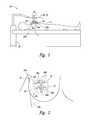
- FIG. 1is a side view of a localization system with a removable implantable device configured in accordance with embodiments of the present technology.
- FIG. 2is a front view of the removable implantable device of FIG. 1 implanted in a resection cavity in accordance with embodiments of the present technology.
- FIGS. 3-6are side views of removable implantable devices configured in accordance with embodiments of the present technology.
- FIG. 7is a partially schematic view illustrating the operation of a localization system configured in accordance with embodiments of the present technology.
- FIG. 8is a side view of a removable implantable device anchored across a resection cavity in accordance with embodiments of the present technology.
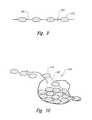
- FIG. 9is a side view of a removable implantable device configured in accordance with embodiments of the present technology.
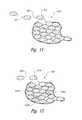
- FIGS. 10-12are a series of side views illustration implantation of the removable implantable device of FIG. 9 in a soft tissue cavity in accordance with embodiments of the present technology.
- an implantable device for guided radiation therapycomprises an active marker configured to be positioned within a capsule configured to be implanted in a cavity of a patient, and to transmit a non-ionizing wireless signal in response to a non-ionizing wirelessly transmitted source energy.
- the devicefurther includes a fastening unit coupled to the active marker and configured to (a) hold the marker at a desired location in the removable implant and (b) recognize deformation of the tissue cavity.
- FIG. 1is a side view of a localization system 10 with an implantable device 20 (identified separately by reference numbers 20 a and 20 b ) for facilitating radiation treatment of a target in accordance with an embodiment of the invention.
- FIG. 2is a front view of the removable implantable device 20 of FIG. 1 implanted in a resection cavity in accordance with another embodiment of the present technology.
- the implantable device 20includes a sheath 30 having a distal tip configured to be inserted into the patient and a second end configured to be outside of the patient.
- the sheath 30can be a catheter, such as a multilumen silicon catheter, or other type of device that can be percutaneously inserted into the breast or other part of the body.
- the implantable device 20further includes a plurality of markers 40 (identified individually as first through fourth markers 40 a - 40 d in FIG. 2 ; only second and third markers 40 b and 40 c are visible in FIG. 1 ).
- the markers 40can comprise wired sensors configured to transmit independent location signals in response to an energy source that is external to the body, and/or one or more of the markers 40 can comprise wired transmitters that transmit source energy to a sensor array that is external to the body.
- the active markers 40can be single coil or multiple coil sensors that produce an electrical current in response to the strength of an externally supplied alternating magnetic field.
- one or more of the active markerscan be a wireless active sensor that wirelessly transmits location signals in response to wirelessly transmitted excitation signals.
- Such wireless active markerscan comprise a casing and a magnetic transponder in the casing as described in U.S. patent application Ser. No. 11/243,478 filed Nov. 14, 2015 and Ser. No. 11/166,801 filed Jun. 24, 2005, both of which are incorporated herein by reference in their entirety.
- the localization system 10can determine the location of the active markers 40 in real-time to facilitate external beam radiation therapy for partial breast irradiation or other therapies.
- the localization system 10can include a controller 80 and a field device 60 , 70 (e.g., including an excitation source 60 and a sensor assembly 70 ).
- the field device 60 , 70can generate one or more alternating magnetic fields that the active markers 40 sense, or the field device 60 , 70 can sense one or more alternating magnetic fields generated by the active markers 40 .
- the controller 80receives location signals from either the field device 60 , 70 or the active markers 40 and determines the actual location of the individual markers 40 in a three-dimensional reference frame when the markers are within or on the patient 6 .
- the localization system 10tracks the three-dimensional coordinates of the markers 40 in real time to an absolute external reference frame during the setup process and while irradiating the patient to mitigate collateral effects on adjacent healthy tissue and to ensure that the desired dosage is applied to the target tissue.
- the system 10has removable implantable devices 20 implanted in a patient 6 relative to a resection cavity 7 .
- Each implantable device 20can include the removable device 30 and the marker 40 contained within the removable device 30 .
- the implantable devices 20 a - binclude markers 40 a - d , respectively.
- the markers 40can be active markers configured to transmit independent location signals in response to an energy source located external to the body of the patient (e.g., outside the dermis of the patient).
- the markers 40can be wireless active sensors that wirelessly transmit location signals in response to wirelessly transmitted excitation signals.
- Such wireless active markerscan comprise a magnetic transponder as described in U.S. patent application Ser. Nos.
- the excitation source 60 of the localization system 10is configured to wirelessly transmit excitation signals to the markers 40
- the sensor assembly 70is configured to measure the location signals wirelessly transmitted from the markers 40 .
- one or more removable implantable devices 20are implanted in the patient 6 such that the markers 40 are at least proximate to the resection cavity 7 .
- the removable implantable devices 20are accordingly associated with the resection cavity such that the implantable device and the markers contained therein move based on the position, rotation, and/or expansion-contraction of the resection cavity 7 .
- the two markers 40 b and 40 care associated with each removable implantable device, but a single marker, two markers, or more than three markers can be used depending on the particular application. Two markers, for example, may be desirable because the target can be located accurately and the relative displacement between the markers over time can be used to monitor the status and position of the resection cavity 7 .
- the localization system 10determines the actual location of the markers 40 in a three-dimensional reference frame when the markers are within or on the patient 6 .
- the localization system 10tracks the three-dimensional coordinates of the markers 40 in real time to an absolute external reference frame during the setup process and while irradiating the patient to mitigate collateral effects on adjacent tissue outside the treatment margin and to ensure that the desired dosage is applied to the target tissue.
- the implantable device 20 for guided radiation therapycomprises an active marker having a circuit configured to be contained in an external sheath which is implanted in a patient and to transmit a wirelessly transmitted location signal from within the patient in response to a wirelessly transmitted source energy.
- the active markertransmits a location signal along a wire.
- the implantable devicecan further include a fastening unit for retaining the marker in a fixed position in the external sheath.
- the markerfor example, can comprise a leadless marker having a circuit with a core and a coil around the core.
- implantable device 20enable accurate determination of the size of the resection cavity 7 within the breast of the patient without taking expensive CT images and manually assessing the images. This aspect is very useful because the shape and size of the resection cavity 7 may change over the course of the treatment. This change could cause the external beam radiation to irradiate healthy tissue but miss targeted tissue. By localizing the relative positions of the markers 40 , changes in the size and shape of the resection cavity 7 can be determined before, during, and after each treatment session to ensure that the desired dose of radiation is accurately delivered to the correct tissue.
- the implantable device 20can also track movement of the resection cavity or other treatment target throughout the course of therapy to accurately deliver external beam radiation within the treatment margin.
- Breast tissuefor example, is soft and pliable such that it may be difficult to hold the treatment target at the isocenter of the external radiation beam.
- the breastis also likely to move during treatment because of thoracic expansion/contraction caused by respiration.
- Several embodiments of the implantable device 20are also useful for detecting movement of the patient or other displacement of the breast in real time during therapy. As a result, the implantable device 20 is expected to provide accurate measurements to confirm the status and the location of the treatment target throughout the course of therapy.
- the implantable device 20also track the rotational orientation of the resection cavity or other target site relative to the body or the radiation beam throughout the course of treatment.
- the rotational orientation of the target sitemay be important in several applications because resection cavities and other targets are generally not spherical such that the rotational orientation affects the profile of the treatment margin relative to the position of the external beam.
- the markers 40can be tracked or otherwise located using the localization system 10 to determine rotational orientation of the target relative to the external beam.
- an implantable device 20 for guided radiation therapycomprise an active marker configured to be pre-loaded into a catheter; the catheter is configured to be removeably implanted in the tissue of a patient.
- the markertransmits a non-ionizing wireless signal in response to a non-ionizing wirelessly transmitted source energy.
- the implantable devicecan further include a stability element coupled to the marker and an explant line.
- the stability elementis configured to hold the marker at fixed location within the catheter (e.g., known location) with respect to a target in the tissue.
- the explant linehas a first portion coupled to the marker and/or the stability element and a second portion configured to be at least proximate to the dermis of the patient.
- a system for fiducials contained in a removable device for use in radiation therapyincludes a removable implant device having a cavity configured to receive a fiducial or marker.
- the removable implant 20 amay for example be a sheath 30 a , a capsule, or a catheter with an internal lumen that is suitable for implantation into human tissue and permits subsequent removal.
- additional removable implant or external sheath featuresinclude a sheath having a distal tip 34 with a decreasing diameter to facilitate percutaneous insertion, for example, a tip design such as a “missile-shaped tip”, to facilitate tissue penetration.
- the sheathmay have leading or trailing components from the tip of lesser diameter that can be used as a “thread.”
- the removable implantmay include micro-perforations such that a liquid-contrast may be used to locate the implant.
- a positioning device 50such as a plastic or nitinol filament or tether, affixed to at least one of a fiducial 40 a , 40 b .
- the positioning devicemay be preformed indents or detents in an interior lumen or cavity of a catheter or external sheath.
- the positioning devicemay be a liquid or gel filling the cavity of the removable implant.
- the positioning devicemay include a fastener 41 a , 41 b ( FIG. 5 ) which retains markers 40 a , 40 b respectively in position within the removable implant.
- additional filament featuresinclude: pre-attachment of one or more fiducials suitable for radiation therapy localization and continuous tracking; may contain one or more special markers that are optimized for imaging, such as ultrasound; may be positioned to a desired location within the sheath by the operators; may be self-coiling such that those portions of the filament protruding from the sheath can assume a low-profile on the skin; and may be fixed to the sheath.
- one or more fiducials or active markers 40can be configured to be embedded, attached, or contained within an implantable, removable device such as an external sheath.
- the fiducialsare secured to the positioning device or filament such that in operation, the fiducial is moveable within the external sheath.
- the fiducialsare suitable to enable localization and continuous tracking during radiation therapy.
- the fiducial or the filamentmay be imagable by ultrasound, x-ray, or magnetic resonance when inside the sheath.
- a retention device 32such as a plastic disk or other low-profile securing element, can be slipped over or around the sheath and/or filament and then secured to the patient surface by, for example, a temporary adhesive to hold the sheath and filament in a stable position within the tissue.
- a fastener featuremay include a reversible release mechanism for use in repositioning the filament.
- Yet another aspect of the retention device 32is to provide a low-profile device to maintain patient comfort during use.
- FIG. 7is a schematic view illustrating the operation of an embodiment of the localization system 10 and markers 40 a - c for treating a target in the breast of the patient.
- the markers 40 a - care used to determine the location, orientation, shape, size, and/or other parameter of a resection cavity or other target before, during, and after radiation sessions. More specifically, the localization system 10 determines the locations of the markers 40 a - c and provides objective target position data to a memory, user interface, linear accelerator, and/or other devices in real time during setup, treatment, deployment, simulation, surgery, and/or other medical procedures.
- real timemeans that indicia of objective coordinates are provided to a user interface at (a) a sufficiently high refresh rate (i.e., frequency) such that pauses in the data are not humanly discernable and (b) a sufficiently low latency to be at least substantially contemporaneous with the measurement of the original signal.
- real timeis defined by higher frequency ranges and lower latency ranges for providing the objective data, or in still other embodiments, real time is defined as providing objective data responsive to the location of the markers (e.g., at a periodicity or frequency that adequately tracks the location of the target in real time and/or at a latency that is at least substantially contemporaneous with obtaining position data of the markers).
- the excitation source 60(e.g., pulsed magnetic field generator), sensor assembly 70 , and controller 80 operate together to localize the markers 40 .
- the excitation source 60generates an excitation energy to energize at least one of the markers 40 a - c in the patient 6 .
- the embodiment of the excitation source 60 shown in FIG. 5produces a pulsed magnetic field at different frequencies.
- the excitation source 60can frequency multiplex the magnetic field at a first frequency E 1 to energize the first marker 40 a , a second frequency E 2 to energize the second marker 40 b , and a third frequency E 3 to energize the third marker 40 c .
- the markers 40 a - cIn response to the excitation energy, the markers 40 a - c generate location signals L 1 - 3 at unique response frequencies.
- the first marker 40 agenerates a first location signal L 1 at a first frequency in response to the excitation energy at the first frequency E 1
- the second marker 40 bgenerates a second location signal L 2 at a second frequency in response to the excitation energy at the second frequency E 2
- the third marker 40 cgenerates a third location signal L 3 at a third frequency in response to the excitation energy at the third frequency E 3 .
- the excitation sourcegenerates the magnetic field at frequencies E 1 and E 2
- the markers 40 a - bgenerate location signals L 1 and L 2 , respectively.
- the sensor assembly 70can include a plurality of coils to sense the location signals L 1 - 3 from the markers 40 a - c .
- the sensor assembly 70can be a flat panel having a plurality of coils that are at least substantially coplanar relative to each other. In other embodiments, the sensor assembly 70 may be a non-planar array of coils.
- the controller 80includes hardware, software, or other computer-operable media containing instructions that operate the excitation source 60 to multiplex the excitation energy at the different frequencies E 1 - 3 .
- the controller 80causes the excitation source 60 to generate the excitation energy at the first frequency E 1 for a first excitation period, and then the controller 80 causes the excitation source 60 to terminate the excitation energy at the first frequency E 1 for a first sensing phase during which the sensor assembly 70 senses the first location signal L 1 from the first marker 40 a without the presence of the excitation energy at the first frequency E 1 .
- the controller 80then causes the excitation source 60 to (a) generate the second excitation energy at the second frequency E 2 for a second excitation period; and (b) terminate the excitation energy at the second frequency E 2 for a second sensing phase during which the sensor assembly 70 senses the second location signal L 2 from the second marker 40 b without the presence of the second excitation energy at the second frequency E 2 .
- the controller 80then repeats this operation with the third excitation energy at the third frequency E 3 such that the third marker 40 c transmits the third location signal L 3 to the sensor assembly 70 during a third sensing phase.
- the excitation source 60wirelessly transmits the excitation energy in the form of pulsed magnetic fields at the resonant frequencies of the markers 40 a - c during excitation periods, and the markers 40 a - c wirelessly transmit the location signals L 1 - 3 to the sensor assembly 70 during sensing phases. It will be appreciated that the excitation and sensing phases can be repeated to permit averaging of the sensed signals to reduce noise.
- the computer-operable media in the controller 80also includes instructions to determine the absolute positions of each of the markers 40 a - c in a three-dimensional reference frame. Based on signals provided by the sensor assembly 70 that correspond to the magnitude of each of the location signals L 1 - 3 , the controller 80 and/or a separate signal processor calculates the absolute coordinates of each of the markers 40 a - c in the three-dimensional reference frame.
- An embodiment of such a methodcomprises implanting an active marker in tissue of the patient at the resection cavity, wherein the active marker is configured to transmit a non-ionizing wireless signal in response to a non-ionizing wirelessly transmitted source energy, and wherein the marker is coupled to a fastening unit having a distal first portion and a proximal second portion.
- the methodcan further include securing the second portion of the fastening unit at least proximate to the dermis of the patient, and localizing the active marker by wirelessly transmitting a non-ionizing source energy to the active marker, transmitting a non-ionizing location signal from the active marker in response to the source energy, and calculating a position of the active marker in an external coordinate system based on the location signal.
- the localization system 10 and markers 40enable real time tracking of the target and/or status of the resection cavity or other target relative to an external reference frame outside the patient during treatment planning, setup, irradiation sessions, and other times of the radiation therapy process.
- real time trackingmeans collecting position data of the markers, determining the locations of the markers in an external reference frame (i.e., a reference frame outside the patient), and providing an objective output in the external reference frame responsive to the location of the markers.
- the objective outputis provided at a frequency/periodicity that adequately tracks the target in real time and/or a latency that is at least substantially contemporaneous with collecting the position data (e.g., within a generally concurrent period of time).
- real time trackingis defined as determining the locations of the markers and calculating the locations relative to an external reference frame at (a) a sufficiently high frequency/periodicity so that pauses in representations of the target location at a user interface do not interrupt the procedure or are readily discernable by a human, and (b) a sufficiently low latency to be at least substantially contemporaneous with the measurement of the location signals from the markers.
- real timemeans that the localization system 10 calculates the absolute position of each individual marker 40 and/or the location of the target at a periodicity of approximately 1 ms to 5 seconds, or in many applications at a periodicity of approximately 10-100 ms, or in some specific applications at a periodicity of approximately 20-50 ms.
- the periodicitycan be 12.5 ms (i.e., a frequency of 80 Hz), 16.667 ms (60 Hz), 20 ms (50 Hz), and/or 50 ms (20 Hz).
- real time trackingcan further mean that the localization system 10 provides the absolute locations of the markers 40 and/or the target to a memory device, user interface, linear accelerator, or other device within a latency of 10 ms to 5 seconds from the time the localization signals were transmitted from the markers 40 .
- the localization system 10generally provides the locations of the markers 40 , target, or an instrument within a latency of about 20-50 ms. The localization system 10 accordingly provides real time tracking to monitor the position of the markers 40 and/or the target with respect to an external reference frame in a manner that is expected to enhance the efficacy of radiation therapy.
- real time trackingcan further mean that the localization system 10 provides the absolute locations of the markers 40 and/or the target to a memory device, user interface, or other device within a latency of 10 ms to 5 seconds from the time the localization signals were transmitted from the markers 40 .
- the location systemgenerally provides the locations of the markers 40 and/or target within a latency of about 20-50 ms.
- the localization system 10accordingly provides real time tracking to monitor the position of the markers 40 and/or the target with respect to an external reference frame in a manner that is expected to enhance the efficacy of radiation therapy because higher radiation doses can be applied to the target and collateral effects to healthy tissue can be mitigated.
- real-time trackingcan further be defined by the tracking error.
- Measurements of the position of a moving targetare subject to motion-induced error, generally referred to as a tracking error.
- the localization system 10 and at least one marker 40enable real time tracking of the target or other instrument relative to an external reference frame with a tracking error that is within clinically meaningful limits.
- Tracking errorsare due to two limitations exhibited by any practical measurement system, specifically (a) latency between the time the target position is sensed and the time the position measurement is made available, and (b) sampling delay due to the periodicity of measurements. For example, if a target is moving at 5 cm/s and a measurement system has a latency of 200 ms, then position measurements will be in error by 1 cm. The error in this example is due to latency alone, independent of any other measurement errors, and is simply due to the fact that the target or instrument has moved between the time its position is sensed and the time the position measurement is made available for use. If the measurement system further has a sampling periodicity of 200 ms (i.e., a sampling frequency of 5 Hz), then the peak tracking error increases to 2 cm, with an average tracking error of 1.5 cm.
- a sampling periodicityi.e., a sampling frequency of 5 Hz
- real time trackingrefers to measurement of target position and/or rotation with tracking errors that are within clinically meaningful limits.
- the radiation targetsuch as a lumpectomy cavity in the breast
- the approximate geometric center (AGC) of the targetis roughly determined by the operators, potentially assisted by imaging software tools.
- One or more reference points to the AGC on the patient's skincan be placed.
- the insertion trajectories about the AGC for the fiducial sheathare determined by the operators, such that the sheaths when placed will be in general proximity to the AGC. Entrance and exit sites for the sheaths on the skin will be selected.
- a sheath placed into the lumpectomy cavityfor purposes of injecting contrast into the cavity or removing fluid from that cavity.
- An appropriate anestheticif needed, is administered to the patient by the surgeon, such as a lidocaine infiltration at the entrance and exit points on the skin and along the projected insertion path.
- a needleis passed from an entrance point on the skin to its corresponding skin exit point.
- the sheath (or tail component)is then threaded into the needle.
- the insertion needle and sheath assemblyis then pulled through the tissue.
- the “missile tip” of the sheathfacilitates skin and tissue penetration. Continuous or repeated imaging can be conducted to assess the sheath position relative to the target or GC.
- the skin fastenercan next be applied to provide initial sheath stabilization within the tissue, taking care not to occlude the sheath lumen.
- the sheath portions protruding from the skincan be trimmed to the desired length.
- One or more sheathscould be inserted.
- a filament containing an array of fiducials or specialized markersis then threaded into the sheath.
- the markersmay be pre-loaded or an alternative marker positioning device may be employed to place the markers relative to the removable implant.
- the filamentis positioned such that the fiducials are in proximity to the AGC. This can be assisted by imaging, for example, by ultrasound. For example, an ultrasound image plane through the AGC and the sheath is obtained by the operator. Next, the filament is pulled through the plane until a desired point of that filament is reached as demarked by an ultrasonic marker (which can be the fiducial or a separate marker).
- an actionis applied to the fastener such that the filament is secured within the sheath to prevent subsequent filament movement. Excess filament protruding from the sheath can be trimmed, if desired. A temporary dressing can be placed over the fastener and protruding filament.
- the patientundergoes standard radiation planning simulation.
- an imageusually a CT scan
- a preliminary assessment of the targetis obtained.
- contrastcan be injected into the cavity through one or more of the sheaths to facilitate imaging of the cavity.
- the fastenercan be loosened sufficiently to allow the filament to be repositioned. Once it's determined that fiducial position relative to the AGC is satisfactory, the fastener is closed to secure the filament within the sheath. This realignment process can be made one or more time during the course of radiation therapy should it be necessary.
- the prescribed course of radiation therapyis delivered.
- the fiducialsare used to setup and continuously track the patient during treatment.
- the fiducialscan be used to adapt the radiation to the patient. For example, if the distances between the fiducials changes, they might suggest that there has been some deformation of the target, such as swelling of the lumpectomy cavity. This change may suggest that repeat simulation and re-planning might be indicated.
- the fastenersare released and the sheath containing the fiducial filament is removed.
- the removable implantis removed concurrent with the marker removal.
- one or more catheters 800is anchored on breast surface 802 that pass such that the catheters 800 pass through a cavity 810 .
- tension on the catheter 800prevents movement. Similar to interstitial breast brachytherapy; this configuration can be done at time of biopsy or via ultrasound. Furthermore, cavity shrinkage or expansion can be adjusted for cinching buttons 806 . Additionally, this configuration is operationally quite simple or from a regulator perspective, a 510 K may be obtained (predicate is breast brachytherapy, existing FDA approved brachycaths).
- transponders 820 a , 820 bcould be after-loaded into catheter to be at COM.
- the catheter 800may be rigid or semi-rigid.
- an alternative embodimentincludes a flexible train of repeating interconnectors 902 and capsules 910 .
- the capsules 910may be semi-rigid so as not to be deformable; and may further be potentially filled with an imaging agent or composed of a radiographic visible material.
- the interconnectors 902may be flexible, so as to let the capsules fold upon themselves; sufficiently strong so as to be removable.
- marker or transponders 920may be embedded in capsule 902 or interconnector 910 .
- irregular soft tissue cavity created by a surgical procedureis filled with a string of capsules.
- the surgeonfills the cavity with the device shown in FIG. 9 , taking care to pack any crevices.
- the excessis trimmed once the cavity is filled.
- the deviceserves to smooth and maintain the shape of the cavity.
- Capsulesoutline cavity boundaries on a subsequent imaging study. Capsules can be radiopague or filled with an imaging agent.
- the capsules or interconnectorscould have transponders integrated into them to guide external beam irradiation.
Landscapes
- Health & Medical Sciences (AREA)
- Engineering & Computer Science (AREA)
- Biomedical Technology (AREA)
- Life Sciences & Earth Sciences (AREA)
- Animal Behavior & Ethology (AREA)
- Nuclear Medicine, Radiotherapy & Molecular Imaging (AREA)
- Veterinary Medicine (AREA)
- Public Health (AREA)
- General Health & Medical Sciences (AREA)
- Surgery (AREA)
- Pathology (AREA)
- Radiology & Medical Imaging (AREA)
- Molecular Biology (AREA)
- Medical Informatics (AREA)
- Heart & Thoracic Surgery (AREA)
- Robotics (AREA)
- Oral & Maxillofacial Surgery (AREA)
- Radiation-Therapy Devices (AREA)
Abstract
Description
Claims (15)
Priority Applications (1)
| Application Number | Priority Date | Filing Date | Title |
|---|---|---|---|
| US12/563,084US9943704B1 (en) | 2009-01-21 | 2009-09-18 | Method and system for fiducials contained in removable device for radiation therapy |
Applications Claiming Priority (2)
| Application Number | Priority Date | Filing Date | Title |
|---|---|---|---|
| US14625709P | 2009-01-21 | 2009-01-21 | |
| US12/563,084US9943704B1 (en) | 2009-01-21 | 2009-09-18 | Method and system for fiducials contained in removable device for radiation therapy |
Publications (1)
| Publication Number | Publication Date |
|---|---|
| US9943704B1true US9943704B1 (en) | 2018-04-17 |
Family
ID=61872817
Family Applications (1)
| Application Number | Title | Priority Date | Filing Date |
|---|---|---|---|
| US12/563,084Expired - Fee RelatedUS9943704B1 (en) | 2009-01-21 | 2009-09-18 | Method and system for fiducials contained in removable device for radiation therapy |
Country Status (1)
| Country | Link |
|---|---|
| US (1) | US9943704B1 (en) |
Cited By (2)
| Publication number | Priority date | Publication date | Assignee | Title |
|---|---|---|---|---|
| CN115068124A (en)* | 2021-03-12 | 2022-09-20 | 常州朗合医疗器械有限公司 | Medical marking device and taking and placing method thereof |
| US20240156923A1 (en)* | 2012-09-06 | 2024-05-16 | Norwegian University Of Science And Technology (Ntnu) | Intervention Device |
Citations (164)
| Publication number | Priority date | Publication date | Assignee | Title |
|---|---|---|---|---|
| US3967161A (en) | 1972-06-14 | 1976-06-29 | Lichtblau G J | A multi-frequency resonant tag circuit for use with an electronic security system having improved noise discrimination |
| US4023167A (en) | 1975-06-16 | 1977-05-10 | Wahlstrom Sven E | Radio frequency detection system and method for passive resonance circuits |
| US4114601A (en) | 1976-08-09 | 1978-09-19 | Micro Tec Instrumentation, Inc. | Medical and surgical implement detection system |
| US4123749A (en) | 1976-04-03 | 1978-10-31 | Bizerba-Werke Wilhelm Kraut Kg | Method and system for determining the presence of objects within a particular surveillance area, in particular for prevention of shoplifting |
| US4127110A (en) | 1976-05-24 | 1978-11-28 | Huntington Institute Of Applied Medical Research | Implantable pressure transducer |
| US4160971A (en) | 1975-05-02 | 1979-07-10 | National Research Development Corporation | Transponders |
| US4222374A (en) | 1978-06-16 | 1980-09-16 | Metal Bellows Corporation | Septum locating apparatus |
| US4260990A (en) | 1979-11-08 | 1981-04-07 | Lichtblau G J | Asymmetrical antennas for use in electronic security systems |
| US4393872A (en) | 1980-05-27 | 1983-07-19 | Eder Instrument Co., Inc. | Aspirating surgical forceps |
| US4618822A (en) | 1984-04-18 | 1986-10-21 | Position Orientation Systems, Ltd. | Displacement sensing device utilizing adjustable tuned circuit |
| US4633250A (en) | 1985-01-07 | 1986-12-30 | Allied Corporation | Coplanar antenna for proximate surveillance systems |
| US4643196A (en) | 1984-10-24 | 1987-02-17 | Hakko Electric Machine Works Co., Ltd. | Biopsy needle set |
| US4653496A (en) | 1985-02-01 | 1987-03-31 | Bundy Mark A | Transluminal lysing system |
| US4696287A (en) | 1985-02-26 | 1987-09-29 | Hortmann Gmbh | Transmission system for implanted hearing aids |
| US4795995A (en) | 1984-09-17 | 1989-01-03 | Progressive Dynamics, Inc. | Method and apparatus for producing electromagnetic surveillance fields |
| US4799495A (en) | 1987-03-20 | 1989-01-24 | National Standard Company | Localization needle assembly |
| US4909789A (en) | 1986-03-28 | 1990-03-20 | Olympus Optical Co., Ltd. | Observation assisting forceps |
| US4936823A (en) | 1988-05-04 | 1990-06-26 | Triangle Research And Development Corp. | Transendoscopic implant capsule |
| US4945914A (en) | 1987-11-10 | 1990-08-07 | Allen George S | Method and apparatus for providing related images over time of a portion of the anatomy using at least four fiducial implants |
| US4994079A (en) | 1989-07-28 | 1991-02-19 | C. R. Bard, Inc. | Grasping forceps |
| US5031634A (en) | 1990-01-19 | 1991-07-16 | Beth Israel Hospital Assoc., Inc. | Adjustable biopsy needle-guide device |
| US5062847A (en) | 1990-12-31 | 1991-11-05 | Barnes William E | Laparoscopic retractor |
| US5095224A (en) | 1990-08-31 | 1992-03-10 | Siemens-Pacesetter, Inc. | Interrupted resonance energy transfer system |
| US5099845A (en) | 1989-05-24 | 1992-03-31 | Micronix Pty Ltd. | Medical instrument location means |
| US5107862A (en) | 1991-05-06 | 1992-04-28 | Fabian Carl E | Surgical implement detector utilizing a powered marker |
| US5142292A (en) | 1991-08-05 | 1992-08-25 | Checkpoint Systems, Inc. | Coplanar multiple loop antenna for electronic article surveillance systems |
| US5170055A (en) | 1990-07-25 | 1992-12-08 | Care Wise Medical Products Corporation | Radiation detecting biopsy probe |
| US5325873A (en) | 1992-07-23 | 1994-07-05 | Abbott Laboratories | Tube placement verifier system |
| US5353804A (en) | 1990-09-18 | 1994-10-11 | Peb Biopsy Corporation | Method and device for percutaneous exisional breast biopsy |
| US5409004A (en) | 1993-06-11 | 1995-04-25 | Cook Incorporated | Localization device with radiopaque markings |
| US5423744A (en) | 1992-12-22 | 1995-06-13 | Gencheff; Nelson | Catheter system for the deployment of biological material |
| US5423334A (en) | 1993-02-01 | 1995-06-13 | C. R. Bard, Inc. | Implantable medical device characterization system |
| US5425382A (en) | 1993-09-14 | 1995-06-20 | University Of Washington | Apparatus and method for locating a medical tube in the body of a patient |
| US5425367A (en) | 1991-09-04 | 1995-06-20 | Navion Biomedical Corporation | Catheter depth, position and orientation location system |
| US5431161A (en) | 1993-04-15 | 1995-07-11 | Adac Laboratories | Method and apparatus for information acquistion, processing, and display within a medical camera system |
| US5446548A (en) | 1993-10-08 | 1995-08-29 | Siemens Medical Systems, Inc. | Patient positioning and monitoring system |
| WO1996003925A1 (en) | 1994-08-05 | 1996-02-15 | Origin Medsystems, Inc. | Surgical helical fastener with applicator |
| US5509900A (en) | 1992-03-02 | 1996-04-23 | Kirkman; Thomas R. | Apparatus and method for retaining a catheter in a blood vessel in a fixed position |
| US5528651A (en) | 1994-06-09 | 1996-06-18 | Elekta Instrument Ab | Positioning device and method for radiation treatment |
| US5626630A (en) | 1994-10-13 | 1997-05-06 | Ael Industries, Inc. | Medical telemetry system using an implanted passive transponder |
| US5638819A (en) | 1995-08-29 | 1997-06-17 | Manwaring; Kim H. | Method and apparatus for guiding an instrument to a target |
| US5651043A (en) | 1994-03-25 | 1997-07-22 | Kabushiki Kaisha Toshiba | Radiotherapy system |
| US5680106A (en) | 1995-10-27 | 1997-10-21 | International Business Machines Corporation | Multibit tag with stepwise variable frequencies |
| US5697384A (en) | 1993-03-26 | 1997-12-16 | Surge Miyawaki Co., Ltd. | Internal identification apparatus for animals |
| US5707362A (en) | 1992-04-15 | 1998-01-13 | Yoon; Inbae | Penetrating instrument having an expandable anchoring portion for triggering protrusion of a safety member and/or retraction of a penetrating member |
| US5707390A (en) | 1990-03-02 | 1998-01-13 | General Surgical Innovations, Inc. | Arthroscopic retractors |
| US5711299A (en) | 1996-01-26 | 1998-01-27 | Manwaring; Kim H. | Surgical guidance method and system for approaching a target within a body |
| US5727552A (en) | 1996-01-11 | 1998-03-17 | Medtronic, Inc. | Catheter and electrical lead location system |
| US5735795A (en) | 1995-07-20 | 1998-04-07 | Picker International, Inc. | Marker for magnetic resonance imaging |
| US5748767A (en) | 1988-02-01 | 1998-05-05 | Faro Technology, Inc. | Computer-aided surgery apparatus |
| US5757881A (en) | 1997-01-06 | 1998-05-26 | Siemens Business Communication Systems, Inc. | Redundant field-defining arrays for a radiation system |
| US5764052A (en) | 1995-06-16 | 1998-06-09 | Pacesetter, Inc. | Coil return energy measurement magnetic field sensor and method thereof |
| US5769861A (en) | 1995-09-28 | 1998-06-23 | Brainlab Med. Computersysteme Gmbh | Method and devices for localizing an instrument |
| US5810851A (en) | 1996-03-05 | 1998-09-22 | Yoon; Inbae | Suture spring device |
| US5815076A (en) | 1996-01-16 | 1998-09-29 | Sensormatic Electronics Corporation | Pulsed-signal magnetomechanical electronic article surveillance system with improved damping of transmitting antenna |
| US5840148A (en) | 1995-06-30 | 1998-11-24 | Bio Medic Data Systems, Inc. | Method of assembly of implantable transponder |
| US5868673A (en) | 1995-03-28 | 1999-02-09 | Sonometrics Corporation | System for carrying out surgery, biopsy and ablation of a tumor or other physical anomaly |
| US5879297A (en) | 1997-05-08 | 1999-03-09 | Lucent Medical Systems, Inc. | System and method to determine the location and orientation of an indwelling medical device |
| US5902310A (en) | 1996-08-12 | 1999-05-11 | Ethicon Endo-Surgery, Inc. | Apparatus and method for marking tissue |
| US5910144A (en) | 1998-01-09 | 1999-06-08 | Endovascular Technologies, Inc. | Prosthesis gripping system and method |
| US5911717A (en) | 1997-03-17 | 1999-06-15 | Precision Vascular Systems, Inc. | Catheter deliverable thrombogenic apparatus and method |
| US5928137A (en) | 1996-05-03 | 1999-07-27 | Green; Philip S. | System and method for endoscopic imaging and endosurgery |
| US5941890A (en) | 1998-06-26 | 1999-08-24 | Ethicon Endo-Surgery, Inc. | Implantable surgical marker |
| US5951481A (en) | 1996-09-20 | 1999-09-14 | Critikon Company, L.L.C. | Apparatus and method for non-invasive measurement of a substance |
| US5951514A (en) | 1997-03-07 | 1999-09-14 | Sahota; Harvinder | Multi-lobe perfusion balloon |
| US5957934A (en) | 1997-12-22 | 1999-09-28 | Uri Rapoport | Method and apparatus for guiding a penetrating tool into a three-dimensional object |
| US5989265A (en) | 1995-03-08 | 1999-11-23 | Bouquet De La Joliniere; Jean Henri | Device for pinpointing suspect lesions of the breast and apparatus for positioning it |
| US6026818A (en) | 1998-03-02 | 2000-02-22 | Blair Port Ltd. | Tag and detection device |
| WO2000016686A2 (en) | 1998-09-24 | 2000-03-30 | Data Sciences International, Inc. | Implantable sensor with wireless communication |
| US6059734A (en) | 1995-01-06 | 2000-05-09 | Yoon; Inbae | Methods of collecting tissue at obstructed anatomical sites |
| US6061644A (en) | 1997-12-05 | 2000-05-09 | Northern Digital Incorporated | System for determining the spatial position and orientation of a body |
| US6066158A (en) | 1996-07-25 | 2000-05-23 | Target Therapeutics, Inc. | Mechanical clot encasing and removal wire |
| US6067465A (en) | 1997-11-26 | 2000-05-23 | General Electric Company | System and method for detecting and tracking reference position changes with linear phase shift in magnetic resonance imaging |
| US6076008A (en) | 1990-10-19 | 2000-06-13 | St. Louis University | System for indicating the position of a surgical probe within a head on an image of the head |
| US6081238A (en) | 1995-05-30 | 2000-06-27 | Sensormatic Electronics Corporation | EAS system antenna configuration for providing improved interrogation field distribution |
| US6082366A (en) | 1995-09-05 | 2000-07-04 | Aesculap Meditec Gmbh | Method and arrangement for determining the position of a marker in an organic cavity |
| US6144875A (en) | 1999-03-16 | 2000-11-07 | Accuray Incorporated | Apparatus and method for compensating for respiratory and patient motion during treatment |
| US6161009A (en) | 1997-08-25 | 2000-12-12 | Hewlett-Packard Company | Latency time determination system for a transceiver |
| US6198963B1 (en) | 1996-07-17 | 2001-03-06 | Biosense, Inc. | Position confirmation with learn and test functions |
| US6222544B1 (en) | 1997-10-17 | 2001-04-24 | Siemens Medical Systems, Inc. | Graphical user interface for radiation therapy treatment apparatus |
| US6220248B1 (en) | 1998-10-21 | 2001-04-24 | Ethicon Endo-Surgery, Inc. | Method for implanting a biopsy marker |
| US6228055B1 (en) | 1994-09-16 | 2001-05-08 | Ethicon Endo-Surgery, Inc. | Devices for marking and defining particular locations in body tissue |
| US6234177B1 (en) | 1999-08-12 | 2001-05-22 | Thomas Barsch | Apparatus and method for deploying an expandable biopsy marker |
| US6246900B1 (en) | 1995-05-04 | 2001-06-12 | Sherwood Services Ag | Head band for frameless stereotactic registration |
| US6272371B1 (en) | 1997-01-03 | 2001-08-07 | Biosense Inc. | Bend-responsive catheter |
| US6307473B1 (en) | 1999-08-24 | 2001-10-23 | Sensormatic Electronics Corporation | Electronic article surveillance transmitter control using target range |
| US6325758B1 (en) | 1997-10-27 | 2001-12-04 | Nomos Corporation | Method and apparatus for target position verification |
| US6336904B1 (en) | 1998-04-07 | 2002-01-08 | Pro Duct Health, Inc. | Methods and devices for the localization of lesions in solid tissue |
| US6353655B1 (en) | 2000-08-23 | 2002-03-05 | Siemens Medical Solutions, Inc. | System and method for calculating fluence contributions from a source plane |
| US6356782B1 (en) | 1998-12-24 | 2002-03-12 | Vivant Medical, Inc. | Subcutaneous cavity marking device and method |
| US6359959B1 (en) | 1992-06-12 | 2002-03-19 | Sherwood Services Ag | System for determining target positions in the body observed in CT image data |
| US6360116B1 (en) | 1998-02-27 | 2002-03-19 | Varian Medical Systems, Inc. | Brachytherapy system for prostate cancer treatment with computer implemented systems and processes to facilitate pre-operative planning and post-operative evaluations |
| US6363940B1 (en) | 1998-05-14 | 2002-04-02 | Calypso Medical Technologies, Inc. | System and method for bracketing and removing tissue |
| US6371904B1 (en) | 1998-12-24 | 2002-04-16 | Vivant Medical, Inc. | Subcutaneous cavity marking device and method |
| US6371379B1 (en) | 1995-07-17 | 2002-04-16 | Flying Null Limited | Magnetic tags or markers |
| US6377162B1 (en) | 1998-11-25 | 2002-04-23 | Ge Medical Systems Global Technology Company, Llc | Medical diagnostic field service method and apparatus |
| US6381485B1 (en) | 1999-10-28 | 2002-04-30 | Surgical Navigation Technologies, Inc. | Registration of human anatomy integrated for electromagnetic localization |
| US6385286B1 (en) | 1998-08-06 | 2002-05-07 | Wisconsin Alumni Research Foundation | Delivery modification system for radiation therapy |
| US6385288B1 (en) | 2001-01-19 | 2002-05-07 | Mitsubishi Denki Kabushiki Kaisha | Radiotherapy apparatus with independent rotation mechanisms |
| US6393096B1 (en) | 1998-05-27 | 2002-05-21 | Nomos Corporation | Planning method and apparatus for radiation dosimetry |
| WO2002039917A1 (en) | 1998-05-14 | 2002-05-23 | Calypso Medical, Inc. | Systems and methods for locating and defining a target location within a human body |
| US20020065461A1 (en) | 1991-01-28 | 2002-05-30 | Cosman Eric R. | Surgical positioning system |
| US20020083951A1 (en)* | 2000-12-27 | 2002-07-04 | Peter Stegmaier | Implantatble identification marker |
| US6416520B1 (en) | 1999-04-23 | 2002-07-09 | Sherwood Services Ag | Microdrive for probes |
| US6425903B1 (en) | 2000-05-09 | 2002-07-30 | James W. Voegele | Implantable surgical marker |
| US6447448B1 (en) | 1998-12-31 | 2002-09-10 | Ball Semiconductor, Inc. | Miniature implanted orthopedic sensors |
| US20020165443A1 (en) | 2001-01-25 | 2002-11-07 | Yasuhiro Mori | Vital signs detection system, vital signs detection method, vital signs processing apparatus, and health control method |
| US20020193685A1 (en) | 2001-06-08 | 2002-12-19 | Calypso Medical, Inc. | Guided Radiation Therapy System |
| US6498944B1 (en) | 1996-02-01 | 2002-12-24 | Biosense, Inc. | Intrabody measurement |
| US6501981B1 (en) | 1999-03-16 | 2002-12-31 | Accuray, Inc. | Apparatus and method for compensating for respiratory and patient motions during treatment |
| US20030023161A1 (en) | 1999-03-11 | 2003-01-30 | Assaf Govari | Position sensing system with integral location pad and position display |
| US6535756B1 (en) | 2000-04-07 | 2003-03-18 | Surgical Navigation Technologies, Inc. | Trajectory storage apparatus and method for surgical navigation system |
| US6574492B1 (en) | 1996-01-08 | 2003-06-03 | Biosense, Inc. | Catheter having multiple arms with electrode and position sensor |
| US20030181794A1 (en)* | 2002-01-29 | 2003-09-25 | Rini Christopher J. | Implantable sensor housing, sensor unit and methods for forming and using the same |
| US6638231B2 (en) | 2000-12-18 | 2003-10-28 | Biosense, Inc. | Implantable telemetric medical sensor and method |
| US20030206610A1 (en) | 2002-05-01 | 2003-11-06 | Collins William F. | Patient positioning system |
| US20030206614A1 (en) | 2000-01-31 | 2003-11-06 | Kendrick Lance A. | Method and apparatus for alignment of medical radiation beams using a body frame |
| US6654629B2 (en) | 2002-01-23 | 2003-11-25 | Valentino Montegrande | Implantable biomarker and method of use |
| US20040068182A1 (en) | 2002-09-18 | 2004-04-08 | Misra Satrajit Chandra | Digitally reconstruced portal image and radiation therapy workflow incorporating the same |
| US6725083B1 (en) | 1999-02-02 | 2004-04-20 | Senorx, Inc. | Tissue site markers for in VIVO imaging |
| US6766186B1 (en) | 1999-06-16 | 2004-07-20 | C. R. Bard, Inc. | Post biospy tissue marker and method of use |
| WO2004061460A2 (en) | 2002-12-30 | 2004-07-22 | Calypso Medical Technologies, Inc. | Implantable marker with a wireless signal transmitter compatible for use in magnetic resonance imaging devices and/or suitable for use in radiation imaging processes |
| US6812842B2 (en) | 2001-12-20 | 2004-11-02 | Calypso Medical Technologies, Inc. | System for excitation of a leadless miniature marker |
| US6822570B2 (en) | 2001-12-20 | 2004-11-23 | Calypso Medical Technologies, Inc. | System for spatially adjustable excitation of leadless miniature marker |
| US6838990B2 (en) | 2001-12-20 | 2005-01-04 | Calypso Medical Technologies, Inc. | System for excitation leadless miniature marker |
| US20050085895A1 (en) | 2003-10-15 | 2005-04-21 | Scimed Life Systems, Inc. | RF-based markers for MRI visualization of medical devices |
| US20050101824A1 (en)* | 2003-11-07 | 2005-05-12 | Proxima Therapeutics, Inc. | Implantable radiotherapy/brachytherapy radiation detecting apparatus and methods |
| US20050113855A1 (en)* | 2003-08-11 | 2005-05-26 | Kennedy Kenneth C.Ii | Surgical implant |
| WO2005067792A1 (en)* | 2004-01-12 | 2005-07-28 | Calypso Medical Technologies, Inc. | Methods and apparatus for stimulating and/or sensing neurons in a patient |
| US20050182319A1 (en) | 2004-02-17 | 2005-08-18 | Glossop Neil D. | Method and apparatus for registration, verification, and referencing of internal organs |
| US6934356B1 (en) | 2003-07-22 | 2005-08-23 | General Electric Company | System and method for dynamic generation of a single user interface for displaying and entry of medical imaging configuration data |
| US6937696B1 (en) | 1998-10-23 | 2005-08-30 | Varian Medical Systems Technologies, Inc. | Method and system for predictive physiological gating |
| US20050273002A1 (en) | 2004-06-04 | 2005-12-08 | Goosen Ryan L | Multi-mode imaging marker |
| US6977504B2 (en) | 2003-12-31 | 2005-12-20 | Calypso Medical Technologies, Inc. | Receiver used in marker localization sensing system using coherent detection |
| US6999555B2 (en) | 2003-09-15 | 2006-02-14 | Varian Medical Systems Imaging Laboratory Gmbh | Systems and methods for processing data |
| WO2006020377A2 (en)* | 2004-07-23 | 2006-02-23 | Calypso Medical Technologies, Inc. | Anchoring wireless markers within a human body |
| US7026927B2 (en) | 2003-12-31 | 2006-04-11 | Calypso Medical Technologies, Inc. | Receiver used in marker localization sensing system and having dithering in excitation pulses |
| US7027707B2 (en) | 2002-12-03 | 2006-04-11 | Japan Aviation Electronics Industry Limited | Aligning implement for optical fibers and optical fiber array fabricated by use of the aligning implement |
| US20060094923A1 (en)* | 2004-10-01 | 2006-05-04 | Calypso Medical Technologies, Inc. | Systems and methods for treating a patient using radiation therapy |
| US20060093089A1 (en)* | 2004-06-24 | 2006-05-04 | Vertatschitsch Edward J | Systems and methods for treating a lung of a patient using guided radiation therapy or surgery |
| US7135978B2 (en) | 2001-09-14 | 2006-11-14 | Calypso Medical Technologies, Inc. | Miniature resonating marker assembly |
| US7142905B2 (en) | 2000-12-28 | 2006-11-28 | Guided Therapy Systems, Inc. | Visual imaging system for ultrasonic probe |
| US7206627B2 (en) | 2002-03-06 | 2007-04-17 | Z-Kat, Inc. | System and method for intra-operative haptic planning of a medical procedure |
| US7213009B2 (en) | 2000-09-21 | 2007-05-01 | Theradoc, Inc. | Systems and methods for manipulating medical data via a decision support system |
| US7221733B1 (en) | 2002-01-02 | 2007-05-22 | Varian Medical Systems Technologies, Inc. | Method and apparatus for irradiating a target |
| US7280863B2 (en) | 2003-10-20 | 2007-10-09 | Magnetecs, Inc. | System and method for radar-assisted catheter guidance and control |
| US7397364B2 (en) | 2003-11-11 | 2008-07-08 | Biosense Webster, Inc. | Digital wireless position sensor |
| US7447643B1 (en) | 2000-09-21 | 2008-11-04 | Theradoc.Com, Inc. | Systems and methods for communicating between a decision-support system and one or more mobile information devices |
| US20080287781A1 (en)* | 2004-03-05 | 2008-11-20 | Depuy International Limited | Registration Methods and Apparatus |
| US7534252B2 (en) | 2000-06-29 | 2009-05-19 | Concentric Medical, Inc. | Systems, methods and devices for removing obstructions from a blood vessel |
| US7558616B2 (en) | 1999-03-11 | 2009-07-07 | Biosense, Inc. | Guidance of invasive medical procedures using implantable tags |
| US7590441B2 (en) | 1999-03-11 | 2009-09-15 | Biosense, Inc. | Invasive medical device with position sensing and display |
| US7599730B2 (en) | 2002-11-19 | 2009-10-06 | Medtronic Navigation, Inc. | Navigation system for cardiac therapies |
| US20090259284A1 (en) | 2008-04-10 | 2009-10-15 | Medtronic Vascular, Inc. | Resonating Stent or Stent Element |
| US7606405B2 (en) | 2003-08-05 | 2009-10-20 | ImQuant LLC | Dynamic tumor diagnostic and treatment system |
| US20090299174A1 (en) | 2004-01-12 | 2009-12-03 | Calypso Medical Technologies, Inc. | Instruments with location markers and methods for tracking instruments through anatomical passageways |
| US7729742B2 (en) | 2001-12-21 | 2010-06-01 | Biosense, Inc. | Wireless position sensor |
| US7780973B2 (en) | 2003-12-15 | 2010-08-24 | Ethicon Endo-Surgery, Inc. | Method and device for minimally invasive implantation of biomaterial |
| US7912529B2 (en) | 2002-12-30 | 2011-03-22 | Calypso Medical Technologies, Inc. | Panel-type sensor/source array assembly |
| US8046052B2 (en) | 2002-11-19 | 2011-10-25 | Medtronic Navigation, Inc. | Navigation system for cardiac therapies |
| US8196589B2 (en) | 2003-12-24 | 2012-06-12 | Calypso Medical Technologies, Inc. | Implantable marker with wireless signal transmitter |
| US8239002B2 (en) | 2004-08-12 | 2012-08-07 | Novatek Medical Ltd. | Guiding a tool for medical treatment by detecting a source of radioactivity |
| US8239005B2 (en) | 2004-07-23 | 2012-08-07 | Varian Medical Systems, Inc. | Systems and methods for real-time tracking of targets in radiation therapy and other medical applications |
| US8549960B2 (en) | 2010-08-11 | 2013-10-08 | William T. Hoff | Tool for adjusting military phone jack |
- 2009
- 2009-09-18USUS12/563,084patent/US9943704B1/ennot_activeExpired - Fee Related
Patent Citations (205)
| Publication number | Priority date | Publication date | Assignee | Title |
|---|---|---|---|---|
| US3967161A (en) | 1972-06-14 | 1976-06-29 | Lichtblau G J | A multi-frequency resonant tag circuit for use with an electronic security system having improved noise discrimination |
| US4160971A (en) | 1975-05-02 | 1979-07-10 | National Research Development Corporation | Transponders |
| US4023167A (en) | 1975-06-16 | 1977-05-10 | Wahlstrom Sven E | Radio frequency detection system and method for passive resonance circuits |
| US4123749A (en) | 1976-04-03 | 1978-10-31 | Bizerba-Werke Wilhelm Kraut Kg | Method and system for determining the presence of objects within a particular surveillance area, in particular for prevention of shoplifting |
| US4127110A (en) | 1976-05-24 | 1978-11-28 | Huntington Institute Of Applied Medical Research | Implantable pressure transducer |
| US4114601A (en) | 1976-08-09 | 1978-09-19 | Micro Tec Instrumentation, Inc. | Medical and surgical implement detection system |
| US4222374A (en) | 1978-06-16 | 1980-09-16 | Metal Bellows Corporation | Septum locating apparatus |
| US4260990A (en) | 1979-11-08 | 1981-04-07 | Lichtblau G J | Asymmetrical antennas for use in electronic security systems |
| US4393872A (en) | 1980-05-27 | 1983-07-19 | Eder Instrument Co., Inc. | Aspirating surgical forceps |
| US4618822A (en) | 1984-04-18 | 1986-10-21 | Position Orientation Systems, Ltd. | Displacement sensing device utilizing adjustable tuned circuit |
| US4795995A (en) | 1984-09-17 | 1989-01-03 | Progressive Dynamics, Inc. | Method and apparatus for producing electromagnetic surveillance fields |
| US4643196A (en) | 1984-10-24 | 1987-02-17 | Hakko Electric Machine Works Co., Ltd. | Biopsy needle set |
| US4633250A (en) | 1985-01-07 | 1986-12-30 | Allied Corporation | Coplanar antenna for proximate surveillance systems |
| US4653496A (en) | 1985-02-01 | 1987-03-31 | Bundy Mark A | Transluminal lysing system |
| US4696287A (en) | 1985-02-26 | 1987-09-29 | Hortmann Gmbh | Transmission system for implanted hearing aids |
| US4909789A (en) | 1986-03-28 | 1990-03-20 | Olympus Optical Co., Ltd. | Observation assisting forceps |
| US4799495A (en) | 1987-03-20 | 1989-01-24 | National Standard Company | Localization needle assembly |
| US4945914A (en) | 1987-11-10 | 1990-08-07 | Allen George S | Method and apparatus for providing related images over time of a portion of the anatomy using at least four fiducial implants |
| US5748767A (en) | 1988-02-01 | 1998-05-05 | Faro Technology, Inc. | Computer-aided surgery apparatus |
| US4936823A (en) | 1988-05-04 | 1990-06-26 | Triangle Research And Development Corp. | Transendoscopic implant capsule |
| US5099845A (en) | 1989-05-24 | 1992-03-31 | Micronix Pty Ltd. | Medical instrument location means |
| US4994079A (en) | 1989-07-28 | 1991-02-19 | C. R. Bard, Inc. | Grasping forceps |
| US5031634A (en) | 1990-01-19 | 1991-07-16 | Beth Israel Hospital Assoc., Inc. | Adjustable biopsy needle-guide device |
| US5707390A (en) | 1990-03-02 | 1998-01-13 | General Surgical Innovations, Inc. | Arthroscopic retractors |
| US5170055A (en) | 1990-07-25 | 1992-12-08 | Care Wise Medical Products Corporation | Radiation detecting biopsy probe |
| US5095224A (en) | 1990-08-31 | 1992-03-10 | Siemens-Pacesetter, Inc. | Interrupted resonance energy transfer system |
| US5353804A (en) | 1990-09-18 | 1994-10-11 | Peb Biopsy Corporation | Method and device for percutaneous exisional breast biopsy |
| US6076008A (en) | 1990-10-19 | 2000-06-13 | St. Louis University | System for indicating the position of a surgical probe within a head on an image of the head |
| US5062847A (en) | 1990-12-31 | 1991-11-05 | Barnes William E | Laparoscopic retractor |
| US20020065461A1 (en) | 1991-01-28 | 2002-05-30 | Cosman Eric R. | Surgical positioning system |
| US6405072B1 (en) | 1991-01-28 | 2002-06-11 | Sherwood Services Ag | Apparatus and method for determining a location of an anatomical target with reference to a medical apparatus |
| US5107862A (en) | 1991-05-06 | 1992-04-28 | Fabian Carl E | Surgical implement detector utilizing a powered marker |
| US5142292A (en) | 1991-08-05 | 1992-08-25 | Checkpoint Systems, Inc. | Coplanar multiple loop antenna for electronic article surveillance systems |
| US5425367A (en) | 1991-09-04 | 1995-06-20 | Navion Biomedical Corporation | Catheter depth, position and orientation location system |
| US5509900A (en) | 1992-03-02 | 1996-04-23 | Kirkman; Thomas R. | Apparatus and method for retaining a catheter in a blood vessel in a fixed position |
| US5707362A (en) | 1992-04-15 | 1998-01-13 | Yoon; Inbae | Penetrating instrument having an expandable anchoring portion for triggering protrusion of a safety member and/or retraction of a penetrating member |
| US6359959B1 (en) | 1992-06-12 | 2002-03-19 | Sherwood Services Ag | System for determining target positions in the body observed in CT image data |
| US5325873A (en) | 1992-07-23 | 1994-07-05 | Abbott Laboratories | Tube placement verifier system |
| US5423744A (en) | 1992-12-22 | 1995-06-13 | Gencheff; Nelson | Catheter system for the deployment of biological material |
| US5423334A (en) | 1993-02-01 | 1995-06-13 | C. R. Bard, Inc. | Implantable medical device characterization system |
| US5697384A (en) | 1993-03-26 | 1997-12-16 | Surge Miyawaki Co., Ltd. | Internal identification apparatus for animals |
| US5431161A (en) | 1993-04-15 | 1995-07-11 | Adac Laboratories | Method and apparatus for information acquistion, processing, and display within a medical camera system |
| US5409004A (en) | 1993-06-11 | 1995-04-25 | Cook Incorporated | Localization device with radiopaque markings |
| US5425382A (en) | 1993-09-14 | 1995-06-20 | University Of Washington | Apparatus and method for locating a medical tube in the body of a patient |
| US5446548A (en) | 1993-10-08 | 1995-08-29 | Siemens Medical Systems, Inc. | Patient positioning and monitoring system |
| US5651043A (en) | 1994-03-25 | 1997-07-22 | Kabushiki Kaisha Toshiba | Radiotherapy system |
| US5754623A (en) | 1994-03-25 | 1998-05-19 | Kabushiki Kaisha Toshiba | Radiotherapy system |
| US5528651A (en) | 1994-06-09 | 1996-06-18 | Elekta Instrument Ab | Positioning device and method for radiation treatment |
| WO1996003925A1 (en) | 1994-08-05 | 1996-02-15 | Origin Medsystems, Inc. | Surgical helical fastener with applicator |
| US7625397B2 (en) | 1994-09-16 | 2009-12-01 | Ethicon Endo-Surgery, Inc. | Methods for defining and marking tissue |
| US8277391B2 (en) | 1994-09-16 | 2012-10-02 | Devicor Medical Products, Inc. | Methods and devices for defining and marking tissue |
| US20050165305A1 (en) | 1994-09-16 | 2005-07-28 | Foerster Seth A. | Methods and devices for defining and marking tissue |
| US7044957B2 (en) | 1994-09-16 | 2006-05-16 | Ethicon Endo-Surgery, Inc. | Devices for defining and marking tissue |
| US20040024304A1 (en) | 1994-09-16 | 2004-02-05 | Foerster Seth A. | Methods and devices for defining and marking tissue |
| US7229417B2 (en) | 1994-09-16 | 2007-06-12 | Ethicon Endo-Surgery, Inc. | Methods for marking a biopsy site |
| US6228055B1 (en) | 1994-09-16 | 2001-05-08 | Ethicon Endo-Surgery, Inc. | Devices for marking and defining particular locations in body tissue |
| US20060074443A1 (en) | 1994-09-16 | 2006-04-06 | Foerster Seth A | Devices and methods for marking a biopsy site |
| US5626630A (en) | 1994-10-13 | 1997-05-06 | Ael Industries, Inc. | Medical telemetry system using an implanted passive transponder |
| US6059734A (en) | 1995-01-06 | 2000-05-09 | Yoon; Inbae | Methods of collecting tissue at obstructed anatomical sites |
| US5989265A (en) | 1995-03-08 | 1999-11-23 | Bouquet De La Joliniere; Jean Henri | Device for pinpointing suspect lesions of the breast and apparatus for positioning it |
| US5868673A (en) | 1995-03-28 | 1999-02-09 | Sonometrics Corporation | System for carrying out surgery, biopsy and ablation of a tumor or other physical anomaly |
| US6246900B1 (en) | 1995-05-04 | 2001-06-12 | Sherwood Services Ag | Head band for frameless stereotactic registration |
| US6081238A (en) | 1995-05-30 | 2000-06-27 | Sensormatic Electronics Corporation | EAS system antenna configuration for providing improved interrogation field distribution |
| US5764052A (en) | 1995-06-16 | 1998-06-09 | Pacesetter, Inc. | Coil return energy measurement magnetic field sensor and method thereof |
| US5840148A (en) | 1995-06-30 | 1998-11-24 | Bio Medic Data Systems, Inc. | Method of assembly of implantable transponder |
| US6371379B1 (en) | 1995-07-17 | 2002-04-16 | Flying Null Limited | Magnetic tags or markers |
| US5735795A (en) | 1995-07-20 | 1998-04-07 | Picker International, Inc. | Marker for magnetic resonance imaging |
| US5638819A (en) | 1995-08-29 | 1997-06-17 | Manwaring; Kim H. | Method and apparatus for guiding an instrument to a target |
| US6082366A (en) | 1995-09-05 | 2000-07-04 | Aesculap Meditec Gmbh | Method and arrangement for determining the position of a marker in an organic cavity |
| US5769861A (en) | 1995-09-28 | 1998-06-23 | Brainlab Med. Computersysteme Gmbh | Method and devices for localizing an instrument |
| US5680106A (en) | 1995-10-27 | 1997-10-21 | International Business Machines Corporation | Multibit tag with stepwise variable frequencies |
| US6574492B1 (en) | 1996-01-08 | 2003-06-03 | Biosense, Inc. | Catheter having multiple arms with electrode and position sensor |
| US5727552A (en) | 1996-01-11 | 1998-03-17 | Medtronic, Inc. | Catheter and electrical lead location system |
| US5815076A (en) | 1996-01-16 | 1998-09-29 | Sensormatic Electronics Corporation | Pulsed-signal magnetomechanical electronic article surveillance system with improved damping of transmitting antenna |
| US5711299A (en) | 1996-01-26 | 1998-01-27 | Manwaring; Kim H. | Surgical guidance method and system for approaching a target within a body |
| US6498944B1 (en) | 1996-02-01 | 2002-12-24 | Biosense, Inc. | Intrabody measurement |
| US5810851A (en) | 1996-03-05 | 1998-09-22 | Yoon; Inbae | Suture spring device |
| US5928137A (en) | 1996-05-03 | 1999-07-27 | Green; Philip S. | System and method for endoscopic imaging and endosurgery |
| US6198963B1 (en) | 1996-07-17 | 2001-03-06 | Biosense, Inc. | Position confirmation with learn and test functions |
| US6066158A (en) | 1996-07-25 | 2000-05-23 | Target Therapeutics, Inc. | Mechanical clot encasing and removal wire |
| US5902310A (en) | 1996-08-12 | 1999-05-11 | Ethicon Endo-Surgery, Inc. | Apparatus and method for marking tissue |
| US5951481A (en) | 1996-09-20 | 1999-09-14 | Critikon Company, L.L.C. | Apparatus and method for non-invasive measurement of a substance |
| US6272371B1 (en) | 1997-01-03 | 2001-08-07 | Biosense Inc. | Bend-responsive catheter |
| US5757881A (en) | 1997-01-06 | 1998-05-26 | Siemens Business Communication Systems, Inc. | Redundant field-defining arrays for a radiation system |
| US5951514A (en) | 1997-03-07 | 1999-09-14 | Sahota; Harvinder | Multi-lobe perfusion balloon |
| US5911717A (en) | 1997-03-17 | 1999-06-15 | Precision Vascular Systems, Inc. | Catheter deliverable thrombogenic apparatus and method |
| US5879297A (en) | 1997-05-08 | 1999-03-09 | Lucent Medical Systems, Inc. | System and method to determine the location and orientation of an indwelling medical device |
| US6161009A (en) | 1997-08-25 | 2000-12-12 | Hewlett-Packard Company | Latency time determination system for a transceiver |
| US6222544B1 (en) | 1997-10-17 | 2001-04-24 | Siemens Medical Systems, Inc. | Graphical user interface for radiation therapy treatment apparatus |
| US6325758B1 (en) | 1997-10-27 | 2001-12-04 | Nomos Corporation | Method and apparatus for target position verification |
| US6067465A (en) | 1997-11-26 | 2000-05-23 | General Electric Company | System and method for detecting and tracking reference position changes with linear phase shift in magnetic resonance imaging |
| US6061644A (en) | 1997-12-05 | 2000-05-09 | Northern Digital Incorporated | System for determining the spatial position and orientation of a body |
| US5957934A (en) | 1997-12-22 | 1999-09-28 | Uri Rapoport | Method and apparatus for guiding a penetrating tool into a three-dimensional object |
| US5910144A (en) | 1998-01-09 | 1999-06-08 | Endovascular Technologies, Inc. | Prosthesis gripping system and method |
| US6360116B1 (en) | 1998-02-27 | 2002-03-19 | Varian Medical Systems, Inc. | Brachytherapy system for prostate cancer treatment with computer implemented systems and processes to facilitate pre-operative planning and post-operative evaluations |
| US6026818A (en) | 1998-03-02 | 2000-02-22 | Blair Port Ltd. | Tag and detection device |
| US6336904B1 (en) | 1998-04-07 | 2002-01-08 | Pro Duct Health, Inc. | Methods and devices for the localization of lesions in solid tissue |
| US6698433B2 (en) | 1998-05-14 | 2004-03-02 | Calypso Medical Technologies, Inc. | System and method for bracketing and removing tissue |
| US20030192557A1 (en) | 1998-05-14 | 2003-10-16 | David Krag | Systems and methods for locating and defining a target location within a human body |
| US6363940B1 (en) | 1998-05-14 | 2002-04-02 | Calypso Medical Technologies, Inc. | System and method for bracketing and removing tissue |
| WO2002039917A1 (en) | 1998-05-14 | 2002-05-23 | Calypso Medical, Inc. | Systems and methods for locating and defining a target location within a human body |
| US6675810B2 (en) | 1998-05-14 | 2004-01-13 | Calypso Medical Technologies, Inc. | System and method for bracketing and removing tissue |
| US8452375B2 (en) | 1998-05-14 | 2013-05-28 | Varian Medical Systems, Inc. | Systems and methods for locating and defining a target location within a human body |
| US6918919B2 (en) | 1998-05-14 | 2005-07-19 | Calypso Medical Technologies, Inc. | System and method for bracketing and removing tissue |
| US6393096B1 (en) | 1998-05-27 | 2002-05-21 | Nomos Corporation | Planning method and apparatus for radiation dosimetry |
| US5941890A (en) | 1998-06-26 | 1999-08-24 | Ethicon Endo-Surgery, Inc. | Implantable surgical marker |
| US6385286B1 (en) | 1998-08-06 | 2002-05-07 | Wisconsin Alumni Research Foundation | Delivery modification system for radiation therapy |
| WO2000016686A2 (en) | 1998-09-24 | 2000-03-30 | Data Sciences International, Inc. | Implantable sensor with wireless communication |
| US6220248B1 (en) | 1998-10-21 | 2001-04-24 | Ethicon Endo-Surgery, Inc. | Method for implanting a biopsy marker |
| US6937696B1 (en) | 1998-10-23 | 2005-08-30 | Varian Medical Systems Technologies, Inc. | Method and system for predictive physiological gating |
| US6377162B1 (en) | 1998-11-25 | 2002-04-23 | Ge Medical Systems Global Technology Company, Llc | Medical diagnostic field service method and apparatus |
| US20050080338A1 (en) | 1998-12-24 | 2005-04-14 | Sirimanne D. Laksen | Biopsy cavity marking device and method |
| US8320994B2 (en) | 1998-12-24 | 2012-11-27 | Devicor Medical Products, Inc. | Biopsy cavity marking device and method |
| US6371904B1 (en) | 1998-12-24 | 2002-04-16 | Vivant Medical, Inc. | Subcutaneous cavity marking device and method |
| US20050080339A1 (en) | 1998-12-24 | 2005-04-14 | Vivant Medical, Inc. | Biopsy cavity marking device |
| US20050059888A1 (en) | 1998-12-24 | 2005-03-17 | Sirimanne D. Laksen | Biopsy cavity marking device and method |
| US7668582B2 (en) | 1998-12-24 | 2010-02-23 | Ethicon Endo-Surgery, Inc. | Biopsy site marker |
| US8306602B2 (en) | 1998-12-24 | 2012-11-06 | Devicor Medical Products, Inc. | Biopsy cavity marking device |
| US20020107437A1 (en) | 1998-12-24 | 2002-08-08 | Sirimanne D. Laksen | Subcutaneous cavity marking device and method |
| US8320993B2 (en) | 1998-12-24 | 2012-11-27 | Devicor Medical Products, Inc. | Subcutaneous cavity marking device |
| US6356782B1 (en) | 1998-12-24 | 2002-03-12 | Vivant Medical, Inc. | Subcutaneous cavity marking device and method |
| US6447448B1 (en) | 1998-12-31 | 2002-09-10 | Ball Semiconductor, Inc. | Miniature implanted orthopedic sensors |
| US6993375B2 (en) | 1999-02-02 | 2006-01-31 | Senorx, Inc. | Tissue site markers for in vivo imaging |
| US7565191B2 (en) | 1999-02-02 | 2009-07-21 | Senorx, Inc. | Tissue site markers for in vivo imaging |
| US7047063B2 (en) | 1999-02-02 | 2006-05-16 | Senorx, Inc. | Tissue site markers for in vivo imaging |
| US6725083B1 (en) | 1999-02-02 | 2004-04-20 | Senorx, Inc. | Tissue site markers for in VIVO imaging |
| US7558616B2 (en) | 1999-03-11 | 2009-07-07 | Biosense, Inc. | Guidance of invasive medical procedures using implantable tags |
| US7590441B2 (en) | 1999-03-11 | 2009-09-15 | Biosense, Inc. | Invasive medical device with position sensing and display |
| US7174201B2 (en) | 1999-03-11 | 2007-02-06 | Biosense, Inc. | Position sensing system with integral location pad and position display |
| US20030023161A1 (en) | 1999-03-11 | 2003-01-30 | Assaf Govari | Position sensing system with integral location pad and position display |
| US7318805B2 (en) | 1999-03-16 | 2008-01-15 | Accuray Incorporated | Apparatus and method for compensating for respiratory and patient motion during treatment |
| US6144875A (en) | 1999-03-16 | 2000-11-07 | Accuray Incorporated | Apparatus and method for compensating for respiratory and patient motion during treatment |
| US6501981B1 (en) | 1999-03-16 | 2002-12-31 | Accuray, Inc. | Apparatus and method for compensating for respiratory and patient motions during treatment |
| US6416520B1 (en) | 1999-04-23 | 2002-07-09 | Sherwood Services Ag | Microdrive for probes |
| US6766186B1 (en) | 1999-06-16 | 2004-07-20 | C. R. Bard, Inc. | Post biospy tissue marker and method of use |
| US6234177B1 (en) | 1999-08-12 | 2001-05-22 | Thomas Barsch | Apparatus and method for deploying an expandable biopsy marker |
| US6307473B1 (en) | 1999-08-24 | 2001-10-23 | Sensormatic Electronics Corporation | Electronic article surveillance transmitter control using target range |
| US6381485B1 (en) | 1999-10-28 | 2002-04-30 | Surgical Navigation Technologies, Inc. | Registration of human anatomy integrated for electromagnetic localization |
| US20030206614A1 (en) | 2000-01-31 | 2003-11-06 | Kendrick Lance A. | Method and apparatus for alignment of medical radiation beams using a body frame |
| US6535756B1 (en) | 2000-04-07 | 2003-03-18 | Surgical Navigation Technologies, Inc. | Trajectory storage apparatus and method for surgical navigation system |
| US6425903B1 (en) | 2000-05-09 | 2002-07-30 | James W. Voegele | Implantable surgical marker |
| US7534252B2 (en) | 2000-06-29 | 2009-05-19 | Concentric Medical, Inc. | Systems, methods and devices for removing obstructions from a blood vessel |
| US6353655B1 (en) | 2000-08-23 | 2002-03-05 | Siemens Medical Solutions, Inc. | System and method for calculating fluence contributions from a source plane |
| US7213009B2 (en) | 2000-09-21 | 2007-05-01 | Theradoc, Inc. | Systems and methods for manipulating medical data via a decision support system |
| US7447643B1 (en) | 2000-09-21 | 2008-11-04 | Theradoc.Com, Inc. | Systems and methods for communicating between a decision-support system and one or more mobile information devices |
| US6638231B2 (en) | 2000-12-18 | 2003-10-28 | Biosense, Inc. | Implantable telemetric medical sensor and method |
| US20020083951A1 (en)* | 2000-12-27 | 2002-07-04 | Peter Stegmaier | Implantatble identification marker |
| US7142905B2 (en) | 2000-12-28 | 2006-11-28 | Guided Therapy Systems, Inc. | Visual imaging system for ultrasonic probe |
| US6385288B1 (en) | 2001-01-19 | 2002-05-07 | Mitsubishi Denki Kabushiki Kaisha | Radiotherapy apparatus with independent rotation mechanisms |
| US20020165443A1 (en) | 2001-01-25 | 2002-11-07 | Yasuhiro Mori | Vital signs detection system, vital signs detection method, vital signs processing apparatus, and health control method |
| US7657301B2 (en) | 2001-06-08 | 2010-02-02 | Calypso Medical Technologies, Inc. | Guided radiation therapy system |
| US20020193685A1 (en) | 2001-06-08 | 2002-12-19 | Calypso Medical, Inc. | Guided Radiation Therapy System |
| US7657302B2 (en) | 2001-06-08 | 2010-02-02 | Calypso Medical Technologies, Inc. | Guided radiation therapy system |
| US7657303B2 (en) | 2001-06-08 | 2010-02-02 | Calypso Medical Technologies, Inc. | Guided radiation therapy system |
| US20090278689A1 (en) | 2001-09-14 | 2009-11-12 | Margo Gisselberg | Miniature resonating marker assembly |
| US7135978B2 (en) | 2001-09-14 | 2006-11-14 | Calypso Medical Technologies, Inc. | Miniature resonating marker assembly |
| US7535363B2 (en) | 2001-09-14 | 2009-05-19 | Calypso Medical Technologies, Inc. | Miniature resonating marker assembly |
| US6838990B2 (en) | 2001-12-20 | 2005-01-04 | Calypso Medical Technologies, Inc. | System for excitation leadless miniature marker |
| US6822570B2 (en) | 2001-12-20 | 2004-11-23 | Calypso Medical Technologies, Inc. | System for spatially adjustable excitation of leadless miniature marker |
| US7176798B2 (en) | 2001-12-20 | 2007-02-13 | Calypso Medical Technologies, Inc. | System for spatially adjustable excitation of leadless miniature marker |
| US6812842B2 (en) | 2001-12-20 | 2004-11-02 | Calypso Medical Technologies, Inc. | System for excitation of a leadless miniature marker |
| US7696876B2 (en) | 2001-12-20 | 2010-04-13 | Calypso Medical Technologies, Inc. | System for spatially adjustable excitation of leadless miniature marker |
| US7729742B2 (en) | 2001-12-21 | 2010-06-01 | Biosense, Inc. | Wireless position sensor |
| US7221733B1 (en) | 2002-01-02 | 2007-05-22 | Varian Medical Systems Technologies, Inc. | Method and apparatus for irradiating a target |
| US6654629B2 (en) | 2002-01-23 | 2003-11-25 | Valentino Montegrande | Implantable biomarker and method of use |
| US20030181794A1 (en)* | 2002-01-29 | 2003-09-25 | Rini Christopher J. | Implantable sensor housing, sensor unit and methods for forming and using the same |
| US7206627B2 (en) | 2002-03-06 | 2007-04-17 | Z-Kat, Inc. | System and method for intra-operative haptic planning of a medical procedure |
| US7206626B2 (en) | 2002-03-06 | 2007-04-17 | Z-Kat, Inc. | System and method for haptic sculpting of physical objects |
| US20030206610A1 (en) | 2002-05-01 | 2003-11-06 | Collins William F. | Patient positioning system |
| US20040068182A1 (en) | 2002-09-18 | 2004-04-08 | Misra Satrajit Chandra | Digitally reconstruced portal image and radiation therapy workflow incorporating the same |
| US8060185B2 (en) | 2002-11-19 | 2011-11-15 | Medtronic Navigation, Inc. | Navigation system for cardiac therapies |
| US8046052B2 (en) | 2002-11-19 | 2011-10-25 | Medtronic Navigation, Inc. | Navigation system for cardiac therapies |
| US8401616B2 (en) | 2002-11-19 | 2013-03-19 | Medtronic Navigation, Inc. | Navigation system for cardiac therapies |
| US7599730B2 (en) | 2002-11-19 | 2009-10-06 | Medtronic Navigation, Inc. | Navigation system for cardiac therapies |
| US8467853B2 (en) | 2002-11-19 | 2013-06-18 | Medtronic Navigation, Inc. | Navigation system for cardiac therapies |
| US7027707B2 (en) | 2002-12-03 | 2006-04-11 | Japan Aviation Electronics Industry Limited | Aligning implement for optical fibers and optical fiber array fabricated by use of the aligning implement |
| US7912529B2 (en) | 2002-12-30 | 2011-03-22 | Calypso Medical Technologies, Inc. | Panel-type sensor/source array assembly |
| WO2004061460A2 (en) | 2002-12-30 | 2004-07-22 | Calypso Medical Technologies, Inc. | Implantable marker with a wireless signal transmitter compatible for use in magnetic resonance imaging devices and/or suitable for use in radiation imaging processes |
| US20080021308A1 (en) | 2002-12-30 | 2008-01-24 | Calypso Medical Technologies, Inc. | Implantable Marker with a Leadless Signal Transmitter Compatible for Use in Magnetic Resonance Devices |
| US7778687B2 (en) | 2002-12-30 | 2010-08-17 | Calypso Medical Technologies, Inc. | Implantable marker with a leadless signal transmitter compatible for use in magnetic resonance devices |
| US7289839B2 (en) | 2002-12-30 | 2007-10-30 | Calypso Medical Technologies, Inc. | Implantable marker with a leadless signal transmitter compatible for use in magnetic resonance devices |
| US6934356B1 (en) | 2003-07-22 | 2005-08-23 | General Electric Company | System and method for dynamic generation of a single user interface for displaying and entry of medical imaging configuration data |
| US7606405B2 (en) | 2003-08-05 | 2009-10-20 | ImQuant LLC | Dynamic tumor diagnostic and treatment system |
| US20050113855A1 (en)* | 2003-08-11 | 2005-05-26 | Kennedy Kenneth C.Ii | Surgical implant |
| US6999555B2 (en) | 2003-09-15 | 2006-02-14 | Varian Medical Systems Imaging Laboratory Gmbh | Systems and methods for processing data |
| US20050085895A1 (en) | 2003-10-15 | 2005-04-21 | Scimed Life Systems, Inc. | RF-based markers for MRI visualization of medical devices |
| US7280863B2 (en) | 2003-10-20 | 2007-10-09 | Magnetecs, Inc. | System and method for radar-assisted catheter guidance and control |
| US20050101824A1 (en)* | 2003-11-07 | 2005-05-12 | Proxima Therapeutics, Inc. | Implantable radiotherapy/brachytherapy radiation detecting apparatus and methods |
| US7397364B2 (en) | 2003-11-11 | 2008-07-08 | Biosense Webster, Inc. | Digital wireless position sensor |
| US7780973B2 (en) | 2003-12-15 | 2010-08-24 | Ethicon Endo-Surgery, Inc. | Method and device for minimally invasive implantation of biomaterial |
| US8196589B2 (en) | 2003-12-24 | 2012-06-12 | Calypso Medical Technologies, Inc. | Implantable marker with wireless signal transmitter |
| US6977504B2 (en) | 2003-12-31 | 2005-12-20 | Calypso Medical Technologies, Inc. | Receiver used in marker localization sensing system using coherent detection |
| US7026927B2 (en) | 2003-12-31 | 2006-04-11 | Calypso Medical Technologies, Inc. | Receiver used in marker localization sensing system and having dithering in excitation pulses |
| US20090299174A1 (en) | 2004-01-12 | 2009-12-03 | Calypso Medical Technologies, Inc. | Instruments with location markers and methods for tracking instruments through anatomical passageways |
| WO2005067792A1 (en)* | 2004-01-12 | 2005-07-28 | Calypso Medical Technologies, Inc. | Methods and apparatus for stimulating and/or sensing neurons in a patient |
| US20050182319A1 (en) | 2004-02-17 | 2005-08-18 | Glossop Neil D. | Method and apparatus for registration, verification, and referencing of internal organs |
| US20080287781A1 (en)* | 2004-03-05 | 2008-11-20 | Depuy International Limited | Registration Methods and Apparatus |
| US20050273002A1 (en) | 2004-06-04 | 2005-12-08 | Goosen Ryan L | Multi-mode imaging marker |
| US20060093089A1 (en)* | 2004-06-24 | 2006-05-04 | Vertatschitsch Edward J | Systems and methods for treating a lung of a patient using guided radiation therapy or surgery |
| US8239005B2 (en) | 2004-07-23 | 2012-08-07 | Varian Medical Systems, Inc. | Systems and methods for real-time tracking of targets in radiation therapy and other medical applications |
| WO2006020377A2 (en)* | 2004-07-23 | 2006-02-23 | Calypso Medical Technologies, Inc. | Anchoring wireless markers within a human body |
| US8239002B2 (en) | 2004-08-12 | 2012-08-07 | Novatek Medical Ltd. | Guiding a tool for medical treatment by detecting a source of radioactivity |
| US20060094923A1 (en)* | 2004-10-01 | 2006-05-04 | Calypso Medical Technologies, Inc. | Systems and methods for treating a patient using radiation therapy |
| US20090259284A1 (en) | 2008-04-10 | 2009-10-15 | Medtronic Vascular, Inc. | Resonating Stent or Stent Element |
| US8549960B2 (en) | 2010-08-11 | 2013-10-08 | William T. Hoff | Tool for adjusting military phone jack |
Cited By (3)
| Publication number | Priority date | Publication date | Assignee | Title |
|---|---|---|---|---|
| US20240156923A1 (en)* | 2012-09-06 | 2024-05-16 | Norwegian University Of Science And Technology (Ntnu) | Intervention Device |
| US12208134B2 (en)* | 2012-09-06 | 2025-01-28 | Norwegian University Of Science And Technology (Ntnu) | Intervention device |
| CN115068124A (en)* | 2021-03-12 | 2022-09-20 | 常州朗合医疗器械有限公司 | Medical marking device and taking and placing method thereof |
Similar Documents
| Publication | Publication Date | Title |
|---|---|---|
| US10653496B2 (en) | Apparatus and methods for implanting objects, such as a bronchoscopically implanting markers in the lung of patients | |
| US11439847B2 (en) | Systems and methods for treating a lung of a patient using guided radiation therapy or surgery | |
| US10293135B2 (en) | Delivery catheter for and method of delivering implant, for example, bronchoscopically implanting a marker in a lung | |
| US8027712B2 (en) | Elongated markers for soft tissue volume identification | |
| US20110130655A1 (en) | Implantable devices and methods for external beam radiation treatments | |
| US20100282983A1 (en) | Systems and methods for positioning patients during tracking of targets in radiation therapy and other medical applications | |
| US20170113066A1 (en) | System to produce anatomical reproducibility and detect motion during a medical treatment and methods of use | |
| US20100298858A1 (en) | Methods and apparatus for external beam radiation treatments of resection cavities | |
| US9943704B1 (en) | Method and system for fiducials contained in removable device for radiation therapy | |
| Sabbas et al. | A novel calibration procedure of MOSFET dosimeters for use to measure in-vivo doses during HDR 192Ir brachytherapy |
Legal Events
| Date | Code | Title | Description |
|---|---|---|---|
| AS | Assignment | Owner name:CALYPSO MEDICAL TECHNOLOGIES, INC., WASHINGTON Free format text:ASSIGNMENT OF ASSIGNORS INTEREST;ASSIGNORS:MATE, TIMOTHY P.;ZELLER, TRICIA V.;DIMMER, STEVEN C.;AND OTHERS;SIGNING DATES FROM 20100224 TO 20100305;REEL/FRAME:024038/0148 | |
| AS | Assignment | Owner name:VARIAN MEDICAL SYSTEMS, INC., CALIFORNIA Free format text:ASSIGNMENT OF ASSIGNORS INTEREST;ASSIGNOR:CALYPSO MEDICAL TECHNOLOGIES, INC.;REEL/FRAME:027238/0701 Effective date:20111115 | |
| FEPP | Fee payment procedure | Free format text:ENTITY STATUS SET TO UNDISCOUNTED (ORIGINAL EVENT CODE: BIG.) | |
| STCF | Information on status: patent grant | Free format text:PATENTED CASE | |
| FEPP | Fee payment procedure | Free format text:MAINTENANCE FEE REMINDER MAILED (ORIGINAL EVENT CODE: REM.); ENTITY STATUS OF PATENT OWNER: LARGE ENTITY | |
| LAPS | Lapse for failure to pay maintenance fees | Free format text:PATENT EXPIRED FOR FAILURE TO PAY MAINTENANCE FEES (ORIGINAL EVENT CODE: EXP.); ENTITY STATUS OF PATENT OWNER: LARGE ENTITY | |
| STCH | Information on status: patent discontinuation | Free format text:PATENT EXPIRED DUE TO NONPAYMENT OF MAINTENANCE FEES UNDER 37 CFR 1.362 | |
| FP | Lapsed due to failure to pay maintenance fee | Effective date:20220417 |