US9943232B2 - Thermometry heating and sensing assembly - Google Patents
Thermometry heating and sensing assemblyDownload PDFInfo
- Publication number
- US9943232B2 US9943232B2US14/612,886US201514612886AUS9943232B2US 9943232 B2US9943232 B2US 9943232B2US 201514612886 AUS201514612886 AUS 201514612886AUS 9943232 B2US9943232 B2US 9943232B2
- Authority
- US
- United States
- Prior art keywords
- flexible circuit
- circuit strip
- heating element
- thermometry
- temperature sensing
- Prior art date
- Legal status (The legal status is an assumption and is not a legal conclusion. Google has not performed a legal analysis and makes no representation as to the accuracy of the status listed.)
- Active, expires
Links
Images


Classifications
- A—HUMAN NECESSITIES
- A61—MEDICAL OR VETERINARY SCIENCE; HYGIENE
- A61B—DIAGNOSIS; SURGERY; IDENTIFICATION
- A61B5/00—Measuring for diagnostic purposes; Identification of persons
- A61B5/01—Measuring temperature of body parts ; Diagnostic temperature sensing, e.g. for malignant or inflamed tissue
- G—PHYSICS
- G01—MEASURING; TESTING
- G01K—MEASURING TEMPERATURE; MEASURING QUANTITY OF HEAT; THERMALLY-SENSITIVE ELEMENTS NOT OTHERWISE PROVIDED FOR
- G01K1/00—Details of thermometers not specially adapted for particular types of thermometer
- G01K1/16—Special arrangements for conducting heat from the object to the sensitive element
- G01K1/18—Special arrangements for conducting heat from the object to the sensitive element for reducing thermal inertia
- G01K13/002—
- G—PHYSICS
- G01—MEASURING; TESTING
- G01K—MEASURING TEMPERATURE; MEASURING QUANTITY OF HEAT; THERMALLY-SENSITIVE ELEMENTS NOT OTHERWISE PROVIDED FOR
- G01K13/00—Thermometers specially adapted for specific purposes
- G01K13/20—Clinical contact thermometers for use with humans or animals
- A—HUMAN NECESSITIES
- A61—MEDICAL OR VETERINARY SCIENCE; HYGIENE
- A61B—DIAGNOSIS; SURGERY; IDENTIFICATION
- A61B2562/00—Details of sensors; Constructional details of sensor housings or probes; Accessories for sensors
- A61B2562/02—Details of sensors specially adapted for in-vivo measurements
- A61B2562/0271—Thermal or temperature sensors
- A—HUMAN NECESSITIES
- A61—MEDICAL OR VETERINARY SCIENCE; HYGIENE
- A61B—DIAGNOSIS; SURGERY; IDENTIFICATION
- A61B2562/00—Details of sensors; Constructional details of sensor housings or probes; Accessories for sensors
- A61B2562/12—Manufacturing methods specially adapted for producing sensors for in-vivo measurements
- A—HUMAN NECESSITIES
- A61—MEDICAL OR VETERINARY SCIENCE; HYGIENE
- A61B—DIAGNOSIS; SURGERY; IDENTIFICATION
- A61B2562/00—Details of sensors; Constructional details of sensor housings or probes; Accessories for sensors
- A61B2562/16—Details of sensor housings or probes; Details of structural supports for sensors
- A61B2562/164—Details of sensor housings or probes; Details of structural supports for sensors the sensor is mounted in or on a conformable substrate or carrier
- Y—GENERAL TAGGING OF NEW TECHNOLOGICAL DEVELOPMENTS; GENERAL TAGGING OF CROSS-SECTIONAL TECHNOLOGIES SPANNING OVER SEVERAL SECTIONS OF THE IPC; TECHNICAL SUBJECTS COVERED BY FORMER USPC CROSS-REFERENCE ART COLLECTIONS [XRACs] AND DIGESTS
- Y10—TECHNICAL SUBJECTS COVERED BY FORMER USPC
- Y10T—TECHNICAL SUBJECTS COVERED BY FORMER US CLASSIFICATION
- Y10T29/00—Metal working
- Y10T29/49—Method of mechanical manufacture
- Y10T29/49002—Electrical device making
- Y10T29/49117—Conductor or circuit manufacturing
- Y10T29/49124—On flat or curved insulated base, e.g., printed circuit, etc.
Definitions
- This applicationis generally directed to the field of medical devices and more specifically to a patient thermometry heating and sensing assembly, including an improved thermometry probe tip design.
- a probeincludes a proximal end that is connected by means of a tethering cord to a device housing, the latter containing a processor and a display.
- the probeis defined by an elongate probe body, including a conically shaped distal probe tip that is configured to retain a temperature sensor or sensing element, as well as a heating element.
- the heating elementis used in order to preheat the probe given the temperature differences between the environment and the core body temperature of a patient at an intended target (e.g., the axilla, rectum, sublingual pocket), so as to effectively shorten the amount of time that is required to take a temperature measurement.
- an intended targete.g., the axilla, rectum, sublingual pocket
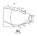
- FIGS. 1 and 2A probe 14 of a prior art thermometry apparatus 10 is illustrated in FIGS. 1 and 2 .
- the probe 14includes a distal probe tip 18 , the latter being defined by a substantially conical shape including a hollow interior.
- the heating elementsuch as an electrical resistor 24
- the temperature sensing elementsuch as a thermistor 28
- Sets of electrical leads 32 , 34in the form of low gauge copper wires, extend proximally from each of the resistor 24 and thermistor 28 , respectively, and further extend through the body of the probe 14 to a connector on the proximal end (not shown) of the probe 14 for attachment to the device housing (not shown).
- the electrical leads 32 , 34provide electrical power to the retained components 24 , 28 and also permit the transmission of signals from the temperature sensing element to the attached device housing (not shown) for processing and display, such as in the course of a typical patient examination.
- the electrical leads 32 , 34extend away from the interior wall mounted components 24 , 28 with little additional support, especially at the mounted ends of the leads 32 , 34 , and are therefore susceptible to breakage. Premature breakage of the electrical leads 32 , 34 frequently requires a complete replacement of the entire thermometry probe 14 , and not just the interior components.
- thermometry assembliesthere is a general and ongoing need to improve the durability and manufacturability of thermometry assemblies, so as to improve their reliability and increase working life.
- thermometry apparatusBecause the temperature sensing element and the heating element are eccentrically mounted to the interior wall of the probe tip, there may also be inconsistencies in terms of heat generation and detection. As a result, there is another general need to improve these characteristics in a thermometry apparatus.
- a temperature measuring apparatuscomprising a distal probe tip having an interior and an inner wall.
- a temperature sensing elementis attached to the inner wall.
- At least one heating elementis attached to the inner wall of the housing, the heating element being further connected to a flexible circuit strip.
- the thermometry apparatuscan include a shaped mandrel which is initially disposed within the probe tip, the mandrel including at least one feature for securing to the flexible circuit strip during the assembly process.
- the flexible circuit stripincludes an opening at a distal end and the mandrel includes a protrusion that is sized to engage the distal opening. In this version, the mandrel is removed from the apparatus prior to final manufacture and test.
- thermometry apparatuscomprising a distal probe tip having a hollow interior.
- An insulating supportis fixedly secured within the interior of the distal probe tip and a temperature sensing element is attached to the insulating support.
- the apparatusfurther comprises at least one heating element that is disposed with the hollow interior of the tip.
- the at least one heating elementcan be attached to the insulating support or to a flexible circuit strip.
- a ceramic disc or other suitably shaped planar memberis used as the insulating support in which the at least one heater element can be disposed on an outer periphery of one side of the support.
- a pair of heater elementscan be disposed on diametrically opposed portions along the outer periphery of the insulating support on a first side thereof.
- a heating elementcan be eliminated entirely from the tip assembly with a temperature sensing element being attached to one side of the support.
- the heater elementsare electrical resistors and the temperature sensing element is a thermistor.
- the temperature sensing elementcan be disposed adjacent the center of the support on a parallel and opposed second surface of the insulating support.
- At least one or each of the heating element(s) and the temperature sensing elementcan be thin-film printed onto respective surfaces of the insulating support.
- a method for configuring a probe tip to measure temperaturecomprising the steps of providing an insulating support, fixedly disposing the insulating support within a hollow interior of the probe tip, and securing a temperature sensing element within the interior of the probe tip.
- at least one heating elementcan be further provided.
- the at least one heating element and the temperature sensing elementare attached to opposite surface of the insulating support.
- the at least one heating elementcan be attached to a flexible circuit strip.
- the supportis made from an insulating material and according to at least one embodiment is made from a ceramic.
- the insulating supportincludes an outer periphery that substantially matches that of the inner wall of the probe tip in which the substrate can be secured using an interference or press fit.
- the supportcan be formed as a disc. According to another version, the insulating support need only match a portion of the internal surface of the probe tip and be fixedly attached therein.
- the at least one heating element and the temperature sensing elementcan be attached to opposing parallel surfaces of the insulating support.
- at least one or each of the temperature sensing element and the at least one heating elementare substrates that are attached to the insulating support by means of thin-film printing.
- only the temperature sensing elementis attached to the insulating support and heating elements are entirely eliminated from the tip assembly.
- a pair of heating elementsare disposed along an outer periphery of the insulating support on one side or surface thereof, the pair of heating elements being substantially diametrically opposed and the temperature sensing element being attached at substantially the center of the opposing side or surface of the insulative support.
- thermometry apparatuscomprising a distal probe tip having a hollow interior, and a temperature sensing element disposed within the hollow interior.
- An insulating supportis at least partially mounted within the interior of the distal probe tip; and at least one of the temperature sensing element and the heating element being attached to the support.
- thermometry apparatusin which a thermometry probe is provided, including a distal probe tip made from a thermally conductive material and in which the probe tip has a hollow interior and an interior wall.
- a temperature sensing elementis attached to the interior wall and a heating element is provided as well as a flexible circuit strip having a distal end that is configured to retain the heating element.
- the heating elementis attached to the flexible circuit strip; and the heating element is attached to the interior wall of the tip.
- thermometry apparatusOne advantage that is provided by the herein described thermometry apparatus is that of a simpler manufacture in which the insulating support can commonly retains at least one or each of the heating element(s) and temperature sensing element.
- the foregoing arrangementsignificantly saves costs in terms of labor and manufacture.
- thermometry probeAnother advantage provided is that of improved reliability and working life of a thermometry probe, wherein the electrical leads to the temperature sensing element and the heating element(s) are less susceptible to premature breakage.
- FIG. 1is a partial sectioned view of a probe tip for a thermometry apparatus in accordance with the prior art
- FIG. 2is a perspective view of a probe for a thermometry apparatus including the probe tip of FIG. 1 ;
- FIG. 3is a partial sectioned view of a thermometry probe tip which is made in accordance with an exemplary embodiment
- FIG. 4is a perspective view of a portion of an exemplary substrate for use in the probe tip of FIG. 3 ;
- FIG. 5is a sectioned side elevational view of a probe tip made in accordance with an exemplary embodiment
- FIG. 6is a bottom facing view of an exemplary substrate for use in a temperature sensing and heating apparatus
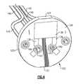
- FIG. 7is a sectioned perspective view of a probe tip of a thermometry apparatus in accordance with another exemplary embodiment
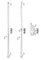
- FIG. 8( a )depicts one side of a flexible circuit strip for use in a thermometry apparatus, such as the apparatus shown in FIG. 7 ;
- FIG. 8( b )depicts the opposite side of the flexible circuit strip depicted in FIG. 8( a ) ;
- FIG. 8( c )is an enlarged view of the distal end of the flexible circuit strip of FIGS. 8( a )-8( b ) .
- thermometry apparatusgenerally relates to a medical thermometry apparatus and more specifically to embodiments of a distal probe tip that retains at least one heating element and a temperature sensor. It will be readily apparent that other variations and modifications are possible. In addition, certain terms are used throughout this discussion to provide a suitable frame of reference in regard to the accompanying drawings. These terms, which include “upper”, “lower”, “inner”, “outer”, “distal”, “proximal” and the like are not intended to limit the scope of the inventive concepts, unless specified otherwise.
- a sectioned partial view of a probe tip 104 in accordance with an exemplary embodimentis shown, and more specifically a distal end 118 thereof.
- the distal end 118 of the probe tip 104is part of a thermometry apparatus 100 , similar to that previously described as part of a temperature probe and having features shown in FIG. 2 , the tip 104 being tethered to an apparatus housing (not shown), which includes various components, including a processor and signal conditioning electronics.
- the probe tip 104according to this exemplary embodiment is defined by a substantially conical configuration having a hollow interior 112 as well as a probe shaft (not shown) extending proximally from the probe tip 104 .
- the probe tip 104is sized and configured for placement relative to a target of interest, such as the axillary region, under the tongue, the rectum or other suitable area of the patient's body (not shown) from which temperature can be reliably measured.
- the temperature probeincluding the probe tip 104 and the extending probe shaft, can be manufactured from a stainless steel or from another suitable material possessing a high thermal conductivity.
- a support 122 made from a ceramic or other suitable electrically insulating materialis fitted within the tip interior 112 .
- the insulating support 122is defined by a planar disk having an inner surface 125 and an opposing outer surface 128 in which the insulating support 122 is sized to create a press fit or an interference fit, as installed within the hollow interior 112 of the probe tip 104 .
- the support 122can assume other shapes, as discussed herein, in which the insulating support 122 is not necessarily required to assume the precise geometry of the internal surface of the probe tip 104 , provided that the support can be securely attached within the confines of the probe tip 104 and is preferably planar in terms of its construction.
- At least one heating element 130is attached to the inner surface 125 of the insulating support 122 and a temperature sensing element 138 is attached to the outer surface 128 of the insulating support 122 .
- the temperature sensing element 138can be, for example, a thermistor or a thermocouple.
- mounting at least one of the above elements 130 , 138 to a fixed component, in this instance the insulating support 122provides advantages in terms of heating and manufacturability of the probe tip 104 .
- the electrical leads (not shown) of the attached components 130 , 138can be more reliably secured within the probe tip 104 and therefore much less prone to premature breakage.
- the heating element 130can be removed entirely with only the temperature sensing element 138 being attached to the insulating support 122 .
- a distal tip 104 of a thermometry apparatus 100includes a hollow interior 112 that is sized to receive an insulating support 122 made from a ceramic or other suitable material.
- the insulating support 122is defined by a disc-like configuration including an inner surface 125 and an opposing outer surface 128 , as well as an outer periphery 123 that is substantially circular with the exception of two flattened portions 127 that are diametrically opposed to one another.
- the flattened portions 127facilitate a fit within the interior of the distal tip 104 with the inner surface 125 facing the proximal end of the probe and the outer surface 128 facing the distal end 118 of the tip 104 .
- a pair of heating elements 130are secured to the inner surface 125 of the insulating support 122 at substantially diametrically opposed portions (i.e., approximately 180 degrees apart) that are adjacent the outer periphery 123 of the support 122 .
- the heating elements 130are each thin-film, thereby providing a substrate which can be printed onto the inner surface 125 of the support 122 .
- a resistor or other heating elementcould be mounted using epoxy, adhesive or other suitable securing means.
- a corresponding set of electrical leads 140each include distal ends 141 that are received within respective openings 144 provided in the insulating support 122 .
- Each opening 144includes a bordering electrically conductive area 147 configured to provide electrical power to each of the resistive (heating) elements 130 , as attached to the insulating support 122 as shown more clearly in FIGS. 4-6 .
- the leads 140are fixedly mounted to the formed openings 144 and placed into electrical contact with the disposed heater elements 130 via the conductive areas 147 .
- At least one temperature sensing element 138is mounted to the outer facing surface 128 of the support 122 according to this embodiment.
- the temperature sensing element 138can be a thin-film, which is printed onto the outer surface 128 of the insulating support 122 .
- other securing meanssuch as an epoxy or suitable adhesive can also be utilized.
- the at least one temperature sensing element 138can be mounted anywhere along the outer surface 128 .
- a single temperature sensing element 138is thin-film printed at about the center of the outer surface 128 and in which a set of electrical leads 140 engage extending conductive portions 139 of the temperature sensing element 138 through a pair of spaced openings 144 provided in the insulating support 122 .
- the insulating support 122can be securely attached within the hollow interior 112 of the probe tip 104 .
- assembly aidssuch as grooves or stops, can be provided in the inner wall 116 of the probe tip 104 to assist in the positioning of the insulating support 122 , which is positioned substantially transverse to the center axis 102 , FIG. 5 , of the probe tip 104 .
- a set of spaced portions(not shown) can be provided on the inner surface of the probe tip 104 .
- the temperature sensing element 138 and the heating elements 130can be secured as substrates using thin-film printing or other suitable means prior to assembly of the insulating support 122 within the interior 112 of the probe tip 104 , and wherein each of the distal ends 141 of the electrical leads 140 can be secured within the openings 144 of the insulating support 122 .
- the heating elements 130can be eliminated entirely from the foregoing assembly with the temperature sensing element 138 being secured to the insulating support 122 .
- thermometry apparatus 100is energized in a known manner such as through a switch provided on the exterior of the device housing (not shown), enabling electrical power to be applied to each of the heating elements 130 and the temperature sensing element 138 as the probe tip 104 is brought into substantial proximity with a target of interest (e.g., the axillary area) of a subject (not shown).
- a target of intereste.g., the axillary area
- the probe tip 104is preheated due to the substantial difference between average body core temperature (98 degrees F.) and that of ambient conditions (65-80 degrees F.) by the application of electrical power (current) to each of the circumferentially disposed heating elements 130 according to this exemplary embodiment.
- the peripheral and circumferential positioning of the conductive areas 147 of the heating elements 130 at the outer periphery 123 of the insulating support 122provides uniformity in heat generation of the insulating support 122 to the probe tip 104 and relative to the nominal temperature of the body (not shown) of the subject, this temperature being uniformly detected by the temperature sensing element 138 .
- the foregoing pre-heating stepwould not be required.
- temperature determinations of the targetcan be made using the contained temperature sensing element 138 wherein the signals, indicative of a change in temperature (e.g., current) are transmitted along the electrical leads 140 to a processor (not shown) of the thermometry apparatus 100 .
- the processorcan be powered by batteries or other source and is further configured to control the operation of the heating elements and conductive areas.
- the herein described probe tip designis also more reliable in terms of performance as compared to known thermometry apparatus. That is and at a minimum, heat generation and heat detection is more efficient, uniform and repeatable.
- the herein described placements of at least one of the heating and temperature sensing elements 130 , 138 to a single component, such as the insulating support 122provides improved stability for each of the mounted electrical leads 140 .
- thermometry apparatus 200includes an elongate probe body 208 having a substantially conical probe tip 204 that is fabricated from a metallic or other thermally conductive material, such as stainless steel.
- the probe tip 204is defined by a hollow interior 212 having an interior circumferential wall 216 .
- the probe body 208is only partially shown in this view, wherein the remainder of the probe body and thermometry apparatus 200 is similar to that depicted in FIG. 2 in which the proximal end of the probe is electrically and mechanically connected by a tether to a housing (not shown) containing a processor, a power source and a display.
- a flexible circuit strip 224 having a set of embedded leadsis attached to the heating element 230 and provides an electrical attachment point for the heating element 230 .
- the heating element 230is attached directly to the interior circumferential wall 216 of the distal probe tip 204 , which allows for the most efficient transfer of heat to the wall 116 .
- the flexible circuit strip 224is sized to extend over the length of the probe body and to the proximal end thereof. As shown, the flexible circuit strip 224 is secured at a distal end 242 to a radial protrusion 237 of a conical mandrel 239 , the latter being initially placed within the hollow interior 212 of the distal probe tip 104 during an assembly operation.
- a temperature sensing element 240such as a thermistor, is further disposed on an opposing side of the interior circumferential wall 216 of the probe tip 204 .
- FIGS. 8( a )-8( c )An exemplary flexible circuit strip 224 is shown in FIGS. 8( a )-8( c ) .
- the flexible circuit strip 224is defined by a flat elongate member made from an insulative material, such as polyimide, and having a set of embedded leads formed in a multi-layered structure.
- the proximal end 246 of the strip 240includes at least one connective feature for mechanical and electrical attachment to a proximal end connector of the probe (not shown), in which the latter is attached to a device housing (not shown) in a manner similar to that shown in FIG. 2 .
- the distal end 242 of the flexible circuit strip 224includes the attachment surface(s) for the heating element 230 .
- a pair of attachment pads 252 , 254are provided in spaced relation to a distal end opening 248 , the latter being sized for reception by the mandrel protrusion 237 .
- the heating element 230is applied to the flexible circuit strip 240 and more specifically the leads of the heating element are directly soldered to the attachment pads 252 , 254 .
- the temperature sensing element 240 , as well as the flexible circuit strip 224 and attached heating element 230are then loaded onto the assembly mandrel 239 with the flexible circuit strip 224 being attached to the extending protrusion 237 of the mandrel 239 through the distal opening 248 of the flexible circuit strip 224 .
- a suitable adhesiveis applied to the outward facing surfaces of the temperature sensing element 240 and the heating element 230 .
- the conical probe tip 204is then slid onto the mandrel 239 and the heating element 230 and the temperature sensing element 240 are adhered to the interior circumferential wall 218 of the probe tip 204 , such as shown in FIG. 7 .
- the mandrel 239can be removed from the interior of the probe tip 204 and discarded.
- the extending leads 241 of the temperature sensing element 240can be attached (soldered) to intermediate attachment pads formed 260 on the flexible circuit strip 224 , according to this exemplary embodiment.
- thermometry apparatus 200can be energized using a switch or other actuable element on the housing (not shown), which creates the preheating of the probe tip upon the application of electrical power to the heating element 230 from the contained power source (e.g., batteries). Because the electrical leads are embedded within the circuit strip 224 , the leads are not subject to premature breakage.
- the probe tip 204is pre-heated wherein the temperature changes induced due to the intended target can be detected by the temperature sensing element 240 , with the resulting signals being transmitted via the flexible circuit strip 224 to the processor (not shown) of the thermometry apparatus 200 .
Landscapes
- Physics & Mathematics (AREA)
- Health & Medical Sciences (AREA)
- Life Sciences & Earth Sciences (AREA)
- General Physics & Mathematics (AREA)
- Heart & Thoracic Surgery (AREA)
- Surgery (AREA)
- Engineering & Computer Science (AREA)
- Biomedical Technology (AREA)
- Biophysics (AREA)
- Medical Informatics (AREA)
- Molecular Biology (AREA)
- Pathology (AREA)
- Animal Behavior & Ethology (AREA)
- General Health & Medical Sciences (AREA)
- Public Health (AREA)
- Veterinary Medicine (AREA)
- Measuring Temperature Or Quantity Of Heat (AREA)
- Nonlinear Science (AREA)
Abstract
Description
- 10 thermometry apparatus
- 14 temperature probe
- 15 hollow interior
- 18 distal probe tip
- 19 distal end
- 20 interior wall
- 24 heating element
- 28 temperature sensing element
- 32 electrical leads
- 34 electrical leads
- 100 thermometry apparatus
- 102 center axis, probe
- 104 probe tip
- 112 interior, hollow
- 116 inner wall
- 118 distal end, probe tip
- 122 insulating support
- 123 outer periphery, support
- 125 inner surface, support
- 127 flattened areas, support
- 128 outer surface, support
- 130 heating elements
- 138 temperature sensing element
- 139 conductive portions, temperature sensing element
- 140 electrical leads
- 141 distal ends, electrical leads
- 144 openings, spaced
- 147 conductive areas
- 200 thermometry apparatus
- 204 probe tip
- 208 probe body
- 212 distal end
- 216 interior circumferential wall
- 224 flexible circuit board
- 230 heating element
- 237 protrusion, distal
- 239 mandrel, assembly
- 240 temperature sensing element
- 241 leads, temperature sensing element
- 242 distal end, flexible circuit board
- 246 proximal end, flexible circuit board
- 248 distal opening, flexible circuit board
- 252 resistor pad
- 254 resistor pad
- 260 pads, attachment intermediate
Claims (12)
Priority Applications (1)
| Application Number | Priority Date | Filing Date | Title |
|---|---|---|---|
| US14/612,886US9943232B2 (en) | 2014-02-03 | 2015-02-03 | Thermometry heating and sensing assembly |
Applications Claiming Priority (2)
| Application Number | Priority Date | Filing Date | Title |
|---|---|---|---|
| US201461935106P | 2014-02-03 | 2014-02-03 | |
| US14/612,886US9943232B2 (en) | 2014-02-03 | 2015-02-03 | Thermometry heating and sensing assembly |
Publications (2)
| Publication Number | Publication Date |
|---|---|
| US20150216421A1 US20150216421A1 (en) | 2015-08-06 |
| US9943232B2true US9943232B2 (en) | 2018-04-17 |
Family
ID=53753800
Family Applications (1)
| Application Number | Title | Priority Date | Filing Date |
|---|---|---|---|
| US14/612,886Active2035-10-26US9943232B2 (en) | 2014-02-03 | 2015-02-03 | Thermometry heating and sensing assembly |
Country Status (1)
| Country | Link |
|---|---|
| US (1) | US9943232B2 (en) |
Cited By (1)
| Publication number | Priority date | Publication date | Assignee | Title |
|---|---|---|---|---|
| WO2020082502A1 (en)* | 2018-10-25 | 2020-04-30 | 浙江清华柔性电子技术研究院 | Preheated thermometer |
Families Citing this family (1)
| Publication number | Priority date | Publication date | Assignee | Title |
|---|---|---|---|---|
| CN106137142A (en)* | 2016-08-01 | 2016-11-23 | 东莞市嵘丰医疗器械有限公司 | A kind of self-regulating initial temperature ear thermometer and its temperature control method |
Citations (44)
| Publication number | Priority date | Publication date | Assignee | Title |
|---|---|---|---|---|
| US4987579A (en) | 1986-11-26 | 1991-01-22 | Terumo Kabushiki Kaisha | Electronic clinical thermometer |
| US5116136A (en) | 1989-06-01 | 1992-05-26 | Massachusetts Institute Of Technology | Temperature measurements using thermistor elements |
| US5178468A (en) | 1988-08-25 | 1993-01-12 | Terumo Kabushiki Kaisha | Temperature measuring probe and electronic clinical thermometer equipped with same |
| US5406053A (en)* | 1993-07-29 | 1995-04-11 | Masreliez; C. Johan | Heating probe having a heated tip forming a thermocouple |
| US5581238A (en) | 1995-05-12 | 1996-12-03 | Chang; Mei-Hui | Pacifier with fever heat alarm device |
| US5632555A (en) | 1994-09-09 | 1997-05-27 | Diatek, L.P. | Medical thermometer |
| US5792070A (en) | 1996-08-30 | 1998-08-11 | Urologix, Inc. | Rectal thermosensing unit |
| WO2001027580A1 (en) | 1999-10-12 | 2001-04-19 | Simon Dotan | Electronic thermometer with preheating |
| US6280397B1 (en) | 1997-05-01 | 2001-08-28 | Medism, Ltd. | High speed accurate temperature measuring device |
| WO2002000129A1 (en) | 2000-06-30 | 2002-01-03 | Boston Scientific Limited | Medical probe with reduced number of temperature sensor wires |
| US20020123690A1 (en) | 1998-06-08 | 2002-09-05 | Advanced Monitors Corp. | Infrared thermometer |
| EP1249691A1 (en) | 2001-04-11 | 2002-10-16 | Omron Corporation | Electronic clinical thermometer |
| WO2003002965A1 (en) | 2001-06-27 | 2003-01-09 | Sherwood Services Ag | Probe tip thermal isolation and fast prediction algorithm |
| US6547745B1 (en) | 1999-06-23 | 2003-04-15 | Eliahu Rubinstein | Fever alarm system |
| US20040076215A1 (en) | 2001-02-16 | 2004-04-22 | Baumbach Per Lennart | Temperature measuring device |
| GB2395794A (en) | 2002-11-28 | 2004-06-02 | Actherm Inc | Detachable two-part clinical thermometer |
| US20040254497A1 (en) | 2000-09-15 | 2004-12-16 | Jacob Fraden | Ear temperature monitor and method of temperature measurement |
| US6866391B2 (en) | 2001-11-14 | 2005-03-15 | Remote Sights, Ltd. | Thermal condensate reducer for optical devices |
| US6886978B2 (en) | 2001-06-18 | 2005-05-03 | Omron Corporation | Electronic clinical thermometer |
| WO2005048809A1 (en) | 2003-10-23 | 2005-06-02 | Sherwood Services Ag | Redundant temperature monitoring in electrosurgical systems for safety mitigation |
| WO2006010108A2 (en) | 2004-07-10 | 2006-01-26 | Onwafer Technologies, Inc. | Methods and apparatus for low distortion parameter measurements |
| EP1643228A1 (en) | 2003-12-14 | 2006-04-05 | Actherm Inc. | Electronic clinical thermometer with a detachable probe |
| EP1645236A1 (en) | 2004-10-08 | 2006-04-12 | Sherwood Services AG | Devices for detecting heating under a patient return electrode |
| US20060106365A1 (en)* | 2004-11-16 | 2006-05-18 | Welch Allyn, Inc. | Probe cover for thermometry apparatus |
| US20070055171A1 (en) | 2003-08-19 | 2007-03-08 | Jacob Fraden | Medical thermometer for determining body core temperature |
| US20070100253A1 (en) | 2005-11-03 | 2007-05-03 | Sherwood Services Ag | Electronic thermometer with sensor location |
| EP1783469A1 (en) | 2005-11-03 | 2007-05-09 | Covidien AG | Electronic thermometer with flex circuit location |
| US7293915B2 (en) | 2005-07-26 | 2007-11-13 | Actherm, Inc. | Assembly method and structure of an electronic clinical thermometer |
| US7314310B2 (en) | 2006-04-13 | 2008-01-01 | The General Electric Company | Predictive temperature probe with proximity sensor |
| US20080019415A1 (en) | 2004-09-18 | 2008-01-24 | Kaz, Incorporated | Radiation Measuring Apparatus, and Method and Device for Testing Proper Functioning of Said Radiation Measuring Apparatus |
| EP1909086A2 (en) | 2006-10-06 | 2008-04-09 | Covidien AG | Automatic activating system for thermometer |
| US20080089387A1 (en) | 2006-04-21 | 2008-04-17 | Sherwood Services Ag | Probe Cover Having a Blackbody |
| US7374336B2 (en) | 2003-06-16 | 2008-05-20 | Jacob Fraden | Contact thermometer for body cavity |
| WO2008139347A1 (en) | 2007-05-09 | 2008-11-20 | Koninklijke Philips Electronics N.V. | Sensor probe for measuring a physical property inside a bodily lumen |
| US7484887B2 (en) | 2003-02-20 | 2009-02-03 | Ysis Incorporated | Digitally modified resistive output for a temperature sensor |
| US20090141771A1 (en) | 2006-06-03 | 2009-06-04 | Owen William H | Temperature-sensing and transmitting assemblies, programmable temperature sensor units, and methods of making and using them |
| EP2075559A2 (en) | 2007-12-31 | 2009-07-01 | Tyco Healthcare Group LP | Thermometer having molded probe component |
| US20090285260A1 (en) | 2008-05-19 | 2009-11-19 | Welch Allyn, Inc. | Thermometer heater and thermistor |
| WO2010014354A1 (en) | 2008-07-31 | 2010-02-04 | Ge Infrastructure Sensing, Inc. | System and method for a temperature sensor using temperature balance |
| EP2161556A1 (en) | 2007-06-12 | 2010-03-10 | Bio Echo Net Inc | Ear thermometer and measurement device body used for the same |
| US20110137201A1 (en) | 2009-07-23 | 2011-06-09 | Jacob Fraden | Oral thermometer with curved probe |
| US20110249701A1 (en) | 2010-04-07 | 2011-10-13 | Arizant Healthcare Inc. | Constructions for zero-heat-flux, deep tissue temprature measurement devices |
| US20120024833A1 (en) | 2009-04-06 | 2012-02-02 | Koninklijke Philips Electronics N.V. | temperature sensor for body temperature measurement |
| US20150036719A1 (en)* | 2013-07-30 | 2015-02-05 | Texas Instruments Incorporated | Thermometer device and method of making |
- 2015
- 2015-02-03USUS14/612,886patent/US9943232B2/enactiveActive
Patent Citations (64)
| Publication number | Priority date | Publication date | Assignee | Title |
|---|---|---|---|---|
| EP0417274A1 (en) | 1986-11-26 | 1991-03-20 | Terumo Kabushiki Kaisha | Electronic clinical thermometer |
| US4987579A (en) | 1986-11-26 | 1991-01-22 | Terumo Kabushiki Kaisha | Electronic clinical thermometer |
| US5178468A (en) | 1988-08-25 | 1993-01-12 | Terumo Kabushiki Kaisha | Temperature measuring probe and electronic clinical thermometer equipped with same |
| US5116136A (en) | 1989-06-01 | 1992-05-26 | Massachusetts Institute Of Technology | Temperature measurements using thermistor elements |
| US5406053A (en)* | 1993-07-29 | 1995-04-11 | Masreliez; C. Johan | Heating probe having a heated tip forming a thermocouple |
| US5632555A (en) | 1994-09-09 | 1997-05-27 | Diatek, L.P. | Medical thermometer |
| US5581238A (en) | 1995-05-12 | 1996-12-03 | Chang; Mei-Hui | Pacifier with fever heat alarm device |
| US5792070A (en) | 1996-08-30 | 1998-08-11 | Urologix, Inc. | Rectal thermosensing unit |
| EP0979394B1 (en) | 1997-05-01 | 2001-10-31 | Medisim Ltd. | A high speed accurate temperature measuring device |
| US6280397B1 (en) | 1997-05-01 | 2001-08-28 | Medism, Ltd. | High speed accurate temperature measuring device |
| US20020123690A1 (en) | 1998-06-08 | 2002-09-05 | Advanced Monitors Corp. | Infrared thermometer |
| US6547745B1 (en) | 1999-06-23 | 2003-04-15 | Eliahu Rubinstein | Fever alarm system |
| WO2001027580A1 (en) | 1999-10-12 | 2001-04-19 | Simon Dotan | Electronic thermometer with preheating |
| EP1299044B1 (en) | 2000-06-30 | 2005-06-01 | Boston Scientific Limited | Medical probe with reduced number of temperature sensor wires |
| WO2002000129A1 (en) | 2000-06-30 | 2002-01-03 | Boston Scientific Limited | Medical probe with reduced number of temperature sensor wires |
| US6511478B1 (en) | 2000-06-30 | 2003-01-28 | Scimed Life Systems, Inc. | Medical probe with reduced number of temperature sensor wires |
| US20040254497A1 (en) | 2000-09-15 | 2004-12-16 | Jacob Fraden | Ear temperature monitor and method of temperature measurement |
| US6827487B2 (en) | 2001-02-16 | 2004-12-07 | Per Lennart Baumbach | Temperature measuring device |
| US20040076215A1 (en) | 2001-02-16 | 2004-04-22 | Baumbach Per Lennart | Temperature measuring device |
| US20050220170A1 (en) | 2001-04-11 | 2005-10-06 | Omron Corporation | Electronic clinical thermometer |
| US7284904B2 (en) | 2001-04-11 | 2007-10-23 | Omron Corporation | Electronic clinical thermometer |
| EP1249691A1 (en) | 2001-04-11 | 2002-10-16 | Omron Corporation | Electronic clinical thermometer |
| US7059767B2 (en) | 2001-04-11 | 2006-06-13 | Omron Corporation | Electronic clinical thermometer |
| US6890096B2 (en) | 2001-04-11 | 2005-05-10 | Omron Corporation | Electronic clinical thermometer |
| US6886978B2 (en) | 2001-06-18 | 2005-05-03 | Omron Corporation | Electronic clinical thermometer |
| US6839651B2 (en) | 2001-06-27 | 2005-01-04 | Sherwood Services Ag | Probe tip thermal isolation and fast prediction algorithm |
| US20030023398A1 (en) | 2001-06-27 | 2003-01-30 | Loren Lantz | Probe tip thermal isolation and fast prediction algorithm |
| WO2003002965A1 (en) | 2001-06-27 | 2003-01-09 | Sherwood Services Ag | Probe tip thermal isolation and fast prediction algorithm |
| US6866391B2 (en) | 2001-11-14 | 2005-03-15 | Remote Sights, Ltd. | Thermal condensate reducer for optical devices |
| GB2395794A (en) | 2002-11-28 | 2004-06-02 | Actherm Inc | Detachable two-part clinical thermometer |
| US6976783B2 (en) | 2002-11-28 | 2005-12-20 | Actherm Inc. | Assembly method and structure of an electronic clinical thermometer |
| US7484887B2 (en) | 2003-02-20 | 2009-02-03 | Ysis Incorporated | Digitally modified resistive output for a temperature sensor |
| US7374336B2 (en) | 2003-06-16 | 2008-05-20 | Jacob Fraden | Contact thermometer for body cavity |
| US20070055171A1 (en) | 2003-08-19 | 2007-03-08 | Jacob Fraden | Medical thermometer for determining body core temperature |
| WO2005048809A1 (en) | 2003-10-23 | 2005-06-02 | Sherwood Services Ag | Redundant temperature monitoring in electrosurgical systems for safety mitigation |
| EP1643228A1 (en) | 2003-12-14 | 2006-04-05 | Actherm Inc. | Electronic clinical thermometer with a detachable probe |
| US7299148B2 (en) | 2004-07-10 | 2007-11-20 | Onwafer Technologies, Inc. | Methods and apparatus for low distortion parameter measurements |
| WO2006010108A2 (en) | 2004-07-10 | 2006-01-26 | Onwafer Technologies, Inc. | Methods and apparatus for low distortion parameter measurements |
| US20080019415A1 (en) | 2004-09-18 | 2008-01-24 | Kaz, Incorporated | Radiation Measuring Apparatus, and Method and Device for Testing Proper Functioning of Said Radiation Measuring Apparatus |
| EP1645236A1 (en) | 2004-10-08 | 2006-04-12 | Sherwood Services AG | Devices for detecting heating under a patient return electrode |
| US20060106365A1 (en)* | 2004-11-16 | 2006-05-18 | Welch Allyn, Inc. | Probe cover for thermometry apparatus |
| US7293915B2 (en) | 2005-07-26 | 2007-11-13 | Actherm, Inc. | Assembly method and structure of an electronic clinical thermometer |
| US20090135884A1 (en) | 2005-11-03 | 2009-05-28 | Covidien Ag | Electronic thermometer with flex circuit location |
| EP1783470A2 (en) | 2005-11-03 | 2007-05-09 | Covidien AG | Electronic thermometer with flex circuit location |
| EP1783469A1 (en) | 2005-11-03 | 2007-05-09 | Covidien AG | Electronic thermometer with flex circuit location |
| US20070100253A1 (en) | 2005-11-03 | 2007-05-03 | Sherwood Services Ag | Electronic thermometer with sensor location |
| US7494274B2 (en) | 2005-11-03 | 2009-02-24 | Covidien Ag | Electronic thermometer with flex circuit location |
| US20110265320A1 (en) | 2005-11-03 | 2011-11-03 | Covidien Ag | Electronic Thermometer with Flex Circuit Location |
| US7316507B2 (en) | 2005-11-03 | 2008-01-08 | Covidien Ag | Electronic thermometer with flex circuit location |
| US7314310B2 (en) | 2006-04-13 | 2008-01-01 | The General Electric Company | Predictive temperature probe with proximity sensor |
| US20080089387A1 (en) | 2006-04-21 | 2008-04-17 | Sherwood Services Ag | Probe Cover Having a Blackbody |
| US20090141771A1 (en) | 2006-06-03 | 2009-06-04 | Owen William H | Temperature-sensing and transmitting assemblies, programmable temperature sensor units, and methods of making and using them |
| US7507021B2 (en) | 2006-10-06 | 2009-03-24 | Tyco Healthcare Group Lp | Automatic activating system for thermometer |
| EP1909086A2 (en) | 2006-10-06 | 2008-04-09 | Covidien AG | Automatic activating system for thermometer |
| WO2008139347A1 (en) | 2007-05-09 | 2008-11-20 | Koninklijke Philips Electronics N.V. | Sensor probe for measuring a physical property inside a bodily lumen |
| EP2161556A1 (en) | 2007-06-12 | 2010-03-10 | Bio Echo Net Inc | Ear thermometer and measurement device body used for the same |
| US20090168838A1 (en) | 2007-12-31 | 2009-07-02 | Tyco Healthcare Group Lp | Thermometer having molded probe component |
| EP2075559A2 (en) | 2007-12-31 | 2009-07-01 | Tyco Healthcare Group LP | Thermometer having molded probe component |
| US20090285260A1 (en) | 2008-05-19 | 2009-11-19 | Welch Allyn, Inc. | Thermometer heater and thermistor |
| WO2010014354A1 (en) | 2008-07-31 | 2010-02-04 | Ge Infrastructure Sensing, Inc. | System and method for a temperature sensor using temperature balance |
| US20120024833A1 (en) | 2009-04-06 | 2012-02-02 | Koninklijke Philips Electronics N.V. | temperature sensor for body temperature measurement |
| US20110137201A1 (en) | 2009-07-23 | 2011-06-09 | Jacob Fraden | Oral thermometer with curved probe |
| US20110249701A1 (en) | 2010-04-07 | 2011-10-13 | Arizant Healthcare Inc. | Constructions for zero-heat-flux, deep tissue temprature measurement devices |
| US20150036719A1 (en)* | 2013-07-30 | 2015-02-05 | Texas Instruments Incorporated | Thermometer device and method of making |
Non-Patent Citations (3)
| Title |
|---|
| Millonig, "Assessing and Managing Fever", University of Minnesota College of Pharmacy, Center for Leading Healthcare Change, Publication date: Nov. 9, 2012 (7 pages). |
| Watlow® Thermal Solutions for Medical and Clinical Applications, 2012 Watlow Electric Manufacturing Company, Publication date: 2012 (20 pages). |
| Yin et al., "Microstructure, Property and Processing of Functional Ceramics", Metallurgical Industry Press, Springer Berlin Heidelberg, 2010 (Abstract). |
Cited By (3)
| Publication number | Priority date | Publication date | Assignee | Title |
|---|---|---|---|---|
| WO2020082502A1 (en)* | 2018-10-25 | 2020-04-30 | 浙江清华柔性电子技术研究院 | Preheated thermometer |
| US20210010875A1 (en)* | 2018-10-25 | 2021-01-14 | Institute Of Flexible Electronics Technology Of Thu, Zhejiang | Preheated thermometer |
| US11927489B2 (en)* | 2018-10-25 | 2024-03-12 | Institute Of Flexible Electronics Technology Of Thu, Zhejiang | Preheated thermometer |
Also Published As
| Publication number | Publication date |
|---|---|
| US20150216421A1 (en) | 2015-08-06 |
Similar Documents
| Publication | Publication Date | Title |
|---|---|---|
| EP1783469B1 (en) | Electronic thermometer with flex circuit location | |
| US6220750B1 (en) | Non-invasive temperature measurement method and apparatus | |
| KR100898216B1 (en) | Electronic thermometer with sensor location | |
| CN102884406B (en) | Zero heat flux deep tissue temperature measurement device with thermal sensor correction | |
| JP4409441B2 (en) | Thermal tympanic thermometer tip | |
| US6676290B1 (en) | Electronic clinical thermometer | |
| CN102165296B (en) | Temperature sensor structure | |
| US6109782A (en) | Infrared thermometer | |
| US7997793B2 (en) | Thermometer heater and thermistor | |
| US9943232B2 (en) | Thermometry heating and sensing assembly | |
| JP2004264297A (en) | Electronic thermometer | |
| US20120128031A1 (en) | Electronic Clinical Thermometer | |
| JP7120855B2 (en) | Measuring sensor element for calculating humidity | |
| CN119948323A (en) | Temperature detection device for food | |
| WO2000004353A1 (en) | Radiation thermometer | |
| CN219798542U (en) | Infrared thermometer | |
| WO2000022391A1 (en) | Infrared sensor and radiation pyrometer | |
| IL155352A (en) | Non-invasive electronic thermometer | |
| US20030198278A1 (en) | Thermometer having a disposable temperature probe | |
| JP5039618B2 (en) | Ear thermometer | |
| JP2004069408A (en) | Surface temperature sensor | |
| US20050063454A1 (en) | Thermometer having a disposable temperature probe | |
| JP2012070920A (en) | Ear thermometer | |
| CS203591B1 (en) | Thermistor scanner of the surface temperature for medical purposes | |
| HK1104084B (en) | Ear-type clinical thermometer |
Legal Events
| Date | Code | Title | Description |
|---|---|---|---|
| AS | Assignment | Owner name:WELCH ALLYN, INC., NEW YORK Free format text:ASSIGNMENT OF ASSIGNORS INTEREST;ASSIGNORS:KROETZ, JOHN P.;LANE, JOHN A.;QUINN, DAVID E.;AND OTHERS;SIGNING DATES FROM 20150318 TO 20150330;REEL/FRAME:035327/0897 | |
| AS | Assignment | Owner name:JPMORGAN CHASE BANK, N.A., AS COLLATERAL AGENT, ILLINOIS Free format text:SECURITY INTEREST;ASSIGNORS:ALLEN MEDICAL SYSTEMS, INC.;HILL-ROM SERVICES, INC.;ASPEN SURGICAL PRODUCTS, INC.;AND OTHERS;REEL/FRAME:036582/0123 Effective date:20150908 Owner name:JPMORGAN CHASE BANK, N.A., AS COLLATERAL AGENT, IL Free format text:SECURITY INTEREST;ASSIGNORS:ALLEN MEDICAL SYSTEMS, INC.;HILL-ROM SERVICES, INC.;ASPEN SURGICAL PRODUCTS, INC.;AND OTHERS;REEL/FRAME:036582/0123 Effective date:20150908 | |
| AS | Assignment | Owner name:JPMORGAN CHASE BANK, N.A., AS COLLATERAL AGENT, ILLINOIS Free format text:SECURITY AGREEMENT;ASSIGNORS:HILL-ROM SERVICES, INC.;ASPEN SURGICAL PRODUCTS, INC.;ALLEN MEDICAL SYSTEMS, INC.;AND OTHERS;REEL/FRAME:040145/0445 Effective date:20160921 Owner name:JPMORGAN CHASE BANK, N.A., AS COLLATERAL AGENT, IL Free format text:SECURITY AGREEMENT;ASSIGNORS:HILL-ROM SERVICES, INC.;ASPEN SURGICAL PRODUCTS, INC.;ALLEN MEDICAL SYSTEMS, INC.;AND OTHERS;REEL/FRAME:040145/0445 Effective date:20160921 | |
| STCF | Information on status: patent grant | Free format text:PATENTED CASE | |
| AS | Assignment | Owner name:WELCH ALLYN, INC., NEW YORK Free format text:RELEASE BY SECURED PARTY;ASSIGNOR:JPMORGAN CHASE BANK, N.A.;REEL/FRAME:050254/0513 Effective date:20190830 Owner name:HILL-ROM, INC., ILLINOIS Free format text:RELEASE BY SECURED PARTY;ASSIGNOR:JPMORGAN CHASE BANK, N.A.;REEL/FRAME:050254/0513 Effective date:20190830 Owner name:MORTARA INSTRUMENT SERVICES, INC., WISCONSIN Free format text:RELEASE BY SECURED PARTY;ASSIGNOR:JPMORGAN CHASE BANK, N.A.;REEL/FRAME:050254/0513 Effective date:20190830 Owner name:ALLEN MEDICAL SYSTEMS, INC., ILLINOIS Free format text:RELEASE BY SECURED PARTY;ASSIGNOR:JPMORGAN CHASE BANK, N.A.;REEL/FRAME:050254/0513 Effective date:20190830 Owner name:VOALTE, INC., FLORIDA Free format text:RELEASE BY SECURED PARTY;ASSIGNOR:JPMORGAN CHASE BANK, N.A.;REEL/FRAME:050254/0513 Effective date:20190830 Owner name:MORTARA INSTRUMENT, INC., WISCONSIN Free format text:RELEASE BY SECURED PARTY;ASSIGNOR:JPMORGAN CHASE BANK, N.A.;REEL/FRAME:050254/0513 Effective date:20190830 Owner name:HILL-ROM SERVICES, INC., ILLINOIS Free format text:RELEASE BY SECURED PARTY;ASSIGNOR:JPMORGAN CHASE BANK, N.A.;REEL/FRAME:050254/0513 Effective date:20190830 Owner name:HILL-ROM COMPANY, INC., ILLINOIS Free format text:RELEASE BY SECURED PARTY;ASSIGNOR:JPMORGAN CHASE BANK, N.A.;REEL/FRAME:050254/0513 Effective date:20190830 Owner name:ANODYNE MEDICAL DEVICE, INC., FLORIDA Free format text:RELEASE BY SECURED PARTY;ASSIGNOR:JPMORGAN CHASE BANK, N.A.;REEL/FRAME:050254/0513 Effective date:20190830 | |
| AS | Assignment | Owner name:JPMORGAN CHASE BANK, N.A., ILLINOIS Free format text:SECURITY AGREEMENT;ASSIGNORS:HILL-ROM HOLDINGS, INC.;HILL-ROM, INC.;HILL-ROM SERVICES, INC.;AND OTHERS;REEL/FRAME:050260/0644 Effective date:20190830 | |
| MAFP | Maintenance fee payment | Free format text:PAYMENT OF MAINTENANCE FEE, 4TH YEAR, LARGE ENTITY (ORIGINAL EVENT CODE: M1551); ENTITY STATUS OF PATENT OWNER: LARGE ENTITY Year of fee payment:4 | |
| AS | Assignment | Owner name:HILL-ROM HOLDINGS, INC., ILLINOIS Free format text:RELEASE OF SECURITY INTEREST AT REEL/FRAME 050260/0644;ASSIGNOR:JPMORGAN CHASE BANK, N.A.;REEL/FRAME:058517/0001 Effective date:20211213 Owner name:BARDY DIAGNOSTICS, INC., ILLINOIS Free format text:RELEASE OF SECURITY INTEREST AT REEL/FRAME 050260/0644;ASSIGNOR:JPMORGAN CHASE BANK, N.A.;REEL/FRAME:058517/0001 Effective date:20211213 Owner name:VOALTE, INC., FLORIDA Free format text:RELEASE OF SECURITY INTEREST AT REEL/FRAME 050260/0644;ASSIGNOR:JPMORGAN CHASE BANK, N.A.;REEL/FRAME:058517/0001 Effective date:20211213 Owner name:HILL-ROM, INC., ILLINOIS Free format text:RELEASE OF SECURITY INTEREST AT REEL/FRAME 050260/0644;ASSIGNOR:JPMORGAN CHASE BANK, N.A.;REEL/FRAME:058517/0001 Effective date:20211213 Owner name:WELCH ALLYN, INC., NEW YORK Free format text:RELEASE OF SECURITY INTEREST AT REEL/FRAME 050260/0644;ASSIGNOR:JPMORGAN CHASE BANK, N.A.;REEL/FRAME:058517/0001 Effective date:20211213 Owner name:ALLEN MEDICAL SYSTEMS, INC., ILLINOIS Free format text:RELEASE OF SECURITY INTEREST AT REEL/FRAME 050260/0644;ASSIGNOR:JPMORGAN CHASE BANK, N.A.;REEL/FRAME:058517/0001 Effective date:20211213 Owner name:HILL-ROM SERVICES, INC., ILLINOIS Free format text:RELEASE OF SECURITY INTEREST AT REEL/FRAME 050260/0644;ASSIGNOR:JPMORGAN CHASE BANK, N.A.;REEL/FRAME:058517/0001 Effective date:20211213 Owner name:BREATHE TECHNOLOGIES, INC., CALIFORNIA Free format text:RELEASE OF SECURITY INTEREST AT REEL/FRAME 050260/0644;ASSIGNOR:JPMORGAN CHASE BANK, N.A.;REEL/FRAME:058517/0001 Effective date:20211213 | |
| MAFP | Maintenance fee payment | Free format text:PAYMENT OF MAINTENANCE FEE, 8TH YEAR, LARGE ENTITY (ORIGINAL EVENT CODE: M1552); ENTITY STATUS OF PATENT OWNER: LARGE ENTITY Year of fee payment:8 |