US9940205B2 - Virtual point in time access between snapshots - Google Patents
Virtual point in time access between snapshotsDownload PDFInfo
- Publication number
- US9940205B2 US9940205B2US14/670,593US201514670593AUS9940205B2US 9940205 B2US9940205 B2US 9940205B2US 201514670593 AUS201514670593 AUS 201514670593AUS 9940205 B2US9940205 B2US 9940205B2
- Authority
- US
- United States
- Prior art keywords
- snapshot
- data
- data storage
- dpa
- journal
- Prior art date
- Legal status (The legal status is an assumption and is not a legal conclusion. Google has not performed a legal analysis and makes no representation as to the accuracy of the status listed.)
- Active
Links
Images


Classifications
- G—PHYSICS
- G06—COMPUTING OR CALCULATING; COUNTING
- G06F—ELECTRIC DIGITAL DATA PROCESSING
- G06F11/00—Error detection; Error correction; Monitoring
- G06F11/07—Responding to the occurrence of a fault, e.g. fault tolerance
- G06F11/14—Error detection or correction of the data by redundancy in operation
- G06F11/1402—Saving, restoring, recovering or retrying
- G06F11/1446—Point-in-time backing up or restoration of persistent data
- G06F11/1448—Management of the data involved in backup or backup restore
- G06F11/1453—Management of the data involved in backup or backup restore using de-duplication of the data
- G—PHYSICS
- G06—COMPUTING OR CALCULATING; COUNTING
- G06F—ELECTRIC DIGITAL DATA PROCESSING
- G06F11/00—Error detection; Error correction; Monitoring
- G06F11/07—Responding to the occurrence of a fault, e.g. fault tolerance
- G06F11/14—Error detection or correction of the data by redundancy in operation
- G06F11/1402—Saving, restoring, recovering or retrying
- G06F11/1446—Point-in-time backing up or restoration of persistent data
- G06F11/1458—Management of the backup or restore process
- G06F11/1464—Management of the backup or restore process for networked environments
- G—PHYSICS
- G06—COMPUTING OR CALCULATING; COUNTING
- G06F—ELECTRIC DIGITAL DATA PROCESSING
- G06F11/00—Error detection; Error correction; Monitoring
- G06F11/07—Responding to the occurrence of a fault, e.g. fault tolerance
- G06F11/14—Error detection or correction of the data by redundancy in operation
- G06F11/1402—Saving, restoring, recovering or retrying
- G06F11/1471—Saving, restoring, recovering or retrying involving logging of persistent data for recovery
- G—PHYSICS
- G06—COMPUTING OR CALCULATING; COUNTING
- G06F—ELECTRIC DIGITAL DATA PROCESSING
- G06F3/00—Input arrangements for transferring data to be processed into a form capable of being handled by the computer; Output arrangements for transferring data from processing unit to output unit, e.g. interface arrangements
- G06F3/06—Digital input from, or digital output to, record carriers, e.g. RAID, emulated record carriers or networked record carriers
- G—PHYSICS
- G06—COMPUTING OR CALCULATING; COUNTING
- G06F—ELECTRIC DIGITAL DATA PROCESSING
- G06F2201/00—Indexing scheme relating to error detection, to error correction, and to monitoring
- G06F2201/80—Database-specific techniques
- G—PHYSICS
- G06—COMPUTING OR CALCULATING; COUNTING
- G06F—ELECTRIC DIGITAL DATA PROCESSING
- G06F2201/00—Indexing scheme relating to error detection, to error correction, and to monitoring
- G06F2201/84—Using snapshots, i.e. a logical point-in-time copy of the data
Definitions
- This inventionrelates generally to data backups, and more particularly to continuous data replication on deduplicated storage.
- Conventional data protection systemsinclude backup drives for storing organizational production site data on a periodic basis. Such systems suffer from several drawbacks. First, they may require a system shutdown during backup since the data being backed up cannot be used during the backup operation. Second, they limit the points in time to which the production site can recover. For example, if data is backed up on a daily basis, there may be several hours of lost data in the event of a disaster. Third, the data recovery process itself may take a long time.
- Another conventional data protection systemuses data replication, by creating a copy of the organization's production site data on a secondary backup storage system, and updating the backup with changes.
- the backup storage systemmay be situated in the same physical location as the production storage system, or in a physically remote location.
- a System, Computer program product, and computer-executable method for providing a user access to an image of data storagewherein the data storage is managed by a data protection appliance (DPA), the System, Computer program product, and computer-executable including receiving a request for the image of data storage, wherein the image requested is the data storage at a Point in Time (PiT), creating a virtual image of data storage using a difference journal, wherein the virtual image provides the user with access to data within the requested image at the PiT, and providing access to the virtual image.
- DPAdata protection appliance
- the System, Computer program product, and computer-executableincluding receiving a request for the image of data storage, wherein the image requested is the data storage at a Point in Time (PiT), creating a virtual image of data storage using a difference journal, wherein the virtual image provides the user with access to data within the requested image at the PiT, and providing access to the virtual image.
- DIPAdata protection appliance
- FIG. 1is a simplified illustration of a data protection system, in accordance with an embodiment of the present disclosure
- FIG. 2is a simplified illustration of a write transaction for a journal, in accordance with an embodiment of the present disclosure
- FIG. 3is a system for initializing a backup snapshot, consistent with an embodiment of the present disclosure
- FIG. 4is a system for synthesizing new backup snapshots, consistent with an embodiment of the present disclosure
- FIG. 5is a simplified illustration of a system, in accordance with an embodiment of the present disclosure.
- FIG. 6is a simplified illustration of the system as described in FIG. 5 creating a virtual image, in accordance with an embodiment of the present disclosure
- FIG. 7is an alternate simplified illustration of the system as described in FIG. 5 creating a virtual image, in accordance with an embodiment of the present disclosure
- FIG. 8is a simplified flowchart of a method of providing access to a virtual image on a system as described in FIG. 5 , in accordance with an embodiment of the present disclosure
- FIG. 9is a simplified flowchart of a method of creating a difference journal using the system as described in FIG. 5 , in accordance with an embodiment of the present disclosure
- FIG. 10is an example of an embodiment of an apparatus that may utilize the techniques described herein, in accordance with an embodiment of the present disclosure.
- FIG. 11is an example of a method embodied on a computer readable storage medium that may utilize the techniques described herein, in accordance with an embodiment of the present disclosure.
- the present inventioncan be implemented in numerous ways, including as a process, an apparatus, a system, a device, a method, or a computer readable medium such as a computer readable storage medium or a computer network wherein computer program instructions are sent over optical or electronic communication links.
- Applicationsmay take the form of software executing on a general purpose computer or be hardwired or hard coded in hardware.
- these implementations, or any other form that the invention may take,may be referred to as techniques.
- the order of the steps of disclosed processesmay be altered within the scope of the invention.
- an initial backup snapshot of a source storage systemmay be created on the deduplicated storage using a data protection appliance. As changes are made to the source storage system, the IO's may be continuously communicated to the deduplicated storage for backup and protection.
- the deduplicated storage and/or data protection appliancemay maintain journals, including data journals and metadata journals, for synthesizing new backup snapshots and/or recovering files.
- the journalsmay include DO and UNDO information compiled from IO's communicated from the data protection appliance to the deduplicated storage. These IO's may be applied to a backup snapshot to restore the snapshot to a previous point-in-time, or may be used to synthesize a new snapshot.
- data protection windowsmay be defined based on policy or user preference.
- the data protection windowsmay be used to maintain snapshots and/or journals for designated periods of time. For example, short-term windows may maintain both snapshots and journals for any point-in-time recovery (assuming the point-in-time falls within the short-term window). Mid-term windows, in contrast, may delete journals but maintain all the snapshots created during a period, and long-term windows may delete all the journals and select snapshots. Defining different protection windows may allow point-in-time recovery for files accessed recently, while also providing reduced storage consumption for long-term backups.
- the systems discussed hereinmay additionally allow backup snapshots to be synthesized on deduplicated storage from IO's provided from multiple data protection appliance.
- two data protection appliancesmay protect a single SAN.
- Each of those data protection agentsmay report IO's to the deduplicated storage, and a single backup snapshot may be synthesized from the journals maintaining those IO's
- BACKUP SITEmay be a facility where replicated production site data is stored; the backup site may be located in a remote site or at the same location as the production site; a backup site may be a virtual or physical site.
- CDPContinuous Data Protection
- DPADATA PROTECTION APPLIANCE
- the DPAmay be a computer or a cluster of computers, or a set of processes that serve as a data protection appliance, responsible for data protection services including inter alia data replication of a storage system, and journaling of I/O requests issued by a host computer to the storage system.
- the DPAmay be a physical device, a virtual device running, or may be a combination of a virtual and physical device.
- HOSTmay be at least one computer or networks of computers that runs at least one data processing application that issues I/O requests to one or more storage systems; a host is an initiator with a SAN; a host may be a virtual machine.
- HOST DEVICEmay be an internal interface in a host to a logical storage unit.
- IMAGEmay be a copy of a logical storage unit at a specific point-in-time.
- INITIATORmay be a node in a SAN that issues I/O requests.
- JOURNALmay be a record of write transactions issued to a storage system.
- a journalmay be used to maintain a duplicate storage system, and to rollback the duplicate storage system to a previous point-in-time.
- LOGICAL UNITmay be a logical entity provided by a storage system for accessing data from the storage system.
- LUNmay be a logical unit number for identifying a logical unit. May also refer to one or more virtual disks or virtual LUNs, which may correspond to one or more Virtual Machines. As used herein, LUN and LU may be used interchangeably to refer to a LU.
- PHYSICAL STORAGE UNITmay be a physical entity, such as a disk or an array of disks, for storing data in storage locations that can be accessed by address.
- PRODUCTION SITEmay be a facility where one or more host computers run data processing applications that write data to a storage system and read data from the storage system; may be a virtual or physical site.
- RPAmay be replication protection appliance, and is another name for DPA.
- An RPAmay be a virtual DPA or a physical DPA.
- SANmay be a storage area network of nodes that send and receive I/O and other requests, each node in the network being an initiator or a target, or both an initiator and a target.
- SOURCE SIDEmay be a transmitter of data within a data replication workflow. During normal operation a production site is the source side, and during data recovery a backup site is the source side. Source side may be a virtual or physical site.
- SNAPSHOTa snapshot may refer to an image or differential representations of an image, i.e. the snapshot may have pointers to the original volume, and may point to log volumes for changed locations. Snapshots may be combined into a snapshot array, which may represent different images over a time period.
- SPLITTER/PROTECTION AGENTmay be an agent running either on a production host a switch or a storage array which can intercept IO and split them to a DPA and to the storage array, fail IO redirect IO or do any other manipulation to the IO; the splitter or protection agent may be used in both physical and virtual systems.
- the splittermay be in the IO stack of a system and may be located in the hypervisor for virtual machines. May be referred to herein as an Open Replicator Splitter (ORS).
- ORSOpen Replicator Splitter
- STORAGE SYSTEMmay be a SAN entity that provides multiple logical units for access by multiple SAN initiators.
- STREAMINGmay mean transmitting data in real time, from a source to a destination, as the data is read or created.
- SYNTHESIZEmay mean creating a new file using pointers from existing files, without actually copying the referenced data.
- a new file representing a volume at a points-in-timemay be created using pointers to a file representing a previous point-in-time, as well pointers to journal representing changes to the volume
- TARGETmay be a node in a SAN that replies to I/O requests.
- TARGET SIDEmay be a receiver of data within a data replication workflow; during normal operation a back site is the target side, and during data recovery a production site is the target side; may be a virtual or physical site.
- VIRTUAL VOLUMEmay be a volume which is exposed to host by a virtualization layer, the virtual volume may be spanned across more than one site and or volumes.
- VIRTUAL RPAvRPA
- VDPAVIRTUAL DPA
- WANmay be a wide area network that connects local networks and enables them to communicate with one another, such as the Internet.
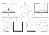
- FIG. 1is a simplified illustration of a data protection system 100 , in accordance with an embodiment of the present invention. Shown in FIG. 1 are two sites; Site I, which is a production site, on the right, and Site II, which is a backup site, on the left. Under normal operation the production site is the source side of system 100 , and the backup site is the target side of the system. The backup site is responsible for replicating production site data. Additionally, the backup site enables rollback of Site I data to an earlier pointing time, which may be used in the event of data corruption of a disaster, or alternatively in order to view or to access data from an earlier point in time.
- a failovermay be performed in the event of a disaster at the production site, or for other reasons.
- Site I or Site IIbehaves as a production site for a portion of stored data, and behaves simultaneously as a backup site for another portion of stored data.
- a portion of stored datais replicated to a backup site, and another portion is not.
- the production site and the backup sitemay be remote from one another, or they may both be situated at a common site, local to one another.
- Local data protectionhas the advantage of minimizing data lag between target and source, and remote data protection has the advantage is being robust in the event that a disaster occurs at the source side.
- the source and target sidescommunicate via a wide area network (WAN) 128 , although other types of networks are also adaptable for use with the present invention.
- WANwide area network
- each side of system 100includes three major components coupled via a storage area network (SAN); namely, (i) a storage system, (ii) a host computer, and (iii) a data protection appliance (DPA).
- SANstorage area network
- the source side SANincludes a source host computer 104 , a source storage system 108 , and a source DPA 112 .
- the target side SANincludes a target host computer 116 , a target storage system 120 , and a target DPA 124 .
- a SANincludes one or more devices, referred to as “nodes”.
- a node in a SANmay be an “initiator” or a “target”, or both.
- An initiator nodeis a device that is able to initiate requests to one or more other devices; and a target node is a device that is able to reply to requests, such as SCSI commands, sent by an initiator node.
- a SANmay also include network switches, such as fiber channel switches.
- the communication links between each host computer and its corresponding storage systemmay be any appropriate medium suitable for data transfer, such as fiber communication channel links.
- the hostcommunicates with its corresponding storage system using small computer system interface (SCSI) commands.
- SCSIsmall computer system interface
- System 100includes source storage system 108 and target storage system 120 .
- Each storage systemincludes physical storage units for storing data, such as disks or arrays of disks.
- storage systems 108 and 120are target nodes.
- storage system 108exposes one or more logical units (LU) to which commands are issued.
- LUlogical units
- storage systems 108 and 120are SAN entities that provide multiple logical units for access by multiple SAN initiators.
- Logical unitsare a logical entity provided by a storage system, for accessing data stored in the storage system.
- a logical unitis identified by a unique logical unit number (LUN).
- LUNunique logical unit number
- storage system 108exposes a logical unit 136 , designated as LU A
- storage system 120exposes a logical unit 156 , designated as LU B.
- LU Bis used for replicating LU A. As such, LU B is generated as a copy of LU A. In one embodiment, LU B is configured so that its size is identical to the size of LU A. Thus for LU A, storage system 120 serves as a backup for source side storage system 108 . Alternatively, as mentioned hereinabove, some logical units of storage system 120 may be used to back up logical units of storage system 108 , and other logical units of storage system 120 may be used for other purposes.
- System 100includes a source side host computer 104 and a target side host computer 116 .
- a host computermay be one computer, or a plurality of computers, or a network of distributed computers, each computer may include inter alia a conventional CPU, volatile and non-volatile memory, a data bus, an I/O interface, a display interface and a network interface.
- a host computerruns at least one data processing application, such as a database application and an e-mail server.
- an operating system of a host computercreates a host device for each logical unit exposed by a storage system in the host computer SAN.
- a host deviceis a logical entity in a host computer, through which a host computer may access a logical unit.
- host device 104identifies LU A and generates a corresponding host device 140 , designated as Device A, through which it can access LU A.
- host computer 116identifies LU B and generates a corresponding device 160 , designated as Device B.
- host computer 104is a SAN initiator that issues I/O requests (write/read operations) through host device 140 to LU A using, for example, SCSI commands. Such requests are generally transmitted to LU A with an address that includes a specific device identifier, an offset within the device, and a data size. Offsets are generally aligned to 512 byte blocks.
- the average size of a write operation issued by host computer 104may be, for example, 10 kilobytes (KB); i.e., 20 blocks. For an I/O rate of 50 megabytes (MB) per second, this corresponds to approximately 5,000 write transactions per second.
- System 100includes two data protection appliances, a source side DPA 112 and a target side DPA 124 .
- a DPAperforms various data protection services, such as data replication of a storage system, and journaling of I/O requests issued by a host computer to source side storage system data.
- data protection servicessuch as data replication of a storage system, and journaling of I/O requests issued by a host computer to source side storage system data.
- a DPAmay also enable rollback of data to an earlier point in time, and processing of rolled back data at the target site.
- Each DPA 112 and 124is a computer that includes inter alia one or more conventional CPUs and internal memory.
- each DPAis a cluster of such computers.
- Use of a clusterensures that if a DPA computer is down, then the DPA functionality switches over to another computer.
- the DPA computers within a DPA clustercommunicate with one another using at least one communication link suitable for data transfer via fiber channel or IP based protocols, or such other transfer protocol.
- One computer from the DPA clusterserves as the DPA leader.
- the DPA cluster leadercoordinates between the computers in the cluster, and may also perform other tasks that require coordination between the computers, such as load balancing.
- DPA 112 and DPA 124are standalone devices integrated within a SAN.
- each of DPA 112 and DPA 124may be integrated into storage system 108 and storage system 120 , respectively, or integrated into host computer 104 and host computer 116 , respectively.
- Both DPAscommunicate with their respective host computers through communication lines such as fiber channels using, for example, SCSI commands.
- DPAs 112 and 124are configured to act as initiators in the SAN; i.e., they can issue I/O requests using, for example, SCSI commands, to access logical units on their respective storage systems.
- DPA 112 and DPA 124are also configured with the necessary functionality to act as targets; i.e., to reply to I/O requests, such as SCSI commands, issued by other initiators in the SAN, including inter alia their respective host computers 104 and 116 .
- targetsi.e., to reply to I/O requests, such as SCSI commands, issued by other initiators in the SAN, including inter alia their respective host computers 104 and 116 .
- DPA 112 and DPA 124may dynamically expose or remove one or more logical units.
- Site I and Site IImay each behave simultaneously as a production site and a backup site for different logical units.
- DPA 112 and DPA 124may each behave as a source DPA for some logical units and as a target DPA for other logical units, at the same time.
- host computer 104 and host computer 116include protection agents 144 and 164 , respectively.
- Protection agents 144 and 164intercept SCSI commands issued by their respective host computers, via host devices to logical units that are accessible to the host computers.
- a data protection agentmay act on an intercepted SCSI commands issued to a logical unit, in one of the following ways:
- a protection agentmay handle different SCSI commands, differently, according to the type of the command. For example, a SCSI command inquiring about the size of a certain logical unit may be sent directly to that logical unit, while a SCSI write command may be split and sent first to a DPA associated with the agent.
- a protection agentmay also change its behavior for handling SCSI commands, for example as a result of an instruction received from the DPA.
- the behavior of a protection agent for a certain host devicegenerally corresponds to the behavior of its associated DPA with respect to the logical unit of the host device.
- the associated protection agentsplits I/O requests issued by a host computer to the host device corresponding to that logical unit.
- the associated protection agentfails I/O requests issued by host computer to the host device corresponding to that logical unit.
- Protection agentsmay use any protocol suitable for data transfer within a SAN, such as fiber channel, or SCSI over fiber channel.
- the communicationmay be direct, or via a logical unit exposed by the DPA.
- protection agentscommunicate with their respective DPAs by sending SCSI commands over fiber channel.
- protection agents 144 and 164are drivers located in their respective host computers 104 and 116 .
- a protection agentmay also be located in a fiber channel switch, or in any other device situated in a data path between a host computer and a storage system.
- the protection agentmay be installed as part of the storage array IO stack.
- the DPAmay be installed as a virtual appliance or as a set of processes inside the storage array.
- DPA 112acts as a source site DPA for LU A.
- protection agent 144is configured to act as a source side protection agent; i.e., as a splitter for host device A.
- protection agent 144replicates SCSI I/O requests.
- a replicated SCSI I/O requestis sent to DPA 112 .
- protection agent 144After receiving an acknowledgement from DPA 124 , protection agent 144 then sends the SCSI I/O request to LU A. Only after receiving a second acknowledgement from storage system 108 may host computer 104 initiate another I/O request.
- DPA 112When DPA 112 receives a replicated SCSI write request from data protection agent 144 , DPA 112 transmits certain I/O information characterizing the write request, packaged as a “write transaction”, over WAN 128 to DPA 124 on the target side, for journaling and for incorporation within target storage system 120 .
- DPA 112may send its write transactions to DPA 124 using a variety of modes of transmission, including inter alia (i) a synchronous mode, (ii) an asynchronous mode, and (iii) a snapshot mode.
- DPA 112sends each write transaction to DPA 124 , receives back an acknowledgement from DPA 124 , and in turns sends an acknowledgement back to protection agent 144 .
- Protection agent 144waits until receipt of such acknowledgement before sending the SCSI write request to LU A.
- DPA 112sends an acknowledgement to protection agent 144 upon receipt of each I/O request, before receiving an acknowledgement back from DPA 124 .
- DPA 112receives several I/O requests and combines them into an aggregate “snapshot” of all write activity performed in the multiple I/O requests, and sends the snapshot to DPA 124 , for journaling and for incorporation in target storage system 120 .
- DPA 112also sends an acknowledgement to protection agent 144 upon receipt of each I/O request, before receiving an acknowledgement back from DPA 124 .
- DPA 124While in production mode, DPA 124 receives replicated data of LU A from DPA 112 , and performs journaling and writing to storage system 120 . When applying write operations to storage system 120 , DPA 124 acts as an initiator, and sends SCSI commands to LU B.
- DPA 124undoes the write transactions in the journal, so as to restore storage system 120 to the state it was at, at an earlier time.
- LU Bis used as a backup of LU A.
- host computer 116should not be sending I/O requests to LU B.
- protection agent 164acts as a target site protection agent for host Device B and fails I/O requests sent from host computer 116 to LU B through host Device B.
- target storage system 120exposes a logical unit 176 , referred to as a “journal LU”, for maintaining a history of write transactions made to LU B, referred to as a “journal”.
- journal LU 176may be striped over several logical units, or may reside within all of or a portion of another logical unit.
- DPA 124includes a journal processor 180 for managing the journal.
- Journal processor 180functions generally to manage the journal entries of LU B. Specifically, journal processor 180 ( i ) enters write transactions received by DPA 124 from DPA 112 into the journal, by writing them into the journal LU, (ii) applies the journal transactions to LU B, and (iii) updates the journal entries in the journal LU with undo information and removes already-applied transactions from the journal. As described below, with reference to FIGS. 2 and 3A-3D , journal entries include four streams, two of which are written when write transaction are entered into the journal, and two of which are written when write transaction are applied and removed from the journal.
- FIG. 2is a simplified illustration of a write transaction 200 for a journal, in accordance with an embodiment of the present invention.
- the journalmay be used to provide an adaptor for access to storage 120 at the state it was in at any specified point in time. Since the journal contains the “undo” information necessary to rollback storage system 120 , data that was stored in specific memory locations at the specified point in time may be obtained by undoing write transactions that occurred subsequent to such point in time.
- Write transaction 200generally includes the following fields:
- time stampwhich is the date & time at which the transaction was received by source side DPA 112 ;
- a write sizewhich is the size of the data block
- journal LU 176a location in journal LU 176 where the data is entered
- Write transaction 200is transmitted from source side DPA 112 to target side DPA 124 .
- DPA 124records the write transaction 200 in four streams.
- a first streamreferred to as a DO stream, includes new data for writing in LU B.
- a second streamreferred to as an DO METADATA stream, includes metadata for the write transaction, such as an identifier, a date & time, a write size, a beginning address in LU B for writing the new data in, and a pointer to the offset in the do stream where the corresponding data is located.
- a third streamreferred to as an UNDO stream
- a fourth streamreferred to as an UNDO METADATA
- an identifiera date & time
- a write sizea beginning address in LU B where data was to be overwritten
- each of the four streamsholds a plurality of write transaction data.
- write transactionsare received dynamically by target DPA 124 , they are recorded at the end of the DO stream and the end of the DO METADATA stream, prior to committing the transaction.
- the various write transactionsare applied to LU B, prior to writing the new DO data into addresses within the storage system, the older data currently located in such addresses is recorded into the UNDO stream.
- journal entryBy recording old data, a journal entry can be used to “undo” a write transaction.
- old datais read from the UNDO stream in a reverse order, from the most recent data to the oldest data, for writing into addresses within LU B. Prior to writing the UNDO data into these addresses, the newer data residing in such addresses is recorded in the DO stream.
- the journal LUis partitioned into segments with a pre-defined size, such as 1 MB segments, with each segment identified by a counter.
- the collection of such segmentsforms a segment pool for the four journaling streams described hereinabove.
- Each such streamis structured as an ordered list of segments, into which the stream data is written, and includes two pointers—a beginning pointer that points to the first segment in the list and an end pointer that points to the last segment in the list.
- write transaction datais appended to the stream either at the end, for a forward direction, or at the beginning, for a backward direction.
- DPA 124As each write transaction is received by DPA 124 , its size is checked to determine if it can fit within available segments. If not, then one or more segments are chosen from the segment pool and appended to the stream's ordered list of segments.
- DO datais written into the DO stream, and the pointer to the appropriate first or last segment is updated. Freeing of segments in the ordered list is performed by simply changing the beginning or the end pointer. Freed segments are returned to the segment pool for re-use.
- a journalmay be made of any number of streams including less than or more than 5 streams. Often, based on the speed of the journaling and whether the back-up is synchronous or a synchronous a fewer or greater number of streams may be used.
- FIG. 3 and FIG. 4depict systems and processes for initializing a backup snapshot on deduplicated storage consistent with an embodiment of the present disclosure.
- initial backup snapshotmay represent the earliest point-in-time backup that may be restored.
- journal files and/or new backupsmay be updated and/or synthesized to provide continuous protection.
- the initial backup snapshotmay be created by streaming IO's from a storage system scan to a data protection appliance, or by taking an initial snapshot of the storage system and transmitting the entire snapshot to deduplicated storage.
- FIG. 3depicts a system for creating an initial backup snapshot by scanning a source storage system and streaming IO's to the deduplicated storage.
- Data protection application 300may comprise journal processor 302 , and may be in communication with deduplicated storage 304 .
- deduplicated storage 304may be target side storage residing at a backup site.
- Data protection appliance 300may be similar to data protection appliance 112 and/or 124 , and may be responsible for streaming IO's to deduplicated storage 304 .
- a source storage systemmay be scanned and individual offsets may be streamed to data protection appliance 300 .
- the offsets streamed from the scanned systemmay be referred to as initialization IO's, and may be streamed sequentially to data protection appliance 300 .
- the scanned systemmay comprise offsets 0, 1, 2, and 3, comprising data A, B, C, and D.
- the initial scanmay start at the beginning of the system, and transmit offset 0, followed by offset 1, et seq.
- journal processor 302may identify the offset data and metadata, and may stream the IO's to metadata journal 306 and/or data journal 308 residing on deduplicated storage 304 .
- Data journal 308may comprise data stored within an offset, and metadata 306 may include metadata associated with that offset. Metadata could include, for example, an offset identifier, size, write time, and device ID. These journals may then be used to synthesize a backup snapshot on deduplicated storage 304 , as discussed below.
- a scanned storage systemmay operate in a live environment.
- applicationsmay be writing to the storage concurrently with the scan process. If an application writes to a location that has already been streamed, the journal files and ultimately the synthesized snapshot may be out of date.
- application IO'smay be streamed concurrently with the initialization IO's if the application IO's are to an offset that has already been scanned. For example, consider Table 1:
- Time Offset t0 t1 t2 t3 0A A′ 1 B B′ 2 C 3 D D′ Table 1 depicts four different offsets, denoted as 0, 1, 2, and 3, and four times, t0, t1, t2, and t3. Letters A, B, C, and D may represent the data stored at the offsets. Time t0 may represent the offsets as they exist when the scan begins. These offsets may be streamed to data protection appliance 300 sequentially from 0 to 3. At time t1, however, the data at offset 1 is modified by an application from B to B′. Similarly, at t2 the data at offset 3 changes from D to D′, and at t3 the data at offset 0 changes from A to A′.
- offset metadata journal entries 310 and offset data journal entries 312depict the state of metadata journal 306 and data journal 308 after the initial scan is complete. While there are only four offsets on the scanned storage system, there are six entries in the journal because the data in offset 0 and 1 was modified by an application after they were scanned. They each therefore have two entries: B and B′. Segment D was modified after the scan began, but before it was reached. Segment D therefore only has one entry: D′.
- Metadata journal entries 310 and data journal entries 312may include all of the data necessary to synthesize a backup snapshot of the scanned storage system.
- Data journal entries 312may contain the actual data from the storage system: A, B, B′ C, A′ and D′. Note that data D is not in the data journal 308 since it was modified on the storage system before its offset was scanned and transmitted.
- Metadata journal entries 310may include metadata about the offsets.
- metadata journal entries 310may include an offset identifier, offset length, and write time, and volume/device ID.
- metadata journal entriesmay include the entries shown in Table 2:
- Deduplicated storagemay use metadata journal 306 and data journal 308 to synthesize initial backup snapshot 314 .
- metadata journal 306may be queried to identify the most recent data associated with each offset.
- the datamay be retrieved from journal data file 308 and synthesized into backup snapshot 314 .
- synthesizing the backup snapshotmay comprise creating and/or copying pointers rather than copying entire data blocks. This could be, for example, using a product such as EMU® DataDomain® BoostTM
- data journal 308includes data A, B, B′, C, A′, and D′.
- A′ and B′are the result of application IO's occurring during the scan process, and therefore represent the present state of offsets 0 and 1.
- deduplicated storagemay therefore retrieve A′, B′, C, and D′ from the data journal 308 and synthesize them together.
- journal entries 310 and 312may no longer be needed. In an embodiment, they may be removed from deduplicated storage 304 in order to conserve space. Alternatively, they may remain in the journals.
- the system of FIG. 4includes data protection appliance 400 , journal processor 402 , and deduplicated storage 404 . These elements may be substantially similar to those discussed in reference to FIG. 3 .
- Deduplicated storage 404may include backup snapshot 414 , metadata journal file 406 , and data journal file 408 .
- backup snapshot file 414is synthesized in a manner substantially similar to backup snapshot 314 , and may be created using metadata journal entries 410 and data journal entries 412 .
- data protection appliance 400may receive and stream application IO's to deduplicated storage system 404 on a continuous basis, even after initial backup snapshot 414 is synthesized. Streaming the application IO's allows the backups on deduplicated storage 404 to remain up-to-date, without needing to perform additional backups of large datasets. This may reduce network traffic, reduce workloads, and conserve space on deduplicated storage 404 .
- new metadata entries 411 and new data journal entries 413represent IO's made after initial backup snapshot 414 was synthesized. These entries may be written to metadata journal 406 and data journal 408 , as shown in FIG. 4 , or they may be written to separate journal files. In FIG. 4 , data A′ and C were modified on the source storage device, and the journal entries therefore comprise A′′ and C′.
- new backup snapshotsmay be synthesized from a previous backup snapshot and new journal entries.
- second backup snapshot 416may be synthesized from initial backup snapshot 414 , new metadata journal entries 411 , and new data journal entries 413 .
- Second backup snapshot 416may be used to restore source storage system up to the point-in-time the last journal entry was received.
- backup snapshot 416represents a backup of the source storage system at a later timestamp than initial backup snapshot 414 .
- synthesizing second backup journal entry 416may be substantially similar to synthesizing the initial backup snapshot 414 . Rather than synthesizing all of the data from data journal 408 , however, unchanged data may be synthesized from initial backup snapshot 414 . In an embodiment, this synthesis may comprise copying and/or creating a data pointer. For example, in FIG. 4 the solid arrows between initial backup snapshot 414 and second backup snapshot 416 represent unchanged data that is common between the two. In this case, only B′ and D′ remain unchanged. The dashed arrows represent new or changed data that needs to be synthesized into second backup snapshot 416 . In FIG. 4 , A′ is changed to A′′, C is change to C′. Synthesizing the data into second backup snapshot 416 therefore results in A′′, B′, C′, D′.
- second backup snapshot 416may be synthesized entirely from journal entries. Rather than synthesizing unchanged data from initial backup 414 , deduplicated storage 404 may retrieve the unchanged data from data journal entries 412 . For example, B′ and D′ may be synthesized from data journal entries 412 rather than from initial backup snapshot 414 .
- Additional backup snapshotsmay be created periodically or on demand.
- a user policymay specify that new snapshots should be created every week.
- a usermay be preparing to perform some risky operations on the source storage system, and may demand that a snapshot be created in case something goes wrong. These policies may be maintained and applied using data protection appliance 400 , deduplicated storage 404 , and/or an external system.
- journal entriesmay be application IO's which are continuously streamed to a data protection appliance. While these snapshots may provide additional data protection, they may only allow data that exists in the snapshots to be recovered. Combining snapshots and journal files may, however, allow any point-in-time recovery.
- a replicated storage, deduplicated storage and/or data protection applianceprovides the ability to perform recovery from previously stored data.
- a replicated storage, deduplicated storage and/or data protection applianceis needed when the primary data is corrupted due to an event, such as a malicious event or a non-intended event.
- an eventsuch as a malicious event or a non-intended event.
- a replicated storage, deduplication storage and/or data protection appliancecan protect from an accidental deletion of a table from a database or a virus attack that corrupts files.
- a replicated storage, deduplicated storage and/or data protection applianceallows the user to choose a point in time (PiT) that is earlier than the corrupted event which is present in the appliance's system and restore this PiT back to the primary storage recovering the data to a non-corrupt state.
- a replicated storage, deduplicated storage and/or data protection appliancecreates a journal that includes all of the changes that happened throughout the use of storage managed by the system.
- a replicated storage, deduplicated storage and/or data protection applianceuses a journal to create a virtual image to access a snapshot of a device at a specified time.
- DO and UNDO information of a journalcan waste resources than necessary during recovery operations.
- the data storage industrywould benefit from being able to efficiently access a snapshot of a device at a specified time.
- the current disclosuremay enable a replicated storage, deduplicated storage and/or data protection appliance to support virtual image access on demand.
- the current disclosuremay enable a replicated storage, deduplicated storage and/or data protection appliance to efficiently create virtual images of a device at a point in time.
- the current disclosuremay enable a replicated storage, deduplicated storage and/or data protection appliance build a difference table which may enable the replicated storage, deduplicated storage and/or data protection appliance to create a virtual image of a device.
- a replicated storage, deduplicated storage and/or data protection appliancemay be referred to as a system and/or data storage system.
- a replicated storage systemmay be enabled to include the functionality of a deduplicated storage system
- a systemmay be enabled to create a virtual image using two snapshots and a difference journal.
- a systemmay create snapshots on a periodic and/or non-periodic basis. In some embodiments, periodically may include hourly, daily, monthly, and/or other intervals.
- a systemmay be enabled to create a difference journal which may be enabled to describe differences between a first snapshot and a second snapshot.
- a difference journalmay be more efficient than a full journal (including DO and UNDO information) as the difference journal may not include changes that already appear in either a first snapshot or second snapshot as the difference journal.
- reducing the size of a journal required to create a virtual imagemay increase the storage efficiency of the system and the speed at which the system may be enabled to create the virtual image.
- a difference journalmay include metadata from the full journal data and may include data for locations that have been written between a first snapshot and a second snapshot.
- a difference journalmay include data from the full journal data that may not already been included in the first snapshot or the second snapshot.
- a systemmay be enabled to create a difference journal from a full journal once two or more snapshots are created. For example, in an embodiment, a system may analyze DO information from a full journal between a first and second snapshot. In this embodiment, the DO information contains data changes for four offsets and looks like Table 3 below:
- the DO informationcontains information regarding changes to the first snapshot at each timestamp specified within the DO information.
- Offset 2was changed to E.
- Offset 4was changed to G.
- Offset 4was changed to H.
- the systemmigrates changes from the DO information to the Difference Journal if the DO information shows more than one data change. As shown in Table 3, Offsets 2 and 4 have changed at least two times. Further, the system does not migrate the last data change for each offset in the DO information to the Difference Journal as that information is contained with the second snapshot.
- the completed difference table based on Table 3should like table 4 below:
- a systemmay be tasked with creating periodic snapshots of storage managed by the system.
- the systemmay continually create a full journal which may include DO and UNDO information.
- the systemmay convert a full journal referencing data between, and including, the first and second snapshots into a difference journal.
- a systemmay remove the full journal associated with the difference journal.
- the systemmay convert the full journal into a difference journal for data between, and including, the most recent snapshot and the snapshot prior to the most recent snapshot.
- a systemmay receive requests to create a virtual image at a point in time. In certain embodiments, a system may determine which snapshots and/or difference journals may be applicable to the request for a virtual image at a specified point in time.
- a systemreceives a request to create a virtual image at a specified point in time.
- a systemdetermines that snapshot S 1 , snapshot S 2 , and difference Journal D 1 are relevant to the request.
- the systemcreates a structure that contains references to the most recent information related to data locations that have changed between snapshot S 1 and the requested point in time. The most recent information related to data locations may be located within the difference journal or within snapshot S 2 .
- the systemis enabled to respond to the request using snapshot S 1 and the structure.
- a read from the created virtual imagemay be retrieved from snapshot S 1 , the difference journal by using the structure, or snapshot S 2 by using the structure.
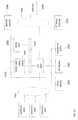
- FIG. 5is a simplified illustration of a system, in accordance with an embodiment of the present disclosure.
- System 500includes primary data storage 510 , deduplicated data storage 515 , and Data Protection Appliances (DPA) 535 , 545 .
- Host 505uses source Protection Agent (PA) 530 to communicate with Primary Data Storage 510 and DPA 535 .
- PAsource Protection Agent
- Source PA 530splits data I/Os from Host 505 to production LU 532 and to DPA 535 .
- DPA 535forwards the received data I/O to DPA 545 using WAN 525 .
- DPA 545is enabled to use journal processor 550 to create and/or update LU File 555 and Journal LU 560 residing on deduplicated data storage 515 .
- Journal LU 560includes Journal Data 565 and Difference Journal 570 .
- Journal Processor 550is enabled to create snapshots of LU File 555 .
- Snapshot 575is a snapshot of LU File 555 at time t 0 .
- Snapshot 580is a snapshot of LU File 555 at time t 1 .
- Snapshot 585is enabled to be the next snapshot taken of LU File 555 at time t 3 .
- Journal Processor 550is enabled to convert portions of Full Journal 565 relating to data between, and including, snapshot 580 and snapshot 585 , to part of difference journal 570 .
- FIG. 6is a simplified illustration of the system as described in FIG. 5 creating a virtual image, in accordance with an embodiment of the present disclosure.
- Journal Processor 550creates virtual image data structure 610 and populates virtual image data structure 610 with references to data changed since Snapshot 575 .
- virtual image data structure 610includes references to offset 2 in Difference Journal 570 and offset 4 in Snapshot 580 which enables system 500 to create image 615 .
- FIG. 7is an alternate simplified illustration of the system as described in FIG. 5 creating a virtual image, in accordance with an embodiment of the present disclosure.
- Journal Processor 550creates virtual image data structure 610 and populates virtual image data structure 610 with references to data changed since Snapshot 575 .
- virtual image data structure 705includes references to offset 2 in Difference Journal 570 enables system 500 to create image 710 .
- FIG. 8is a simplified flowchart of a method of providing access to a virtual image on a system as described in FIG. 5 , in accordance with an embodiment of the present disclosure.
- System 500includes primary data storage 510 , deduplicated data storage 515 , and Data Protection Appliances (DPA) 535 , 545 .
- Host 505uses source Protection Agent (PA) 530 to communicate with Primary Data Storage 510 and DPA 535 .
- System 500receives a request at DPA 535 to create an image at a point in time (Step 800 ).
- DPA 535forwards the request to DPA 545 through WAN 525 .
- Journal 550creates a virtual image structure based for the requested point in time based off difference journal 570 (Step 810 ). Journal Processor 550 synthesize the requested virtual image using snapshot 575 and the virtual image structure (Step 820 ), which contains references to data changed since snapshot 575 . System 500 provides access to the virtual image through primary data storage 510 or deduplicated data storage 515 (Step 830 ).
- FIG. 9is a simplified flowchart of a method of creating a difference journal using the system as described in FIG. 5 , in accordance with an embodiment of the present disclosure.
- System 500includes primary data storage 510 , deduplicated data storage 515 , and Data Protection Appliances (DPA) 535 , 545 .
- DPA 545uses Journal processor 550 is enabled to periodically create snapshots.
- Journal processor 550has created snapshot 575 and snapshot 580 .
- Journal Processor 550creates snapshot 585 (Step 900 ) and analyzes Journal LU 560 to determine whether a difference journal should be created (Step 910 ).
- Journal Processor 550determines that a difference journal should be created and creates difference journal 570 based on DO information in Full Journal 565 (Step 920 ). Upon completion of difference Journal 570 , journal processor 550 removes portions of full journal 565 pertaining to data changes between snapshot 585 and snapshot 580 (Step 930 ). At this point, System 500 is enabled to process virtual image requests for images between snapshot 580 and snapshot 585 .
- the methods and apparatus of this inventionmay take the form, at least partially, of program code (i.e., instructions) embodied in tangible non-transitory media, such as floppy diskettes, CD-ROMs, hard drives, random access or read only-memory, or any other machine-readable storage medium.
- program codei.e., instructions
- tangible non-transitory mediasuch as floppy diskettes, CD-ROMs, hard drives, random access or read only-memory, or any other machine-readable storage medium.
- FIG. 10is a block diagram illustrating an apparatus, such as a computer 1010 in a network 1000 , which may utilize the techniques described herein according to an example embodiment of the present invention.
- the computer 1010may include one or more I/O ports 1002 , a processor 1003 , and memory 1004 , all of which may be connected by an interconnect 1025 , such as a bus.
- Processor 1003may include program logic 1005 .
- the I/O port 1002may provide connectivity to memory media 1083 , I/O devices 1085 , and drives 1087 , such as magnetic or optical drives.
- the program codeWhen the program code is loaded into memory 1004 and executed by the computer 1010 , the machine becomes an apparatus for practicing the invention.
- the program codeWhen implemented on one or more general-purpose processors 1003 , the program code combines with such a processor to provide a unique apparatus that operates analogously to specific logic circuits. As such, a general purpose digital machine can be transformed into a special purpose digital machine.
- FIG. 11is a block diagram illustrating a method embodied on a computer readable storage medium 1160 that may utilize the techniques described herein according to an example embodiment of the present invention.
- FIG. 11shows Program Logic 1155 embodied on a computer-readable medium 1160 as shown, and wherein the Logic is encoded in computer-executable code configured for carrying out the methods of this invention and thereby forming a Computer Program Product 1100 .
- Program Logic 1155may be the same logic 1005 on memory 1004 loaded on processor 1003 in FIG. 10 .
- the program logicmay be embodied in software modules, as modules, as hardware modules, or on virtual machines.
- the logic for carrying out the methodmay be embodied as part of the aforementioned system, which is useful for carrying out a method described with reference to embodiments shown in, for example, FIGS. 1-11 .
- the inventionis described as embodied in a specific configuration and using special logical arrangements, but one skilled in the art will appreciate that the device is not limited to the specific configuration but rather only by the claims included with this specification.
Landscapes
- Engineering & Computer Science (AREA)
- Theoretical Computer Science (AREA)
- Physics & Mathematics (AREA)
- General Engineering & Computer Science (AREA)
- General Physics & Mathematics (AREA)
- Quality & Reliability (AREA)
- Human Computer Interaction (AREA)
- Information Retrieval, Db Structures And Fs Structures Therefor (AREA)
Abstract
Description
| Time | |||
| Offset | t0 | t1 | t2 | t3 |
| 0 | A | A′ | ||
| 1 | B | B′ | ||
| 2 | C | |||
| 3 | D | D′ | ||
Table 1 depicts four different offsets, denoted as 0, 1, 2, and 3, and four times, t0, t1, t2, and t3. Letters A, B, C, and D may represent the data stored at the offsets. Time t0 may represent the offsets as they exist when the scan begins. These offsets may be streamed to
| 0. Vol A, offset = 0; size = 8 kb; time = | ||
| 1. Vol A, offset = 8 kb; size = 8 kb; time = | ||
| 2. Vol A, offset = 8 kb; size = 8 kb; time = | ||
| 3. Vol A, offset = 16 kb; size = 8 kb; time = | ||
| 4. Vol A, offset = 0; size = 8 kb; time = | ||
| 5. Vol A, offset = 24 kb; size = 8 kb; time = t2 | ||
Table 2's metadata entries may correspond to the states shown in Table 1. The offset at location may be offset 0, the offset at 8 kb may be offset 1, the offset at 16 kb may be offset 2, and the offset at 24 kb may be offset 3. The subscript of each
| 1 | 2 | 3 | 4 | 5 | |||
| Offset | 2 | 4 | 4 | 4 | 2 | ||
| Data | E | G | H | I | F | ||
In this embodiment, the DO information contains information regarding changes to the first snapshot at each timestamp specified within the DO information. At Time=1, Offset 2 was changed to E. At Time=2, Offset 4 was changed to G. At Time=3, Offset 4 was changed to H. At Time=4, Offset 4 was changed to I and at time=5, offset 2 was changed to F. The system migrates changes from the DO information to the Difference Journal if the DO information shows more than one data change. As shown in Table 3,
| 1 | 2 | 3 | 4 | 5 | |||
| Offset | 2 | 4 | 4 | 4 | 2 | ||
| Data | E | G | H | ||||
As shown in table 4, the difference journal does not store data for the changes at Time=4 and Time=5 as described above.
Claims (12)
Priority Applications (2)
| Application Number | Priority Date | Filing Date | Title |
|---|---|---|---|
| US14/670,593US9940205B2 (en) | 2015-03-27 | 2015-03-27 | Virtual point in time access between snapshots |
| CN201610180426.9ACN106021016A (en) | 2015-03-27 | 2016-03-25 | Virtual point in time access between snapshots |
Applications Claiming Priority (1)
| Application Number | Priority Date | Filing Date | Title |
|---|---|---|---|
| US14/670,593US9940205B2 (en) | 2015-03-27 | 2015-03-27 | Virtual point in time access between snapshots |
Publications (2)
| Publication Number | Publication Date |
|---|---|
| US20160283329A1 US20160283329A1 (en) | 2016-09-29 |
| US9940205B2true US9940205B2 (en) | 2018-04-10 |
Family
ID=56975377
Family Applications (1)
| Application Number | Title | Priority Date | Filing Date |
|---|---|---|---|
| US14/670,593ActiveUS9940205B2 (en) | 2015-03-27 | 2015-03-27 | Virtual point in time access between snapshots |
Country Status (2)
| Country | Link |
|---|---|
| US (1) | US9940205B2 (en) |
| CN (1) | CN106021016A (en) |
Cited By (35)
| Publication number | Priority date | Publication date | Assignee | Title |
|---|---|---|---|---|
| US10078459B1 (en) | 2016-09-26 | 2018-09-18 | EMC IP Holding Company LLC | Ransomware detection using I/O patterns |
| US10108356B1 (en) | 2016-03-25 | 2018-10-23 | EMC IP Holding Company LLC | Determining data to store in retention storage |
| US10133874B1 (en) | 2015-12-28 | 2018-11-20 | EMC IP Holding Company LLC | Performing snapshot replication on a storage system not configured to support snapshot replication |
| US10140039B1 (en) | 2016-12-15 | 2018-11-27 | EMC IP Holding Company LLC | I/O alignment for continuous replication in a storage system |
| US10223023B1 (en) | 2016-09-26 | 2019-03-05 | EMC IP Holding Company LLC | Bandwidth reduction for multi-level data replication |
| US10229006B1 (en) | 2015-12-28 | 2019-03-12 | EMC IP Holding Company LLC | Providing continuous data protection on a storage array configured to generate snapshots |
| US10235087B1 (en) | 2016-03-30 | 2019-03-19 | EMC IP Holding Company LLC | Distributing journal data over multiple journals |
| US10235247B1 (en) | 2016-09-26 | 2019-03-19 | EMC IP Holding Company LLC | Compressing memory snapshots |
| US10235060B1 (en) | 2016-04-14 | 2019-03-19 | EMC IP Holding Company, LLC | Multilevel snapshot replication for hot and cold regions of a storage system |
| US10235061B1 (en) | 2016-09-26 | 2019-03-19 | EMC IP Holding Company LLC | Granular virtual machine snapshots |
| US10235088B1 (en) | 2016-03-30 | 2019-03-19 | EMC IP Holding Company LLC | Global replication policy for multi-copy replication |
| US10235145B1 (en) | 2012-09-13 | 2019-03-19 | Emc International Company | Distributed scale-out replication |
| US10324798B1 (en) | 2014-09-25 | 2019-06-18 | EMC IP Holding Company LLC | Restoring active areas of a logical unit |
| US10366011B1 (en) | 2018-05-03 | 2019-07-30 | EMC IP Holding Company LLC | Content-based deduplicated storage having multilevel data cache |
| US10409629B1 (en) | 2016-09-26 | 2019-09-10 | EMC IP Holding Company LLC | Automated host data protection configuration |
| US10409787B1 (en) | 2015-12-22 | 2019-09-10 | EMC IP Holding Company LLC | Database migration |
| US10409986B1 (en) | 2016-09-26 | 2019-09-10 | EMC IP Holding Company LLC | Ransomware detection in a continuous data protection environment |
| US10423634B1 (en) | 2016-12-27 | 2019-09-24 | EMC IP Holding Company LLC | Temporal queries on secondary storage |
| US10437783B1 (en) | 2014-09-25 | 2019-10-08 | EMC IP Holding Company LLC | Recover storage array using remote deduplication device |
| US10467102B1 (en) | 2016-12-15 | 2019-11-05 | EMC IP Holding Company LLC | I/O score-based hybrid replication in a storage system |
| US10489321B1 (en) | 2018-07-31 | 2019-11-26 | EMC IP Holding Company LLC | Performance improvement for an active-active distributed non-ALUA system with address ownerships |
| US10496487B1 (en) | 2014-12-03 | 2019-12-03 | EMC IP Holding Company LLC | Storing snapshot changes with snapshots |
| US10579282B1 (en) | 2016-03-30 | 2020-03-03 | EMC IP Holding Company LLC | Distributed copy in multi-copy replication where offset and size of I/O requests to replication site is half offset and size of I/O request to production volume |
| US10592166B2 (en) | 2018-08-01 | 2020-03-17 | EMC IP Holding Company LLC | Fast input/output in a content-addressable storage architecture with paged metadata |
| US10628268B1 (en) | 2016-12-15 | 2020-04-21 | EMC IP Holding Company LLC | Proof of data replication consistency using blockchain |
| US10713221B2 (en) | 2018-07-30 | 2020-07-14 | EMC IP Holding Company LLC | Dual layer deduplication for a file system running over a deduplicated block storage |
| US10747667B2 (en) | 2018-11-02 | 2020-08-18 | EMC IP Holding Company LLC | Memory management of multi-level metadata cache for content-based deduplicated storage |
| US10747606B1 (en) | 2016-12-21 | 2020-08-18 | EMC IP Holding Company LLC | Risk based analysis of adverse event impact on system availability |
| US10776211B1 (en) | 2016-12-27 | 2020-09-15 | EMC IP Holding Company LLC | Methods, systems, and apparatuses to update point in time journal using map reduce to create a highly parallel update |
| US10853181B1 (en) | 2015-06-29 | 2020-12-01 | EMC IP Holding Company LLC | Backing up volumes using fragment files |
| US11016677B2 (en) | 2016-12-13 | 2021-05-25 | EMC IP Holding Company LLC | Dual-splitter for high performance replication |
| US11093158B2 (en) | 2019-01-29 | 2021-08-17 | EMC IP Holding Company LLC | Sub-lun non-deduplicated tier in a CAS storage to reduce mapping information and improve memory efficiency |
| US11650890B2 (en) | 2020-02-06 | 2023-05-16 | EMC IP Holding Company LLC | Automatic IO stream timing determination in live VM images |
| US11983078B2 (en) | 2020-02-28 | 2024-05-14 | EMC IP Holding Company LLC | System and a method for generating live VM images with an extended recovery range |
| US12164480B2 (en) | 2019-03-28 | 2024-12-10 | EMC IP Holding Company LLC | Optimizing file system defrag for deduplicated block storage |
Families Citing this family (21)
| Publication number | Priority date | Publication date | Assignee | Title |
|---|---|---|---|---|
| US10264103B2 (en) | 2016-03-25 | 2019-04-16 | Amazon Technologies, Inc. | Compression dictionary generation service system and method |
| US10306024B2 (en)* | 2016-03-25 | 2019-05-28 | Amazon Technologies, Inc. | Compression dictionary snapshot system and method |
| US10582015B2 (en) | 2016-03-25 | 2020-03-03 | Amazon Technologies, Inc. | Compression dictionary systems and methods |
| CN106777219B (en)* | 2016-12-23 | 2020-03-03 | 北京亚细亚智业科技有限公司 | Data processing method and device for virtualized data center |
| US10423342B1 (en)* | 2017-03-30 | 2019-09-24 | Amazon Technologies, Inc. | Scaling events for hosting hierarchical data structures |
| US11232001B2 (en)* | 2018-01-29 | 2022-01-25 | Rubrik, Inc. | Creation of virtual machine packages using incremental state updates |
| US10691549B2 (en)* | 2018-02-08 | 2020-06-23 | International Business Machines Corporation | System managed facilitation of backup of dataset before deletion |
| US10860240B2 (en)* | 2018-07-06 | 2020-12-08 | EMC IP Holding Company LLC | Instant restore and instant access of hyper-v VMS and applications running inside VMS using data domain boostfs |
| US10769033B2 (en) | 2019-01-11 | 2020-09-08 | Cohesity, Inc. | Packet-based differential backup of network-attached storage device content |
| CN111506253B (en)* | 2019-01-31 | 2023-06-20 | 阿里巴巴集团控股有限公司 | Distributed storage system and storage method thereof |
| US10909073B2 (en)* | 2019-04-18 | 2021-02-02 | EMC IP Holding Company LLC | Automatic snapshot and journal retention systems with large data flushes using machine learning |
| US11599559B2 (en)* | 2019-04-19 | 2023-03-07 | EMC IP Holding Company LLC | Cloud image replication of client devices |
| US11175997B2 (en)* | 2020-02-07 | 2021-11-16 | EMC IP Holding Company LLC | Using business continuity and disaster recovery for any point in time backup |
| US11435933B2 (en) | 2020-02-07 | 2022-09-06 | EMC IP Holding Company LLC | Using any-pit backups for retroactive backup compliance and hardening |
| US11630597B2 (en) | 2020-02-27 | 2023-04-18 | EMC IP Holding Company LLC | Any point in time backups and tier one storage replication |
| US11971788B2 (en)* | 2020-02-28 | 2024-04-30 | EMC IP Holding Company LLC | System and a method for generating live VM images with an extended recovery range |
| US11921589B2 (en) | 2020-06-23 | 2024-03-05 | EMC IP Holding Company LLC | Any point in time backup on secondary storage for distributed consistency groups |
| US11474734B1 (en)* | 2021-05-04 | 2022-10-18 | EMC IP Holding Company LLC | Tracking data mirror differences |
| JP7530872B2 (en)* | 2021-06-21 | 2024-08-08 | 株式会社日立製作所 | STORAGE SYSTEM, COMPUTER SYSTEM, AND CONTROL METHOD |
| CN116028572A (en)* | 2021-10-25 | 2023-04-28 | 中兴通讯股份有限公司 | Communication service data processing method, device and computer storage medium |
| CN118552387A (en)* | 2023-02-27 | 2024-08-27 | 北京字跳网络技术有限公司 | Image processing method and device |
Citations (9)
| Publication number | Priority date | Publication date | Assignee | Title |
|---|---|---|---|---|
| US6665815B1 (en)* | 2000-06-22 | 2003-12-16 | Hewlett-Packard Development Company, L.P. | Physical incremental backup using snapshots |
| US20100077160A1 (en)* | 2005-06-24 | 2010-03-25 | Peter Chi-Hsiung Liu | System And Method for High Performance Enterprise Data Protection |
| US20110282842A1 (en)* | 2010-05-14 | 2011-11-17 | Lsi Corporation | Data protection in a data storage system |
| US8205049B1 (en)* | 2007-05-25 | 2012-06-19 | Emc Corporation | Transmitting file system access requests to multiple file systems |
| US20130030780A1 (en)* | 2008-07-10 | 2013-01-31 | Christopher Hazard | Methods, Systems, and Computer Program Products for Simulating a Scenario by Updating Events Over a Time Window Including the Past, Present, and Future |
| US20130297922A1 (en)* | 2008-05-30 | 2013-11-07 | Novell, Inc. | System and method for efficiently building virtual appliances in a hosted environment |
| US20140095823A1 (en)* | 2012-09-28 | 2014-04-03 | Vmware, Inc. | Virtual Disk Snapshot Consolidation Using Block Merge |
| US20140258613A1 (en)* | 2013-03-08 | 2014-09-11 | Lsi Corporation | Volume change flags for incremental snapshots of stored data |
| US9031911B2 (en)* | 2012-06-05 | 2015-05-12 | International Business Machines Corporation | Preserving past states of file system nodes |
Family Cites Families (4)
| Publication number | Priority date | Publication date | Assignee | Title |
|---|---|---|---|---|
| CN101436207B (en)* | 2008-12-16 | 2011-01-19 | 浪潮通信信息系统有限公司 | Data restoring and synchronizing method based on log snapshot |
| CN101777017B (en)* | 2010-02-08 | 2012-04-25 | 北京同有飞骥科技股份有限公司 | Quick recovery method of continuous data protection system |
| CN101777016B (en)* | 2010-02-08 | 2012-04-25 | 北京同有飞骥科技股份有限公司 | Snapshot storage and data recovery method of continuous data protection system |
| CN103221925A (en)* | 2012-11-23 | 2013-07-24 | 华为技术有限公司 | Data processing method and storage equipment |
- 2015
- 2015-03-27USUS14/670,593patent/US9940205B2/enactiveActive
- 2016
- 2016-03-25CNCN201610180426.9Apatent/CN106021016A/enactivePending
Patent Citations (9)
| Publication number | Priority date | Publication date | Assignee | Title |
|---|---|---|---|---|
| US6665815B1 (en)* | 2000-06-22 | 2003-12-16 | Hewlett-Packard Development Company, L.P. | Physical incremental backup using snapshots |
| US20100077160A1 (en)* | 2005-06-24 | 2010-03-25 | Peter Chi-Hsiung Liu | System And Method for High Performance Enterprise Data Protection |
| US8205049B1 (en)* | 2007-05-25 | 2012-06-19 | Emc Corporation | Transmitting file system access requests to multiple file systems |
| US20130297922A1 (en)* | 2008-05-30 | 2013-11-07 | Novell, Inc. | System and method for efficiently building virtual appliances in a hosted environment |
| US20130030780A1 (en)* | 2008-07-10 | 2013-01-31 | Christopher Hazard | Methods, Systems, and Computer Program Products for Simulating a Scenario by Updating Events Over a Time Window Including the Past, Present, and Future |
| US20110282842A1 (en)* | 2010-05-14 | 2011-11-17 | Lsi Corporation | Data protection in a data storage system |
| US9031911B2 (en)* | 2012-06-05 | 2015-05-12 | International Business Machines Corporation | Preserving past states of file system nodes |
| US20140095823A1 (en)* | 2012-09-28 | 2014-04-03 | Vmware, Inc. | Virtual Disk Snapshot Consolidation Using Block Merge |
| US20140258613A1 (en)* | 2013-03-08 | 2014-09-11 | Lsi Corporation | Volume change flags for incremental snapshots of stored data |
Cited By (37)
| Publication number | Priority date | Publication date | Assignee | Title |
|---|---|---|---|---|
| US10235145B1 (en) | 2012-09-13 | 2019-03-19 | Emc International Company | Distributed scale-out replication |
| US10324798B1 (en) | 2014-09-25 | 2019-06-18 | EMC IP Holding Company LLC | Restoring active areas of a logical unit |
| US10437783B1 (en) | 2014-09-25 | 2019-10-08 | EMC IP Holding Company LLC | Recover storage array using remote deduplication device |
| US10496487B1 (en) | 2014-12-03 | 2019-12-03 | EMC IP Holding Company LLC | Storing snapshot changes with snapshots |
| US10853181B1 (en) | 2015-06-29 | 2020-12-01 | EMC IP Holding Company LLC | Backing up volumes using fragment files |
| US10409787B1 (en) | 2015-12-22 | 2019-09-10 | EMC IP Holding Company LLC | Database migration |
| US10229006B1 (en) | 2015-12-28 | 2019-03-12 | EMC IP Holding Company LLC | Providing continuous data protection on a storage array configured to generate snapshots |
| US10133874B1 (en) | 2015-12-28 | 2018-11-20 | EMC IP Holding Company LLC | Performing snapshot replication on a storage system not configured to support snapshot replication |
| US10108356B1 (en) | 2016-03-25 | 2018-10-23 | EMC IP Holding Company LLC | Determining data to store in retention storage |
| US10235087B1 (en) | 2016-03-30 | 2019-03-19 | EMC IP Holding Company LLC | Distributing journal data over multiple journals |
| US10579282B1 (en) | 2016-03-30 | 2020-03-03 | EMC IP Holding Company LLC | Distributed copy in multi-copy replication where offset and size of I/O requests to replication site is half offset and size of I/O request to production volume |
| US10235088B1 (en) | 2016-03-30 | 2019-03-19 | EMC IP Holding Company LLC | Global replication policy for multi-copy replication |
| US10235060B1 (en) | 2016-04-14 | 2019-03-19 | EMC IP Holding Company, LLC | Multilevel snapshot replication for hot and cold regions of a storage system |
| US10235061B1 (en) | 2016-09-26 | 2019-03-19 | EMC IP Holding Company LLC | Granular virtual machine snapshots |
| US10235247B1 (en) | 2016-09-26 | 2019-03-19 | EMC IP Holding Company LLC | Compressing memory snapshots |
| US10409986B1 (en) | 2016-09-26 | 2019-09-10 | EMC IP Holding Company LLC | Ransomware detection in a continuous data protection environment |
| US10409629B1 (en) | 2016-09-26 | 2019-09-10 | EMC IP Holding Company LLC | Automated host data protection configuration |
| US10078459B1 (en) | 2016-09-26 | 2018-09-18 | EMC IP Holding Company LLC | Ransomware detection using I/O patterns |
| US10223023B1 (en) | 2016-09-26 | 2019-03-05 | EMC IP Holding Company LLC | Bandwidth reduction for multi-level data replication |
| US11016677B2 (en) | 2016-12-13 | 2021-05-25 | EMC IP Holding Company LLC | Dual-splitter for high performance replication |
| US10628268B1 (en) | 2016-12-15 | 2020-04-21 | EMC IP Holding Company LLC | Proof of data replication consistency using blockchain |
| US10467102B1 (en) | 2016-12-15 | 2019-11-05 | EMC IP Holding Company LLC | I/O score-based hybrid replication in a storage system |
| US10140039B1 (en) | 2016-12-15 | 2018-11-27 | EMC IP Holding Company LLC | I/O alignment for continuous replication in a storage system |
| US10747606B1 (en) | 2016-12-21 | 2020-08-18 | EMC IP Holding Company LLC | Risk based analysis of adverse event impact on system availability |
| US10776211B1 (en) | 2016-12-27 | 2020-09-15 | EMC IP Holding Company LLC | Methods, systems, and apparatuses to update point in time journal using map reduce to create a highly parallel update |
| US10423634B1 (en) | 2016-12-27 | 2019-09-24 | EMC IP Holding Company LLC | Temporal queries on secondary storage |
| US10366011B1 (en) | 2018-05-03 | 2019-07-30 | EMC IP Holding Company LLC | Content-based deduplicated storage having multilevel data cache |
| US10713221B2 (en) | 2018-07-30 | 2020-07-14 | EMC IP Holding Company LLC | Dual layer deduplication for a file system running over a deduplicated block storage |
| US10853286B2 (en) | 2018-07-31 | 2020-12-01 | EMC IP Holding Company LLC | Performance improvement for an active-active distributed non-ALUA system with address ownerships |
| US10489321B1 (en) | 2018-07-31 | 2019-11-26 | EMC IP Holding Company LLC | Performance improvement for an active-active distributed non-ALUA system with address ownerships |
| US10592166B2 (en) | 2018-08-01 | 2020-03-17 | EMC IP Holding Company LLC | Fast input/output in a content-addressable storage architecture with paged metadata |
| US11144247B2 (en) | 2018-08-01 | 2021-10-12 | EMC IP Holding Company LLC | Fast input/output in a content-addressable storage architecture with paged metadata |
| US10747667B2 (en) | 2018-11-02 | 2020-08-18 | EMC IP Holding Company LLC | Memory management of multi-level metadata cache for content-based deduplicated storage |
| US11093158B2 (en) | 2019-01-29 | 2021-08-17 | EMC IP Holding Company LLC | Sub-lun non-deduplicated tier in a CAS storage to reduce mapping information and improve memory efficiency |
| US12164480B2 (en) | 2019-03-28 | 2024-12-10 | EMC IP Holding Company LLC | Optimizing file system defrag for deduplicated block storage |
| US11650890B2 (en) | 2020-02-06 | 2023-05-16 | EMC IP Holding Company LLC | Automatic IO stream timing determination in live VM images |
| US11983078B2 (en) | 2020-02-28 | 2024-05-14 | EMC IP Holding Company LLC | System and a method for generating live VM images with an extended recovery range |
Also Published As
| Publication number | Publication date |
|---|---|
| US20160283329A1 (en) | 2016-09-29 |
| CN106021016A (en) | 2016-10-12 |
Similar Documents
| Publication | Publication Date | Title |
|---|---|---|
| US9940205B2 (en) | Virtual point in time access between snapshots | |
| US9389800B1 (en) | Synthesizing virtual machine disk backups | |
| US9804934B1 (en) | Production recovery using a point in time snapshot | |
| US9772789B1 (en) | Alignment fixing on a data protection system during continuous data replication to deduplicated storage | |
| US9672117B1 (en) | Method and system for star replication using multiple replication technologies | |
| US11080148B2 (en) | Method and system for star replication using multiple replication technologies | |
| US10467109B2 (en) | Replication based security | |
| US10229056B1 (en) | Alignment fixing on a storage system during continuous data replication to deduplicated storage | |
| US9588847B1 (en) | Recovering corrupt virtual machine disks | |
| US9405481B1 (en) | Replicating using volume multiplexing with consistency group file | |
| US9600377B1 (en) | Providing data protection using point-in-time images from multiple types of storage devices | |
| US10031690B1 (en) | Initializing backup snapshots on deduplicated storage | |
| US9563517B1 (en) | Cloud snapshots | |
| US9875162B1 (en) | Recovering corrupt storage systems | |
| US8805786B1 (en) | Replicating selected snapshots from one storage array to another, with minimal data transmission | |
| US9846698B1 (en) | Maintaining point-in-time granularity for backup snapshots | |
| US9720618B1 (en) | Maintaining backup snapshots using continuous replication from multiple sources | |
| US10067694B1 (en) | Replication ordering | |
| US10157014B1 (en) | Maintaining backup snapshots on deduplicated storage using continuous replication | |
| US9740880B1 (en) | Encrypted virtual machines in a cloud | |
| US8521691B1 (en) | Seamless migration between replication technologies | |
| US8600945B1 (en) | Continuous data replication | |
| US9749300B1 (en) | Method and system for immediate recovery of virtual machines encrypted in the cloud | |
| US9235632B1 (en) | Synchronization of replication | |
| US9535801B1 (en) | Xcopy in journal based replication |
Legal Events
| Date | Code | Title | Description |
|---|---|---|---|
| AS | Assignment | Owner name:EMC CORPORATION, MASSACHUSETTS Free format text:ASSIGNMENT OF ASSIGNORS INTEREST;ASSIGNOR:NATANZON, ASSAF;REEL/FRAME:035271/0229 Effective date:20150327 | |
| AS | Assignment | Owner name:CREDIT SUISSE AG, CAYMAN ISLANDS BRANCH, AS COLLATERAL AGENT, NORTH CAROLINA Free format text:SECURITY AGREEMENT;ASSIGNORS:ASAP SOFTWARE EXPRESS, INC.;AVENTAIL LLC;CREDANT TECHNOLOGIES, INC.;AND OTHERS;REEL/FRAME:040134/0001 Effective date:20160907 Owner name:THE BANK OF NEW YORK MELLON TRUST COMPANY, N.A., AS NOTES COLLATERAL AGENT, TEXAS Free format text:SECURITY AGREEMENT;ASSIGNORS:ASAP SOFTWARE EXPRESS, INC.;AVENTAIL LLC;CREDANT TECHNOLOGIES, INC.;AND OTHERS;REEL/FRAME:040136/0001 Effective date:20160907 Owner name:THE BANK OF NEW YORK MELLON TRUST COMPANY, N.A., A Free format text:SECURITY AGREEMENT;ASSIGNORS:ASAP SOFTWARE EXPRESS, INC.;AVENTAIL LLC;CREDANT TECHNOLOGIES, INC.;AND OTHERS;REEL/FRAME:040136/0001 Effective date:20160907 Owner name:CREDIT SUISSE AG, CAYMAN ISLANDS BRANCH, AS COLLAT Free format text:SECURITY AGREEMENT;ASSIGNORS:ASAP SOFTWARE EXPRESS, INC.;AVENTAIL LLC;CREDANT TECHNOLOGIES, INC.;AND OTHERS;REEL/FRAME:040134/0001 Effective date:20160907 | |
| AS | Assignment | Owner name:EMC IP HOLDING COMPANY LLC, MASSACHUSETTS Free format text:ASSIGNMENT OF ASSIGNORS INTEREST;ASSIGNOR:EMC CORPORATION;REEL/FRAME:040203/0001 Effective date:20160906 | |
| STCF | Information on status: patent grant | Free format text:PATENTED CASE | |
| AS | Assignment | Owner name:THE BANK OF NEW YORK MELLON TRUST COMPANY, N.A., TEXAS Free format text:SECURITY AGREEMENT;ASSIGNORS:CREDANT TECHNOLOGIES, INC.;DELL INTERNATIONAL L.L.C.;DELL MARKETING L.P.;AND OTHERS;REEL/FRAME:049452/0223 Effective date:20190320 Owner name:THE BANK OF NEW YORK MELLON TRUST COMPANY, N.A., T Free format text:SECURITY AGREEMENT;ASSIGNORS:CREDANT TECHNOLOGIES, INC.;DELL INTERNATIONAL L.L.C.;DELL MARKETING L.P.;AND OTHERS;REEL/FRAME:049452/0223 Effective date:20190320 | |
| AS | Assignment | Owner name:THE BANK OF NEW YORK MELLON TRUST COMPANY, N.A., TEXAS Free format text:SECURITY AGREEMENT;ASSIGNORS:CREDANT TECHNOLOGIES INC.;DELL INTERNATIONAL L.L.C.;DELL MARKETING L.P.;AND OTHERS;REEL/FRAME:053546/0001 Effective date:20200409 | |
| MAFP | Maintenance fee payment | Free format text:PAYMENT OF MAINTENANCE FEE, 4TH YEAR, LARGE ENTITY (ORIGINAL EVENT CODE: M1551); ENTITY STATUS OF PATENT OWNER: LARGE ENTITY Year of fee payment:4 | |
| AS | Assignment | Owner name:WYSE TECHNOLOGY L.L.C., CALIFORNIA Free format text:RELEASE BY SECURED PARTY;ASSIGNOR:CREDIT SUISSE AG, CAYMAN ISLANDS BRANCH;REEL/FRAME:058216/0001 Effective date:20211101 Owner name:SCALEIO LLC, MASSACHUSETTS Free format text:RELEASE BY SECURED PARTY;ASSIGNOR:CREDIT SUISSE AG, CAYMAN ISLANDS BRANCH;REEL/FRAME:058216/0001 Effective date:20211101 Owner name:MOZY, INC., WASHINGTON Free format text:RELEASE BY SECURED PARTY;ASSIGNOR:CREDIT SUISSE AG, CAYMAN ISLANDS BRANCH;REEL/FRAME:058216/0001 Effective date:20211101 Owner name:MAGINATICS LLC, CALIFORNIA Free format text:RELEASE BY SECURED PARTY;ASSIGNOR:CREDIT SUISSE AG, CAYMAN ISLANDS BRANCH;REEL/FRAME:058216/0001 Effective date:20211101 Owner name:FORCE10 NETWORKS, INC., CALIFORNIA Free format text:RELEASE BY SECURED PARTY;ASSIGNOR:CREDIT SUISSE AG, CAYMAN ISLANDS BRANCH;REEL/FRAME:058216/0001 Effective date:20211101 Owner name:EMC IP HOLDING COMPANY LLC, TEXAS Free format text:RELEASE BY SECURED PARTY;ASSIGNOR:CREDIT SUISSE AG, CAYMAN ISLANDS BRANCH;REEL/FRAME:058216/0001 Effective date:20211101 Owner name:EMC CORPORATION, MASSACHUSETTS Free format text:RELEASE BY SECURED PARTY;ASSIGNOR:CREDIT SUISSE AG, CAYMAN ISLANDS BRANCH;REEL/FRAME:058216/0001 Effective date:20211101 Owner name:DELL SYSTEMS CORPORATION, TEXAS Free format text:RELEASE BY SECURED PARTY;ASSIGNOR:CREDIT SUISSE AG, CAYMAN ISLANDS BRANCH;REEL/FRAME:058216/0001 Effective date:20211101 Owner name:DELL SOFTWARE INC., CALIFORNIA Free format text:RELEASE BY SECURED PARTY;ASSIGNOR:CREDIT SUISSE AG, CAYMAN ISLANDS BRANCH;REEL/FRAME:058216/0001 Effective date:20211101 Owner name:DELL PRODUCTS L.P., TEXAS Free format text:RELEASE BY SECURED PARTY;ASSIGNOR:CREDIT SUISSE AG, CAYMAN ISLANDS BRANCH;REEL/FRAME:058216/0001 Effective date:20211101 Owner name:DELL MARKETING L.P., TEXAS Free format text:RELEASE BY SECURED PARTY;ASSIGNOR:CREDIT SUISSE AG, CAYMAN ISLANDS BRANCH;REEL/FRAME:058216/0001 Effective date:20211101 Owner name:DELL INTERNATIONAL, L.L.C., TEXAS Free format text:RELEASE BY SECURED PARTY;ASSIGNOR:CREDIT SUISSE AG, CAYMAN ISLANDS BRANCH;REEL/FRAME:058216/0001 Effective date:20211101 Owner name:DELL USA L.P., TEXAS Free format text:RELEASE BY SECURED PARTY;ASSIGNOR:CREDIT SUISSE AG, CAYMAN ISLANDS BRANCH;REEL/FRAME:058216/0001 Effective date:20211101 Owner name:CREDANT TECHNOLOGIES, INC., TEXAS Free format text:RELEASE BY SECURED PARTY;ASSIGNOR:CREDIT SUISSE AG, CAYMAN ISLANDS BRANCH;REEL/FRAME:058216/0001 Effective date:20211101 Owner name:AVENTAIL LLC, CALIFORNIA Free format text:RELEASE BY SECURED PARTY;ASSIGNOR:CREDIT SUISSE AG, CAYMAN ISLANDS BRANCH;REEL/FRAME:058216/0001 Effective date:20211101 Owner name:ASAP SOFTWARE EXPRESS, INC., ILLINOIS Free format text:RELEASE BY SECURED PARTY;ASSIGNOR:CREDIT SUISSE AG, CAYMAN ISLANDS BRANCH;REEL/FRAME:058216/0001 Effective date:20211101 | |
| AS | Assignment | Owner name:SCALEIO LLC, MASSACHUSETTS Free format text:RELEASE OF SECURITY INTEREST IN PATENTS PREVIOUSLY RECORDED AT REEL/FRAME (040136/0001);ASSIGNOR:THE BANK OF NEW YORK MELLON TRUST COMPANY, N.A., AS NOTES COLLATERAL AGENT;REEL/FRAME:061324/0001 Effective date:20220329 Owner name:EMC IP HOLDING COMPANY LLC (ON BEHALF OF ITSELF AND AS SUCCESSOR-IN-INTEREST TO MOZY, INC.), TEXAS Free format text:RELEASE OF SECURITY INTEREST IN PATENTS PREVIOUSLY RECORDED AT REEL/FRAME (040136/0001);ASSIGNOR:THE BANK OF NEW YORK MELLON TRUST COMPANY, N.A., AS NOTES COLLATERAL AGENT;REEL/FRAME:061324/0001 Effective date:20220329 Owner name:EMC CORPORATION (ON BEHALF OF ITSELF AND AS SUCCESSOR-IN-INTEREST TO MAGINATICS LLC), MASSACHUSETTS Free format text:RELEASE OF SECURITY INTEREST IN PATENTS PREVIOUSLY RECORDED AT REEL/FRAME (040136/0001);ASSIGNOR:THE BANK OF NEW YORK MELLON TRUST COMPANY, N.A., AS NOTES COLLATERAL AGENT;REEL/FRAME:061324/0001 Effective date:20220329 Owner name:DELL MARKETING CORPORATION (SUCCESSOR-IN-INTEREST TO FORCE10 NETWORKS, INC. AND WYSE TECHNOLOGY L.L.C.), TEXAS Free format text:RELEASE OF SECURITY INTEREST IN PATENTS PREVIOUSLY RECORDED AT REEL/FRAME (040136/0001);ASSIGNOR:THE BANK OF NEW YORK MELLON TRUST COMPANY, N.A., AS NOTES COLLATERAL AGENT;REEL/FRAME:061324/0001 Effective date:20220329 Owner name:DELL PRODUCTS L.P., TEXAS Free format text:RELEASE OF SECURITY INTEREST IN PATENTS PREVIOUSLY RECORDED AT REEL/FRAME (040136/0001);ASSIGNOR:THE BANK OF NEW YORK MELLON TRUST COMPANY, N.A., AS NOTES COLLATERAL AGENT;REEL/FRAME:061324/0001 Effective date:20220329 Owner name:DELL INTERNATIONAL L.L.C., TEXAS Free format text:RELEASE OF SECURITY INTEREST IN PATENTS PREVIOUSLY RECORDED AT REEL/FRAME (040136/0001);ASSIGNOR:THE BANK OF NEW YORK MELLON TRUST COMPANY, N.A., AS NOTES COLLATERAL AGENT;REEL/FRAME:061324/0001 Effective date:20220329 Owner name:DELL USA L.P., TEXAS Free format text:RELEASE OF SECURITY INTEREST IN PATENTS PREVIOUSLY RECORDED AT REEL/FRAME (040136/0001);ASSIGNOR:THE BANK OF NEW YORK MELLON TRUST COMPANY, N.A., AS NOTES COLLATERAL AGENT;REEL/FRAME:061324/0001 Effective date:20220329 Owner name:DELL MARKETING L.P. (ON BEHALF OF ITSELF AND AS SUCCESSOR-IN-INTEREST TO CREDANT TECHNOLOGIES, INC.), TEXAS Free format text:RELEASE OF SECURITY INTEREST IN PATENTS PREVIOUSLY RECORDED AT REEL/FRAME (040136/0001);ASSIGNOR:THE BANK OF NEW YORK MELLON TRUST COMPANY, N.A., AS NOTES COLLATERAL AGENT;REEL/FRAME:061324/0001 Effective date:20220329 Owner name:DELL MARKETING CORPORATION (SUCCESSOR-IN-INTEREST TO ASAP SOFTWARE EXPRESS, INC.), TEXAS Free format text:RELEASE OF SECURITY INTEREST IN PATENTS PREVIOUSLY RECORDED AT REEL/FRAME (040136/0001);ASSIGNOR:THE BANK OF NEW YORK MELLON TRUST COMPANY, N.A., AS NOTES COLLATERAL AGENT;REEL/FRAME:061324/0001 Effective date:20220329 | |
| AS | Assignment | Owner name:SCALEIO LLC, MASSACHUSETTS Free format text:RELEASE OF SECURITY INTEREST IN PATENTS PREVIOUSLY RECORDED AT REEL/FRAME (045455/0001);ASSIGNOR:THE BANK OF NEW YORK MELLON TRUST COMPANY, N.A., AS NOTES COLLATERAL AGENT;REEL/FRAME:061753/0001 Effective date:20220329 Owner name:EMC IP HOLDING COMPANY LLC (ON BEHALF OF ITSELF AND AS SUCCESSOR-IN-INTEREST TO MOZY, INC.), TEXAS Free format text:RELEASE OF SECURITY INTEREST IN PATENTS PREVIOUSLY RECORDED AT REEL/FRAME (045455/0001);ASSIGNOR:THE BANK OF NEW YORK MELLON TRUST COMPANY, N.A., AS NOTES COLLATERAL AGENT;REEL/FRAME:061753/0001 Effective date:20220329 Owner name:EMC CORPORATION (ON BEHALF OF ITSELF AND AS SUCCESSOR-IN-INTEREST TO MAGINATICS LLC), MASSACHUSETTS Free format text:RELEASE OF SECURITY INTEREST IN PATENTS PREVIOUSLY RECORDED AT REEL/FRAME (045455/0001);ASSIGNOR:THE BANK OF NEW YORK MELLON TRUST COMPANY, N.A., AS NOTES COLLATERAL AGENT;REEL/FRAME:061753/0001 Effective date:20220329 Owner name:DELL MARKETING CORPORATION (SUCCESSOR-IN-INTEREST TO FORCE10 NETWORKS, INC. AND WYSE TECHNOLOGY L.L.C.), TEXAS Free format text:RELEASE OF SECURITY INTEREST IN PATENTS PREVIOUSLY RECORDED AT REEL/FRAME (045455/0001);ASSIGNOR:THE BANK OF NEW YORK MELLON TRUST COMPANY, N.A., AS NOTES COLLATERAL AGENT;REEL/FRAME:061753/0001 Effective date:20220329 Owner name:DELL PRODUCTS L.P., TEXAS Free format text:RELEASE OF SECURITY INTEREST IN PATENTS PREVIOUSLY RECORDED AT REEL/FRAME (045455/0001);ASSIGNOR:THE BANK OF NEW YORK MELLON TRUST COMPANY, N.A., AS NOTES COLLATERAL AGENT;REEL/FRAME:061753/0001 Effective date:20220329 Owner name:DELL INTERNATIONAL L.L.C., TEXAS Free format text:RELEASE OF SECURITY INTEREST IN PATENTS PREVIOUSLY RECORDED AT REEL/FRAME (045455/0001);ASSIGNOR:THE BANK OF NEW YORK MELLON TRUST COMPANY, N.A., AS NOTES COLLATERAL AGENT;REEL/FRAME:061753/0001 Effective date:20220329 Owner name:DELL USA L.P., TEXAS Free format text:RELEASE OF SECURITY INTEREST IN PATENTS PREVIOUSLY RECORDED AT REEL/FRAME (045455/0001);ASSIGNOR:THE BANK OF NEW YORK MELLON TRUST COMPANY, N.A., AS NOTES COLLATERAL AGENT;REEL/FRAME:061753/0001 Effective date:20220329 Owner name:DELL MARKETING L.P. (ON BEHALF OF ITSELF AND AS SUCCESSOR-IN-INTEREST TO CREDANT TECHNOLOGIES, INC.), TEXAS Free format text:RELEASE OF SECURITY INTEREST IN PATENTS PREVIOUSLY RECORDED AT REEL/FRAME (045455/0001);ASSIGNOR:THE BANK OF NEW YORK MELLON TRUST COMPANY, N.A., AS NOTES COLLATERAL AGENT;REEL/FRAME:061753/0001 Effective date:20220329 Owner name:DELL MARKETING CORPORATION (SUCCESSOR-IN-INTEREST TO ASAP SOFTWARE EXPRESS, INC.), TEXAS Free format text:RELEASE OF SECURITY INTEREST IN PATENTS PREVIOUSLY RECORDED AT REEL/FRAME (045455/0001);ASSIGNOR:THE BANK OF NEW YORK MELLON TRUST COMPANY, N.A., AS NOTES COLLATERAL AGENT;REEL/FRAME:061753/0001 Effective date:20220329 | |
| AS | Assignment | Owner name:DELL MARKETING L.P. (ON BEHALF OF ITSELF AND AS SUCCESSOR-IN-INTEREST TO CREDANT TECHNOLOGIES, INC.), TEXAS Free format text:RELEASE OF SECURITY INTEREST IN PATENTS PREVIOUSLY RECORDED AT REEL/FRAME (053546/0001);ASSIGNOR:THE BANK OF NEW YORK MELLON TRUST COMPANY, N.A., AS NOTES COLLATERAL AGENT;REEL/FRAME:071642/0001 Effective date:20220329 Owner name:DELL INTERNATIONAL L.L.C., TEXAS Free format text:RELEASE OF SECURITY INTEREST IN PATENTS PREVIOUSLY RECORDED AT REEL/FRAME (053546/0001);ASSIGNOR:THE BANK OF NEW YORK MELLON TRUST COMPANY, N.A., AS NOTES COLLATERAL AGENT;REEL/FRAME:071642/0001 Effective date:20220329 Owner name:DELL PRODUCTS L.P., TEXAS Free format text:RELEASE OF SECURITY INTEREST IN PATENTS PREVIOUSLY RECORDED AT REEL/FRAME (053546/0001);ASSIGNOR:THE BANK OF NEW YORK MELLON TRUST COMPANY, N.A., AS NOTES COLLATERAL AGENT;REEL/FRAME:071642/0001 Effective date:20220329 Owner name:DELL USA L.P., TEXAS Free format text:RELEASE OF SECURITY INTEREST IN PATENTS PREVIOUSLY RECORDED AT REEL/FRAME (053546/0001);ASSIGNOR:THE BANK OF NEW YORK MELLON TRUST COMPANY, N.A., AS NOTES COLLATERAL AGENT;REEL/FRAME:071642/0001 Effective date:20220329 Owner name:EMC CORPORATION, MASSACHUSETTS Free format text:RELEASE OF SECURITY INTEREST IN PATENTS PREVIOUSLY RECORDED AT REEL/FRAME (053546/0001);ASSIGNOR:THE BANK OF NEW YORK MELLON TRUST COMPANY, N.A., AS NOTES COLLATERAL AGENT;REEL/FRAME:071642/0001 Effective date:20220329 Owner name:DELL MARKETING CORPORATION (SUCCESSOR-IN-INTEREST TO FORCE10 NETWORKS, INC. AND WYSE TECHNOLOGY L.L.C.), TEXAS Free format text:RELEASE OF SECURITY INTEREST IN PATENTS PREVIOUSLY RECORDED AT REEL/FRAME (053546/0001);ASSIGNOR:THE BANK OF NEW YORK MELLON TRUST COMPANY, N.A., AS NOTES COLLATERAL AGENT;REEL/FRAME:071642/0001 Effective date:20220329 Owner name:EMC IP HOLDING COMPANY LLC, TEXAS Free format text:RELEASE OF SECURITY INTEREST IN PATENTS PREVIOUSLY RECORDED AT REEL/FRAME (053546/0001);ASSIGNOR:THE BANK OF NEW YORK MELLON TRUST COMPANY, N.A., AS NOTES COLLATERAL AGENT;REEL/FRAME:071642/0001 Effective date:20220329 | |
| MAFP | Maintenance fee payment | Free format text:PAYMENT OF MAINTENANCE FEE, 8TH YEAR, LARGE ENTITY (ORIGINAL EVENT CODE: M1552); ENTITY STATUS OF PATENT OWNER: LARGE ENTITY Year of fee payment:8 |