US9939258B2 - Confocal surface topography measurement with fixed focal positions - Google Patents
Confocal surface topography measurement with fixed focal positionsDownload PDFInfo
- Publication number
- US9939258B2 US9939258B2US15/593,680US201715593680AUS9939258B2US 9939258 B2US9939258 B2US 9939258B2US 201715593680 AUS201715593680 AUS 201715593680AUS 9939258 B2US9939258 B2US 9939258B2
- Authority
- US
- United States
- Prior art keywords
- light beams
- incident light
- relative
- dimensional
- surface topography
- Prior art date
- Legal status (The legal status is an assumption and is not a legal conclusion. Google has not performed a legal analysis and makes no representation as to the accuracy of the status listed.)
- Active
Links
Images


Classifications
- G—PHYSICS
- G01—MEASURING; TESTING
- G01B—MEASURING LENGTH, THICKNESS OR SIMILAR LINEAR DIMENSIONS; MEASURING ANGLES; MEASURING AREAS; MEASURING IRREGULARITIES OF SURFACES OR CONTOURS
- G01B11/00—Measuring arrangements characterised by the use of optical techniques
- G01B11/24—Measuring arrangements characterised by the use of optical techniques for measuring contours or curvatures
- G01B11/25—Measuring arrangements characterised by the use of optical techniques for measuring contours or curvatures by projecting a pattern, e.g. one or more lines, moiré fringes on the object
- G01B11/2513—Measuring arrangements characterised by the use of optical techniques for measuring contours or curvatures by projecting a pattern, e.g. one or more lines, moiré fringes on the object with several lines being projected in more than one direction, e.g. grids, patterns
- A—HUMAN NECESSITIES
- A61—MEDICAL OR VETERINARY SCIENCE; HYGIENE
- A61C—DENTISTRY; APPARATUS OR METHODS FOR ORAL OR DENTAL HYGIENE
- A61C19/00—Dental auxiliary appliances
- A61C19/04—Measuring instruments specially adapted for dentistry
- A—HUMAN NECESSITIES
- A61—MEDICAL OR VETERINARY SCIENCE; HYGIENE
- A61C—DENTISTRY; APPARATUS OR METHODS FOR ORAL OR DENTAL HYGIENE
- A61C9/00—Impression cups, i.e. impression trays; Impression methods
- A61C9/004—Means or methods for taking digitized impressions
- A61C9/0046—Data acquisition means or methods
- A61C9/0053—Optical means or methods, e.g. scanning the teeth by a laser or light beam
- A61C9/006—Optical means or methods, e.g. scanning the teeth by a laser or light beam projecting one or more stripes or patterns on the teeth
- G—PHYSICS
- G01—MEASURING; TESTING
- G01B—MEASURING LENGTH, THICKNESS OR SIMILAR LINEAR DIMENSIONS; MEASURING ANGLES; MEASURING AREAS; MEASURING IRREGULARITIES OF SURFACES OR CONTOURS
- G01B11/00—Measuring arrangements characterised by the use of optical techniques
- G01B11/24—Measuring arrangements characterised by the use of optical techniques for measuring contours or curvatures
- G01B11/25—Measuring arrangements characterised by the use of optical techniques for measuring contours or curvatures by projecting a pattern, e.g. one or more lines, moiré fringes on the object
- G01B11/2518—Projection by scanning of the object
- G—PHYSICS
- G01—MEASURING; TESTING
- G01B—MEASURING LENGTH, THICKNESS OR SIMILAR LINEAR DIMENSIONS; MEASURING ANGLES; MEASURING AREAS; MEASURING IRREGULARITIES OF SURFACES OR CONTOURS
- G01B11/00—Measuring arrangements characterised by the use of optical techniques
- G01B11/30—Measuring arrangements characterised by the use of optical techniques for measuring roughness or irregularity of surfaces
- G01B11/303—Measuring arrangements characterised by the use of optical techniques for measuring roughness or irregularity of surfaces using photoelectric detection means
- G—PHYSICS
- G01—MEASURING; TESTING
- G01S—RADIO DIRECTION-FINDING; RADIO NAVIGATION; DETERMINING DISTANCE OR VELOCITY BY USE OF RADIO WAVES; LOCATING OR PRESENCE-DETECTING BY USE OF THE REFLECTION OR RERADIATION OF RADIO WAVES; ANALOGOUS ARRANGEMENTS USING OTHER WAVES
- G01S17/00—Systems using the reflection or reradiation of electromagnetic waves other than radio waves, e.g. lidar systems
- G01S17/02—Systems using the reflection of electromagnetic waves other than radio waves
- G01S17/06—Systems determining position data of a target
- G01S17/08—Systems determining position data of a target for measuring distance only
- G—PHYSICS
- G02—OPTICS
- G02B—OPTICAL ELEMENTS, SYSTEMS OR APPARATUS
- G02B21/00—Microscopes
- G02B21/0004—Microscopes specially adapted for specific applications
- G02B21/002—Scanning microscopes
- G02B21/0024—Confocal scanning microscopes (CSOMs) or confocal "macroscopes"; Accessories which are not restricted to use with CSOMs, e.g. sample holders
- G02B21/0028—Confocal scanning microscopes (CSOMs) or confocal "macroscopes"; Accessories which are not restricted to use with CSOMs, e.g. sample holders specially adapted for specific applications, e.g. for endoscopes, ophthalmoscopes, attachments to conventional microscopes
- G—PHYSICS
- G02—OPTICS
- G02B—OPTICAL ELEMENTS, SYSTEMS OR APPARATUS
- G02B23/00—Telescopes, e.g. binoculars; Periscopes; Instruments for viewing the inside of hollow bodies; Viewfinders; Optical aiming or sighting devices
- G02B23/24—Instruments or systems for viewing the inside of hollow bodies, e.g. fibrescopes
- G02B23/2407—Optical details
- G02B23/2461—Illumination
- G—PHYSICS
- G02—OPTICS
- G02B—OPTICAL ELEMENTS, SYSTEMS OR APPARATUS
- G02B23/00—Telescopes, e.g. binoculars; Periscopes; Instruments for viewing the inside of hollow bodies; Viewfinders; Optical aiming or sighting devices
- G02B23/24—Instruments or systems for viewing the inside of hollow bodies, e.g. fibrescopes
- G02B23/26—Instruments or systems for viewing the inside of hollow bodies, e.g. fibrescopes using light guides
- G—PHYSICS
- G02—OPTICS
- G02B—OPTICAL ELEMENTS, SYSTEMS OR APPARATUS
- G02B3/00—Simple or compound lenses
- G02B3/0006—Arrays
- G02B3/0037—Arrays characterized by the distribution or form of lenses
- G02B3/0056—Arrays characterized by the distribution or form of lenses arranged along two different directions in a plane, e.g. honeycomb arrangement of lenses
- G—PHYSICS
- G02—OPTICS
- G02B—OPTICAL ELEMENTS, SYSTEMS OR APPARATUS
- G02B21/00—Microscopes
- G02B21/0004—Microscopes specially adapted for specific applications
- G02B21/002—Scanning microscopes
- G02B21/0024—Confocal scanning microscopes (CSOMs) or confocal "macroscopes"; Accessories which are not restricted to use with CSOMs, e.g. sample holders
- G02B21/0052—Optical details of the image generation
- G02B21/006—Optical details of the image generation focusing arrangements; selection of the plane to be imaged
Definitions
- optical systems and methodshave been developed and employed that can be used to optically measure surface topography of a patient's teeth.
- the measured surface topography of the teethcan be used, for example, to design and manufacture a dental prosthesis and/or to determine an orthodontic treatment plan to correct a malocclusion.
- One technique for measuring surface topographyoptically employs laser triangulation to measure distance between a surface of the tooth and an optical distance probe, which is inserted into the oral cavity of the patient.
- Surface topography measured via laser triangulationmay be less accurate than desired due to, for example, sub-optimal reflectivity from the surface of the tooth.
- CEREC-1 and CEREC-2 systemscommercially available from Siemens GmbH or Sirona Dental Systems
- Both systemsemploy a specially designed hand-held probe to measure the three-dimensional coordinates of a prepared tooth.
- Both of these approachesrequire a specific coating (i.e. measurement powder and white-pigments suspension, respectively) to be deposited on the tooth.
- the thickness of the coating layershould meet specific, difficult to control requirements, which can lead to inaccuracies in the measurement data.
- mapping of teeth surface topographyis based on physical scanning of the surface by a probe and by determining the probe's position, e.g., by optical or other remote sensing means.
- U.S. Pat. No. 5,372,502discloses an optical probe for three-dimensional surveying. Various patterns are projected onto the tooth or teeth to be measured and a corresponding plurality of distorted patterns are captured by the optical probe. Each captured pattern can be used to refine the topography measurement.
- an apparatus for measuring surface topographyis configured to illuminate the three-dimensional structure (e.g., a patient's dentition) with light beams for a plurality of different positions and/or orientations between an optical probe of the apparatus and the three-dimensional structure.
- the apparatus and methods disclosedemploy confocal scanning of the three-dimensional structure without optically moving the focal positions of the light beams relative to the optical probe, but instead use movement of the optical probe relative to the structure, thus enabling smaller, faster, and more cost-effective optics.
- an apparatusfor measuring surface topography of a three-dimensional structure.
- the apparatusis configured to measure a characteristic of each of a plurality of returned light beams that are generated by illuminating the three-dimensional structure with a plurality of light beams.
- the characteristicis measured for a plurality of different positions and/or orientations between the apparatus and the three-dimensional structure.
- an apparatusfor measuring surface topography of a three-dimensional structure.
- the apparatusincludes an optical probe, an optical system, and a processing unit.
- the optical probeis moved relative to the three-dimensional structure.
- the optical systemfocuses each of a plurality of incident light beams to a respective focal position relative to and distal to the optical probe.
- Returned light beamsare generated by illuminating the three-dimensional structure with the incident light beams.
- the processing unitdetermines surface topography of the three-dimensional structure based at least in part on a measured characteristic of the returned light beams for a plurality of different relative positions and/or orientations between the optical probe and the three-dimensional structure.
- a methodfor measuring surface topology of a three-dimensional structure.
- the methodincludes focusing each of a plurality of incident light beams to a respective focal point relative to and distal to an optical probe.
- Returned light beamsare generated by illuminating the three-dimensional structure with the incident light beams.
- a characteristic of the returned light beamsis measured for a plurality of different relative positions and/or orientations between the optical probe and the three-dimensional structure to generate surface topography data for the three-dimensional structure.
- FIGS. 1A and 1Bschematically illustrate, by way of a block diagram, a confocal surface topography measurement apparatus in accordance with many embodiments ( FIG. 1B is a continuation of FIG. 1A );
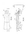
- FIG. 2Ais a top view of a probing member of a confocal surface topography measurement apparatus, in accordance with an embodiment
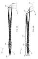
- FIG. 2Bis a longitudinal cross-section through the probing member of FIG. 2A , depicting exemplary rays passing therethrough;
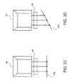
- FIGS. 2C and 2Dare end views of the probing member of FIG. 2A , in accordance with many embodiments;
- FIG. 3Aillustrates an optical probe scanning a structure using fixed focal positions, in accordance with many embodiments
- FIG. 3Bshows another view of the optical probe of FIG. 3A during scanning of the structure using fixed focal positions
- FIG. 4Aillustrates an optical assembly configured to focus a plurality of light beams to respective focal positions, in accordance with many embodiments
- FIG. 4Billustrates another optical assembly configured to focus a plurality of light beams to a diagonal focal plane, in accordance with many embodiments
- FIG. 5illustrates a micro lens array for focusing an array of light beams to a diagonal focal plane, in accordance with many embodiments
- FIG. 6Aillustrates another optical assembly configured to focus a plurality of light beams to a diagonal focal plane, in accordance with many embodiments
- FIG. 6Billustrates the optical path of returning light beams through the optical assembly of FIG. 6A , in accordance with many embodiments
- FIG. 7Aillustrates another optical assembly configured to focus a plurality of light beams to a diagonal focal plane, in accordance with many embodiments
- FIG. 7Billustrates an unfolded configuration of the optical assembly of FIG. 7A ;
- FIG. 8is a simplified block diagram depicting acts of a method for measuring surface topography using fixed focal positions, in accordance with many embodiments.
- incident light beams generated by a measurement apparatusare used to determine the surface topography of a three-dimensional structure.
- the apparatusincludes an optical probe from which the light beams emanate in order to illuminate the structure.
- the light beamsare focused by focusing optics to respective focal points (also known as focal positions) external to the optical probe.
- the focal positionsare optically scanned through a plurality of positions relative to the optical probe in order to measure the three-dimensional surface topography.
- the focal positionsare moved relative to the optical probe along a direction of propagation of the incident light beams (axial scanning).
- the focal positionscan also be moved orthogonal to the direction of propagation (transverse scanning) Any description herein relating to a direction of light can be regarded as referring to a direction of the principal rays (chief rays) of the light. Similarly, any description herein relating to a direction of propagation of light can be regarded as referring to a direction of propagation of the principal rays of the light.
- axial and/or transverse scanning relative to the optical probeis achieved by mechanically moving an optical element, for example via suitable devices, such as galvanometric mirrors, motors, and/or telescopic scanning mechanisms. The use of such axial or transverse scanning components, however, may increase the size, weight, and cost of the measurement apparatus.
- the apparatus and methods of the present disclosureperform confocal measurement of three-dimensional surface topography without optically moving the position of the focal positions relative to the optical probe.
- the approaches described hereinfocus each light beam to a respective focal point having a fixed spatial disposition relative to the optical probe. Relative movement between the optical probe and the three-dimensional structure is used to move the focal points relative to the structure. Distances between the optical probe and the three-dimensional structure are measured for a plurality of different positions and/or orientations between the optical probe and the three-dimensional structure. The data is then processed in conjunction with data regarding the relative position between the probe and the three-dimensional structure to determine surface topography of the measured structure.
- the apparatus and methods disclosed hereinmay be smaller, faster, and more cost-effective relative to existing optical measurement systems.
- the distance between the optical probe and the three-dimensional structureis determined by measuring one or more characteristics of returning light beams generated by illuminating the structure with the incident light beams.
- characteristicscan include, for example, intensity, wavelength, polarization, phase shift, interference, and/or dispersion of the returning light beams. Any description herein relating to light intensity can also be applied to other suitable characteristics of light, and vice-versa.
- the measurements of the characteristic(s)can be used to detect whether the incident light beams are focused on the surface of the structure and thereby determine the distance between the optical probe and the three-dimensional structure.
- the surface topography of the structurecan be determined based on measuring the intensities of the returning light beams.
- the apparatusis configured such that the intensity of any particular light beam returning from the structure is maximized when the incident light beam is focused on the surface of the structure.
- a distance between the probe and the structure for a particular light beam and position and orientation of the probe relative to the structurecan be determined by identifying when the intensity of the respective returning reflected light beam is maximized.
- the surface topography of the structurecan then be determined based on the measured intensities of the returned light beams and the position and/or orientation of the optical probe relative to the structure.
- the surface topographycan be determined by using spatial frequency analysis to identify which regions of the structure are in focus.
- focused regionswill contain higher spatial frequencies than out of focus regions. Accordingly, a distance between the probe and a specified region on the structure for a particular position and orientation of the probe relative to the structure can be determined by identifying when the spatial frequencies of the region are maximized. This approach can be applied to determine the surface topography of structures having spatial details.
- the apparatus and methods described hereincan be used to measure the surface topography of any suitable three-dimensional structure.
- optical measurementsare taken to generate data representing the three-dimensional surface topography of a patient's dentition.
- the datacan be used, for example, to produce a three-dimensional virtual model of the dentition that can be displayed and manipulated.
- the three-dimensional virtual modelscan be used to, for example, define spatial relationships of a patient's dentition that are used to create a dental prosthesis (e.g., a crown or a bridge) for the patient, provide a digital model or a physical model for record keeping purposes, set up a treatment plan, fabricate orthodontic appliances, or any other dental purpose.
- the surface topography datacan be stored and/or transmitted or output, such as to a manufacturing device that can be used to, for example, make a physical model of the patient's dentition that is used by a dental technician to create a dental prosthesis for the patient.
- an apparatusfor measuring surface topography of a three-dimensional structure.
- the apparatuscan be configured to: (a) focus each of a plurality of light beams to a respective fixed focal position relative to the apparatus; (b) measure a characteristic of each of a plurality of returned light beams that are generated by illuminating the three-dimensional structure with the light beams, the characteristic being measured for a plurality of different positions and/or orientations between the apparatus and the three-dimensional structure; and (c) determine surface topography of the three-dimensional structure based at least in part on the measured characteristic of the returned light beams for the plurality of the different positions and/or orientations between the apparatus and the three-dimensional structure.
- an apparatusfor measuring surface topography of a three-dimensional structure.
- the apparatusincludes an optical probe configured to be moved relative to the three-dimensional structure.
- the apparatusincludes an illumination unit configured to generate a plurality of incident light beams, each of the incident light beams comprising a first wavelength component.
- the apparatusincludes an optical system configured to focus the first wavelength component of each of the plurality of incident light beams to a respective fixed focal position relative to the optical probe.
- the apparatusincludes a detector unit configured to measure a characteristic of each of a plurality of returned light beams that are generated by illuminating the three-dimensional structure with the incident light beams.
- the apparatusincludes a processing unit coupled with the detector unit and configured to determine surface topography of the three-dimensional structure based at least in part on the measured characteristic of the plurality of returned light beams for a plurality of different relative positions and/or orientations between the optical probe and the three-dimensional structure.
- the characteristicis intensity.
- the detector unitincludes a two-dimensional array of sensor elements.
- Each sensor elementcan be configured to measure the characteristic for a corresponding returned light beam of the plurality of returned light beams.
- the optical systemcan be configured to form a two-dimensional pattern of the incident light beams from light generated by the illumination unit, the two-dimensional pattern of incident light beams corresponding to the returned light beams measured by the two-dimensional array of sensor elements.
- the optical systemcan include an optics expander unit configured to expand light generated by the illumination unit to form the two-dimensional pattern of the incident light beams.
- the illumination unitcan be configured to produce a two-dimensional pattern of the incident light beams corresponding to the returned light beams measured by the two-dimensional array of sensor elements.
- the incident light beamscan be focused to a plurality of respective focal lengths relative to the optical probe.
- the incident light beamscan be arranged in a plurality of rows having a first row and a last row.
- the incident light beams in each rowcan be focused to a respective common focal length.
- the focal lengths of the first row and the last rowcan be different by a predetermined length.
- the predetermined lengthcan be from 5 mm to 25 mm.
- the sensor elementscan be arranged in a plane that is oriented for confocal sensing of the returned light beams relative to focal lengths of the first wavelength component of the incident light beams. In some embodiments, the plane of the sensor elements is non-orthogonal to the returned light beams.
- the optical probeis moved through a plurality of different positions and/or orientations relative to the structure.
- the three-dimensional surface topographycan thus be reconstructed from the measured characteristic based at least in part on the position and/or orientation of the optical probe relative to the three-dimensional structure.
- Any suitable methodcan be used to determine the relative position and/or orientation between the optical probe and the structure.
- the processing unitincludes one or more processors and a tangible non-transitory storage device.
- the tangible non-transitory storage devicecan store instructions executable by the one or more processors to cause the one or more processors to process data of the measured characteristic generated using the detector unit for the plurality of different relative positions and/or orientations between the optical probe and the three-dimensional structure.
- the datacan be processed by the one or more processors to determine relative position and/or orientation between the optical probe and the three-dimensional structure.
- the apparatusfurther includes a motion tracking device configured to collect motion data.
- the processing unitcan include one or more processors and a tangible non-transitory storage device.
- the tangible non-transitory storage devicecan store instructions executable by the one or more processors to cause the one or more processors to process the motion data to determine relative position and/or orientation between the optical probe and the three-dimensional structure.
- the motion tracking devicecan include a camera and the motion data can include image data.
- the motion tracking devicecan include a gyroscope and/or an accelerometer.
- the motion tracking devicecan include an electromagnetic sensor.
- the optical systemcan be configured to focus the first wavelength component of the light beams to at least 10 different focal lengths relative to the scanner, and the focal lengths can have a range of at least 10 mm.
- a methodfor measuring surface topography of a three-dimensional structure.
- the methodcan include generating a plurality of incident light beams, each of the incident light beams including a first wavelength component.
- the first wavelength component of each of the incident light beamscan be focused to a respective focal position relative to an optical probe.
- a characteristic of each of a plurality of returned light beams that are generated by illuminating the three-dimensional structure with the incident light beamscan be measured for a plurality of different relative positions and/or orientations between the optical probe and the three-dimensional structure.
- the measured characteristic for the plurality of different relative positions and/or orientations between the optical probe and the three-dimensional structurecan be processed to generate surface topography data for the three-dimensional structure.
- the surface topography for the three-dimensional structurecan be generated using the surface topography data.
- the measured characteristicis intensity.
- the methodincludes tracking changes in relative position and/or orientation between the optical probe and the three-dimensional structure.
- the incident light beamscan be arranged in a plurality of rows having a first row and a last row.
- the incident light beams in each rowcan be focused to a respective common focal length.
- the focal lengths of the first row and the last rowcan be different by a predetermined length.
- the predetermined lengthcan be at least 10 mm.
- the incident light beamscan be focused to any suitable respective fixed positions relative to the probe.
- the wavelength component of the light beamscan be focused to at least 10 different focal lengths relative to the scanner, and the focal lengths can have a range of at least 10 mm.
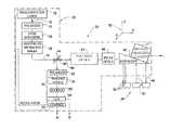
- FIGS. 1A and 1Billustrate an apparatus 20 for measuring surface topography optically.
- the apparatus 20includes an optical device 22 coupled to a processor 24 .
- the illustrated embodimentis particularly useful for measuring surface topography of a patient's teeth 26 .
- the apparatus 20can be used to measure surface topography of a portion of the patient's teeth where at least one tooth or portion of tooth is missing to generate surface topography data for subsequent use in design and/or manufacture of prosthesis for the patient (e.g., a crown or a bridge).
- the inventionis not limited to measuring surface topography of teeth, and applies, mutatis mutandis, also to a variety of other applications of imaging of three-dimensional structure of objects (e.g., for the recordal of archeological objects, for imaging of a three-dimensional structure of any suitable item such as a biological tissue, etc.).
- the optical device 22includes, in the illustrated embodiment, a light source (e.g., semiconductor laser unit 28 ) emitting a light, as represented by arrow 30 .
- the light beam 30can include a single wavelength component or multiple wavelength components. In some instances, light with multiple wavelength components can be generated by a plurality of light sources.
- the lightpasses through a polarizer 32 , which causes the light passing through the polarizer 32 to have a certain polarization.
- the lightthen enters into an optic expander 34 , which increases the diameter of the light beam 30 .
- the light beam 30then passes through a module 38 , which can, for example, be a grating or a micro lens array that splits the parent beam 30 into a plurality of light beams 36 , represented here, for ease of illustration, by a single line.
- a module 38can, for example, be a grating or a micro lens array that splits the parent beam 30 into a plurality of light beams 36 , represented here, for ease of illustration, by a single line.
- the optical device 22further includes a partially transparent mirror 40 having a small central aperture.
- the mirror 40allows transfer of light from the laser unit 28 through the downstream optics, but reflects light travelling in the opposite direction.
- other optical componentse.g., a beam splitter.
- the aperture in the mirror 40improves the measurement accuracy of the apparatus.
- the light beamsproduce a light annulus on the illuminated area of the imaged object as long as the area is not in focus.
- the annulusbecomes a sharply-focused illuminated spot when the light beam is in focus relative to the imaged object. Accordingly, a difference between the measured intensity when out-of-focus and in-focus is larger.
- Another advantage of a mirror of this kind, as opposed to a beam splitteris that internal reflections that occur in a beam splitter are avoided, and hence the signal-to-noise ratio is greater.
- the optical device 22further includes focusing optics 42 , relay optics 44 and an endoscopic probe member 46 .
- the focusing optics 42can include suitable optics for focusing the light beams 36 to a plurality of respective focal points at fixed spatial dispositions relative to the probe member 46 , as described below.
- the focusing optics 42is static, such that the optical device 22 does not employ mechanisms to scan the focal points (e.g., axially or transversely) relative to the probe member 46 .
- the relay optics 44is configured to maintain a certain numerical aperture of the light beam's propagation.
- the endoscopic probe member 46can include a light-transmitting medium, which can be a hollow object defining within it a light transmission path or an object made of a light-transmitting material (e.g., a glass body or tube).
- the light-transmitting mediummay be rigid or flexible (e.g., fiber optics).
- the endoscopic probe member 46includes a mirror of the kind ensuring total internal reflection and directing the incident light beams towards the patient's teeth 26 . The endoscope 46 thus emits a plurality of incident light beams 48 impinging on to the surface of the patient's teeth 26 .
- the endoscope 46can include one or more motion tracking elements 47 (e.g., a gyroscope, an accelerometer, targets for optical tracking, an electromagnetic sensor).
- the motion tracking element 47generates a motion tracking signal in response to movement of the endoscope 46 .
- the motion tracking signalis processed by the processor 24 to track changes in spatial disposition of the endoscope 46 in six degrees of freedom (i.e., three translational degrees of freedom and three rotational degrees of freedom).
- the incident light beams 48form a two-dimensional array of light beams arranged in a plane, relative to a Cartesian reference frame 50 , and propagating along the Z-axis.
- the light beams 48can be focused to respective focal points defining a suitable focal plane, such as a plane orthogonal to the Z axis (e.g., an X-Y plane) or a non-orthogonal plane.
- a suitable focal planesuch as a plane orthogonal to the Z axis (e.g., an X-Y plane) or a non-orthogonal plane.
- an illuminated spot 52 at one locationmay be in focus for a given relative spatial disposition between the endoscope 46 and the teeth 26
- illuminated spots 52 at other locationsmay be out-of-focus. Therefore, the light intensity of the returned light beams of the focused spots will be at its peak, while the light intensity at other spots will be off peak.
- light intensityis measured for different relative spatial dispositions between the endoscope 46 and the teeth 26 .
- the derivative of the intensity over timewill be made, and the relative spatial disposition(s) between the endoscope 46 and the teeth 26 wherein the derivative equals zero can be used to generate data that is used in conjunction with the relative spatial dispositions between the endoscope 26 and the teeth 26 to determine surface topography of the teeth.
- the incident lightforms a light disk on the surface when out of focus and a sharply-focused light spot only when in focus. Consequently, the distance derivative will exhibit a larger change in magnitude when approaching an in-focus position, thus increasing accuracy of the measurement.
- the light reflected from each of the illuminated spots 52includes a beam travelling initially in the Z-axis in the opposite direction of the optical path traveled by the incident light beams.
- Each returned light beam 54corresponds to one of the incident light beams 36 .
- the returned light beams 54are reflected in the direction of a detection assembly 60 .
- the detection assembly 60includes a polarizer 62 that has a plane of preferred polarization oriented normal to the polarization plane of polarizer 32 .
- the returned polarized light beam 54pass through imaging optics 64 , typically a lens or a plurality of lenses, and then through an array of pinholes 66 .
- a sensor array 68which can be a charge-coupled device (CCD) or any other suitable image sensor, includes a matrix of sensing elements.
- each sensing elementrepresents a pixel of the image and each sensing element corresponds to one pinhole in the array 66 .
- the sensor array 68is connected to an image-capturing module 80 of the processor unit 24 .
- the light intensity measured by each of the sensing elements of the sensor array 68is analyzed, in a manner described below, by the processor 24 .
- the optical device 22is depicted in FIGS. 1A and 1B as measuring light intensity, the device 22 can also be configured to measure other suitable characteristics (e.g., wavelength, polarization, phase shift, interference, dispersion), as previously described herein.
- the plane of the sensor array 68is orthogonal to the returned light beams 54 (e.g., orthogonal to a direction of propagation of the returned light beams).
- the plane of the sensor array 68is non-orthogonal to the returned light beams 54 , as described below.
- the optical device 22includes a control module 70 that controls operation of the semi-conducting laser 28 .
- the control module 70synchronizes the operation of the image-capturing module 80 with the operation of the laser 28 during acquisition of data representative of the light intensity (or other characteristic) from each of the sensing elements.
- the intensity data and data of relative spatial dispositions between the endoscope 46 and the teeth 26are processed by the processor 24 per processing software 82 to obtain data representative of the three-dimensional topography of the external surfaces of the teeth 26 . Exemplary embodiments of methods for processing the data of the characteristic and relative spatial disposition data are described below.
- a resulting three-dimensional representation of the measured structurecan be displayed on a display 84 and manipulated for viewing (e.g., viewing from different angles, zooming-in or out) by a user control module 85 (typically a computer keyboard).
- a user control module 85typically a computer keyboard
- the data representative of the surface topographycan be transmitted through an appropriate data port such as, for example, a modem 88 or any suitable communication network (e.g., a telephone network, the Internet) to a recipient (e.g., to an off-site CAD/CAM apparatus).
- an accurate three-dimensional representation of the structurecan be generated.
- the three-dimensional data and/or the resulting three-dimensional representationcan be used to create a virtual model of the three-dimensional structure in a computerized environment and/or a physical model fabricated in any suitable fashion (e.g., via a computer controlled milling machine, a rapid prototyping apparatus such as a stereolithography apparatus or 3 D printing apparatus).
- a probing member 90is illustrated in accordance with many embodiments.
- the probing member 90forms at least a portion of the endoscope 46 .
- the probing member 90can be made of a light transmissive material (e.g., glass, crystal, plastic, etc.) and includes a distal segment 91 and a proximal segment 92 , tightly glued together in an optically transmissive manner at 93 .
- a slanted face 94is covered by a reflective mirror layer 95 .
- a transparent disk 96(e.g., made of glass, crystal, plastic, or any other suitable transparent material) defining a sensing surface 97 is disposed along the optical path distal to the mirror layer 95 so as to leave an air gap 98 between the transparent disk 96 and the distal segment 91 .
- the transparent disk 96is fixed in position by a holding structure (not shown).
- Three light rays 99are represented schematically. As can be seen, the light rays 99 reflect from the walls of the probing member 90 at an angle in which the walls are totally reflective, reflect from the mirror layer 95 , and then propagate through the sensing face 97 .
- the light rays 99can be focused external to the probing member 90 with any suitable combination of respective focal lengths, in many embodiments, the light rays 99 are focused on a focusing plane 100 external to the probing member 90 .
- the light rays 99are focused to a common focal length, thereby being focused on a focusing plane 100 that is perpendicular to the direction of propagation of the light rays 99 external to the probing member 90 (also referred to herein as the Z-axis).
- the Z-axisalso referred to herein as the Z-axis.
- the light rays 99are focused to different focal lengths so as to be focused on a focusing plane 100 that is non-perpendicular to the Z-axis. While two configurations of focal positions are illustrated and described, any suitable configuration of focal positions can be employed.
- FIGS. 3A and 3Billustrate an optical probe 200 scanning a structure 202 in a global Cartesian reference frame 204 , in accordance with many embodiments.
- FIG. 3Bshows the cross-sectional view I-I as defined in FIG. 3A ).
- the optical probe 200can be used with any suitable scanning device or system described herein, such as the optical device 22 .
- a two-dimensional array of incident light beams 206 emanating from the optical probe 200are arranged in a plurality of rows extending in the X direction, including a first row 208 and a last row 210 . Each row of the array of light beams 206 is focused to a respective common focal length along the Z direction, thereby forming a diagonal focal plane 212 .
- the focal lengths of the first row 208 and the last row 210differ by a predetermined length 214 in the Z direction.
- the optical probe 200can be moved relative to the structure 202 to scan the structure 202 with the light beams 206 .
- the optical probe 200can be translated in the Y direction from a first position 216 to a second position 218 .
- each row in the array of light beams 206is focused to a different depth along the Z direction so as to produce a focal plane 212 that is not orthogonal to the Z-axis. Therefore, as the optical probe 200 is moved relative to the structure 202 , the focal plane 212 of the light beams 206 sweeps through a three-dimensional volume of the structure 202 . For example, as the optical probe 200 translates from position 216 to position 218 , the focal plane 212 sweeps a three-dimensional volume having a Z depth 214 . Accordingly, the optical probe 200 can scan the structure 202 in the Z direction through continuous movement of the optical probe 200 relative to structure 202 , while maintaining constant respective focal lengths of the light beams 206 .
- the optical probe 200can be moved with six degrees of freedom (e.g., three degrees of freedom in translation and three degrees of freedom in rotation) to a plurality of different relative positions and/or orientations between the optical probe 200 and the structure 202 .
- six degrees of freedome.g., three degrees of freedom in translation and three degrees of freedom in rotation
- the array of light beams 206can be provided in any suitable configuration.
- the array of light beams 206can be focused to any suitable number of different focal lengths relative to the optical probe 200 , such as 3, 5, 10, 50, or 100 or more different focal lengths.
- the focal lengths of the array of light beams 206can be configured to have any suitable range, such as at least 5 mm, 7.5 mm, or 10 mm or more.
- the focal lengths of the first row 208 and the last row 210 in the array of light beams 206can be different by any suitable length, such as by 5 mm or less, 10 mm, 15 mm, or 25 mm or greater.
- the focal lengthscan be different by a length within the range of 5 mm to 25 mm.
- the array of light beams 206can be generated by any system or device suitable for focusing a wavelength component of each of the light beams to a respective focal position (e.g., a diagonal focal plane 212 ).
- one or more optics of the optical device 22can be used to focus an array of light beams to a plurality of fixed focal positions relative to the probe.
- suitable embodiments of the optics described hereincan be included within the grating or micro lens array 38 , focusing optics 42 , relay optics 44 , optics within the endoscope 46 , or suitable combinations thereof.
- the opticscan be configured to be used with telecentric and/or non-telecentric confocal focusing optics.
- FIG. 4Aillustrates an optical assembly 300 for focusing a plurality of light beams to respective focal positions, in accordance with many embodiments.
- an array of light beams 302emanate from a source array 304 (e.g., a micro lens array), are focused by focusing optics 306 , and reflect off a mirror 308 (e.g., a mirror disposed within an endoscopic probing member) to form a focal plane 310 .
- the mirror 308can be positioned at a 45° angle relative to the optical axis in order to produce an orthogonal focal plane 310 .
- FIG. 4Billustrates an optical assembly 320 for focusing a plurality of light beams to a diagonal focal plane, in accordance with many embodiments.
- the system 320includes a source array 324 that produces an array of light beams 322 , focusing optics 326 , and a mirror 328 .
- the mirror 328is tilted at a suitable angle relative to the optical axis, such as a 30° angle, in order to produce a focal plane 330 that is inclined relative to the scanner 332 .
- the focal plane 330can be used to scan a three-dimensional structure, such as a tooth 334 , using fixed focal positions as described herein.
- FIG. 5illustrates a micro lens array 400 for focusing an array of light beams to a diagonal focal plane, in accordance with many embodiments.
- the micro lensese.g., micro lens elements 402
- the micro lensesare arranged in a plurality of rows 404 , including a first row 406 and a last row 408 .
- Each row of micro lensesis configured to focus light beams to a different focal length, thereby producing a diagonal focal plane.
- FIG. 6Aillustrates an optical assembly 500 for focusing a plurality of light beams to a diagonal focal plane, in accordance with many embodiments.
- the optical assembly 500includes a tilted source array 502 , which can be a micro lens array tilted at a suitable angle relative to the optical axis.
- the array of light beams 504 produced by the tilted source array 502passes through focusing optics 506 , and reflects off mirror 508 to form a diagonal focal plane 510 , suitable for scanning the structure 512 with fixed focal positions as described herein.
- FIG. 6Billustrates the optical path of returned light beams 514 through the optical assembly 500 .
- the returned light beams 514 reflected from the structure 512pass back through the focusing optics 506 , and are directed by beam splitter 516 onto the sensor array 518 .
- the sensor array 518can include a plurality of sensor elements arranged in a plane.
- the sensor array 518is non-orthogonal relative to the returned light beams 514 , such that the plane of sensor elements is tilted relative to the direction of propagation of the returned light beams 514 .
- the planecan be tilted by the same amount as the source array 502 in order to allow for confocal sensing of the returned light beams 502 .
- FIG. 7Aillustrates an optical assembly 600 for focusing a plurality of light beams to a diagonal focal plane, in accordance with many embodiments.
- FIG. 7Billustrates an unfolded configuration of the optical assembly 600 .
- an array of light beams 604 emanating from a source array 602pass through focusing optics 606 .
- a non-symmetric optics 608is disposed between the focusing optics 606 and a mirror 610 and configured to focus the light beams to a diagonal focal plane 612 suitable for scanning the structure 614 with fixed focal positions as described herein. Any suitable optical element or combination of optical elements can be used for the non-symmetric optics 608 .
- the non-symmetric optics 608can include an off-axis lens tilted at a suitable angle relative to the optical axis.
- the non-symmetric optics 608can include a Fresnel lens including a plurality of segments configured to refract each of the plurality of light beams to a respective focal position in order to produce a suitable diagonal focal plane.
- the global surface topography of the structurecan be reconstructed by spatially aligning the local intensity data to each other.
- the relative position and/or orientation between the optical probe and the structure during the scanning procedureis used to determine the spatial relationships between the intensity data and thereby align the data.
- Any suitable method or combination of methodscan be used to track the position and/or orientation of the optical probe or a suitable portion of the optical probe (e.g., the scanning tip of the endoscope 46 or probing member 90 ) relative to the structure, such as a suitable motion estimation or motion tracking method.
- one or more motion tracking devicescan be used to generate motion data suitable for determining the position and/or orientation of the optical probe relative to the three-dimensional structure.
- an optical tracking methodis used to determine the spatial disposition of the probe relative to the structure with respect to six degrees of freedom.
- the motion tracking devicecan include an external camera (or any other suitable image sensor) to generate image data of the probe as it is moved between a plurality of different positions and/or orientations during the scanning procedure.
- the cameracan capture images of any suitable portion of the probe, such as a portion positioned outside of the patient's intraoral cavity.
- the cameracan capture images of one or more suitable markers (e.g., included in motion tracking element 47 ) placed on one or more suitable portions of the probe.
- the imagescan be processed to estimate the position and/or orientation of the probe relative to the structure using any suitable machine vision method (e.g., a structure from motion algorithm, a photogrammetric method, an image registration/alignment method, and/or an optical flow estimation method such as a Lucas-Kanade method).
- a cameracan be integrated into or coupled with the probe, such that image data captured by the camera can be analyzed using a suitable ego-motion estimation method, such as the machine vision methods described herein, to determine the position and/or orientation of the probe relative to the structure.
- the motion tracking devicecan utilize inertial-based estimation methods to determine the relative position and/or orientation of the probe.
- the motion sensorcan include an inertial measurement unit, such as an inertial sensor.
- the inertial sensorcan be a micro electromechanical system (MEMS) device.
- MEMSmicro electromechanical system
- the inertial sensorincludes a plurality of accelerometers and/or a plurality of gyroscopes configured to detect motion of the probe with respect to three degrees of translation and/or three degrees of rotation.
- an electromagnetic tracking (EMT) systemcan be used to track the position and/or orientation of the probe relative to the structure.
- EMTelectromagnetic tracking
- an EMT fieldcan be provided by a suitable generator or transmitter, and the position and/or orientation of an EMT sensor within the field (e.g., with respect to up to three degrees of freedom in rotation and three degrees of freedom in translation) can be determined based on the electromagnetic signals detected by the sensor. Any suitable number and configuration of EMT field generators and EMT sensors can be used.
- an EMT field generatorcan be situated at a fixed location at the site of the scanning procedure (e.g., coupled to an operating table or patient chair) and an EMT sensor can be disposed on the probe (e.g., included in motion tracking element 47 ) to track the motion of the probe.
- EMT sensorsare also be placed on or near the three-dimensional structure (e.g., on a patient's head, face, jaw, and/or teeth) in order to account for any motion of the structure during the measurement procedure.
- the EMT field generatorcan be placed on the structure and used to track the relative motion of a probe having a coupled EMT sensor.
- the EMT field generatorcan be located on the probe and the EMT sensor can be located on the structure.
- any suitable methodcan be used to process the motion data to determine the position and/or orientation of the probe relative to the structure.
- the datacan be processed using a motion tracking algorithm combined with a Kalman filter.
- the processingcan utilize motion data received from a plurality of the different types of motion tracking systems and devices described herein.
- FIG. 8is a simplified block diagram depicting acts of a method 700 for measuring surface topography of a three-dimensional structure, in accordance with many embodiments. Any suitable optical devices or systems, such as the embodiments described herein, can be used to practice the method 700 .
- a plurality of incident light beamsis generated.
- the optical device 22can be used to form a two-dimensional pattern of light beams as described herein.
- each of the plurality of incident light beamsis focused to a respective focal position relative to an optical probe.
- Any suitable focusing mechanismcan be used, such as the embodiments described herein.
- the light beamsare focused to form a diagonal focal plane to provide Z scanning with motion of the probe, as previously described herein.
- a three-dimensional structureis illuminated with the incident light beams for a plurality of relative positions and/or orientations between the probe and the structure.
- the light beamsare focused to a diagonal focal plane such that movement of the probe through a plurality of positions and/or orientations relative to the structure enables three-dimensional scanning of the structure, as described herein.
- a plurality of returning light beamsare produced by illuminating the structure with the incident light beams, with each returning light beam corresponding to an incident light beam.
- a characteristic of each of a plurality of light beams returning from the three-dimensional structureis measured.
- the characteristiccan be any suitable measurable parameter of the light beams, such as intensity, wavelength, polarization, phase shift, interference, or dispersion.
- Any suitable device configured to measure the characteristic of each of the light beamscan be used.
- a suitable detector unitsuch as a sensor (e.g., sensory array 68 ) including a two-dimensional array of sensor elements can be used, as previously described herein.
- the sensor arraycan be orthogonal or non-orthogonal to the returning light beams, based on the configuration of the focusing optics and the light source array.
- the measured characteristic and the corresponding relative positions and/or orientations between the optical probe and the structureare processed (e.g., by processor 24 ) to generate surface topography data for the structure.
- Any suitable method for processing the data of the measured characteristiccan be used, such as the embodiments described herein.
- the data of the measured characteristicis aligned based on data obtained by tracking the relative position and/or orientation of the optical probe (e.g., motion data and/or image data) as described herein.
- act 760surface topography for the three-dimensional structure is generated, such as by the processor 24 as described herein.
- the resultant three-dimensional representation of the structurecan be used for any suitable application, such as the dental and orthodontic procedures described herein.
Landscapes
- Physics & Mathematics (AREA)
- General Physics & Mathematics (AREA)
- Health & Medical Sciences (AREA)
- Optics & Photonics (AREA)
- Engineering & Computer Science (AREA)
- Computer Vision & Pattern Recognition (AREA)
- General Health & Medical Sciences (AREA)
- Life Sciences & Earth Sciences (AREA)
- Oral & Maxillofacial Surgery (AREA)
- Public Health (AREA)
- Veterinary Medicine (AREA)
- Animal Behavior & Ethology (AREA)
- Epidemiology (AREA)
- Dentistry (AREA)
- Astronomy & Astrophysics (AREA)
- Radiology & Medical Imaging (AREA)
- Chemical & Material Sciences (AREA)
- Analytical Chemistry (AREA)
- Surgery (AREA)
- Ophthalmology & Optometry (AREA)
- Electromagnetism (AREA)
- Computer Networks & Wireless Communication (AREA)
- Radar, Positioning & Navigation (AREA)
- Remote Sensing (AREA)
- Biophysics (AREA)
- Biomedical Technology (AREA)
- Length Measuring Devices By Optical Means (AREA)
- Endoscopes (AREA)
- Dental Tools And Instruments Or Auxiliary Dental Instruments (AREA)
Abstract
Description
This application is a continuation application of U.S. patent application Ser. No. 14/980,580, filed Dec. 28, 2015, now U.S. Pat. No. 9,675,429, which is a continuation application of U.S. patent application Ser. No. 14/323,237, filed Jul. 3, 2014, now U.S. Pat. No. 9,261,356, each of which are incorporated herein by reference in their entirety.
A variety of approaches have been developed for measuring surface topography optically. For example, optical systems and methods have been developed and employed that can be used to optically measure surface topography of a patient's teeth. The measured surface topography of the teeth can be used, for example, to design and manufacture a dental prosthesis and/or to determine an orthodontic treatment plan to correct a malocclusion.
One technique for measuring surface topography optically employs laser triangulation to measure distance between a surface of the tooth and an optical distance probe, which is inserted into the oral cavity of the patient. Surface topography measured via laser triangulation, however, may be less accurate than desired due to, for example, sub-optimal reflectivity from the surface of the tooth.
Other techniques for measuring surface topography optically, which are embodied in CEREC-1 and CEREC-2 systems commercially available from Siemens GmbH or Sirona Dental Systems, utilize the light-section method and phase-shift method, respectively. Both systems employ a specially designed hand-held probe to measure the three-dimensional coordinates of a prepared tooth. Both of these approaches, however, require a specific coating (i.e. measurement powder and white-pigments suspension, respectively) to be deposited on the tooth. The thickness of the coating layer should meet specific, difficult to control requirements, which can lead to inaccuracies in the measurement data.
In yet another technique, mapping of teeth surface topography is based on physical scanning of the surface by a probe and by determining the probe's position, e.g., by optical or other remote sensing means.
U.S. Pat. No. 5,372,502 discloses an optical probe for three-dimensional surveying. Various patterns are projected onto the tooth or teeth to be measured and a corresponding plurality of distorted patterns are captured by the optical probe. Each captured pattern can be used to refine the topography measurement.
Apparatus and methods for measuring surface topography of a three-dimensional structure are provided. In many embodiments, an apparatus for measuring surface topography is configured to illuminate the three-dimensional structure (e.g., a patient's dentition) with light beams for a plurality of different positions and/or orientations between an optical probe of the apparatus and the three-dimensional structure. The apparatus and methods disclosed employ confocal scanning of the three-dimensional structure without optically moving the focal positions of the light beams relative to the optical probe, but instead use movement of the optical probe relative to the structure, thus enabling smaller, faster, and more cost-effective optics.
Thus, in one aspect, an apparatus is described for measuring surface topography of a three-dimensional structure. The apparatus is configured to measure a characteristic of each of a plurality of returned light beams that are generated by illuminating the three-dimensional structure with a plurality of light beams. The characteristic is measured for a plurality of different positions and/or orientations between the apparatus and the three-dimensional structure.
In another aspect, an apparatus is described for measuring surface topography of a three-dimensional structure. In many embodiments, the apparatus includes an optical probe, an optical system, and a processing unit. The optical probe is moved relative to the three-dimensional structure. The optical system focuses each of a plurality of incident light beams to a respective focal position relative to and distal to the optical probe. Returned light beams are generated by illuminating the three-dimensional structure with the incident light beams. The processing unit determines surface topography of the three-dimensional structure based at least in part on a measured characteristic of the returned light beams for a plurality of different relative positions and/or orientations between the optical probe and the three-dimensional structure.
In another aspect, a method is described for measuring surface topology of a three-dimensional structure. The method includes focusing each of a plurality of incident light beams to a respective focal point relative to and distal to an optical probe. Returned light beams are generated by illuminating the three-dimensional structure with the incident light beams. A characteristic of the returned light beams is measured for a plurality of different relative positions and/or orientations between the optical probe and the three-dimensional structure to generate surface topography data for the three-dimensional structure.
Other objects and features of the present invention will become apparent by a review of the specification, claims, and appended figures.
The novel features of the invention are set forth with particularity in the appended claims. A better understanding of the features and advantages of the present invention will be obtained by reference to the following detailed description that sets forth illustrative embodiments, in which the principles of the invention are utilized, and the accompanying drawings of which:
Apparatus and methods are described herein that employ confocal measurement of surface topography. In some approaches, such as those described in U.S. Pat. No. 6,697,164, the disclosure of which is herein incorporated by reference in its entirety, incident light beams generated by a measurement apparatus are used to determine the surface topography of a three-dimensional structure. The apparatus includes an optical probe from which the light beams emanate in order to illuminate the structure. The light beams are focused by focusing optics to respective focal points (also known as focal positions) external to the optical probe. The focal positions are optically scanned through a plurality of positions relative to the optical probe in order to measure the three-dimensional surface topography. The focal positions are moved relative to the optical probe along a direction of propagation of the incident light beams (axial scanning). The focal positions can also be moved orthogonal to the direction of propagation (transverse scanning) Any description herein relating to a direction of light can be regarded as referring to a direction of the principal rays (chief rays) of the light. Similarly, any description herein relating to a direction of propagation of light can be regarded as referring to a direction of propagation of the principal rays of the light. Typically, axial and/or transverse scanning relative to the optical probe is achieved by mechanically moving an optical element, for example via suitable devices, such as galvanometric mirrors, motors, and/or telescopic scanning mechanisms. The use of such axial or transverse scanning components, however, may increase the size, weight, and cost of the measurement apparatus.
In contrast, the apparatus and methods of the present disclosure perform confocal measurement of three-dimensional surface topography without optically moving the position of the focal positions relative to the optical probe. In contrast to the above-described approaches that optically scan the focal positions relative to the optical probe, the approaches described herein focus each light beam to a respective focal point having a fixed spatial disposition relative to the optical probe. Relative movement between the optical probe and the three-dimensional structure is used to move the focal points relative to the structure. Distances between the optical probe and the three-dimensional structure are measured for a plurality of different positions and/or orientations between the optical probe and the three-dimensional structure. The data is then processed in conjunction with data regarding the relative position between the probe and the three-dimensional structure to determine surface topography of the measured structure. By avoiding the use of optical scanning mechanisms, the apparatus and methods disclosed herein may be smaller, faster, and more cost-effective relative to existing optical measurement systems.
In many embodiments, the distance between the optical probe and the three-dimensional structure is determined by measuring one or more characteristics of returning light beams generated by illuminating the structure with the incident light beams. Such characteristics can include, for example, intensity, wavelength, polarization, phase shift, interference, and/or dispersion of the returning light beams. Any description herein relating to light intensity can also be applied to other suitable characteristics of light, and vice-versa. The measurements of the characteristic(s) can be used to detect whether the incident light beams are focused on the surface of the structure and thereby determine the distance between the optical probe and the three-dimensional structure.
For example, the surface topography of the structure can be determined based on measuring the intensities of the returning light beams. In many embodiments, the apparatus is configured such that the intensity of any particular light beam returning from the structure is maximized when the incident light beam is focused on the surface of the structure. By moving the probe relative to the structure, a distance between the probe and the structure for a particular light beam and position and orientation of the probe relative to the structure can be determined by identifying when the intensity of the respective returning reflected light beam is maximized. The surface topography of the structure can then be determined based on the measured intensities of the returned light beams and the position and/or orientation of the optical probe relative to the structure.
As another example, the surface topography can be determined by using spatial frequency analysis to identify which regions of the structure are in focus. In many embodiments, focused regions will contain higher spatial frequencies than out of focus regions. Accordingly, a distance between the probe and a specified region on the structure for a particular position and orientation of the probe relative to the structure can be determined by identifying when the spatial frequencies of the region are maximized. This approach can be applied to determine the surface topography of structures having spatial details.
The apparatus and methods described herein can be used to measure the surface topography of any suitable three-dimensional structure. In many embodiments, optical measurements are taken to generate data representing the three-dimensional surface topography of a patient's dentition. The data can be used, for example, to produce a three-dimensional virtual model of the dentition that can be displayed and manipulated. The three-dimensional virtual models can be used to, for example, define spatial relationships of a patient's dentition that are used to create a dental prosthesis (e.g., a crown or a bridge) for the patient, provide a digital model or a physical model for record keeping purposes, set up a treatment plan, fabricate orthodontic appliances, or any other dental purpose. The surface topography data can be stored and/or transmitted or output, such as to a manufacturing device that can be used to, for example, make a physical model of the patient's dentition that is used by a dental technician to create a dental prosthesis for the patient.
In one aspect, an apparatus is provided for measuring surface topography of a three-dimensional structure. The apparatus can be configured to: (a) focus each of a plurality of light beams to a respective fixed focal position relative to the apparatus; (b) measure a characteristic of each of a plurality of returned light beams that are generated by illuminating the three-dimensional structure with the light beams, the characteristic being measured for a plurality of different positions and/or orientations between the apparatus and the three-dimensional structure; and (c) determine surface topography of the three-dimensional structure based at least in part on the measured characteristic of the returned light beams for the plurality of the different positions and/or orientations between the apparatus and the three-dimensional structure.
In another aspect, an apparatus is provided for measuring surface topography of a three-dimensional structure. The apparatus includes an optical probe configured to be moved relative to the three-dimensional structure. The apparatus includes an illumination unit configured to generate a plurality of incident light beams, each of the incident light beams comprising a first wavelength component. The apparatus includes an optical system configured to focus the first wavelength component of each of the plurality of incident light beams to a respective fixed focal position relative to the optical probe. The apparatus includes a detector unit configured to measure a characteristic of each of a plurality of returned light beams that are generated by illuminating the three-dimensional structure with the incident light beams. The apparatus includes a processing unit coupled with the detector unit and configured to determine surface topography of the three-dimensional structure based at least in part on the measured characteristic of the plurality of returned light beams for a plurality of different relative positions and/or orientations between the optical probe and the three-dimensional structure. In many embodiments, the characteristic is intensity.
In many embodiments, the detector unit includes a two-dimensional array of sensor elements. Each sensor element can be configured to measure the characteristic for a corresponding returned light beam of the plurality of returned light beams. The optical system can be configured to form a two-dimensional pattern of the incident light beams from light generated by the illumination unit, the two-dimensional pattern of incident light beams corresponding to the returned light beams measured by the two-dimensional array of sensor elements. The optical system can include an optics expander unit configured to expand light generated by the illumination unit to form the two-dimensional pattern of the incident light beams. The illumination unit can be configured to produce a two-dimensional pattern of the incident light beams corresponding to the returned light beams measured by the two-dimensional array of sensor elements.
The incident light beams can be focused to a plurality of respective focal lengths relative to the optical probe. In many embodiments, the incident light beams can be arranged in a plurality of rows having a first row and a last row. The incident light beams in each row can be focused to a respective common focal length. The focal lengths of the first row and the last row can be different by a predetermined length. For example, the predetermined length can be from 5 mm to 25 mm. The sensor elements can be arranged in a plane that is oriented for confocal sensing of the returned light beams relative to focal lengths of the first wavelength component of the incident light beams. In some embodiments, the plane of the sensor elements is non-orthogonal to the returned light beams.
In many embodiments, the optical probe is moved through a plurality of different positions and/or orientations relative to the structure. The three-dimensional surface topography can thus be reconstructed from the measured characteristic based at least in part on the position and/or orientation of the optical probe relative to the three-dimensional structure. Any suitable method can be used to determine the relative position and/or orientation between the optical probe and the structure. In many embodiments, the processing unit includes one or more processors and a tangible non-transitory storage device. The tangible non-transitory storage device can store instructions executable by the one or more processors to cause the one or more processors to process data of the measured characteristic generated using the detector unit for the plurality of different relative positions and/or orientations between the optical probe and the three-dimensional structure. The data can be processed by the one or more processors to determine relative position and/or orientation between the optical probe and the three-dimensional structure.
In many embodiments, the apparatus further includes a motion tracking device configured to collect motion data. The processing unit can include one or more processors and a tangible non-transitory storage device. The tangible non-transitory storage device can store instructions executable by the one or more processors to cause the one or more processors to process the motion data to determine relative position and/or orientation between the optical probe and the three-dimensional structure. For example, the motion tracking device can include a camera and the motion data can include image data. In another example, the motion tracking device can include a gyroscope and/or an accelerometer. As a further example, the motion tracking device can include an electromagnetic sensor.
Any suitable configuration of the plurality of incident light beams can be used. For example, the optical system can be configured to focus the first wavelength component of the light beams to at least 10 different focal lengths relative to the scanner, and the focal lengths can have a range of at least 10 mm.
In another aspect, a method is provided for measuring surface topography of a three-dimensional structure. The method can include generating a plurality of incident light beams, each of the incident light beams including a first wavelength component. The first wavelength component of each of the incident light beams can be focused to a respective focal position relative to an optical probe. A characteristic of each of a plurality of returned light beams that are generated by illuminating the three-dimensional structure with the incident light beams can be measured for a plurality of different relative positions and/or orientations between the optical probe and the three-dimensional structure. The measured characteristic for the plurality of different relative positions and/or orientations between the optical probe and the three-dimensional structure can be processed to generate surface topography data for the three-dimensional structure. The surface topography for the three-dimensional structure can be generated using the surface topography data. In many embodiments, the measured characteristic is intensity. In many embodiments, the method includes tracking changes in relative position and/or orientation between the optical probe and the three-dimensional structure.
The incident light beams can be arranged in a plurality of rows having a first row and a last row. For example, the incident light beams in each row can be focused to a respective common focal length. The focal lengths of the first row and the last row can be different by a predetermined length. For example, the predetermined length can be at least 10 mm. The incident light beams can be focused to any suitable respective fixed positions relative to the probe. For example, the wavelength component of the light beams can be focused to at least 10 different focal lengths relative to the scanner, and the focal lengths can have a range of at least 10 mm.
Turning now to the drawings, in which like numbers designate like elements in the various figures,FIGS. 1A and 1B illustrate anapparatus 20 for measuring surface topography optically. Theapparatus 20 includes anoptical device 22 coupled to aprocessor 24. The illustrated embodiment is particularly useful for measuring surface topography of a patient'steeth 26. For example, theapparatus 20 can be used to measure surface topography of a portion of the patient's teeth where at least one tooth or portion of tooth is missing to generate surface topography data for subsequent use in design and/or manufacture of prosthesis for the patient (e.g., a crown or a bridge). It should be noted, however, that the invention is not limited to measuring surface topography of teeth, and applies, mutatis mutandis, also to a variety of other applications of imaging of three-dimensional structure of objects (e.g., for the recordal of archeological objects, for imaging of a three-dimensional structure of any suitable item such as a biological tissue, etc.).
Theoptical device 22 includes, in the illustrated embodiment, a light source (e.g., semiconductor laser unit28) emitting a light, as represented byarrow 30. Thelight beam 30 can include a single wavelength component or multiple wavelength components. In some instances, light with multiple wavelength components can be generated by a plurality of light sources. The light passes through apolarizer 32, which causes the light passing through thepolarizer 32 to have a certain polarization. The light then enters into anoptic expander 34, which increases the diameter of thelight beam 30. Thelight beam 30 then passes through amodule 38, which can, for example, be a grating or a micro lens array that splits theparent beam 30 into a plurality oflight beams 36, represented here, for ease of illustration, by a single line.
Theoptical device 22 further includes a partiallytransparent mirror 40 having a small central aperture. Themirror 40 allows transfer of light from thelaser unit 28 through the downstream optics, but reflects light travelling in the opposite direction. It should be noted that in principle, rather than a partially transparent mirror, other optical components with a similar function may be used (e.g., a beam splitter). The aperture in themirror 40 improves the measurement accuracy of the apparatus. As a result of this mirror structure, the light beams produce a light annulus on the illuminated area of the imaged object as long as the area is not in focus. The annulus becomes a sharply-focused illuminated spot when the light beam is in focus relative to the imaged object. Accordingly, a difference between the measured intensity when out-of-focus and in-focus is larger. Another advantage of a mirror of this kind, as opposed to a beam splitter, is that internal reflections that occur in a beam splitter are avoided, and hence the signal-to-noise ratio is greater.
Theoptical device 22 further includes focusingoptics 42,relay optics 44 and anendoscopic probe member 46. The focusingoptics 42 can include suitable optics for focusing the light beams36 to a plurality of respective focal points at fixed spatial dispositions relative to theprobe member 46, as described below. In many embodiments, the focusingoptics 42 is static, such that theoptical device 22 does not employ mechanisms to scan the focal points (e.g., axially or transversely) relative to theprobe member 46. In many embodiments, therelay optics 44 is configured to maintain a certain numerical aperture of the light beam's propagation.
Theendoscopic probe member 46 can include a light-transmitting medium, which can be a hollow object defining within it a light transmission path or an object made of a light-transmitting material (e.g., a glass body or tube). The light-transmitting medium may be rigid or flexible (e.g., fiber optics). In many embodiments, theendoscopic probe member 46 includes a mirror of the kind ensuring total internal reflection and directing the incident light beams towards the patient'steeth 26. Theendoscope 46 thus emits a plurality of incident light beams48 impinging on to the surface of the patient'steeth 26.
Theendoscope 46 can include one or more motion tracking elements47 (e.g., a gyroscope, an accelerometer, targets for optical tracking, an electromagnetic sensor). In many embodiments, themotion tracking element 47 generates a motion tracking signal in response to movement of theendoscope 46. In many embodiments, the motion tracking signal is processed by theprocessor 24 to track changes in spatial disposition of theendoscope 46 in six degrees of freedom (i.e., three translational degrees of freedom and three rotational degrees of freedom).
In many embodiments, the incident light beams48 form a two-dimensional array of light beams arranged in a plane, relative to aCartesian reference frame 50, and propagating along the Z-axis. The light beams48 can be focused to respective focal points defining a suitable focal plane, such as a plane orthogonal to the Z axis (e.g., an X-Y plane) or a non-orthogonal plane. When the incident light beams48 are incident upon an uneven surface, the resulting array of illuminatedspots 52 are displaced from one another along the Z-axis, at different (Xi,Yi) locations. Thus, while an illuminatedspot 52 at one location may be in focus for a given relative spatial disposition between theendoscope 46 and theteeth 26, illuminatedspots 52 at other locations may be out-of-focus. Therefore, the light intensity of the returned light beams of the focused spots will be at its peak, while the light intensity at other spots will be off peak. Thus, for each illuminated spot, light intensity is measured for different relative spatial dispositions between theendoscope 46 and theteeth 26. Typically, the derivative of the intensity over time will be made, and the relative spatial disposition(s) between theendoscope 46 and theteeth 26 wherein the derivative equals zero can be used to generate data that is used in conjunction with the relative spatial dispositions between theendoscope 26 and theteeth 26 to determine surface topography of the teeth. As pointed out above, as a result of use of the mirror withaperture 40, the incident light forms a light disk on the surface when out of focus and a sharply-focused light spot only when in focus. Consequently, the distance derivative will exhibit a larger change in magnitude when approaching an in-focus position, thus increasing accuracy of the measurement.
The light reflected from each of the illuminatedspots 52 includes a beam travelling initially in the Z-axis in the opposite direction of the optical path traveled by the incident light beams. Each returnedlight beam 54 corresponds to one of the incident light beams36. Given the asymmetrical properties ofmirror 40, the returnedlight beams 54 are reflected in the direction of adetection assembly 60. Thedetection assembly 60 includes apolarizer 62 that has a plane of preferred polarization oriented normal to the polarization plane ofpolarizer 32. The returnedpolarized light beam 54 pass throughimaging optics 64, typically a lens or a plurality of lenses, and then through an array ofpinholes 66. Each returnedlight beam 54 passes at least partially through a respective pinhole of the array ofpinholes 66. Asensor array 68, which can be a charge-coupled device (CCD) or any other suitable image sensor, includes a matrix of sensing elements. In many embodiments, each sensing element represents a pixel of the image and each sensing element corresponds to one pinhole in thearray 66.
Thesensor array 68 is connected to an image-capturingmodule 80 of theprocessor unit 24. The light intensity measured by each of the sensing elements of thesensor array 68 is analyzed, in a manner described below, by theprocessor 24. Although theoptical device 22 is depicted inFIGS. 1A and 1B as measuring light intensity, thedevice 22 can also be configured to measure other suitable characteristics (e.g., wavelength, polarization, phase shift, interference, dispersion), as previously described herein. In many embodiments, the plane of thesensor array 68 is orthogonal to the returned light beams54 (e.g., orthogonal to a direction of propagation of the returned light beams). In some embodiments, the plane of thesensor array 68 is non-orthogonal to the returnedlight beams 54, as described below.
Theoptical device 22 includes acontrol module 70 that controls operation of thesemi-conducting laser 28. Thecontrol module 70 synchronizes the operation of the image-capturingmodule 80 with the operation of thelaser 28 during acquisition of data representative of the light intensity (or other characteristic) from each of the sensing elements. The intensity data and data of relative spatial dispositions between theendoscope 46 and theteeth 26 are processed by theprocessor 24 perprocessing software 82 to obtain data representative of the three-dimensional topography of the external surfaces of theteeth 26. Exemplary embodiments of methods for processing the data of the characteristic and relative spatial disposition data are described below. A resulting three-dimensional representation of the measured structure can be displayed on adisplay 84 and manipulated for viewing (e.g., viewing from different angles, zooming-in or out) by a user control module85 (typically a computer keyboard). In addition, the data representative of the surface topography can be transmitted through an appropriate data port such as, for example, amodem 88 or any suitable communication network (e.g., a telephone network, the Internet) to a recipient (e.g., to an off-site CAD/CAM apparatus).
By capturing relative distance data between theendoscope 46 and the structure being measured for different relative spatial dispositions between theendoscope 46 and the structure (e.g., in the case of a teeth segment, from the buccal direction, lingual direction and/or optionally from above the teeth), an accurate three-dimensional representation of the structure can be generated. The three-dimensional data and/or the resulting three-dimensional representation can be used to create a virtual model of the three-dimensional structure in a computerized environment and/or a physical model fabricated in any suitable fashion (e.g., via a computer controlled milling machine, a rapid prototyping apparatus such as a stereolithography apparatus or3D printing apparatus).
Referring now toFIGS. 2A and 2B , a probingmember 90 is illustrated in accordance with many embodiments. In many embodiments, the probingmember 90 forms at least a portion of theendoscope 46. The probingmember 90 can be made of a light transmissive material (e.g., glass, crystal, plastic, etc.) and includes a distal segment91 and aproximal segment 92, tightly glued together in an optically transmissive manner at93. A slantedface 94 is covered by areflective mirror layer 95. A transparent disk96 (e.g., made of glass, crystal, plastic, or any other suitable transparent material) defining asensing surface 97 is disposed along the optical path distal to themirror layer 95 so as to leave anair gap 98 between thetransparent disk 96 and the distal segment91. Thetransparent disk 96 is fixed in position by a holding structure (not shown). Three light rays99 are represented schematically. As can be seen, the light rays99 reflect from the walls of the probingmember 90 at an angle in which the walls are totally reflective, reflect from themirror layer 95, and then propagate through thesensing face 97. While the light rays99 can be focused external to the probingmember 90 with any suitable combination of respective focal lengths, in many embodiments, the light rays99 are focused on a focusingplane 100 external to the probingmember 90. For example, as illustrated inFIG. 2C , which shows an end view III-III of the probingmember 90, the light rays99 are focused to a common focal length, thereby being focused on a focusingplane 100 that is perpendicular to the direction of propagation of the light rays99 external to the probing member90 (also referred to herein as the Z-axis). As another example, as illustrated inFIG. 2D , which shows an end view III-III of the probingmember 90, the light rays99 are focused to different focal lengths so as to be focused on a focusingplane 100 that is non-perpendicular to the Z-axis. While two configurations of focal positions are illustrated and described, any suitable configuration of focal positions can be employed.
In many embodiments, each row in the array oflight beams 206 is focused to a different depth along the Z direction so as to produce afocal plane 212 that is not orthogonal to the Z-axis. Therefore, as theoptical probe 200 is moved relative to thestructure 202, thefocal plane 212 of thelight beams 206 sweeps through a three-dimensional volume of thestructure 202. For example, as theoptical probe 200 translates fromposition 216 toposition 218, thefocal plane 212 sweeps a three-dimensional volume having aZ depth 214. Accordingly, theoptical probe 200 can scan thestructure 202 in the Z direction through continuous movement of theoptical probe 200 relative to structure202, while maintaining constant respective focal lengths of the light beams206. AlthoughFIG. 3B depicts movement of theoptical probe 200 in the Y direction, in many embodiments, theoptical probe 200 can be moved with six degrees of freedom (e.g., three degrees of freedom in translation and three degrees of freedom in rotation) to a plurality of different relative positions and/or orientations between theoptical probe 200 and thestructure 202.
The array oflight beams 206 can be provided in any suitable configuration. For example, the array oflight beams 206 can be focused to any suitable number of different focal lengths relative to theoptical probe 200, such as 3, 5, 10, 50, or 100 or more different focal lengths. The focal lengths of the array oflight beams 206 can be configured to have any suitable range, such as at least 5 mm, 7.5 mm, or 10 mm or more. The focal lengths of thefirst row 208 and thelast row 210 in the array oflight beams 206 can be different by any suitable length, such as by 5 mm or less, 10 mm, 15 mm, or 25 mm or greater. For example, the focal lengths can be different by a length within the range of 5 mm to 25 mm.
The array oflight beams 206 can be generated by any system or device suitable for focusing a wavelength component of each of the light beams to a respective focal position (e.g., a diagonal focal plane212). In many embodiments, one or more optics of theoptical device 22 can be used to focus an array of light beams to a plurality of fixed focal positions relative to the probe. For example, suitable embodiments of the optics described herein can be included within the grating ormicro lens array 38, focusingoptics 42,relay optics 44, optics within theendoscope 46, or suitable combinations thereof. The optics can be configured to be used with telecentric and/or non-telecentric confocal focusing optics.
The global surface topography of the structure can be reconstructed by spatially aligning the local intensity data to each other. In many embodiments, the relative position and/or orientation between the optical probe and the structure during the scanning procedure is used to determine the spatial relationships between the intensity data and thereby align the data. Any suitable method or combination of methods can be used to track the position and/or orientation of the optical probe or a suitable portion of the optical probe (e.g., the scanning tip of theendoscope 46 or probing member90) relative to the structure, such as a suitable motion estimation or motion tracking method. For example, one or more motion tracking devices can be used to generate motion data suitable for determining the position and/or orientation of the optical probe relative to the three-dimensional structure.
In many embodiments, an optical tracking method is used to determine the spatial disposition of the probe relative to the structure with respect to six degrees of freedom. For example, the motion tracking device can include an external camera (or any other suitable image sensor) to generate image data of the probe as it is moved between a plurality of different positions and/or orientations during the scanning procedure. The camera can capture images of any suitable portion of the probe, such as a portion positioned outside of the patient's intraoral cavity. Alternatively or in combination, the camera can capture images of one or more suitable markers (e.g., included in motion tracking element47) placed on one or more suitable portions of the probe. The images can be processed to estimate the position and/or orientation of the probe relative to the structure using any suitable machine vision method (e.g., a structure from motion algorithm, a photogrammetric method, an image registration/alignment method, and/or an optical flow estimation method such as a Lucas-Kanade method). Optionally, a camera can be integrated into or coupled with the probe, such that image data captured by the camera can be analyzed using a suitable ego-motion estimation method, such as the machine vision methods described herein, to determine the position and/or orientation of the probe relative to the structure.
Alternatively or in combination, the motion tracking device can utilize inertial-based estimation methods to determine the relative position and/or orientation of the probe. For example, the motion sensor can include an inertial measurement unit, such as an inertial sensor. The inertial sensor can be a micro electromechanical system (MEMS) device. In many embodiments, the inertial sensor includes a plurality of accelerometers and/or a plurality of gyroscopes configured to detect motion of the probe with respect to three degrees of translation and/or three degrees of rotation.
In another example, an electromagnetic tracking (EMT) system can be used to track the position and/or orientation of the probe relative to the structure. For instance, an EMT field can be provided by a suitable generator or transmitter, and the position and/or orientation of an EMT sensor within the field (e.g., with respect to up to three degrees of freedom in rotation and three degrees of freedom in translation) can be determined based on the electromagnetic signals detected by the sensor. Any suitable number and configuration of EMT field generators and EMT sensors can be used. For example, an EMT field generator can be situated at a fixed location at the site of the scanning procedure (e.g., coupled to an operating table or patient chair) and an EMT sensor can be disposed on the probe (e.g., included in motion tracking element47) to track the motion of the probe. In many embodiments, EMT sensors are also be placed on or near the three-dimensional structure (e.g., on a patient's head, face, jaw, and/or teeth) in order to account for any motion of the structure during the measurement procedure. Alternatively or in combination, the EMT field generator can be placed on the structure and used to track the relative motion of a probe having a coupled EMT sensor. Conversely, the EMT field generator can be located on the probe and the EMT sensor can be located on the structure.
Any suitable method can be used to process the motion data to determine the position and/or orientation of the probe relative to the structure. For example, the data can be processed using a motion tracking algorithm combined with a Kalman filter. Optionally, the processing can utilize motion data received from a plurality of the different types of motion tracking systems and devices described herein.
Inact 710, a plurality of incident light beams is generated. In many embodiments, theoptical device 22 can be used to form a two-dimensional pattern of light beams as described herein.
Inact 720, each of the plurality of incident light beams is focused to a respective focal position relative to an optical probe. Any suitable focusing mechanism can be used, such as the embodiments described herein. In many embodiments, the light beams are focused to form a diagonal focal plane to provide Z scanning with motion of the probe, as previously described herein.
Inact 730, a three-dimensional structure is illuminated with the incident light beams for a plurality of relative positions and/or orientations between the probe and the structure. In many embodiments, the light beams are focused to a diagonal focal plane such that movement of the probe through a plurality of positions and/or orientations relative to the structure enables three-dimensional scanning of the structure, as described herein. A plurality of returning light beams are produced by illuminating the structure with the incident light beams, with each returning light beam corresponding to an incident light beam.
Inact 740, a characteristic of each of a plurality of light beams returning from the three-dimensional structure is measured. As previously mentioned, the characteristic can be any suitable measurable parameter of the light beams, such as intensity, wavelength, polarization, phase shift, interference, or dispersion. Any suitable device configured to measure the characteristic of each of the light beams can be used. For example, a suitable detector unit, such as a sensor (e.g., sensory array68) including a two-dimensional array of sensor elements can be used, as previously described herein. The sensor array can be orthogonal or non-orthogonal to the returning light beams, based on the configuration of the focusing optics and the light source array.
Inact 750, the measured characteristic and the corresponding relative positions and/or orientations between the optical probe and the structure are processed (e.g., by processor24) to generate surface topography data for the structure. Any suitable method for processing the data of the measured characteristic can be used, such as the embodiments described herein. In many embodiments, the data of the measured characteristic is aligned based on data obtained by tracking the relative position and/or orientation of the optical probe (e.g., motion data and/or image data) as described herein.
Inact 760, surface topography for the three-dimensional structure is generated, such as by theprocessor 24 as described herein. The resultant three-dimensional representation of the structure can be used for any suitable application, such as the dental and orthodontic procedures described herein.
While preferred embodiments of the present invention have been shown and described herein, it will be obvious to those skilled in the art that such embodiments are provided by way of example only. Numerous variations, changes, and substitutions will now occur to those skilled in the art without departing from the invention. It should be understood that various alternatives to the embodiments of the invention described herein may be employed in practicing the invention. It is intended that the following claims define the scope of the invention and that methods and structures within the scope of these claims and their equivalents be covered thereby.
Claims (18)
1. An apparatus for measuring surface topography of a three-dimensional structure, the apparatus comprising:
an optical probe moveable relative to the three-dimensional structure;
an illumination unit configured to generate a plurality of incident light beams, each of the plurality of incident light beams comprising a first wavelength component;
an optical system configured to focus the first wavelength component of each of the plurality of incident light beams to a respective fixed focal position relative to the optical probe while measuring the surface topography; and
a detector unit configured to measure a plurality of returned light beams that are generated by illuminating the three-dimensional structure with the plurality of incident light beams in order to measure the surface topography.
2. The apparatus ofclaim 1 , wherein the detector unit comprises a two-dimensional array of sensor elements from a corresponding returned light beam of the plurality of returned light beams.
3. The apparatus ofclaim 2 , wherein the optical system is configured to form a two-dimensional pattern of the plurality of incident light beams from light generated by the illumination unit, the two-dimensional pattern of the plurality of incident light beams corresponding to the plurality of returned light beams measured by the two-dimensional array of sensor elements.
4. The apparatus ofclaim 3 , wherein the optical system comprises an optics expander unit configured to expand light generated by the illumination unit to form the two-dimensional pattern of the plurality of incident light beams.
5. The apparatus ofclaim 2 , wherein the illumination unit is configured to produce a two-dimensional pattern of the plurality of incident light beams corresponding to the plurality of returned light beams measured by the two-dimensional array of sensor elements.
6. The apparatus ofclaim 2 , wherein:
the plurality of incident light beams are arranged in a plurality of rows having a first row and a last row;
incident light beams in each row are focused to a respective common focal length; and
the respective common focal lengths of the first row and the last row are different by a predetermined length.
7. The apparatus ofclaim 6 , wherein the predetermined length is from 5 mm to 25 mm.
8. The apparatus ofclaim 2 , wherein the two-dimensional array of sensor elements is arranged in a plane that is oriented for confocal sensing of the plurality of returned light beams relative to focal lengths of the first wavelength component of the plurality of incident light beams.
9. The apparatus ofclaim 8 , wherein the plane of the two-dimensional array of sensor elements is non-orthogonal to the plurality of returned light beams.
10. The apparatus ofclaim 1 , wherein the optical system is configured to focus the first wavelength component of the plurality of incident light beams to at least 10 different focal lengths relative to the scanner, and wherein the at least 10 different focal lengths have a range of at least 10 mm.
11. A method of measuring surface topography of a three-dimensional structure, the method comprising:
focusing a first wavelength component of each of a plurality of incident light beams to a respective fixed focal position relative to an optical probe while measuring the surface topography; and
measuring a plurality of returned light beams that are generated by illuminating the three-dimensional structure with the plurality of incident light beams for one or more of a plurality of different relative positions or a plurality of different orientations between the optical probe and the three-dimensional structure in order to measure the surface topography.
12. The method ofclaim 11 , comprising tracking changes in one or more of relative position or orientation between the optical probe and the three-dimensional structure.
13. The method ofclaim 12 , wherein:
the plurality of incident light beams are arranged in a plurality of rows having a first row and a last row;
incident light beams in each row are focused to a respective common focal length; and
the respective common focal lengths of the first row and the last row are different by a predetermined length.
14. The method ofclaim 13 , wherein the predetermined length is at least 10 mm.
15. The method ofclaim 12 , wherein the first wavelength component of the plurality of incident light beams is focused to at least 10 different focal lengths relative to the scanner, and wherein the at least 10 different focal lengths have a range of at least 10 mm.
16. The method ofclaim 11 , further comprising generating the plurality of incident light beams.
17. The method ofclaim 16 , wherein the measuring step is performed using a two-dimensional array of sensor elements, each sensor element of the two-dimensional array of sensor elements being configured to measure a corresponding returned light beam of the plurality of returned light beams.
18. The method ofclaim 17 , wherein the plurality of incident light beams are generated as a two-dimensional pattern, and the two-dimensional pattern of the plurality of incident light beams corresponds to the plurality of returned light beams measured by the two-dimensional array of sensor elements.
Priority Applications (5)
| Application Number | Priority Date | Filing Date | Title |
|---|---|---|---|
| US15/593,680US9939258B2 (en) | 2014-07-03 | 2017-05-12 | Confocal surface topography measurement with fixed focal positions |
| US15/906,616US10281266B2 (en) | 2014-07-03 | 2018-02-27 | Confocal surface topography measurement with fixed focal positions |
| US16/379,707US10746540B2 (en) | 2014-07-03 | 2019-04-09 | Confocal surface topography measurement with fixed focal positions |
| US16/926,575US11105616B2 (en) | 2014-07-03 | 2020-07-10 | Intraoral scanner with diagonal focal plane |
| US17/387,532US11629954B2 (en) | 2014-07-03 | 2021-07-28 | Intraoral scanner with fixed focal position and/or motion tracking |
Applications Claiming Priority (3)
| Application Number | Priority Date | Filing Date | Title |
|---|---|---|---|
| US14/323,237US9261356B2 (en) | 2014-07-03 | 2014-07-03 | Confocal surface topography measurement with fixed focal positions |
| US14/980,580US9675429B2 (en) | 2014-07-03 | 2015-12-28 | Confocal surface topography measurement with fixed focal positions |
| US15/593,680US9939258B2 (en) | 2014-07-03 | 2017-05-12 | Confocal surface topography measurement with fixed focal positions |
Related Parent Applications (1)
| Application Number | Title | Priority Date | Filing Date |
|---|---|---|---|
| US14/980,580ContinuationUS9675429B2 (en) | 2014-07-03 | 2015-12-28 | Confocal surface topography measurement with fixed focal positions |
Related Child Applications (1)
| Application Number | Title | Priority Date | Filing Date |
|---|---|---|---|
| US15/906,616ContinuationUS10281266B2 (en) | 2014-07-03 | 2018-02-27 | Confocal surface topography measurement with fixed focal positions |
Publications (2)
| Publication Number | Publication Date |
|---|---|
| US20170248412A1 US20170248412A1 (en) | 2017-08-31 |
| US9939258B2true US9939258B2 (en) | 2018-04-10 |
Family
ID=53762239
Family Applications (7)
| Application Number | Title | Priority Date | Filing Date |
|---|---|---|---|
| US14/323,237ActiveUS9261356B2 (en) | 2014-07-03 | 2014-07-03 | Confocal surface topography measurement with fixed focal positions |
| US14/980,580ActiveUS9675429B2 (en) | 2014-07-03 | 2015-12-28 | Confocal surface topography measurement with fixed focal positions |
| US15/593,680ActiveUS9939258B2 (en) | 2014-07-03 | 2017-05-12 | Confocal surface topography measurement with fixed focal positions |
| US15/906,616ActiveUS10281266B2 (en) | 2014-07-03 | 2018-02-27 | Confocal surface topography measurement with fixed focal positions |
| US16/379,707ActiveUS10746540B2 (en) | 2014-07-03 | 2019-04-09 | Confocal surface topography measurement with fixed focal positions |
| US16/926,575ActiveUS11105616B2 (en) | 2014-07-03 | 2020-07-10 | Intraoral scanner with diagonal focal plane |
| US17/387,532Active2034-09-24US11629954B2 (en) | 2014-07-03 | 2021-07-28 | Intraoral scanner with fixed focal position and/or motion tracking |
Family Applications Before (2)
| Application Number | Title | Priority Date | Filing Date |
|---|---|---|---|
| US14/323,237ActiveUS9261356B2 (en) | 2014-07-03 | 2014-07-03 | Confocal surface topography measurement with fixed focal positions |
| US14/980,580ActiveUS9675429B2 (en) | 2014-07-03 | 2015-12-28 | Confocal surface topography measurement with fixed focal positions |
Family Applications After (4)
| Application Number | Title | Priority Date | Filing Date |
|---|---|---|---|
| US15/906,616ActiveUS10281266B2 (en) | 2014-07-03 | 2018-02-27 | Confocal surface topography measurement with fixed focal positions |
| US16/379,707ActiveUS10746540B2 (en) | 2014-07-03 | 2019-04-09 | Confocal surface topography measurement with fixed focal positions |
| US16/926,575ActiveUS11105616B2 (en) | 2014-07-03 | 2020-07-10 | Intraoral scanner with diagonal focal plane |
| US17/387,532Active2034-09-24US11629954B2 (en) | 2014-07-03 | 2021-07-28 | Intraoral scanner with fixed focal position and/or motion tracking |
Country Status (4)
| Country | Link |
|---|---|
| US (7) | US9261356B2 (en) |
| EP (1) | EP3164670B1 (en) |
| CN (1) | CN106662434B (en) |
| WO (1) | WO2016001835A1 (en) |
Cited By (14)
| Publication number | Priority date | Publication date | Assignee | Title |
|---|---|---|---|---|
| US20170328704A1 (en)* | 2014-07-03 | 2017-11-16 | Align Technology, Inc. | Chromatic confocal system |
| US10258437B2 (en) | 2014-07-03 | 2019-04-16 | Align Technology, Inc. | Apparatus and method for measuring surface topography optically |
| US10281266B2 (en)* | 2014-07-03 | 2019-05-07 | Align Technology, Inc. | Confocal surface topography measurement with fixed focal positions |
| US10482192B1 (en) | 2019-02-12 | 2019-11-19 | SmileDirectClub LLC | Systems and methods for selecting and marking a location on a dental aligner |
| US10688710B2 (en) | 2018-11-13 | 2020-06-23 | SmileDirectClub LLC | Systems and methods for thermoforming dental aligners |
| US10753734B2 (en) | 2018-06-08 | 2020-08-25 | Dentsply Sirona Inc. | Device, method and system for generating dynamic projection patterns in a confocal camera |
| US10925465B2 (en) | 2019-04-08 | 2021-02-23 | Activ Surgical, Inc. | Systems and methods for medical imaging |
| US11007042B2 (en) | 2019-02-06 | 2021-05-18 | Sdc U.S. Smilepay Spv | Systems and methods for marking models for dental aligner fabrication |
| US11179218B2 (en) | 2018-07-19 | 2021-11-23 | Activ Surgical, Inc. | Systems and methods for multi-modal sensing of depth in vision systems for automated surgical robots |
| US11977218B2 (en) | 2019-08-21 | 2024-05-07 | Activ Surgical, Inc. | Systems and methods for medical imaging |
| US12201387B2 (en) | 2019-04-19 | 2025-01-21 | Activ Surgical, Inc. | Systems and methods for trocar kinematics |
| US12262952B2 (en) | 2018-12-28 | 2025-04-01 | Activ Surgical, Inc. | Systems and methods to optimize reachability, workspace, and dexterity in minimally invasive surgery |
| US12292564B2 (en) | 2019-04-08 | 2025-05-06 | Activ Surgical, Inc. | Systems and methods for medical imaging |
| US12400340B2 (en) | 2018-12-28 | 2025-08-26 | Activ Surgical, Inc. | User interface elements for orientation of remote camera during surgery |
Families Citing this family (132)
| Publication number | Priority date | Publication date | Assignee | Title |
|---|---|---|---|---|
| US11026768B2 (en) | 1998-10-08 | 2021-06-08 | Align Technology, Inc. | Dental appliance reinforcement |
| US9492245B2 (en) | 2004-02-27 | 2016-11-15 | Align Technology, Inc. | Method and system for providing dynamic orthodontic assessment and treatment profiles |
| US7916911B2 (en) | 2007-02-26 | 2011-03-29 | Align Technology, Inc. | System and method for digital tooth imaging |
| US7878805B2 (en) | 2007-05-25 | 2011-02-01 | Align Technology, Inc. | Tabbed dental appliance |
| US8738394B2 (en) | 2007-11-08 | 2014-05-27 | Eric E. Kuo | Clinical data file |
| US8108189B2 (en) | 2008-03-25 | 2012-01-31 | Align Technologies, Inc. | Reconstruction of non-visible part of tooth |
| US8092215B2 (en) | 2008-05-23 | 2012-01-10 | Align Technology, Inc. | Smile designer |
| US9492243B2 (en) | 2008-05-23 | 2016-11-15 | Align Technology, Inc. | Dental implant positioning |
| US8172569B2 (en) | 2008-06-12 | 2012-05-08 | Align Technology, Inc. | Dental appliance |
| US8152518B2 (en) | 2008-10-08 | 2012-04-10 | Align Technology, Inc. | Dental positioning appliance having metallic portion |
| US8292617B2 (en) | 2009-03-19 | 2012-10-23 | Align Technology, Inc. | Dental wire attachment |
| US8765031B2 (en) | 2009-08-13 | 2014-07-01 | Align Technology, Inc. | Method of forming a dental appliance |
| US9848958B2 (en) | 2009-11-02 | 2017-12-26 | Align Technology, Inc. | Generating a dynamic three-dimensional occlusogram |
| US9241774B2 (en) | 2010-04-30 | 2016-01-26 | Align Technology, Inc. | Patterned dental positioning appliance |
| US9211166B2 (en) | 2010-04-30 | 2015-12-15 | Align Technology, Inc. | Individualized orthodontic treatment index |
| DE202011111080U1 (en) | 2010-07-19 | 2019-05-20 | Align Technology Inc. | Systems for creating and interacting with three-dimensional virtual models |
| US9403238B2 (en) | 2011-09-21 | 2016-08-02 | Align Technology, Inc. | Laser cutting |
| US9375300B2 (en) | 2012-02-02 | 2016-06-28 | Align Technology, Inc. | Identifying forces on a tooth |
| US9220580B2 (en) | 2012-03-01 | 2015-12-29 | Align Technology, Inc. | Determining a dental treatment difficulty |
| US9414897B2 (en) | 2012-05-22 | 2016-08-16 | Align Technology, Inc. | Adjustment of tooth position in a virtual dental model |
| US9192305B2 (en) | 2012-09-28 | 2015-11-24 | Align Technology, Inc. | Estimating a surface texture of a tooth |
| US8948482B2 (en) | 2012-11-01 | 2015-02-03 | Align Technology, Inc. | Motion compensation in a three dimensional scan |
| US10098714B2 (en) | 2012-12-19 | 2018-10-16 | Align Technology, Inc. | Apparatus and method for optically scanning an object in registration with a reference pattern |
| US9668829B2 (en) | 2012-12-19 | 2017-06-06 | Align Technology, Inc. | Methods and systems for dental procedures |
| US9393087B2 (en) | 2013-08-01 | 2016-07-19 | Align Technology, Inc. | Methods and systems for generating color images |
| US10111714B2 (en) | 2014-01-27 | 2018-10-30 | Align Technology, Inc. | Adhesive objects for improving image registration of intraoral images |
| US10111581B2 (en)* | 2014-02-27 | 2018-10-30 | Align Technology, Inc. | Thermal defogging system and method |
| US9510757B2 (en) | 2014-05-07 | 2016-12-06 | Align Technology, Inc. | Identification of areas of interest during intraoral scans |
| WO2015174163A1 (en)* | 2014-05-14 | 2015-11-19 | ソニー株式会社 | Image capture apparatus and image capture method |
| US9431887B2 (en) | 2014-06-06 | 2016-08-30 | Align Technology, Inc. | Lens positioning system |
| US9491863B2 (en) | 2014-06-26 | 2016-11-08 | Align Technology, Inc. | Mounting system that maintains stability of optics as temperature changes |
| US10772506B2 (en) | 2014-07-07 | 2020-09-15 | Align Technology, Inc. | Apparatus for dental confocal imaging |
| US9693839B2 (en) | 2014-07-17 | 2017-07-04 | Align Technology, Inc. | Probe head and apparatus for intraoral confocal imaging using polarization-retarding coatings |
| US9675430B2 (en) | 2014-08-15 | 2017-06-13 | Align Technology, Inc. | Confocal imaging apparatus with curved focal surface |
| US9724177B2 (en) | 2014-08-19 | 2017-08-08 | Align Technology, Inc. | Viewfinder with real-time tracking for intraoral scanning |
| US9660418B2 (en) | 2014-08-27 | 2017-05-23 | Align Technology, Inc. | VCSEL based low coherence emitter for confocal 3D scanner |
| US10449016B2 (en) | 2014-09-19 | 2019-10-22 | Align Technology, Inc. | Arch adjustment appliance |
| US9610141B2 (en) | 2014-09-19 | 2017-04-04 | Align Technology, Inc. | Arch expanding appliance |
| US9744001B2 (en) | 2014-11-13 | 2017-08-29 | Align Technology, Inc. | Dental appliance with cavity for an unerupted or erupting tooth |
| US10453269B2 (en) | 2014-12-08 | 2019-10-22 | Align Technology, Inc. | Intraoral scanning using ultrasound and optical scan data |
| US10504386B2 (en) | 2015-01-27 | 2019-12-10 | Align Technology, Inc. | Training method and system for oral-cavity-imaging-and-modeling equipment |
| US10108269B2 (en) | 2015-03-06 | 2018-10-23 | Align Technology, Inc. | Intraoral scanner with touch sensitive input |
| US9451873B1 (en) | 2015-03-06 | 2016-09-27 | Align Technology, Inc. | Automatic selection and locking of intraoral images |
| US9844426B2 (en) | 2015-03-12 | 2017-12-19 | Align Technology, Inc. | Digital dental tray |
| TWI551846B (en)* | 2015-04-22 | 2016-10-01 | 原相科技股份有限公司 | Sensing element and optical ranging system |
| US10248883B2 (en) | 2015-08-20 | 2019-04-02 | Align Technology, Inc. | Photograph-based assessment of dental treatments and procedures |
| US11554000B2 (en) | 2015-11-12 | 2023-01-17 | Align Technology, Inc. | Dental attachment formation structure |
| US11931222B2 (en) | 2015-11-12 | 2024-03-19 | Align Technology, Inc. | Dental attachment formation structures |
| US11103330B2 (en) | 2015-12-09 | 2021-08-31 | Align Technology, Inc. | Dental attachment placement structure |
| US11596502B2 (en) | 2015-12-09 | 2023-03-07 | Align Technology, Inc. | Dental attachment placement structure |
| WO2017218947A1 (en) | 2016-06-17 | 2017-12-21 | Align Technology, Inc. | Intraoral appliances with sensing |
| US10383705B2 (en) | 2016-06-17 | 2019-08-20 | Align Technology, Inc. | Orthodontic appliance performance monitor |
| US10136972B2 (en) | 2016-06-30 | 2018-11-27 | Align Technology, Inc. | Historical scan reference for intraoral scans |
| CN109642787B (en)* | 2016-07-20 | 2021-10-29 | 穆拉有限公司 | System and method for 3D surface measurement |
| US10129448B2 (en) | 2016-07-20 | 2018-11-13 | Dental Imaging Technologies Corporation | Optical coherence tomography imaging system |
| US10507087B2 (en) | 2016-07-27 | 2019-12-17 | Align Technology, Inc. | Methods and apparatuses for forming a three-dimensional volumetric model of a subject's teeth |
| CA3030676A1 (en) | 2016-07-27 | 2018-02-01 | Align Technology, Inc. | Intraoral scanner with dental diagnostics capabilities |
| JP2019524367A (en)* | 2016-08-24 | 2019-09-05 | ケアストリーム・デンタル・テクノロジー・トプコ・リミテッド | Method and system for hybrid mesh segmentation |
| CN117257492A (en) | 2016-11-04 | 2023-12-22 | 阿莱恩技术有限公司 | Method and apparatus for dental imaging |
| WO2018102770A1 (en) | 2016-12-02 | 2018-06-07 | Align Technology, Inc. | Force control, stop mechanism, regulating structure of removable arch adjustment appliance |
| EP3547952B1 (en) | 2016-12-02 | 2020-11-04 | Align Technology, Inc. | Palatal expander |
| AU2017366755B2 (en) | 2016-12-02 | 2022-07-28 | Align Technology, Inc. | Methods and apparatuses for customizing rapid palatal expanders using digital models |
| US11026831B2 (en) | 2016-12-02 | 2021-06-08 | Align Technology, Inc. | Dental appliance features for speech enhancement |
| US10548700B2 (en) | 2016-12-16 | 2020-02-04 | Align Technology, Inc. | Dental appliance etch template |
| US10695150B2 (en) | 2016-12-16 | 2020-06-30 | Align Technology, Inc. | Augmented reality enhancements for intraoral scanning |
| US10456043B2 (en) | 2017-01-12 | 2019-10-29 | Align Technology, Inc. | Compact confocal dental scanning apparatus |
| US10779718B2 (en) | 2017-02-13 | 2020-09-22 | Align Technology, Inc. | Cheek retractor and mobile device holder |
| US10499793B2 (en) | 2017-02-17 | 2019-12-10 | Align Technology, Inc. | Longitudinal analysis and visualization under limited accuracy system |
| WO2018183358A1 (en) | 2017-03-27 | 2018-10-04 | Align Technology, Inc. | Apparatuses and methods assisting in dental therapies |
| US10613515B2 (en) | 2017-03-31 | 2020-04-07 | Align Technology, Inc. | Orthodontic appliances including at least partially un-erupted teeth and method of forming them |
| US11045283B2 (en) | 2017-06-09 | 2021-06-29 | Align Technology, Inc. | Palatal expander with skeletal anchorage devices |
| US10708574B2 (en) | 2017-06-15 | 2020-07-07 | Align Technology, Inc. | Three dimensional imaging apparatus with color sensor |
| CN116942335A (en) | 2017-06-16 | 2023-10-27 | 阿莱恩技术有限公司 | Automatic detection of tooth type and eruption status |
| US10639134B2 (en) | 2017-06-26 | 2020-05-05 | Align Technology, Inc. | Biosensor performance indicator for intraoral appliances |
| US10885521B2 (en) | 2017-07-17 | 2021-01-05 | Align Technology, Inc. | Method and apparatuses for interactive ordering of dental aligners |
| EP3431289A1 (en)* | 2017-07-21 | 2019-01-23 | CL Schutzrechtsverwaltungs GmbH | Apparatus for additively manufacturing of three-dimensional objects |
| CN111107806B (en) | 2017-07-21 | 2022-04-19 | 阿莱恩技术有限公司 | Jaw profile anchoring |
| EP4278957A3 (en) | 2017-07-27 | 2024-01-24 | Align Technology, Inc. | System and methods for processing an orthodontic aligner by means of an optical coherence tomography |
| CN110996842B (en)* | 2017-07-27 | 2022-10-14 | 阿莱恩技术有限公司 | Tooth Staining, Transparency and Glazing |
| US12274597B2 (en)* | 2017-08-11 | 2025-04-15 | Align Technology, Inc. | Dental attachment template tray systems |
| US11116605B2 (en) | 2017-08-15 | 2021-09-14 | Align Technology, Inc. | Buccal corridor assessment and computation |
| US11123156B2 (en) | 2017-08-17 | 2021-09-21 | Align Technology, Inc. | Dental appliance compliance monitoring |
| US12171575B2 (en) | 2017-10-04 | 2024-12-24 | Align Technology, Inc. | Intraoral systems and methods for sampling soft-tissue |
| US10813720B2 (en) | 2017-10-05 | 2020-10-27 | Align Technology, Inc. | Interproximal reduction templates |
| US10895642B2 (en)* | 2017-10-18 | 2021-01-19 | Tdk Taiwan Corp. | Distance measuring device |
| CN111565668B (en) | 2017-10-27 | 2022-06-07 | 阿莱恩技术有限公司 | Substitute occlusion adjusting structure |
| CN111295153B (en) | 2017-10-31 | 2023-06-16 | 阿莱恩技术有限公司 | Dental appliance with selective bite loading and controlled tip staggering |
| CN119235481A (en) | 2017-11-01 | 2025-01-03 | 阿莱恩技术有限公司 | Automatic treatment planning |
| US11534974B2 (en) | 2017-11-17 | 2022-12-27 | Align Technology, Inc. | Customized fabrication of orthodontic retainers based on patient anatomy |
| US11219506B2 (en) | 2017-11-30 | 2022-01-11 | Align Technology, Inc. | Sensors for monitoring oral appliances |
| US11432908B2 (en) | 2017-12-15 | 2022-09-06 | Align Technology, Inc. | Closed loop adaptive orthodontic treatment methods and apparatuses |
| US10980613B2 (en) | 2017-12-29 | 2021-04-20 | Align Technology, Inc. | Augmented reality enhancements for dental practitioners |
| WO2019147868A1 (en) | 2018-01-26 | 2019-08-01 | Align Technology, Inc. | Visual prosthetic and orthodontic treatment planning |
| US10813727B2 (en) | 2018-01-26 | 2020-10-27 | Align Technology, Inc. | Diagnostic intraoral tracking |
| US11937991B2 (en) | 2018-03-27 | 2024-03-26 | Align Technology, Inc. | Dental attachment placement structure |
| EP3773320B1 (en) | 2018-04-11 | 2024-05-15 | Align Technology, Inc. | Releasable palatal expanders |
| CN109186493B (en)* | 2018-04-17 | 2021-02-19 | 苏州佳世达光电有限公司 | Three-dimensional scanning system |
| US11896461B2 (en) | 2018-06-22 | 2024-02-13 | Align Technology, Inc. | Intraoral 3D scanner employing multiple miniature cameras and multiple miniature pattern projectors |
| JP2020005745A (en)* | 2018-07-04 | 2020-01-16 | 富士フイルム株式会社 | Endoscope device |
| JP6644282B2 (en)* | 2018-08-02 | 2020-02-12 | レーザーテック株式会社 | Measuring device and measuring method |
| US11367192B2 (en) | 2019-03-08 | 2022-06-21 | Align Technology, Inc. | Foreign object filtering for intraoral scanning |
| US11478132B2 (en) | 2019-04-05 | 2022-10-25 | Align Technology. Inc. | Intraoral scanner sleeve authentication and identification |
| US11238586B2 (en) | 2019-05-02 | 2022-02-01 | Align Technology, Inc. | Excess material removal using machine learning |
| US11455727B2 (en) | 2019-05-02 | 2022-09-27 | Align Technology, Inc. | Method and apparatus for excessive materials removal from intraoral scans |
| US11563929B2 (en) | 2019-06-24 | 2023-01-24 | Align Technology, Inc. | Intraoral 3D scanner employing multiple miniature cameras and multiple miniature pattern projectors |
| AU2020319629B2 (en) | 2019-07-29 | 2025-09-04 | Align Technology, Inc. | Full-scanner barrier for an intra-oral device |
| EP4028983A1 (en) | 2019-09-10 | 2022-07-20 | Align Technology, Inc. | Dental panoramic views |
| US12042124B2 (en) | 2019-10-24 | 2024-07-23 | Align Technology, Inc. | Reflection suppression using fluorescence |
| US11937996B2 (en) | 2019-11-05 | 2024-03-26 | Align Technology, Inc. | Face capture and intraoral scanner and methods of use |
| US12076200B2 (en) | 2019-11-12 | 2024-09-03 | Align Technology, Inc. | Digital 3D models of dental arches with accurate arch width |
| CN110824685A (en)* | 2019-12-06 | 2020-02-21 | 苏州大学 | Focal plane determination method and device in microscopic imaging |
| US12144661B2 (en) | 2019-12-31 | 2024-11-19 | Align Technology, Inc. | Gesture control using an intraoral scanner |
| WO2021145607A1 (en)* | 2020-01-13 | 2021-07-22 | 가톨릭대학교 산학협력단 | Dental medical record device and dental medical record method thereof |
| US20210321872A1 (en) | 2020-04-15 | 2021-10-21 | Align Technology, Inc. | Smart scanning for intraoral scanners |
| DE102020208368A1 (en) | 2020-07-03 | 2022-01-05 | Fraunhofer-Gesellschaft zur Förderung der angewandten Forschung eingetragener Verein | Method and device for determining a three-dimensional shape |
| US11806210B2 (en) | 2020-10-12 | 2023-11-07 | Align Technology, Inc. | Method for sub-gingival intraoral scanning |
| US12033742B2 (en) | 2020-12-11 | 2024-07-09 | Align Technology, Inc. | Noninvasive multimodal oral assessment and disease diagnoses apparatus and method |
| US12127814B2 (en) | 2020-12-30 | 2024-10-29 | Align Technology, Inc. | Dental diagnostics hub |
| US12011337B2 (en) | 2021-01-26 | 2024-06-18 | Align Technology, Inc. | Wireless intraoral scanner for distributed intraoral scanning system |
| USD1026227S1 (en) | 2021-01-29 | 2024-05-07 | Align Technology, Inc. | Intraoral scanning system cart |
| USD1061895S1 (en) | 2021-01-29 | 2025-02-11 | Align Technology, Inc. | Portable intraoral scanning device |
| WO2022204091A1 (en) | 2021-03-22 | 2022-09-29 | Align Technology, Inc. | Systems and methods for guiding dental x-ray imaging |
| WO2022217269A1 (en) | 2021-04-09 | 2022-10-13 | Align Technology, Inc. | Capturing true bite and occlusion contacts |
| USD1027186S1 (en) | 2022-02-17 | 2024-05-14 | Align Technology, Inc. | Dental imaging attachment for a smartphone |
| USD1073069S1 (en) | 2021-05-18 | 2025-04-29 | Align Technology, Inc. | Protective sleeve for an intraoral scanner |
| US12329358B2 (en) | 2021-05-18 | 2025-06-17 | Align Technology, Inc. | Intraoral scanner sleeve |
| US12402988B2 (en) | 2021-07-21 | 2025-09-02 | Align Technology, Inc. | Multimodal intraoral scanning |
| US12310819B2 (en) | 2021-07-23 | 2025-05-27 | Align Technology, Inc. | Intraoral scanner with illumination sequencing and controlled polarization |
| US12370025B2 (en) | 2021-08-06 | 2025-07-29 | Align Technology, Inc. | Intuitive intraoral scanning |
| EP4193905A1 (en)* | 2021-12-07 | 2023-06-14 | Sopro SA | Intraoral scanner, intraoral scanning system, method for performing intraoral scans and computer program product |
| USD1042842S1 (en) | 2022-02-18 | 2024-09-17 | Align Technology, Inc. | Intraoral scanner wand |
| CN115930829B (en)* | 2022-12-27 | 2023-06-23 | 深圳市中图仪器股份有限公司 | Reconstruction Methods for Confocal Microscopy |
Citations (178)
| Publication number | Priority date | Publication date | Assignee | Title |
|---|---|---|---|---|
| US2467432A (en) | 1943-07-23 | 1949-04-19 | Harold D Kesling | Method of making orthodontic appliances and of positioning teeth |
| US3407500A (en) | 1966-05-06 | 1968-10-29 | Peter C. Kesling | Tooth positioner |
| US3600808A (en) | 1970-01-22 | 1971-08-24 | James Jackson Reeve | Anterior root-torquing auxiliary wire |
| US3660900A (en) | 1969-11-10 | 1972-05-09 | Lawrence F Andrews | Method and apparatus for improved orthodontic bracket and arch wire technique |
| US3683502A (en) | 1970-09-14 | 1972-08-15 | Melvin Wallshein | Orthodontic systems |
| US3738005A (en) | 1972-03-22 | 1973-06-12 | M Cohen | Method and apparatus for applying orthodontic brackets and the like |
| US3860803A (en) | 1970-08-24 | 1975-01-14 | Diecomp Inc | Automatic method and apparatus for fabricating progressive dies |
| US3916526A (en) | 1973-05-10 | 1975-11-04 | Fred Frank Schudy | Method and apparatus for orthodontic treatment |
| US3922786A (en) | 1974-01-30 | 1975-12-02 | Joseph L Lavin | Method and apparatus for forming and fitting orthodontic appliances |
| US3950851A (en) | 1975-03-05 | 1976-04-20 | Bergersen Earl Olaf | Orthodontic positioner and method for improving retention of tooth alignment therewith |
| US3983628A (en) | 1975-01-24 | 1976-10-05 | Raul Acevedo | Dental articulator, new bite registration guide, and diagnostic procedure associated with stereodont orthodontic study model |
| US4014096A (en) | 1975-03-25 | 1977-03-29 | Dellinger Eugene L | Method and apparatus for orthodontic treatment |
| DE2749802A1 (en) | 1976-11-05 | 1978-05-11 | Suyehiro Hito | DENTAL TREATMENT DEVICE AND ITS MANUFACTURING PROCESS |
| US4195046A (en) | 1978-05-04 | 1980-03-25 | Kesling Peter C | Method for molding air holes into a tooth positioning and retaining appliance |
| US4253828A (en) | 1979-04-09 | 1981-03-03 | Coles Donna C | Orthodontic appliance |
| US4324546A (en) | 1979-09-12 | 1982-04-13 | Paul Heitlinger | Method for the manufacture of dentures and device for carrying out the method |
| US4324547A (en) | 1978-09-16 | 1982-04-13 | Vishay Intertechnology, Inc. | Dentistry technique |
| US4348178A (en) | 1977-01-03 | 1982-09-07 | Kurz Craven H | Vibrational orthodontic appliance |
| EP0091876A1 (en) | 1982-04-14 | 1983-10-19 | Duret, François | Device for taking impressions by optical means, particularly for the automatic shaping of dental prostheses |
| US4478580A (en) | 1982-02-05 | 1984-10-23 | Barrut Luc P | Process and apparatus for treating teeth |
| US4500294A (en) | 1983-10-03 | 1985-02-19 | Epic International Corporation | Method and device for detecting dental cavities |
| US4526540A (en) | 1983-12-19 | 1985-07-02 | Dellinger Eugene L | Orthodontic apparatus and method for treating malocclusion |
| US4575330A (en) | 1984-08-08 | 1986-03-11 | Uvp, Inc. | Apparatus for production of three-dimensional objects by stereolithography |
| US4575805A (en) | 1980-12-24 | 1986-03-11 | Moermann Werner H | Method and apparatus for the fabrication of custom-shaped implants |
| US4591341A (en) | 1984-10-03 | 1986-05-27 | Andrews Lawrence F | Orthodontic positioner and method of manufacturing same |
| US4609349A (en) | 1984-09-24 | 1986-09-02 | Cain Steve B | Active removable orthodontic appliance and method of straightening teeth |
| US4656860A (en) | 1984-04-19 | 1987-04-14 | Wolfgang Orthuber | Dental apparatus for bending and twisting wire pieces |
| US4663720A (en) | 1984-02-21 | 1987-05-05 | Francois Duret | Method of and apparatus for making a prosthesis, especially a dental prosthesis |
| US4664626A (en) | 1985-03-19 | 1987-05-12 | Kesling Peter C | System for automatically preventing overtipping and/or overuprighting in the begg technique |
| US4676747A (en) | 1986-08-06 | 1987-06-30 | Tp Orthodontics, Inc. | Torquing auxiliary |
| US4755139A (en) | 1987-01-29 | 1988-07-05 | Great Lakes Orthodontics, Ltd. | Orthodontic anchor appliance and method for teeth positioning and method of constructing the appliance |
| US4763791A (en) | 1985-06-06 | 1988-08-16 | Excel Dental Studios, Inc. | Dental impression supply kit |
| US4793803A (en) | 1987-10-08 | 1988-12-27 | Martz Martin G | Removable tooth positioning appliance and method |
| US4798534A (en) | 1984-08-03 | 1989-01-17 | Great Lakes Orthodontic Laboratories Inc. | Method of making a dental appliance |
| EP0299490A2 (en) | 1987-07-16 | 1989-01-18 | Hans Dr. Steinbichler | Method for producing dental prosthesis |
| US4837732A (en) | 1986-06-24 | 1989-06-06 | Marco Brandestini | Method and apparatus for the three-dimensional registration and display of prepared teeth |
| US4836778A (en) | 1987-05-26 | 1989-06-06 | Vexcel Corporation | Mandibular motion monitoring system |
| US4850865A (en) | 1987-04-30 | 1989-07-25 | Napolitano John R | Orthodontic method and apparatus |
| US4850864A (en) | 1987-03-30 | 1989-07-25 | Diamond Michael K | Bracket placing instrument |
| US4856991A (en) | 1987-05-05 | 1989-08-15 | Great Lakes Orthodontics, Ltd. | Orthodontic finishing positioner and method of construction |
| US4877398A (en) | 1987-04-16 | 1989-10-31 | Tp Orthodontics, Inc. | Bracket for permitting tipping and limiting uprighting |
| US4880380A (en) | 1987-10-13 | 1989-11-14 | Martz Martin G | Orthodonture appliance which may be manually installed and removed by the patient |
| US4889238A (en) | 1989-04-03 | 1989-12-26 | The Procter & Gamble Company | Medicament package for increasing compliance with complex therapeutic regimens |
| US4890608A (en) | 1985-06-20 | 1990-01-02 | E. R. Squibb And Sons, Inc. | Attachment assembly for use on the human skin |
| US4935635A (en) | 1988-12-09 | 1990-06-19 | Harra Dale G O | System for measuring objects in three dimensions |
| US4936862A (en) | 1986-05-30 | 1990-06-26 | Walker Peter S | Method of designing and manufacturing a human joint prosthesis |
| US4937928A (en) | 1987-10-07 | 1990-07-03 | Elephant Edelmetaal B.V. | Method of making a dental crown for a dental preparation by means of a CAD-CAM system |
| EP0376873A2 (en) | 1988-12-30 | 1990-07-04 | Aaron Shafir | Apparatus for digitizing the contour of a dental surface, particularly useful for preparing a dental crown |
| US4941826A (en) | 1988-06-09 | 1990-07-17 | William Loran | Apparatus for indirect dental machining |
| WO1990008512A1 (en) | 1989-01-24 | 1990-08-09 | Dolphin Imaging Systems Inc. | A method of producing an orthodontic bracket |
| US4975052A (en) | 1989-04-18 | 1990-12-04 | William Spencer | Orthodontic appliance for reducing tooth rotation |
| US4983334A (en) | 1986-08-28 | 1991-01-08 | Loren S. Adell | Method of making an orthodontic appliance |
| FR2652256A1 (en) | 1989-09-26 | 1991-03-29 | Jourda Gerard | DEVICE FOR ESTABLISHING THE TRACE OF A REMOVABLE PARTIAL DENTAL PLATE. |
| US5017133A (en) | 1989-06-20 | 1991-05-21 | Gac International, Inc. | Orthodontic archwire |
| US5027281A (en) | 1989-06-09 | 1991-06-25 | Regents Of The University Of Minnesota | Method and apparatus for scanning and recording of coordinates describing three dimensional objects of complex and unique geometry |
| US5055039A (en) | 1988-10-06 | 1991-10-08 | Great Lakes Orthodontics, Ltd. | Orthodontic positioner and methods of making and using same |
| JPH0428359A (en) | 1990-05-24 | 1992-01-30 | Mitsubishi Petrochem Co Ltd | Manufacturing method for orthodontic mouthpieces |
| US5100316A (en) | 1988-09-26 | 1992-03-31 | Wildman Alexander J | Orthodontic archwire shaping method |
| US5121333A (en) | 1989-06-09 | 1992-06-09 | Regents Of The University Of Minnesota | Method and apparatus for manipulating computer-based representations of objects of complex and unique geometry |
| EP0490848A2 (en) | 1990-12-12 | 1992-06-17 | Nobelpharma AB | A procedure and apparatus for producing individually designed, three-dimensional bodies usable as tooth replacements, prostheses, etc. |
| US5125832A (en) | 1986-06-26 | 1992-06-30 | Tp Orthodontics, Inc. | Bracket for permitting tipping and limiting uprighting |
| US5128870A (en) | 1989-06-09 | 1992-07-07 | Regents Of The University Of Minnesota | Automated high-precision fabrication of objects of complex and unique geometry |
| US5130064A (en) | 1988-04-18 | 1992-07-14 | 3D Systems, Inc. | Method of making a three dimensional object by stereolithography |
| US5131843A (en) | 1991-05-06 | 1992-07-21 | Ormco Corporation | Orthodontic archwire |
| US5131844A (en) | 1991-04-08 | 1992-07-21 | Foster-Miller, Inc. | Contact digitizer, particularly for dental applications |
| US5139419A (en) | 1990-01-19 | 1992-08-18 | Ormco Corporation | Method of forming an orthodontic brace |
| US5145364A (en) | 1991-05-15 | 1992-09-08 | M-B Orthodontics, Inc. | Removable orthodontic appliance |
| US5176517A (en) | 1991-10-24 | 1993-01-05 | Tru-Tain, Inc. | Dental undercut application device and method of use |
| US5184306A (en) | 1989-06-09 | 1993-02-02 | Regents Of The University Of Minnesota | Automated high-precision fabrication of objects of complex and unique geometry |
| US5186623A (en) | 1987-05-05 | 1993-02-16 | Great Lakes Orthodontics, Ltd. | Orthodontic finishing positioner and method of construction |
| EP0541500A1 (en) | 1991-11-01 | 1993-05-12 | Nobelpharma AB | Scanning device |
| US5257203A (en) | 1989-06-09 | 1993-10-26 | Regents Of The University Of Minnesota | Method and apparatus for manipulating computer-based representations of objects of complex and unique geometry |
| US5273429A (en) | 1992-04-03 | 1993-12-28 | Foster-Miller, Inc. | Method and apparatus for modeling a dental prosthesis |
| US5278756A (en) | 1989-01-24 | 1994-01-11 | Dolphin Imaging Systems | Method and apparatus for generating cephalometric images |
| WO1994010935A1 (en) | 1992-11-09 | 1994-05-26 | Ormco Corporation | Custom orthodontic appliance forming method and apparatus |
| US5328362A (en) | 1992-03-11 | 1994-07-12 | Watson Sherman L | Soft resilient interocclusal dental appliance, method of forming same and composition for same |
| US5338198A (en) | 1993-11-22 | 1994-08-16 | Dacim Laboratory Inc. | Dental modeling simulator |
| US5340309A (en) | 1990-09-06 | 1994-08-23 | Robertson James G | Apparatus and method for recording jaw motion |
| US5342202A (en) | 1992-07-06 | 1994-08-30 | Deshayes Marie Josephe | Method for modelling cranio-facial architecture |
| US5368478A (en) | 1990-01-19 | 1994-11-29 | Ormco Corporation | Method for forming jigs for custom placement of orthodontic appliances on teeth |
| US5372502A (en) | 1988-09-02 | 1994-12-13 | Kaltenbach & Voight Gmbh & Co. | Optical probe and method for the three-dimensional surveying of teeth |
| US5382164A (en) | 1993-07-27 | 1995-01-17 | Stern; Sylvan S. | Method for making dental restorations and the dental restoration made thereby |
| US5395238A (en) | 1990-01-19 | 1995-03-07 | Ormco Corporation | Method of forming orthodontic brace |
| US5431562A (en) | 1990-01-19 | 1995-07-11 | Ormco Corporation | Method and apparatus for designing and forming a custom orthodontic appliance and for the straightening of teeth therewith |
| US5440326A (en) | 1990-03-21 | 1995-08-08 | Gyration, Inc. | Gyroscopic pointer |
| US5447432A (en) | 1990-01-19 | 1995-09-05 | Ormco Corporation | Custom orthodontic archwire forming method and apparatus |
| US5452219A (en) | 1990-06-11 | 1995-09-19 | Dentsply Research & Development Corp. | Method of making a tooth mold |
| US5454717A (en) | 1990-01-19 | 1995-10-03 | Ormco Corporation | Custom orthodontic brackets and bracket forming method and apparatus |
| US5456600A (en) | 1992-11-09 | 1995-10-10 | Ormco Corporation | Coordinated orthodontic archwires and method of making same |
| US5474448A (en) | 1990-01-19 | 1995-12-12 | Ormco Corporation | Low profile orthodontic appliance |
| US5528735A (en) | 1993-03-23 | 1996-06-18 | Silicon Graphics Inc. | Method and apparatus for displaying data within a three-dimensional information landscape |
| US5533895A (en) | 1990-01-19 | 1996-07-09 | Ormco Corporation | Orthodontic appliance and group standardized brackets therefor and methods of making, assembling and using appliance to straighten teeth |
| US5542842A (en) | 1992-11-09 | 1996-08-06 | Ormco Corporation | Bracket placement jig assembly and method of placing orthodontic brackets on teeth therewith |
| US5549476A (en) | 1995-03-27 | 1996-08-27 | Stern; Sylvan S. | Method for making dental restorations and the dental restoration made thereby |
| US5562448A (en) | 1990-04-10 | 1996-10-08 | Mushabac; David R. | Method for facilitating dental diagnosis and treatment |
| US5587912A (en) | 1993-07-12 | 1996-12-24 | Nobelpharma Ab | Computer aided processing of three-dimensional object and apparatus therefor |
| US5605459A (en) | 1995-04-14 | 1997-02-25 | Unisn Incorporated | Method of and apparatus for making a dental set-up model |
| US5607305A (en) | 1993-07-12 | 1997-03-04 | Nobelpharma Ab | Process and device for production of three-dimensional dental bodies |
| US5614075A (en) | 1993-10-01 | 1997-03-25 | Andre Sr.; Larry E. | Method of incremental object fabrication |
| US5621648A (en) | 1994-08-02 | 1997-04-15 | Crump; Craig D. | Apparatus and method for creating three-dimensional modeling data from an object |
| US5645420A (en) | 1993-07-12 | 1997-07-08 | Ortho-Tain, Inc. | Multi-racial preformed orthodontic treatment applicance |
| US5645421A (en) | 1995-04-28 | 1997-07-08 | Great Lakes Orthodontics Ltd. | Orthodontic appliance debonder |
| US5655653A (en) | 1995-07-11 | 1997-08-12 | Minnesota Mining And Manufacturing Company | Pouch for orthodontic appliance |
| US5692894A (en) | 1996-04-08 | 1997-12-02 | Raintree Essix, Inc. | Thermoformed plastic dental retainer and method of construction |
| US5725376A (en) | 1996-02-27 | 1998-03-10 | Poirier; Michel | Methods for manufacturing a dental implant drill guide and a dental implant superstructure |
| US5725378A (en) | 1996-08-16 | 1998-03-10 | Wang; Hong-Chi | Artificial tooth assembly |
| US5737084A (en) | 1995-09-29 | 1998-04-07 | Takaoka Electric Mtg. Co., Ltd. | Three-dimensional shape measuring apparatus |
| US5740267A (en) | 1992-05-29 | 1998-04-14 | Echerer; Scott J. | Radiographic image enhancement comparison and storage requirement reduction system |
| US5742700A (en) | 1995-08-10 | 1998-04-21 | Logicon, Inc. | Quantitative dental caries detection system and method |
| WO1998032394A1 (en) | 1997-01-28 | 1998-07-30 | Bruce Willard Hultgren | Dental scanning method and apparatus |
| US5790242A (en) | 1995-07-31 | 1998-08-04 | Robotic Vision Systems, Inc. | Chromatic optical ranging sensor |
| US5799100A (en) | 1996-06-03 | 1998-08-25 | University Of South Florida | Computer-assisted method and apparatus for analysis of x-ray images using wavelet transforms |
| US5800174A (en) | 1994-02-18 | 1998-09-01 | Nobel Biocare Ab | Method using an articulator and computer to represent an individual's bite |
| WO1998044865A1 (en) | 1997-04-10 | 1998-10-15 | Nobel Biocare Ab (Publ) | Arrangement and system for production of dental products and transmission of information |
| US5823778A (en) | 1996-06-14 | 1998-10-20 | The United States Of America As Represented By The Secretary Of The Air Force | Imaging method for fabricating dental devices |
| US5848115A (en) | 1997-05-02 | 1998-12-08 | General Electric Company | Computed tomography metrology |
| WO1998058596A1 (en) | 1997-06-20 | 1998-12-30 | Align Technology, Inc. | Method and system for incrementally moving teeth |
| US5857853A (en) | 1993-07-26 | 1999-01-12 | Nobel Biocare Ab | Method of manufacturing a prosthesis to be fixed to implants in the jawbone of a patient, and a system for manufacturing such prostheses |
| US5866058A (en) | 1997-05-29 | 1999-02-02 | Stratasys Inc. | Method for rapid prototyping of solid models |
| US5879158A (en) | 1997-05-20 | 1999-03-09 | Doyle; Walter A. | Orthodontic bracketing system and method therefor |
| US5880961A (en) | 1994-08-02 | 1999-03-09 | Crump; Craig D. | Appararus and method for creating three-dimensional modeling data from an object |
| WO1999024786A1 (en) | 1997-11-06 | 1999-05-20 | Stil S.A. | Optoelectronic system using spatiochromatic triangulation |
| US5934288A (en) | 1998-04-23 | 1999-08-10 | General Electric Company | Method and apparatus for displaying 3D ultrasound data using three modes of operation |
| US5957686A (en) | 1997-04-29 | 1999-09-28 | Anthony; Wayne L. | Incisor block |
| US5964587A (en) | 1998-09-16 | 1999-10-12 | Sato; Mikio | Bite control point and a method to form a projection on tooth surface |
| US5971754A (en) | 1998-07-30 | 1999-10-26 | Sondhi; Anoop | Indirect bonding method and adhesive for orthodontic treatment |
| WO2000008415A1 (en) | 1998-08-05 | 2000-02-17 | Cadent Ltd. | Imaging a three-dimensional structure by confocal focussing an array of light beams |
| US6044309A (en) | 1996-11-07 | 2000-03-28 | Kabushiki Kaisha F A Labo | Three-dimensional machining method and recording medium stored with a three-dimensional machining control program |
| US6049743A (en) | 1996-09-06 | 2000-04-11 | Technology Research Association Of Medical And Welfare Appartus | Method of designing dental prosthesis model and computer program product therefor |
| US6068482A (en) | 1996-10-04 | 2000-05-30 | Snow; Michael Desmond | Method for creation and utilization of individualized 3-dimensional teeth models |
| WO2000037955A2 (en) | 1998-12-23 | 2000-06-29 | Jakab Peter D | Magnetic resonance scanner with electromagnetic position and orientation tracking device |
| US6099314A (en) | 1995-07-21 | 2000-08-08 | Cadent Ltd. | Method and system for acquiring three-dimensional teeth image |
| US6123544A (en) | 1998-12-18 | 2000-09-26 | 3M Innovative Properties Company | Method and apparatus for precise bond placement of orthodontic appliances |
| US6152731A (en) | 1997-09-22 | 2000-11-28 | 3M Innovative Properties Company | Methods for use in dental articulation |
| EP0774933B1 (en) | 1993-05-27 | 2000-12-06 | Sandvik Aktiebolag | Method of manufacturing ceramic tooth restorations |
| US6183248B1 (en) | 1998-11-30 | 2001-02-06 | Muhammad Chishti | System and method for releasing tooth positioning appliances |
| US6190165B1 (en) | 1999-03-23 | 2001-02-20 | Ormco Corporation | Plastic orthodontic appliance having mechanical bonding base and method of making same |
| EP0731673B1 (en) | 1994-10-04 | 2001-05-30 | Nobel Biocare AB (reg. no. 556002-0231) | Method and device for a product intended to be introduced into the human body. |
| US6309215B1 (en) | 1997-06-20 | 2001-10-30 | Align Technology Inc. | Attachment devices and method for a dental applicance |
| US6315553B1 (en) | 1999-11-30 | 2001-11-13 | Orametrix, Inc. | Method and apparatus for site treatment of an orthodontic patient |
| US6350120B1 (en) | 1999-11-30 | 2002-02-26 | Orametrix, Inc. | Method and apparatus for designing an orthodontic apparatus to provide tooth movement |
| US6382975B1 (en) | 1997-02-26 | 2002-05-07 | Technique D'usinage Sinlab Inc. | Manufacturing a dental implant drill guide and a dental implant superstructure |
| US6402707B1 (en) | 2000-06-28 | 2002-06-11 | Denupp Corporation Bvi | Method and system for real time intra-orally acquiring and registering three-dimensional measurements and images of intra-oral objects and features |
| US6482298B1 (en) | 2000-09-27 | 2002-11-19 | International Business Machines Corporation | Apparatus for electroplating alloy films |
| WO2002095475A1 (en) | 2001-05-21 | 2002-11-28 | Sciences Et Techniques Industrielles De La Lumiere | Method and device for measurement by extended chromatism confocal imaging |
| US20030009252A1 (en) | 2000-02-17 | 2003-01-09 | Align Technology, Inc. | Efficient data representation of teeth model |
| US6524101B1 (en) | 2000-04-25 | 2003-02-25 | Align Technology, Inc. | System and methods for varying elastic modulus appliances |
| US6554611B2 (en) | 1997-06-20 | 2003-04-29 | Align Technology, Inc. | Method and system for incrementally moving teeth |
| US6572372B1 (en) | 2000-04-25 | 2003-06-03 | Align Technology, Inc. | Embedded features and methods of a dental appliance |
| US20030139834A1 (en) | 2000-02-17 | 2003-07-24 | Align Technology, Inc. | Efficient data representation of teeth model |
| US20030224311A1 (en) | 2002-05-31 | 2003-12-04 | Cronauer Edward A. | Orthodontic appliance with embedded wire for moving teeth and method |
| US6705863B2 (en) | 1997-06-20 | 2004-03-16 | Align Technology, Inc. | Attachment devices and methods for a dental appliance |
| WO2007090865A1 (en) | 2006-02-08 | 2007-08-16 | Sirona Dental Systems Gmbh | Method and arrangement for a rapid and robust chromatic confocal 3d measurement technique |
| US7319529B2 (en) | 2004-06-17 | 2008-01-15 | Cadent Ltd | Method and apparatus for colour imaging a three-dimensional structure |
| US7561273B2 (en) | 2005-05-17 | 2009-07-14 | Micro-Epsilon Messtechnik Gmbh & Co. Kg | Device and method for measurement of surfaces |
| US20090218514A1 (en) | 2004-12-10 | 2009-09-03 | Koninklijke Philips Electronics, N.V. | Multi-spot investigation apparatus |
| US7626705B2 (en) | 2007-03-30 | 2009-12-01 | Mitutoyo Corporation | Chromatic sensor lens configuration |
| US7791810B2 (en) | 2007-12-21 | 2010-09-07 | Microvision, Inc. | Scanned beam display having high uniformity and diminished coherent artifacts |
| WO2010145669A1 (en) | 2009-06-17 | 2010-12-23 | 3Shape A/S | Focus scanning apparatus |
| US8126025B2 (en) | 2007-01-22 | 2012-02-28 | Seiko Epson Corporation | Laser light source apparatus, and monitoring apparatus and image display apparatus using the same |
| EP2437027A2 (en) | 2010-10-03 | 2012-04-04 | Confovis GmbH | Device and method for three dimensional optical mapping of a sample |
| US20120081786A1 (en) | 2010-09-30 | 2012-04-05 | Panasonic Corporation | Laser speckle reduction element |
| US20120092680A1 (en) | 2010-03-27 | 2012-04-19 | Nicolae Paul Teodorescu | Methods and apparatus for real-time digitization of three-dimensional scenes |
| US20120147912A1 (en) | 2009-08-20 | 2012-06-14 | Koninklijke Philips Electronics N.V. | Vertical cavity surface emitting laser device with angular-selective feedback |
| US20120281293A1 (en) | 2009-08-20 | 2012-11-08 | Koninklijke Philips Electronics N.V. | Laser device with configurable intensity distribution |
| US20130163627A1 (en) | 2011-12-24 | 2013-06-27 | Princeton Optronics | Laser Illuminator System |
| US8488113B2 (en) | 2008-04-03 | 2013-07-16 | Sirona Dental Systems Gmbh | Device and method for optical 3D measurement and for color measurement |
| US20130266326A1 (en) | 2009-02-17 | 2013-10-10 | Trilumina Corporation | Microlenses for Multibeam Arrays of Optoelectronic Devices for High Frequency Operation |
| US8577212B2 (en) | 2009-02-23 | 2013-11-05 | Sirona Dental Systems Gmbh | Handheld dental camera and method for carrying out optical 3D measurement |
| US8675706B2 (en) | 2011-12-24 | 2014-03-18 | Princeton Optronics Inc. | Optical illuminator |
| US8743923B2 (en) | 2012-01-31 | 2014-06-03 | Flir Systems Inc. | Multi-wavelength VCSEL array to reduce speckle |
| US8767270B2 (en) | 2011-08-24 | 2014-07-01 | Palo Alto Research Center Incorporated | Single-pass imaging apparatus with image data scrolling for improved resolution contrast and exposure extent |
| US20150037750A1 (en) | 2013-08-01 | 2015-02-05 | Yosi Moalem | Methods and systems for generating color images |
| US20160003610A1 (en) | 2014-07-03 | 2016-01-07 | Cadent Ltd. | Confocal surface topography measurement with fixed focal positions |
| US20160000535A1 (en) | 2014-07-03 | 2016-01-07 | Cadent Ltd. | Apparatus and method for measuring surface topography optically |
| US20160003613A1 (en) | 2014-07-03 | 2016-01-07 | Cadent Ltd. | Chromatic confocal system |
| US20160015489A1 (en) | 2014-07-17 | 2016-01-21 | Align Technology, Inc. | Probe head and apparatus for intraoral confocal imaging |
| US9660418B2 (en) | 2014-08-27 | 2017-05-23 | Align Technology, Inc. | VCSEL based low coherence emitter for confocal 3D scanner |
Family Cites Families (15)
| Publication number | Priority date | Publication date | Assignee | Title |
|---|---|---|---|---|
| US3676671A (en)* | 1968-10-01 | 1972-07-11 | Sheldon Edward E | Devices of fiberoptic and vacuum tube construction |
| JPS5333131A (en) | 1976-09-09 | 1978-03-28 | Asahi Optical Co Ltd | Small wide angle photographic lens |
| US4783593A (en) | 1985-12-26 | 1988-11-08 | General Electric Company | Optical system for wide angle IR imager |
| JPS6311148A (en) | 1986-07-01 | 1988-01-18 | 大作 武彦 | Orthodontic tool |
| US5239178A (en)* | 1990-11-10 | 1993-08-24 | Carl Zeiss | Optical device with an illuminating grid and detector grid arranged confocally to an object |
| ES2127785T3 (en)* | 1992-04-06 | 1999-05-01 | Elephant Dental Bv | DENTAL PROSTHESIS AND METHOD FOR MAKING A DENTAL PROSTHESIS. |
| EP0679864A4 (en)* | 1993-09-30 | 1997-12-17 | Komatsu Mfg Co Ltd | Confocal optical apparatus. |
| US5503152A (en)* | 1994-09-28 | 1996-04-02 | Tetrad Corporation | Ultrasonic transducer assembly and method for three-dimensional imaging |
| DE19640495C2 (en)* | 1996-10-01 | 1999-12-16 | Leica Microsystems | Device for confocal surface measurement |
| DE19829278C1 (en)* | 1998-06-30 | 2000-02-03 | Sirona Dental Systems Gmbh | 3-D camera for the detection of surface structures, especially for dental purposes |
| JP3610569B2 (en)* | 1999-03-23 | 2005-01-12 | 株式会社高岳製作所 | Active confocal imaging device and three-dimensional measurement method using the same |
| US7609875B2 (en)* | 2005-05-27 | 2009-10-27 | Orametrix, Inc. | Scanner system and method for mapping surface of three-dimensional object |
| DE102008044522A1 (en)* | 2008-09-12 | 2010-03-18 | Degudent Gmbh | Method and device for detecting contour data and / or optical properties of a three-dimensional semitransparent object |
| DE102009025815A1 (en)* | 2009-05-15 | 2010-11-25 | Degudent Gmbh | Measuring arrangement and method for three-dimensional measuring of an object |
| EP2705935A1 (en)* | 2012-09-11 | 2014-03-12 | Hexagon Technology Center GmbH | Coordinate measuring machine |
- 2014
- 2014-07-03USUS14/323,237patent/US9261356B2/enactiveActive
- 2015
- 2015-06-30WOPCT/IB2015/054904patent/WO2016001835A1/enactiveApplication Filing
- 2015-06-30EPEP15744684.0Apatent/EP3164670B1/enactiveActive
- 2015-06-30CNCN201580047365.2Apatent/CN106662434B/enactiveActive
- 2015-12-28USUS14/980,580patent/US9675429B2/enactiveActive
- 2017
- 2017-05-12USUS15/593,680patent/US9939258B2/enactiveActive
- 2018
- 2018-02-27USUS15/906,616patent/US10281266B2/enactiveActive
- 2019
- 2019-04-09USUS16/379,707patent/US10746540B2/enactiveActive
- 2020
- 2020-07-10USUS16/926,575patent/US11105616B2/enactiveActive
- 2021
- 2021-07-28USUS17/387,532patent/US11629954B2/enactiveActive
Patent Citations (240)
| Publication number | Priority date | Publication date | Assignee | Title |
|---|---|---|---|---|
| US2467432A (en) | 1943-07-23 | 1949-04-19 | Harold D Kesling | Method of making orthodontic appliances and of positioning teeth |
| US3407500A (en) | 1966-05-06 | 1968-10-29 | Peter C. Kesling | Tooth positioner |
| US3660900A (en) | 1969-11-10 | 1972-05-09 | Lawrence F Andrews | Method and apparatus for improved orthodontic bracket and arch wire technique |
| US3600808A (en) | 1970-01-22 | 1971-08-24 | James Jackson Reeve | Anterior root-torquing auxiliary wire |
| US3860803A (en) | 1970-08-24 | 1975-01-14 | Diecomp Inc | Automatic method and apparatus for fabricating progressive dies |
| US3683502A (en) | 1970-09-14 | 1972-08-15 | Melvin Wallshein | Orthodontic systems |
| US3738005A (en) | 1972-03-22 | 1973-06-12 | M Cohen | Method and apparatus for applying orthodontic brackets and the like |
| US3916526A (en) | 1973-05-10 | 1975-11-04 | Fred Frank Schudy | Method and apparatus for orthodontic treatment |
| US3922786A (en) | 1974-01-30 | 1975-12-02 | Joseph L Lavin | Method and apparatus for forming and fitting orthodontic appliances |
| US3983628A (en) | 1975-01-24 | 1976-10-05 | Raul Acevedo | Dental articulator, new bite registration guide, and diagnostic procedure associated with stereodont orthodontic study model |
| US3950851A (en) | 1975-03-05 | 1976-04-20 | Bergersen Earl Olaf | Orthodontic positioner and method for improving retention of tooth alignment therewith |
| US4014096A (en) | 1975-03-25 | 1977-03-29 | Dellinger Eugene L | Method and apparatus for orthodontic treatment |
| GB1550777A (en) | 1976-11-05 | 1979-08-22 | Suyehiro H | Orthodontic treating device and method of manufacturing same |
| US4504225A (en) | 1976-11-05 | 1985-03-12 | Osamu Yoshii | Orthodontic treating device and method of manufacturing same |
| FR2369828A1 (en) | 1976-11-05 | 1978-06-02 | Suyehiro Hito | ORTHODONTIC TREATMENT DEVICE AND MANUFACTURING METHOD |
| AU3031677A (en) | 1976-11-05 | 1979-05-10 | Suyehiro, Hito | Orthodontic treating device j |
| DE2749802A1 (en) | 1976-11-05 | 1978-05-11 | Suyehiro Hito | DENTAL TREATMENT DEVICE AND ITS MANUFACTURING PROCESS |
| ES463897A1 (en) | 1976-11-05 | 1980-01-01 | Hito Suyehiro D | Orthodontic treating device and method of manufacturing same |
| US4505673A (en) | 1976-11-05 | 1985-03-19 | Hito Suyehiro | Orthodontic treating device and method of manufacturing same |
| JPS5358191A (en) | 1976-11-05 | 1978-05-25 | Osamu Yoshii | Method of producing dental correction treating instrument using silicon resin material |
| AU517102B2 (en) | 1976-11-05 | 1981-07-09 | Suyehiro, Hito | Orthodontic treating device j |
| CA1121955A (en) | 1976-11-05 | 1982-04-20 | Osamu Yoshii | Orthodontic treating device and method of manufacturing same |
| US4348178A (en) | 1977-01-03 | 1982-09-07 | Kurz Craven H | Vibrational orthodontic appliance |
| US4195046A (en) | 1978-05-04 | 1980-03-25 | Kesling Peter C | Method for molding air holes into a tooth positioning and retaining appliance |
| US4324547A (en) | 1978-09-16 | 1982-04-13 | Vishay Intertechnology, Inc. | Dentistry technique |
| US4253828A (en) | 1979-04-09 | 1981-03-03 | Coles Donna C | Orthodontic appliance |
| US4324546A (en) | 1979-09-12 | 1982-04-13 | Paul Heitlinger | Method for the manufacture of dentures and device for carrying out the method |
| US4575805A (en) | 1980-12-24 | 1986-03-11 | Moermann Werner H | Method and apparatus for the fabrication of custom-shaped implants |
| US4478580A (en) | 1982-02-05 | 1984-10-23 | Barrut Luc P | Process and apparatus for treating teeth |
| EP0091876A1 (en) | 1982-04-14 | 1983-10-19 | Duret, François | Device for taking impressions by optical means, particularly for the automatic shaping of dental prostheses |
| US4611288A (en) | 1982-04-14 | 1986-09-09 | Francois Duret | Apparatus for taking odontological or medical impressions |
| US4742464A (en) | 1983-04-14 | 1988-05-03 | Francois Duret | Method of making a prosthesis, especially a dental prosthesis |
| US4500294A (en) | 1983-10-03 | 1985-02-19 | Epic International Corporation | Method and device for detecting dental cavities |
| US4526540A (en) | 1983-12-19 | 1985-07-02 | Dellinger Eugene L | Orthodontic apparatus and method for treating malocclusion |
| US4663720A (en) | 1984-02-21 | 1987-05-05 | Francois Duret | Method of and apparatus for making a prosthesis, especially a dental prosthesis |
| US4656860A (en) | 1984-04-19 | 1987-04-14 | Wolfgang Orthuber | Dental apparatus for bending and twisting wire pieces |
| US4798534A (en) | 1984-08-03 | 1989-01-17 | Great Lakes Orthodontic Laboratories Inc. | Method of making a dental appliance |
| US4575330A (en) | 1984-08-08 | 1986-03-11 | Uvp, Inc. | Apparatus for production of three-dimensional objects by stereolithography |
| US4575330B1 (en) | 1984-08-08 | 1989-12-19 | ||
| US4609349A (en) | 1984-09-24 | 1986-09-02 | Cain Steve B | Active removable orthodontic appliance and method of straightening teeth |
| US4591341A (en) | 1984-10-03 | 1986-05-27 | Andrews Lawrence F | Orthodontic positioner and method of manufacturing same |
| US4664626A (en) | 1985-03-19 | 1987-05-12 | Kesling Peter C | System for automatically preventing overtipping and/or overuprighting in the begg technique |
| US4763791A (en) | 1985-06-06 | 1988-08-16 | Excel Dental Studios, Inc. | Dental impression supply kit |
| US4890608A (en) | 1985-06-20 | 1990-01-02 | E. R. Squibb And Sons, Inc. | Attachment assembly for use on the human skin |
| US4936862A (en) | 1986-05-30 | 1990-06-26 | Walker Peter S | Method of designing and manufacturing a human joint prosthesis |
| US4837732A (en) | 1986-06-24 | 1989-06-06 | Marco Brandestini | Method and apparatus for the three-dimensional registration and display of prepared teeth |
| US5125832A (en) | 1986-06-26 | 1992-06-30 | Tp Orthodontics, Inc. | Bracket for permitting tipping and limiting uprighting |
| US4676747A (en) | 1986-08-06 | 1987-06-30 | Tp Orthodontics, Inc. | Torquing auxiliary |
| US4983334A (en) | 1986-08-28 | 1991-01-08 | Loren S. Adell | Method of making an orthodontic appliance |
| US4755139A (en) | 1987-01-29 | 1988-07-05 | Great Lakes Orthodontics, Ltd. | Orthodontic anchor appliance and method for teeth positioning and method of constructing the appliance |
| US4850864A (en) | 1987-03-30 | 1989-07-25 | Diamond Michael K | Bracket placing instrument |
| US4877398A (en) | 1987-04-16 | 1989-10-31 | Tp Orthodontics, Inc. | Bracket for permitting tipping and limiting uprighting |
| US4850865A (en) | 1987-04-30 | 1989-07-25 | Napolitano John R | Orthodontic method and apparatus |
| US4856991A (en) | 1987-05-05 | 1989-08-15 | Great Lakes Orthodontics, Ltd. | Orthodontic finishing positioner and method of construction |
| US5035613A (en) | 1987-05-05 | 1991-07-30 | Great Lakes Orthodontics, Ltd. | Orthodontic finishing positioner and method of construction |
| US5186623A (en) | 1987-05-05 | 1993-02-16 | Great Lakes Orthodontics, Ltd. | Orthodontic finishing positioner and method of construction |
| US5059118A (en) | 1987-05-05 | 1991-10-22 | Great Lakes Orthodontics, Ltd. | Orthodontic finishing positioner and method of construction |
| US4836778A (en) | 1987-05-26 | 1989-06-06 | Vexcel Corporation | Mandibular motion monitoring system |
| EP0299490A2 (en) | 1987-07-16 | 1989-01-18 | Hans Dr. Steinbichler | Method for producing dental prosthesis |
| US4964770A (en) | 1987-07-16 | 1990-10-23 | Hans Steinbichler | Process of making artificial teeth |
| US4937928A (en) | 1987-10-07 | 1990-07-03 | Elephant Edelmetaal B.V. | Method of making a dental crown for a dental preparation by means of a CAD-CAM system |
| US4793803A (en) | 1987-10-08 | 1988-12-27 | Martz Martin G | Removable tooth positioning appliance and method |
| US4880380A (en) | 1987-10-13 | 1989-11-14 | Martz Martin G | Orthodonture appliance which may be manually installed and removed by the patient |
| US5130064A (en) | 1988-04-18 | 1992-07-14 | 3D Systems, Inc. | Method of making a three dimensional object by stereolithography |
| US4941826A (en) | 1988-06-09 | 1990-07-17 | William Loran | Apparatus for indirect dental machining |
| US5372502A (en) | 1988-09-02 | 1994-12-13 | Kaltenbach & Voight Gmbh & Co. | Optical probe and method for the three-dimensional surveying of teeth |
| US5100316A (en) | 1988-09-26 | 1992-03-31 | Wildman Alexander J | Orthodontic archwire shaping method |
| US5055039A (en) | 1988-10-06 | 1991-10-08 | Great Lakes Orthodontics, Ltd. | Orthodontic positioner and methods of making and using same |
| US4935635A (en) | 1988-12-09 | 1990-06-19 | Harra Dale G O | System for measuring objects in three dimensions |
| EP0376873A2 (en) | 1988-12-30 | 1990-07-04 | Aaron Shafir | Apparatus for digitizing the contour of a dental surface, particularly useful for preparing a dental crown |
| US5278756A (en) | 1989-01-24 | 1994-01-11 | Dolphin Imaging Systems | Method and apparatus for generating cephalometric images |
| US5011405A (en) | 1989-01-24 | 1991-04-30 | Dolphin Imaging Systems | Method for determining orthodontic bracket placement |
| USRE35169E (en) | 1989-01-24 | 1996-03-05 | Ormco Corporation | Method for determining orthodontic bracket placement |
| WO1990008512A1 (en) | 1989-01-24 | 1990-08-09 | Dolphin Imaging Systems Inc. | A method of producing an orthodontic bracket |
| US4889238A (en) | 1989-04-03 | 1989-12-26 | The Procter & Gamble Company | Medicament package for increasing compliance with complex therapeutic regimens |
| US4975052A (en) | 1989-04-18 | 1990-12-04 | William Spencer | Orthodontic appliance for reducing tooth rotation |
| US5184306A (en) | 1989-06-09 | 1993-02-02 | Regents Of The University Of Minnesota | Automated high-precision fabrication of objects of complex and unique geometry |
| US5121333A (en) | 1989-06-09 | 1992-06-09 | Regents Of The University Of Minnesota | Method and apparatus for manipulating computer-based representations of objects of complex and unique geometry |
| US5128870A (en) | 1989-06-09 | 1992-07-07 | Regents Of The University Of Minnesota | Automated high-precision fabrication of objects of complex and unique geometry |
| US5257203A (en) | 1989-06-09 | 1993-10-26 | Regents Of The University Of Minnesota | Method and apparatus for manipulating computer-based representations of objects of complex and unique geometry |
| US5027281A (en) | 1989-06-09 | 1991-06-25 | Regents Of The University Of Minnesota | Method and apparatus for scanning and recording of coordinates describing three dimensional objects of complex and unique geometry |
| US5017133A (en) | 1989-06-20 | 1991-05-21 | Gac International, Inc. | Orthodontic archwire |
| WO1991004713A1 (en) | 1989-09-26 | 1991-04-18 | Jourda Gerard | Device for tracing a removable partial dental plate |
| FR2652256A1 (en) | 1989-09-26 | 1991-03-29 | Jourda Gerard | DEVICE FOR ESTABLISHING THE TRACE OF A REMOVABLE PARTIAL DENTAL PLATE. |
| US5518397A (en) | 1990-01-19 | 1996-05-21 | Ormco Corporation | Method of forming an orthodontic brace |
| US5454717A (en) | 1990-01-19 | 1995-10-03 | Ormco Corporation | Custom orthodontic brackets and bracket forming method and apparatus |
| US5474448A (en) | 1990-01-19 | 1995-12-12 | Ormco Corporation | Low profile orthodontic appliance |
| US5447432A (en) | 1990-01-19 | 1995-09-05 | Ormco Corporation | Custom orthodontic archwire forming method and apparatus |
| US5139419A (en) | 1990-01-19 | 1992-08-18 | Ormco Corporation | Method of forming an orthodontic brace |
| US5431562A (en) | 1990-01-19 | 1995-07-11 | Ormco Corporation | Method and apparatus for designing and forming a custom orthodontic appliance and for the straightening of teeth therewith |
| US5368478A (en) | 1990-01-19 | 1994-11-29 | Ormco Corporation | Method for forming jigs for custom placement of orthodontic appliances on teeth |
| US5395238A (en) | 1990-01-19 | 1995-03-07 | Ormco Corporation | Method of forming orthodontic brace |
| US5533895A (en) | 1990-01-19 | 1996-07-09 | Ormco Corporation | Orthodontic appliance and group standardized brackets therefor and methods of making, assembling and using appliance to straighten teeth |
| US5440326A (en) | 1990-03-21 | 1995-08-08 | Gyration, Inc. | Gyroscopic pointer |
| US5562448A (en) | 1990-04-10 | 1996-10-08 | Mushabac; David R. | Method for facilitating dental diagnosis and treatment |
| JPH0428359A (en) | 1990-05-24 | 1992-01-30 | Mitsubishi Petrochem Co Ltd | Manufacturing method for orthodontic mouthpieces |
| US5452219A (en) | 1990-06-11 | 1995-09-19 | Dentsply Research & Development Corp. | Method of making a tooth mold |
| US5340309A (en) | 1990-09-06 | 1994-08-23 | Robertson James G | Apparatus and method for recording jaw motion |
| EP0490848A2 (en) | 1990-12-12 | 1992-06-17 | Nobelpharma AB | A procedure and apparatus for producing individually designed, three-dimensional bodies usable as tooth replacements, prostheses, etc. |
| US5440496A (en) | 1990-12-12 | 1995-08-08 | Nobelpharma Ab | Procedure and apparatus for producing individually designed, three-dimensional bodies usable as tooth replacements, prostheses, etc. |
| US5131844A (en) | 1991-04-08 | 1992-07-21 | Foster-Miller, Inc. | Contact digitizer, particularly for dental applications |
| US5131843A (en) | 1991-05-06 | 1992-07-21 | Ormco Corporation | Orthodontic archwire |
| US5145364A (en) | 1991-05-15 | 1992-09-08 | M-B Orthodontics, Inc. | Removable orthodontic appliance |
| US5176517A (en) | 1991-10-24 | 1993-01-05 | Tru-Tain, Inc. | Dental undercut application device and method of use |
| EP0541500A1 (en) | 1991-11-01 | 1993-05-12 | Nobelpharma AB | Scanning device |
| US5328362A (en) | 1992-03-11 | 1994-07-12 | Watson Sherman L | Soft resilient interocclusal dental appliance, method of forming same and composition for same |
| US5273429A (en) | 1992-04-03 | 1993-12-28 | Foster-Miller, Inc. | Method and apparatus for modeling a dental prosthesis |
| US5740267A (en) | 1992-05-29 | 1998-04-14 | Echerer; Scott J. | Radiographic image enhancement comparison and storage requirement reduction system |
| US5342202A (en) | 1992-07-06 | 1994-08-30 | Deshayes Marie Josephe | Method for modelling cranio-facial architecture |
| US6244861B1 (en) | 1992-11-09 | 2001-06-12 | Ormco Corporation | Custom orthodontic appliance forming method and apparatus |
| DE69327661T2 (en) | 1992-11-09 | 2000-07-20 | Ormco Corp., Glendora | METHOD AND DEVICE FOR MANUFACTURING INDIVIDUALLY ADAPTED ORTHODONTIC DEVICES |
| AU5598894A (en) | 1992-11-09 | 1994-06-08 | Ormco Corporation | Custom orthodontic appliance forming method and apparatus |
| US5542842A (en) | 1992-11-09 | 1996-08-06 | Ormco Corporation | Bracket placement jig assembly and method of placing orthodontic brackets on teeth therewith |
| US5456600A (en) | 1992-11-09 | 1995-10-10 | Ormco Corporation | Coordinated orthodontic archwires and method of making same |
| JPH08508174A (en) | 1992-11-09 | 1996-09-03 | オルムコ コーポレイション | Custom orthodontic appliance forming method and apparatus |
| WO1994010935A1 (en) | 1992-11-09 | 1994-05-26 | Ormco Corporation | Custom orthodontic appliance forming method and apparatus |
| US5683243A (en) | 1992-11-09 | 1997-11-04 | Ormco Corporation | Custom orthodontic appliance forming apparatus |
| US20020006597A1 (en) | 1992-11-09 | 2002-01-17 | Ormco Corporation | Custom orthodontic appliance forming method and apparatus |
| US6015289A (en) | 1992-11-09 | 2000-01-18 | Ormco Corporation | Custom orthodontic appliance forming method and apparatus |
| EP0667753B1 (en) | 1992-11-09 | 2000-01-19 | Ormco Corporation | Custom orthodontic appliance forming method and apparatus |
| US5528735A (en) | 1993-03-23 | 1996-06-18 | Silicon Graphics Inc. | Method and apparatus for displaying data within a three-dimensional information landscape |
| EP0774933B1 (en) | 1993-05-27 | 2000-12-06 | Sandvik Aktiebolag | Method of manufacturing ceramic tooth restorations |
| US5645420A (en) | 1993-07-12 | 1997-07-08 | Ortho-Tain, Inc. | Multi-racial preformed orthodontic treatment applicance |
| US5733126A (en) | 1993-07-12 | 1998-03-31 | Nobel Biocare Ab | Process and device for production of three-dimensional bodies |
| US5607305A (en) | 1993-07-12 | 1997-03-04 | Nobelpharma Ab | Process and device for production of three-dimensional dental bodies |
| US5587912A (en) | 1993-07-12 | 1996-12-24 | Nobelpharma Ab | Computer aided processing of three-dimensional object and apparatus therefor |
| US5880962A (en) | 1993-07-12 | 1999-03-09 | Nobel Biocare Ab | Computer aided processing of three-dimensional object and apparatus thereof |
| US5857853A (en) | 1993-07-26 | 1999-01-12 | Nobel Biocare Ab | Method of manufacturing a prosthesis to be fixed to implants in the jawbone of a patient, and a system for manufacturing such prostheses |
| US5382164A (en) | 1993-07-27 | 1995-01-17 | Stern; Sylvan S. | Method for making dental restorations and the dental restoration made thereby |
| US5614075A (en) | 1993-10-01 | 1997-03-25 | Andre Sr.; Larry E. | Method of incremental object fabrication |
| US5338198A (en) | 1993-11-22 | 1994-08-16 | Dacim Laboratory Inc. | Dental modeling simulator |
| US6062861A (en) | 1994-02-18 | 2000-05-16 | Nobelpharma Ab | Method and arrangement using an articulator and computer equipment |
| US5800174A (en) | 1994-02-18 | 1998-09-01 | Nobel Biocare Ab | Method using an articulator and computer to represent an individual's bite |
| US5621648A (en) | 1994-08-02 | 1997-04-15 | Crump; Craig D. | Apparatus and method for creating three-dimensional modeling data from an object |
| US5880961A (en) | 1994-08-02 | 1999-03-09 | Crump; Craig D. | Appararus and method for creating three-dimensional modeling data from an object |
| EP0731673B1 (en) | 1994-10-04 | 2001-05-30 | Nobel Biocare AB (reg. no. 556002-0231) | Method and device for a product intended to be introduced into the human body. |
| US5549476A (en) | 1995-03-27 | 1996-08-27 | Stern; Sylvan S. | Method for making dental restorations and the dental restoration made thereby |
| US5605459A (en) | 1995-04-14 | 1997-02-25 | Unisn Incorporated | Method of and apparatus for making a dental set-up model |
| US5645421A (en) | 1995-04-28 | 1997-07-08 | Great Lakes Orthodontics Ltd. | Orthodontic appliance debonder |
| US5655653A (en) | 1995-07-11 | 1997-08-12 | Minnesota Mining And Manufacturing Company | Pouch for orthodontic appliance |
| US6099314A (en) | 1995-07-21 | 2000-08-08 | Cadent Ltd. | Method and system for acquiring three-dimensional teeth image |
| US5790242A (en) | 1995-07-31 | 1998-08-04 | Robotic Vision Systems, Inc. | Chromatic optical ranging sensor |
| US5742700A (en) | 1995-08-10 | 1998-04-21 | Logicon, Inc. | Quantitative dental caries detection system and method |
| US5737084A (en) | 1995-09-29 | 1998-04-07 | Takaoka Electric Mtg. Co., Ltd. | Three-dimensional shape measuring apparatus |
| US5725376A (en) | 1996-02-27 | 1998-03-10 | Poirier; Michel | Methods for manufacturing a dental implant drill guide and a dental implant superstructure |
| US5692894A (en) | 1996-04-08 | 1997-12-02 | Raintree Essix, Inc. | Thermoformed plastic dental retainer and method of construction |
| US5799100A (en) | 1996-06-03 | 1998-08-25 | University Of South Florida | Computer-assisted method and apparatus for analysis of x-ray images using wavelet transforms |
| US5823778A (en) | 1996-06-14 | 1998-10-20 | The United States Of America As Represented By The Secretary Of The Air Force | Imaging method for fabricating dental devices |
| US5725378A (en) | 1996-08-16 | 1998-03-10 | Wang; Hong-Chi | Artificial tooth assembly |
| US6049743A (en) | 1996-09-06 | 2000-04-11 | Technology Research Association Of Medical And Welfare Appartus | Method of designing dental prosthesis model and computer program product therefor |
| US6068482A (en) | 1996-10-04 | 2000-05-30 | Snow; Michael Desmond | Method for creation and utilization of individualized 3-dimensional teeth models |
| US6044309A (en) | 1996-11-07 | 2000-03-28 | Kabushiki Kaisha F A Labo | Three-dimensional machining method and recording medium stored with a three-dimensional machining control program |
| WO1998032394A1 (en) | 1997-01-28 | 1998-07-30 | Bruce Willard Hultgren | Dental scanning method and apparatus |
| US6217334B1 (en) | 1997-01-28 | 2001-04-17 | Iris Development Corporation | Dental scanning method and apparatus |
| US6382975B1 (en) | 1997-02-26 | 2002-05-07 | Technique D'usinage Sinlab Inc. | Manufacturing a dental implant drill guide and a dental implant superstructure |
| WO1998044865A1 (en) | 1997-04-10 | 1998-10-15 | Nobel Biocare Ab (Publ) | Arrangement and system for production of dental products and transmission of information |
| US5957686A (en) | 1997-04-29 | 1999-09-28 | Anthony; Wayne L. | Incisor block |
| US5848115A (en) | 1997-05-02 | 1998-12-08 | General Electric Company | Computed tomography metrology |
| US5879158A (en) | 1997-05-20 | 1999-03-09 | Doyle; Walter A. | Orthodontic bracketing system and method therefor |
| US5866058A (en) | 1997-05-29 | 1999-02-02 | Stratasys Inc. | Method for rapid prototyping of solid models |
| US6217325B1 (en) | 1997-06-20 | 2001-04-17 | Align Technology, Inc. | Method and system for incrementally moving teeth |
| US6309215B1 (en) | 1997-06-20 | 2001-10-30 | Align Technology Inc. | Attachment devices and method for a dental applicance |
| US6398548B1 (en) | 1997-06-20 | 2002-06-04 | Align Technology, Inc. | Method and system for incrementally moving teeth |
| US5975893A (en) | 1997-06-20 | 1999-11-02 | Align Technology, Inc. | Method and system for incrementally moving teeth |
| US6629840B2 (en) | 1997-06-20 | 2003-10-07 | Align Technology, Inc. | Method and system for incrementally moving teeth |
| US6554611B2 (en) | 1997-06-20 | 2003-04-29 | Align Technology, Inc. | Method and system for incrementally moving teeth |
| WO1998058596A1 (en) | 1997-06-20 | 1998-12-30 | Align Technology, Inc. | Method and system for incrementally moving teeth |
| US6705863B2 (en) | 1997-06-20 | 2004-03-16 | Align Technology, Inc. | Attachment devices and methods for a dental appliance |
| US6722880B2 (en) | 1997-06-20 | 2004-04-20 | Align Technology, Inc. | Method and system for incrementally moving teeth |
| US6152731A (en) | 1997-09-22 | 2000-11-28 | 3M Innovative Properties Company | Methods for use in dental articulation |
| US6322359B1 (en) | 1997-09-22 | 2001-11-27 | 3M Innovative Properties Company | Method for use in dental articulation |
| US6573998B2 (en) | 1997-11-06 | 2003-06-03 | Cynovad, Inc. | Optoelectronic system using spatiochromatic triangulation |
| WO1999024786A1 (en) | 1997-11-06 | 1999-05-20 | Stil S.A. | Optoelectronic system using spatiochromatic triangulation |
| US5934288A (en) | 1998-04-23 | 1999-08-10 | General Electric Company | Method and apparatus for displaying 3D ultrasound data using three modes of operation |
| US5971754A (en) | 1998-07-30 | 1999-10-26 | Sondhi; Anoop | Indirect bonding method and adhesive for orthodontic treatment |
| US7477402B2 (en) | 1998-08-05 | 2009-01-13 | Cadent Ltd. | Method and apparatus for imaging three-dimensional structure |
| US8638447B2 (en)* | 1998-08-05 | 2014-01-28 | Cadent Ltd. | Method and apparatus for imaging three-dimensional structure |
| US9089277B2 (en) | 1998-08-05 | 2015-07-28 | Align Technology, Inc. | Method and apparatus for imaging three-dimensional structure |
| US7796277B2 (en) | 1998-08-05 | 2010-09-14 | Cadent Ltd. | Method and apparatus for imaging three-dimensional structure |
| US7990548B2 (en) | 1998-08-05 | 2011-08-02 | Cadent Ltd. | Method and apparatus for imaging three-dimensional structure |
| US7230725B2 (en) | 1998-08-05 | 2007-06-12 | Cadent Ltd | Method and apparatus for imaging three-dimensional structure |
| US7630089B2 (en) | 1998-08-05 | 2009-12-08 | Cadent Ltd. | Method and apparatus for imaging three-dimensional structure |
| US8310683B2 (en) | 1998-08-05 | 2012-11-13 | Cadent Ltd. | Method and apparatus for imaging three-dimensional structure |
| WO2000008415A1 (en) | 1998-08-05 | 2000-02-17 | Cadent Ltd. | Imaging a three-dimensional structure by confocal focussing an array of light beams |
| US20130177866A1 (en) | 1998-08-05 | 2013-07-11 | Cadent Ltd. | Method and apparatus for imaging three-dimensional structure |
| US7092107B2 (en) | 1998-08-05 | 2006-08-15 | Cadent Ltd. | Method and apparatus for imaging three-dimensional structure |
| US20140104620A1 (en) | 1998-08-05 | 2014-04-17 | Cadent Ltd. | Method and apparatus for imaging three-dimensional structure |
| US6940611B2 (en) | 1998-08-05 | 2005-09-06 | Cadent Ltd. | Imaging a three-dimensional structure by confocal focussing an array of light beams |
| US8638448B2 (en)* | 1998-08-05 | 2014-01-28 | Cadent Ltd. | Method and apparatus for imaging three-dimensional structure |
| US6697164B1 (en) | 1998-08-05 | 2004-02-24 | Cadent Ltd. | Imaging a three-dimensional structure by confocal focussing an array of light beams |
| US7944569B2 (en) | 1998-08-05 | 2011-05-17 | Cadent Ltd. | Method and apparatus for imaging three-dimensional structure |
| US5964587A (en) | 1998-09-16 | 1999-10-12 | Sato; Mikio | Bite control point and a method to form a projection on tooth surface |
| US6183248B1 (en) | 1998-11-30 | 2001-02-06 | Muhammad Chishti | System and method for releasing tooth positioning appliances |
| US6123544A (en) | 1998-12-18 | 2000-09-26 | 3M Innovative Properties Company | Method and apparatus for precise bond placement of orthodontic appliances |
| WO2000037955A2 (en) | 1998-12-23 | 2000-06-29 | Jakab Peter D | Magnetic resonance scanner with electromagnetic position and orientation tracking device |
| US6190165B1 (en) | 1999-03-23 | 2001-02-20 | Ormco Corporation | Plastic orthodontic appliance having mechanical bonding base and method of making same |
| US6350120B1 (en) | 1999-11-30 | 2002-02-26 | Orametrix, Inc. | Method and apparatus for designing an orthodontic apparatus to provide tooth movement |
| US6315553B1 (en) | 1999-11-30 | 2001-11-13 | Orametrix, Inc. | Method and apparatus for site treatment of an orthodontic patient |
| US20040128010A1 (en) | 2000-02-17 | 2004-07-01 | Align Technology, Inc. | Efficient data representation of teeth model |
| US20050055118A1 (en) | 2000-02-17 | 2005-03-10 | Align Technology, Inc. | Efficient data representation of teeth model |
| US20030139834A1 (en) | 2000-02-17 | 2003-07-24 | Align Technology, Inc. | Efficient data representation of teeth model |
| US20030009252A1 (en) | 2000-02-17 | 2003-01-09 | Align Technology, Inc. | Efficient data representation of teeth model |
| US6572372B1 (en) | 2000-04-25 | 2003-06-03 | Align Technology, Inc. | Embedded features and methods of a dental appliance |
| US6524101B1 (en) | 2000-04-25 | 2003-02-25 | Align Technology, Inc. | System and methods for varying elastic modulus appliances |
| US6402707B1 (en) | 2000-06-28 | 2002-06-11 | Denupp Corporation Bvi | Method and system for real time intra-orally acquiring and registering three-dimensional measurements and images of intra-oral objects and features |
| US6482298B1 (en) | 2000-09-27 | 2002-11-19 | International Business Machines Corporation | Apparatus for electroplating alloy films |
| WO2002095475A1 (en) | 2001-05-21 | 2002-11-28 | Sciences Et Techniques Industrielles De La Lumiere | Method and device for measurement by extended chromatism confocal imaging |
| US20030224311A1 (en) | 2002-05-31 | 2003-12-04 | Cronauer Edward A. | Orthodontic appliance with embedded wire for moving teeth and method |
| US7724378B2 (en) | 2004-06-17 | 2010-05-25 | Cadent Ltd. | Method and apparatus for colour imaging a three-dimensional structure |
| US7319529B2 (en) | 2004-06-17 | 2008-01-15 | Cadent Ltd | Method and apparatus for colour imaging a three-dimensional structure |
| US7511829B2 (en) | 2004-06-17 | 2009-03-31 | Cadent Ltd. | Method and apparatus for colour imaging a three-dimensional structure |
| US8451456B2 (en) | 2004-06-17 | 2013-05-28 | Cadent Ltd. | Method and apparatus for colour imaging a three-dimensional structure |
| US20090218514A1 (en) | 2004-12-10 | 2009-09-03 | Koninklijke Philips Electronics, N.V. | Multi-spot investigation apparatus |
| US7561273B2 (en) | 2005-05-17 | 2009-07-14 | Micro-Epsilon Messtechnik Gmbh & Co. Kg | Device and method for measurement of surfaces |
| WO2007090865A1 (en) | 2006-02-08 | 2007-08-16 | Sirona Dental Systems Gmbh | Method and arrangement for a rapid and robust chromatic confocal 3d measurement technique |
| US8126025B2 (en) | 2007-01-22 | 2012-02-28 | Seiko Epson Corporation | Laser light source apparatus, and monitoring apparatus and image display apparatus using the same |
| US7626705B2 (en) | 2007-03-30 | 2009-12-01 | Mitutoyo Corporation | Chromatic sensor lens configuration |
| US7791810B2 (en) | 2007-12-21 | 2010-09-07 | Microvision, Inc. | Scanned beam display having high uniformity and diminished coherent artifacts |
| US8488113B2 (en) | 2008-04-03 | 2013-07-16 | Sirona Dental Systems Gmbh | Device and method for optical 3D measurement and for color measurement |
| US20130266326A1 (en) | 2009-02-17 | 2013-10-10 | Trilumina Corporation | Microlenses for Multibeam Arrays of Optoelectronic Devices for High Frequency Operation |
| US8577212B2 (en) | 2009-02-23 | 2013-11-05 | Sirona Dental Systems Gmbh | Handheld dental camera and method for carrying out optical 3D measurement |
| US8878905B2 (en) | 2009-06-17 | 2014-11-04 | 3Shape A/S | Focus scanning apparatus |
| WO2010145669A1 (en) | 2009-06-17 | 2010-12-23 | 3Shape A/S | Focus scanning apparatus |
| US20120281293A1 (en) | 2009-08-20 | 2012-11-08 | Koninklijke Philips Electronics N.V. | Laser device with configurable intensity distribution |
| US20120147912A1 (en) | 2009-08-20 | 2012-06-14 | Koninklijke Philips Electronics N.V. | Vertical cavity surface emitting laser device with angular-selective feedback |
| US20120092680A1 (en) | 2010-03-27 | 2012-04-19 | Nicolae Paul Teodorescu | Methods and apparatus for real-time digitization of three-dimensional scenes |
| US20120081786A1 (en) | 2010-09-30 | 2012-04-05 | Panasonic Corporation | Laser speckle reduction element |
| EP2437027A2 (en) | 2010-10-03 | 2012-04-04 | Confovis GmbH | Device and method for three dimensional optical mapping of a sample |
| US8767270B2 (en) | 2011-08-24 | 2014-07-01 | Palo Alto Research Center Incorporated | Single-pass imaging apparatus with image data scrolling for improved resolution contrast and exposure extent |
| US8675706B2 (en) | 2011-12-24 | 2014-03-18 | Princeton Optronics Inc. | Optical illuminator |
| US20130163627A1 (en) | 2011-12-24 | 2013-06-27 | Princeton Optronics | Laser Illuminator System |
| US8743923B2 (en) | 2012-01-31 | 2014-06-03 | Flir Systems Inc. | Multi-wavelength VCSEL array to reduce speckle |
| US20150037750A1 (en) | 2013-08-01 | 2015-02-05 | Yosi Moalem | Methods and systems for generating color images |
| US20160003610A1 (en) | 2014-07-03 | 2016-01-07 | Cadent Ltd. | Confocal surface topography measurement with fixed focal positions |
| US20160000535A1 (en) | 2014-07-03 | 2016-01-07 | Cadent Ltd. | Apparatus and method for measuring surface topography optically |
| US20160003613A1 (en) | 2014-07-03 | 2016-01-07 | Cadent Ltd. | Chromatic confocal system |
| US9261356B2 (en)* | 2014-07-03 | 2016-02-16 | Align Technology, Inc. | Confocal surface topography measurement with fixed focal positions |
| US9675429B2 (en)* | 2014-07-03 | 2017-06-13 | Align Technology, Inc. | Confocal surface topography measurement with fixed focal positions |
| US20160015489A1 (en) | 2014-07-17 | 2016-01-21 | Align Technology, Inc. | Probe head and apparatus for intraoral confocal imaging |
| US9660418B2 (en) | 2014-08-27 | 2017-05-23 | Align Technology, Inc. | VCSEL based low coherence emitter for confocal 3D scanner |
Non-Patent Citations (171)
| Title |
|---|
| AADR. American Association for Dental Research, Summary of Activities, Mar. 20-23,1980, Los Angeles, CA, p. 195. |
| Alcaniz, et aL, "An Advanced System for the Simulation and Planning of Orthodontic Treatments," Karl Heinz Hohne and Ron Kikinis (eds.), Visualization in Biomedical Computing, 4th Intl. Conf., VBC '96, Hamburg, Germany, Sep. 22-25, 1996, Springer-Verlag, pp. 511-520. |
| Alexander et al., "The DigiGraph Work Station Part 2 Clinical Management," JCO, pp. 402-407 (Jul. 1990). |
| Altschuler et al., "Analysis of 3-D Data for Comparative 3-D Serial Growth Pattern Studies of Oral-Facial Structures," AADR Abstracts, Program and Abstracts of Papers, 57th General Session, IADR HP Annual Session, Mar. 29, 1979-Apr. 1, 1979, New Orleans Marriot, Journal of Dental Research, vol. 58, Jan. 1979, Special Issue A, p. 221. |
| Altschuler et al., "Laser Electro-Optic System for Rapid Three-Dimensional (3D) Topographic Mapping of Surfaces," Optical Engineering, 20(6):953-961 (1981). |
| Altschuler et al., "Measuring Surfaces Space-Coded by a Laser-Projected Dot Matrix," SPIE Imaging Applications for Automated Industrial Inspection and Assembly, vol. 182, p. 187-191 (1979). |
| Altschuler, "3D Mapping of Maxillo-Facial Prosthesis," AADR Abstract #607, 2 pages total, (1980). |
| Andersson et al., "Clinical Results with Titanium Crowns Fabricated with Machine Duplication and Spark Erosion," Acta. Odontol. Scand., 47:279-286 (1989). |
| Andrews, The Six Keys to Optimal Occlusion Straight Wire, Chapter 3, pp. 13-24 (1989). |
| Bartels, et al., An Introduction to Splines for Use in Computer Graphics and Geometric Modeling, Morgan Kaufmann Publishers, pp. 422-425 (1987). |
| Baumrind et al., "A Stereophotogrammetric System for the Detection of Prosthesis Loosening in Total Hip Arthroplasty," NATO Symposium on Applications of Human Biostereometrics, Jul. 9-13, 1978, SPIE, vol. 166, pp. 112-123. |
| Baumrind et al., "Mapping the Skull in 3-D," reprinted from J. Calif. Dent. Assoc., 48(2), 11 pages total, (1972 Fall Issue). |
| Baumrind, "A System for Craniofacial Mapping Through the Integration of Data from Stereo X-Ray Films and Stereo Photographs," an invited paper submitted to the 1975 American Society of Photogram Symposium on Close-Range Photogram Systems, University of Ill., Aug. 26-30, 1975, pp. 142-166. |
| Baumrind, "Integrated Three-Dimensional Craniofacial Mapping: Background, Principles, and Perspectives," Semin. in Orthod., 7(4):223-232 (Dec. 2001). |
| Begole et al., "A Computer System for the Analysis of Dental Casts," The Angle Orthod., 51(3):253-259 (Jul. 1981). |
| Bernard et al.,"Computerized Diagnosis in Orthodontics for Epidemiological Studies: A Progress Report," Abstract, J. Dental Res. Special Issue, vol. 67, p. 169, paper presented at International Association for Dental Research 66th General Session, Mar. 9-13, 1988, Montreal, Canada. |
| Bhatia et al., "A Computer-Aided Design for Orthognathic Surgery," Br. J. Oral Maxillofac. Surg., 22:237-253 (1984). |
| Biggerstaff et al., "Computerized Analysis of Occlusion in the Postcanine Dentition," Am. J. Orthod., 61(3): 245-254 (Mar. 1972). |
| Biggerstaff, "Computerized Diagnostic Setups and Simulations," Angle Orthod., 40(1):28-36 (Jan. 1970). |
| BIOSTAR Opeation & Training Manual. Great Lakes Orthodontics, Ltd. 199 Fire Tower Drive, Tonawanda, New York. 14150-5890, 20 pages total (1990). |
| Blu, et al., "Linear interpolation revitalized", IEEE Trans. Image Proc., 13(5):710-719 (May 2004. |
| Bourke, "Coordinate System Transformation," (Jun. 1996), p. 1, retrieved from the Internet Nov. 5, 2004, URL< http://astronomy.swin.edu.au/-pbourke/prolection/coords>. |
| Bourke, "Coordinate System Transformation," (Jun. 1996), p. 1, retrieved from the Internet Nov. 5, 2004, URL< http://astronomy.swin.edu.au/—pbourke/prolection/coords>. |
| Boyd et al., "Three Dimensional Diagnosis and Orthodontic Treatment of Complex Malocclusions With the Invisalipn Appliance," Semin. Orthod., 7(4):274-293 (Dec. 2001). |
| Brandestini et al., "Computer Machined Ceramic Inlays: In Vitro Marginal Adaptation," J. Dent. Res. Special Issue, Abstract 305, vol. 64, p. 208 (1985). |
| Brook et al., "An Image Analysis System for the Determination of Tooth Dimensions from Study Casts: Comparison with Manual Measurements of Mesio-distal Diameter," J. Dent. Res., 65(3):428-431 (Mar. 1986). |
| Burstone (interview), "Dr. Charles J. Burstone on the Uses of the Computer in Orthodontic Practice (Part 1)," J. Clin. Orthod., 13(7):442-453 (Jul. 1979). |
| Burstone (interview), "Dr. Charles J. Burstone on the Uses of the Computer in Orthodontic Practice (Part 2)," J. Clin. Orthod., 13(8):539-551 (Aug. 1979). |
| Burstone et al., Precision Adjustment of the Transpalatal Lingual Arch: Computer Arch Form in Predetermination, Am, Journal of Orthodontics, vol. 79, No. 2 (Feb. 1981), pp. 115-133. |
| Cardinal Industrial Finishes, Powder Coatings information posted at< http://www.cardinalpaint.com> on Aug. 25, 2000, 2 pages. |
| Carnaghan, "An Alternative to Holograms for the Portrayal of Human Teeth," 4th Int'l Conf. on Holographic Systems, Components and Applications, Sep. 15, 1993, pp. 228-231. |
| CEREC Omnicam and CEREC Bluecam brochure. The first choice in every case. The Dental Company Sirona. 2014. |
| Chaconas et al., "The DigiGraph Work Station, Part 1, Basic Concepts," JCO, pp. 360-367 (Jun. 1990). |
| Chafetz et al., "Subsidence of the Femoral Prosthesis, A Stereophotogrammetric Evaluation," Clin. Orthop. Relat. Res., No. 201, pp. 60-67 (Dec. 1985). |
| Chiappone, (1980). Constructing the Gnathologic Setup and Positioner, J. Clin. Orthod, vol. 14, pp. 121-133. |
| Cottingham, (1969). Gnathologic Clear Plastic Positioner, Am. J. Orthod, vol. 55, pp. 23-31. |
| Crawford, "CAD/CAM in the Dental Office: Does It Work?", Canadian Dental Journal, vol. 57, No. 2, pp. 121-123 (Feb. 1991). |
| Crawford, "Computers in Dentistry: Part 1 CAD/CAM: The Computer Moves Chairside," Part 2 F. Duret-A Man with a Vision,"Part 3 the Computer Gives New Vision-Literally, Part 4 Bytes'N Bites-The Computer Moves from the Front Desk to the Operatory," Canadian Dental Journal, vol. 54 (9), pp. 661-666 (1988). |
| Crawford, "Computers in Dentistry: Part 1 CAD/CAM: The Computer Moves Chairside," Part 2 F. Duret—A Man with a Vision,"Part 3 the Computer Gives New Vision—Literally, Part 4 Bytes'N Bites—The Computer Moves from the Front Desk to the Operatory," Canadian Dental Journal, vol. 54 (9), pp. 661-666 (1988). |
| Crooks, "CAD/CAM Comes to USC," USC Dentistry, pp. 14-17 (Spring 1990). |
| Cureton, Correcting Malaligned Mandibular Incisors with Removable Retainers, J. Clin. Orthod, vol. 30, No. 7 (1996) pp. 390-395. |
| Curry et al., "Integrated Three-Dimensional Craniofacial Mapping at the Craniofacial Research Instrumentation Laboratory/University of the Pacific," Semin. Orthod., 7(4):258-265 (Dec. 2001). |
| Cutting et a/., "Three-Dimensional Computer-Assisted Design of Craniofacial Surgical Procedures: Optimization and Interaction with Cephalometric and CT-Based Models," Plast. 77(6):877-885 (Jun. 1986). |
| DCS Dental AG, "The CAD/CAM 'DCS Titan System' for Production of Crowns/Bridges," DSC Production AG, pp. 1-7 (Jan. 1992. |
| DCS Dental AG, "The CAD/CAM ‘DCS Titan System’ for Production of Crowns/Bridges," DSC Production AG, pp. 1-7 (Jan. 1992. |
| Definition for gingiva. Dictionary.com p. 1-3. Retrieved from the internet Nov. 5, 2004< http://reference.com/search/search?q=gingiva>. |
| Defranco et al., "Three-Dimensional Large Displacement Analysis of Orthodontic Appliances," J. Biomechanics, 9:793-801 (1976). |
| Dental Institute University of Zurich Switzerland, Program for International Symposium JD on Computer Restorations: State of the Art of the CEREC-Method, May 1991, 2 pages total. |
| DENTRAC Corporation, Dentrac document, pp. 4-13 (1992). |
| DENT-X posted on Sep. 24, 1998 at< http://www.dent-x.com/DentSim.htm>, 6 pages. |
| Doyle, "Digital Dentistry," Computer Graphics World, pp. 50-52, 54 (Oct. 2000). |
| Dummer, et al. Computed Radiography Imaging Based on High-Density 670 nm VCSEL Arrays. Proceedings of SPIE vol. 7557, 75570H (2010)http://vixarinc.com/pdf/SPIE_radiography_manuscript_submission1.pdf. |
| DuraClearTM product information, Allesee Orthodontic Appliances-Pro Lab, 1 page (1997). |
| Duret et al, "CAD-CAM in Dentistry," J. Am. Dent. Assoc. 117:715-720 (Nov. 1988). |
| Duret et al., "CAD/CAM Imaging in Dentistry," Curr. Opin. Dent., 1:150-154 (1991). |
| Duret, "The Dental CAD/CAM, General Description of the Project," Hennson International Product Brochure, 18 pages total, Jan. 1986. |
| Duret,"Vers Une Prosthese Informatisee," (English translation attached), Tonus, vol. 75, pp. 55-57 (Nov. 15, 1985). |
| Economides, "The Microcomputer in the Orthodontic Office," JCO, pp. 767-772 (Nov. 1979). |
| Elsasser, Some Observations on the History and Uses of the Kesling Positioner, Am. J. Orthod. (1950) 36:368-374. |
| English translation of Japanese Laid-Open Publication No. 63-11148 to inventor T. Ozukuri (Laid-Open on Jan. 18, 1998) pp. 1-7. |
| Felton et al., "A Computerized Analysis of the Shape and Stability of Mandibular Arch Form," Am. J. Orthod. Dentofacial Orthop., 92(6):478-483 (Dec. 1987). |
| Friede et al., "Accuracy of Cephalometric Prediction in Orthognathic Surgery," Abstract of Papers, J. Dent. Res., 70:754-760 (1987). |
| Futterling et a/., "Automated Finite Element Modeling of a Human Mandible with Dental Implants," JS WSCG '98-Conference Program, retrieved from the Internet:< http://wscg.zcu.cz/wscg98/papers98/Strasser 98.pdf>, 8 pages. |
| Futterling et a/., "Automated Finite Element Modeling of a Human Mandible with Dental Implants," JS WSCG '98—Conference Program, retrieved from the Internet:< http://wscg.zcu.cz/wscg98/papers98/Strasser 98.pdf>, 8 pages. |
| Gao et al., "3-D element Generation for Multi-Connected Complex Dental and Mandibular Structure," Proc. Intl Workshop on Medical Imaging and Augmented Reality, pp. 267-271 (Jun. 12, 2001). |
| GIM-Alldent Deutschland, "Das DUX System: Die Technik," 2 pages total (2002). |
| Gottleib et al., "JCO Interviews Dr. James A. McNamura, Jr., on the Frankel Appliance: Part 2: Clinical 1-1 Management," J. Clin. Orthod., 16(6):390-407 (Jun. 1982). |
| Grayson, "New Methods for Three Dimensional Analysis of Craniofacial Deformity, Symposium: JW Computerized Facial Imaging in Oral and Maxiiofacial Surgery," AAOMS, 3 pages total, (Sep. 13, 1990). |
| Guess et al., "Computer Treatment Estimates in Orthodontics and Orthognathic Surgery," JCO, pp. 262-28 (Apr. 1989). |
| Heaven et a/., "Computer-Based Image Analysis of Artificial Root Surface Caries, Abstracts of Papers," J. Dent. Res., 70:528 (Apr. 17-21, 1991). |
| Highbeam Research, "Simulating Stress Put on Jaw," Tooling & Production [online], Nov. 1996, n pp. 1-2, retrieved from the Internet on Nov. 5, 2004, URL http://static.highbeam.com/t/toolingampproduction/november011996/simulatingstressputonfa . . . 22 . |
| Hikage, "Integrated Orthodontic Management System for Virtual Three-Dimensional Computer Graphic Simulation and Optical Video Image Database for Diagnosis and Treatment Planning", Journal of Japan KA Orthodontic Society, Feb. 1987, English translation, pp. 1-38, Japanese version, 46(2), pp. 248-269 (60 pages total). |
| Hoffmann, et al., "Role of Cephalometry for Planning of Jaw Orthopedics and Jaw Surgery Procedures," (Article Summary in English, article in German), Informatbnen, pp. 375-396 (Mar. 1991). |
| Hojjatie et al., "Three-Dimensional Finite Element Analysis of Glass-Ceramic Dental Crowns," J. Biomech., 23(11):1157-1166 (1990). |
| Huckins, "CAD-CAM Generated Mandibular Model Prototype from MRI Data," AAOMS, p. 96 (1999). |
| Important Tip About Wearing the Red White & Blue Active Clear Retainer System, Allesee Orthodontic Appliances-Pro Lab, 1 page 1998). |
| International search report and written opinion dated Oct. 19, 2015 for PCT/IB2015/054904. |
| JCO Interviews, Craig Andreiko , DDS, MS on the Elan and Orthos Systems, JCO, pp. 459-468 (Aug. 1994). |
| JCO Interviews, Dr. Homer W. Phillips on Computers in Orthodontic Practice, Part 2, JCO. 1997; 1983:819-831. |
| Jerrold, "The Problem, Electronic Data Transmission and the Law," AJO-DO, pp. 478-479 (Apr. 1988). |
| Jones et al., "An Assessment of the Fit of a Parabolic Curve to Pre- and Post-Treatment Dental Arches," Br. J. Orthod., 16:85-93 (1989). |
| JP Faber et al., "Computerized Interactive Orthodontic Treatment Planning," Am. J. Orthod., 73(1):36-46 (Jan. 1978). |
| Kamada et.al., Case Reports on Tooth Positioners Using LTV Vinyl Silicone Rubber, J. Nihon University School of Dentistry (1984) 26(1): 11-29. |
| Kamada et.al., Construction of Tooth Positioners with LTV Vinyl Silicone Rubber and Some Case KJ Reports, J. Nihon University School of Dentistry (1982) 24(1):1-27. |
| Kanazawa et al., "Three-Dimensional Measurements of the Occlusal Surfaces of Upper Molars in a Dutch Population," J. Dent Res., 63(11):1298-1301 (Nov. 1984). |
| Kesling et al., The Philosophy of the Tooth Positioning Appliance, American Journal of Orthodontics and Oral surgery. 1945; 31:297-304. |
| Kesling, Coordinating the Predetermined Pattern and Tooth Positioner with Conventional Treatment, KN Am. J. Orthod. Oral Surg. (1946) 32:285-293. |
| Kleeman et al., The Speed Positioner, J. Clin. Orthod. (1996) 30:673-680. |
| Kochanek, "Interpolating Splines with Local Tension, Continuity and Bias Control," Computer Graphics, ri 18(3):33-41 (Jul. 1984). KM Oral Surgery (1945) 31 :297-30. |
| Kunii et al., "Articulation Simulation for an Intelligent Dental Care System," Displays 15:181-188 (1994). |
| Kuroda et al., Three-Dimensional Dental Cast Analyzing System Using Laser Scanning, Am. J. Orthod. Dentofac. Orthop. (1996) 110:365-369. |
| Laurendeau, et al., "A Computer-Vision Technique for the Acquisition and Processing of 3-D Profiles of 7 KR Dental Imprints: An Application in Orthodontics," IEEE Transactions on Medical Imaging, 10(3):453-461 (Sep. 1991. |
| Leinfelder, et al., "A New Method for Generating Ceramic Restorations: a CAD-CAM System," J. Am. 1-1 Dent. Assoc., 118(6):703-707 (Jun. 1989). |
| Manetti, et al., "Computer-Aided Cefalometry and New Mechanics in Orthodontics," (Article Summary in English, article in German), Fortschr Kieferorthop. 44, 370-376 (Nr. 5), 1983. |
| McCann, "Inside the ADA," J. Amer. Dent. Assoc., 118:286-294 (Mar. 1989). |
| McNamara et al., "Invisible Retainers," J. Cfin. Orthod., pp. 570-578 (Aug. 1985). |
| McNamara et al., Orthodontic and Orthopedic Treatment in the Mixed Dentition, Needham Press, pp. 347-353 (Jan. 1993). |
| Moermann et al., "Computer Machined Adhesive Porcelain Inlays: Margin Adaptation after Fatigue Stress," IADR Abstract 339, J. Dent. Res., 66(a):763 (1987). |
| Moles, "Correcting Mild Malalignments-As Easy As One, Two, Three," AOA/Pro Corner, vol. 11, No. 1, 2 pages (2002). |
| Moles, "Correcting Mild Malalignments—As Easy As One, Two, Three," AOA/Pro Corner, vol. 11, No. 1, 2 pages (2002). |
| Mormann et al., "Marginale Adaptation von adhasuven Porzellaninlays in vitro," Separatdruck aus: Schweiz. Mschr. Zahnmed. 95: 1118-1129, 1985. |
| Nahoum, "The Vacuum Formed Dental Contour Appliance," N. Y. State Dent. J., 30(9):385-390 (Nov. 1964). |
| Nash, "CEREC CAD/CAM Inlays: Aesthetics and Durability in a Single Appointment," Dent. Today, 9(8):20, 22-23 (Oct. 1990). |
| Nishiyama et al., "A New Construction of Tooth Repositioner by LTV Vinyl Silicone Rubber," J. Nihon Univ. Sch. Dent., 19(2):93-102 (1977). |
| Paul et al., "Digital Documentation of Individual Human Jaw and Tooth Forms for Applications in Orthodontics, Oral Surgery and Forensic Medicine" Proc. of the 24th Annual Conf. of the IEEE Industrial Electronics Society (IECON '98), Sep. 4, 1998, pp. 2415-2418. |
| Pellin Broca Prisms-Specifications. Thor Labs. Updated Nov. 30, 2012. www.thorlabs.com. |
| Pellin Broca Prisms—Specifications. Thor Labs. Updated Nov. 30, 2012. www.thorlabs.com. |
| Pinkham, "Foolish Concept Propels Technology," Dentist, 3 pages total, Jan./Feb. 1989. |
| Pinkham, "Inventor's CAD/CAM May Transform Dentistry," Dentist, 3 pages total, Sep. 1990. |
| Ponitz, "Invisible Retainers," Am. J. Orthod., 59(3):266-272 (Mar. 1971). |
| PROCERA Research Projects, "PROCERA Research Projects 1993-Abstract Collection," pp. 3-7; 28 (1993). |
| PROCERA Research Projects, "PROCERA Research Projects 1993—Abstract Collection," pp. 3-7; 28 (1993). |
| Proffit et al., Contemporary Orthodontics, (Second Ed.), Chapter 15, Mosby Inc., pp. 470-533 (Oct. 1993. |
| Raintree Essix & ARS Materials, Inc., Raintree Essix, Technical Magazine Table of contents and Essix Appliances,< http:// www.essix.com/magazine/defaulthtml> Aug. 13, 1997. |
| Redmond et al., "Clinical Implications of Digital Orthodontics," Am. J. Orthod. Dentofacial Orthop., 117(2):240-242 (2000). |
| Rekow et al., "CAD/CAM for Dental Restorations-Some of the Curious Challenges," IEEE Trans. Biomed. Eng., 38(4):314-318 (Apr. 1991). |
| Rekow et al., "Comparison of Three Data Acquisition Techniques for 3-D Tooth Surface Mapping," Annual International Conference of the IEEE Engineering in Medicine and Biology Society, 13(1):344-345 1991. |
| Rekow et al., "CAD/CAM for Dental Restorations—Some of the Curious Challenges," IEEE Trans. Biomed. Eng., 38(4):314-318 (Apr. 1991). |
| Rekow, "A Review of the Developments in Dental CAD/CAM Systems," (contains references to Japanese efforts and content of the papers of particular interest to the clinician are indicated with a one line summary of their content in the bibliography), Curr. Opin. Dent., 2:25-33 (Jun. 1992). |
| Rekow, "CAD/CAM in Dentistry: A Historical Perspective and View of the Future," J. Can. Dent. Assoc., 58(4):283, 287-288 (Apr. 1992). |
| Rekow, "Computer-Aided Design and Manufacturing in Dentistry: A Review of the State of the Art," J. Prosthet. Dent., 58(4):512-516 (Oct. 1987). |
| Rekow, "Dental CAD-CAM Systems: What is the State of the Art?", J. Amer. Dent. Assoc., 122:43-48 1991. |
| Rekow, "Feasibility of an Automated System for Production of Dental Restorations, Ph.D. Thesis," Univ. of Minnesota, 244 pages total, Nov. 1988. |
| Richmond et al., "The Development of a 3D Cast Analysis System," Br. J. Orthod., 13(1):53-54 (Jan. 1986). |
| Richmond et al., "The Development of the PAR Index (Peer Assessment Rating): Reliability and Validity," Eur. J. Orthod., 14:125-139 (1992). |
| Richmond, "Recording the Dental Cast in Three Dimensions," Am. J. Orthod. Dentofacial Orthop., 92(3):199-206 (Sep. 1987). |
| Rudge, "Dental Arch Analysis: Arch Form, A Review of the Literature," Eur. J. Orthod., 3(4):279-284 1981. |
| Sakuda et al., "Integrated Information-Processing System in Clinical Orthodontics: An Approach with Use of a Computer Network System," Am. J. Orthod. Dentofacial Orthop., 101(3): 210-220 (Mar. 1992). |
| Sakuda et al., "Integrated Information—Processing System in Clinical Orthodontics: An Approach with Use of a Computer Network System," Am. J. Orthod. Dentofacial Orthop., 101(3): 210-220 (Mar. 1992). |
| Schellhas et al., "Three-Dimensional Computed Tomography in Maxillofacial Surgical Planning," Arch. Otolamp!. Head Neck Sur9., 114:438-442 (Apr. 1988). |
| Schroeder et al., Eds. The Visual Toolkit, Prentice Hall PTR, New Jersey (1998) Chapters 6, 8 & 9, (pp. 153-210,309-354, and 355-428, respectively. |
| Shilliday, (1971). Minimizing finishing problems with the mini-positioner, Am. J. Orthod. 59:596-599. |
| Siemens, "CEREC-Computer-Reconstruction," High Tech in der Zahnmedizin, 14 pages total (2004). |
| Siemens, "CEREC—Computer-Reconstruction," High Tech in der Zahnmedizin, 14 pages total (2004). |
| Sinclair, "The Readers' Corner," J. Clin. Orthod., 26(6):369-372 (Jun. 1992). |
| Sirona Dental Systems GmbH, CEREC 3D, Manuel utiiisateur, Version 2.0X (in French), 2003,114 pages total. |
| Stoll et al., "Computer-aided Technologies in Dentistry," (article summary in English, article in German), Dtsch Zahna'rztl Z 45, pp. 314-322 (1990). |
| Sturman, "Interactive Keyframe Animation of 3-D Articulated Models," Proceedings Graphics Interface '84, May-Jun. 1984, pp. 35-40. |
| The Choice Is Clear: Red, White & Blue . . . The Simple, Affordable, No-Braces Treatment, Allesee HI Orthodontic Appliances-Pro Lab product information for doctors. http://ormco.com/aoa/appliancesservices/RWB/doctorhtml>, 5 pages (May 19, 2003). |
| The Choice is Clear: Red, White & Blue . . . The Simple, Affordable, No-Braces Treatment, Allesee HJ Orthodontic Appliances-Pro Lab product information for patients,< http://ormco.com/aoa/appliancesservices/RWB/patients.html>, 2 pages (May 19, 2003). |
| The Choice Is Clear: Red, White & Blue . . . The Simple, Affordable, No-Braces Treatment, Allesee Orthodontic Appliances-Pro Lab product information, 6 pages (2003). |
| The Red, White & Blue Way to Improve Your Smile!Allesee Orthodontic Appliances-Pro Lab product information for patients, 2 pages 1992. |
| Truax L., "Truax Clasp-Less(TM) Appliance System," Funct. Orthod., 9(5):22-4, 26-8 (Sep.-Oct. 1992). |
| Tru-Tain Orthodontic & Dental Supplies, Product Brochure, Rochester, Minnesota 55902, 16 pages total (1996). |
| U.S. Appl. No. 60/050,342, filed Jun. 20, 1997, 41 pages total. |
| U.S. Department of Commerce, National Technical Information Service, "Automated Crown Replication Using Solid Photography SM," Solid Photography Inc., Melville NY, Oct. 1977, 20 pages total. |
| U.S. Department of Commerce, National Technical Information Service, "Holodontography: An Introduction to Dental Laser Holography," School of Aerospace Medicine Brooks AFB Tex, Mar. 1973, 37 pages total. |
| Van Der Linden et al., "Three-Dimensional Analysis of Dental Casts by Means of the Optocom," J. Dent. Res., p. 1100 (Jul.-Aug. 1972). |
| Van Der Linden, "A New Method to Determine Tooth Positions and Dental Arch Dimensions," J. Dent. Res., 51(4):1104 (Jul.-Aug. 1972). |
| Van Der Zel, "Ceramic-Fused-to-Metal Restorations with a New CAD/CAM System," Quintessence Int., 24(11):769-778 (1993. |
| Varady et al., "Reverse Engineering of Geometric Models-An Introduction," Computer-Aided Design, 29(4):255-268,1997. |
| Varady et al., "Reverse Engineering of Geometric Models—An Introduction," Computer-Aided Design, 29(4):255-268,1997. |
| Verstreken et al., "An Image-Guided Planning System for Endosseous Oral Implants," IEEE Trans. Med. Imaging, 17(5):842-852 (Oct. 1998). |
| Warunek et al., Physical and Mechanical Properties of Elastomers in Orthodonic Positioners, Am J. Orthod. Dentofac. Orthop, vol. 95, No. 5, (May 1989) pp. 399-400. |
| Warunek et.al., Clinical Use of Silicone Elastomer Applicances, JCO (1989) XXIII(10):694-700. |
| Wells, Application of the Positioner Appliance in Orthodontic Treatment, Am. J. Orthodont. (1970) 58:351-366. |
| Williams, "Dentistry and CAD/CAM: Another French Revolution," J. Dent. Practice Admin., pp. 2-5 (Jan./Mar. 1987). |
| Williams, "The Switzerland and Minnesota Developments in CAD/CAM," J. Dent. Practice Admin., pp. 50-55 (Apr./Jun. 1987. |
| Wishan, "New Advances in Personal Computer Applications for Cephalometric Analysis, Growth Prediction, Surgical Treatment Planning and Imaging Processing," Symposium: Computerized Facial Imaging in Oral and Maxilofacial Surgery Presented on Sep. 13, 1990. |
| WSCG'98-Conference Program, "The Sixth International Conference in Central Europe on Computer Graphics and Visualization '98," Feb. 9-13, 1998, pp. 1-7, retrieved from the Internet on Nov. 5, 2004, URL<http://wscg.zcu.cz/wscg98/wscg98.h>. |
| WSCG'98—Conference Program, "The Sixth International Conference in Central Europe on Computer Graphics and Visualization '98," Feb. 9-13, 1998, pp. 1-7, retrieved from the Internet on Nov. 5, 2004, URL<http://wscg.zcu.cz/wscg98/wscg98.h>. |
| Xia et al., "Three-Dimensional Virtual-Reality Surgical Planning and Soft-Tissue Prediction for Orthognathic Surgery," IEEE Trans. Inf. Technol. Biomed., 5(2):97-107 (Jun. 2001). |
| Yamamoto et al., "Optical Measurement of Dental Cast Profile and Application to Analysis of Three-Dimensional Tooth Movement in Orthodontics," Front. Med. Biol. Eng., 1(2):119-130 (1988). |
| Yamamoto et al., "Three-Dimensional Measurement of Dental Cast Profiles and Its Applications to Orthodontics," Conf. Proc. IEEE Eng. Med. Biol. Soc., 12(5):2051-2053 (1990). |
| Yamany et al., "A System for Human Jaw Modeling Using Intra-Oral Images," Proc. of the 20th Annual Conf. of the IEEE Engineering in Medicine and Biology Society, Nov. 1, 1998, vol. 2, pp. 563-566. |
| Yoshii, "Research on a New Orthodontic Appliance: The Dynamic Positioner (D.P.); I. The D.P. Concept and Implementation of Transparent Silicone Resin (Orthocon)," Nippon Dental Review, 452:61-74 (Jun. 1980). |
| Yoshii, "Research on a New Orthodontic Appliance: The Dynamic Positioner (D.P.); II. The D.P. Manufacturing Procedure and Clinical Applications," Nippon Dental Review, 454:107-130 (Aug. 1980). |
| Yoshii, "Research on a New Orthodontic Appliance: The Dynamic Positioner (D.P.); III. The General Concept of the D.P. Method and Its Therapeutic Effect, Part 1, Dental and Functional Reversed Occlusion Case Reports," Nippon Dental Review, 457:146-164 (Nov. 1980). |
| Yoshii, "Research on a New Orthodontic Appliance: The Dynamic Positioner (D.P.); III.-The General Concept of the D.P. Method and Its Therapeutic Effect, Part 2. Skeletal Reversed Occlusion Case Reports," Nippon Dental Review, 458:112-129 (Dec. 1980). |
| Yoshii, "Research on a New Orthodontic Appliance: The Dynamic Positioner (D.P.); III.—The General Concept of the D.P. Method and Its Therapeutic Effect, Part 2. Skeletal Reversed Occlusion Case Reports," Nippon Dental Review, 458:112-129 (Dec. 1980). |
| You May Be a Candidate for This Invisible No-Braces Treatment, Allesee Orthodontic Appliances-Pro Lab product information for patients, 2 pages (2002). |
Cited By (28)
| Publication number | Priority date | Publication date | Assignee | Title |
|---|---|---|---|---|
| US11105616B2 (en)* | 2014-07-03 | 2021-08-31 | Align Technology, Inc. | Intraoral scanner with diagonal focal plane |
| US10258437B2 (en) | 2014-07-03 | 2019-04-16 | Align Technology, Inc. | Apparatus and method for measuring surface topography optically |
| US10260869B2 (en)* | 2014-07-03 | 2019-04-16 | Align Technology, Inc. | Chromatic confocal system |
| US10281266B2 (en)* | 2014-07-03 | 2019-05-07 | Align Technology, Inc. | Confocal surface topography measurement with fixed focal positions |
| US11629954B2 (en)* | 2014-07-03 | 2023-04-18 | Align Technology, Inc. | Intraoral scanner with fixed focal position and/or motion tracking |
| US20200041263A1 (en)* | 2014-07-03 | 2020-02-06 | Align Technology, Inc. | Confocal surface topography measurement with fixed focal positions |
| US11273017B2 (en) | 2014-07-03 | 2022-03-15 | Align Technology, Inc. | Apparatus and method for measuring surface topography optically |
| US10746540B2 (en)* | 2014-07-03 | 2020-08-18 | Align Technology, Inc. | Confocal surface topography measurement with fixed focal positions |
| US10743967B2 (en) | 2014-07-03 | 2020-08-18 | Align Technology, Inc. | Apparatus and method for measuring surface topography optically |
| US20170328704A1 (en)* | 2014-07-03 | 2017-11-16 | Align Technology, Inc. | Chromatic confocal system |
| US20210356260A1 (en)* | 2014-07-03 | 2021-11-18 | Align Technology, Inc. | Intraoral scanner with fixed focal position and/or motion tracking |
| US10753734B2 (en) | 2018-06-08 | 2020-08-25 | Dentsply Sirona Inc. | Device, method and system for generating dynamic projection patterns in a confocal camera |
| US11179218B2 (en) | 2018-07-19 | 2021-11-23 | Activ Surgical, Inc. | Systems and methods for multi-modal sensing of depth in vision systems for automated surgical robots |
| US11857153B2 (en) | 2018-07-19 | 2024-01-02 | Activ Surgical, Inc. | Systems and methods for multi-modal sensing of depth in vision systems for automated surgical robots |
| US10688710B2 (en) | 2018-11-13 | 2020-06-23 | SmileDirectClub LLC | Systems and methods for thermoforming dental aligners |
| US11358323B2 (en) | 2018-11-13 | 2022-06-14 | Sdc U.S. Smilepay Spv | Systems and methods for thermoforming dental aligners |
| US12400340B2 (en) | 2018-12-28 | 2025-08-26 | Activ Surgical, Inc. | User interface elements for orientation of remote camera during surgery |
| US12262952B2 (en) | 2018-12-28 | 2025-04-01 | Activ Surgical, Inc. | Systems and methods to optimize reachability, workspace, and dexterity in minimally invasive surgery |
| US11007042B2 (en) | 2019-02-06 | 2021-05-18 | Sdc U.S. Smilepay Spv | Systems and methods for marking models for dental aligner fabrication |
| US10482192B1 (en) | 2019-02-12 | 2019-11-19 | SmileDirectClub LLC | Systems and methods for selecting and marking a location on a dental aligner |
| US11288410B2 (en) | 2019-02-12 | 2022-03-29 | Sdc U.S. Smilepay Spv | Systems and methods for selecting and marking a location on a dental aligner |
| US11754828B2 (en) | 2019-04-08 | 2023-09-12 | Activ Surgical, Inc. | Systems and methods for medical imaging |
| US11389051B2 (en) | 2019-04-08 | 2022-07-19 | Activ Surgical, Inc. | Systems and methods for medical imaging |
| US12292564B2 (en) | 2019-04-08 | 2025-05-06 | Activ Surgical, Inc. | Systems and methods for medical imaging |
| US10925465B2 (en) | 2019-04-08 | 2021-02-23 | Activ Surgical, Inc. | Systems and methods for medical imaging |
| US12201387B2 (en) | 2019-04-19 | 2025-01-21 | Activ Surgical, Inc. | Systems and methods for trocar kinematics |
| US11977218B2 (en) | 2019-08-21 | 2024-05-07 | Activ Surgical, Inc. | Systems and methods for medical imaging |
| US12416798B2 (en) | 2019-08-21 | 2025-09-16 | Activ Surgical, Inc. | Systems and methods for medical imaging |
Also Published As
| Publication number | Publication date |
|---|---|
| US10281266B2 (en) | 2019-05-07 |
| US20200340803A1 (en) | 2020-10-29 |
| EP3164670B1 (en) | 2024-04-03 |
| US9261356B2 (en) | 2016-02-16 |
| US20200041263A1 (en) | 2020-02-06 |
| CN106662434A (en) | 2017-05-10 |
| EP3164670A1 (en) | 2017-05-10 |
| US20180266814A1 (en) | 2018-09-20 |
| US20160003610A1 (en) | 2016-01-07 |
| US20170248412A1 (en) | 2017-08-31 |
| WO2016001835A1 (en) | 2016-01-07 |
| US9675429B2 (en) | 2017-06-13 |
| CN106662434B (en) | 2018-11-06 |
| US10746540B2 (en) | 2020-08-18 |
| US20160113742A1 (en) | 2016-04-28 |
| US11629954B2 (en) | 2023-04-18 |
| EP3164670C0 (en) | 2024-04-03 |
| US20210356260A1 (en) | 2021-11-18 |
| US11105616B2 (en) | 2021-08-31 |
Similar Documents
| Publication | Publication Date | Title |
|---|---|---|
| US11629954B2 (en) | Intraoral scanner with fixed focal position and/or motion tracking | |
| US12156785B2 (en) | Compact intraoral 3D scanner | |
| US10260869B2 (en) | Chromatic confocal system | |
| US8638447B2 (en) | Method and apparatus for imaging three-dimensional structure |
Legal Events
| Date | Code | Title | Description |
|---|---|---|---|
| STCF | Information on status: patent grant | Free format text:PATENTED CASE | |
| MAFP | Maintenance fee payment | Free format text:PAYMENT OF MAINTENANCE FEE, 4TH YEAR, LARGE ENTITY (ORIGINAL EVENT CODE: M1551); ENTITY STATUS OF PATENT OWNER: LARGE ENTITY Year of fee payment:4 | |
| MAFP | Maintenance fee payment | Free format text:PAYMENT OF MAINTENANCE FEE, 8TH YEAR, LARGE ENTITY (ORIGINAL EVENT CODE: M1552); ENTITY STATUS OF PATENT OWNER: LARGE ENTITY Year of fee payment:8 |