US9937590B2 - Laser processing machine - Google Patents
Laser processing machineDownload PDFInfo
- Publication number
- US9937590B2 US9937590B2US13/703,723US201113703723AUS9937590B2US 9937590 B2US9937590 B2US 9937590B2US 201113703723 AUS201113703723 AUS 201113703723AUS 9937590 B2US9937590 B2US 9937590B2
- Authority
- US
- United States
- Prior art keywords
- nozzle
- head
- laser
- annular piston
- processing machine
- Prior art date
- Legal status (The legal status is an assumption and is not a legal conclusion. Google has not performed a legal analysis and makes no representation as to the accuracy of the status listed.)
- Active, expires
Links
Images

Classifications
- B—PERFORMING OPERATIONS; TRANSPORTING
- B23—MACHINE TOOLS; METAL-WORKING NOT OTHERWISE PROVIDED FOR
- B23K—SOLDERING OR UNSOLDERING; WELDING; CLADDING OR PLATING BY SOLDERING OR WELDING; CUTTING BY APPLYING HEAT LOCALLY, e.g. FLAME CUTTING; WORKING BY LASER BEAM
- B23K26/00—Working by laser beam, e.g. welding, cutting or boring
- B23K26/36—Removing material
- B23K26/38—Removing material by boring or cutting
- B—PERFORMING OPERATIONS; TRANSPORTING
- B23—MACHINE TOOLS; METAL-WORKING NOT OTHERWISE PROVIDED FOR
- B23K—SOLDERING OR UNSOLDERING; WELDING; CLADDING OR PLATING BY SOLDERING OR WELDING; CUTTING BY APPLYING HEAT LOCALLY, e.g. FLAME CUTTING; WORKING BY LASER BEAM
- B23K26/00—Working by laser beam, e.g. welding, cutting or boring
- B23K26/02—Positioning or observing the workpiece, e.g. with respect to the point of impact; Aligning, aiming or focusing the laser beam
- B23K26/04—Automatically aligning, aiming or focusing the laser beam, e.g. using the back-scattered light
- B23K26/042—Automatically aligning the laser beam
- B23K26/043—Automatically aligning the laser beam along the beam path, i.e. alignment of laser beam axis relative to laser beam apparatus
- B—PERFORMING OPERATIONS; TRANSPORTING
- B23—MACHINE TOOLS; METAL-WORKING NOT OTHERWISE PROVIDED FOR
- B23K—SOLDERING OR UNSOLDERING; WELDING; CLADDING OR PLATING BY SOLDERING OR WELDING; CUTTING BY APPLYING HEAT LOCALLY, e.g. FLAME CUTTING; WORKING BY LASER BEAM
- B23K26/00—Working by laser beam, e.g. welding, cutting or boring
- B23K26/14—Working by laser beam, e.g. welding, cutting or boring using a fluid stream, e.g. a jet of gas, in conjunction with the laser beam; Nozzles therefor
- B23K26/1462—Nozzles; Features related to nozzles
- B23K26/1494—Maintenance of nozzles
- B—PERFORMING OPERATIONS; TRANSPORTING
- B23—MACHINE TOOLS; METAL-WORKING NOT OTHERWISE PROVIDED FOR
- B23K—SOLDERING OR UNSOLDERING; WELDING; CLADDING OR PLATING BY SOLDERING OR WELDING; CUTTING BY APPLYING HEAT LOCALLY, e.g. FLAME CUTTING; WORKING BY LASER BEAM
- B23K26/00—Working by laser beam, e.g. welding, cutting or boring
- B23K26/70—Auxiliary operations or equipment
- B23K26/702—Auxiliary equipment
- B23K26/705—Beam measuring device
- Y—GENERAL TAGGING OF NEW TECHNOLOGICAL DEVELOPMENTS; GENERAL TAGGING OF CROSS-SECTIONAL TECHNOLOGIES SPANNING OVER SEVERAL SECTIONS OF THE IPC; TECHNICAL SUBJECTS COVERED BY FORMER USPC CROSS-REFERENCE ART COLLECTIONS [XRACs] AND DIGESTS
- Y10—TECHNICAL SUBJECTS COVERED BY FORMER USPC
- Y10T—TECHNICAL SUBJECTS COVERED BY FORMER US CLASSIFICATION
- Y10T29/00—Metal working
- Y10T29/49—Method of mechanical manufacture
- Y10T29/49764—Method of mechanical manufacture with testing or indicating
- Y10T29/49778—Method of mechanical manufacture with testing or indicating with aligning, guiding, or instruction
Definitions
- the present inventionrelates to a laser processing machine, in particular to a laser cutting machine.
- the proposed centering support of the adjusting stationwhich support serves as a receiving device and affixation device for the nozzle receiving device during the centering step of the nozzle.
- a hole of the nozzle Dis designated by 34 and the geometrical axis of the nozzle is designated by 35 , which in the centered state of the nozzle D is coaxial to the axis A-A of the laser beam 11 .
- the above-mentioned thread connection between the nozzle D and the nozzle receiving device 7is designated in FIG. 1 with reference number 36 .
Landscapes
- Physics & Mathematics (AREA)
- Optics & Photonics (AREA)
- Engineering & Computer Science (AREA)
- Plasma & Fusion (AREA)
- Mechanical Engineering (AREA)
- Laser Beam Processing (AREA)
Abstract
Description
This application is a 35 U.S.C. 371 national-phase entry of PCT International application no. PCT/IB2011/053257 filed on Jul. 21, 2011 and also claims benefit of priority to European application no. EP10170451 filed on Jul. 22, 2010, and also claims benefit of priority as a non-provisional of U.S. provisional application Ser. No. 61/374,665 filed on Aug. 18, 2010, and parent application PCT/IB2011/053257, European application no. EP10170451 and U.S. provisional application Ser. No. 61/374,665 are all incorporated herein by reference in their respective entireties, as to all their parts, for all intents and purposes, as if identically set forth in full herein.
The present invention relates to a laser processing machine, in particular to a laser cutting machine.
Known laser processing machines, e.g. for cutting metallic work pieces, comprise a laser cutting head on whose end facing the work piece a nozzle is arranged. In the laser cutting head there are lens that focuses the laser beam. In order to obtain impeccable and uniform cutting results it would be necessary for the focal point of the bundled laser beam to be at a fixed distance from the work piece surface. Laser processing machines are usually used for cutting out or cutting off contours from sheet metal parts. Processing such work pieces takes place via a laser beam, emanating from an opening of the nozzle, directed onto the work piece to be processed, and guided along a predetermined cutting contour by means of a main drive of the machine.
In terms of the quality of work, that is achievable, precise adjustments of the focus position and of the point of impact of the laser beam on the work piece play a decisive role. Thus, to obtain an optimal cutting process with laser cutting machines, the laser beam should be centrically guided through the nozzle of a cutting head, a requirement which is not easy to meet in practical application. Since lateral displacement of the lenses in the cutting head, caused by, e.g., changing the lens or relative sliding one of the lenses may cause relative displacement of the optical axis, so regular checks and centering and focusing steps are necessary.
Conventionally, the nozzle of laser cutting machines is adjusted in such a manner that the nozzle body is centered in X-Y directions relative to the nozzle head and is then fixed. Such a nozzle centering is carried out by means of adjusting screws or other additional adjusting devices in the X axis or Y axis on the cutting head or on lens slide-in units. Adjusting the focus position (focusing) in the Z axis is usually carried out manually by means of an adjusting screw.
In the present description the term “adjustment” refers on the one hand to nozzle centering in the plane of the nozzle aperture (i.e. positioning of the nozzle in the directions of the X-Y axes), and on the other hand to laser focusing, i.e. adjustment of the focus position (in the direction of the Z axis).
EP-1,561,538 (A1) describes a device for adjusting laser beam in a laser processing machine, comprising a work piece receiving unit for receiving and bearing the work piece to be processed, and comprising a laser cutting head. To adjust the laser beam, an alignment unit is provided, which is arranged in the direction of propagation of the laser beam in a test station, wherein the laser cutting head is positioned. The alignment unit comprises a nozzle fixing element, a projection element for acquiring a projection of the laser beam in an image plane, and an evaluation or comparison unit. In order to facilitate adjustment of the laser beam, in addition an image pattern in the form of a target is overlaid on the monitor of the laser beam, which target shows the desired position of the laser beam as a central point. In this arrangement, position corrections of the laser beam also take place manually by way of adjustment screws.
The above-mentioned manual adjustment of the laser beam by means of adjustment screws and additional adjustment devices installed between the nozzle and the cutting head is too cumbersome, requires considerable time and overall is not suitable to provide adequate cutting quality in accordance with modern requirements.
JP-H10-249,566(A) discloses a laser beam machine for machining of work pieces by a laser beam emitted from a laser generator by means of a condensing lens and by emitting the laser beam to a work piece through a nozzle. The luminance of the laser beam axial center is detected by a sensor having a photo-electric conversion element for making a comparison between the luminance data thus detected and a set luminance at the time when the axial center of the laser beam is preliminarily in the center of the nozzle, so that a deviation is detected between the center of the nozzle and the axial center of the irradiating light axis. On the basis of the deviation data, the nozzle is adjusted by means of an actuator to align the center of the nozzle with the axial center of the irradiating light axis.
But, it is to be noted that by means of this luminance detecting of the laser beam center a really precise and reproducible processing of work pieces of higher quality requirements cannot be carried out.
It is the main object of the invention to provide an improved laser processing machine by means of which faster and more reliable and precise checking and adjustment of centering and focusing of a laser beam in the laser processing machine can be carried out, consequently, by means of which the processing quality of the laser machine can be improved.
The above object is solved by an improvement of a laser processing machine according to the invention.
Advantageous versions of solutions according to the invention are also set forth.
The present invention thus relates to a laser processing machine, in particular a laser cutting machine comprising:
- A work table for receiving a work piece to be processed, if needed;
- A work arm with at least one laser cutting head that comprises a nozzle receiving device and a nozzle arranged therein, by means of which nozzle a laser beam is to be directed onto the work piece to be processed;
- Main drives for moving the work arm with the laser cutting head at least in the directions of X-Y axes for processing the work piece;
- An alignment unit for adjusting the laser beam.
Furthermore, according to the invention a special adjusting station is provided in an effective working region of the main drives of the work arm. Said adjusting station comprises a receiving unit for fixing the nozzle and/or a nozzle receiving device for centering the nozzle. In this arrangement, the alignment unit is designed in such a manner that in the laser cutting head a head element, preferably a core piece, is provided which receives the nozzle and/or the nozzle receiving device and which is arranged so as to be relative slidable in the X-Y directions, without any additional adjustment device. After the nozzle centering step performed in the adjusting station, said head element can be fixed, in its adjusted position, in the laser cutting head by means of a releasable clamping unit.
By means of the above measures the cutting head can be designed in a relatively simple and economical manner because it is possible to do away with the additional adjustment devices necessary with the cutting head according to the state of the art. On the other hand, one of the main advantages of the present invention lies in that the necessary adjustments for centering the laser beam being able to be carried out by means of the existing main drives of the machine itself, on the proposed adjusting station of the machine, in a given case by means of a CNC control system.
In a preferred version of the invention the laser cutting head features a split design, in particular comprising an upper head section and a lower head section. In this arrangement the head element, which is arranged so as to be laterally slidable, in the lower head section is designed as a cylindrical core piece that is preferably connected to the coaxial nozzle receiving device. Preferably, the lower head section comprises an exterior housing that is attached to the work arm by means of the upper head section. In other words, in the above version the exterior housing is adjusted by the main drives of the machine to the predetermined extent for centering the laser beam; but during this step the core piece with the cutting nozzle is fixed at the adjusting station.
According to a further feature of the invention the releasable clamping device can comprises an annular piston which is arranged in an axial annular space of the laser cutting head, preferably of the housing, and is movable from a basic position, which affixes the laterally slidable head element, to a second position which undoes the fixation of the laterally slidable head element, and back. The annular piston can, for example, be operated pneumatically in the sense of releasing the clamping. If applicable, the annular piston can be in cooperation on the one hand by means of clamping surfaces of the laterally slidable head element, and on the other hand by means of a clamping unit that acts in the sense of a fixation.
In a preferred version the clamping unit of the undoable clamping device comprises at least one spring unit, preferably comprising at least three axial spring assemblies.
Thus the invention does not need any additional adjusting devices, e.g. servo motors or similar (as is the case in the state of the art), on the cutting head or on the centering support of the laser cutting machine. The actual function of the nozzle centering device is to correctly align the laser beam in the aperture of the nozzle, which is carried out according to the invention in such a manner that in the released state of the clamping device the remaining cutting head part is displaced relative to the nozzle in lateral directions (X-Y) exclusively by means of the existing main drives of the machine. In this way semi-automatic or fully automatic nozzle centering can be implemented in a simple manner and without any considerable additional expenditure. This adjustment according to the invention has been constructed in such a manner that the movable part of the head section is fixed in the cutting head during the normal cutting operation of the machine.
Beside the cutting region on the machine, but still in the effective operation region of the main drives, there is arranged the proposed centering support of the adjusting station, which support serves as a receiving device and affixation device for the nozzle receiving device during the centering step of the nozzle.
The invention is explained below in more detail with reference to the enclosed drawings that illustrate a preferred exemplary version of the laser processing machine according to the invention, in which:
Thework arm 1 comprises, in the present version, known main laser head drives (not shown) with a central control system, preferably a CNC control system, which main drives are suitable for moving thework arm 1 together with thelaser cutting head 2 according to the coordinates specified in each case (in the directions of the X-Y-Z axes) for processing a work piece W that has been affixed to the work table (e.g. in a manner described in EP-0680805B1, having counterpart U.S. Pat. No. 5,667,707A which is incorporated by reference, into the present disclosure).
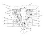
However, thelower head section 5 has a special design according to the invention. Saidlower head section 5 has a laterally displaceable head element and comprises anexterior housing 5A that is disconnectably connected to theupper head section 4, as well as acore piece 5B of annular design, whichcore piece 5B can be laterally displaced relative to thehousing 5A for centering a nozzle D of thelaser cutting head 2, and can be fixed after adjustment.
So in this version, thecore piece 5B forms the laterally displaceable head element mentioned in the introduction. In acentral aperture 6 of thecore piece 5B a cylindricalnozzle receiving device 7 is arranged which at its lower end comprises athread connection 36 with the coaxial nozzle D (FIG. 1 ).
In thelower head section 5, i.e. between thehousing 5A and thecore piece 5B, there is a cylindricalinterior space 8 for the lateral relative adjustment of thecore piece 5B (seeFIGS. 1 and 2 ), together with thenozzle receiving device 7 and the nozzle D. InFIG. 1 thenozzle receiving device 7 is positionally attached in theaperture 6 of thecore piece 5B by means of aunion nut 9 that is connected toexternal threads 10 of thecore piece 5B.
Thus, according to the invention the mutual radial/lateral position of thecore piece 5B can be adjusted together with thenozzle receiving device 7 and the nozzle D (in X-Y directions) relative to thehousing 5A for centering the nozzle D, which guides alaser beam 11 through thelaser cutting head 2, but without additional adjustment devices between the nozzle D and the work arm1 (as is the case in the state of the art).
A mirror (not shown) in theupper head section 4 is designed to reflect thelaser beam 11 along an axis A-A, whichlaser beam 11 in a centered desired position comes in along the centre of thelaser cutting head 2 and extends coaxially to a geometrical axis (designated by35) of the nozzle D (seeFIG. 1 ).
On the one hand, to fix thecore piece 5B—together with thenozzle receiving device 7 and the nozzle D—in its centered position, and on the other hand to release this affixation for a new centering/adjustment, according to the invention a specialreleasable clamping device 12 is provided. In the exemplary version, thisclamping device 12 is arranged between thehousing 5A and thecore piece 5B and in this way it makes possible a relative X-Y displacement of thecore piece 5B with thenozzle receiving device 7 and the nozzle D in thelower head section 5. However, thisclamping device 12 is constructed in such a manner that thecore piece 5B with thenozzle receiving device 7 and the nozzle D are fixed in the cuttinghead 2 during the normal cutting operation of the machine LM. This will be explained in more detail below with reference toFIG. 2 .
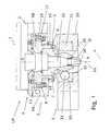
InFIG. 2 , the details of thereleasable clamping device 12 according to the invention are shown more clearly. Thisclamping device 12 makes possible, as explained above, predetermined relative X-Y displacement of thecore piece 5B, together with thenozzle receiving device 7 and the nozzle D, in thelower head section 5 during the centering step. In this exemplary version theannular space 8 is formed between anexterior mantle surface 13 of thecore piece 5B and aninterior mantle surface 14 of thehousing 5A in which, as anactuating unit 15 of theclamping device 12, preferably anannular piston 16 is arranged so as to be slidable in axial direction.
InFIG. 2 the radial play of themovable core piece 5B is designated with thereference character 17, while the axial play of theannular piston 16 is designated with thereference character 18. The values of the plays orclearances
In this version, a pneumatic working space19 is provided in theannular space 15 underneath theannular piston 16. In this case, theannular piston 16 comprises aradial exterior flange 20 and a radialinterior flange 21. Alower clamping surface 22 of theinterior flange 21 is seated on anupper clamping surface 23 of aradial exterior flange 24 of thecore piece 5B in the shown affixing home/basic position (seeFIG. 2 ). Theradial exterior flange 20 of theannular piston 16 interacts with anelastic clamping unit 25, which in this version comprises fourspring assemblies 26. Thesespring assemblies 26 are preferably designed in the form of coaxial disc springs and are preferably arranged in thehousing 5A beside theannular space 8 so as to be offset from each other by 90°.
This co-operation between the clampingunit 25 and theannular piston 16 consists of the lowermost spring element of the spring assemblies26 (seeFIG. 2 ) continuously pushing downwards an upper supportingsurface 27 of theexterior flange 20 of theannular piston 16 and in this manner forcing theannular piston 16 into its lower home position shown in which theannular piston 16 jams, i.e. fixes, thecore piece 5B, together with thenozzle receiving device 7 and the nozzle D, in its position by means of the clamping surfaces22 and23 in thelower head section 5.
If theannular piston 16 is subjected to a pressure medium—in this case to compressed air—throughholes 28 and the working space19, theannular piston 16 moves upwards in axial direction against the spring force of thespring assemblies 26 of theelastic clamping unit 25. In this way the clamping effect of the clampingunit 25 is thus determined.
In this state, the mutual position of thecore piece 5B, together with thenozzle receiving device 7 and the nozzle D, as well as of thehousing 5A in the lower head section5 (and also the position to thework arm 1, seeFIG. 1 ) can be easily and reliably centered, between the nozzle D and thework arm 1, without any additional adjusting devices by means of the existing X-Y main drives of the machine LM.
After blocking the flow of compressed air to the working space19 thespring assemblies 26 press theannular piston 16 downwards again into its home position, in which thecore piece 5B, together with thenozzle receiving device 7 and the nozzle D, is jammed or fixed again in its centered position by the clamping surfaces22 and23. In other words, this mechanism is constructed in such a manner that the movable part of the construction, i.e. in this version thecore piece 5B of thelower head section 5, during normal cutting operation of the machine LM is fixed at all times.
In a given case, according to the invention it is also possible to have such an inverse arrangement in which the laterally movable head element is formed by thehousing 5A.
Turning our attention once more toFIG. 1 , the adjustingstation 3 according to the invention is now described in more detail. As mentioned above, the adjustingstation 3 is, for example, arranged beside a cutting region, but within the effective region of the present main drives (X-Y-Z) of the laser processing machine LM and is used as a receiving device and affixation device for thenozzle receiving device 7 during centering. To this effect the adjustingstation 3 comprises a centeringsupport 29 which is preferably affixed to a frame (not illustrated) beside the work table of the machine LM. In arecess 30 of the centering support29 a receivingunit 31 is held and fixed.
The receivingunit 31 is thus used as an adjusting unit and comprises acenter hole 32 into which in the present case threerollers 33 partly reach in order to center and fix the insertednozzle receiving device 7 in the adjustingstation 3. The three centeringrollers 33 are arranged circumferentially along thehole 32, preferably so as to be offset by 120° relative to each other.
InFIG. 1 a hole of the nozzle D is designated by34 and the geometrical axis of the nozzle is designated by35, which in the centered state of the nozzle D is coaxial to the axis A-A of thelaser beam 11. The above-mentioned thread connection between the nozzle D and thenozzle receiving device 7 is designated inFIG. 1 withreference number 36.
The method of operation of the machine LM according to the invention according toFIGS. 1 and 2 is as follows:
If the nozzle D is to be adjusted or centered, thelaser cutting head 2 is moved, by means of normal adjustment of thework arm 1, to the determined position of the centeringsupport 29 in the adjustingstation 3. After this step, the clamping of thecore piece 5B, together with thenozzle receiving device 7 and the nozzle D, is released. This means that theannular piston 16 of theclamping device 12 is subjected to compressed air through theholes 28, and then theannular piston 16 moves upwards in axial direction against the spring force of theelastic clamping unit 25. In this way the clamping effect of the clampingunit 25 is thus released.
Thereafter thelower head section 5 can be moved downwards in the direction of the Z axis, wherein themovable core piece 5B of thelower head section 5 of thelaser cutting head 2—together with thenozzle receiving device 7 and the nozzle D—in its released state is vertically moved to thenozzle receiving unit 31 of the centeringsupport 29 of the adjustingstation 3, where it is received and fixed.
Any checking or adjusting thelaser beam 11 can then most easily be carried out in such a manner that from below some plastic tape (not shown) is stuck onto the underside of the nozzle D so that the briefly switched-onlaser beam 11 can penetrate it and forms a hole in it. The actual position of this hole thus formed in the plastic tape is in the simplest case visually confirmed by the operator. Thereafter the optical position of thelaser beam 11 is determined manually or automatically.
In another exemplary version of the invention the image of the hole is acquired by means of a camera module directed onto the stuck-on plastic tape (in a manner similar to that in EP-1,561,538) and is transferred as an image signal to a monitor (not shown) of the machine LM. The actual position of the hole (and indirectly also of the laser beam) is shown on the monitor preferably by means of a target.
If applicable, the hole image of thelaser beam 11 can be subjected to an image analysis and can be immediately evaluated in a computer-controlled manner or manually, and thereafter corresponding corrections of positioning are carried out. However, according to the invention, the determined offset of the optical position of thelaser beam 11 is correspondingly corrected by means of the present main axes drives X and Y of the machine LM, or by means of the CNC control system. In this way the centering process of thelaser beam 11 is completed.
Since by means of this centering method thenozzle receiving device 7, together with the nozzle D and thecore piece 5B, is fixed in the centeringsupport 29 of the adjustingstation 3, thehousing 5A of thelower head section 5 can be correctly aligned/adjusted relative to the centre and to thegeometrical axis 35 of the nozzle D by means of the main axes drives of the machine LM in the direction of the X-Y axes.
Subsequently thecore piece 5B, together with the set centered position of thenozzle receiving device 7 and of the nozzle D, is clamped again by activating theclamping device 12. After this step the entirelaser cutting head 2 can be moved by thework arm 1, from the adjustingstation 3 in the direction of the Z axis by means of the main drive. Thereafter the nozzle D is, and remains, reliably fixed in the adjusted and centered state.
For this purpose, in a manner similar to that mentioned above, the nozzle D is locked in the receivingunit 31 of the adjustingstation 3, and adjustment itself is accomplished by laterally sliding the remaining cutting head relative to the nozzle D, wherein for this purpose, however, it is necessary to release first theclamping device 12.
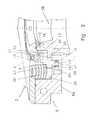
In the version shown inFIG. 3 thecamera system 37 of the adjustingstation 3 comprises
- a target (target piece)38 that is penetrated by means of a laser pulse (e.g. the target comprises a plastic film or a metal foil that is as thin as possible);
- an
absorption plate 39 that can be moved away; - a height-
adjustable camera 40 associated with a known image processing unit41 (not shown in further detail); - a
housing 42 that provides protection e.g. against dust.
As shown inFIG. 3 , thecamera system 37, which comprises thetarget 38, theremovable absorption plate 39 and the height-adjustable camera 40, is underneath the receivingunit 31 provided for fixing the nozzle D in the adjustingstation 3. Thecamera 40 is associated with theimage processing unit 41.
Before thecamera system 37 can be used, a calibration should be carried out:
- with the correctly adjusted nozzle D, a movement into the receiving
unit 31 takes place to fix the nozzle; - the
target 38 is transported into one position; - by means of a laser pulse a hole is made into the
target 38; - the
absorption plate 39 is then moved away; - the
camera 40 acquires the hole and stores its position and size; this position is stored as zero in the system; - the
absorption plate 39 is moved back into place.
- with the correctly adjusted nozzle D, a movement into the receiving
Subsequently the adjustment method is carried out as follows on the laser cutting machine LM according to the invention, as shown inFIG. 3 :
- a) the
laser cutting head 2 first moves over the receivingunit 31 of the adjustingstation 3; - b) the
clamping device 12 of thelaser cutting head 2 is then released; - c) the
laser cutting head 2 is moved into the receivingunit 31 to fix the nozzle; - d) the
clamping device 12 of thelaser cutting head 2 is locked; - e) the
target 38 is transported into a predetermined position; - f) by means of a laser pulse a hole is made in the
target 38; - g) the
absorption plate 39 is then moved away; - h) the
camera 40 acquires the size and position of the hole; - i) the
absorption plate 39 is moved back into place; - j) the position of the hole is compared to the calibration values by means of the
image processing unit 41; - k) if the position of the penetration hole does not coincide with the calibration position, the clamping
device 12 of thelaser cutting head 2 is released and the error is corrected with the main drives of the machine LM in the CNC axes; theclamping device 12 of thelaser cutting head 2 is then locked again; - l) for control purposes the above-mentioned procedure can be repeated;
- m) the
laser cutting head 2 is moved out of the receivingunit 31 of the adjustingstation 3, and thereafter normal operation of the machine LM can commence.
- a) the
In a further version, the focal position can be determined. To this effect with various focal positions holes are made in the target, which after each “firing” is displaced by one working position. The camera evaluates the holes size. In the smallest hole the focus was in the target.
The invention thus makes it possible to achieve a semi-automatic or fully automatic centering of the nozzle, for which, however, no additional servo-motors or other adjusting devices are necessary between the nozzle head and the work arm, as is the case in the state of the art. By the invention the adjustment and construction of the laser cutting machine is significantly facilitated. The solution according to the invention makes it possible, without much effort, to reliably detect any deviation of the position of the laser beam from the desired/predetermined value, and to carry out suitable, simple, fast and reproducible correction for centering.
It should be emphasized that, within the scope of protection according to the enclosed claims, further embodiments of the laser processing machine according to the invention may be carried out, for which, knowing the present disclosure of the invention, a person having ordinary skill in the art would not, however, require any further technical teaching.
For example, in thereleasable clamping device 12 theannular piston 16 could also be operated hydraulically or electro-magnetically. Thespring assemblies 26 could, if applicable, be replaced by a coil spring or other spring elements, e.g. pneumatic spring units. In a further embodiment option, thenozzle receiving device 7 and thecore piece 5B could be designed as an integrated, preferably single-part element. In this way the construction of the cuttinghead 5 could be further simplified.
The single annular piston16 (of the versions shown) could, if applicable, be replaced by piston elements or piston segments that are arranged so as to be offset along the annular gap. Furthermore, such a design is also possible in which the machine LM comprises two or more laser cutting heads2 (not illustrated).
Of course, it is also feasible for a laser cutting machine to be provided without a work table. This can apply, for example, to mobile laser cutting machines and oversize work pieces where the laser cutting machine is moved towards the work piece, wherein the work piece is affixed elsewhere, or wherein as a result of its size and weight does not require any affixation at all.
- A-A—Axis of laser beam
- D—Nozzle
- LM—Laser cutting machine
- W—Work piece to be processed
- 1—Work arm
- 2—Laser cutting head
- 3—Nozzle adjusting station
- 4—Upper head section
- 5—Lower head section
- 5A—Housing
- 5B—Core piece
- 6—Aperture
- 7—Nozzle receiving device
- 8—Cylindrical interior space
- 9—Union nut
- 10—External threads
- 11—Laser beam
- 12—Releasable clamping device
- 13—Exterior mantle surface (of the core piece)
- 14—Interior mantle surface (of the housings)
- 15—Actuating member
- 16—Annular piston
- 17—Radial play (of core piece)
- 18—Axial play (of the piston)
- 19—Working space
- 20—Exterior flange
- 21—Interior flange
- 22—Lower clamping surface (of the interior flange)
- 23—Upper clamping surface (of the exterior flange of the core piece)
- 24—Exterior flange (of the core piece)
- 25—Clamping unit
- 26—Spring assembly
- 27—Upper supporting surface (of the annular piston)
- 28—Hole (for compressed air)
- 29—Centering support
- 30—Recess
- 31—Nozzle receiving unit
- 32—Cylindrical hole
- 33—Centering roller
- 34—Nozzle hole
- 35—Geometrical axis of nozzle
- 36—Thread connection
- 37—Camera system
- 38—Target
- 39—Absorption area
- 40—Camera
- 41—Image processing unit
- 42—Housing
Claims (17)
1. A laser processing machine comprising:
a work arm;
a laser cutting head mounted on said work arm;
a nozzle receiver arranged in said work arm;
a nozzle configured to pass a laser beam, said nozzle connected to said nozzle receiver;
an alignment unit for adjusting the laser beam relative to said nozzle, said alignment unit including a head arrangement receiving said nozzle receiver;
an upper head section in said head arrangement;
a nozzle adjusting station, said nozzle adjusting station including a nozzle receiving unit configured to fix said nozzle against movement;
said alignment unit including a releasable clamping device configured to controllably release said nozzle for relative movement relative to said work arm and said laser cutting head;
laser head main drives operatively connected to controllably move said work arm and said laser cutting head relative to said nozzle when said nozzle receiving unit fixes said nozzle against movement and said clamping device releases said nozzle, said laser head main drives operatively connected to controllably move said work arm, said laser cutting head, and said nozzle for laser processing of workpieces; and,
a lower head section in said head arrangement, said lower head section including a laterally-slidable head piece connected to said nozzle receiver.
2. The laser processing machine as claimed inclaim 1 , wherein: said head piece is a cylindrical-core piece connected to said nozzle receiver.
3. A laser processing machine as claimed inclaim 1 , further comprising: said lower head section including an exterior housing operatively connected to said work arm through said upper head section, for movement with said work arm.
4. A laser processing machine as claimed inclaim 1 , further comprising: said releasable clamping device including an annular piston, said annular piston being arranged in an axially-extending annular space and being moveable between, (a) a first position in which said annular piston fixes said laterally-slidable head piece, and (b) a second position in which said annular piston releases said laterally-slidable head piece.
5. A laser processing machine as claimed inclaim 4 , further comprising:
said annular piston is pneumatically biased to said second position; and,
at least one clamping surface is connected to said annular piston to release said laterally-slidable head piece in said second position.
6. A laser processing machine as claimed inclaim 4 , further comprising:
said annular piston is spring-biased to said first position; and,
at least one clamping surface is connected to said annular piston to clamp said laterally-slidable head piece in said first position.
7. A laser processing machine as claimed inclaim 4 , further comprising:
said annular piston is pneumatically biased to said second position, and a first clamping surface is connected to said annular piston to release said laterally-slidable head piece in said second position;
said annular piston is spring-biased to said first position, and a second clamping surface is connected to said annular piston to clamp said laterally-slidable head piece in said first position; and,
an interior flange of said annular piston forms said first and second clamping surfaces.
8. A laser processing machine as claimed inclaim 7 , further comprising: said laterally-slidable head piece has an exterior flange, and said annular piston has an interior flange circumferentially spaced from said exterior flange.
9. A laser processing machine as claimed inclaim 1 , further comprising:
said releasable clamping device includes a clamping unit; and,
said clamping unit includes at least one spring unit.
10. A laser processing machine as claimed inclaim 9 , further comprising: said clamping unit includes three spring assemblies.
11. The laser processing machine as claimed inclaim 1 , wherein: said laterally-slidable head piece is arranged with a radial play having value in the range of 1.0 to 5.0 mm.
12. The laser processing machine as claimed inclaim 1 , wherein: said laterally-slidable head piece is integral with said nozzle receiver.
13. A laser processing machine as claimed inclaim 1 , further comprising: a work table for receiving material to be processed.
14. A laser processing machine as claimed inclaim 1 , further comprising:
a camera system provided underneath said nozzle receiving unit of said nozzle adjusting station, said camera system having a target for laser beam, said camera system having a removable absorption plate, and said camera system having a camera.
15. A laser processing machine as claimed inclaim 14 , further comprising: an image processing unit operatively communicating with said camera to process laser penetration hole images.
16. A laser processing machine beam alignment system comprising:
a work arm;
a laser cutting head mounted on said work arm;
a nozzle receiver arranged in said work arm;
a nozzle configured to pass a laser beam, said nozzle connected to said nozzle receiver;
an alignment unit for adjusting the laser beam relative to said nozzle, said alignment unit including a head arrangement receiving said nozzle receiver;
an upper head section in said head arrangement;
laser head main drives operatively connected to controllably move said work arm and said head arrangement in an X-Y coordinate space relative to said nozzle when said nozzle receiving unit fixes said nozzle against movement and said clamping device releases said nozzle, said laser head main drives operatively connected to controllably move said work arm, said laser cutting head, and said nozzle for laser processing of workpieces;
a nozzle adjustment station disposed in the X-Y coordinate space, said nozzle adjustment station having a nozzle receiving unit fixing said nozzle against movement in the X-Y coordinate space;
said alignment unit including a releasable clamping device configured to controllably release said head arrangement for controlled X-Y coordinate positioning alignment by said at least one main laser head drive, relative to said work arm and said nozzle fixed in said nozzle adjustment station; and
a lower head section in said head arrangement, said lower head section including a laterally-slidable head piece connected to said nozzle receiver.
17. A laser processing machine beam alignment system as claimed inclaim 16 , further comprising:
a laterally-slidable head piece included in said releasable clamping device;
said releasable clamping device including an annular piston, said annular piston being arranged in an axially-extending annular space and being moveable between, (a) a first position in which said annular piston fixes said laterally-slidable head piece, and (b) a second position in which the said annular piston releases said laterally-slidable head piece.
Priority Applications (1)
| Application Number | Priority Date | Filing Date | Title |
|---|---|---|---|
| US13/703,723US9937590B2 (en) | 2010-07-22 | 2011-07-21 | Laser processing machine |
Applications Claiming Priority (5)
| Application Number | Priority Date | Filing Date | Title |
|---|---|---|---|
| EP10170451AEP2409808A1 (en) | 2010-07-22 | 2010-07-22 | Laser processing machine |
| EP10170451 | 2010-07-22 | ||
| US37466510P | 2010-08-18 | 2010-08-18 | |
| PCT/IB2011/053257WO2012011072A1 (en) | 2010-07-22 | 2011-07-21 | Laser processing machine |
| US13/703,723US9937590B2 (en) | 2010-07-22 | 2011-07-21 | Laser processing machine |
Related Parent Applications (1)
| Application Number | Title | Priority Date | Filing Date |
|---|---|---|---|
| PCT/IB2011/053257A-371-Of-InternationalWO2012011072A1 (en) | 2010-07-22 | 2011-07-21 | Laser processing machine |
Related Child Applications (1)
| Application Number | Title | Priority Date | Filing Date |
|---|---|---|---|
| US15/892,100ContinuationUS10086475B2 (en) | 2010-07-22 | 2018-02-08 | Laser processing machine |
Publications (2)
| Publication Number | Publication Date |
|---|---|
| US20130112671A1 US20130112671A1 (en) | 2013-05-09 |
| US9937590B2true US9937590B2 (en) | 2018-04-10 |
Family
ID=43383572
Family Applications (2)
| Application Number | Title | Priority Date | Filing Date |
|---|---|---|---|
| US13/703,723Active2033-05-10US9937590B2 (en) | 2010-07-22 | 2011-07-21 | Laser processing machine |
| US15/892,100ActiveUS10086475B2 (en) | 2010-07-22 | 2018-02-08 | Laser processing machine |
Family Applications After (1)
| Application Number | Title | Priority Date | Filing Date |
|---|---|---|---|
| US15/892,100ActiveUS10086475B2 (en) | 2010-07-22 | 2018-02-08 | Laser processing machine |
Country Status (7)
| Country | Link |
|---|---|
| US (2) | US9937590B2 (en) |
| EP (2) | EP2409808A1 (en) |
| JP (1) | JP5940065B2 (en) |
| CN (1) | CN103003021B (en) |
| PL (1) | PL2595776T3 (en) |
| TR (1) | TR201808666T4 (en) |
| WO (1) | WO2012011072A1 (en) |
Cited By (1)
| Publication number | Priority date | Publication date | Assignee | Title |
|---|---|---|---|---|
| US10500690B2 (en) | 2017-10-25 | 2019-12-10 | United Technologies Corporation | Method and apparatus for aligning a process gas jet nozzle and laser machining beam |
Families Citing this family (20)
| Publication number | Priority date | Publication date | Assignee | Title |
|---|---|---|---|---|
| CA2796369A1 (en)* | 2010-04-13 | 2011-10-20 | National Research Council Of Canada | Laser processing control method |
| EP2444193A1 (en) | 2010-10-20 | 2012-04-25 | Bystronic Laser AG | Laser machining head with an outer isolated part and an inner isolated part in metal |
| EP2687317B1 (en) | 2012-07-20 | 2020-05-06 | Bystronic Laser AG | Laser processing machine, in particular laser cutting machine and method for adjusting a focused laser beam |
| EP2883647B1 (en) | 2013-12-12 | 2019-05-29 | Bystronic Laser AG | Method for configuring a laser machining device |
| WO2015194260A1 (en)* | 2014-06-18 | 2015-12-23 | 凸版印刷株式会社 | Micro-needle unit |
| WO2016031069A1 (en) | 2014-08-29 | 2016-03-03 | 三菱電機株式会社 | Laser processing machine and numerical control program creation software |
| CN106112275A (en)* | 2016-08-22 | 2016-11-16 | 苏州市华宁机械制造有限公司 | A kind of laser cutting injection nozzle tumbler |
| US10751766B2 (en)* | 2017-11-15 | 2020-08-25 | The Boeing Company | Laser ablation system having a moveable carriage with clamping system configured to clamp and seal against a workpiece |
| CN108581231A (en)* | 2018-06-28 | 2018-09-28 | 苏州天弘激光股份有限公司 | Tubing track cutting machine and its center positioning mechanism |
| WO2020024164A1 (en)* | 2018-08-01 | 2020-02-06 | 深圳配天智能技术研究院有限公司 | Calibration piece, calibration assembly and calibration system for automatic welding apparatus |
| WO2020060981A1 (en)* | 2018-09-19 | 2020-03-26 | Rendyr | Portable laser cutter |
| KR102662392B1 (en) | 2018-11-22 | 2024-05-02 | 삼성디스플레이 주식회사 | Display device and manufacturing method thereof |
| TR202011526A2 (en)* | 2020-07-20 | 2020-09-21 | Dener Makina Sanayi Ve Ticaret Ltd Sirketi | |
| WO2022108481A1 (en)* | 2020-11-20 | 2022-05-27 | Общество с ограниченной ответственностью "СПЕЦВЕНТРЕШЕНИЕ" | Laser cutting machine with spring-loaded shock absorbers |
| RU203177U1 (en)* | 2020-11-20 | 2021-03-24 | Общество с ограниченной ответственностью "СПЕЦВЕНТРЕШЕНИЕ" | LASER CUTTING MACHINE WITH SPRING DAMPER |
| RU203178U1 (en)* | 2020-11-20 | 2021-03-24 | Общество с ограниченной ответственностью "СПЕЦВЕНТРЕШЕНИЕ" | LASER CUTTING MACHINE WITH RIGID COVERING |
| RU203405U1 (en)* | 2020-11-20 | 2021-04-02 | Общество с ограниченной ответственностью "СПЕЦВЕНТРЕШЕНИЕ" | LASER CUTTING MACHINE WITH RADIATION PROTECTION DIRECTLY IN THE CUT AREA |
| CN115383331A (en)* | 2022-09-22 | 2022-11-25 | 上海工程技术大学 | Controlled-release tablet laser drilling, high-precision infrared detection device |
| CN115519265B (en)* | 2022-10-13 | 2024-07-19 | 丹阳宏图激光科技有限公司 | Laser welding tool for stainless steel handrail for high-speed rail and working method of laser welding tool |
| CN118417712B (en)* | 2024-05-07 | 2025-05-13 | 大连河野智能装备有限公司 | A fully automated laser cutting equipment |
Citations (173)
| Publication number | Priority date | Publication date | Assignee | Title |
|---|---|---|---|---|
| US3423593A (en)* | 1966-10-28 | 1969-01-21 | Bell Telephone Labor Inc | Optical beam position sensor |
| US3590840A (en)* | 1968-05-29 | 1971-07-06 | Bendix Corp | Fluidic control apparatus |
| US3692414A (en) | 1971-02-24 | 1972-09-19 | Harry L Hosterman | Non-contacting measuring probe |
| US3736402A (en)* | 1970-09-17 | 1973-05-29 | Coherent Radiation | Automated laser tool |
| US3843865A (en)* | 1971-09-14 | 1974-10-22 | G Nath | Device for material working by a laser beam,and method for its production |
| JPS5641092A (en) | 1979-09-11 | 1981-04-17 | Toshiba Corp | Laser processing device |
| US4335296A (en)* | 1979-08-21 | 1982-06-15 | C. Behrens Ag | Machine tool with a laser beam cutting device |
| US4406940A (en)* | 1980-10-23 | 1983-09-27 | Amada Engineering & Service Co., Inc. | Laser processing machine |
| US4427873A (en)* | 1982-03-18 | 1984-01-24 | Amada Engineering & Service Co. | Method and apparatus for aligning axes of assisting gas nozzles with laser beam axes in laser processing machines |
| US4634832A (en)* | 1983-04-20 | 1987-01-06 | British Shipbuilders | Laser-beamwelding |
| US4644128A (en)* | 1986-01-21 | 1987-02-17 | Benteler Corporation | Laser contour cut manifolds |
| US4668088A (en)* | 1983-02-17 | 1987-05-26 | Commissariat A L'energie Atomique | Process and apparatus for the alignment of a laser beam by using optical sighting means and process for using the apparatus for checking the alignment |
| US4675501A (en)* | 1983-10-29 | 1987-06-23 | Trumpf Gmbh & Co. | Laser apparatus with novel beam aligning means and method of laser processing of workpieces using same |
| US4698480A (en)* | 1984-03-24 | 1987-10-06 | Trumpf Gmbh & Co. | Computer controlled machine for punching and thermal cutting of workpieces |
| US4728771A (en) | 1978-01-03 | 1988-03-01 | Prima Industrie S.P.A. | Automatic cutting machine using laser ray |
| US4772772A (en) | 1986-07-11 | 1988-09-20 | Bias Forschungs und Entwicklungslabor fur Angewandte Strahtechnik GmbH | Process for the supervision of the machining process using a high-power energy source, in particular a laser, and machining optical system for carrying out the same |
| DE8710866U1 (en) | 1987-08-08 | 1988-12-08 | Robert Bosch Gmbh, 7000 Stuttgart | Workpiece processing device |
| US4806726A (en)* | 1985-10-24 | 1989-02-21 | Ap Industries, Inc. | Apparatus for machining a bent elongated member of variable configuration |
| US4940880A (en)* | 1989-09-11 | 1990-07-10 | Trumpf Gmbh & Co. | Combination punch press and laser cutting machine with laser beam generator mounted thereon |
| US4950861A (en)* | 1989-09-11 | 1990-08-21 | Trumpf Gmbh & Co. | Combination punch press and laser cutting machine with movable slag and fume collector |
| JPH0327889A (en) | 1989-06-27 | 1991-02-06 | Amada Co Ltd | Working head of laser beam machine |
| US5008510A (en)* | 1989-12-29 | 1991-04-16 | Amada Company, Limited | Laser punch press, and beam detection device for adjusting the laser beam path |
| US5039836A (en)* | 1957-06-27 | 1991-08-13 | Lemelson Jerome H | Radiation manufacturing apparatus and method |
| US5045668A (en)* | 1990-04-12 | 1991-09-03 | Armco Inc. | Apparatus and method for automatically aligning a welding device for butt welding workpieces |
| US5132510A (en)* | 1990-09-04 | 1992-07-21 | Trumpf, Inc. | Laser machine assembly for flow of workpieces therethrough and method of using same |
| DE4201640C1 (en) | 1992-01-22 | 1993-02-25 | Weidmueller Interface Gmbh & Co, 4930 Detmold, De | Nozzle for processing workpiece e.g. by laser beam - consists of nozzle body with sensor element of e.g. copper@ attached to insulating body for contactless measurement |
| US5272312A (en) | 1989-03-14 | 1993-12-21 | Jurca Marius Christian | Process for quality control of laser beam welding and cutting |
| US5304773A (en)* | 1992-02-19 | 1994-04-19 | Trumpf Inc. | Laser work station with optical sensor for calibration of guidance system |
| EP0597771A1 (en) | 1992-11-13 | 1994-05-18 | Commissariat A L'energie Atomique | Optical beam centralisation adjusting device, application to the introduction of the beam in an optical fibre |
| US5371336A (en)* | 1991-10-01 | 1994-12-06 | Messer Griesheim Gmbh | Device for contact-free data gathering from a thermal machining system |
| US5373135A (en)* | 1988-12-30 | 1994-12-13 | Fraunhofer-Gesellschaft Zur Foerderung Der Angewandten Forschung E.V. | Process and an arrangement for treating workpiece by means of laser radiation |
| JPH07144289A (en) | 1993-11-19 | 1995-06-06 | Niigata Eng Co Ltd | Method and device for centering nozzle of laser beam machine |
| US5463202A (en) | 1992-12-28 | 1995-10-31 | Mitsubishi Denki Kabushiki Kaisha | Laser machining apparatus and method |
| US5491318A (en)* | 1993-03-25 | 1996-02-13 | Mitsubishi Denki Kabushiki Kaisha | Laser cutting machine |
| US5525776A (en)* | 1991-10-17 | 1996-06-11 | Fanuc Ltd. | Compound machine tool |
| WO1997007928A2 (en) | 1995-08-31 | 1997-03-06 | Biolase Technology, Inc. | User programmable combination of atomized particles for electromagnetically induced cutting |
| JPH0976084A (en) | 1995-09-14 | 1997-03-25 | Mitsubishi Heavy Ind Ltd | Method and jig for adjusting converging head of laser beam for cutting |
| US5667707A (en)* | 1994-05-02 | 1997-09-16 | Trumpf Gmbh & Co. | Laser cutting machine with focus maintaining beam delivery |
| US5685999A (en)* | 1994-09-21 | 1997-11-11 | Dr. Klaus Barthel Sensorsysteme Gmbh | Compact laser machining head with integrated on-line path control for laser machining of material |
| US5698120A (en)* | 1995-01-17 | 1997-12-16 | Mitsubishi Denki Kabushiki Kaisha | Laser machining system with control based on machining state recognition |
| US5751436A (en)* | 1996-12-23 | 1998-05-12 | Rocky Mountain Instrument Company | Method and apparatus for cylindrical coordinate laser engraving |
| JPH10249566A (en) | 1997-03-10 | 1998-09-22 | Amada Co Ltd | Laser beam machining method and its device |
| JPH1177356A (en) | 1997-09-05 | 1999-03-23 | Amada Co Ltd | Centering method and device for automatic laser beam machining |
| US5886319A (en)* | 1992-08-05 | 1999-03-23 | Loughborough University Innovations Limited | Automatic operations on materials |
| US5915316A (en)* | 1995-01-13 | 1999-06-29 | Tokai Kogyo Mishin Kabushiki Kaisha | Embroidering and laser processing machine |
| US5969335A (en)* | 1996-09-20 | 1999-10-19 | Matsushita Electric Industrial Co., Ltd. | Laser control system for use in laser processing machine utilizing laser-induced plasma detecting system |
| US5968382A (en)* | 1995-07-14 | 1999-10-19 | Hitachi, Ltd. | Laser cleavage cutting method and system |
| US5998768A (en)* | 1997-08-07 | 1999-12-07 | Massachusetts Institute Of Technology | Active thermal control of surfaces by steering heating beam in response to sensed thermal radiation |
| US6031200A (en) | 1997-08-04 | 2000-02-29 | Data Technology, Inc. | In-process kerf measurement system |
| US6040549A (en) | 1994-02-28 | 2000-03-21 | Mitsubishi Denki Kabushiki Kaisha | Laser beam machining apparatus and corresponding method which employs a laser beam to pretreat and machine a workpiece |
| US6044308A (en)* | 1997-06-13 | 2000-03-28 | Huissoon; Jan Paul | Method and device for robot tool frame calibration |
| US6124565A (en)* | 1998-04-13 | 2000-09-26 | Yamazaki Mazak Kabushiki Kaisha | Laser cutting machine |
| US6188041B1 (en)* | 1998-11-13 | 2001-02-13 | Korea Atomic Energy Research Institute | Method and apparatus for real-time weld process monitoring in a pulsed laser welding |
| US6204473B1 (en)* | 1999-04-30 | 2001-03-20 | W.A. Whitney Co. | Laser-equipped machine tool cutting head with pressurized counterbalance |
| US6260976B1 (en)* | 1997-06-24 | 2001-07-17 | Mitsubishi Denki Kabushiki Kaisha | Laser beam collimation apparatus and laser processing machine using same |
| US6284999B1 (en)* | 1999-07-23 | 2001-09-04 | Lillbacka Jetair Oy | Laser cutting system |
| US6288363B1 (en)* | 1992-10-23 | 2001-09-11 | Mitsubishi Denki Kabushiki Kaisha | Machining head and laser machining apparatus |
| US6300592B1 (en)* | 1999-07-23 | 2001-10-09 | Lillbacka Jetair Oy | Laser cutting system |
| US6316743B1 (en)* | 1998-09-09 | 2001-11-13 | Tanaka Engineering Works, Ltd. | Laser piercing method, laser processing nozzle, and laser cutting apparatus |
| US6326586B1 (en)* | 1999-07-23 | 2001-12-04 | Lillbacka Jetair Oy | Laser cutting system |
| US6376798B1 (en)* | 1999-07-23 | 2002-04-23 | Lillbacka Jetair Oy | Laser cutting system |
| US6392192B1 (en)* | 1999-09-15 | 2002-05-21 | W. A. Whitney Co. | Real time control of laser beam characteristics in a laser-equipped machine tool |
| US6393687B1 (en)* | 1999-03-11 | 2002-05-28 | Deckel Maho Gmbh | Machine tool for the processing of workpieces with cutting tool and laser beam |
| US6417487B2 (en)* | 1998-06-08 | 2002-07-09 | Mitsubishi Heavy Industries, Ltd. | Laser beam machining head |
| US6419146B1 (en)* | 1996-01-12 | 2002-07-16 | The Boeing Company | Metal sandwich structure with integral hardpoint |
| US6455807B1 (en)* | 2000-06-26 | 2002-09-24 | W.A. Whitney Co. | Method and apparatus for controlling a laser-equipped machine tool to prevent self-burning |
| WO2002080081A1 (en) | 2001-03-29 | 2002-10-10 | Lasx Industries, Inc. | Controller for a laser using predictive models of materials processing |
| US20020177288A1 (en) | 1998-10-23 | 2002-11-28 | Brown Michael G. | Semiconductor device separation using a patterned laser projection |
| WO2002100587A1 (en) | 2001-06-08 | 2002-12-19 | Electro Scientific Industries, Inc. | Laser segmented cutting |
| WO2003002289A1 (en) | 2001-06-28 | 2003-01-09 | Electro Scientific Industries, Inc. | Multistep laser processing of wafers supporting surface device layers |
| US20030006221A1 (en) | 2001-07-06 | 2003-01-09 | Minghui Hong | Method and apparatus for cutting a multi-layer substrate by dual laser irradiation |
| US20030014895A1 (en)* | 1999-10-08 | 2003-01-23 | Lizotte Todd E. | Control system for ablating high-density array of vias or indentation in surface of object |
| US6528762B2 (en)* | 2001-02-12 | 2003-03-04 | W. A. Whitney Co. | Laser beam position control apparatus for a CNC laser equipped machine tool |
| DE10150129C1 (en) | 2001-10-11 | 2003-04-17 | Siemens Ag | Calibration method for laser machining device compares actual pattern described by laser beam with required pattern for correction of beam deflection unit |
| US6588738B1 (en)* | 1999-07-23 | 2003-07-08 | Lillbacka Jetair Oy | Laser cutting system |
| US20030183608A1 (en)* | 2002-03-28 | 2003-10-02 | Fanuc Ltd. | Laser machining method and apparatus therefor |
| US20030192865A1 (en) | 2002-04-16 | 2003-10-16 | W.A. Whitney Co. | Method and apparatus for laser piercing and cutting metal sheet and plate |
| US20030204283A1 (en) | 2000-04-10 | 2003-10-30 | Picard Tate S. | Centralized control architecture for a laser materials processing system |
| US6649866B2 (en)* | 2001-05-07 | 2003-11-18 | Jenoptik Automatisierungstechnik Gmbh | Tool head for laser machining of materials |
| US20030234243A1 (en)* | 2002-06-20 | 2003-12-25 | Mccoy Edward D. | Multi-axis laser apparatus and process for the fine cutting of tubing |
| US6670574B1 (en)* | 2002-07-31 | 2003-12-30 | Unitek Miyachi Corporation | Laser weld monitor |
| US20040029362A1 (en) | 2002-06-10 | 2004-02-12 | New Wave Research | Method and apparatus for cutting devices from substrates |
| US20040027630A1 (en)* | 1999-10-08 | 2004-02-12 | Lizotte Todd E. | Method and apparatus for reading firearm microstamping |
| US6693256B2 (en)* | 2001-05-08 | 2004-02-17 | Koike Sanso Kogyo Co., Ltd. | Laser piercing method |
| EP0991493B1 (en) | 1997-06-24 | 2004-07-28 | AMADA COMPANY, Ltd. | Support system for laser beam machine, and laser beam machine including the same |
| US6777646B2 (en)* | 2001-07-27 | 2004-08-17 | Precitec Kg | Laser machining head for machining a workpiece by means of a laser beam |
| US20040182998A1 (en)* | 2003-03-18 | 2004-09-23 | Denney Paul E. | Method and apparatus for detecting embedded rebar within an interaction region of a structure irradiated with laser light |
| US20040182842A1 (en)* | 2003-03-18 | 2004-09-23 | Denney Paul E. | Laser head for irradiation and removal of material from a surface of a structure |
| US20040182841A1 (en)* | 2003-03-18 | 2004-09-23 | Denney Paul E. | Laser manipulation system for controllably moving a laser head for irradiation and removal of material from a surface of a structure |
| US20040182840A1 (en)* | 2003-03-18 | 2004-09-23 | Denney Paul E. | Method and apparatus for material processing |
| US20040182839A1 (en)* | 2003-03-18 | 2004-09-23 | Denney Paul E. | Containment plenum for laser irradiation and removal of material from a surface of a structure |
| US6822187B1 (en)* | 1998-09-09 | 2004-11-23 | Gsi Lumonics Corporation | Robotically operated laser head |
| US20050017156A1 (en) | 2001-03-29 | 2005-01-27 | Gsi Lumonics Corporation | High-speed, precision, laser-based method and system for processing material of one or more targets within a field |
| US20050051523A1 (en)* | 2003-09-09 | 2005-03-10 | W.A. Whitney Co. | Laser machine tool with image sensor for registration of workhead guidance system |
| US20050062583A1 (en) | 2002-03-22 | 2005-03-24 | Gsi Lumonics Corporation | Drift-sensitive laser trimming of circuit elements |
| US20050098547A1 (en) | 2001-07-26 | 2005-05-12 | Cali Douglas S. | Method of cutting material for use in implantable medical device |
| US20050109738A1 (en) | 2003-11-21 | 2005-05-26 | Hewett Roger W. | Color coding of plasma arc torch parts and part sets |
| US20050167403A1 (en) | 2002-04-19 | 2005-08-04 | Fraunhofer-Gesellschaft Zur Forderung Der Angewandten Forschung E.V. | Laser material machining using hybrid processes |
| EP1561538A1 (en) | 2004-02-05 | 2005-08-10 | Messer Cutting & Welding GmbH | Device for adjusting the centering and focusing of a laser beam in a laser processing machine |
| US6934014B1 (en)* | 1999-10-13 | 2005-08-23 | Myos My Optical System Gmbh | Device with at least one light source, comprising several individual light sources |
| US20050213881A1 (en)* | 2002-06-27 | 2005-09-29 | Pascal Leclerc | Device for automatic centering of a laser beam and method for making same |
| EP1600248A2 (en) | 2004-05-26 | 2005-11-30 | Yamazaki Mazak Corporation | Nozzle presetter for laser machining tool of laser beam machine |
| US20060049158A1 (en) | 2004-08-13 | 2006-03-09 | Precitec Kg. | Method and apparatus for regulating an automatic treatment process |
| EP1634673A1 (en) | 2003-04-25 | 2006-03-15 | Nitto Denko Corporation | Method of producing laser-processed product and adhesive sheet, for laser processing used therefor |
| WO2006031577A2 (en) | 2004-09-13 | 2006-03-23 | Electro Scientific Industries, Inc. | Reduction of thermoelectric effects during laser trimming of resistors |
| EP1693141A2 (en) | 2004-10-20 | 2006-08-23 | Fraunhofer-Gesellschaft zur Förderung der angewandten Forschung e.V. | Arrangement and process for localised temperature measurement in a laser treatment process |
| US7124420B2 (en)* | 2002-10-08 | 2006-10-17 | Pioneer Corporation | Pickup device having a heat-radiation path |
| WO2006138605A2 (en) | 2005-06-17 | 2006-12-28 | Edw. C. Levy Co. | Apparatus and method for shaping slabs of material |
| KR100699247B1 (en) | 2006-11-21 | 2007-03-28 | 주식회사 고려반도체시스템 | Parameter conversion method of wafer laser sawing device and device therefor |
| US20070075060A1 (en) | 2005-09-30 | 2007-04-05 | Shedlov Matthew S | Method of manufacturing a medical device from a workpiece using a pulsed beam of radiation or particles having an adjustable pulse frequency |
| US20070075050A1 (en) | 2005-06-30 | 2007-04-05 | Jon Heyl | Semiconductor failure analysis tool |
| US20070088409A1 (en) | 2005-10-14 | 2007-04-19 | Carl Zeiss Meditec Ag | Device and method for material processing by means of laser radiation |
| US20070119829A1 (en)* | 2003-12-10 | 2007-05-31 | Vietz Gmbh | Orbital welding device for pipeline construction |
| US20070193987A1 (en) | 2004-03-23 | 2007-08-23 | Mark Bischoff | Material Machining Device And Method |
| US20070193988A1 (en)* | 2004-04-08 | 2007-08-23 | 3D Industrie (Sas) | Laser Cutting Machine For Trimming, Adding, Punching Or Similar Comprising A Support For The Removable Laser Head Of A Machine Tool Bed |
| US20070228025A1 (en)* | 2004-09-04 | 2007-10-04 | Trumpf Werkzeugmaschinen Gmbh + Co. Kg | Determining the relative positions of the axes of a laser machining beam and a process gas jet |
| US20070284345A1 (en) | 2006-06-08 | 2007-12-13 | Ando Syuji | Semiconductor cutting device, semiconductor cutting method, semiconductor cutting system, laser cutting device and laser cutting method |
| US20080000888A1 (en) | 2004-10-27 | 2008-01-03 | Wolfgang Schulz | Method for Cutting Materials Using a Laser Beam |
| US20080031298A1 (en)* | 2004-10-07 | 2008-02-07 | Sango Co., Ltd. | Laser Processing Deivce |
| WO2008052591A1 (en) | 2006-11-04 | 2008-05-08 | Trumpf Werkzeugmaschinen Gmbh + Co.Kg | Method and device for process monitoring during the working of a material |
| US7379483B2 (en)* | 2003-03-18 | 2008-05-27 | Loma Linda University Medical Center | Method and apparatus for material processing |
| US7407861B2 (en) | 2002-03-27 | 2008-08-05 | Gsi Group Corporation | Method and system for high-speed, precise micromachining an array of devices |
| US20080212623A1 (en) | 2005-10-14 | 2008-09-04 | Mark Bischoff | Device and method for material processing by means of laser radiation |
| EP1967316A1 (en) | 2007-03-05 | 2008-09-10 | Air Liquide Welding France | Installation and process for controlling the centering of a laser beam passing through a laser nozzle |
| DE102007013623A1 (en) | 2007-03-21 | 2008-10-02 | Trumpf Werkzeugmaschinen Gmbh + Co. Kg | Method for aligning a laser beam passing through an opening of a bore of a laser processing nozzle on a laser processing head comprises activating the beam with a defined energy, passing the beam along a first line and further processing |
| US20090001063A1 (en)* | 2005-05-31 | 2009-01-01 | Trumpf Werkzeugmaschinen Gmbh + Co. Kg | Laser processing machine with laser processing nozzle adjustment |
| WO2009007708A2 (en) | 2007-07-09 | 2009-01-15 | The University Of Manchester | Laser cutting |
| WO2009014307A1 (en) | 2007-07-24 | 2009-01-29 | Eo Technics Co., Ltd. | Laser processing apparatus and method using beam split |
| US20090057283A1 (en)* | 2007-08-03 | 2009-03-05 | Trumpf Werkzeugmaschinen Gmbh + Co. Kg | Laser Processing Machines and Methods of Processing Workpieces |
| CN201220326Y (en) | 2008-06-25 | 2009-04-15 | 深圳市大族激光科技股份有限公司 | Auxiliary device of laser cutting head |
| DE102007048471A1 (en) | 2007-10-09 | 2009-04-23 | Trumpf Laser- Und Systemtechnik Gmbh | Method for determining a position of a focused laser beam stepping through an opening of a nozzle body of a laser processing nozzle, relative to the opening, comprises moving the nozzle body and the laser beam relative to each other |
| JP2009129513A (en) | 2007-11-26 | 2009-06-11 | Sony Corp | Standard original disk and centering-adjustment method |
| US20090152249A1 (en) | 2007-12-17 | 2009-06-18 | John Patrick Petro | Apparatus and Method for Constructing Three-Dimensional Laminated Shapes for Field Pole Structures |
| US20090181838A1 (en)* | 2008-01-12 | 2009-07-16 | Trumpf Werkzeugmaschinen Gmbh + Co. Kg | Laser nozzle changing device |
| US7570443B2 (en)* | 2003-09-19 | 2009-08-04 | Applied Biosystems, Llc | Optical camera alignment |
| US20090240368A1 (en) | 2008-03-24 | 2009-09-24 | Hypertherm, Inc. | Method and Apparatus for Operating an Automated High Temperature Thermal Cutting System |
| WO2009157034A1 (en) | 2008-06-27 | 2009-12-30 | Livio Campana | Control device for machine tool for laser cutting |
| US20100044353A1 (en) | 2006-10-30 | 2010-02-25 | Flemming Ove Elholm Olsen | Method and system for laser processing |
| US20100071220A1 (en)* | 2008-09-21 | 2010-03-25 | Thompson Charles C | Laser Centering Tool |
| EP2169491A1 (en) | 2008-09-27 | 2010-03-31 | Trumpf Werkzeugmaschinen GmbH + Co. KG | Support system and method for optimising process parameters and/or regulating parameters |
| DE102008052592A1 (en) | 2008-10-21 | 2010-04-22 | Trumpf Werkzeugmaschinen Gmbh + Co. Kg | Apparatus and method for controlling a processing plant |
| DE102009044751A1 (en) | 2008-12-04 | 2010-06-10 | Highyag Lasertechnologie Gmbh | Mirror optics for use in laser working optics of laser radiation formation optical system for laser machining application, has mirrors arranged on collimated laser beam, where opening angle of divergent laser beam is achieved by equation |
| US20100176103A1 (en) | 2007-05-25 | 2010-07-15 | Fraunhofer-Gesellschaft Zur Foerderung Der Angewan | Method for material removal and device for carrying out said method |
| US20100188669A1 (en)* | 2009-01-29 | 2010-07-29 | Michael Charles Rushford | Laser beam centering and pointing system |
| EP2243557A1 (en) | 2009-04-20 | 2010-10-27 | Lumson S.p.A. | Device for containing fluid substances under airtight conditions and for dispensing them |
| US7848552B2 (en) | 2004-05-11 | 2010-12-07 | P.A.L.M. Microlaser Technologies Gmbh | Method for processing a material by means of a laser irradiation and control system |
| WO2011035888A1 (en) | 2009-09-22 | 2011-03-31 | Precitec Kg | Laser machining head having a focal position adjustment unit, and a system and a method for adjusting a focal position of a laser beam |
| WO2011051567A2 (en) | 2009-10-28 | 2011-05-05 | Lappeenrannan Teknillinen Yliopisto | Method for machining material by a laser device |
| CN102117053A (en) | 2010-12-20 | 2011-07-06 | 山西飞虹激光科技有限公司 | Intelligent computer numerical control system for laser cutter |
| WO2011083205A1 (en) | 2010-01-08 | 2011-07-14 | Lappeenrannan Teknillinen Yliopisto | Method for machining material by a laser device |
| WO2011083087A1 (en) | 2010-01-08 | 2011-07-14 | Precitec Kg | Method for processing workpieces by means of a cognitive processing head and a cognitive processing head using the same |
| US8049132B2 (en) | 2005-02-25 | 2011-11-01 | SNECMA et SNECMA Services | Method of repairing a blisk and test pieces by welding |
| US20110287607A1 (en) | 2010-04-02 | 2011-11-24 | Electro Scientific Industries, Inc. | Method and apparatus for improved wafer singulation |
| WO2012000995A1 (en) | 2010-06-30 | 2012-01-05 | Trumpf Werkzeugmaschinen Gmbh + Co. Kg | Dialogue system and method for examining a machining process |
| USRE43400E1 (en) | 2000-09-20 | 2012-05-22 | Electro Scientific Industries, Inc. | Laser segmented cutting, multi-step cutting, or both |
| US8198566B2 (en) | 2006-05-24 | 2012-06-12 | Electro Scientific Industries, Inc. | Laser processing of workpieces containing low-k dielectric material |
| US20120145687A1 (en) | 2010-12-10 | 2012-06-14 | Wolfel Mathias | Apparatus and method for operating a laser materials processing and measurement device |
| WO2012080883A1 (en) | 2010-12-16 | 2012-06-21 | Bystronic Laser Ag | Laser beam machining device and a process of laser machining comprising a single lens for light focussing |
| US8314361B2 (en)* | 2008-06-12 | 2012-11-20 | Trumpf Sachsen Gmbh | Device for laser machining |
| US8338743B2 (en) | 2007-02-19 | 2012-12-25 | Fraunhofer-Gesellschaft Zur Foerderung Der Angewandten Forschung E.V. | Method and device for controlling robots for welding workpieces |
| CN102855326A (en) | 2012-09-14 | 2013-01-02 | 山东省计算中心 | Managing method of laser cutting technological parameters |
| US8383980B2 (en)* | 2008-10-20 | 2013-02-26 | Yamazaki Mazak Corporation | Laser processing machine having programmable focus positioning function |
| US20130068738A1 (en) | 2010-05-11 | 2013-03-21 | Precitec Kg | Laser cutting head and method for cutting a workpiece by means of a laser cutting head |
| EP1574485B1 (en) | 2004-03-13 | 2013-03-27 | Schott AG | Process for free-form cutting bent substrates of brittle material |
| US8439811B2 (en)* | 2008-01-12 | 2013-05-14 | Trumpf Maschinen Ag | Laser nozzle changing device |
| US20130126489A1 (en) | 2011-11-23 | 2013-05-23 | Highcon Systems Ltd | Cardboard-handling system and method |
| US20130134141A1 (en) | 2011-11-30 | 2013-05-30 | Board Of Trustees Of Northern Illinois University | Laser assisted machining system for ceramics and hard materials |
| US20130146569A1 (en) | 2011-12-13 | 2013-06-13 | Hypertherm, Inc. | Optimization and control of beam quality for material processing |
| US20130184839A1 (en) | 2010-06-30 | 2013-07-18 | Trumpf Werkzeugmaschinen Gmbh + Co. Kg | Dialogue System and Method for Examining a Machining Process |
| US20130319980A1 (en) | 2011-02-07 | 2013-12-05 | Trumpf Werkzeugmaschinen Gmbh + Co. Kg | Device and Method for Monitoring a Laser Cutting Process |
| US20140034614A1 (en) | 2011-04-21 | 2014-02-06 | Adige S.P.A. | Methods for controlling laser cutting processes and laser cutting systems implementing same |
| US8710398B2 (en) | 2010-05-19 | 2014-04-29 | Joining Technologies, Inc. | Method and apparatus for laser strip splicing |
| US20150069028A1 (en) | 2005-04-13 | 2015-03-12 | Applied Materials, Inc. | Annealing apparatus using two wavelengths of radiation |
Family Cites Families (10)
| Publication number | Priority date | Publication date | Assignee | Title |
|---|---|---|---|---|
| JP2506755B2 (en)* | 1987-04-27 | 1996-06-12 | 豊田工機株式会社 | Laser processing torch |
| US4782496A (en)* | 1987-11-05 | 1988-11-01 | United Technologies Corporation | Breakaway nozzle for a laser processing machine |
| US5536916A (en)* | 1994-09-30 | 1996-07-16 | Sanyo Machine Works, Ltd. | Method for performing automatic alignment-adjustment of laser robot and the device |
| EP0937532B1 (en)* | 1998-02-19 | 2002-11-06 | M J Technologies Limited | Laser drilling with optical feedback |
| US6580053B1 (en)* | 2000-08-31 | 2003-06-17 | Sharp Laboratories Of America, Inc. | Apparatus to control the amount of oxygen incorporated into polycrystalline silicon film during excimer laser processing of silicon films |
| US20070151958A1 (en)* | 2002-12-19 | 2007-07-05 | Modra Christopher M | Laser cutting apparatus |
| US7619180B2 (en)* | 2003-06-25 | 2009-11-17 | Reinhard Diem | Laser head of a laser beam processing machine comprising alternating nozzles |
| GB2406068B (en)* | 2003-09-20 | 2006-04-12 | Rolls Royce Plc | Laser drilling |
| WO2010091106A1 (en)* | 2009-02-03 | 2010-08-12 | Abbott Cardiovascular Systems Inc. | Improved laser cutting system |
| KR101097331B1 (en)* | 2010-01-28 | 2011-12-23 | 삼성모바일디스플레이주식회사 | Manufacturing method of mask for depositing thin film on substrate |
- 2010
- 2010-07-22EPEP10170451Apatent/EP2409808A1/ennot_activeWithdrawn
- 2011
- 2011-07-21TRTR2018/08666Tpatent/TR201808666T4/enunknown
- 2011-07-21JPJP2013520276Apatent/JP5940065B2/enactiveActive
- 2011-07-21USUS13/703,723patent/US9937590B2/enactiveActive
- 2011-07-21EPEP11751945.4Apatent/EP2595776B1/enactiveActive
- 2011-07-21WOPCT/IB2011/053257patent/WO2012011072A1/enactiveApplication Filing
- 2011-07-21CNCN201180035170.8Apatent/CN103003021B/enactiveActive
- 2011-07-21PLPL11751945Tpatent/PL2595776T3/enunknown
- 2018
- 2018-02-08USUS15/892,100patent/US10086475B2/enactiveActive
Patent Citations (223)
| Publication number | Priority date | Publication date | Assignee | Title |
|---|---|---|---|---|
| US5039836A (en)* | 1957-06-27 | 1991-08-13 | Lemelson Jerome H | Radiation manufacturing apparatus and method |
| US3423593A (en)* | 1966-10-28 | 1969-01-21 | Bell Telephone Labor Inc | Optical beam position sensor |
| US3590840A (en)* | 1968-05-29 | 1971-07-06 | Bendix Corp | Fluidic control apparatus |
| US3736402A (en)* | 1970-09-17 | 1973-05-29 | Coherent Radiation | Automated laser tool |
| US3692414A (en) | 1971-02-24 | 1972-09-19 | Harry L Hosterman | Non-contacting measuring probe |
| US3843865A (en)* | 1971-09-14 | 1974-10-22 | G Nath | Device for material working by a laser beam,and method for its production |
| US4728771A (en) | 1978-01-03 | 1988-03-01 | Prima Industrie S.P.A. | Automatic cutting machine using laser ray |
| US4335296A (en)* | 1979-08-21 | 1982-06-15 | C. Behrens Ag | Machine tool with a laser beam cutting device |
| JPS5641092A (en) | 1979-09-11 | 1981-04-17 | Toshiba Corp | Laser processing device |
| US4406940A (en)* | 1980-10-23 | 1983-09-27 | Amada Engineering & Service Co., Inc. | Laser processing machine |
| US4427873A (en)* | 1982-03-18 | 1984-01-24 | Amada Engineering & Service Co. | Method and apparatus for aligning axes of assisting gas nozzles with laser beam axes in laser processing machines |
| US4668088A (en)* | 1983-02-17 | 1987-05-26 | Commissariat A L'energie Atomique | Process and apparatus for the alignment of a laser beam by using optical sighting means and process for using the apparatus for checking the alignment |
| US4634832A (en)* | 1983-04-20 | 1987-01-06 | British Shipbuilders | Laser-beamwelding |
| US4675501A (en)* | 1983-10-29 | 1987-06-23 | Trumpf Gmbh & Co. | Laser apparatus with novel beam aligning means and method of laser processing of workpieces using same |
| US4698480A (en)* | 1984-03-24 | 1987-10-06 | Trumpf Gmbh & Co. | Computer controlled machine for punching and thermal cutting of workpieces |
| US4806726A (en)* | 1985-10-24 | 1989-02-21 | Ap Industries, Inc. | Apparatus for machining a bent elongated member of variable configuration |
| US4644128A (en)* | 1986-01-21 | 1987-02-17 | Benteler Corporation | Laser contour cut manifolds |
| US4772772A (en) | 1986-07-11 | 1988-09-20 | Bias Forschungs und Entwicklungslabor fur Angewandte Strahtechnik GmbH | Process for the supervision of the machining process using a high-power energy source, in particular a laser, and machining optical system for carrying out the same |
| DE8710866U1 (en) | 1987-08-08 | 1988-12-08 | Robert Bosch Gmbh, 7000 Stuttgart | Workpiece processing device |
| US5373135A (en)* | 1988-12-30 | 1994-12-13 | Fraunhofer-Gesellschaft Zur Foerderung Der Angewandten Forschung E.V. | Process and an arrangement for treating workpiece by means of laser radiation |
| US5272312A (en) | 1989-03-14 | 1993-12-21 | Jurca Marius Christian | Process for quality control of laser beam welding and cutting |
| JPH0327889A (en) | 1989-06-27 | 1991-02-06 | Amada Co Ltd | Working head of laser beam machine |
| US4940880A (en)* | 1989-09-11 | 1990-07-10 | Trumpf Gmbh & Co. | Combination punch press and laser cutting machine with laser beam generator mounted thereon |
| US4950861A (en)* | 1989-09-11 | 1990-08-21 | Trumpf Gmbh & Co. | Combination punch press and laser cutting machine with movable slag and fume collector |
| US5008510A (en)* | 1989-12-29 | 1991-04-16 | Amada Company, Limited | Laser punch press, and beam detection device for adjusting the laser beam path |
| US5045668A (en)* | 1990-04-12 | 1991-09-03 | Armco Inc. | Apparatus and method for automatically aligning a welding device for butt welding workpieces |
| US5132510A (en)* | 1990-09-04 | 1992-07-21 | Trumpf, Inc. | Laser machine assembly for flow of workpieces therethrough and method of using same |
| US5371336A (en)* | 1991-10-01 | 1994-12-06 | Messer Griesheim Gmbh | Device for contact-free data gathering from a thermal machining system |
| US5525776A (en)* | 1991-10-17 | 1996-06-11 | Fanuc Ltd. | Compound machine tool |
| DE4201640C1 (en) | 1992-01-22 | 1993-02-25 | Weidmueller Interface Gmbh & Co, 4930 Detmold, De | Nozzle for processing workpiece e.g. by laser beam - consists of nozzle body with sensor element of e.g. copper@ attached to insulating body for contactless measurement |
| US5304773A (en)* | 1992-02-19 | 1994-04-19 | Trumpf Inc. | Laser work station with optical sensor for calibration of guidance system |
| US5886319A (en)* | 1992-08-05 | 1999-03-23 | Loughborough University Innovations Limited | Automatic operations on materials |
| US6288363B1 (en)* | 1992-10-23 | 2001-09-11 | Mitsubishi Denki Kabushiki Kaisha | Machining head and laser machining apparatus |
| US5463215A (en)* | 1992-11-13 | 1995-10-31 | Commissariat A L'energie Atomique | Device for aligning the axis of a light beam with the axis of an optical fiber |
| EP0597771A1 (en) | 1992-11-13 | 1994-05-18 | Commissariat A L'energie Atomique | Optical beam centralisation adjusting device, application to the introduction of the beam in an optical fibre |
| US5463202A (en) | 1992-12-28 | 1995-10-31 | Mitsubishi Denki Kabushiki Kaisha | Laser machining apparatus and method |
| US5491318A (en)* | 1993-03-25 | 1996-02-13 | Mitsubishi Denki Kabushiki Kaisha | Laser cutting machine |
| US5548098A (en)* | 1993-03-25 | 1996-08-20 | Mitsubishi Denki Kabushiki Kaisha | Laser cutting machine |
| JPH07144289A (en) | 1993-11-19 | 1995-06-06 | Niigata Eng Co Ltd | Method and device for centering nozzle of laser beam machine |
| US6040549A (en) | 1994-02-28 | 2000-03-21 | Mitsubishi Denki Kabushiki Kaisha | Laser beam machining apparatus and corresponding method which employs a laser beam to pretreat and machine a workpiece |
| EP0680805B1 (en) | 1994-05-02 | 2001-01-31 | Trumpf GmbH & Co | Laser cutting machine with focus position adjustment |
| US5667707A (en)* | 1994-05-02 | 1997-09-16 | Trumpf Gmbh & Co. | Laser cutting machine with focus maintaining beam delivery |
| US5685999A (en)* | 1994-09-21 | 1997-11-11 | Dr. Klaus Barthel Sensorsysteme Gmbh | Compact laser machining head with integrated on-line path control for laser machining of material |
| US5915316A (en)* | 1995-01-13 | 1999-06-29 | Tokai Kogyo Mishin Kabushiki Kaisha | Embroidering and laser processing machine |
| US5698120A (en)* | 1995-01-17 | 1997-12-16 | Mitsubishi Denki Kabushiki Kaisha | Laser machining system with control based on machining state recognition |
| US5968382A (en)* | 1995-07-14 | 1999-10-19 | Hitachi, Ltd. | Laser cleavage cutting method and system |
| WO1997007928A2 (en) | 1995-08-31 | 1997-03-06 | Biolase Technology, Inc. | User programmable combination of atomized particles for electromagnetically induced cutting |
| JPH0976084A (en) | 1995-09-14 | 1997-03-25 | Mitsubishi Heavy Ind Ltd | Method and jig for adjusting converging head of laser beam for cutting |
| US6419146B1 (en)* | 1996-01-12 | 2002-07-16 | The Boeing Company | Metal sandwich structure with integral hardpoint |
| US5969335A (en)* | 1996-09-20 | 1999-10-19 | Matsushita Electric Industrial Co., Ltd. | Laser control system for use in laser processing machine utilizing laser-induced plasma detecting system |
| US5751436A (en)* | 1996-12-23 | 1998-05-12 | Rocky Mountain Instrument Company | Method and apparatus for cylindrical coordinate laser engraving |
| JPH10249566A (en) | 1997-03-10 | 1998-09-22 | Amada Co Ltd | Laser beam machining method and its device |
| US6044308A (en)* | 1997-06-13 | 2000-03-28 | Huissoon; Jan Paul | Method and device for robot tool frame calibration |
| EP0991493B1 (en) | 1997-06-24 | 2004-07-28 | AMADA COMPANY, Ltd. | Support system for laser beam machine, and laser beam machine including the same |
| US6260976B1 (en)* | 1997-06-24 | 2001-07-17 | Mitsubishi Denki Kabushiki Kaisha | Laser beam collimation apparatus and laser processing machine using same |
| US6031200A (en) | 1997-08-04 | 2000-02-29 | Data Technology, Inc. | In-process kerf measurement system |
| US5998768A (en)* | 1997-08-07 | 1999-12-07 | Massachusetts Institute Of Technology | Active thermal control of surfaces by steering heating beam in response to sensed thermal radiation |
| JPH1177356A (en) | 1997-09-05 | 1999-03-23 | Amada Co Ltd | Centering method and device for automatic laser beam machining |
| US6124565A (en)* | 1998-04-13 | 2000-09-26 | Yamazaki Mazak Kabushiki Kaisha | Laser cutting machine |
| US6417487B2 (en)* | 1998-06-08 | 2002-07-09 | Mitsubishi Heavy Industries, Ltd. | Laser beam machining head |
| US6822187B1 (en)* | 1998-09-09 | 2004-11-23 | Gsi Lumonics Corporation | Robotically operated laser head |
| US6316743B1 (en)* | 1998-09-09 | 2001-11-13 | Tanaka Engineering Works, Ltd. | Laser piercing method, laser processing nozzle, and laser cutting apparatus |
| US20020177288A1 (en) | 1998-10-23 | 2002-11-28 | Brown Michael G. | Semiconductor device separation using a patterned laser projection |
| US6188041B1 (en)* | 1998-11-13 | 2001-02-13 | Korea Atomic Energy Research Institute | Method and apparatus for real-time weld process monitoring in a pulsed laser welding |
| US6393687B1 (en)* | 1999-03-11 | 2002-05-28 | Deckel Maho Gmbh | Machine tool for the processing of workpieces with cutting tool and laser beam |
| US6204473B1 (en)* | 1999-04-30 | 2001-03-20 | W.A. Whitney Co. | Laser-equipped machine tool cutting head with pressurized counterbalance |
| US6326586B1 (en)* | 1999-07-23 | 2001-12-04 | Lillbacka Jetair Oy | Laser cutting system |
| US6376798B1 (en)* | 1999-07-23 | 2002-04-23 | Lillbacka Jetair Oy | Laser cutting system |
| US6300592B1 (en)* | 1999-07-23 | 2001-10-09 | Lillbacka Jetair Oy | Laser cutting system |
| US6284999B1 (en)* | 1999-07-23 | 2001-09-04 | Lillbacka Jetair Oy | Laser cutting system |
| US6588738B1 (en)* | 1999-07-23 | 2003-07-08 | Lillbacka Jetair Oy | Laser cutting system |
| US6392192B1 (en)* | 1999-09-15 | 2002-05-21 | W. A. Whitney Co. | Real time control of laser beam characteristics in a laser-equipped machine tool |
| US6462301B1 (en)* | 1999-09-15 | 2002-10-08 | W. A. Whitney Co. | Heavy-duty plate laser with linear motors for X and Y position control |
| US6886284B2 (en)* | 1999-10-08 | 2005-05-03 | Identification Dynamics, Llc | Firearm microstamping and micromarking insert for stamping a firearm identification code and serial number into cartridge shell casings and projectiles |
| US20040027630A1 (en)* | 1999-10-08 | 2004-02-12 | Lizotte Todd E. | Method and apparatus for reading firearm microstamping |
| US20030014895A1 (en)* | 1999-10-08 | 2003-01-23 | Lizotte Todd E. | Control system for ablating high-density array of vias or indentation in surface of object |
| US6833911B2 (en)* | 1999-10-08 | 2004-12-21 | Identification Dynamics, Inc. | Method and apparatus for reading firearm microstamping |
| US6934014B1 (en)* | 1999-10-13 | 2005-08-23 | Myos My Optical System Gmbh | Device with at least one light source, comprising several individual light sources |
| US20030204283A1 (en) | 2000-04-10 | 2003-10-30 | Picard Tate S. | Centralized control architecture for a laser materials processing system |
| US6455807B1 (en)* | 2000-06-26 | 2002-09-24 | W.A. Whitney Co. | Method and apparatus for controlling a laser-equipped machine tool to prevent self-burning |
| USRE43487E1 (en) | 2000-09-20 | 2012-06-26 | Electro Scientific Industries, Inc. | Laser segmented cutting |
| USRE43400E1 (en) | 2000-09-20 | 2012-05-22 | Electro Scientific Industries, Inc. | Laser segmented cutting, multi-step cutting, or both |
| USRE43605E1 (en) | 2000-09-20 | 2012-08-28 | Electro Scientific Industries, Inc. | Laser segmented cutting, multi-step cutting, or both |
| US6528762B2 (en)* | 2001-02-12 | 2003-03-04 | W. A. Whitney Co. | Laser beam position control apparatus for a CNC laser equipped machine tool |
| US20050017156A1 (en) | 2001-03-29 | 2005-01-27 | Gsi Lumonics Corporation | High-speed, precision, laser-based method and system for processing material of one or more targets within a field |
| WO2002080081A1 (en) | 2001-03-29 | 2002-10-10 | Lasx Industries, Inc. | Controller for a laser using predictive models of materials processing |
| US6649866B2 (en)* | 2001-05-07 | 2003-11-18 | Jenoptik Automatisierungstechnik Gmbh | Tool head for laser machining of materials |
| US6693256B2 (en)* | 2001-05-08 | 2004-02-17 | Koike Sanso Kogyo Co., Ltd. | Laser piercing method |
| WO2002100587A1 (en) | 2001-06-08 | 2002-12-19 | Electro Scientific Industries, Inc. | Laser segmented cutting |
| WO2003002289A1 (en) | 2001-06-28 | 2003-01-09 | Electro Scientific Industries, Inc. | Multistep laser processing of wafers supporting surface device layers |
| US20030006221A1 (en) | 2001-07-06 | 2003-01-09 | Minghui Hong | Method and apparatus for cutting a multi-layer substrate by dual laser irradiation |
| US20050098547A1 (en) | 2001-07-26 | 2005-05-12 | Cali Douglas S. | Method of cutting material for use in implantable medical device |
| US6777646B2 (en)* | 2001-07-27 | 2004-08-17 | Precitec Kg | Laser machining head for machining a workpiece by means of a laser beam |
| DE10150129C1 (en) | 2001-10-11 | 2003-04-17 | Siemens Ag | Calibration method for laser machining device compares actual pattern described by laser beam with required pattern for correction of beam deflection unit |
| US20050062583A1 (en) | 2002-03-22 | 2005-03-24 | Gsi Lumonics Corporation | Drift-sensitive laser trimming of circuit elements |
| US7407861B2 (en) | 2002-03-27 | 2008-08-05 | Gsi Group Corporation | Method and system for high-speed, precise micromachining an array of devices |
| US20030183608A1 (en)* | 2002-03-28 | 2003-10-02 | Fanuc Ltd. | Laser machining method and apparatus therefor |
| US20030192865A1 (en) | 2002-04-16 | 2003-10-16 | W.A. Whitney Co. | Method and apparatus for laser piercing and cutting metal sheet and plate |
| US6777641B2 (en)* | 2002-04-16 | 2004-08-17 | W.A. Whitney Co. | Method and apparatus for laser piercing and cutting metal sheet and plate |
| US20050167403A1 (en) | 2002-04-19 | 2005-08-04 | Fraunhofer-Gesellschaft Zur Forderung Der Angewandten Forschung E.V. | Laser material machining using hybrid processes |
| US20040029362A1 (en) | 2002-06-10 | 2004-02-12 | New Wave Research | Method and apparatus for cutting devices from substrates |
| US20030234244A1 (en)* | 2002-06-20 | 2003-12-25 | Mccoy Edward D. | Multi-axis laser apparatus and process for the fine cutting of tubing |
| US20030234243A1 (en)* | 2002-06-20 | 2003-12-25 | Mccoy Edward D. | Multi-axis laser apparatus and process for the fine cutting of tubing |
| US20030234242A1 (en)* | 2002-06-20 | 2003-12-25 | Mccoy Edward D. | Multi-axis laser apparatus and process for the fine cutting of tubing |
| US20050213881A1 (en)* | 2002-06-27 | 2005-09-29 | Pascal Leclerc | Device for automatic centering of a laser beam and method for making same |
| US6670574B1 (en)* | 2002-07-31 | 2003-12-30 | Unitek Miyachi Corporation | Laser weld monitor |
| US7124420B2 (en)* | 2002-10-08 | 2006-10-17 | Pioneer Corporation | Pickup device having a heat-radiation path |
| US20090284739A1 (en)* | 2003-03-18 | 2009-11-19 | Loma Linda University Medical Center | Method and apparatus for detecting embedded material within an interaction region of a structure |
| US7289206B2 (en)* | 2003-03-18 | 2007-10-30 | Loma Linda University Medical Center | Method and apparatus for detecting embedded rebar within an interaction region of a structure irradiated with laser light |
| US20040182840A1 (en)* | 2003-03-18 | 2004-09-23 | Denney Paul E. | Method and apparatus for material processing |
| US20050040150A1 (en)* | 2003-03-18 | 2005-02-24 | Denney Paul E. | Laser head for irradiation and removal of material from a surface of a structure |
| US7864315B2 (en)* | 2003-03-18 | 2011-01-04 | Loma Linda University Medical Center | Method and apparatus for detecting embedded material within an interaction region of a structure |
| US20040208212A1 (en)* | 2003-03-18 | 2004-10-21 | Denney Paul E. | Method and apparatus for material processing |
| US7880114B2 (en)* | 2003-03-18 | 2011-02-01 | Loma Linda University Medical Center | Method and apparatus for material processing |
| US7880877B2 (en)* | 2003-03-18 | 2011-02-01 | Loma Linda University Medical Center | System and method for detecting laser irradiated embedded material in a structure |
| US7492453B2 (en)* | 2003-03-18 | 2009-02-17 | Loma Linda University Medical Center | Method and apparatus for detecting embedded material within an interaction region of a structure |
| US20110102789A1 (en)* | 2003-03-18 | 2011-05-05 | Loma Linda University Medical Center | Method and apparatus for detecting embedded material within an interaction region of a structure |
| US20090021731A1 (en)* | 2003-03-18 | 2009-01-22 | Denney Paul E | Method and apparatus for detecting embedded material within an interaction region of structure |
| US20110266262A1 (en)* | 2003-03-18 | 2011-11-03 | Loma Linda University Medical Center | Method and apparatus for detecting embedded material within an interaction region of a structure |
| US7038166B2 (en)* | 2003-03-18 | 2006-05-02 | Loma Linda University Medical Center | Containment plenum for laser irradiation and removal of material from a surface of a structure |
| US7060932B2 (en)* | 2003-03-18 | 2006-06-13 | Loma Linda University Medical Center | Method and apparatus for material processing |
| US20060144834A1 (en)* | 2003-03-18 | 2006-07-06 | Denney Paul E | Containment plenum for laser irradiation and removal of material from a surface of a structure |
| US8094303B2 (en)* | 2003-03-18 | 2012-01-10 | Loma Linda University Medical Center | Method and apparatus for detecting embedded material within an interaction region of a structure |
| US20040182839A1 (en)* | 2003-03-18 | 2004-09-23 | Denney Paul E. | Containment plenum for laser irradiation and removal of material from a surface of a structure |
| US20040182841A1 (en)* | 2003-03-18 | 2004-09-23 | Denney Paul E. | Laser manipulation system for controllably moving a laser head for irradiation and removal of material from a surface of a structure |
| US7180920B2 (en)* | 2003-03-18 | 2007-02-20 | Loma Linda University Medical Center | Method and apparatus for material processing |
| US8624158B2 (en)* | 2003-03-18 | 2014-01-07 | Loma Linda University Medical Center | Manipulation apparatus for system that removes material from a surface of a structure |
| US20040182842A1 (en)* | 2003-03-18 | 2004-09-23 | Denney Paul E. | Laser head for irradiation and removal of material from a surface of a structure |
| US8306079B2 (en)* | 2003-03-18 | 2012-11-06 | Loma Linda University Medical Center | Method and apparatus for material processing |
| US8258425B2 (en)* | 2003-03-18 | 2012-09-04 | Loma Linda University Medical Center | Laser head for irradiation and removal of material from a surface of a structure |
| US20040182999A1 (en)* | 2003-03-18 | 2004-09-23 | Denney Paul E. | Method and apparatus for detecting embedded rebar within an interaction region of a structure irradiated with laser |
| US7379483B2 (en)* | 2003-03-18 | 2008-05-27 | Loma Linda University Medical Center | Method and apparatus for material processing |
| US8228501B2 (en)* | 2003-03-18 | 2012-07-24 | Loma Linda University Medical Center | Method and apparatus for detecting embedded material within an interaction region of a structure |
| US20080067331A1 (en)* | 2003-03-18 | 2008-03-20 | Denney Paul E | Method and apparatus for detecting embedded material within an interaction region of a structure |
| US7286223B2 (en)* | 2003-03-18 | 2007-10-23 | Loma Linda University Medical Center | Method and apparatus for detecting embedded rebar within an interaction region of a structure irradiated with laser light |
| US7620085B2 (en)* | 2003-03-18 | 2009-11-17 | Loma Linda University Medical Center | Method and apparatus for material processing |
| US20040182998A1 (en)* | 2003-03-18 | 2004-09-23 | Denney Paul E. | Method and apparatus for detecting embedded rebar within an interaction region of a structure irradiated with laser light |
| WO2004087362A2 (en) | 2003-03-31 | 2004-10-14 | Hypertherm, Inc. | Centralized control architecture for a laser materials processing system |
| EP1634673A1 (en) | 2003-04-25 | 2006-03-15 | Nitto Denko Corporation | Method of producing laser-processed product and adhesive sheet, for laser processing used therefor |
| US7005606B2 (en)* | 2003-09-09 | 2006-02-28 | W.A. Whitney Co. | Laser machine tool with image sensor for registration of workhead guidance system |
| US20050051523A1 (en)* | 2003-09-09 | 2005-03-10 | W.A. Whitney Co. | Laser machine tool with image sensor for registration of workhead guidance system |
| US8638509B2 (en)* | 2003-09-19 | 2014-01-28 | Applied Biosystems, Llc | Optical camera alignment |
| US7570443B2 (en)* | 2003-09-19 | 2009-08-04 | Applied Biosystems, Llc | Optical camera alignment |
| US8040619B2 (en)* | 2003-09-19 | 2011-10-18 | Applied Biosystems, Llc | Optical camera alignment |
| US20050109738A1 (en) | 2003-11-21 | 2005-05-26 | Hewett Roger W. | Color coding of plasma arc torch parts and part sets |
| US20070119829A1 (en)* | 2003-12-10 | 2007-05-31 | Vietz Gmbh | Orbital welding device for pipeline construction |
| EP1561538A1 (en) | 2004-02-05 | 2005-08-10 | Messer Cutting & Welding GmbH | Device for adjusting the centering and focusing of a laser beam in a laser processing machine |
| EP1574485B1 (en) | 2004-03-13 | 2013-03-27 | Schott AG | Process for free-form cutting bent substrates of brittle material |
| US20070193987A1 (en) | 2004-03-23 | 2007-08-23 | Mark Bischoff | Material Machining Device And Method |
| US20070193988A1 (en)* | 2004-04-08 | 2007-08-23 | 3D Industrie (Sas) | Laser Cutting Machine For Trimming, Adding, Punching Or Similar Comprising A Support For The Removable Laser Head Of A Machine Tool Bed |
| US7848552B2 (en) | 2004-05-11 | 2010-12-07 | P.A.L.M. Microlaser Technologies Gmbh | Method for processing a material by means of a laser irradiation and control system |
| EP1600248A3 (en) | 2004-05-26 | 2008-10-01 | Yamazaki Mazak Corporation | Nozzle presetter for laser machining tool of laser beam machine |
| EP1600248A2 (en) | 2004-05-26 | 2005-11-30 | Yamazaki Mazak Corporation | Nozzle presetter for laser machining tool of laser beam machine |
| US7345257B2 (en)* | 2004-05-26 | 2008-03-18 | Yamazaki Mazak Corporation | Nozzle presetter for laser machining tool of laser beam machine |
| US20060049158A1 (en) | 2004-08-13 | 2006-03-09 | Precitec Kg. | Method and apparatus for regulating an automatic treatment process |
| US20070228025A1 (en)* | 2004-09-04 | 2007-10-04 | Trumpf Werkzeugmaschinen Gmbh + Co. Kg | Determining the relative positions of the axes of a laser machining beam and a process gas jet |
| US7528344B2 (en)* | 2004-09-04 | 2009-05-05 | Trumpf Werkzeugmaschinen Gmbh + Co. Kg | Determining the relative positions of the axes of a laser machining beam and a process gas jet |
| WO2006031577A2 (en) | 2004-09-13 | 2006-03-23 | Electro Scientific Industries, Inc. | Reduction of thermoelectric effects during laser trimming of resistors |
| US7667159B2 (en) | 2004-09-13 | 2010-02-23 | Electro Scientific Industries, Inc. | Resolving thermoelectric potentials during laser trimming of resistors |
| US7505504B2 (en)* | 2004-10-07 | 2009-03-17 | Sango Co., Ltd. | Laser processing device |
| US20080031298A1 (en)* | 2004-10-07 | 2008-02-07 | Sango Co., Ltd. | Laser Processing Deivce |
| EP1693141A2 (en) | 2004-10-20 | 2006-08-23 | Fraunhofer-Gesellschaft zur Förderung der angewandten Forschung e.V. | Arrangement and process for localised temperature measurement in a laser treatment process |
| EP1693141A3 (en) | 2004-10-20 | 2008-07-30 | Fraunhofer-Gesellschaft zur Förderung der angewandten Forschung e.V. | Arrangement and process for localised temperature measurement in a laser treatment process |
| US20080000888A1 (en) | 2004-10-27 | 2008-01-03 | Wolfgang Schulz | Method for Cutting Materials Using a Laser Beam |
| US8049132B2 (en) | 2005-02-25 | 2011-11-01 | SNECMA et SNECMA Services | Method of repairing a blisk and test pieces by welding |
| US20150069028A1 (en) | 2005-04-13 | 2015-03-12 | Applied Materials, Inc. | Annealing apparatus using two wavelengths of radiation |
| US20090001063A1 (en)* | 2005-05-31 | 2009-01-01 | Trumpf Werkzeugmaschinen Gmbh + Co. Kg | Laser processing machine with laser processing nozzle adjustment |
| WO2006138605A2 (en) | 2005-06-17 | 2006-12-28 | Edw. C. Levy Co. | Apparatus and method for shaping slabs of material |
| US20070075050A1 (en) | 2005-06-30 | 2007-04-05 | Jon Heyl | Semiconductor failure analysis tool |
| US20070075060A1 (en) | 2005-09-30 | 2007-04-05 | Shedlov Matthew S | Method of manufacturing a medical device from a workpiece using a pulsed beam of radiation or particles having an adjustable pulse frequency |
| US20080212623A1 (en) | 2005-10-14 | 2008-09-04 | Mark Bischoff | Device and method for material processing by means of laser radiation |
| US20070088409A1 (en) | 2005-10-14 | 2007-04-19 | Carl Zeiss Meditec Ag | Device and method for material processing by means of laser radiation |
| US8198566B2 (en) | 2006-05-24 | 2012-06-12 | Electro Scientific Industries, Inc. | Laser processing of workpieces containing low-k dielectric material |
| US20070284345A1 (en) | 2006-06-08 | 2007-12-13 | Ando Syuji | Semiconductor cutting device, semiconductor cutting method, semiconductor cutting system, laser cutting device and laser cutting method |
| US20100044353A1 (en) | 2006-10-30 | 2010-02-25 | Flemming Ove Elholm Olsen | Method and system for laser processing |
| US20100134628A1 (en)* | 2006-11-04 | 2010-06-03 | Trumpf Werkzeugmaschinen Gmbh + Co. Kg | Process Monitoring the Processing of a Material |
| WO2008052591A1 (en) | 2006-11-04 | 2008-05-08 | Trumpf Werkzeugmaschinen Gmbh + Co.Kg | Method and device for process monitoring during the working of a material |
| KR100699247B1 (en) | 2006-11-21 | 2007-03-28 | 주식회사 고려반도체시스템 | Parameter conversion method of wafer laser sawing device and device therefor |
| US8338743B2 (en) | 2007-02-19 | 2012-12-25 | Fraunhofer-Gesellschaft Zur Foerderung Der Angewandten Forschung E.V. | Method and device for controlling robots for welding workpieces |
| EP1967316A1 (en) | 2007-03-05 | 2008-09-10 | Air Liquide Welding France | Installation and process for controlling the centering of a laser beam passing through a laser nozzle |
| DE102007013623A1 (en) | 2007-03-21 | 2008-10-02 | Trumpf Werkzeugmaschinen Gmbh + Co. Kg | Method for aligning a laser beam passing through an opening of a bore of a laser processing nozzle on a laser processing head comprises activating the beam with a defined energy, passing the beam along a first line and further processing |
| US20100176103A1 (en) | 2007-05-25 | 2010-07-15 | Fraunhofer-Gesellschaft Zur Foerderung Der Angewan | Method for material removal and device for carrying out said method |
| WO2009007708A2 (en) | 2007-07-09 | 2009-01-15 | The University Of Manchester | Laser cutting |
| WO2009014307A1 (en) | 2007-07-24 | 2009-01-29 | Eo Technics Co., Ltd. | Laser processing apparatus and method using beam split |
| US8519299B2 (en)* | 2007-08-03 | 2013-08-27 | Trumpf Werkzeugmaschinen Gmbh+Co. Kg | Laser processing machines and methods of processing workpieces |
| US20120228274A1 (en)* | 2007-08-03 | 2012-09-13 | Trumpf Werkzeugmaschinen Gmbh + Co. Kg | Laser processing machines and methods of processing workpieces |
| US20090057283A1 (en)* | 2007-08-03 | 2009-03-05 | Trumpf Werkzeugmaschinen Gmbh + Co. Kg | Laser Processing Machines and Methods of Processing Workpieces |
| US8217301B2 (en)* | 2007-08-03 | 2012-07-10 | Trumpf Werkzeugmaschinen Gmbh + Co. Kg | Laser processing machines and methods of processing workpieces |
| DE102007048471A1 (en) | 2007-10-09 | 2009-04-23 | Trumpf Laser- Und Systemtechnik Gmbh | Method for determining a position of a focused laser beam stepping through an opening of a nozzle body of a laser processing nozzle, relative to the opening, comprises moving the nozzle body and the laser beam relative to each other |
| JP2009129513A (en) | 2007-11-26 | 2009-06-11 | Sony Corp | Standard original disk and centering-adjustment method |
| US20090152249A1 (en) | 2007-12-17 | 2009-06-18 | John Patrick Petro | Apparatus and Method for Constructing Three-Dimensional Laminated Shapes for Field Pole Structures |
| US8439811B2 (en)* | 2008-01-12 | 2013-05-14 | Trumpf Maschinen Ag | Laser nozzle changing device |
| US20090181838A1 (en)* | 2008-01-12 | 2009-07-16 | Trumpf Werkzeugmaschinen Gmbh + Co. Kg | Laser nozzle changing device |
| US20090240368A1 (en) | 2008-03-24 | 2009-09-24 | Hypertherm, Inc. | Method and Apparatus for Operating an Automated High Temperature Thermal Cutting System |
| US8314361B2 (en)* | 2008-06-12 | 2012-11-20 | Trumpf Sachsen Gmbh | Device for laser machining |
| CN201220326Y (en) | 2008-06-25 | 2009-04-15 | 深圳市大族激光科技股份有限公司 | Auxiliary device of laser cutting head |
| WO2009157034A1 (en) | 2008-06-27 | 2009-12-30 | Livio Campana | Control device for machine tool for laser cutting |
| US20100071220A1 (en)* | 2008-09-21 | 2010-03-25 | Thompson Charles C | Laser Centering Tool |
| EP2169491A1 (en) | 2008-09-27 | 2010-03-31 | Trumpf Werkzeugmaschinen GmbH + Co. KG | Support system and method for optimising process parameters and/or regulating parameters |
| US8383980B2 (en)* | 2008-10-20 | 2013-02-26 | Yamazaki Mazak Corporation | Laser processing machine having programmable focus positioning function |
| DE102008052592A1 (en) | 2008-10-21 | 2010-04-22 | Trumpf Werkzeugmaschinen Gmbh + Co. Kg | Apparatus and method for controlling a processing plant |
| US20110210107A1 (en) | 2008-10-21 | 2011-09-01 | Trumpf Werkzeugmaschinen Gmbh + Co. Kg | Apparatus and Methods for Controlling Machining Systems |
| DE102009044751A1 (en) | 2008-12-04 | 2010-06-10 | Highyag Lasertechnologie Gmbh | Mirror optics for use in laser working optics of laser radiation formation optical system for laser machining application, has mirrors arranged on collimated laser beam, where opening angle of divergent laser beam is achieved by equation |
| US20100188669A1 (en)* | 2009-01-29 | 2010-07-29 | Michael Charles Rushford | Laser beam centering and pointing system |
| EP2243557A1 (en) | 2009-04-20 | 2010-10-27 | Lumson S.p.A. | Device for containing fluid substances under airtight conditions and for dispensing them |
| WO2011035888A1 (en) | 2009-09-22 | 2011-03-31 | Precitec Kg | Laser machining head having a focal position adjustment unit, and a system and a method for adjusting a focal position of a laser beam |
| WO2011051567A2 (en) | 2009-10-28 | 2011-05-05 | Lappeenrannan Teknillinen Yliopisto | Method for machining material by a laser device |
| WO2011083205A1 (en) | 2010-01-08 | 2011-07-14 | Lappeenrannan Teknillinen Yliopisto | Method for machining material by a laser device |
| WO2011083087A1 (en) | 2010-01-08 | 2011-07-14 | Precitec Kg | Method for processing workpieces by means of a cognitive processing head and a cognitive processing head using the same |
| US20110287607A1 (en) | 2010-04-02 | 2011-11-24 | Electro Scientific Industries, Inc. | Method and apparatus for improved wafer singulation |
| US20130068738A1 (en) | 2010-05-11 | 2013-03-21 | Precitec Kg | Laser cutting head and method for cutting a workpiece by means of a laser cutting head |
| US8710398B2 (en) | 2010-05-19 | 2014-04-29 | Joining Technologies, Inc. | Method and apparatus for laser strip splicing |
| WO2012000995A1 (en) | 2010-06-30 | 2012-01-05 | Trumpf Werkzeugmaschinen Gmbh + Co. Kg | Dialogue system and method for examining a machining process |
| US20130184839A1 (en) | 2010-06-30 | 2013-07-18 | Trumpf Werkzeugmaschinen Gmbh + Co. Kg | Dialogue System and Method for Examining a Machining Process |
| US20120145687A1 (en) | 2010-12-10 | 2012-06-14 | Wolfel Mathias | Apparatus and method for operating a laser materials processing and measurement device |
| WO2012080883A1 (en) | 2010-12-16 | 2012-06-21 | Bystronic Laser Ag | Laser beam machining device and a process of laser machining comprising a single lens for light focussing |
| CN102117053A (en) | 2010-12-20 | 2011-07-06 | 山西飞虹激光科技有限公司 | Intelligent computer numerical control system for laser cutter |
| US20130319980A1 (en) | 2011-02-07 | 2013-12-05 | Trumpf Werkzeugmaschinen Gmbh + Co. Kg | Device and Method for Monitoring a Laser Cutting Process |
| US20140034614A1 (en) | 2011-04-21 | 2014-02-06 | Adige S.P.A. | Methods for controlling laser cutting processes and laser cutting systems implementing same |
| US20130126489A1 (en) | 2011-11-23 | 2013-05-23 | Highcon Systems Ltd | Cardboard-handling system and method |
| US20130134141A1 (en) | 2011-11-30 | 2013-05-30 | Board Of Trustees Of Northern Illinois University | Laser assisted machining system for ceramics and hard materials |
| US20130146569A1 (en) | 2011-12-13 | 2013-06-13 | Hypertherm, Inc. | Optimization and control of beam quality for material processing |
| CN102855326A (en) | 2012-09-14 | 2013-01-02 | 山东省计算中心 | Managing method of laser cutting technological parameters |
Non-Patent Citations (3)
| Title |
|---|
| EPO Search Report, from priority appl.No. EP10170451 of the present application; dated Jan. 5, 2011; in German. |
| International Search Report and International Preliminary Report on Patentability, dated Dec. 5, 2011, from parent PCT/IB2011/053257; in English. |
| U.S.Supreme Court petition for writ of certiorari filed on Dec. 3, 2015 in Media Rights Technologies, Inc. v. Capital One Bank (U.S. Supreme Court Case No. 15-725). |
Cited By (1)
| Publication number | Priority date | Publication date | Assignee | Title |
|---|---|---|---|---|
| US10500690B2 (en) | 2017-10-25 | 2019-12-10 | United Technologies Corporation | Method and apparatus for aligning a process gas jet nozzle and laser machining beam |
Also Published As
| Publication number | Publication date |
|---|---|
| EP2595776A1 (en) | 2013-05-29 |
| JP5940065B2 (en) | 2016-06-29 |
| JP2013533119A (en) | 2013-08-22 |
| US20180161938A1 (en) | 2018-06-14 |
| CN103003021B (en) | 2015-09-09 |
| US20130112671A1 (en) | 2013-05-09 |
| EP2595776B1 (en) | 2018-03-21 |
| US10086475B2 (en) | 2018-10-02 |
| TR201808666T4 (en) | 2018-07-23 |
| WO2012011072A1 (en) | 2012-01-26 |
| EP2409808A1 (en) | 2012-01-25 |
| PL2595776T3 (en) | 2018-10-31 |
| CN103003021A (en) | 2013-03-27 |
Similar Documents
| Publication | Publication Date | Title |
|---|---|---|
| US10086475B2 (en) | Laser processing machine | |
| EP3403757B1 (en) | A sensor device for determining alignment/misalignment of a laser beam relative to a gas nozzle of a laser machining head | |
| TWI658664B (en) | Laser processing device | |
| KR102288196B1 (en) | Auto focusing apparatus of laser cutting machine | |
| GB2056897A (en) | Machine tool with laser cutting device | |
| US4472055A (en) | Method and apparatus for detecting the focusing position in a laser machining apparatus | |
| CN101856773A (en) | Focusing positioning method for laser processing initial position and laser processing device | |
| CN109663836B (en) | Automatic shaping structure of sensor pin | |
| TWI608584B (en) | Apparatus and method for calibrating a marking position | |
| CN201693290U (en) | A laser processing device | |
| KR100490274B1 (en) | Screen Printing Apparatus and Screen Plate Setting Method | |
| EP4182114A1 (en) | Light centralizer for fiber laser cutting machines | |
| KR20090012105A (en) | Laser transfer device | |
| KR102052102B1 (en) | Laser processing system and calibration for the same | |
| KR20120092990A (en) | Marking image leading device and reading method of laser marking system | |
| CN212577791U (en) | Marking device | |
| CN114083254A (en) | Flexible clamping device and method for automatic adjustment of multiple hydraulic actuating cylinders | |
| KR101394398B1 (en) | Regulator of camera module and setting method of the same | |
| KR20180129047A (en) | CNC laser cutting machine | |
| JPH0130217B2 (en) | ||
| KR20160038676A (en) | A component holding head for surface mounter, method for determining position of sensor in the component holding head, and jig for determining position of sensor in the component holding head | |
| EP1197287B1 (en) | Apparatus for laser welding longitudinal reinforcing members onto aluminium panels | |
| CN219225218U (en) | Lens core adjusting device | |
| KR0165196B1 (en) | Automatic welding and cutting device for mask and panel of flat square CRT | |
| KR20170094971A (en) | Laser processing system |
Legal Events
| Date | Code | Title | Description |
|---|---|---|---|
| AS | Assignment | Owner name:BYSTRONIC LASER AG, SWITZERLAND Free format text:ASSIGNMENT OF ASSIGNORS INTEREST;ASSIGNORS:BROGER, DAVID;BUGMANN, TOBIAS;CATHRY, DANIEL;AND OTHERS;SIGNING DATES FROM 20170126 TO 20170401;REEL/FRAME:041849/0016 | |
| STCF | Information on status: patent grant | Free format text:PATENTED CASE | |
| MAFP | Maintenance fee payment | Free format text:PAYMENT OF MAINTENANCE FEE, 4TH YEAR, LARGE ENTITY (ORIGINAL EVENT CODE: M1551); ENTITY STATUS OF PATENT OWNER: LARGE ENTITY Year of fee payment:4 | |
| MAFP | Maintenance fee payment | Free format text:PAYMENT OF MAINTENANCE FEE, 8TH YEAR, LARGE ENTITY (ORIGINAL EVENT CODE: M1552); ENTITY STATUS OF PATENT OWNER: LARGE ENTITY Year of fee payment:8 |