US9936885B1 - Apparatus for ambient noise cancellation in PPG sensors - Google Patents
Apparatus for ambient noise cancellation in PPG sensorsDownload PDFInfo
- Publication number
- US9936885B1 US9936885B1US14/674,499US201514674499AUS9936885B1US 9936885 B1US9936885 B1US 9936885B1US 201514674499 AUS201514674499 AUS 201514674499AUS 9936885 B1US9936885 B1US 9936885B1
- Authority
- US
- United States
- Prior art keywords
- light
- switch
- signal
- light source
- sensor
- Prior art date
- Legal status (The legal status is an assumption and is not a legal conclusion. Google has not performed a legal analysis and makes no representation as to the accuracy of the status listed.)
- Active, expires
Links
Images


Classifications
- A—HUMAN NECESSITIES
- A61—MEDICAL OR VETERINARY SCIENCE; HYGIENE
- A61B—DIAGNOSIS; SURGERY; IDENTIFICATION
- A61B5/00—Measuring for diagnostic purposes; Identification of persons
- A61B5/02—Detecting, measuring or recording for evaluating the cardiovascular system, e.g. pulse, heart rate, blood pressure or blood flow
- A61B5/024—Measuring pulse rate or heart rate
- A61B5/02416—Measuring pulse rate or heart rate using photoplethysmograph signals, e.g. generated by infrared radiation
- A—HUMAN NECESSITIES
- A61—MEDICAL OR VETERINARY SCIENCE; HYGIENE
- A61B—DIAGNOSIS; SURGERY; IDENTIFICATION
- A61B5/00—Measuring for diagnostic purposes; Identification of persons
- A61B5/02—Detecting, measuring or recording for evaluating the cardiovascular system, e.g. pulse, heart rate, blood pressure or blood flow
- A61B5/021—Measuring pressure in heart or blood vessels
- A—HUMAN NECESSITIES
- A61—MEDICAL OR VETERINARY SCIENCE; HYGIENE
- A61B—DIAGNOSIS; SURGERY; IDENTIFICATION
- A61B5/00—Measuring for diagnostic purposes; Identification of persons
- A61B5/02—Detecting, measuring or recording for evaluating the cardiovascular system, e.g. pulse, heart rate, blood pressure or blood flow
- A61B5/024—Measuring pulse rate or heart rate
- A61B5/02416—Measuring pulse rate or heart rate using photoplethysmograph signals, e.g. generated by infrared radiation
- A61B5/02427—Details of sensor
- A—HUMAN NECESSITIES
- A61—MEDICAL OR VETERINARY SCIENCE; HYGIENE
- A61B—DIAGNOSIS; SURGERY; IDENTIFICATION
- A61B5/00—Measuring for diagnostic purposes; Identification of persons
- A61B5/145—Measuring characteristics of blood in vivo, e.g. gas concentration or pH-value ; Measuring characteristics of body fluids or tissues, e.g. interstitial fluid or cerebral tissue
- A61B5/1455—Measuring characteristics of blood in vivo, e.g. gas concentration or pH-value ; Measuring characteristics of body fluids or tissues, e.g. interstitial fluid or cerebral tissue using optical sensors, e.g. spectral photometrical oximeters
- A61B5/14551—Measuring characteristics of blood in vivo, e.g. gas concentration or pH-value ; Measuring characteristics of body fluids or tissues, e.g. interstitial fluid or cerebral tissue using optical sensors, e.g. spectral photometrical oximeters for measuring blood gases
- A61B5/14552—Details of sensors specially adapted therefor
- A—HUMAN NECESSITIES
- A61—MEDICAL OR VETERINARY SCIENCE; HYGIENE
- A61B—DIAGNOSIS; SURGERY; IDENTIFICATION
- A61B5/00—Measuring for diagnostic purposes; Identification of persons
- A61B5/72—Signal processing specially adapted for physiological signals or for diagnostic purposes
- A61B5/7203—Signal processing specially adapted for physiological signals or for diagnostic purposes for noise prevention, reduction or removal
- A—HUMAN NECESSITIES
- A61—MEDICAL OR VETERINARY SCIENCE; HYGIENE
- A61B—DIAGNOSIS; SURGERY; IDENTIFICATION
- A61B5/00—Measuring for diagnostic purposes; Identification of persons
- A61B5/72—Signal processing specially adapted for physiological signals or for diagnostic purposes
- A61B5/7225—Details of analogue processing, e.g. isolation amplifier, gain or sensitivity adjustment, filtering, baseline or drift compensation
Definitions
- the present inventionrelates in general to field of the photoplethysmographic (PPG) measurement system, and in particular to ambient noise cancellation during PPG signal measurement by optical sensors used in pulse oximeters and other devices.
- PPGphotoplethysmographic
- the present inventionis in the technical field of the photoplethysmographic (PPG) measurement systems and apparatus using optical sensors. More particularly, the present invention is in the technical field of ambient noise cancellation during PPG signal measurement by optical sensors used in pulse oximeters and other devices).
- PPGphotoplethysmographic
- Photoplethysmographyis typically used to measure various blood flow characteristics including, but not limited to, the blood-oxygen saturation of hemoglobin in arterial blood, the volume of individual blood pulsations supplying the tissue, and the rate of blood pulsations corresponding to each heartbeat of a patient. Measurement of these characteristics has been accomplished by use of a non-invasive sensor which scatters light through a portion of the patient's tissue-where blood perfuses the tissue, and photoelectrically senses the absorption of light in such tissue. The changing light characteristics can be measured and used to determine the heart rate of a patient and other parameters (blood oxygen saturation SpO2, respiration rate, blood pressure, etc.).
- PPG measurement systemssuch as pulse oximeters
- PPG measurement systemsinclude an optical sensor for releasable attachment to the tip of patient's appendage (e.g., a finger, earlobe and others).
- the sensordirects light signals into the appendage where the sensor is attached. Some portion of light is absorbed and a remaining portion passes through patient tissue. The intensity of light passing through the tissue is monitored by a sensor. The intensity related signals produced by the sensor are used to compute blood parameters.
- the light scattered through the tissueis selected to be of one or more wavelengths that are absorbed by the blood in an amount representative of the amount of the blood constituent present in the blood.
- the amount of transmitted light scattered through the tissuewill vary in accordance with the changing amount of blood constituent in the tissue and the related light absorption.
- such sensorsFor measuring blood oxygen level, such sensors have typically been provided with a light source that is adapted to generate light of at least two different wavelengths, and with photodetectors sensitive to both of those wavelengths, in accordance with known techniques for measuring blood oxygen saturation.
- Non-invasive sensorsinclude devices that are secured to a portion of the body, such as a finger, an ear or the scalp.
- the tissue of these body portionsis perfused with blood and the tissue surface is readily accessible to the sensor.
- oximeter measurementsIn addition to receiving the light that was directed at the tissue, ambient light is also detected by the photodetector. Attempts can be made to block out ambient light, but some amount of ambient light will typically be detected. One particular concern is the light at the power line frequency of fluorescent or other lights, which is 60 Hz in the United States and 50 Hz in Europe and other countries.
- the light of different wavelengthssuch as red and infrared
- the detected signalmust be demultiplexed.
- the demultiplexing frequencymust be high enough so that it is much larger than the pulse rate. However, choosing a demultiplexing frequency is also impacted by the ambient light interference.
- the measured signalscan be distorted by various ambient noises (optical and electrical), thus resulting in potential measurement errors.
- Device manufacturersemploy various sampling and timing strategies, which usually contain an ambient light sample, during which neither of deployed LEDs is powered. This ambient light level is measured and later subtracted from the signal.
- the drawback of this approachis in the overload of the receiver at certain supply voltage levels, which may limit the gain of the useful signal. This usually makes the measurement invalid and obsolete. Also, the cost and area for electronics component deployment may be significantly larger.
- the ambient light signal and useful light signal bothare amplified by the first current-voltage (transimpedance) amplifier.
- the signal to noise ratio (SNR)may be dramatically decreased.
- a PPG signal measurement method and apparatuswhich provides (1) a canceling the ambient noises (light and electrical) in the measured PPG signals and also (2) a significantly increasing a signal-noise ratio in wearable/mobile devices.
- dark signal, or ambient light, levelare fixed using very short time just before each of the light emitter wavelengths (red and infrared in one embodiment). This compensates for a variation in ambient light during the detected signal (since the signal time is also very short).
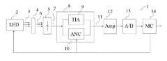
- FIG. 1shows a schematic block diagram of an embodiment of a proposed PPG signal measurement apparatus.
- FIG. 2is a diagram illustration the ambient light cancellation: 1- PPG pulse signal with ambient light noise, 2- clear pulse signal after the ambient light noise cancellation.
- FIG. 3is the electrical diagram of the front-end of the PPG sensor according to an embodiment of the present invention.
- Disclosed aspectsmay be used in photoplethysmographic measurement apparatus to improve PPG pulse-signal quality by cancellation of ambient optical and electrical noises.
- the measurement instrumentwill be described in terms of a PPG optical sensor which noninvasively measures various blood values, such as heart rate, blood oxygen saturation, blood pressure, etc.
- the PPG signal measurement apparatus 1comprises a light source 2 (e.g. an LED) for emitting light pulses 3 into tissue 4 of a living being, in particular a person.
- the light source 2may, e.g., be mounted on a finger, ear clip, or a watch worn by the living being.
- the apparatus 1further includes a light sensor 5 (e.g. a photodiode) for receiving light 6 from the tissue 4 and generating a sensor signal 7 (e.g. a photodiode current).
- a combination unit 8receives the sensor signal 7 .
- the combination unit 8cancels ambient noise in the sensor signal 7 and produces a current-to-voltage amplified signal from the sensor signal 7 .
- the combined unit 8includes a transimpedance amplifier (TIA) 9 and an ambient noise cancelation unit 10 .
- the combined unit 8receives the sensor signal 7 and transforms the signal into a clear or clearer amplified sensor signal 11 (e.g. for amplifying the photodiode current into a voltage signal without or with reduced ambient noises).
- the processed signal 11may be then be received by additional signal processing units, such as an additional amplifier 12 , analog-digital converter 13 and microcontroller 14 .
- additional signal processing unitssuch as an additional amplifier 12 , analog-digital converter 13 and microcontroller 14 .
- the microcontroller 14may be configured to control the light source 2 and the combination unit 8 , e.g. the ambient light cancelation unit 10 and the transimpedance amplifier 9 ( FIG. 3 ). In certain embodiments, such that a first switch 30 in a front end portion of the combination unit 8 may be only switched on during time periods while the light source 2 is switched off and that a second switch 40 in the front end of the combination unit 8 is only switched on during time periods while the light source 2 is switched on. Details regarding the front end of the combination unit 8 will be discussed below in reference to FIG. 3 .
- FIG. 2there is a graph of conventional signal (or pulse waveform) with ambient light noise measured by a photodetector as a function of time.
- the pulse waveformis produced by a pulse PPG optical sensor as a result of light signal radiated by LED with corresponding wavelength and ambient optical and/or electrical noises.
- the waveform 21represents a PPG pulse signal with ambient light noise.
- the waveform 22represents a PPG pulse signal after the ambient light noise cancellation or reduction (e.g., a clear signal).
- FIG. 2is a time diagram of a PPG sensor (sensor 5 ) response to the ambient light cancellation process.
- FIG. 3is an electrical diagram of the front-end of the PPG sensor (sensor 5 ) implementing one embodiment of the ambient noise cancellation process.
- the diagram suggested disclosed aspectsallow cancellation the ambient noises and obtaining clear PPG pulse signal (graph 2 , FIG. 2 ).
- the principleis that during the time period t 1 (before LED is turned on) the switch 30 is turned on. During this time period the capacitor C 2 is charged. When the LED is turned on, the switch 30 is turned off and the switch 40 is turned on, so the capacitor C 2 is discharged. The capacitor C 2 acts as a voltage drop proportional to the light when no LEDs are turned on.
- a clear pulse signal(graph 21 , FIG. 2 ) from LED light during pulse time period t 2 is measured with ambient noise cancellation. So there is no necessity to measure ambient light level for further subtraction, and the signal value is always in the amplifier range.
- a dark signal, or ambient light level detection processuses a very short time period t 1 ( ⁇ 10 us) just before each of the light emitter wavelengths (red and infrared in one embodiment) to compensate for a variation in ambient light during the detected signal.
- an improved photoplethysmographic measurement systemin which a portion of a time division multiplexed (TDM) signal represents an ambient light level, and other TDM signal portions represent detected levels of two or more centered wavelengths of transmitted light.
- the ambient light portions of the signalare effectively canceled from detected light portion before they are sent as inputs of an instrumentation amplifier(s) so as to produce a continuous output voltage that is proportional to a difference in signal levels between the ambient and detected light portions of a TDM signal.
- Such an approachprovides for ambient light level subtraction with reduced noise and allows to use all diapason of current-voltage transimpedance amplifier thus increasing significantly SNR and allowing only the useful optical signal to be received by the optical measurement system.
- Such apparatus and methodallow increase and enhance the performance of the sensor.
Landscapes
- Health & Medical Sciences (AREA)
- Life Sciences & Earth Sciences (AREA)
- Engineering & Computer Science (AREA)
- Physics & Mathematics (AREA)
- Molecular Biology (AREA)
- General Health & Medical Sciences (AREA)
- Biophysics (AREA)
- Pathology (AREA)
- Veterinary Medicine (AREA)
- Biomedical Technology (AREA)
- Heart & Thoracic Surgery (AREA)
- Medical Informatics (AREA)
- Public Health (AREA)
- Surgery (AREA)
- Animal Behavior & Ethology (AREA)
- Cardiology (AREA)
- Physiology (AREA)
- Signal Processing (AREA)
- Artificial Intelligence (AREA)
- Computer Vision & Pattern Recognition (AREA)
- Psychiatry (AREA)
- Spectroscopy & Molecular Physics (AREA)
- Optics & Photonics (AREA)
- Vascular Medicine (AREA)
- Power Engineering (AREA)
- Measuring Pulse, Heart Rate, Blood Pressure Or Blood Flow (AREA)
Abstract
Description
Claims (6)
Priority Applications (2)
| Application Number | Priority Date | Filing Date | Title |
|---|---|---|---|
| US14/674,499US9936885B1 (en) | 2014-03-31 | 2015-03-31 | Apparatus for ambient noise cancellation in PPG sensors |
| US15/365,242US20190142286A1 (en) | 2014-03-31 | 2016-11-30 | Photoplethysmographic wearable blood pressure monitoring system and methods |
Applications Claiming Priority (2)
| Application Number | Priority Date | Filing Date | Title |
|---|---|---|---|
| US201461972905P | 2014-03-31 | 2014-03-31 | |
| US14/674,499US9936885B1 (en) | 2014-03-31 | 2015-03-31 | Apparatus for ambient noise cancellation in PPG sensors |
Related Parent Applications (1)
| Application Number | Title | Priority Date | Filing Date |
|---|---|---|---|
| US14/675,639Continuation-In-PartUS10117586B1 (en) | 2014-03-31 | 2015-03-31 | Continuous non-invasive wearable blood pressure monitoring system |
Related Child Applications (1)
| Application Number | Title | Priority Date | Filing Date |
|---|---|---|---|
| US15/365,242Continuation-In-PartUS20190142286A1 (en) | 2014-03-31 | 2016-11-30 | Photoplethysmographic wearable blood pressure monitoring system and methods |
Publications (1)
| Publication Number | Publication Date |
|---|---|
| US9936885B1true US9936885B1 (en) | 2018-04-10 |
Family
ID=61801563
Family Applications (1)
| Application Number | Title | Priority Date | Filing Date |
|---|---|---|---|
| US14/674,499Active2036-05-10US9936885B1 (en) | 2014-03-31 | 2015-03-31 | Apparatus for ambient noise cancellation in PPG sensors |
Country Status (1)
| Country | Link |
|---|---|
| US (1) | US9936885B1 (en) |
Citations (29)
| Publication number | Priority date | Publication date | Assignee | Title |
|---|---|---|---|---|
| US4781195A (en) | 1987-12-02 | 1988-11-01 | The Boc Group, Inc. | Blood monitoring apparatus and methods with amplifier input dark current correction |
| US5713355A (en) | 1992-10-23 | 1998-02-03 | Nellcor Puritan Bennett Incorporated | Method and apparatus for reducing ambient noise effects in electronic monitoring instruments |
| US5846190A (en) | 1995-10-10 | 1998-12-08 | Hewlett-Packard Company | Method of and apparatus for recognizing falsified pulse oximetry measurements |
| US5853372A (en)* | 1995-08-14 | 1998-12-29 | Advanced Body Metrics Corporation | Near infra-red signal processing system |
| US5954644A (en) | 1997-03-24 | 1999-09-21 | Ohmeda Inc. | Method for ambient light subtraction in a photoplethysmographic measurement instrument |
| WO2001043624A2 (en) | 1999-12-17 | 2001-06-21 | Datex-Ohmeda, Inc. | Method for de-weighting motion-contaminated data in photoplethysmographic analyte measurements |
| US6385471B1 (en) | 1991-09-03 | 2002-05-07 | Datex-Ohmeda, Inc. | System for pulse oximetry SpO2 determination |
| US7384398B2 (en) | 2000-05-05 | 2008-06-10 | Universite De Rennes | Device and method for detecting abnormal situations |
| WO2008109185A2 (en) | 2007-03-06 | 2008-09-12 | Kensey Kenneth R | A noninvasive method to determine characteristics of the heart |
| US7616110B2 (en) | 2005-03-11 | 2009-11-10 | Aframe Digital, Inc. | Mobile wireless customizable health and condition monitor |
| US20100016738A1 (en) | 2008-07-15 | 2010-01-21 | Nellcor Puritan Bennett Ireland | Systems and methods for pulse processing |
| US7740591B1 (en) | 2003-12-01 | 2010-06-22 | Ric Investments, Llc | Apparatus and method for monitoring pressure related changes in the extra-thoracic arterial circulatory system |
| US7827011B2 (en) | 2005-05-03 | 2010-11-02 | Aware, Inc. | Method and system for real-time signal classification |
| US8313439B2 (en) | 2009-03-20 | 2012-11-20 | Massachusetts Institute Of Technology | Calibration of pulse transit time measurements to arterial blood pressure using external arterial pressure applied along the pulse transit path |
| US8378811B2 (en) | 2005-03-11 | 2013-02-19 | Aframe Digital, Inc. | Mobile wireless customizable health and condition monitor |
| US8618930B2 (en) | 2005-03-11 | 2013-12-31 | Aframe Digital, Inc. | Mobile wireless customizable health and condition monitor |
| US20140142460A1 (en) | 2011-04-29 | 2014-05-22 | Koninklijke Philips N.V. | Method for detecting potential falls and a fall detector |
| US8866606B1 (en) | 2013-07-16 | 2014-10-21 | Rockwilli RMR LLC | Systems and methods for automated personal emergency responses |
| US9135699B2 (en) | 2012-03-15 | 2015-09-15 | Siemens Aktiengesellschaft | Method and system for hemodynamic assessment of aortic coarctation from medical image data |
| US20160038061A1 (en) | 2013-03-22 | 2016-02-11 | Koninklijke Philips N.V. | Method for detecting falls and a fall detector |
| US20160038044A1 (en) | 2014-08-11 | 2016-02-11 | Tata Consultancy Services Limited | Measuring blood pressure |
| US20160174913A1 (en) | 2014-12-23 | 2016-06-23 | Intel Corporation | Device for health monitoring and response |
| US9396645B2 (en) | 2013-07-16 | 2016-07-19 | Rockwilli RMR LLC | Systems and methods for automated personal emergency responses |
| US20160213314A1 (en) | 2013-09-29 | 2016-07-28 | Medasense Biometrics Ltd. | Device and method for determining spinal cord stimulation efficacy |
| US9526421B2 (en) | 2005-03-11 | 2016-12-27 | Nrv-Wellness, Llc | Mobile wireless customizable health and condition monitor |
| US9547977B2 (en) | 2013-07-16 | 2017-01-17 | Rockwilli RMR LLC | Systems and methods for automated personal emergency responses |
| US9640057B1 (en) | 2015-11-23 | 2017-05-02 | MedHab, LLC | Personal fall detection system and method |
| US9704154B2 (en) | 2002-10-01 | 2017-07-11 | World Award Academy, World Award Foundation, Amobilepay, Inc. | Wearable personal digital device for facilitating mobile device payments and personal use |
| US9773397B2 (en) | 2013-08-26 | 2017-09-26 | Koninklijke Philips N.V. | Method for detecting falls and a fall detection system |
- 2015
- 2015-03-31USUS14/674,499patent/US9936885B1/enactiveActive
Patent Citations (33)
| Publication number | Priority date | Publication date | Assignee | Title |
|---|---|---|---|---|
| US4781195A (en) | 1987-12-02 | 1988-11-01 | The Boc Group, Inc. | Blood monitoring apparatus and methods with amplifier input dark current correction |
| US6385471B1 (en) | 1991-09-03 | 2002-05-07 | Datex-Ohmeda, Inc. | System for pulse oximetry SpO2 determination |
| US5713355A (en) | 1992-10-23 | 1998-02-03 | Nellcor Puritan Bennett Incorporated | Method and apparatus for reducing ambient noise effects in electronic monitoring instruments |
| US5885213A (en) | 1992-10-23 | 1999-03-23 | Nellcor Puritan Bennett Incorporated | Method and apparatus for reducing ambient noise effects in electronic monitoring instruments |
| US5853372A (en)* | 1995-08-14 | 1998-12-29 | Advanced Body Metrics Corporation | Near infra-red signal processing system |
| US5846190A (en) | 1995-10-10 | 1998-12-08 | Hewlett-Packard Company | Method of and apparatus for recognizing falsified pulse oximetry measurements |
| US5954644A (en) | 1997-03-24 | 1999-09-21 | Ohmeda Inc. | Method for ambient light subtraction in a photoplethysmographic measurement instrument |
| WO2001043624A2 (en) | 1999-12-17 | 2001-06-21 | Datex-Ohmeda, Inc. | Method for de-weighting motion-contaminated data in photoplethysmographic analyte measurements |
| US7384398B2 (en) | 2000-05-05 | 2008-06-10 | Universite De Rennes | Device and method for detecting abnormal situations |
| US9704154B2 (en) | 2002-10-01 | 2017-07-11 | World Award Academy, World Award Foundation, Amobilepay, Inc. | Wearable personal digital device for facilitating mobile device payments and personal use |
| US7740591B1 (en) | 2003-12-01 | 2010-06-22 | Ric Investments, Llc | Apparatus and method for monitoring pressure related changes in the extra-thoracic arterial circulatory system |
| US8378811B2 (en) | 2005-03-11 | 2013-02-19 | Aframe Digital, Inc. | Mobile wireless customizable health and condition monitor |
| US9526421B2 (en) | 2005-03-11 | 2016-12-27 | Nrv-Wellness, Llc | Mobile wireless customizable health and condition monitor |
| US20170172463A1 (en) | 2005-03-11 | 2017-06-22 | Nrv-Wellness, Llc | Mobile wireless customizable health and condition monitor |
| US8618930B2 (en) | 2005-03-11 | 2013-12-31 | Aframe Digital, Inc. | Mobile wireless customizable health and condition monitor |
| US7616110B2 (en) | 2005-03-11 | 2009-11-10 | Aframe Digital, Inc. | Mobile wireless customizable health and condition monitor |
| US8036842B2 (en) | 2005-05-03 | 2011-10-11 | Aware, Inc. | Method and system for real-time signal classification |
| US7827011B2 (en) | 2005-05-03 | 2010-11-02 | Aware, Inc. | Method and system for real-time signal classification |
| WO2008109185A2 (en) | 2007-03-06 | 2008-09-12 | Kensey Kenneth R | A noninvasive method to determine characteristics of the heart |
| US20100016738A1 (en) | 2008-07-15 | 2010-01-21 | Nellcor Puritan Bennett Ireland | Systems and methods for pulse processing |
| US8313439B2 (en) | 2009-03-20 | 2012-11-20 | Massachusetts Institute Of Technology | Calibration of pulse transit time measurements to arterial blood pressure using external arterial pressure applied along the pulse transit path |
| US9489815B2 (en) | 2011-04-29 | 2016-11-08 | Koninklijke Philips N.V. | Apparatus for use in a fall detector or fall detection system, and a method of operating the same |
| US20140142460A1 (en) | 2011-04-29 | 2014-05-22 | Koninklijke Philips N.V. | Method for detecting potential falls and a fall detector |
| US9135699B2 (en) | 2012-03-15 | 2015-09-15 | Siemens Aktiengesellschaft | Method and system for hemodynamic assessment of aortic coarctation from medical image data |
| US20160038061A1 (en) | 2013-03-22 | 2016-02-11 | Koninklijke Philips N.V. | Method for detecting falls and a fall detector |
| US9396645B2 (en) | 2013-07-16 | 2016-07-19 | Rockwilli RMR LLC | Systems and methods for automated personal emergency responses |
| US9547977B2 (en) | 2013-07-16 | 2017-01-17 | Rockwilli RMR LLC | Systems and methods for automated personal emergency responses |
| US8866606B1 (en) | 2013-07-16 | 2014-10-21 | Rockwilli RMR LLC | Systems and methods for automated personal emergency responses |
| US9773397B2 (en) | 2013-08-26 | 2017-09-26 | Koninklijke Philips N.V. | Method for detecting falls and a fall detection system |
| US20160213314A1 (en) | 2013-09-29 | 2016-07-28 | Medasense Biometrics Ltd. | Device and method for determining spinal cord stimulation efficacy |
| US20160038044A1 (en) | 2014-08-11 | 2016-02-11 | Tata Consultancy Services Limited | Measuring blood pressure |
| US20160174913A1 (en) | 2014-12-23 | 2016-06-23 | Intel Corporation | Device for health monitoring and response |
| US9640057B1 (en) | 2015-11-23 | 2017-05-02 | MedHab, LLC | Personal fall detection system and method |
Non-Patent Citations (6)
| Title |
|---|
| Addison et al., "Developing an algorithm for pulse oximetry derived respiratory rate (RRoxi): a healthy volunteer study", J. Clin. Monit Comput, 2012, vol. 26, pp. 45-51. |
| Burns, "Senso Track Monitors Biometric Health Through Your Ear", downloaded http://www.slashgear.com/sensotrack-monitors-biometric-health-through-your-ear-22351940, Sep. 25, 2016, 8 pages. |
| George et al., "Respiration Rate Measurement From PPG Signal Using Smart Fusion Technique", International Conference on Engineering Trends and Science & Humanities, 2015, 5 pages. |
| Image of Sensotrack, downloaded Sep. 25, 2016, 1 page. |
| Lazaro et al., "Deriving respiration from photoplethysmographic pulse width", Med. Bio. Eng. Comput., 2013, vol. 51, pp. 233-242. |
| Meredith et al., "Photoplethysmographic derivation of respiratory rate: a review of relevant physiology", Journal of Medical Engineering & Technology, 2012, pp. 60-66. |
Similar Documents
| Publication | Publication Date | Title |
|---|---|---|
| Patterson et al. | A flexible, low noise reflective PPG sensor platform for ear-worn heart rate monitoring | |
| US10433738B2 (en) | Method and apparatus for optical sensing of tissue variation at increased accuracy | |
| US7190985B2 (en) | Oximeter ambient light cancellation | |
| EP3016582B1 (en) | Photoplethysmography sensor apparatus and method | |
| Patterson et al. | Ratiometric artifact reduction in low power reflective photoplethysmography | |
| EP1237467A1 (en) | Pulse oximeter with improved dc and low frequency rejection | |
| US20050049468A1 (en) | Increasing the performance of an optical pulsoximeter | |
| EP3406194B1 (en) | Circuit arrangement for an optical monitoring system and method for optical monitoring | |
| MXPA06010318A (en) | Pulse oximetry motion artifact rejection using near infrared absorption by water. | |
| EP3135196B1 (en) | Circuit arrangement for an optical monitoring system and method for optical monitoring | |
| US8847578B2 (en) | Ambient noise cancellation in pulsed input system | |
| EP3277172B1 (en) | Optical analysis system and method | |
| US9936885B1 (en) | Apparatus for ambient noise cancellation in PPG sensors | |
| CN113965953B (en) | Control method of wearable device and wearable device | |
| CN114052696B (en) | PPG signal detection method, component and wearable device | |
| WO2014013813A1 (en) | Tissue sensor | |
| US20120136257A1 (en) | SNR Through Ambient Light Cancellation | |
| US8521246B2 (en) | Cable cross talk suppression | |
| CN119073941A (en) | Wearable device and heart rate measurement method |
Legal Events
| Date | Code | Title | Description |
|---|---|---|---|
| AS | Assignment | Owner name:SENSOGRAM TECHNOLOGIES, INC., TEXAS Free format text:ASSIGNMENT OF ASSIGNORS INTEREST;ASSIGNORS:MOURADIAN, VAHRAM;HOVHANNISYAN, LEVON;POGHOSYAN, ARMEN;REEL/FRAME:035542/0255 Effective date:20150423 | |
| STCF | Information on status: patent grant | Free format text:PATENTED CASE | |
| AS | Assignment | Owner name:LARIUS LTD., TEXAS Free format text:ASSIGNMENT OF ASSIGNORS INTEREST;ASSIGNOR:SENSOGRAM TECHNOLOGIES, INC.;REEL/FRAME:054224/0042 Effective date:20200227 | |
| AS | Assignment | Owner name:LARIUS LTD., TEXAS Free format text:SECURITY INTEREST;ASSIGNOR:SENSOGRAM TECHNOLOGIES, INC.;REEL/FRAME:054303/0770 Effective date:20200227 | |
| FEPP | Fee payment procedure | Free format text:MAINTENANCE FEE REMINDER MAILED (ORIGINAL EVENT CODE: REM.); ENTITY STATUS OF PATENT OWNER: SMALL ENTITY | |
| AS | Assignment | Owner name:LARIUS LTD, TEXAS Free format text:ASSIGNMENT OF ASSIGNORS INTEREST;ASSIGNOR:SENSOGRAM TECHNOLOGIES, INC.;REEL/FRAME:059246/0438 Effective date:20220311 | |
| FEPP | Fee payment procedure | Free format text:SURCHARGE FOR LATE PAYMENT, SMALL ENTITY (ORIGINAL EVENT CODE: M2554); ENTITY STATUS OF PATENT OWNER: SMALL ENTITY | |
| MAFP | Maintenance fee payment | Free format text:PAYMENT OF MAINTENANCE FEE, 4TH YR, SMALL ENTITY (ORIGINAL EVENT CODE: M2551); ENTITY STATUS OF PATENT OWNER: SMALL ENTITY Year of fee payment:4 | |
| AS | Assignment | Owner name:KEHAAI, INC., CALIFORNIA Free format text:ASSIGNMENT OF ASSIGNORS INTEREST;ASSIGNOR:LARIUS LTD.;REEL/FRAME:064513/0884 Effective date:20230706 |