US9935850B1 - Systems and methods for implementing an on-demand computing network environment - Google Patents
Systems and methods for implementing an on-demand computing network environmentDownload PDFInfo
- Publication number
- US9935850B1 US9935850B1US14/937,978US201514937978AUS9935850B1US 9935850 B1US9935850 B1US 9935850B1US 201514937978 AUS201514937978 AUS 201514937978AUS 9935850 B1US9935850 B1US 9935850B1
- Authority
- US
- United States
- Prior art keywords
- rim
- network
- resources
- rim device
- demand computing
- Prior art date
- Legal status (The legal status is an assumption and is not a legal conclusion. Google has not performed a legal analysis and makes no representation as to the accuracy of the status listed.)
- Active, expires
Links
- 238000000034methodMethods0.000titleclaimsabstractdescription31
- 238000004891communicationMethods0.000claimsdescription27
- 230000001413cellular effectEffects0.000claimsdescription23
- 230000005540biological transmissionEffects0.000claimsdescription4
- 238000012545processingMethods0.000claimsdescription4
- 238000010586diagramMethods0.000description32
- 230000010267cellular communicationEffects0.000description5
- 241000238366CephalopodaSpecies0.000description2
- 230000008859changeEffects0.000description2
- 238000012544monitoring processMethods0.000description2
- 238000013459approachMethods0.000description1
- 230000000903blocking effectEffects0.000description1
- 230000000694effectsEffects0.000description1
- 230000000977initiatory effectEffects0.000description1
- 238000003780insertionMethods0.000description1
- 230000037431insertionEffects0.000description1
- 230000006855networkingEffects0.000description1
- 230000008520organizationEffects0.000description1
- 230000002265preventionEffects0.000description1
- 230000007704transitionEffects0.000description1
Images


Classifications
- H—ELECTRICITY
- H04—ELECTRIC COMMUNICATION TECHNIQUE
- H04L—TRANSMISSION OF DIGITAL INFORMATION, e.g. TELEGRAPHIC COMMUNICATION
- H04L41/00—Arrangements for maintenance, administration or management of data switching networks, e.g. of packet switching networks
- H04L41/50—Network service management, e.g. ensuring proper service fulfilment according to agreements
- H04L41/5041—Network service management, e.g. ensuring proper service fulfilment according to agreements characterised by the time relationship between creation and deployment of a service
- H04L41/5051—Service on demand, e.g. definition and deployment of services in real time
- H—ELECTRICITY
- H04—ELECTRIC COMMUNICATION TECHNIQUE
- H04L—TRANSMISSION OF DIGITAL INFORMATION, e.g. TELEGRAPHIC COMMUNICATION
- H04L12/00—Data switching networks
- H04L12/28—Data switching networks characterised by path configuration, e.g. LAN [Local Area Networks] or WAN [Wide Area Networks]
- H04L12/46—Interconnection of networks
- H04L12/4641—Virtual LANs, VLANs, e.g. virtual private networks [VPN]
- H—ELECTRICITY
- H04—ELECTRIC COMMUNICATION TECHNIQUE
- H04L—TRANSMISSION OF DIGITAL INFORMATION, e.g. TELEGRAPHIC COMMUNICATION
- H04L41/00—Arrangements for maintenance, administration or management of data switching networks, e.g. of packet switching networks
- H04L41/12—Discovery or management of network topologies
- H—ELECTRICITY
- H04—ELECTRIC COMMUNICATION TECHNIQUE
- H04L—TRANSMISSION OF DIGITAL INFORMATION, e.g. TELEGRAPHIC COMMUNICATION
- H04L41/00—Arrangements for maintenance, administration or management of data switching networks, e.g. of packet switching networks
- H04L41/22—Arrangements for maintenance, administration or management of data switching networks, e.g. of packet switching networks comprising specially adapted graphical user interfaces [GUI]
- H—ELECTRICITY
- H04—ELECTRIC COMMUNICATION TECHNIQUE
- H04L—TRANSMISSION OF DIGITAL INFORMATION, e.g. TELEGRAPHIC COMMUNICATION
- H04L63/00—Network architectures or network communication protocols for network security
- H04L63/04—Network architectures or network communication protocols for network security for providing a confidential data exchange among entities communicating through data packet networks
- H04L63/0428—Network architectures or network communication protocols for network security for providing a confidential data exchange among entities communicating through data packet networks wherein the data content is protected, e.g. by encrypting or encapsulating the payload
- H—ELECTRICITY
- H04—ELECTRIC COMMUNICATION TECHNIQUE
- H04L—TRANSMISSION OF DIGITAL INFORMATION, e.g. TELEGRAPHIC COMMUNICATION
- H04L67/00—Network arrangements or protocols for supporting network services or applications
- H04L67/01—Protocols
- H04L67/10—Protocols in which an application is distributed across nodes in the network
- H04L67/2814—
- H—ELECTRICITY
- H04—ELECTRIC COMMUNICATION TECHNIQUE
- H04L—TRANSMISSION OF DIGITAL INFORMATION, e.g. TELEGRAPHIC COMMUNICATION
- H04L67/00—Network arrangements or protocols for supporting network services or applications
- H04L67/50—Network services
- H04L67/56—Provisioning of proxy services
- H04L67/563—Data redirection of data network streams
- H—ELECTRICITY
- H04—ELECTRIC COMMUNICATION TECHNIQUE
- H04W—WIRELESS COMMUNICATION NETWORKS
- H04W88/00—Devices specially adapted for wireless communication networks, e.g. terminals, base stations or access point devices
- H04W88/02—Terminal devices
- H—ELECTRICITY
- H04—ELECTRIC COMMUNICATION TECHNIQUE
- H04L—TRANSMISSION OF DIGITAL INFORMATION, e.g. TELEGRAPHIC COMMUNICATION
- H04L41/00—Arrangements for maintenance, administration or management of data switching networks, e.g. of packet switching networks
- H04L41/08—Configuration management of networks or network elements
- H04L41/0803—Configuration setting
- H04L41/0806—Configuration setting for initial configuration or provisioning, e.g. plug-and-play
Definitions
- This disclosureis related generally to computer networking and more particularly to implementation of an on-demand computing network environment.
- a computing networktypically includes a plurality of computing devices that are connected with one another, either physically or wirelessly, such that those computing devices can communicate with one another.
- a networkis typically constructed by acquiring, either physically or via contractual agreement, the resources necessary to implement a desired framework. Typically, such components are acquired on a component by component basis.
- Systems and methodsare provided for a computer-implemented method of implementing an on-demand computing network environment.
- a network specificationis received from a user.
- Resources from one or more resource providersare provisioned.
- the on-demand computing networkis configured, where configuring comprises assigning a first provisioned resource as a hub device and assigning one or more second provisioned resources as rim devices, where rim devices are configured to communicate with one another only via the hub device.
- a computer-implemented system for implementing an on-demand computing network environmentincludes a provisioned resource data store configured to store records associated with resources provisioned from one or more resource providers, where records in the provisioned resources data store include an identification of a particular resource and a particular on-demand computing network to which the particular resource has been assigned.
- a network implementation engineis configured to receive a network specification from a user, assign a first provisioned resource as a hub device to the particular on-demand computing network and to update the provisioned resource data store, and assign one or more second provisioned resources as rim devices to the particular on-demand computing network and to update the provisioned resource data store, wherein rim devices are configured to communicate with one another only via the hub device.
- FIG. 1is a block diagram depicting a computer-implemented environment for implementing an on-demand computing network.
- FIG. 2is a diagram depicting a network implementation engine providing on-demand network setup and re-configuration operations.
- FIG. 3is a diagram depicting an on-demand computing network in operation.
- FIG. 4is a diagram depicting an example user interface for selecting entry and exit points for an on-demand computing network.
- FIG. 5is a diagram depicting an example configuration of a spoke from a hub device to a rim device.
- FIG. 6is a diagram depicting an example on-demand computing network environment.
- FIG. 7is a diagram depicting an on-demand computing network configured for cellular communications.
- FIG. 8is a diagram depicting another on-demand computing network environment.
- FIG. 9is a diagram depicting an example on-demand network topology.
- FIG. 10is a diagram depicting a first example use case for a system for implementing an on-demand computing network environment.
- FIG. 11is a diagram depicting a second example use case for a system for implementing an on-demand computing network environment.
- FIG. 12is a diagram depicting a third example use case for a system for implementing an on-demand computing network environment.
- FIG. 13is a diagram depicting a fourth example use case for a system for implementing an on-demand computing network environment.
- FIG. 14is a user interface for selecting a project with which to interact.
- FIG. 15is a diagram depicting provisioned computing resources within the on-demand computing network.
- FIG. 16is a diagram depicting resources available in a pool of acquired resources.
- FIG. 17is a diagram depicting resources deployed into an on-demand computing network, including physical locations of those deployed resources.
- FIG. 1is a block diagram depicting a computer-implemented environment for implementing an on-demand computing network.
- the environment 100 of FIG. 1enables a user 102 to specify and acquire a network designed to the user's specification in real time.
- a user 102transmits a network specification 104 that represents a desired network topology to a network implementation engine 106 .
- the network implementation engine 106interacts with a pool of acquired resources 108 to build a network 110 that corresponds with the desired network identified by the user in the network specification 104 .
- the network implementation engine 106is configured to examine the network specification 104 and provision resources necessary to implement the user's desired network configuration.
- the pool of resources 108may contain a variety of resources of different types, which may also come from different providers.
- a first resource 112may be a cloud processing resource (“third party compute service provider processing resource”) acquired from a first provider who provides servers with processing capabilities available for accessing.
- a second resource 114may be mail server or file server resource provided by the same provider or from a different provider.
- a third resource 116may be a cellular communication resource from a third provider, where that cellular communication resource enables acquisition of voice or video conference data from a party via a device of that party's data communication capabilities.
- Other resourcescan include proxy server resources for forwarding traffic, media servers for providing media (e.g., video, audio, image), as well as others.
- the network implementation engine 106interacts with the pool of acquired resources 108 to provision resources needed to create the desired on-demand computing network 110 .
- the network implementation engine 106assigns the provisioned resources to the network and configures the network topology.
- the on-demand network 110is configured as a wheel network having a hub device 118 (e.g., a server) and one or more rim devices 120 , 122 , 124 , 126 that can take the form of servers of different types or other computing components.
- the rim devicescommunicate with one another, in one embodiment, only through the hub device 118 , where communications between the hub device 118 and the rim devices can be via secure connections, such as a VPN connection.
- rim devicese.g., rim devices 120 , 124 , 126
- Rim device 124is configured to provide a secure link from the user 102 to the hub device 118 and other resources of the network 110 , such as via a VPN connection.
- Rim devices that are not identified as exit pointsare, in one embodiment, not permitted to communicate outside the network 110 .
- Such rim devicese.g., rim device 122
- connection between the hub device 118 and rim device 120includes two joints connected by a joint relay 128 , which can be implemented using a proxy server configured to forward traffic.
- a proxy serverconfigured to forward traffic. Utilization of a plurality of joints along a spoke from the hub device 118 to a rim device 120 provides an additional degree of anonymity, where rim device 120 can function without knowing a physical address of the hub device 118 , knowing only to forward data to joint relay 128 , and where hub device 118 can function without knowledge of a physical address of the rim device 120 .
- the network implementation engine 106configures the hub device 118 to communicate to rim device 120 via joint relay 128 without providing the physical address of rim device 120 to the hub device 118 .
- the network implementation engine 106similarly configures rim device 120 without informing rim device 120 of a physical address of the hub device 118 .
- FIG. 2is a diagram depicting a network implementation engine providing on-demand network setup and re-configuration operations.
- the network implementation engine 202builds the on-demand computing network 204 according to a user provided network specification.
- the network implementation engine 202is also configured to add resources from a pool of acquired resources 206 to the network 204 and to de-provision resources when those resources are no longer needed. In one embodiment, only the network implementation engine 202 is permitted to add resources to or remove resources from the on-demand computing network 204 .
- the network implementation engine 202accesses the resource from the pool of acquired resources 206 if the needed resource is available.
- the pool of acquired resources 206may include a number of accounts with different third party computing service providers, online e-mail accounts, and file sharing accounts that the network implementation engine 202 can access and assign to the on-demand computing network to generate a desired user network topology. If a desired resource is not in the pool of acquired resources 206 , then the network implementation engine 202 can acquire the desired resource or direct another entity to acquire the desire resource, with the resource then being assigned to the on-demand computing network 204 .
- the network implementation engine 202assigns the hub device 208 , the rim devices 210 , and communication links among them (e.g., identifying addresses with which the hub device 208 and rim devices 210 are configured to communicate with in the network 2014 ) to the network 204 .
- the network implementation engine 202takes a hands off approach, where the network implementation engine 202 does not monitor or communicate with the network 204 while the network is in operation.
- the network implementation engine 202receives no data about operations performed using the network 204 beyond knowledge of resources assigned to the network (e.g., as stored in records of a configuration data store).
- the network implementation engine 202Upon receipt of a user request to add resources to the network 204 or remove resources therefrom, the network implementation engine 202 again interacts with the network 204 to implement the newly desired topology.
- de-provisioning of resources by the network implementation engine 202is performed without direct communication with the network 204 .
- the network implementation engine 202communicates with providers of the resources, indicating to those providers that the resource is to be de-provisioned.
- the de-provisioned resourcecan then be recycled for use with another on-demand computing network, such as a network associated with a different user.
- a providerupon receipt of a de-provisioning request for a resource, a provider resets the resource (e.g., deletes stored data, such as e-mails or files) to an initial state so that it is ready for reuse. In this manner, the network implementation engine 202 acquires no further data associated with operation of the network 204 .
- FIG. 3is a diagram depicting an on-demand computing network in operation. Once the on-demand computing network 302 is implemented, the network 302 functions without communication with the network configuration engine.
- the on-demand computing network 302includes a hub device 304 that communicates with a plurality of rim devices 306 , 308 , 310 , 312 .
- Rim device 312provides a portal for a user 314 to communicate with resources within the network 302 and computing devices external to the network 302 through the network, as described further herein.
- Rim devices 308 , 310are designated as exit points through which the network 302 can communicate traffic out of the network 302 .
- Rim device 306provides a network service (e.g., a file server, a mail server) accessible to a user 314 , other rim devices 308 , 310 , 312 within the network, and computing devices external to the network via rim devices (e.g., rim device 310 ) that are configured to receive traffic from outside of the network 302 .
- a network servicee.g., a file server, a mail server
- routing of traffic through rim devices 308 , 310 designated as exit pointsis user configurable during network 302 operation.
- the hub device 304includes a service broker operating thereon.
- the service brokeris configured to enable configuration changes to be made to resources currently assigned to the network 302 .
- the service brokeris tasked with changing routing of traffic to and from the network 302 via rim devices 308 , 310 designated for communications outside of the network, on command.
- the service brokerprovides a user interface to a user 314 for designation of traffic routing.
- the user interfaceincludes a listing of one or more types of traffic (e.g., e-mail, Http requests) that can be transmitted from the network 302 via one of the exit point rim devices 308 , 310 .
- the user interfacefurther includes a listing of available exit point rim devices 308 , 310 .
- the user 314selects a traffic type and an exit point 308 , 310 with which to associate that type of traffic. That type of traffic is then directed out of the network 302 through that selected exit point 308 , 310 . Transitions between exit points for different types of traffic can be performed on user command without requiring a user to reconnect (e.g., via a VPN connection) to the network 302 .
- Such operationenables a disguising of a source of data to a party receiving traffic from the network. For example, if rim device 308 is positioned in Asia, while rim device 310 is positioned in South America, user selection of rim device 308 for Http traffic instead of rim device 310 will change an apparent source of the next Http request to be Asia instead of South America.
- Such operationscan circumvent certain computing devices external to the network 302 from blocking communications with the network 302 , where those external computing devices are configured to restrict communications based on the geographic location of incoming communications.
- FIG. 4is a diagram depicting an example user interface for selecting entry and exit points for an on-demand computing network.
- a first portion 402 of the user interfaceidentifies rim devices that configured to operate as entry points, where data can enter into the on-demand computing network.
- a second portion 404identifies rim devices that are configured to operate as exit points, where data can be transmitted from the on-demand computing network.
- trafficcan be routed accordingly. For example, by selecting a first rim server in portion 404 , traffic can be made to appear to be coming from San Diego. By changing that selection to a third entry in portion 404 , that same traffic can be made to appear as originating from Singapore. It is noted that only logical address of the entry and exit points within the network are provided at 402 , 404 .
- FIG. 5is a diagram depicting an example configuration of a spoke from a hub device to a rim device.
- a hub device 502is configured to communicate with a rim device 504 via two joints 506 , 508 .
- the joints 506 , 508are connected via a joint relay device 510 , which can take the form of a proxy server configured to forward received traffic.
- Communications along the joints 506 , 508 via the joint relay 510are performed using an SSH protocol, which enables secure communications between the hub device 502 and the rim device 504 via a VPN connection.
- communications between the hub device 502 and the rim device 504can be performed without either device 502 , 504 knowing a physical address of the other.
- the hub device 502need only have sufficient address information to communicate with the joint relay 510 via joint 506 for that traffic to reach rim device 504 , with rim device 504 similarly only needing sufficient data to communicate with joint relay 510 via joint 508 . Further anonymity can be achieved through insertion of additional joints and corresponding joint relays between the hub device 502 and the rim device 504 .
- FIG. 6is a diagram depicting an example on-demand computing network environment.
- a hub device 602communicates with four rim devices 604 , 606 , 608 , 610 . Connections between three of the rim devices 604 , 608 , 610 include a plurality of joints. Joint communications can be via a SSH protocol, enabling VPN connectivity between rim devices 604 , 606 , 608 , 610 and the hub device 602 .
- a first rim device 604operates as an entry point that facilitates communication between the on-demand computing network and a user 612 .
- the user 612can communicate with the network via rim device 604 to access services of the network, to configure components of the network (e.g., via a service broker operating on the hub device 602 ) and to communicate with computing devices outside of the network through the network, using exit point rim devices 608 , 610 .
- Rim device 606provides a service to the network (e.g., an image sharing service) that can be accessed by the user 612 , other rim devices 604 , 608 , 610 , or devices external to the network.
- Two rim devices 608 , 610are designated as exit points, where the user can selectively transmit data to the outside of the network, where transmission from one exit point rim server 608 instead of another exit point rim server 610 can change an apparent originating source of the data transmission.
- FIG. 7is a diagram depicting an on-demand computing network configured for cellular communications.
- a userinteracts with a network implementation engine 702 , such as via a desktop computer connection 704 or a cellular connection 706 to set up an on-demand network.
- the network implementation engine 702provisions resources to implement the desired network that includes a hub device 708 , a first rim computing device 710 designated for external data communications, a second rim device 712 designated for external cellular communications, and an third rim device 714 configured to provide a service for the network (e.g., a VOIP management service).
- Connection datacan be provided to clients, such that a particular client only receives data associated with his connection to the network.
- a desktop user 704is provided address data for communicating with the first rim device 710
- a cellular user 706is provided address data for communicating with the second rim device 712 .
- the clients 704have no knowledge of other clients' physical addresses.
- Physical addresses of network devicesare also limited, such that the first rim device 710 is unaware of a physical address of the second rim device 712 .
- the second rim device 712Upon connection of the parties a telephone conversation or video conference can occur via the network.
- the second rim device 712is configured to communicate data with a cellular user 706 via a cellular network (e.g., via a data link of the cellular network).
- the second rim device 712is configured to transmit that data within the on-demand computing network via the hub device 708 and possibly other devices internal to the network (e.g., one or more non-cellular proxy server relays) to the first rim device 710 .
- the first hub device 710is configured to relay data from the second hub device 712 (e.g., voice from cellular user 706 ) to the desktop computer user 704 for presentation (e.g., video or audio).
- the first hub device 710is also configured to receive data which is relayed to the cellular user 706 via the hub device 708 and the second rim device 712 .
- communications at 710can be with a second cellular user instead of the depicted desktop computer user 704 .
- FIG. 8is a diagram depicting another on-demand computing network environment.
- a user 802interacts with a network configuration engine 804 to implement a desired on-demand computing network and to provide a cellular user 806 with sufficient data to connect to the network in a secure manner.
- the on-demand computing networkincludes a hub device 808 .
- a first rim 810 deviceis configured for communication via a cellular network, such as via an Andriod, iOS, or Windows Mobile protocol.
- a second hub device 812is configured to communicate externally via a second data portal, such as with user 802 .
- the on-demand computing networkincludes a third hub device 814 , which connects the first and second network devices via a plurality of joints and associated joint relay servers, enabling direct communication between the first rim device 810 and the second rim device 812 without communication through the hub device 808 .
- the network implementation engineIn addition to provisioning resources (e.g., 808 , 810 , 812 ) for the on-demand computing network, the network implementation engine also provisions resources for communicating connection information to the cellular user 806 .
- a provisioned anonymous e-mail addressis used to communicate a connection address to an e-mail address of the cellular user.
- a provisioned anonymous twitter accountis used to communicate a first portion of authentication data (e.g., a password) to the cellular user 806 .
- a provisioned anonymous Facebook accountis used to communicate a second portion of the authentication data to the cellular user 806 .
- the cellular user 806can successfully establish a connection to the first rim device 810 and communication with the user 802 can begin.
- the network implementation engine 804can then de-provision the resources utilized to transmit the connection information to the cellular user 806 .
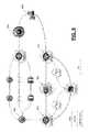
- FIG. 9is a diagram depicting an example on-demand network topology.
- a VPN hub 902communicates with a desktop server rim device 904 , a voice over IP (VOIP) server 906 , two proxy server rim devices 908 , 910 , and an exit node rim device 912 .
- the spokes to proxy server rim devices 908 , 910include joint relay devices 914 , 916 that communicate via an SSH protocol.
- a network owner 918communicates with the network via rim device 910 , while a guest user 920 communicates with the network via rim device 908 . These communications are via Https protocol links.
- the VOIP server 906enables communications to and from the network via one or more external cellular networks.
- FIG. 10is a diagram depicting a first example use case for a system for implementing an on-demand computing network environment.
- a user 1002wishes to appear to be browsing websites from within China.
- the user 1002requests a network topology that includes a squid proxy server 1004 provided by a third party compute service provider (e.g., cloud provider, software as a service provider, platform as a service provider, infrastructure as a service provider) inside China.
- a third party compute service providere.g., cloud provider, software as a service provider, platform as a service provider, infrastructure as a service provider
- the user 1002does not wish it to be known that the squid proxy server 1004 is being accessed from the United States.
- the user 1002requests that a hub device 1006 be deployed in Rackspace in Malaysia. Communications within the on-demand network run through the hub device 1006 in Malaysia.
- a second rim device 1008 in Japanis provisioned for the on-demand network.
- the user 1002communicates with the Japan rim device 1008 , through the hub device in Malaysia 1006 and the proxy server 1004 in China to the outside of the network.
- the user's communicationswill have no trace of having originated in the United States, instead appearing to originate from the proxy server exit rim device 1004 in China.
- FIG. 11is a diagram depicting a second example use case for a system for implementing an on-demand computing network environment.
- three partieswish to have an anonymous conference call.
- One user 1102directs provisioning of a PBX and hub device in a Rackspace data center 1104 in Chicago.
- the user 1102requests creation of three rim devices with external communication capabilities, one in Washington 1106 , one in California 1108 , and one in Virginia 1110 . Access information is provided to the other participants that is specific to their assigned rim device 1106 , 1108 where that access information is used for connection to and initiation of the conference call.
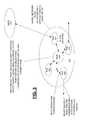
- FIG. 12is a diagram depicting a third example use case for a system for implementing an on-demand computing network environment.
- An organizationdesires to provide third party compute service provider based, disposable Desktops for their employees, with exit point rim devices in Europe 1202 and Brazil 1204 . Management feels that it is important to monitor the activity of the employees, save system log files for their reports, and provide a means of giving access to deployed resources to external clients.
- An administratordecides to set up an Auth Server, Log Server, and Monitoring Server in Rackspace at 1206 and connect those resources to a hub server in New Jersey 1208 . The administrator then deploys exit points rim devices in Brazil 1204 and Amsterdam 1202 .
- Any desktop servers 1208 being built in this projectwill be able to use exit points in Brazil 1204 or Europe 1206 , and have their logs sent to the Chicago 1206 rim device. Access to the desktops will be provided by an in project authentication server, and all deployed resources, from the hub to the exit points will be monitored by the monitoring server deployed in Chicago 1206 .
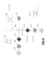
- FIG. 13is a diagram depicting a fourth example use case for a system for implementing an on-demand computing network environment.
- a software as a service (SaaS) provider selling streaming mediais concerned that Internet service providers (ISPs) are doing destination bandwidth throttling.
- the SaaSutilizes a network implementation engine to deploy regional pools of proxy servers 1302 to masquerade their traffic destination, while preserving network performance by making the proxies local to their user base.
- the regional proxy server pools 1302prevent the ISPs from ascertaining that data is coming from the SaaS servers 1304 , the data instead appearing to originate from the proxy server pool 1302 to which a user is connected.
- Such an implementationcould be useful for prevention of throttling of streaming media, such as streaming video content.
- a service at 1304communicates with user clients, indicating a set of proxy servers 1302 with which to communicate.
- a pool of proxy servers 1302receive client stream requests and pass the requests back to the server 1304 .
- the pool of proxy serverscan be cycled aggressively with minimal service disruption.
- the proxy servers 1302present the requests to the server 1304 , with streamed data being provided to the users through the proxy servers 1302 .
- An ISPis unable to ascertain an original source of the streaming data as being the server 1304 instead of the pool of proxy servers 1302 .
- a network implementation engineprovisions dynamic proxy servers in various clouds, connects those servers to fixed brokers, and publishes the list to the server 1304 .
- the portal serverover SSL, directs clients to retrieve data from the dynamic proxy servers located in the various clouds.
- the dynamic proxy serversreceive client stream requests and pass them to fixed broker servers known only by service server 1304 .
- the fixed brokerspass traffic requests back to the data cache.
- the brokersact as a fixed point for minimal disruption to streaming operations.
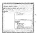
- FIG. 14is a user interface for selecting a project with which to interact. Each depicted project is associated with an on-demand computing network that has been deployed or is being designed.
- FIG. 15is a diagram depicting provisioned computing resources within the on-demand computing network. No resources have been deployed yet in the example of FIG. 15 .
- FIG. 16is a diagram depicting resources available in a pool of acquired resources. The depicted resources can be selected for deployment into an on-demand computing network.
- FIG. 17is a diagram depicting resources deployed into an on-demand computing network, including physical locations of those deployed resources.
- an on-demand computing network environmentcould be implemented without any hubs or joints in a wheel, such as a single rim-to-rim network or a one-rim-to-many-rims network, or a many-rims-to-many-rims network.
- an on-demand computing network environmentcould include one or more of a first rim device connected to a second rim device via one or more joints; multiple joints connected without inclusion of a hub device; a one-to-many joint connection; and a many-to-many joint connection.
Landscapes
- Engineering & Computer Science (AREA)
- Computer Networks & Wireless Communication (AREA)
- Signal Processing (AREA)
- Computer Security & Cryptography (AREA)
- Human Computer Interaction (AREA)
- Computer Hardware Design (AREA)
- Computing Systems (AREA)
- General Engineering & Computer Science (AREA)
- Data Exchanges In Wide-Area Networks (AREA)
Abstract
Description
Claims (26)
Priority Applications (5)
| Application Number | Priority Date | Filing Date | Title |
|---|---|---|---|
| US14/937,978US9935850B1 (en) | 2014-11-18 | 2015-11-11 | Systems and methods for implementing an on-demand computing network environment |
| US15/902,066US10476761B1 (en) | 2014-11-18 | 2018-02-22 | Systems and methods for implementing an on-demand computing network environment |
| US16/587,212US10897409B1 (en) | 2014-11-18 | 2019-09-30 | Systems and methods for implementing an on-demand computing network environment |
| US17/130,046US11381477B1 (en) | 2014-11-18 | 2020-12-22 | Systems and methods for implementing an on-demand computing network environment |
| US17/846,205US12047256B1 (en) | 2014-11-18 | 2022-06-22 | Systems and methods for implementing an on-demand computing network environment |
Applications Claiming Priority (2)
| Application Number | Priority Date | Filing Date | Title |
|---|---|---|---|
| US201462081047P | 2014-11-18 | 2014-11-18 | |
| US14/937,978US9935850B1 (en) | 2014-11-18 | 2015-11-11 | Systems and methods for implementing an on-demand computing network environment |
Related Child Applications (1)
| Application Number | Title | Priority Date | Filing Date |
|---|---|---|---|
| US15/902,066ContinuationUS10476761B1 (en) | 2014-11-18 | 2018-02-22 | Systems and methods for implementing an on-demand computing network environment |
Publications (1)
| Publication Number | Publication Date |
|---|---|
| US9935850B1true US9935850B1 (en) | 2018-04-03 |
Family
ID=61711685
Family Applications (5)
| Application Number | Title | Priority Date | Filing Date |
|---|---|---|---|
| US14/937,978Active2036-03-19US9935850B1 (en) | 2014-11-18 | 2015-11-11 | Systems and methods for implementing an on-demand computing network environment |
| US15/902,066Active2036-02-27US10476761B1 (en) | 2014-11-18 | 2018-02-22 | Systems and methods for implementing an on-demand computing network environment |
| US16/587,212ActiveUS10897409B1 (en) | 2014-11-18 | 2019-09-30 | Systems and methods for implementing an on-demand computing network environment |
| US17/130,046Active2035-11-25US11381477B1 (en) | 2014-11-18 | 2020-12-22 | Systems and methods for implementing an on-demand computing network environment |
| US17/846,205ActiveUS12047256B1 (en) | 2014-11-18 | 2022-06-22 | Systems and methods for implementing an on-demand computing network environment |
Family Applications After (4)
| Application Number | Title | Priority Date | Filing Date |
|---|---|---|---|
| US15/902,066Active2036-02-27US10476761B1 (en) | 2014-11-18 | 2018-02-22 | Systems and methods for implementing an on-demand computing network environment |
| US16/587,212ActiveUS10897409B1 (en) | 2014-11-18 | 2019-09-30 | Systems and methods for implementing an on-demand computing network environment |
| US17/130,046Active2035-11-25US11381477B1 (en) | 2014-11-18 | 2020-12-22 | Systems and methods for implementing an on-demand computing network environment |
| US17/846,205ActiveUS12047256B1 (en) | 2014-11-18 | 2022-06-22 | Systems and methods for implementing an on-demand computing network environment |
Country Status (1)
| Country | Link |
|---|---|
| US (5) | US9935850B1 (en) |
Cited By (1)
| Publication number | Priority date | Publication date | Assignee | Title |
|---|---|---|---|---|
| CN113067732A (en)* | 2021-03-23 | 2021-07-02 | 北京电信规划设计院有限公司 | Internet access behavior management control method |
Citations (38)
| Publication number | Priority date | Publication date | Assignee | Title |
|---|---|---|---|---|
| US20060184998A1 (en)* | 2005-02-14 | 2006-08-17 | Smith Robert D | Systems and methods for automatically configuring and managing network devices and virtual private networks |
| US20060190570A1 (en)* | 2005-02-19 | 2006-08-24 | Cisco Technology, Inc. | Techniques for zero touch provisioning of edge nodes for a virtual private network |
| US20090276771A1 (en)* | 2005-09-15 | 2009-11-05 | 3Tera, Inc. | Globally Distributed Utility Computing Cloud |
| US20100142410A1 (en)* | 2008-12-09 | 2010-06-10 | Olivier Huynh Van | System and method for providing virtual private networks |
| US20100150120A1 (en)* | 2008-09-04 | 2010-06-17 | Ludger Schlicht | Mobile applications for a mobile, broadband, routable internet |
| US20100248719A1 (en)* | 2007-11-23 | 2010-09-30 | Aastra Telecom Schwiez Ag | Self-configuring man-machine interface for a communication terminal |
| US20120005745A1 (en)* | 2010-06-30 | 2012-01-05 | Juniper Networks, Inc. | Vpn network client for mobile device having dynamically translated user home page |
| US20120078643A1 (en)* | 2010-09-23 | 2012-03-29 | International Business Machines Corporation | Geographic governance of data over clouds |
| US20120084184A1 (en)* | 2008-06-05 | 2012-04-05 | Raleigh Gregory G | Enterprise Access Control and Accounting Allocation for Access Networks |
| US20120155325A1 (en)* | 2010-12-17 | 2012-06-21 | Verizon Patent And Licensing Inc. | MOBILE PHONE DOCKING STATION VPNs |
| US20120185925A1 (en)* | 2011-01-13 | 2012-07-19 | International Business Machines Corporation | Systems and Methods for Generating and Validating Configuration Files for Computing Devices |
| US20120239792A1 (en)* | 2011-03-15 | 2012-09-20 | Subrata Banerjee | Placement of a cloud service using network topology and infrastructure performance |
| US20130019089A1 (en)* | 2011-07-15 | 2013-01-17 | International Business Machines Corporation | Applying settings in a cloud computing environment based on geographical region |
| US20130054962A1 (en)* | 2011-08-31 | 2013-02-28 | Deepak Chawla | Policy configuration for mobile device applications |
| US20130117459A1 (en)* | 2011-11-09 | 2013-05-09 | William Biddle HAYNES | System and method of implementing aggregated virtual private network (vpn) settings through a simplified graphical user interface (gui) |
| US20130297933A1 (en)* | 2012-03-29 | 2013-11-07 | Lockheed Martin Corporation | Mobile enterprise smartcard authentication |
| US20130311778A1 (en)* | 2012-05-16 | 2013-11-21 | Cisco Technology, Inc. | System and method for secure cloud service delivery with prioritized services in a network environment |
| US20130332614A1 (en)* | 2012-06-12 | 2013-12-12 | Centurylink Intellectual Property Llc | High Performance Cloud Storage |
| US20130339949A1 (en)* | 2012-06-19 | 2013-12-19 | Bank Of America Corporation | Provisioning of a Virtual Machine by Using a Secured Zone of a Cloud Environment |
| US20140032691A1 (en)* | 2011-10-11 | 2014-01-30 | Citrix Systems, Inc. | Policy-Based Application Management |
| US20140047434A1 (en)* | 2012-08-10 | 2014-02-13 | Adobe Systems Incorporated | Systems and Methods for Cloud Management |
| US8660129B1 (en)* | 2012-02-02 | 2014-02-25 | Cisco Technology, Inc. | Fully distributed routing over a user-configured on-demand virtual network for infrastructure-as-a-service (IaaS) on hybrid cloud networks |
| US20140109177A1 (en)* | 2012-10-15 | 2014-04-17 | Citrix Systems, Inc. | Configuring and providing profiles that manage execution of mobile applications |
| US20150052599A1 (en)* | 2013-08-15 | 2015-02-19 | Mocana Corporation | Gateway device for terminating a large volume of vpn connections |
| US20150113123A1 (en)* | 2013-10-22 | 2015-04-23 | Telefonaktiebolaget L M Ericsson (Publ) | Method and apparatus for performing network discovery |
| US20150163206A1 (en)* | 2013-12-11 | 2015-06-11 | Intralinks, Inc. | Customizable secure data exchange environment |
| US20150237114A1 (en)* | 2014-02-14 | 2015-08-20 | Red Hat, Inc. | Geographic Placement of Application Components by a Multi-Tenant Platform-as-a-Service (PaaS) System |
| US20150256984A1 (en)* | 2004-11-23 | 2015-09-10 | Kodiak Networks, Inc. | PUSH-TO-TALK-OVER-CELLULAR (PoC) SERVICE IN HETEROGENEOUS NETWORKS (HETNETS) AND MULTIMODE SMALL CELL ENVIRONMENTS |
| US20150263865A1 (en)* | 2014-03-12 | 2015-09-17 | Microsoft Corporation | Dynamic and interoperable generation of stateful vpn connection profiles for computing devices |
| US20150281181A1 (en)* | 2014-04-01 | 2015-10-01 | At&T Intellectual Property I, Lp | Method and system to enable a virtual private network client |
| US20160044035A1 (en)* | 2012-04-05 | 2016-02-11 | Arizona Board Of Regents On Behalf Of Arizona State University | Systems and Apparatuses for a Secure Mobile Cloud Framework for Mobile Computing and Communication |
| US20160094560A1 (en)* | 2014-09-30 | 2016-03-31 | Airwatch Llc | Remote processing of mobile applications |
| US9319913B2 (en)* | 2009-01-28 | 2016-04-19 | Headwater Partners I Llc | Wireless end-user device with secure network-provided differential traffic control policy list |
| US20160212012A1 (en)* | 2013-08-30 | 2016-07-21 | Clearpath Networks, Inc. | System and method of network functions virtualization of network services within and across clouds |
| US20160241623A1 (en)* | 2013-10-01 | 2016-08-18 | Argent Line, LLC | Communications platform |
| US9450817B1 (en)* | 2013-03-15 | 2016-09-20 | Juniper Networks, Inc. | Software defined network controller |
| US9507630B2 (en)* | 2012-02-09 | 2016-11-29 | Cisco Technology, Inc. | Application context transfer for distributed computing resources |
| US20170272554A1 (en)* | 2014-03-27 | 2017-09-21 | Pismo Labs Technology Limited | Methods and systems for identifying data sessions at a vpn gateway |
Family Cites Families (41)
| Publication number | Priority date | Publication date | Assignee | Title |
|---|---|---|---|---|
| US8266266B2 (en)* | 1998-12-08 | 2012-09-11 | Nomadix, Inc. | Systems and methods for providing dynamic network authorization, authentication and accounting |
| US7239629B1 (en)* | 1999-12-01 | 2007-07-03 | Verizon Corporate Services Group Inc. | Multiservice network |
| US7818409B2 (en)* | 2002-01-22 | 2010-10-19 | Alcatel-Lucent Usa Inc. | Dynamic virtual private network system and methods |
| US7447203B2 (en)* | 2003-07-29 | 2008-11-04 | At&T Intellectual Property I, L.P. | Broadband access for virtual private networks |
| JP4407452B2 (en)* | 2004-09-29 | 2010-02-03 | 株式会社日立製作所 | Server, VPN client, VPN system, and software |
| US9794225B2 (en)* | 2005-01-31 | 2017-10-17 | Unisys Corporation | Secure network communications in a mobile device over IPsec |
| US7602786B2 (en)* | 2005-07-07 | 2009-10-13 | Cisco Technology, Inc. | Methods and apparatus for optimizing mobile VPN communications |
| JP5111256B2 (en)* | 2008-06-23 | 2013-01-09 | 株式会社日立製作所 | Communication system and server device |
| US8316435B1 (en)* | 2008-08-14 | 2012-11-20 | Juniper Networks, Inc. | Routing device having integrated MPLS-aware firewall with virtual security system support |
| US20100125897A1 (en)* | 2008-11-20 | 2010-05-20 | Rahul Jain | Methods and apparatus for establishing a dynamic virtual private network connection |
| US9049141B2 (en)* | 2008-12-22 | 2015-06-02 | At&T Intellectual Property I, L.P. | User-controlled network video management |
| US9351193B2 (en)* | 2009-01-28 | 2016-05-24 | Headwater Partners I Llc | Intermediate networking devices |
| US20100254385A1 (en)* | 2009-04-07 | 2010-10-07 | Cisco Technology, Inc. | Service Insertion Architecture (SIA) in a Virtual Private Network (VPN) Aware Network |
| CN101599901B (en)* | 2009-07-15 | 2011-06-08 | 杭州华三通信技术有限公司 | Method, system and gateway for remotely accessing MPLS VPN |
| US8650618B2 (en)* | 2009-07-22 | 2014-02-11 | Cisco Technology, Inc. | Integrating service insertion architecture and virtual private network |
| CN102025589B (en)* | 2009-09-18 | 2015-04-01 | 中兴通讯股份有限公司 | Method and system for realizing virtual private network |
| US20110107414A1 (en)* | 2009-11-03 | 2011-05-05 | Broadcom Corporation | System and Method for Location Assisted Virtual Private Networks |
| CN101795235B (en)* | 2010-03-18 | 2014-03-19 | 中兴通讯股份有限公司 | Route map treatment method and operator edge device |
| JP5458999B2 (en)* | 2010-03-19 | 2014-04-02 | 富士通株式会社 | Network management control program, network management control device, and network management control method |
| US10284437B2 (en)* | 2010-09-30 | 2019-05-07 | Efolder, Inc. | Cloud-based virtual machines and offices |
| US9154327B1 (en)* | 2011-05-27 | 2015-10-06 | Cisco Technology, Inc. | User-configured on-demand virtual layer-2 network for infrastructure-as-a-service (IaaS) on a hybrid cloud network |
| US12155634B2 (en)* | 2011-09-09 | 2024-11-26 | Primes Lab Inc. | Metaverse application gateway connection mechanism for use in a private communication architecture |
| US9276825B2 (en)* | 2011-12-14 | 2016-03-01 | Sap Se | Single approach to on-premise and on-demand consumption of services |
| US20140007117A1 (en)* | 2012-06-13 | 2014-01-02 | Bluebox | Methods and apparatus for modifying software applications |
| US20130346839A1 (en)* | 2012-06-20 | 2013-12-26 | Francis Dinha | Private tunnel network portal |
| US8805382B2 (en)* | 2012-07-23 | 2014-08-12 | At&T Intellectual Property I, L.P. | System and method for quality of service in a wireless network environment |
| US9942299B2 (en)* | 2013-03-15 | 2018-04-10 | Yottaa Inc. | System and method for managing multiple variants of an HTTP object |
| US20140330936A1 (en)* | 2013-05-02 | 2014-11-06 | International Business Machines Corporation | Secure isolation of tenant resources in a multi-tenant storage systemwith inter-server communication |
| US9411973B2 (en)* | 2013-05-02 | 2016-08-09 | International Business Machines Corporation | Secure isolation of tenant resources in a multi-tenant storage system using a security gateway |
| US9672503B2 (en)* | 2013-05-21 | 2017-06-06 | Amazon Technologies, Inc. | Bandwidth metering in large-scale networks |
| WO2015103338A1 (en)* | 2013-12-31 | 2015-07-09 | Lookout, Inc. | Cloud-based network security |
| US9674173B2 (en)* | 2014-04-10 | 2017-06-06 | Blue Cedar Networks, Inc. | Automatic certificate enrollment in a special-purpose appliance |
| US9813379B1 (en)* | 2014-05-09 | 2017-11-07 | Amazon Technologies, Inc. | Virtual private gateways using compute instances |
| US20150350377A1 (en)* | 2014-05-29 | 2015-12-03 | Cisco Technology, Inc. | Providing on-demand services |
| US9813488B2 (en)* | 2014-06-25 | 2017-11-07 | Comcast Cable Communications, Llc | Detecting virtual private network usage |
| US10153940B2 (en)* | 2014-09-16 | 2018-12-11 | CloudGenix, Inc. | Methods and systems for detection of asymmetric network data traffic and associated network devices |
| US10182103B2 (en)* | 2014-10-16 | 2019-01-15 | Amazon Technologies, Inc. | On-demand delivery of applications to virtual desktops |
| US9560017B2 (en)* | 2014-11-13 | 2017-01-31 | At&T Intellectual Property I, L.P. | Methods and apparatus to route traffic in a virtual private network |
| US9832606B1 (en)* | 2014-12-16 | 2017-11-28 | Amazon Technologies, Inc. | Modifying user service environments |
| US9684539B1 (en)* | 2014-12-17 | 2017-06-20 | VCE IP Holding Company LLC | Methods, systems, and computer readable mediums for logically remediating infrastructure resource components |
| US20220360566A1 (en)* | 2015-07-31 | 2022-11-10 | Nicira, Inc. | Distributed tunneling for vpn |
- 2015
- 2015-11-11USUS14/937,978patent/US9935850B1/enactiveActive
- 2018
- 2018-02-22USUS15/902,066patent/US10476761B1/enactiveActive
- 2019
- 2019-09-30USUS16/587,212patent/US10897409B1/enactiveActive
- 2020
- 2020-12-22USUS17/130,046patent/US11381477B1/enactiveActive
- 2022
- 2022-06-22USUS17/846,205patent/US12047256B1/enactiveActive
Patent Citations (38)
| Publication number | Priority date | Publication date | Assignee | Title |
|---|---|---|---|---|
| US20150256984A1 (en)* | 2004-11-23 | 2015-09-10 | Kodiak Networks, Inc. | PUSH-TO-TALK-OVER-CELLULAR (PoC) SERVICE IN HETEROGENEOUS NETWORKS (HETNETS) AND MULTIMODE SMALL CELL ENVIRONMENTS |
| US20060184998A1 (en)* | 2005-02-14 | 2006-08-17 | Smith Robert D | Systems and methods for automatically configuring and managing network devices and virtual private networks |
| US20060190570A1 (en)* | 2005-02-19 | 2006-08-24 | Cisco Technology, Inc. | Techniques for zero touch provisioning of edge nodes for a virtual private network |
| US20090276771A1 (en)* | 2005-09-15 | 2009-11-05 | 3Tera, Inc. | Globally Distributed Utility Computing Cloud |
| US20100248719A1 (en)* | 2007-11-23 | 2010-09-30 | Aastra Telecom Schwiez Ag | Self-configuring man-machine interface for a communication terminal |
| US20120084184A1 (en)* | 2008-06-05 | 2012-04-05 | Raleigh Gregory G | Enterprise Access Control and Accounting Allocation for Access Networks |
| US20100150120A1 (en)* | 2008-09-04 | 2010-06-17 | Ludger Schlicht | Mobile applications for a mobile, broadband, routable internet |
| US20100142410A1 (en)* | 2008-12-09 | 2010-06-10 | Olivier Huynh Van | System and method for providing virtual private networks |
| US9319913B2 (en)* | 2009-01-28 | 2016-04-19 | Headwater Partners I Llc | Wireless end-user device with secure network-provided differential traffic control policy list |
| US20120005745A1 (en)* | 2010-06-30 | 2012-01-05 | Juniper Networks, Inc. | Vpn network client for mobile device having dynamically translated user home page |
| US20120078643A1 (en)* | 2010-09-23 | 2012-03-29 | International Business Machines Corporation | Geographic governance of data over clouds |
| US20120155325A1 (en)* | 2010-12-17 | 2012-06-21 | Verizon Patent And Licensing Inc. | MOBILE PHONE DOCKING STATION VPNs |
| US20120185925A1 (en)* | 2011-01-13 | 2012-07-19 | International Business Machines Corporation | Systems and Methods for Generating and Validating Configuration Files for Computing Devices |
| US20120239792A1 (en)* | 2011-03-15 | 2012-09-20 | Subrata Banerjee | Placement of a cloud service using network topology and infrastructure performance |
| US20130019089A1 (en)* | 2011-07-15 | 2013-01-17 | International Business Machines Corporation | Applying settings in a cloud computing environment based on geographical region |
| US20130054962A1 (en)* | 2011-08-31 | 2013-02-28 | Deepak Chawla | Policy configuration for mobile device applications |
| US20140032691A1 (en)* | 2011-10-11 | 2014-01-30 | Citrix Systems, Inc. | Policy-Based Application Management |
| US20130117459A1 (en)* | 2011-11-09 | 2013-05-09 | William Biddle HAYNES | System and method of implementing aggregated virtual private network (vpn) settings through a simplified graphical user interface (gui) |
| US8660129B1 (en)* | 2012-02-02 | 2014-02-25 | Cisco Technology, Inc. | Fully distributed routing over a user-configured on-demand virtual network for infrastructure-as-a-service (IaaS) on hybrid cloud networks |
| US9507630B2 (en)* | 2012-02-09 | 2016-11-29 | Cisco Technology, Inc. | Application context transfer for distributed computing resources |
| US20130297933A1 (en)* | 2012-03-29 | 2013-11-07 | Lockheed Martin Corporation | Mobile enterprise smartcard authentication |
| US20160044035A1 (en)* | 2012-04-05 | 2016-02-11 | Arizona Board Of Regents On Behalf Of Arizona State University | Systems and Apparatuses for a Secure Mobile Cloud Framework for Mobile Computing and Communication |
| US20130311778A1 (en)* | 2012-05-16 | 2013-11-21 | Cisco Technology, Inc. | System and method for secure cloud service delivery with prioritized services in a network environment |
| US20130332614A1 (en)* | 2012-06-12 | 2013-12-12 | Centurylink Intellectual Property Llc | High Performance Cloud Storage |
| US20130339949A1 (en)* | 2012-06-19 | 2013-12-19 | Bank Of America Corporation | Provisioning of a Virtual Machine by Using a Secured Zone of a Cloud Environment |
| US20140047434A1 (en)* | 2012-08-10 | 2014-02-13 | Adobe Systems Incorporated | Systems and Methods for Cloud Management |
| US20140109177A1 (en)* | 2012-10-15 | 2014-04-17 | Citrix Systems, Inc. | Configuring and providing profiles that manage execution of mobile applications |
| US9450817B1 (en)* | 2013-03-15 | 2016-09-20 | Juniper Networks, Inc. | Software defined network controller |
| US20150052599A1 (en)* | 2013-08-15 | 2015-02-19 | Mocana Corporation | Gateway device for terminating a large volume of vpn connections |
| US20160212012A1 (en)* | 2013-08-30 | 2016-07-21 | Clearpath Networks, Inc. | System and method of network functions virtualization of network services within and across clouds |
| US20160241623A1 (en)* | 2013-10-01 | 2016-08-18 | Argent Line, LLC | Communications platform |
| US20150113123A1 (en)* | 2013-10-22 | 2015-04-23 | Telefonaktiebolaget L M Ericsson (Publ) | Method and apparatus for performing network discovery |
| US20150163206A1 (en)* | 2013-12-11 | 2015-06-11 | Intralinks, Inc. | Customizable secure data exchange environment |
| US20150237114A1 (en)* | 2014-02-14 | 2015-08-20 | Red Hat, Inc. | Geographic Placement of Application Components by a Multi-Tenant Platform-as-a-Service (PaaS) System |
| US20150263865A1 (en)* | 2014-03-12 | 2015-09-17 | Microsoft Corporation | Dynamic and interoperable generation of stateful vpn connection profiles for computing devices |
| US20170272554A1 (en)* | 2014-03-27 | 2017-09-21 | Pismo Labs Technology Limited | Methods and systems for identifying data sessions at a vpn gateway |
| US20150281181A1 (en)* | 2014-04-01 | 2015-10-01 | At&T Intellectual Property I, Lp | Method and system to enable a virtual private network client |
| US20160094560A1 (en)* | 2014-09-30 | 2016-03-31 | Airwatch Llc | Remote processing of mobile applications |
Cited By (2)
| Publication number | Priority date | Publication date | Assignee | Title |
|---|---|---|---|---|
| CN113067732A (en)* | 2021-03-23 | 2021-07-02 | 北京电信规划设计院有限公司 | Internet access behavior management control method |
| CN113067732B (en)* | 2021-03-23 | 2022-08-05 | 北京电信规划设计院有限公司 | Online behavior management control method |
Also Published As
| Publication number | Publication date |
|---|---|
| US10897409B1 (en) | 2021-01-19 |
| US10476761B1 (en) | 2019-11-12 |
| US12047256B1 (en) | 2024-07-23 |
| US11381477B1 (en) | 2022-07-05 |
Similar Documents
| Publication | Publication Date | Title |
|---|---|---|
| US12212635B2 (en) | Traffic forwarding and disambiguation by using local proxies and addresses | |
| US10880400B2 (en) | Programming a data network device using user defined scripts | |
| US10454879B2 (en) | Methods and systems for processing a DNS request | |
| JP5711754B2 (en) | Smart client routing | |
| JP2018518862A (en) | System and method for providing virtual interfaces and advanced smart routing in a global virtual network (GVN) | |
| US10659255B1 (en) | Identity-based virtual private network tunneling | |
| US11818200B2 (en) | Hybrid cloud computing network management with synchronization features across different cloud service providers | |
| WO2015192563A1 (en) | Method and device for implementing load balancing and load balancing service system | |
| US11996983B1 (en) | Network appliance for providing configurable virtual private network connections | |
| US20230388383A1 (en) | Systems and methods for routing remote application data | |
| US12381941B1 (en) | Systems and methods for implementing an on-demand computing network environment utilizing a bridge device | |
| US12047256B1 (en) | Systems and methods for implementing an on-demand computing network environment | |
| CN110830317B (en) | Internet access behavior management system, equipment and method | |
| US12041105B1 (en) | Systems and methods for implementing an on-demand computing network environment | |
| US12375353B1 (en) | Systems and methods for providing a computer network having migratable nodes |
Legal Events
| Date | Code | Title | Description |
|---|---|---|---|
| AS | Assignment | Owner name:BERRYVILLE HOLDINGS, LLC, VIRGINIA Free format text:ASSIGNMENT OF ASSIGNORS INTEREST;ASSIGNORS:DELANEY, CHRISTOPHER EDWARD;JACOBS, CARL BAILEY;JURADO, CHAVA LOUIS;AND OTHERS;SIGNING DATES FROM 20151209 TO 20151214;REEL/FRAME:037337/0590 | |
| AS | Assignment | Owner name:DEXTER EDWARD, LLC, VIRGINIA Free format text:ASSIGNMENT OF ASSIGNORS INTEREST;ASSIGNOR:JACKSON, CHRISTOPHER EDWARD;REEL/FRAME:037462/0785 Effective date:20160112 | |
| AS | Assignment | Owner name:BERRYVILLE HOLDINGS, LLC, VIRGINIA Free format text:ASSIGNMENT OF ASSIGNORS INTEREST;ASSIGNOR:DEXTER EDWARD, LLC;REEL/FRAME:037676/0185 Effective date:20160128 | |
| STCF | Information on status: patent grant | Free format text:PATENTED CASE | |
| FEPP | Fee payment procedure | Free format text:SURCHARGE FOR LATE PAYMENT, SMALL ENTITY (ORIGINAL EVENT CODE: M2554); ENTITY STATUS OF PATENT OWNER: SMALL ENTITY | |
| MAFP | Maintenance fee payment | Free format text:PAYMENT OF MAINTENANCE FEE, 4TH YR, SMALL ENTITY (ORIGINAL EVENT CODE: M2551); ENTITY STATUS OF PATENT OWNER: SMALL ENTITY Year of fee payment:4 | |
| AS | Assignment | Owner name:CYBER IP HOLDINGS, LLC, VIRGINIA Free format text:ASSIGNMENT OF ASSIGNORS INTEREST;ASSIGNOR:BERRYVILLE HOLDINGS, LLC;REEL/FRAME:059797/0483 Effective date:20220316 |