US9935498B2 - Communication efficiency with an implantable medical device using a circulator and a backscatter signal - Google Patents
Communication efficiency with an implantable medical device using a circulator and a backscatter signalDownload PDFInfo
- Publication number
- US9935498B2 US9935498B2US13/625,922US201213625922AUS9935498B2US 9935498 B2US9935498 B2US 9935498B2US 201213625922 AUS201213625922 AUS 201213625922AUS 9935498 B2US9935498 B2US 9935498B2
- Authority
- US
- United States
- Prior art keywords
- signal
- backscatter
- imd
- charging
- backscatter signal
- Prior art date
- Legal status (The legal status is an assumption and is not a legal conclusion. Google has not performed a legal analysis and makes no representation as to the accuracy of the status listed.)
- Active, expires
Links
Images


Classifications
- H—ELECTRICITY
- H02—GENERATION; CONVERSION OR DISTRIBUTION OF ELECTRIC POWER
- H02J—CIRCUIT ARRANGEMENTS OR SYSTEMS FOR SUPPLYING OR DISTRIBUTING ELECTRIC POWER; SYSTEMS FOR STORING ELECTRIC ENERGY
- H02J50/00—Circuit arrangements or systems for wireless supply or distribution of electric power
- H02J50/10—Circuit arrangements or systems for wireless supply or distribution of electric power using inductive coupling
- H02J50/12—Circuit arrangements or systems for wireless supply or distribution of electric power using inductive coupling of the resonant type
- A—HUMAN NECESSITIES
- A61—MEDICAL OR VETERINARY SCIENCE; HYGIENE
- A61B—DIAGNOSIS; SURGERY; IDENTIFICATION
- A61B5/00—Measuring for diagnostic purposes; Identification of persons
- A61B5/0002—Remote monitoring of patients using telemetry, e.g. transmission of vital signals via a communication network
- A61B5/0031—Implanted circuitry
- A—HUMAN NECESSITIES
- A61—MEDICAL OR VETERINARY SCIENCE; HYGIENE
- A61N—ELECTROTHERAPY; MAGNETOTHERAPY; RADIATION THERAPY; ULTRASOUND THERAPY
- A61N1/00—Electrotherapy; Circuits therefor
- A61N1/18—Applying electric currents by contact electrodes
- A61N1/32—Applying electric currents by contact electrodes alternating or intermittent currents
- A61N1/36—Applying electric currents by contact electrodes alternating or intermittent currents for stimulation
- A61N1/372—Arrangements in connection with the implantation of stimulators
- A61N1/37211—Means for communicating with stimulators
- A61N1/37217—Means for communicating with stimulators characterised by the communication link, e.g. acoustic or tactile
- A61N1/37223—Circuits for electromagnetic coupling
- A—HUMAN NECESSITIES
- A61—MEDICAL OR VETERINARY SCIENCE; HYGIENE
- A61N—ELECTROTHERAPY; MAGNETOTHERAPY; RADIATION THERAPY; ULTRASOUND THERAPY
- A61N1/00—Electrotherapy; Circuits therefor
- A61N1/18—Applying electric currents by contact electrodes
- A61N1/32—Applying electric currents by contact electrodes alternating or intermittent currents
- A61N1/36—Applying electric currents by contact electrodes alternating or intermittent currents for stimulation
- A61N1/372—Arrangements in connection with the implantation of stimulators
- A61N1/378—Electrical supply
- A61N1/3787—Electrical supply from an external energy source
- H—ELECTRICITY
- H02—GENERATION; CONVERSION OR DISTRIBUTION OF ELECTRIC POWER
- H02J—CIRCUIT ARRANGEMENTS OR SYSTEMS FOR SUPPLYING OR DISTRIBUTING ELECTRIC POWER; SYSTEMS FOR STORING ELECTRIC ENERGY
- H02J50/00—Circuit arrangements or systems for wireless supply or distribution of electric power
- H02J50/10—Circuit arrangements or systems for wireless supply or distribution of electric power using inductive coupling
- H—ELECTRICITY
- H02—GENERATION; CONVERSION OR DISTRIBUTION OF ELECTRIC POWER
- H02J—CIRCUIT ARRANGEMENTS OR SYSTEMS FOR SUPPLYING OR DISTRIBUTING ELECTRIC POWER; SYSTEMS FOR STORING ELECTRIC ENERGY
- H02J50/00—Circuit arrangements or systems for wireless supply or distribution of electric power
- H02J50/70—Circuit arrangements or systems for wireless supply or distribution of electric power involving the reduction of electric, magnetic or electromagnetic leakage fields
- H—ELECTRICITY
- H02—GENERATION; CONVERSION OR DISTRIBUTION OF ELECTRIC POWER
- H02J—CIRCUIT ARRANGEMENTS OR SYSTEMS FOR SUPPLYING OR DISTRIBUTING ELECTRIC POWER; SYSTEMS FOR STORING ELECTRIC ENERGY
- H02J50/00—Circuit arrangements or systems for wireless supply or distribution of electric power
- H02J50/80—Circuit arrangements or systems for wireless supply or distribution of electric power involving the exchange of data, concerning supply or distribution of electric power, between transmitting devices and receiving devices
- H—ELECTRICITY
- H02—GENERATION; CONVERSION OR DISTRIBUTION OF ELECTRIC POWER
- H02J—CIRCUIT ARRANGEMENTS OR SYSTEMS FOR SUPPLYING OR DISTRIBUTING ELECTRIC POWER; SYSTEMS FOR STORING ELECTRIC ENERGY
- H02J50/00—Circuit arrangements or systems for wireless supply or distribution of electric power
- H02J50/90—Circuit arrangements or systems for wireless supply or distribution of electric power involving detection or optimisation of position, e.g. alignment
- H—ELECTRICITY
- H02—GENERATION; CONVERSION OR DISTRIBUTION OF ELECTRIC POWER
- H02J—CIRCUIT ARRANGEMENTS OR SYSTEMS FOR SUPPLYING OR DISTRIBUTING ELECTRIC POWER; SYSTEMS FOR STORING ELECTRIC ENERGY
- H02J7/00—Circuit arrangements for charging or depolarising batteries or for supplying loads from batteries
- H02J7/00032—Circuit arrangements for charging or depolarising batteries or for supplying loads from batteries characterised by data exchange
- H02J7/00034—Charger exchanging data with an electronic device, i.e. telephone, whose internal battery is under charge
- H02J7/025—
- H04B5/0031—
- H04B5/0037—
- H—ELECTRICITY
- H04—ELECTRIC COMMUNICATION TECHNIQUE
- H04B—TRANSMISSION
- H04B5/00—Near-field transmission systems, e.g. inductive or capacitive transmission systems
- H04B5/40—Near-field transmission systems, e.g. inductive or capacitive transmission systems characterised by components specially adapted for near-field transmission
- H04B5/45—Transponders
- H—ELECTRICITY
- H04—ELECTRIC COMMUNICATION TECHNIQUE
- H04B—TRANSMISSION
- H04B5/00—Near-field transmission systems, e.g. inductive or capacitive transmission systems
- H04B5/70—Near-field transmission systems, e.g. inductive or capacitive transmission systems specially adapted for specific purposes
- H04B5/79—Near-field transmission systems, e.g. inductive or capacitive transmission systems specially adapted for specific purposes for data transfer in combination with power transfer
- A—HUMAN NECESSITIES
- A61—MEDICAL OR VETERINARY SCIENCE; HYGIENE
- A61B—DIAGNOSIS; SURGERY; IDENTIFICATION
- A61B2560/00—Constructional details of operational features of apparatus; Accessories for medical measuring apparatus
- A61B2560/02—Operational features
- A61B2560/0204—Operational features of power management
- H—ELECTRICITY
- H02—GENERATION; CONVERSION OR DISTRIBUTION OF ELECTRIC POWER
- H02J—CIRCUIT ARRANGEMENTS OR SYSTEMS FOR SUPPLYING OR DISTRIBUTING ELECTRIC POWER; SYSTEMS FOR STORING ELECTRIC ENERGY
- H02J2310/00—The network for supplying or distributing electric power characterised by its spatial reach or by the load
- H02J2310/10—The network having a local or delimited stationary reach
- H02J2310/20—The network being internal to a load
- H02J2310/23—The load being a medical device, a medical implant, or a life supporting device
- H02J5/005—
- H04B5/0075—
- H—ELECTRICITY
- H04—ELECTRIC COMMUNICATION TECHNIQUE
- H04B—TRANSMISSION
- H04B5/00—Near-field transmission systems, e.g. inductive or capacitive transmission systems
- H04B5/20—Near-field transmission systems, e.g. inductive or capacitive transmission systems characterised by the transmission technique; characterised by the transmission medium
- H04B5/24—Inductive coupling
Definitions
- the present disclosureis generally related to charging, and communicating with, implantable medical devices.
- Implantable medical devicesinclude a battery. If the battery is rechargeable, the implantable medical device may include charging components to receive power from an external source to recharge the battery.
- the implantable medical devicemay include a coil that is operative to inductively couple with an external coil. Providing power via inductive coupling may require that the coil of the implantable medical device and the external coil be relatively close to one another (e.g., within a distance over which a magnetic field is relatively strong). Further, inductive coupling may be less efficient when the coil of the implantable medical device and the external coil are not aligned or oriented properly. Further, component value variations in implantable medical device circuitry and variations in tissue properties from patient to patient affect the communication efficiency of implantable medical devices.
- a devicemay be used to charge or communicate with an implantable medical device (IMD) that is implanted within tissue of a patient.
- IMDimplantable medical device
- a primary antenna of the devicemay transmit a charging signal and/or a communication signal that is received by an antenna of the IMD.
- One of more components of the IMDmay generate a backscatter signal in response to the signal.
- one or more circuit componentse.g., diodes
- the one or more componentsmay generate the backscatter signal while generating the direct-current signal from the charging signal.
- impedance mismatch between the antenna and other components of the IMDmay generate the backscatter signal in response to the charging and/or communication signal.
- the backscatter signalmay be used to determine information related to the IMD.
- the backscatter signalmay convey information related to a charge state of a charge storage element, such as a rechargeable battery, of the IMD.
- the backscatter signalmay be detected and processed to extract and/or estimate the information related to the IMD.
- a particular embodimentrelates to a device that includes a primary antenna configured to communicate a signal to an antenna of an implantable medical device.
- a circulatoris coupled to the primary antenna. The circulator enables the signal to pass from a transmitter to the primary antenna. The circulator also enables a backscatter signal from the implantable medical device to pass from the primary antenna to a receiver.
- a processoris coupled to the receiver and is configured to determine, based on the backscatter signal, an improved impedance value for a component of the implantable medical device and/or an improved frequency for the signal communicated to the implantable medical device, to improve communication efficiency of the signal to the implantable medical device.
- Another particular embodimentrelates to a method that includes generating a signal at a transmitter of a device and applying the signal to a primary antenna of the device via a circulator.
- the methodfurther includes communicating the signal to an antenna of an implantable medical device.
- the methodfurther includes receiving, at the primary antenna, a backscatter signal generated by a circuit component of the implantable medical device responsive to the signal and providing the backscatter signal to a receiver of the device via the circulator.
- the methodfurther includes determining, based on the backscatter signal, an improved impedance value for a component of the implantable medical device and/or an improved frequency for the signal communicated to the implantable medical device, to improve communication efficiency of the signal to the implantable medical device.
- Another particular embodimentrelates to an apparatus that includes means for generating a signal at a device and means for communicating the signal to an antenna of an implantable medical device.
- the apparatusalso includes means for receiving a backscatter signal generated by a circuit component of the implantable medical device responsive to the signal.
- the apparatusfurther includes means for processing the backscatter signal and determining, based on the backscatter signal, an improved impedance value for a component of the implantable medical device and/or an improved frequency for the signal communicated to the implantable medical device, to improve communication efficiency of the signal to the implantable medical device.
- FIG. 1is a block diagram of a system including an external device and an implantable medical device according to a first exemplary embodiment.
- FIG. 2is a block diagram of a system including the external device and the implantable medical device according to a second exemplary embodiment.
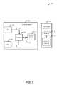
- FIG. 3is a block diagram of a system including the external device and the implantable medical device according to a third exemplary embodiment.
- FIG. 4is a flow chart of a method of generating a signal and receiving a backscatter signal according to a first particular embodiment.
- FIG. 5is a flow chart of a method of generating a signal and receiving a backscatter signal according to a second particular embodiment.
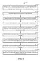
- FIG. 6is a flow chart of a method of generating a signal and receiving a backscatter signal according to a third particular embodiment.
- FIG. 7is a flow chart of a method of generating a signal and receiving a backscatter signal according to a fourth particular embodiment.
- FIG. 8is a flow chart of a method of generating a signal and receiving a backscatter signal according to a fifth particular embodiment.
- FIG. 9is a flow chart of a method of generating a signal and receiving a backscatter signal according to a sixth particular embodiment.
- FIG. 1a block diagram of a system 100 including an external device 102 and an implantable medical device (IMD) 120 is shown according to a particular embodiment.
- the external device 102is configured to send a signal to the IMD 120 and to receive a backscatter signal from the IMD 120 .
- the IMD 120is configured to generate the backscatter signal responsive to the signal from the external device 102 .
- the external device 102includes a transmitter 104 , a receiver 106 , a circulator 108 , and a primary antenna 110 .
- the transmitter 104is coupled to the circulator 108 via a line 112 .
- the transmitter 104may send the signal to the circulator 108 via the line 112 .
- the receiver 106is coupled to the circulator 108 via a line 114 .
- the receiver 106may receive the backscatter signal from the circulator 108 via the line 114 .
- the circulator 108is coupled to the primary antenna 110 .
- the circulator 108enables the signal to pass from the transmitter 104 to the primary antenna 110 .
- the circulator 108also enables the backscatter signal from the IMD 120 to pass from the primary antenna 110 to the receiver 106 .
- the circulator 108is a multiport device that allows a signal entering at one port of the device to pass primarily to a next port of the device in a rotation. To illustrate, the circulator 108 allows the signal received at a first port coupled to the transmitter 104 to pass to a second port coupled to the primary antenna 110 , but blocks all or most of the signal received at the first port from passing to a third port coupled to the receiver 106 . The circulator 108 also allows a second signal (e.g., the backscatter signal) received at the second port coupled to the primary antenna 110 to pass to the third port coupled to the receiver 106 , but blocks all or most of the second signal received at the second port from passing to the first port coupled to the transmitter 104 .
- a second signale.g., the backscatter signal
- the circulator 108may enable simultaneous or concurrent transmission of the signal and receipt of the backscatter signal.
- the circulator 108may allow a relatively small portion of the signal to pass to the receiver 106 as a leakage signal.
- the leakage signalmay be of sufficiently low power that the backscatter signal can be detected by the receiver 106 .
- the IMD 120includes the antenna 122 and a component 124 that is responsive to the signal.
- the antenna 122is coupled to the component 124 .
- the component 124 that is responsive to the signalmay include a circuit element or a set of circuit elements that generate the backscatter signal responsive to the signal.
- the component 124 that is responsive to the signalmay perform other functions of the IMD 120 .
- the component 124may include or be included within a matching network, a charge storage component, or another component of the IMD 120 .
- the transmitter 104may provide the signal to the circulator 108 via the line 112 .
- the circulator 108may provide the signal to the primary antenna 110 .
- the primary antenna 110may radiatively transfer the signal to the antenna 122 of the IMD 120 .
- the antenna 122may provide the signal to the component 124 .
- the component 124may perform a function of the IMD 120 using, based on, or responsive to the signal.
- the component 124 of the IMD 120may also generate the backscatter signal responsive to the signal. For example, impedance mismatch between the antenna 122 and the component 124 may generate the backscatter signal when the signal is received. In another example, the component 124 may generate the backscatter signal by itself when the signal is received.
- the component 124may include or be coupled to a circuit that includes one or more circuit elements that generate the backscatter signal.
- circuit elements that may generate the backscatter signalinclude diodes of a rectifier circuit.
- the antenna 122may transmit the backscatter signal, which may be received by the primary antenna 110 .
- the primary antenna 110may transfer the backscatter signal to the circulator 108 .
- the circulator 108may pass the backscatter signal to the receiver 106 on the line 114 .
- the backscatter signalhas the same frequency as the signal.
- the backscatter signalmay be processed to extract and/or estimate information regarding the IMD 120 .
- the receiver 106may process the backscatter signal and/or pass the backscatter signal to another component for processing.
- the receiver 106may pass the backscatter signal to a processor as is described with respect to FIG. 2 .
- the receiver 106may pass the backscatter signal or data descriptive of the backscatter signal to a processor (not shown) that is external to the external device 102 .
- the backscatter signalmay be used to detect presence of the IMD 120 within tissue of a patient.
- the backscatter signalmay include, or may be used to deduce, information related to tuning of a matching network of the IMD 120 .
- a characteristic of the backscatter signal(such as a magnitude of the backscatter signal) may change as tuning of the matching network changes.
- the backscatter signalmay include, or may be used to deduce, information related to charging efficiency of a charge storage element (as described further with reference to FIG. 2 ).
- a characteristic of the backscatter signal(such as a magnitude of the backscatter signal) may change as radiofrequency (RF) charging efficiency of the charge storage element changes.
- RFradiofrequency
- the backscatter signalmay include, or may be used to deduce, information related to selecting a frequency for communication with the IMD 120 (as described in more detail with reference to FIG. 3 ).
- the backscatter signalmay be strongest when the signal received by the component 124 is strongest. That is, when the signal is communicated more efficiently to the component 124 , the component 124 may generate a stronger backscatter signal.
- a frequency sweep of available communication channelsmay be performed by the transmitter 104 .
- the receiver 106may receive a backscatter signal corresponding to each channel. A channel may be selected that corresponds to a strongest backscatter signal received by the receiver.
- Use of the backscatter signal to extract and/or estimate information about the IMD 120may enable determination of the information without the IMD 120 using stored energy to generate and to send a signal to convey the information about the IMD 120 to the external device 102 .
- use of the backscatter signalmay substantially reduce power consumption associated with generating and sending a signal to the external device 102 to convey the information about the IMD 120 .
- the external device 102includes the transmitter 104 , the receiver 106 , the circulator 108 , and the primary antenna 110 .
- the external device 102also includes a processor 202 and a memory device 204 that includes instructions 208 .
- the memory device 204may be a non-transitory machine-readable memory device.
- the memory device 204may also store data.
- the memory device 204is coupled to the processor 202 .
- the processor 202is coupled to the transmitter 104 and to the receiver 106 via a line 210 .
- the transmitter 104is coupled to the circulator 108 via the line 112
- the receiver 106is coupled to the circulator 108 via the line 114
- the circulator 108is coupled to the primary antenna 110 .
- the line 210 , the line 112 , and the line 114are each shown as a single line, each of the line 210 , the line 112 , and the line 114 may represent multiple lines.
- the processor 202may be configured to send a control signal to the transmitter 104 .
- the processor 202may send the control signal to the transmitter 104 via the line 210 to instruct the transmitter 104 to send the signal to the IMD 120 .
- the processor 202may also be configured to receive the backscatter signal from the receiver 106 via the line 210 .
- the transmitter 104may be configured to send the signal to the IMD 120 in response to the control signal from the processor 202 .
- the transmitter 104may send the signal to the IMD 120 via the circulator 108 via the line 112 .
- the circulator 108may be configured to pass the signal from the transmitter 104 to the primary antenna 110 .
- the primary antenna 110may be configured to radiatively communicate the signal to the antenna 122 of the IMD 120 .
- the IMD 120includes the antenna 122 and the component 124 that is responsive to the signal.
- the component 124 that is responsive to the signalmay include, be included within, or correspond to a tunable matching network 220 , a charge storage element 222 , a rectifier 224 , a circuit component 226 (such as a diode) of the rectifier 224 , a therapy delivery unit 228 (e.g., a stimulation unit), or a combination thereof.
- the antenna 122is coupled to the tunable matching network 220 .
- the tunable matching network 220is coupled to the charge storage element 222 .
- the charge storage element 222is coupled to the therapy delivery unit 228 .
- the therapy delivery unit 228may receive power to operate from the charge storage element 222 .
- the tunable matching network 220includes one or more capacitors, one or more inductors, one or more resistors, or any combination thereof. Impedance of the tunable matching network 220 may be adjusted to reduce signal power loss due to signal reflection that may be caused by impedance mismatch between the antenna 122 and the tunable matching network 220 . To illustrate, the impedance of the tunable matching network 220 may be adjusted to provide improved impedance matching between the antenna 122 , the tunable matching network 220 , and one or more other components of the IMD 120 , such as the charge storage element 222 or the therapy delivery unit 228 . For example, the impedance of the tunable matching network 220 may be adjusted by adjusting a capacitance of one or more capacitors of the tunable matching network 220 . Impedance mismatch may reduce charging efficiency at the charge storage element 222 .
- a characteristic of the backscatter signal generated by the IMD 120 in response to the signalis related to the impedance matching between the antenna 122 and the tunable matching network 220 .
- the processor 202may be operable to determine, based on the characteristic of the backscatter signal whether the impedance matching between the antenna 122 and the tunable matching network 220 is within acceptable tolerances. When the impedance matching between the antenna 122 and the tunable matching network 220 is not within acceptable tolerances, the processor 202 may cause the transmitter 104 to send a tuning signal to the IMD 120 . In response to the tuning signal, the impedance of the tunable matching network 220 may be modified. Thus, the backscatter signal may be used to improve charging efficiency of the charge storage element 222 by reducing impedance mismatch.
- the processor 202may cause the transmitter 104 to change a frequency of the signal, based on the backscatter signal, to reduce impedance mismatch at the IMD 120 .
- the processor 202may cause the transmitter 104 to perform a frequency sweep of particular channels or frequency bands.
- the external device 102may communicate with the IMD 120 using a selected channel of multiple available channels.
- the available channelsmay correspond to frequency bands that are authorized (e.g., by an appropriate governmental agency, such as the Federal Communication Commission in the United States) for use for medical device communications or other relatively low power, short range communications.
- the transmitter 104may perform the frequency sweep by transmitting a first signal to the IMD 120 using a first channel of the available channels, subsequently transmitting a second signal to the IMD 120 using a second channel of the available channels, and so forth, through each of the available channels or through a subset of the available channels.
- the receiver 106may receive a backscatter signal corresponding to each signal transmitted during the frequency sweep (e.g., a first backscatter signal corresponding to the first signal, a second backscatter signal corresponding to the second signal, and so forth).
- the receiver 106 or the processor 202may select a particular channel to be used to communicate with the IMD 120 based on the backscatter signals received during the frequency sweep. For example, a channel that corresponds to a backscatter signal that had a largest amplitude (e.g., a highest power backscatter signal) may be selected.
- the receiver 106may receive a leakage signal corresponding to each signal transmitted during the frequency sweep.
- a signal detectedmay include the backscatter signal and the leakage signal.
- the receiver 106 or the processor 202may select a particular channel to be used to communicate with the IMD 120 that had a largest difference in amplitude between the backscatter signal and the leakage signal.
- the charge storage element 222includes or is coupled to the rectifier 224 .
- the rectifier 224may be configured to rectify the signal from the external device 102 to generate a DC signal to charge the charge storage element 222 .
- the rectifier 224may include one or more circuit components 226 that generate a backscatter signal responsive to the signal.
- the circuit components 226may include one or more diodes or other circuit elements that are characterized by a non-linear current and voltage relationship.
- the rectifier 224may also include one or more capacitors.
- the charge storage element 222may include a rechargeable battery, a capacitor, another charge storage device, or a combination thereof.
- circuit components coupled to the antenna 122 through the tunable matching network 220may generate or contribute to generation of the backscatter signal.
- the one or more diodes of the circuit components 226may generate the backscatter signal.
- the therapy delivery unit 228is configured to deliver therapy to a patient in which the implantable medical device 120 is implanted using power from the charge storage element 222 .
- the therapy delivery unit 228may deliver the therapy as one or more electrical signals applied to tissue of the patient, by delivery of a chemical to the patient, by other therapy delivery mechanisms, or a combination thereof.
- the therapy delivery unit 228may deliver the therapy as an electrical signal on a therapy line 230 that is coupled to one or more electrodes positioned proximate to target tissue of the patient.
- the therapy delivery unit 228may include a drug delivery pump that is operable to deliver a drug to the patient.
- the backscatter signalhas the same frequency as the signal transmitted by the external device 102 .
- the receiver 106may have difficulty distinguishing the backscatter signal from the signal.
- the primary antenna 110 of the external device 102may be configured to receive the backscatter signal from the IMD 120 and to send the received backscatter signal to the receiver 106 via the circulator 108 .
- the circulator 108may be configured to pass the backscatter signal from the primary antenna 110 to the receiver 106 .
- the circulator 108may inhibit the signal from passing from the transmitter 104 to the receiver 106 (although a portion of the signal may pass from the transmitter 104 to the receiver 106 as a leakage signal).
- the circulator 108enables the receiver 106 to distinguish the backscatter signal simultaneously or concurrently with transmission of the signal.
- the receiver 106may send the backscatter signal to the processor 202 .
- the backscatter signalmay include or may be used to deduce information related to the IMD 120 .
- the processor 202may execute the instructions 208 stored in the memory device 204 .
- the processor 202may be configured to estimate, based on the backscatter signal, impedance mismatch at the IMD 120 .
- the processor 202may be configured to select a channel for use to communicate with the IMD 120 based on the backscatter signal.
- the processor 202may be configured to estimate, based on the backscatter signal, charging efficiency of the charging signal with respect to the charge storage element 222 . After estimating the charging efficiency of the charging signal, the processor 202 may adjust a frequency of the charging signal. For example, the processor 202 may send a control signal to the transmitter 104 to instruct the transmitter 104 to increase or to decrease the frequency of the charging signal. The processor 202 may also, or in the alternative, send a control signal to the transmitter 104 to instruct the transmitter 104 to set the frequency of the charging signal to a particular value.
- the processor 202may cause the tunable matching network 220 of the IMD 120 to be adjusted to improve charging efficiency of the charging signal. For example, the processor 202 may generate an output signal to indicate whether the impedance of the tunable matching network 220 should be increased or decreased.
- the processor 202may be configured to perform a frequency sweep of the charging signal to identify, based on the backscatter signal, a particular frequency associated with an improved charging efficiency relative to other frequencies of the charging signal. For example, the processor 202 may send a control signal to the transmitter 104 to instruct the transmitter 104 to send the charging signal at a specified frequency to the IMD 120 . The processor 202 may repeatedly send control signals to the transmitter 104 , each control signal indicating a different frequency of the charging signal. The processor 202 may process the backscatter signal from the IMD 120 corresponding to each frequency of the charging signal.
- the processor 202may identify a particular frequency of the charging signal associated with an improved charging efficiency.
- the processor 202may perform the frequency sweep of the charging signal repeatedly during charging of the IMD 120 . For example, as the charge state of the charge storage element 222 changes, recharging efficiency of the charging signal may change. Accordingly, the processor 202 may periodically or occasionally (e.g., based on a detected change in the charge state) repeat the frequency sweep of the charging signal to select a new frequency of the charging signal that is associated with improved charging efficiency.
- the processor 202may detect presence of the IMD 120 that is near the external device 102 based on the backscatter signal. For example, the processor 202 may determine that the IMD 120 is within a particular distance of the external device 102 based on a signal strength of the backscatter signal. The processor 202 may also, or in the alternative, determine that the IMD 120 is not near the external device 102 if the processor 202 does not detect the backscatter signal or detects a weak backscatter signal. Based on the detected presence of the IMD 120 , the processor 202 may generate an output signal to provide information about the distance of the external device 102 relative to the IMD 120 . For example, the external device 102 may provide an indication to adjust a distance between the external device 102 and the IMD 120 .
- the processor 202may send a control signal to the transmitter 104 to instruct the transmitter 104 to cease generation of the charging signal, to terminate sending the charging signal to the primary antenna 110 , or both in response to the backscatter signal.
- the processor 202may send the control signal to the transmitter 104 instructing the transmitter 104 to cease generation of the charging signal after estimating the charge state of the charge storage element 222 based on the backscatter signal.
- the backscatter signalmay be used to determine information about charging efficiency of the charging signal. A portion of energy of the charging signal that does not result in charging of the charge storage element 222 may be lost as heat, which may increase a temperature of the IMD 120 .
- the processormay cease application of the charging signal to the IMD 120 based on information related to temperature rise of the IMD 120 , such as a time of application of the charging signal and the estimated efficiency of the charging signal.
- information related to temperature rise of the IMD 120such as a time of application of the charging signal and the estimated efficiency of the charging signal.
- the processor 202may instruct the transmitter 104 to cease transmitting the charging signal.
- the processor 202may send a control signal to the transmitter 104 via the line 210 .
- the processor 202may send the control signal to the transmitter 104 to instruct the transmitter 104 to send the signal (e.g., the charging signal, a communication signal, or both) to the IMD 120 .
- the processor 202may also indicate to the transmitter 104 a particular frequency the signal should have.
- the transmitter 104may send the signal to the circulator 108 via the line 112 .
- the circulator 108may provide the signal to the primary antenna 110 .
- the primary antenna 110may radiatively transfer the signal to the antenna 122 of the IMD 120 .
- the antenna 122may provide the signal to the rectifier 224 of the charge storage element 222 .
- the antenna 122may provide the signal to the rectifier 224 through the tunable matching network 220 .
- the rectifier 224may rectify the signal to generate the charging current.
- one or more diodes of the circuit components 226may rectify the signal.
- the charge storage element 222may be charged by the charging current from the rectifier 224 .
- the rectifier 224may generate or contribute to generation of the backscatter signal.
- the circuit components 226 of the rectifier 224may generate the backscatter signal responsive to the signal.
- the one or more diodes of the circuit components 226may generate the backscatter signal while generating the charging current based on the signal.
- a signal strength or other characteristic of the backscatter signalmay be related to a degree of impedance mismatch between the antenna 122 and the tunable matching network 220 .
- a relatively high impedance mismatch between the antenna 122 and the tunable matching network 220may result in a weaker backscatter signal being generated by the rectifier 224 .
- a relatively low impedance mismatch between the antenna 122 and the tunable matching network 220may result in a stronger backscatter signal being generated by the rectifier 224 .
- a relatively high impedance mismatch between the antenna 122 and the tunable matching network 220may result in a higher power loss of the signal than a relatively low impedance mismatch between the antenna 122 and the tunable matching network 220 .
- the signal that reaches the rectifier 224may have relatively lower power when the impedance mismatch between the antenna 122 and the tunable matching network 220 is relatively high.
- the signal that reaches the rectifier 224may have relatively higher power when the impedance mismatch between the antenna 122 and the tunable matching network 220 is relatively low.
- the one or more diodes of the circuit components 226may generate a weaker backscatter signal when the impedance mismatch between the antenna 122 and the tunable matching network 220 is relatively high.
- the one or more diodes of the non-linear circuit components 226may generate a stronger backscatter signal when the impedance mismatch between the antenna 122 and the tunable matching network 220 is relatively low.
- the backscatter signal generated by the rectifier 224may travel to the antenna 122 through the tunable matching network 220 .
- the antenna 122may radiatively transfer the backscatter signal to the primary antenna 110 of the external device 102 .
- the primary antenna 110may send the backscatter signal from the antenna 122 to the circulator 108 .
- the circulator 108may pass the backscatter signal to the receiver 106 via the line 114 .
- the receiver 106may pass the backscatter signal to the processor 202 .
- the processor 202may process the backscatter signal to extract and/or estimate information related to the IMD 120 based on a characteristic of the backscatter signal. For example, the processor 202 may process the backscatter signal based on the instructions 208 stored in the memory device 204 . To illustrate, the processor 202 may process the backscatter signal to detect presence of the IMD 120 . The processor 202 may also, or in the alternative, process the backscatter signal to estimate the charging efficiency of the signal with respect to the charge storage element 222 . Based on the estimate of the charging efficiency of the charging signal, the processor 202 may adjust a frequency of the signal. For example, the processor 202 may send a control signal to the transmitter 104 instructing the transmitter 104 to change the frequency of the signal.
- the processor 202may generate an output signal indicating whether the impedance of the tunable matching network 220 should be increased or decreased.
- the processor 202may also, or in the alternative, control transmission of the signal to reduce heating of the IMD 120 , to reduce recharge time (i.e., time for the charge storage element 222 to reach a particular charge state), to improve recharge efficiency, or a combination thereof.
- Use of the backscatter signal to extract and/or estimate information about the IMD 120may enable determination of the information without the IMD 120 using stored energy to generate and to send a radiofrequency signal to convey the information about the IMD 120 to the external device 102 .
- use of the backscatter signalmay substantially reduce power consumption associated with generating and sending a signal to the external device 102 to convey the information about the IMD 120 .
- FIG. 2shows the processor 202 and the memory device 204 as part of the external device 102 , in alternative embodiments, one or both of the processor 202 and the memory device 204 may be outside the external device 102 .
- FIG. 2shows the tunable matching network 220 outside the charge storage element 222 , in alternative embodiments, the tunable matching network 220 may be inside the charge storage element 222 .
- FIG. 2shows the rectifier 224 inside the charge storage element 222 , in alternative embodiments, the rectifier 224 may be outside of the charge storage element 222 .
- the external device 102includes the transmitter 104 , the receiver 106 , the circulator 108 , the primary antenna 110 , the processor 202 and the memory device 204 that includes the instructions 208 .
- the IMD 120includes the antenna 122 , the tunable matching network 220 , and the component 124 that is responsive to the signal.
- the component 124 that is responsive to the signalmay include, be included within, or correspond to the tunable matching network 220 , a receive/transmit (RX/TX) block 326 , a data unit 328 , or a combination thereof.
- the antenna 122is coupled to the tunable matching network 220 .
- the tunable matching network 220is coupled to the RX/TX block 326 .
- the RX/TX block 326may include a transmitter, a receiver, or a transceiver.
- the RX/TX block 326may be coupled to the data unit 328 .
- the data unit 328may be configured to gather body parameter data from a body of the patient in which the IMD 120 is implanted, to gather data associated with the operation of the IMD 120 (e.g., stimulation parameters, battery life parameters, diagnostic information), to process data received by the RX/TX block 326 , and/or to store or retrieve data.
- the data unit 328may include or be coupled to one or more sensors that gather the body parameter data.
- the data unitmay be coupled to one or more electrodes (not shown).
- the body parameter data gathered by the data unitmay be communicated to the external device, e.g., via the RX/TX block 326 , may be stored in a memory (not shown) of the IMD 120 , or both.
- the body parameter datamay include any measurable quantity descriptive of or related to body processes, such as electrocardiogram data, electroencephalogram data, electromyography data, respiratory data (e.g., respiration rate), blood or body chemistry data (e.g., blood oxygen saturation), acceleration data, body electrical characteristics data (e.g., tissue conductivity data), other body parameters, or a combination thereof.
- the tunable matching network 220includes one or more capacitors, one or more inductors, one or more resistors, or any combination thereof. Impedance of the tunable matching network 220 may be adjusted to reduce signal power loss due to signal reflection that may be caused by impedance mismatch between the antenna 122 , the tunable matching network 220 and other components of the IMD 120 , such as the RX/TX block 326 and the data unit 328 . To illustrate, the impedance of the tunable matching network 220 may be adjusted to provide improved impedance matching between the antenna 122 , the tunable matching network 220 , and the RX/TX block 326 . For example, the impedance of the tunable matching network 220 may be adjusted by adjusting a capacitance of one or more capacitors of the tunable matching network 220 . Impedance mismatch may reduce charging efficiency at the charge storage element 222 .
- a characteristic of the backscatter signal generated by the IMD 120 in response to the signalis related to the impedance matching between the antenna 122 , the tunable matching network 220 , and other components of the IMD 120 .
- the processor 202may be operable to determine, based on the characteristic of the backscatter signal, whether the impedance matching at the IMD 120 is within acceptable tolerances. When the impedance matching is not within acceptable tolerances, the processor 202 may cause the transmitter 104 to send a tuning signal to the IMD 120 . In response to the tuning signal, the impedance of the tunable matching network 220 may be modified.
- the backscatter signalmay be used to improve efficiency of communications between the external device 102 and the RX/TX block 326 .
- the processor 202may cause the transmitter 104 to change a frequency of the signal, based on the backscatter signal, to reduce impedance mismatch at the IMD 120 .
- the processor 202may cause the transmitter 104 to perform a frequency sweep of particular channels or frequency bands.
- the external device 102may communicate with the IMD 120 using a selected channel of multiple available channels.
- the RX/TX block 326may also or in the alternative communicate with the external device 102 using the selected channel.
- the available channelsmay correspond to frequency bands that are authorized (e.g., by an appropriate governmental agency, such as the Federal Communication Commission in the United States) for use for medical device communications or other relatively low power, short range communications.
- the transmitter 104may perform the frequency sweep by transmitting a first signal to the IMD 120 using a first channel of the available channels, subsequently transmitting a second signal to the IMD 120 using a second channel of the available channels, and so forth, through each of the available channels or through a subset of the available channels.
- the receiver 106may receive a backscatter signal corresponding to each signal transmitted during the frequency sweep (e.g., a first backscatter signal corresponding the first signal, a second backscatter signal corresponding the second signal, and so forth).
- the receiver 106 or the processor 202may select a particular channel to be used to communicate with the IMD 120 (e.g., to send data to the IMD 120 , to receive data from the IMD 120 , or both) based on the backscatter signals received during the frequency sweep. For example, a channel that corresponds to a backscatter signal that had a largest amplitude (e.g., a highest power backscatter signal) may be selected.
- the receiver 106may receive a leakage signal corresponding to each signal transmitted during the frequency sweep.
- a signal detectedmay include the backscatter signal and the leakage signal.
- the receiver 106 or the processor 202may select a particular channel to be used to communicate with the IMD 120 that had a largest difference in amplitude between the backscatter signal and the leakage signal.
- Use of the backscatter signal to extract and/or estimate information about the IMD 120may enable determination of the information without the IMD 120 using stored energy to generate and to send a radiofrequency signal to convey the information about the IMD 120 to the external device 102 .
- use of the backscatter signalmay substantially reduce power consumption associated with generating and sending a signal to the external device 102 to convey the information about the IMD 120 .
- FIG. 3shows the processor 202 and the memory device 204 as part of the external device 102 , in alternative embodiments, one or both of the processor 202 and the memory device 204 may be outside the external device 102 .
- FIG. 3shows the tunable matching network 220 outside the RX/TX block 326 , in alternative embodiments, the tunable matching network 220 may be inside the RX/TX block 326 .
- the method 400may include generating a signal at a transmitter of an external device, at 402 .
- the transmitter 104 of FIG. 1, 2 or 3may generate the signal.
- the signalmay be a charging signal (i.e., a signal used to charge a charge storage element of an implantable medical device), a communication signal, or a combination thereof.
- the method 400also includes applying the signal to a primary antenna of the external device via a circulator, at 404 .
- the transmitter 104may send the signal to the primary antenna 110 via the circulator 108 , as shown in FIGS.
- the method 400may further include communicating the signal to an antenna of the implantable medical device, at 406 .
- the primary antenna 110may radiate the signal as a radiofrequency (RF), far-field signal.
- the implantable medical devicemay include a circuit component that is responsive to the signal.
- the IMD 120 of FIG. 1includes the component 124 that is responsive to the signal.
- the method 400may include receiving, at the primary antenna, a backscatter signal generated by the component of the implantable medical device that is responsive to the signal, at 408 .
- the primary antenna 110may receive the backscatter signal from the antenna 122 of the IMD 120 .
- the backscatter signalmay have the same frequency as the signal transmitted by the external device.
- the method 400may also include providing the backscatter signal to a receiver of the external device via the circulator, at 410 .
- the primary antenna 110may provide the backscatter signal to the receiver 106 via the circulator 108 , as shown in FIGS. 1, 2 and 3 .
- the circulatorenables concurrent or simultaneous transmission of the signal and reception of the backscatter signal at a single frequency by the external device.
- the method 500may include generating a charging signal at a transmitter of a charging device, at 502 .
- the charging devicemay be an external device, such as the external device 120 of FIG. 2 , that transmits a charging signal to an implantable medical device.
- the transmitter 104 of FIG. 2may generate the charging signal.
- the method 500also includes applying the charging signal to a primary antenna of the charging device via a circulator, at 504 .
- the transmitter 104may send the charging signal to the primary antenna 110 via the circulator 108 , as shown in FIG. 2 .
- the method 500may further include communicating the charging signal to an antenna of the implantable medical device, at 506 .
- the primary antenna 110may radiatively send the charging signal to the antenna 122 , as shown in FIG. 2 .
- the implantable medical devicemay include a charge storage element that is charged using the charging signal.
- the IMD 120 of FIG. 2includes the charge storage element 222 that is charged based on the charging signal.
- the IMDmay provide therapy to a patient using power from the charge storage element.
- the method 500may include receiving, at the primary antenna, a backscatter signal generated by a component of the implantable medical device responsive to the charging signal, at 508 .
- the primary antenna 110may receive the backscatter signal from the antenna 122 of the IMD 120 .
- the backscatter signalmay have the same frequency as the charging signal.
- the method 500may also include providing the backscatter signal to a receiver of the charging device via the circulator, at 510 .
- the primary antenna 110may provide the backscatter signal to the receiver 106 via the circulator 108 , as shown in FIG. 2 .
- the method 500may include detecting presence of the implantable medical device near (e.g., with a communication range of) the charging device based on the backscatter signal, at 512 .
- the processor 202 of FIG. 2may detect the presence of the IMD 120 based on the backscatter signal from the IMD 120 .
- the method 500may include ceasing generation of the charging signal, ceasing application of the charging signal to the primary antenna, or both, in response to detecting a condition indicated by the backscatter signal, at 514 .
- the processor 202may send a control signal to the transmitter 104 to instruct the transmitter 104 to cease generation of the charging signal, to cease sending the charging signal to the primary antenna 110 , or both in response to the backscatter signal.
- the transmitter 104may cease generation of the charging signal, cease sending the charging signal to the primary antenna 110 , or both based on the control signal from the processor 202 .
- the transmitter 104may be directed to cease sending the charging signal when the charge storage element achieves a particular charge state or to avoid excess heating of the IMD 120 .
- the transmitter 104may be directed to cease sending the charging signal when the backscatter signal is not received for a particular period of time while the charging signal is being sent.
- failure to receive the backscatter signalmay indicate that the IMD is out of range of the charging signal.
- the method 600may include generating a charging signal at a transmitter of a charging device, at 602 .
- the charging devicemay be an external device, such as the external device 120 of FIG. 2 , that transmits a charging signal to an implantable medical device.
- the transmitter 104 of FIG. 2may generate the charging signal.
- the method 600also includes applying the charging signal to a primary antenna of the charging device via a circulator, at 604 .
- the transmitter 104may send the charging signal to the primary antenna 110 via the circulator 108 , as shown in FIG. 2 .
- the method 600may further include communicating the charging signal to a charging antenna of the implantable medical device, at 606 .
- the primary antenna 110may radiatively send the charging signal to the antenna 122 , as shown in FIG. 2 .
- the implantable medical devicemay include a charge storage element that is charged using the charging signal.
- the IMD 120 of FIG. 2includes the charge storage element 222 that is charged based on the charging signal.
- the IMDmay provide therapy to a patient using power from the charge storage element.
- the method 600may include receiving, at the primary antenna, a backscatter signal generated by a component of the implantable medical device responsive to the charging signal, at 608 .
- the primary antenna 110may receive the backscatter signal from the antenna 122 of the IMD 120 .
- the backscatter signalmay have the same frequency as the charging signal.
- the method 600may also include providing the backscatter signal to a receiver of the charging device via the circulator, at 610 .
- the primary antenna 110may provide the backscatter signal to the receiver 106 via the circulator 108 , as shown in FIG. 2 .
- the method 600may include estimating charging efficiency of the charging signal based on the backscatter signal, 612 .
- the processor 202 of FIG. 2may estimate the charging efficiency of the charging signal based on a characteristic of the backscatter signal.
- the method 600may also include performing a frequency sweep of the charging signal to identify, based on the backscatter signal, a particular frequency associated with an improved charging efficiency relative to other frequencies of the charging signal, at 614 .
- the processor 202may repeatedly send a control signal to the transmitter 104 instructing the transmitter 104 to change the frequency of the charging signal.
- the processor 202may process the backscatter signal for each frequency of the charging signal to identify a particular frequency associated with an improved charging efficiency.
- the method 600may include adjusting a frequency of the charging signal, at 616 .
- the processor 202may send a control signal to the transmitter 104 instructing the transmitter 104 to change the frequency of the charging signal.
- the processor 202may send the control signal to the transmitter 104 instructing the transmitter 104 to change the frequency of the charging signal after estimating the charging efficiency of the charging signal.
- the processor 202may also send the control signal to the transmitter 104 after identifying a particular frequency associated with an improved charging efficiency.
- the method 700may include generating a charging signal at a transmitter of a charging device, at 702 .
- the charging devicemay be an external device, such as the external device 120 of FIG. 2 , that transmits a charging signal to an implantable medical device.
- the transmitter 104 of FIG. 2may generate the charging signal.
- the method 700also includes applying the first signal to a primary antenna of the charging device via a circulator, at 704 .
- the transmitter 104may send the charging signal to the primary antenna 110 via the circulator 108 , as shown in FIG. 2 .
- the method 700may further include communicating the charging signal to an antenna of an implantable medical device, at 706 .
- the primary antenna 110may radiatively send the charging signal to the antenna 122 , as shown in FIG. 2 .
- the implantable medical devicemay include a charge storage element that is charged using the charging signal.
- the IMD 120 of FIG. 2includes the charge storage element 222 that is charged based on the charging signal.
- the IMDmay provide therapy to a patient using power from the charge storage element.
- the method 700may include receiving, at the primary antenna, a backscatter signal generated by a component of the implantable medical device responsive to the charging signal, at 708 .
- the primary antenna 110may receive the backscatter signal from the antenna 122 of the IMD 120 .
- the backscatter signalmay have the same frequency as the charging signal.
- the method 700may also include providing the backscatter signal to a receiver of the charging device via the circulator, at 710 .
- the primary antenna 110may provide the backscatter signal to the receiver 106 via the circulator 108 , as shown in FIG. 2 .
- the method 700may include estimating charging efficiency of the charging signal based on the backscatter signal, 712 .
- the processor 202 of FIG. 2may estimate the charging efficiency of the charging signal based on a characteristic of the backscatter signal.
- the method 700may also include causing a tunable matching network of the implantable medical device to be adjusted to improve charging efficiency of the charging signal, at 714 .
- the processor 202may generate an output signal to indicate whether impedance of the tunable matching network 220 of the IMD 120 in FIG. 2 should be increased, decreased, or maintained.
- the method 800may include generating a first signal at a transmitter of an external device, the first signal having a first frequency, at 802 .
- the transmitter 104 of FIGS. 1-3may generate the first signal.
- the method 800may also include applying the first signal to a primary antenna of the external device via a circulator, at 804 .
- the transmitter 104may send the charging signal to the primary antenna 110 via the circulator 108 , as shown in FIGS. 1-3 .
- the method 800may further include communicating the first signal to an antenna of an implantable medical device, at 806 .
- the primary antenna 110may radiatively send the first signal to the antenna 122 , as shown in FIGS. 1-3 .
- the first signalmay include a charging signal that is used to charge a charge storage element of the implantable medical device (IMD).
- the first signalmay include a communication signal used to transmit a command or data to the IMD.
- the first signalmay be a test signal that is used to select a frequency to be used for other purposes, such as charging or communication.
- the method 800may include receiving, at the primary antenna, a first backscatter signal generated by a component of the implantable medical device responsive to the first signal, at 808 .
- the primary antenna 110may receive the first backscatter signal from the antenna 122 of the IMD 120 .
- the first backscatter signalmay have the same frequency as the first signal.
- the method 800may also include providing the first backscatter signal to a receiver of the external device via the circulator, at 810 .
- the primary antenna 110may provide the first backscatter signal to the receiver 106 via the circulator 108 , as shown in FIGS. 1-3 .
- the method 800may include generating at least one second signal at the transmitter, at 812 .
- the at least one second signalmay have at least one second frequency that is distinct from the first frequency of the first signal.
- the at least one second signalmay include multiple signals, each corresponding to a different communication channel.
- the transmitter 104 of FIGS. 1-3may generate the at least one second signal after generating the first signal in response to a command from a processor to perform a frequency sweep.
- the method 800may also include applying at least one second signal to the primary antenna of the external device via the circulator, at 814 .
- the transmitter 104may send the second signal to the primary antenna 110 via the circulator 108 , as shown in FIGS. 1-3 .
- the multiple second signalsmay be sent to the primary antenna 110 via the circulator 108 one at a time, allowing time for the receiver 106 to receive a backscatter signal corresponding to each signal before proceeding to send a subsequent signal.
- the method 800may further include communicating at least one second signal to the antenna of the implantable medical device, at 816 .
- the primary antenna 110may radiatively send at least one second signal to the antenna 122 , as shown in FIGS. 1-3 .
- the at least one second signalmay include a charging signal, a communication signal, another signal, or a combination thereof.
- the method 800may include receiving, at the primary antenna, at least one second backscatter signal generated by a component of the implantable medical device responsive to the at least one second signal, at 818 .
- a backscatter signal corresponding to each of multiple second signalsmay be received when the at least one second signal includes multiple second signals.
- the primary antenna 110may receive at least one second backscatter signal from the antenna 122 of the IMD 120 .
- Each of the at least one second backscatter signalsmay have the same frequency as a corresponding one of the at least one second signals.
- the method 800may also include providing at least one second backscatter signal to a receiver of the external device via the circulator, at 820 .
- the primary antenna 110may provide the second backscatter signal to the receiver 106 via the circulator 108 , as shown in FIGS. 1-3 .
- the method 800may also include selecting a particular frequency (or channel) based on a differences between multiple backscatter signals including the first backscatter signal and the at least one second backscatter signal, at 822 .
- the processor 202 of FIGS. 2 and 3may select a frequency (or channel) that will be used for charging the IMD or that will be used to communicate with the IMD based on the multiple backscatter signals.
- a frequency (or channel) corresponding to a largest amplitude backscatter signal of the multiple backscatter signalsmay be selected.
- a frequency (or channel) corresponding to a largest amplitude difference between a backscatter signal of the multiple backscatter signals and a corresponding leakage signalmay be selected.
- the transmitter of the external devicemay be tuned to the selected frequency (or channel) for subsequent communications with or charging of the IMD.
- the method 900may include initiating a matching network tuning process, at 902 .
- the tunable matching network 220 of FIGS. 2 and 3may begin the matching network tuning process in response to a command from the external device 102 .
- an implantable medical devicechanges an impedance of the matching network between two or more impedance values.
- an impedance value of the tunable matching network 220 of FIGS. 2 and 3may be adjusted one or more times to different impedance values by the IMD 120 .
- the method 900may also include generating a signal at a transmitter of an external device, at 904 .
- the transmitter 104 of FIGS. 1-3may generate the signal.
- the method 900may also include applying the signal to a primary antenna of the external device via a circulator, at 906 .
- the transmitter 104may send the signal to the primary antenna 110 via the circulator 108 , as shown in FIGS. 1-3 .
- the method 900may further include communicating the signal to an antenna of an implantable medical device, at 908 .
- the primary antenna 110may radiatively send the signal to the antenna 122 , as shown in FIGS. 1-3 .
- the signalmay include a charging signal that is used to charge a charge storage element of the implantable medical device (IMD).
- IMDimplantable medical device
- the signalmay include a communication signal used to transmit a command or data to the IMD.
- the signalmay be a test signal that is used in connection with the matching network tuning process.
- the method 900may include receiving, at the primary antenna, a first backscatter signal generated by a component of the implantable medical device responsive to the signal while the matching network has a first impedance value, at 910 .
- the primary antenna 110may receive the first backscatter signal from the antenna 122 of the IMD 120 while the tunable matching network 220 has a first impedance value.
- the method 900may also include providing the first backscatter signal to a receiver of the external device via the circulator, at 912 .
- the primary antenna 110may provide the first backscatter signal to the receiver 106 via the circulator 108 , as shown in FIGS. 1-3 .
- the method 900may include receiving, at the primary antenna, a second backscatter signal generated by the component of the implantable medical device responsive to the signal while the matching network has a second impedance value, at 914 .
- the primary antenna 110may receive the second backscatter signal from the antenna 122 of the IMD 120 while the tunable matching network 220 has a second impedance value.
- the method 900may also include providing the second backscatter signal to the receiver of the external device via the circulator, at 916 .
- the primary antenna 110may provide the second backscatter signal to the receiver 106 via the circulator 108 , as shown in FIGS. 1-3 .
- the method 900may include receiving one or more additional backscatter signals corresponding to one or more other impedance values of the matching network.
- the matching networkmay cycle through more than two impedance values and a backscatter signal corresponding to each impedance value may be received at the external device.
- the matching networkmay be tuned over a continuum of impedance values.
- the first and second backscatter signalsmay correspond to particular portions of a continuous backscatter signal that has one or more parameters that change over time as the impedance value of the matching network changes.
- the method 900may also include selecting an impedance value of the matching network based on a difference between multiple backscatter signals including the first backscatter signal and the second backscatter signal, at 918 .
- the processor 202 of FIGS. 2 and 3may select the impedance value for the tunable matching network 220 .
- the processor 202may send a command signal to the IMD 120 to cause the IMD 120 to adjust the tunable matching network 220 to have the selected impedance value.
- the selected impedance valuemay correspond to a largest amplitude backscatter signal of the multiple backscatter signals.
- the selected impedance valuemay correspond to a largest amplitude difference between a backscatter signal of the multiple backscatter signals and a corresponding leakage signal may be selected.
- an apparatusmay include means for generating the charging signal at a charging device.
- the means for generating a charging signalmay include the transmitter 104 of FIGS. 1-3 .
- the apparatusmay also include means for applying the charging signal to a charging antenna of an implantable medical device by inductive coupling to the charging antenna, where the implantable medical device includes a charge storage element that is charged using the charging signal.
- the means for applying the charging signalmay include the primary antenna 110 of FIGS. 1-3 .
- the apparatusmay further include means for receiving a backscatter signal generated by a component of the implantable medical device responsive to the charging signal.
- the means for receiving a backscatter signalmay include the receiver 106 of FIGS. 1-3 .
- the apparatusmay also include means for processing the backscatter signal.
- the means for processing the backscatter signalmay include the processor 202 of FIG. 2 .
- the apparatusmay include means for estimating a depth of the implantable medical device within tissue of a patient based on the backscatter signal.
- the processor 202or a processor external to the external device 102 , may estimate the depth of the implantable medical device within tissue of a patient based on the backscatter signal.
- embodiments within the scope of the present disclosureinclude program products including machine-readable media for carrying or having machine-executable instructions or data structures stored thereon.
- machine-readable mediacan be any available media which can be accessed by a general purpose or special purpose computer or other machine with a processor.
- machine-readable mediacan include RAM, ROM, EPROM, EEPROM, CD ROM or other optical disk storage, magnetic disk storage or other magnetic storage devices, or any other medium which can be used to carry or store desired program code in the form of machine-executable instructions or data structures and which can be accessed by a general purpose or special purpose computer or other machine with a processor.
- the disclosuremay be utilized in a non-transitory media.
- Machine-executable instructionsinclude, for example, instructions and data which cause a general purpose computer, a special purpose computer, or special purpose processing machines to perform a certain function or group of functions.
- Embodiments of the disclosureare described in the general context of method steps which may be implemented in one embodiment by a program product including machine-executable instructions, such as program code, for example, in the form of program modules executed by machines in networked environments.
- program modulesinclude routines, programs, objects, components, data structures, etc., that perform particular tasks or implement particular abstract data types.
- Machine-executable instructions, associated data structures, and program modulesrepresent examples of program code for executing steps of the methods disclosed herein.
- the particular sequence of such executable instructions or associated data structuresrepresent examples of corresponding acts for implementing the functions described in such steps.
- Embodiments of the present disclosuremay be practiced in a networked environment using logical connections to one or more remote computers having processors.
- Logical connectionsmay include a local area network (LAN) and a wide area network (WAN) that are presented here by way of example and not limitation.
- LANlocal area network
- WANwide area network
- Such networking environmentsare commonplace in office-wide or enterprise-wide computer networks, intranets and the Internet and may use a wide variety of different communication protocols.
- Those skilled in the artwill appreciate that such network computing environments will typically encompass many types of computer system configurations, including personal computers, hand-held devices, multi-processor systems, microprocessor-based or programmable consumer electronics, network PCs, servers, minicomputers, mainframe computers, and the like.
- Embodiments of the disclosuremay also be practiced in distributed computing environments where tasks are performed by local and remote processing devices that are linked (either by hardwired links, wireless links, or by a combination of hardwired or wireless links) through a communications network.
- program modulesmay be located in both local and remote memory storage devices.
- An exemplary system for implementing the overall system or portions of the disclosuremight include a general purpose computing device in the form of a computer, including a processing unit, a system memory, and a system bus that couples various system components including the system memory to the processing unit.
- the system memorymay include read only memory (ROM) and random access memory (RAM).
- the computermay also include a magnetic hard disk drive for reading from and writing to a magnetic hard disk, a magnetic disk drive for reading from or writing to a removable magnetic disk, and an optical disk drive for reading from or writing to a removable optical disk such as a CD ROM or other optical media.
- the drives and their associated machine-readable mediaprovide nonvolatile storage of machine-executable instructions, data structures, program modules, and other data for the computer.
Landscapes
- Engineering & Computer Science (AREA)
- Health & Medical Sciences (AREA)
- Computer Networks & Wireless Communication (AREA)
- Life Sciences & Earth Sciences (AREA)
- Power Engineering (AREA)
- Physics & Mathematics (AREA)
- Public Health (AREA)
- Veterinary Medicine (AREA)
- Biomedical Technology (AREA)
- Animal Behavior & Ethology (AREA)
- General Health & Medical Sciences (AREA)
- Radiology & Medical Imaging (AREA)
- Nuclear Medicine, Radiotherapy & Molecular Imaging (AREA)
- Signal Processing (AREA)
- Electromagnetism (AREA)
- Molecular Biology (AREA)
- Biophysics (AREA)
- Surgery (AREA)
- Pathology (AREA)
- Medical Informatics (AREA)
- Acoustics & Sound (AREA)
- Heart & Thoracic Surgery (AREA)
- Electrotherapy Devices (AREA)
Abstract
Description
Claims (20)
Priority Applications (1)
| Application Number | Priority Date | Filing Date | Title |
|---|---|---|---|
| US13/625,922US9935498B2 (en) | 2012-09-25 | 2012-09-25 | Communication efficiency with an implantable medical device using a circulator and a backscatter signal |
Applications Claiming Priority (1)
| Application Number | Priority Date | Filing Date | Title |
|---|---|---|---|
| US13/625,922US9935498B2 (en) | 2012-09-25 | 2012-09-25 | Communication efficiency with an implantable medical device using a circulator and a backscatter signal |
Publications (2)
| Publication Number | Publication Date |
|---|---|
| US20140084855A1 US20140084855A1 (en) | 2014-03-27 |
| US9935498B2true US9935498B2 (en) | 2018-04-03 |
Family
ID=50338203
Family Applications (1)
| Application Number | Title | Priority Date | Filing Date |
|---|---|---|---|
| US13/625,922Active2034-05-02US9935498B2 (en) | 2012-09-25 | 2012-09-25 | Communication efficiency with an implantable medical device using a circulator and a backscatter signal |
Country Status (1)
| Country | Link |
|---|---|
| US (1) | US9935498B2 (en) |
Cited By (13)
| Publication number | Priority date | Publication date | Assignee | Title |
|---|---|---|---|---|
| US20180131230A1 (en)* | 2014-12-05 | 2018-05-10 | Nyxoah S.A. | Control circuit for a base station for transmitting energy to a receiver by means of an electric resonant circuit, evaluation device, method and computer program |
| USD876628S1 (en) | 2016-07-20 | 2020-02-25 | Nyxoah S.A. | Medical implant |
| US11116975B2 (en) | 2015-11-09 | 2021-09-14 | Bluewind Medical Ltd. | Optimization of application of current |
| US11213685B2 (en) | 2017-06-13 | 2022-01-04 | Bluewind Medical Ltd. | Antenna configuration |
| US11266840B2 (en) | 2018-06-27 | 2022-03-08 | Arizona Board Of Regents On Behalf Of Arizona State University | Wireless cardiac pace making |
| US11278719B2 (en) | 2012-12-06 | 2022-03-22 | Bluewind Medical Ltd. | Delivery of implantable neurostimulators |
| US11400299B1 (en) | 2021-09-14 | 2022-08-02 | Rainbow Medical Ltd. | Flexible antenna for stimulator |
| US11428588B2 (en) | 2019-03-28 | 2022-08-30 | Arizona Board Of Regents On Behalf Of Arizona State University | Fully-passive pressure sensors and methods for their use |
| US11439833B2 (en) | 2016-11-23 | 2022-09-13 | Bluewind Medical Ltd. | Implant-delivery tool |
| US11648410B2 (en) | 2012-01-26 | 2023-05-16 | Bluewind Medical Ltd. | Wireless neurostimulators |
| USD988519S1 (en) | 2016-09-12 | 2023-06-06 | Nyxoah S.A. | Patch |
| US11696713B2 (en) | 2019-03-15 | 2023-07-11 | Arizona Board Of Regents On Behalf Of Arizona State University | Contour electrocorticography (ECoG) array |
| US11707623B2 (en) | 2017-02-28 | 2023-07-25 | Nyxoah S.A. | Surgical implant system |
Families Citing this family (5)
| Publication number | Priority date | Publication date | Assignee | Title |
|---|---|---|---|---|
| IL243231B (en)* | 2014-12-22 | 2019-05-30 | Newpace Ltd | Wireless recharging system and method for flexible implantable subcutaneous medical device |
| CA3002841C (en)* | 2015-10-21 | 2024-03-19 | NeuSpera Medical Inc. | Devices, systems, and methods for stimulation therapy |
| WO2019005301A1 (en)* | 2017-06-30 | 2019-01-03 | Integrated Medical Sensors, Inc. | Wireless sensing platform for multi-analyte sensing |
| US11133717B2 (en) | 2017-09-29 | 2021-09-28 | University Of Washington | Wireless power systems including determination of channel transfer function from backscatter signals |
| US20230163630A1 (en)* | 2021-11-24 | 2023-05-25 | Arm Limited | Device and/or method for power-dependent tuning for energy harvesting |
Citations (289)
| Publication number | Priority date | Publication date | Assignee | Title |
|---|---|---|---|---|
| US3195540A (en) | 1963-03-29 | 1965-07-20 | Louis C Waller | Power supply for body implanted instruments |
| US3764748A (en) | 1972-05-19 | 1973-10-09 | J Branch | Implanted hearing aids |
| US4014346A (en) | 1975-06-26 | 1977-03-29 | Research Corporation | Hermetically sealed cardiac pacer system and recharging system therefor |
| US4925443A (en) | 1987-02-27 | 1990-05-15 | Heilman Marlin S | Biocompatible ventricular assist and arrhythmia control device |
| US5279292A (en) | 1991-02-13 | 1994-01-18 | Implex Gmbh | Charging system for implantable hearing aids and tinnitus maskers |
| US5290227A (en) | 1992-08-06 | 1994-03-01 | Pasque Michael K | Method of implanting blood pump in ascending aorta or main pulmonary artery |
| US5350413A (en) | 1990-06-21 | 1994-09-27 | The University Of Ottawa | Transcutaneous energy transfer device |
| US5411537A (en) | 1993-10-29 | 1995-05-02 | Intermedics, Inc. | Rechargeable biomedical battery powered devices with recharging and control system therefor |
| US5569156A (en) | 1993-09-10 | 1996-10-29 | Ottawa Heart Institute Research Corporation | Electrohydraulic ventricular assist device |
| US5591217A (en) | 1995-01-04 | 1997-01-07 | Plexus, Inc. | Implantable stimulator with replenishable, high value capacitive power source and method therefor |
| US5630836A (en) | 1995-01-19 | 1997-05-20 | Vascor, Inc. | Transcutaneous energy and information transmission apparatus |
| US5676651A (en) | 1992-08-06 | 1997-10-14 | Electric Boat Corporation | Surgically implantable pump arrangement and method for pumping body fluids |
| US5690693A (en) | 1995-06-07 | 1997-11-25 | Sulzer Intermedics Inc. | Transcutaneous energy transmission circuit for implantable medical device |
| US5702431A (en) | 1995-06-07 | 1997-12-30 | Sulzer Intermedics Inc. | Enhanced transcutaneous recharging system for battery powered implantable medical device |
| US5713939A (en) | 1996-09-16 | 1998-02-03 | Sulzer Intermedics Inc. | Data communication system for control of transcutaneous energy transmission to an implantable medical device |
| US5733313A (en) | 1996-08-01 | 1998-03-31 | Exonix Corporation | RF coupled, implantable medical device with rechargeable back-up power source |
| US5755748A (en) | 1996-07-24 | 1998-05-26 | Dew Engineering & Development Limited | Transcutaneous energy transfer device |
| US5810015A (en) | 1995-09-01 | 1998-09-22 | Strato/Infusaid, Inc. | Power supply for implantable device |
| US5814095A (en) | 1996-09-18 | 1998-09-29 | Implex Gmbh Spezialhorgerate | Implantable microphone and implantable hearing aids utilizing same |
| US5945762A (en) | 1998-02-10 | 1999-08-31 | Light Sciences Limited Partnership | Movable magnet transmitter for inducing electrical current in an implanted coil |
| US5948006A (en) | 1998-10-14 | 1999-09-07 | Advanced Bionics Corporation | Transcutaneous transmission patch |
| US5991665A (en) | 1997-09-18 | 1999-11-23 | Sulzer Intermedics Inc. | Self-cooling transcutaneous energy transfer system for battery powered implantable device |
| US5995874A (en) | 1998-02-09 | 1999-11-30 | Dew Engineering And Development Limited | Transcutaneous energy transfer device |
| US6052624A (en) | 1999-01-07 | 2000-04-18 | Advanced Bionics Corporation | Directional programming for implantable electrode arrays |
| US6058330A (en) | 1998-03-06 | 2000-05-02 | Dew Engineering And Development Limited | Transcutaneous energy transfer device |
| US6067474A (en) | 1997-08-01 | 2000-05-23 | Advanced Bionics Corporation | Implantable device with improved battery recharging and powering configuration |
| US6067991A (en) | 1998-08-13 | 2000-05-30 | Forsell; Peter | Mechanical food intake restriction device |
| US6088619A (en) | 1999-02-26 | 2000-07-11 | Implex Aktiengesellschaft Hearing Technology | Device and method for aiding the positioning of an external part relative to an implantable part of a charging system for an implantable medical device |
| US6141588A (en) | 1998-07-24 | 2000-10-31 | Intermedics Inc. | Cardiac simulation system having multiple stimulators for anti-arrhythmia therapy |
| US6166518A (en) | 1999-04-26 | 2000-12-26 | Exonix Corporation | Implantable power management system |
| US6164284A (en) | 1997-02-26 | 2000-12-26 | Schulman; Joseph H. | System of implantable devices for monitoring and/or affecting body parameters |
| US6185452B1 (en) | 1997-02-26 | 2001-02-06 | Joseph H. Schulman | Battery-powered patient implantable device |
| US6205359B1 (en) | 1998-10-26 | 2001-03-20 | Birinder Bob Boveja | Apparatus and method for adjunct (add-on) therapy of partial complex epilepsy, generalized epilepsy and involuntary movement disorders utilizing an external stimulator |
| US6208894B1 (en) | 1997-02-26 | 2001-03-27 | Alfred E. Mann Foundation For Scientific Research And Advanced Bionics | System of implantable devices for monitoring and/or affecting body parameters |
| US6210347B1 (en) | 1998-08-13 | 2001-04-03 | Peter Forsell | Remote control food intake restriction device |
| US6212431B1 (en)* | 1998-09-08 | 2001-04-03 | Advanced Bionics Corporation | Power transfer circuit for implanted devices |
| US6227204B1 (en) | 1998-08-21 | 2001-05-08 | Implex Aktiengesellschaft Hearing Technology | Device and process for charging of rechargeable batteries of implants |
| US6240318B1 (en) | 1998-10-27 | 2001-05-29 | Richard P. Phillips | Transcutaneous energy transmission system with full wave Class E rectifier |
| US6240316B1 (en) | 1998-08-14 | 2001-05-29 | Advanced Bionics Corporation | Implantable microstimulation system for treatment of sleep apnea |
| US6269266B1 (en) | 1998-08-20 | 2001-07-31 | Implex Aktiengesellschaft Hearing Technology | Power supply module for an implantable device |
| US6272382B1 (en) | 1998-07-31 | 2001-08-07 | Advanced Bionics Corporation | Fully implantable cochlear implant system |
| US6275737B1 (en) | 1998-10-14 | 2001-08-14 | Advanced Bionics Corporation | Transcutaneous transmission pouch |
| US6308101B1 (en) | 1998-07-31 | 2001-10-23 | Advanced Bionics Corporation | Fully implantable cochlear implant system |
| US6321118B1 (en) | 1999-01-28 | 2001-11-20 | Advanced Bionics Corporation | Method and apparatus for power link detection with implantable medical devices |
| US6324431B1 (en) | 1998-07-06 | 2001-11-27 | Abiomed, Inc. | Transcutaneous energy transfer device with magnetic field protected components in secondary coil |
| US6324430B1 (en) | 1998-07-06 | 2001-11-27 | Abiomed, Inc. | Magnetic shield for primary coil of transcutaneous energy transfer device |
| US6327504B1 (en) | 2000-05-10 | 2001-12-04 | Thoratec Corporation | Transcutaneous energy transfer with circuitry arranged to avoid overheating |
| US6331744B1 (en) | 1998-02-10 | 2001-12-18 | Light Sciences Corporation | Contactless energy transfer apparatus |
| US6356788B2 (en) | 1998-10-26 | 2002-03-12 | Birinder Bob Boveja | Apparatus and method for adjunct (add-on) therapy for depression, migraine, neuropsychiatric disorders, partial complex epilepsy, generalized epilepsy and involuntary movement disorders utilizing an external stimulator |
| US6366814B1 (en) | 1998-10-26 | 2002-04-02 | Birinder R. Boveja | External stimulator for adjunct (add-on) treatment for neurological, neuropsychiatric, and urological disorders |
| US6368592B1 (en) | 1998-07-17 | 2002-04-09 | Massachusetts Institute Of Technology | Method of delivering oxygen to cells by electrolyzing water |
| US6389318B1 (en) | 1998-07-06 | 2002-05-14 | Abiomed, Inc. | Magnetic shield for primary coil of transcutaneous energy transfer device |
| US6393325B1 (en) | 1999-01-07 | 2002-05-21 | Advanced Bionics Corporation | Directional programming for implantable electrode arrays |
| US6392386B2 (en) | 2000-03-16 | 2002-05-21 | Cochlear Limited | Device and process for operating a rechargeable storage for electrical energy |
| US6442434B1 (en) | 1999-10-19 | 2002-08-27 | Abiomed, Inc. | Methods and apparatus for providing a sufficiently stable power to a load in an energy transfer system |
| US6445162B1 (en) | 2001-02-06 | 2002-09-03 | Quallion Llc | Detecting a remaining battery capacity and a battery remaining capacity circuit |
| US6450173B1 (en) | 1999-08-12 | 2002-09-17 | Obtech Medical Ag | Heartburn and reflux disease treatment with controlled wireless energy supply |
| US6453198B1 (en) | 2000-04-28 | 2002-09-17 | Medtronic, Inc. | Power management for an implantable medical device |
| US6450946B1 (en) | 2000-02-11 | 2002-09-17 | Obtech Medical Ag | Food intake restriction with wireless energy transfer |
| US6453907B1 (en) | 1999-08-12 | 2002-09-24 | Obtech Medical Ag | Food intake restriction with energy transfer device |
| US6454699B1 (en) | 2000-02-11 | 2002-09-24 | Obtech Medical Ag | Food intake restriction with controlled wireless energy supply |
| US6454700B1 (en) | 2000-02-09 | 2002-09-24 | Obtech Medical Ag | Heartburn and reflux disease treatment apparatus with wireless energy supply |
| US6454698B1 (en) | 1999-08-12 | 2002-09-24 | Obtech Medical Ag | Anal incontinence treatment with energy transfer device |
| US6454701B1 (en) | 1999-08-12 | 2002-09-24 | Obtech Medical Ag | Heartburn and reflux disease treatment apparatus with energy transfer device |
| US6460543B1 (en) | 1998-08-13 | 2002-10-08 | Obtech Medical Ag | Non-injection port food intake restriction device |
| US6464655B1 (en) | 1999-03-17 | 2002-10-15 | Environmental Robots, Inc. | Electrically-controllable multi-fingered resilient heart compression devices |
| US6464628B1 (en) | 1999-08-12 | 2002-10-15 | Obtech Medical Ag | Mechanical anal incontinence |
| US6463935B1 (en) | 2000-02-10 | 2002-10-15 | Obtech Medical Ag | Controlled heartburn and reflux disease treatment |
| US6471635B1 (en) | 2000-02-10 | 2002-10-29 | Obtech Medical Ag | Anal incontinence disease treatment with controlled wireless energy supply |
| US6470892B1 (en) | 2000-02-10 | 2002-10-29 | Obtech Medical Ag | Mechanical heartburn and reflux treatment |
| US6475136B1 (en) | 2000-02-14 | 2002-11-05 | Obtech Medical Ag | Hydraulic heartburn and reflux treatment |
| US6482145B1 (en) | 2000-02-14 | 2002-11-19 | Obtech Medical Ag | Hydraulic anal incontinence treatment |
| US6505074B2 (en) | 1998-10-26 | 2003-01-07 | Birinder R. Boveja | Method and apparatus for electrical stimulation adjunct (add-on) treatment of urinary incontinence and urological disorders using an external stimulator |
| US6505077B1 (en) | 2000-06-19 | 2003-01-07 | Medtronic, Inc. | Implantable medical device with external recharging coil electrical connection |
| US6516227B1 (en) | 1999-07-27 | 2003-02-04 | Advanced Bionics Corporation | Rechargeable spinal cord stimulator system |
| US6525512B2 (en) | 2000-04-03 | 2003-02-25 | Cochlear Limited | Medically implantable energy storage system having safe recharging capabilities |
| US6531847B1 (en) | 2001-11-07 | 2003-03-11 | Quallion Llc | Safety method, device and system for an energy storage device |
| US6533733B1 (en) | 1999-09-24 | 2003-03-18 | Ut-Battelle, Llc | Implantable device for in-vivo intracranial and cerebrospinal fluid pressure monitoring |
| US6540659B1 (en) | 2000-11-28 | 2003-04-01 | Abiomed, Inc. | Cardiac assistance systems having bi-directional pumping elements |
| US6553263B1 (en) | 1999-07-30 | 2003-04-22 | Advanced Bionics Corporation | Implantable pulse generators using rechargeable zero-volt technology lithium-ion batteries |
| US6554762B2 (en) | 2000-08-25 | 2003-04-29 | Cochlear Limited | Implantable hearing system with means for measuring its coupling quality |
| US6564102B1 (en) | 1998-10-26 | 2003-05-13 | Birinder R. Boveja | Apparatus and method for adjunct (add-on) treatment of coma and traumatic brain injury with neuromodulation using an external stimulator |
| US6565503B2 (en) | 2000-04-13 | 2003-05-20 | Cochlear Limited | At least partially implantable system for rehabilitation of hearing disorder |
| US6570363B2 (en) | 2000-04-03 | 2003-05-27 | Cochlear Limited | Medically implantable energy storage system having safe recharging capabilities |
| US6575894B2 (en) | 2000-04-13 | 2003-06-10 | Cochlear Limited | At least partially implantable system for rehabilitation of a hearing disorder |
| US6586912B1 (en) | 2002-01-09 | 2003-07-01 | Quallion Llc | Method and apparatus for amplitude limiting battery temperature spikes |
| US6587724B2 (en) | 1999-12-17 | 2003-07-01 | Advanced Bionics Corporation | Magnitude programming for implantable electrical stimulator |
| US6592512B2 (en) | 2000-08-11 | 2003-07-15 | Phonak Ag | At least partially implantable system for rehabilitation of a hearing disorder |
| US6611715B1 (en) | 1998-10-26 | 2003-08-26 | Birinder R. Boveja | Apparatus and method for neuromodulation therapy for obesity and compulsive eating disorders using an implantable lead-receiver and an external stimulator |
| US6615081B1 (en) | 1998-10-26 | 2003-09-02 | Birinder R. Boveja | Apparatus and method for adjunct (add-on) treatment of diabetes by neuromodulation with an external stimulator |
| US20030171792A1 (en) | 1998-07-06 | 2003-09-11 | Farhad Zarinetchi | Transcutaneous energy transfer module with integrated conversion circuitry |
| US6620094B2 (en) | 2001-11-21 | 2003-09-16 | Otologics, Llc | Method and apparatus for audio input to implantable hearing aids |
| US6631296B1 (en) | 2000-03-17 | 2003-10-07 | Advanced Bionics Corporation | Voltage converter for implantable microstimulator using RF-powering coil |
| US6629923B2 (en) | 2000-09-21 | 2003-10-07 | Phonak Ag | At least partially implantable hearing system with direct mechanical stimulation of a lymphatic space of the inner ear |
| US6668191B1 (en) | 1998-10-26 | 2003-12-23 | Birinder R. Boveja | Apparatus and method for electrical stimulation adjunct (add-on) therapy of atrial fibrillation, inappropriate sinus tachycardia, and refractory hypertension with an external stimulator |
| US6678561B2 (en) | 2001-05-23 | 2004-01-13 | Surgical Development Ag | Heartburn and reflux disease treatment apparatus |
| US6697674B2 (en) | 2000-04-13 | 2004-02-24 | Cochlear Limited | At least partially implantable system for rehabilitation of a hearing disorder |
| US6695885B2 (en) | 1997-02-26 | 2004-02-24 | Alfred E. Mann Foundation For Scientific Research | Method and apparatus for coupling an implantable stimulator/sensor to a prosthetic device |
| US6709385B2 (en) | 2000-02-11 | 2004-03-23 | Obtech Medical Ag | Urinary incontinence treatment apparatus |
| US6726678B1 (en) | 2001-02-22 | 2004-04-27 | Isurgical, Llc | Implantable reservoir and system for delivery of a therapeutic agent |
| US6736770B2 (en) | 2000-08-25 | 2004-05-18 | Cochlear Limited | Implantable medical device comprising an hermetically sealed housing |
| US6745077B1 (en) | 2000-10-11 | 2004-06-01 | Advanced Bionics Corporation | Electronic impedance transformer for inductively-coupled load stabilization |
| US20040173221A1 (en) | 2002-12-09 | 2004-09-09 | Ruchika Singhal | Implantation of low-profile implantable medical device |
| US6807445B2 (en) | 2001-03-26 | 2004-10-19 | Cochlear Limited | Totally implantable hearing system |
| US6850803B1 (en) | 2000-06-16 | 2005-02-01 | Medtronic, Inc. | Implantable medical device with a recharging coil magnetic shield |
| US6875180B2 (en) | 2001-02-20 | 2005-04-05 | Biophan Technologies, Inc. | Electromagnetic interference immune tissue invasive system |
| US20050075693A1 (en) | 2003-10-02 | 2005-04-07 | Medtronic, Inc. | Driver circuitry switchable between energy transfer and telemetry for an implantable medical device |
| US6891353B2 (en) | 2001-11-07 | 2005-05-10 | Quallion Llc | Safety method, device and system for an energy storage device |
| US6894456B2 (en) | 2001-11-07 | 2005-05-17 | Quallion Llc | Implantable medical power module |
| US20050104577A1 (en) | 1997-02-26 | 2005-05-19 | Eusebiu Matei | System for determining relative distance(s) and/or angle(s) between at least two points |
| US20050113887A1 (en) | 2003-10-02 | 2005-05-26 | Medtronic, Inc. | User interface for external charger for implantable medical device |
| US6909917B2 (en) | 1999-01-07 | 2005-06-21 | Advanced Bionics Corporation | Implantable generator having current steering means |
| US6915165B2 (en) | 2001-06-28 | 2005-07-05 | Obtech Medical Ag | Intestine dysfunction treatment apparatus |
| US6937894B1 (en) | 2001-11-08 | 2005-08-30 | Pacesetter, Inc. | Method of recharging battery for an implantable medical device |
| US6949929B2 (en) | 2003-06-24 | 2005-09-27 | Biophan Technologies, Inc. | Magnetic resonance imaging interference immune device |
| US6979351B2 (en) | 2002-08-02 | 2005-12-27 | Potencia Medical Ag | Implantable ceramic valve pump assembly |
| US7001427B2 (en) | 2002-12-17 | 2006-02-21 | Visioncare Ophthalmic Technologies, Inc. | Intraocular implants |
| US7011624B2 (en) | 2000-02-14 | 2006-03-14 | Obtech Medical Ag | Male impotence prosthesis apparatus with wireless energy supply |
| US7062330B1 (en) | 1998-10-26 | 2006-06-13 | Boveja Birinder R | Electrical stimulation adjunct (Add-ON) therapy for urinary incontinence and urological disorders using implanted lead stimulus-receiver and an external pulse generator |
| US7076304B2 (en) | 2003-04-07 | 2006-07-11 | Kidney Replacement Services P.C. | Transcutaneous power supply |
| US7076307B2 (en) | 2002-05-09 | 2006-07-11 | Boveja Birinder R | Method and system for modulating the vagus nerve (10th cranial nerve) with electrical pulses using implanted and external components, to provide therapy neurological and neuropsychiatric disorders |
| US20060183965A1 (en) | 2005-02-16 | 2006-08-17 | Kasic James F Ii | Integrated implantable hearing device, microphone and power unit |
| US7107103B2 (en) | 1997-02-26 | 2006-09-12 | Alfred E. Mann Foundation For Scientific Research | Full-body charger for battery-powered patient implantable device |
| US7114502B2 (en) | 1997-02-26 | 2006-10-03 | Alfred E. Mann Foundation For Scientific Research | Battery-powered patient implantable device |
| US7126310B1 (en) | 2001-04-20 | 2006-10-24 | Abiomed, Inc. | Apparatus and method for balanced charging of a multiple-cell battery pack |
| US7151914B2 (en) | 2001-08-21 | 2006-12-19 | Medtronic, Inc. | Transmitter system for wireless communication with implanted devices |
| US7167756B1 (en) | 2000-04-28 | 2007-01-23 | Medtronic, Inc. | Battery recharge management for an implantable medical device |
| US7177690B2 (en) | 1999-07-27 | 2007-02-13 | Advanced Bionics Corporation | Implantable system having rechargeable battery indicator |
| US7191012B2 (en) | 2003-05-11 | 2007-03-13 | Boveja Birinder R | Method and system for providing pulsed electrical stimulation to a craniel nerve of a patient to provide therapy for neurological and neuropsychiatric disorders |
| US20070060968A1 (en) | 2004-06-10 | 2007-03-15 | Ndi Medical, Llc | Implantable pulse generator systems and methods for providing functional and/or therapeutic stimulation of muscles and/or nerves and/or central nervous system tissue |
| US20070060980A1 (en) | 2004-06-10 | 2007-03-15 | Ndi Medical, Llc | Implantable pulse generator systems and methods for providing functional and/or therapeutic stimulation of muscles and/or nerves and/or central nervous system tissue |
| US20070066995A1 (en) | 2004-06-10 | 2007-03-22 | Ndi Medical, Llc | Implantable pulse generator systems and methods for providing functional and/or therapeutic stimulation of muscles and/or nerves and/or central nervous system tissue |
| US7200504B1 (en) | 2005-05-16 | 2007-04-03 | Advanced Bionics Corporation | Measuring temperature change in an electronic biomedical implant |
| US7212110B1 (en) | 2004-04-19 | 2007-05-01 | Advanced Neuromodulation Systems, Inc. | Implantable device and system and method for wireless communication |
| US7225032B2 (en) | 2003-10-02 | 2007-05-29 | Medtronic Inc. | External power source, charger and system for an implantable medical device having thermal characteristics and method therefore |
| US7226442B2 (en) | 2000-10-10 | 2007-06-05 | Microchips, Inc. | Microchip reservoir devices using wireless transmission of power and data |
| US20070150037A1 (en) | 2004-10-20 | 2007-06-28 | Hastings Roger N | Leadless Cardiac Stimulation Systems |
| US7239918B2 (en) | 2004-06-10 | 2007-07-03 | Ndi Medical Inc. | Implantable pulse generator for providing functional and/or therapeutic stimulation of muscles and/or nerves and/or central nervous system tissue |
| US7263401B2 (en) | 2003-05-16 | 2007-08-28 | Medtronic, Inc. | Implantable medical device with a nonhermetic battery |
| US20070208390A1 (en) | 2006-03-01 | 2007-09-06 | Von Arx Jeffrey A | Implantable wireless sound sensor |
| US20070233019A1 (en) | 2005-11-02 | 2007-10-04 | Potencia Medical Ag | Implantable infusion devices and methods |
| US20070239224A1 (en) | 2004-02-12 | 2007-10-11 | Ndi Medical, Inc. | Systems and methods for bilateral stimulation of left and right branches of the dorsal genital nerves to treat urologic dysfunctions |
| US7286881B2 (en) | 2003-10-02 | 2007-10-23 | Medtronic, Inc. | External power source having an adjustable magnetic core and method of use |
| US7286880B2 (en) | 2003-10-02 | 2007-10-23 | Medtronic, Inc. | System and method for transcutaneous energy transfer achieving high efficiency |
| US7295878B1 (en) | 1999-07-30 | 2007-11-13 | Advanced Bionics Corporation | Implantable devices using rechargeable zero-volt technology lithium-ion batteries |
| US20070270921A1 (en) | 2006-05-17 | 2007-11-22 | Ndi Medical, Inc. | Systems and methods for patient control of stimulation systems |
| US20070279020A1 (en) | 2006-05-19 | 2007-12-06 | Medico S.P.A. | Transcutaneous power supply with optimal positioning for use with active implantable devices |
| US7317947B2 (en) | 2003-05-16 | 2008-01-08 | Medtronic, Inc. | Headset recharger for cranially implantable medical devices |
| US20080021505A1 (en) | 2006-07-21 | 2008-01-24 | Roger Hastings | Electrical stimulation of body tissue using interconnected electrode assemblies |
| US20080020278A1 (en) | 2004-10-29 | 2008-01-24 | Medtronic, Inc. | Lithium-ion battery |
| US20080027500A1 (en) | 2006-07-28 | 2008-01-31 | Advanced Bionics Corporation | Charger With Orthogonal PCB For Implantable Medical Device |
| US20080044728A1 (en) | 2004-10-29 | 2008-02-21 | Medtronic, Inc. | Lithium-ion battery |
| US7337010B2 (en) | 2004-10-29 | 2008-02-26 | Medtronic, Inc. | Medical device having lithium-ion battery |
| US20080051854A1 (en) | 2005-11-04 | 2008-02-28 | Cherik Bulkes | Mri compatible implanted electronic medical device with power and data communication capability |
| US20080092911A1 (en) | 1997-02-26 | 2008-04-24 | Schulman Joseph H | System for monitoring temperature |
| US7367938B2 (en) | 2000-02-10 | 2008-05-06 | Obtech Medical Ag | Mechanical impotence treatment apparatus |
| US20080109054A1 (en) | 2004-10-20 | 2008-05-08 | Scimed Life Systems, Inc. | Leadless Cardiac Stimulation Systems |
| US7376563B2 (en) | 2000-06-30 | 2008-05-20 | Cochlear Limited | System for rehabilitation of a hearing disorder |
| US7388378B2 (en) | 2003-06-24 | 2008-06-17 | Medtronic, Inc. | Magnetic resonance imaging interference immune device |
| US20080161874A1 (en) | 2004-02-12 | 2008-07-03 | Ndi Medical, Inc. | Systems and methods for a trial stage and/or long-term treatment of disorders of the body using neurostimulation |
| US20080177353A1 (en) | 2006-12-28 | 2008-07-24 | Takashi Hirota | Cochlear implant device, extracorporeal sound collector, and cochlear implant system having the same |
| US7444184B2 (en) | 2003-05-11 | 2008-10-28 | Neuro And Cardial Technologies, Llc | Method and system for providing therapy for bulimia/eating disorders by providing electrical pulses to vagus nerve(s) |
| US7460911B2 (en) | 1997-02-26 | 2008-12-02 | Alfred E. Mann Foundation For Scientific Research | System and method suitable for treatment of a patient with a neurological deficit by sequentially stimulating neural pathways using a system of discrete implantable medical devices |
| US20080300660A1 (en) | 2007-06-01 | 2008-12-04 | Michael Sasha John | Power generation for implantable devices |
| US20090018599A1 (en) | 2006-09-13 | 2009-01-15 | Boston Scientific Scimed, Inc. | Cardiac Stimulation Using Leadless Electrode Assemblies |
| US20090024179A1 (en) | 2007-07-16 | 2009-01-22 | Advanced Bionics Corporation | Energy efficient resonant driving circuit for magnetically coupled telemetry |
| US20090048524A1 (en) | 2007-08-17 | 2009-02-19 | Hans-Jurgen Wildau | Implantable pressure measuring unit and configuration for internal pressure measurement in a blood vessel |
| US7499753B2 (en) | 2001-06-28 | 2009-03-03 | Urologica Ag | Urinary Dysfunction Treatment Apparatus |
| US7505816B2 (en) | 2005-04-29 | 2009-03-17 | Medtronic, Inc. | Actively cooled external energy source, external charger, system of transcutaneous energy transfer, system of transcutaneous charging and method therefore |
| US7515967B2 (en) | 2003-10-02 | 2009-04-07 | Medtronic, Inc. | Ambulatory energy transfer system for an implantable medical device and method therefore |
| US20090093713A1 (en) | 2007-10-04 | 2009-04-09 | Searete Llc, A Limited Liability Corporation Of The State Of Delaware | Vasculature and lymphatic system imaging and ablation associated with a local bypass |
| US20090093728A1 (en) | 2007-10-05 | 2009-04-09 | Searete Llc, A Limited Liability Corporation Of The State Of Delaware | Vasculature and lymphatic system imaging and ablation associated with a reservoir |
| US20090112291A1 (en) | 2007-10-26 | 2009-04-30 | Medtronic, Inc. | Closed loop long range recharging |
| US20090163965A1 (en) | 2007-08-17 | 2009-06-25 | Searete Llc, A Limited Liability Corporation Of The State Of Delaware | System, devices, and methods including actively-controllable sterilizing excitation delivery implants |
| US20090163964A1 (en) | 2007-08-17 | 2009-06-25 | Searete Llc, A Limited Liability Corporation Of The State Of Delaware | System, devices, and methods including sterilizing excitation delivery implants with general controllers and onboard power |
| US20090163977A1 (en) | 2007-08-17 | 2009-06-25 | Searete Llc, A Limited Liability Corporation Of The State Of Delaware | System, devices, and methods including sterilizing excitation delivery implants with cryptographic logic components |
| US7555346B1 (en) | 1999-01-07 | 2009-06-30 | Boston Scientific Neuromodulation Corporation | Implantable pulse generator having current steering means |
| US20090177254A1 (en) | 2007-08-17 | 2009-07-09 | Searete Llc, A Limited Liability Of The State Of The State Of Delaware | System, devices, and methods including actively-controllable electrostatic and electromagnetic sterilizing excitation delivery system |
| US20090182388A1 (en) | 2008-01-15 | 2009-07-16 | Jeffrey Allen Von Arx | Implantable medical device with wireless communications |
| US20090216296A1 (en) | 2008-02-22 | 2009-08-27 | Cochlear Limited | Interleaving power and data in a transcutaneous communications link |
| US20090228078A1 (en) | 2007-12-12 | 2009-09-10 | Yunlong Zhang | System for stimulating autonomic targets from pulmonary artery |
| US20090228077A1 (en) | 2004-09-30 | 2009-09-10 | Codman Neuro Science Sarl | Dual power supply switching circuitry for use in a closed system |
| US7592776B2 (en) | 2001-11-07 | 2009-09-22 | Quallion Llc | Energy storage device configured to discharge energy in response to unsafe conditions |
| US20090240294A1 (en) | 2007-10-11 | 2009-09-24 | Milux Holding S.A. | Method for controlling flow of eggs in a uterine tube |
| US20090240100A1 (en) | 2007-10-11 | 2009-09-24 | Milux Holding S.A. Schneider, Luxembourg | Method for controlling flow of intestinal contents in a patient's intestines |
| US7596408B2 (en) | 2002-12-09 | 2009-09-29 | Medtronic, Inc. | Implantable medical device with anti-infection agent |
| US20090247817A1 (en) | 2007-10-11 | 2009-10-01 | Milux Holding S.A. | Method for controlling flow of urine in a patient's urethra, ureter, renal pelvis or bladder |
| US20090247818A1 (en) | 2007-10-11 | 2009-10-01 | Milux Holding S.A. | Method for treating female sexual dysfunction |
| US20090248109A1 (en) | 2007-10-11 | 2009-10-01 | Milux Holding S.A. | Method for controlling flow in a bodily organ |
| US20090250068A1 (en) | 2007-10-11 | 2009-10-08 | Peter Forsell | Method of obtaining male contraception |
| US20090254106A1 (en) | 2007-10-11 | 2009-10-08 | Milux Holding Sa | Method for controlling flow of sperms in a uterine tube |
| US20090274849A1 (en) | 2008-04-30 | 2009-11-05 | Medtronic, Inc. | Formation process for lithium-ion batteries |
| US7621863B2 (en) | 2000-02-10 | 2009-11-24 | Obtech Medical Ag | Urinary incontinence treatment with wireless energy supply |
| US20090292336A1 (en) | 2008-05-22 | 2009-11-26 | Toshikazu Nishida | Neural interface systems and methods |
| US7635541B2 (en) | 2004-10-29 | 2009-12-22 | Medtronic, Inc. | Method for charging lithium-ion battery |
| US7647109B2 (en) | 2004-10-20 | 2010-01-12 | Boston Scientific Scimed, Inc. | Leadless cardiac stimulation systems |
| US20100007307A1 (en) | 2008-07-09 | 2010-01-14 | Access Business Group International Llc | Wireless charging system |
| US7648455B2 (en) | 2000-02-10 | 2010-01-19 | Obtech Medical Ag | Controlled urinary incontinence treatment |
| US7671594B2 (en) | 2003-06-24 | 2010-03-02 | Medtronic, Inc. | Magnetic resonance imaging interference immune device |
| US20100063347A1 (en) | 2008-09-10 | 2010-03-11 | Barry Yomtov | Tet system for implanted medical device |
| US7682745B2 (en) | 2004-10-29 | 2010-03-23 | Medtronic, Inc. | Medical device having lithium-ion battery |
| US7684867B2 (en) | 2005-11-01 | 2010-03-23 | Boston Scientific Neuromodulation Corporation | Treatment of aphasia by electrical stimulation and/or drug infusion |
| US20100106028A1 (en) | 2008-10-27 | 2010-04-29 | Avi Penner | Methods and systems for recharging implantable devices |
| US20100106223A1 (en) | 2008-10-23 | 2010-04-29 | Medtronic, Inc. | Universal recharging of an implantable medical device |
| US20100137948A1 (en) | 2008-12-03 | 2010-06-03 | Boston Scientific Neuromodulation Corporation | External charger with adjustable alignment indicator |
| US7738965B2 (en) | 2006-04-28 | 2010-06-15 | Medtronic, Inc. | Holster for charging pectorally implanted medical devices |
| US20100174346A1 (en) | 2007-08-17 | 2010-07-08 | Boyden Edward S | System, devices, and methods including actively-controllable sterilizing excitation delivery implants |
| US7765003B2 (en) | 2003-10-31 | 2010-07-27 | Sunshine Heart Pty Ltd | Synchronization control system |
| US7774069B2 (en) | 2005-04-29 | 2010-08-10 | Medtronic, Inc. | Alignment indication for transcutaneous energy transfer |
| US20100211091A1 (en) | 2007-10-11 | 2010-08-19 | Peter Forsell | Device for treatment of aneurysm |
| US20100210955A1 (en) | 2007-10-11 | 2010-08-19 | Peter Forsell | Device for treatment of aneurysm |
| US20100211092A1 (en) | 2007-10-11 | 2010-08-19 | Peter Forsell | Device for treatment of aneurysm |
| US20100217295A1 (en) | 2007-10-11 | 2010-08-26 | Peter Forsell | System and method for thermal treatment of hypertension, hypotension or aneurysm |
| US20100222847A1 (en) | 2007-10-24 | 2010-09-02 | Medtronic, Inc. | Transmission of power source usage information over a network |
| US7792588B2 (en) | 2007-01-26 | 2010-09-07 | Medtronic, Inc. | Radio frequency transponder based implantable medical system |
| US20100228079A1 (en) | 2007-10-11 | 2010-09-09 | Peter Forsell | Implantable device for external urinary control |
| US20100234793A1 (en) | 2007-08-17 | 2010-09-16 | Searete Llc, A Limited Liability Corporation Of The State Of Delaware | Systems, devices and methods including infection-fighting and monitoring shunts |
| US20100249888A1 (en) | 2008-07-06 | 2010-09-30 | Glenn Richard A | Intravascular implant anchors having remote communication and/or battery recharging capabilities |
| US20100274310A1 (en) | 2004-06-10 | 2010-10-28 | Ndi Medical, Inc. | Systems and methods for the treatment of bladder dysfunctions using neuromodulation |
| US7839146B2 (en) | 2003-06-24 | 2010-11-23 | Medtronic, Inc. | Magnetic resonance imaging interference immune device |
| US20100305662A1 (en) | 2009-05-26 | 2010-12-02 | Boston Scientific Neuromodulation Corporation | Techniques for Controlling Charging of Batteries in an External Charger and an Implantable Medical Device |
| US20100305663A1 (en) | 2009-06-02 | 2010-12-02 | Boston Scientific Neuromodulation Corporation | Implantable medical device system having short range communication link between an external controller and an external charger |
| US7848814B2 (en) | 2006-04-28 | 2010-12-07 | Medtronic, Inc. | System for transcutaneous energy transfer to an implantable medical device with mating elements |
| US20100316898A1 (en) | 2004-10-29 | 2010-12-16 | Medtronic, Inc. | Lithium-ion battery |
| US20100331920A1 (en) | 2009-06-30 | 2010-12-30 | Boston Scientific Neuromodulation Corporation | Moldable charger with shape-sensing means for an implantable pulse generator |
| US20100331917A1 (en) | 2009-06-30 | 2010-12-30 | Boston Scientific Neuromodulation Corporation | Moldable charger with support members for charging an implantable pulse generator |
| US20100331919A1 (en) | 2009-06-30 | 2010-12-30 | Boston Scientific Neuromodulation Corporation | Moldable charger having hinged sections for charging an implantable pulse generator |
| US20100331918A1 (en) | 2009-06-30 | 2010-12-30 | Boston Scientific Neuromodulation Corporation | Moldable charger with curable material for charging an implantable pulse generator |
| US20110015474A1 (en) | 2009-07-17 | 2011-01-20 | Teslux Holding S.A. | Vaginal operation method for the treatment of anal incontinence in women |
| US20110015473A1 (en) | 2009-07-17 | 2011-01-20 | Teslux Holdings S.A. | Vaginal operation method for the treatment of urinary incontinence in women |
| US20110022125A1 (en) | 2003-10-02 | 2011-01-27 | Medtronic, Inc. | Inductively rechargeable external energy source, charger, system and method for a transcutaneous inductive charger for an implantable medical device |
| US20110040143A1 (en) | 2000-02-11 | 2011-02-17 | Obtech Medical Ag | Impotence treatment apparatus with energy transforming means |
| US20110046699A1 (en) | 2009-08-20 | 2011-02-24 | Envoy Medical Corporation | Self-regulating transcutaneous energy transfer |
| US20110046730A1 (en) | 2008-03-31 | 2011-02-24 | Werner Meskens | Implantable microphone system |
| US20110066254A1 (en) | 2007-10-11 | 2011-03-17 | Peter Forsell | Method for controlling flow in a bodily organ |
| US7917213B2 (en) | 2005-11-04 | 2011-03-29 | Kenergy, Inc. | MRI compatible implanted electronic medical lead |
| US20110087337A1 (en) | 2007-10-11 | 2011-04-14 | Peter Forsell | Apparatus for controlling flow in a bodily organ |
| US7927742B2 (en) | 2004-10-29 | 2011-04-19 | Medtronic, Inc. | Negative-limited lithium-ion battery |
| US7932696B2 (en) | 2007-05-14 | 2011-04-26 | Boston Scientific Neuromodulation Corporation | Charger alignment indicator with adjustable threshold |
| US7931582B2 (en) | 2000-02-11 | 2011-04-26 | Obtech Medical Ag | Controlled impotence treatment |
| US7952349B2 (en) | 2002-12-09 | 2011-05-31 | Ferro Solutions, Inc. | Apparatus and method utilizing magnetic field |
| US20110144566A1 (en) | 2007-08-17 | 2011-06-16 | Searete Llc, A Limited Liability Corporation Of The State Of Delaware | Systems, devices, and methods including catheters having an actively controllable therapeutic agent delivery component |
| US20110152790A1 (en) | 2007-08-17 | 2011-06-23 | Searete Llc, A Limited Liability Corporation Of The State Of Delaware | Systems, devices, and methods including catheters having self-cleaning surfaces |
| US20110152789A1 (en) | 2007-08-17 | 2011-06-23 | Searete Llc, A Limited Liability Corporation Of The State Of Delaware | Systems, devices, and methods including catheters having components that are actively controllable between two or more wettability states |
| US20110152751A1 (en) | 2008-12-04 | 2011-06-23 | Searete Llc, A Limited Liability Corporation Of The State Of Delaware | Systems, devices, and methods including catheters having UV-Energy emitting coatings |
| US20110152978A1 (en) | 2008-12-04 | 2011-06-23 | Searete Llc, A Limited Liability Corporation Of The State Of Delaware | Systems, devices, and methods including catheters configured to monitor biofilm formation having biofilm spectral information configured as a data structure |
| US20110152750A1 (en) | 2007-08-17 | 2011-06-23 | Searete Llc, A Limited Liability Corporation Of The State Of Delaware | Systems devices, and methods including catheters configured to monitor and inhibit biofilm formation |
| US20110152752A1 (en) | 2007-08-17 | 2011-06-23 | Searete Llc, A Limited Liability Corporation Of The State Of Delaware | Systems, devices, and methods including catheters having components that are actively controllable between transmissive and reflective states |
| US20110156635A1 (en)* | 2009-12-29 | 2011-06-30 | Samsung Electronics Co., Ltd. | Reflected energy management apparatus and method for resonance power transmission |
| US20110160643A1 (en) | 2007-08-17 | 2011-06-30 | Searete Llc, A Limited Liability Corporation Of The State Of Delaware | Systems, devices, and methods including catheters having acoustically actuatable waveguide components for delivering a sterilizing stimulus to a region proximate a surface of the catheter |
| US20110160681A1 (en) | 2008-12-04 | 2011-06-30 | Searete Llc, A Limited Liability Corporation Of The State Of Delaware | Systems, devices, and methods including catheters having light removable coatings based on a sensed condition |
| US20110160644A1 (en) | 2007-08-17 | 2011-06-30 | Searete Llc, A Limited Liability Corporation Of The State Of Delaware | Systems, devices, and methods including catheters configured to release ultraviolet energy absorbing agents |
| US20110178576A1 (en) | 2010-01-19 | 2011-07-21 | Boston Scientific Neuromodulation Corporation | Pressure-Sensitive External Charger for an Implantable Medical Device |
| US20110175568A1 (en) | 2008-09-25 | 2011-07-21 | Koninklijke Philips Electronics N.V. | Apparatus with wireless communication module |
| US7988616B2 (en) | 2002-10-01 | 2011-08-02 | Potencia Medical Ag | Implantable pump for operation of hydraulic implant |
| US20110192402A1 (en) | 2008-10-10 | 2011-08-11 | Milux Holding S.A. | Apparatus for temporary male contraception |
| US20110208231A1 (en) | 2008-10-10 | 2011-08-25 | Milux Holding Sa | System, an apparatus, and a method for treating a sexual dysfunctional female patient |
| US20110208026A1 (en) | 2008-12-04 | 2011-08-25 | Goodall Eleanor V | Systems, devices, and methods including implantable devices with anti-microbial properties |
| US20110208021A1 (en) | 2008-12-04 | 2011-08-25 | Goodall Eleanor V | Systems, devices, and methods including implantable devices with anti-microbial properties |
| US20110208023A1 (en) | 2008-12-04 | 2011-08-25 | Goodall Eleanor V | Systems, devices, and methods including implantable devices with anti-microbial properties |
| US8010205B2 (en) | 2007-01-11 | 2011-08-30 | Boston Scientific Neuromodulation Corporation | Multiple telemetry and/or charging coil configurations for an implantable medical device system |
| US20110218382A1 (en) | 2010-03-08 | 2011-09-08 | Wilmo Orejola | Auto-regulated R-Wave Synchronized Intraventricular Balloon Pump Heart Assist Device |
| US20110230930A1 (en) | 2008-10-10 | 2011-09-22 | Milux Holding Sa | System, an apparatus, and a method for treating a sexual dysfunctional female patient |
| US20110230935A1 (en) | 2008-11-13 | 2011-09-22 | Mark Zdeblick | Rechargeable Stimulation Lead, System, and Method |
| US20110234155A1 (en) | 2010-03-26 | 2011-09-29 | Boston Scientific Neuromodulation Corporation | Inductive Charger with Magnetic Shielding |
| US8036736B2 (en) | 2007-03-21 | 2011-10-11 | Neuro Vista Corporation | Implantable systems and methods for identifying a contra-ictal condition in a subject |
| US20110275912A1 (en) | 2008-12-04 | 2011-11-10 | Searete Llc, A Limited Liability Corporation Of The State Of Delaware | Systems, devices, and methods including implantable devices with anti-microbial properties |
| US20110280426A1 (en) | 2009-01-21 | 2011-11-17 | Phonak Ag | Partially Implantable Hearing Aid |
| US20110288499A1 (en) | 2008-10-10 | 2011-11-24 | Milux Holding Sa | Stimulation of sexually responsive tissue of the vulva |
| US20110295159A1 (en) | 2010-05-25 | 2011-12-01 | Pharmaco-Kinesis Corporation | Method and Apparatus for an Implantable Inertial-Based Sensing System for Real-Time, In Vivo Detection of Spinal Pseudarthrosis and Adjacent Segment Motion |
| US20110319703A1 (en) | 2008-10-14 | 2011-12-29 | Cochlear Limited | Implantable Microphone System and Calibration Process |
| US20120010481A1 (en) | 2008-12-04 | 2012-01-12 | Searete Llc, A Limited Liability Corporation Of The State Of Delaware | Systems, devices, and methods including implantable devices with anti-microbial properties |
| US20120012630A1 (en) | 2010-07-15 | 2012-01-19 | Boston Scientific Neuromodulation Corporation | Charger belt |
| US8105714B2 (en) | 2004-10-29 | 2012-01-31 | Medtronic, Inc. | Lithium-ion battery |
| US20120032522A1 (en)* | 2008-09-27 | 2012-02-09 | Schatz David A | Wireless energy transfer for implantable devices |
| US20120041515A1 (en) | 2010-08-16 | 2012-02-16 | Werner Meskens | Wireless remote device for a hearing prosthesis |
| US8126558B2 (en) | 2000-02-14 | 2012-02-28 | Obtech Medical Ag | Controlled penile prosthesis |
| US20120053657A1 (en) | 2010-08-31 | 2012-03-01 | John Parker | Implant recharging |
| US8140168B2 (en) | 2003-10-02 | 2012-03-20 | Medtronic, Inc. | External power source for an implantable medical device having an adjustable carrier frequency and system and method related therefore |
| US8147543B2 (en) | 2005-11-02 | 2012-04-03 | Thoraxica Ag | Artificial valve for implantation and related methods |
| US8150529B2 (en) | 2008-04-16 | 2012-04-03 | Pacesetter, Inc. | Medical devices and systems having separate power sources for enabling different telemetry systems |
| US8155752B2 (en) | 2000-03-17 | 2012-04-10 | Boston Scientific Neuromodulation Corporation | Implantable medical device with single coil for charging and communicating |
| US8165663B2 (en) | 2007-10-03 | 2012-04-24 | The Invention Science Fund I, Llc | Vasculature and lymphatic system imaging and ablation |
| US8165692B2 (en) | 2004-06-10 | 2012-04-24 | Medtronic Urinary Solutions, Inc. | Implantable pulse generator power management |
| US8162924B2 (en) | 2007-08-17 | 2012-04-24 | The Invention Science Fund I, Llc | System, devices, and methods including actively-controllable superoxide water generating systems |
| US20120101874A1 (en) | 2005-02-17 | 2012-04-26 | Metacure N.V. | Charger With Data Transfer Capabilities |
| US20120123505A1 (en) | 2010-11-17 | 2012-05-17 | Boston Scientific Neuromodulation Corporation | Implantabale neurostimulator-initiated status notification |
| US8195304B2 (en) | 2004-06-10 | 2012-06-05 | Medtronic Urinary Solutions, Inc. | Implantable systems and methods for acquisition and processing of electrical signals |
| US8299652B2 (en)* | 2008-08-20 | 2012-10-30 | Intel Corporation | Wireless power transfer apparatus and method thereof |
- 2012
- 2012-09-25USUS13/625,922patent/US9935498B2/enactiveActive
Patent Citations (429)
| Publication number | Priority date | Publication date | Assignee | Title |
|---|---|---|---|---|
| US3195540A (en) | 1963-03-29 | 1965-07-20 | Louis C Waller | Power supply for body implanted instruments |
| US3764748A (en) | 1972-05-19 | 1973-10-09 | J Branch | Implanted hearing aids |
| US4014346A (en) | 1975-06-26 | 1977-03-29 | Research Corporation | Hermetically sealed cardiac pacer system and recharging system therefor |
| US4925443A (en) | 1987-02-27 | 1990-05-15 | Heilman Marlin S | Biocompatible ventricular assist and arrhythmia control device |
| US5350413B1 (en) | 1990-06-21 | 1999-09-07 | Heart Inst Research Corp | Transcutaneous energy transfer device |
| US5350413A (en) | 1990-06-21 | 1994-09-27 | The University Of Ottawa | Transcutaneous energy transfer device |
| US5279292A (en) | 1991-02-13 | 1994-01-18 | Implex Gmbh | Charging system for implantable hearing aids and tinnitus maskers |
| US5758666A (en) | 1992-08-06 | 1998-06-02 | Electric Boat Corporation | Reciprocating pump with imperforate piston |
| US5702430A (en) | 1992-08-06 | 1997-12-30 | Electric Boat Corporation | Surgically implantable power supply |
| US5290227A (en) | 1992-08-06 | 1994-03-01 | Pasque Michael K | Method of implanting blood pump in ascending aorta or main pulmonary artery |
| US5879375A (en) | 1992-08-06 | 1999-03-09 | Electric Boat Corporation | Implantable device monitoring arrangement and method |
| US5676651A (en) | 1992-08-06 | 1997-10-14 | Electric Boat Corporation | Surgically implantable pump arrangement and method for pumping body fluids |
| US5676162A (en) | 1992-08-06 | 1997-10-14 | Electric Boat Corporation | Reciprocating pump and linear motor arrangement |
| US5722930A (en) | 1992-08-06 | 1998-03-03 | Electric Boat Corporation | Reciprocating pump circulatory assist arrangement |
| US5693091A (en) | 1992-08-06 | 1997-12-02 | Electric Boat Corporation | Artificial heart and method of maintaining blood flow |
| US5704891A (en) | 1993-09-10 | 1998-01-06 | Ottawa Heart Institute Research Corporation | Electrohydraulic ventricular assist device |
| US5569156A (en) | 1993-09-10 | 1996-10-29 | Ottawa Heart Institute Research Corporation | Electrohydraulic ventricular assist device |
| US5411537A (en) | 1993-10-29 | 1995-05-02 | Intermedics, Inc. | Rechargeable biomedical battery powered devices with recharging and control system therefor |
| US5769877A (en) | 1995-01-04 | 1998-06-23 | Plexus, Inc. | High value capacitive, replenishable power source |
| US5807397A (en) | 1995-01-04 | 1998-09-15 | Plexus, Inc. | Implantable stimulator with replenishable, high value capacitive power source and method therefor |
| US5591217A (en) | 1995-01-04 | 1997-01-07 | Plexus, Inc. | Implantable stimulator with replenishable, high value capacitive power source and method therefor |
| US5630836A (en) | 1995-01-19 | 1997-05-20 | Vascor, Inc. | Transcutaneous energy and information transmission apparatus |
| US5702431A (en) | 1995-06-07 | 1997-12-30 | Sulzer Intermedics Inc. | Enhanced transcutaneous recharging system for battery powered implantable medical device |
| US5690693A (en) | 1995-06-07 | 1997-11-25 | Sulzer Intermedics Inc. | Transcutaneous energy transmission circuit for implantable medical device |
| US5810015A (en) | 1995-09-01 | 1998-09-22 | Strato/Infusaid, Inc. | Power supply for implantable device |
| US5954058A (en) | 1995-09-01 | 1999-09-21 | Strato/Infusaid, Inc. | Power supply for implantable device |
| US5755748A (en) | 1996-07-24 | 1998-05-26 | Dew Engineering & Development Limited | Transcutaneous energy transfer device |
| US5733313A (en) | 1996-08-01 | 1998-03-31 | Exonix Corporation | RF coupled, implantable medical device with rechargeable back-up power source |
| USRE42682E1 (en) | 1996-08-01 | 2011-09-06 | Medtronic, Inc. | RF coupled, implantable medical device with rechargeable back-up power source |
| US5713939A (en) | 1996-09-16 | 1998-02-03 | Sulzer Intermedics Inc. | Data communication system for control of transcutaneous energy transmission to an implantable medical device |
| US5814095A (en) | 1996-09-18 | 1998-09-29 | Implex Gmbh Spezialhorgerate | Implantable microphone and implantable hearing aids utilizing same |
| US6164284A (en) | 1997-02-26 | 2000-12-26 | Schulman; Joseph H. | System of implantable devices for monitoring and/or affecting body parameters |
| US20050104577A1 (en) | 1997-02-26 | 2005-05-19 | Eusebiu Matei | System for determining relative distance(s) and/or angle(s) between at least two points |
| US7460911B2 (en) | 1997-02-26 | 2008-12-02 | Alfred E. Mann Foundation For Scientific Research | System and method suitable for treatment of a patient with a neurological deficit by sequentially stimulating neural pathways using a system of discrete implantable medical devices |
| US7107103B2 (en) | 1997-02-26 | 2006-09-12 | Alfred E. Mann Foundation For Scientific Research | Full-body charger for battery-powered patient implantable device |
| US6208894B1 (en) | 1997-02-26 | 2001-03-27 | Alfred E. Mann Foundation For Scientific Research And Advanced Bionics | System of implantable devices for monitoring and/or affecting body parameters |
| US6185452B1 (en) | 1997-02-26 | 2001-02-06 | Joseph H. Schulman | Battery-powered patient implantable device |
| US20080092911A1 (en) | 1997-02-26 | 2008-04-24 | Schulman Joseph H | System for monitoring temperature |
| US7114502B2 (en) | 1997-02-26 | 2006-10-03 | Alfred E. Mann Foundation For Scientific Research | Battery-powered patient implantable device |
| US6315721B2 (en) | 1997-02-26 | 2001-11-13 | Alfred E. Mann Foundation For Scientific Research | System of implantable devices for monitoring and/or affecting body parameters |
| US6695885B2 (en) | 1997-02-26 | 2004-02-24 | Alfred E. Mann Foundation For Scientific Research | Method and apparatus for coupling an implantable stimulator/sensor to a prosthetic device |
| US6564807B1 (en) | 1997-02-26 | 2003-05-20 | Alfred E. Mann Foundation For Scientific Research | System of implantable devices for monitoring and/or affecting body parameters |
| US7513257B2 (en) | 1997-02-26 | 2009-04-07 | Alfred E. Mann Foundation For Scientific Research | System of implantable devices for monitoring and/or affecting body parameters |
| US6067474A (en) | 1997-08-01 | 2000-05-23 | Advanced Bionics Corporation | Implantable device with improved battery recharging and powering configuration |
| US5991665A (en) | 1997-09-18 | 1999-11-23 | Sulzer Intermedics Inc. | Self-cooling transcutaneous energy transfer system for battery powered implantable device |
| US5995874A (en) | 1998-02-09 | 1999-11-30 | Dew Engineering And Development Limited | Transcutaneous energy transfer device |
| US5945762A (en) | 1998-02-10 | 1999-08-31 | Light Sciences Limited Partnership | Movable magnet transmitter for inducing electrical current in an implanted coil |
| US6657351B2 (en) | 1998-02-10 | 2003-12-02 | Light Sciences Corporation | Contactless energy transfer apparatus |
| US6331744B1 (en) | 1998-02-10 | 2001-12-18 | Light Sciences Corporation | Contactless energy transfer apparatus |
| US6092531A (en) | 1998-02-10 | 2000-07-25 | Light Sciences Limited Partnership | Movable magnet transmitter for inducing electrical current in an implanted coil |
| US6058330A (en) | 1998-03-06 | 2000-05-02 | Dew Engineering And Development Limited | Transcutaneous energy transfer device |
| US6430444B1 (en) | 1998-03-06 | 2002-08-06 | Dew Engineering And Development Limited | Transcutaneous energy transfer device |
| US6496733B2 (en) | 1998-07-06 | 2002-12-17 | Abiomed, Inc. | Transcutaneous energy transfer device with magnetic field protected components in secondary coil |
| US6324431B1 (en) | 1998-07-06 | 2001-11-27 | Abiomed, Inc. | Transcutaneous energy transfer device with magnetic field protected components in secondary coil |
| US6389318B1 (en) | 1998-07-06 | 2002-05-14 | Abiomed, Inc. | Magnetic shield for primary coil of transcutaneous energy transfer device |
| US6324430B1 (en) | 1998-07-06 | 2001-11-27 | Abiomed, Inc. | Magnetic shield for primary coil of transcutaneous energy transfer device |
| US20030171792A1 (en) | 1998-07-06 | 2003-09-11 | Farhad Zarinetchi | Transcutaneous energy transfer module with integrated conversion circuitry |
| US6368592B1 (en) | 1998-07-17 | 2002-04-09 | Massachusetts Institute Of Technology | Method of delivering oxygen to cells by electrolyzing water |
| US6141588A (en) | 1998-07-24 | 2000-10-31 | Intermedics Inc. | Cardiac simulation system having multiple stimulators for anti-arrhythmia therapy |
| US6272382B1 (en) | 1998-07-31 | 2001-08-07 | Advanced Bionics Corporation | Fully implantable cochlear implant system |
| US6308101B1 (en) | 1998-07-31 | 2001-10-23 | Advanced Bionics Corporation | Fully implantable cochlear implant system |
| US6067991A (en) | 1998-08-13 | 2000-05-30 | Forsell; Peter | Mechanical food intake restriction device |
| US6460543B1 (en) | 1998-08-13 | 2002-10-08 | Obtech Medical Ag | Non-injection port food intake restriction device |
| US6210347B1 (en) | 1998-08-13 | 2001-04-03 | Peter Forsell | Remote control food intake restriction device |
| US6345202B2 (en) | 1998-08-14 | 2002-02-05 | Advanced Bionics Corporation | Method of treating obstructive sleep apnea using implantable electrodes |
| US6240316B1 (en) | 1998-08-14 | 2001-05-29 | Advanced Bionics Corporation | Implantable microstimulation system for treatment of sleep apnea |
| US6269266B1 (en) | 1998-08-20 | 2001-07-31 | Implex Aktiengesellschaft Hearing Technology | Power supply module for an implantable device |
| US6227204B1 (en) | 1998-08-21 | 2001-05-08 | Implex Aktiengesellschaft Hearing Technology | Device and process for charging of rechargeable batteries of implants |
| US6212431B1 (en)* | 1998-09-08 | 2001-04-03 | Advanced Bionics Corporation | Power transfer circuit for implanted devices |
| US6275737B1 (en) | 1998-10-14 | 2001-08-14 | Advanced Bionics Corporation | Transcutaneous transmission pouch |
| US5948006A (en) | 1998-10-14 | 1999-09-07 | Advanced Bionics Corporation | Transcutaneous transmission patch |
| US6611715B1 (en) | 1998-10-26 | 2003-08-26 | Birinder R. Boveja | Apparatus and method for neuromodulation therapy for obesity and compulsive eating disorders using an implantable lead-receiver and an external stimulator |
| US6879859B1 (en) | 1998-10-26 | 2005-04-12 | Birinder R. Boveja | External pulse generator for adjunct (add-on) treatment of obesity, eating disorders, neurological, neuropsychiatric, and urological disorders |
| US7062330B1 (en) | 1998-10-26 | 2006-06-13 | Boveja Birinder R | Electrical stimulation adjunct (Add-ON) therapy for urinary incontinence and urological disorders using implanted lead stimulus-receiver and an external pulse generator |
| US6564102B1 (en) | 1998-10-26 | 2003-05-13 | Birinder R. Boveja | Apparatus and method for adjunct (add-on) treatment of coma and traumatic brain injury with neuromodulation using an external stimulator |
| US6668191B1 (en) | 1998-10-26 | 2003-12-23 | Birinder R. Boveja | Apparatus and method for electrical stimulation adjunct (add-on) therapy of atrial fibrillation, inappropriate sinus tachycardia, and refractory hypertension with an external stimulator |
| US6356788B2 (en) | 1998-10-26 | 2002-03-12 | Birinder Bob Boveja | Apparatus and method for adjunct (add-on) therapy for depression, migraine, neuropsychiatric disorders, partial complex epilepsy, generalized epilepsy and involuntary movement disorders utilizing an external stimulator |
| US6205359B1 (en) | 1998-10-26 | 2001-03-20 | Birinder Bob Boveja | Apparatus and method for adjunct (add-on) therapy of partial complex epilepsy, generalized epilepsy and involuntary movement disorders utilizing an external stimulator |
| US6505074B2 (en) | 1998-10-26 | 2003-01-07 | Birinder R. Boveja | Method and apparatus for electrical stimulation adjunct (add-on) treatment of urinary incontinence and urological disorders using an external stimulator |
| US6615081B1 (en) | 1998-10-26 | 2003-09-02 | Birinder R. Boveja | Apparatus and method for adjunct (add-on) treatment of diabetes by neuromodulation with an external stimulator |
| US6366814B1 (en) | 1998-10-26 | 2002-04-02 | Birinder R. Boveja | External stimulator for adjunct (add-on) treatment for neurological, neuropsychiatric, and urological disorders |
| US6240318B1 (en) | 1998-10-27 | 2001-05-29 | Richard P. Phillips | Transcutaneous energy transmission system with full wave Class E rectifier |
| US7555346B1 (en) | 1999-01-07 | 2009-06-30 | Boston Scientific Neuromodulation Corporation | Implantable pulse generator having current steering means |
| US6393325B1 (en) | 1999-01-07 | 2002-05-21 | Advanced Bionics Corporation | Directional programming for implantable electrode arrays |
| US20120130448A1 (en) | 1999-01-07 | 2012-05-24 | Boston Scientific Neuromodulation Corporation | System and method for displaying stimulation field generated by electrode array |
| US6909917B2 (en) | 1999-01-07 | 2005-06-21 | Advanced Bionics Corporation | Implantable generator having current steering means |
| US20120046712A1 (en) | 1999-01-07 | 2012-02-23 | Boston Scientific Neuromodulation Corporation | Implantable pulse generator having current steering means |
| US20110060386A1 (en) | 1999-01-07 | 2011-03-10 | Boston Scientific Neuromodulation Corporation | System and method for displaying stimulation field generated by electrode array |
| US6052624A (en) | 1999-01-07 | 2000-04-18 | Advanced Bionics Corporation | Directional programming for implantable electrode arrays |
| US7930030B2 (en) | 1999-01-07 | 2011-04-19 | Boston Scientific Neuromodulation Corporation | Implantable pulse generator having current steering means |
| US6609032B1 (en) | 1999-01-07 | 2003-08-19 | Advanced Bionics Corporation | Fitting process for a neural stimulation system |
| US6321118B1 (en) | 1999-01-28 | 2001-11-20 | Advanced Bionics Corporation | Method and apparatus for power link detection with implantable medical devices |
| US6088619A (en) | 1999-02-26 | 2000-07-11 | Implex Aktiengesellschaft Hearing Technology | Device and method for aiding the positioning of an external part relative to an implantable part of a charging system for an implantable medical device |
| US6464655B1 (en) | 1999-03-17 | 2002-10-15 | Environmental Robots, Inc. | Electrically-controllable multi-fingered resilient heart compression devices |
| US7198594B2 (en) | 1999-03-17 | 2007-04-03 | Environmental Robots, Inc. | Electrically-controllable multi-fingered resilient heart compression devices |
| US6166518A (en) | 1999-04-26 | 2000-12-26 | Exonix Corporation | Implantable power management system |
| US6664763B2 (en) | 1999-04-26 | 2003-12-16 | Exonix Corporation | System for managing power to an implanted device based on operating time, current drain and battery capacity |
| US6278258B1 (en) | 1999-04-26 | 2001-08-21 | Exonix Corporation | Implantable power management system |
| US6895280B2 (en) | 1999-07-27 | 2005-05-17 | Advanced Bionics Corporation | Rechargeable spinal cord stimulator system |
| US7801615B2 (en) | 1999-07-27 | 2010-09-21 | Boston Scientific Neuromodulation Corporation | Rechargeable spinal cord stimulator system |
| US6516227B1 (en) | 1999-07-27 | 2003-02-04 | Advanced Bionics Corporation | Rechargeable spinal cord stimulator system |
| US20070293914A1 (en) | 1999-07-27 | 2007-12-20 | Advanced Bionics Corporation | Patient programmer for implantable devices |
| US7177690B2 (en) | 1999-07-27 | 2007-02-13 | Advanced Bionics Corporation | Implantable system having rechargeable battery indicator |
| US7496404B2 (en) | 1999-07-27 | 2009-02-24 | Boston Scientific Neuromodulation Corporation | Rechargeable spinal cord stimulator system |
| US7769462B2 (en) | 1999-07-27 | 2010-08-03 | Boston Scientific Neuromodulation Corporation | Rechargeable spinal cord stimulation system |
| US7295878B1 (en) | 1999-07-30 | 2007-11-13 | Advanced Bionics Corporation | Implantable devices using rechargeable zero-volt technology lithium-ion batteries |
| US6553263B1 (en) | 1999-07-30 | 2003-04-22 | Advanced Bionics Corporation | Implantable pulse generators using rechargeable zero-volt technology lithium-ion batteries |
| US7818068B2 (en) | 1999-07-30 | 2010-10-19 | Boston Scientific Neuromodulation Corporation | Implantable pulse generators using rechargeable zero-volt technology lithium-ion batteries |
| US7248929B2 (en) | 1999-07-30 | 2007-07-24 | Advanced Bionics Corporation | Implantable devices using rechargeable zero-volt technology lithium-ion batteries |
| US7184836B1 (en) | 1999-07-30 | 2007-02-27 | Advanced Bionics Corporation | Implantable devices using rechargeable zero-volt technology lithium-ion batteries |
| US7177691B2 (en) | 1999-07-30 | 2007-02-13 | Advanced Bionics Corporation | Implantable pulse generators using rechargeable zero-volt technology lithium-ion batteries |
| US6503189B1 (en) | 1999-08-12 | 2003-01-07 | Obtech Medical Ag | Controlled anal incontinence disease treatment |
| US20100217067A1 (en) | 1999-08-12 | 2010-08-26 | Obtech Medical Ag | Anal incontinence disease treatment with controlled wireless energy supply |
| US6453907B1 (en) | 1999-08-12 | 2002-09-24 | Obtech Medical Ag | Food intake restriction with energy transfer device |
| US6454698B1 (en) | 1999-08-12 | 2002-09-24 | Obtech Medical Ag | Anal incontinence treatment with energy transfer device |
| US6454701B1 (en) | 1999-08-12 | 2002-09-24 | Obtech Medical Ag | Heartburn and reflux disease treatment apparatus with energy transfer device |
| US6461292B1 (en) | 1999-08-12 | 2002-10-08 | Obtech Medical Ag | Anal incontinence treatment with wireless energy supply |
| US6461293B1 (en) | 1999-08-12 | 2002-10-08 | Obtech Medical Ag | Controlled food intake restriction |
| US7666132B2 (en) | 1999-08-12 | 2010-02-23 | Obtech Medical Ag | Anal incontinence disease treatment with controlled wireless energy supply |
| US6464628B1 (en) | 1999-08-12 | 2002-10-15 | Obtech Medical Ag | Mechanical anal incontinence |
| US7235044B2 (en) | 1999-08-12 | 2007-06-26 | Obtech Medical Ag | Hydraulic anal incontinence treatment |
| US7017583B2 (en) | 1999-08-12 | 2006-03-28 | Peter Forsell | Food intake restriction with controlled wireless energy supply |
| US8096938B2 (en) | 1999-08-12 | 2012-01-17 | Obtech Medical Ag | Controlled anal incontinence disease treatment |
| US6450173B1 (en) | 1999-08-12 | 2002-09-17 | Obtech Medical Ag | Heartburn and reflux disease treatment with controlled wireless energy supply |
| US6533733B1 (en) | 1999-09-24 | 2003-03-18 | Ut-Battelle, Llc | Implantable device for in-vivo intracranial and cerebrospinal fluid pressure monitoring |
| US7621878B2 (en) | 1999-09-24 | 2009-11-24 | Ut-Battelle, Llc | Implant for in-vivo parameter monitoring, processing and transmitting |
| US7062331B2 (en) | 1999-10-19 | 2006-06-13 | Abiomed, Inc. | Methods and apparatus for providing a sufficiently stable power to a load in an energy transfer system |
| US6442434B1 (en) | 1999-10-19 | 2002-08-27 | Abiomed, Inc. | Methods and apparatus for providing a sufficiently stable power to a load in an energy transfer system |
| US7155291B2 (en) | 1999-10-19 | 2006-12-26 | Abiomed, Inc. | Methods and apparatus for providing a sufficiently stable power to a load in an energy transfer system |
| US6731986B2 (en) | 1999-12-17 | 2004-05-04 | Advanced Bionics Corporation | Magnitude programming for implantable electrical stimulator |
| US6587724B2 (en) | 1999-12-17 | 2003-07-01 | Advanced Bionics Corporation | Magnitude programming for implantable electrical stimulator |
| US6454700B1 (en) | 2000-02-09 | 2002-09-24 | Obtech Medical Ag | Heartburn and reflux disease treatment apparatus with wireless energy supply |
| US20090054725A1 (en) | 2000-02-10 | 2009-02-26 | Obtech Medical Ag | Mechanical impotence treatment apparatus |
| US7367938B2 (en) | 2000-02-10 | 2008-05-06 | Obtech Medical Ag | Mechanical impotence treatment apparatus |
| US6463935B1 (en) | 2000-02-10 | 2002-10-15 | Obtech Medical Ag | Controlled heartburn and reflux disease treatment |
| US20100145139A1 (en) | 2000-02-10 | 2010-06-10 | Obtech Medical Ag | Controlled urinary incontinence treatment |
| US7648455B2 (en) | 2000-02-10 | 2010-01-19 | Obtech Medical Ag | Controlled urinary incontinence treatment |
| US6471635B1 (en) | 2000-02-10 | 2002-10-29 | Obtech Medical Ag | Anal incontinence disease treatment with controlled wireless energy supply |
| US7621863B2 (en) | 2000-02-10 | 2009-11-24 | Obtech Medical Ag | Urinary incontinence treatment with wireless energy supply |
| US20080275296A1 (en) | 2000-02-10 | 2008-11-06 | Obtech Medical Ag | Mechanical impotence treatment apparatus |
| US8096939B2 (en) | 2000-02-10 | 2012-01-17 | Obtech Medical Ag | Urinary incontinence treatment with wireless energy supply |
| US6470892B1 (en) | 2000-02-10 | 2002-10-29 | Obtech Medical Ag | Mechanical heartburn and reflux treatment |
| US7931582B2 (en) | 2000-02-11 | 2011-04-26 | Obtech Medical Ag | Controlled impotence treatment |
| US6454699B1 (en) | 2000-02-11 | 2002-09-24 | Obtech Medical Ag | Food intake restriction with controlled wireless energy supply |
| US6709385B2 (en) | 2000-02-11 | 2004-03-23 | Obtech Medical Ag | Urinary incontinence treatment apparatus |
| US20110040143A1 (en) | 2000-02-11 | 2011-02-17 | Obtech Medical Ag | Impotence treatment apparatus with energy transforming means |
| US6450946B1 (en) | 2000-02-11 | 2002-09-17 | Obtech Medical Ag | Food intake restriction with wireless energy transfer |
| US20070073099A1 (en) | 2000-02-11 | 2007-03-29 | Obtech Medical Ag | Mechanical anal incontinence |
| US20110184230A1 (en) | 2000-02-11 | 2011-07-28 | Obtech Medical Ag | Controlled impotence treatment |
| US20070232848A1 (en) | 2000-02-14 | 2007-10-04 | Obtech Medical Ag. | Hydraulic anal incontinence treatment |
| US6475136B1 (en) | 2000-02-14 | 2002-11-05 | Obtech Medical Ag | Hydraulic heartburn and reflux treatment |
| US7011624B2 (en) | 2000-02-14 | 2006-03-14 | Obtech Medical Ag | Male impotence prosthesis apparatus with wireless energy supply |
| US8126558B2 (en) | 2000-02-14 | 2012-02-28 | Obtech Medical Ag | Controlled penile prosthesis |
| US20070015959A1 (en) | 2000-02-14 | 2007-01-18 | Obtech Medical Ag | Male impotence prosthesis apparatus with wireless energy supply |
| US6482145B1 (en) | 2000-02-14 | 2002-11-19 | Obtech Medical Ag | Hydraulic anal incontinence treatment |
| US6392386B2 (en) | 2000-03-16 | 2002-05-21 | Cochlear Limited | Device and process for operating a rechargeable storage for electrical energy |
| US8155752B2 (en) | 2000-03-17 | 2012-04-10 | Boston Scientific Neuromodulation Corporation | Implantable medical device with single coil for charging and communicating |
| US6631296B1 (en) | 2000-03-17 | 2003-10-07 | Advanced Bionics Corporation | Voltage converter for implantable microstimulator using RF-powering coil |
| US7379775B2 (en) | 2000-03-17 | 2008-05-27 | Boston Scientific Neuromodulation Corporation | Voltage converter for implantable microstimulator using RF-powering coil |
| US6856838B2 (en) | 2000-03-17 | 2005-02-15 | Advanced Bionics Corporation | Voltage converter for implantable microstimulator using RF-powering coil |
| US6525512B2 (en) | 2000-04-03 | 2003-02-25 | Cochlear Limited | Medically implantable energy storage system having safe recharging capabilities |
| US6570363B2 (en) | 2000-04-03 | 2003-05-27 | Cochlear Limited | Medically implantable energy storage system having safe recharging capabilities |
| US6697674B2 (en) | 2000-04-13 | 2004-02-24 | Cochlear Limited | At least partially implantable system for rehabilitation of a hearing disorder |
| US20040172102A1 (en) | 2000-04-13 | 2004-09-02 | Cochlear Limited | At least partially implantable system for rehabilitation of a hearing disorder |
| US6565503B2 (en) | 2000-04-13 | 2003-05-20 | Cochlear Limited | At least partially implantable system for rehabilitation of hearing disorder |
| US6575894B2 (en) | 2000-04-13 | 2003-06-10 | Cochlear Limited | At least partially implantable system for rehabilitation of a hearing disorder |
| US7167756B1 (en) | 2000-04-28 | 2007-01-23 | Medtronic, Inc. | Battery recharge management for an implantable medical device |
| US6453198B1 (en) | 2000-04-28 | 2002-09-17 | Medtronic, Inc. | Power management for an implantable medical device |
| US20110077720A1 (en) | 2000-04-28 | 2011-03-31 | Medtronic, Inc. | Battery recharge management for implantable medical device |
| US7865245B2 (en) | 2000-04-28 | 2011-01-04 | Medtronic, Inc. | Battery recharge management for implantable medical device |
| US6327504B1 (en) | 2000-05-10 | 2001-12-04 | Thoratec Corporation | Transcutaneous energy transfer with circuitry arranged to avoid overheating |
| US6850803B1 (en) | 2000-06-16 | 2005-02-01 | Medtronic, Inc. | Implantable medical device with a recharging coil magnetic shield |
| US8170681B2 (en) | 2000-06-16 | 2012-05-01 | Medtronic, Inc. | Method of charging an implantable medical device |
| US7945334B2 (en) | 2000-06-16 | 2011-05-17 | Medtronic, Inc. | Implantable medical device and electrical stimulation device with magnetic shield |
| US6505077B1 (en) | 2000-06-19 | 2003-01-07 | Medtronic, Inc. | Implantable medical device with external recharging coil electrical connection |
| US7376563B2 (en) | 2000-06-30 | 2008-05-20 | Cochlear Limited | System for rehabilitation of a hearing disorder |
| US6592512B2 (en) | 2000-08-11 | 2003-07-15 | Phonak Ag | At least partially implantable system for rehabilitation of a hearing disorder |
| US6736770B2 (en) | 2000-08-25 | 2004-05-18 | Cochlear Limited | Implantable medical device comprising an hermetically sealed housing |
| US6554762B2 (en) | 2000-08-25 | 2003-04-29 | Cochlear Limited | Implantable hearing system with means for measuring its coupling quality |
| US6629923B2 (en) | 2000-09-21 | 2003-10-07 | Phonak Ag | At least partially implantable hearing system with direct mechanical stimulation of a lymphatic space of the inner ear |
| US7226442B2 (en) | 2000-10-10 | 2007-06-05 | Microchips, Inc. | Microchip reservoir devices using wireless transmission of power and data |
| US20080221555A1 (en) | 2000-10-10 | 2008-09-11 | Microchips, Inc. | Method for wirelessly monitoring implanted medical device |
| US6745077B1 (en) | 2000-10-11 | 2004-06-01 | Advanced Bionics Corporation | Electronic impedance transformer for inductively-coupled load stabilization |
| US6540659B1 (en) | 2000-11-28 | 2003-04-01 | Abiomed, Inc. | Cardiac assistance systems having bi-directional pumping elements |
| US6445162B1 (en) | 2001-02-06 | 2002-09-03 | Quallion Llc | Detecting a remaining battery capacity and a battery remaining capacity circuit |
| US6875180B2 (en) | 2001-02-20 | 2005-04-05 | Biophan Technologies, Inc. | Electromagnetic interference immune tissue invasive system |
| US6901290B2 (en) | 2001-02-20 | 2005-05-31 | Biophan Technologies, Inc. | Electromagnetic interference immune tissue invasive system |
| US6954674B2 (en) | 2001-02-20 | 2005-10-11 | Biophan Technologies, Inc. | Electromagnetic interference immune tissue invasive system |
| US7063691B2 (en) | 2001-02-22 | 2006-06-20 | Regents Of The University Of Minnesota | Implantable reservoir and system for delivery of a therapeutic agent |
| US6726678B1 (en) | 2001-02-22 | 2004-04-27 | Isurgical, Llc | Implantable reservoir and system for delivery of a therapeutic agent |
| US6807445B2 (en) | 2001-03-26 | 2004-10-19 | Cochlear Limited | Totally implantable hearing system |
| US7126310B1 (en) | 2001-04-20 | 2006-10-24 | Abiomed, Inc. | Apparatus and method for balanced charging of a multiple-cell battery pack |
| US6678561B2 (en) | 2001-05-23 | 2004-01-13 | Surgical Development Ag | Heartburn and reflux disease treatment apparatus |
| US6915165B2 (en) | 2001-06-28 | 2005-07-05 | Obtech Medical Ag | Intestine dysfunction treatment apparatus |
| US7400926B2 (en) | 2001-06-28 | 2008-07-15 | Peter Forsell | Intestine dysfunction treatment apparatus |
| US7499753B2 (en) | 2001-06-28 | 2009-03-03 | Urologica Ag | Urinary Dysfunction Treatment Apparatus |
| US7151914B2 (en) | 2001-08-21 | 2006-12-19 | Medtronic, Inc. | Transmitter system for wireless communication with implanted devices |
| US6531847B1 (en) | 2001-11-07 | 2003-03-11 | Quallion Llc | Safety method, device and system for an energy storage device |
| US7486048B2 (en) | 2001-11-07 | 2009-02-03 | Quallion Llc | Implantable power module for powering a medical device |
| US7009362B2 (en) | 2001-11-07 | 2006-03-07 | Quallion Llc | Standalone implantable medical power module |
| US6894456B2 (en) | 2001-11-07 | 2005-05-17 | Quallion Llc | Implantable medical power module |
| US7592776B2 (en) | 2001-11-07 | 2009-09-22 | Quallion Llc | Energy storage device configured to discharge energy in response to unsafe conditions |
| US6891353B2 (en) | 2001-11-07 | 2005-05-10 | Quallion Llc | Safety method, device and system for an energy storage device |
| US6937894B1 (en) | 2001-11-08 | 2005-08-30 | Pacesetter, Inc. | Method of recharging battery for an implantable medical device |
| US6620094B2 (en) | 2001-11-21 | 2003-09-16 | Otologics, Llc | Method and apparatus for audio input to implantable hearing aids |
| US6586912B1 (en) | 2002-01-09 | 2003-07-01 | Quallion Llc | Method and apparatus for amplitude limiting battery temperature spikes |
| US7076307B2 (en) | 2002-05-09 | 2006-07-11 | Boveja Birinder R | Method and system for modulating the vagus nerve (10th cranial nerve) with electrical pulses using implanted and external components, to provide therapy neurological and neuropsychiatric disorders |
| US6979351B2 (en) | 2002-08-02 | 2005-12-27 | Potencia Medical Ag | Implantable ceramic valve pump assembly |
| US7988616B2 (en) | 2002-10-01 | 2011-08-02 | Potencia Medical Ag | Implantable pump for operation of hydraulic implant |
| US20110282134A1 (en) | 2002-10-01 | 2011-11-17 | Potencia Medical Ag | Implantable pump for operation of hydraulic implant |
| US20110054563A1 (en) | 2002-12-09 | 2011-03-03 | Medtronic, Inc. | Coupling module of a modular implantable medical device |
| US20040173221A1 (en) | 2002-12-09 | 2004-09-09 | Ruchika Singhal | Implantation of low-profile implantable medical device |
| US7392089B2 (en) | 2002-12-09 | 2008-06-24 | Medtronic, Inc. | Reducing relative intermodule motion in a modular implantable medical device |
| US7529586B2 (en) | 2002-12-09 | 2009-05-05 | Medtronic, Inc. | Concavity of an implantable medical device |
| US7848817B2 (en) | 2002-12-09 | 2010-12-07 | Medtronic, Inc. | Coupling module of a modular implantable medical device |
| US7596408B2 (en) | 2002-12-09 | 2009-09-29 | Medtronic, Inc. | Implantable medical device with anti-infection agent |
| US8086313B2 (en) | 2002-12-09 | 2011-12-27 | Medtronic, Inc. | Implantable medical device with anti-infection agent |
| US20040176815A1 (en) | 2002-12-09 | 2004-09-09 | Janzig Darren A. | Low-profile implantable medical device |
| US7242982B2 (en) | 2002-12-09 | 2007-07-10 | Medtronic, Inc. | Overmold for a modular implantable medical device |
| US7212864B2 (en) | 2002-12-09 | 2007-05-01 | Medtronic, Inc. | Modular implantable medical device |
| US20040176818A1 (en) | 2002-12-09 | 2004-09-09 | Wahlstrand Carl D. | Modular implantable medical device |
| US7952349B2 (en) | 2002-12-09 | 2011-05-31 | Ferro Solutions, Inc. | Apparatus and method utilizing magnetic field |
| US7727277B2 (en) | 2002-12-17 | 2010-06-01 | Visioncare Ophthalmic Technologies Inc. | Intraocular implants |
| US7776087B2 (en) | 2002-12-17 | 2010-08-17 | Visioncare Ophthalmic Technologies Inc. | Intraocular implants |
| US7736390B2 (en) | 2002-12-17 | 2010-06-15 | Visioncare Ophthalmic Technologies Inc. | Intraocular implants |
| US7001427B2 (en) | 2002-12-17 | 2006-02-21 | Visioncare Ophthalmic Technologies, Inc. | Intraocular implants |
| US7076304B2 (en) | 2003-04-07 | 2006-07-11 | Kidney Replacement Services P.C. | Transcutaneous power supply |
| US7191012B2 (en) | 2003-05-11 | 2007-03-13 | Boveja Birinder R | Method and system for providing pulsed electrical stimulation to a craniel nerve of a patient to provide therapy for neurological and neuropsychiatric disorders |
| US7444184B2 (en) | 2003-05-11 | 2008-10-28 | Neuro And Cardial Technologies, Llc | Method and system for providing therapy for bulimia/eating disorders by providing electrical pulses to vagus nerve(s) |
| US7263401B2 (en) | 2003-05-16 | 2007-08-28 | Medtronic, Inc. | Implantable medical device with a nonhermetic battery |
| US7881796B2 (en) | 2003-05-16 | 2011-02-01 | Medtronic, Inc. | Implantable medical device with a nonhermetic battery |
| US7317947B2 (en) | 2003-05-16 | 2008-01-08 | Medtronic, Inc. | Headset recharger for cranially implantable medical devices |
| US7388378B2 (en) | 2003-06-24 | 2008-06-17 | Medtronic, Inc. | Magnetic resonance imaging interference immune device |
| US7123013B2 (en) | 2003-06-24 | 2006-10-17 | Biophan Technologies, Inc. | Magnetic resonance imaging interference immune device |
| US7839146B2 (en) | 2003-06-24 | 2010-11-23 | Medtronic, Inc. | Magnetic resonance imaging interference immune device |
| US7729777B2 (en) | 2003-06-24 | 2010-06-01 | Medtronic, Inc. | Magnetic resonance imaging interference immune device |
| US7671594B2 (en) | 2003-06-24 | 2010-03-02 | Medtronic, Inc. | Magnetic resonance imaging interference immune device |
| US6949929B2 (en) | 2003-06-24 | 2005-09-27 | Biophan Technologies, Inc. | Magnetic resonance imaging interference immune device |
| US7286880B2 (en) | 2003-10-02 | 2007-10-23 | Medtronic, Inc. | System and method for transcutaneous energy transfer achieving high efficiency |
| US8005547B2 (en) | 2003-10-02 | 2011-08-23 | Medtronic, Inc. | Inductively rechargeable external energy source, charger, system and method for a transcutaneous inductive charger for an implantable medical device |
| US20120139485A1 (en) | 2003-10-02 | 2012-06-07 | Medtronic, Inc. | External power source for an implantable medical device having an adjustable carrier frequency and system and method related therefore |
| US8165678B2 (en) | 2003-10-02 | 2012-04-24 | Medtronic, Inc. | Inductively rechargeable external energy source, charger and system for a transcutaneous inductive charger for an implantable medical device |
| US7286881B2 (en) | 2003-10-02 | 2007-10-23 | Medtronic, Inc. | External power source having an adjustable magnetic core and method of use |
| US7515967B2 (en) | 2003-10-02 | 2009-04-07 | Medtronic, Inc. | Ambulatory energy transfer system for an implantable medical device and method therefore |
| US20050075693A1 (en) | 2003-10-02 | 2005-04-07 | Medtronic, Inc. | Driver circuitry switchable between energy transfer and telemetry for an implantable medical device |
| US20110301667A1 (en) | 2003-10-02 | 2011-12-08 | Medtronic, Inc. | Inductively rechargeable external energy source, charger, system and method for a transcutaneous inductive charger for an implantable medical device |
| US7225032B2 (en) | 2003-10-02 | 2007-05-29 | Medtronic Inc. | External power source, charger and system for an implantable medical device having thermal characteristics and method therefore |
| US20110022125A1 (en) | 2003-10-02 | 2011-01-27 | Medtronic, Inc. | Inductively rechargeable external energy source, charger, system and method for a transcutaneous inductive charger for an implantable medical device |
| US8140168B2 (en) | 2003-10-02 | 2012-03-20 | Medtronic, Inc. | External power source for an implantable medical device having an adjustable carrier frequency and system and method related therefore |
| US20050113887A1 (en) | 2003-10-02 | 2005-05-26 | Medtronic, Inc. | User interface for external charger for implantable medical device |
| US20100324354A1 (en) | 2003-10-31 | 2010-12-23 | Sunshine Heart Company Pty Ltd. | Synchronization Control System |
| US7765003B2 (en) | 2003-10-31 | 2010-07-27 | Sunshine Heart Pty Ltd | Synchronization control system |
| US20080161874A1 (en) | 2004-02-12 | 2008-07-03 | Ndi Medical, Inc. | Systems and methods for a trial stage and/or long-term treatment of disorders of the body using neurostimulation |
| US20070239224A1 (en) | 2004-02-12 | 2007-10-11 | Ndi Medical, Inc. | Systems and methods for bilateral stimulation of left and right branches of the dorsal genital nerves to treat urologic dysfunctions |
| US7782190B1 (en) | 2004-04-19 | 2010-08-24 | Advanced Neuromodulation Systems, Inc. | Implantable device and system and method for wireless communication |
| US7212110B1 (en) | 2004-04-19 | 2007-05-01 | Advanced Neuromodulation Systems, Inc. | Implantable device and system and method for wireless communication |
| US7894913B2 (en) | 2004-06-10 | 2011-02-22 | Medtronic Urinary Solutions, Inc. | Systems and methods of neuromodulation stimulation for the restoration of sexual function |
| US20070060968A1 (en) | 2004-06-10 | 2007-03-15 | Ndi Medical, Llc | Implantable pulse generator systems and methods for providing functional and/or therapeutic stimulation of muscles and/or nerves and/or central nervous system tissue |
| US20100274310A1 (en) | 2004-06-10 | 2010-10-28 | Ndi Medical, Inc. | Systems and methods for the treatment of bladder dysfunctions using neuromodulation |
| US20070066995A1 (en) | 2004-06-10 | 2007-03-22 | Ndi Medical, Llc | Implantable pulse generator systems and methods for providing functional and/or therapeutic stimulation of muscles and/or nerves and/or central nervous system tissue |
| US20110004269A1 (en) | 2004-06-10 | 2011-01-06 | Medtronic Urinary Solutions, Inc. | Implantable pulse generator for providing functional and/or therapeutic stimulation of muscles and/or nerves and/or central nervous system tissue |
| US7239918B2 (en) | 2004-06-10 | 2007-07-03 | Ndi Medical Inc. | Implantable pulse generator for providing functional and/or therapeutic stimulation of muscles and/or nerves and/or central nervous system tissue |
| US8165692B2 (en) | 2004-06-10 | 2012-04-24 | Medtronic Urinary Solutions, Inc. | Implantable pulse generator power management |
| US20070060980A1 (en) | 2004-06-10 | 2007-03-15 | Ndi Medical, Llc | Implantable pulse generator systems and methods for providing functional and/or therapeutic stimulation of muscles and/or nerves and/or central nervous system tissue |
| US20110144468A1 (en) | 2004-06-10 | 2011-06-16 | Medtronic Urinary Solutions, Inc. | Systems and methods of neuromodulation stimulation for the restoration of sexual function |
| US7813809B2 (en) | 2004-06-10 | 2010-10-12 | Medtronic, Inc. | Implantable pulse generator for providing functional and/or therapeutic stimulation of muscles and/or nerves and/or central nervous system tissue |
| US8195304B2 (en) | 2004-06-10 | 2012-06-05 | Medtronic Urinary Solutions, Inc. | Implantable systems and methods for acquisition and processing of electrical signals |
| US7283867B2 (en) | 2004-06-10 | 2007-10-16 | Ndi Medical, Llc | Implantable system and methods for acquisition and processing of electrical signals from muscles and/or nerves and/or central nervous system tissue |
| US20090228077A1 (en) | 2004-09-30 | 2009-09-10 | Codman Neuro Science Sarl | Dual power supply switching circuitry for use in a closed system |
| US7720546B2 (en) | 2004-09-30 | 2010-05-18 | Codman Neuro Sciences Sárl | Dual power supply switching circuitry for use in a closed system |
| US20080109054A1 (en) | 2004-10-20 | 2008-05-08 | Scimed Life Systems, Inc. | Leadless Cardiac Stimulation Systems |
| US20070150038A1 (en) | 2004-10-20 | 2007-06-28 | Hastings Roger N | Leadless Cardiac Stimulation Systems |
| US7532933B2 (en) | 2004-10-20 | 2009-05-12 | Boston Scientific Scimed, Inc. | Leadless cardiac stimulation systems |
| US20070150037A1 (en) | 2004-10-20 | 2007-06-28 | Hastings Roger N | Leadless Cardiac Stimulation Systems |
| US7647109B2 (en) | 2004-10-20 | 2010-01-12 | Boston Scientific Scimed, Inc. | Leadless cardiac stimulation systems |
| US7682745B2 (en) | 2004-10-29 | 2010-03-23 | Medtronic, Inc. | Medical device having lithium-ion battery |
| US7635541B2 (en) | 2004-10-29 | 2009-12-22 | Medtronic, Inc. | Method for charging lithium-ion battery |
| US7811705B2 (en) | 2004-10-29 | 2010-10-12 | Medtronic, Inc. | Lithium-ion battery |
| US20100316898A1 (en) | 2004-10-29 | 2010-12-16 | Medtronic, Inc. | Lithium-ion battery |
| US20110281148A1 (en) | 2004-10-29 | 2011-11-17 | Medtronic, Inc. | Negative-limited lithium-ion battery |
| US8105714B2 (en) | 2004-10-29 | 2012-01-31 | Medtronic, Inc. | Lithium-ion battery |
| US20080020278A1 (en) | 2004-10-29 | 2008-01-24 | Medtronic, Inc. | Lithium-ion battery |
| US7875389B2 (en) | 2004-10-29 | 2011-01-25 | Medtronic, Inc. | Lithium-ion battery |
| US7807299B2 (en) | 2004-10-29 | 2010-10-05 | Medtronic, Inc. | Lithium-ion battery |
| US20080044728A1 (en) | 2004-10-29 | 2008-02-21 | Medtronic, Inc. | Lithium-ion battery |
| US7337010B2 (en) | 2004-10-29 | 2008-02-26 | Medtronic, Inc. | Medical device having lithium-ion battery |
| US7927742B2 (en) | 2004-10-29 | 2011-04-19 | Medtronic, Inc. | Negative-limited lithium-ion battery |
| US20060183965A1 (en) | 2005-02-16 | 2006-08-17 | Kasic James F Ii | Integrated implantable hearing device, microphone and power unit |
| US20120101874A1 (en) | 2005-02-17 | 2012-04-26 | Metacure N.V. | Charger With Data Transfer Capabilities |
| US7505816B2 (en) | 2005-04-29 | 2009-03-17 | Medtronic, Inc. | Actively cooled external energy source, external charger, system of transcutaneous energy transfer, system of transcutaneous charging and method therefore |
| US7774069B2 (en) | 2005-04-29 | 2010-08-10 | Medtronic, Inc. | Alignment indication for transcutaneous energy transfer |
| US8024047B2 (en) | 2005-04-29 | 2011-09-20 | Medtronic, Inc. | Alignment indication for transcutaneous energy transfer |
| US20110301669A1 (en) | 2005-04-29 | 2011-12-08 | Medtronic, Inc. | Alignment Indication for Transcutaneous Energy Transfer |
| US7426445B1 (en) | 2005-05-16 | 2008-09-16 | Boston Scientific Neuromodulation Corporation | Measuring temperature change in an electronic biomedical implant |
| US7200504B1 (en) | 2005-05-16 | 2007-04-03 | Advanced Bionics Corporation | Measuring temperature change in an electronic biomedical implant |
| US7684867B2 (en) | 2005-11-01 | 2010-03-23 | Boston Scientific Neuromodulation Corporation | Treatment of aphasia by electrical stimulation and/or drug infusion |
| US20070233019A1 (en) | 2005-11-02 | 2007-10-04 | Potencia Medical Ag | Implantable infusion devices and methods |
| US8147543B2 (en) | 2005-11-02 | 2012-04-03 | Thoraxica Ag | Artificial valve for implantation and related methods |
| US7917213B2 (en) | 2005-11-04 | 2011-03-29 | Kenergy, Inc. | MRI compatible implanted electronic medical lead |
| US20080051854A1 (en) | 2005-11-04 | 2008-02-28 | Cherik Bulkes | Mri compatible implanted electronic medical device with power and data communication capability |
| US20070208390A1 (en) | 2006-03-01 | 2007-09-06 | Von Arx Jeffrey A | Implantable wireless sound sensor |
| US7925357B2 (en) | 2006-04-28 | 2011-04-12 | Medtronic, Inc. | Holster for charging pectorally implanted medical devices |
| US20110166630A1 (en) | 2006-04-28 | 2011-07-07 | Medtronic, Inc | Holster for charging pectorally implanted medical devices |
| US7848814B2 (en) | 2006-04-28 | 2010-12-07 | Medtronic, Inc. | System for transcutaneous energy transfer to an implantable medical device with mating elements |
| US7962211B2 (en) | 2006-04-28 | 2011-06-14 | Medtronic, Inc. | Antenna for an external power source for an implantable medical device, system and method |
| US7738965B2 (en) | 2006-04-28 | 2010-06-15 | Medtronic, Inc. | Holster for charging pectorally implanted medical devices |
| US20070270921A1 (en) | 2006-05-17 | 2007-11-22 | Ndi Medical, Inc. | Systems and methods for patient control of stimulation systems |
| US20070279020A1 (en) | 2006-05-19 | 2007-12-06 | Medico S.P.A. | Transcutaneous power supply with optimal positioning for use with active implantable devices |
| US20080021505A1 (en) | 2006-07-21 | 2008-01-24 | Roger Hastings | Electrical stimulation of body tissue using interconnected electrode assemblies |
| US20080027500A1 (en) | 2006-07-28 | 2008-01-31 | Advanced Bionics Corporation | Charger With Orthogonal PCB For Implantable Medical Device |
| US20090018599A1 (en) | 2006-09-13 | 2009-01-15 | Boston Scientific Scimed, Inc. | Cardiac Stimulation Using Leadless Electrode Assemblies |
| US20080177353A1 (en) | 2006-12-28 | 2008-07-24 | Takashi Hirota | Cochlear implant device, extracorporeal sound collector, and cochlear implant system having the same |
| US8175716B2 (en) | 2007-01-11 | 2012-05-08 | Boston Scientific Neuromodulation Corporation | Multiple telemetry and/or charging coil configurations for an implantable medical device system |
| US8010205B2 (en) | 2007-01-11 | 2011-08-30 | Boston Scientific Neuromodulation Corporation | Multiple telemetry and/or charging coil configurations for an implantable medical device system |
| US7904170B2 (en) | 2007-01-26 | 2011-03-08 | Medtronic, Inc. | Radio frequency transponder based implantable medical system |
| US7792588B2 (en) | 2007-01-26 | 2010-09-07 | Medtronic, Inc. | Radio frequency transponder based implantable medical system |
| US8036736B2 (en) | 2007-03-21 | 2011-10-11 | Neuro Vista Corporation | Implantable systems and methods for identifying a contra-ictal condition in a subject |
| US20110319785A1 (en) | 2007-03-21 | 2011-12-29 | David Snyder | Implantable Systems and Methods for Identifying a Contra-ictal Condition in a Subject |
| US7932696B2 (en) | 2007-05-14 | 2011-04-26 | Boston Scientific Neuromodulation Corporation | Charger alignment indicator with adjustable threshold |
| US20120019201A1 (en) | 2007-05-14 | 2012-01-26 | Boston Scientific Neuromodulation Corporation | Smart charger alignment indicator |
| US8044635B2 (en) | 2007-05-14 | 2011-10-25 | Boston Scientific Neuromodulation Corporation | Charger alignment indicator with adjustable threshold |
| US8115448B2 (en) | 2007-06-01 | 2012-02-14 | Michael Sasha John | Systems and methods for wireless power |
| US20080300660A1 (en) | 2007-06-01 | 2008-12-04 | Michael Sasha John | Power generation for implantable devices |
| US20120007441A1 (en) | 2007-06-01 | 2012-01-12 | Michael Sasha John | Wireless Power Harvesting and Transmission with Heterogeneous Signals. |
| US20090024179A1 (en) | 2007-07-16 | 2009-01-22 | Advanced Bionics Corporation | Energy efficient resonant driving circuit for magnetically coupled telemetry |
| US20100292629A1 (en) | 2007-08-17 | 2010-11-18 | Searete Llc, A Limited Liability Corporation Of State Of Delaware | Systems, devices, and methods including infection-fighting and monitoring shunts |
| US20090163977A1 (en) | 2007-08-17 | 2009-06-25 | Searete Llc, A Limited Liability Corporation Of The State Of Delaware | System, devices, and methods including sterilizing excitation delivery implants with cryptographic logic components |
| US20090048524A1 (en) | 2007-08-17 | 2009-02-19 | Hans-Jurgen Wildau | Implantable pressure measuring unit and configuration for internal pressure measurement in a blood vessel |
| US20100234793A1 (en) | 2007-08-17 | 2010-09-16 | Searete Llc, A Limited Liability Corporation Of The State Of Delaware | Systems, devices and methods including infection-fighting and monitoring shunts |
| US20110152752A1 (en) | 2007-08-17 | 2011-06-23 | Searete Llc, A Limited Liability Corporation Of The State Of Delaware | Systems, devices, and methods including catheters having components that are actively controllable between transmissive and reflective states |
| US20110152750A1 (en) | 2007-08-17 | 2011-06-23 | Searete Llc, A Limited Liability Corporation Of The State Of Delaware | Systems devices, and methods including catheters configured to monitor and inhibit biofilm formation |
| US8162924B2 (en) | 2007-08-17 | 2012-04-24 | The Invention Science Fund I, Llc | System, devices, and methods including actively-controllable superoxide water generating systems |
| US20090177139A1 (en) | 2007-08-17 | 2009-07-09 | Searete Llc, A Limited Liability Corporation Of The State Of Delaware | System, devices, and methods including actively-controllable electromagnetic energy-emitting delivery systems and energy-activateable disinfecting agents |
| US20100234792A1 (en) | 2007-08-17 | 2010-09-16 | Searete Llc, A Limited Liability Corporation Of The State Of Delaware | Systems, devices, and methods including infection-fighting and monitoring shunts |
| US20100241051A1 (en) | 2007-08-17 | 2010-09-23 | Searete Llc, A Limited Liability Corporation Of The State Of Delaware | Systems, devices, and methods including infection-fighting and monitoring shunts |
| US20100241048A1 (en) | 2007-08-17 | 2010-09-23 | Searete Llc, A Limited Liability Corporation Of The State Of Delaware | Systems, devices, and methods including infection-fighting and monitoring shunts |
| US20100241054A1 (en) | 2007-08-17 | 2010-09-23 | Searete Llc, A Limited Liability Corporation Of The State Of Delaware | Systems, devices, and methods including infection-fighting and monitoring shunts |
| US20100241055A1 (en) | 2007-08-17 | 2010-09-23 | Searete Llc, A Limited Liability Corporation Of The State Of Delaware | Systems, devices, and methods including infection-fighting and monitoring shunts |
| US20110160643A1 (en) | 2007-08-17 | 2011-06-30 | Searete Llc, A Limited Liability Corporation Of The State Of Delaware | Systems, devices, and methods including catheters having acoustically actuatable waveguide components for delivering a sterilizing stimulus to a region proximate a surface of the catheter |
| US20100174346A1 (en) | 2007-08-17 | 2010-07-08 | Boyden Edward S | System, devices, and methods including actively-controllable sterilizing excitation delivery implants |
| US20100145412A1 (en) | 2007-08-17 | 2010-06-10 | Searete Llc, A Limited Liability Corporation | System, devices, and methods including actively-controllable sterilizing excitation delivery implants |
| US20090177254A1 (en) | 2007-08-17 | 2009-07-09 | Searete Llc, A Limited Liability Of The State Of The State Of Delaware | System, devices, and methods including actively-controllable electrostatic and electromagnetic sterilizing excitation delivery system |
| US20090163965A1 (en) | 2007-08-17 | 2009-06-25 | Searete Llc, A Limited Liability Corporation Of The State Of Delaware | System, devices, and methods including actively-controllable sterilizing excitation delivery implants |
| US20100241050A1 (en) | 2007-08-17 | 2010-09-23 | Searete Llc, A Limited Liability Corporation Of The State Of Delaware | Systems, devices, and methods including infection-fighting and monitoring shunts |
| US20100241053A1 (en) | 2007-08-17 | 2010-09-23 | Searete Llc, A Limited Liability Corporation Of The State Of Delaware | Systems, devices, and methods including infection-fighting and monitoring shunts |
| US20100241049A1 (en) | 2007-08-17 | 2010-09-23 | Searete Llc, A Limited Liability Corporation Of The State Of Delaware | Systems, devices, and methods including infection-fighting and monitoring shunts |
| US20110160644A1 (en) | 2007-08-17 | 2011-06-30 | Searete Llc, A Limited Liability Corporation Of The State Of Delaware | Systems, devices, and methods including catheters configured to release ultraviolet energy absorbing agents |
| US20100240017A1 (en) | 2007-08-17 | 2010-09-23 | Searete Llc, A Limited Liability Corporation Of The State Of Delaware | Systems, devices, and methods including infection-fighting and monitoring shunts |
| US20100249692A1 (en) | 2007-08-17 | 2010-09-30 | Searete Llc, A Limited Liability Corporation Of The State Of Delaware | Systems, devices, and methods including infection-Fighting and monitoring shunts |
| US20100241052A1 (en) | 2007-08-17 | 2010-09-23 | Searete Llc, A Limited Liability Corporation Of The State Of Delaware | Systems, devices, and methods including infection-fighting and monitoring shunts |
| US20090163964A1 (en) | 2007-08-17 | 2009-06-25 | Searete Llc, A Limited Liability Corporation Of The State Of Delaware | System, devices, and methods including sterilizing excitation delivery implants with general controllers and onboard power |
| US20110144566A1 (en) | 2007-08-17 | 2011-06-16 | Searete Llc, A Limited Liability Corporation Of The State Of Delaware | Systems, devices, and methods including catheters having an actively controllable therapeutic agent delivery component |
| US20110152790A1 (en) | 2007-08-17 | 2011-06-23 | Searete Llc, A Limited Liability Corporation Of The State Of Delaware | Systems, devices, and methods including catheters having self-cleaning surfaces |
| US20110152789A1 (en) | 2007-08-17 | 2011-06-23 | Searete Llc, A Limited Liability Corporation Of The State Of Delaware | Systems, devices, and methods including catheters having components that are actively controllable between two or more wettability states |
| US8165663B2 (en) | 2007-10-03 | 2012-04-24 | The Invention Science Fund I, Llc | Vasculature and lymphatic system imaging and ablation |
| US20090093713A1 (en) | 2007-10-04 | 2009-04-09 | Searete Llc, A Limited Liability Corporation Of The State Of Delaware | Vasculature and lymphatic system imaging and ablation associated with a local bypass |
| US20090093728A1 (en) | 2007-10-05 | 2009-04-09 | Searete Llc, A Limited Liability Corporation Of The State Of Delaware | Vasculature and lymphatic system imaging and ablation associated with a reservoir |
| US20090247818A1 (en) | 2007-10-11 | 2009-10-01 | Milux Holding S.A. | Method for treating female sexual dysfunction |
| US20090248109A1 (en) | 2007-10-11 | 2009-10-01 | Milux Holding S.A. | Method for controlling flow in a bodily organ |
| US20090250068A1 (en) | 2007-10-11 | 2009-10-08 | Peter Forsell | Method of obtaining male contraception |
| US20100211091A1 (en) | 2007-10-11 | 2010-08-19 | Peter Forsell | Device for treatment of aneurysm |
| US20100210955A1 (en) | 2007-10-11 | 2010-08-19 | Peter Forsell | Device for treatment of aneurysm |
| US20100211092A1 (en) | 2007-10-11 | 2010-08-19 | Peter Forsell | Device for treatment of aneurysm |
| US20100217295A1 (en) | 2007-10-11 | 2010-08-26 | Peter Forsell | System and method for thermal treatment of hypertension, hypotension or aneurysm |
| US20090254106A1 (en) | 2007-10-11 | 2009-10-08 | Milux Holding Sa | Method for controlling flow of sperms in a uterine tube |
| US20110087337A1 (en) | 2007-10-11 | 2011-04-14 | Peter Forsell | Apparatus for controlling flow in a bodily organ |
| US20090247817A1 (en) | 2007-10-11 | 2009-10-01 | Milux Holding S.A. | Method for controlling flow of urine in a patient's urethra, ureter, renal pelvis or bladder |
| US20090240100A1 (en) | 2007-10-11 | 2009-09-24 | Milux Holding S.A. Schneider, Luxembourg | Method for controlling flow of intestinal contents in a patient's intestines |
| US20110066254A1 (en) | 2007-10-11 | 2011-03-17 | Peter Forsell | Method for controlling flow in a bodily organ |
| US20100228079A1 (en) | 2007-10-11 | 2010-09-09 | Peter Forsell | Implantable device for external urinary control |
| US20090240294A1 (en) | 2007-10-11 | 2009-09-24 | Milux Holding S.A. | Method for controlling flow of eggs in a uterine tube |
| US20100222847A1 (en) | 2007-10-24 | 2010-09-02 | Medtronic, Inc. | Transmission of power source usage information over a network |
| US20090112291A1 (en) | 2007-10-26 | 2009-04-30 | Medtronic, Inc. | Closed loop long range recharging |
| US20090228078A1 (en) | 2007-12-12 | 2009-09-10 | Yunlong Zhang | System for stimulating autonomic targets from pulmonary artery |
| US20090182388A1 (en) | 2008-01-15 | 2009-07-16 | Jeffrey Allen Von Arx | Implantable medical device with wireless communications |
| US20090216296A1 (en) | 2008-02-22 | 2009-08-27 | Cochlear Limited | Interleaving power and data in a transcutaneous communications link |
| US20110046730A1 (en) | 2008-03-31 | 2011-02-24 | Werner Meskens | Implantable microphone system |
| US8150529B2 (en) | 2008-04-16 | 2012-04-03 | Pacesetter, Inc. | Medical devices and systems having separate power sources for enabling different telemetry systems |
| US20090274849A1 (en) | 2008-04-30 | 2009-11-05 | Medtronic, Inc. | Formation process for lithium-ion batteries |
| US20090292336A1 (en) | 2008-05-22 | 2009-11-26 | Toshikazu Nishida | Neural interface systems and methods |
| US20100249888A1 (en) | 2008-07-06 | 2010-09-30 | Glenn Richard A | Intravascular implant anchors having remote communication and/or battery recharging capabilities |
| US20110273138A1 (en) | 2008-07-09 | 2011-11-10 | Access Business Group International Llc | Wireless charging system |
| US20100007307A1 (en) | 2008-07-09 | 2010-01-14 | Access Business Group International Llc | Wireless charging system |
| US8299652B2 (en)* | 2008-08-20 | 2012-10-30 | Intel Corporation | Wireless power transfer apparatus and method thereof |
| US20100063347A1 (en) | 2008-09-10 | 2010-03-11 | Barry Yomtov | Tet system for implanted medical device |
| US20110175568A1 (en) | 2008-09-25 | 2011-07-21 | Koninklijke Philips Electronics N.V. | Apparatus with wireless communication module |
| US20120032522A1 (en)* | 2008-09-27 | 2012-02-09 | Schatz David A | Wireless energy transfer for implantable devices |
| US20110230930A1 (en) | 2008-10-10 | 2011-09-22 | Milux Holding Sa | System, an apparatus, and a method for treating a sexual dysfunctional female patient |
| US20110288499A1 (en) | 2008-10-10 | 2011-11-24 | Milux Holding Sa | Stimulation of sexually responsive tissue of the vulva |
| US20110208231A1 (en) | 2008-10-10 | 2011-08-25 | Milux Holding Sa | System, an apparatus, and a method for treating a sexual dysfunctional female patient |
| US20110192402A1 (en) | 2008-10-10 | 2011-08-11 | Milux Holding S.A. | Apparatus for temporary male contraception |
| US20110319703A1 (en) | 2008-10-14 | 2011-12-29 | Cochlear Limited | Implantable Microphone System and Calibration Process |
| US20100106223A1 (en) | 2008-10-23 | 2010-04-29 | Medtronic, Inc. | Universal recharging of an implantable medical device |
| US20100106028A1 (en) | 2008-10-27 | 2010-04-29 | Avi Penner | Methods and systems for recharging implantable devices |
| US20110230935A1 (en) | 2008-11-13 | 2011-09-22 | Mark Zdeblick | Rechargeable Stimulation Lead, System, and Method |
| US20100137948A1 (en) | 2008-12-03 | 2010-06-03 | Boston Scientific Neuromodulation Corporation | External charger with adjustable alignment indicator |
| US20110152978A1 (en) | 2008-12-04 | 2011-06-23 | Searete Llc, A Limited Liability Corporation Of The State Of Delaware | Systems, devices, and methods including catheters configured to monitor biofilm formation having biofilm spectral information configured as a data structure |
| US20120041285A1 (en) | 2008-12-04 | 2012-02-16 | Searete Llc, A Limited Liability Corporation Of The State Of Delaware | Systems, devices, and methods including implantable devices with anti-microbial properties |
| US20110160681A1 (en) | 2008-12-04 | 2011-06-30 | Searete Llc, A Limited Liability Corporation Of The State Of Delaware | Systems, devices, and methods including catheters having light removable coatings based on a sensed condition |
| US20110208026A1 (en) | 2008-12-04 | 2011-08-25 | Goodall Eleanor V | Systems, devices, and methods including implantable devices with anti-microbial properties |
| US20110208023A1 (en) | 2008-12-04 | 2011-08-25 | Goodall Eleanor V | Systems, devices, and methods including implantable devices with anti-microbial properties |
| US20110295090A1 (en) | 2008-12-04 | 2011-12-01 | Searete Llc, A Limited Liability Corporation Of The State Of Delaware | Systems, devices, and methods including implantable devices with anti-microbial properties |
| US20110295088A1 (en) | 2008-12-04 | 2011-12-01 | Searete Llc, A Limited Liability Corporation Of The State Of Delaware | Systems, devices, and methods including implantable devices with anti-microbial properties |
| US20110152751A1 (en) | 2008-12-04 | 2011-06-23 | Searete Llc, A Limited Liability Corporation Of The State Of Delaware | Systems, devices, and methods including catheters having UV-Energy emitting coatings |
| US20120010481A1 (en) | 2008-12-04 | 2012-01-12 | Searete Llc, A Limited Liability Corporation Of The State Of Delaware | Systems, devices, and methods including implantable devices with anti-microbial properties |
| US20110275912A1 (en) | 2008-12-04 | 2011-11-10 | Searete Llc, A Limited Liability Corporation Of The State Of Delaware | Systems, devices, and methods including implantable devices with anti-microbial properties |
| US20120041287A1 (en) | 2008-12-04 | 2012-02-16 | Searete Llc, A Limited Liability Corporation Of The State Of Delaware | Systems, devices, and methods including implantable devices with anti-microbial properties |
| US20110208021A1 (en) | 2008-12-04 | 2011-08-25 | Goodall Eleanor V | Systems, devices, and methods including implantable devices with anti-microbial properties |
| US20120041286A1 (en) | 2008-12-04 | 2012-02-16 | Searete Llc, A Limited Liability Corporation Of The State Of Delaware | Systems, devices, and methods including implantable devices with anti-microbial properties |
| US20110295089A1 (en) | 2008-12-04 | 2011-12-01 | Searete Llc, A Limited Liability Corporation Of The State Of Delaware | Systems, devices, and methods including implantable devices with anti-microbial properties |
| US20110280426A1 (en) | 2009-01-21 | 2011-11-17 | Phonak Ag | Partially Implantable Hearing Aid |
| US20100305662A1 (en) | 2009-05-26 | 2010-12-02 | Boston Scientific Neuromodulation Corporation | Techniques for Controlling Charging of Batteries in an External Charger and an Implantable Medical Device |
| US20100305663A1 (en) | 2009-06-02 | 2010-12-02 | Boston Scientific Neuromodulation Corporation | Implantable medical device system having short range communication link between an external controller and an external charger |
| US20100331917A1 (en) | 2009-06-30 | 2010-12-30 | Boston Scientific Neuromodulation Corporation | Moldable charger with support members for charging an implantable pulse generator |
| US20100331919A1 (en) | 2009-06-30 | 2010-12-30 | Boston Scientific Neuromodulation Corporation | Moldable charger having hinged sections for charging an implantable pulse generator |
| US20100331920A1 (en) | 2009-06-30 | 2010-12-30 | Boston Scientific Neuromodulation Corporation | Moldable charger with shape-sensing means for an implantable pulse generator |
| US20100331918A1 (en) | 2009-06-30 | 2010-12-30 | Boston Scientific Neuromodulation Corporation | Moldable charger with curable material for charging an implantable pulse generator |
| US20110015474A1 (en) | 2009-07-17 | 2011-01-20 | Teslux Holding S.A. | Vaginal operation method for the treatment of anal incontinence in women |
| US20110015473A1 (en) | 2009-07-17 | 2011-01-20 | Teslux Holdings S.A. | Vaginal operation method for the treatment of urinary incontinence in women |
| US20110046699A1 (en) | 2009-08-20 | 2011-02-24 | Envoy Medical Corporation | Self-regulating transcutaneous energy transfer |
| US20110156635A1 (en)* | 2009-12-29 | 2011-06-30 | Samsung Electronics Co., Ltd. | Reflected energy management apparatus and method for resonance power transmission |
| US20110178576A1 (en) | 2010-01-19 | 2011-07-21 | Boston Scientific Neuromodulation Corporation | Pressure-Sensitive External Charger for an Implantable Medical Device |
| US20110218382A1 (en) | 2010-03-08 | 2011-09-08 | Wilmo Orejola | Auto-regulated R-Wave Synchronized Intraventricular Balloon Pump Heart Assist Device |
| US20110234155A1 (en) | 2010-03-26 | 2011-09-29 | Boston Scientific Neuromodulation Corporation | Inductive Charger with Magnetic Shielding |
| US20110295159A1 (en) | 2010-05-25 | 2011-12-01 | Pharmaco-Kinesis Corporation | Method and Apparatus for an Implantable Inertial-Based Sensing System for Real-Time, In Vivo Detection of Spinal Pseudarthrosis and Adjacent Segment Motion |
| US20120012630A1 (en) | 2010-07-15 | 2012-01-19 | Boston Scientific Neuromodulation Corporation | Charger belt |
| US20120041515A1 (en) | 2010-08-16 | 2012-02-16 | Werner Meskens | Wireless remote device for a hearing prosthesis |
| US20120053657A1 (en) | 2010-08-31 | 2012-03-01 | John Parker | Implant recharging |
| US20120123505A1 (en) | 2010-11-17 | 2012-05-17 | Boston Scientific Neuromodulation Corporation | Implantabale neurostimulator-initiated status notification |
Non-Patent Citations (3)
| Title |
|---|
| Jang, Byung-Jun "Hardware Design and Deployment Issues in UHF RFID Systems," 2010, 12 pages, Found at: http://www.intechopen.com/books/radio-frequency-identification-fundamentals-and-applications-design-methods-and-solutions/hardware-design-and-deployment-issues-in-uhf-rfid-systems. |
| Lin, Tse-Yu et al., "Ultra-thin tag fabrication and sensing technique using third harmonic for implantable wireless sensors," Microwave Symposium Digest (MTT), 2011 IEEE MTT-S International, Jun. 5-10, 2011, Baltimore, MD., 4 pages. |
| Nikitin, Pavel V. et al, "Theory and Measurement of Backscattering From RFID Tags," Antennas and Propagation Magazine, IEEE, vol. 48, No. 6, pp. 212-218, Dec. 2006. |
Cited By (18)
| Publication number | Priority date | Publication date | Assignee | Title |
|---|---|---|---|---|
| US11648410B2 (en) | 2012-01-26 | 2023-05-16 | Bluewind Medical Ltd. | Wireless neurostimulators |
| US12059571B2 (en) | 2012-01-26 | 2024-08-13 | Bluewind Medical Ltd | Wireless neurostimulators |
| US11278719B2 (en) | 2012-12-06 | 2022-03-22 | Bluewind Medical Ltd. | Delivery of implantable neurostimulators |
| US11464966B2 (en) | 2012-12-06 | 2022-10-11 | Bluewind Medical Ltd. | Delivery of implantable neurostimulators |
| US20180131230A1 (en)* | 2014-12-05 | 2018-05-10 | Nyxoah S.A. | Control circuit for a base station for transmitting energy to a receiver by means of an electric resonant circuit, evaluation device, method and computer program |
| US11116975B2 (en) | 2015-11-09 | 2021-09-14 | Bluewind Medical Ltd. | Optimization of application of current |
| US11612747B2 (en) | 2015-11-09 | 2023-03-28 | Bluewind Medical Ltd. | Optimization of application of current |
| USD876628S1 (en) | 2016-07-20 | 2020-02-25 | Nyxoah S.A. | Medical implant |
| USD915597S1 (en) | 2016-07-20 | 2021-04-06 | Nyxoah S.A. | Medical implant |
| USD988519S1 (en) | 2016-09-12 | 2023-06-06 | Nyxoah S.A. | Patch |
| US11439833B2 (en) | 2016-11-23 | 2022-09-13 | Bluewind Medical Ltd. | Implant-delivery tool |
| US11707623B2 (en) | 2017-02-28 | 2023-07-25 | Nyxoah S.A. | Surgical implant system |
| US11213685B2 (en) | 2017-06-13 | 2022-01-04 | Bluewind Medical Ltd. | Antenna configuration |
| US11951316B2 (en) | 2017-06-13 | 2024-04-09 | Bluewind Medical Ltd. | Antenna configuration |
| US11266840B2 (en) | 2018-06-27 | 2022-03-08 | Arizona Board Of Regents On Behalf Of Arizona State University | Wireless cardiac pace making |
| US11696713B2 (en) | 2019-03-15 | 2023-07-11 | Arizona Board Of Regents On Behalf Of Arizona State University | Contour electrocorticography (ECoG) array |
| US11428588B2 (en) | 2019-03-28 | 2022-08-30 | Arizona Board Of Regents On Behalf Of Arizona State University | Fully-passive pressure sensors and methods for their use |
| US11400299B1 (en) | 2021-09-14 | 2022-08-02 | Rainbow Medical Ltd. | Flexible antenna for stimulator |
Also Published As
| Publication number | Publication date |
|---|---|
| US20140084855A1 (en) | 2014-03-27 |
Similar Documents
| Publication | Publication Date | Title |
|---|---|---|
| US9935498B2 (en) | Communication efficiency with an implantable medical device using a circulator and a backscatter signal | |
| US9435830B2 (en) | Implantable medical device depth estimation | |
| JP7319281B2 (en) | Systems and methods for detecting wireless powered devices and other objects in near-field charging pads | |
| US8843207B2 (en) | Implantable medical device charging | |
| US9343923B2 (en) | Implantable medical device with backscatter signal based communication | |
| US10432036B2 (en) | Foreign object detection | |
| US10312740B2 (en) | Communication system using wireless power | |
| US20140091641A1 (en) | Non-contact power reception device and vehicle including the same, non-contact power transmission device, and non-contact power transfer system | |
| US10879983B2 (en) | Methods and apparatus for multi-frequency beamforming | |
| WO2008008564A2 (en) | Implantable device telemetry with adaptive frequency hopping | |
| US9256820B2 (en) | Data transfer system and associated management method | |
| US20160336807A1 (en) | Wireless power outlet and method of transferring power thereby | |
| EP2737331A2 (en) | Systems and methods of detecting a change in object presence in a magnetic field | |
| WO2018099215A1 (en) | System, device and method for optimizing wireless charging by means of load modulation | |
| WO2015097810A1 (en) | Resonant power-transfer system and resonant power-transmission device | |
| US20180131241A1 (en) | Device for transmitting energy and data and method for operating such device | |
| US9347168B2 (en) | Reception node and transmission node using mutual resonance, power and data transceiving system using mutual resonance, and method thereof | |
| CN107332320B (en) | Percutaneous wireless charging system and method with charging current self-adaptive adjusting function | |
| US10141793B2 (en) | Method and device for impedance matching using isolated resonator in wireless power transmission system | |
| EP3242374B1 (en) | Wireless power transmission device and wireless charging system comprising same | |
| EP4231498A1 (en) | Power transmitting system, power transmission-side device, power reception-side device, and wireless power transmission method | |
| US12036399B2 (en) | Coil shunting for voltage limiting of inductively transferred power | |
| KR20180107978A (en) | Magnetic field communication system and method |
Legal Events
| Date | Code | Title | Description |
|---|---|---|---|
| AS | Assignment | Owner name:CYBERONICS, INC., TEXAS Free format text:ASSIGNMENT OF ASSIGNORS INTEREST;ASSIGNOR:JOSHI, HIMANSHU;REEL/FRAME:029017/0365 Effective date:20120924 | |
| STCF | Information on status: patent grant | Free format text:PATENTED CASE | |
| AS | Assignment | Owner name:ARES CAPITAL CORPORATION, AS COLLATERAL AGENT, NEW YORK Free format text:PATENT SECURITY AGREEMENT;ASSIGNOR:LIVANOVA USA, INC.;REEL/FRAME:053673/0675 Effective date:20200617 | |
| AS | Assignment | Owner name:LIVANOVA USA, INC., TEXAS Free format text:CHANGE OF NAME;ASSIGNOR:CYBERONICS, INC.;REEL/FRAME:053306/0229 Effective date:20170630 | |
| AS | Assignment | Owner name:ACF FINCO I LP, AS COLLATERAL AGENT, NEW YORK Free format text:PATENT SECURITY AGREEMENT;ASSIGNOR:LIVANOVA USA, INC.;REEL/FRAME:054881/0784 Effective date:20201230 | |
| AS | Assignment | Owner name:LIVANOVA USA, INC., TEXAS Free format text:RELEASE BY SECURED PARTY;ASSIGNOR:ARES CAPITAL CORPORATION, AS AGENT FOR THE LENDERS;REEL/FRAME:057189/0001 Effective date:20210812 Owner name:GOLDMAN SACHS BANK USA, AS COLLATERAL AGENT, NEW YORK Free format text:SECURITY INTEREST;ASSIGNOR:LIVANOVA USA, INC.;REEL/FRAME:057188/0001 Effective date:20210813 | |
| MAFP | Maintenance fee payment | Free format text:PAYMENT OF MAINTENANCE FEE, 4TH YEAR, LARGE ENTITY (ORIGINAL EVENT CODE: M1551); ENTITY STATUS OF PATENT OWNER: LARGE ENTITY Year of fee payment:4 | |
| AS | Assignment | Owner name:LIVANOVA USA, INC., TEXAS Free format text:RELEASE BY SECURED PARTY;ASSIGNOR:ACF FINCO I LP;REEL/FRAME:057552/0378 Effective date:20210812 | |
| MAFP | Maintenance fee payment | Free format text:PAYMENT OF MAINTENANCE FEE, 8TH YEAR, LARGE ENTITY (ORIGINAL EVENT CODE: M1552); ENTITY STATUS OF PATENT OWNER: LARGE ENTITY Year of fee payment:8 |