US9934758B1 - Systems and methods for simulating adaptation of eyes to changes in lighting conditions - Google Patents
Systems and methods for simulating adaptation of eyes to changes in lighting conditionsDownload PDFInfo
- Publication number
- US9934758B1 US9934758B1US15/271,931US201615271931AUS9934758B1US 9934758 B1US9934758 B1US 9934758B1US 201615271931 AUS201615271931 AUS 201615271931AUS 9934758 B1US9934758 B1US 9934758B1
- Authority
- US
- United States
- Prior art keywords
- luminance
- view
- visual content
- viewing field
- lighting effect
- Prior art date
- Legal status (The legal status is an assumption and is not a legal conclusion. Google has not performed a legal analysis and makes no representation as to the accuracy of the status listed.)
- Active, expires
Links
Images


Classifications
- G—PHYSICS
- G09—EDUCATION; CRYPTOGRAPHY; DISPLAY; ADVERTISING; SEALS
- G09G—ARRANGEMENTS OR CIRCUITS FOR CONTROL OF INDICATING DEVICES USING STATIC MEANS TO PRESENT VARIABLE INFORMATION
- G09G5/00—Control arrangements or circuits for visual indicators common to cathode-ray tube indicators and other visual indicators
- G09G5/10—Intensity circuits
- G—PHYSICS
- G06—COMPUTING OR CALCULATING; COUNTING
- G06F—ELECTRIC DIGITAL DATA PROCESSING
- G06F3/00—Input arrangements for transferring data to be processed into a form capable of being handled by the computer; Output arrangements for transferring data from processing unit to output unit, e.g. interface arrangements
- G06F3/14—Digital output to display device ; Cooperation and interconnection of the display device with other functional units
- G06F3/147—Digital output to display device ; Cooperation and interconnection of the display device with other functional units using display panels
- G—PHYSICS
- G09—EDUCATION; CRYPTOGRAPHY; DISPLAY; ADVERTISING; SEALS
- G09G—ARRANGEMENTS OR CIRCUITS FOR CONTROL OF INDICATING DEVICES USING STATIC MEANS TO PRESENT VARIABLE INFORMATION
- G09G2320/00—Control of display operating conditions
- G09G2320/06—Adjustment of display parameters
- G09G2320/0626—Adjustment of display parameters for control of overall brightness
- G09G2320/064—Adjustment of display parameters for control of overall brightness by time modulation of the brightness of the illumination source
- G—PHYSICS
- G09—EDUCATION; CRYPTOGRAPHY; DISPLAY; ADVERTISING; SEALS
- G09G—ARRANGEMENTS OR CIRCUITS FOR CONTROL OF INDICATING DEVICES USING STATIC MEANS TO PRESENT VARIABLE INFORMATION
- G09G2320/00—Control of display operating conditions
- G09G2320/06—Adjustment of display parameters
- G09G2320/0686—Adjustment of display parameters with two or more screen areas displaying information with different brightness or colours
- G—PHYSICS
- G09—EDUCATION; CRYPTOGRAPHY; DISPLAY; ADVERTISING; SEALS
- G09G—ARRANGEMENTS OR CIRCUITS FOR CONTROL OF INDICATING DEVICES USING STATIC MEANS TO PRESENT VARIABLE INFORMATION
- G09G2354/00—Aspects of interface with display user
- G—PHYSICS
- G09—EDUCATION; CRYPTOGRAPHY; DISPLAY; ADVERTISING; SEALS
- G09G—ARRANGEMENTS OR CIRCUITS FOR CONTROL OF INDICATING DEVICES USING STATIC MEANS TO PRESENT VARIABLE INFORMATION
- G09G2360/00—Aspects of the architecture of display systems
- G09G2360/14—Detecting light within display terminals, e.g. using a single or a plurality of photosensors
- G09G2360/144—Detecting light within display terminals, e.g. using a single or a plurality of photosensors the light being ambient light
Definitions
- This disclosurerelates to systems and methods that simulate the adaptation of eyes to changes in lighting conditions.
- Image/video applicationsmay allow a user to view a particular portion of an image/video with static exposure. Image/video applications do not apply lighting effects based on lighting conditions of a real-world scene captured within a particular portion of the image/video. The amount of lighting and details within the image/video is predetermined based on capture of the image/video and does not change based on a user's viewing of different portions of the captured image/video.
- Visual information defining visual contentmay be accessed.
- the visual contentincluding one or more views of real world scenes, may have been captured by one or more image sensors.
- the capture of visual content by image sensor(s)may define a luminance of the visual content.
- a viewing field of viewmay define an extent of the visual content presented on a display.
- the luminancemay vary as a function of a viewing field of view.
- a usermay change the viewing field of view from a first viewing field of view to a second viewing field.
- a first luminance of the visual content within the first viewing field of view and a second luminance of the visual content within the second viewing field of viewmay be determined.
- a lighting effectmay be applied to the visual content based on a difference between the first luminance and the second luminance.
- the lighting effectmay simulate the adaptation of eyes to a change in lighting conditions between the visual content within the first viewing field of view and the visual content within the second viewing field of view.
- a system that simulates the adaptation of eyes to changes in lighting conditionsmay include one or more of a display, a processor, and/or other components.
- the displaymay include one or more devices that visually presents information.
- the displaymay be configured to present visual content within a viewing field of view.
- the viewing field of viewmay define an extent of the visual content presented on the display.
- Visual contentmay refer to media content that may be observed visually.
- the visual contentmay include one or more views of one or more real world scenes.
- the capture of the visual content by the image sensor(s)may define a luminance of the visual content.
- the luminance of the visual contentmay vary as a function of the viewing field of view.
- the processor(s)may be configured by machine-readable instructions. Executing the machine-readable instructions may cause the processor(s) to facilitate simulating the adaptation of eyes to changes in lighting.
- the machine-readable instructionsmay include one or more computer program components.
- the computer program componentsmay include one or more of a visual information component, a display component, a user input component, a luminance component, a lighting effect component, and/or other computer program components.
- the visual information componentmay be configured to access visual information.
- the visual informationmay define the visual content.
- Visual contentmay have been captured by one or more image sensors.
- Visual contentmay have been captured at a time or at different times.
- Visual contentmay have been captured at one or more real world locations.
- Visual contentmay include one or more of an image, a sequence of images, a frame of a video, a video, and/or other visual content.
- Visual contentmay include spherical visual content.
- Spherical visual contentmay include visual content obtained by a spherical capture.
- Spherical visual contentmay include 360 degrees or less than 360 degrees capture of visual content at one or more locations.
- the display componentmay be configured to present the visual content on the display.
- the extent of the visual content presented on the displaymay be defined by a viewing field of view and/or other information.
- the display componentmay present the visual content through a graphical user interface of a visual application.
- the user input componentmay be configured to receive user input.
- the user inputmay indicate a user's selections of the viewing field of view and/or other information.
- the user's selections of the viewing field of viewmay include one or more selections of the viewing field of view at different times.
- the user's selections of the viewing field of viewmay include a selection of a first viewing field of view, a selection of a second viewing field of view, and/or other selections of the viewing field of view.
- the usermay select the first viewing field of view at a first time.
- the usermay select the second viewing field of view at a second time.
- the second timemay be subsequent to the first time.
- the luminance componentmay be configured to determine the luminance of the visual content within one or more viewing fields of view.
- the luminance componentmay determine a first luminance of the visual content within the first viewing field of view.
- the luminance componentmay determine a second luminance of the visual content within the second viewing field of view.
- the first viewing field of viewmay include a first portion, a second portion, and/or other portions. The first portion may be weighed differently from the second portion for the determination of the first luminance.
- the first portionmay include a center portion of the first viewing field of view and the second portion may include a side portion of the first viewing field of view. The center portion may have a greater impact on the determination of the first luminance than the side portion.
- the lighting effect componentmay be configured to apply one or more lighting effects to the visual content.
- the lighting effectmay be determined based on a difference between the first luminance and the second luminance, and/or other information.
- the lighting effectmay simulate the adaptation of eyes to a change in lighting conditions between the visual content within the first viewing field of view and the visual content within the second viewing field of view.
- the differences between the first luminance and second luminancemay include one or more differences in a first median of the first luminance and a second median of the second luminance, a first mean of the first luminance and a second mean of the second luminance, a first range of the first luminance and a second range of the second luminance, a first maximum of the first luminance and a second maximum of the second luminance, and/or other differences between the first luminance and the second luminance.
- the lighting effectmay be applied to the visual content for one or more time durations based on the difference between the first luminance and the second luminance, and/or other information. In some implementations, the lighting effect may be applied to the visual content based on the difference between the first luminance and the second luminance meeting or exceeding a threshold.
- the lighting effectmay simulate the visual content within the second viewing field of view being overexposed based on the second luminance being higher than the second luminance. In some implementations, the lighting effect may simulate the visual content within the second viewing field of view being underexposed based on the second luminance being lower than the second luminance.
- the lighting effectmay change a brightness of the visual content within the second viewing field of view.
- the visual content within the second viewing field of viewmay include different portions.
- the change in the brightness of the visual content within the second viewing field of viewmay include different amounts of changes in the brightness in the different portions based on the luminance within the different portions.
- the lighting effectmay change one or more tonal ranges of the visual content within the second viewing field of view.
- FIG. 1illustrates a system that simulates the adaptation of eyes to changes in lighting conditions.
- FIG. 2illustrates a method for simulating the adaptation of eyes to changes in lighting conditions.
- FIG. 3Aillustrates an exemplary visual content
- FIG. 3Billustrates exemplary fields of view for visual content.
- FIG. 4illustrates exemplary directions for fields of view.
- FIGS. 5A-5Cillustrates exemplary views within visual content.
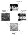
- FIGS. 6-7illustrate exemplary lighting effects that simulates the adaptation of eyes to changes in lighting conditions.
- FIG. 8illustrates exemplary changes in viewing field of view with no lighting effects.
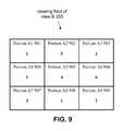
- FIG. 9illustrates exemplary portions within a viewing field of view.
- FIG. 1illustrates system 10 for simulating the adaptation of eyes to changes in lighting conditions.
- System 10may include one or more of processor 11 , display 12 , electronic storage 13 , interface 14 (e.g., bus, wireless interface), and/or other components.
- Visual information defining visual contentmay be accessed by processor 11 .
- the visual contentincluding one or more views of real world scenes, may have been captured by one or more image sensors.
- the capture of visual content by image sensor(s)may define a luminance of the visual content.
- a viewing field of viewmay define an extent of the visual content presented on a display.
- the luminancemay vary as a function of a viewing field of view.
- a usermay change the viewing field of view from a first viewing field of view to a second viewing field.
- a first luminance of the visual content within the first viewing field of view and a second luminance of the visual content within the second viewing field of viewmay be determined.
- a lighting effectmay be applied to the visual content based on a difference between the first luminance and the second luminance.
- the lighting effectmay simulate the adaptation of eyes to a change in lighting conditions between the visual content within the first viewing field of view and the visual content within the second viewing field of view.
- Visual contentmay refer to media content that may be observed visually.
- the visual contentmay include one or more views of one or more real world scenes.
- Visual contentmay have been captured by one or more image sensors.
- Visual contentmay have been captured at a time or at different times.
- Visual contentmay have been captured at one or more real world locations.
- Visual contentmay include one or more of an image, a sequence of images, a frame of a video, a video, and/or other visual content.
- the capture of the visual content by the image sensor(s)may define a luminance of the visual content.
- Luminancemay measure luminous intensities of a real world scene captured within visual content by one or more image sensors.
- Luminancemay indicate brightness of a real world scene captured within the visual content.
- Luminancemay describe perceived brightness of one or more colors captured within the visual content.
- Visual content/a portion of visual content having higher luminancemay appear to be brighter than another visual content/another portion of the visual content having lower luminance.
- visual contentmay include spherical visual content.
- FIG. 3Aillustrates an exemplary spherical visual content 300 .
- Spherical visual content 300may include visual content obtained by a spherical capture.
- Spherical visual content 300may include 360 degrees or less than 360 degrees capture of visual content at one or more locations.
- Spherical visual content 300may include views of real world scenes from one or more locations at one or more times.
- spherical visual content 300may include views of one or more real world scenes located inside a building at a particular time or particular times. Visual content including other views of other real world scenes are contemplated.
- Display 12may include one or more devices that visually presents information.
- the displaymay include one or more of a head-mounted display, a see-through display, a visor, eyeglasses, sunglasses, a smartphone, a tablet, a mobile device, a monitor, a projector, and/or other displays.
- Display 12may be configured to present visual content within a viewing field of view.
- a viewing field of viewmay define an extent of the visual content presented on display 12 .
- FIG. 3Billustrates exemplary viewing field of view A 350 and viewing field of view B 355 for spherical visual content 300 .
- Viewing field of view A 350may be smaller than viewing field of view B 355 .
- Presentation of spherical visual content 300 within viewing field of view A 350 on display 12may include a smaller portion of spherical visual content 300 than presentation of spherical visual content 300 within viewing field of view B 355 on display 12 .
- the luminance of the visual contentmay vary as a function of the viewing field of view.
- FIG. 4illustrates exemplary directions for different fields of view.
- Spherical visual content 300 within a viewing field of view directed in forward direction 410aligned with positive roll axis 300
- FIGS. 5A-5Cillustrates exemplary views within spherical visual content 300 .
- Forward view 510may include spherical visual content 300 within a viewing field of view directed in forward direction 410 .
- Left view 520may include spherical visual content 300 within a viewing field of view directed in left direction 420 .
- Down view 530may include spherical visual content 300 within a viewing field of view directed in down direction 430 .
- Luminance of forward view 510may be higher than luminance of left view 520 and luminance of down view 530 .
- Luminance of down view 530may be higher than luminance of left view 520 .
- Electronic storage 13may be configured to include electronic storage medium that electronically stores information.
- Electronic storage 13may store software algorithms, information determined by processor 11 , information received remotely, and/or other information that enables system 10 to function properly.
- electronic storage 13may store information relating to visual content, luminance of the visual content, viewing fields of view, lighting effects, and/or other information.
- Processor 11may be configured to provide information processing capabilities in system 10 .
- processor 11may comprise one or more of a digital processor, an analog processor, a digital circuit designed to process information, a central processing unit, a graphics processing unit, a microcontroller, an analog circuit designed to process information, a state machine, and/or other mechanisms for electronically processing information.
- Processor 11may be configured to execute one or more machine readable instructions 100 to facilitate simulating the adaptation of eyes to changes in lighting conditions.
- Machine readable instructions 100may include one or more computer program components.
- Machine readable instructions 100may include one or more of visual information component 102 , display component 104 , user input component 106 , luminance component 108 , lighting effect component 110 , and/or other computer program components.
- Visual information component 102may be configured to access visual information.
- the visual informationmay define one or more visual content.
- Visual information component 102may access one or more visual information from one or more storage locations.
- a storage locationmay include electronic storage 13 , electronic storage of one or more image sensors (not shown in FIG. 1 ), and/or other locations.
- Visual information component 102may be configured to access visual information defining one or more visual content during acquisition of the visual information and/or after acquisition of the visual information by one or more image sensors.
- visual information component 102may access visual information defining a video while the video is being captured by one or more image sensors.
- Visual information component 102may access visual information defining a video after the video has been captured and stored in memory (e.g., electronic storage 13 ).
- Display component 104may be configured to present the visual content on display 12 .
- the extent of the visual content presented on display 12may be defined by a viewing field of view and/or other information.
- display component 104may present forward view 510 on display 12 based on a user having selected a viewing field of view directed in forward direction 410 .
- Display component 104may present left view 520 on display 12 based on a user having selected a viewing field of view directed in left direction 420 .
- Display component 104may present down view 530 on display 12 based on a user having selected a viewing field of view directed in down direction 430 .
- Other presentation of the visual content on display 12are contemplated.
- display component 104may present the visual content through a user interface of a visual application.
- a visual applicationmay refer to one or more software, one or more software running on one or more hardware (e.g., a mobile device, a desktop device, a camera), and/or other applications operating to present visual content on display 12 .
- a visual applicationmay include one or more of visual content viewer, visual content editor, and/or other visual application.
- a user interfacemay refer to a graphical user interface that allows a user to interact with the visual application.
- the user interfacemay appear upon interaction with the visual application by the user.
- the user interfacemay disappear if there is no interaction with the visual application over a duration of time.
- the graphical user interfacemay include one or more buttons/selections (e.g., rewind button, pause button, play button, fast-forward button, zoom button, swivel button) for controlling the presentation of the visual content on display 12 .
- User input component 106may be configured to receive user input.
- the user inputmay indicate a user's selections of the viewing field of view and/or other information.
- the user's selections of the viewing field of viewmay include one or more selections of the viewing field of view at different times. For example, a user may initially select a viewing field of view directed in forward direction 410 . The user may later change the selection of the viewing field of view to a viewing field of view directed in left direction 420 . Other selections of the viewing field of view and changes in selections of viewing field of view are contemplated.
- user input component 106may receive user input based on movements of a user's head (e.g., a user is using a head-mounted display and can change the selection of the viewing field of view by moving/rotating the head). In some implementations, user input component 106 may receive user input based on a user's interaction with buttons (e.g., keyboard, virtual buttons), mouse, touchscreen display, joystick, and/or other user-input devices.
- buttonse.g., keyboard, virtual buttons
- mousetouchscreen display
- joystickand/or other user-input devices.
- Luminance component 108may be configured to determine the luminance of the visual content within one or more viewing fields of view. For example, luminance component 108 may determine luminance of forward view 510 , left view 520 , down view 530 , and/or other views of spherical visual content 300 . Luminance may vary within the visual content. For example, luminance of forward view 510 may be higher than luminance of left view 520 and luminance of down view 530 . Luminance of down view 530 may be higher than luminance of left view 520 .
- Luminance of the visual contentmay be defined by the capture of the visual content by one or more image sensor(s).
- Luminance determined by luminance component 108may refer to actual luminance of the visual content or other metric that is related to or derived at least in part from the actual luminance of the visual content.
- Luminance component 108may determine luminance of the visual content based on analysis of the visual content, analysis of information regarding capture of the visual content, and/or other information. For example, luminance component 108 may determine the luminance of visual content within different viewing fields of view based on analysis of the extent of the visual content presented on display 12 (e.g., forward view 510 , left view 520 , down view 530 ), and/or other information.
- Luminance component 108may determine the luminance of visual content within different viewing fields of view based on analysis of information regarding capture of the visual content (e.g., exposure triangle setting of the image sensor(s) for the relevant field of view at the time of capture, exposure meter/light metering for the relevant field of view at the time of capture, exposure compensation for the relevant field of view at the time of capture) that indicates luminance of the extent of the visual content presented on display 12 .
- Luminance component 108may determine the luminance of visual content within different viewing fields of view based on analysis of the extent of the visual content presented on display 12 and information regarding capture of the visual content that indicates luminance of the extent of the visual content presented on display 12 , Other methods of determining luminance of the visual content within different fields of view are contemplated.
- Luminance of the visual contentmay not be defined by generation of virtual visual content.
- Virtual visual contentmay refer to visual content generated by a computer and including a view of a virtual world scene.
- a graphics engine running on a computermay generate virtual visual content including a view of a virtual world scene.
- Luminance of the virtual visual content within a viewing field of viewmay be determine based on the generation of the virtual visual content by the graphic engine.
- Luminance component 108may not determine the luminance of the visual content within one or more viewing fields of view based on the generation of virtual visual content by a computer.
- a viewing field of viewmay include multiple portions.
- viewing field of view B 355may include portion A 1 901 , portion A 2 902 , portion A 3 903 , portion A 4 904 , portion A 5 905 , portion A 6 906 , portion A 7 907 , portion A 8 908 , portion A 9 909 , and/or other portions.
- Values within different portions 901 - 909may represent amount of luminance within the different portions.
- One or more portions 901 - 909 of viewing field of view B 355may be weighed differently from other portions for the determination of luminance of visual content within viewing field of view B 355 .
- portion A 5 905may include a center portion of viewing field of view B 355 and portion A 6 may include a side portion of viewing field of view B 355 .
- Portion A 5 905may have a greater impact on the determination of luminance of visual content within viewing field of view B 355 than portion A 6 906 .
- luminance of portion A 5 905may be characterized with value “4” and luminance of portion A 6 906 may be characterized with value “6.”
- Value “4” of portion A 5 905may have a greater impact on the determination of luminance of visual content within viewing field of view B 355 than value “6” of portion A 6 906 .
- luminance component 108may prioritize different portions of a viewing field of view for luminance determination. For example, luminance component 108 may prioritize a center portion of a viewing field of view over other portions of a viewing field of view for luminance determination. Other prioritizations of portions of a viewing field of view for luminance determination are contemplated.
- one or more parts of viewing field of viewmay be weighed based on the portion(s) of the color spectrum present in the portions. For example, in high light conditions, human eyes may be more sensitive to yellow than blue. Yellow light may be perceived to be brighter than blue light of equal intensity. For visual content of high light conditions, luminance component 108 may weigh parts containing the color spectrum corresponding to yellow more than parts containing the color spectrum corresponding to blue for luminance determination. In some implementations, luminance component 108 may determine luminance based on one or more color spectrums (e.g., yellow in high light conditions) and may disregard one or more other color spectrums (e.g., blue in high light conditions) based on sensitivity of human eyes to different color spectrums.
- one or more color spectrumse.g., yellow in high light conditions
- other color spectrumse.g., blue in high light conditions
- luminance component 108may prioritize a portion of a viewing field of view based on a gaze of a user. For example, luminance component 108 may determine that within viewing field of view B 355 , a user's eyes are focused on portion A 9 909 . In response, portion A 9 909 may have a greater impact on the determination of luminance of visual content within viewing field of view B 355 than other portions. Weighing a portion of the viewing field of view based on a gaze of a user may allow for luminance component 108 to determine luminance such that the triggering of the lighting effect is based on the gaze of the user on the visual content.
- Lighting effect component 110may be configured to apply one or more lighting effects to the visual content.
- a lighting effectmay simulate the adaptation of eyes to a change in lighting conditions between the visual content within different viewing fields of view.
- a lighting effectmay simulate the adaptation of eyes to a change in lighting conditions between the visual content within a first viewing field of view selected by a user and a second viewing field of view selected by the user.
- the lighting effectmay simulate the visual content within the second viewing field of view being overexposed based on the luminance of the visual content within the second viewing field of view being higher than the luminance of the visual content within the first viewing field of view.
- Simulating overexposure of the visual contentmay simulate adaptation of eyes to lighting conditions changing from a darker lighting condition to a brighter lighting condition.
- Simulating overexposure of the visual content within a viewing field of viewmay increase the brightness of one or more portions of the visual content within the viewing field of view and may reduce the amount of details (e.g., highlight detail) of the visual content within the viewing field of view.
- FIGS. 6-7illustrate exemplary lighting effects that simulate the adaptation of eyes to changes in lighting conditions.
- luminance of forward view 510may be higher than luminance of left view 520 .
- a usermay change the viewing field of view to change the visual content presented on display 12 from left view 520 to forward view 510 .
- lighting effect component 110may apply a lighting effect that simulates the forward view 510 being overexposed.
- the lighting effectmay cause display 12 to present brighter forward view A 610 .
- Display 12may present brighter forward view A 610 for a duration before displaying forward view 510 .
- the lighting effectmay change over time so that display 12 initially presents brighter forward view A 610 and gradually changes to present forward view 510 .
- the lighting effectmay simulate the visual content within the second viewing field of view being underexposed based on the luminance of the visual content within the second viewing field of view being lower than the luminance of the visual content within the first viewing field of view.
- Simulating underexposure of the visual contentmay simulate adaptation of eyes to lighting conditions changing from a brighter lighting condition to a darker lighting condition.
- Simulating underexposure of the visual content within a viewing field of viewmay decrease the brightness of one or more portions of the visual content within the viewing field of view and may reduce the amount of details (e.g., shadow detail) of the visual content within the viewing field of view.
- luminance of left view 520may be lower than luminance of forward view 510 .
- a usermay change the viewing field of view to change the visual content presented on display 12 from forward view 510 to left view 520 .
- lighting effect component 110may apply a lighting effect that simulates the left view 520 being underexposed.
- the lighting effectmay cause display 12 to present darker left view 620 .
- Display 12may present darker left view 620 for a duration before displaying left view 520 .
- the lighting effectmay change over time so that display 12 initially presents darker left view 620 and gradually changes to present left view 520 .
- the lighting effectmay change a brightness of the visual content within the second viewing field of view based on the difference between the luminance of the visual content within the first viewing field of view and the luminance of the visual content within the second viewing field of view.
- the lighting effectmay increase the brightness of one or more portions of the visual content within the second viewing field of view based on the luminance of the visual content within the second viewing field of view being higher than the luminance of the visual content within the first viewing field of view.
- the lighting effectmay decrease the brightness of one or more portions of the visual content within the second viewing field of view based on the luminance of the visual content within the second viewing field of view being lower than the luminance of the visual content within the first viewing field of view.
- the visual content within a viewing field of viewmay include different portions.
- the change(s) in the brightness of the visual content within a viewing field of viewmay include different amounts of changes in the brightness in the different portions based on the luminance within the different portions.
- the brighter portions within the visual content within the viewing field of viewmay be brightened more than the darker portions within the visual content.
- the darker portions within the visual content within the viewing field of viewmay be darkened more than the brighter portions within the visual content.
- the lighting effectmay change one or more tonal ranges of the visual content within a viewing field of view. Changing the width and/or location of tonal ranges may change the contrast of highlight and/or shadow areas of visual content within a viewing field of view. For example, reducing the width of the tonal range may reduce the contrast of the visual content within the viewing field of view. Increasing the width of the tonal range may increase the contrast of the visual content within the viewing field of view. Changing the contrast of the visual content within a viewing field of view may change the amount of details of the visual content within the viewing field of view. The lighting effect may change the tonal range of the visual content within the viewing field of view to change the amount of details of the visual content within the viewing field of view. Other changes of visual content within a viewing field of view are contemplated.
- the lighting effects to be appliedmay be determined based on a difference between the luminance of the first viewing field of view selected by a user and the luminance of the second viewing field of view selected by the user, and/or other information.
- the differences between two or more luminancemay include one or more differences in a median of the luminance, a mean of the luminance, a range of the luminance, a maximum of the luminance, and/or other differences between the luminance.
- the amount of lighting effect(e.g., the degree to which the lighting effect changes the brightness, exposure, tonal ranges of the visual content) may be determined based on the amount of difference between the luminance of visual content within different viewing fields of view. For example, larger differences between the luminance of visual content within different viewing fields of view may lead to larger amounts of lighting effect (e.g., larger changes in brightness, exposure, tonal ranges of the visual content) and smaller differences between the luminance of visual content within different viewing fields of view may lead to smaller amounts of lighting effect (e.g., smaller changes in brightness, exposure, tonal ranges of the visual content).
- larger differences between the luminance of visual content within different viewing fields of viewmay lead to larger amounts of lighting effect (e.g., larger changes in brightness, exposure, tonal ranges of the visual content) and smaller differences between the luminance of visual content within different viewing fields of view may lead to smaller amounts of lighting effect (e.g., smaller changes in brightness, exposure, tonal ranges of the visual content).
- a usermay change the viewing field of view to change the visual content presented on display 12 from down view 530 to forward view 510 .
- lighting effect component 110may apply a lighting effect that simulates the forward view 510 being overexposed.
- the lighting effectmay cause display 12 to present brighter forward view B 615 .
- Display 12may present brighter forward view B 615 for a duration before displaying forward view 510 .
- the lighting effectmay change over time so that display 12 initially presents brighter forward view B 615 and gradually changes to presenting forward view 510 .
- Luminance of down view 530may be higher than luminance of left view 520 (shown in FIG. 6 ).
- the difference between the luminance of forward view 510 and down view 530may be smaller than the difference between the luminance of forward view 510 and left view 520 .
- the amount of lighting effect applied by lighting effect component 110 when a user changes the viewing field of view to change the visual content presented on display 12 from down view 530 to forward view 510may be smaller than the amount of lighting effect applied by lighting effect component 110 when a user changes the viewing field of view to change the visual content presented on display 12 from left view 520 to forward view 510 .
- brighter forward view B 615may not be as bright as brighter forward view A 610 .
- the lighting effectmay be applied to the visual content for one or more time durations based on the difference between the luminance of visual content within different viewing fields of view, and/or other information. For example, larger differences between the luminance of visual content within different viewing fields of view may lead to the lighting effect being applied for a longer duration and smaller differences between the luminance of visual content within different viewing fields of view may lead to the lighting effect being applied for a shorter duration.
- the effect of the lighting effect on the visual contentmay gradually change over the effective time duration.
- the lighting effectmay be applied to the visual content based on the difference between the luminance of the first viewing field of view selected by a user and the luminance of the second viewing field of view selected by the user meeting or exceeding a threshold. Small differences between the luminance of different viewing fields of view that does not meet the threshold may not trigger a lighting effect. For example, as shown in FIG. 8 , the luminance of left view 520 and the luminance of down view 530 may not be large enough to trigger the application of lighting effect by lighting effect component 110 . A user changing the viewing field of view to change the presentation of visual content presented on display 12 from left view 520 to down view 530 , or vice versa, may not see the lighting effect.
- No intermediate views of left view 520 or down view 530may be presented on display 12 when the user changes the viewing field of view between left view 520 and down view 530 .
- Implementations of the disclosuremay be made in hardware, firmware, software, or any suitable combination thereof. Aspects of the disclosure may be implemented as instructions stored on a machine-readable medium, which may be read and executed by one or more processors.
- a machine-readable mediummay include any mechanism for storing or transmitting information in a form readable by a machine (e.g., a computing device).
- a tangible computer readable storage mediummay include read only memory, random access memory, magnetic disk storage media, optical storage media, flash memory devices, and others
- a machine-readable transmission mediamay include forms of propagated signals, such as carrier waves, infrared signals, digital signals, and others.
- Firmware, software, routines, or instructionsmay be described herein in terms of specific exemplary aspects and implementations of the disclosure, and performing certain actions.
- processor 11may communicate with each other through hard-wired communication, wireless communication, or both.
- one or more components of system 10may communicate with each other through a network.
- processor 11may wirelessly communicate with electronic storage 13 .
- wireless communicationmay include one or more of radio communication, Bluetooth communication, Wi-Fi communication, cellular communication, infrared communication, or other wireless communication. Other types of communications are contemplated by the present disclosure.
- processor 11may comprise a plurality of processing units. These processing units may be physically located within the same device, or processor 11 may represent processing functionality of a plurality of devices operating in coordination. Processor 11 may be configured to execute one or more components by software; hardware; firmware; some combination of software, hardware, and/or firmware; and/or other mechanisms for configuring processing capabilities on processor 11 .
- FIG. 1it should be appreciated that although computer components are illustrated in FIG. 1 as being co-located within a single processing unit, in implementations in which processor 11 comprises multiple processing units, one or more of computer program components may be located remotely from the other computer program components.
- processor 11may be configured to execute one or more additional computer program components that may perform some or all of the functionality attributed to one or more of computer program components 102 , 104 , 106 , 108 , and/or 110 described herein.
- the electronic storage media of electronic storage 13may be provided integrally (i.e., substantially non-removable) with one or more components of system 10 and/or removable storage that is connectable to one or more components of system 10 via, for example, a port (e.g., a USB port, a Firewire port, etc.) or a drive (e.g., a disk drive, etc.).
- a porte.g., a USB port, a Firewire port, etc.
- a drivee.g., a disk drive, etc.
- Electronic storage 13may include one or more of optically readable storage media (e.g., optical disks, etc.), magnetically readable storage media (e.g., magnetic tape, magnetic hard drive, floppy drive, etc.), electrical charge-based storage media (e.g., EPROM, EEPROM, RAM, etc.), solid-state storage media (e.g., flash drive, etc.), and/or other electronically readable storage media.
- Electronic storage 13may be a separate component within system 10 , or electronic storage 13 may be provided integrally with one or more other components of system 10 (e.g., processor 11 ). Although electronic storage 13 is shown in FIG. 1 as a single entity, this is for illustrative purposes only. In some implementations, electronic storage 13 may comprise a plurality of storage units. These storage units may be physically located within the same device, or electronic storage 13 may represent storage functionality of a plurality of devices operating in coordination.
- FIG. 2illustrates method 200 for simulating adaptation of eyes to changes in lighting conditions.
- the operations of method 200 presented beloware intended to be illustrative. In some implementations, method 200 may be accomplished with one or more additional operations not described, and/or without one or more of the operations discussed. In some implementations, two or more of the operations may occur substantially simultaneously.
- method 200may be implemented in one or more processing devices (e.g., a digital processor, an analog processor, a digital circuit designed to process information, a central processing unit, a graphics processing unit, a microcontroller, an analog circuit designed to process information, a state machine, and/or other mechanisms for electronically processing information).
- the one or more processing devicesmay include one or more devices executing some or all of the operation of method 200 in response to instructions stored electronically on one or more electronic storage mediums.
- the one or more processing devicesmay include one or more devices configured through hardware, firmware, and/or software to be specifically designed for execution of one or more of the operation of method 200 .
- visual information defining visual contentmay be accessed.
- the visual contentmay have been captured by one or more image sensors and may include one or more views of one or more real world scenes.
- the capture of the visual content by the image sensor(s)may define a luminance of the visual content.
- the luminancemay vary as a function of a viewing field of view.
- the viewing field of viewmay define an extent of the visual content presented on a display.
- operation 201may be performed by a processor component the same as or similar to visual information component 102 (Shown in FIG. 1 and described herein).
- operation 202the visual content within a viewing field of view may be presented on a display.
- operation 202may be performed by a processor component the same as or similar to display component 104 (Shown in FIG. 1 and described herein).
- operation 203user input indicating a user's selections of the viewing field of view may be received.
- the user's selections of the viewing field of viewmay include a first selection of a first viewing field of view at a first time, and a second selection of a second viewing field of view at a second time.
- the second timemay be subsequent to the first time.
- operation 203may be performed by a processor component the same as or similar to user input component 106 (Shown in FIG. 1 and described herein).
- a first luminance of the visual content within the first viewing field of view and a second luminance of the visual content within the second viewing field of viewmay be determined.
- operation 204may be performed by a processor component the same as or similar to luminance component 108 (Shown in FIG. 1 and described herein).
- a lighting effectmay be applied based on a difference between the first luminance and the second luminance.
- the lighting effectmay simulate the adaptation of eyes to a change in lighting conditions between the visual content within the first viewing field of view and the visual content within the second viewing field of view.
- operation 205may be performed by a processor component the same as or similar to lighting effect component 110 (Shown in FIG. 1 and described herein).
Landscapes
- Engineering & Computer Science (AREA)
- Theoretical Computer Science (AREA)
- Physics & Mathematics (AREA)
- General Physics & Mathematics (AREA)
- Computer Hardware Design (AREA)
- Human Computer Interaction (AREA)
- General Engineering & Computer Science (AREA)
- Controls And Circuits For Display Device (AREA)
- User Interface Of Digital Computer (AREA)
Abstract
Description
Claims (20)
Priority Applications (2)
| Application Number | Priority Date | Filing Date | Title |
|---|---|---|---|
| US15/271,931US9934758B1 (en) | 2016-09-21 | 2016-09-21 | Systems and methods for simulating adaptation of eyes to changes in lighting conditions |
| US15/943,006US10546555B2 (en) | 2016-09-21 | 2018-04-02 | Systems and methods for simulating adaptation of eyes to changes in lighting conditions |
Applications Claiming Priority (1)
| Application Number | Priority Date | Filing Date | Title |
|---|---|---|---|
| US15/271,931US9934758B1 (en) | 2016-09-21 | 2016-09-21 | Systems and methods for simulating adaptation of eyes to changes in lighting conditions |
Related Child Applications (1)
| Application Number | Title | Priority Date | Filing Date |
|---|---|---|---|
| US15/943,006ContinuationUS10546555B2 (en) | 2016-09-21 | 2018-04-02 | Systems and methods for simulating adaptation of eyes to changes in lighting conditions |
Publications (1)
| Publication Number | Publication Date |
|---|---|
| US9934758B1true US9934758B1 (en) | 2018-04-03 |
Family
ID=61711516
Family Applications (2)
| Application Number | Title | Priority Date | Filing Date |
|---|---|---|---|
| US15/271,931Active2036-11-05US9934758B1 (en) | 2016-09-21 | 2016-09-21 | Systems and methods for simulating adaptation of eyes to changes in lighting conditions |
| US15/943,006ActiveUS10546555B2 (en) | 2016-09-21 | 2018-04-02 | Systems and methods for simulating adaptation of eyes to changes in lighting conditions |
Family Applications After (1)
| Application Number | Title | Priority Date | Filing Date |
|---|---|---|---|
| US15/943,006ActiveUS10546555B2 (en) | 2016-09-21 | 2018-04-02 | Systems and methods for simulating adaptation of eyes to changes in lighting conditions |
Country Status (1)
| Country | Link |
|---|---|
| US (2) | US9934758B1 (en) |
Cited By (1)
| Publication number | Priority date | Publication date | Assignee | Title |
|---|---|---|---|---|
| US12394344B1 (en)* | 2021-10-20 | 2025-08-19 | Axon Enterprise, Inc. | Adaptive brightness display for recording device |
Citations (115)
| Publication number | Priority date | Publication date | Assignee | Title |
|---|---|---|---|---|
| US5260779A (en) | 1992-02-21 | 1993-11-09 | Control Automation, Inc. | Method and apparatus for inspecting a printed circuit board |
| EP0605045A1 (en) | 1992-12-29 | 1994-07-06 | Laboratoires D'electronique Philips S.A.S. | Image processing method and apparatus for generating one image from adjacent images |
| EP0650299A1 (en) | 1993-10-20 | 1995-04-26 | Laboratoires D'electronique Philips S.A.S. | Image processing system comprising fixed cameras and a system simulating a moving camera |
| EP0661672A1 (en) | 1993-12-29 | 1995-07-05 | Laboratoires D'electronique Philips S.A.S. | Picture processing process and device for building a target image from a source image with perspective change |
| US5555895A (en) | 1993-01-29 | 1996-09-17 | Centre National De La Recherche Scientifique | Process and device for eye movement analysis |
| US6434265B1 (en) | 1998-09-25 | 2002-08-13 | Apple Computers, Inc. | Aligning rectilinear images in 3D through projective registration and calibration |
| US20020112005A1 (en) | 1998-08-25 | 2002-08-15 | Charles Namias | Video e-mail kiosk |
| US20020122113A1 (en) | 1999-08-09 | 2002-09-05 | Foote Jonathan T. | Method and system for compensating for parallax in multiple camera systems |
| US6486908B1 (en) | 1998-05-27 | 2002-11-26 | Industrial Technology Research Institute | Image-based method and system for building spherical panoramas |
| US20020191087A1 (en) | 1996-04-15 | 2002-12-19 | Canon Kabushiki Kaisha | Communication apparatus and method that link a network address with designated image information |
| US20030085992A1 (en) | 2000-03-07 | 2003-05-08 | Sarnoff Corporation | Method and apparatus for providing immersive surveillance |
| US20030098954A1 (en) | 2001-04-27 | 2003-05-29 | International Business Machines Corporation | Calibration-free eye gaze tracking |
| US20030160862A1 (en) | 2002-02-27 | 2003-08-28 | Charlier Michael L. | Apparatus having cooperating wide-angle digital camera system and microphone array |
| US20040010804A1 (en) | 1996-09-04 | 2004-01-15 | Hendricks John S. | Apparatus for video access and control over computer network, including image correction |
| US20040021780A1 (en) | 2002-07-31 | 2004-02-05 | Intel Corporation | Method and apparatus for automatic photograph annotation with contents of a camera's field of view |
| US20040047606A1 (en) | 2002-09-09 | 2004-03-11 | Canon Kabushiki Kaisha | Image recording apparatus capable of recording information associated with location upon image sensing together with sensed image data, and control method thereof |
| US6711293B1 (en) | 1999-03-08 | 2004-03-23 | The University Of British Columbia | Method and apparatus for identifying scale invariant features in an image and use of same for locating an object in an image |
| US6710740B2 (en) | 2002-03-04 | 2004-03-23 | Intel Corporation | Recording-location determination |
| US20040075738A1 (en) | 1999-05-12 | 2004-04-22 | Sean Burke | Spherical surveillance system architecture |
| US20040135900A1 (en) | 2003-01-15 | 2004-07-15 | Hewlett Packard Company | Method and apparatus for capture of sensory data in association with image data |
| US20040169724A1 (en) | 2002-12-09 | 2004-09-02 | Ekpar Frank Edughom | Method and apparatus for creating interactive virtual tours |
| US6788333B1 (en) | 2000-07-07 | 2004-09-07 | Microsoft Corporation | Panoramic video |
| US20050033760A1 (en) | 1998-09-01 | 2005-02-10 | Charles Fuller | Embedded metadata engines in digital capture devices |
| US20050062869A1 (en) | 1999-04-08 | 2005-03-24 | Zimmermann Steven Dwain | Immersive video presentations |
| US20050104976A1 (en) | 2003-11-17 | 2005-05-19 | Kevin Currans | System and method for applying inference information to digital camera metadata to identify digital picture content |
| US20050134707A1 (en) | 2003-12-18 | 2005-06-23 | Eastman Kodak Company | Image metadata attachment |
| US20050289111A1 (en) | 2004-06-25 | 2005-12-29 | Tribble Guy L | Method and apparatus for processing metadata |
| US20060050997A1 (en) | 2004-09-09 | 2006-03-09 | Casio Computer Co., Ltd. | Camera device with movie capture function |
| US7057663B1 (en) | 2001-05-17 | 2006-06-06 | Be Here Corporation | Audio synchronization pulse for multi-camera capture systems |
| US20070030358A1 (en) | 2005-07-19 | 2007-02-08 | Canon Kabushiki Kaisha | Image-processing device, method for controlling same, computer program, and storage medium |
| US20070053659A1 (en) | 2003-10-10 | 2007-03-08 | Jiro Kiyama | Reproducing apparatus, method for controlling reproducing apparatus, content recording medium, data structure, control program, computer-readable recording medium storing control program |
| US20070120986A1 (en) | 2005-11-08 | 2007-05-31 | Takashi Nunomaki | Imaging device, information processing method, and computer program |
| US20070140662A1 (en) | 2005-11-08 | 2007-06-21 | Takashi Nunomaki | Information processing apparatus, imaging device, information processing method, and computer program |
| US20070300249A1 (en) | 2006-06-22 | 2007-12-27 | Smith Kevin P | In-band data recognition and synchronization system |
| US20080094499A1 (en) | 2005-12-07 | 2008-04-24 | Sony Corporation | Imaging apparatus, data recording method and data-display control method, and computer program |
| US20080118100A1 (en) | 2006-11-20 | 2008-05-22 | Canon Kabushiki Kaisha | Information processing apparatus and control method thereof, and computer readable storage medium |
| WO2009047572A1 (en) | 2007-10-09 | 2009-04-16 | Analysis Systems Research High-Tech S.A. | Integrated system, method and application for the synchronized interactive play-back of multiple spherical video content and autonomous product for the interactive play-back of prerecorded events. |
| US20090210707A1 (en) | 2006-05-15 | 2009-08-20 | Paolo De Lutiis | Out-of Band Authentication Method and System for Communication Over a Data Network |
| US20090251558A1 (en) | 2008-04-04 | 2009-10-08 | Samsung Techwin Co., Ltd. | Fast and low-power digital camera with gps |
| US20090262206A1 (en) | 2008-04-16 | 2009-10-22 | Johnson Controls Technology Company | Systems and methods for providing immersive displays of video camera information from a plurality of cameras |
| US20090271447A1 (en) | 2008-04-28 | 2009-10-29 | Shin Kang Soo | Method for synchronizing contents file and device for employing the same |
| US20100045773A1 (en) | 2007-11-06 | 2010-02-25 | Ritchey Kurtis J | Panoramic adapter system and method with spherical field-of-view coverage |
| US20100097443A1 (en) | 2008-10-16 | 2010-04-22 | Peter Lablans | Controller in a Camera for Creating a Panoramic Image |
| US20100238304A1 (en) | 2009-03-18 | 2010-09-23 | Casio Computer Co., Ltd. | Digital camera for recording still image with speech |
| US20100250022A1 (en) | 2006-12-29 | 2010-09-30 | Air Recon, Inc. | Useful unmanned aerial vehicle |
| US20100289924A1 (en) | 2009-05-14 | 2010-11-18 | Hoya Corporation | Imager that adds visual effects to an image |
| US20100299630A1 (en) | 2009-05-22 | 2010-11-25 | Immersive Media Company | Hybrid media viewing application including a region of interest within a wide field of view |
| US20110013778A1 (en) | 2004-06-23 | 2011-01-20 | Yamaha Corporation | Speaker array apparatus and method for setting audio beams of speaker array appratus |
| US20110115883A1 (en) | 2009-11-16 | 2011-05-19 | Marcus Kellerman | Method And System For Adaptive Viewport For A Mobile Device Based On Viewing Angle |
| US20110141300A1 (en) | 2009-12-11 | 2011-06-16 | Fotonation Ireland Limited | Panorama Imaging Using a Blending Map |
| US7983502B2 (en) | 2007-08-06 | 2011-07-19 | Microsoft Corporation | Viewing wide angle images using dynamic tone mapping |
| US20110261227A1 (en) | 2008-09-12 | 2011-10-27 | Nikon Corporation | Imaging apparatus |
| US20120206565A1 (en) | 2011-02-10 | 2012-08-16 | Jason Villmer | Omni-directional camera and related viewing software |
| US20120242798A1 (en) | 2011-01-10 | 2012-09-27 | Terrence Edward Mcardle | System and method for sharing virtual and augmented reality scenes between users and viewers |
| US20130021450A1 (en) | 2011-07-22 | 2013-01-24 | Yasuo Yoshizawa | Stereoscopic imaging system, recording control method, stereoscopic image reproduction system, and reproduction control method |
| US20130058619A1 (en) | 2011-09-02 | 2013-03-07 | Nikon Corporation | Imaging device and image-audio playback device |
| US20130058532A1 (en) | 2007-03-05 | 2013-03-07 | Sportvision, Inc. | Tracking An Object With Multiple Asynchronous Cameras |
| US20130127903A1 (en) | 2009-02-26 | 2013-05-23 | Sylvain Paris | System and Method for Reducing the Appearance of Residuals in Gradient-Based Image Compositing |
| US20130176403A1 (en) | 2011-08-16 | 2013-07-11 | Kenneth Varga | Heads up display (HUD) sensor system |
| US20130177168A1 (en) | 2009-12-24 | 2013-07-11 | Nokia Corporation | Apparatus |
| US20130182177A1 (en) | 2012-01-18 | 2013-07-18 | John Furlan | Systems and methods for improving video stutter in high resolution progressive video |
| US20130210563A1 (en) | 2009-05-02 | 2013-08-15 | Steven J. Hollinger | Ball with camera for reconnaissance or recreation and network for operating the same |
| US20130235226A1 (en) | 2012-03-12 | 2013-09-12 | Keith Stoll Karn | Digital camera having low power capture mode |
| US8606073B2 (en) | 2010-05-12 | 2013-12-10 | Woodman Labs, Inc. | Broadcast management system |
| US20140037268A1 (en) | 2012-08-03 | 2014-02-06 | Canon Kabushiki Kaisha | Moving image recording apparatus capable of recording moving images to recording media, and control method and storage medium therefor |
| US20140039884A1 (en) | 2001-12-14 | 2014-02-06 | Microsoft Corporation | Quality improvement techniques in an audio encoder |
| US8670030B2 (en) | 2010-05-25 | 2014-03-11 | Olympus Imaging Corp. | Photographing device and control method therefor |
| WO2014090277A1 (en) | 2012-12-10 | 2014-06-19 | Nokia Corporation | Spatial audio apparatus |
| US20140240122A1 (en) | 2014-02-27 | 2014-08-28 | Fitbit, Inc. | Notifications on a User Device Based on Activity Detected By an Activity Monitoring Device |
| US8842197B2 (en) | 2005-11-30 | 2014-09-23 | Scenera Mobile Technologies, Llc | Automatic generation of metadata for a digital image based on ambient conditions |
| US8890954B2 (en) | 2010-09-13 | 2014-11-18 | Contour, Llc | Portable digital video camera configured for remote image acquisition control and viewing |
| US20150055937A1 (en) | 2013-08-21 | 2015-02-26 | Jaunt Inc. | Aggregating images and audio data to generate virtual reality content |
| US9019396B2 (en) | 2012-04-19 | 2015-04-28 | Olympus Corporation | Wireless communication device, memory device, wireless communication system, wireless communication method, and program recordable medium |
| US20150142742A1 (en) | 2013-11-17 | 2015-05-21 | Zhen-Chao HONG | System and method for syncing local directories that enable file access across multiple devices |
| US20150142211A1 (en) | 2012-05-04 | 2015-05-21 | Aeryon Labs Inc. | System and method for controlling unmanned aerial vehicles |
| US20150166476A1 (en) | 2013-12-17 | 2015-06-18 | Yi-Cheng Chen | Methods for treating neurodegenerative diseases associated with aggregation of amyloid-beta |
| US20150186073A1 (en) | 2013-12-30 | 2015-07-02 | Lyve Minds, Inc. | Integration of a device with a storage network |
| US20150189221A1 (en) | 2013-12-26 | 2015-07-02 | Canon Kabushiki Kaisha | Image reproducing apparatus and method for controlling same |
| US20150269714A1 (en)* | 2014-03-18 | 2015-09-24 | Thomson Licensing | Method for processing a video sequence, corresponding device, computer program and non-transitory computer-readable-medium |
| US20150287435A1 (en) | 2014-04-04 | 2015-10-08 | Red.Com, Inc. | Video camera with capture modes |
| US20150288754A1 (en) | 2014-04-07 | 2015-10-08 | Palo Alto Research Center Incorporated | Service discovery using collection synchronization with exact names |
| US9158304B2 (en) | 2013-11-10 | 2015-10-13 | Google Inc. | Methods and systems for alerting and aiding an emergency situation |
| US20150304532A1 (en) | 2014-04-18 | 2015-10-22 | Alarm.Com Incorporated | Pan and tilt camera with robotic movement |
| US20150336015A1 (en) | 2014-05-21 | 2015-11-26 | Universal City Studios Llc | Ride vehicle tracking and control system using passive tracking elements |
| US20150350614A1 (en) | 2012-08-31 | 2015-12-03 | Brain Corporation | Apparatus and methods for tracking using aerial video |
| US20150363648A1 (en) | 2014-06-11 | 2015-12-17 | Arris Enterprises, Inc. | Detection of demarcating segments in video |
| US20150370250A1 (en) | 2014-06-19 | 2015-12-24 | Skydio, Inc. | Magic wand interface and other user interaction paradigms for a flying digital assistant |
| US20150367958A1 (en) | 2014-06-20 | 2015-12-24 | nearmap australia pty ltd. | Wide-area aerial camera systems |
| US20160005435A1 (en) | 2014-07-03 | 2016-01-07 | Gopro, Inc. | Automatic generation of video and directional audio from spherical content |
| US20160018822A1 (en) | 2014-07-18 | 2016-01-21 | Helico Aerospace Industries Sia | Autonomous vehicle operation |
| US20160031559A1 (en) | 2014-07-30 | 2016-02-04 | SZ DJI Technology Co., Ltd | Systems and methods for target tracking |
| US20160054737A1 (en) | 2014-08-22 | 2016-02-25 | Cape Productions Inc. | Methods and Apparatus for Unmanned Aerial Vehicle Autonomous Aviation |
| US20160076892A1 (en) | 2014-03-24 | 2016-03-17 | SZ DJI Technology Co., Ltd | Methods and systems for determining a state of an unmanned aerial vehicle |
| US20160098469A1 (en) | 2014-10-07 | 2016-04-07 | Yahoo! Inc. | Method and system for providing a synchronization service |
| US20160101856A1 (en) | 2014-06-23 | 2016-04-14 | Nixie Labs, Inc. | Wearable unmanned aerial vehicles, and associated systems and methods |
| US20160112713A1 (en) | 2014-10-20 | 2016-04-21 | Google Inc. | Mapping spherical image to 2d representations |
| US20160129999A1 (en) | 2014-11-07 | 2016-05-12 | Paccar Inc | Drone systems for pre-trip inspection and assisted backing |
| US20160139596A1 (en) | 2014-11-14 | 2016-05-19 | Lg Electronics Inc. | Mobile terminal and controlling method thereof |
| US20160165563A1 (en) | 2013-07-31 | 2016-06-09 | Samsung Electronics Co., Ltd. | Method and apparatus for time synchronization in device-to-device communication |
| US20160179096A1 (en) | 2014-05-23 | 2016-06-23 | Lily Robotics, Inc. | Launching unmanned aerial copter from mid-air |
| US20160189101A1 (en) | 2014-05-20 | 2016-06-30 | Verizon Patent And Licensing Inc. | Secure payload deliveries via unmanned aerial vehicles |
| US20160234438A1 (en) | 2015-02-06 | 2016-08-11 | Tetsuya Satoh | Image processing system, image generation apparatus, and image generation method |
| US20160239340A1 (en) | 2015-02-13 | 2016-08-18 | International Business Machines Corporation | Determining an ordering to use to open and close programs that call other programs |
| US20160269621A1 (en) | 2015-03-13 | 2016-09-15 | Center For Integrated Smart Sensors Foundation | Front-end event detector and low-power camera system using thereof |
| US20160295108A1 (en) | 2015-04-01 | 2016-10-06 | Cheng Cao | System and method for panoramic imaging |
| US9473758B1 (en) | 2015-12-06 | 2016-10-18 | Sliver VR Technologies, Inc. | Methods and systems for game video recording and virtual reality replay |
| US20160304198A1 (en) | 2014-12-03 | 2016-10-20 | Google Inc. | Systems and methods for reliable relative navigation and autonomous following between unmanned aerial vehicle and a target object |
| US20160306351A1 (en) | 2015-04-14 | 2016-10-20 | Vantage Robotics, Llc | System for authoring, executing, and distributing unmanned aerial vehicle flight-behavior profiles |
| US20160313734A1 (en) | 2015-04-21 | 2016-10-27 | Gopro, Inc. | Return Path Configuration For Remote Controlled Aerial Vehicle |
| US20160327950A1 (en) | 2014-06-19 | 2016-11-10 | Skydio, Inc. | Virtual camera interface and other user interaction paradigms for a flying digital assistant |
| US20160336020A1 (en) | 2015-05-11 | 2016-11-17 | Lily Robotics, Inc. | External microphone for an unmanned aerial vehicle |
| US20160366290A1 (en) | 2015-06-11 | 2016-12-15 | Casio Computer Co., Ltd. | Image shooting apparatus for adding information to image |
| US20170053575A1 (en)* | 2014-02-21 | 2017-02-23 | Sony Corporation | Electronic apparatus and method of providing image |
| US20170061693A1 (en)* | 2015-09-02 | 2017-03-02 | Jeffrey Kohler | Augmented-reality imaging |
| US9602795B1 (en) | 2016-02-22 | 2017-03-21 | Gopro, Inc. | System and method for presenting and viewing a spherical video segment |
- 2016
- 2016-09-21USUS15/271,931patent/US9934758B1/enactiveActive
- 2018
- 2018-04-02USUS15/943,006patent/US10546555B2/enactiveActive
Patent Citations (122)
| Publication number | Priority date | Publication date | Assignee | Title |
|---|---|---|---|---|
| US5260779A (en) | 1992-02-21 | 1993-11-09 | Control Automation, Inc. | Method and apparatus for inspecting a printed circuit board |
| EP0605045A1 (en) | 1992-12-29 | 1994-07-06 | Laboratoires D'electronique Philips S.A.S. | Image processing method and apparatus for generating one image from adjacent images |
| US5555895A (en) | 1993-01-29 | 1996-09-17 | Centre National De La Recherche Scientifique | Process and device for eye movement analysis |
| EP0650299A1 (en) | 1993-10-20 | 1995-04-26 | Laboratoires D'electronique Philips S.A.S. | Image processing system comprising fixed cameras and a system simulating a moving camera |
| EP0661672A1 (en) | 1993-12-29 | 1995-07-05 | Laboratoires D'electronique Philips S.A.S. | Picture processing process and device for building a target image from a source image with perspective change |
| US20020191087A1 (en) | 1996-04-15 | 2002-12-19 | Canon Kabushiki Kaisha | Communication apparatus and method that link a network address with designated image information |
| US20040010804A1 (en) | 1996-09-04 | 2004-01-15 | Hendricks John S. | Apparatus for video access and control over computer network, including image correction |
| US6486908B1 (en) | 1998-05-27 | 2002-11-26 | Industrial Technology Research Institute | Image-based method and system for building spherical panoramas |
| US20020112005A1 (en) | 1998-08-25 | 2002-08-15 | Charles Namias | Video e-mail kiosk |
| US20050033760A1 (en) | 1998-09-01 | 2005-02-10 | Charles Fuller | Embedded metadata engines in digital capture devices |
| US7403224B2 (en) | 1998-09-01 | 2008-07-22 | Virage, Inc. | Embedded metadata engines in digital capture devices |
| US6434265B1 (en) | 1998-09-25 | 2002-08-13 | Apple Computers, Inc. | Aligning rectilinear images in 3D through projective registration and calibration |
| US6711293B1 (en) | 1999-03-08 | 2004-03-23 | The University Of British Columbia | Method and apparatus for identifying scale invariant features in an image and use of same for locating an object in an image |
| US20050062869A1 (en) | 1999-04-08 | 2005-03-24 | Zimmermann Steven Dwain | Immersive video presentations |
| US20040075738A1 (en) | 1999-05-12 | 2004-04-22 | Sean Burke | Spherical surveillance system architecture |
| US20020122113A1 (en) | 1999-08-09 | 2002-09-05 | Foote Jonathan T. | Method and system for compensating for parallax in multiple camera systems |
| US20030085992A1 (en) | 2000-03-07 | 2003-05-08 | Sarnoff Corporation | Method and apparatus for providing immersive surveillance |
| US6788333B1 (en) | 2000-07-07 | 2004-09-07 | Microsoft Corporation | Panoramic video |
| US20030098954A1 (en) | 2001-04-27 | 2003-05-29 | International Business Machines Corporation | Calibration-free eye gaze tracking |
| US7057663B1 (en) | 2001-05-17 | 2006-06-06 | Be Here Corporation | Audio synchronization pulse for multi-camera capture systems |
| US20140039884A1 (en) | 2001-12-14 | 2014-02-06 | Microsoft Corporation | Quality improvement techniques in an audio encoder |
| US20030160862A1 (en) | 2002-02-27 | 2003-08-28 | Charlier Michael L. | Apparatus having cooperating wide-angle digital camera system and microphone array |
| US6710740B2 (en) | 2002-03-04 | 2004-03-23 | Intel Corporation | Recording-location determination |
| US20040021780A1 (en) | 2002-07-31 | 2004-02-05 | Intel Corporation | Method and apparatus for automatic photograph annotation with contents of a camera's field of view |
| US20040047606A1 (en) | 2002-09-09 | 2004-03-11 | Canon Kabushiki Kaisha | Image recording apparatus capable of recording information associated with location upon image sensing together with sensed image data, and control method thereof |
| US20040169724A1 (en) | 2002-12-09 | 2004-09-02 | Ekpar Frank Edughom | Method and apparatus for creating interactive virtual tours |
| US20040135900A1 (en) | 2003-01-15 | 2004-07-15 | Hewlett Packard Company | Method and apparatus for capture of sensory data in association with image data |
| US20070053659A1 (en) | 2003-10-10 | 2007-03-08 | Jiro Kiyama | Reproducing apparatus, method for controlling reproducing apparatus, content recording medium, data structure, control program, computer-readable recording medium storing control program |
| US20050104976A1 (en) | 2003-11-17 | 2005-05-19 | Kevin Currans | System and method for applying inference information to digital camera metadata to identify digital picture content |
| US20050134707A1 (en) | 2003-12-18 | 2005-06-23 | Eastman Kodak Company | Image metadata attachment |
| US20110013778A1 (en) | 2004-06-23 | 2011-01-20 | Yamaha Corporation | Speaker array apparatus and method for setting audio beams of speaker array appratus |
| US20050289111A1 (en) | 2004-06-25 | 2005-12-29 | Tribble Guy L | Method and apparatus for processing metadata |
| US20060050997A1 (en) | 2004-09-09 | 2006-03-09 | Casio Computer Co., Ltd. | Camera device with movie capture function |
| US20070030358A1 (en) | 2005-07-19 | 2007-02-08 | Canon Kabushiki Kaisha | Image-processing device, method for controlling same, computer program, and storage medium |
| US20070120986A1 (en) | 2005-11-08 | 2007-05-31 | Takashi Nunomaki | Imaging device, information processing method, and computer program |
| US20070140662A1 (en) | 2005-11-08 | 2007-06-21 | Takashi Nunomaki | Information processing apparatus, imaging device, information processing method, and computer program |
| US9342534B2 (en) | 2005-11-30 | 2016-05-17 | Scenera Mobile Technologies, Llc | Automatic generation of metadata for a digital image based on meterological conditions |
| US8842197B2 (en) | 2005-11-30 | 2014-09-23 | Scenera Mobile Technologies, Llc | Automatic generation of metadata for a digital image based on ambient conditions |
| US20080094499A1 (en) | 2005-12-07 | 2008-04-24 | Sony Corporation | Imaging apparatus, data recording method and data-display control method, and computer program |
| US20090210707A1 (en) | 2006-05-15 | 2009-08-20 | Paolo De Lutiis | Out-of Band Authentication Method and System for Communication Over a Data Network |
| US20070300249A1 (en) | 2006-06-22 | 2007-12-27 | Smith Kevin P | In-band data recognition and synchronization system |
| US20080118100A1 (en) | 2006-11-20 | 2008-05-22 | Canon Kabushiki Kaisha | Information processing apparatus and control method thereof, and computer readable storage medium |
| US20100250022A1 (en) | 2006-12-29 | 2010-09-30 | Air Recon, Inc. | Useful unmanned aerial vehicle |
| US20130058532A1 (en) | 2007-03-05 | 2013-03-07 | Sportvision, Inc. | Tracking An Object With Multiple Asynchronous Cameras |
| US7983502B2 (en) | 2007-08-06 | 2011-07-19 | Microsoft Corporation | Viewing wide angle images using dynamic tone mapping |
| WO2009047572A1 (en) | 2007-10-09 | 2009-04-16 | Analysis Systems Research High-Tech S.A. | Integrated system, method and application for the synchronized interactive play-back of multiple spherical video content and autonomous product for the interactive play-back of prerecorded events. |
| US20100045773A1 (en) | 2007-11-06 | 2010-02-25 | Ritchey Kurtis J | Panoramic adapter system and method with spherical field-of-view coverage |
| US20090251558A1 (en) | 2008-04-04 | 2009-10-08 | Samsung Techwin Co., Ltd. | Fast and low-power digital camera with gps |
| US20090262206A1 (en) | 2008-04-16 | 2009-10-22 | Johnson Controls Technology Company | Systems and methods for providing immersive displays of video camera information from a plurality of cameras |
| US20090271447A1 (en) | 2008-04-28 | 2009-10-29 | Shin Kang Soo | Method for synchronizing contents file and device for employing the same |
| US20110261227A1 (en) | 2008-09-12 | 2011-10-27 | Nikon Corporation | Imaging apparatus |
| US20100097443A1 (en) | 2008-10-16 | 2010-04-22 | Peter Lablans | Controller in a Camera for Creating a Panoramic Image |
| US20130127903A1 (en) | 2009-02-26 | 2013-05-23 | Sylvain Paris | System and Method for Reducing the Appearance of Residuals in Gradient-Based Image Compositing |
| US20100238304A1 (en) | 2009-03-18 | 2010-09-23 | Casio Computer Co., Ltd. | Digital camera for recording still image with speech |
| US8411166B2 (en) | 2009-03-18 | 2013-04-02 | Casio Computer Co., Ltd. | Digital camera for recording still image with speech |
| US20130210563A1 (en) | 2009-05-02 | 2013-08-15 | Steven J. Hollinger | Ball with camera for reconnaissance or recreation and network for operating the same |
| US20100289924A1 (en) | 2009-05-14 | 2010-11-18 | Hoya Corporation | Imager that adds visual effects to an image |
| US20100299630A1 (en) | 2009-05-22 | 2010-11-25 | Immersive Media Company | Hybrid media viewing application including a region of interest within a wide field of view |
| US20110115883A1 (en) | 2009-11-16 | 2011-05-19 | Marcus Kellerman | Method And System For Adaptive Viewport For A Mobile Device Based On Viewing Angle |
| US20110141300A1 (en) | 2009-12-11 | 2011-06-16 | Fotonation Ireland Limited | Panorama Imaging Using a Blending Map |
| US20130177168A1 (en) | 2009-12-24 | 2013-07-11 | Nokia Corporation | Apparatus |
| US8606073B2 (en) | 2010-05-12 | 2013-12-10 | Woodman Labs, Inc. | Broadcast management system |
| US8670030B2 (en) | 2010-05-25 | 2014-03-11 | Olympus Imaging Corp. | Photographing device and control method therefor |
| US8896694B2 (en) | 2010-09-13 | 2014-11-25 | Contour, Llc | Portable digital video camera configured for remote image acquisition control and viewing |
| US8890954B2 (en) | 2010-09-13 | 2014-11-18 | Contour, Llc | Portable digital video camera configured for remote image acquisition control and viewing |
| US20120242798A1 (en) | 2011-01-10 | 2012-09-27 | Terrence Edward Mcardle | System and method for sharing virtual and augmented reality scenes between users and viewers |
| US20120206565A1 (en) | 2011-02-10 | 2012-08-16 | Jason Villmer | Omni-directional camera and related viewing software |
| US20130021450A1 (en) | 2011-07-22 | 2013-01-24 | Yasuo Yoshizawa | Stereoscopic imaging system, recording control method, stereoscopic image reproduction system, and reproduction control method |
| US20130176403A1 (en) | 2011-08-16 | 2013-07-11 | Kenneth Varga | Heads up display (HUD) sensor system |
| US20130058619A1 (en) | 2011-09-02 | 2013-03-07 | Nikon Corporation | Imaging device and image-audio playback device |
| US20130182177A1 (en) | 2012-01-18 | 2013-07-18 | John Furlan | Systems and methods for improving video stutter in high resolution progressive video |
| US20130235226A1 (en) | 2012-03-12 | 2013-09-12 | Keith Stoll Karn | Digital camera having low power capture mode |
| US9019396B2 (en) | 2012-04-19 | 2015-04-28 | Olympus Corporation | Wireless communication device, memory device, wireless communication system, wireless communication method, and program recordable medium |
| US20150142211A1 (en) | 2012-05-04 | 2015-05-21 | Aeryon Labs Inc. | System and method for controlling unmanned aerial vehicles |
| US20140037268A1 (en) | 2012-08-03 | 2014-02-06 | Canon Kabushiki Kaisha | Moving image recording apparatus capable of recording moving images to recording media, and control method and storage medium therefor |
| US20150350614A1 (en) | 2012-08-31 | 2015-12-03 | Brain Corporation | Apparatus and methods for tracking using aerial video |
| WO2014090277A1 (en) | 2012-12-10 | 2014-06-19 | Nokia Corporation | Spatial audio apparatus |
| US20160165563A1 (en) | 2013-07-31 | 2016-06-09 | Samsung Electronics Co., Ltd. | Method and apparatus for time synchronization in device-to-device communication |
| US20150055937A1 (en) | 2013-08-21 | 2015-02-26 | Jaunt Inc. | Aggregating images and audio data to generate virtual reality content |
| US20150058102A1 (en) | 2013-08-21 | 2015-02-26 | Jaunt Inc. | Generating content for a virtual reality system |
| US9158304B2 (en) | 2013-11-10 | 2015-10-13 | Google Inc. | Methods and systems for alerting and aiding an emergency situation |
| US9409646B2 (en) | 2013-11-10 | 2016-08-09 | Google Inc. | Methods and systems for providing aerial assistance |
| US20150142742A1 (en) | 2013-11-17 | 2015-05-21 | Zhen-Chao HONG | System and method for syncing local directories that enable file access across multiple devices |
| US20150166476A1 (en) | 2013-12-17 | 2015-06-18 | Yi-Cheng Chen | Methods for treating neurodegenerative diseases associated with aggregation of amyloid-beta |
| US20150189221A1 (en) | 2013-12-26 | 2015-07-02 | Canon Kabushiki Kaisha | Image reproducing apparatus and method for controlling same |
| US20150186073A1 (en) | 2013-12-30 | 2015-07-02 | Lyve Minds, Inc. | Integration of a device with a storage network |
| US20170053575A1 (en)* | 2014-02-21 | 2017-02-23 | Sony Corporation | Electronic apparatus and method of providing image |
| US20140240122A1 (en) | 2014-02-27 | 2014-08-28 | Fitbit, Inc. | Notifications on a User Device Based on Activity Detected By an Activity Monitoring Device |
| US20150269714A1 (en)* | 2014-03-18 | 2015-09-24 | Thomson Licensing | Method for processing a video sequence, corresponding device, computer program and non-transitory computer-readable-medium |
| US20160076892A1 (en) | 2014-03-24 | 2016-03-17 | SZ DJI Technology Co., Ltd | Methods and systems for determining a state of an unmanned aerial vehicle |
| US20150287435A1 (en) | 2014-04-04 | 2015-10-08 | Red.Com, Inc. | Video camera with capture modes |
| US20150288754A1 (en) | 2014-04-07 | 2015-10-08 | Palo Alto Research Center Incorporated | Service discovery using collection synchronization with exact names |
| US20150304532A1 (en) | 2014-04-18 | 2015-10-22 | Alarm.Com Incorporated | Pan and tilt camera with robotic movement |
| US20160189101A1 (en) | 2014-05-20 | 2016-06-30 | Verizon Patent And Licensing Inc. | Secure payload deliveries via unmanned aerial vehicles |
| US20150336015A1 (en) | 2014-05-21 | 2015-11-26 | Universal City Studios Llc | Ride vehicle tracking and control system using passive tracking elements |
| US20160179096A1 (en) | 2014-05-23 | 2016-06-23 | Lily Robotics, Inc. | Launching unmanned aerial copter from mid-air |
| US20150363648A1 (en) | 2014-06-11 | 2015-12-17 | Arris Enterprises, Inc. | Detection of demarcating segments in video |
| US20160327950A1 (en) | 2014-06-19 | 2016-11-10 | Skydio, Inc. | Virtual camera interface and other user interaction paradigms for a flying digital assistant |
| US20150370250A1 (en) | 2014-06-19 | 2015-12-24 | Skydio, Inc. | Magic wand interface and other user interaction paradigms for a flying digital assistant |
| US20150367958A1 (en) | 2014-06-20 | 2015-12-24 | nearmap australia pty ltd. | Wide-area aerial camera systems |
| US20160101856A1 (en) | 2014-06-23 | 2016-04-14 | Nixie Labs, Inc. | Wearable unmanned aerial vehicles, and associated systems and methods |
| US20160139602A1 (en) | 2014-06-23 | 2016-05-19 | Nixie Labs, Inc. | Launch-controlled unmanned aerial vehicles, and associated systems and methods |
| US20160005435A1 (en) | 2014-07-03 | 2016-01-07 | Gopro, Inc. | Automatic generation of video and directional audio from spherical content |
| US20160018822A1 (en) | 2014-07-18 | 2016-01-21 | Helico Aerospace Industries Sia | Autonomous vehicle operation |
| US20160031559A1 (en) | 2014-07-30 | 2016-02-04 | SZ DJI Technology Co., Ltd | Systems and methods for target tracking |
| US20160054737A1 (en) | 2014-08-22 | 2016-02-25 | Cape Productions Inc. | Methods and Apparatus for Unmanned Aerial Vehicle Autonomous Aviation |
| US20160098469A1 (en) | 2014-10-07 | 2016-04-07 | Yahoo! Inc. | Method and system for providing a synchronization service |
| US20160112713A1 (en) | 2014-10-20 | 2016-04-21 | Google Inc. | Mapping spherical image to 2d representations |
| US20160129999A1 (en) | 2014-11-07 | 2016-05-12 | Paccar Inc | Drone systems for pre-trip inspection and assisted backing |
| US20160139596A1 (en) | 2014-11-14 | 2016-05-19 | Lg Electronics Inc. | Mobile terminal and controlling method thereof |
| US20160304198A1 (en) | 2014-12-03 | 2016-10-20 | Google Inc. | Systems and methods for reliable relative navigation and autonomous following between unmanned aerial vehicle and a target object |
| US20160234438A1 (en) | 2015-02-06 | 2016-08-11 | Tetsuya Satoh | Image processing system, image generation apparatus, and image generation method |
| US20160239340A1 (en) | 2015-02-13 | 2016-08-18 | International Business Machines Corporation | Determining an ordering to use to open and close programs that call other programs |
| US20160269621A1 (en) | 2015-03-13 | 2016-09-15 | Center For Integrated Smart Sensors Foundation | Front-end event detector and low-power camera system using thereof |
| US20160295108A1 (en) | 2015-04-01 | 2016-10-06 | Cheng Cao | System and method for panoramic imaging |
| US20160306351A1 (en) | 2015-04-14 | 2016-10-20 | Vantage Robotics, Llc | System for authoring, executing, and distributing unmanned aerial vehicle flight-behavior profiles |
| US20160313734A1 (en) | 2015-04-21 | 2016-10-27 | Gopro, Inc. | Return Path Configuration For Remote Controlled Aerial Vehicle |
| US20160336020A1 (en) | 2015-05-11 | 2016-11-17 | Lily Robotics, Inc. | External microphone for an unmanned aerial vehicle |
| US20160366290A1 (en) | 2015-06-11 | 2016-12-15 | Casio Computer Co., Ltd. | Image shooting apparatus for adding information to image |
| US20170061693A1 (en)* | 2015-09-02 | 2017-03-02 | Jeffrey Kohler | Augmented-reality imaging |
| US9473758B1 (en) | 2015-12-06 | 2016-10-18 | Sliver VR Technologies, Inc. | Methods and systems for game video recording and virtual reality replay |
| US9602795B1 (en) | 2016-02-22 | 2017-03-21 | Gopro, Inc. | System and method for presenting and viewing a spherical video segment |
Non-Patent Citations (24)
| Title |
|---|
| "Spatial Audio Lecture Series," Regents of the University of California at Berkeley, Center for New Music and Audio Technologies, 2015, 1 Page, [online] [retrieved on Aug. 20, 2015] Retrieved from the internet <URL:http:I/cnmat.berkelev.edu/spatialaudiolectures>. |
| Benjamin Meyer et al: "Real-time Free-Viewpoint Navigation from Compressed Multi-Video Recordings", Proc. 3D Data Processing, Visualization and Transmission (3DPVT), May 31, 2010 (May 31, 2010), pp. 1-6, XP055091261, Extrait de l'Internet: URL:http://www.cg.cs.tu-bs.de/media/publications/meyer2010realtime.pdf [extrait le Dec. 3, 2013]. |
| Farin et al., "Shortest Circular Paths on Planar Graphs," in 27th Symposium on Information Theory in the Benelux 2006, 8 pgs. |
| Felix Klose et al: "Stereoscopic 3D View Synthesis From Unsynchronized Multi-View Video", Proc. European Signal Processing Conference (EUSIPCO), Barcelona, Spain, Sep. 2, 2011 (Sep. 2, 2011), pp. 1904-1909, XP055091259, Extrait de l'Internet: URL:http://www.cg.cs.tu-bs.de/media/publications/ eusipco2011_3d_synth.pdf [extrait le Dec. 3, 2013]. |
| Foote J et al: 'FlyCam: Practical Panoramic Video and Automatic Camera Control', Multimedia and Expo, 2000. ICME 2000. 2000 IEEE International Conference on New York, NY, USA Jul. 30-Aug. 2, 2000, Piscataway, NJ, USA,IEEE, US, vol. 3, Jul. 30, 2000 (Jul. 30, 2000), pp. 1419-1422, XP010512772, DOI: 10.1109/ICME.2000.871033 ISBN: 978-0-7803-6536-0. |
| FOOTE J., KIMBER D.: "FlyCam: practical panoramic video and automatic camera control", MULTIMEDIA AND EXPO, 2000. ICME 2000. 2000 IEEE INTERNATIONAL CONFEREN CE ON NEW YORK, NY, USA 30 JULY-2 AUG. 2000, PISCATAWAY, NJ, USA,IEEE, US, vol. 3, 30 July 2000 (2000-07-30) - 2 August 2000 (2000-08-02), US, pages 1419 - 1422, XP010512772, ISBN: 978-0-7803-6536-0, DOI: 10.1109/ICME.2000.871033 |
| Hossein Afshari et al: "The Panoptic Camera: A Plenoptic Sensor with Real-Time Omnidirectional Capability", Journal of Signal Processing Systems, vol. 70, No. 3, Mar. 14, 2012 (Mar. 14, 2012), pp. 305-328, XP055092066, ISSN: 1939-8018, DOI: 10.1007/s11265-012-0668-4. |
| HOSSEIN AFSHARI, LAURENT JACQUES, LUIGI BAGNATO, ALEXANDRE SCHMID, PIERRE VANDERGHEYNST, YUSUF LEBLEBICI: "The PANOPTIC Camera: A Plenoptic Sensor with Real-Time Omnidirectional Capability", JOURNAL OF SIGNAL PROCESSING SYSTEMS, vol. 70, no. 3, 1 March 2013 (2013-03-01), pages 305 - 328, XP055092066, ISSN: 19398018, DOI: 10.1007/s11265-012-0668-4 |
| Lipski, C.: "Virtual video camera", SIGGRAPH '09: Posters on, SIGGRAPH '09, vol. 0, Jan. 1, 2009 (Jan 1, 2009), pp. 1-1, XP055091257, New York, New York, USA DOI: 10.1145/1599301.1599394. |
| Mai Zheng et al: "Stitching Video from Webcams", Dec. 1, 2008 (Dec. 1, 2008), Advances in Visual Computing: 4th International Symposium, ISVC 2008, Las Vegas, NV, USA, Dec. 1-3, 2008. Proceedings, Part II, Springer Berlin Heidelberg, Berlin, Heidelberg, pp. 420-429, XP019112243, ISBN: 978-3-540-89645-6 le document en entier. |
| O'Donovan, A., et al., "Audio-Visual Panoramas and Spherical Audio Analysis using the Audio Camera," C1 Proceedings of the 16th International Conference on Auditory Display, Jun. 9-15, 2010, pp. ICAD-167-168, can be retrieved at <URL: https://smartech.gatech.edu/bitstream/handle/1853/49858/0%27DonovanDuraiswami201 O.pdf?sequence=1 >. |
| O'Donovan, A., et al., "Real Time Capture of Audio Images and their Use with Video," 2007 IEEE Workshop on Applications of Signal Processing to Audio and Acoustics, Oct. 21-24, 2007, pp. 10-13. |
| PCT International Search Report and Written Opinion for PCT/US15/38913, Sep. 29, 2015, 15 Pages. |
| PCT International Search Report for PCT/EP2014/057352 dated Jun. 27, 2014, 3 pages. |
| PCT International Search Report for PCT/EP2014/058008 dated May 26, 2014, 3 pages. |
| PCT International Search Report for PCT/EP2014/061897 dated Sep. 15, 2014, 3 pages. |
| Perazzi et al., "Panoramic Video from Unstructured Camera Arrays," Eurographics, vol. 34 (2015), No. 2, 12pgs. |
| Ryan Jackson: ‘Shooting 360-degree video with four GoPro HD Hero cameras / Ryan Jackson Photography’ Feb. 8, 2011 (Feb. 8, 2011), XP055099926, Extrait de l'Internet: URL:http://punkoryan.com/2011/02/08/shooting-360-degree-video-with-four-gopro-hd-hero-cameras [extrait le Feb. 3, 2014] 37 pages. |
| U.S. Appl. No. 14/920,427, filed Oct. 22, 2015, entitled "Apparatus and Methods for Embedding Metadata Into Video Stream" 62 pages. |
| U.S. Appl. No. 14/927,343, filed Oct. 29, 2015, entitled "Apparatus and Methods for Rolling Shutter Compensation for Multi-Camera Systems" 45 pages. |
| U.S. Appl. No. 14/949,786, filed Nov. 23, 2015, entitled "Apparatus and Methods for Image Alignment" 67 pages. |
| U.S. Appl. No. 15/001,038, filed Jan. 19, 2016, entitled "Metadata Capture Apparatus and Methods" 54 pages. |
| WALTER DIDIMO;MAURIZIO PATRIGNANI: "ECCV 2016 conference", vol. 5359, 1 December 2008, SPRINGER INTERNATIONAL PUBLISHING, Cham, ISBN: 978-3-642-38988-7, ISSN: 0302-9743, article MAI ZHENG ; XIAOLIN CHEN ; LI GUO: "Stitching Video from Webcams", pages: 420 - 429, XP019112243, 032548 |
| Zhi et al., "Toward Dynamic Image Mosaic Generation With Robustness to Parallax," IEEE Transactions on Image Processing, vol. 21, No. 1, Jan. 2012, pp. 366-378. |
Cited By (1)
| Publication number | Priority date | Publication date | Assignee | Title |
|---|---|---|---|---|
| US12394344B1 (en)* | 2021-10-20 | 2025-08-19 | Axon Enterprise, Inc. | Adaptive brightness display for recording device |
Also Published As
| Publication number | Publication date |
|---|---|
| US20180226057A1 (en) | 2018-08-09 |
| US10546555B2 (en) | 2020-01-28 |
Similar Documents
| Publication | Publication Date | Title |
|---|---|---|
| US10573085B2 (en) | Reality mixer for mixed reality | |
| KR102340934B1 (en) | Method and device to display background image | |
| EP3419024B1 (en) | Electronic device for providing property information of external light source for interest object | |
| US10475243B2 (en) | Transition between virtual reality and real world | |
| US9844119B2 (en) | Dynamic lighting for head mounted device | |
| US9430038B2 (en) | World-locked display quality feedback | |
| US9551871B2 (en) | Virtual light in augmented reality | |
| US9311751B2 (en) | Display of shadows via see-through display | |
| US10867424B2 (en) | Systems and methods for utilizing a device as a marker for augmented reality content | |
| US9164723B2 (en) | Virtual lens-rendering for augmented reality lens | |
| CN109246463B (en) | Method and device for displaying bullet screen | |
| US20180190019A1 (en) | Augmented reality user interface visibility | |
| KR20160047426A (en) | Controlling brightness of a displayed image | |
| CN113302665A (en) | Illumination estimation for augmented reality | |
| US20180025521A1 (en) | Dynamic modulation for near eye display | |
| KR102399669B1 (en) | Device and method to adjust brightness of display | |
| US9552063B2 (en) | Electronic device including transparent display and method of controlling the electronic device | |
| CN114245907B (en) | Automatic exposure ray tracing | |
| KR102235679B1 (en) | Device and method to display object with visual effect | |
| US10546555B2 (en) | Systems and methods for simulating adaptation of eyes to changes in lighting conditions | |
| EP4521206B1 (en) | Method for rendering virtual object, host, and computer readable storage medium |
Legal Events
| Date | Code | Title | Description |
|---|---|---|---|
| AS | Assignment | Owner name:GOPRO, INC., CALIFORNIA Free format text:ASSIGNMENT OF ASSIGNORS INTEREST;ASSIGNOR:MORAT, JULIEN;REEL/FRAME:039819/0834 Effective date:20160921 | |
| AS | Assignment | Owner name:JPMORGAN CHASE BANK, N.A., AS ADMINISTRATIVE AGENT, NEW YORK Free format text:SECURITY INTEREST;ASSIGNOR:GOPRO, INC.;REEL/FRAME:041777/0440 Effective date:20170123 Owner name:JPMORGAN CHASE BANK, N.A., AS ADMINISTRATIVE AGENT Free format text:SECURITY INTEREST;ASSIGNOR:GOPRO, INC.;REEL/FRAME:041777/0440 Effective date:20170123 | |
| STCF | Information on status: patent grant | Free format text:PATENTED CASE | |
| AS | Assignment | Owner name:JPMORGAN CHASE BANK, N.A., AS ADMINISTRATIVE AGENT, NEW YORK Free format text:SECURITY INTEREST;ASSIGNOR:GOPRO, INC.;REEL/FRAME:047016/0417 Effective date:20180904 Owner name:JPMORGAN CHASE BANK, N.A., AS ADMINISTRATIVE AGENT Free format text:SECURITY INTEREST;ASSIGNOR:GOPRO, INC.;REEL/FRAME:047016/0417 Effective date:20180904 | |
| AS | Assignment | Owner name:GOPRO, INC., CALIFORNIA Free format text:RELEASE OF PATENT SECURITY INTEREST;ASSIGNOR:JPMORGAN CHASE BANK, N.A., AS ADMINISTRATIVE AGENT;REEL/FRAME:055106/0434 Effective date:20210122 | |
| MAFP | Maintenance fee payment | Free format text:PAYMENT OF MAINTENANCE FEE, 4TH YEAR, LARGE ENTITY (ORIGINAL EVENT CODE: M1551); ENTITY STATUS OF PATENT OWNER: LARGE ENTITY Year of fee payment:4 | |
| AS | Assignment | Owner name:WELLS FARGO BANK, NATIONAL ASSOCIATION, AS AGENT, CALIFORNIA Free format text:SECURITY INTEREST;ASSIGNOR:GOPRO, INC.;REEL/FRAME:072358/0001 Effective date:20250804 Owner name:FARALLON CAPITAL MANAGEMENT, L.L.C., AS AGENT, CALIFORNIA Free format text:SECURITY INTEREST;ASSIGNOR:GOPRO, INC.;REEL/FRAME:072340/0676 Effective date:20250804 |