US9933517B1 - Time-alignment of motion detection signals using buffers - Google Patents
Time-alignment of motion detection signals using buffersDownload PDFInfo
- Publication number
- US9933517B1 US9933517B1US15/803,189US201715803189AUS9933517B1US 9933517 B1US9933517 B1US 9933517B1US 201715803189 AUS201715803189 AUS 201715803189AUS 9933517 B1US9933517 B1US 9933517B1
- Authority
- US
- United States
- Prior art keywords
- motion detection
- input signals
- wireless
- interference
- buffer
- Prior art date
- Legal status (The legal status is an assumption and is not a legal conclusion. Google has not performed a legal analysis and makes no representation as to the accuracy of the status listed.)
- Active
Links
Images


Classifications
- G—PHYSICS
- G01—MEASURING; TESTING
- G01S—RADIO DIRECTION-FINDING; RADIO NAVIGATION; DETERMINING DISTANCE OR VELOCITY BY USE OF RADIO WAVES; LOCATING OR PRESENCE-DETECTING BY USE OF THE REFLECTION OR RERADIATION OF RADIO WAVES; ANALOGOUS ARRANGEMENTS USING OTHER WAVES
- G01S13/00—Systems using the reflection or reradiation of radio waves, e.g. radar systems; Analogous systems using reflection or reradiation of waves whose nature or wavelength is irrelevant or unspecified
- G01S13/003—Bistatic radar systems; Multistatic radar systems
- G—PHYSICS
- G01—MEASURING; TESTING
- G01S—RADIO DIRECTION-FINDING; RADIO NAVIGATION; DETERMINING DISTANCE OR VELOCITY BY USE OF RADIO WAVES; LOCATING OR PRESENCE-DETECTING BY USE OF THE REFLECTION OR RERADIATION OF RADIO WAVES; ANALOGOUS ARRANGEMENTS USING OTHER WAVES
- G01S13/00—Systems using the reflection or reradiation of radio waves, e.g. radar systems; Analogous systems using reflection or reradiation of waves whose nature or wavelength is irrelevant or unspecified
- G01S13/02—Systems using reflection of radio waves, e.g. primary radar systems; Analogous systems
- G01S13/50—Systems of measurement based on relative movement of target
- G01S13/52—Discriminating between fixed and moving objects or between objects moving at different speeds
- G01S13/538—Discriminating between fixed and moving objects or between objects moving at different speeds eliminating objects that have not moved between successive antenna scans, e.g. area MTi
- G—PHYSICS
- G01—MEASURING; TESTING
- G01S—RADIO DIRECTION-FINDING; RADIO NAVIGATION; DETERMINING DISTANCE OR VELOCITY BY USE OF RADIO WAVES; LOCATING OR PRESENCE-DETECTING BY USE OF THE REFLECTION OR RERADIATION OF RADIO WAVES; ANALOGOUS ARRANGEMENTS USING OTHER WAVES
- G01S13/00—Systems using the reflection or reradiation of radio waves, e.g. radar systems; Analogous systems using reflection or reradiation of waves whose nature or wavelength is irrelevant or unspecified
- G01S13/02—Systems using reflection of radio waves, e.g. primary radar systems; Analogous systems
- G01S13/50—Systems of measurement based on relative movement of target
- G01S13/52—Discriminating between fixed and moving objects or between objects moving at different speeds
- G01S13/56—Discriminating between fixed and moving objects or between objects moving at different speeds for presence detection
- G—PHYSICS
- G01—MEASURING; TESTING
- G01S—RADIO DIRECTION-FINDING; RADIO NAVIGATION; DETERMINING DISTANCE OR VELOCITY BY USE OF RADIO WAVES; LOCATING OR PRESENCE-DETECTING BY USE OF THE REFLECTION OR RERADIATION OF RADIO WAVES; ANALOGOUS ARRANGEMENTS USING OTHER WAVES
- G01S13/00—Systems using the reflection or reradiation of radio waves, e.g. radar systems; Analogous systems using reflection or reradiation of waves whose nature or wavelength is irrelevant or unspecified
- G01S13/74—Systems using reradiation of radio waves, e.g. secondary radar systems; Analogous systems
- G01S13/76—Systems using reradiation of radio waves, e.g. secondary radar systems; Analogous systems wherein pulse-type signals are transmitted
- G01S13/765—Systems using reradiation of radio waves, e.g. secondary radar systems; Analogous systems wherein pulse-type signals are transmitted with exchange of information between interrogator and responder
- G—PHYSICS
- G01—MEASURING; TESTING
- G01S—RADIO DIRECTION-FINDING; RADIO NAVIGATION; DETERMINING DISTANCE OR VELOCITY BY USE OF RADIO WAVES; LOCATING OR PRESENCE-DETECTING BY USE OF THE REFLECTION OR RERADIATION OF RADIO WAVES; ANALOGOUS ARRANGEMENTS USING OTHER WAVES
- G01S13/00—Systems using the reflection or reradiation of radio waves, e.g. radar systems; Analogous systems using reflection or reradiation of waves whose nature or wavelength is irrelevant or unspecified
- G01S13/87—Combinations of radar systems, e.g. primary radar and secondary radar
- G—PHYSICS
- G01—MEASURING; TESTING
- G01S—RADIO DIRECTION-FINDING; RADIO NAVIGATION; DETERMINING DISTANCE OR VELOCITY BY USE OF RADIO WAVES; LOCATING OR PRESENCE-DETECTING BY USE OF THE REFLECTION OR RERADIATION OF RADIO WAVES; ANALOGOUS ARRANGEMENTS USING OTHER WAVES
- G01S7/00—Details of systems according to groups G01S13/00, G01S15/00, G01S17/00
- G01S7/02—Details of systems according to groups G01S13/00, G01S15/00, G01S17/00 of systems according to group G01S13/00
- G01S7/023—Interference mitigation, e.g. reducing or avoiding non-intentional interference with other HF-transmitters, base station transmitters for mobile communication or other radar systems, e.g. using electro-magnetic interference [EMI] reduction techniques
- G—PHYSICS
- G08—SIGNALLING
- G08B—SIGNALLING OR CALLING SYSTEMS; ORDER TELEGRAPHS; ALARM SYSTEMS
- G08B13/00—Burglar, theft or intruder alarms
- G08B13/22—Electrical actuation
- G08B13/24—Electrical actuation by interference with electromagnetic field distribution
- G08B13/2491—Intrusion detection systems, i.e. where the body of an intruder causes the interference with the electromagnetic field
- G08B13/2494—Intrusion detection systems, i.e. where the body of an intruder causes the interference with the electromagnetic field by interference with electro-magnetic field distribution combined with other electrical sensor means, e.g. microwave detectors combined with other sensor means
- G—PHYSICS
- G01—MEASURING; TESTING
- G01S—RADIO DIRECTION-FINDING; RADIO NAVIGATION; DETERMINING DISTANCE OR VELOCITY BY USE OF RADIO WAVES; LOCATING OR PRESENCE-DETECTING BY USE OF THE REFLECTION OR RERADIATION OF RADIO WAVES; ANALOGOUS ARRANGEMENTS USING OTHER WAVES
- G01S13/00—Systems using the reflection or reradiation of radio waves, e.g. radar systems; Analogous systems using reflection or reradiation of waves whose nature or wavelength is irrelevant or unspecified
- G01S13/88—Radar or analogous systems specially adapted for specific applications
- G01S13/886—Radar or analogous systems specially adapted for specific applications for alarm systems
- G—PHYSICS
- G01—MEASURING; TESTING
- G01S—RADIO DIRECTION-FINDING; RADIO NAVIGATION; DETERMINING DISTANCE OR VELOCITY BY USE OF RADIO WAVES; LOCATING OR PRESENCE-DETECTING BY USE OF THE REFLECTION OR RERADIATION OF RADIO WAVES; ANALOGOUS ARRANGEMENTS USING OTHER WAVES
- G01S7/00—Details of systems according to groups G01S13/00, G01S15/00, G01S17/00
- G01S7/02—Details of systems according to groups G01S13/00, G01S15/00, G01S17/00 of systems according to group G01S13/00
- G01S7/41—Details of systems according to groups G01S13/00, G01S15/00, G01S17/00 of systems according to group G01S13/00 using analysis of echo signal for target characterisation; Target signature; Target cross-section
- G01S7/415—Identification of targets based on measurements of movement associated with the target
Definitions
- the following descriptionrelates to motion detection.
- Motion detection systemshave been used to detect movement, for example, of objects in a room or an outdoor area.
- infrared or optical sensorsare used to detect movement of objects in the sensor's field of view.
- Motion detection systemshave been used in security systems, automated control systems and other types of systems.
- FIG. 1is a diagram showing an example wireless communication system.
- FIG. 2is a diagram showing an example motion probe signal.
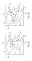
- FIGS. 3A and 3Bare diagrams showing example wireless signals communicated between wireless communication devices.
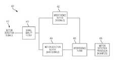
- FIG. 4is a diagram showing an example motion detection system that includes a motion detection buffer and an interference buffer.
- FIGS. 5A through 5Eare diagrams showing an example process of loading an interference buffer and a motion detection buffer.
- FIGS. 6A through 6Hare diagrams showing another example process of loading an interference buffer and a motion detection buffer.
- FIGS. 7A-7Care flow diagrams showing an example process of time-aligning time motion detection signals.
- motion detection signalsare time-aligned using buffers.
- interference and motion detection buffers of different lengthsare used to time-align motion detection signals for a motion detection process.
- An interference filtermakes a determination regarding a level of wireless interference present in the input signals in the interference buffer, and based on the determination, the motion detection process either executes or does not execute on input signals in the motion detection buffer.
- the interference filterdetermines whether an unacceptable interference level is present in a set of N input signals, and in response to the determination, the motion detection process may execute or not execute on the set of N input signals.
- the interference buffermay then obtain a second set of N input signals while the motion detection process is executed on the first set of N input signals.
- the motion detection processmay execute on M ⁇ N input signals at a time.
- the interference buffermay have space for N input signals and the motion detection buffer may have space for N+M ⁇ 1 input signals.
- motionmay be detected using wireless signals transmitted through a space.
- the embodiments of this disclosureprovide a complex filter (namely, the time alignment input signals) that can be applied to a large data set to determine whether the data on which a motion detection process is executed is “clouded” with interference signals or not.
- the complex filterBy time-aligning the data paths of the interference filter and the motion detection process, the complex filter has an opportunity to evaluate on more data and extract (or discard) features from the data set to ensure that motion detected in a space is genuinely motion of an object and not a false-positive caused by wireless interference present in the space.
- the motion detection processcan be executed in a pseudo real-time manner, with minimal delay.
- FIG. 1illustrates an example wireless communication system 100 .
- the example wireless communication system 100includes three wireless communication devices—a first wireless communication device 102 A, a second wireless communication device 102 B, and a third wireless communication device 102 C.
- the example wireless communication system 100may include additional wireless communication devices and other components (e.g., additional wireless communication devices, one or more network servers, network routers, network switches, cables, or other communication links, etc.).
- the example wireless communication devices 102 A, 102 B, 102 Ccan operate in a wireless network, for example, according to a wireless network standard or another type of wireless communication protocol.
- the wireless networkmay be configured to operate as a Wireless Local Area Network (WLAN), a Personal Area Network (PAN), a metropolitan area network (MAN), or another type of wireless network.
- WLANsinclude networks configured to operate according to one or more of the 802.11 family of standards developed by IEEE (e.g., Wi-Fi networks), and others.
- PANsinclude networks that operate according to short-range communication standards (e.g., BLUETOOTH®, Near Field Communication (NFC), ZigBee), millimeter wave communications, and others.
- the wireless communication devices 102 A, 102 B, 102 Cmay be configured to communicate in a cellular network, for example, according to a cellular network standard.
- cellular networksinclude networks configured according to 2G standards such as Global System for Mobile (GSM) and Enhanced Data rates for GSM Evolution (EDGE) or EGPRS; 3G standards such as Code Division Multiple Access (CDMA), Wideband Code Division Multiple Access (WCDMA), Universal Mobile Telecommunications System (UMTS), and Time Division Synchronous Code Division Multiple Access (TD-SCDMA); 4G standards such as Long-Term Evolution (LTE) and LTE-Advanced (LTE-A); and others.
- GSMGlobal System for Mobile
- EDGEEnhanced Data rates for GSM Evolution
- EGPRSEGPRS
- 3G standardssuch as Code Division Multiple Access (CDMA), Wideband Code Division Multiple Access (WCDMA), Universal Mobile Telecommunications System (UMTS), and Time Division Synchronous Code Division Multiple Access (TD-SCDMA)
- 4G standardssuch as Long-Term Evolution (
- the wireless communication devices 102 A, 102 B, 102 Ccan be, or they may include, standard wireless network components.
- the wireless communication devices 102 A, 102 B, 102 Cmay be commercially-available Wi-Fi access points or another type of wireless access point (WAP) performing one or more operations as described herein that are embedded as instructions (e.g., software or firmware) on the modem of the WAP.
- WAPwireless access point
- the wireless communication devices 102 A, 102 B, 102 Cmay be nodes of a wireless mesh network, such as, for example, a commercially-available mesh network system (e.g., GOOGLE WIFI).
- a commercially-available mesh network systeme.g., GOOGLE WIFI
- another type of standard or conventional Wi-Fi transmitter devicemay be used.
- the wireless communication devices 102 A, 102 B, 102 Cmay be implemented without Wi-Fi components; for example, other types of standard or non-standard wireless communication may be used for motion detection.
- the wireless communication devices 102 A, 102 B, 102 Ccan be, or they may be part of, a dedicated motion detection system.
- the dedicated motion detection systemcan include a hub device and one or more beacon devices (as remote sensor devices), and the wireless communication devices 102 A, 102 B, 102 C can be either a hub device or a beacon device in the motion detection system.
- the example wireless communication device 102 Cincludes a modem 112 , a processor 114 , a memory 116 , and a power unit 118 ; any of the wireless communication devices 102 A, 102 B, 102 C in the wireless communication system 100 may include the same, additional or different components, and the components may be configured to operate as shown in FIG. 1 or in another manner.
- the modem 112 , processor 114 , memory 116 , and power unit 118 of a wireless communication deviceare housed together in a common housing or other assembly.
- one or more of the components of a wireless communication devicecan be housed separately, for example, in a separate housing or other assembly.
- the example modem 112can communicate (receive, transmit, or both) wireless signals.
- the modem 112may be configured to communicate radio frequency (RF) signals formatted according to a wireless communication standard (e.g., Wi-Fi or Bluetooth).
- RFradio frequency
- the modem 112may be implemented as the example wireless network modem 112 shown in FIG. 1 , or may be implemented in another manner, for example, with other types of components or subsystems.
- the example modem 112includes a radio subsystem and a baseband subsystem.
- the baseband subsystem and radio subsystemcan be implemented on a common chip or chipset, or they may be implemented in a card or another type of assembled device.
- the baseband subsystemcan be coupled to the radio subsystem, for example, by leads, pins, wires, or other types of connections.
- a radio subsystem in the modem 112can include one or more antennas and radio frequency circuitry.
- the radio frequency circuitrycan include, for example, circuitry that filters, amplifies or otherwise conditions analog signals, circuitry that up-converts baseband signals to RF signals, circuitry that down-converts RF signals to baseband signals, etc. Such circuitry may include, for example, filters, amplifiers, mixers, a local oscillator, etc.
- the radio subsystemcan be configured to communicate radio frequency wireless signals on the wireless communication channels.
- the radio subsystemmay include a radio chip, an RF front end, and one or more antennas.
- a radio subsystemmay include additional or different components.
- the radio subsystemcan be or include the radio electronics (e.g., RF front end, radio chip, or analogous components) from a conventional modem, for example, from a Wi-Fi modem, pico base station modem, etc.
- the antennaincludes multiple antennas.
- a baseband subsystem in the modem 112can include, for example, digital electronics configured to process digital baseband data.
- the baseband subsystemmay include a baseband chip.
- a baseband subsystemmay include additional or different components.
- the baseband subsystemmay include a digital signal processor (DSP) device or another type of processor device.
- the baseband systemincludes digital processing logic to operate the radio subsystem, to communicate wireless network traffic through the radio subsystem, to detect motion based on motion detection signals received through the radio subsystem or to perform other types of processes.
- the baseband subsystemmay include one or more chips, chipsets, or other types of devices that are configured to encode signals and deliver the encoded signals to the radio subsystem for transmission, or to identify and analyze data encoded in signals from the radio subsystem (e.g., by decoding the signals according to a wireless communication standard, by processing the signals according to a motion detection process, or otherwise).
- the radio subsystem in the example modem 112receives baseband signals from the baseband subsystem, up-converts the baseband signals to radio frequency (RF) signals, and wirelessly transmits the radio frequency signals (e.g., through an antenna).
- the radio subsystem in the example modem 112wirelessly receives radio frequency signals (e.g., through an antenna), down-converts the radio frequency signals to baseband signals, and sends the baseband signals to the baseband subsystem.
- the signals exchanged between the radio subsystem and the baseband subsystemmay be digital or analog signals.
- the baseband subsystemincludes conversion circuitry (e.g., a digital-to-analog converter, an analog-to-digital converter) and exchanges analog signals with the radio subsystem.
- the radio subsystemincludes conversion circuitry (e.g., a digital-to-analog converter, an analog-to-digital converter) and exchanges digital signals with the baseband subsystem.
- the baseband subsystem of the example modem 112can communicate wireless network traffic (e.g., data packets) in the wireless communication network through the radio subsystem on one or more network traffic channels.
- the baseband subsystem of the modem 112may also transmit or receive (or both) signals (e.g., motion probe signals or motion detection signals) through the radio subsystem on a dedicated wireless communication channel.
- the baseband subsystemgenerates motion probe signals for transmission, for example, to probe a space for motion.
- the baseband subsystemprocesses received motion detection signals (signals based on motion probe signals transmitted through the space), for example, to detect motion of an object in a space.
- the example processor 114can execute instructions, for example, to generate output data based on data inputs.
- the instructionscan include programs, codes, scripts, or other types of data stored in memory. Additionally or alternatively, the instructions can be encoded as pre-programmed or re-programmable logic circuits, logic gates, or other types of hardware or firmware components.
- the processor 114may be or include a general-purpose microprocessor, as a specialized co-processor or another type of data processing apparatus. In some cases, the processor 114 performs high level operation of the wireless communication device 102 C.
- the processor 114may be configured to execute or interpret software, scripts, programs, functions, executables, or other instructions stored in the memory 116 . In some implementations, the processor 114 may be included in the modem 112 .
- the example memory 116can include computer-readable storage media, for example, a volatile memory device, a non-volatile memory device, or both.
- the memory 116can include one or more read-only memory devices, random-access memory devices, buffer memory devices, or a combination of these and other types of memory devices. In some instances, one or more components of the memory can be integrated or otherwise associated with another component of the wireless communication device 102 C.
- the memory 116may store instructions that are executable by the processor 114 .
- the instructionsmay include instructions for time-aligning signals using an interference buffer and a motion detection buffer, such as through one or more of the operations of the example process 700 of FIGS. 7A-7C .
- the example power unit 118provides power to the other components of the wireless communication device 102 C.
- the other componentsmay operate based on electrical power provided by the power unit 118 through a voltage bus or other connection.
- the power unit 118includes a battery or a battery system, for example, a rechargeable battery.
- the power unit 118includes an adapter (e.g., an AC adapter) that receives an external power signal (from an external source) and coverts the external power signal to an internal power signal conditioned for a component of the wireless communication device 102 C.
- the power unit 118may include other components or operate in another manner.
- the wireless communication devices 102 A, 102 Btransmit wireless signals (e.g., according to a wireless network standard, a motion detection protocol, or otherwise).
- wireless communication devices 102 A, 102 Bmay broadcast wireless motion probe signals (e.g., reference signals, beacon signals, status signals, etc.), or they may send wireless signals addressed to other devices (e.g., a user equipment, a client device, a server, etc.), and the other devices (not shown) as well as the wireless communication device 102 C may receive the wireless signals transmitted by the wireless communication devices 102 A, 102 B.
- the wireless signals transmitted by the wireless communication devices 102 A, 102 Bare repeated periodically, for example, according to a wireless communication standard or otherwise.
- the wireless communication device 102 Cprocesses the wireless signals from the wireless communication devices 102 A, 102 B to detect motion of an object in a space accessed by the wireless signals, to determine a location of the detected motion, or both.
- the wireless communication device 102 Cmay perform one or more operations of the example processes described below with respect to FIGS. 3-9 , or another type of process for detecting motion or determining a location of detected motion.
- the space accessed by the wireless signalscan be an indoor or outdoor space, which may include, for example, one or more fully or partially enclosed areas, an open area without enclosure, etc.
- the spacecan be or can include an interior of a room, multiple rooms, a building, or the like.
- the wireless communication system 100can be modified, for instance, such that the wireless communication device 102 C can transmit wireless signals and the wireless communication devices 102 A, 102 B can processes the wireless signals from the wireless communication device 102 C to detect motion or determine a location of detected motion.
- the wireless signals used for motion detectioncan include, for example, a beacon signal (e.g., Bluetooth Beacons, Wi-Fi Beacons, other wireless beacon signals), another standard signal generated for other purposes according to a wireless network standard, or non-standard signals (e.g., random signals, reference signals, etc.) generated for motion detection or other purposes.
- the wireless signalspropagate through an object (e.g., a wall) before or after interacting with a moving object, which may allow the moving object's movement to be detected without an optical line-of-sight between the moving object and the transmission or receiving hardware.
- the third wireless communication device 102 Cmay generate motion detection data.
- the third wireless communication device 102 Cmay communicate the motion detection data to another device or system, such as a security system, that may include a control center for monitoring movement within a space, such as a room, building, outdoor area, etc.
- the wireless communication devices 102 A, 102 Bcan be modified to transmit motion probe signals (which may include, e.g., a reference signal, beacon signal, or another signal used to probe a space for motion) on a separate wireless communication channel (e.g., a frequency channel or coded channel) from wireless network traffic signals.
- motion probe signalswhich may include, e.g., a reference signal, beacon signal, or another signal used to probe a space for motion
- a separate wireless communication channele.g., a frequency channel or coded channel
- the modulation applied to the payload of a motion probe signal and the type of data or data structure in the payloadmay be known by the third wireless communication device 102 C, which may reduce the amount of processing that the third wireless communication device 102 C performs for motion sensing.
- the headermay include additional information such as, for example, an indication of whether motion was detected by another device in the communication system 100 , an indication of the modulation type, an identification of the device transmitting the signal, etc.
- the wireless communication system 100is a wireless mesh network, with wireless communication links between each of the respective wireless communication devices 102 .
- the wireless communication link between the third wireless communication device 102 C and the first wireless communication device 102 Acan be used to probe a first motion detection field 110 A
- the wireless communication link between the third wireless communication device 102 C and the second wireless communication device 102 Bcan be used to probe a second motion detection field 110 B
- the wireless communication link between the first wireless communication device 102 A and the second wireless communication device 102 Bcan be used to probe a third motion detection field 110 C.
- each wireless communication device 102detects motion in the motion detection fields 110 accessed by that device by processing received signals that are based on wireless signals transmitted by the wireless communication devices 102 through the motion detection fields 110 .
- the wireless communication devices 102may detect the motion based on signals they received that are based on wireless signals transmitted through the respective motion detection fields 110 .
- the first wireless communication device 102 Acan detect motion of the person in both motion detection fields 110 A, 110 C
- the second wireless communication device 102 Bcan detect motion of the person 106 in the motion detection field 110 C
- the third wireless communication device 102 Ccan detect motion of the person 106 in the motion detection field 110 A.
- the motion detection fields 110can include, for example, air, solid materials, liquids, or another medium through which wireless electromagnetic signals may propagate.
- the first motion detection field 110 Aprovides a wireless communication channel between the first wireless communication device 102 A and the third wireless communication device 102 C
- the second motion detection field 110 Bprovides a wireless communication channel between the second wireless communication device 102 B and the third wireless communication device 102 C
- the third motion detection field 110 Cprovides a wireless communication channel between the first wireless communication device 102 A and the second wireless communication device 102 B.
- wireless signals transmitted on a wireless communication channelare used to detect movement of an object in a space.
- the objectscan be any type of static or moveable object, and can be living or inanimate.
- the objectcan be a human (e.g., the person 106 shown in FIG. 1 ), an animal, an inorganic object, or another device, apparatus, or assembly), an object that defines all or part of the boundary of a space (e.g., a wall, door, window, etc.), or another type of object.
- motion information from the wireless communication devicesmay be analyzed to determine a location of the detected motion. For example, as described further below, one of the wireless communication devices 102 (or another device communicably coupled to the devices 102 ) may determine that the detected motion is nearby a particular wireless communication device.
- FIG. 2illustrates an example motion probe signal 202 .
- the example motion probe signal 202can be transmitted, for example, in a wireless communication system to monitor for motion in a space.
- the motion probe signal 202is implemented as a packet.
- the motion probe signal 202can include binary data that is converted to an analog signal, up-converted to radio frequency, and wirelessly transmitted by an antenna.
- the motion probe signal 202 shown in FIG. 2includes control data 204 and a motion data 206 .
- a motion probe signal 202may include additional or different features, and may be formatted in another manner.
- the control data 204may include the type of control data that would be included in a conventional data packet.
- the control data 204may include a preamble (also called a header) indicating the type of information contained in the motion probe signal 202 , an identifier of a wireless device transmitting the motion probe signal 202 , a MAC address of a wireless device transmitting the motion probe signal 202 , a transmission power, etc.
- the motion data 206is the payload of the motion probe signal 202 .
- the motion data 206can be or include, for example, a pseudorandom code or another type of reference signal.
- the motion data 206can be or include, for example, a beacon signal broadcast by a wireless network system.
- the motion probe signal 202is transmitted by a wireless device (e.g., the wireless communication device 102 A shown in FIG. 1 ) and received at a motion detection device (e.g., the wireless communication device 102 C shown in FIG. 1 ).
- the control data 204changes with each transmission, for example, to indicate the time of transmission or updated parameters.
- the motion data 206can remain unchanged in each transmission of the motion probe signal 202 .
- the receiving wireless communication devicecan process the received signals based on each transmission of the motion probe signal 202 , and analyze the motion data 206 for changes. For instance, changes in the motion data 206 may indicate movement of an object in a space accessed by the wireless transmission of the motion probe signal 202 .
- the motion data 206can then be processed, for example, to generate a response to the detected motion.
- FIGS. 3A and 3Bare diagrams showing example wireless signals communicated between wireless communication devices 304 A, 304 B, 304 C.
- the wireless communication devices 304 A, 304 B, 304 Ccan be, for example, the wireless communication devices 102 A, 102 B, 102 C shown in FIG. 1 , or other types of wireless communication devices.
- the example wireless communication devices 304 A, 304 B, 304 Ctransmit wireless signals through a space 300 .
- the example space 300can be completely or partially enclosed or open at one or more boundaries of the space 300 .
- the space 300can be or can include an interior of a room, multiple rooms, a building, an indoor area, outdoor area, or the like.
- a first wall 302 A, a second wall 302 B, and a third wall 302 Cat least partially enclose the space 300 in the example shown.
- the first wireless communication device 304 Ais operable to transmit wireless signals repeatedly (e.g., periodically, intermittently, at scheduled, unscheduled or random intervals, etc.).
- the transmitted signalsmay be formatted like the motion probe signal 202 of FIG. 2 , or in another manner.
- the second and third wireless communication devices 304 B, 304 Care operable to receive signals based on those transmitted by the wireless communication device 304 A.
- the wireless communication devices 304 B, 304 Ceach have a modem (e.g., the modem 112 shown in FIG. 1 ) that is configured to process received signals to detect motion of an object in the space 300 .
- the moving object in the space 300is represented as a human, but the moving object can be another type of object.
- the moving objectcan be an animal, an inorganic object (e.g., a system, device, apparatus, or assembly), an object that defines all or part of the boundary of the space 300 (e.g., a wall, door, window, etc.), or another type of object.
- first wireless communication device 304 Amultiple example paths of the wireless signals transmitted from the first wireless communication device 304 A are illustrated by dashed lines.
- first signal path 316the wireless signal is transmitted from the first wireless communication device 304 A and reflected off the first wall 302 A toward the second wireless communication device 304 B.
- second signal path 318the wireless signal is transmitted from the first wireless communication device 304 A and reflected off the second wall 302 B and the first wall 302 A toward the third wireless communication device 304 C.
- third signal path 320the wireless signal is transmitted from the first wireless communication device 304 A and reflected off the second wall 302 B toward the third wireless communication device 304 C.
- fourth signal path 322the wireless signal is transmitted from the first wireless communication device 304 A and reflected off the third wall 302 C toward the second wireless communication device 304 B.
- the wireless signalis transmitted from the first wireless communication device 304 A and reflected off the object at the first position 314 A toward the third wireless communication device 304 C.
- a surface of the objectmoves from the first position 314 A to a second position 314 B in the space 300 (e.g., some distance away from the first position 314 A).
- the wireless signalis transmitted from the first wireless communication device 304 A and reflected off the object at the second position 314 B toward the third wireless communication device 304 C.
- a signal pathcan be added, removed, or otherwise modified due to movement of an object in a space.
- the example wireless signals shown in FIGS. 3A and 3Bmay experience attenuation, frequency shifts, phase shifts, or other effects through their respective paths and may have portions that propagate in another direction, for example, through the walls 302 A, 302 B, and 302 C.
- the wireless signalsare radio frequency (RF) signals.
- the wireless signalsmay include other types of signals.
- the first wireless communication device 304 Acan repeatedly transmit a wireless signal.
- FIG. 3Ashows the wireless signal being transmitted from the first wireless communication device 304 A at a first time
- FIG. 3Bshows the same wireless signal being transmitted from the first wireless communication device 304 A at a second, later time.
- the transmitted signalcan be transmitted continuously, periodically, at random or intermittent times or the like, or a combination thereof.
- the transmitted signalcan have a number of frequency components in a frequency bandwidth.
- the transmitted signalcan be transmitted from the first wireless communication device 304 A in an omnidirectional manner, in a directional manner or otherwise.
- the wireless signalstraverse multiple respective paths in the space 300 , and the signal along each path may become attenuated due to path losses, scattering, reflection, or the like and may have a phase or frequency offset.
- the signals from various paths 316 , 318 , 320 , 322 , 324 A, and 324 Bcombine at the third wireless communication device 304 C and the second wireless communication device 304 B to form received signals.
- the space 300may be represented as a transfer function (e.g., a filter) in which the transmitted signal is input and the received signal is output.
- the transfer function of the space 300can change.
- a change in the received signalcan be used to detect movement of an object.
- a transmitted signal f(t) transmitted from the first wireless communication device 304 Amay be described according to Equation (1):
- Equation (2)an output signal r k (t) from a path k may be described according to Equation (2):
- ⁇ n,krepresents an attenuation factor (or channel response; e.g., due to scattering, reflection, and path losses) for the n th frequency component along path k
- ⁇ n,krepresents the phase of the signal for n th frequency component along path k.
- Equation (3)Equation (3)
- the received signal R at a wireless communication devicecan then be analyzed.
- the received signal R at a wireless communication devicecan be transformed to the frequency domain, for example, using a Fast Fourier Transform (FFT) or another type of algorithm.
- the transformed signalcan represent the received signal R as a series of n complex values, one for each of the respective frequency components (at the n frequencies ⁇ n ).
- a complex value H nmay be represented as follows in Equation (5):
- H n⁇ k ⁇ c n ⁇ ⁇ n , k ⁇ e j ⁇ ⁇ ⁇ n , k . ( 5 )
- the complex value H n for a given frequency component ⁇ nindicates a relative magnitude and phase offset of the received signal at that frequency component ⁇ n .
- the complex value H nchanges due to the channel response ⁇ n,k of the space changing. Accordingly, a change detected in the channel response can be indicative of movement of an object within the communication channel.
- noise, interference, or other phenomenacan influence the channel response detected by the receiver, and the motion detection system can reduce or isolate such influences to improve the accuracy and quality of motion detection capabilities.
- the overall channel responsecan be represented as:
- the channel response h ch for a spacecan be determined, for example, based on the mathematical theory of estimation. For instance, a reference signal R ef can be modified with candidate channel responses (h ch ), and then a maximum likelihood approach can be used to select the candidate channel which gives best match to the received signal (R cvd ). In some cases, an estimated received signal ( ⁇ circumflex over (R) ⁇ cvd ) is obtained from the convolution of the reference signal (R ef ) with the candidate channel responses (h ch ), and then the channel coefficients of the channel response (h ch ) are varied to minimize the squared error of the estimated received signal ( ⁇ circumflex over (R) ⁇ cvd ). This can be mathematically illustrated as:
- the minimizing, or optimizing, processcan utilize an adaptive filtering technique, such as Least Mean Squares (LMS), Recursive Least Squares (RLS), Batch Least Squares (BLS), etc.
- LMSLeast Mean Squares
- RLSRecursive Least Squares
- BLSBatch Least Squares
- the channel responsecan be a Finite Impulse Response (FIR) filter, Infinite Impulse Response (IIR) filter, or the like.
- the received signalcan be considered as a convolution of the reference signal and the channel response.
- the convolution operationmeans that the channel coefficients possess a degree of correlation with each of the delayed replicas of the reference signal.
- the convolution operation as shown in the equation abovetherefore shows that the received signal appears at different delay points, each delayed replica being weighted by the channel coefficient.
- a signal quality metricmay be determined for received signals based on the channel response. For example, a determined channel response (h ch ) for a space may be applied to a reference signal (R ef ) to yield an estimated received signal ( ⁇ circumflex over (R) ⁇ cvd ), which is an estimation of what the received signal should be based on the channel response (e.g., based on convolution of the reference signal (R ef ) with the channel response (h ch ) as described above). The estimated received signal ( ⁇ circumflex over (R) ⁇ cvd ) and the actual received signal (R cvd ) may be used to compute a signal quality metric.
- received signalsmay be “rejected” by a wireless communication device.
- a motion detection processmay include quality criterion for signals. Received signals that do not meet the quality criterion may be rejected (e.g., discarded or ignored) and not considered in determining whether motion has occurred in the space 300 . The signals may be accepted or rejected as inputs to the motion detection process based on the signal quality metric (e.g., the value Q described by Equation (9)). For instance, in some cases, motion is detected using only a subset of received signals that have values Q above a certain threshold.
- the signal quality metrice.g., the value Q described by Equation (9)
- FIG. 4is a diagram showing an example motion detection system 400 that includes a motion detection buffer 404 and an interference buffer 402 .
- the system 400can be included in a wireless communication device (for example, wireless communication device 304 C shown in FIGS. 3A and 3B ) and can receive wireless signals based on those transmitted by another wireless communication device (for example, wireless communication device 304 A).
- the system 400implements a time alignment process on the motion detection signals 412 .
- the system 400provides the motion detection signals 412 to the interference buffer 402 and the motion detection buffer 404 to time-align the signals, and based on the interference filter 406 applied to the signals in the interference buffer 402 , signals in the motion detection buffer 403 are provided to the motion detection processor 408 for analysis.
- the motion detection signals 412 received by the system 400may be based on a motion probe signal (e.g., the motion probe signal 202 shown in FIG. 2 ) transmitted through a space (e.g., the space 300 shown in FIGS. 3A-3B ).
- each motion detection signal 412may be based on a respective motion probe signal transmitted through the space.
- the motion detection signal 412may differ from the motion probe signal based on the channel response, as described above.
- the motion detection signals 412may be obtained from a modem of a wireless communication device (e.g., the modem 112 of FIG. 1 ).
- the motion detection signals 412are input to the signal quality filter 410 .
- the signal quality filter 410analyzes the motion detection signals 412 based on one or more quality criterion. For example, the signal quality filter 410 may determine a signal quality metric value (e.g., the value Q described by Equation (9) above) for each motion detection signal 412 , and compare the signal quality metric value with the quality criterion. The signal quality filter 410 either accepts or rejects the motion detection signals 412 based on the comparison with the quality criterion.
- a signal quality metric valuee.g., the value Q described by Equation (9) above
- the signal quality filter 410may reject the motion detection signal 412 when the comparison result indicates that the signal quality metric value Q for the motion detection signal fails to meet the quality criterion, such as, for example, when the Q value is less than a signal quality metric threshold value.
- the signal quality filter 410accepts the motion detection signal 412 when the comparison result indicates that the Q value for the sample meets the quality criterion, for example, when Q value is greater than the signal quality metric threshold value. If accepted, the motion detection signal 412 is input to both the motion detection buffer 404 and the interference buffer 402 . In certain implementations, the system 400 does not include the signal quality filter 410 .
- the interference buffer 402includes N data blocks that and the motion detection buffer 404 includes N+M ⁇ 1 data blocks, where M ⁇ N.
- Each data block of the interference buffer 402 and the motion detection buffer 404can store a motion detection signal 412 .
- the buffers 402 , 404are filled in a first-in/first-out fashion.
- a motion detection signal 412 received firstis stored in a first data block of the interference buffer 402 until a second motion detection signal 412 is received, at which time the motion detection signal 412 received first is stored in a second data block of the interference buffer 402 while the second motion detection signal 412 is stored in the first data block, and so forth until the motion detection signal 412 received first is stored in the N th data block of the interference buffer 402 .
- the interference filter 406determines a wireless interference level in the motion detection signals 412 .
- the interference filtermay apply an interference filter function f(x) to the N motion detection signals stored in the interference buffer 402 .
- the interference filter 406accesses the set of N motion detection signals in interference buffer 402 in response to determining that the interference buffer 402 is full.
- the wireless interference metric determined by the interference filter 406can be stored in correspondence to each of N motion detection signals used in the detection.
- the wireless interference level determined by the interference filter 406represents a wireless interference level corresponding to a period time during which the motion detection signals 412 were received.
- the interference filter 406may determine a first wireless interference metric corresponding to a first set of N input signals loaded into the interference buffer 402 over a time period (t 1 ⁇ t N ) by applying the interference filter function f(x) to the first set of N input signals, and a second wireless interference metric for a second set of N input signals loaded into the interference buffer 402 over a time period (t N+1 ⁇ t 2N ) by applying the interference filter function f(x) to the second set of N input signals.
- the interference filter 406compares the wireless interference level with a threshold (e.g., compares the interference metric with a threshold interference value). If the wireless interference metric is at or above the threshold interference value, the system 400 prevents the motion detection processor 408 from executing the motion detection process on the signals in the motion detection buffer 408 . That is, the interference filter 406 blocks the motion detection processor 408 from applying a motion detection process to any of the N motion detection signals in the motion detection buffer 404 corresponding to the N motion detection signals in the interference buffer 402 . By blocking execution, the interference filter 406 ensures that the motion detection processor 408 does not execute a motion detection process on noisy signals (i.e., signals having an unacceptably high wireless interference level).
- a thresholde.g., compares the interference metric with a threshold interference value
- the interference filter 406allows execution of the motion detection process on the corresponding N motion detection signals in the motion detection buffer 404 .
- the interference buffer 402may be cleared after the interference filter 406 runs on the N signals, and a second set of motion detection signals 412 is loaded into the interference buffer 402 .
- the interference filter 406can repeat the process of detecting that the interference buffer 402 is full, determining a wireless interference level, and allowing/preventing execution of the motion detection process on the new set of N motion detection signals by the motion detection processor 408 .
- the interference filter 406can include or perform the function of an interference gate (e.g., logic gate; AND gate) by selectively: (i) allowing the motion detection processor 408 to execute the motion detection process on a subset (e.g., M signals) of the N+M ⁇ 1 motion detection signals stored in the motion detection buffer 404 ; or (ii) blocking the motion detection processor 408 from executing the motion detection process on the subset M.
- the interference filter 406evaluates the past N moments as a collection before the motion detection processor 408 executes the motion detection process using a subset M of the N moments.
- FIGS. 5A through 5Eare diagrams showing an example process of loading an interference buffer 502 and a motion detection buffer 504 .
- the interference buffer 502 of FIG. 5can be the same as or similar to the interference buffer 402 shown in FIG. 4
- the motion detection buffer 504 of FIG. 5can be the same as or similar to the motion detection buffer 404 shown in FIG. 4
- the example interference buffer 502includes N data blocks configured to respectively store N motion detection signals, for example, the motion detection signals 412 of FIG. 4 .
- the motion detection buffer 504includes N+M ⁇ 1 data blocks configured to respectively store N+M ⁇ 1 motion detection signals, for example, the motion detection signals 412 of FIG. 4 .
- the interference buffer 502 and motion detection buffer 504are loaded in a first-in/first-out fashion.
- the remainder of the data blocksare empty in the interference buffer 502 and motion detection buffer 504 .
- the first data blocks 505 and 508have an index of 1.
- the latest input signalnamely, the N th input signal S(N)
- the first input signal S( 1 )is loaded into the N th data blocks 516 and 518 of the interference buffer 502 and motion detection buffer 504 , respectively.
- the second data blocks 510 and 512 of the interference buffer 502 and motion detection buffer 504have an index of 2; the penultimate data block 514 of the interference buffer 502 has an index of N ⁇ 1; the N th data blocks 516 and 518 of the interference buffer 502 and motion detection buffer 504 , respectively, have an index of N; and the last data block 520 of the motion detection buffer 504 has an index of N+M ⁇ 1.
- the N data blocks in the interference buffer 502are full and the 1-N th data blocks in the motion detection buffer 504 are loaded identically as the N data blocks in the interference buffer 502 (loaded with signals S( 1 ) through S(N)). The remainder of the data blocks in the motion detection buffer 504 are empty.
- a subset 506 of M data blocks within the motion detection buffer 504are accessible to a motion detection processor, for example, the motion detection processor 408 of FIG. 4 .
- the motion detection processorcan determine that the subset 506 of M data blocks is full by detecting that a data block of interest is loaded with a sample.
- the data block of interestcan be the last data block 520 of the motion detection buffer 504 .
- the N th data block 518 of the motion detection buffer 504is the first data block of the subset 506 of M data blocks within the motion detection buffer 504 .
- an interference filter function f(x)is applied to the set of N signals ⁇ S(N), S(N ⁇ 1), . . . , S( 2 ), S( 1 ) ⁇ within the full interference buffer 502 .
- An interference gate(described below) can hold the result of the interference filter function as its output, and control whether or not a motion detection process is executed on the M data blocks 506 of the motion detection buffer 504 . After the interference filter function is run, the interference buffer 502 is cleared.
- the latest input signalnamely, the N+1 th input signal S(N+1)
- the motion detection buffer 504continues to be filled in a first-in/first-out manner, even after the interference buffer 502 is cleared and reloaded.
- the remainder of the data blocks in motion detection buffer 504are empty.
- the interference buffer 502is loaded with a second set of N motion detection signals; the motion detection buffer 504 is full; and a motion detection process may be executed on the set of M samples ⁇ S(M), S(M ⁇ 1), . . . , S( 2 ), S( 1 ) ⁇ loaded in the subset 506 of M data blocks in the motion detection buffer 504 (e.g., in response to a determination that a level of interference in the first set of N signals is below a threshold, as described above).
- the motion detection processorexecutes (or is blocked from executing) a motion detection process on the subset 506 to detect motion that occurred in a space (e.g., space 300 of FIGS. 3A and 3B ).
- a spacee.g., space 300 of FIGS. 3A and 3B .
- the motion detection systemcontinues the cycle of: (i) loading the latest input signal into the first data blocks 505 and 508 of the interference buffer 502 and motion detection buffer 504 , respectively, in a first-in/first-out manner; and (ii) executing (or blocking execution of) a motion detection process on the set of M samples loaded in the subset 506 of M data blocks, based on the output of an interference function filter (e.g., interference gate).
- an interference function filtere.g., interference gate
- the latest input signalnamely, the 2N th input signal S(2N)
- the N+1 th input signal S(N+1)is loaded into the N th data blocks 516 and 518 of the interference buffer 502 and motion detection buffer 504 .
- the first through N th data blocks in the motion detection buffer 504are loaded identically as the N data blocks in the interference buffer 502 , namely loaded with samples S(2N) through S(N+1).
- the remainder of the data blocksare full in the motion detection buffer 504 , namely, filled with samples ⁇ S(N+1), S(N), . . . , S(N ⁇ M+3), S(N ⁇ M+2) ⁇ from the second set of input signals.
- the interference filter function f(x)is applied to the second set of N samples ⁇ S(2N), S(2N ⁇ 1), . . .
- the interference gatecontrols whether or not a motion detection process is executed on the subset 506 of M data blocks within the motion detection buffer 504 , as described above.
- the input signals loaded into the interference buffer and motion detection buffercan be represented by a sample corresponding to a time index.
- the input signal received firstcould be represented by time index t 0 ; the second input signal could be represented by time index t 1 ; the N th input signal could be represented as a sample corresponding to the N th point in time t 31 ; the first input signal of a second set of N input signals could be represented as a sample corresponding to the N+1 th time index t 32 ; and the 2N th input signal could be represented as a sample corresponding to the 2N th point in time t 63 .
- FIGS. 6A through 6Hare diagrams showing another example process of loading an interference buffer 602 and a motion detection buffer 604 .
- the interference buffer 602 and motion detection buffer 604are loaded with motion detection signals in the same manner as described above with respect to the interference buffer 502 and motion detection buffer 504 of FIG. 5 .
- FIGS. 7A-7Care flow diagrams showing an example process 700 of time-aligning time motion detection signals.
- the process 700may be implemented to detect motion of an object in a space based on signals transmitted on a selected wireless communication channel.
- Operations in the example process 700may be performed by a data processing apparatus (e.g., the processor 114 of the example wireless communication device 102 C in FIG. 1 ) to detect motion based on signals received at wireless communication devices (e.g., wireless communication device 102 C of FIG. 1 ).
- the example process 700may be performed by another type of device.
- operations of the process 700may be performed by a system other than the wireless communication device 102 C that receives the signals (e.g., a computer system connected to the wireless communication system 100 of FIG. 1 that aggregates and analyzes signals received by the wireless communication device 102 C).
- the example process 700may include additional or different operations, and the operations may be performed in the order shown or in another order.
- one or more of the operations shown in FIGS. 7A-7Care implemented as processes that include multiple operations, sub-processes or other types of routines.
- operationscan be combined, performed in another order, performed in parallel, iterated, or otherwise repeated or performed another manner.
- a set of N motion detection signalsare obtained.
- the motion detection signalsmay include frequency-domain representations of wireless signals received at a wireless communication device, or channel responses associated with a space.
- the received wireless signalsmay be based on wireless signals transmitted through a space during a first time period.
- the motion detection signals obtained at 702may be channel responses determined at one of wireless communication devices 304 B, 304 C based on the wireless signals transmitted through the space 300 by the wireless communication device 304 A.
- the set of N motion detection signalsmay be obtained by loading the motion detection signals into an interference buffer (and motion detection buffer) in a first-in/first-out manner, as described above.
- the set of N motion detection signalsare quality-verified.
- the set of N motion detection signalsare obtained at 702 by receiving an input signal (e.g., the motion detection signal 412 ), determining, at 708 , a signal quality metric value (e.g., the value Q described above in Equation (9)) for the signal.
- the signal quality metric valueis compared to a quality criterion (e.g., signal quality metric threshold value), and the motion detection signal is either rejected at 712 when the comparison result indicates that the Q value for the input signal fails to meet the quality criterion or accepted and loaded into both an interference buffer and motion detection buffer at 714 .
- a quality criterione.g., signal quality metric threshold value
- an interference level in the set of motion detection signals obtained at 702is determined. If the interference level is relatively low (e.g., indicating that any interference in the space is unlikely to affect the motion detection process), then a motion detection process is executed at 706 to detect motion of an object in the space based on subsets of the set of N motion detection signals. If the interference level is relatively high, then the first set of N motion detection signals are discarded or disregarded, and a second set of N motion detection signals are obtained at 702 .
- the level of interferencemay be determined using a wireless interference metric for the set of N motion detection signals.
- the determination of an interference level in motion detection signals obtained at 702is made by determining, at 722 , a wireless interference metric based on the set of N motion detection signals obtained at 702 , and comparing, at 724 , the determined wireless interference metric with the threshold interference value.
- the threshold interference valuemay be based on a magnitude of variation seen in interference signals that can affect (e.g., produce errors in) a motion detection process.
- a wireless interference metricis determined based on the set of N motion detection signals. For instance, referring to the example shown in FIG.
- the interference filter 406may analyze variations in the channel response over the set of N motion detection signals 416 stored in the interference buffer 402 by applying an interference filter function f(x) to the set of N motion detection signals 416 .
- the interference filter function f(x)evaluates N motion detection signals, the wireless interference metric is determined after the interference buffer 402 has been loaded with a set of N motion detection signals.
- the wireless interference metricis compared to a threshold interference value. If the wireless interference metric is at or above the threshold interference value, then a motion detection process is blocked from execution on the set of N motion detection signals at 726 . If the wireless interference metric is below the threshold interference value, then the motion detection process executes on the set of N motion detection signals at 728 .
- the interference filter 406includes an interference gate having an output provided to the motion detection processor 408 that controls whether the motion detection processor 408 executes or is blocked (or otherwise prevented) from executing a motion detection process on the set of N motion detection signals. In some cases, the set of N motion detection signals are deleted from the interference buffer after the determination at 722 .
- a motion detection processis executed using a subset M of the N motion detection signals.
- a new set of N motion detection signalsare obtained over a second time period while the motion detection process executes on the subsets M of the N motion detection signals from the first time period (e.g., as described above with respect to FIGS. 5, 6 ).
- the second set of N motion detection signalsmay be obtained in the same manner as those at 702 .
- the motion detection bufferincludes more than N data blocks, and obtaining the new set of N motion detection signals includes filling the motion detection buffer with the new set of N motion detection signals while storing a portion of the first set of N motion detection signals. Referring to the examples shown in FIGS.
- motionis detected based on the M signals within the subset 506 of the motion detection buffer 504 , while second set of motion detection signals ⁇ S(2N), S(2N ⁇ 1), . . . , S(N+1)) is loaded into both the interference buffer 502 and motion detection buffer 504 .
- the motion detection process at 706may compare information about the type of channel response variation (e.g., complex frequency components) of the subset of motion detection signals with information about previously-obtained channel responses to determine whether the type of channel response variation of the subset of motion detection signals indicates motion of an object in the space. For example, the motion detection process may analyze one or more statistical parameters of the channel response of the motion detection signals obtained at 702 (e.g., statistical parameters of frequency components of the channel response) to determine whether an object is moving in the space. In some implementations, the motion detection process at 706 may analyze statistical parameters of the received wireless signals themselves.
- the type of channel response variatione.g., complex frequency components
- Some of the subject matter and operations described in this specificationcan be implemented in digital electronic circuitry, or in computer software, firmware, or hardware, including the structures disclosed in this specification and their structural equivalents, or in combinations of one or more of them.
- Some of the subject matter described in this specificationcan be implemented as one or more computer programs, i.e., one or more modules of computer program instructions, encoded on a computer-readable storage medium for execution by, or to control the operation of, data-processing apparatus.
- a computer-readable storage mediumcan be, or can be included in, a computer-readable storage device, a computer-readable storage substrate, a random or serial access memory array or device, or a combination of one or more of them.
- a computer-readable storage mediumis not a propagated signal
- a computer-readable storage mediumcan be a source or destination of computer program instructions encoded in an artificially generated propagated signal.
- the computer-readable storage mediumcan also be, or be included in, one or more separate physical components or media (e.g., multiple CDs, disks, or other storage devices).
- the computer-readable storage mediumcan include multiple computer-readable storage devices.
- the computer-readable storage devicesmay be co-located (instructions stored in a single storage device), or located in different locations (e.g., instructions stored in distributed locations).
- data processing apparatuscan be implemented as operations performed by a data processing apparatus on data stored in memory (e.g., on one or more computer-readable storage devices) or received from other sources.
- data processing apparatusencompasses all kinds of apparatus, devices, and machines for processing data, including by way of example a programmable processor, a computer, a system on a chip, or multiple ones, or combinations, of the foregoing.
- the apparatuscan include special purpose logic circuitry, e.g., an FPGA (field programmable gate array) or an ASIC (application specific integrated circuit).
- the apparatuscan also include, in addition to hardware, code that creates an execution environment for the computer program in question, e.g., code that constitutes processor firmware, a protocol stack, a database management system, an operating system, a cross-platform runtime environment, a virtual machine, or a combination of one or more of them.
- the data processing apparatusincludes a set of processors.
- the set of processorsmay be co-located (e.g., multiple processors in the same computing device) or located in different location from one another (e.g., multiple processors in distributed computing devices).
- the memory storing the data executed by the data processing apparatusmay be co-located with the data processing apparatus (e.g., a computing device executing instructions stored in memory of the same computing device), or located in a different location from the data processing apparatus (e.g., a client device executing instructions stored on a server device).
- a computer program(also known as a program, software, software application, script, or code) can be written in any form of programming language, including compiled or interpreted languages, declarative or procedural languages, and it can be deployed in any form, including as a stand-alone program or as a module, component, subroutine, object, or other unit suitable for use in a computing environment.
- a computer programmay, but need not, correspond to a file in a file system.
- a programcan be stored in a portion of a file that holds other programs or data (e.g., one or more scripts stored in a markup language document), in a single file dedicated to the program, or in multiple coordinated files (e.g., files that store one or more modules, sub programs, or portions of code).
- a computer programcan be deployed to be executed on one computer or on multiple computers that are located at one site or distributed across multiple sites and interconnected by a communication network.
- Some of the processes and logic flows described in this specificationcan be performed by one or more programmable processors executing one or more computer programs to perform actions by operating on input data and generating output.
- the processes and logic flowscan also be performed by, and apparatus can also be implemented as, special purpose logic circuitry, e.g., an FPGA (field programmable gate array) or an ASIC (application specific integrated circuit).
- processors suitable for the execution of a computer programinclude, by way of example, both general and special purpose microprocessors, and processors of any kind of digital computer.
- a processorwill receive instructions and data from a read-only memory or a random-access memory or both.
- Elements of a computercan include a processor that performs actions in accordance with instructions, and one or more memory devices that store the instructions and data.
- a computermay also include, or be operatively coupled to receive data from or transfer data to, or both, one or more mass storage devices for storing data, e.g., non-magnetic drives (e.g., a solid-state drive), magnetic disks, magneto optical disks, or optical disks.
- a computerneed not have such devices.
- a computercan be embedded in another device, e.g., a phone, a tablet computer, an electronic appliance, a mobile audio or video player, a game console, a Global Positioning System (GPS) receiver, an Internet-of-Things (IoT) device, a machine-to-machine (M2M) sensor or actuator, or a portable storage device (e.g., a universal serial bus (USB) flash drive).
- a phonee.g., a phone, a tablet computer, an electronic appliance, a mobile audio or video player, a game console, a Global Positioning System (GPS) receiver, an Internet-of-Things (IoT) device, a machine-to-machine (M2M) sensor or actuator, or a portable storage device (e.g., a universal serial bus (USB) flash drive).
- GPSGlobal Positioning System
- IoTInternet-of-Things
- M2Mmachine-to-machine
- USBuniversal serial bus
- Devices suitable for storing computer program instructions and datainclude all forms of non-volatile memory, media and memory devices, including by way of example semiconductor memory devices (e.g., EPROM, EEPROM, flash memory devices, and others), magnetic disks (e.g., internal hard disks, removable disks, and others), magneto optical disks, and CD ROM and DVD-ROM disks.
- semiconductor memory devicese.g., EPROM, EEPROM, flash memory devices, and others
- magnetic diskse.g., internal hard disks, removable disks, and others
- magneto optical diskse.g., CD ROM and DVD-ROM disks
- CD ROM and DVD-ROM disksCD ROM and DVD-ROM disks
- a computerhaving a display device (e.g., a monitor, or another type of display device) for displaying information to the user and a keyboard and a pointing device (e.g., a mouse, a trackball, a stylus, a touch sensitive screen, or another type of pointing device) by which the user can provide input to the computer.
- a display devicee.g., a monitor, or another type of display device
- a keyboard and a pointing devicee.g., a mouse, a trackball, a stylus, a touch sensitive screen, or another type of pointing device
- Other kinds of devicescan be used to provide for interaction with a user as well; for example, feedback provided to the user can be any form of sensory feedback, e.g., visual feedback, auditory feedback, or tactile feedback; and input from the user can be received in any form, including acoustic, speech, or tactile input.
- a computercan interact with a user by sending documents to and receiving documents from a device that
- a computer systemmay include a single computing device, or multiple computers that operate in proximity or generally remote from each other and typically interact through a communication network.
- the communication networkmay include one or more of a local area network (“LAN”) and a wide area network (“WAN”), an inter-network (e.g., the Internet), a network comprising a satellite link, and peer-to-peer networks (e.g., ad hoc peer-to-peer networks).
- LANlocal area network
- WANwide area network
- Internetinter-network
- peer-to-peer networkse.g., ad hoc peer-to-peer networks
- motion detection signalsare time-aligned using buffers.
- motion detection methodincludes loading a first set of input signals into an interference buffer over a first time period.
- the first set of input signalsare based on a first set of wireless signals received by a wireless communication device after being wirelessly transmitted through a space.
- the methodincludes using the first set of input signals to determine a wireless interference metric.
- the methodincludes by operation of one or more processors, in response to a determination that the wireless interference metric is below a threshold level, executing a motion detection process in a second, subsequent time period over which a second set of input signals is loaded into the interference buffer.
- the motion detection processuses a subset of the first set of input signals to detect motion of an object in the space.
- the second set of input signalsare based on second set of wireless signals received by the wireless communication device after being wireless transmitted through the space.
- Implementations of the first examplemay, in some cases, include one or more of the following features.
- the motion detection processis repeatedly executed using multiple subsets of the first set of input signals to detect motion of an object in the space.
- loading the first set of input signalsincludes: comparing a signal quality metric for the wireless signals with a threshold; and rejecting wireless signals that have a signal quality metric above the threshold.
- the wireless interference metricincludes a first wireless interference metric.
- the motion detection methodfurther comprises: using the second set of input signals to determine a second wireless interference metric; and in response to a determination that the second wireless interference metric is above the threshold, blocking execution of the motion detection process on the second set of input signals.
- Implementations of the second examplemay, in some cases includes one or more of the following features.
- the loading the first set of input signalsincludes filling the interference buffer.
- the motion detection methodfurther includes: deleting the input signals from the interference buffer in response to the determination that the first wireless interference metric is below the threshold; and filling the interference buffer with the second set of input signals.
- the motion detection methodfurther includes: filling a motion detection buffer with input signals from the first and second sets of input signals, wherein the motion detection process is executed on the input signals in a portion of the motion detection buffer.
- the interference buffercomprises N data blocks and the motion detection buffer comprises N+M ⁇ 1 data blocks
- a computer-readable mediumstores instructions that are operable when executed by a data processing apparatus to perform one or more operations of the first and second examples.
- a systeme.g., a wireless communication device, computer system, a combination thereof, or other type of system communicatively coupled to the wireless communication device
Landscapes
- Engineering & Computer Science (AREA)
- Radar, Positioning & Navigation (AREA)
- Remote Sensing (AREA)
- Physics & Mathematics (AREA)
- General Physics & Mathematics (AREA)
- Computer Networks & Wireless Communication (AREA)
- Electromagnetism (AREA)
- Mobile Radio Communication Systems (AREA)
- Position Fixing By Use Of Radio Waves (AREA)
- Radar Systems Or Details Thereof (AREA)
Abstract
Description
where ωnrepresents the frequency of nthfrequency component of the transmitted signal, cnrepresents the complex coefficient of the nthfrequency component, and t represents time. With the transmitted signal f(t) being transmitted from the first
where αn,krepresents an attenuation factor (or channel response; e.g., due to scattering, reflection, and path losses) for the nthfrequency component along path k, and φn,krepresents the phase of the signal for nthfrequency component along path k. Then, the received signal R at a wireless communication device can be described as the summation of all output signals rk(t) from all paths to the wireless communication device, which is shown in Equation (3):
Substituting Equation (2) into Equation (3) renders the following Equation (4):
with the optimization criterion
The minimizing, or optimizing, process can utilize an adaptive filtering technique, such as Least Mean Squares (LMS), Recursive Least Squares (RLS), Batch Least Squares (BLS), etc. The channel response can be a Finite Impulse Response (FIR) filter, Infinite Impulse Response (IIR) filter, or the like.
Q=Rcvd·({circumflex over (R)}cvd−Rcvd). (9)
Claims (21)
Priority Applications (7)
| Application Number | Priority Date | Filing Date | Title |
|---|---|---|---|
| US15/803,189US9933517B1 (en) | 2017-11-03 | 2017-11-03 | Time-alignment of motion detection signals using buffers |
| PCT/CA2018/050027WO2019084666A1 (en) | 2017-11-03 | 2018-01-12 | Time-alignment of motion detection signals using buffers |
| KR1020207009699AKR102604113B1 (en) | 2017-11-03 | 2018-01-12 | Time-aligning motion detection signals using buffers |
| CN201880065017.1ACN111194414B (en) | 2017-11-03 | 2018-01-12 | Time alignment of motion detection signals using buffers |
| EP18872955.2AEP3679397A4 (en) | 2017-11-03 | 2018-01-12 | Time-alignment of motion detection signals using buffers |
| CA3075941ACA3075941A1 (en) | 2017-11-03 | 2018-01-12 | Time-alignment of motion detection signals using buffers |
| JP2020518779AJP7241745B2 (en) | 2017-11-03 | 2018-01-12 | Time Alignment of Motion Detection Signals Using Buffers |
Applications Claiming Priority (1)
| Application Number | Priority Date | Filing Date | Title |
|---|---|---|---|
| US15/803,189US9933517B1 (en) | 2017-11-03 | 2017-11-03 | Time-alignment of motion detection signals using buffers |
Publications (1)
| Publication Number | Publication Date |
|---|---|
| US9933517B1true US9933517B1 (en) | 2018-04-03 |
Family
ID=61711467
Family Applications (1)
| Application Number | Title | Priority Date | Filing Date |
|---|---|---|---|
| US15/803,189ActiveUS9933517B1 (en) | 2017-11-03 | 2017-11-03 | Time-alignment of motion detection signals using buffers |
Country Status (7)
| Country | Link |
|---|---|
| US (1) | US9933517B1 (en) |
| EP (1) | EP3679397A4 (en) |
| JP (1) | JP7241745B2 (en) |
| KR (1) | KR102604113B1 (en) |
| CN (1) | CN111194414B (en) |
| CA (1) | CA3075941A1 (en) |
| WO (1) | WO2019084666A1 (en) |
Cited By (35)
| Publication number | Priority date | Publication date | Assignee | Title |
|---|---|---|---|---|
| US10048350B1 (en) | 2017-10-31 | 2018-08-14 | Cognitive Systems Corp. | Motion detection based on groupings of statistical parameters of wireless signals |
| US10051414B1 (en) | 2017-08-30 | 2018-08-14 | Cognitive Systems Corp. | Detecting motion based on decompositions of channel response variations |
| US10109167B1 (en) | 2017-10-20 | 2018-10-23 | Cognitive Systems Corp. | Motion localization in a wireless mesh network based on motion indicator values |
| US10109168B1 (en) | 2017-11-16 | 2018-10-23 | Cognitive Systems Corp. | Motion localization based on channel response characteristics |
| US10111228B2 (en) | 2017-03-16 | 2018-10-23 | Cognitive Systems Corp. | Selecting wireless communication channels based on signal quality metrics |
| US10108903B1 (en) | 2017-12-08 | 2018-10-23 | Cognitive Systems Corp. | Motion detection based on machine learning of wireless signal properties |
| US10129853B2 (en) | 2016-06-08 | 2018-11-13 | Cognitive Systems Corp. | Operating a motion detection channel in a wireless communication network |
| US10228439B1 (en)* | 2017-10-31 | 2019-03-12 | Cognitive Systems Corp. | Motion detection based on filtered statistical parameters of wireless signals |
| US10264405B1 (en) | 2017-12-06 | 2019-04-16 | Cognitive Systems Corp. | Motion detection in mesh networks |
| US10318890B1 (en) | 2018-05-23 | 2019-06-11 | Cognitive Systems Corp. | Training data for a motion detection system using data from a sensor device |
| US10393866B1 (en) | 2018-03-26 | 2019-08-27 | Cognitive Systems Corp. | Detecting presence based on wireless signal analysis |
| US10404387B1 (en) | 2019-05-15 | 2019-09-03 | Cognitive Systems Corp. | Determining motion zones in a space traversed by wireless signals |
| US10459074B1 (en) | 2019-04-30 | 2019-10-29 | Cognitive Systems Corp. | Determining a location of motion detected from wireless signals based on wireless link counting |
| US10460581B1 (en) | 2019-05-15 | 2019-10-29 | Cognitive Systems Corp. | Determining a confidence for a motion zone identified as a location of motion for motion detected by wireless signals |
| US10459076B2 (en) | 2017-11-15 | 2019-10-29 | Cognitive Systems Corp. | Motion detection based on beamforming dynamic information |
| US10499364B1 (en) | 2019-01-24 | 2019-12-03 | Cognitive Systems Corp. | Identifying static leaf nodes in a motion detection system |
| US10498467B1 (en) | 2019-01-24 | 2019-12-03 | Cognitive Systems Corp. | Classifying static leaf nodes in a motion detection system |
| US10506384B1 (en) | 2018-12-03 | 2019-12-10 | Cognitive Systems Corp. | Determining a location of motion detected from wireless signals based on prior probability |
| US10567914B1 (en) | 2019-04-30 | 2020-02-18 | Cognitive Systems Corp. | Initializing probability vectors for determining a location of motion detected from wireless signals |
| US10565860B1 (en) | 2019-03-21 | 2020-02-18 | Cognitive Systems Corp. | Offline tuning system for detecting new motion zones in a motion detection system |
| US10600314B1 (en) | 2019-04-30 | 2020-03-24 | Cognitive Systems Corp. | Modifying sensitivity settings in a motion detection system |
| US10743143B1 (en) | 2019-05-15 | 2020-08-11 | Cognitive Systems Corp. | Determining a motion zone for a location of motion detected by wireless signals |
| US10798529B1 (en) | 2019-04-30 | 2020-10-06 | Cognitive Systems Corp. | Controlling wireless connections in wireless sensing systems |
| US10852411B2 (en) | 2017-12-06 | 2020-12-01 | Cognitive Systems Corp. | Motion detection and localization based on bi-directional channel sounding |
| US10924889B1 (en) | 2019-09-30 | 2021-02-16 | Cognitive Systems Corp. | Detecting a location of motion using wireless signals and differences between topologies of wireless connectivity |
| US10928503B1 (en) | 2020-03-03 | 2021-02-23 | Cognitive Systems Corp. | Using over-the-air signals for passive motion detection |
| US11012122B1 (en) | 2019-10-31 | 2021-05-18 | Cognitive Systems Corp. | Using MIMO training fields for motion detection |
| US11018734B1 (en) | 2019-10-31 | 2021-05-25 | Cognitive Systems Corp. | Eliciting MIMO transmissions from wireless communication devices |
| US11070399B1 (en) | 2020-11-30 | 2021-07-20 | Cognitive Systems Corp. | Filtering channel responses for motion detection |
| US20210232489A1 (en)* | 2020-01-23 | 2021-07-29 | Robert Bosch Gmbh | Method for validating a software |
| US11304254B2 (en) | 2020-08-31 | 2022-04-12 | Cognitive Systems Corp. | Controlling motion topology in a standardized wireless communication network |
| US11403543B2 (en) | 2018-12-03 | 2022-08-02 | Cognitive Systems Corp. | Determining a location of motion detected from wireless signals |
| US11570712B2 (en) | 2019-10-31 | 2023-01-31 | Cognitive Systems Corp. | Varying a rate of eliciting MIMO transmissions from wireless communication devices |
| US11579703B2 (en) | 2018-06-18 | 2023-02-14 | Cognitive Systems Corp. | Recognizing gestures based on wireless signals |
| US12019143B2 (en) | 2020-03-03 | 2024-06-25 | Cognitive Systems Corp. | Using high-efficiency PHY frames for motion detection |
Families Citing this family (1)
| Publication number | Priority date | Publication date | Assignee | Title |
|---|---|---|---|---|
| US20240179545A1 (en)* | 2022-11-30 | 2024-05-30 | Cognitive Systems Corp. | Configuring a Motion Sensing System for Operation in an Environment |
Citations (67)
| Publication number | Priority date | Publication date | Assignee | Title |
|---|---|---|---|---|
| US4054879A (en) | 1976-11-19 | 1977-10-18 | The United States Of America As Represented By The Secretary Of The Navy | Dual-frequency, remote ocean-wave spectrometer |
| US4649388A (en) | 1985-11-08 | 1987-03-10 | David Atlas | Radar detection of hazardous small scale weather disturbances |
| US4740045A (en) | 1986-07-02 | 1988-04-26 | Goodson & Associates, Inc. | Multiple parameter doppler radar |
| US5270720A (en) | 1991-06-14 | 1993-12-14 | U.S. Philips Corporation | FMCW radar range calibration |
| US5696514A (en) | 1996-02-28 | 1997-12-09 | Northrop Grumman Corporation | Location and velocity measurement system using atomic clocks in moving objects and receivers |
| US6075797A (en) | 1997-10-17 | 2000-06-13 | 3Com Corporation | Method and system for detecting mobility of a wireless-capable modem to minimize data transfer rate renegotiations |
| US6493380B1 (en) | 1999-05-28 | 2002-12-10 | Nortel Networks Limited | System and method for estimating signal time of arrival |
| US6573861B1 (en) | 1987-10-28 | 2003-06-03 | Telefunken Systemtechnik Gmbh | Target classification method |
| US20030108119A1 (en) | 2001-09-17 | 2003-06-12 | Mohebbi Behzad Barjesteh | Digital signal processor for wireless baseband processing |
| US20050055568A1 (en) | 2003-08-12 | 2005-03-10 | Agrawala Ashok K. | Method and system for providing physical security in an area of interest |
| US20050083199A1 (en) | 2000-09-14 | 2005-04-21 | Hall David J. | System and method for detecting an intruder using impulse radio technology |
| US7047015B2 (en) | 2003-02-24 | 2006-05-16 | Autocell Laboratories, Inc. | Method for ascertaining a dynamic attribute of a system |
| US20060217132A1 (en) | 2005-03-23 | 2006-09-28 | 3Com Corporation | High resolution localization for indoor environments |
| US7295109B2 (en) | 2004-05-24 | 2007-11-13 | Funai Electric Co., Ltd. | Monitoring system |
| US7317419B2 (en) | 2004-06-23 | 2008-01-08 | Cognio, Inc. | Self-calibrated path loss position estimation and zone of impact determination |
| US20080119130A1 (en) | 2006-11-22 | 2008-05-22 | Airdefense, Inc. | Systems and methods for proactively enforcing a wireless free zone |
| US20080240008A1 (en) | 2003-02-24 | 2008-10-02 | Floyd Backes | Wireless Network Apparatus and System Field of the Invention |
| US20080303655A1 (en) | 2005-04-22 | 2008-12-11 | Ultravision Security Systems, Inc. | Motion detection apparatus and method |
| US20090040952A1 (en) | 2007-05-17 | 2009-02-12 | University Of Iowa Research Foundation A Center For Enterprise | Systems and methods for microwave tomography |
| US20090062696A1 (en) | 2007-05-18 | 2009-03-05 | Vaidhi Nathan | Abnormal motion detector and monitor |
| US7652617B2 (en) | 2006-06-01 | 2010-01-26 | University Of Florida Research Foundation, Inc. | Radar microsensor for detection, tracking, and classification |
| US20100026490A1 (en)* | 2008-07-29 | 2010-02-04 | Walker Butler | Foliage penetrating sensor array for intrusion detection |
| US20100315284A1 (en) | 2009-09-02 | 2010-12-16 | Trizna Dennis B | Method and apparatus for coherent marine radar measurements of properties of ocean waves and currents |
| US20110130092A1 (en) | 2008-02-06 | 2011-06-02 | Yun Louis C | Wireless communications systems using multiple radios |
| US20120009882A1 (en) | 2010-07-09 | 2012-01-12 | Neal Patwari | Statistical Inversion Method and System for Device-Free Localization in RF Sensor Networks |
| US8138918B2 (en) | 2009-09-17 | 2012-03-20 | Raytheon Company | Intrusion detection and tracking system |
| US20120115512A1 (en) | 2010-11-09 | 2012-05-10 | Apple Inc. | Beacon-Based Geofencing |
| US20120146788A1 (en) | 2010-12-13 | 2012-06-14 | Xandem Technology Llc | Systems and methods of device-free motion detection and presence detection |
| US20120184296A1 (en) | 2009-06-03 | 2012-07-19 | Heinrich Milosiu | Method and radio device for detecting a movement |
| US8331498B2 (en) | 2009-04-13 | 2012-12-11 | Telefonaktiebolaget L M Ericsson (Publ) | Blind modulation detection |
| US20130005280A1 (en)* | 2011-06-28 | 2013-01-03 | Hong Kong Applied Science and Technology Research Institute Company Limited | Method for constructing a wireless communication device to achieve motion sensing function |
| US20130090151A1 (en) | 2011-10-06 | 2013-04-11 | Qualcomm Incorporated | Method and apparatus for advanced motion detection in wireless communications systems |
| US20130162459A1 (en)* | 2011-12-27 | 2013-06-27 | Massachusetts Institute Of Technology | Methods and Apparatus for Sensing Organic Tissue |
| US8477750B2 (en) | 2010-07-30 | 2013-07-02 | National Instruments Corporation | Classification of wireless LAN signals |
| US20130283256A1 (en) | 2013-03-04 | 2013-10-24 | Hello Inc. | Telemetry system with remote firmware updates or repair for remote monitoring devices when the monitoring device is not in use by the user |
| US20140004874A1 (en) | 2012-06-28 | 2014-01-02 | Northrop Grumman Systems Corporation | Wifi mapping and motion detection |
| US20140015706A1 (en)* | 2011-04-04 | 2014-01-16 | Mitsubishi Electric Corporation | Presence detection system, presence detection method, and program |
| WO2014021574A1 (en) | 2012-08-02 | 2014-02-06 | 트라텍정보통신 주식회사 | Usb memory device connected with smart phone |
| US20140128778A1 (en) | 2012-11-02 | 2014-05-08 | Vital Connect, Inc. | Determining body postures and activities |
| US20140135042A1 (en) | 2012-11-15 | 2014-05-15 | James Buchheim | Locator Beacon and Radar Application for Mobile Device |
| CA2834522A1 (en) | 2012-11-22 | 2014-05-22 | Perch Communications Inc. | System and method for automatically triggered synchronous and asynchronous video and audio communications betwwen users at different endpoints |
| US20140140231A1 (en) | 2012-11-16 | 2014-05-22 | Moshe Haiut | Method and system for motion detection using digital enhanced cordless telecommunicaiton (dect) signals |
| US20140247179A1 (en) | 2011-10-19 | 2014-09-04 | Telefonaktiebolaget L M Ericsson (Publ) | Motion detector device |
| US8836344B2 (en) | 2010-07-27 | 2014-09-16 | Raytheon Company | Intrusion detection and tracking system |
| US20140286380A1 (en) | 2001-12-05 | 2014-09-25 | Netgear, Inc. | Wireless Communication Subsystem With a Digital Interface |
| WO2014201574A1 (en) | 2013-06-21 | 2014-12-24 | Hershkovitz, Shmuel | Dual differential doppler motion detection |
| US20150043377A1 (en) | 2013-08-06 | 2015-02-12 | Time Warner Cable Enterprises Llc | AUTOMATED PROVISIONING OF MANAGED SERVICES IN A Wi-Fi CAPABLE CLIENT DEVICE |
| US20150078295A1 (en) | 2013-09-16 | 2015-03-19 | Qualcomm Incorporated | Selectively multplexing incoming webrtc traffic and/or de-multiplexing outgoing webrtc traffic by a client-based webrtc proxy on behalf of a webrtc multimedia client application |
| US20150098377A1 (en) | 2013-10-09 | 2015-04-09 | Netgear, Inc. | Wireless router or residential gateway capable of distinguishing power-sensitive wireless sensors and providing separate treatment thereto |
| US20150195100A1 (en) | 2014-01-06 | 2015-07-09 | Allure Energy, Inc. | Home management system and method |
| CA2945702A1 (en) | 2014-01-28 | 2015-08-06 | King Abdullah University Of Science And Technology | Buffer sizing for multi-hop networks |
| US20150245164A1 (en) | 2014-02-26 | 2015-08-27 | Aliphcom | Interaction between wearable devices via broadcasted sensor-related data |
| US9143413B1 (en) | 2014-10-22 | 2015-09-22 | Cognitive Systems Corp. | Presenting wireless-spectrum usage information |
| US9143968B1 (en) | 2014-07-18 | 2015-09-22 | Cognitive Systems Corp. | Wireless spectrum monitoring and analysis |
| WO2015168700A1 (en) | 2014-05-02 | 2015-11-05 | The Board Of Trustees Of The Leland Stanford Junior University | Method and apparatus for tracing motion using radio frequency signals |
| US20150338507A1 (en) | 2014-05-21 | 2015-11-26 | Daegu Gyeongbuk Institute Of Science And Technology | Radar signal processing method and apparatus |
| US20160018508A1 (en) | 2014-07-17 | 2016-01-21 | Origin Wireless Communications, Inc. | Wireless positioning systems |
| US20160183059A1 (en) | 2014-11-28 | 2016-06-23 | Szegedi Tudományegyetem | Method for tracking of motion of objects associated with wireless communication devices within a predefined area |
| US20160187475A1 (en) | 2014-12-25 | 2016-06-30 | National Sun Yat-Sen University | Motion detection device |
| US20160210838A1 (en) | 2015-01-16 | 2016-07-21 | City University Of Hong Kong | Monitoring user activity using wearable motion sensing device |
| US20160241999A1 (en) | 2015-02-16 | 2016-08-18 | Polaris Tech Global Limited | Cross-platform automated perimeter access control system and method adopting selective adapter |
| US9524628B1 (en) | 2016-08-04 | 2016-12-20 | Cognitive Systems Corp. | Detecting signal modulation for motion detection |
| US9523760B1 (en) | 2016-04-15 | 2016-12-20 | Cognitive Systems Corp. | Detecting motion based on repeated wireless transmissions |
| US9584974B1 (en) | 2016-05-11 | 2017-02-28 | Cognitive Systems Corp. | Detecting motion based on reference signal transmissions |
| US20170146656A1 (en) | 2015-11-19 | 2017-05-25 | DSCG Solutions, Inc. | Estimation of motion in six degrees of freedom (6dof) using lidar |
| US9743294B1 (en) | 2017-03-16 | 2017-08-22 | Cognitive Systems Corp. | Storing modem parameters for motion detection |
| US20170309146A1 (en)* | 2014-10-31 | 2017-10-26 | Siemens Schweiz Ag | Method, digital tool, device and system for detecting movements of objects and/or living beings in a radio range, in particular of an indoor area |
Family Cites Families (12)
| Publication number | Priority date | Publication date | Assignee | Title |
|---|---|---|---|---|
| US5125008A (en)* | 1990-03-09 | 1992-06-23 | Scientific-Atlanta, Inc. | Method and apparatus for autoranging, quadrature signal generation, digital phase reference, and calibration in a high speed rf measurement receiver |
| CN100499566C (en)* | 2004-06-25 | 2009-06-10 | 中兴通讯股份有限公司 | Data packet storing method by pointer technology |
| CN201130245Y (en)* | 2007-12-26 | 2008-10-08 | 西安华迅微电子有限公司 | Signal tracking loop for GPS receiver |
| WO2010092499A1 (en) | 2009-02-11 | 2010-08-19 | Koninklijke Philips Electronics, N.V. | Motion detection system and method with null points |
| US10054444B2 (en)* | 2009-05-29 | 2018-08-21 | Qualcomm Incorporated | Method and apparatus for accurate acquisition of inertial sensor data |
| US8659478B2 (en) | 2010-01-13 | 2014-02-25 | Electronics And Telecommunications Research Institute | Wireless positioning method, wireless positioning apparatus, and mobile station |
| CN103018474A (en)* | 2011-09-27 | 2013-04-03 | 上海航天控制工程研究所 | FPGA (Field Programmable Gata Array)-based motor speed and rotating direction detecting device |
| CN102680964B (en)* | 2012-05-16 | 2014-04-23 | 上海科勒电子科技有限公司 | Microwave detection method and device based on quick Fourier transformation |
| EP2675067B1 (en)* | 2012-06-12 | 2019-10-16 | iRoC Technologies | Robust circuit protected against transient perturbations and timing faults |
| US10264462B2 (en)* | 2013-06-17 | 2019-04-16 | Marvell World Trade Ltd. | Method and apparatus for mitigating the effect of certain types of interference on a signal received in a wireless network |
| JP2015040774A (en) | 2013-08-22 | 2015-03-02 | 住友電気工業株式会社 | Monitoring device and monitoring program |
| JP2015219884A (en) | 2014-05-21 | 2015-12-07 | 住友電気工業株式会社 | Monitoring device, monitoring system, and monitoring method |
- 2017
- 2017-11-03USUS15/803,189patent/US9933517B1/enactiveActive
- 2018
- 2018-01-12WOPCT/CA2018/050027patent/WO2019084666A1/ennot_activeCeased
- 2018-01-12CNCN201880065017.1Apatent/CN111194414B/enactiveActive
- 2018-01-12EPEP18872955.2Apatent/EP3679397A4/enactivePending
- 2018-01-12KRKR1020207009699Apatent/KR102604113B1/enactiveActive
- 2018-01-12CACA3075941Apatent/CA3075941A1/enactivePending
- 2018-01-12JPJP2020518779Apatent/JP7241745B2/enactiveActive
Patent Citations (71)
| Publication number | Priority date | Publication date | Assignee | Title |
|---|---|---|---|---|
| US4054879A (en) | 1976-11-19 | 1977-10-18 | The United States Of America As Represented By The Secretary Of The Navy | Dual-frequency, remote ocean-wave spectrometer |
| US4649388A (en) | 1985-11-08 | 1987-03-10 | David Atlas | Radar detection of hazardous small scale weather disturbances |
| US4740045A (en) | 1986-07-02 | 1988-04-26 | Goodson & Associates, Inc. | Multiple parameter doppler radar |
| US6573861B1 (en) | 1987-10-28 | 2003-06-03 | Telefunken Systemtechnik Gmbh | Target classification method |
| US5270720A (en) | 1991-06-14 | 1993-12-14 | U.S. Philips Corporation | FMCW radar range calibration |
| US5696514A (en) | 1996-02-28 | 1997-12-09 | Northrop Grumman Corporation | Location and velocity measurement system using atomic clocks in moving objects and receivers |
| US6075797A (en) | 1997-10-17 | 2000-06-13 | 3Com Corporation | Method and system for detecting mobility of a wireless-capable modem to minimize data transfer rate renegotiations |
| US6493380B1 (en) | 1999-05-28 | 2002-12-10 | Nortel Networks Limited | System and method for estimating signal time of arrival |
| US20050083199A1 (en) | 2000-09-14 | 2005-04-21 | Hall David J. | System and method for detecting an intruder using impulse radio technology |
| US20030108119A1 (en) | 2001-09-17 | 2003-06-12 | Mohebbi Behzad Barjesteh | Digital signal processor for wireless baseband processing |
| US20140286380A1 (en) | 2001-12-05 | 2014-09-25 | Netgear, Inc. | Wireless Communication Subsystem With a Digital Interface |
| US7047015B2 (en) | 2003-02-24 | 2006-05-16 | Autocell Laboratories, Inc. | Method for ascertaining a dynamic attribute of a system |
| US20080240008A1 (en) | 2003-02-24 | 2008-10-02 | Floyd Backes | Wireless Network Apparatus and System Field of the Invention |
| US20050055568A1 (en) | 2003-08-12 | 2005-03-10 | Agrawala Ashok K. | Method and system for providing physical security in an area of interest |
| US7295109B2 (en) | 2004-05-24 | 2007-11-13 | Funai Electric Co., Ltd. | Monitoring system |
| US7317419B2 (en) | 2004-06-23 | 2008-01-08 | Cognio, Inc. | Self-calibrated path loss position estimation and zone of impact determination |
| US20060217132A1 (en) | 2005-03-23 | 2006-09-28 | 3Com Corporation | High resolution localization for indoor environments |
| US20080303655A1 (en) | 2005-04-22 | 2008-12-11 | Ultravision Security Systems, Inc. | Motion detection apparatus and method |
| US7652617B2 (en) | 2006-06-01 | 2010-01-26 | University Of Florida Research Foundation, Inc. | Radar microsensor for detection, tracking, and classification |
| US20080119130A1 (en) | 2006-11-22 | 2008-05-22 | Airdefense, Inc. | Systems and methods for proactively enforcing a wireless free zone |
| US20090040952A1 (en) | 2007-05-17 | 2009-02-12 | University Of Iowa Research Foundation A Center For Enterprise | Systems and methods for microwave tomography |
| US20090062696A1 (en) | 2007-05-18 | 2009-03-05 | Vaidhi Nathan | Abnormal motion detector and monitor |
| US20110130092A1 (en) | 2008-02-06 | 2011-06-02 | Yun Louis C | Wireless communications systems using multiple radios |
| US20100026490A1 (en)* | 2008-07-29 | 2010-02-04 | Walker Butler | Foliage penetrating sensor array for intrusion detection |
| US8331498B2 (en) | 2009-04-13 | 2012-12-11 | Telefonaktiebolaget L M Ericsson (Publ) | Blind modulation detection |
| US20120184296A1 (en) | 2009-06-03 | 2012-07-19 | Heinrich Milosiu | Method and radio device for detecting a movement |
| US20100315284A1 (en) | 2009-09-02 | 2010-12-16 | Trizna Dennis B | Method and apparatus for coherent marine radar measurements of properties of ocean waves and currents |
| US8138918B2 (en) | 2009-09-17 | 2012-03-20 | Raytheon Company | Intrusion detection and tracking system |
| US8818288B2 (en) | 2010-07-09 | 2014-08-26 | University Of Utah Research Foundation | Statistical inversion method and system for device-free localization in RF sensor networks |
| US20120009882A1 (en) | 2010-07-09 | 2012-01-12 | Neal Patwari | Statistical Inversion Method and System for Device-Free Localization in RF Sensor Networks |
| US8836344B2 (en) | 2010-07-27 | 2014-09-16 | Raytheon Company | Intrusion detection and tracking system |
| US8477750B2 (en) | 2010-07-30 | 2013-07-02 | National Instruments Corporation | Classification of wireless LAN signals |
| US20120115512A1 (en) | 2010-11-09 | 2012-05-10 | Apple Inc. | Beacon-Based Geofencing |
| US8710984B2 (en) | 2010-12-13 | 2014-04-29 | Xandem Technology, Llc | Systems and methods of device-free motion detection and presence detection |
| US20120146788A1 (en) | 2010-12-13 | 2012-06-14 | Xandem Technology Llc | Systems and methods of device-free motion detection and presence detection |
| US20140015706A1 (en)* | 2011-04-04 | 2014-01-16 | Mitsubishi Electric Corporation | Presence detection system, presence detection method, and program |
| US20130005280A1 (en)* | 2011-06-28 | 2013-01-03 | Hong Kong Applied Science and Technology Research Institute Company Limited | Method for constructing a wireless communication device to achieve motion sensing function |
| US20130090151A1 (en) | 2011-10-06 | 2013-04-11 | Qualcomm Incorporated | Method and apparatus for advanced motion detection in wireless communications systems |
| US20140247179A1 (en) | 2011-10-19 | 2014-09-04 | Telefonaktiebolaget L M Ericsson (Publ) | Motion detector device |
| US20130162459A1 (en)* | 2011-12-27 | 2013-06-27 | Massachusetts Institute Of Technology | Methods and Apparatus for Sensing Organic Tissue |
| US20140004874A1 (en) | 2012-06-28 | 2014-01-02 | Northrop Grumman Systems Corporation | Wifi mapping and motion detection |
| WO2014021574A1 (en) | 2012-08-02 | 2014-02-06 | 트라텍정보통신 주식회사 | Usb memory device connected with smart phone |
| US20140128778A1 (en) | 2012-11-02 | 2014-05-08 | Vital Connect, Inc. | Determining body postures and activities |
| US20140135042A1 (en) | 2012-11-15 | 2014-05-15 | James Buchheim | Locator Beacon and Radar Application for Mobile Device |
| US20140140231A1 (en) | 2012-11-16 | 2014-05-22 | Moshe Haiut | Method and system for motion detection using digital enhanced cordless telecommunicaiton (dect) signals |
| CA2834522A1 (en) | 2012-11-22 | 2014-05-22 | Perch Communications Inc. | System and method for automatically triggered synchronous and asynchronous video and audio communications betwwen users at different endpoints |
| US20130283256A1 (en) | 2013-03-04 | 2013-10-24 | Hello Inc. | Telemetry system with remote firmware updates or repair for remote monitoring devices when the monitoring device is not in use by the user |
| US20150212205A1 (en) | 2013-06-21 | 2015-07-30 | Ninve Jr. Inc. | Dual differential doppler motion detection |
| WO2014201574A1 (en) | 2013-06-21 | 2014-12-24 | Hershkovitz, Shmuel | Dual differential doppler motion detection |
| US20150043377A1 (en) | 2013-08-06 | 2015-02-12 | Time Warner Cable Enterprises Llc | AUTOMATED PROVISIONING OF MANAGED SERVICES IN A Wi-Fi CAPABLE CLIENT DEVICE |
| US20150078295A1 (en) | 2013-09-16 | 2015-03-19 | Qualcomm Incorporated | Selectively multplexing incoming webrtc traffic and/or de-multiplexing outgoing webrtc traffic by a client-based webrtc proxy on behalf of a webrtc multimedia client application |
| US20150098377A1 (en) | 2013-10-09 | 2015-04-09 | Netgear, Inc. | Wireless router or residential gateway capable of distinguishing power-sensitive wireless sensors and providing separate treatment thereto |
| US20150195100A1 (en) | 2014-01-06 | 2015-07-09 | Allure Energy, Inc. | Home management system and method |
| CA2945702A1 (en) | 2014-01-28 | 2015-08-06 | King Abdullah University Of Science And Technology | Buffer sizing for multi-hop networks |
| US20150245164A1 (en) | 2014-02-26 | 2015-08-27 | Aliphcom | Interaction between wearable devices via broadcasted sensor-related data |
| WO2015168700A1 (en) | 2014-05-02 | 2015-11-05 | The Board Of Trustees Of The Leland Stanford Junior University | Method and apparatus for tracing motion using radio frequency signals |
| US20150338507A1 (en) | 2014-05-21 | 2015-11-26 | Daegu Gyeongbuk Institute Of Science And Technology | Radar signal processing method and apparatus |
| US20160018508A1 (en) | 2014-07-17 | 2016-01-21 | Origin Wireless Communications, Inc. | Wireless positioning systems |
| US9143968B1 (en) | 2014-07-18 | 2015-09-22 | Cognitive Systems Corp. | Wireless spectrum monitoring and analysis |
| US9143413B1 (en) | 2014-10-22 | 2015-09-22 | Cognitive Systems Corp. | Presenting wireless-spectrum usage information |
| US20170309146A1 (en)* | 2014-10-31 | 2017-10-26 | Siemens Schweiz Ag | Method, digital tool, device and system for detecting movements of objects and/or living beings in a radio range, in particular of an indoor area |
| US20170343658A1 (en) | 2014-10-31 | 2017-11-30 | Siemens Schweiz Ag | Method, digital tool, device and system for detecting movements of objects and/or living beings in a radio range, in particular of an indoor area |
| US20160183059A1 (en) | 2014-11-28 | 2016-06-23 | Szegedi Tudományegyetem | Method for tracking of motion of objects associated with wireless communication devices within a predefined area |
| US20160187475A1 (en) | 2014-12-25 | 2016-06-30 | National Sun Yat-Sen University | Motion detection device |
| US20160210838A1 (en) | 2015-01-16 | 2016-07-21 | City University Of Hong Kong | Monitoring user activity using wearable motion sensing device |
| US20160241999A1 (en) | 2015-02-16 | 2016-08-18 | Polaris Tech Global Limited | Cross-platform automated perimeter access control system and method adopting selective adapter |
| US20170146656A1 (en) | 2015-11-19 | 2017-05-25 | DSCG Solutions, Inc. | Estimation of motion in six degrees of freedom (6dof) using lidar |
| US9523760B1 (en) | 2016-04-15 | 2016-12-20 | Cognitive Systems Corp. | Detecting motion based on repeated wireless transmissions |
| US9584974B1 (en) | 2016-05-11 | 2017-02-28 | Cognitive Systems Corp. | Detecting motion based on reference signal transmissions |
| US9524628B1 (en) | 2016-08-04 | 2016-12-20 | Cognitive Systems Corp. | Detecting signal modulation for motion detection |
| US9743294B1 (en) | 2017-03-16 | 2017-08-22 | Cognitive Systems Corp. | Storing modem parameters for motion detection |
Non-Patent Citations (28)
| Title |
|---|
| Apple Insider; "Intel to reportedly supply LTD chips for 2016 iPhone"; http://appleinsider.com/articles/15/03/11/intel-to-reportedly-supply-ltd-chips-for-2016-iphone; 2 pages; May 15, 2016. |
| Bo Wei, Wen Hu, Mingrui Yang, Chun Tung Chou, "Radio-based Device-free Activity Recognition with Radio Frequency Interference", University of New South Wales, Australia, IPSN '15 Proceedings of the 14th International Conference on Information Processing in Sensor Networks, Apr. 13-16, 2015.* |
| Canadian Intellectual Property Office, International Search Report and Written Opinion for International Application No. PCT/CA2017/050037 dated Apr. 13, 2017, 12 pages. |
| Canadian Intellectual Property Office, International Search Report and Written Opinion issued in International Application No. PCT/CA2016/051466 dated Mar. 14, 2017, 9 pages. |
| Canadian Intellectual Property Office, International Search Report and Written Opinion issued International Application No. PCT/CA2016/051228 dated Apr. 25, 2017, 8 pages. |
| Canadian Intellectual Property Office, International Search Report and Written Opinion, in International Application No. PCT/CA2016/051229, dated Jan. 17, 2017, 9 pages. |
| CEVA; "CEVA's DSP Cores Power the World's Leading Mobile Broadband and M2M Applications"; http://www.ceva-dsp.com/Mobile-Broadband; 3 pages; May 15, 2016. |
| Japan Radio Co., Ltd; "26GHz FWA-Technology"; http://www.jrc.co.jp/eng/product/lneup/26ghz_wireless_ip_access_system/tech.html; 3 pages; May 15, 2016. |
| Japan Radio Co., Ltd; "26GHz FWA—Technology"; http://www.jrc.co.jp/eng/product/lneup/26ghz_wireless_ip_access_system/tech.html; 3 pages; May 15, 2016. |
| Netgear , "N600 Will Cable Modem Router, Model C3700 User Manual", https://web.archive.org/web/20150121182848/http://www.downloads.netgear.com/files/GDC/C3700_UM_21Aug2014.pdf (archive of URL http://www.downloads.netgear.com/files/GDC/C3700_UM_21Aug2014.pdf captured on Jan. 21, 2015, 101 pages. |
| Non-Final Office Action received in U.S. Appl. No. 15/099,833, dated Jun. 27, 2016, 16 pages. |
| Non-Final Office Action received in U.S. Appl. No. 15/151,571, dated Aug. 5, 2016, 18 pages. |
| Notice of Allowance received in U.S. Appl. No. 15/099,833, dated Oct. 14, 2016, 8 pages. |
| Notice of Allowance received in U.S. Appl. No. 15/151,571, dated Jan. 10, 2017, 9 pages. |
| Notice of Allowance received in U.S. Appl. No. 15/228,418, dated Oct. 12, 2016, 9 pages. |
| Openwrt , "Wireless Configuration", https://web.archive.org/web/20140402033233/http://wiki.openwrt.org/doc/uci/wireless (capture of URL http://wiki.openwrt.org/doc/uci/wireless on Apr. 2, 2014), 22 pages. |
| quora.com; "What is the function of the baseband processor in wireless devices?"; https://ww.quora.com/What-is-the-function-of-the-baesband-processor-in-wireless-devices; 2 pages; May 15, 2016. |
| USPTO , "Non-final Office Action", issued in U.S. Appl. No. 15/176,489 dated Mar. 22, 2017, 41 pages. |
| USPTO , Final Office Action received in U.S. Appl. No. 15/176,489 dated Jun. 23, 2017, 23 pages. |
| USPTO , Non-final Office Action issued in U.S. Appl. No. 15/461,125 dated Apr. 19, 2017, 56 pages. |
| USPTO , Notice of Allowance issued in U.S. Appl. No. 15/460,643 dated Jun. 12, 2017, 34 pages. |
| USPTO, Non-Final Office Action dated Dec. 28, 2017, in U.S. Appl. No. 15/789,761, 31 pgs. |
| USPTO, Non-Final Office Action issued in U.S. Appl. No. 15/691,195 dated Nov. 15, 2017; 17 pgs. |
| USPTO, Non-Final Office Action received in U.S. Appl. No. 15/799,768 dated Dec. 13, 2017, 7 pgs. |
| USPTO, Notice of Allowance issued in U.S. Appl. No. 15/461,125 dated Aug. 30, 2017, 15 pages. |
| Wikipedia; "Baseband processor"; rhttps://en.wikipedia.org/wiki/Bandband_processor; 2 pages; version dated Apr. 20, 2016. |
| Youssef, Moustafa , et al., "Challenges: Device-free Passive Localization for Wireless Environments", Mobicom 07 Proceedings of the 13th Annual ACM International Conference on Mobile Computing and Networking, Sep. 2007, 31 pgs. |
| Yue Zheng, Chenshu Wu, Kun Qian, Zheng Yang, Yunhao Liu, "Detecting radio frequency interference for CSI measurements on COTS WiFi devices", Tsinghua University, IEEE ICC 2017 Ad-Hoc and Sensor Networking Symposium, May 2017, IEEE.* |
Cited By (60)
| Publication number | Priority date | Publication date | Assignee | Title |
|---|---|---|---|---|
| US10129853B2 (en) | 2016-06-08 | 2018-11-13 | Cognitive Systems Corp. | Operating a motion detection channel in a wireless communication network |
| US10111228B2 (en) | 2017-03-16 | 2018-10-23 | Cognitive Systems Corp. | Selecting wireless communication channels based on signal quality metrics |
| US10051414B1 (en) | 2017-08-30 | 2018-08-14 | Cognitive Systems Corp. | Detecting motion based on decompositions of channel response variations |
| US10109167B1 (en) | 2017-10-20 | 2018-10-23 | Cognitive Systems Corp. | Motion localization in a wireless mesh network based on motion indicator values |
| US10438468B2 (en) | 2017-10-20 | 2019-10-08 | Cognitive Systems Corp. | Motion localization in a wireless mesh network based on motion indicator values |
| US10048350B1 (en) | 2017-10-31 | 2018-08-14 | Cognitive Systems Corp. | Motion detection based on groupings of statistical parameters of wireless signals |
| US10228439B1 (en)* | 2017-10-31 | 2019-03-12 | Cognitive Systems Corp. | Motion detection based on filtered statistical parameters of wireless signals |
| US10605907B2 (en) | 2017-11-15 | 2020-03-31 | Cognitive Systems Corp. | Motion detection by a central controller using beamforming dynamic information |
| US10605908B2 (en) | 2017-11-15 | 2020-03-31 | Cognitive Systems Corp. | Motion detection based on beamforming dynamic information from wireless standard client devices |
| US10459076B2 (en) | 2017-11-15 | 2019-10-29 | Cognitive Systems Corp. | Motion detection based on beamforming dynamic information |
| US10380856B2 (en) | 2017-11-16 | 2019-08-13 | Cognitive Systems Corp. | Motion localization based on channel response characteristics |
| US10109168B1 (en) | 2017-11-16 | 2018-10-23 | Cognitive Systems Corp. | Motion localization based on channel response characteristics |
| US10852411B2 (en) | 2017-12-06 | 2020-12-01 | Cognitive Systems Corp. | Motion detection and localization based on bi-directional channel sounding |
| US10264405B1 (en) | 2017-12-06 | 2019-04-16 | Cognitive Systems Corp. | Motion detection in mesh networks |
| US11740346B2 (en) | 2017-12-06 | 2023-08-29 | Cognitive Systems Corp. | Motion detection and localization based on bi-directional channel sounding |
| US10108903B1 (en) | 2017-12-08 | 2018-10-23 | Cognitive Systems Corp. | Motion detection based on machine learning of wireless signal properties |
| US10393866B1 (en) | 2018-03-26 | 2019-08-27 | Cognitive Systems Corp. | Detecting presence based on wireless signal analysis |
| CN112136053A (en)* | 2018-05-23 | 2020-12-25 | 认知系统公司 | Training data for motion detection systems using data from sensor devices |
| CN112136053B (en)* | 2018-05-23 | 2023-08-18 | 认知系统公司 | Training data for a motion detection system using data from a sensor device |
| US10318890B1 (en) | 2018-05-23 | 2019-06-11 | Cognitive Systems Corp. | Training data for a motion detection system using data from a sensor device |
| US11579703B2 (en) | 2018-06-18 | 2023-02-14 | Cognitive Systems Corp. | Recognizing gestures based on wireless signals |
| US12164696B2 (en) | 2018-06-18 | 2024-12-10 | Cognitive Systems Corp. | Recognizing gestures based on wireless signals |
| US12333452B2 (en) | 2018-12-03 | 2025-06-17 | Cognitive Systems Corp. | Determining a location of motion detected from wireless signals |
| US11893515B2 (en) | 2018-12-03 | 2024-02-06 | Cognitive Systems Corp. | Determining a location of motion detected from wireless signals |
| US10506384B1 (en) | 2018-12-03 | 2019-12-10 | Cognitive Systems Corp. | Determining a location of motion detected from wireless signals based on prior probability |
| US11403543B2 (en) | 2018-12-03 | 2022-08-02 | Cognitive Systems Corp. | Determining a location of motion detected from wireless signals |
| WO2020150807A1 (en)* | 2019-01-24 | 2020-07-30 | Cognitive Systems Corp. | Identifying static leaf nodes in a motion detection system |
| WO2020150806A1 (en)* | 2019-01-24 | 2020-07-30 | Cognitive Systems Corp. | Classifying static leaf nodes in a motion detection system |
| US10498467B1 (en) | 2019-01-24 | 2019-12-03 | Cognitive Systems Corp. | Classifying static leaf nodes in a motion detection system |
| US10499364B1 (en) | 2019-01-24 | 2019-12-03 | Cognitive Systems Corp. | Identifying static leaf nodes in a motion detection system |
| US10565860B1 (en) | 2019-03-21 | 2020-02-18 | Cognitive Systems Corp. | Offline tuning system for detecting new motion zones in a motion detection system |
| US10459074B1 (en) | 2019-04-30 | 2019-10-29 | Cognitive Systems Corp. | Determining a location of motion detected from wireless signals based on wireless link counting |
| US10600314B1 (en) | 2019-04-30 | 2020-03-24 | Cognitive Systems Corp. | Modifying sensitivity settings in a motion detection system |
| US10798529B1 (en) | 2019-04-30 | 2020-10-06 | Cognitive Systems Corp. | Controlling wireless connections in wireless sensing systems |
| US10849006B1 (en) | 2019-04-30 | 2020-11-24 | Cognitive Systems Corp. | Controlling measurement rates in wireless sensing systems |
| US10567914B1 (en) | 2019-04-30 | 2020-02-18 | Cognitive Systems Corp. | Initializing probability vectors for determining a location of motion detected from wireless signals |
| US11823543B2 (en) | 2019-04-30 | 2023-11-21 | Cognitive Systems Corp. | Controlling device participation in wireless sensing systems |
| US11087604B2 (en) | 2019-04-30 | 2021-08-10 | Cognitive Systems Corp. | Controlling device participation in wireless sensing systems |
| US10404387B1 (en) | 2019-05-15 | 2019-09-03 | Cognitive Systems Corp. | Determining motion zones in a space traversed by wireless signals |
| US10743143B1 (en) | 2019-05-15 | 2020-08-11 | Cognitive Systems Corp. | Determining a motion zone for a location of motion detected by wireless signals |
| US11363417B2 (en) | 2019-05-15 | 2022-06-14 | Cognitive Systems Corp. | Determining a motion zone for a location of motion detected by wireless signals |
| US10460581B1 (en) | 2019-05-15 | 2019-10-29 | Cognitive Systems Corp. | Determining a confidence for a motion zone identified as a location of motion for motion detected by wireless signals |
| US11006245B2 (en) | 2019-09-30 | 2021-05-11 | Cognitive Systems Corp. | Detecting a location of motion using wireless signals and topologies of wireless connectivity |
| US12156096B2 (en) | 2019-09-30 | 2024-11-26 | Cognitive Systems Corp. | Detecting a location of motion using wireless signals that propagate along two or more paths of a wireless communication channel |
| US11044578B2 (en) | 2019-09-30 | 2021-06-22 | Cognitive Systems Corp. | Detecting a location of motion using wireless signals that propagate along two or more paths of a wireless communication channel |
| US10924889B1 (en) | 2019-09-30 | 2021-02-16 | Cognitive Systems Corp. | Detecting a location of motion using wireless signals and differences between topologies of wireless connectivity |
| US10952181B1 (en) | 2019-09-30 | 2021-03-16 | Cognitive Systems Corp. | Detecting a location of motion using wireless signals in a wireless mesh network that includes leaf nodes |
| US11018734B1 (en) | 2019-10-31 | 2021-05-25 | Cognitive Systems Corp. | Eliciting MIMO transmissions from wireless communication devices |
| US11570712B2 (en) | 2019-10-31 | 2023-01-31 | Cognitive Systems Corp. | Varying a rate of eliciting MIMO transmissions from wireless communication devices |
| US11184063B2 (en) | 2019-10-31 | 2021-11-23 | Cognitive Systems Corp. | Eliciting MIMO transmissions from wireless communication devices |
| US12052071B2 (en) | 2019-10-31 | 2024-07-30 | Cognitive Systems Corp. | Using MIMO training fields for motion detection |
| US11012122B1 (en) | 2019-10-31 | 2021-05-18 | Cognitive Systems Corp. | Using MIMO training fields for motion detection |
| US20210232489A1 (en)* | 2020-01-23 | 2021-07-29 | Robert Bosch Gmbh | Method for validating a software |
| US12026081B2 (en)* | 2020-01-23 | 2024-07-02 | Robert Bosch Gmbh | Method for validating a software |
| US12019143B2 (en) | 2020-03-03 | 2024-06-25 | Cognitive Systems Corp. | Using high-efficiency PHY frames for motion detection |
| US10928503B1 (en) | 2020-03-03 | 2021-02-23 | Cognitive Systems Corp. | Using over-the-air signals for passive motion detection |
| US11304254B2 (en) | 2020-08-31 | 2022-04-12 | Cognitive Systems Corp. | Controlling motion topology in a standardized wireless communication network |
| US11962437B2 (en) | 2020-11-30 | 2024-04-16 | Cognitive Systems Corp. | Filtering channel responses for motion detection |
| US11070399B1 (en) | 2020-11-30 | 2021-07-20 | Cognitive Systems Corp. | Filtering channel responses for motion detection |
| US12432096B2 (en) | 2020-11-30 | 2025-09-30 | Cognitive Systems Corp. | Filtering channel responses for motion detection |
Also Published As
| Publication number | Publication date |
|---|---|
| CA3075941A1 (en) | 2019-05-09 |
| KR20200083447A (en) | 2020-07-08 |
| KR102604113B1 (en) | 2023-11-20 |
| EP3679397A1 (en) | 2020-07-15 |
| CN111194414B (en) | 2024-06-11 |
| CN111194414A (en) | 2020-05-22 |
| EP3679397A4 (en) | 2021-05-26 |
| JP7241745B2 (en) | 2023-03-17 |
| JP2021501878A (en) | 2021-01-21 |
| WO2019084666A1 (en) | 2019-05-09 |
Similar Documents
| Publication | Publication Date | Title |
|---|---|---|
| US9933517B1 (en) | Time-alignment of motion detection signals using buffers | |
| US10438468B2 (en) | Motion localization in a wireless mesh network based on motion indicator values | |
| EP3676634B1 (en) | Detecting motion based on decompositions of channel response variations | |
| US10380856B2 (en) | Motion localization based on channel response characteristics | |
| US10004076B1 (en) | Selecting wireless communication channels based on signal quality metrics | |
| US10048350B1 (en) | Motion detection based on groupings of statistical parameters of wireless signals | |
| US9989622B1 (en) | Controlling radio states for motion detection | |
| US10852411B2 (en) | Motion detection and localization based on bi-directional channel sounding | |
| US10228439B1 (en) | Motion detection based on filtered statistical parameters of wireless signals | |
| KR102502594B1 (en) | Motion Localization in a Wireless Mesh Network Based on Time Factors |
Legal Events
| Date | Code | Title | Description |
|---|---|---|---|
| AS | Assignment | Owner name:COGNITIVE SYSTEMS CORP., CANADA Free format text:ASSIGNMENT OF ASSIGNORS INTEREST;ASSIGNORS:OLEKAS, CHRISTOPHER VYTAUTAS;GRIESDORF, DUSTIN;REEL/FRAME:044032/0316 Effective date:20171031 | |
| FEPP | Fee payment procedure | Free format text:ENTITY STATUS SET TO UNDISCOUNTED (ORIGINAL EVENT CODE: BIG.) | |
| AS | Assignment | Owner name:2606440 ONTARIO LIMITED, CANADA Free format text:ASSIGNMENT OF ASSIGNORS INTEREST;ASSIGNOR:COGNITIVE SYSTEMS CORP.;REEL/FRAME:044997/0763 Effective date:20171221 Owner name:COGNITIVE SYSTEMS CORP., CANADA Free format text:CHANGE OF NAME;ASSIGNOR:2606440 ONTARIO LIMITED;REEL/FRAME:045405/0209 Effective date:20171231 | |
| STCF | Information on status: patent grant | Free format text:PATENTED CASE | |
| CC | Certificate of correction | ||
| MAFP | Maintenance fee payment | Free format text:PAYMENT OF MAINTENANCE FEE, 4TH YEAR, LARGE ENTITY (ORIGINAL EVENT CODE: M1551); ENTITY STATUS OF PATENT OWNER: LARGE ENTITY Year of fee payment:4 | |
| MAFP | Maintenance fee payment | Free format text:PAYMENT OF MAINTENANCE FEE, 8TH YEAR, LARGE ENTITY (ORIGINAL EVENT CODE: M1552); ENTITY STATUS OF PATENT OWNER: LARGE ENTITY Year of fee payment:8 |