US9933143B2 - Engagement system and method for mounting lighting fixture - Google Patents
Engagement system and method for mounting lighting fixtureDownload PDFInfo
- Publication number
- US9933143B2 US9933143B2US14/882,664US201514882664AUS9933143B2US 9933143 B2US9933143 B2US 9933143B2US 201514882664 AUS201514882664 AUS 201514882664AUS 9933143 B2US9933143 B2US 9933143B2
- Authority
- US
- United States
- Prior art keywords
- tether
- tension
- lighting fixture
- tension mechanism
- lens components
- Prior art date
- Legal status (The legal status is an assumption and is not a legal conclusion. Google has not performed a legal analysis and makes no representation as to the accuracy of the status listed.)
- Expired - Fee Related, expires
Links
- 238000000034methodMethods0.000titleclaimsabstractdescription8
- 230000007246mechanismEffects0.000claimsabstractdescription56
- 230000004044responseEffects0.000claimsabstractdescription5
- 230000001360synchronised effectEffects0.000claimsdescription3
- 238000009434installationMethods0.000description21
- 239000000463materialSubstances0.000description5
- 238000005516engineering processMethods0.000description4
- 208000027418Wounds and injuryDiseases0.000description3
- 230000008901benefitEffects0.000description3
- 230000006378damageEffects0.000description3
- 208000014674injuryDiseases0.000description3
- 238000012423maintenanceMethods0.000description3
- 238000012986modificationMethods0.000description3
- 230000004048modificationEffects0.000description3
- 238000007796conventional methodMethods0.000description2
- 238000004519manufacturing processMethods0.000description2
- 239000002184metalSubstances0.000description2
- 239000004677NylonSubstances0.000description1
- 229910000831SteelInorganic materials0.000description1
- 230000006978adaptationEffects0.000description1
- 238000001816coolingMethods0.000description1
- 230000007812deficiencyEffects0.000description1
- 238000001802infusionMethods0.000description1
- 238000011900installation processMethods0.000description1
- 229920001778nylonPolymers0.000description1
- 239000004033plasticSubstances0.000description1
- 239000010959steelSubstances0.000description1
- 238000003466weldingMethods0.000description1
- 238000004804windingMethods0.000description1
Images


Classifications
- F—MECHANICAL ENGINEERING; LIGHTING; HEATING; WEAPONS; BLASTING
- F21—LIGHTING
- F21V—FUNCTIONAL FEATURES OR DETAILS OF LIGHTING DEVICES OR SYSTEMS THEREOF; STRUCTURAL COMBINATIONS OF LIGHTING DEVICES WITH OTHER ARTICLES, NOT OTHERWISE PROVIDED FOR
- F21V21/00—Supporting, suspending, or attaching arrangements for lighting devices; Hand grips
- F21V21/02—Wall, ceiling, or floor bases; Fixing pendants or arms to the bases
- F21V21/04—Recessed bases
- F21V21/041—Mounting arrangements specially adapted for false ceiling panels or partition walls made of plates
- F21V21/042—Mounting arrangements specially adapted for false ceiling panels or partition walls made of plates using clamping means, e.g. for clamping with panel or wall
- F21V21/044—Mounting arrangements specially adapted for false ceiling panels or partition walls made of plates using clamping means, e.g. for clamping with panel or wall with elastically deformable elements, e.g. spring tongues
Definitions
- the present inventionis related to installation of lighting fixtures. More specifically, the present invention relates to systems for mounting lighting fixtures in locations, such as a ceiling.
- Luminairesare increasingly relied upon for white light production in downlight high-ceiling applications. These applications provide lighting for offices, retail space settings, and other commercial applications. Additionally, more recently developed downlight luminaires also include advanced lighting technology that is inherently more sustainable, while providing significant energy savings than predecessor, or legacy systems.
- High-ceiling luminaire applicationsare generally associated with inherent maintenance inefficiencies. For example, in addition to costs associated with lamp replacement, lifts and scaffolding are usually required to safely perform installation and maintenance for high-ceiling luminaires. These installation and maintenance challenges are further complicated because many of these luminaires are recessed and simply difficult to install or remove.
- many conventional downlight luminairesinclude sheet-metal fixing springs on opposing sides of the luminaire for recessed installations through recesses/carveouts in the ceiling. These conventional downlights provide two springs and expect installers to use their hands to position them appropriately for installation.
- installation of downlights using springscan pose a risk of injury to the installers' fingers, hand, or other body parts.
- the use of only two tension mechanismsmay not support the weight of heavier downlight fixtures, causing these fixtures to sag or tilt after installation.
- Embodiments of the present inventioninclude a system for mounting a lighting fixture including lens components within a recess of a substantially flat surface.
- the systemincludes a tension mechanism configured for rotatable movement in response to an applied force.
- the tension mechanismcan include a spring clamp.
- the systemalso includes a tether configured to provide the applied force and facilitate movement of the tension mechanism from a minimum tension position to a maximum tension position. The tether attaches to the tension mechanism and is assessable at a position approximate to the lens components.
- the substantially flat surfaceincludes a ceiling or a wall.
- the recessis a carveout area in the ceiling.
- the tetherattaches to the tension mechanism and travels through an opening on the exterior of the housing. In some embodiments, the tether attaches to a loop feature affixed to the tension mechanism.
- the tetheris accessible to the user within the lens component at a location approximate to a diffuser. In some embodiments, the tether is accessible to the user within the lens component at a location approximate to a reflector. In some embodiments, the tether is accessible to the user within the lens component at a location approximate to a lens trim.
- the lighting fixturealso includes a recoil mechanism configured to store the tether when the tether is not in use.
- the recoil mechanismcomprises a torsion spring.
- the tetherfurther comprising a stop configured to attach to a tool for applying approximately uniform and synchronized tension on the tether to move the tension mechanism to the maximum tension position.
- An advantage of the embodimentsis allowing for simple installation and uninstallation of downlight fixtures.
- to install or uninstall the downlight fixture uninstallerstypically have to squeeze their fingers in between the ceiling and reflector in order to insert the fixture into the ceiling or pull the fixture out of the ceiling.
- installers and uninstallersposition the tension mechanisms in a maximum tension position to allow the fixture to be inserted into and released from the ceiling without pinch risk—e.g., to the hands of the installer/uninstaller.
- Another advantageis providing multiple torsion mechanisms (e.g., spring coils) to provide sufficient strength and ensure a balanced fixture.
- Multiple tension mechanismsallow use of one or more tethers on larger and heavier downlight fixtures.
- installers/uninstallerwill be able to activate all torsion mechanism at one time.
- FIG. 1depicts a perspective side view of a lighting fixture using a bracket assembly in accordance with an exemplary embodiment of the present invention.
- FIG. 2depicts a front view of the lighting fixture of FIG. 1 .
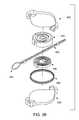
- FIG. 3Adepicts an exemplary recoil mechanism for recoiling tethers of the lighting fixture.
- FIG. 3Bdepicts an exploded view of the recoil mechanism of FIG. 3A .
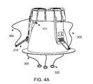
- FIG. 4A-4Cdepicts a method of installing the lighting fixture of FIG. 1 into a ceiling.
- the embodimentsaddress concerns associated with mounting a downlight lighting fixture into a recess in a ceiling or other substantially flat surface or sub-surface.
- the ceilingmay be associated with an office, a retail location, or similar environment.
- FIG. 1depicts a perspective side view of a lighting fixture using a bracket assembly in accordance with an exemplary embodiment of the present invention.
- the lighting fixture 100includes (i) a housing 120 enclosing electronics, such as an infusion module, (ii) lens components 130 , configured for emitting, diffusing, or otherwise passing light emitted by lights (e.g., LEDs), and (iii) a heat sink 170 to provide cooling for optics and other embedded electronics within the housing 120 .
- the lighting fixture 100further includes a bracket assembly 200 attached or otherwise affixed to a portion of the lighting fixture 100 , such as the heat sink 170 .
- the bracket assembly 200includes a tension mechanism, such as a spring clamp 210 (illustrated in FIG. 1 ) having a spring coil 220 and a spring arm 240 .
- a tension mechanismsuch as a spring clamp 210 (illustrated in FIG. 1 ) having a spring coil 220 and a spring arm 240 .
- the spring coil 220In a minimal tension position, the spring coil 220 has a preset amount of tension within its coil windings.
- the spring arm 240is moved from the minimal tension position to a maximum tension position that produces additional tension greater than the preset tension in the spring coil 220 .
- the spring arm 240is raised from the minimal position to the maximum tension position, which creates additional tension in the spring coil 220 .
- a plurality of spring clamps 210are positioned around the circumference of the housing 120 .
- Multiple spring clamps 210allow installation of larger and heavier downlight fixtures within ceiling recesses for example. With hands alone, it would be difficult for installers to engage three or spring clamps 210 at one time to install or uninstall the lighting fixture 100 .
- Other suitable configurationsare spring available, such as but not limited to machined springs and flat springs, as understood by those of skill in the art, and would be within the spirit and scope of the present invention.
- the housing 120includes one or more openings 127 (illustrated in FIG. 1 ) to allow passage of a tether 300 described in detail below, from the exterior of the housing 120 , through one or more openings 125 (illustrated in FIG. 2 ) in the interior of the housing 120 .
- the openings 125 , 127allow the tether 300 to pass from location not easily accessed by an installer/uninstaller when the lighting fixture 100 is mounted to a location easily accessed after mounting.
- the opening 125allows the tether to attach to the spring clamp 210 that is positioned within a ceiling 102 after installation of the lighting fixture 100 .
- the tether 300simplifies installation of the lighting fixture 100 by eliminating the need for a user to holding springs, or mounting clamps, under tension while inserting the lighting fixture 100 through a recess 110 .
- the tether 300is configured to temporarily position and secure the spring clamp 210 in the maximum tension position prior to installation of the lighting fixture 100 . In this manner, the risk of injury to an installer is substantially reduced. Additionally, risk of injury to the installer is reduced due to the deployment of the tether 300 by the installer/uninstaller at a location outside of the ceiling 102 .
- the tether 300is configured to rotate the spring clamp 210 about an axis of the spring coil 220 .
- the spring clamp 210is rotated from a minimal tension position prior to installation to a maximum tension position for installation and finally back to the minimum tension position after installation.
- tether 300is in a position where the material of the tether 300 is not tightened.
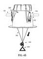
- the tether 300is tightened using a tool 500 (illustrated in FIG. 4B ) or other item used to pull any slack from within the material of the tether 300 .
- the tether 300returns to the loosened or non-tightened position.
- One or more tethers 300can be used at the same time or approximately simultaneously by the installers/uninstaller to place one or more spring clamps 210 in the maximum tension position.
- the tether 300may be composed of one or more materials configured to support the spring arm 240 when the spring coil 220 is placed under additional tension, causing the spring clamp 210 to be placed in the maximum tension position. Specifically, the tether 300 is composed of materials that allows movement for at least some flexibility and tension.
- the tether 300may be composed of one or more cords or string composed of plastic (e.g., nylon), metal (e.g., steel), or a combination thereof. The tether 300 may be subsequently added to the lighting fixture 100 in a post manufacturing operation.
- the tether 300is attached to a loop 260 or other securing feature on the spring clamp 210 , as illustrated in FIG. 1 .
- the loop 260may be attached or otherwise affixed to a position on the spring clamp 210 such as the spring arm 240 using conventional techniques, such as but not limited to welding.
- FIG. 2illustrates exemplary lens components 130 , including a diffuser 140 , a reflector 160 , and trim 180 .
- the tether 300passes from the exterior of the housing 120 through the interior of the housing 120 and exit at or within the area occupied by the lens components 130 .
- the tether 300exits at an area near the diffuser 140 or the reflector 160 through pre-drilled holes.
- Each tether 300is fed into the inside of the reflector 160 where the installer/uninstaller will be able to access all tethers 300 at same time.
- the tether 300remains on the exterior of the housing 120 (e.g., away from the electronic components), and exit at a location approximate to the trim 180 .
- the tether 300includes a hook or stopper 320 , as illustrated in FIG. 2 .
- the stopper 320may be affixed or subsequently to the tether 300 .
- the stopper 320serves to prevent the tether 300 from being pushed too far into the interior of the housing 120 , which may be out of reach of the installer/uninstaller.
- the stopper 320also serves to temporarily attach or secure each tether 300 to the tool 500 or other object to promote generally simultaneously positioning of the spring clamps 210 in the maximum tension position and releasing the spring clamps 210 to the minimum tension position.
- FIG. 3Adepicts a recoil mechanism 400 for retracting the tethers 300 .
- the tethers 300are retracted or otherwise stored to prevent the tethers 300 from obstructing the lens components 130 .
- the recoil mechanism 400may be configured such that both ends of the tether 300 can be pulled out of the recoil mechanism 400 for use and stored within the recoil mechanism 400 for when not in use.
- the recoil mechanism 400may be positioned on the exterior of the housing 120 (e.g., near the opening 127 ). In other embodiments, the recoil mechanism 400 is positioned on the interior of the housing 120 , not visible to the installer/uninstaller. In yet other embodiments, the recoil mechanism 400 may be positioned visible to the installer/uninstaller near the lens components 130 of the lighting fixture 100 (e.g., near the opening 125 ).
- FIG. 3Bdepicts and exploded view the recoil mechanism 400 including a casing 420 that houses internal components such as, a turntable 440 , a torsion spring 460 , and a retaining base 480 .
- the recoil mechanism 400may contain additional components such as screws, pins or other devices which are used to secure the casing 420 around the internal components.
- the retaining base 480includes the turntable 440 which are both coupled to the casing 420 , for example using an axle pole positioned on the casing 420 .
- the turntable 440may include a positioning hole pivotally configured to couple to the casing 420 , using the axle pole.
- the turntable 440may include at least one groove on the periphery of the turntable 440 configured to position the tether 300 within the turntable 440 .
- the turntable 440also includes the torsion spring 460 having a latch end located at an inner side of the torsion spring 460 .
- the torsion spring 460allows the tether 300 to be passed into the groove(s) of the turntable 440 , such that both ends of the tether 300 can be pulled out.
- the latch endis configured to couple to the casing 420 , for example using the axle pole.
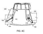
- FIGS. 4A-4Cillustrate exemplary stages occurring during installation of the lighting fixture 100 through the recess 110 using the tethers 300 .
- the spring clamps 210begin in the minimum tension position and the tethers 300 are in the non-tightened (loosened) position.
- the lighting fixture 100is ready for installation when the spring clamps 210 are in the maximum tension position.
- the spring clamps 210are placed in the maximum tension positions by tightening the tethers 300 in a direction as illustrated by the arrow as illustrated in FIG. 4B .
- the tethers 300may be tightened using the tool 500 or other item used to pull any slack from within the material of tether 300 .
- the lighting fixture 100is positioned to be received by the recess 110 of the ceiling 102 .
- the heat sink 170 and the housing 120are positioned to pass through the recess 110 .
- the tethers 300are tightened, using the tool 500 or otherwise, to position the spring clamps 210 in the maximum tension position. Once the spring clamps 210 are in the maximum tension position, the lighting fixture 100 can be moved out of the recess 110 . Once removed, the tethers 300 are be loosed, allowing the spring clamps 210 to return to the minimum tension position. The tethers 300 can subsequently be stored (e.g., using the recoil mechanism 400 ) for future use.
Landscapes
- Engineering & Computer Science (AREA)
- General Engineering & Computer Science (AREA)
- Non-Portable Lighting Devices Or Systems Thereof (AREA)
Abstract
Description
Claims (22)
Priority Applications (2)
| Application Number | Priority Date | Filing Date | Title |
|---|---|---|---|
| US14/882,664US9933143B2 (en) | 2015-07-07 | 2015-10-14 | Engagement system and method for mounting lighting fixture |
| EP16177855.0AEP3115686A1 (en) | 2015-07-07 | 2016-07-04 | Engagement system and method for mounting lighting fixture |
Applications Claiming Priority (2)
| Application Number | Priority Date | Filing Date | Title |
|---|---|---|---|
| US201562189438P | 2015-07-07 | 2015-07-07 | |
| US14/882,664US9933143B2 (en) | 2015-07-07 | 2015-10-14 | Engagement system and method for mounting lighting fixture |
Publications (2)
| Publication Number | Publication Date |
|---|---|
| US20170009964A1 US20170009964A1 (en) | 2017-01-12 |
| US9933143B2true US9933143B2 (en) | 2018-04-03 |
Family
ID=56740788
Family Applications (1)
| Application Number | Title | Priority Date | Filing Date |
|---|---|---|---|
| US14/882,664Expired - Fee RelatedUS9933143B2 (en) | 2015-07-07 | 2015-10-14 | Engagement system and method for mounting lighting fixture |
Country Status (2)
| Country | Link |
|---|---|
| US (1) | US9933143B2 (en) |
| EP (1) | EP3115686A1 (en) |
Families Citing this family (5)
| Publication number | Priority date | Publication date | Assignee | Title |
|---|---|---|---|---|
| CN108253355B (en)* | 2018-01-08 | 2020-06-23 | 江门市引球照明电器有限公司 | Combined LED lamp |
| US10724717B2 (en)* | 2018-11-08 | 2020-07-28 | Abl Ip Holding Llc | Light fixture installation apparatus and methods |
| US10955118B2 (en) | 2018-11-08 | 2021-03-23 | Abl Ip Holding Llc | Light fixture installation apparatus and methods |
| US10801681B1 (en)* | 2020-03-12 | 2020-10-13 | Globe Electric Company Inc. | Recessed light fixture assembly with interchangeable trim collar |
| WO2022057877A1 (en)* | 2020-09-18 | 2022-03-24 | 苏州欧普照明有限公司 | Lamp body, lighting lamp, and assembling method for lighting lamp |
Citations (28)
| Publication number | Priority date | Publication date | Assignee | Title |
|---|---|---|---|---|
| AU411004B2 (en) | 1969-05-21 | 1971-03-05 | Greendale Engineering & Cables Pty. Limited | Improved support means for recessed light fittings |
| US3620401A (en)* | 1970-05-11 | 1971-11-16 | Markstone Mfg Co | Recessed lighting fixture including mounting clamp means |
| US4039822A (en) | 1976-05-05 | 1977-08-02 | Lightolier Incorporated | Circular recessed lighting fixture |
| US4088293A (en) | 1976-06-07 | 1978-05-09 | Erico Products, Inc. | Lay-in light fixture retainer clip |
| US4238815A (en)* | 1978-06-29 | 1980-12-09 | Edison Price, Incorporated | Recessed light fixture |
| JPS5745712U (en) | 1980-08-29 | 1982-03-13 | ||
| US4685037A (en) | 1984-11-29 | 1987-08-04 | Cooper Industries, Inc. | Spring loaded recessed lighting fixture thermal protection |
| US4956758A (en)* | 1989-04-10 | 1990-09-11 | Janice Industries | Lamp mounting apparatus and method |
| US5068772A (en) | 1990-08-30 | 1991-11-26 | Troy Lighting, Inc. | Recessed lighting fixture |
| US5122944A (en) | 1989-06-27 | 1992-06-16 | Thorn Emi Plc | Mounting arrangement for a lamp fitting |
| US5299952A (en)* | 1992-07-27 | 1994-04-05 | Hinds Jr Richard A | Overhead electrical fixture and portable lowering tool therefor |
| US5377088A (en) | 1993-03-03 | 1994-12-27 | Lecluze; Michel | Light fixture for mounting to a ceiling, wall or the like |
| WO1996018068A1 (en) | 1994-12-09 | 1996-06-13 | Zumtobel Licht Gmbh | Recessed light fitting |
| US5567041A (en) | 1995-08-14 | 1996-10-22 | Slocum; Karl | Self supporting recessed ceiling fixture |
| JP2870636B1 (en) | 1998-02-05 | 1999-03-17 | 大光電機株式会社 | Mounting equipment for ceiling-mounted lighting fixtures |
| US5964523A (en) | 1997-04-11 | 1999-10-12 | Erco Leuchten Gmbh | Remodel recessed light fixture |
| US6000818A (en) | 1998-10-19 | 1999-12-14 | Canlyte Inc. | Mounting clip for a recessed light fixture |
| US20050207146A1 (en) | 2004-03-18 | 2005-09-22 | Reggiani S.P.A. Illuminazione | Supporting device for a lighting appliance |
| DE102007036979A1 (en) | 2007-05-03 | 2008-11-06 | Zumtobel Lighting Gmbh | Fastening element for a recessed luminaire |
| US7494254B2 (en)* | 2006-02-14 | 2009-02-24 | Rogers Elizabeth M | Pull down light fixture |
| US20100039829A1 (en) | 2008-08-12 | 2010-02-18 | Ge Investment Co., Ltd. | Light-emitting diode lamp |
| EP2314914A1 (en) | 2009-10-21 | 2011-04-27 | Zumtobel Lighting GmbH | Fitting device for a recessed luminaire |
| US20110180678A1 (en)* | 2010-01-26 | 2011-07-28 | Multistar Industries Co., Ltd. | Carrying device |
| US20110235342A1 (en) | 2010-03-24 | 2011-09-29 | Skynet Electronic Co., Ltd | Recessed lamp support structure |
| WO2012088721A1 (en) | 2010-12-31 | 2012-07-05 | Wu Liangju | Embedded ceiling lamp with radiating space |
| DE202013008171U1 (en) | 2012-09-22 | 2013-09-30 | Theben Ag | Holding device for ceiling mounting devices |
| US9052101B1 (en) | 2013-08-29 | 2015-06-09 | Cooper Technologies Company | Retrofit mounting device for open frame ceiling |
| US20170009963A1 (en) | 2015-07-07 | 2017-01-12 | GE Lighting Solutions, LLC | Engagement mechanism and method for mounting lighting fixture |
- 2015
- 2015-10-14USUS14/882,664patent/US9933143B2/ennot_activeExpired - Fee Related
- 2016
- 2016-07-04EPEP16177855.0Apatent/EP3115686A1/ennot_activeWithdrawn
Patent Citations (30)
| Publication number | Priority date | Publication date | Assignee | Title |
|---|---|---|---|---|
| AU411004B2 (en) | 1969-05-21 | 1971-03-05 | Greendale Engineering & Cables Pty. Limited | Improved support means for recessed light fittings |
| US3620401A (en)* | 1970-05-11 | 1971-11-16 | Markstone Mfg Co | Recessed lighting fixture including mounting clamp means |
| US4039822A (en) | 1976-05-05 | 1977-08-02 | Lightolier Incorporated | Circular recessed lighting fixture |
| US4088293A (en) | 1976-06-07 | 1978-05-09 | Erico Products, Inc. | Lay-in light fixture retainer clip |
| US4238815A (en)* | 1978-06-29 | 1980-12-09 | Edison Price, Incorporated | Recessed light fixture |
| JPS5745712U (en) | 1980-08-29 | 1982-03-13 | ||
| US4685037A (en) | 1984-11-29 | 1987-08-04 | Cooper Industries, Inc. | Spring loaded recessed lighting fixture thermal protection |
| US4956758A (en)* | 1989-04-10 | 1990-09-11 | Janice Industries | Lamp mounting apparatus and method |
| US5122944A (en) | 1989-06-27 | 1992-06-16 | Thorn Emi Plc | Mounting arrangement for a lamp fitting |
| US5068772A (en) | 1990-08-30 | 1991-11-26 | Troy Lighting, Inc. | Recessed lighting fixture |
| US5299952A (en)* | 1992-07-27 | 1994-04-05 | Hinds Jr Richard A | Overhead electrical fixture and portable lowering tool therefor |
| US5377088A (en) | 1993-03-03 | 1994-12-27 | Lecluze; Michel | Light fixture for mounting to a ceiling, wall or the like |
| WO1996018068A1 (en) | 1994-12-09 | 1996-06-13 | Zumtobel Licht Gmbh | Recessed light fitting |
| US5567041A (en) | 1995-08-14 | 1996-10-22 | Slocum; Karl | Self supporting recessed ceiling fixture |
| US5964523A (en) | 1997-04-11 | 1999-10-12 | Erco Leuchten Gmbh | Remodel recessed light fixture |
| JP2870636B1 (en) | 1998-02-05 | 1999-03-17 | 大光電機株式会社 | Mounting equipment for ceiling-mounted lighting fixtures |
| US6000818A (en) | 1998-10-19 | 1999-12-14 | Canlyte Inc. | Mounting clip for a recessed light fixture |
| US20050207146A1 (en) | 2004-03-18 | 2005-09-22 | Reggiani S.P.A. Illuminazione | Supporting device for a lighting appliance |
| US7494254B2 (en)* | 2006-02-14 | 2009-02-24 | Rogers Elizabeth M | Pull down light fixture |
| DE102007036979A1 (en) | 2007-05-03 | 2008-11-06 | Zumtobel Lighting Gmbh | Fastening element for a recessed luminaire |
| WO2008135126A1 (en) | 2007-05-03 | 2008-11-13 | Zumtobel Lighting Gmbh | Mounting element for a built-in light |
| EP2140197A1 (en) | 2007-05-03 | 2010-01-06 | Zumtobel Lighting GMBH | Mounting element for a built-in light |
| US20100039829A1 (en) | 2008-08-12 | 2010-02-18 | Ge Investment Co., Ltd. | Light-emitting diode lamp |
| EP2314914A1 (en) | 2009-10-21 | 2011-04-27 | Zumtobel Lighting GmbH | Fitting device for a recessed luminaire |
| US20110180678A1 (en)* | 2010-01-26 | 2011-07-28 | Multistar Industries Co., Ltd. | Carrying device |
| US20110235342A1 (en) | 2010-03-24 | 2011-09-29 | Skynet Electronic Co., Ltd | Recessed lamp support structure |
| WO2012088721A1 (en) | 2010-12-31 | 2012-07-05 | Wu Liangju | Embedded ceiling lamp with radiating space |
| DE202013008171U1 (en) | 2012-09-22 | 2013-09-30 | Theben Ag | Holding device for ceiling mounting devices |
| US9052101B1 (en) | 2013-08-29 | 2015-06-09 | Cooper Technologies Company | Retrofit mounting device for open frame ceiling |
| US20170009963A1 (en) | 2015-07-07 | 2017-01-12 | GE Lighting Solutions, LLC | Engagement mechanism and method for mounting lighting fixture |
Non-Patent Citations (6)
| Title |
|---|
| Extended European Search Report and Opinion issued in connection with corresponding EP Application No. 16177855.0 dated Nov. 3, 2016. |
| Extended European Search Report and Opinion issued in connection with related EP Application No. 15167640.0 dated Jul. 20, 2015. |
| http://www.youtube.com/watch?v=Tob89ByGhL4. |
| Non-Final Rejection towards U.S. Appl. No. 14/278,897 dated Aug. 5, 2016. |
| Notice of Allowance towards U.S. Appl. No. 14/278,897 dated Jan. 31, 2017. |
| WO 1996-018068 , Jun. 1996, Kempter et al, English Translation.* |
Also Published As
| Publication number | Publication date |
|---|---|
| EP3115686A1 (en) | 2017-01-11 |
| US20170009964A1 (en) | 2017-01-12 |
Similar Documents
| Publication | Publication Date | Title |
|---|---|---|
| US9933143B2 (en) | Engagement system and method for mounting lighting fixture | |
| US6336613B1 (en) | Adjustable lighting reflector bracket | |
| US20110023401A1 (en) | Strut system | |
| US7549780B2 (en) | Recessed lighting fixture | |
| US7673842B2 (en) | Captive retaining spring | |
| US9933144B2 (en) | Light fixture mounting assembly | |
| US9557022B2 (en) | Non-round retrofit recessed LED lighting fixture | |
| US8783896B2 (en) | Pivotable rail assembly for installing recessed lighting fixtures | |
| US9506611B2 (en) | Recessed luminaire with shuttle mechanism for access to electrical components | |
| US9689564B2 (en) | System to allocate luminance | |
| RU2512061C2 (en) | Elongated lighting fixture and method of its fixing to surface | |
| US10520169B2 (en) | Snap in retrofit panel | |
| EP3500793B1 (en) | Retrofit led light panel | |
| US20140140075A1 (en) | Downlight support | |
| JP5665960B2 (en) | Clip connection structure | |
| US10018336B2 (en) | Engagement mechanism and method for mounting lighting fixture | |
| US10782001B2 (en) | Light engine retrofit kit for existing light fixtures and associated method | |
| WO2017144304A1 (en) | Troffer retrofitting | |
| US20180058668A1 (en) | Captive retaining spring | |
| RU101776U1 (en) | Recessed luminaire | |
| JP2017533561A (en) | Device and method for surface mounting of electrical devices | |
| JP7697669B2 (en) | Lighting equipment | |
| KR101663052B1 (en) | LED ceiling lights | |
| JP2014157682A (en) | Lamp device and lighting device | |
| JP2015220095A (en) | Cable holder for lighting case |
Legal Events
| Date | Code | Title | Description |
|---|---|---|---|
| AS | Assignment | Owner name:GE LIGHTING SOLUTIONS, LLC, OHIO Free format text:ASSIGNMENT OF ASSIGNORS INTEREST;ASSIGNOR:CHANCEY, JOHN EDWARD;REEL/FRAME:036789/0492 Effective date:20150930 | |
| STCF | Information on status: patent grant | Free format text:PATENTED CASE | |
| AS | Assignment | Owner name:CURRENT LIGHTING SOLUTIONS, LLC, OHIO Free format text:CHANGE OF NAME;ASSIGNOR:GE LIGHTING SOLUTIONS, LLC;REEL/FRAME:048830/0564 Effective date:20190401 | |
| FEPP | Fee payment procedure | Free format text:MAINTENANCE FEE REMINDER MAILED (ORIGINAL EVENT CODE: REM.); ENTITY STATUS OF PATENT OWNER: LARGE ENTITY | |
| AS | Assignment | Owner name:ALLY BANK, AS COLLATERAL AGENT, NEW YORK Free format text:SECURITY AGREEMENT;ASSIGNORS:HUBBELL LIGHTING, INC.;LITECONTROL CORPORATION;CURRENT LIGHTING SOLUTIONS, LLC;AND OTHERS;REEL/FRAME:058982/0844 Effective date:20220201 | |
| AS | Assignment | Owner name:ATLANTIC PARK STRATEGIC CAPITAL FUND, L.P., AS COLLATERAL AGENT, NEW YORK Free format text:SECURITY INTEREST;ASSIGNORS:HUBBELL LIGHTING, INC.;LITECONTROL CORPORATION;CURRENT LIGHTING SOLUTIONS, LLC;AND OTHERS;REEL/FRAME:059034/0469 Effective date:20220201 | |
| LAPS | Lapse for failure to pay maintenance fees | Free format text:PATENT EXPIRED FOR FAILURE TO PAY MAINTENANCE FEES (ORIGINAL EVENT CODE: EXP.); ENTITY STATUS OF PATENT OWNER: LARGE ENTITY | |
| STCH | Information on status: patent discontinuation | Free format text:PATENT EXPIRED DUE TO NONPAYMENT OF MAINTENANCE FEES UNDER 37 CFR 1.362 | |
| FP | Lapsed due to failure to pay maintenance fee | Effective date:20220403 | |
| AS | Assignment | Owner name:ALLY BANK, AS COLLATERAL AGENT, NEW YORK Free format text:CORRECTIVE ASSIGNMENT TO CORRECT THE PATENT NUMBER 10841994 TO PATENT NUMBER 11570872 PREVIOUSLY RECORDED ON REEL 058982 FRAME 0844. ASSIGNOR(S) HEREBY CONFIRMS THE SECURITY AGREEMENT;ASSIGNORS:HUBBELL LIGHTING, INC.;LITECONTROL CORPORATION;CURRENT LIGHTING SOLUTIONS, LLC;AND OTHERS;REEL/FRAME:066355/0455 Effective date:20220201 | |
| AS | Assignment | Owner name:ATLANTIC PARK STRATEGIC CAPITAL FUND, L.P., AS COLLATERAL AGENT, NEW YORK Free format text:CORRECTIVE ASSIGNMENT TO CORRECT THE PATENT NUMBER PREVIOUSLY RECORDED AT REEL: 059034 FRAME: 0469. ASSIGNOR(S) HEREBY CONFIRMS THE SECURITY INTEREST;ASSIGNORS:HUBBELL LIGHTING, INC.;LITECONTROL CORPORATION;CURRENT LIGHTING SOLUTIONS, LLC;AND OTHERS;REEL/FRAME:066372/0590 Effective date:20220201 |