US9933054B2 - Continuously variable transmission and an infinitely variable transmission variator drive - Google Patents
Continuously variable transmission and an infinitely variable transmission variator driveDownload PDFInfo
- Publication number
- US9933054B2 US9933054B2US15/380,043US201615380043AUS9933054B2US 9933054 B2US9933054 B2US 9933054B2US 201615380043 AUS201615380043 AUS 201615380043AUS 9933054 B2US9933054 B2US 9933054B2
- Authority
- US
- United States
- Prior art keywords
- clutch
- variable transmission
- ring assembly
- variator
- grounding
- Prior art date
- Legal status (The legal status is an assumption and is not a legal conclusion. Google has not performed a legal analysis and makes no representation as to the accuracy of the status listed.)
- Expired - Fee Related
Links
- 230000005540biological transmissionEffects0.000titleclaimsabstractdescription145
- 230000001419dependent effectEffects0.000claimsdescription5
- 239000012530fluidSubstances0.000claimsdescription2
- 238000000034methodMethods0.000abstractdescription9
- 230000007246mechanismEffects0.000description17
- 230000007935neutral effectEffects0.000description4
- 230000008901benefitEffects0.000description2
- 230000002706hydrostatic effectEffects0.000description1
- 238000010348incorporationMethods0.000description1
- 239000000314lubricantSubstances0.000description1
- 239000007787solidSubstances0.000description1
- 238000006467substitution reactionMethods0.000description1
Images


Classifications
- F—MECHANICAL ENGINEERING; LIGHTING; HEATING; WEAPONS; BLASTING
- F16—ENGINEERING ELEMENTS AND UNITS; GENERAL MEASURES FOR PRODUCING AND MAINTAINING EFFECTIVE FUNCTIONING OF MACHINES OR INSTALLATIONS; THERMAL INSULATION IN GENERAL
- F16H—GEARING
- F16H15/00—Gearings for conveying rotary motion with variable gear ratio, or for reversing rotary motion, by friction between rotary members
- F16H15/48—Gearings for conveying rotary motion with variable gear ratio, or for reversing rotary motion, by friction between rotary members with members having orbital motion
- F16H15/50—Gearings providing a continuous range of gear ratios
- F16H15/52—Gearings providing a continuous range of gear ratios in which a member of uniform effective diameter mounted on a shaft may co-operate with different parts of another member
- F—MECHANICAL ENGINEERING; LIGHTING; HEATING; WEAPONS; BLASTING
- F16—ENGINEERING ELEMENTS AND UNITS; GENERAL MEASURES FOR PRODUCING AND MAINTAINING EFFECTIVE FUNCTIONING OF MACHINES OR INSTALLATIONS; THERMAL INSULATION IN GENERAL
- F16H—GEARING
- F16H37/00—Combinations of mechanical gearings, not provided for in groups F16H1/00 - F16H35/00
- F16H37/02—Combinations of mechanical gearings, not provided for in groups F16H1/00 - F16H35/00 comprising essentially only toothed or friction gearings
- F16H37/06—Combinations of mechanical gearings, not provided for in groups F16H1/00 - F16H35/00 comprising essentially only toothed or friction gearings with a plurality of driving or driven shafts; with arrangements for dividing torque between two or more intermediate shafts
- F16H37/08—Combinations of mechanical gearings, not provided for in groups F16H1/00 - F16H35/00 comprising essentially only toothed or friction gearings with a plurality of driving or driven shafts; with arrangements for dividing torque between two or more intermediate shafts with differential gearing
- F16H37/0833—Combinations of mechanical gearings, not provided for in groups F16H1/00 - F16H35/00 comprising essentially only toothed or friction gearings with a plurality of driving or driven shafts; with arrangements for dividing torque between two or more intermediate shafts with differential gearing with arrangements for dividing torque between two or more intermediate shafts, i.e. with two or more internal power paths
- F16H37/084—Combinations of mechanical gearings, not provided for in groups F16H1/00 - F16H35/00 comprising essentially only toothed or friction gearings with a plurality of driving or driven shafts; with arrangements for dividing torque between two or more intermediate shafts with differential gearing with arrangements for dividing torque between two or more intermediate shafts, i.e. with two or more internal power paths at least one power path being a continuously variable transmission, i.e. CVT
- F16H37/086—CVT using two coaxial friction members cooperating with at least one intermediate friction member
- F—MECHANICAL ENGINEERING; LIGHTING; HEATING; WEAPONS; BLASTING
- F16—ENGINEERING ELEMENTS AND UNITS; GENERAL MEASURES FOR PRODUCING AND MAINTAINING EFFECTIVE FUNCTIONING OF MACHINES OR INSTALLATIONS; THERMAL INSULATION IN GENERAL
- F16H—GEARING
- F16H37/00—Combinations of mechanical gearings, not provided for in groups F16H1/00 - F16H35/00
- F16H37/02—Combinations of mechanical gearings, not provided for in groups F16H1/00 - F16H35/00 comprising essentially only toothed or friction gearings
- F16H37/06—Combinations of mechanical gearings, not provided for in groups F16H1/00 - F16H35/00 comprising essentially only toothed or friction gearings with a plurality of driving or driven shafts; with arrangements for dividing torque between two or more intermediate shafts
- F16H37/08—Combinations of mechanical gearings, not provided for in groups F16H1/00 - F16H35/00 comprising essentially only toothed or friction gearings with a plurality of driving or driven shafts; with arrangements for dividing torque between two or more intermediate shafts with differential gearing
- F16H37/0833—Combinations of mechanical gearings, not provided for in groups F16H1/00 - F16H35/00 comprising essentially only toothed or friction gearings with a plurality of driving or driven shafts; with arrangements for dividing torque between two or more intermediate shafts with differential gearing with arrangements for dividing torque between two or more intermediate shafts, i.e. with two or more internal power paths
- F16H37/084—Combinations of mechanical gearings, not provided for in groups F16H1/00 - F16H35/00 comprising essentially only toothed or friction gearings with a plurality of driving or driven shafts; with arrangements for dividing torque between two or more intermediate shafts with differential gearing with arrangements for dividing torque between two or more intermediate shafts, i.e. with two or more internal power paths at least one power path being a continuously variable transmission, i.e. CVT
- F16H2037/0866—Power-split transmissions with distributing differentials, with the output of the CVT connected or connectable to the output shaft
- F—MECHANICAL ENGINEERING; LIGHTING; HEATING; WEAPONS; BLASTING
- F16—ENGINEERING ELEMENTS AND UNITS; GENERAL MEASURES FOR PRODUCING AND MAINTAINING EFFECTIVE FUNCTIONING OF MACHINES OR INSTALLATIONS; THERMAL INSULATION IN GENERAL
- F16H—GEARING
- F16H2200/00—Transmissions for multiple ratios
- F16H2200/20—Transmissions using gears with orbital motion
- F16H2200/2002—Transmissions using gears with orbital motion characterised by the number of sets of orbital gears
- F16H2200/2005—Transmissions using gears with orbital motion characterised by the number of sets of orbital gears with one sets of orbital gears
- F—MECHANICAL ENGINEERING; LIGHTING; HEATING; WEAPONS; BLASTING
- F16—ENGINEERING ELEMENTS AND UNITS; GENERAL MEASURES FOR PRODUCING AND MAINTAINING EFFECTIVE FUNCTIONING OF MACHINES OR INSTALLATIONS; THERMAL INSULATION IN GENERAL
- F16H—GEARING
- F16H2200/00—Transmissions for multiple ratios
- F16H2200/20—Transmissions using gears with orbital motion
- F16H2200/203—Transmissions using gears with orbital motion characterised by the engaging friction means not of the freewheel type, e.g. friction clutches or brakes
- F16H2200/2035—Transmissions using gears with orbital motion characterised by the engaging friction means not of the freewheel type, e.g. friction clutches or brakes with two engaging means
Definitions
- a vehicle having a driveline including a continuously variable transmissionallows an operator of the vehicle or a control system of the vehicle to vary a drive ratio in a stepless manner, permitting a power source of the vehicle to operate at its most efficient rotational speed.
- the continuously variable transmissionmay be configured to be an infinitely variable transmission, wherein the vehicle can be steplessly shifted from a forward mode to a neutral mode or even to a reverse mode.
- Continuously variable transmissions known in the arttend to have limited ratio ranges and typically require the use of a torque convertor or a separate clutching mechanism to facilitate stopping and starting the vehicle.
- a transmission having a variator drivecapable of being placed in a continuously variable operating mode or an infinitely variable operating mode, capable of having a wide ratio range, and capable of integrating a clutching capability within the transmission.
- the ratio range resulting from the configurations described herein, or obvious to one of skill in the art having read such disclosurewill be wider than the variator range and sufficient for a vehicle.
- variable transmissioncomprising: an input shaft; an output shaft; and a first ring assembly rotatably disposed in a housing selectively drivingly engaged with the input shaft using a clutch, the first ring assembly configured to be prevented from rotating relative to the housing by a grounding clutch and the first ring assembly comprising a first variator ball engagement surface that is in driving engagement with a plurality of variator balls.
- the variable transmissionin certain embodiments, further comprises a variator carrier assembly rotatably disposed in the housing and drivingly engaged with the input shaft using a sun gear on the input shaft, a plurality of planet gears rotatably disposed in the variator carrier assembly, and a fixed ring gear coupled to the housing, the variator carrier assembly comprising an annular arrangement of the plurality of tiltable variator balls each having ball axle shafts.
- the variable transmissionin certain embodiments, further comprises a second ring assembly rotatably disposed in the housing drivingly engaged with the output shaft, the second ring assembly comprising a second variator ball engagement surface that is in driving engagement with each of the variator balls.
- the variable transmissionin certain embodiments, has an infinitely variable operating mode and a continuously variable operating mode.
- the input shaft and the output shaftare at least partially disposed in the housing.
- the input shaftis drivingly engaged with a torsional dampener disposed between an engine and the variable transmission.
- a first middle portion of the input shaftis selectively drivingly engaged with the first ring assembly. In some embodiments, a second middle portion of the input shaft is selectively drivingly engaged with the variator carrier assembly. In some embodiments, a second middle portion of the input shaft forms the sun gear and is drivingly engaged with the variator carrier assembly.
- the input shaftis drivingly engaged with a pump.
- the clutchcomprises a wet plate clutch, a dry plate clutch, a cone clutch, or any other clutch type that may be variably engaged.
- the variator carrier assemblycomprises a brake clutch which is configured to place the variable transmission in a parking condition.
- the plurality of planet gearsare drivingly engaged with the sun gear formed on the input shaft and with the fixed ring gear coupled to the housing.
- the first ring assemblycomprises a clutch engagement portion. In some embodiments, the clutch engagement portion extends inwardly from an inner surface of the first ring assembly. In some embodiments, the first ring assembly comprises a grounding clutch engagement portion. In some embodiments, the grounding clutch engagement portion extends outwardly from a surface of the first ring assembly. In some embodiments, the grounding clutch engagement portion extends outwardly from an outer surface of the first ring assembly. In some embodiments, the grounding clutch is at least partially disposed on an inner surface of the housing. In some embodiments, the grounding clutch is selectively variably engaged to militate against a relative rotation from occurring between the first ring assembly and the housing.
- an output gear formed on an outer surface of the second ring assemblyis in driving engagement with a first end of the output shaft.
- the output shaftcomprises a first end drivingly engaged with second ring assembly through a first output shaft gear formed in the output shaft.
- the output shaftcomprises a second end drivingly engaged with a vehicle output through a second output shaft gear formed in the output shaft.
- the first output shaft gear and the second output shaft gearhave differing diameters to adjust a drive ratio between the second ring assembly and the vehicle output.
- the infinitely variable operating modeexists when the clutch is placed in a disengaged position, and the grounding clutch is placed in an engaged position.
- the continuously variable operating modeexists when the clutch is placed in an engaged position, and the grounding clutch is placed in a disengaged position.
- the first ring assembly and the variator carrier assemblyrotate in similar directions but at differing rates.
- a mode of the transmissiondepends on the engagement status of the clutch and the grounding clutch.
- variable transmissioncomprising: an input shaft and a first ring assembly rotatably disposed in a housing, the first ring assembly drivingly engaged with the input shaft using a plurality of double planet gears rotatably disposed on the first ring assembly, the first ring assembly configured to be prevented from rotating relative to the housing by a second grounding clutch, and the first ring assembly comprising a first variator ball engagement surface that is in driving engagement with a plurality of tiltable variator balls.
- the variable transmission of some embodimentscomprises a variator carrier assembly rotatably disposed in the housing and configured to be militated from rotating relative to the housing by a first grounding clutch, the variator carrier assembly comprising a drive shaft drivingly engaged using a second sun gear engaged with a second gear of each of the double planet gears, and an annular arrangement of the plurality of tiltable variator balls each having ball axle shafts.
- the variable transmission of some embodimentscomprises a second ring assembly rotatably disposed in the housing drivingly engaged with a vehicle output, the second ring assembly comprising and a second variator ball engagement surface that is in driving engagement with each of the variator balls.
- said transmissionhas an infinitely variable operating mode and a continuously variable operating mode.
- the input shaftis at least partially disposed in the housing.
- the input shaftis drivingly engaged with a torsional dampener disposed between an engine and the variable transmission.
- a first sun gearis formed on a second end of the input shaft and is drivingly engaged with a first gear of each of the double planet gears.
- the first sun gear, the plurality of double planet gears, and the drive shaftform a ringless planetary gearset.
- the first ring assembly driven by the plurality of double planet gears when the variator carrier assembly is fixedis driven when the input shaft is rotated. In some embodiments, the variator carrier assembly driven by the plurality of double planet gears when the first ring assembly is fixed is driven when the input shaft is rotated.
- the variator carrier assemblycomprises a first grounding clutch engagement portion that forms of the first grounding clutch.
- the first grounding clutch engagement portionextends outwardly from a second end of the variator carrier assembly.
- the first grounding clutchis at least partially disposed on an inner surface of the housing.
- the first grounding clutchis configured to be selectively variably engaged to militate against a relative rotation from occurring between the variator carrier assembly and the housing.
- the first grounding clutchis a plate clutch.
- the first grounding clutchis a wet plate clutch, a dry plate clutch, a cone clutch, or any other clutch type that may be variably engaged.
- the first ring assemblyis selectively drivingly engaged with the input shaft using the first grounding clutch.
- the first ring assemblycomprises a second grounding clutch engagement portion.
- the second grounding clutch engagement portionextends outwardly from an outer surface of the first ring assembly.
- the second grounding clutchis at least partially disposed on an inner surface of the housing.
- the second grounding clutchmay be selectively variably engaged to militate against a relative rotation from occurring between the first ring assembly and the housing.
- the second grounding clutchis a plate clutch.
- the second grounding clutchis a wet plate clutch, a dry plate clutch, a cone clutch, or any other clutch type that may be variably engaged.
- the first variator carrier assemblymay be selectively drivingly engaged with the input shaft using the second grounding clutch.
- the second ring assemblycomprises an output gear formed in an outer surface of the second ring assembly.
- the output gearis in driving engagement with the vehicle output.
- an operating mode of the variable transmissionis dependent on an engagement status of the first grounding clutch and the second grounding clutch.
- the continuously variable operating modeis achieved when the first grounding clutch is engaged and the second grounding clutch is disengaged.
- the infinitely variable operating modeis achieved when the first grounding clutch is disengaged and the second grounding clutch is engaged
- variable transmissioncomprising: an input member; an output shaft; and a first ring assembly rotatably disposed in a housing, the first ring assembly selectively drivingly engaged with the input member using a first clutch, the first ring assembly configured to be prevented from rotating relative to the housing by a second grounding clutch, and the first ring assembly comprising a first variator ball engagement surface that is in driving engagement with a plurality of variator balls.
- variable transmissioncomprises a variator carrier assembly rotatably disposed in the housing and selectively drivingly engaged with the input member using a second clutch, the variator carrier assembly comprising a first grounding clutch engagement portion that selectively variably engages a portion of the first grounding clutch to mitigate against relative rotation between the first ring assembly and the housing, and an annular arrangement of the plurality of variator balls each having ball axle shafts.
- the variable transmissioncomprises a second ring assembly rotatably disposed in the housing drivingly engaged with the output shaft, the second ring assembly comprising and a second variator ball engagement surface that is in driving engagement with each of the variator balls.
- the variable transmissionhas an infinitely variable operating mode and a continuously variable operating mode.
- the input member and the output shaftare at least partially disposed in the housing.
- the input memberhas a first end drivingly engaged with a pump. In some embodiments, the input member is drivingly engaged with an engine. In some embodiments, the input member is drivingly engaged to the engine through at least one or more of a dampener and a pump. In some embodiments, the dampener is a torsional dampener.
- a second end inner surface of the input memberis selectively drivingly engaged with the first ring assembly using the first clutch.
- the first clutchis a wet plate clutch, a dry plate clutch, a cone clutch, or any other clutch type that may be variably engaged.
- the first ring assemblycomprises a first clutch engagement portion.
- the first clutch engagement portionextends outwardly from a distal end of the first ring assembly.
- the first clutch engagement portionis a portion of the first clutch.
- the first ring assemblycomprises a second grounding clutch engagement portion.
- the second grounding clutch engagement portionextends outwardly from a distal end of the first ring assembly.
- the second grounding clutch engagement portionis a portion of the second grounding clutch.
- the second grounding clutchis at least partially disposed on an inner surface of the housing. In some embodiments, the second grounding clutch is selectively variably engaged to militate against a relative rotation from occurring between the first ring assembly and the housing.
- a second end outer surface of the input memberis selectively drivingly engaged with the variator carrier assembly using the second clutch.
- the second clutchis a wet plate clutch, a dry plate clutch, a cone clutch, or any other clutch type that may be variably engaged.
- the variator carrier assemblycomprises a second clutch engagement portion.
- the second clutch engagement portionextends inwardly from an inner surface of the variator carrier assembly.
- the second clutch engagement portionis a portion of the second clutch. In some embodiments, when the second clutch is placed in an engaged position the variator carrier assembly is drivingly engaged with the input member.
- a distal end of the variator carrier assemblycomprises the first grounding clutch engagement portion.
- first grounding clutch engagement portionextends outwardly from an outer surface of the first ring assembly. In some embodiments, the first grounding clutch engagement portion forms a portion of the first grounding clutch.
- the second ring assemblycomprises an output gear formed in an outer surface thereof. In some embodiments, the second ring assembly is in driving engagement with a first end of the output shaft. In some embodiments, the output shaft comprises a first end drivingly engaged with the second ring assembly through a first gear formed in the output shaft and a second end drivingly engaged with the vehicle output through a second gear formed in the output shaft. In some embodiments, the first gear and the second gear have differing diameters to adjust a drive ratio between the second ring assembly and the vehicle output.
- an operating mode of the variable transmissionis dependent on an engagement status of the first clutch, the second clutch, the first grounding clutch, and the second grounding clutch.
- the continuously variable operating modeis achieved when the first clutch is placed in the engaged position, the second clutch is placed in a disengaged position, the first grounding clutch is placed in the engaged position, and the second grounding clutch is placed in a disengaged position.
- the first ring assemblywhen in the continuously variable operating mode, is drivingly engaged with the first ring assembly input shaft.
- each of the variator ballsrotate about their axis to transfer torque from the first ring assembly to the second ring assembly, and to a vehicle output through the output shaft.
- a drive ratio between the first ring assembly and the second ring assemblyis adjusted.
- the infinitely variable operating modeis achieved when the first clutch is placed in a disengaged position, the second clutch is placed in the engaged position, the first grounding clutch is placed in a disengaged position, and the second grounding clutch is placed in the engaged position.
- the variator carrier assemblywhen in the infinitely variable operating mode, is drivingly engaged with the first ring assembly input shaft and the first ring assembly is fixed with respect to the housing.
- a drive ratio between the variator carrier assembly and the second ring assemblyis adjusted to one of a forward operating mode, a powered neutral, and a reverse operating mode.
- variable transmissioncomprises an axial force generator configured to generate sufficient axial force to properly operate the vehicle transmission.
- the axial force generatorcomprises one or more clamping mechanisms.
- the axial force generatorcomprises a ball ramp.
- the axial force generatorcomprises a ball ramp thrust ring.
- the axial force generatorcomprises a load applied during assembly of the variable transmission.
- each of the ball axle shaftsis adjusted using a cam style tilting mechanism. In some embodiments, each of the ball axle shafts is adjusted using a split carrier axle skewing mechanism.
- the first variator ball engagement surfaceis formed in a distal end of the first ring assembly. In some embodiments, the first variator ball engagement surface is formed in an input ring of the first ring assembly. In some embodiments, the second variator ball engagement surface is formed in a distal end of the first ring assembly. In some embodiments, the first variator ball engagement surface is a conical surface or a concave toroidal surface in contact with or slightly spaced apart from each of the variator balls. In some embodiments, the second variator ball engagement surface is a conical surface or a concave toroidal surface in contact with or slightly spaced apart from each of the variator balls.
- the first variator ball engagement surfaceis in driving engagement with each of the variator balls through one of a boundary layer type friction and an elastohydrodynamic film.
- the second variator ball engagement surfaceis in driving engagement with each of the variator balls through one of a boundary layer type friction and an elastohydrodynamic film.
- variable transmissionof any arrangement disclosed herein or obvious to one of skill in the art upon reading the disclosure herein, wherein the variable transmission is disposed between an engine and a vehicle output.
- vehicle outputcomprises a differential and a drive axle.
- the vehicle drivelinecomprises a torsional dampener disposed between the engine and the variable transmission.
- the torsional dampenercomprises at least one torsional spring.
- a method of changing from between a continuously variable transmission mode, and an infinitely variable transmission modecomprising engaging or disengaging a clutch and a grounding clutch of the variable transmissions of any arrangement disclosed herein with reference to FIG. 1 or obvious to one of skill in the art upon reading the disclosure herein.
- a method of changing from between a continuously variable transmission mode, and an infinitely variable transmission modecomprising engaging or disengaging a first grounding clutch and a second grounding clutch of the variable transmissions of any arrangement disclosed herein with reference to FIG. 2 or obvious to one of skill in the art upon reading the disclosure herein.
- a method of changing from between a continuously variable transmission mode, and an infinitely variable transmission modecomprising engaging or disengaging first clutch, the second clutch, the first grounding clutch, and the second grounding clutch of the variable transmissions of any arrangement disclosed herein with reference to FIG. 3 or obvious to one of skill in the art upon reading the disclosure herein.
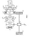
- FIG. 1depicts an embodiment of a vehicle driveline comprising a variable transmission including a planetary gearset located between an engine and a vehicle output.
- FIG. 2depicts an embodiment of a variable transmission including a plurality of double planet gears located between an engine and a vehicle output.
- FIG. 3depicts an embodiment of a variable transmission including two clutches and two grounding clutches located between an engine and a vehicle output.
- FIG. 4is a cutaway view of a currently known and used continuously variable transmission (CVT).
- CVTcontinuously variable transmission
- FIG. 5is a magnified cutaway view of a ball and ring of the CVT of FIG. 4 .
- a transmission having a variator drivecapable of being placed in a continuously variable operating mode or an infinitely variable operating mode, capable of having a wide ratio range, and capable of integrating a clutching capability within the transmission.
- the ratio range resulting from the configurations described herein, or obvious to one of skill in the art having read such disclosurewill be wider than the variator range and sufficient for a vehicle. Additional variable transmission details are described in U.S. application Ser. No. 13/743,951 filed Jan. 17, 2013, and/or PCT/US2013/026037 filed Feb. 14, 2013, incorporated herein by reference in their entirety.
- variable transmission 2 a , 2 b , 2 cmay be used to replace a conventional transmission and a clutch in a vehicle driveline.
- the variable transmission 2 a , 2 b , 2 cthat employ a ball type Continuously Variable Transmission (CVT, which is also known as CVP for constant variable planetary, herein) and may replace a conventional transmission and a clutch in a vehicle, such as a front wheel drive automobile.
- CVTContinuously Variable Transmission
- the transmissions disclosed hereinmay be used in any vehicle type that needs or uses a transmission.
- Such a CVTcomprises a number of balls, depending on the application, two discs with a conical surface contact with the balls, as input and output, and an idler as shown on FIG. 4 .
- the type of CVT provided hereincomprises a variator comprising a plurality of variator balls, depending on the application, two discs or annular rings 995 , 996 each having an engagement portion that engages the variator balls 997 , at least.
- the engagement portionsare optionally in a conical or toroidal convex or concave surface contact with the variator balls, as input ( 995 ) and output ( 996 ).
- the variatoroptionally includes an idler 999 contacting the balls as well as shown on FIG. 4 .
- the variator ballsare mounted on axles 998 , themselves held in a cage or carrier allowing captivating the ratio by tilting the variator balls' axes.
- the ballsare mounted on axes, themselves held in a cage or carrier allowing changing the ratio by tilting the ball's axes.
- Other types of ball CVTsalso exist, like the one produced by Milner but are slightly different.
- FIG. 5The working principle of such a CVT of FIG. 4 is shown on FIG. 5 .
- the CVPitself works with a traction fluid.
- the lubricant between the ball and the conical ringsacts as a solid at high pressure, transferring the power from the input ring, through the balls, to the output ring.
- the ratiocan be changed between input and output.
- the ratiois one, when the axis is tilted the distance between the axis and the contact point change, modifying the overall ratio. All the ball's axes are tilted at the same time with a mechanism included in the cage.
- the CVTis used to replace traditional transmission and is located between the engine and the differential, at least.
- the variable transmission 2 a , 2 b , 2 cis located between an engine 4 and a vehicle output 6 as shown in FIG. 1, 2 , or 3 .
- the vehicle output 6is a differential 54 and a drive axle; however, it is understood that other vehicle outputs may be used.
- the vehicle outputmay comprise bearings 12 a , 12 b , 12 c , 12 d , (not shown in FIG. 2 ) and wheels 24 a , 24 b of the vehicle.
- a torsional dampener 16(not shown in FIG. 1 or FIG. 2 ) may also be included, the torsional dampener 16 disposed between the engine 4 and the variable transmission 2 a , 2 b to reduce vibration and torque peaks.
- variable transmissioncomprising: an input shaft; an output shaft; and a first ring assembly rotatably disposed in a housing selectively drivingly engaged with the input shaft using a clutch, the first ring assembly configured to be prevented from rotating relative to the housing by a grounding clutch and the first ring assembly comprising a first variator ball engagement surface that is in driving engagement with a plurality of variator balls.
- the variable transmissionin certain embodiments, further comprises a variator carrier assembly rotatably disposed in the housing and drivingly engaged with the input shaft using a sun gear on the input shaft, a plurality of planet gears rotatably disposed in the variator carrier assembly, and a fixed ring gear coupled to the housing, the variator carrier assembly comprising an annular arrangement of the plurality of tiltable variator balls each having ball axle shafts.
- the variable transmissionin certain embodiments, further comprises a second ring assembly rotatably disposed in the housing drivingly engaged with the output shaft, the second ring assembly comprising a second variator ball engagement surface that is in driving engagement with each of the variator balls.
- the variable transmissionin certain embodiments, has an infinitely variable operating mode and a continuously variable operating mode.
- the input shaft and the output shaftare at least partially disposed in the housing.
- the input shaftis drivingly engaged with a torsional dampener disposed between an engine and the variable transmission.
- a first middle portion of the input shaftis selectively drivingly engaged with the first ring assembly. In some embodiments, a second middle portion of the input shaft is selectively drivingly engaged with the variator carrier assembly. In some embodiments, a second middle portion of the input shaft forms the sun gear and is drivingly engaged with the variator carrier assembly.
- the input shaftis drivingly engaged with a pump.
- the clutchcomprises a wet plate clutch, a dry plate clutch, a cone clutch, or any other clutch type that may be variably engaged.
- the variator carrier assemblycomprises a brake clutch which is configured to place the variable transmission in a parking condition.
- the plurality of planet gearsare drivingly engaged with the sun gear formed on the input shaft and with the fixed ring gear coupled to the housing.
- the first ring assemblycomprises a clutch engagement portion. In some embodiments, the clutch engagement portion extends inwardly from an inner surface of the first ring assembly. In some embodiments, the first ring assembly comprises a grounding clutch engagement portion. In some embodiments, the grounding clutch engagement portion extends outwardly from a surface of the first ring assembly. In some embodiments, the grounding clutch engagement portion extends outwardly from an outer surface of the first ring assembly. In some embodiments, the grounding clutch is at least partially disposed on an inner surface of the housing. In some embodiments, the grounding clutch is selectively variably engaged to militate against a relative rotation from occurring between the first ring assembly and the housing.
- an output gear formed on an outer surface of the second ring assemblyis in driving engagement with a first end of the output shaft.
- the output shaftcomprises a first end drivingly engaged with second ring assembly through a first output shaft gear formed in the output shaft.
- the output shaftcomprises a second end drivingly engaged with a vehicle output through a second output shaft gear formed in the output shaft.
- the first output shaft gear and the second output shaft gearhave differing diameters to adjust a drive ratio between the second ring assembly and the vehicle output.
- the infinitely variable operating modeexists when the clutch is placed in a disengaged position, and the grounding clutch is placed in an engaged position.
- the continuously variable operating modeexists when the clutch is placed in an engaged position, and the grounding clutch is placed in a disengaged position.
- the first ring assembly and the variator carrier assemblyrotate in similar directions but at differing rates.
- a mode of the transmissiondepends on the engagement status of the clutch and the grounding clutch.
- variable transmissioncomprising: an input shaft and a first ring assembly rotatably disposed in a housing, the first ring assembly drivingly engaged with the input shaft using a plurality of double planet gears rotatably disposed on the first ring assembly, the first ring assembly configured to be prevented from rotating relative to the housing by a second grounding clutch, and the first ring assembly comprising a first variator ball engagement surface that is in driving engagement with a plurality of tiltable variator balls.
- the variable transmission of some embodimentscomprises a variator carrier assembly rotatably disposed in the housing and configured to be militated from rotating relative to the housing by a first grounding clutch, the variator carrier assembly comprising a drive shaft drivingly engaged using a second sun gear engaged with a second gear of each of the double planet gears, and an annular arrangement of the plurality of tiltable variator balls each having ball axle shafts.
- the variable transmission of some embodimentscomprises a second ring assembly rotatably disposed in the housing drivingly engaged with a vehicle output, the second ring assembly comprising and a second variator ball engagement surface that is in driving engagement with each of the variator balls.
- said transmissionhas an infinitely variable operating mode and a continuously variable operating mode.
- the input shaftis at least partially disposed in the housing.
- the input shaftis drivingly engaged with a torsional dampener disposed between an engine and the variable transmission.
- a first sun gearis formed on a second end of the input shaft and is drivingly engaged with a first gear of each of the double planet gears.
- the first sun gear, the plurality of double planet gears, and the drive shaftform a ringless planetary gearset.
- the first ring assembly driven by the plurality of double planet gears when the variator carrier assembly is fixedis driven when the input shaft is rotated. In some embodiments, the variator carrier assembly driven by the plurality of double planet gears when the first ring assembly is fixed is driven when the input shaft is rotated.
- the variator carrier assemblycomprises a first grounding clutch engagement portion that forms of the first grounding clutch.
- the first grounding clutch engagement portionextends outwardly from a second end of the variator carrier assembly.
- the first grounding clutchis at least partially disposed on an inner surface of the housing.
- the first grounding clutchis configured to be selectively variably engaged to militate against a relative rotation from occurring between the variator carrier assembly and the housing.
- the first grounding clutchis a plate clutch.
- the first grounding clutchis a wet plate clutch, a dry plate clutch, a cone clutch, or any other clutch type that may be variably engaged.
- the first ring assemblyis selectively drivingly engaged with the input shaft using the first grounding clutch.
- the first ring assemblycomprises a second grounding clutch engagement portion.
- the second grounding clutch engagement portionextends outwardly from an outer surface of the first ring assembly.
- the second grounding clutchis at least partially disposed on an inner surface of the housing,
- the second grounding clutchmay be selectively variably engaged to militate against a relative rotation from occurring between the first ring assembly and the housing.
- the second grounding clutchis a plate clutch.
- the second grounding clutchis a wet plate clutch, a dry plate clutch, a cone clutch, or any other clutch type that may be variably engaged.
- the first variator carrier assemblymay be selectively drivingly engaged with the input shaft using the second grounding clutch.
- the second ring assemblycomprises an output gear formed in an outer surface of the second ring assembly.
- the output gearis in driving engagement with the vehicle output.
- an operating mode of the variable transmissionis dependent on an engagement status of the first grounding clutch and the second grounding clutch.
- the continuously variable operating modeis achieved when the first grounding clutch is engaged and the second grounding clutch is disengaged.
- the infinitely variable operating modeis achieved when the first grounding clutch is disengaged and the second grounding clutch is engaged.
- variable transmissioncomprising: an input member; an output shaft; and a first ring assembly rotatably disposed in a housing, the first ring assembly selectively drivingly engaged with the input member using a first clutch, the first ring assembly configured to be prevented from rotating relative to the housing by a second grounding clutch, and the first ring assembly comprising a first variator ball engagement surface that is in driving engagement with a plurality of variator balls.
- variable transmissioncomprises a variator carrier assembly rotatably disposed in the housing and selectively drivingly engaged with the input member using a second clutch, the variator carrier assembly comprising a first grounding clutch engagement portion that selectively variably engages a portion of the first grounding clutch to mitigate against relative rotation between the first ring assembly and the housing, and an annular arrangement of the plurality of variator balls each having ball axle shafts.
- the variable transmissioncomprises a second ring assembly rotatably disposed in the housing drivingly engaged with the output shaft, the second ring assembly comprising and a second variator ball engagement surface that is in driving engagement with each of the variator balls.
- the variable transmissionhas an infinitely variable operating mode and a continuously variable operating mode.
- the input member and the output shaftare at least partially disposed in the housing.
- the input memberhas a first end drivingly engaged with a pump. In some embodiments, the input member is drivingly engaged with an engine. In some embodiments, the input member is drivingly engaged to the engine through at least one or more of a dampener and a pump. In some embodiments, the dampener is a torsional dampener.
- a second end inner surface of the input memberis selectively drivingly engaged with the first ring assembly using the first clutch.
- the first clutchis a wet plate clutch, a dry plate clutch, a cone clutch, or any other clutch type that may be variably engaged.
- the first ring assemblycomprises a first clutch engagement portion.
- the first clutch engagement portionextends outwardly from a distal end of the first ring assembly.
- the first clutch engagement portionis a portion of the first clutch.
- the first ring assemblycomprises a second grounding clutch engagement portion.
- the second grounding clutch engagement portionextends outwardly from a distal end of the first ring assembly.
- the second grounding clutch engagement portionis a portion of the second grounding clutch.
- the second grounding clutchis at least partially disposed on an inner surface of the housing. In some embodiments, the second grounding clutch is selectively variably engaged to militate against a relative rotation from occurring between the first ring assembly and the housing.
- a second end outer surface of the input memberis selectively drivingly engaged with the variator carrier assembly using the second clutch.
- the second clutchis a wet plate clutch, a dry plate clutch, a cone clutch, or any other clutch type that may be variably engaged.
- the variator carrier assemblycomprises a second clutch engagement portion.
- the second clutch engagement portionextends inwardly from an inner surface of the variator carrier assembly.
- the second clutch engagement portionis a portion of the second clutch. In some embodiments, when the second clutch is placed in an engaged position the variator carrier assembly is drivingly engaged with the input member.
- a distal end of the variator carrier assemblycomprises the first grounding clutch engagement portion.
- first grounding clutch engagement portionextends outwardly from an outer surface of the first ring assembly. In some embodiments, the first grounding clutch engagement portion forms a portion of the first grounding clutch.
- the second ring assemblycomprises an output gear formed in an outer surface thereof. In some embodiments, the second ring assembly is in driving engagement with a first end of the output shaft. In some embodiments, the output shaft comprises a first end drivingly engaged with the second ring assembly through a first gear formed in the output shaft and a second end drivingly engaged with the vehicle output through a second gear formed in the output shaft. In some embodiments, the first gear and the second gear have differing diameters to adjust a drive ratio between the second ring assembly and the vehicle output.
- an operating mode of the variable transmissionis dependent on an engagement status of the first clutch, the second clutch, the first grounding clutch, and the second grounding clutch.
- the continuously variable operating modeis achieved when the first clutch is placed in the engaged position, the second clutch is placed in a disengaged position, the first grounding clutch is placed in the engaged position, and the second grounding clutch is placed in a disengaged position.
- the first ring assemblywhen in the continuously variable operating mode, is drivingly engaged with the first ring assembly input shaft.
- each of the variator ballsrotate about their axis to transfer torque from the first ring assembly to the second ring assembly, and to a vehicle output through the output shaft.
- a drive ratio between the first ring assembly and the second ring assemblyis adjusted.
- the infinitely variable operating modeis achieved when the first clutch is placed in a disengaged position, the second clutch is placed in the engaged position, the first grounding clutch is placed in a disengaged position, and the second grounding clutch is placed in the engaged position.
- the variator carrier assemblywhen in the infinitely variable operating mode, is drivingly engaged with the first ring assembly input shaft and the first ring assembly is fixed with respect to the housing.
- a drive ratio between the variator carrier assembly and the second ring assemblyis adjusted to one of a forward operating mode, a powered neutral, and a reverse operating mode.
- variable transmissioncomprises an axial force generator configured to generate sufficient axial force to properly operate the vehicle transmission.
- the axial force generatorcomprises one or more clamping mechanisms.
- the axial force generatorcomprises a ball ramp.
- the axial force generatorcomprises a ball ramp thrust ring.
- the axial force generatorcomprises a load applied during assembly of the variable transmission.
- each of the ball axle shaftsis adjusted using a cam style tilting mechanism. In some embodiments, each of the ball axle shafts is adjusted using a split carrier axle skewing mechanism.
- the first variator ball engagement surfaceis formed in a distal end of the first ring assembly. In some embodiments, the first variator ball engagement surface is formed in an input ring of the first ring assembly. In some embodiments, the second variator ball engagement surface is formed in a distal end of the first ring assembly. In some embodiments, the first variator ball engagement surface is a conical surface or a concave toroidal surface in contact with or slightly spaced apart from each of the variator balls. In some embodiments, the second variator ball engagement surface is a conical surface or a concave toroidal surface in contact with or slightly spaced apart from each of the variator balls.
- the first variator ball engagement surfaceis in driving engagement with each of the variator balls through one of a boundary layer type friction and an elastohydrodynamic film.
- the second variator ball engagement surfaceis in driving engagement with each of the variator balls through one of a boundary layer type friction and an elastohydrodynamic film.
- variable transmissionof any arrangement disclosed herein or obvious to one of skill in the art upon reading the disclosure herein, wherein the variable transmission is disposed between an engine and a vehicle output.
- vehicle outputcomprises a differential and a drive axle.
- the vehicle drivelinecomprises a torsional dampener disposed between the engine and the variable transmission.
- the torsional dampenercomprises at least one torsional spring.
- a method of changing from between a continuously variable transmission mode, and an infinitely variable transmission modecomprising engaging or disengaging a clutch and a grounding clutch of the variable transmissions of any arrangement disclosed herein with reference to FIG. 1 or obvious to one of skill in the art upon reading the disclosure herein.
- a method of changing from between a continuously variable transmission mode, and an infinitely variable transmission modecomprising engaging or disengaging a first grounding clutch and a second grounding clutch of the variable transmissions of any arrangement disclosed herein with reference to FIG. 2 or obvious to one of skill in the art upon reading the disclosure herein.
- a method of changing from between a continuously variable transmission mode, and an infinitely variable transmission modecomprising engaging or disengaging first clutch, the second clutch, the first grounding clutch, and the second grounding clutch of the variable transmissions of any arrangement disclosed herein with reference to FIG. 3 or obvious to one of skill in the art upon reading the disclosure herein.
- FIG. 1a first configuration of a vehicle driveline including a variable transmission 2 a according to an embodiment of the invention is shown in FIG. 1 .
- the variable transmission 2 aincludes an input shaft 20 , a variator carrier assembly, a first ring assembly, a second ring assembly, and an output shaft 22 .
- the input shaft 20 and the output shaft 22are at least partially disposed in a housing (not shown).
- the variator carrier assembly, the first ring assembly, and the second ring assemblyare rotatably disposed in the housing.
- Ball rampsindicated in FIG. 1 by a circle between a pair of vertical lines, making up a first thrust ring on the first ring assembly and a second thrust ring on the second ring assembly are disposed between components of the variable transmission 2 a as shown to generate an amount of axial force necessary for proper operation of the variable transmission; however, it is understood that the amount of axial force necessary for proper operation may be generated by a clamping mechanism (not shown) or as a load applied during assembling of the variable transmission.
- the input shaft 20has a first end drivingly engaged with the engine 4 , a first middle portion which may be selectively drivingly engaged with the first ring assembly, a second middle portion drivingly engaged with the variator carrier assembly, and a second end drivingly engaged with a pump 56 .
- the first middle portionmay be selectively drivingly engaged with the first ring assembly using a clutch 8 .
- the clutch 8may be a wet plate clutch, a dry plate clutch, a cone clutch, or any other clutch type that may be variably engaged.
- the second middle portionforms a sun gear 50 and is drivingly engaged with the variator carrier assembly.
- the variator carrier assemblyis rotatably disposed in the housing and includes a plurality of ball axle shafts tiltably disposed therein in an annular arrangement.
- Each of the ball axle shaftsincludes a variator ball 18 a , 18 b rotatably disposed thereon.
- Each of the ball axle shaftsmay be adjusted using one of a cam style tilting mechanism and a split carrier axle skewing mechanism.
- the variator carrier assemblymay include a brake clutch (not shown) which may be used to place the variable transmission in a parking condition.
- the variator carrier assemblyincludes a plurality of planet gears 48 a , 48 b rotatably disposed therein.
- the plurality of planet gears 48 a , 48 bare drivingly engaged with the sun gear 50 formed on the input shaft 20 and, thereby, with a fixed ring gear 42 coupled to the housing.
- the sun gear 50 formed on the input shaft 20 , the plurality of planet gears 48 a , 48 b , and the fixed ring gear 42form a planetary gearset 10 .
- the plurality of planet gears 48 a , 48 band thus the variator carrier assembly, is driven when the input shaft 20 is rotated.
- the planet gears 48 a , 48 bare part of a planetary gearset 10 .
- the sun gear 50 and the fixed ring gear 42may also be considered part of the planetary gearset. 10 .
- the first ring assemblyis an annular member rotatably disposed in the housing. As mentioned hereinabove, the first ring assembly may be selectively drivingly engaged with the input shaft 20 using the clutch 8 .
- the first ring assemblyincludes a clutch engagement portion 34 extending inwardly from an inner surface of the first ring assembly.
- the first ring assemblyincludes a grounding clutch engagement portion 36 extending outwardly from a surface of the first ring assembly.
- the grounding clutch engagement portion 36may extend outwardly from an outer surface of the first ring assembly.
- a grounding clutch 28 at least partially disposed on an inner surface of the housingmay be selectively variably engaged to militate against a relative rotation from occurring between the first ring assembly and the housing.
- a first variator ball engagement surface 38is formed in a distal end of the first ring assembly.
- the first variator ball engagement surface 38may be a conical surface or a concave toroidal surface in contact with or slightly spaced apart from each of the variator balls 18 a , 18 b .
- the first variator ball engagement surface 38is in driving engagement with each of the variator balls 18 a , 18 b through one of a boundary layer type friction and an elastohydrodynamic film.
- the second ring assemblyis an annular member rotatably disposed in the housing.
- the second ring assemblyis drivingly engaged with the output shaft.
- An output gear 58 formed in an outer surface of the second ring assemblyis in driving engagement with a first end of the output shaft 22 (output shaft end 44 ).
- a second variator ball engagement surface 52is formed in a distal end of the second ring assembly.
- the second variator ball engagement surface 52may be a conical surface or a concave toroidal surface in contact with or slightly spaced apart from each of the variator balls 18 a , 18 b .
- the second variator ball engagement surface 52is in driving engagement with each of the variator balls 18 a , 18 b through one of a boundary layer type friction and an elastohydrodynamic film.
- the output shaft 22has the first end drivingly engaged with second ring assembly gear 58 through a first output shaft gear or end 44 formed in the output shaft 22 and a second end drivingly engaged with the vehicle output 6 through a second output shaft gear 60 formed in the output shaft 22 . It is understood that the first output shaft gear or end 44 and the second output shaft gear 60 may have differing diameters to adjust a drive ratio between the second ring assembly and the vehicle output 6 .
- the variable transmission 2 a as shown in FIG. 1may be operated in at least two different operating modes, depending on an engagement status of the clutch 8 and the grounding clutch 28 .
- the variable transmission 2 amay be operated in a continuously variable operating mode when the clutch 8 is placed in an engaged position and the grounding clutch 28 is placed in a disengaged position.
- the continuously variable operating modethe first ring assembly and the variator carrier assembly rotate in similar directions (but at differing rates) due to the planetary gearset 10 .
- the variable transmission 2 amay be operated in an infinitely variable operating mode when the clutch 8 is placed in a disengaged position and the grounding clutch 28 is placed in an engaged position.
- FIG. 2A second configuration of a vehicle driveline including a variable transmission 2 b according to an embodiment of the invention is shown in FIG. 2 .
- the variable transmission 2 bincludes an input shaft 20 , a variator carrier assembly, a first ring assembly, and a second ring assembly.
- the input shaft 20is at least partially disposed in a housing (not shown).
- the variator carrier assembly, the first ring assembly, and the second ring assemblyare rotatably disposed in the housing.
- Ball rampsmay make up a first thrust ring on the first ring assembly and a second thrust ring on the second ring assembly are disposed between components of the variable transmission 2 b as shown to generate an amount of axial force necessary for proper operation of the variable transmission; however, it is understood that the amount of axial force necessary for proper operation may be generated by a clamping mechanism (not shown) or as a load applied during assembling of the variable transmission.
- the input shaft 20has a first end drivingly engaged with the engine and a second end drivingly engaged with the first ring assembly through a plurality of double planet gears 26 a , 26 b rotatably disposed on the first ring assembly.
- a first sun gear 50 ais formed on the second end of the input shaft 20 and is drivingly engaged with a first gear 40 a , 40 b of each of the double planet gears 26 a , 26 b.
- the variator carrier assemblyis rotatably disposed in the housing and includes a plurality of ball axle shafts tiltably disposed therein in an annular arrangement.
- Each of the ball axle shaftsincludes a variator ball 18 a , 18 b rotatably disposed thereon.
- Each of the ball axle shaftsmay be adjusted using one of a cam style tilting mechanism and a split carrier axle skewing mechanism.
- the variator carrier assemblyincludes a drive shaft 46 formed in a first end thereof.
- the drive shaftis drivingly engaged using a second sun gear 50 b with a second gear 62 a , 62 b of each of the double planet gears 26 a , 26 b .
- the first sun gear 50 ais formed on the input shaft.
- the first sun gear 50 aalong with the plurality of double planet gears 26 a , 26 b and the drive shaft 46 form a ringless planetary gearset.
- the sun gear 50 bis formed on the drive shaft 46 .
- the first ring assembly(driven by the plurality of double planet gears 26 a , 26 b when the variator carrier assembly is fixed) or the variator carrier assembly (driven by the plurality of double planet gears 26 a , 26 b when the first ring assembly is fixed) may be driven when the input shaft 20 is rotated.
- the variator carrier assemblyincludes a first grounding clutch engagement portion 66 extending outwardly from a second end of the variator carrier assembly.
- a first grounding clutch 64 at least partially disposed on an inner surface of the housingmay be selectively variably engaged to militate against a relative rotation from occurring between the variator carrier assembly and the housing. As shown in FIG. 2 , the first grounding clutch 64 is a plate clutch.
- the first grounding clutch 64may be a wet plate clutch, a dry plate clutch, a cone clutch, or any other clutch type that may be variably engaged.
- the first ring assemblymay be selectively drivingly engaged with the input shaft using the first grounding clutch 64 .
- the first ring assemblyis an annular member rotatably disposed in the housing.
- the first ring assemblyincludes a second grounding clutch engagement portion 68 extending outwardly from an outer surface of the first ring assembly.
- a second grounding clutch 30 at least partially disposed on an inner surface of the housingmay be selectively variably engaged to militate against a relative rotation from occurring between the first ring assembly and the housing.
- the second grounding clutch 30is a plate clutch.
- the second grounding clutch 30may be a wet plate clutch, a dry plate clutch, a cone clutch, or any other clutch type that may be variably engaged.
- the first variator carrier assemblymay be selectively drivingly engaged with the input shaft 20 using the second grounding clutch 30 .
- a first variator ball engagement surface 38is formed in a distal end of the first ring assembly.
- the first variator ball engagement surface 38may be a conical surface or a concave toroidal surface in contact with or slightly spaced apart from each of the variator balls 18 a , 18 b .
- the first variator ball engagement surface 38is in driving engagement with each of the variator balls 18 a , 18 b through one of a boundary layer type friction and an elastohydrodynamic film.
- the second ring assemblyis an annular member rotatably disposed in the housing.
- the second ring assemblyis drivingly engaged with the vehicle output.
- An output gear 58 formed in an outer surface of the second ring assemblyis in driving engagement with the vehicle output 6 .
- a second variator ball engagement surface 52is formed in a distal end of the second ring assembly.
- the second variator ball engagement surface 52may be a conical surface or a concave toroidal surface in contact with or slightly spaced apart from each of the variator balls 18 a , 18 b .
- the second variator ball engagement surface 52is in driving engagement with each of the variator balls 18 a , 18 b through one of a boundary layer type friction and an elastohydrodynamic film.
- the variable transmission as shown in FIG. 2may be operated in at least two different operating modes, depending on an engagement status of the first grounding clutch 64 and the second grounding clutch 30 .
- the variable transmissionmay be operated in a continuously variable operating mode when the first grounding clutch 64 is placed in an engaged position and the second grounding clutch 30 is placed in a disengaged position.
- the variable transmissionmay be operated in an infinitely variable operating mode when the first grounding clutch 64 is placed in a disengaged position and the second grounding clutch 30 is placed in an engaged position.
- FIG. 3A third configuration of a vehicle driveline including a variable transmission according to an embodiment of the invention is shown in FIG. 3 .
- the variable transmissionincludes an input member 32 , a variator carrier assembly, a first ring assembly, a second ring assembly, and an output shaft 22 .
- the input member 32 and the output shaft 22are at least partially disposed in a housing (not shown).
- the variator carrier assembly, the first ring assembly, and the second ring assemblyare rotatably disposed in the housing.
- Ball rampsindicated in FIG. 3 by a circle between a pair of vertical lines, making up a first thrust ring on the first ring assembly and a second thrust ring on the second ring assembly are disposed between components of the variable transmission 2 c as shown to generate an amount of axial force necessary for proper operation of the variable transmission; however, it is understood that the amount of axial force necessary for proper operation may be generated by a clamping mechanism (not shown) or as a load applied during assembling of the variable transmission.
- the input member 32has a first end drivingly engaged with a pump 56 , a second end inner surface, and a second end outer surface. As shown in FIG. 3 , the input member 32 is drivingly engaged with an engine 4 through a dampener 16 and the pump 56 ; however, it is understood that the input member 32 may be directly drivingly engaged with the engine 4 .
- the second end inner surface 74may be selectively drivingly engaged with the first ring assembly using a first clutch 70 .
- the first clutch 70may be a wet plate clutch, a dry plate clutch, a cone clutch, or any other clutch type that may be variably engaged.
- the second end outer surface 76may be selectively drivingly engaged with the variator carrier assembly using a second clutch 72 .
- the second clutch 72may be a wet plate clutch, a dry plate clutch, a cone clutch, or any other clutch type that may be variably engaged.
- the variator carrier assemblyis rotatably disposed in the housing and includes a plurality of ball axle shafts tiltably disposed therein in an annular arrangement.
- Each of the ball axle shaftsincludes a variator ball 18 a , 18 b rotatably disposed thereon.
- Each of the ball axle shaftsmay be adjusted using one of a cam style tilting mechanism and a split carrier axle skewing mechanism.
- a distal end of the variator carrier assemblyincludes a second clutch engagement portion 78 extending inwardly from an inner surface of the variator carrier assembly; the second clutch engagement portion 78 forming a portion of the second clutch 72 . When the second clutch 72 is placed in an engaged position the variator carrier assembly is drivingly engaged with the input member 32 .
- the variator carrier assemblyalso includes a first grounding clutch engagement portion 66 extending outwardly from an outer surface of the variator carrier assembly at the distal end thereof.
- a first grounding clutch 64 at least partially disposed on an inner surface of the housingmay be selectively variably engaged with the first grounding clutch engagement portion 66 to militate against a relative rotation from occurring between the variator carrier assembly and the housing.
- the first ring assemblyis an annular member rotatably disposed in the housing. As mentioned hereinabove, the first ring assembly may be selectively drivingly engaged with the input member 32 using the first clutch 70 .
- the first ring assemblyincludes a first clutch engagement portion 80 extending outwardly from the first ring assembly input shaft 82 at a first distal end thereof.
- the first ring assemblyalso includes a second grounding clutch engagement portion 68 extending outwardly from an outer surface of the first ring assembly at a second distal end thereof.
- a second grounding clutch 30 at least partially disposed on an inner surface of the housingmay be selectively variably engaged to militate against a relative rotation from occurring between the first ring assembly and the housing.
- a first variator ball engagement surface 38is formed in the first ring assembly.
- the first variator ball engagement surface 38may be a conical surface or a concave toroidal surface in contact with or slightly spaced apart from each of the variator balls 18 a , 18 b .
- the first variator ball engagement surface 38is in driving engagement with each of the variator balls 18 a , 18 b through one of a boundary layer type friction and an elastohydrodynamic film.
- the second ring assemblyis an annular member rotatably disposed in the housing.
- the second ring assemblyis drivingly engaged with the output shaft 22 .
- An output gear 58 formed in an outer surface of the second ring assemblyis in driving engagement with a first end of the output shaft.
- a second variator ball engagement surface 52is formed in a distal end of the second ring assembly.
- the second variator ball engagement surface 52may be a conical surface or a concave toroidal surface in contact with or slightly spaced apart from each of the variator balls 18 a , 18 b .
- the second variator ball engagement surface 52is in driving engagement with each of the variator balls 18 a , 18 b through one of a boundary layer type friction and an elastohydrodynamic film.
- the output shaft 22has a first end drivingly engaged with second ring assembly through a first gear 40 formed in the output shaft 22 and a second end drivingly engaged with the vehicle output 6 through a second gear 62 formed in the output shaft 22 . It is understood that the first gear 40 and the second gear 62 may have differing diameters to adjust a drive ratio between the second ring assembly and the vehicle output 6 .
- the variable transmission 2 c as shown in FIG. 3may be operated in at least two different operating modes, depending on an engagement status of the first clutch 70 , the second clutch 72 , the first grounding clutch 64 , and the second grounding clutch 30 .
- the variable transmission 2 cmay be operated in a continuously variable operating mode or an infinitely variable operating mode.
- the variable transmission 2 cmay be operated in the continuously variable operating mode when the first clutch 70 is placed in the engaged position, the second clutch 72 is placed in a disengaged position, the first grounding clutch 64 is placed in the engaged position, and the second grounding clutch 30 is placed in a disengaged position.
- the first ring assemblyWhen placed in the continuously variable operating mode, the first ring assembly is drivingly engaged with the first ring assembly input shaft 82 .
- Each of the variator balls 18 a , 18 brotate about their axis to transfer torque from the first ring assembly to the second ring assembly, and to the vehicle output 6 through the output shaft 22 .
- a drive ratio between the first ring assembly and the second ring assemblymay be adjusted.
- the variable transmission 2 cmay be operated in the infinitely variable operating mode when the first clutch 70 is placed in a disengaged position, the second clutch 72 is placed in the engaged position, the first grounding clutch 64 is placed in a disengaged position, and the second grounding clutch 30 is placed in the engaged position.
- the variator carrier assemblyWhen placed in the infinitely variable operating mode, the variator carrier assembly is drivingly engaged with the first ring assembly input shaft 82 and the first ring assembly is fixed with respect to the housing.
- a drive ratio between the variator carrier assembly and the second ring assemblyis adjusted to one of a forward operating mode, a powered neutral, and a reverse operating mode.
- CVTball-type variators
- VDPVariable-diameter pulley
- Reeves drivea toroidal or roller-based CVT (Extroid CVT), a Magnetic CVT or mCVT, Ratcheting CVT, Hydrostatic CVTs, Naudic Incremental CVT (iCVT), Cone CVTs, Radial roller CVT, Planetary CVT, or any other version CVT.
- iCVTNaudic Incremental CVT
- Cone CVTsRadial roller CVT, Planetary CVT, or any other version CVT.
- the inventionmay assume various alternative orientations and step sequences, except where expressly specified to the contrary.
Landscapes
- Engineering & Computer Science (AREA)
- General Engineering & Computer Science (AREA)
- Mechanical Engineering (AREA)
- Transmission Devices (AREA)
- Friction Gearing (AREA)
Abstract
Description
Claims (20)
Priority Applications (1)
| Application Number | Priority Date | Filing Date | Title |
|---|---|---|---|
| US15/380,043US9933054B2 (en) | 2013-03-14 | 2016-12-15 | Continuously variable transmission and an infinitely variable transmission variator drive |
Applications Claiming Priority (3)
| Application Number | Priority Date | Filing Date | Title |
|---|---|---|---|
| US201361785793P | 2013-03-14 | 2013-03-14 | |
| US201514769296A | 2015-08-20 | 2015-08-20 | |
| US15/380,043US9933054B2 (en) | 2013-03-14 | 2016-12-15 | Continuously variable transmission and an infinitely variable transmission variator drive |
Related Parent Applications (1)
| Application Number | Title | Priority Date | Filing Date |
|---|---|---|---|
| US201514769296AContinuation | 2013-03-14 | 2015-08-20 |
Publications (2)
| Publication Number | Publication Date |
|---|---|
| US20170097069A1 US20170097069A1 (en) | 2017-04-06 |
| US9933054B2true US9933054B2 (en) | 2018-04-03 |
Family
ID=51625612
Family Applications (2)
| Application Number | Title | Priority Date | Filing Date |
|---|---|---|---|
| US14/769,296Expired - Fee RelatedUS9551404B2 (en) | 2013-03-14 | 2014-03-12 | Continuously variable transmission and an infinitely variable transmission variator drive |
| US15/380,043Expired - Fee RelatedUS9933054B2 (en) | 2013-03-14 | 2016-12-15 | Continuously variable transmission and an infinitely variable transmission variator drive |
Family Applications Before (1)
| Application Number | Title | Priority Date | Filing Date |
|---|---|---|---|
| US14/769,296Expired - Fee RelatedUS9551404B2 (en) | 2013-03-14 | 2014-03-12 | Continuously variable transmission and an infinitely variable transmission variator drive |
Country Status (3)
| Country | Link |
|---|---|
| US (2) | US9551404B2 (en) |
| EP (1) | EP2971860A4 (en) |
| WO (1) | WO2014159756A2 (en) |
Cited By (2)
| Publication number | Priority date | Publication date | Assignee | Title |
|---|---|---|---|---|
| US10167052B2 (en)* | 2015-10-14 | 2019-01-01 | Motive Power Industry Co., Ltd. | Linear gear shift mechanism for chainless vehicle |
| US10190663B2 (en)* | 2015-10-08 | 2019-01-29 | Motive Power Industry Co., Ltd. | Linear gear shift mechanism |
Families Citing this family (22)
| Publication number | Priority date | Publication date | Assignee | Title |
|---|---|---|---|---|
| US9347532B2 (en) | 2012-01-19 | 2016-05-24 | Dana Limited | Tilting ball variator continuously variable transmission torque vectoring device |
| CN104204615B (en) | 2012-02-15 | 2017-10-24 | 德纳有限公司 | Transmission device and the power train with tilt ball speed changer infinitely variable speed transmission |
| EP2893219A4 (en) | 2012-09-06 | 2016-12-28 | Dana Ltd | Transmission having a continuously or infinitely variable variator drive |
| US9599204B2 (en) | 2012-09-07 | 2017-03-21 | Dana Limited | Ball type CVT with output coupled powerpaths |
| WO2014039713A1 (en) | 2012-09-07 | 2014-03-13 | Dana Limited | Ivt based on a ball type cvp including powersplit paths |
| WO2014039708A1 (en) | 2012-09-07 | 2014-03-13 | Dana Limited | Ball type cvt including a direct drive mode |
| CN104768787A (en) | 2012-09-07 | 2015-07-08 | 德纳有限公司 | Ball type CVT with powersplit paths |
| US9689477B2 (en) | 2012-09-07 | 2017-06-27 | Dana Limited | Ball type continuously variable transmission/infinitely variable transmission |
| JP6320386B2 (en) | 2012-09-07 | 2018-05-09 | デーナ リミテッド | Ball type CVT / IVT including planetary gear set |
| US10030748B2 (en) | 2012-11-17 | 2018-07-24 | Dana Limited | Continuously variable transmission |
| WO2014124063A1 (en) | 2013-02-08 | 2014-08-14 | Microsoft Corporation | Pervasive service providing device-specific updates |
| US9551404B2 (en)* | 2013-03-14 | 2017-01-24 | Dana Limited | Continuously variable transmission and an infinitely variable transmission variator drive |
| CN105121905A (en) | 2013-03-14 | 2015-12-02 | 德纳有限公司 | Ball type continuously variable transmission |
| EP3004686B1 (en) | 2013-06-06 | 2018-08-08 | Dana Limited | 3-mode front wheel drive and rear wheel drive continuously variable planetary transmission |
| WO2015073948A2 (en) | 2013-11-18 | 2015-05-21 | Dana Limited | Torque peak detection and control mechanism for cvp |
| US10030751B2 (en) | 2013-11-18 | 2018-07-24 | Dana Limited | Infinite variable transmission with planetary gear set |
| CN106536987A (en) | 2014-06-17 | 2017-03-22 | 德纳有限公司 | Off-highway continuously variable planetary-based multimore transmission including infinite variable transmission and direct continuously variable tranmission |
| DE102014220126B4 (en) | 2014-10-06 | 2022-12-01 | Schaeffler Technologies AG & Co. KG | Hybrid clutch for a double transmission unit of a motor vehicle and method for low-loss transmission of torque by means of the hybrid clutch |
| US10030594B2 (en) | 2015-09-18 | 2018-07-24 | Dana Limited | Abuse mode torque limiting control method for a ball-type continuously variable transmission |
| US9970521B1 (en) | 2016-02-26 | 2018-05-15 | Rodney J. Cook and successors in trust | Infinitely variable transmission |
| US20190186602A1 (en)* | 2017-12-20 | 2019-06-20 | Dana Limited | Ball variator continuously variable transmission |
| US20220169232A1 (en)* | 2020-12-02 | 2022-06-02 | Caterpillar Paving Products Inc. | Machine and drivetrain associated with machine |
Citations (283)
| Publication number | Priority date | Publication date | Assignee | Title |
|---|---|---|---|---|
| US1063244A (en) | 1908-03-18 | 1913-06-03 | Ludwig Maria Dieterich | Variable-power transmitting and controlling mechanism. |
| US1215969A (en) | 1916-12-14 | 1917-02-13 | Thomas E Murray | Sheet-metal piston. |
| US1526140A (en) | 1921-10-03 | 1925-02-10 | Hollow Ball Company Inc | Manufacture of hollow metal balls |
| US2019006A (en) | 1934-02-01 | 1935-10-29 | Ferrarl Lorenzo | Change speed gear |
| FR796188A (en) | 1935-10-04 | 1936-03-31 | Friction shifting | |
| US2060884A (en) | 1933-09-19 | 1936-11-17 | Erban Operating Corp | Power transmission mechanism |
| US2148759A (en) | 1938-02-10 | 1939-02-28 | Grand Cecil W Le | Variable transmission unit |
| US2405201A (en) | 1942-08-29 | 1946-08-06 | Imp Brass Mfg Co | Method of forming closed metal capsules |
| FR1030702A (en) | 1950-12-06 | 1953-06-16 | Tiltman Langley Lab Ltd | Improvements to variable speed ratio transmission mechanisms in a continuous range |
| US2660897A (en) | 1950-09-20 | 1953-12-01 | Dabo Ltd | Infinitely-variable change-speed gear |
| US2729118A (en) | 1955-04-25 | 1956-01-03 | Lyell M Emslie | Gearless differential |
| US2931235A (en) | 1957-11-12 | 1960-04-05 | George Cohen 600 Group Ltd | Variable speed friction drive transmissions |
| US3203278A (en) | 1963-01-02 | 1965-08-31 | Ford Motor Co | Variable speed friction drive transmission |
| FR1472282A (en) | 1966-02-24 | 1967-03-10 | Chambre Syndicale Des Fabrican | Method and apparatus for transforming a section of metal tube into a sphere, and application of the sphere thus obtained to the production of assembly nodes, in particular for tubular frames |
| DE1237380B (en) | 1958-08-13 | 1967-03-23 | Differential Diesel Engines Es | Supercharged internal combustion engine with a supercharging system with two drives |
| US3376633A (en) | 1966-04-20 | 1968-04-09 | Richard H. Wesley | Ball joint forming methods |
| GB1127825A (en) | 1966-06-15 | 1968-09-18 | Filden Engineering Ltd | Improvements relating to the manufacture of spherical and spheroidal objects |
| US3407687A (en) | 1967-03-27 | 1968-10-29 | Hayashi Tadashi | Variable ratio power transmission device |
| US3470720A (en) | 1967-09-01 | 1969-10-07 | Phillip R Eklund | Method of making hollow balls for use in ball bearing and/or similar rolling operations |
| US3505718A (en) | 1968-01-15 | 1970-04-14 | Gen Ind Inc | One-piece sheet metal hollow ball for ball valves |
| US3583060A (en) | 1968-12-30 | 1971-06-08 | Ametek Inc | Method of swaging a metal fitting on a steel wire |
| US3688600A (en) | 1971-04-26 | 1972-09-05 | Ford Motor Co | Infinitely variable overdrive transmission mechanism |
| US3765270A (en) | 1971-04-26 | 1973-10-16 | Ford Motor Co | Multiple ratio power transmission mechanism with an infinitely variable overdrive range |
| US3774280A (en) | 1972-07-18 | 1973-11-27 | Us Air Force | Method of fabricating hollow balls for use in rolling contact bearing applications |
| FR2185076A5 (en) | 1972-05-16 | 1973-12-28 | Burke John | |
| US3831245A (en) | 1973-03-01 | 1974-08-27 | Columbus Auto Parts | Method of producing ball joints |
| US3894559A (en) | 1974-03-28 | 1975-07-15 | Leland Q Depuy | Manifold valve |
| FR2280451A1 (en) | 1974-08-01 | 1976-02-27 | Roche Jean | Hollow spherical body mfr - with tubing hot or cold spun between hemispherical dies |
| US4046988A (en) | 1976-03-05 | 1977-09-06 | Kobe Steel Ltd. | Method of preventing base metal end crack in arc welding and end tab used therefor |
| US4056988A (en) | 1975-08-08 | 1977-11-08 | Toyota Jidosha Kogyo Kabushiki Kaisha | Driving system for use in motor vehicle |
| US4187709A (en) | 1976-08-23 | 1980-02-12 | Kevin Strickland | Explosive forming |
| US4226140A (en) | 1976-12-14 | 1980-10-07 | Gaasenbeek Johannes L | Self-propelled vehicle |
| US4333358A (en) | 1979-12-18 | 1982-06-08 | Fiat-Allis Macchine Movimento Terra S.P.A. | Power-shift countershaft type transmission |
| US4344336A (en) | 1979-07-23 | 1982-08-17 | Ford Motor Company | Differential traction drive with extreme overall torque ratios for use in a gas turbine engine driveline |
| US4368572A (en) | 1979-10-15 | 1983-01-18 | Toyo Kogyo Co., Ltd. | Method of manufacturing a shaft structure having a spherical bulb |
| DE3245045A1 (en) | 1982-12-06 | 1984-06-07 | Adam Opel AG, 6090 Rüsselsheim | Motor vehicle hybrid drive arrangement |
| US4464952A (en) | 1980-05-31 | 1984-08-14 | Bl Technology Limited | Control systems for continuously variable ratio transmissions (CVT) |
| EP0156936A1 (en) | 1984-04-03 | 1985-10-09 | Klinger AG | Process for producing a spherical plug for a fluid valve |
| EP0210053A2 (en) | 1985-07-22 | 1987-01-28 | Borg-Warner Corporation | Dual-pass continuously variable transmission with asymetric variator |
| US4693134A (en) | 1985-06-20 | 1987-09-15 | Excelermatic Inc. | High-powered vehicle drive train |
| US4731044A (en) | 1985-12-18 | 1988-03-15 | Borg-Warner Automotive, Inc. | Tension sensor and control arrangement for a continuously variable transmission |
| GB2196892A (en) | 1986-11-05 | 1988-05-11 | Concentric Pumps Ltd | Fixing components on shafts |
| US4756211A (en) | 1985-09-13 | 1988-07-12 | Fellows Thomas G | Continuously-variable ratio transmission for an automobile vehicle |
| US4784017A (en) | 1986-07-03 | 1988-11-15 | Johnshoy Edward W | Continuously variable transmission and torque retaining differential |
| US4856371A (en) | 1987-03-12 | 1989-08-15 | Tractiontec Corporation | Traction drive transmission system |
| US4856374A (en) | 1987-03-02 | 1989-08-15 | Planetroll Antriebe Gmbh | Adjustable transmission |
| US4950208A (en) | 1988-06-17 | 1990-08-21 | Malcolm Tomlinson | Variable ratio power transmission |
| US4963122A (en) | 1987-06-04 | 1990-10-16 | The Gleason Works | Continuously variable differential |
| US4963124A (en) | 1988-10-26 | 1990-10-16 | Toyota Jidosha Kabushiski Kaisha | Planetary gear transmission for motor vehicle |
| GB2248895A (en) | 1990-09-12 | 1992-04-22 | Malcolm Tomlinson | Double toroidal race variator with two variable outputs |
| US5109962A (en) | 1989-12-28 | 1992-05-05 | Fuji Jukogyo Kabushiki Kaisha | Transmission ratio control system for a continuously variable transmission |
| US5217412A (en) | 1990-10-20 | 1993-06-08 | Luk Lamellen Und Kupplungsbau Gmbh | Continuously variable speed transmission |
| US5230670A (en) | 1990-12-25 | 1993-07-27 | Nissan Motor Co., Ltd. | Friction roller type continuously variable transmission |
| US5238460A (en) | 1991-02-28 | 1993-08-24 | Mazda Motor Corporation | Power transmission system for vehicle |
| US5318486A (en) | 1991-08-16 | 1994-06-07 | Fichtel & Sachs Ag | Driving hub for a vehicle, particularly a bicycle, with an infinitely adjustable transmission ratio |
| US5390759A (en) | 1992-08-10 | 1995-02-21 | Sauer Inc. | Driving mechanism for an automotive propel drive |
| US5401221A (en) | 1990-08-17 | 1995-03-28 | Torotrak (Development) Limited | Transmission of the toroidal-race, rolling-traction type having a mixer and a reducer epicyclic type gearing with clutches brakes |
| US5520588A (en) | 1995-05-03 | 1996-05-28 | General Motors Corporation | Power transmission |
| US5527231A (en) | 1991-06-21 | 1996-06-18 | Dr. Ing. H.C.F. Porsche Ag | Method for controlling a continuously variable transmission of a motor vehicle |
| US5577423A (en) | 1994-03-04 | 1996-11-26 | Mimura; Kenji | Differential gear |
| US5599251A (en) | 1995-09-27 | 1997-02-04 | Ford Motor Company | Six speed automatic transmission for automotive vehicles |
| JPH09119506A (en) | 1995-10-23 | 1997-05-06 | Toyota Motor Corp | Differential device |
| US5659956A (en) | 1996-02-12 | 1997-08-26 | Braginsky; Mikhail | Process for the production of hollow ball bearings |
| US5683322A (en) | 1993-04-21 | 1997-11-04 | Meyerle; Michael | Continuous hydrostatic-mechanical branch power split transmission particularly for power vehicles |
| US5726353A (en) | 1995-11-21 | 1998-03-10 | Honda Giken Kogyo Kabushiki Kaisha | System for detecting torque of automatic vehicle transmission and controlling the same based on detected torque |
| US5730678A (en) | 1996-02-28 | 1998-03-24 | Gen Dynamics Defense Syst Inc | Multi-range, hydromechanical transmission for motor vehicles |
| US5766105A (en) | 1993-12-20 | 1998-06-16 | Torotrak (Development) Limited | Continuously variable transmission capable of torque control |
| US5776028A (en) | 1995-09-01 | 1998-07-07 | Honda Giken Kogyo Kabushiki Kaisha | Belt-type continuously variable transmission |
| US5800303A (en) | 1994-11-28 | 1998-09-01 | Chrysler Corporation | Four-speed automatic transmission |
| US5860888A (en) | 1996-06-18 | 1999-01-19 | Hyundai Motor Co. | Automatic transmission with a toroidal CVT and a belt type CVT for vehicle |
| US5915801A (en) | 1995-07-18 | 1999-06-29 | Toyota Jidosha Kabushiki Kaisha | Regenerative brake controller for controlling value of regenerative braking torque simulating engine braking torque |
| US5961415A (en) | 1998-09-17 | 1999-10-05 | Ford Global Technologies, Inc. | Single cavity toroidal traction drive continually variable transmission |
| US5971883A (en) | 1998-03-13 | 1999-10-26 | General Motors Corporation | Multi-speed power transmission |
| US5996226A (en) | 1997-12-23 | 1999-12-07 | Itt Manufacturing Enterprises, Inc. | Method of manufacturing push rod balls |
| US6009365A (en) | 1997-12-25 | 1999-12-28 | Nissan Motor Co., Ltd. | Vehicle drive system controller and control method |
| US6036616A (en) | 1998-03-19 | 2000-03-14 | Ford Global Technologies, Inc. | All wheel drive continously variable transmission having dual mode operation |
| US6045477A (en) | 1999-06-14 | 2000-04-04 | General Motors Corporation | Continuously variable multi-range powertrain with a geared neutral |
| US6053839A (en) | 1999-06-18 | 2000-04-25 | Ford Global Technologies, Inc. | Multiple speed overdrive transmission for a motor vehicle |
| US6059685A (en) | 1999-05-06 | 2000-05-09 | Ford Global Technologies, Inc. | Coaxial traction drive automatic transmission for automotive vehicles |
| US6071208A (en) | 1998-06-22 | 2000-06-06 | Koivunen; Erkki | Compact multi-ratio automatic transmission |
| US6080080A (en) | 1997-09-30 | 2000-06-27 | Robert Bosch Gmbh | Device and method for adjusting the transmission ratio of a CVT |
| US6083135A (en) | 1999-06-18 | 2000-07-04 | Ford Global Technologies, Inc. | Multiple speed overdrive transmission for a motor vehicle |
| US6086504A (en) | 1996-04-22 | 2000-07-11 | Zf Friedrichshafen Ag | Planetary gear and clutch-brake arrangement |
| US6089287A (en) | 1995-07-20 | 2000-07-18 | Black & Decker Inc. | Portable wood planing machine |
| US6095942A (en) | 1998-08-18 | 2000-08-01 | Honda Giken Kogyo Kabushiki Kaisha | Speed change control device for vehicular continuously variable transmission |
| US6155951A (en) | 1997-01-31 | 2000-12-05 | Zf Friedrichshafen Ag | Toroidal drive |
| US6217474B1 (en) | 1999-10-22 | 2001-04-17 | General Motors Corporation | Multi speed power transmission |
| US6251038B1 (en) | 1998-10-21 | 2001-06-26 | Nsk Ltd. | Continuously variable transmission unit |
| US6273838B1 (en) | 1999-07-08 | 2001-08-14 | Hyundai Motor Company | Gear train for vehicle automatic transmissions |
| US20020004438A1 (en) | 2000-07-10 | 2002-01-10 | Nissan Motor Co., Ltd. | Input torque limiting device for an infinitely variable transmission |
| EP1174645A2 (en) | 2000-07-21 | 2002-01-23 | Nissan Motor Co., Ltd. | Control of infinitely variable transmission |
| US6342026B1 (en) | 1999-07-29 | 2002-01-29 | Aisin Seiki Kabushiki Kaisha | Automatic transmission for vehicles |
| US6358178B1 (en) | 2000-07-07 | 2002-03-19 | General Motors Corporation | Planetary gearing for a geared neutral traction drive |
| US6371880B1 (en) | 1999-06-03 | 2002-04-16 | Hyundai Motor Company | Limited slip differential |
| US6405117B1 (en) | 2001-06-21 | 2002-06-11 | General Motors Corporation | Method of diagnosing a vehicle brake system using brake pedal position and vehicle deceleration |
| US20020094911A1 (en) | 2001-01-16 | 2002-07-18 | Haka Raymond James | Dual mode, geared neutral continuously variable transmission |
| US20020169048A1 (en) | 2001-04-28 | 2002-11-14 | Steffen Henzler | Speed change transmission arrangement including a continuously variable toriodal transmission |
| US6481258B1 (en) | 1997-06-18 | 2002-11-19 | Jacob S. Belinky | Removable trailer hitch ball |
| US20030060318A1 (en) | 2001-09-27 | 2003-03-27 | Jatco Ltd | Torque split infinitely variable transmission |
| US6554735B2 (en) | 2000-09-28 | 2003-04-29 | Fuji Jukogyo Kabushiki Kaisha | Planetary gear type differential apparatus |
| US6558285B1 (en) | 1999-06-26 | 2003-05-06 | Robert Bosch Gmbh | Friction-wheel planetary gear with bevel gears |
| US6585619B2 (en) | 2000-08-11 | 2003-07-01 | Daimler Chrysler Ag | Transmission arrangement |
| US6609994B2 (en) | 2001-03-16 | 2003-08-26 | Nissan Motor Co., Ltd. | Braking/driving control apparatus and method for automotive vehicle |
| US20030181280A1 (en) | 2002-02-15 | 2003-09-25 | Daimlerchrysler Ag | Motor vehicle transmission with a toroidal variable-speed drive unit |
| US6632157B1 (en) | 1998-09-29 | 2003-10-14 | Zf Batavia L.L.C. | Method for reducing the thermal load on an automatic transmission for a motor vehicle in emergency operating mode |
| US20030200783A1 (en) | 2002-04-26 | 2003-10-30 | Dean Shai | Hollow tubular blank provided in wall thereof with one or more reinforcing ribs |
| US6641497B2 (en) | 2001-12-07 | 2003-11-04 | Murray, Inc. | Epicyclic transmission for zero turning radius vehicles |
| US6645106B2 (en) | 2000-08-22 | 2003-11-11 | Teak-Seo Goo | Transmission for performing reliable continuously-variable-speed operation through gear meshing, and vehicle-use continuously-variable transmission device using it |
| US20030216121A1 (en) | 2001-10-11 | 2003-11-20 | Mark Yarkosky | Method for in-building distribution using wireless access technology |
| US20030213125A1 (en) | 2002-05-20 | 2003-11-20 | Su-Yueh Chiuchang | Ball valve body manufacturing method |
| US20030228952A1 (en) | 2002-06-05 | 2003-12-11 | Nissan Motor Co., Ltd. | Toroidal continuously variable transmission control apparatus |
| US6689012B2 (en) | 2001-04-26 | 2004-02-10 | Motion Technologies, Llc | Continuously variable transmission |
| US6705964B2 (en) | 2001-12-11 | 2004-03-16 | Jatco Ltd | Power transmission system |
| US20040058769A1 (en) | 2002-09-23 | 2004-03-25 | Larkin Robert P. | Multi-range parallel-hybrid continuously variable transmission |
| US20040061639A1 (en) | 2000-11-11 | 2004-04-01 | Klaus Voigtlaender | Radar device and method for operating a radar device |
| US6719659B2 (en) | 2000-05-05 | 2004-04-13 | Daimlerchrysler Ag | Continuously variable vehicle transmission |
| US6733412B2 (en) | 2001-05-21 | 2004-05-11 | Honda Giken Kogyo Kabushiki Kaisha | Automotive automatic transmission |
| US6752696B2 (en) | 2001-03-12 | 2004-06-22 | Nsk Ltd. | Rolling elements for rolling bearing, method of producing the same, and rolling bearing |
| US20040166984A1 (en) | 2002-12-05 | 2004-08-26 | Nsk Ltd. | Continuously variable transmission apparatus |
| US20040167391A1 (en) | 2003-02-25 | 2004-08-26 | Solar Matthew S. | Fiducial marker devices, tools, and methods |
| US20040171452A1 (en) | 2003-02-28 | 2004-09-02 | Miller Donald C. | Continuously variable transmission |
| US6793603B2 (en) | 2001-10-25 | 2004-09-21 | Tochigi Fuji Sangyo Kabushiki Kaisha | Power transmission system with sub transmission mechanism |
| US6849020B2 (en) | 2002-08-07 | 2005-02-01 | Jatco Ltd | Continuously variable power-split transmission |
| US6866606B2 (en) | 2001-10-25 | 2005-03-15 | Honda Giken Kogyo Kabushiki Kaisha | Continuously variable transmission system for vehicles |
| US20050102082A1 (en) | 2003-11-12 | 2005-05-12 | Nissan Motor Co., Ltd. | Shift control system of hybrid transmission |
| US20050137046A1 (en) | 2003-08-11 | 2005-06-23 | Miller Donald C. | Continuously variable planetary gear set |
| US6949045B2 (en) | 2002-10-24 | 2005-09-27 | Zf Friedrichshafen Ag | Power distributed 2-range transmission |
| US6979275B2 (en) | 2001-05-14 | 2005-12-27 | Nissan Motor Co., Ltd. | Auxiliary transmission in transmission system |
| WO2006002457A1 (en) | 2004-07-06 | 2006-01-12 | Bruce Winston Brockhoff | Solar collector |
| US6986725B2 (en) | 2002-11-01 | 2006-01-17 | Eaton Corporation | Continuously variable stepped transmission |
| WO2006041718A2 (en) | 2004-10-05 | 2006-04-20 | Fallbrook Technologies, Inc. | Continuously variable transmission |
| US7033298B2 (en) | 2002-12-18 | 2006-04-25 | General Motors Corporation | Family of five-speed dual-clutch transmissions having three planetary gear sets |
| US20060094515A1 (en) | 2004-10-29 | 2006-05-04 | Joseph Szuba | Universal joint assembly for an automotive driveline system |
| US7074154B2 (en) | 1998-08-12 | 2006-07-11 | Fallbrook Technologies Inc. | Continuously variable transmission |
| US7086981B2 (en) | 2004-02-18 | 2006-08-08 | The Gates Corporation | Transmission and constant speed accessory drive |
| US7104917B2 (en) | 2004-09-28 | 2006-09-12 | General Motors Corporation | Countershaft planetary transmissions |
| DE102005010751A1 (en) | 2005-03-09 | 2006-09-14 | Zf Friedrichshafen Ag | Differential transmission unit for four-wheel drive vehicle, employs variator drive principle to distribute input power between front and rear wheels |
| WO2006109158A1 (en) | 2005-04-15 | 2006-10-19 | Eaton Corporation | Continuosly variable dual mode transmission |
| US7128681B2 (en) | 2003-11-12 | 2006-10-31 | Honda Motor Co., Ltd. | Transmission |
| US20060276294A1 (en) | 2005-06-03 | 2006-12-07 | Dan Coffey | Three-mode continuously variable transmission with a direct low mode and two split path high modes |
| US7160220B2 (en) | 2003-07-14 | 2007-01-09 | Nsk Ltd. | Continuously variable transmission apparatus |
| US20070021259A1 (en) | 2005-07-23 | 2007-01-25 | Luk Lamellen Und Kupplungsbau Beteiligungs Kg | Power-branched transmission having a plurality of transmission ratio ranges with continuously variable transmission ratio |
| US20070032327A1 (en) | 2005-08-03 | 2007-02-08 | Madhusudan Raghavan | Electrically variable transmission having two or three planetary gear sets with two or three fixed interconnections |
| US20070042856A1 (en) | 2003-07-01 | 2007-02-22 | Greenwood Christopher J | Continuously variable ratio transmission system |
| US7186199B1 (en) | 2004-10-29 | 2007-03-06 | Torque-Traction Technologies. Llc. | Torque vectoring gear drive apparatus |
| US20070072732A1 (en) | 2005-09-23 | 2007-03-29 | Donald Klemen | Nine speed automatic transmission with six torque-transmitting mechanisms |
| WO2007046722A1 (en) | 2005-10-18 | 2007-04-26 | Champlon Joao Armando Soledade | Continuously variable transmission (cvt) through gears |
| US20070096556A1 (en) | 2005-10-28 | 2007-05-03 | Koichi Kokubo | Automatic braking apparatus for a vehicle |
| WO2007051827A1 (en) | 2005-11-02 | 2007-05-10 | Infinitrak, Llc | Continuously variable ratio transmission drive |
| US7234543B2 (en) | 2003-04-25 | 2007-06-26 | Intersyn Ip Holdings, Llc | Systems and methods for directionally drilling a borehole using a continuously variable transmission |
| US7288044B2 (en) | 2003-04-04 | 2007-10-30 | Zf Friedrichshafen Ag | Transmission, in particular an automated power-branched multi-speed gearing |
| US20070275808A1 (en) | 2006-05-25 | 2007-11-29 | Aisin Aw Co., Ltd. | Hybrid drive device |
| US7335126B2 (en) | 2005-02-23 | 2008-02-26 | Kabushikikaisha Equos Research | Continuously variable transmission |
| US7347801B2 (en) | 2004-04-30 | 2008-03-25 | Getrag Getriebe-Und Zahnradfabrik Hermann Hagenmeyer Gmbh & Cie Kg | Toroidal transmission |
| US20080103002A1 (en) | 2006-10-25 | 2008-05-01 | Holmes Alan G | Hybrid electrically variable transmission with dual power paths and selective motor connection |
| US7396309B2 (en) | 2005-05-31 | 2008-07-08 | Zf Friedrichshafen Ag | Split power transmission to include a variable drive |
| JP2008180214A (en) | 2006-12-28 | 2008-08-07 | Toyota Motor Corp | Camshaft torque reduction mechanism for internal combustion engine |
| US20080185201A1 (en) | 2004-12-22 | 2008-08-07 | Timothy Bishop | Spring Hybrid Drive |
| WO2008101070A2 (en) | 2007-02-16 | 2008-08-21 | Fallbrook Technologies Inc. | Infinitely variable transmissions, continuously variable transmissions, methods, assemblies, subassemblies, and components therefor |
| WO2008103543A1 (en) | 2007-02-23 | 2008-08-28 | Gm Global Technology Operations, Inc. | Low cost torque vectoring system |
| FR2918433A1 (en) | 2007-07-05 | 2009-01-09 | Peugeot Citroen Automobiles Sa | Transmission component for e.g. automobile, has hydraulic control system for controlling inclination of pivoting axis of each roller to control distribution of engine torques transmitted to disks |
| US20090017959A1 (en) | 2007-06-21 | 2009-01-15 | Luk Lamellen Und Kupplungsbau Beteiligungs Kg | Vehicle transmission with continuously variable transmission ratio |
| US7485069B2 (en) | 2006-07-20 | 2009-02-03 | Hyundai Motor Company | Power train of automatic transmission |
| US20090048054A1 (en) | 2005-03-31 | 2009-02-19 | Torotrak (Development ) Ltd. | Continuously variable transmission |
| US7497798B2 (en) | 2006-09-21 | 2009-03-03 | Hyundai Motor Company | Hybrid power train structure using toroidal variator |
| US20090062064A1 (en) | 2007-08-31 | 2009-03-05 | Toyota Jidosha Kabushiki Kaisha | Shift control apparatus |
| US20090112424A1 (en) | 2007-10-31 | 2009-04-30 | Caterpillar Inc. | Propulsion system with a continuously variable transmission |
| US20090132135A1 (en) | 2007-11-16 | 2009-05-21 | Fallbrook Technologies Inc. | Controller for variable transmission |
| CN101479503A (en) | 2006-06-30 | 2009-07-08 | 日本精工株式会社 | Toroidal type stepless transmission and stepless transmission |
| US20090221393A1 (en) | 2005-09-29 | 2009-09-03 | Magna Steyr Fahrzeugtechnik Ag & Co Kg | Differential Gearing Unit For Motor Vehicles With Active Control Of The Drive Force Distribution |
| US20090221391A1 (en) | 2008-02-29 | 2009-09-03 | Fallbrook Technologies Inc. | Continuously and/or infinitely variable transmissions and methods therefor |
| US7588514B2 (en) | 2005-12-27 | 2009-09-15 | Eaton Corporation | Method for controlling engine braking in a vehicle powertrain |
| US20090286651A1 (en) | 2008-05-13 | 2009-11-19 | Kawasaki Jukogyo Kabushiki Kaisha | Starting and generating apparatus for engine |
| US20090312137A1 (en) | 2002-09-30 | 2009-12-17 | Ulrich Rohs | Transmission |
| US7637838B2 (en) | 2006-02-14 | 2009-12-29 | Zf Friedrichshafen Ag | Multi-speed transmission |
| CN101617146A (en) | 2007-02-21 | 2009-12-30 | 托罗特拉克(开发)有限公司 | Stepless speed change transmission device |
| US7672770B2 (en) | 2005-06-15 | 2010-03-02 | Toyota Jidosha Kabushiki Kaisha | Deceleration control apparatus for a vehicle |
| US20100056322A1 (en) | 2008-08-26 | 2010-03-04 | Fallbrook Technologies Inc. | Continuously variable transmission |
| US20100093479A1 (en) | 2007-02-12 | 2010-04-15 | Fallbrook Technologies Inc. | Continuously variable transmissions and methods therefor |
| US20100106386A1 (en) | 2006-12-18 | 2010-04-29 | Peugeot Citroen Automobiles S.A. | Method for braking a hybrid vehicle and method for improving a hybrid vehicle implementing said method |
| US20100113211A1 (en) | 2007-02-26 | 2010-05-06 | Gif Gesellschaft Fur Industrieforschung Mbh | Drive arrangement with an infinitely variable sub-gear box |
| US20100137094A1 (en) | 2007-04-24 | 2010-06-03 | Fallbrook Technologies Inc. | Electric traction drives |
| US20100141193A1 (en) | 2008-12-04 | 2010-06-10 | Paola Rotondo | Torsional mode damping apparatus |
| US7780566B2 (en) | 2007-05-08 | 2010-08-24 | Hyundai Motor Company | 8-speed automatic transmission for a vehicle |
| US20100244755A1 (en) | 2009-03-30 | 2010-09-30 | Aisin Aw Co., Ltd. | Rotary electric machine control device |
| US20100267510A1 (en) | 2009-04-16 | 2010-10-21 | Fallbrook Technologies Inc. | Continuously variable transmission |
| US20100282020A1 (en) | 2007-09-04 | 2010-11-11 | Christopher John Greenwood | Continuously variable transmission |
| US20100304915A1 (en) | 2006-04-10 | 2010-12-02 | Derek Lahr | Cam-based infinitely variable transmission |
| US20100310815A1 (en) | 2008-02-01 | 2010-12-09 | Omnidea, Lda. | Plastic deformation technological process for production of thin wall revolution shells from tubular billets |
| US20110015021A1 (en) | 2009-07-16 | 2011-01-20 | Gm Global Technology Operations, Inc. | Clutch arrangements for an electrically-variable transmission |
| US7874153B2 (en) | 2005-12-16 | 2011-01-25 | Bosch Rexroth Ag | Hydrostatic drive and method of braking a hydrostatic drive |
| US7878935B2 (en) | 2007-11-26 | 2011-02-01 | Derek Lahr | Continuously variable transmission with external cam |
| WO2011011991A1 (en) | 2009-07-31 | 2011-02-03 | 中兴通讯股份有限公司 | Method and apparatus for network elements in lan to obtain service content |
| US20110034284A1 (en) | 2005-12-30 | 2011-02-10 | Fallbrook Technologies Inc. | Continuously variable transmission |
| US7951035B2 (en) | 2008-02-07 | 2011-05-31 | American Axle & Manufacturing, Inc. | Continuously variable torque vectoring axle assembly |
| US20110152031A1 (en) | 2009-12-16 | 2011-06-23 | Brian Schoolcraft | System and method for controlling endload force of a variator |
| US20110165987A1 (en) | 2010-07-21 | 2011-07-07 | Ford Global Technologies, Llc | Accessory Drive and Engine Restarting System |
| US20110165985A1 (en) | 2010-12-07 | 2011-07-07 | Ford Global Technologies, Llc | Transmission Producing Continuously Variable Speed Ratios |
| US20110165986A1 (en) | 2010-07-19 | 2011-07-07 | Ford Global Technologies, Llc | Transmission Producing Continuously Speed Ratios |
| US20110165982A1 (en) | 2010-07-22 | 2011-07-07 | Ford Global Technologies, Llc | Accessory Drive and Engine Restarting System |
| US7980972B1 (en) | 2006-05-01 | 2011-07-19 | Purdue Research Foundation | Roller variator for actuating continuously variable transmissions |
| JP2011153583A (en) | 2010-01-28 | 2011-08-11 | Toyota Central R&D Labs Inc | Supercharger |
| US20110230297A1 (en) | 2010-03-18 | 2011-09-22 | Toyota Jidosha Kabushiki Kaisha | Continuously variable transmission |
| US8029401B2 (en) | 2008-10-31 | 2011-10-04 | Deere & Company | Split path power shift transmission |
| AU2011224083A1 (en) | 2004-10-05 | 2011-10-06 | Fallbrook Intellectual Property Company Llc | Continuously Variable Transmission |
| US8052569B2 (en) | 2005-10-26 | 2011-11-08 | Toyota Jidosha Kabushiki Kaisha | Controller of power transmission |
| US8062175B2 (en) | 2008-11-04 | 2011-11-22 | GM Global Technology Operations LLC | Method and apparatus for optimizing braking control during a threshold braking event |
| US20110300954A1 (en) | 2004-10-29 | 2011-12-08 | Value Extraction Llc | Universal joint assembly for an automotive driveline system |
| CN102297255A (en) | 2011-08-04 | 2011-12-28 | 湖南江麓容大车辆传动股份有限公司 | Automatic transmission assembly and automatic transmission vehicle |
| US20110319222A1 (en) | 2009-02-10 | 2011-12-29 | Toyota Jidosha Kabushiki Kaisha | Continuously variable transmission mechanism and transmission using the same |
| WO2012008884A1 (en) | 2010-07-16 | 2012-01-19 | Volvo Construction Equipment Ab | Continuously variable transmission and a working maching including a continuously variable transmission |
| US20120024991A1 (en) | 2010-08-02 | 2012-02-02 | Techtronic Floor Care Technology Limited | Force responsive shredder |
| US20120040794A1 (en) | 2010-08-16 | 2012-02-16 | Brian Schoolcraft | Gear scheme for infinitely variable transmission |
| US20120122624A1 (en) | 2010-11-15 | 2012-05-17 | Hawkins Jr Glen S | Input Clutch Assembly For Infinitely Variable Transmission |
| US20120142477A1 (en) | 2009-05-19 | 2012-06-07 | Torotrak (Development) Limited | Continuously variable ratio transmission |
| US20120165154A1 (en) | 2010-12-22 | 2012-06-28 | GM Global Technology Operations LLC | Planetary layshaft transmission |
| US8226518B2 (en) | 2005-06-06 | 2012-07-24 | Power Gear S.L. | Continually variable transmission |
| CN202392067U (en) | 2011-08-04 | 2012-08-22 | 湖南江麓容大车辆传动股份有限公司 | Automatic transmission assembly and automatic speed change type automobile |
| US8257216B2 (en) | 2010-01-14 | 2012-09-04 | Ford Global Technologies, Llc | Infinitely variable transmission |
| US8257217B2 (en) | 2009-02-03 | 2012-09-04 | Ford Global Technologies, Llc | Infinitely variable transmission with offset output shaft |
| US20120231925A1 (en) | 2009-12-02 | 2012-09-13 | Toyota Jidosha Kabushiki Kaisha | Continuously variable transmission |
| US20120244990A1 (en) | 2009-12-02 | 2012-09-27 | Toyota Jidosha Kabushiki Kaisha | Continuously variable transmission |
| US8287414B2 (en) | 2007-10-02 | 2012-10-16 | Zf Friedrichshafen Ag | Transmission device having a variator |
| WO2012177187A1 (en) | 2011-06-21 | 2012-12-27 | Volvo Construction Equipment Ab | A method for controlling a power split continuously variable transmission and a power split continuously variable transmission |
| US8376903B2 (en) | 2006-11-08 | 2013-02-19 | Fallbrook Intellectual Property Company Llc | Clamping force generator |
| US20130096797A1 (en) | 2011-10-13 | 2013-04-18 | GM Global Technology Operations LLC | Method of controlling vehicle wheel axle torque and control system for same |
| US8447480B2 (en) | 2008-01-31 | 2013-05-21 | Honda Motor Co., Ltd. | Transmission control method for continuously variable transmission |
| US20130130859A1 (en) | 2011-11-21 | 2013-05-23 | GM Global Technology Operations LLC | Two-mode continuously variable transmission |
| US20130133965A1 (en) | 2011-11-30 | 2013-05-30 | Martin T. Books | Vehicle braking management for a hybrid power train system |
| US20130184115A1 (en) | 2012-01-12 | 2013-07-18 | Shimano Inc. | Continuously variable bicycle transmission |
| US20130190131A1 (en) | 2012-01-19 | 2013-07-25 | Dana Limited | Tilting ball variator continuously variable transmission torque vectoring device |
| WO2013123117A1 (en) | 2012-02-15 | 2013-08-22 | Dana Limited | Transmission and driveline having a tilting ball variator continuously variable transmission |
| US20130226416A1 (en) | 2012-02-28 | 2013-08-29 | Caterpillar Inc. | Multi-range hydro-mechanical transmission |
| US8545368B1 (en) | 2012-11-01 | 2013-10-01 | Caterpillar Inc. | Regulation of a machine with a continuously variable transmission and service brakes |
| US20130304344A1 (en) | 2011-01-21 | 2013-11-14 | Toyota Jidosha Kabushiki Kaisha | Vehicle control apparatus |
| US20130303325A1 (en) | 2012-05-09 | 2013-11-14 | GM Global Technology Operations LLC | Toroidal traction drive transmission |
| US8594867B2 (en) | 2007-11-04 | 2013-11-26 | GM Global Technology Operations LLC | System architecture for a blended braking system in a hybrid powertrain system |
| US20130338888A1 (en) | 2012-06-15 | 2013-12-19 | Charles F. Long | Variator control with torque protection |
| US8622871B2 (en) | 2010-12-20 | 2014-01-07 | Caterpillar Inc. | Control arrangement and method of controlling a transmission in a machine |
| US8639419B2 (en) | 2008-09-19 | 2014-01-28 | Cnh America Llc | Agricultural vehicle with a continuously variable transmission |
| US8668614B2 (en) | 2011-01-19 | 2014-03-11 | Vandyne Superturbo, Inc. | High torque traction drive |
| WO2014039447A1 (en) | 2012-09-06 | 2014-03-13 | Dana Limited | Transmission having a continuously or infinitely variable variator drive |
| WO2014039901A1 (en) | 2012-09-07 | 2014-03-13 | Dana Limited | Ball type continuously variable transmission/ infinitely variable transmission |
| WO2014039440A1 (en) | 2012-09-07 | 2014-03-13 | Dana Limited | Cvt based on a ball type cvp including powersplit paths through a bevel gear |
| WO2014039900A1 (en) | 2012-09-07 | 2014-03-13 | Dana Limited | Ball type cvt with powersplit paths |
| WO2014039438A2 (en) | 2012-09-06 | 2014-03-13 | Dana Limited | Cvt variator ball and method of construction thereof |
| WO2014039448A2 (en) | 2012-09-07 | 2014-03-13 | Dana Limited | Ball type cvt with output coupled powerpaths |
| WO2014039708A1 (en) | 2012-09-07 | 2014-03-13 | Dana Limited | Ball type cvt including a direct drive mode |
| WO2014039713A1 (en) | 2012-09-07 | 2014-03-13 | Dana Limited | Ivt based on a ball type cvp including powersplit paths |
| WO2014039846A2 (en) | 2012-09-07 | 2014-03-13 | Dana Limited | Active torque ripple rectifier |
| WO2014039439A1 (en) | 2012-09-07 | 2014-03-13 | Dana Limited | Ball type cvt/ivt including planetary gear sets |
| US8678975B2 (en) | 2010-08-05 | 2014-03-25 | Honda Motor Co., Ltd. | Vehicle braking system |
| WO2014078583A1 (en) | 2012-11-17 | 2014-05-22 | Dana Limited | Continuously variable transmission |
| WO2014124291A1 (en) | 2013-02-08 | 2014-08-14 | Dana Limited | Internal combustion engine coupled turbocharger with an infinitely variable transmission |
| US20140274536A1 (en) | 2013-03-14 | 2014-09-18 | Dana Limited | Ball type continuously variable transmission |
| US20140274552A1 (en) | 2013-03-14 | 2014-09-18 | Dana Limited | Cvt variator ball and method of construction thereof |
| US20140274540A1 (en) | 2013-03-15 | 2014-09-18 | Allison Transmission, Inc. | Split power infinitely variable transmission architecture |
| WO2014159756A2 (en) | 2013-03-14 | 2014-10-02 | Dana Limited | Continuously variable transmission and an infinitely variable transmission variatory drive |
| WO2014165259A1 (en) | 2013-03-13 | 2014-10-09 | Dana Limited | Transmission with cvt and ivt variator drive |
| US8870711B2 (en) | 2008-10-14 | 2014-10-28 | Fallbrook Intellectual Property Company Llc | Continuously variable transmission |
| WO2014179717A1 (en) | 2013-05-03 | 2014-11-06 | Dana Limited | Dual-mode synchronous shift continuousley variable transmission |
| WO2014179719A1 (en) | 2013-05-03 | 2014-11-06 | Dana Limited | 4-mode rear wheel drive continuously variable planetary transmission |
| US20140329637A1 (en) | 2012-01-23 | 2014-11-06 | Fallbrook Intellectual Property Company Llc | Infinitely variable transmissions, continuously variable transmissions, methods, assemblies, subassemblies, and components therefor |
| US8888643B2 (en) | 2010-11-10 | 2014-11-18 | Fallbrook Intellectual Property Company Llc | Continuously variable transmission |
| WO2014186732A1 (en) | 2013-05-17 | 2014-11-20 | Dana Limited | 3-mode front-wheel drive continuously variable planetary transmission with stacked gearsets |
| WO2014197711A1 (en) | 2013-06-06 | 2014-12-11 | Dana Limited | 3-mode front wheel drive and rear wheel drive continuously variable planetary transmission |
| US20150024899A1 (en) | 2013-07-18 | 2015-01-22 | Dana Limited | Variable-radius contact geometry for traction drives |
| US20150111693A1 (en) | 2013-10-18 | 2015-04-23 | Ford Global Technologies, Llc | Hybrid vehicle idle and creep control |
| WO2015059601A1 (en) | 2013-10-21 | 2015-04-30 | Rubinetterie Utensilerie Bonomi S.R.L. | Assembly, precursor and process for forming hollow bodies |
| WO2015073887A1 (en) | 2013-11-18 | 2015-05-21 | Dana Limited | Infinite variable transmission with planetary gear set |
| WO2015073948A2 (en) | 2013-11-18 | 2015-05-21 | Dana Limited | Torque peak detection and control mechanism for cvp |
| US20150142281A1 (en) | 2013-11-18 | 2015-05-21 | Dana Limited | Braking management system for a transmission incorporating a cvp |
| US20150198246A1 (en) | 2014-01-14 | 2015-07-16 | Caterpillar Inc. | Infinitely Variable Transmission with Controlled Coasting |
| US9114799B2 (en) | 2012-10-09 | 2015-08-25 | Kanzaki Kokyukoki Mfg. Co., Ltd. | Brake system for vehicle including continuously variable belt transmission |
| US9156463B2 (en) | 2011-05-18 | 2015-10-13 | Zf Friedrichshafen Ag | Vehicle and method for operating a vehicle |
| WO2015195759A2 (en) | 2014-06-17 | 2015-12-23 | Dana Limited | Off-highway continuously variable planetary-based multimore transmission including infinite variable transmission and direct continuously variable tranmission |
| WO2015200769A1 (en) | 2014-06-27 | 2015-12-30 | Dana Limited | 4-mode powersplit transmission based on continuously variable planetary technology |
| US20160109001A1 (en) | 2014-10-17 | 2016-04-21 | Allison Transmission, Inc. | Split power infinitely variable transmission architecture incorporating a planetary type ball variator with multiple fixed ranges and low variator load at vehicle launch |
| WO2016094254A1 (en) | 2014-12-08 | 2016-06-16 | Dana Limited | 3-mode front wheel drive and rear wheel drive continuously variable planetary transmission |
| WO2016168439A1 (en) | 2015-04-17 | 2016-10-20 | Dana Limited | Passive centrifugal hydraulic clamping for high-speed continuously variable planetary operation |
| WO2016178913A1 (en) | 2015-05-01 | 2016-11-10 | Dana Limited | Power path with feedthrough planetary for concentric/coaxial applications |
| WO2016205639A1 (en) | 2015-06-18 | 2016-12-22 | Dana Limited | A method of making a synchronous shift between two modes of a multi-mode continuously variable transmission using a ball variator and a dog-style clutch or synchronizer |
| WO2017027404A1 (en) | 2015-08-07 | 2017-02-16 | Dana Limited | Control system for an infinitely variable transmission |
Family Cites Families (1)
| Publication number | Priority date | Publication date | Assignee | Title |
|---|---|---|---|---|
| US7214159B2 (en)* | 2003-08-11 | 2007-05-08 | Fallbrook Technologies Inc. | Continuously variable planetary gear set |
- 2014
- 2014-03-12USUS14/769,296patent/US9551404B2/ennot_activeExpired - Fee Related
- 2014-03-12WOPCT/US2014/025005patent/WO2014159756A2/enactiveApplication Filing
- 2014-03-12EPEP14775527.6Apatent/EP2971860A4/ennot_activeWithdrawn
- 2016
- 2016-12-15USUS15/380,043patent/US9933054B2/ennot_activeExpired - Fee Related
Patent Citations (336)
| Publication number | Priority date | Publication date | Assignee | Title |
|---|---|---|---|---|
| US1063244A (en) | 1908-03-18 | 1913-06-03 | Ludwig Maria Dieterich | Variable-power transmitting and controlling mechanism. |
| US1215969A (en) | 1916-12-14 | 1917-02-13 | Thomas E Murray | Sheet-metal piston. |
| US1526140A (en) | 1921-10-03 | 1925-02-10 | Hollow Ball Company Inc | Manufacture of hollow metal balls |
| US2060884A (en) | 1933-09-19 | 1936-11-17 | Erban Operating Corp | Power transmission mechanism |
| US2019006A (en) | 1934-02-01 | 1935-10-29 | Ferrarl Lorenzo | Change speed gear |
| FR796188A (en) | 1935-10-04 | 1936-03-31 | Friction shifting | |
| US2148759A (en) | 1938-02-10 | 1939-02-28 | Grand Cecil W Le | Variable transmission unit |
| US2405201A (en) | 1942-08-29 | 1946-08-06 | Imp Brass Mfg Co | Method of forming closed metal capsules |
| US2660897A (en) | 1950-09-20 | 1953-12-01 | Dabo Ltd | Infinitely-variable change-speed gear |
| FR1030702A (en) | 1950-12-06 | 1953-06-16 | Tiltman Langley Lab Ltd | Improvements to variable speed ratio transmission mechanisms in a continuous range |
| US2729118A (en) | 1955-04-25 | 1956-01-03 | Lyell M Emslie | Gearless differential |
| US2931235A (en) | 1957-11-12 | 1960-04-05 | George Cohen 600 Group Ltd | Variable speed friction drive transmissions |
| DE1237380B (en) | 1958-08-13 | 1967-03-23 | Differential Diesel Engines Es | Supercharged internal combustion engine with a supercharging system with two drives |
| US3203278A (en) | 1963-01-02 | 1965-08-31 | Ford Motor Co | Variable speed friction drive transmission |
| FR1472282A (en) | 1966-02-24 | 1967-03-10 | Chambre Syndicale Des Fabrican | Method and apparatus for transforming a section of metal tube into a sphere, and application of the sphere thus obtained to the production of assembly nodes, in particular for tubular frames |
| US3376633A (en) | 1966-04-20 | 1968-04-09 | Richard H. Wesley | Ball joint forming methods |
| GB1127825A (en) | 1966-06-15 | 1968-09-18 | Filden Engineering Ltd | Improvements relating to the manufacture of spherical and spheroidal objects |
| US3407687A (en) | 1967-03-27 | 1968-10-29 | Hayashi Tadashi | Variable ratio power transmission device |
| US3470720A (en) | 1967-09-01 | 1969-10-07 | Phillip R Eklund | Method of making hollow balls for use in ball bearing and/or similar rolling operations |
| US3505718A (en) | 1968-01-15 | 1970-04-14 | Gen Ind Inc | One-piece sheet metal hollow ball for ball valves |
| US3583060A (en) | 1968-12-30 | 1971-06-08 | Ametek Inc | Method of swaging a metal fitting on a steel wire |
| US3688600A (en) | 1971-04-26 | 1972-09-05 | Ford Motor Co | Infinitely variable overdrive transmission mechanism |
| US3765270A (en) | 1971-04-26 | 1973-10-16 | Ford Motor Co | Multiple ratio power transmission mechanism with an infinitely variable overdrive range |
| FR2185076A5 (en) | 1972-05-16 | 1973-12-28 | Burke John | |
| US3774280A (en) | 1972-07-18 | 1973-11-27 | Us Air Force | Method of fabricating hollow balls for use in rolling contact bearing applications |
| US3831245A (en) | 1973-03-01 | 1974-08-27 | Columbus Auto Parts | Method of producing ball joints |
| US3894559A (en) | 1974-03-28 | 1975-07-15 | Leland Q Depuy | Manifold valve |
| FR2280451A1 (en) | 1974-08-01 | 1976-02-27 | Roche Jean | Hollow spherical body mfr - with tubing hot or cold spun between hemispherical dies |
| US4056988A (en) | 1975-08-08 | 1977-11-08 | Toyota Jidosha Kogyo Kabushiki Kaisha | Driving system for use in motor vehicle |
| US4046988A (en) | 1976-03-05 | 1977-09-06 | Kobe Steel Ltd. | Method of preventing base metal end crack in arc welding and end tab used therefor |
| US4187709A (en) | 1976-08-23 | 1980-02-12 | Kevin Strickland | Explosive forming |
| US4226140A (en) | 1976-12-14 | 1980-10-07 | Gaasenbeek Johannes L | Self-propelled vehicle |
| US4344336A (en) | 1979-07-23 | 1982-08-17 | Ford Motor Company | Differential traction drive with extreme overall torque ratios for use in a gas turbine engine driveline |
| US4368572A (en) | 1979-10-15 | 1983-01-18 | Toyo Kogyo Co., Ltd. | Method of manufacturing a shaft structure having a spherical bulb |
| US4333358A (en) | 1979-12-18 | 1982-06-08 | Fiat-Allis Macchine Movimento Terra S.P.A. | Power-shift countershaft type transmission |
| US4464952A (en) | 1980-05-31 | 1984-08-14 | Bl Technology Limited | Control systems for continuously variable ratio transmissions (CVT) |
| DE3245045A1 (en) | 1982-12-06 | 1984-06-07 | Adam Opel AG, 6090 Rüsselsheim | Motor vehicle hybrid drive arrangement |
| EP0156936A1 (en) | 1984-04-03 | 1985-10-09 | Klinger AG | Process for producing a spherical plug for a fluid valve |
| US4693134A (en) | 1985-06-20 | 1987-09-15 | Excelermatic Inc. | High-powered vehicle drive train |
| EP0210053A2 (en) | 1985-07-22 | 1987-01-28 | Borg-Warner Corporation | Dual-pass continuously variable transmission with asymetric variator |
| US4756211A (en) | 1985-09-13 | 1988-07-12 | Fellows Thomas G | Continuously-variable ratio transmission for an automobile vehicle |
| US4731044A (en) | 1985-12-18 | 1988-03-15 | Borg-Warner Automotive, Inc. | Tension sensor and control arrangement for a continuously variable transmission |
| US4784017A (en) | 1986-07-03 | 1988-11-15 | Johnshoy Edward W | Continuously variable transmission and torque retaining differential |
| GB2196892A (en) | 1986-11-05 | 1988-05-11 | Concentric Pumps Ltd | Fixing components on shafts |
| US4856374A (en) | 1987-03-02 | 1989-08-15 | Planetroll Antriebe Gmbh | Adjustable transmission |
| US4856371A (en) | 1987-03-12 | 1989-08-15 | Tractiontec Corporation | Traction drive transmission system |
| US4963122A (en) | 1987-06-04 | 1990-10-16 | The Gleason Works | Continuously variable differential |
| US4950208A (en) | 1988-06-17 | 1990-08-21 | Malcolm Tomlinson | Variable ratio power transmission |
| US4963124A (en) | 1988-10-26 | 1990-10-16 | Toyota Jidosha Kabushiski Kaisha | Planetary gear transmission for motor vehicle |
| US5109962A (en) | 1989-12-28 | 1992-05-05 | Fuji Jukogyo Kabushiki Kaisha | Transmission ratio control system for a continuously variable transmission |
| US5401221A (en) | 1990-08-17 | 1995-03-28 | Torotrak (Development) Limited | Transmission of the toroidal-race, rolling-traction type having a mixer and a reducer epicyclic type gearing with clutches brakes |
| GB2248895A (en) | 1990-09-12 | 1992-04-22 | Malcolm Tomlinson | Double toroidal race variator with two variable outputs |
| US5217412A (en) | 1990-10-20 | 1993-06-08 | Luk Lamellen Und Kupplungsbau Gmbh | Continuously variable speed transmission |
| US5230670A (en) | 1990-12-25 | 1993-07-27 | Nissan Motor Co., Ltd. | Friction roller type continuously variable transmission |
| US5238460A (en) | 1991-02-28 | 1993-08-24 | Mazda Motor Corporation | Power transmission system for vehicle |
| US5527231A (en) | 1991-06-21 | 1996-06-18 | Dr. Ing. H.C.F. Porsche Ag | Method for controlling a continuously variable transmission of a motor vehicle |
| US5318486A (en) | 1991-08-16 | 1994-06-07 | Fichtel & Sachs Ag | Driving hub for a vehicle, particularly a bicycle, with an infinitely adjustable transmission ratio |
| US5390759A (en) | 1992-08-10 | 1995-02-21 | Sauer Inc. | Driving mechanism for an automotive propel drive |
| US5683322A (en) | 1993-04-21 | 1997-11-04 | Meyerle; Michael | Continuous hydrostatic-mechanical branch power split transmission particularly for power vehicles |
| US5766105A (en) | 1993-12-20 | 1998-06-16 | Torotrak (Development) Limited | Continuously variable transmission capable of torque control |
| US5577423A (en) | 1994-03-04 | 1996-11-26 | Mimura; Kenji | Differential gear |
| US5800303A (en) | 1994-11-28 | 1998-09-01 | Chrysler Corporation | Four-speed automatic transmission |
| US5520588A (en) | 1995-05-03 | 1996-05-28 | General Motors Corporation | Power transmission |
| US5915801A (en) | 1995-07-18 | 1999-06-29 | Toyota Jidosha Kabushiki Kaisha | Regenerative brake controller for controlling value of regenerative braking torque simulating engine braking torque |
| US6089287A (en) | 1995-07-20 | 2000-07-18 | Black & Decker Inc. | Portable wood planing machine |
| US5776028A (en) | 1995-09-01 | 1998-07-07 | Honda Giken Kogyo Kabushiki Kaisha | Belt-type continuously variable transmission |
| US5599251A (en) | 1995-09-27 | 1997-02-04 | Ford Motor Company | Six speed automatic transmission for automotive vehicles |
| JPH09119506A (en) | 1995-10-23 | 1997-05-06 | Toyota Motor Corp | Differential device |
| US5726353A (en) | 1995-11-21 | 1998-03-10 | Honda Giken Kogyo Kabushiki Kaisha | System for detecting torque of automatic vehicle transmission and controlling the same based on detected torque |
| US5659956A (en) | 1996-02-12 | 1997-08-26 | Braginsky; Mikhail | Process for the production of hollow ball bearings |
| US5730678A (en) | 1996-02-28 | 1998-03-24 | Gen Dynamics Defense Syst Inc | Multi-range, hydromechanical transmission for motor vehicles |
| US6086504A (en) | 1996-04-22 | 2000-07-11 | Zf Friedrichshafen Ag | Planetary gear and clutch-brake arrangement |
| US5860888A (en) | 1996-06-18 | 1999-01-19 | Hyundai Motor Co. | Automatic transmission with a toroidal CVT and a belt type CVT for vehicle |
| US6155951A (en) | 1997-01-31 | 2000-12-05 | Zf Friedrichshafen Ag | Toroidal drive |
| US6481258B1 (en) | 1997-06-18 | 2002-11-19 | Jacob S. Belinky | Removable trailer hitch ball |
| US7727107B2 (en) | 1997-09-02 | 2010-06-01 | Fallbrook Technologies Inc. | Continuously variable transmission |
| US6080080A (en) | 1997-09-30 | 2000-06-27 | Robert Bosch Gmbh | Device and method for adjusting the transmission ratio of a CVT |
| US5996226A (en) | 1997-12-23 | 1999-12-07 | Itt Manufacturing Enterprises, Inc. | Method of manufacturing push rod balls |
| US6009365A (en) | 1997-12-25 | 1999-12-28 | Nissan Motor Co., Ltd. | Vehicle drive system controller and control method |
| US5971883A (en) | 1998-03-13 | 1999-10-26 | General Motors Corporation | Multi-speed power transmission |
| US6036616A (en) | 1998-03-19 | 2000-03-14 | Ford Global Technologies, Inc. | All wheel drive continously variable transmission having dual mode operation |
| US6071208A (en) | 1998-06-22 | 2000-06-06 | Koivunen; Erkki | Compact multi-ratio automatic transmission |
| US7074154B2 (en) | 1998-08-12 | 2006-07-11 | Fallbrook Technologies Inc. | Continuously variable transmission |
| US6095942A (en) | 1998-08-18 | 2000-08-01 | Honda Giken Kogyo Kabushiki Kaisha | Speed change control device for vehicular continuously variable transmission |
| US5961415A (en) | 1998-09-17 | 1999-10-05 | Ford Global Technologies, Inc. | Single cavity toroidal traction drive continually variable transmission |
| US6632157B1 (en) | 1998-09-29 | 2003-10-14 | Zf Batavia L.L.C. | Method for reducing the thermal load on an automatic transmission for a motor vehicle in emergency operating mode |
| US6251038B1 (en) | 1998-10-21 | 2001-06-26 | Nsk Ltd. | Continuously variable transmission unit |
| US6059685A (en) | 1999-05-06 | 2000-05-09 | Ford Global Technologies, Inc. | Coaxial traction drive automatic transmission for automotive vehicles |
| US6371880B1 (en) | 1999-06-03 | 2002-04-16 | Hyundai Motor Company | Limited slip differential |
| EP1061288A2 (en) | 1999-06-14 | 2000-12-20 | General Motors Corporation | A continuously variable multi-range powertrain with a geared neutral |
| US6045477A (en) | 1999-06-14 | 2000-04-04 | General Motors Corporation | Continuously variable multi-range powertrain with a geared neutral |
| US6083135A (en) | 1999-06-18 | 2000-07-04 | Ford Global Technologies, Inc. | Multiple speed overdrive transmission for a motor vehicle |
| US6053839A (en) | 1999-06-18 | 2000-04-25 | Ford Global Technologies, Inc. | Multiple speed overdrive transmission for a motor vehicle |
| US6558285B1 (en) | 1999-06-26 | 2003-05-06 | Robert Bosch Gmbh | Friction-wheel planetary gear with bevel gears |
| US6273838B1 (en) | 1999-07-08 | 2001-08-14 | Hyundai Motor Company | Gear train for vehicle automatic transmissions |
| US6342026B1 (en) | 1999-07-29 | 2002-01-29 | Aisin Seiki Kabushiki Kaisha | Automatic transmission for vehicles |
| US6217474B1 (en) | 1999-10-22 | 2001-04-17 | General Motors Corporation | Multi speed power transmission |
| US6719659B2 (en) | 2000-05-05 | 2004-04-13 | Daimlerchrysler Ag | Continuously variable vehicle transmission |
| US6358178B1 (en) | 2000-07-07 | 2002-03-19 | General Motors Corporation | Planetary gearing for a geared neutral traction drive |
| US20020004438A1 (en) | 2000-07-10 | 2002-01-10 | Nissan Motor Co., Ltd. | Input torque limiting device for an infinitely variable transmission |
| EP1174645A2 (en) | 2000-07-21 | 2002-01-23 | Nissan Motor Co., Ltd. | Control of infinitely variable transmission |
| US6585619B2 (en) | 2000-08-11 | 2003-07-01 | Daimler Chrysler Ag | Transmission arrangement |
| US6645106B2 (en) | 2000-08-22 | 2003-11-11 | Teak-Seo Goo | Transmission for performing reliable continuously-variable-speed operation through gear meshing, and vehicle-use continuously-variable transmission device using it |
| US6554735B2 (en) | 2000-09-28 | 2003-04-29 | Fuji Jukogyo Kabushiki Kaisha | Planetary gear type differential apparatus |
| US20040061639A1 (en) | 2000-11-11 | 2004-04-01 | Klaus Voigtlaender | Radar device and method for operating a radar device |
| US20020094911A1 (en) | 2001-01-16 | 2002-07-18 | Haka Raymond James | Dual mode, geared neutral continuously variable transmission |
| US6752696B2 (en) | 2001-03-12 | 2004-06-22 | Nsk Ltd. | Rolling elements for rolling bearing, method of producing the same, and rolling bearing |
| US6609994B2 (en) | 2001-03-16 | 2003-08-26 | Nissan Motor Co., Ltd. | Braking/driving control apparatus and method for automotive vehicle |
| US6689012B2 (en) | 2001-04-26 | 2004-02-10 | Motion Technologies, Llc | Continuously variable transmission |
| US20020169048A1 (en) | 2001-04-28 | 2002-11-14 | Steffen Henzler | Speed change transmission arrangement including a continuously variable toriodal transmission |
| US6726590B2 (en) | 2001-04-28 | 2004-04-27 | Daimlerchrysler Ag | Speed change transmission arrangement including a continuously variable toroidal transmission |
| US6979275B2 (en) | 2001-05-14 | 2005-12-27 | Nissan Motor Co., Ltd. | Auxiliary transmission in transmission system |
| US6733412B2 (en) | 2001-05-21 | 2004-05-11 | Honda Giken Kogyo Kabushiki Kaisha | Automotive automatic transmission |
| US6405117B1 (en) | 2001-06-21 | 2002-06-11 | General Motors Corporation | Method of diagnosing a vehicle brake system using brake pedal position and vehicle deceleration |
| US6723016B2 (en) | 2001-09-27 | 2004-04-20 | Jatco Ltd | Torque split infinitely variable transmission |
| US20030060318A1 (en) | 2001-09-27 | 2003-03-27 | Jatco Ltd | Torque split infinitely variable transmission |
| US20030216121A1 (en) | 2001-10-11 | 2003-11-20 | Mark Yarkosky | Method for in-building distribution using wireless access technology |
| US6866606B2 (en) | 2001-10-25 | 2005-03-15 | Honda Giken Kogyo Kabushiki Kaisha | Continuously variable transmission system for vehicles |
| US6793603B2 (en) | 2001-10-25 | 2004-09-21 | Tochigi Fuji Sangyo Kabushiki Kaisha | Power transmission system with sub transmission mechanism |
| US6641497B2 (en) | 2001-12-07 | 2003-11-04 | Murray, Inc. | Epicyclic transmission for zero turning radius vehicles |
| US6705964B2 (en) | 2001-12-11 | 2004-03-16 | Jatco Ltd | Power transmission system |
| US20030181280A1 (en) | 2002-02-15 | 2003-09-25 | Daimlerchrysler Ag | Motor vehicle transmission with a toroidal variable-speed drive unit |
| US20030200783A1 (en) | 2002-04-26 | 2003-10-30 | Dean Shai | Hollow tubular blank provided in wall thereof with one or more reinforcing ribs |
| US20030213125A1 (en) | 2002-05-20 | 2003-11-20 | Su-Yueh Chiuchang | Ball valve body manufacturing method |
| US20030228952A1 (en) | 2002-06-05 | 2003-12-11 | Nissan Motor Co., Ltd. | Toroidal continuously variable transmission control apparatus |
| US6849020B2 (en) | 2002-08-07 | 2005-02-01 | Jatco Ltd | Continuously variable power-split transmission |
| US20040058769A1 (en) | 2002-09-23 | 2004-03-25 | Larkin Robert P. | Multi-range parallel-hybrid continuously variable transmission |
| US20090312137A1 (en) | 2002-09-30 | 2009-12-17 | Ulrich Rohs | Transmission |
| US6949045B2 (en) | 2002-10-24 | 2005-09-27 | Zf Friedrichshafen Ag | Power distributed 2-range transmission |
| US7217214B2 (en) | 2002-11-01 | 2007-05-15 | Eaton Corporation | Continuously variable stepped transmission |
| US6986725B2 (en) | 2002-11-01 | 2006-01-17 | Eaton Corporation | Continuously variable stepped transmission |
| US20040166984A1 (en) | 2002-12-05 | 2004-08-26 | Nsk Ltd. | Continuously variable transmission apparatus |
| US7033298B2 (en) | 2002-12-18 | 2006-04-25 | General Motors Corporation | Family of five-speed dual-clutch transmissions having three planetary gear sets |
| US20040167391A1 (en) | 2003-02-25 | 2004-08-26 | Solar Matthew S. | Fiducial marker devices, tools, and methods |
| US20120035016A1 (en) | 2003-02-28 | 2012-02-09 | Fallbrook Technologies Inc. | Continuously variable transmission |
| US20080121487A1 (en) | 2003-02-28 | 2008-05-29 | Fallbrook Technologies Inc. | Continuously variable transmission |
| US20120309579A1 (en) | 2003-02-28 | 2012-12-06 | Fallbrook Intellectual Property Company Llc | Continuously variable transmission |
| US8066614B2 (en) | 2003-02-28 | 2011-11-29 | Fallbrook Technologies, Inc. | Continuously variable transmission |
| US20040171452A1 (en) | 2003-02-28 | 2004-09-02 | Miller Donald C. | Continuously variable transmission |
| US7686729B2 (en) | 2003-02-28 | 2010-03-30 | Fallbrook Technologies Inc. | Continuously variable transmission |
| US7288044B2 (en) | 2003-04-04 | 2007-10-30 | Zf Friedrichshafen Ag | Transmission, in particular an automated power-branched multi-speed gearing |
| US7234543B2 (en) | 2003-04-25 | 2007-06-26 | Intersyn Ip Holdings, Llc | Systems and methods for directionally drilling a borehole using a continuously variable transmission |
| US20070042856A1 (en) | 2003-07-01 | 2007-02-22 | Greenwood Christopher J | Continuously variable ratio transmission system |
| US7160220B2 (en) | 2003-07-14 | 2007-01-09 | Nsk Ltd. | Continuously variable transmission apparatus |
| US7470210B2 (en) | 2003-08-11 | 2008-12-30 | Fallbrook Technologies Inc. | Continuously variable planetary gear set |
| US7431677B2 (en) | 2003-08-11 | 2008-10-07 | Fallbrook Technologies Inc. | Continuously variable planetary gear set |
| US20050137046A1 (en) | 2003-08-11 | 2005-06-23 | Miller Donald C. | Continuously variable planetary gear set |
| US20050153810A1 (en) | 2003-08-11 | 2005-07-14 | Miller Donald C. | Continuously variable planetary gear set |
| US20070270270A1 (en) | 2003-08-11 | 2007-11-22 | Fallbrook Technologies Inc. | Continuously variable planetary gear set |
| US7128681B2 (en) | 2003-11-12 | 2006-10-31 | Honda Motor Co., Ltd. | Transmission |
| US20050102082A1 (en) | 2003-11-12 | 2005-05-12 | Nissan Motor Co., Ltd. | Shift control system of hybrid transmission |
| US7086981B2 (en) | 2004-02-18 | 2006-08-08 | The Gates Corporation | Transmission and constant speed accessory drive |
| US7347801B2 (en) | 2004-04-30 | 2008-03-25 | Getrag Getriebe-Und Zahnradfabrik Hermann Hagenmeyer Gmbh & Cie Kg | Toroidal transmission |
| WO2006002457A1 (en) | 2004-07-06 | 2006-01-12 | Bruce Winston Brockhoff | Solar collector |
| US7104917B2 (en) | 2004-09-28 | 2006-09-12 | General Motors Corporation | Countershaft planetary transmissions |
| AU2011224083A1 (en) | 2004-10-05 | 2011-10-06 | Fallbrook Intellectual Property Company Llc | Continuously Variable Transmission |
| WO2006041718A2 (en) | 2004-10-05 | 2006-04-20 | Fallbrook Technologies, Inc. | Continuously variable transmission |
| US20080039273A1 (en) | 2004-10-05 | 2008-02-14 | Fallbrook Technologies Inc. | Continuously variable transmission |
| US20110300954A1 (en) | 2004-10-29 | 2011-12-08 | Value Extraction Llc | Universal joint assembly for an automotive driveline system |
| US7186199B1 (en) | 2004-10-29 | 2007-03-06 | Torque-Traction Technologies. Llc. | Torque vectoring gear drive apparatus |
| US20060094515A1 (en) | 2004-10-29 | 2006-05-04 | Joseph Szuba | Universal joint assembly for an automotive driveline system |
| US20080185201A1 (en) | 2004-12-22 | 2008-08-07 | Timothy Bishop | Spring Hybrid Drive |
| US7335126B2 (en) | 2005-02-23 | 2008-02-26 | Kabushikikaisha Equos Research | Continuously variable transmission |
| DE102005010751A1 (en) | 2005-03-09 | 2006-09-14 | Zf Friedrichshafen Ag | Differential transmission unit for four-wheel drive vehicle, employs variator drive principle to distribute input power between front and rear wheels |
| US8142323B2 (en) | 2005-03-31 | 2012-03-27 | Torotrak (Development) Limited | Continuously variable transmission |
| US20090048054A1 (en) | 2005-03-31 | 2009-02-19 | Torotrak (Development ) Ltd. | Continuously variable transmission |
| US20060234822A1 (en) | 2005-04-15 | 2006-10-19 | Eaton Corporation | Continuously variable dual mode transmission |
| WO2006109158A1 (en) | 2005-04-15 | 2006-10-19 | Eaton Corporation | Continuosly variable dual mode transmission |
| US7473202B2 (en) | 2005-04-15 | 2009-01-06 | Eaton Corporation | Continuously variable dual mode transmission |
| US7396309B2 (en) | 2005-05-31 | 2008-07-08 | Zf Friedrichshafen Ag | Split power transmission to include a variable drive |
| US20060276294A1 (en) | 2005-06-03 | 2006-12-07 | Dan Coffey | Three-mode continuously variable transmission with a direct low mode and two split path high modes |
| US8226518B2 (en) | 2005-06-06 | 2012-07-24 | Power Gear S.L. | Continually variable transmission |
| US7672770B2 (en) | 2005-06-15 | 2010-03-02 | Toyota Jidosha Kabushiki Kaisha | Deceleration control apparatus for a vehicle |
| US20070021259A1 (en) | 2005-07-23 | 2007-01-25 | Luk Lamellen Und Kupplungsbau Beteiligungs Kg | Power-branched transmission having a plurality of transmission ratio ranges with continuously variable transmission ratio |
| US7717815B2 (en) | 2005-07-23 | 2010-05-18 | Luk Lamellen Und Kupplungsbau Beteiligings Kg | Power-branched transmission having a plurality of transmission ration ranges with continuously variable transmission ratio |
| US20070032327A1 (en) | 2005-08-03 | 2007-02-08 | Madhusudan Raghavan | Electrically variable transmission having two or three planetary gear sets with two or three fixed interconnections |
| US20070072732A1 (en) | 2005-09-23 | 2007-03-29 | Donald Klemen | Nine speed automatic transmission with six torque-transmitting mechanisms |
| US20090221393A1 (en) | 2005-09-29 | 2009-09-03 | Magna Steyr Fahrzeugtechnik Ag & Co Kg | Differential Gearing Unit For Motor Vehicles With Active Control Of The Drive Force Distribution |
| WO2007046722A1 (en) | 2005-10-18 | 2007-04-26 | Champlon Joao Armando Soledade | Continuously variable transmission (cvt) through gears |
| US8052569B2 (en) | 2005-10-26 | 2011-11-08 | Toyota Jidosha Kabushiki Kaisha | Controller of power transmission |
| US20070096556A1 (en) | 2005-10-28 | 2007-05-03 | Koichi Kokubo | Automatic braking apparatus for a vehicle |
| WO2007051827A1 (en) | 2005-11-02 | 2007-05-10 | Infinitrak, Llc | Continuously variable ratio transmission drive |
| US7874153B2 (en) | 2005-12-16 | 2011-01-25 | Bosch Rexroth Ag | Hydrostatic drive and method of braking a hydrostatic drive |
| US7588514B2 (en) | 2005-12-27 | 2009-09-15 | Eaton Corporation | Method for controlling engine braking in a vehicle powertrain |
| US20110034284A1 (en) | 2005-12-30 | 2011-02-10 | Fallbrook Technologies Inc. | Continuously variable transmission |
| US7637838B2 (en) | 2006-02-14 | 2009-12-29 | Zf Friedrichshafen Ag | Multi-speed transmission |
| US20100304915A1 (en) | 2006-04-10 | 2010-12-02 | Derek Lahr | Cam-based infinitely variable transmission |
| US7980972B1 (en) | 2006-05-01 | 2011-07-19 | Purdue Research Foundation | Roller variator for actuating continuously variable transmissions |
| US20070275808A1 (en) | 2006-05-25 | 2007-11-29 | Aisin Aw Co., Ltd. | Hybrid drive device |
| CN101479503A (en) | 2006-06-30 | 2009-07-08 | 日本精工株式会社 | Toroidal type stepless transmission and stepless transmission |
| US7485069B2 (en) | 2006-07-20 | 2009-02-03 | Hyundai Motor Company | Power train of automatic transmission |
| US7497798B2 (en) | 2006-09-21 | 2009-03-03 | Hyundai Motor Company | Hybrid power train structure using toroidal variator |
| US20080103002A1 (en) | 2006-10-25 | 2008-05-01 | Holmes Alan G | Hybrid electrically variable transmission with dual power paths and selective motor connection |
| US8376903B2 (en) | 2006-11-08 | 2013-02-19 | Fallbrook Intellectual Property Company Llc | Clamping force generator |
| US20100106386A1 (en) | 2006-12-18 | 2010-04-29 | Peugeot Citroen Automobiles S.A. | Method for braking a hybrid vehicle and method for improving a hybrid vehicle implementing said method |
| JP2008180214A (en) | 2006-12-28 | 2008-08-07 | Toyota Motor Corp | Camshaft torque reduction mechanism for internal combustion engine |
| US20100093479A1 (en) | 2007-02-12 | 2010-04-15 | Fallbrook Technologies Inc. | Continuously variable transmissions and methods therefor |
| WO2008101070A2 (en) | 2007-02-16 | 2008-08-21 | Fallbrook Technologies Inc. | Infinitely variable transmissions, continuously variable transmissions, methods, assemblies, subassemblies, and components therefor |
| US20100093476A1 (en) | 2007-02-16 | 2010-04-15 | Fallbrook Technologies Inc. | Infinitely variable transmissions, continuously variable transmissions, methods, assemblies, subassemblies, and components therefor |
| US8313404B2 (en) | 2007-02-16 | 2012-11-20 | Fallbrook Intellectual Property Company Llc | Infinitely variable transmissions, continuously variable transmissions, methods, assemblies, subassemblies, and components therefor |
| EP2113056B1 (en) | 2007-02-21 | 2012-07-18 | Torotrak (Development) Limited | Continuously variable transmission |
| CN101617146A (en) | 2007-02-21 | 2009-12-30 | 托罗特拉克(开发)有限公司 | Stepless speed change transmission device |
| WO2008103543A1 (en) | 2007-02-23 | 2008-08-28 | Gm Global Technology Operations, Inc. | Low cost torque vectoring system |
| US20100113211A1 (en) | 2007-02-26 | 2010-05-06 | Gif Gesellschaft Fur Industrieforschung Mbh | Drive arrangement with an infinitely variable sub-gear box |
| US20100137094A1 (en) | 2007-04-24 | 2010-06-03 | Fallbrook Technologies Inc. | Electric traction drives |
| US7780566B2 (en) | 2007-05-08 | 2010-08-24 | Hyundai Motor Company | 8-speed automatic transmission for a vehicle |
| US20090017959A1 (en) | 2007-06-21 | 2009-01-15 | Luk Lamellen Und Kupplungsbau Beteiligungs Kg | Vehicle transmission with continuously variable transmission ratio |
| FR2918433A1 (en) | 2007-07-05 | 2009-01-09 | Peugeot Citroen Automobiles Sa | Transmission component for e.g. automobile, has hydraulic control system for controlling inclination of pivoting axis of each roller to control distribution of engine torques transmitted to disks |
| US20090062064A1 (en) | 2007-08-31 | 2009-03-05 | Toyota Jidosha Kabushiki Kaisha | Shift control apparatus |
| US20100282020A1 (en) | 2007-09-04 | 2010-11-11 | Christopher John Greenwood | Continuously variable transmission |
| US8287414B2 (en) | 2007-10-02 | 2012-10-16 | Zf Friedrichshafen Ag | Transmission device having a variator |
| US20090112424A1 (en) | 2007-10-31 | 2009-04-30 | Caterpillar Inc. | Propulsion system with a continuously variable transmission |
| US8594867B2 (en) | 2007-11-04 | 2013-11-26 | GM Global Technology Operations LLC | System architecture for a blended braking system in a hybrid powertrain system |
| US20090132135A1 (en) | 2007-11-16 | 2009-05-21 | Fallbrook Technologies Inc. | Controller for variable transmission |
| US7878935B2 (en) | 2007-11-26 | 2011-02-01 | Derek Lahr | Continuously variable transmission with external cam |
| US8447480B2 (en) | 2008-01-31 | 2013-05-21 | Honda Motor Co., Ltd. | Transmission control method for continuously variable transmission |
| US20100310815A1 (en) | 2008-02-01 | 2010-12-09 | Omnidea, Lda. | Plastic deformation technological process for production of thin wall revolution shells from tubular billets |
| US7951035B2 (en) | 2008-02-07 | 2011-05-31 | American Axle & Manufacturing, Inc. | Continuously variable torque vectoring axle assembly |
| US20090221391A1 (en) | 2008-02-29 | 2009-09-03 | Fallbrook Technologies Inc. | Continuously and/or infinitely variable transmissions and methods therefor |
| US20090286651A1 (en) | 2008-05-13 | 2009-11-19 | Kawasaki Jukogyo Kabushiki Kaisha | Starting and generating apparatus for engine |
| US8469856B2 (en) | 2008-08-26 | 2013-06-25 | Fallbrook Intellectual Property Company Llc | Continuously variable transmission |
| US20100056322A1 (en) | 2008-08-26 | 2010-03-04 | Fallbrook Technologies Inc. | Continuously variable transmission |
| US8639419B2 (en) | 2008-09-19 | 2014-01-28 | Cnh America Llc | Agricultural vehicle with a continuously variable transmission |
| US8870711B2 (en) | 2008-10-14 | 2014-10-28 | Fallbrook Intellectual Property Company Llc | Continuously variable transmission |
| US8029401B2 (en) | 2008-10-31 | 2011-10-04 | Deere & Company | Split path power shift transmission |
| US8062175B2 (en) | 2008-11-04 | 2011-11-22 | GM Global Technology Operations LLC | Method and apparatus for optimizing braking control during a threshold braking event |
| US20100141193A1 (en) | 2008-12-04 | 2010-06-10 | Paola Rotondo | Torsional mode damping apparatus |
| US8257217B2 (en) | 2009-02-03 | 2012-09-04 | Ford Global Technologies, Llc | Infinitely variable transmission with offset output shaft |
| US20110319222A1 (en) | 2009-02-10 | 2011-12-29 | Toyota Jidosha Kabushiki Kaisha | Continuously variable transmission mechanism and transmission using the same |
| US20100244755A1 (en) | 2009-03-30 | 2010-09-30 | Aisin Aw Co., Ltd. | Rotary electric machine control device |
| US20100267510A1 (en) | 2009-04-16 | 2010-10-21 | Fallbrook Technologies Inc. | Continuously variable transmission |
| US20120142477A1 (en) | 2009-05-19 | 2012-06-07 | Torotrak (Development) Limited | Continuously variable ratio transmission |
| US20110015021A1 (en) | 2009-07-16 | 2011-01-20 | Gm Global Technology Operations, Inc. | Clutch arrangements for an electrically-variable transmission |
| WO2011011991A1 (en) | 2009-07-31 | 2011-02-03 | 中兴通讯股份有限公司 | Method and apparatus for network elements in lan to obtain service content |
| US8382636B2 (en) | 2009-12-02 | 2013-02-26 | Toyota Jidosha Kabushiki Kaisha | Continuously variable transmission |
| US20120244990A1 (en) | 2009-12-02 | 2012-09-27 | Toyota Jidosha Kabushiki Kaisha | Continuously variable transmission |
| US20120231925A1 (en) | 2009-12-02 | 2012-09-13 | Toyota Jidosha Kabushiki Kaisha | Continuously variable transmission |
| US20110152031A1 (en) | 2009-12-16 | 2011-06-23 | Brian Schoolcraft | System and method for controlling endload force of a variator |
| US8257216B2 (en) | 2010-01-14 | 2012-09-04 | Ford Global Technologies, Llc | Infinitely variable transmission |
| JP2011153583A (en) | 2010-01-28 | 2011-08-11 | Toyota Central R&D Labs Inc | Supercharger |
| US20110230297A1 (en) | 2010-03-18 | 2011-09-22 | Toyota Jidosha Kabushiki Kaisha | Continuously variable transmission |
| WO2012008884A1 (en) | 2010-07-16 | 2012-01-19 | Volvo Construction Equipment Ab | Continuously variable transmission and a working maching including a continuously variable transmission |
| CN102338208A (en) | 2010-07-19 | 2012-02-01 | 福特全球技术公司 | Transmission producing continuously speed ratios |
| US20110165986A1 (en) | 2010-07-19 | 2011-07-07 | Ford Global Technologies, Llc | Transmission Producing Continuously Speed Ratios |
| US20110165987A1 (en) | 2010-07-21 | 2011-07-07 | Ford Global Technologies, Llc | Accessory Drive and Engine Restarting System |
| US20110165982A1 (en) | 2010-07-22 | 2011-07-07 | Ford Global Technologies, Llc | Accessory Drive and Engine Restarting System |
| US20120024991A1 (en) | 2010-08-02 | 2012-02-02 | Techtronic Floor Care Technology Limited | Force responsive shredder |
| US8678975B2 (en) | 2010-08-05 | 2014-03-25 | Honda Motor Co., Ltd. | Vehicle braking system |
| US20120040794A1 (en) | 2010-08-16 | 2012-02-16 | Brian Schoolcraft | Gear scheme for infinitely variable transmission |
| US8888643B2 (en) | 2010-11-10 | 2014-11-18 | Fallbrook Intellectual Property Company Llc | Continuously variable transmission |
| US20120122624A1 (en) | 2010-11-15 | 2012-05-17 | Hawkins Jr Glen S | Input Clutch Assembly For Infinitely Variable Transmission |
| US20110165985A1 (en) | 2010-12-07 | 2011-07-07 | Ford Global Technologies, Llc | Transmission Producing Continuously Variable Speed Ratios |
| US8622871B2 (en) | 2010-12-20 | 2014-01-07 | Caterpillar Inc. | Control arrangement and method of controlling a transmission in a machine |
| US20120165154A1 (en) | 2010-12-22 | 2012-06-28 | GM Global Technology Operations LLC | Planetary layshaft transmission |
| US8668614B2 (en) | 2011-01-19 | 2014-03-11 | Vandyne Superturbo, Inc. | High torque traction drive |
| US20130304344A1 (en) | 2011-01-21 | 2013-11-14 | Toyota Jidosha Kabushiki Kaisha | Vehicle control apparatus |
| US9156463B2 (en) | 2011-05-18 | 2015-10-13 | Zf Friedrichshafen Ag | Vehicle and method for operating a vehicle |
| WO2012177187A1 (en) | 2011-06-21 | 2012-12-27 | Volvo Construction Equipment Ab | A method for controlling a power split continuously variable transmission and a power split continuously variable transmission |
| CN202392067U (en) | 2011-08-04 | 2012-08-22 | 湖南江麓容大车辆传动股份有限公司 | Automatic transmission assembly and automatic speed change type automobile |
| CN102297255A (en) | 2011-08-04 | 2011-12-28 | 湖南江麓容大车辆传动股份有限公司 | Automatic transmission assembly and automatic transmission vehicle |
| US20130096797A1 (en) | 2011-10-13 | 2013-04-18 | GM Global Technology Operations LLC | Method of controlling vehicle wheel axle torque and control system for same |
| US20130130859A1 (en) | 2011-11-21 | 2013-05-23 | GM Global Technology Operations LLC | Two-mode continuously variable transmission |
| US20130133965A1 (en) | 2011-11-30 | 2013-05-30 | Martin T. Books | Vehicle braking management for a hybrid power train system |
| US20130184115A1 (en) | 2012-01-12 | 2013-07-18 | Shimano Inc. | Continuously variable bicycle transmission |
| WO2013109723A1 (en) | 2012-01-19 | 2013-07-25 | Dana Limited | Tilting ball variator continuously variable transmission torque vectoring device |
| US20160195173A1 (en) | 2012-01-19 | 2016-07-07 | Dana Limited | Tilting ball variator continuously variable transmission torque vectoring device |
| US20130190131A1 (en) | 2012-01-19 | 2013-07-25 | Dana Limited | Tilting ball variator continuously variable transmission torque vectoring device |
| US20140329637A1 (en) | 2012-01-23 | 2014-11-06 | Fallbrook Intellectual Property Company Llc | Infinitely variable transmissions, continuously variable transmissions, methods, assemblies, subassemblies, and components therefor |
| WO2013123117A1 (en) | 2012-02-15 | 2013-08-22 | Dana Limited | Transmission and driveline having a tilting ball variator continuously variable transmission |
| US20160033021A1 (en) | 2012-02-15 | 2016-02-04 | Kenneth E. Cooper | Transmission and driveline having a tilting ball variator continuously variable transmission |
| US20130226416A1 (en) | 2012-02-28 | 2013-08-29 | Caterpillar Inc. | Multi-range hydro-mechanical transmission |
| US20130303325A1 (en) | 2012-05-09 | 2013-11-14 | GM Global Technology Operations LLC | Toroidal traction drive transmission |
| US20130338888A1 (en) | 2012-06-15 | 2013-12-19 | Charles F. Long | Variator control with torque protection |
| US20150226294A1 (en) | 2012-09-06 | 2015-08-13 | Dana Limited | Transmission Having a Continuously or Infinitely Variable Variator Drive |
| WO2014039438A2 (en) | 2012-09-06 | 2014-03-13 | Dana Limited | Cvt variator ball and method of construction thereof |
| WO2014039447A1 (en) | 2012-09-06 | 2014-03-13 | Dana Limited | Transmission having a continuously or infinitely variable variator drive |
| US20150252881A1 (en) | 2012-09-07 | 2015-09-10 | Dana Limited | Ivt based on a ball-type cvp including powersplit paths |
| US20150204429A1 (en) | 2012-09-07 | 2015-07-23 | Dana Limited | Ball type cvt with output coupled powerpaths |
| WO2014039901A1 (en) | 2012-09-07 | 2014-03-13 | Dana Limited | Ball type continuously variable transmission/ infinitely variable transmission |
| US20140194243A1 (en) | 2012-09-07 | 2014-07-10 | Dana Limited | Ball type continuously variable transmission/infinitely variable transmission |
| US20140194242A1 (en) | 2012-09-07 | 2014-07-10 | Dana Limited | Ball type cvt/ivt including planetary gear sets |
| US20160195177A1 (en) | 2012-09-07 | 2016-07-07 | Dana Limited | Ball type cvt with powersplit paths |
| US20150354676A1 (en) | 2012-09-07 | 2015-12-10 | Dana Limited | Ball type cvt including a direct drive mode |
| WO2014039440A1 (en) | 2012-09-07 | 2014-03-13 | Dana Limited | Cvt based on a ball type cvp including powersplit paths through a bevel gear |
| WO2014039900A1 (en) | 2012-09-07 | 2014-03-13 | Dana Limited | Ball type cvt with powersplit paths |
| US20150226299A1 (en) | 2012-09-07 | 2015-08-13 | Dana Limited | Ball type cvt/ivt including planetary gear sets |
| US20150226298A1 (en) | 2012-09-07 | 2015-08-13 | Dana Limited | Ball type continuously variable transmission/infinitely variable transmission |
| WO2014039448A2 (en) | 2012-09-07 | 2014-03-13 | Dana Limited | Ball type cvt with output coupled powerpaths |
| US20150204430A1 (en) | 2012-09-07 | 2015-07-23 | Dana Limited | Ball type cvt with powersplit paths |
| US20150159741A1 (en) | 2012-09-07 | 2015-06-11 | Dana Limited | Ball Type Continuously Variable Transmission/Infinitely Variable Transmission |
| WO2014039846A2 (en) | 2012-09-07 | 2014-03-13 | Dana Limited | Active torque ripple rectifier |
| US9052000B2 (en)* | 2012-09-07 | 2015-06-09 | Dana Limited | Ball type CVT/IVT including planetary gear sets |
| WO2014039439A1 (en) | 2012-09-07 | 2014-03-13 | Dana Limited | Ball type cvt/ivt including planetary gear sets |
| WO2014039713A1 (en) | 2012-09-07 | 2014-03-13 | Dana Limited | Ivt based on a ball type cvp including powersplit paths |
| WO2014039708A1 (en) | 2012-09-07 | 2014-03-13 | Dana Limited | Ball type cvt including a direct drive mode |
| US20160356366A1 (en) | 2012-09-07 | 2016-12-08 | Dana Limited | Ball type continuously variable transmission/infinitely variable transmission |
| US8986150B2 (en) | 2012-09-07 | 2015-03-24 | Dana Limited | Ball type continuously variable transmission/infinitely variable transmission |
| US9114799B2 (en) | 2012-10-09 | 2015-08-25 | Kanzaki Kokyukoki Mfg. Co., Ltd. | Brake system for vehicle including continuously variable belt transmission |
| US8545368B1 (en) | 2012-11-01 | 2013-10-01 | Caterpillar Inc. | Regulation of a machine with a continuously variable transmission and service brakes |
| WO2014078583A1 (en) | 2012-11-17 | 2014-05-22 | Dana Limited | Continuously variable transmission |
| US20160319731A1 (en) | 2013-02-08 | 2016-11-03 | Dana Limited | Internal combustion engine coupled turbocharger with an infinitely variable transmission |
| US20140223901A1 (en) | 2013-02-08 | 2014-08-14 | Dana Limited | Internal combustion engine coupled turbocharger with an infinitely variable transmission |
| WO2014124291A1 (en) | 2013-02-08 | 2014-08-14 | Dana Limited | Internal combustion engine coupled turbocharger with an infinitely variable transmission |
| WO2014165259A1 (en) | 2013-03-13 | 2014-10-09 | Dana Limited | Transmission with cvt and ivt variator drive |
| US20140274536A1 (en) | 2013-03-14 | 2014-09-18 | Dana Limited | Ball type continuously variable transmission |
| WO2014151889A2 (en) | 2013-03-14 | 2014-09-25 | Dana Limited | Cvt variator ball and method of construction thereof |
| US20160047448A1 (en) | 2013-03-14 | 2016-02-18 | Dana Limited | Ball type continuously variable transmission |
| US20150111683A1 (en) | 2013-03-14 | 2015-04-23 | Dana Limited | Ball type continuously variable transmission |
| US9551404B2 (en)* | 2013-03-14 | 2017-01-24 | Dana Limited | Continuously variable transmission and an infinitely variable transmission variator drive |
| US8926468B2 (en) | 2013-03-14 | 2015-01-06 | Dana Limited | Ball type continuously variable transmission |
| WO2014159756A2 (en) | 2013-03-14 | 2014-10-02 | Dana Limited | Continuously variable transmission and an infinitely variable transmission variatory drive |
| WO2014159755A2 (en) | 2013-03-14 | 2014-10-02 | Dana Limited | Ball type continuously variable transmission |
| US20160069442A1 (en) | 2013-03-14 | 2016-03-10 | Dana Limited | Ball type continuously variable transmission |
| US20140274552A1 (en) | 2013-03-14 | 2014-09-18 | Dana Limited | Cvt variator ball and method of construction thereof |
| US20140274540A1 (en) | 2013-03-15 | 2014-09-18 | Allison Transmission, Inc. | Split power infinitely variable transmission architecture |
| WO2014179719A1 (en) | 2013-05-03 | 2014-11-06 | Dana Limited | 4-mode rear wheel drive continuously variable planetary transmission |
| WO2014179717A1 (en) | 2013-05-03 | 2014-11-06 | Dana Limited | Dual-mode synchronous shift continuousley variable transmission |
| WO2014186732A1 (en) | 2013-05-17 | 2014-11-20 | Dana Limited | 3-mode front-wheel drive continuously variable planetary transmission with stacked gearsets |
| WO2014197711A1 (en) | 2013-06-06 | 2014-12-11 | Dana Limited | 3-mode front wheel drive and rear wheel drive continuously variable planetary transmission |
| US20160131235A1 (en) | 2013-06-06 | 2016-05-12 | Dana Limited | 3-mode front wheel drive and rear wheel drive continuously variable planetary transmission |
| US20150024899A1 (en) | 2013-07-18 | 2015-01-22 | Dana Limited | Variable-radius contact geometry for traction drives |
| US20150111693A1 (en) | 2013-10-18 | 2015-04-23 | Ford Global Technologies, Llc | Hybrid vehicle idle and creep control |
| WO2015059601A1 (en) | 2013-10-21 | 2015-04-30 | Rubinetterie Utensilerie Bonomi S.R.L. | Assembly, precursor and process for forming hollow bodies |
| WO2015073948A2 (en) | 2013-11-18 | 2015-05-21 | Dana Limited | Torque peak detection and control mechanism for cvp |
| US20150142281A1 (en) | 2013-11-18 | 2015-05-21 | Dana Limited | Braking management system for a transmission incorporating a cvp |
| WO2015073883A1 (en) | 2013-11-18 | 2015-05-21 | Dana Limited | Infinite variable transmission with planetary gear set |
| WO2015073887A1 (en) | 2013-11-18 | 2015-05-21 | Dana Limited | Infinite variable transmission with planetary gear set |
| US20150198246A1 (en) | 2014-01-14 | 2015-07-16 | Caterpillar Inc. | Infinitely Variable Transmission with Controlled Coasting |
| WO2015195759A2 (en) | 2014-06-17 | 2015-12-23 | Dana Limited | Off-highway continuously variable planetary-based multimore transmission including infinite variable transmission and direct continuously variable tranmission |
| WO2015200769A1 (en) | 2014-06-27 | 2015-12-30 | Dana Limited | 4-mode powersplit transmission based on continuously variable planetary technology |
| US20160109001A1 (en) | 2014-10-17 | 2016-04-21 | Allison Transmission, Inc. | Split power infinitely variable transmission architecture incorporating a planetary type ball variator with multiple fixed ranges and low variator load at vehicle launch |
| WO2016094254A1 (en) | 2014-12-08 | 2016-06-16 | Dana Limited | 3-mode front wheel drive and rear wheel drive continuously variable planetary transmission |
| WO2016168439A1 (en) | 2015-04-17 | 2016-10-20 | Dana Limited | Passive centrifugal hydraulic clamping for high-speed continuously variable planetary operation |
| WO2016178913A1 (en) | 2015-05-01 | 2016-11-10 | Dana Limited | Power path with feedthrough planetary for concentric/coaxial applications |
| WO2016205639A1 (en) | 2015-06-18 | 2016-12-22 | Dana Limited | A method of making a synchronous shift between two modes of a multi-mode continuously variable transmission using a ball variator and a dog-style clutch or synchronizer |
| WO2017027404A1 (en) | 2015-08-07 | 2017-02-16 | Dana Limited | Control system for an infinitely variable transmission |
Non-Patent Citations (3)
| Title |
|---|
| Fallbrook Technologies Inc. NuVinci® Technology, Feb. 26, 2013; [Retrieved from internet on Jun. 5, 2014].: URL: https://web.archive.org/web/20130226233109/http://www.fallbrooktech.com/nuvinci-technology. |
| Moore, C. A. et al. A Three Revolute Cobot Using CVTs in Parallel, Proceedings of IMECE, 1999, 6 pgs. |
| Wong. The Temple of VTEC Asia Special Focus on the Multimatic Transmission. Temple of VTEC Asia. Oct. 2000. |
Cited By (2)
| Publication number | Priority date | Publication date | Assignee | Title |
|---|---|---|---|---|
| US10190663B2 (en)* | 2015-10-08 | 2019-01-29 | Motive Power Industry Co., Ltd. | Linear gear shift mechanism |
| US10167052B2 (en)* | 2015-10-14 | 2019-01-01 | Motive Power Industry Co., Ltd. | Linear gear shift mechanism for chainless vehicle |
Also Published As
| Publication number | Publication date |
|---|---|
| WO2014159756A2 (en) | 2014-10-02 |
| US20160123438A1 (en) | 2016-05-05 |
| EP2971860A2 (en) | 2016-01-20 |
| US20170097069A1 (en) | 2017-04-06 |
| WO2014159756A3 (en) | 2015-10-29 |
| US9551404B2 (en) | 2017-01-24 |
| EP2971860A4 (en) | 2016-12-28 |
Similar Documents
| Publication | Publication Date | Title |
|---|---|---|
| US9933054B2 (en) | Continuously variable transmission and an infinitely variable transmission variator drive | |
| US10006527B2 (en) | Ball type continuously variable transmission/infinitely variable transmission | |
| US9638296B2 (en) | Ball type CVT including a direct drive mode | |
| US9556941B2 (en) | Transmission having a continuously or infinitely variable variator drive | |
| US9556943B2 (en) | IVT based on a ball-type CVP including powersplit paths | |
| US9353842B2 (en) | Ball type CVT with powersplit paths | |
| WO2014165259A1 (en) | Transmission with cvt and ivt variator drive | |
| US20140194242A1 (en) | Ball type cvt/ivt including planetary gear sets | |
| WO2014039440A1 (en) | Cvt based on a ball type cvp including powersplit paths through a bevel gear | |
| JP2015527554A5 (en) | ||
| WO2016094254A1 (en) | 3-mode front wheel drive and rear wheel drive continuously variable planetary transmission | |
| US20180119786A1 (en) | Continuously Variable Transmission Having A Ball-Type Continuously Variable Transmission | |
| US20170248213A1 (en) | Planetary powertrain configurations with a ball variator continuously variable transmission used as a powersplit | |
| US20180135734A1 (en) | Electromagnetic Device For Ball-Type Continuously Variable Transmission | |
| US20170248214A1 (en) | Planetary powertrain configurations with a ball variator continuously variable transmission used as a powersplit | |
| US20180119785A1 (en) | Power Converter Having A Ball-Type Continuously Variable Transmission | |
| US20190017583A1 (en) | Four mode dual planetary powertrain configurations with a ball variator continuously variable transmission used as a powersplit | |
| US20170122418A1 (en) | Four mode powertrain configurations with a ball variator continuously variable transmission used as a powersplit | |
| US20180128357A1 (en) | Articulating Sub-Housing For A Ball-Type Continuously Variable Planetary Transmission | |
| WO2018187296A1 (en) | Planetary powertrain configuration with a ball variator continuously variable transmission used as a powersplit | |
| WO2017075225A1 (en) | Multimode powertrain configurations with a ball variator continuously variable transmission used as a powersplit |
Legal Events
| Date | Code | Title | Description |
|---|---|---|---|
| AS | Assignment | Owner name:DANA LIMITED, OHIO Free format text:ASSIGNMENT OF ASSIGNORS INTEREST;ASSIGNORS:COOPER, KENNETH E.;VERSTEYHE, MARK RJ;ZIECH, JAMES F.;SIGNING DATES FROM 20161215 TO 20161222;REEL/FRAME:040985/0249 | |
| STCF | Information on status: patent grant | Free format text:PATENTED CASE | |
| AS | Assignment | Owner name:CITIBANK, N.A., NEW YORK Free format text:SECURITY AGREEMENT (BRIDGE);ASSIGNORS:DANA HEAVY VEHICLE SYSTEMS GROUP, LLC;DANA LIMITED;DANA AUTOMOTIVE SYSTEMS GROUP, LLC;AND OTHERS;REEL/FRAME:052459/0001 Effective date:20200416 Owner name:CITIBANK, N.A., NEW YORK Free format text:SECURITY AGREEMENT SUPPLEMENT;ASSIGNORS:DANA HEAVY VEHICLE SYSTEMS GROUP, LLC;DANA LIMITED;DANA AUTOMOTIVE SYSTEMS GROUP, LLC;AND OTHERS;REEL/FRAME:052459/0224 Effective date:20200416 | |
| AS | Assignment | Owner name:DANA AUTOMOTIVE SYSTEMS GROUP, LLC, OHIO Free format text:RELEASE BY SECURED PARTY;ASSIGNOR:CITIBANK, N.A.;REEL/FRAME:053309/0686 Effective date:20200619 Owner name:FAIRFIELD MANUFACTURING COMPANY, INC., OHIO Free format text:RELEASE BY SECURED PARTY;ASSIGNOR:CITIBANK, N.A.;REEL/FRAME:053309/0686 Effective date:20200619 Owner name:DANA HEAVY VEHICLE SYSTEMS GROUP, LLC, OHIO Free format text:RELEASE BY SECURED PARTY;ASSIGNOR:CITIBANK, N.A.;REEL/FRAME:053309/0686 Effective date:20200619 Owner name:DANA LIMITED, OHIO Free format text:RELEASE BY SECURED PARTY;ASSIGNOR:CITIBANK, N.A.;REEL/FRAME:053309/0686 Effective date:20200619 | |
| FEPP | Fee payment procedure | Free format text:MAINTENANCE FEE REMINDER MAILED (ORIGINAL EVENT CODE: REM.); ENTITY STATUS OF PATENT OWNER: LARGE ENTITY | |
| LAPS | Lapse for failure to pay maintenance fees | Free format text:PATENT EXPIRED FOR FAILURE TO PAY MAINTENANCE FEES (ORIGINAL EVENT CODE: EXP.); ENTITY STATUS OF PATENT OWNER: LARGE ENTITY | |
| STCH | Information on status: patent discontinuation | Free format text:PATENT EXPIRED DUE TO NONPAYMENT OF MAINTENANCE FEES UNDER 37 CFR 1.362 | |
| FP | Lapsed due to failure to pay maintenance fee | Effective date:20220403 |